minimum steel requirements comparison usa & uk 2014-05-14 swiss dam conference
TRANSCRIPT
Minimum Steel Requirements –Comparison of USA and British Code Requirements
Richard Guimond, 2014-05-14

The American Codes & GuidelinesIn the USA several agencies are responsible for the code requirements of hydraulic structures:•Eastern part: US-Army Corp of Engineers (USACE)•Western part: United States Bureau of Reclamation (USBR)•Depending on the State: American Concrete Institute (ACI)
Concerning Minimum Reinforcement Requirements:•USACE: EM1110-2-2104:1992 Strength Design for Reinforced Concrete Hydraulic Structures•USBR: Refers to ACI except for Linings of Irrigation Canals (#4@12inch)•ACI207.2R-95 Effect of Restraint, Volume Change, and Reinforcement on Cracking of Mass Concrete•ACI223-98 Standard Practice for the Use of Shrinkage-Compensating Concrete•ACI224R-01 (Reapproved 2008) Control of Cracking in Concrete Structures•ACI 318M-11 Building Code Requirements for Structural Concrete•ACI350M-06 Code Requirements for Environmental Engineering Concrete Structures

The American Codes & GuidelinesEM 1110-2-2104 “Strength Design for Reinforced Concrete Hydraulic Structures.”, 30. Juni 1992, US Army Corps of Engineers:
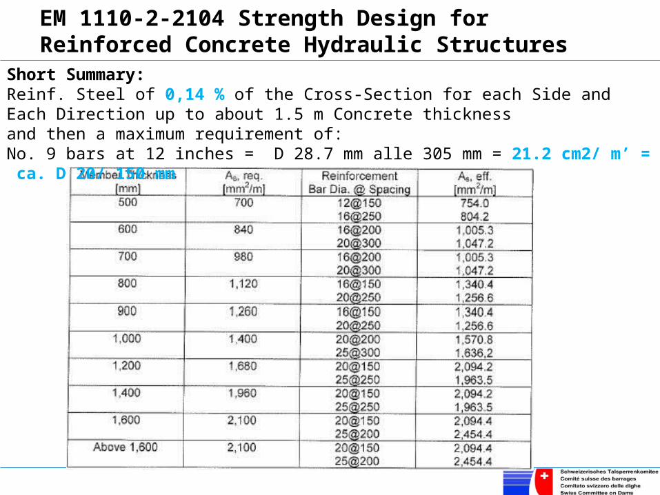
EM 1110-2-2104 Strength Design for Reinforced Concrete Hydraulic Structures
Short Summary: Reinf. Steel of 0,14 % of the Cross-Section for each Side and Each Direction up to about 1.5 m Concrete thicknessand then a maximum requirement of: No. 9 bars at 12 inches = D 28.7 mm alle 305 mm = 21.2 cm2/ m’ = ca. D 20/ 150 mm

The American Codes & GuidelinesACI207.2R-95 and ACI207.2R-07 Effect of Restraint, Volume Change, and Reinforcement on Cracking of Mass ConcreteThe ACI207.2R-95 approach is very similar to that of EM1110-2-2104 with the exception that 0.0015Ag is required instead of 0.0028Ag, and #6@12inch (D=19.1mm @304.8mm= 9.4 cm2/m’) instead of #9@12iches (21.2 cm2/m’). However, the above approach was withdrawn in September 2007 with the release of a new ACI207.2R-07 which refers to ACI224R-01 (Reapproved 2008) “Control of Cracking in Concrete Structures.” It is pertinent to note that ACI224R-01 does not limit reinforcement.Instead ACI224R-01 gives the following measures to limit cracking:• Concrete with large tensile-strain capacity;• Low cement content (permitted by low design stresses);• Cement of low heat generation (such as with the) use of pozzolans;• Cast small concrete segments or blocks;• Low placement temperature;• Slow rate of construction when no artificial cooling is used;• Artificial cooling by an internal network of cold water pipes;• Insulate concrete surfaces;• Low degree of restraint, as with yielding foundation, or in portions of the structure well removed from restraining foundation; and• Absence of stress raisers, such as galleries.

The American Codes & GuidelinesACI223-98 & ACI223R-10 Standard Practice for the Use of Shrinkage-Compensating ConcreteThe ACI223-98 approach is very similar to that of ACI207.2R-95 with a maximum of 0.0015Ag and the #6 (19.1mm) @12inch (304.8mm) limit. It also states:Not less than one-half, nor more than two-thirds of the total quantity of reinforcement should be placed in any one face. The maximum bar spacing should be limited to 12 in.ch (304.8mm) on centers. For members more than 48 inch (1.22m) thick the minimum temperature and shrinkage requirements in each face should be limited by depth of cover “dc” and bar spacing “s” such that: A= [2*dc * s] and
Considering dc=75mm and s=200mm this gives As’= 3cm2/mHowever, the above approach was withdrawn in December 2010 with the release of a new ACI223-10 which refers to ACI318 and ACI350.

The American Codes & GuidelinesACI 318M-11 Building Code Requirements for Structural ConcreteThese code requirements apply to normal buildings but some state agencies require them also for hydraulic structures such as powerhouses.ACI318 requirements for shrinkage and temperature steel are as follows:
Therefore: 0.18 % = 18 cm2/m’ for each meter of Concrete thickness with the usual material propertiesNote: ACI318 no longer uses exposure factor “Z” since 2002. (The Z-factor limited crack width indirectly to 0.41mm for interior and 0.33mm for exterior exposure).

The American Codes & GuidelinesACI 318M-11 Building Code Requirements for Structural ConcreteInstead of the Z-factor ACI318 §10.6.4 limits the spacing “s” of the reinforcement steel
Note: With Grade 420 reinforcement and 50 mm clear cover to the main reinforcement, with fs = 280 MPa, the maximum bar spacing is 250 mm.However, ACI 318M-08 §10.6.5 states that the above limit does not apply for concrete subjected to very severe exposure or for water-tight structures. For such structures, special investigations and precautions are required.
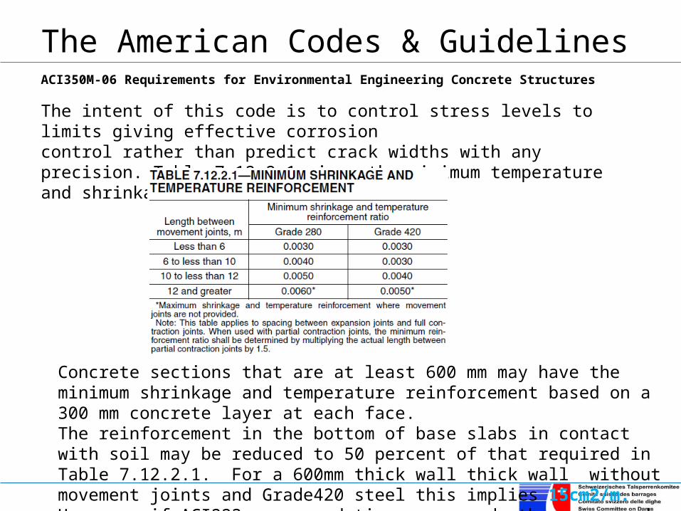
The American Codes & GuidelinesACI350M-06 Requirements for Environmental Engineering Concrete StructuresThe intent of this code is to control stress levels to limits giving effective corrosion control rather than predict crack widths with any precision. Table 7.12.2.1 gives the minimum temperature and shrinkage reinforcement:
Concrete sections that are at least 600 mm may have the minimum shrinkage and temperature reinforcement based on a 300 mm concrete layer at each face.The reinforcement in the bottom of base slabs in contact with soil may be reduced to 50 percent of that required in Table 7.12.2.1. For a 600mm thick wall thick wall without movement joints and Grade420 steel this implies 15cm2/m. However, if ACI223 recommendations are used, then one need not apply the table.

The American Codes & GuidelinesACI350M-06 Requirements for Environmental Engineering Concrete StructuresThe max. spacing is limited: “In walls and slabs primary flexural reinforcement it shall not be spaced farther apart than two times the wall or slab thickness, nor farther apart than 300 mm.” It also specifies crack control as a function of bar spacing and serviceability level reinforcing steel stress “fs”, and gives :
“fs” needs not be less than 115 MPa for one-way and 140 MPa for two-way members. Note it shall be permitted to use the value 16,000 for the term 4(50 + db /2)2 as a simplification. As per §10.6.4.4 , the strain gradient amplification factor is given by:
and severe exposure
for normal conditions
“fs” needs not be less than 140 MPa for one-way and 165 MPa for two-way members.

The American Codes & GuidelinesACI350M-06 Requirements for Environmental Engineering Concrete Structures
In graphical form the above translates into the following four figures from the Commentary §R10.6.4:
Note “c”, (the distance from extreme compression fiber to the neutral axis) is calculated at service loads. In lieu of this more precise calculation, it shall be permitted to use β equal to 1.2 for h ≥ 400 mm and 1.35 for h < 400mm.
According ACI350 environmental exposure conditions are defined by §10.6.4.5:Normal environmental exposure, for liquid retention, is defined as exposure to liquids with a pH greater than 5, or exposure to sulfate solutions of ≤1000 ppm. Severe environmental exposures are conditions in which the limits defining normal environmental exposure are exceeded.
It must be noted that abiding by these charts will not ensure complete liquid-tightness; for this one needs to refer to ACI 350.1-01, “Standard Practice for Tightness Testing of Environmental Engineering Concrete Structures.” It gives the rate of filling and guidelines for losses.

The American Codes & GuidelinesACI350M-06 Requirements for Environmental Engineering Concrete Structures

The British Codes & GuidelinesIn the United Kingdom code requirements of hydraulic structures were governed by BS 8007:1987 “Design of concrete structures for retaining aqueous liquids”In 2006 it was replaced by EN 1992-3:2006. Nevertheless, since it is still being used in many ex-colonies of England, or adaptation thereof in their national codes, a summary is given below:
Maximum design surface crack widths for direct tension and flexure orrestrained temperature & moisture effects are:•0.2 mm for severe or very severe exposure •0.1 mm for critical aesthetic cases
Two independent methods to calculate crack widths:
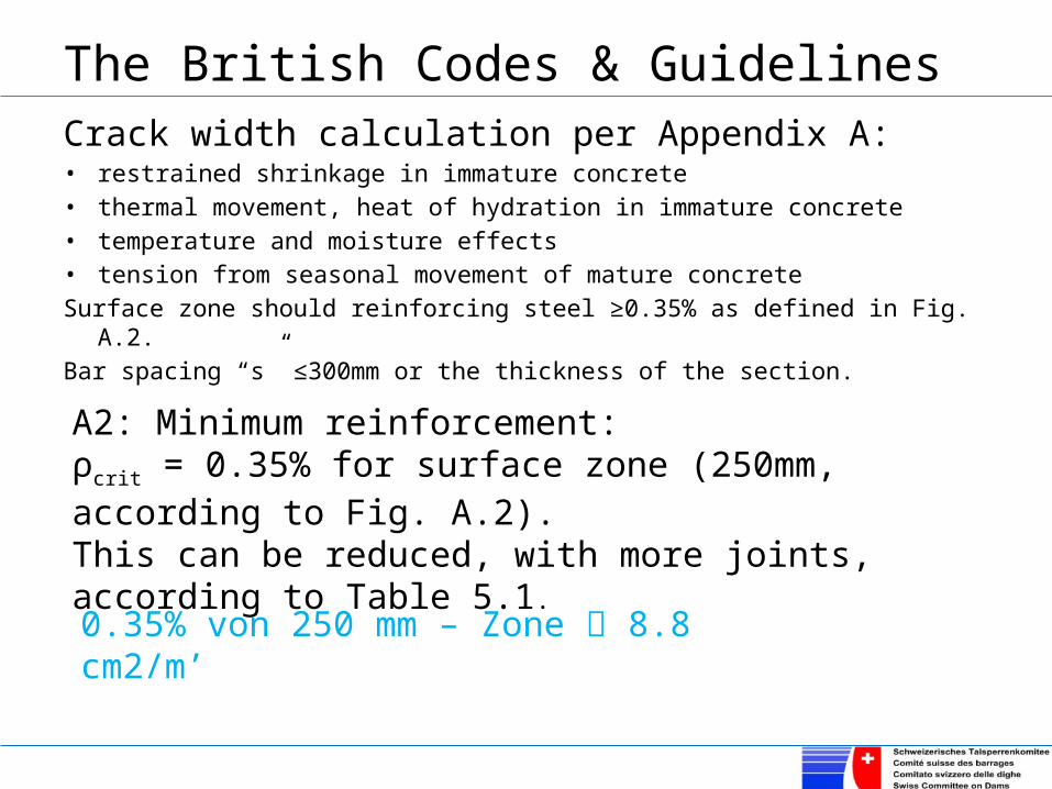
The British Codes & GuidelinesCrack width calculation per Appendix A: • restrained shrinkage in immature concrete• thermal movement, heat of hydration in immature concrete• temperature and moisture effects• tension from seasonal movement of mature concreteSurface zone should reinforcing steel ≥0.35% as defined in Fig. A.2.Bar spacing “s” ≤300mm or the thickness of the section.
A2: Minimum reinforcement:ρcrit = 0.35% for surface zone (250mm, according to Fig. A.2). This can be reduced, with more joints, according to Table 5.1.
0.35% von 250 mm – Zone 8.8 cm2/m’

The British Codes & Guidelines
A3: Crack Spacing: First, the likely maximum spacing of cracks is calculated
2*67.0max s
The width wmax of the crack is calculated:
)21(***maxmax TTRsw

The British Codes & GuidelinesOnly thermal contraction is considered, shrinkage & creep effects cancel each other out. T1 is the fall in temperature between hydration peak and ambient, see Table A.2 (with higher placing temperatures, the hydration peak values increase maximal by 15%).

The British Codes & GuidelinesT2 is the further fall in temperature because of seasonal variations in mature concrete. If movement joints are provided as Option 2 or 3 of Table 5.1, T2 need not to be considered, provided steel has been reduced by 50% at partial contraction joint.

The British Codes & GuidelinesThe second method of crack width determination is deterministic and given in Appendix B.
acr = distance from the point considered to the surface of the nearest longitudinal bar
ε1 = strain at the selected level based on a cracked sectional analysis= εs(a – x)/(d – x); where distance from the compression face to the level at which crack width is calculated; a = h at the soffit i.e.: the tension surface.
For a limiting design surface crack width of 0.2 mm:
For a limiting design surface crack width of 0.1 mm:

The British Codes & GuidelinesThe procedure can be programed in EXCEL and can be downloaded from the British Concrete Council. Project
Spreadsheets to BS 8110etc Client Advisory Group Made by Date Page Location Grid line 1 RC 10-May-2014 33
Crack Width Calculations to BS8110: 1997/ BS8007:1987 Checked Revision J ob No Originated from RCC14.xls on CD © 1999 BCA for RCC chg R68
CRACK WIDTH CALCULATIONS - FLEXURE -
INPUTfcu= 35 N/mm2
fy= 460 N/mm2
Area of reinforcement " As " = 2093 mm2
b = 1000 mmh = 250 mmd = 200 mm
Minimum cover to tension reinforcement " CO " = 40 mmMaxmum bar spacing " S " = 150 mm
Bar dia " DIA " = 20 mm " acr " =(((S/2)̂ 2+(CO+DIA/2)̂ 2)̂ (1/2)-DIA/2) as default or enter other value = 80.1 mm
"acr " is distance from the point considered to the surface of the nearest longitudinal barApplied service moment " Ms "= 69.0 KNm
CALCULATIONSmoduli of elasticity of concrete " Ec" = (1/2)*(20+0.2*fcu) = 13.5 KN/mm2
moduli of elasticity of steel " Es " = 200.0 KN/mm2
Modular ratio " " = (Es/Ec) = 14.81 " " = As/bd = 0.010
depth to neutral axis, "x" = (-. +((.)2 + 2..)0.5.d = 85 mm
" Z " = d-(x/3) = 172Reinforcement stress " fs " = Ms/(As*Z) = 192 N/mm2
Concrete stress " fc " = (fs*As)/(0.5*b*x) = 9.50 N/mm2
Strain at soffit of concrete beam/slab " e1 " = (fs/Es)*(h-x)/(d-x) = 0.001375Strain due to stiffening effect of concrete between cracks " e2 " =
e2 = b.(h-x)2/(3.Es.As.(d-x)) for crack widths of 0.2 mm Usede2 = 1.5.b.(h-x)2/(3.Es.As.(d-x)) for crack widths of 0.1 mm n/a
e2 = 0.000189Average strain for calculation of crack width " em "= e1-e2 = 0.001186
Calculated crack width, " w " = 3.acr.em/(1+2.(acr-c)/(h-x))CALCULATED CRACK WIDTH, 'w' = 0.19 mm
REINFORCED CONCRETE COUNCIL
-

Conclusions
• The American approach is empirical
• The British Approach is deterministic
• The European Code is replacing the British Approach except in its previous colonies, which still use either the British Code or a National Code based on it.

THANK YOU FOR YOUR ATTENTION
VIELEN DANK FÜR IHRE AUFMERKSAMKEIT
Minimum Steel Requirements –Comparison of USA and British Code Requirements