minimally invasive approach for surgical treatment of
TRANSCRIPT

MINIMALLY INVASIVE APPROACH
FOR SURGICAL TREATMENT OF
PROXIMAL FEMUR FRACTURES
by
Jugal Parekh
A thesis submitted to the
University of Birmingham
for the degree of
DOCTOR OF PHILOSOPHY
Bio-medical and Micro Engineering Research Centre
School of Mechanical Engineering
College of Engineering and Physical Sciences
University of Birmingham
December 2011

University of Birmingham Research Archive
e-theses repository This unpublished thesis/dissertation is copyright of the author and/or third parties. The intellectual property rights of the author or third parties in respect of this work are as defined by The Copyright Designs and Patents Act 1988 or as modified by any successor legislation. Any use made of information contained in this thesis/dissertation must be in accordance with that legislation and must be properly acknowledged. Further distribution or reproduction in any format is prohibited without the permission of the copyright holder.
ABSTRACT
Minimally invasive surgery (MIS) is fast becoming a preferred choice for patients
and surgeons, due to its biological, aesthetic and commercial benefits. The
dynamic hip screw (DHS) is the standard implant for the treatment of fractures of
the proximal femur, which is considered to be the most frequent injury in the
elderly. The aim of this research was to develop MIS for the treatment of these
fractures utilising the principle and surgical technique of the DHS implant. During
the research, a thorough medical device design process was conducted to develop
three new medical devices – a new angle guide, a new ergonomic T-handle and a
new implant. The design process for each of the new medical devices conformed
to requirements of the relevant standards. The designs of the new medical devices
were verified using methods such as risk analysis, finite element analysis and
mechanical testing of manufactured prototype. Finally, an operative technique
applying a minimally invasive approach with the new medical devices was
developed to treat the fractures of the proximal femur.

ACKNOWLEDGEMENTS
I would like to take this opportunity to thank the following people.
David Hukins and Duncan Shepherd who believed I could do better than I
thought and made me work to my full capacity to complete this thesis. Your
invaluable teachings and constant supervision in person and by mails has brought
about this thesis which I can be proud of.
Prof. Nicola Maffulli for having the faith that I could execute your vision and for
giving me this opportunity to fulfil my dream of achieving a PhD. Your financial
and intellectual support has enabled this PhD.
Carl Hingley, Lee Gauntlett, Peter Thornton and Alan Saywell for their 24×7
flawless technical support and a special thank you for the manufacturing of
various testing rigs for my experiments.
Marilyn Hinton and Helen Booth for their promptness in administrative services
and for always being there!
My lab members, namely Farnaz, Purvi, Aziza, Pauliena, Parshia, Theo, and Lei
who constantly helped me through the highs and lows of the PhD, and for all the
running around when I most needed it!
Arjun, Anish, Joy, Shiv and Stergios for their unconditional friendship.
Mr Balkrishna and Mrs Bharati Popawala, without whom, this stage in my life
would be impossible. I’ll always be grateful for your love and blessings.
My parents and teachers for life, Mr Rajendra and Mrs Lata Parekh, for sacrificing
more than I can imagine for my progress. I hope that we have made you proud in
return for your undivided dedication towards your children.
Brinda and Devang for their love, advice, eternal care and gifting me with a
precious niece.
My loving wife, Jyothi, for her constant faith and support throughout the course of
this PhD. It has been your care, quirkiness and love that kept me grounded to
reality. I thank you for your patience and understanding over the years.
My heartfelt and sincere thanks to all my family members, friends, colleagues and
well-wishers.

TABLE OF CONTENTS
1. INTRODUCTION ......................................................................................................... 1
2. MEDICAL DEVICE DESIGN PROCESS ................................................................. 4
2.1 CHAPTER AT A GLANCE ............................................................................................... 4
2. 1. 1. Chapter overview................................................................................................ 4
2. 1. 2. Keywords ............................................................................................................ 4
2. 2. INTRODUCTION .......................................................................................................... 5
2. 3. DESIGN PROCESS ........................................................................................................ 5
2.3.1. Overview .............................................................................................................. 5
2.3.2. Feasibility ............................................................................................................. 7
2.3.3. Concept Evolution ................................................................................................ 8
2.3.4. Specification testing ........................................................................................... 11
2.3.5. Detail design ...................................................................................................... 12
2.3.6. Design presentation ........................................................................................... 15
2. 4. NOTE ON STANDARDS AND REQUIREMENTS ........................................................... 16
2. 5. SUMMARY ................................................................................................................. 17
3. FEASIBILITY OF NEW MEDICAL DEVICES FOR HIP FRACTURES ........... 18
3. 1 CHAPTER AT A GLANCE ............................................................................................ 18
3. 1. 1. Chapter overview.............................................................................................. 18
3. 1. 2. Keywords .......................................................................................................... 18
3. 2. INTRODUCTION ........................................................................................................ 19
3. 3. THE FEMUR .............................................................................................................. 20
3. 4. FRACTURES OF THE PROXIMAL FEMUR ................................................................... 23
3. 4. 1. Overview .......................................................................................................... 23
3. 4. 2. Anatomical Locations of the Fractures............................................................. 23
3. 4. 3. Cause of the fracture ......................................................................................... 25
3. 4. 4. Epidemiology of the fracture ............................................................................ 25
3. 4. 5. Morbidity and mortality due to the fracture .................................................... 28
3. 5. TREATMENT OF INTERTROCHANTERIC FRACTURES OF THE PROXIMAL FEMUR ..... 28
3. 5. 1. Overview .......................................................................................................... 28
3. 5. 2. Surgical treatment of hip fractures .................................................................. 29
3. 5. 3. Intra-Medullary or DHS? ............................................................................... 31
3. 6. DYNAMIC HIP SCREW (DHS) .................................................................................. 32
3. 6. 1. The implant ...................................................................................................... 32
3. 6. 2. Evolution of the DHS implant ......................................................................... 35

3. 6. 3. Surgical procedure for implanting a DHS implant ......................................... 36
3. 7. MINIMALLY INVASIVE SURGERIES (MIS) ............................................................... 43
3. 8. REVIEW OF EXISTING MIS TECHNIQUES FOR PROXIMAL FEMUR FRACTURES .......... 44
3. 8. 1. Overview .......................................................................................................... 44
3. 8. 2. Alternative Surgical Approach ........................................................................ 45
3. 8. 3. Similar Surgical Approach ............................................................................... 47
3.9. IDENTIFIED MEDICAL DEVICES FOR MIS OF DHS .................................................... 51
3. 9. 1. Overview .......................................................................................................... 51
3. 9. 2. Design Brief ..................................................................................................... 52
3. 9. 3. Product Design Specifications of the Identified Medical Devices ................... 53
3. 10. SUMMARY ............................................................................................................... 71
4. CONCEPT OF A NEW ANGLE GUIDE ................................................................. 72
4.1 CHAPTER AT A GLANCE ............................................................................................. 72
4. 1. 1. Chapter overview.............................................................................................. 72
4. 1. 2. Keywords .......................................................................................................... 72
4. 2. INTRODUCTION ........................................................................................................ 73
4. 3. EXISTING ANGLE GUIDES .......................................................................................... 74
4. 4. DESIGN OBJECTIVES OF A NEW ANGLE GUIDE .......................................................... 80
4. 5. DESIGN REQUIREMENTS OF A NEW ANGLE GUIDE ................................................... 80
4. 5. 1. Overview .......................................................................................................... 80
4. 5. 2. Function ........................................................................................................... 81
4. 5. 3. Forces................................................................................................................ 81
4. 5. 4. Material ............................................................................................................ 84
4. 5. 5. Shape and Dimensions ..................................................................................... 85
4. 5. 6. Ergonomics and design attributes .................................................................... 85
4. 5. 7. Base plate and surface of femur ........................................................................ 86
4. 5. 8. Single-use or re-use market .............................................................................. 87
4. 6. EVOLUTION OF A CONCEPT ...................................................................................... 89
4. 6. 1. Overview .......................................................................................................... 89
4. 6. 2. Idea 1 ................................................................................................................ 90
4. 6. 3. Idea 2 ................................................................................................................ 91
4. 6. 4. Idea 3a/ 3b ........................................................................................................ 94
4. 6. 5. Idea 4 ................................................................................................................ 95
4. 6. 6. Concept Evaluation .......................................................................................... 95
4. 6. 7. Concept of a new angle guide ........................................................................... 98
4. 7. SUMMARY ............................................................................................................... 100
5. A NEW BASE MATERIAL FOR THE NEW ANGLE GUIDE .......................... 101
5. 1. CHAPTER AT A GLANCE ......................................................................................... 101

5. 1. 1. Chapter overview............................................................................................ 101
5. 1. 2. Keywords ........................................................................................................ 101
5. 2. INTRODUCTION ...................................................................................................... 102
5. 3. INVESTIGATION OBJECTIVE .................................................................................... 103
5. 4. MATERIALS AND METHODS .................................................................................. 104
5. 4. 1. Variables affecting the measurement of coefficient of friction ........................ 104
5. 4. 2. Bone specimen ................................................................................................ 106
5. 4. 3. Stainless steel samples .................................................................................... 107
5. 4. 4. Silicone elastomer samples ............................................................................. 108
5. 4. 5. Blood analogue solution ................................................................................. 109
5. 4. 6. Measurement of coefficient of friction ............................................................ 110
5. 4. 7. Data analysis .................................................................................................. 114
5. 4. 8. Statistics analysis ........................................................................................... 115
5. 5. RESULTS .................................................................................................................. 119
5. 6. IMPLICATIONS OF RESULT ON MATERIAL SELECTION ............................................ 123
5. 7. SUMMARY ............................................................................................................... 126
6. THE NEW ANGLE GUIDE...................................................................................... 127
6.1 CHAPTER AT A GLANCE ........................................................................................... 127
6. 1. 1. Chapter overview............................................................................................ 127
6. 1. 2. Keywords ........................................................................................................ 127
6. 2. INTRODUCTION ...................................................................................................... 128
6. 3. THE NEW ANGLE GUIDE IN DETAIL ........................................................................ 128
6. 3. 1. Design Overview ........................................................................................... 128
6. 3. 2. New base ......................................................................................................... 133
6. 3. 3. Material .......................................................................................................... 134
6. 4. RISK ANALYSIS ....................................................................................................... 135
6. 5. FINITE ELEMENT ANALYSIS (FEA) ........................................................................ 137
6. 5. 1. Overview ........................................................................................................ 137
6. 5. 2. Pre-processing ................................................................................................ 138
6. 5. 3. Post-processing .............................................................................................. 140
6. 6. THE NEW ANGLE GUIDE ......................................................................................... 142
6. 7. SUMMARY ............................................................................................................... 143
7. THE NEW ERGONOMIC T-HANDLE ................................................................. 144
7.1 CHAPTER AT A GLANCE ........................................................................................... 144
7. 1. 1. Chapter Overview .......................................................................................... 144
7. 2. INTRODUCTION ...................................................................................................... 145
7. 3. DESIGN OBJECTIVES OF A NEW T-HANDLE ............................................................ 147
7. 4. EXISTING T-HANDLES ............................................................................................ 147

7. 5. DESIGN REQUIREMENTS FOR THE NEW DHS T-HANDLE ...................................... 150
7. 5. 1. Overview ....................................................................................................... 150
7. 5. 2. Function ......................................................................................................... 151
7. 5. 3. Grip ................................................................................................................ 151
7. 5. 4. Size ................................................................................................................. 152
7. 5. 5. Cross section................................................................................................... 154
7. 5. 6. Material .......................................................................................................... 155
7. 5. 7. Shape .............................................................................................................. 155
7. 6. EVOLUTION OF A NEW CONCEPT ........................................................................... 156
7. 6. 1. Concept 1 ........................................................................................................ 156
7. 6. 2. Concept 2 ........................................................................................................ 158
7. 7. THE NEW ERGONOMIC T-HANDLE IN DETAIL ....................................................... 159
7. 7. 1. Overview of the design ................................................................................... 159
7. 7. 2. Material of the new T-handle ........................................................................ 163
7. 8. DESIGN VERIFICATION ........................................................................................... 164
7. 9. THE NEW ERGONOMIC T-HANDLE ......................................................................... 166
7. 10. SUMMARY OF THE DESIGN PROCESS ..................................................................... 166
8. CONCEPT OF A NEW IMPLANT ......................................................................... 167
8.1 CHAPTER AT A GLANCE ........................................................................................... 167
8. 1. 1. Chapter overview............................................................................................ 167
8. 1. 2. Keywords ........................................................................................................ 167
8. 2. INTRODUCTION ...................................................................................................... 168
8. 3. DESIGN OBJECTIVES ................................................................................................ 170
8. 4. DESIGN SPECIFICATIONS ........................................................................................ 170
8. 4. 1. Overview ........................................................................................................ 170
8. 4. 2. Functional characteristics .............................................................................. 171
8. 4. 3. Fracture treatment ......................................................................................... 171
8. 4. 4. Sliding mechanism ......................................................................................... 172
8. 4. 5. Material .......................................................................................................... 173
8. 4. 6. Lag screw ........................................................................................................ 174
8. 4. 7. Side plate ........................................................................................................ 177
8. 4. 8. Surgical Technique ......................................................................................... 180
8. 4. 9. Dimensions .................................................................................................... 181
8. 4. 10. Mechanical testing ....................................................................................... 183
8. 5. EVOLUTION OF A CONCEPT .................................................................................... 183
8. 5. 1. Overview ........................................................................................................ 183
8. 5. 2. Concept 1 ........................................................................................................ 184
8. 5. 3. Concept 2 ........................................................................................................ 186
8. 6. SUMMARY ............................................................................................................... 189

9. THE NEW IMPLANT ............................................................................................... 190
9.1 CHAPTER AT A GLANCE ........................................................................................... 190
9. 1. 1. Chapter overview............................................................................................ 190
9. 1. 2. Keywords ........................................................................................................ 190
9. 2. INTRODUCTION ...................................................................................................... 191
9. 3. NEW IMPLANT IN DETAIL ....................................................................................... 192
9. 3. 1. Implant overview............................................................................................ 192
9. 3. 2. Angled side plate ............................................................................................ 194
9. 3. 3. Telescoping screw ........................................................................................... 197
9. 4. RISK ANALYSIS ....................................................................................................... 199
9. 5. FINITE ELEMENT ANALYSIS (FEA) ........................................................................ 202
9. 5. 1. Overview ........................................................................................................ 202
9. 5. 2. Pre-processing ................................................................................................ 203
9. 5. 3. Post-processing .............................................................................................. 208
9. 6 PROTOTYPE MANUFACTURE ................................................................................... 210
9. 6. 1. Overview ........................................................................................................ 210
9. 6. 2. FEA of prototype ............................................................................................ 214
9. 6. 3 The manufactured prototype ........................................................................... 214
9. 7. MECHANICAL TESTING .......................................................................................... 215
9. 7. 1. Investigation objective .................................................................................... 215
9. 7. 2. Materials and method .................................................................................... 216
9. 7. 3. Results ............................................................................................................ 221
9. 7. 4. Implications of results .................................................................................... 223
9. 8. THE NEW IMPLANT ................................................................................................. 224
9. 9. SUMMARY ............................................................................................................... 225
10. OPERATIVE TECHNIQUE FOR THE NEW IMPLANT ................................. 226
10.1 CHAPTER AT A GLANCE ......................................................................................... 226
10. 1. 1. Chapter overview.......................................................................................... 226
10. 1. 2. Keywords ...................................................................................................... 226
10. 2. INTRODUCTION .................................................................................................... 227
10. 3. THE NEW IMPLANT ............................................................................................... 228
10. 3. 1. Overview ...................................................................................................... 228
10. 3. 2. Angled side plate .......................................................................................... 228
10. 3. 3. Telescoping screw ......................................................................................... 230
10. 3. 4. Potential features and benefits ..................................................................... 231
10. 4. INSTRUMENTS FOR A MINIMALLY INVASIVE SURGERY ........................................ 232
10. 4. 1. Overview ...................................................................................................... 232
10. 4. 2. An ergonomic T-handle................................................................................ 232
10. 4. 3. New angle guide ........................................................................................... 234

10. 4. 4. Side plate inserter ......................................................................................... 235
10. 4. 5. Telescoping screw inserter ........................................................................... 236
10. 4. 6. Other instruments ....................................................................................... 237
10. 5. OPERATIVE TECHNIQUE ....................................................................................... 238
10. 5. 1. Overview ...................................................................................................... 238
10. 5. 2. Guide pin placement (Green) ....................................................................... 238
10. 5. 3. Reaming and tapping (Yellow) .................................................................... 240
10. 5. 4. Side plate fixation (Orange) ......................................................................... 241
10. 5. 5. Telescoping screw insertion (Blue) .............................................................. 243
10. 5. 6. Completion ................................................................................................... 244
10. 6. SUMMARY ............................................................................................................. 245
11. CONCLUSIONS ...................................................................................................... 246
APPENDIX A. SURGEON’S PERSPECTIVE ON A NEW BASE MATERIAL . 252
A. 1. INTRODUCTION ..................................................................................................... 252
A. 2. MATERIALS AND METHODS ................................................................................. 253
A. 2. 1. Instruments ................................................................................................... 253
A. 2. 2. Setup of Apparatus ........................................................................................ 254
A. 2. 3. Questionnaire and respondents .................................................................... 254
A. 2. 4. Evaluating the surgeon’s perspective ............................................................ 255
A. 3. RESULTS................................................................................................................. 256
A. 3. 1. The handle ..................................................................................................... 256
A. 3. 2. The base material ........................................................................................... 257
A. 3. 3. General questions .......................................................................................... 257
A. 4. DISCUSSION ........................................................................................................... 259
A. 5. CONCLUSIONS ....................................................................................................... 260
A. 6. QUESTIONNAIRE ................................................................................................... 261
APPENDIX B. THE NEW IMPLANT – MODEL 1 .................................................. 266
B.1. INTRODUCTION ...................................................................................................... 266
APPENDIX C. NEW INSTRUMENTS FOR THE NEW IMPLANT .................... 271
C.1. INTRODUCTION ...................................................................................................... 271
LIST OF REFERENCES ................................................................................................ 274

LIST OF FIGURES
FIGURE 2.1: FLOWCHART OF THE CHAPTER STRUCTURE ................................. 4
FIGURE 2.2: TOTAL DESIGN APPROACH PROPOSED BY PUGH IN 1985 .......... 6
FIGURE 2.3: DESIGN APPROACH UTILISED FOR THE RESEARCH
PRESENTED IN THIS THESIS ......................................................................................... 7
FIGURE 3.1: FLOWCHART OF THE CHAPTER STRUCTURE ............................... 18
FIGURE 3.2: LOCATION OF FEMUR RELATIVE TO THE BONES OF THE
LOWER EXTREMITY....................................................................................................... 20
FIGURE 3.3: ANATOMY OF THE FEMUR. ................................................................. 21
FIGURE 3.4: ANATOMICAL REGIONS OF THE PROXIMAL FEMUR. ................ 24
FIGURE 3.5: EPIDEMIOLOGY OF HIP FRACTURES ................................................ 27
FIGURE 3.6: TARGON® PF INTRA-MEDULLARY NAIL ........................................ 30
FIGURE 3.7: EXPLODED VIEW OF A GENERIC DYNAMIC HIP SCREW ........... 33
FIGURE 3.8: TIMELINE OF EVOLUTION OF DHS ................................................... 35
FIGURE 3.9: GENERIC DHS ANGLE GUIDE ............................................................. 37
FIGURE 3.10: GUIDE PINS (DIAMETER – 3MM) ...................................................... 37
FIGURE 3.11: GENERIC MEASURING GAUGE......................................................... 38
FIGURE 3.12: GENERIC TRIPLE REAMER TO MAKE TUNNEL OF THREE
DIFFERENT DIAMETERS .............................................................................................. 38
FIGURE 3.13: GENERIC TAP ......................................................................................... 39
FIGURE 3.14: GENERIC INSERTION WRENCH ....................................................... 39
FIGURE 3.15: GENERIC T-HANDLE FOR USE WITH DIFFERENT
INSTRUMENTS IN THE DHS SURGERY .................................................................... 40
FIGURE 3.16: ILLUSTRATED SUMMARY OF SURGICAL STEPS 2 TO 4 TO
IMPLANT A DHS AND ANGLED PLATE. ................................................................. 40
FIGURE 3.17: INSERTION POINT OF GUIDE PIN IN CONTEXT TO VASTUS
LATERALIS ....................................................................................................................... 42
FIGURE 3.18: GOTFRIED PC.C.P (ORTHOFIX SRL, ITALY).. ................................. 46

FIGURE 3.19: TARGON® FN (B. BRAUN MELSUNGEN AG, MELSUNGEN,
GERMANY) FOR PROXIMAL FEMUR FRACTURES. .............................................. 47
FIGURE 4.1: FLOWCHART OF THE CHAPTER STRUCTURE ............................... 72
FIGURE 4.2: ANGLE GUIDE GRIPPING THE CURVED LATERAL SURFACE OF
A LEFT COMPOSITE BONE FEMUR ........................................................................... 76
FIGURE 4.3: ENGINEERING DRAWING OF THE 135 ANGLE GUIDE ................ 78
FIGURE 4.4: FORCES ACTING ON A GENERIC ANGLE GUIDE WHILST IN
USE...................................................................................................................................... 82
FIGURE 4.5: ANTERIOR AND LATERAL SCHEMATIC VIEW OF THE THIGH
REGION. ............................................................................................................................ 84
FIGURE 4.6: THREE DIMENSIONAL MODEL OF COMPOSITE BONE FEMUR 87
FIGURE 4.7: IDEA 1 FOR A NEW ANGLE GUIDE .................................................... 90
FIGURE 4.8: IDEA 2 FOR A NEW ANGLE GUIDE .................................................... 91
FIGURE 4.9: INNOVATIONS APPLIED TO THE BASE OF THE NEW ANGLE
GUIDE ................................................................................................................................ 93
FIGURE 4.10: A) IDEA 3A, AND B) IDEA 3B FOR A NEW ANGLE GUIDE ......... 94
FIGURE 4.11: IDEA 4 FOR A NEW ANGLE GUIDE .................................................. 96
FIGURE 4.12: A) FINAL CONCEPT OF THE NEW ANGLE GUIDE SHOWN
WITH A GUIDE PIN PASSING THROUGH IT, AND B) A MANUFACTURED
PROTOTYPE OF THE FINAL CONCEPT .................................................................... 99
FIGURE 5.1: FLOWCHART OF THE CHAPTER STRUCTURE ............................. 101
FIGURE 5.2: BONE SPECIMEN SECURED IN AN OPEN STEEL BOX WITH
ACRYLIC CEMENT ....................................................................................................... 107
FIGURE 5.3: SURFACE FINISHES PROVIDING ROUGHENED TEXTURE ON
STAINLESS STEEL SAMPLES ..................................................................................... 108
FIGURE 5.4: TEST RIG SETUP ON ELF 3200 TESTING MACHINE TO MEASURE
THE STATIC COEFFICIENT OF FRICTION ............................................................. 112
FIGURE 5.5: EXPLODED VIEW OF BONE-MATERIAL ASSEMBLY SETUP ON
THE TESTING RIG ......................................................................................................... 113
FIGURE 5.6: ENGINEERING DRAWING OF THE CUSTOM MADE TEST RIG
BASE USED TO MEASURE THE STATIC COEFFICIENT OF FRICTION ........... 116

FIGURE 5.7: ENGINEERING DRAWING OF THE HEIGHT-ADJUSTABLE
SPECIMEN BENCH, WHICH WAS SCREWED ON TO THE TESTING RIG ...... 117
FIGURE 5.8: ENGINEERING DRAWING OF THE NYLON PULLEY .................. 118
FIGURE 5.9: HORIZONTAL DISPLACEMENT OF BONE ON SILASTIC Q7-4780
WAS PLOTTED AGAINST FORCE REQUIRED TO INITIATE AND SUSTAIN
SLIDE ................................................................................................................................ 120
FIGURE 5.10: HORIZONTAL DISPLACEMENT OF BONE ON SPARK ERODED
STAINLESS STEEL WAS PLOTTED AGAINST FORCE REQUIRED TO INITIATE
AND SUSTAIN SLIDE ................................................................................................... 120
FIGURE 5.11: BREAKAWAY FORCE FOR BONE TO INITIATE SLIDE ON
SILASTIC Q7 – 4780 ....................................................................................................... 121
FIGURE 5.12: BREAKAWAY FORCE FOR BONE TO INITIATE SLIDE ON
SPARK ERODED STAINLESS STEEL SURFACE ..................................................... 122
FIGURE 6.1: FLOWCHART OF THE CHAPTER STRUCTURE ............................. 127
FIGURE 6.2A-B: THE NEW ANGLE GUIDE – A) VIEW OF THE BASE PLATE,
AND B) VIEW FROM THE SIDE PLANE .................................................................. 129
FIGURE 6.3: ENGINEERING DRAWING OF THE 120 TO 130 DEGREES NEW
ANGLE GUIDES ............................................................................................................. 131
FIGURE 6.4: ENGINEERING DRAWING OF THE 135 TO 150 DEGREES NEW
ANGLE GUIDES ............................................................................................................. 132
FIGURE 6.5: FEATURES OF THE NEW BASE ON THE 135 DEGREES NEW
ANGLE GUIDE ............................................................................................................... 133
FIGURE 6.6: THREE DIMENSIONAL MODEL OF THE 135 DEGREES NEW
ANGLE GUIDE ............................................................................................................... 138
FIGURE 6.7: CONVERGENCE PLOT TO SELECT MESH SIZE FOR 135 DEGREES
NEW ANGLE GUIDE. ................................................................................................... 139
FIGURE 6.8: MESHED MODEL OF THE NEW ANGLE GUIDE USING MESH
SIZE OF 1.50 MM ............................................................................................................ 140
FIGURE 6.9: GRAPHICAL REPRESENTATION OF FEA RESULTS ON THE 135
DEGREES NEW ANGLE GUIDE ................................................................................. 141
FIGURE 7.1: FLOW CHART OF THE CHAPTER STRUCTURE ............................ 144
FIGURE 7.2: ENGINEERING DRAWING OF THE GENERIC T-HANDLE ......... 149
FIGURE 7.3: DIFFERENT GRIPS OF THE HAND .................................................... 152

FIGURE 7.4: SKETCH OF A HAND DEPICTING THE ANTHROPOMETRIC
DATA TABULATED IN TABLE 7.1 ............................................................................ 153
FIGURE 7.5: CONCEPT 1 OF A NEW ERGONOMIC T-HANDLE ....................... 157
FIGURE 7.6: CONCEPT 2 OF A NEW ERGONOMIC T-HANDLE ....................... 159
FIGURE 7.7: A THREE-DIMENSIONAL RENDERED IMAGE OF A NEW
ERGONOMIC T-HANDLE FOR USE WITH INSTRUMENTS DURING MIS OF
DHS ................................................................................................................................... 161
FIGURE 7.8: ENGINEERING DRAWING OF THE NEW ERGONOMIC T-
HANDLE ......................................................................................................................... 162
FIGURE 7.9: THE THREE LAYERS OF MATERIALS TO BE USED IN THE NEW
T-HANDLE ...................................................................................................................... 164
FIGURE 8.1: FLOWCHART OF THE CHAPTER STRUCTURE ............................. 167
FIGURE 8.2: GENERIC DYNAMIC HIP SCREW (DHS) .......................................... 168
FIGURE 8.3: REGIONS OF A DHS LAG SCREW ...................................................... 175
FIGURE 8.4: REQUIREMENT OF INSERTING THE SIDE PLATE VERTICALLY
STRAIGHT TO SLIDE OVER THE PRE-INSERTED LAG SCREW ........................ 176
FIGURE 8.5: A GENERIC DHS ANGLED SIDE PLATE .......................................... 177
FIGURE 8.6: NOMENCLATURE OF DIMENSIONS OF A GENERIC 135
DEGREES DHS IMPLANT............................................................................................ 182
FIGURE 8.7: CONCEPT 1 OF THE NEW IMPLANT ................................................ 185
FIGURE 8.8: (A) TELESCOPING SCREW BEING ADVANCED THROUGH A
SECURED ANGLED SIDE PLATE; (B) AN ASSEMBLED CONCEPT 2 OF THE
NEW IMPLANT.............................................................................................................. 188
FIGURE 9.1: FLOWCHART OF THE CHAPTER STRUCTURE ............................. 190
FIGURE 9.2: NOMENCLATURE OF DIMENSIONS OF THE NEW IMPLANT IN
ACCORDANCE TO STANDARD BS 3531-15 (1992) ................................................ 194
FIGURE 9.3: ENGINEERING DRAWING OF THE ANGLED SIDE PLATE OF
THE NEW IMPLANT .................................................................................................... 196
FIGURE 9.4: REGIONS OF THE TELESCOPING SCREW OF THE NEW
IMPLANT ........................................................................................................................ 197
FIGURE 9.5: ENGINEERING DRAWING OF THE TELESCOPING SCREW OF
THE NEW IMPLANT .................................................................................................... 198

FIGURE 9.6: ENGINEERING DRAWING OF THE ANGLED SIDE PLATE OF
THE GENERIC DHS IMPLANT .................................................................................. 204
FIGURE 9.7: ENGINEERING DRAWING OF THE LAG SCREW OF THE
GENERIC DHS IMPLANT ............................................................................................ 205
FIGURE 9.8: THREE DIMENSIONAL MODELS OF A) THE NEW IMPLANT,
AND B) THE GENERIC DHS IMPLANT ................................................................... 206
FIGURE 9.9: CONVERGENCE PLOTS ....................................................................... 207
FIGURE 9.10: GRAPHICAL REPRESENTATION OF VON MISES STRESS
GENERATED ON A) THE NEW IMPLANT, AND B) THE GENERIC DHS
IMPLANT, DUE TO A LOAD OF 800 N DURING THE FEA ................................. 209
FIGURE 9.11: CHANGES MADE IN THE DESIGN OF THE NEW IMPLANT TO
EASE THE MANUFACTURING PROCESS ............................................................... 211
FIGURE 9.12: ENGINEERING DRAWING OF THE MODIFIED ANGLED SIDE
PLATE OF THE NEW IMPLANT FOR MANUFACTURE ...................................... 212
FIGURE 9.13: ENGINEERING DRAWING OF THE MODIFIED TELESCOPING
SCREW OF THE NEW IMPLANT FOR MANUFACTURE ..................................... 213
FIGURE 9.14: CUSTOM BUILT TEST RIG CONFIGURED FOR THE LOADING
TESTS ON THE BOSE ELF 3300 TESTING MACHINE ........................................... 217
FIGURE 9.15: ENGINEERING OF THE TEST RIG USED FOR THE
MECHANICAL TESTS DISCUSSED IN THIS SECTION ........................................ 220
FIGURE 9.16: GRAPH OF APPLIED LOAD, IN N, VERSUS DISPLACEMENT, IN
MM, REALISED IN THE NEW IMPLANT DURING THE STATIC LOADING
TEST .................................................................................................................................. 222
FIGURE 9.17: LOCATION OF FRACTURE ON THE PROTOTYPE ...................... 223
FIGURE 10.1: FLOWCHART OF THE CHAPTER STRUCTURE ........................... 226
FIGURE 10.2: THE NEW ANGLED SIDE PLATE ..................................................... 229
FIGURE 10.3: TELESCOPING SCREW ....................................................................... 230
FIGURE 10.4: COLOUR CODED ERGONOMIC T-HANDLES .............................. 233
FIGURE 10.5: THE NEW ANGLE GUIDE .................................................................. 234
FIGURE 10.6: SIDE PLATE INSERTER ....................................................................... 235
FIGURE 10.7: TELESCOPING SCREW INSERTER ................................................... 236

FIGURE 10.8: THE OTHER INSTRUMENTS TO BE USED DURING THE
SURGICAL PROCEDURE. ............................................................................................ 237
FIGURE 10.9: STEPS FOR GUIDE PIN PLACEMENT ............................................. 239
FIGURE 10.10: REAMING OF THE FEMUR USING A TRIPLE REAMER OVER
THE GUIDE PIN. ............................................................................................................ 241
FIGURE 10.11: STEPS FOR SIDE PLATE FIXATION ............................................... 242
FIGURE 10.12: STEPS FOR TELESCOPING SCREW INSERTION......................... 243
FIGURE 10.13: THE NEW IMPLANT ASSEMBLED AND SECURED ON TO THE
FEMUR. ............................................................................................................................ 244
FIGURE A.1: SETUP USED TO ASSESS THE SURGEON’S PERSPECTIVE OF AN
INSTRUMENT’S HANDLE AND THE BASE MATERIAL ..................................... 256
FIGURE B.1: MODEL 1 OF THE NEW IMPLANT .................................................... 267
FIGURE B.2: ENGINEERING DRAWING OF THE ANGLED SIDE PLATE OF
MODEL 1 OF THE NEW IMPLANT ........................................................................... 268
FIGURE B.3: ENGINEERING DRAWING OF THE TELESCOPING SCREW OF
MODEL 1 OF THE NEW IMPLANT ........................................................................... 269
FIGURE B.4: MODIFIED MANUFACTURED PROTOTYPE OF MODEL 1 ......... 270
FIGURE C.1: ENGINEERING DRAWING OF THE SIDE PLATE INSERTER ..... 272
FIGURE C.2: ENGINEERING DRAWING OF THE TELESCOPING SCREW
INSERTER ........................................................................................................................ 273

LIST OF TABLES
TABLE 2.1: RATINGS AS INDICATED BY OCCURRENCE, SEVERITY AND
DETECTION ...................................................................................................................... 13
TABLE 3.1: COMPARISON OF IMPLANTS ................................................................ 49
TABLE 4.1: SUMMARY OF THE EXISTING GENERIC ANGLE GUIDES ............. 79
TABLE 5.1: MEAN SURFACE ROUGHNESS (MM) MEASURED USING A
CONTACT METHOD ALONG WITH THEIR STANDARD DEVIATIONS ........ 119
TABLE 5.2: VALUES OF COEFFICIENT OF STATIC FRICTION, µ, FOR
DIFFERENT INTERFACES ........................................................................................... 123
TABLE 6.1: RISK ANALYSIS OF THE NEW ANGLE GUIDE ................................ 136
TABLE 7.1: ANTHROPOMETRIC MEASUREMENTS OF HAND FOR DESIGN
OF HAND TOOL HANDLES. ...................................................................................... 154
TABLE 7.2: RISK ANALYSIS CONDUCTED WITH THE FMEA METHOD ON
THE NEW T-HANDLE .................................................................................................. 165
TABLE 8.1: DIMENSIONS OF A GENERIC 135 DEGREES DHS IMPLANT
SHOWN IN FIGURE 8.6 ................................................................................................ 182
TABLE 9.1: DIMENSIONS OF THE NEW IMPLANT SHOWN IN FIGURE 9.2 .. 193
TABLE 9.2: RISK ANALYSIS OF THE NEW IMPLANT .......................................... 200
TABLE A.1. HANDLE DESIGN RATINGS SUMMARY .......................................... 258
TABLE A.2. BASE MATERIALS RATINGS SUMMARY ......................................... 259

Chapter 1 Introduction
1
Studies have established that hip fractures, also known as fractures of the
proximal femur, are considered to be frequent injuries in the elderly (Canale,
2002), and carry a lifetime risk of 15 to 17% amongst women and 5 to 6% in men
(Wong et al., 2009; Jewell et al., 2007; Van Staa et al., 2001). Surgery using a
dynamic hip screw (DHS) implant is the standard treatment option for the
treatment of such fractures (Chirodian et al., 2005; Harrington et al., 2002; Esser et
al., 1986).
Minimally invasive surgery (MIS) has proved to be beneficial for a variety of
reasons including reduced peri-operative blood loss and aesthetic appeal to the
patient due to less scarring (Ho et al., 2008; Peyser et al., 2005). Although it is
currently possible to administer MIS for treatment of such fractures, several
problems exist in implementing the approach including a steep learning curve for
the surgeons (Scuderi and Tria, 2010) and an increase of hospital inventory due to
additional instrumentation.
INTRODUCTION
Chapter 1 Introduction
2
The purpose of this research, initiated by Professor Nicola Maffulli (Professor of
Trauma and Orthopaedic Surgery, and Consultant orthopaedic surgeon, The
London Independent Hospital, London, UK), was to develop a minimally invasive
approach for the treatment of proximal femur fractures. The specific objectives of
this research, realised after the feasibility study, were to develop medical devices
capable of conducting the MIS procedure with an incision length of not more than
30 mm, and to utilise an operative technique that would be similar to the
conventional method used to implant the DHS.
Chapter 2 begins with a description of the stages of a design process of any
product. The chapter goes on to present the methodology of the design approach
used in this thesis for the development of the new medical devices. This thesis is
structured according to the core stages of the design process used in this research.
Chapter 3 presents a feasibility study to identify the specific medical devices that
would be redesigned during the course of this research. The study identifies three
medical devices, namely the angle guide, the T-handle and the DHS implant,
which would aid in establishing a MIS for the proximal femur fractures. This
chapter also serves as a background chapter for all three design processes in this
thesis.

Chapter 1 Introduction
3
Chapter 4 marks the beginning of the actual design of the medical devices.
Following that, the structure of the thesis is divided into four parts – Chapters 4 to
6 are for the design process of a new angle guide, Chapter 7 describes the
development of a new ergonomic T-handle, the new implant design is presented
in Chapters 8 and 9, and finally all the new devices are brought together for
exhibition in the operative technique for the new implant in Chapter 10, followed
by conclusions in Chapter 11.
This research involved three experiments, and they are described in detail in
Chapter 5, Chapter 9 and in Appendix A. The results of a test presented in
Chapter 5 were useful in selecting the new base material for the new angle guide.
The experiment in Chapter 9 follows the guidelines laid out in ASTM F-384 (2006)
to assess the strength of the new implant. Appendix A presents a survey
conducted at the City General Hospital (Stoke-on-Trent, UK) to assess the
surgeon’s perspective on the T-handle and the base material of a bone interfacing
instrument such as the angle guide. However, due to inconclusive results, the
findings were not incorporated into the design process of the new angle guide.
Appendix B provides engineering drawings of model 1 of the new implant, and
Appendix C presents the engineering drawings of two additional instruments that
were used in the surgical technique for the new implant in Chapter 10.

Chapter 2 Medical device design process
4
MEDICAL DEVICE DESIGN
PROCESS
2.1 Chapter at a glance
2. 1. 1. Chapter overview Figure 2.1 shows the chapter overview in the form of a flowchart.
Figure 2.1: Flowchart of the chapter structure
2. 1. 2. Keywords Concept design; design verification; medical device design; product design
specification; total design approach
Feasibility
Concept Evolution
Design Presentation
Detail design
Note on standards and
requirements
Medical device design
process
Chapter 2 Medical device design process
5
2. 2. Introduction
The stages of a medical device design process have to conform to certain
requirements as directed by the regulating standard (such as the Medical Device
Directive for Europe; Food and Drug Administration (FDA) for USA) to ensure the
safety of patients and healthcare staff. The purpose of this chapter is to explain in
detail the methodology of the design approach used during the development of
three medical devices in this research. The references used to compile the general
information in this chapter were Aitchison et al. (2009), Childs (2004), O’Leary
(2004), Wallace and Clarkson (1999), and Hill (1998).
2. 3. Design process
2.3.1. Overview
The core activities of the ‘total design’ approach to a generic design process as
proposed by Pugh in 1985 are shown in Figure 2.2. The steps of this approach
include market assessment, design specifications, conceptual design, detail design,
manufacturing and finally sales. It is important to review and revert back to
previous stages of the design process to achieve a superior design.

Chapter 2 Medical device design process
6
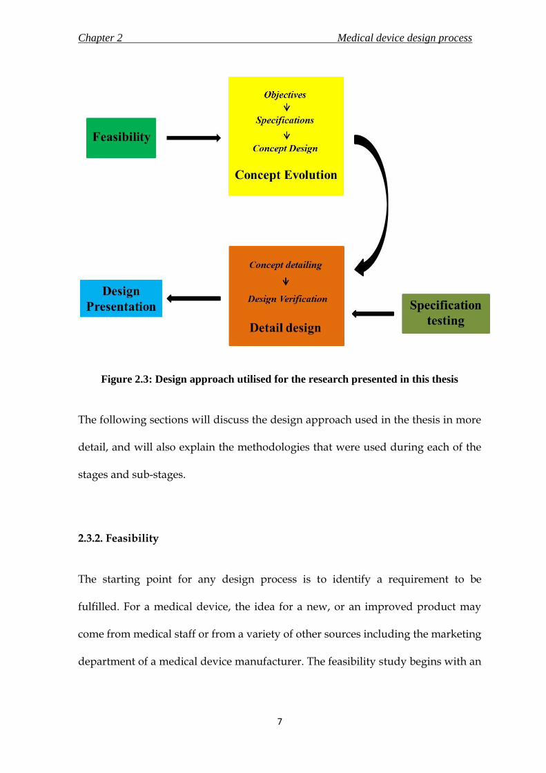
Figure 2.2: Total design approach proposed by Pugh in 1985
The purpose of this research was to design new medical devices, and hence the
total design approach was modified to implement the structure of this thesis. This
research covered design processes of three new medical devices to be used in the
same surgery. The design approach used during the development of the medical
devices is illustrated schematically in Figure 2.3. The core stages of the design
approach used in the thesis were feasibility, concept evolution, detail design and
design presentation. Furthermore, “specification testing” stage was added to the
above to include experiments conducted for evaluation of certain specifications
used in the detail design. In effect, the stages of design specifications and
conceptual design from the ‘total design’ approach were combined to form
concept evolution; manufacturing and sales from ‘total design’ approach was
replaced with design presentation for the context of this thesis. As seen in Figure
2.3, the different stages of the design approach are distinguished by unique
colours. Each chapter in this thesis is marked by one of the five representative
colours, which facilitates identification of the design stage discussed by the
respective chapter.
Chapter 2 Medical device design process
7
Figure 2.3: Design approach utilised for the research presented in this thesis
The following sections will discuss the design approach used in the thesis in more
detail, and will also explain the methodologies that were used during each of the
stages and sub-stages.
2.3.2. Feasibility
The starting point for any design process is to identify a requirement to be
fulfilled. For a medical device, the idea for a new, or an improved product may
come from medical staff or from a variety of other sources including the marketing
department of a medical device manufacturer. The feasibility study begins with an

Chapter 2 Medical device design process
8
assessment of the market for that particular medical device. It is important to
establish that the product is commercially viable and to research the market for
competition. The feasibility study should also identify the main aspects of the
idea, and determine the actual requirements of the product by the market. The
study yields the identification of medical devices and their general objectives to
achieve a solution for the requirement to be fulfilled.
The feasibility study for the new medical devices is discussed in Chapter 3 of this
thesis.
2.3.3. Concept Evolution
2.3.3.1. Overview
The feasibility stage identifies the market need and general requirements of a
medical device. The next step is to transform the general requirements into terse
objectives and specifications (often termed as the product design specification) of
the new medical device. Several concepts, which are able to combine the set
specifications, are generated through brain-storming. The concept which is most
effective in achieving the requirements is selected and taken up for further detail
design, either through scoring methods or by a panel of experts through feasibility
discussions based on factors such as performance and cost. The details of the sub-
Chapter 2 Medical device design process
9
stages of stating the specifications and selecting a concept are discussed in the
following sections.
Although the step of stating the product design specifications is generally a part of
the feasibility study (Aitchison et al., 2009), it was more appropriate for the
structure of this thesis to include it in the concept stage, as this research dealt with
three medical devices and their respective regulations, but with the same general
feasibility study. Specific feasibility studies were carried out, when required, to
gather more information for the design process (for example, the new T-handle in
Chapter 7) during the research.
2.3.3.2. Design Objectives
This step of the process is used to outline specific objectives that are expected of
the new medical device. The objectives are used as general guidelines, which are
to be adhered by all the specifications of the new concept. For example, the
objectives of the new implant designed in Chapters 8 to 10 were to allow for
incision of less than 30 mm, retain the principle mechanism of the dynamic hip
screw (DHS) implant and retrieve the experience of surgeons by designing a
similar surgical procedure as the DHS.

Chapter 2 Medical device design process
10
2.3.3.3. Design specifications
It is an extremely important task to prepare an elaborate and quantified (wherever
possible) product design specification (PDS) statement. The PDS captures a
framework of the exact requirements, through research and consultation, of the
medical device to be designed. The PDS is often referred to throughout the
remainder of the process to verify the design.
There are specific standards that were utilised as guides for laying out the
specifications for the medical devices designed in this research. The standard BS
EN 12011 (1998) has been produced to help identify the requirements for surgical
devices which include the intended performance, design attributes and materials
amongst other important headings. BS EN ISO 14630 (2009) was used to identify
the general requirements of the new implant designed in this research.
Furthermore, BS EN ISO 14602 (2010) and BS 3531-15 (1992) state the particular
requirements for implants to be used for osteosynthesis and for devices used for
fixation of ends of adult femurs. These and additional standards, that will be
discussed in later chapters, were used in developing PDS for the new medical
devices designed in this research.
Chapter 2 Medical device design process
11
2.3.3.4. Concept design
The first step in this stage involves generation of all the possible solutions that
concur with the design specifications laid out. It may be possible that some
concepts do not meet all the design requirements. However, these concept designs
are not to be discouraged at this point and effective brain-storming could be used
to search for the best idea. The concepts are reviewed against the requirements
laid out in the PDS to select the final concept either through a scoring method or
through discussion on the designs’ strengths and weaknesses.
During the design process of the medical devices in this research, some of the
generated concepts were considered stepping stones rather than feasible ideas and
were excluded from the write-up to maintain the flow and limit the length of this
thesis. The concepts were then evaluated subjectively by engineers and a
consultant surgeon, Professor N. Maffulli, and chosen on the basis of their
suitability and conformity to the PDS and the design objectives.
2.3.4. Specification testing
Although most specifications for the detailing were obtained through research of
publications and existing medical devices, it was also necessary to verify certain
solutions to solve a design requirement. During the development of a new angle
guide in this thesis, a new base material for the bone-instrument interface was
Chapter 2 Medical device design process
12
decided upon through an in vitro experiment. The materials and methods of the
experiment are discussed in detail in Chapter 5.
2.3.5. Detail design
2.3.5.1. Overview
The selected final concept should be fully defined during this stage. The detailed
design is verified using methods including finite element analysis, risk analysis
and mechanical testing. The following sections discuss the sub-stages of
developing a detail design and verifying the same.
2.3.5.2. Concept detailing
The framework developed during the product design specification is reviewed,
and the requirements are given specific values and solutions at this stage. Factors
that are confirmed at this juncture include specifications of material and drafting
of engineering drawing resulting in a detailed concept design with confirmed
dimensions and tolerances.

Chapter 2 Medical device design process
13
2. 3. 5. 3. Design verification
During the design process, the detailed concept could be verified using – a) risk
analysis, b) finite element analysis, and c) prototyping.
a. Risk Analysis
Risk analysis, a key part of the medical device design process (Shepherd, 2002),
aims to identify the hazards associated with the device, and control measures to
prevent the hazards. Failure mode and effects analysis (FMEA) is a method that
considers all the potential hazards of each component, sub-assembly and final
product assembly (Hill, 1998), and was selected for the risk analyses in this
research. BS EN ISO 14971 (2009) standard was used as guidance for the
application of risk management to the medical devices in this research.
Table 2.1: Ratings as indicated by occurrence, severity and detection
Rating Occurrence, O Severity, S Detection, D
1 <1 in 106 No harm caused Always visible
2
3
Not noticed by customer
4
5 1 in 100 Noticed by customer Easily spotted
6
7
Complain by customer
8
9
10 1 in 2 Product stops functioning No detection

Chapter 2 Medical device design process
14
A risk priority number (RPN), which can be considered as a way of ranking
hazards, is calculated by scoring three elements – the frequency of occurrence, O,
severity of failure, S, and an ability to detect the failure, D, on a scale of 1 to 10
(Table 2.1) and then multiplying the numbers together (Hill, 1998). The data for
estimating risks could be obtained from the literature, clinical evidence, and
results of testing or expert opinion. Steps are taken at a further stage of the design
process to address the high risks that were identified during this stage. The
standard does not define a risk as high or low based on the RPN. It is up to the
individual/ company to decide and show that the identified hazards have been
reduced to an acceptable risk.
b. Finite Element Analysis
Finite Element Analysis is a widely used, computer-based, numerical analysis
method to understand the mechanics (stresses, displacements, strains) of a
physical system (Wayne, 2008). A variety of commercially available packages are
able to analyse and process a meshed computer aided design (CAD) model very
quickly and economically. In biomedical engineering, the method could be used to
verify the load bearing capacity of implants and prosthetic systems. The FEA
studies in this project, like the traditional method, followed three stages – pre-
processing, analysis and post-processing (Avallone et al., 2007). The process is
explained while simultaneously discussing the FEA on the new concept of angle
guide in section 5.5.
Chapter 2 Medical device design process
15
This method was used in this research to check for presence of excessive bending
in the new angle guide (Chapter 6); and to verify if the new implant designed will
have sufficient strength to withstand the loading conditions in the human body
(Chapter 9).
c. Prototyping
Manufacture of a prototype is a very effective technique for visually verifying the
design of the medical device. Prototypes also enhance and simplify
communication between surgeons and engineers.
During this research, a rapid prototyped model of the new angle guide was
manufactured to verify the design with surgeons. A prototype of the new implant
was also manufactured for verification of the design through static loading and
fatigue tests. The presentation of the new angle guide to the surgeons (Chapter 4)
and the mechanical tests performed on the new implant (Chapter 9) were able to
augment and verify the specifications of the design of the respective medical
devices.
2.3.6. Design presentation
This stage was added to the design process specifically for the purpose of this
thesis. The medical devices that were designed in this thesis are presented in

Chapter 2 Medical device design process
16
Chapter 10. The presentation highlights the features and states the final detailed
specifications of the new medical devices. The chapter also includes an illustrative
guide to the surgical technique for the new implant and associated instruments
including the new angle guide and the new ergonomic T-handle.
2. 4. Note on standards and requirements
All medical devices should ideally conform to standards, and must have
regulatory approval before they can be released into the market. During the
design process of the medical devices in this thesis, the standards that the
particular medical device is expected to comply with, were mentioned in the
product design specification. However, there were certain requirements and
standards that have not undergone elaborate explanation owing to the scope of
the project. The requirements of manufacturing, packaging and the information to
be supplied by the manufacturer were not stated in each of the design processes
discussed in the thesis. However, care was taken during the design process so that
the medical device would not fail any of the requirements of the standards for
manufacturing, packaging or information to be supplied. The medical devices
adhered to all the relevant standards stated in their respective requirements.

Chapter 2 Medical device design process
17
2. 5. Summary
The summarising points of the chapter are stated below.
i. The total design approach to a generic design process consists of six stages:
market assessment, design specifications, conceptual design, detail design,
manufacturing and finally sales.
ii. The design process used in this thesis was modified to suit medical devices
and the structure of this research. The stages of the process include
feasibility, concept evolution, detail design and design presentation. The
sub-stages were explained in detail in this chapter.
iii. The stages were assigned a unique colour to help the reader identify each
stage of the design process that the chapter deals with. Feasibility is green,
concept evolution is yellow, detail design is orange and design presentation
is blue.
Chapter 3 Feasibility of new medical devices for hip fractures
18
FEASIBILITY OF NEW MEDICAL
DEVICES FOR HIP FRACTURES
3. 1 Chapter at a glance
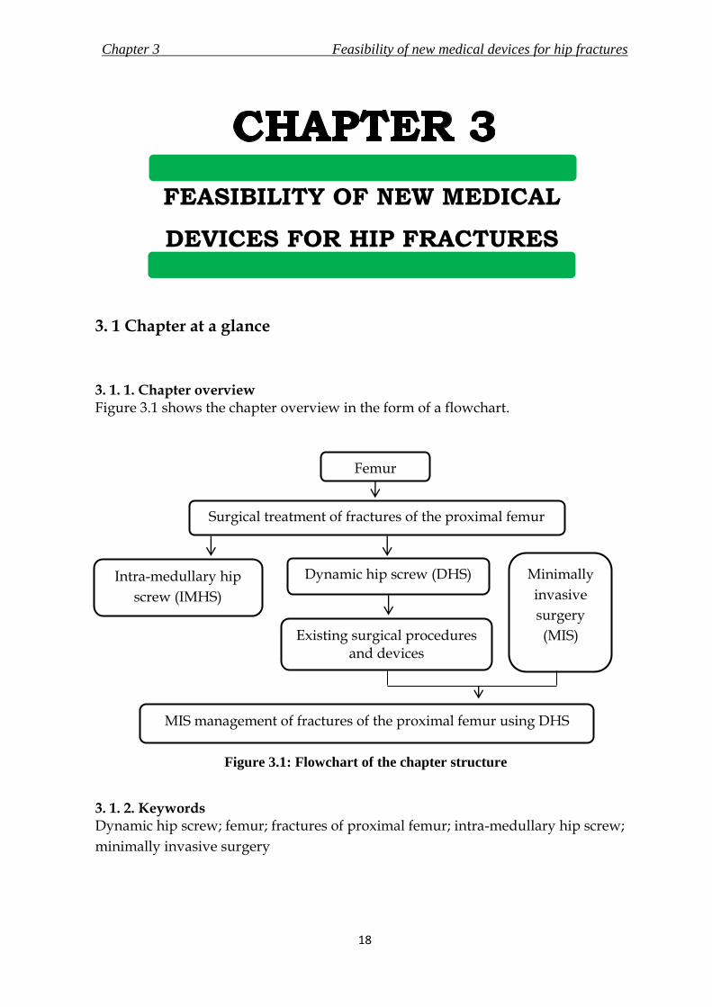
3. 1. 1. Chapter overview Figure 3.1 shows the chapter overview in the form of a flowchart.
Figure 3.1: Flowchart of the chapter structure
3. 1. 2. Keywords Dynamic hip screw; femur; fractures of proximal femur; intra-medullary hip screw;
minimally invasive surgery
Femur
Surgical treatment of fractures of the proximal femur
Dynamic hip screw (DHS)
Existing surgical procedures and devices
Intra-medullary hip
screw (IMHS)
Minimally
invasive
surgery
(MIS)
MIS management of fractures of the proximal femur using DHS

Chapter 3 Feasibility of new medical devices for hip fractures
19
3. 2. Introduction
Fractures of the proximal femur, more commonly known as hip fractures are
frequent injuries in the elderly (Canale, 2002); surgical management is considered
to be the standard treatment for these fractures (Ahn and Bernstein, 2010). Intra-
medullary devices or dynamic hip screws are used for surgical treatments of
fractures of the proximal femur. Amongst them the dynamic hip screw (DHS),
first introduced in 1941 by Dr. E. Pohl (Dittel and Rapp, 2008), is considered the
standard fixation device for the treatment of such fractures (Chirodian et al., 2005;
Harrington et al., 2002; Esser et al., 1986).
In recent years, there has been an increase in the popularity of minimally invasive
surgeries (MIS) due to apparent advantages to the hospital and patients. These
include relatively reduced perioperative blood loss, shorter hospital stay and
aesthetic appeal due to lesser scarring (Ho et al., 2008; Yeung, 2008; Lee et al., 2007).
The objective of this research was to design medical devices, which would aid the
implementation of MIS for the implantation of the DHS. A feasibility study for
new devices is important to identify the potential market share, similar devices
produced by competitor companies and the potential market value of devices
(Aitchison et al., 2009). The feasibility study presented in this chapter concluded
with the identification of devices that had to be redesigned/ developed to enable
MIS treatment of proximal femur fractures using the DHS.

Chapter 3 Feasibility of new medical devices for hip fractures
20
3. 3. The Femur
The femur, also called the thigh bone, is the longest, heaviest and one of the
strongest bones in the body. Studies and findings described by Standring (2008)
and Callaghan et al. (2007) were used to state the structure and function of the
femur that are discussed in this section, unless otherwise cited. It articulates with
the acetabulum of the pelvis (socket of the “ball – socket” hip joint) superiorly, and
with the tibia and the patella (knee cap) inferiorly, thus forming a part of both the
hip and the knee joint (Figure 3.2). The femur is the skeletal support for the thigh.
Figure 3.2: Location of femur relative to the bones of the lower extremity. Images of
pelvis and knee joint reproduced with kind permission from Sawchuck, L.A. and J.
Padiak, Department of Anthroplogy, University of Toronto, Scarborough

Chapter 3 Feasibility of new medical devices for hip fractures
21
The proximal end of the femur consists of a head, a neck, and a greater and lesser
trochanter. The neck connects the head to the trochanters and in turn to the shaft.
The femoral neck forms an angle of about 135 degrees with the shaft in adults. The
shaft of the femur is roughly cylindrical and inclines medially and downwards.
The shaft is broader at the extremities than in the centre, and is the broadest at the
distal extremity. The tibia and the fibula descends vertically from the knee joint to
the ankles, and hence the inclination in the shaft of the femur permits the ankles to
be aligned with the body. The various regions of femur are shown in Figure 3.3.
Figure 3.3: Anatomy of the femur. Images reproduced with kind permission from
Sawchuck, L.A. and J. Padiak, Department of Anthroplogy, University of Toronto,
Scarborough

Chapter 3 Feasibility of new medical devices for hip fractures
22
Bone can either be cortical or cancellous. Cortical, also known as compact bone,
comprises 80% of the human skeleton and is formed of tightly assembled osteons.
It is mainly found in the outer aspects of long bones. On the other hand,
cancellous (trabecular) bone is formed of less densely assembled osteons.
Cancellous bone is mainly found towards the ends of long bones (Tsiridis and
Schizas, 2008). Rho et al. (1993) has shown that the Young’s modulus of cortical
bone (18.6 ± 3.5 GPa) is relatively higher than that of cancellous bone (10.4 ± 3.5
GPa). The femoral shaft consists predominantly of cortical bone with a large
medullary cavity running axially along the length of the bone. The wall is thickest
at the middle of the shaft and gets thinner towards the extremities; and the cavity
is progressively filled with cancellous bone. The proximal and distal ends of the
femur have a thin shell of cortical bone with the cancellous bone arranged along
lines of greatest stress. The combination of spongy extremities and hard middle
allows the bone to transmit the forces of body weight and muscles efficiently.
The attributes and structure of the femur allow the bone to perform its significant
functions, which are to support and transmit the weight of the body and to assist
in gait.

Chapter 3 Feasibility of new medical devices for hip fractures
23
3. 4. Fractures of the Proximal Femur
3. 4. 1. Overview
The fractures of the proximal femur are the most frequent injuries in the elderly
population (Jewell et al., 2007). Along with the increase in life expectancy of the
world’s population, it is likely that the incidence of these fractures may keep
rising. The following sections discuss the classification and cause of the fracture,
and the statistics associated with the fracture.
3. 4. 2. Anatomical Locations of the Fractures
The fractures are divided into four main categories, classified by the region of the
femur affected. The information collected in this section was retrieved from a
publication by Evans and Mcgrory (2002) and from Campbell’s operative
orthopaedics 10th edition (Canale, 2002). A graphical representation of the
anatomic regions of the proximal femur relating to the areas of fractures is shown
in Figure 3.4.
i. Femoral neck fracture involves the fractures that occur between the femoral
head and the greater trochanter, and are prominent in elderly patients. The
fractures are intracapsular and the synovial fluid may interfere with the
healing. These fractures are either treated with insertion and placement of

Chapter 3 Feasibility of new medical devices for hip fractures
24
parallel cannulated screws to achieve compression and anatomic reduction or
by hermiarthroplasty of the hip, where only the ball (femoral head) of the hip
joint is replaced by an implant. The treatment of choice depends on the age of
the patient and the characteristics of the fracture.
Figure 3.4: Anatomical regions of the proximal femur.
ii. Greater trochanter fractures are not very common and are usually a cause of
direct trauma to the trochanter. A non-operative treatment, like the use of
crutches, is preferred for the management of these fractures.
iii. Intertrochanteric fracture involves the fractures in a line between the femoral
neck and the femoral shaft. They may involve both the trochanters. These
fractures are classified based on the stability of the fracture pattern and usually
occur in patients over 70 years of age. Surgery is the treatment of choice and the
dynamic hip screw is the most common form of fixation device used.

Chapter 3 Feasibility of new medical devices for hip fractures
25
iv. Subtrochanteric fractures occur between the lesser trochanter and the isthmus
of the diaphysis (shaft) of the femur. These fractures have a bimodal age
distribution and can be treated operatively or non-operatively.
3. 4. 3. Cause of the fracture
Femoral fractures in young patients are rare and mostly are a result of high energy
physical traumas like car accidents, whereas in the elderly population it is a very
frequent injury and is caused due to low impact accidents like falls (Holt et al.,
2008; Marks, 2010). Age is a major factor for the fracture as the bone mineral
density decreases with increasing age, leading to a weaker bone (Evans and
Mcgrory, 2002). Sex, apart from age, is another major risk factor for hip fractures,
as post-menopausal women are more prone to osteoporosis, which causes weaker
bones; resulting in the risk of fracture being 2 to 3 times higher than in men
(Marks, 2010). Other factors that cause hip fractures include ethnicity,
malnutrition, less physical activity, low body mass index, smoking, and excessive
intake of caffeine and alcohol. The fractures are frequently pathologic in the
elderly (Lefauveau and Fardellone, 2004).
3. 4. 4. Epidemiology of the fracture
Hip fractures represent a substantial burden socially, medically and financially,
and studies suggest a steady increase in hip fractures along with the ageing

Chapter 3 Feasibility of new medical devices for hip fractures
26
population. The lifetime risk of a hip fracture in industrialised nations is 15 to 17%
for women and 5 to 6% for men (Wong et al., 2009; Jewell et al., 2007; Van Staa et
al., 2001). The risk of enduring a hip fracture doubles every decade after the age of
50 years in both men and women (Evans and Mcgrory, 2002). There are 250,000 to
300,000 hip fractures annually and account for 30% of all hospitalised patients in
the USA (Aros et al., 2008; Wiss, 2001)
There were 1.6 million cases worldwide and 560,000 cases in Europe in 1992
(Lefauveau and Fardellone, 2004). Medicare cost for hip fractures in 1991 in the
USA was estimated at $2.9 billion, and the cost was estimated at $16 billion in 2001
(Lee et al., 2007). It has been estimated that it may affect 117,000 people in the UK
in the year 2016 (Wiss, 2001), and the worldwide incidences have been predicted
to rise to 6.26 million by 2050 (Evan and Mcgrory, 2002). The epidemiology of hip
fractures is shown in Figure 3.5.
Intertrochanteric fractures account for approximately 50% of the proximal femoral
fractures in the elderly (Peyser et al., 2005; Gotfried, 2000). They usually occur in
patients over 70 years of age. Subtrochanteric fractures appear commonly in
patients between 20 to 40 years of age and in those over 60 years of age (Canale,
2002).

Chapter 3 Feasibility of new medical devices for hip fractures
27
Figure 3.5: Epidemiology of hip fractures – a) Geographical distribution, b) sex-wise
distribution, and c) age wise distribution. Royalty free image of world map courtesy of
Maps for design (www.mapsfordesign.com)

Chapter 3 Feasibility of new medical devices for hip fractures
28
3. 4. 5. Morbidity and mortality due to the fracture
Hip fractures are associated with a high rate of mortality and morbidity, with
mortality ranging from 11% to 23% after six months, and 22% to 29% after a year
(Haleem et al., 2008; Jewell et al., 2008; Roder et al., 2003); the rate increases with
the age at which the fracture was sustained. The mortality rates due to
intertrochanteric femoral fractures range from 15% to 20%. However, after a year,
it seems that the rate adjusts as per the age of the patient (Canale, 2002).
3. 5. Treatment of Intertrochanteric Fractures of the Proximal Femur
3. 5. 1. Overview
The purpose of hip fracture treatment is to alleviate pain and to achieve maximum
possible anatomical union of the fracture to assist restoration of the patient’s lower
extremity to pre-injury activity level. Surgery is considered to be the standard
treatment for management of intertrochanteric fractures. Surgical treatment allows
for early mobilization of the patient, with partial weight-bearing, as well as
reducing mortality and morbidity (Steinberg et al., 2005).
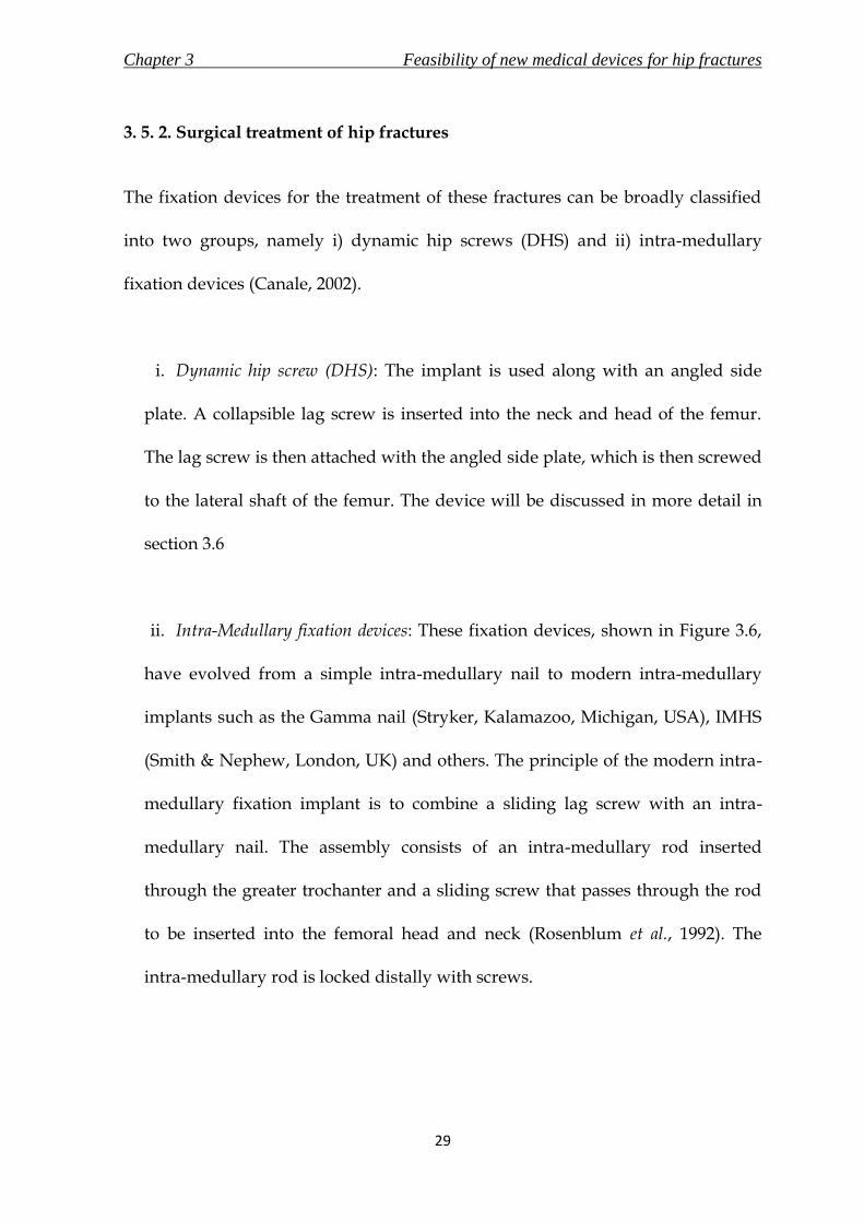
Chapter 3 Feasibility of new medical devices for hip fractures
29
3. 5. 2. Surgical treatment of hip fractures
The fixation devices for the treatment of these fractures can be broadly classified
into two groups, namely i) dynamic hip screws (DHS) and ii) intra-medullary
fixation devices (Canale, 2002).
i. Dynamic hip screw (DHS): The implant is used along with an angled side
plate. A collapsible lag screw is inserted into the neck and head of the femur.
The lag screw is then attached with the angled side plate, which is then screwed
to the lateral shaft of the femur. The device will be discussed in more detail in
section 3.6
ii. Intra-Medullary fixation devices: These fixation devices, shown in Figure 3.6,
have evolved from a simple intra-medullary nail to modern intra-medullary
implants such as the Gamma nail (Stryker, Kalamazoo, Michigan, USA), IMHS
(Smith & Nephew, London, UK) and others. The principle of the modern intra-
medullary fixation implant is to combine a sliding lag screw with an intra-
medullary nail. The assembly consists of an intra-medullary rod inserted
through the greater trochanter and a sliding screw that passes through the rod
to be inserted into the femoral head and neck (Rosenblum et al., 1992). The
intra-medullary rod is locked distally with screws.
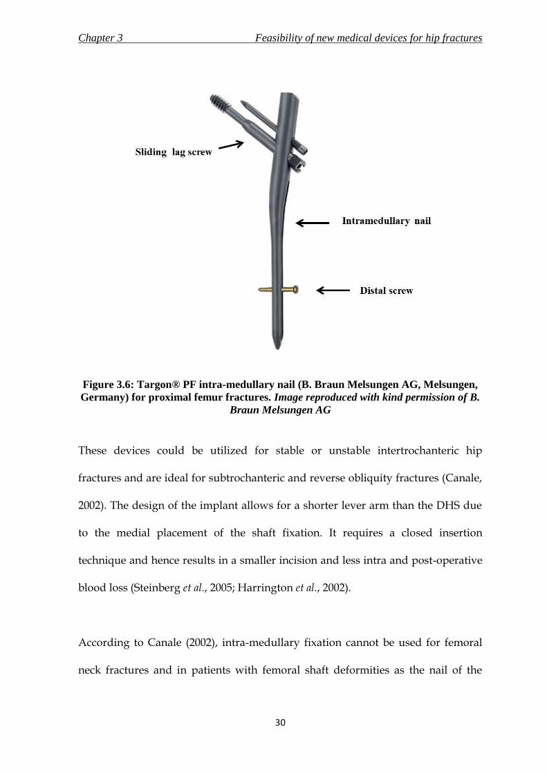
Chapter 3 Feasibility of new medical devices for hip fractures
30
Figure 3.6: Targon® PF intra-medullary nail (B. Braun Melsungen AG, Melsungen,
Germany) for proximal femur fractures. Image reproduced with kind permission of B.
Braun Melsungen AG
These devices could be utilized for stable or unstable intertrochanteric hip
fractures and are ideal for subtrochanteric and reverse obliquity fractures (Canale,
2002). The design of the implant allows for a shorter lever arm than the DHS due
to the medial placement of the shaft fixation. It requires a closed insertion
technique and hence results in a smaller incision and less intra and post-operative
blood loss (Steinberg et al., 2005; Harrington et al., 2002).
According to Canale (2002), intra-medullary fixation cannot be used for femoral
neck fractures and in patients with femoral shaft deformities as the nail of the

Chapter 3 Feasibility of new medical devices for hip fractures
31
implant needs to be inserted into the medullary canal of the shaft, which may
cause further injuries. The implant is also not recommended for younger patients
as it requires a large amount of cancellous bone to be removed from the
trochanteric block. The insertion of the nail into the medullary cavity could result
in trauma for the bone and could lead to further fractures. Canale (2002) also
reports a complication rate of 3% to 6% of secondary fractures of the femoral shaft
during the insertion of these devices and the surgery is also regarded as a more
technically demanding procedure for the surgeon.
3. 5. 3. Intra-Medullary or DHS?
The two fixation methods to treat the fractures of the proximal femur offer their
own sets of advantages. Although intra-medullary fixation offers biological
benefits due to the percutaneous method of implantation, the DHS implant has a
simpler surgical technique for insertion (Canale, 2002). Butt et al. (1995) reported
no significant difference in operating time and blood loss in their study to evaluate
the difference between a DHS and a Gamma nail. In addition, no significant
differences were recorded for the time the fracture took to heal. However, it has
been discovered that in some cases, intra-medullary fixation causes secondary
fracture of the shaft of the femur (Aros et al., 2008; Harrington et al., 2001; Butt et
al., 1995). The DHS surgical technique is also a bone-saving procedure as the
stabilising plate is fixed to the exterior of the bone. In comparison, intra-medullary
implants cause damage to the cancellous bone. Trials conducted by Parker and

Chapter 3 Feasibility of new medical devices for hip fractures
32
Handoll (2009) concluded that the DHS had lower complication rates than that of
intra-medullary nails. However, intra-medullary fixations are preferred to the
DHS for unstable trochanteric fractures, subtrochanteric fractures and reverse
obliquity fractures (Hamilton and Kelly, 2003). There are continual improvements
in both types of fixation, but as indicated by the literature, currently the dynamic
hip screw is the standard and most common type of fixation for intertrochanteric
fractures.
3. 6. Dynamic Hip Screw (DHS)
3. 6. 1. The implant
The DHS, also called the sliding hip screw, is an extra-medullary fixation device
used for the treatment of fractures of the proximal femur. The DHS assembly
consists of a lag screw and a side plate. The fundamental principle of this implant
is to promote compression of the fractured bone fragments by allowing the lag
screw, inserted into the femoral head, to form a sliding connection with side plate
attached to the lateral femoral shaft. The impaction increases bone-on-bone
contact, which aids in healing while decreasing implant stress (Evans and
McGrory, 2002). The screw/plate angle is selected depending on the femoral
anatomy of the patient and the type of fracture. The implant also provides
rotational stability to the fracture as the lag screw is unable to rotate within the
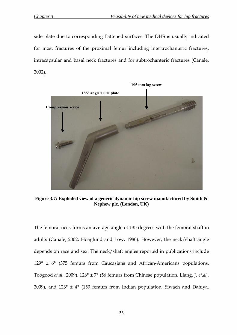
Chapter 3 Feasibility of new medical devices for hip fractures
33
side plate due to corresponding flattened surfaces. The DHS is usually indicated
for most fractures of the proximal femur including intertrochanteric fractures,
intracapsular and basal neck fractures and for subtrochanteric fractures (Canale,
2002).
Figure 3.7: Exploded view of a generic dynamic hip screw manufactured by Smith &
Nephew plc. (London, UK)
The femoral neck forms an average angle of 135 degrees with the femoral shaft in
adults (Canale, 2002; Hoaglund and Low, 1980). However, the neck/shaft angle
depends on race and sex. The neck/shaft angles reported in publications include
129° ± 6° (375 femurs from Caucasians and African-Americans populations,
Toogood et.al., 2009), 126° ± 7° (56 femurs from Chinese population, Liang, J. et.al.,
2009), and 123° ± 4° (150 femurs from Indian population, Siwach and Dahiya,

Chapter 3 Feasibility of new medical devices for hip fractures
34
2003). The angled side plate of the generic DHS is supplied in angles of 120
degrees to 150 degrees in increments of 5 degrees to cater to the differing
neck/shaft angles of the global population. Although newer implant - Gotfried
PC.C.P. (section 3.8.2) only caters to the most common angle (135 degrees), it is
criticised for not offering variability in the neck/shaft angle (Peyser et.al., 2005).
The failure rate of DHS has been reported to range from 16 % to 23% (Kumar et al.,
2007; Gundle et al., 1995). The implant requires adequate purchase in the bone for
the fixation to be stable, and hence the position of the lag screw in the femoral
head and strength of the cancellous bone is crucial (Gundle et al., 1995;
Baumgaertner et al., 1995). Osteoporotic bones and incorrect placement of the lag
screw are two factors that may cause cut-out of the screw from the femoral head
(Evans and McGrory, 2002). Screw cut-out is the most common cause of failure of
fixation and incidence rates have been reported to range from 5.3% to 16.8%
(Kumar et al., 2007). The complications of the DHS also include non-union,
shortening of the affected limb, and displacement of fracture (Laohapoonrungsee
et al., 2005; Peyser et al., 2005; Kim et al., 2001). Causes of these complications
could be excessive slide of the lag screw and/or lack of anatomic reduction. Kim et
al. (2001) suggested that the instability of the fracture is the most important cause
of fixation failure. Nevertheless, DHS is currently considered the standard device
for the treatment of fractures of the proximal femur.

Chapter 3 Feasibility of new medical devices for hip fractures
35
3. 6. 2. Evolution of the DHS implant
Surgical fixation of proximal femur fractures gained popularity with the
introduction of the tri-flanged nail by M. Smith Peterson in 1931. The design was
enhanced in 1941 by Jewett, when the femoral nail was given a rigid connection
with a plate attached to the lateral side of the femur. The high rate of
complications concerning this design and parallel developments of the era by
Thornton (also with a rigid connection) included leg length discrepancy and
external rotation. The data on the evolution of the DHS implant was taken from a
publication by Dittel and Rapp (2008) and the timeline is shown in Figure 3.8.
Figure 3.8: Timeline of evolution of DHS
The first implant with the principle of a sliding connection between the femoral
nail and side plate was designed and introduced by Ernst Pohl in 1951. The design

Chapter 3 Feasibility of new medical devices for hip fractures
36
is the basis of the DHS implants till date and the design has not evolved much
from the original. The design was improved in 1979 by AO (Davos, Switzerland).
The round cross-section of the lag screw was replaced by a lag screw which had
been flattened on the sides; the barrel was also flattened on two sides to provide
corresponding sliding surfaces. This design augmented the rotational stability of
the implant.
Since the introduction of the DHS, there have been some modified versions of the
basic principle like the DHS with a Medoff plate, Gotfried PCCP and the Double
Dynamic Martin screw. The generic DHS is still the preferred implant because of
its simple surgical technique and promising results.
3. 6. 3. Surgical procedure for implanting a DHS implant
3. 6. 3. 1. Surgical instruments
There are seven key instruments used during the implantation of a DHS using the
conventional surgical procedure. The functions of the instruments were taken
from Campbell’s Operative Orthopaedics (Canale, 2002) and the surgical
technique manual for compression hip screw plates (Smith & Nephew plc.,
London, UK). The instruments are shown in Figures 3.9 to 3.15, and were all
manufactured by Sushrut Surgicals Pvt. Ltd. (Pune, Maharashtra, India)

Chapter 3 Feasibility of new medical devices for hip fractures
37
i. Angle guide (Figure 3.9) is temporarily attached to the upper end of the
femur, to accurately provide both horizontal and vertical reference required by
the surgeon to insert the guide pin into the femoral head.
Figure 3.9: Generic DHS angle guide
ii. Guide pin (Figure 3.10) is inserted at the start of the surgery, and is retained
until the end of the surgical procedure. It acts as a guide regarding the angle
and the length required of the lag screw. It also serves a secondary purpose of
reducing the fracture at the start of the surgery.
Figure 3.10: Guide pins (diameter – 3mm)

Chapter 3 Feasibility of new medical devices for hip fractures
38
iii. Measuring gauge (Figure 3.11) is used to measure the length of the lag screw
required.
Figure 3.11: Generic measuring gauge
iv. Triple reamer (Figure 3.12) is length-adjustable, and is used to make a tunnel
where the lag screw and the angle plate are later placed in. The triple reamer is
a special drill which would create a tunnel with three different diameters - one
for the screw, one for the plate barrel and one for the junctions between the
plate and the barrel.
Figure 3.12: Generic triple reamer to make tunnel of three different diameters
v. Tap (Figure 3.13): tapping is an optional step during the procedure and is
not deemed necessary in osteoporotic bones. This is because the lag screw will
be able to cut through the softer bone without any need of excess force.

Chapter 3 Feasibility of new medical devices for hip fractures
39
However, it is required in younger patients and cases with strong bones, to
avoid torque exertion on the insertion wrench and rotation of the fracture.
Figure 3.13: Generic tap
vi. Insertion wrench (Figure 3.14) is used to assemble the lag screw, centre
sleeve and angle plate to be inserted into the femur.
Figure 3.14: Generic insertion wrench
vii. T-handle (Figure 3.15) is detachable and is used at various points of the
surgery. First, it is used to hold the angle guide and later, to insert the lag
screw.
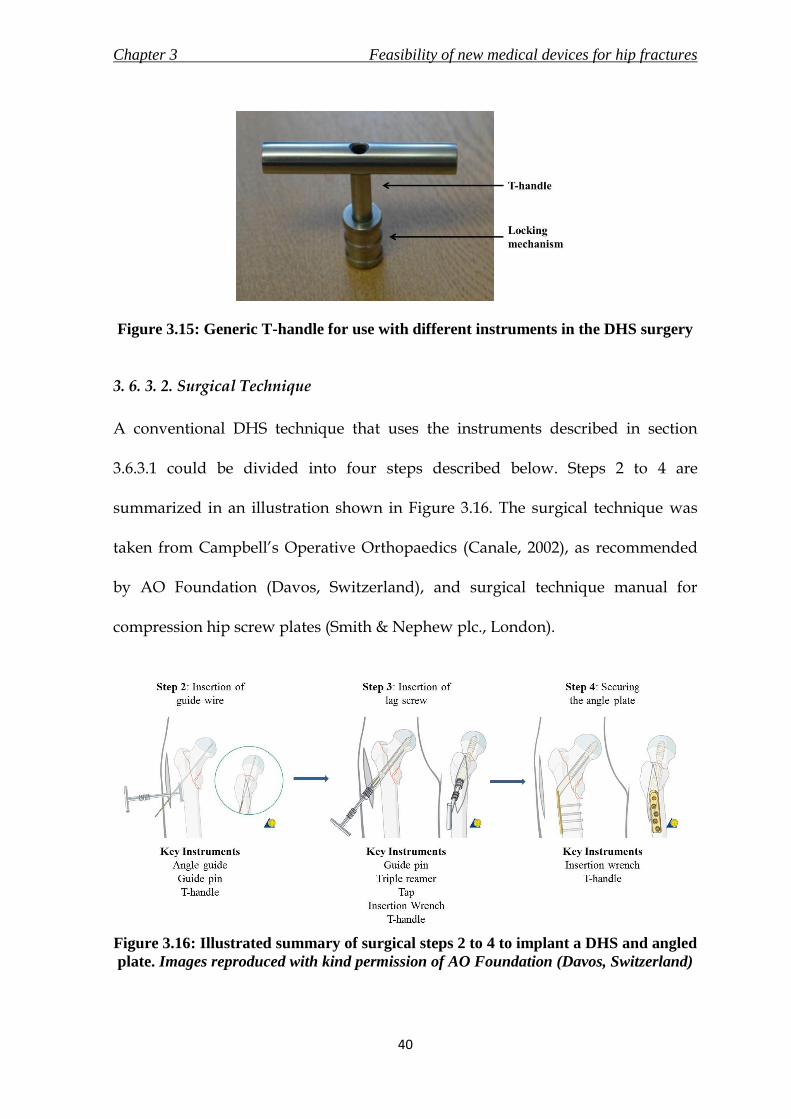
Chapter 3 Feasibility of new medical devices for hip fractures
40
Figure 3.15: Generic T-handle for use with different instruments in the DHS surgery
3. 6. 3. 2. Surgical Technique
A conventional DHS technique that uses the instruments described in section
3.6.3.1 could be divided into four steps described below. Steps 2 to 4 are
summarized in an illustration shown in Figure 3.16. The surgical technique was
taken from Campbell’s Operative Orthopaedics (Canale, 2002), as recommended
by AO Foundation (Davos, Switzerland), and surgical technique manual for
compression hip screw plates (Smith & Nephew plc., London).
Figure 3.16: Illustrated summary of surgical steps 2 to 4 to implant a DHS and angled
plate. Images reproduced with kind permission of AO Foundation (Davos, Switzerland)

Chapter 3 Feasibility of new medical devices for hip fractures
41
i. Reduction and exposure: the patient is anaesthetised and placed in a supine
position. The legs are also placed in a traction extension. A closed reduction is
performed on the fracture. An incision is then made extending distally from the
greater trochanter. The length of the incision, generally between 100 and 150
mm, depends on the length of the side plate being used. The fracture is then
reduced with the traction extensions.
ii. Placing the guide wire and determination of length of screw: the angle of
insertion of the guide pin varies with the angle of the plate to be used, which is
decided prior to the surgery. The 135 degrees angle plate is most commonly
used for these surgeries, and thus they will be used to describe the rest of the
procedure. A good point to locate the entry of the guide wire is approximately
20 mm below the vastus lateralis ridge (inferior border of the greater trochanter),
as shown in Figure 3.17. The entrance site is moved 5 mm distally for each 5
degrees increase in the barrel angle thereof. The guide pin is then inserted into
the femoral head using a Fixed Angle Guide.
The depth of the guide pin inserted is measured using a measuring gauge, and
then a lag screw which is 10 mm shorter than the reading is selected. (For
example, if the measuring gauge reads 115 mm, then the lag screw should be
105 mm.)

Chapter 3 Feasibility of new medical devices for hip fractures
42
Figure 3.17: Insertion point of guide pin in context to vastus lateralis
iii. Insertion of the DHS screw: once the guide wire is in place, the DHS triple
reamer is used to make a tunnel. This reamer creates a tunnel with three
different diameters, i.e. one for the screw, one for the plate barrel and one for
the junctions between the plate and the barrel. The tunnel is then tapped, if
deemed necessary, to avoid excess torque application while inserting the screw.
It is usually advisable to tap in younger patients as the bone is much stronger.
The screw is then inserted using a wrench and centring T-handle. The plate can
only be installed and aligned correctly if the T-handle is turned perpendicular
to the axis of the femoral shaft at the end of this step.
iv. Mounting and securing the plate: once the screw is set in place, the DHS plate
on the insertion wrench is slid over the guide wire. The guide wire can now be
removed. The plate is hammered into the tunnel with an instrument called the
DHS impactor. The plate is then secured distally with a number of cortex
screws of required lengths. The fracture can also be compressed by inserting a
compression screw at this point. However, the compression screw could be

Chapter 3 Feasibility of new medical devices for hip fractures
43
avoided as the sliding mechanism of the implant will allow the fracture to
impact and compress as the patient bears weight.
3. 7. Minimally Invasive Surgeries (MIS)
There has been an increase in popularity of minimally invasive surgeries in recent
years. The foremost purpose of a MIS is to promote or maintain the benefits of an
existing surgical treatment while combining the advantages of a smaller incision.
The advantages of a smaller incision are aesthetical, biological and commercial,
which may include reduction in soft tissue trauma surrounding the fracture repair
site, relatively less perioperative blood loss and better cosmetic results to the
patient due to reduced scarring. (Chong et al., 2006) Other benefits of the less
invasive technique also include reduced post-operative pain and reduced
morbidity (Ho et al., 2008; Peyser et al., 2005). All these advantages could lead to
reduced hospital stay, which may be beneficial to the patient and reduce the
hospital costs.
A prominent criticism against MIS is the learning curve for the surgeons. Teaching
of the new techniques could not only lead to a relatively greater rate of
complications initially, but also prove difficult to learn due to the reduced
visibility and feedback signals (Scuderi and Tria, 2010). MIS is a relatively new
innovation in the surgical field and the concerns stated could be solved with
developments in surgical techniques and implant designs.

Chapter 3 Feasibility of new medical devices for hip fractures
44
MIS procedures vary according to the medical discipline. However, for broad
classification, the author of this thesis has divided them into two categories of
surgical approaches – Alternative and Similar. Alternative surgical approaches,
like the recently developed two-incision hip replacement techniques or robotic
surgeries involves an entirely new surgical procedure, implant and associated
instruments to facilitate a small incision entry for the treatment of the injury.
Similar surgical approach attempts to emulate the existing surgical procedure with
minor modifications and may also include amendments to the design of the
implant and/or inclusion of new instruments to achieve implantation through a
smaller incision.
3. 8. Review of existing MIS techniques for proximal femur fractures
3. 8. 1. Overview
DHS as the standard choice and the rising popularity of MIS procedures have
encouraged proximal femur fracture treatment techniques discussed in this
section. They were grouped according to their surgical approach. It should be
noted that intra-medullary devices can be considered as MIS option for treatment
of proximal femur fractures. However, the following review is intended to discuss
the MIS options that are based or were initiated by the principle of the DHS
implant.

Chapter 3 Feasibility of new medical devices for hip fractures
45
3. 8. 2. Alternative Surgical Approach
The devices mentioned in this section were developed using the sliding principle
of DHS and are indicated for fracture management of the proximal femur. The
devices mentioned in this section are compared with the generic DHS implant to
form a competitor review in Table 3.1
i. Mini invasive screw system (MISS) is a three part implant system consisting of a
long five-hole femoral plate, a large cephalic screw and a barrel which is locked
on to the femoral plate to allow the screw a maximum slide of 15 mm once
implanted. The incision required to implant the device is 50 mm to 70 mm long
(Burdin et al., 2006)
ii. Percutaneous compression plate (PC.C.P.) was introduced by Gotfried in the
late 1990 (Gotfried, 2000). The wide range of studies (Peyser et al., 2007; Brandt et
al., 2006; Peyser et al., 2005) conducted on the device suggests the popularity it
has gained over a short period. The device consists of a femoral plate which is
first introduced to slide along the femoral shaft. This is followed by insertion of
two telescoping neck screws into the femoral neck and head to compress the
fracture. The device requires two incisions of 20 mm each for implantation. The
purpose of two neck screws is to provide rotational stability to the fracture
(Gotfried, 2000). The device is superior to the DHS in terms of blood loss, soft
tissue healing and operation time and similar in terms of fracture stability and
device failure. However, the device demands a steep learning curve as the

Chapter 3 Feasibility of new medical devices for hip fractures
46
surgical procedure is perceived as technically demanding (Peyser et al., 2005).
The device also requires new instruments and other inventory and hence may
not prove cost effective for the hospital until it is selected as the standard implant
for the treatment of fractures of the proximal femur.
Figure 3.18: Gotfried PC.C.P (Orthofix srl, Italy). Image reproduced with kind
permission of Orthofix srl.
iii. The Targon® FN (B. Braun Melsungen AG, Melsungen, Germany) implant,
made of titanium alloy, consists of a small femoral plate with six locking screw
holes. The two distal holes fix the plate onto the femoral shaft. The proximal
holes allow four telescoping sliding screws to be advanced into the femoral head.
The device requires a special rig for insertion of the implant, and needs 60 mm of
incision for insertion (Brandt et al., 2010). The information was also collected
personally by the author at the product launch held at Stamford, UK in October
2007.

Chapter 3 Feasibility of new medical devices for hip fractures
47
Figure 3.19: Targon® FN (B. Braun Melsungen AG, Melsungen, Germany) for
proximal femur fractures. Image reproduced with kind permission of B. Braun
Melsungen AG
3. 8. 3. Similar Surgical Approach
The similar surgical approaches practiced at present, attempts minor
modifications to the actual surgical approach to perform a smaller incision while
using existing fixation devices. This requires a smaller learning curve and prevents
stocking of new equipment. It could possibly promote faster inclusion of a
minimally invasive approach and their advantages to the surgical treatment. A
review of current surgical techniques presented procedures which could be
broadly classified into two kinds – with and without the use of angle guide.

Chapter 3 Feasibility of new medical devices for hip fractures
48
i. With angle guide: the minimally invasive surgeries conducted with an angle
guide included trials by Ho et al. (2008), and by Leung and Tsang (2008). The
incision used in these procedures ranged from 40 mm to 50 mm in length. The
lag screw is advanced after the insertion of the guide wire, as with the
conventional procedure. The side plate is inserted with the barrel facing
laterally and then rotated until it lies under the skin and the fascia. The skin is
retracted to secure the plate with distal screws. The deep layer and skin incision
closure are performed in the usual fashion.
ii. Without angle guide: the distance between the front end and bar of the
generic angle guide is 40 mm (Leung and Tsang, 2008), and thus it is the
minimum required incision for utilizing this instrument during the surgery.
The function of the angle guide to insert the guide wire at an angle of 135
degrees or as required based on the patient’s anatomy, could be performed by
use of fluoroscopy and estimation using landmarks (Waters et al., 2006). This
would enable the incision to be reduced to a range of 20 mm to 30 mm. This
review included trials by Wong et al. (2009), Lee et al. (2007) and Waters et al.
(2006). All the studies reviewed inserted the guide wire percutaneously by
placing the angle guide parallel to the femoral shaft externally and then using
fluoroscopy imaging to ensure satisfactory alignment. The incision is made
distally from the guide wire. The remaining procedure is the same as
mentioned previously with the use of an angle guide.

Chapter 3 Feasibility of new medical devices for hip fractures
49
Table 3.1: Comparison of implants
Generic DHS
implant Gotfried PC.C.P. Targon FN
Manufacturer
Many including
Smith & Nephew plc
(London, UK) and
Synthes GmbH
(Solothurn,
Switzerland)
Orthofix srl, Italy
B. Braun Melsungen
AG, Melsungen,
Germany
Year of
Introduction
Previous generic
design update in 1979 Late 1990's 2007
Incision
Length 100 mm to 150 mm
Two incisions of 20
mm each 60 mm
List of
Components
a) Lag screw, b)
angled side plate, and
c) optional
compression screw.
a) Side plate with
angled slots, and b) 2
× telescoping screws
a) Side plate with
angled slots, and b) 4
× telescoping screws
Material of
construction Stainless Steel NA
Titanium alloy
Ti6Al4V
Type of
fixation screw
Cylindrical lag screw
with flattened sides to
avoid rotation
Cylindrical
telescoping screws
Cylindrical
telescoping screws
with maximum slide
of 20 mm
Note: Rotation controlled with multiple screws
Range of
fixation screw
lengths
55 mm to 140 mm in
increments of 5 mm
90 mm to 140 mm in
increments of 10 mm
70 mm to 110 mm in
increments of 10 mm
Type of side
plate
Fixed angle side plate
with barrel and 2-14
distal slots for shaft
screws
Side plate with two
angled slots for
telescoping screws
and three distal screw
holes for shaft screws
Side plate with four
angled screw holes
for telescoping
screws and two distal
screw holes for shaft
screws
Range of side
plate angles
120 degrees to 150
degrees in increments
of 5 degrees
Only 135 degrees Only 130 degrees

Chapter 3 Feasibility of new medical devices for hip fractures
50
Generic DHS
implant Gotfried PC.C.P. Targon FN
Advantages
Simple surgical
technique
Minimally invasive
procedure
Minimally invasive
procedure
Consistent positive
results over the last
four decades of use
Provides additional
rotational stability
Provides additional
rotational stability
Reduced inventory
cost (associated
instruments) to the
hospitals
No lateral protrusion
due to telescoping
nature of the fixation
screw
Limited sliding of 20
mm prevents lateral
protrusion of the
fixation screw
Disadvantages
Large incision
causing relatively
more blood loss and
soft tissue damage
Technically
demanding surgical
procedure
Technically
demanding surgical
procedure
Lateral protrusion of
the fixation screw is
possible - may lead to
complications and
failure of fracture
treatment
Additional expense to
the hospitals due to
the need of procuring
new associated
instruments including
extensive assembling
jigs
Additional expense to
the hospitals due to
the need of procuring
new associated
instruments including
extensive assembling
jigs
No variability in the
neck/shaft angle
No variability in the
neck/shaft angle

Chapter 3 Feasibility of new medical devices for hip fractures
51
3.9. Identified medical devices for MIS of DHS
3. 9. 1. Overview
The standard fixation device for the treatment of proximal femur fractures is
considered to be the DHS, as discussed in this chapter. It was also realised that
proximal femur fractures are very common injuries and represent a significant
financial burden to the society.
With the rise of MIS as a surgical option, the new devices and instruments are
increasingly permitting the smallest incision possible. The new implants and
techniques discussed in section 3.8 allow for incision lengths in the range of 20
mm to 60 mm as compared to the incision length of 100 mm to 150 mm required
by the conventional surgical technique of implanting the generic design of DHS.
However, it was also noted in section 3.5.3 and 3.6.1 that the popularity of DHS is
also due to the simplicity of the surgical procedure. The implants introduced in
section 3.8 to reduce the incision size require new instruments and a new surgical
procedure. The change does not only require an increase in hospital inventory but
also challenges the surgical technique that has been established for over four
decades, thus requiring a steep learning curve for the surgeons. Although the
techniques shown in similar surgical approaches (section 3.8.3) did exercise an
incision length of only 20 mm, the use of an angle guide was compromised to
achieve the small incision. It is also assumed by the author of this thesis that the

Chapter 3 Feasibility of new medical devices for hip fractures
52
surgeon would have to be thoroughly experienced to practice the similar surgical
approaches discussed in section 3.8.3.
3. 9. 2. Design Brief
The points discussed above were taken into consideration to define the objectives
to ensure that the newly developed medical devices from this research would be
accepted by the market and also successfully aid in treating the fractures of the
proximal femur. The design objectives of each medical device to be developed will
be discussed at the beginning of the respective design process. The general
guidelines set for the new medical devices are stated below.
i. The medical device(s) should aid in conducting a MIS approach to treat
fractures of the proximal femur with an incision of not more than 30 mm in
length.
ii. The devices should facilitate the use of a surgical approach, which would
be similar to the conventional method used to implant the DHS.
Based on the guidelines and on the surgical technique used to implant the DHS,
the medical devices that were identified to allow MIS of DHS were – i) the angle
guide, ii) the T-handle, and iii) the implant comprising of the DHS lag screw and
the angled side plate.

Chapter 3 Feasibility of new medical devices for hip fractures
53
The angle guide was chosen as it was discovered to be the only device due to
which the incision in the conventional procedure could not be reduced to less than
40 mm. The T-handle would be redesigned to be ergonomic and comfortable for
the surgeon to use. The new implant would utilise the same principle as the DHS
and a similar surgical approach. However, it would allow easier insertion through
an incision length of 30 mm or less without the requirement of a steep learning
curve for the surgeons.
The goal of the design process was to allow the use of the new angle guide and the
new T-handle with the existing set of instruments to insert the existing generic
DHS implant using the conventional surgical procedure; also to be able to use the
new angle guide and the new T-handle with the existing set of instruments to
insert the new implant using a similar approach.
3. 9. 3. Product Design Specifications of the Identified Medical Devices
Product design specification (PDS) was developed for the three identified medical
devices – (i) angle guide, (ii) T-handle and (iii) implant. The PDS, along with
relevant generic aspects of a PDS – performance, ergonomics, competition, etc.
(Childs, 2004), also considered the general requirements of surgical implants and
associated instruments specified in standards BS EN ISO 12011 (1998), BS EN ISO
14630 (2009), BS EN ISO 14602 (2010) and BS 3531-15 (1992). The specifications
were generated following literature research and expert opinion from Prof. N.
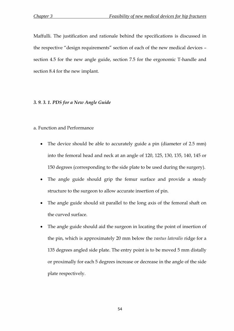
Chapter 3 Feasibility of new medical devices for hip fractures
54
Maffulli. The justification and rationale behind the specifications is discussed in
the respective “design requirements” section of each of the new medical devices –
section 4.5 for the new angle guide, section 7.5 for the ergonomic T-handle and
section 8.4 for the new implant.
3. 9. 3. 1. PDS for a New Angle Guide
a. Function and Performance
The device should be able to accurately guide a pin (diameter of 2.5 mm)
into the femoral head and neck at an angle of 120, 125, 130, 135, 140, 145 or
150 degrees (corresponding to the side plate to be used during the surgery).
The angle guide should grip the femur surface and provide a steady
structure to the surgeon to allow accurate insertion of pin.
The angle guide should sit parallel to the long axis of the femoral shaft on
the curved surface.
The angle guide should aid the surgeon in locating the point of insertion of
the pin, which is approximately 20 mm below the vastus lateralis ridge for a
135 degrees angled side plate. The entry point is to be moved 5 mm distally
or proximally for each 5 degrees increase or decrease in the angle of the side
plate respectively.

Chapter 3 Feasibility of new medical devices for hip fractures
55
The angle guide should not require an incision length of more than 30 mm
to perform the function.
The angle guide should be able to withstand a compressive force of 222 N
due to the surgeon pushing the device against the femoral shaft surface;
compressive force of 4 N due to the weight of the muscles and soft tissues.
The device should be designed for both single-use and re-use markets.
b. Environment
The angle guide will be used in a sterile environment. The device should
not retain appreciable residue such as blood or bone fragments in gaps
during operation.
During surgery, the angle guide will be placed on the curved femoral shaft
surface. The angle guide should not cause injuries to the muscles or soft
tissues surrounding the device when it is being inserted.
c. Material
The angle guide should be made of material which is biocompatible, and is
able to withstand sterilisation through steam or irradiation.
The material should have more than required ultimate tensile strength to
withstand the loading the angle guide will endure while in use.
The base material interfacing with the femoral shaft surface will have to
provide a steady grip without causing damage (scratching or digging into)
the bone.

Chapter 3 Feasibility of new medical devices for hip fractures
56
d. Sterilisation
The instrument should be sterilised prior to use, with steam in a single-use,
and using irradiation in a re-use market.
e. Packaging
The packaging will be sealed air-tight in a double pack to prevent any
contamination during transportation. It should clearly state the
environmental conditions necessary during transportation to avoid
damage.
It should be possible to open the packaging without use of instruments
such as knife or scissors.
The packaging will be clearly labelled with the instrument description and
material. The labels will also state the manufacturer’s name and contact
details, along with the necessary testing and approval mark. The packaging
should specify whether the device is for single-use or re-use.
f. Shape and Dimensions
The shape and dimensions of the design of the new angle guide should not
require an incision length of more than 30 mm for insertion and use.
The angle guide should allow a pin of 2.5 mm to pass through its tube for
insertion into the femoral head and neck.

Chapter 3 Feasibility of new medical devices for hip fractures
57
The base plate will be in contact with a curved surface with a radius of
curvature in the range of 13 mm to 18 mm. The base plate should grip and
form a steady construct on top of the curved surface.
g. Ergonomics
The design of the new angle guide should allow comfortable use by a
surgeon with one hand of either handedness.
The front end of the base plate should be tapered to slide through soft
tissues and muscles layer during insertion.
The surgeon should not “sense” any bending of the angle guide while
pushing it against the bone surface during use.
If the new design consists of an assembly, the individual components
should form a sturdy construct.
The product should not have any sharp edges to injure the patient, surgeon
or the surgical staff.
h. Customers
The customer will be orthopaedic surgeons, who will be utilising the angle
guide during surgical implantation of the DHS. The angle guide will also be
handled by the assisting surgical staff for a short period.

Chapter 3 Feasibility of new medical devices for hip fractures
58
i. Manufacturing
The most suitable manufacturing process should be chosen according to the
finalised concept.
The angle guide should be manufactured to the tolerances mentioned in the
final engineering drawings of the design.
j. Documentation
A detailed technique for using the instrument during the surgery should be
documented in a manual supplied along with the product.
If the final design has detachable parts, documentation should also include
assembly and disassembly instructions.
Procedure for sterilisation and re-sterilisation (re-use market) should be
included in the information supplied by the manufacturer.
k. Disposal
If the final design has detachable parts, it should be easy to disassemble by
any member of the surgical staff.
If any, it should be possible to separate the recyclable and non-recyclable
parts of the instrument during disposal.
The manufacturer will have to document the appropriate disposal
technique for the instrument.

Chapter 3 Feasibility of new medical devices for hip fractures
59
l. Competition
There are two prominent designs in the market.
A very common design of the angle guide produced by most manufacturers
of DHS instrument set including Synthes GmbH (Solothurn, Switzerland)
and Smith & Nephew plc. (London, UK).
A variable angle guide offering all required angles (120 degrees to 150
degrees) through a single device is manufactured by Depuy Orthopaedics
(Warsaw, USA).
m. Testing
The design of the new angle guide should be verified using risk analysis
and finite element analysis.
Prototypes of the final design should be manufactured for testing by
orthopaedic surgeons in operating conditions for final verification.
n. Standards
Angle guide is classified as a class I device according to medical device
directive, 1993. The device should conform to the requirements of a class I
device to obtain the necessary marking and certification.
Other standards include
o ISO 12011 for general requirements for surgical instruments,
o ISO 14971 for application of risk management,

Chapter 3 Feasibility of new medical devices for hip fractures
60
o ISO 15223-1 for requirements of symbols to be used with medical
device labels,
o ISO 17664 for information to be provided by the manufacturer for
the processing of resterilisable medical devices,
o ISO 17665-1 for sterilisation process using steam, and
o ISO 11137-1, ISO 11137-2 and ISO 11137-2 for sterilisation process
using irradiation
3. 9. 3. 2. PDS for an Ergonomic T-handle
The new T-handle will be attached to instruments such as the angle guide and
insertion wrench. Therefore, certain aspects such as standards, environment,
packaging and documentation would not apply specifically to the handle but to
the whole instrument. Hence, they were not considered in the PDS of the new T-
handle.
a. Function and Performance
The T-handle will be used to
o push and hold the angle guide against the femoral shaft surface, and
o advance the lag screw into the femoral head and neck using torque.
The new T-handle should be comfortable to hold and not cause tiredness to
the user due to inappropriate dimensions or shape.

Chapter 3 Feasibility of new medical devices for hip fractures
61
The T-handle should predominantly provide a power grip. However,
precision grip is also necessary due to the minimally invasive surgical
application.
The handle should provide sufficient grip to the surgeon to use the
instruments efficiently.
b. Material
Layers of different materials will be used to manufacture the ergonomic T-
handle. The skeleton should be stainless steel 316L, which will be the same
as the surgical instruments. The skeleton should be overmolded with soft
polymer.
The material should be able to withstand multiple cycles of steam
sterilisation for a re-use market. It should also be able to withstand
sterilisation using irradiation in markets where the device is to be supplied
sterile.
c. Shape and Dimensions
The T-handle should be a minimum of 125 mm long, and have a diameter
in the range of 30 mm to 50 mm.
The cross section of the T-handle will be cylindrical. The diameter of the
handle should be largest at the centre and reduce as it moves towards the
ends.

Chapter 3 Feasibility of new medical devices for hip fractures
62
The surfaces which will engage with the user’s hand should have a radius
of curvature of about 25 mm.
d. Ergonomics
It should be possible for surgeons of both sex and handedness to grip the
handle comfortably.
The exterior surface of the handle should be soft to touch and not consist of
any sharp edges.
It should be possible to manufacture the T-handle in different colours.
e. Customers
The customer will be the orthopaedic surgeon performing the DHS
implantation procedure. The handle may also be used by the assisting
surgical staff during the procedure. The handle should be safe and
comfortable to use by the surgeon, and not cause any injuries to the patient
or the users.
f. Manufacture
The manufacturing process should allow the T-handle to be produced
along with the associated instrument as a joint assembly.
g. Competition
A detachable stainless steel T-handle used with generic DHS surgical
instrument set is commonly supplied by manufacturers.

Chapter 3 Feasibility of new medical devices for hip fractures
63
Ergonomic T-handles are supplied by certain reputed manufacturers like
Stryker (Kalamazoo, Michigan, USA) and B. Braun Melsungen AG
(Melsungen, Germany).
h. Testing
A manufactured prototype of the ergonomic T-handle should be assessed
subjectively by practicing orthopaedic surgeons in a simulation of the DHS
surgery for its comfort and efficiency.
3. 9. 3. 3. PDS for a New Implant
a. Function and Performance
The new implant will be a non-active implantable device to be totally
introduced into the human body by means of surgical intervention. The
device should promote minimally invasive surgery and require an incision
length of less than 30 mm.
The device is intended to provide support to the femur for at least a period
of 90 days after the surgical procedure.
The implant is designed for treatment of fractures of the proximal femur in
adults. The device should stabilise and reduce the fracture of the proximal

Chapter 3 Feasibility of new medical devices for hip fractures
64
femur. It is designed to prevent rotation of the fracture fragments at the
site.
The new implant assembly should comprise of a fixation screw and an
angled side plate, and it should retain the basic principle of present generic
DHS implant, which is to allow the fixation screw to slide down the angled
side plate.
The implant will be designed to allow for removal from the human body if
required.
The implant will be designed for single use only.
The surgical procedure of the new implant should be identical to the
conventional surgical technique for DHS available in the market. However,
the procedure should allow for angled side plate to be fixed on the femur
before advancing the fixation screw through the plate. This would permit a
shorter incision length.
Activity level of patients undergoing this treatment will be low, and the
device should help the patient in returning to functional weight bearing
some 6 to 12 weeks after implantation.
The new implant should be able to withstand static and cyclic (fatigue)
loading equivalent to or better than the generic DHS implant.

Chapter 3 Feasibility of new medical devices for hip fractures
65
b. Environment
The new implant should be kept in a sterile environment before use. The
device will be designed for use in live patients, with an otherwise intact soft
tissue envelope around the proximal femur.
After surgery, the implant will be secured in the femur, and should aid in
the healing process of the proximal femur fracture. The device should not
interfere with homeostatic conditions.
c. Material
Stainless steel 316L will be used for the manufacture of the new implant.
The characteristics of the stainless steel to be used should comply with
standard BS 5832-1.
If different materials are used in the implant, their compatibility should be
checked to avoid any reactions.
d. Design attributes
The shape and dimensions of the new implant should require an incision
length for insertion and assembly of less than 30 mm.
The fixation screw would be of telescoping screw assembly consisting of
the lag screw telescoping out of the barrel
The design should allow for a collapse of 20 mm of the fixation screw.
There should be a clearance of 1 mm between the outside surface of the
sliding nail and the inside surface of the barrel.

Chapter 3 Feasibility of new medical devices for hip fractures
66
The range of effective lengths of the fixation screw should be from 50 mm
to 150 mm, with preferred increment of 5 mm.
The angled side plate would have three distal screw holes to secure the
plate to the femoral shaft.
The angled side plate will be designed so that the fixation screw-angled
side plate will have an angle of 120 degrees to 150 degrees in increments of
5 degrees.
The region of the angled side plate that interfaces with the femoral shaft
surface will have a curved profile with a radius of curvature of more than
18 mm.
The sliding mechanism should not allow for rotation of the fixation screw.
e. Ergonomics
The steps in the surgical procedure should be colour coded for easy
classification for the surgical room staff and surgeon.
It should be possible to visualise the position and orientation of the implant
once in the human body through means of imaging equipment.
The angled side plate will have a tapered bottom edge to slide down the
lateral femoral shaft.

Chapter 3 Feasibility of new medical devices for hip fractures
67
f. Customers
The customers will be the orthopaedic surgeon and the assisting surgical
staff that will use the new implant during surgery to treat proximal femur
fracture.
The patient will be the consumer, who should be able to avail the benefits
of this treatment by using the new implant without complications. The
doctors must make sure the patient is a suitable candidate for treatment
with the new implant and advice must be given on proper care during post-
surgical recovery.
g. Sterilisation
The new implant will be supplied sterile. The sterilisation process shall be
validated and routinely controlled.
The implant will be sterilised using irradiation.
h. Packaging
The implant shall be supplied in double blister packaging.
The packaging shall be labelled “STERILE” and should state the name and
address of the manufacturer.
i. Documentation
A detailed surgical procedure along with description of the implant should
be provided along with the device by the manufacturer.

Chapter 3 Feasibility of new medical devices for hip fractures
68
The manufacturer should also supply information on the points mentioned
in clause 11 of standard BS EN ISO 14630 (2008)
j. Manufacture
The implants shall be manufactured such that the specified design
attributes are achieved and the manufactured samples are within the
tolerances mentioned in the engineering drawing of the final detail design.
k. Disposal
It should be possible to remove the implant from the patient’s femur.
The manufacturer should specify the method of disposal of the device
following removal from the patient.
l. Competition
The generic DHS implant is produced and marketed by numerous large
and small manufacturers. Other notable and similar devices by reputed
manufacturers, which also promote minimally invasive surgery, are listed
below.
o Gotfried PC.C.P (Orthofix srl, Italy)
o Targon® FN (B. Braun Melsungen AG, Melsungen, Germany)
m. Testing
The device should undergo pre-clinical evaluation, which involves
o risk analysis of the implant,

Chapter 3 Feasibility of new medical devices for hip fractures
69
o finite element analysis of the design, and
o in vitro testing of manufactured prototypes according to methods
described in ASTM F 384 (2006) to assess static and cyclic (fatigue)
loading of the implant.
It is necessary that the device undergoes a clinical evaluation in accordance
with requirements of ISO 14155-1 and ISO 14155-2.
n. Standards
The standards that the new implant should comply with are
o ASTM F384 for testing methods,
o BS 3531-15 for specifications for devices for the fixation of the ends of
the femur in adults,
o BS EN ISO 14602 for particular requirements of implants for
osteosynthesis,
o BS EN ISO 14630 for general requirements of non-active surgical
implants,
o BS 7254-2 for general requirements for materials and finish in
orthopaedic implants,
o BS ISO 5832-1 for requirements of wrought stainless steel in implants
for surgery,
o BS EN ISO 11607-1 for requirements of packaging for sterilised
medical devices,

Chapter 3 Feasibility of new medical devices for hip fractures
70
o BS EN ISO 14155 for clinical investigation of medical devices for
human subjects
o BS EN ISO 11137-1 and 2 for sterilisation process using irradiation,
and
o BS EN 1041 for information to be supplied by the manufacturer of
the medical devices

Chapter 3 Feasibility of new medical devices for hip fractures
71
3. 10. Summary
The summarising points of this chapter are listed below.
i. Hip fractures are the most common form of injuries in the elderly and with
the increase in life expectancy, there is a likelihood of an increase in the
number of incidences.
ii. Amongst the surgical treatments available to treat fractures of the proximal
femur, dynamic hip screw (DHS) is considered to be the standard fixation
device.
iii. The advantages of minimally invasive surgical (MIS) approach are
significant and new devices designed to treat fractures of the proximal
femur attempt to exercise this approach.
iv. The devices that were identified to allow for MIS of DHS and will be
redesigned are a) the angle guide, b) T-handle, and c) the DHS implant. The
new devices should require an incision length of less than 30 mm, and
should utilise a surgical approach similar to the conventional procedure
used to implant the generic DHS. Product design specifications were
developed for the three new medical devices to be designed in this
research.

Chapter 4 Concept of a new angle guide
72
CONCEPT OF A NEW ANGLE
GUIDE
4.1 Chapter at a glance
4. 1. 1. Chapter overview Figure 4.1 shows the chapter overview in the form of a flowchart.
Figure 4.1: Flowchart of the chapter structure
4. 1. 2. Keywords BS EN 12011 (1998); DHS angle guide; concept design generation; product design
specification
Generic angle guide
Define design requirements
Generation of ideas confirming to design requirements
Evaluation of ideas to select final concept
Concept of a new angle guide

Chapter 4 Concept of a new angle guide
73
4. 2. Introduction
The angle guide, shown in Figure 3.9, is the first device to be used from the
surgical instrument set for the implantation of a dynamic hip screw (DHS) as
discussed in section 3.6.3. It is used to insert the guide pin at the anatomically
required angle, usually between 125 and 150 degrees, into the femoral neck and
head (Canale, 2002). The accurate positioning of the guide pin is important as it is
the basis of lag screw insertion. A lag screw cut-out, which accounts for up to
16.8% of complications associated with the DHS, and other complications such as
non-union of the fracture, could follow an incorrect placement of the guide pin
(Kumar et al., 2007). Guide pin insertion using the angle guide is, therefore, an
important step of the surgery.
The advent of minimally invasive surgery (MIS) requires a revaluation of the
current surgical procedure, implant and instruments of their respective surgery to
enable their use through a smaller incision. It was discussed in section 3.8.3 that
the base plate of the angle guide requires a minimum incision of 40 mm to be
inserted and used during the surgery. It was also concluded during the
description of the surgical procedure in section 3.6.3 and 3.8.3 that all the
instruments with the exception of the angle guide are capable of operating within
an incision length of less than 30 mm. The angle guide is hence the incision-
controlling device, which was clearly demonstrated in a few techniques (section
3.8.3(ii)) that have avoided the use of an angle guide and conducted MIS with an

Chapter 4 Concept of a new angle guide
74
incision of only 20 mm. MIS techniques that have engaged the angle guide (section
3.8.3(i)) needed a minimum incision of 40 mm. Although MIS has been
successfully conducted without the use of an angle guide to implant a DHS, the
importance of correct placement of the guide pin and subsequently the lag screw
to avoid implant failures urges the use of an angle guide for safer treatment.
Guide pin placement is described by the application and technique manual for
TK2 compression hip screw system (DePuy Orthopaedics, Warsaw, Indiana, USA)
as the most important step of the surgery.
The redesigned angle guide would allow its use in a MIS to implant a DHS with
an incision length of less than 30 mm. The following sections in this chapter
describe the process of introducing a new concept of an angle guide for use in MIS
to implant a DHS.
4. 3. Existing angle guides
The shape and dimensions of a current angle guide were taken from the DHS
angle guide shown in Figure 3.9, which was manufactured by Sushrut Surgicals
Pvt. Ltd. (Pune, Maharashtra, India). It should be noted that the design is similar
to the angle guide supplied by other leading manufacturers in the medical device
industry such as Synthes GmbH (Solothurn, Switzerland) and Smith & Nephew
plc. (London, UK), amongst others. The generic design of a fixed angle guide is a
Chapter 4 Concept of a new angle guide
75
long solid rod connected perpendicularly to a base plate which has three or four
prongs at the bottom. The upright rod is connected to the base plate with a fixed
angle strut like member fixed at different angles (between 120 degrees to 150
degrees). The strut is not a supporting component for the structure, but a pipe
(henceforth pipe refers to the path for the guide pin) through which the guide pin
is advanced. The design was constructed of stainless steel, and could be sterilised.
Surgeons use a detachable T-handle, which fixes to the top of the angle guide to
hold the instrument. During surgery, the angle guide grips the bone using the
prongs at the bottom. A guide pin with a maximum diameter of 2.5 mm is
advanced through the fixed angle pipe into the femoral neck and head.
A design analysis of the generic fixed angle guide was conducted by a consultant
surgeon - Prof. N. Maffulli, and by engineers - Prof. D. W. L. Hukins, Dr. D. E. T.
Shepherd and the author. The concerns of the design are listed below. The
concerns were either raised by Prof. N. Maffulli from his professional experience
or by emulating the use of an angle guide in surgery by placing the device on a
medium left composite bone femur (item #3403) supplied by Sawbone Europe AB
(Malmo, Sweden), as shown in Figure 4.2. The engineering drawing of the generic
angle guide (without the prongs) is shown in Figure 4.3
i. The dimensions of the base plate were unjustifiably large, which prevented
smaller incisions. The purpose of the base plate was to – a) support the
perpendicular rod from the handle, b) provide an exit hole for the guide pin to
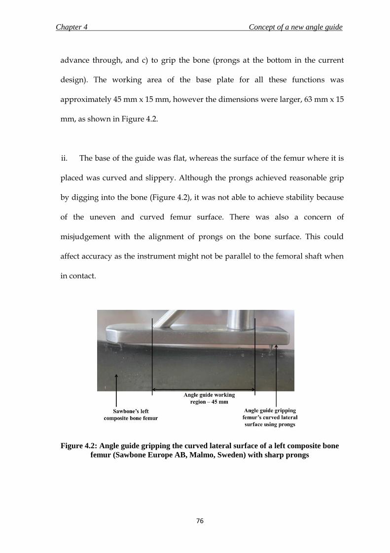
Chapter 4 Concept of a new angle guide
76
advance through, and c) to grip the bone (prongs at the bottom in the current
design). The working area of the base plate for all these functions was
approximately 45 mm x 15 mm, however the dimensions were larger, 63 mm x 15
mm, as shown in Figure 4.2.
ii. The base of the guide was flat, whereas the surface of the femur where it is
placed was curved and slippery. Although the prongs achieved reasonable grip
by digging into the bone (Figure 4.2), it was not able to achieve stability because
of the uneven and curved femur surface. There was also a concern of
misjudgement with the alignment of prongs on the bone surface. This could
affect accuracy as the instrument might not be parallel to the femoral shaft when
in contact.
Figure 4.2: Angle guide gripping the curved lateral surface of a left composite bone
femur (Sawbone Europe AB, Malmo, Sweden) with sharp prongs

Chapter 4 Concept of a new angle guide
77
iii. The guide was connected to the T-handle using a locking mechanism. Even
following locking, the handle moved relative to the guide, which might affect the
surgeon’s judgement of correct placement on the bone. The handle itself was too
small to hold in the hand, and was taken up for redesign (Chapter 7).
iv. The guide was unable to provide any level of intimation to the surgeon on
correct placement on the bone without the aid of fluoroscopy. This would be a
drawback especially during a MIS, as direct visual assistance will be limited.
v. The prongs achieved grip by digging in and scratching the bone. This may
be harmful to the bone especially in patients with weak bones, where the prongs
could cause considerable damage. The sharp prongs may also pose as a hazard to
the surgical staff as they might cause tearing of surgical gloves or injury to the
staff due to contact.
The design analysis of the generic angle guide was compared to the PDS
developed in section 3.9.3.1, and the resulting successes and failures of the
design’s conformity to the PDS are tabulated in Table 4.1.
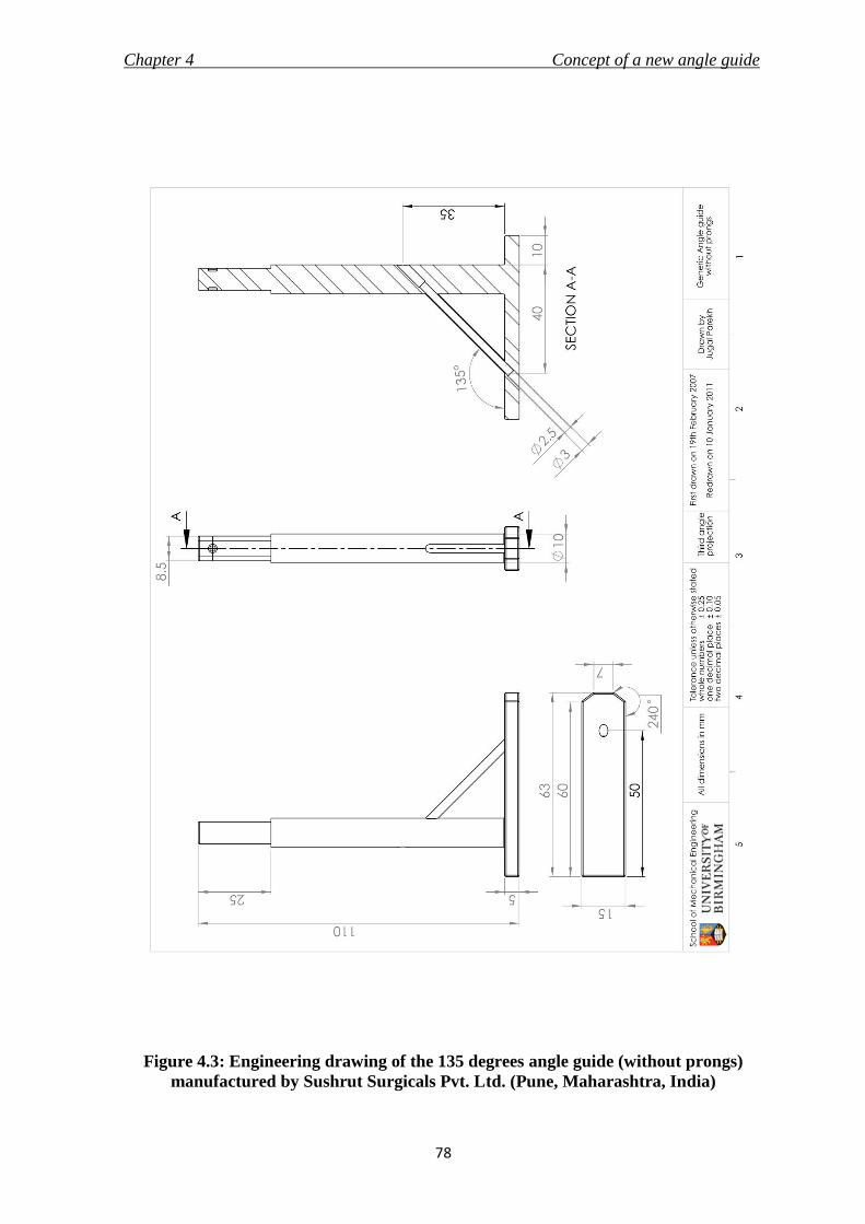
Chapter 4 Concept of a new angle guide
78
Figure 4.3: Engineering drawing of the 135 degrees angle guide (without prongs)
manufactured by Sushrut Surgicals Pvt. Ltd. (Pune, Maharashtra, India)
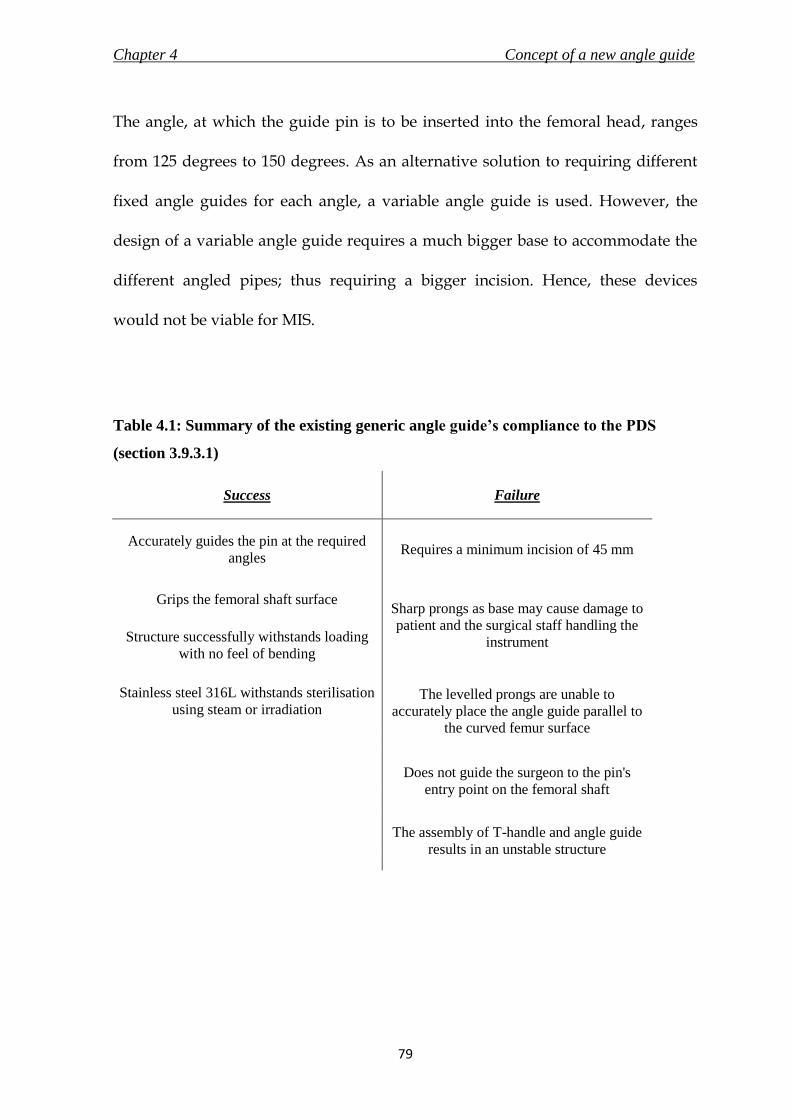
Chapter 4 Concept of a new angle guide
79
The angle, at which the guide pin is to be inserted into the femoral head, ranges
from 125 degrees to 150 degrees. As an alternative solution to requiring different
fixed angle guides for each angle, a variable angle guide is used. However, the
design of a variable angle guide requires a much bigger base to accommodate the
different angled pipes; thus requiring a bigger incision. Hence, these devices
would not be viable for MIS.
Table 4.1: Summary of the existing generic angle guide’s compliance to the PDS
(section 3.9.3.1)
Success Failure
Accurately guides the pin at the required
angles Requires a minimum incision of 45 mm
Grips the femoral shaft surface Sharp prongs as base may cause damage to
patient and the surgical staff handling the
instrument Structure successfully withstands loading
with no feel of bending
Stainless steel 316L withstands sterilisation
using steam or irradiation The levelled prongs are unable to
accurately place the angle guide parallel to
the curved femur surface
Does not guide the surgeon to the pin's
entry point on the femoral shaft
The assembly of T-handle and angle guide
results in an unstable structure

Chapter 4 Concept of a new angle guide
80
4. 4. Design objectives of a new angle guide
The assessment of the existing angle guide summarised in Table 4.1 identified the
short-comings of the current design. The goals of the process, listed below, would
attempt to eliminate these weaknesses and design a comprehensive new angle
guide for minimally invasive surgery.
i. The device should be able to accurately target and advance the guide pin at
the anatomically appropriate angle into the femoral head.
ii. It should be possible to insert and utilise the angle guide within an incision
length of 30 mm.
iii. An alternative base should be designed to replace the existing prongs to
grip the bone and guide the surgeon to the pin entrance point on the
femoral surface.
4. 5. Design requirements of a new angle guide
4. 5. 1. Overview
This section discusses the general requirements of the new angle guide and
justifies the specifications listed in the PDS in section 3.9.3.1. The points discussed
in this section are in accordance with the standard BS EN 12011 (1998), which

Chapter 4 Concept of a new angle guide
81
states the general requirements for instruments used in association with non-
active surgical implants. The standard was subsequently replaced by BS EN 16061
(2008) on 31st May 2009; and eventually by BS EN 16061 (2009) on 31st December
2009.
4. 5. 2. Function
The intended function of an angle guide is to be temporarily placed on the lateral
surface of the proximal femur to accurately provide both horizontal and vertical
reference required by the surgeon to insert a guide pin of a maximum diameter of
2.5 mm into the femoral head. This would aid in the correct placement of the lag
screw of the DHS implant and prevent complications during fracture treatment.
Owing to the differing femoral anatomy in patients, the angle of insertion of the
guide pin could range from 120 degrees to 150 degrees (at increments of 5
degrees), and thus the angle guide should cater to the required angle of insertion.
To achieve accuracy during the targeting of the guide pin, the device needs to
provide a stable grip on a curved and slippery bone surface.
4. 5. 3. Forces
The device will have to withstand two sets of forces – both compressive whilst in
use. They are - i) the surgeon’s force to hold the device in place, and ii) the force
due to the weight of soft tissues and muscle acting on top of the angled device.

Chapter 4 Concept of a new angle guide
82
The forces acting on the generic angle guide are illustrated in Figure 4.4. The
determinations of values of the forces are discussed in detail below.
i. Surgeon’s arm push force: The surgeon will be applying force through the
handle onto the device to hold it in place on the femur surface while inserting the
guide pin. The average available arm force has been stated to be 26.5 N (Hill,
1998). The same was checked and verified by the author by pushing against a
weighing scale placed on a wall, and the result was 27 ± 4 N after 5 trials.
Additionally, the maximum force that a fifth percentile American male, which
includes ninety percent of the US male population, is able to transmit is 222 N
(Tilley, 2002). This force was assumed as the maximum compressive load that the
device will have to endure.
Figure 4.4: Forces acting on a generic angle guide whilst in use

Chapter 4 Concept of a new angle guide
83
ii. Weight of soft tissues and muscles – The weight of soft tissues and muscles
acting on the angle guide was estimated to be only 4 N, on the basis of the
calculations described below. The calculations assume that the thigh and femur
are perfect cylinders, where x is the length of base plate of the angle guide (0.063
m as shown in Figure 4.2), R is the radius of thigh (radius of 0.0985 m or less
includes ninety eight percent of the US male population – Tilley, 2002), and r is
the radius of femur (0.014 m is the average radius of the femoral shaft at the
concerned region – Stephenson and Seedhom, 1999). The formula to calculate the
volume, V, of soft tissues and muscles in a single thigh (volume of a cylinder)
within the region of the angle guide as shown in Figure 4.5 is given by:
V = πx(R2-r
2) (4.1)
The total volume of soft tissues and muscles in a single thigh was calculated to be
0.0015 m3. Assuming that the volume of soft tissues and muscles on top of the
angle guide is a quarter of the total (Figure 4.5), the value was calculated to be
0.00038 m3. The density of muscle is reported to be 1060 kg/ m3 (Urbanchek et al.,
2001). Therefore, the resulting mass of muscles and soft tissues on top of the
angle guide would equal 0.40 kg, or approximately 4 N.
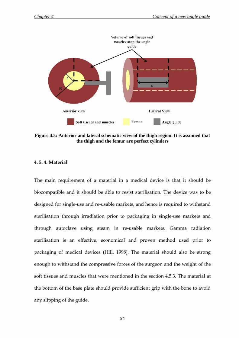
Chapter 4 Concept of a new angle guide
84
Figure 4.5: Anterior and lateral schematic view of the thigh region. It is assumed that
the thigh and the femur are perfect cylinders
4. 5. 4. Material
The main requirement of a material in a medical device is that it should be
biocompatible and it should be able to resist sterilisation. The device was to be
designed for single-use and re-usable markets, and hence is required to withstand
sterilisation through irradiation prior to packaging in single-use markets and
through autoclave using steam in re-usable markets. Gamma radiation
sterilisation is an effective, economical and proven method used prior to
packaging of medical devices (Hill, 1998). The material should also be strong
enough to withstand the compressive forces of the surgeon and the weight of the
soft tissues and muscles that were mentioned in the section 4.5.3. The material at
the bottom of the base plate should provide sufficient grip with the bone to avoid
any slipping of the guide.

Chapter 4 Concept of a new angle guide
85
4. 5. 5. Shape and Dimensions
The shape or dimensions of the angle guide should not require an incision length
of more than 30 mm. According to the design of the generic guide in use currently,
the distance from the front end of the pipe to the back end of the cylindrical bar
should not be more than 30 mm. The length of the perpendicular shaft connecting
the base to the handle should be long enough for the handle to stay out of the
patient’s body (outside of soft tissues, muscle and skin) when the base is in contact
with the femur. The measured length of the generic angle guide and T-handle
assembly manufactured by Sushrut Surgicals Pvt. Ltd. (Pune, Maharashtra, India;
angle guide shown in Figure 3.9) was 165 mm. The distance from the bottom of the
base plate to the centre of the guide pin inserting hole on the angle guide was 40
mm.
4. 5. 6. Ergonomics and design attributes
The guide was to be designed for use by surgeons of either handedness. It was
noted by Prof. N. Maffulli that the guide should feel sturdy and that the surgeon
should not experience a ‘feeling’ of bending during the use of the device,
especially when pushing the guide against the femur. The design of the new angle
guide was to be kept simple to avoid a steep learning curve for the surgeons.

Chapter 4 Concept of a new angle guide
86
4. 5. 7. Base plate and surface of femur
One of the important objectives of the design process was to replace the steel
prongs in the generic angle guide used to grip the bone surface. It was important
to understand the surface anatomy of the bone in the region that will interface
with the angle guide to understand the requirements of a design that would
conform to the bone surface.
The base of the angle guide would be in contact with a curved cortical bone, which
might be slippery due to the presence of blood. Using a standardised three
dimensional model of the femur on SolidWorks (Dassault Systèmes SolidWorks
Corp, Concord, Massachusetts, USA), and using values stated in past literature
work on the structure of the femur, it was possible to derive a range for the value
of the radius of curvature of that particular region of femur. Figure 4.6 shows a
three dimensional model of the third generation composite femur (#3306,
Sawbone Europe AB, Malmo, Sweden) created by Rob Day, Subajan Sivandran
and Shandip Abeywickrema; it is available on the Internet (http://bit.ly/gjpt4k)
through the BEL Repository managed by the Istituti Ortopedici Rizzoli, Bologna,
Italy. An angle guide was placed at the location where it is supposed to be during
the surgery, and using SolidWorks tools, the radius of curvature was measured to
be 17.59 mm. Stephenson and Seedhom (1999) have stated the cross-sectional area
of human femoral shafts (including medullary canal) to be in the range of 550 mm2
to 675 mm2. Assuming the shaft is cylindrical, the radii would hence range from

Chapter 4 Concept of a new angle guide
87
13.2 mm to 14.7 mm. After taking into consideration these two findings, the range
of radius of curvature for the lateral femoral surface was deduced to be between
13 mm and 18 mm. However, the cross-sectional area might differ with race and
sex. No further studies were found stating the cross-sectional area of femur at the
concerned region. Therefore, the value of radius of curvature selected for the
design specification of the new angle guide was higher at 20 mm to consider the
variability.
Figure 4.6: Three dimensional model of composite bone femur was used on
SolidWorks to calculate the radius of curvature of the lateral surface
4. 5. 8. Single-use or re-use market
The new angle guide, along with forming a part of the new implant’s instrument
set, was also designed to replace the existing angle guide from the generic DHS
instrument set in use presently to promote minimally invasive surgery and the
relating benefits. Considering the world-wide popularity of the existing DHS, it is

Chapter 4 Concept of a new angle guide
88
important for the design specifications of the new angle guide to comply with
requirements of both re-use and single-use markets. Apart from the material
specifications to allow sterilisation using both methods, as mentioned in section
4.5.4, it is also important to package the device differently in the two markets. It is
required by standard BS EN ISO 12011 (1998) to clearly mention on the packaging
whether the instrument would be re-usable. It will also be required to supply the
sterilisation and disposal instructions according to the different market. In case of
a re-usable instrument, it would be important for the manufacturer to specify the
maximum cycles of use that the instrument can endure before disposal. The new
angle guide should be able to perform the intended functions efficiently and safely
in either market.
It could be argued that substituting the material which can withstand both types
of sterilisation with a suitably cheaper one, which can withstand the sterilisation
as required by the type of market, may lower the cost of the manufactured
product. However, the economies of scale due to mass production of a single
design, the possibility of recycling the material from used instruments from both
markets, and the ability to supply according to demands from the markets would
be highly beneficial. Hence, a single design of the new angle guide was to be made
to comply with requirements of both markets. This would allow the product to be
supplied in either market with appropriate changes to be made only to the
packaging and information to be supplied by the manufacturer.

Chapter 4 Concept of a new angle guide
89
4. 6. Evolution of a concept
4. 6. 1. Overview
Various concept ideas were generated for the new angle guide based on the design
objectives and requirements discussed in the previous sections. The ideas are
discussed in detail in this section. The section concludes with the final concept that
was selected to be taken forward for detail design.
After consultation with Prof. N. Maffulli, it was decided to design the handle and
the angle guide as one structure. Elimination of the locking mechanism would
reduce the probability of manufacturing defects and an unstable jig. However, it
was also decided to inspect the handle individually at a later stage of the research
(Chapter 7). Hence, the ideas and the final concept of a new angle guide were
connected to a cylindrical handle with a diameter of 30 mm. Also for the
convenience of the design process, angle of 135 degrees was considered for all
specifications and discussions as the fractured femur’s neck/shaft angle. The final
design specification of the new angle guide (section 6.3.1) discusses the
possibilities of the other angles.
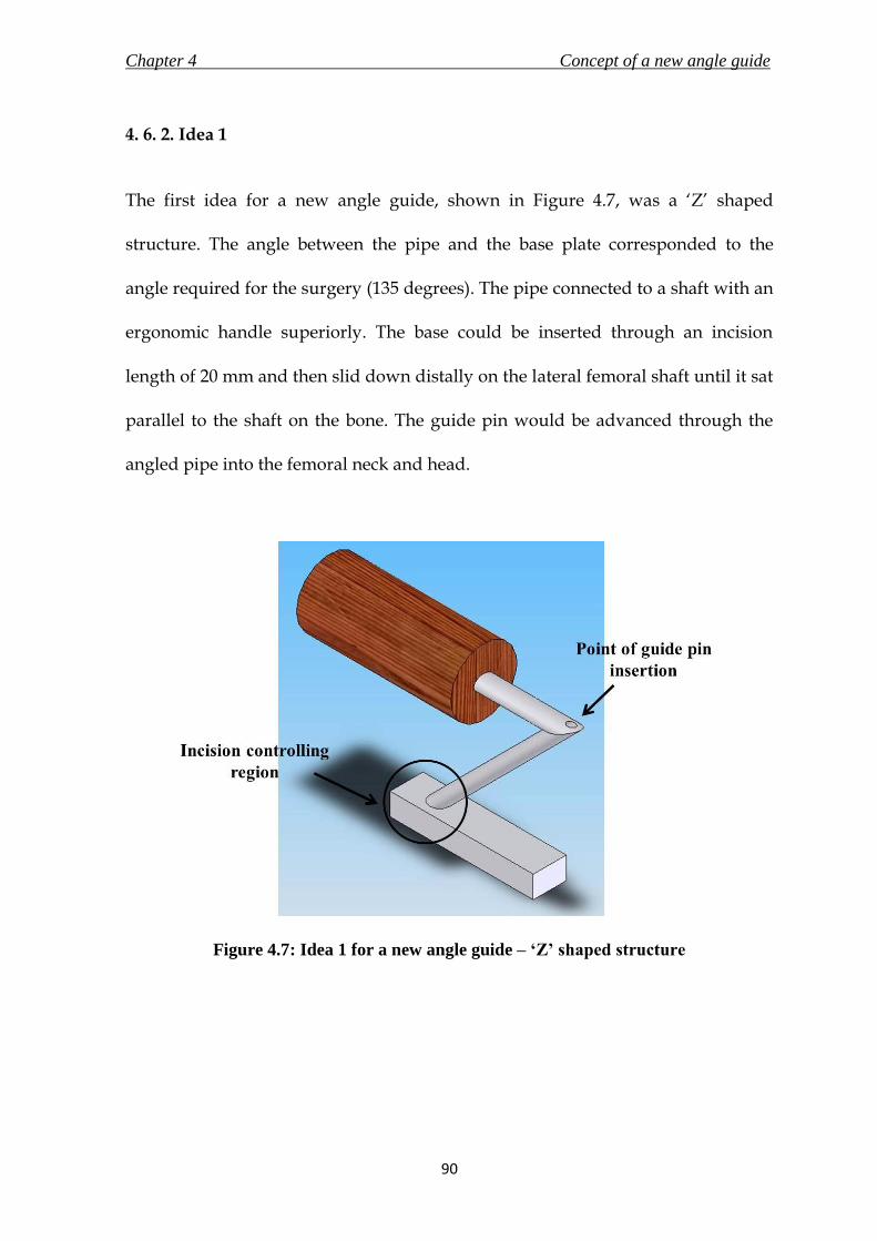
Chapter 4 Concept of a new angle guide
90
4. 6. 2. Idea 1
The first idea for a new angle guide, shown in Figure 4.7, was a ‘Z’ shaped
structure. The angle between the pipe and the base plate corresponded to the
angle required for the surgery (135 degrees). The pipe connected to a shaft with an
ergonomic handle superiorly. The base could be inserted through an incision
length of 20 mm and then slid down distally on the lateral femoral shaft until it sat
parallel to the shaft on the bone. The guide pin would be advanced through the
angled pipe into the femoral neck and head.
Figure 4.7: Idea 1 for a new angle guide – ‘Z’ shaped structure

Chapter 4 Concept of a new angle guide
91
4. 6. 3. Idea 2
Idea 2 consisted of an angled pipe connected to a base plate. The exterior of the
angled pipe was moulded to resemble a handle for holding the device, as shown
in Figure 4.8. The objective of this concept was to design a simple device to satisfy
the function of an angle guide. An incision of only 25 mm would allow the
insertion of the device, as the diameter of the shaft was the largest of the
dimensions that controlled the length of incision required for this design.
Figure 4.8: Idea 2 for a new angle guide

Chapter 4 Concept of a new angle guide
92
The idea applied two new innovations to the base plate which would assist the
device to attain - i) the stability and avoid slippage on the bone; and ii) provide
feedback to the surgeon when it is in position on the femur for insertion of the
guide pin. The innovations are shown in Figure 4.9, and are described in detail
below.
i. Stability and Grip: The bottom of the base plate was curved to complement
a curved femur. The radius of curvature of the femur was found to be in the range
of 13 mm to 18 mm. However, to accommodate any irregularities in the radius of
curvature of the femur, the radius of curvature of the base plate was determined to
be 20 mm. The curvature on the base plate would restrict lateral motion of the
device once it is placed on the bone.
The grip of the device on the bone would be enhanced by eliminating the sharp
prongs from the design by attaching a layer of either silicone elastomer or using
stainless steel with a rough texture, or a combination of both. This proposition is
discussed in more detail in Chapter 5, which describes a test conducted to find the
values of the static coefficient of friction of the different materials. The results
assisted in finalising the material that would provide the best grip on a slippery
bone surface.

Chapter 4 Concept of a new angle guide
93
Figure 4.9: Innovations applied to the base of the new angle guide
ii. Feedback: The guide pin entry point for a 135 degrees femoral neck is
approximately 20 mm below the vastus lateralis ridge as discussed in the surgical
technique in section 3.6.3. The distance from the hole for the guide pin exit at the
bottom of the base plate to the front end of the base plate in Idea 2 was 20 mm.
The surgeon would hence be able to estimate the correct placement of the angle
guide on the femur, which later may be confirmed with fluoroscopy images. This
may reduce the time and effort required to correctly place the angle guide.
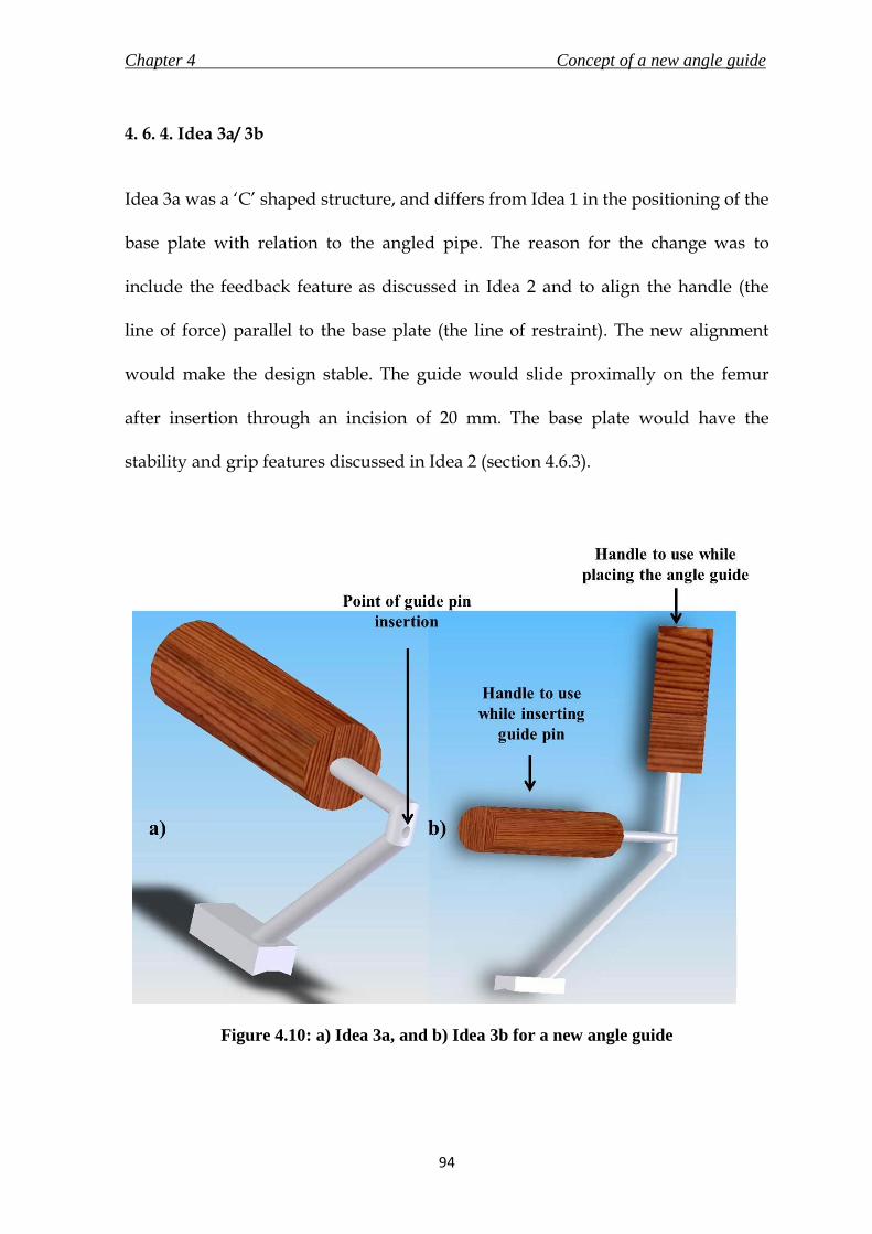
Chapter 4 Concept of a new angle guide
94
4. 6. 4. Idea 3a/ 3b
Idea 3a was a ‘C’ shaped structure, and differs from Idea 1 in the positioning of the
base plate with relation to the angled pipe. The reason for the change was to
include the feedback feature as discussed in Idea 2 and to align the handle (the
line of force) parallel to the base plate (the line of restraint). The new alignment
would make the design stable. The guide would slide proximally on the femur
after insertion through an incision of 20 mm. The base plate would have the
stability and grip features discussed in Idea 2 (section 4.6.3).
Figure 4.10: a) Idea 3a, and b) Idea 3b for a new angle guide

Chapter 4 Concept of a new angle guide
95
Idea 3b added a vertical handle to Idea 3a. The vertical handle would make it
easier for the surgeon to insert the guide through the smaller incision, and holding
the horizontal handle would keep the guide stable while inserting the guide pin.
Idea 3a and 3b are shown in Figure 4.10a and 4.10b.
4. 6. 5. Idea 4
Idea 4 was a union of the existing market design of the angle guide to the
requirements stated earlier to reduce the surgical incision length to less than 30
mm. The cylindrical support shaft of the generic design was connected to the base
plate at an angle of 120 degrees for a 135 degrees angle guide, as shown in Figure
4.11. This reduced the distance between the support shaft and the pipe for the
guide wire from 45 mm to 23 mm, and hence the incision required to insert the
guide was reduced. The stability and grip, and the feedback features were the
same as in Idea 2. The concept also included a T-handle instead of a normal
cylindrical handle. The T-handle is used in the existing set of generic DHS
instruments.
4. 6. 6. Concept Evaluation
The ideas underwent a thorough inspection by a team of engineers – Prof. D. W. L.
Hukins, Dr. D. E. T. Shepherd, the author and by a consultant surgeon – Prof. N.
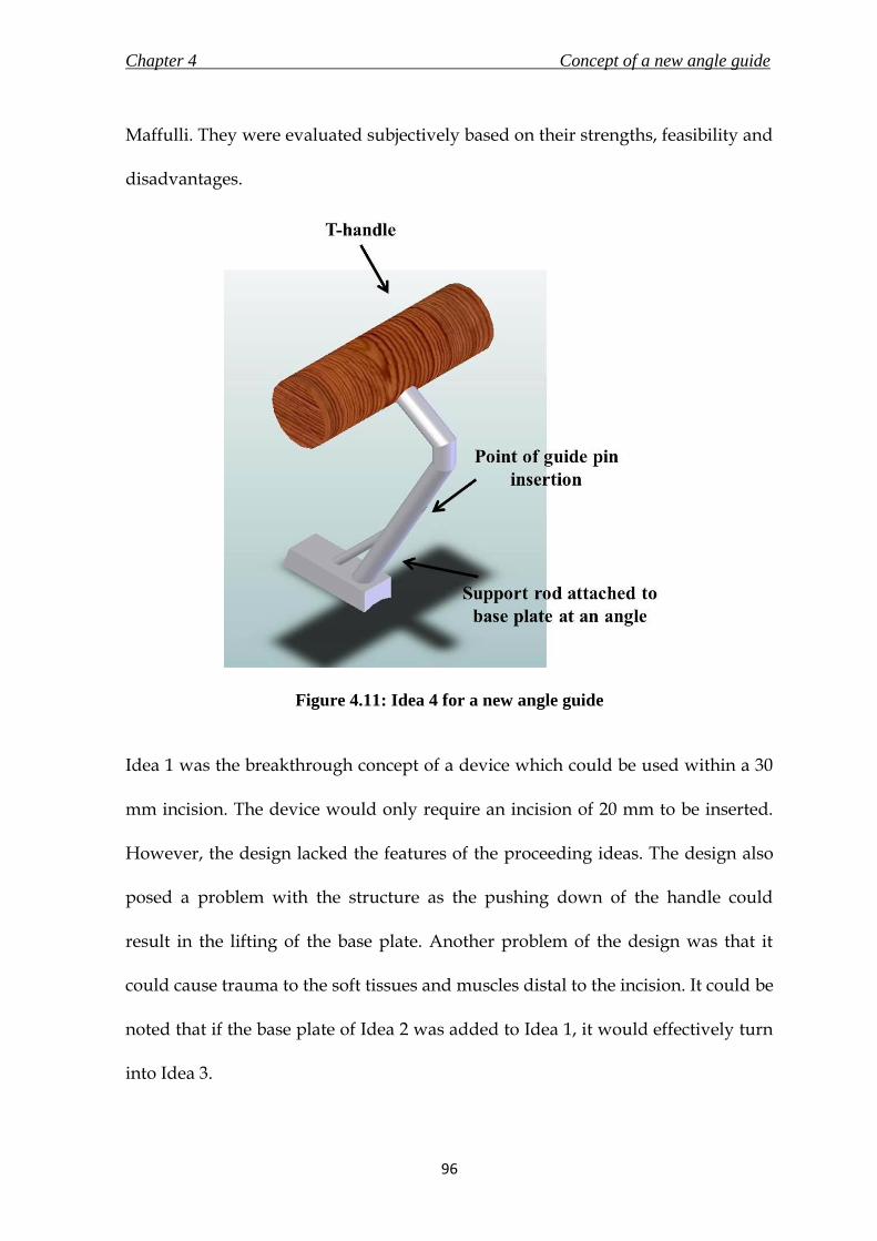
Chapter 4 Concept of a new angle guide
96
Maffulli. They were evaluated subjectively based on their strengths, feasibility and
disadvantages.
Figure 4.11: Idea 4 for a new angle guide
Idea 1 was the breakthrough concept of a device which could be used within a 30
mm incision. The device would only require an incision of 20 mm to be inserted.
However, the design lacked the features of the proceeding ideas. The design also
posed a problem with the structure as the pushing down of the handle could
result in the lifting of the base plate. Another problem of the design was that it
could cause trauma to the soft tissues and muscles distal to the incision. It could be
noted that if the base plate of Idea 2 was added to Idea 1, it would effectively turn
into Idea 3.

Chapter 4 Concept of a new angle guide
97
Idea 2 gave a simple solution to the design objectives. The idea was accompanied
by two novel approaches to address the issues of gripping and feedback to the
surgeon. However, the solution was not feasible from an engineer’s point of view
as excessive or accidental application of force by the surgeon could result in the
guide slipping forward, which could cause injury to the patient and the user. From
the surgeon’s perspective, the design lacked the character of being a surgeon’s
instrument. This was an important point considering the new angle guide was
attempting to replace an instrument that has been in use for over two decades.
Idea 3a was a stable design which included all the features and objectives that
were required of a new concept. Idea 3b was a practical solution but it got too
bulky for the intended function, and thus Idea 3b was eliminated from being
selected as the final concept.
Idea 4 was able to achieve all the objectives in a design which was very similar to
the existing generic design of an angle guide. Idea 3a and 4 did not pose any
problems from an engineer’s perspective. However, Idea 4 was preferred not only
due to the familiarity that would add to the confidence of surgeons whilst using
the new instrument, but also due to the existence of a T-handle, which was
described by the surgeon as more comfortable to use than a normal cylindrical
handle.

Chapter 4 Concept of a new angle guide
98
4. 6. 7. Concept of a new angle guide
The objective of a new angle guide design was to utilise it through an incision less
than 30 mm. The new concept should not compromise on its primary function of
accurately inserting a guide pin into the femoral head. It should also provide a
good stable grip on the bone and intimate the surgeon on correct placement to
insert the guide pin.
Idea 4 was selected as the final concept for a new angle guide and is simulated in
use in Figure 4.12a. The new concept was able to combine the familiarity of the
existing angle guide design with the objectives of this design process. A prototype
of the concept was manufactured for visual evaluation and is shown in Figure
4.12b. The prototype was manufactured at the automotive workshop at the School
of Mechanical Engineering in the University of Birmingham using materials
available from within the workshop. The device was manufactured by the author
and Mr. Lee Gauntlett from the automotive workshop. The angle guide was made
using mild steel, and the handle was made of beech wood. Following the concept
evaluation, it was decided to bring the position of the handle in line with the front
end of the base plate to add more stability to the design.

Chapter 4 Concept of a new angle guide
99
Figure 4.12: a) Final concept of the new angle guide shown with a guide pin passing
through it, and b) A manufactured prototype of the final concept
The concept was taken forward through a detail design process and verification,
discussed in Chapter 6. Prior to that, a new base material was selected (Chapter 5)
for the new angle guide to provide grip on slippery bone surfaces.
A survey was conducted by the author and Dr. D.E.T. Shepherd, and organised by
Prof. N. Maffulli on 7th December 2007 at the City General Hospital (Stoke-on-
Trent, UK). The purpose of the survey was to determine an appropriate material
(silicone elastomer or stainless steel) that would be most comfortable to use for the
interface of the instrument’s base with the bone. The details of the survey are
described in Appendix A. Although the survey was not conclusive, as mentioned
in section A.5, the author was able to get the surgeon’s perspective on handling of
a bone-interfacing instrument. A useful observation was that eight out of ten
surgeons faced difficulty in placing an instrument on to the bone surface; seven

Chapter 4 Concept of a new angle guide
100
reasoned that slippage of the instrument was the factor; stability of the instrument
was a factor for two respondents; poor design, insufficient access to bone site and
learning curve were considered to be factors by one respondent (each respondent
gave more than one factor). Two surgeons also suggested that better grip and
curved base would enhance the bone-instrument interface. Due to the inconclusive
results and the small sample size, the findings were not considered in the design
process of the new angle guide.
4. 7. Summary
The summarising points of the chapter are listed below.
i. A new angle guide, which would be capable of being inserted through a
maximum incision length of 30 mm for use during minimally invasive
surgery, was taken up for design.
ii. A PDS for the new angle guide was prepared in accordance with clauses
stated in standard BS EN 12011 (1998), which states the general requirements
for instrumentations for use in association with non-active surgical implants.
iii. A total of five concepts, based on the requirements laid in the PDS, were
discussed in this chapter. Idea 4, a design similar to the generic DHS angle
guide was selected to be taken through to the detail design stage.

Chapter 5 A new base material for the new angle guide
101
A NEW BASE MATERIAL FOR
THE NEW ANGLE GUIDE
5. 1. Chapter at a glance
5. 1. 1. Chapter overview Figure 5.1 shows the chapter overview in the form of a flowchart.
Figure 5.1: Flowchart of the chapter structure
5. 1. 2. Keywords Bone – instrument interface material; silicone elastomer; static coefficient of friction; synthetic blood solution; textured stainless steel
Replace spikes on base to grip femur surface
Select compliant materials
Verify superior grip by measuring static coefficient
of friction in presence of synthetic blood solution
Results and statistical analysis
New base material for angle guide

Chapter 5 A new base material for the new angle guide
102
5. 2. Introduction
It was decided in section 4.4 that the new design of the angle guide would not
have spikes as a feature to grip the bone. The spikes are unstable as they do not
follow the curvature of the bone and could also cause trauma during use. These
problems might be overcome by having a roughened steel surface. The only
publication discovered by the author on the frictional forces between distinctive
metal surfaces and polyurethane or bone was by Dammak et al. (1997). They
concluded that a surface with a cast meshed texture provided the highest friction
coefficient on the bone. In this work the surfaces were specially designed and
manufactured to be considered for joint arthroplasty implants intended for long
term fixation. On the contrary, the angle guide would be used for a much shorter
period and the purpose of the instrument would not justify the manufacturing
costs of a meshed surface. Furthermore, the surfaces used during the tests by
Dammak et al. (1997) were dry. However, in practice, the interface between
instrument and the bone surface would be covered by blood, leading to a reduced
coefficient of friction.
An alternate approach to the use of stainless steel was to use a compliant material
that conforms to the bone surface without plastic deformation when the surgeon
pushes down on the instrument. Silicone elastomers were chosen as examples of
compliant, biocompatible materials (Colas and Curtis, 2004) in this study. The
elasticity of a silicone insert would also be beneficial as it would conform to the

Chapter 5 A new base material for the new angle guide
103
bone surface on application of force. Furthermore, this material is also able to
withstand sterilisation with irradiation and steam, which was considered as an
important specification for the new angle guide (section 4.5.4)
5. 3. Investigation objective
The purpose of this study was to determine whether textured stainless steel
manufactured with conventional metal finishing processes or silicone elastomer
would provide superior grip on the bone. Standard textured stainless steel
surfaces were used that had been roughened by surface grinding, sand blasting
and spark erosion. Three different grades of silicone elastomers were used that
were intended for fabrication of medical devices.
The superior grip was evaluated by measuring the coefficient of static friction, µ,
at the bone - material interfaces in the presence of a synthetic solution that had a
comparable viscosity to blood. The determination of the coefficients would aid in
selecting the material to provide grip and stability to the angle guide on a slippery
bone.

Chapter 5 A new base material for the new angle guide
104
5. 4. Materials and Methods
5. 4. 1. Variables affecting the measurement of coefficient of friction
The various factors that would influence the value of coefficient of static friction
measured in a system are – a) interfacing materials and their surface texture
(Surface roughness and method of surface preparation), b) normal force, c)
lubricant, d) displacement and velocity, and e) environmental factors -
temperature and humidity (ASTM G115, 2004).
This experiment measured the coefficient of static friction by changing the
interfacing materials, the surface textures of the materials and the normal axial
force acting on the interface. The purpose of this experiment was to determine a
material that would provide better grip on bone in vivo. There was no rationality
in measuring the coefficient of static friction due to variability in the other factors
since the lubricant (blood) and environmental factor would remain the same in
actual conditions. The angle guide is supposed to grip the bone and not shift from
its position. Hence, the effect of displacement and velocity on the coefficient
would also not affect the selection of material.
In this experiment, bone would be coupled with six different kinds of materials
(three types of stainless steel surfaces and three types of silicone elastomers). It
was necessary that the bone samples had flat external surfaces for a steady slide of

Chapter 5 A new base material for the new angle guide
105
the coupling material. Although it would be beneficial for the final test results to
have high number of bone samples, it was difficult to find and extract them with
flat external surfaces. However, a minimum of three samples were procured, and
were put through five test runs with each of the coupling material to ensure valid
statistical comparison.
The surface roughness of the materials used in this experiment were characterised
using Ra (centre line average). Other descriptors of surface roughness include Rt
(distance between highest peak and the lowest valley), Rp (distance between
highest peak and the mean line), Ry (distance between mean line and lowest
valley), and Rz (distance between the averages of five highest peaks and five
lowest valleys) (Bhushan, 2001). The average value denoted by Ra was selected
over the extreme values of the other descriptors to minimise the error caused due
to an unrepresented peak or valley. The purpose of measuring the surface
roughness in this experiment is to reproduce it during manufacturing of the new
angle guide using conventional methods, which would be possible with an
average roughness value. Manufacturing of a surface profile with accurate surface
roughness measurements denoted by the extreme descriptors would result in an
expensive process, usually applied for highly-polished items.
Low friction can be achieved with presence of a layer of lubrication between the
coupling materials. The ability of the fluid to lubricate will depend on the ease
with which it will flow into the bearing surface to form a lubricating film, which is

Chapter 5 A new base material for the new angle guide
106
influenced by the viscosity of the fluid. The presence of blood as a lubricant in
between the stationary instrument and the bone in vivo would reduce the
coefficient of static friction at the interface. On the contrary, lubricity is defined as
the ability of a lubricant to reduce wear and friction, other than by its purely
viscous properties (Hamrock et. al., 2004; Bhushan, 2001). The lubricity of the
lubricant would have been useful in a study to measure friction at the ball-socket
joint in total hip replacement implants, where multiple cycles of loading are
expected, and a lubricant with good lubricity would elongate the life of the
implant. Therefore, a blood analogue solution that has comparable viscosity to
blood to act as a lubricant between the coupling materials will be selected for this
experiment.
5. 4. 2. Bone specimen
Three cortical specimens (approximate dimensions of 25 mm × 15 mm × 5 mm)
were cut from the flattest region of the femoral shaft of a frozen bovine femur
obtained from Fresh Tissue Supplies (East Sussex, UK). The flattest region was
discovered at the lateral-proximal end of the bone. The bone was initially cut in a
safety cabinet, with a saw to achieve a roughly rectangular-shaped block.
Subsequently a file was used on the inner sides of the cortical bone to file it down
to the desired dimensions. The outer surface of the bone was not cut or filed. The
soft tissues were removed with a surgical scalpel. The specimen was then rinsed
with distilled water to clean the blood and remaining soft tissues off the surface of

Chapter 5 A new base material for the new angle guide
107
the bone. The bone was then dried with a lint-free wipe. Each sample was secured
in an open steel box (internal dimensions being 31 mm × 26 mm × 5 mm) using
acrylic cement (WHW Plastics, Hull, UK). The bone surface was levelled using a
spirit level and protruded above the top of the box by about 3 mm as shown in
Figure 5.2. The three samples were stored in a vacuum-sealed plastic bag,
wrapped in tissue soaked in Ringer’s solution, in the freezer at -40°C, when not in
use. The samples were defrosted for 12 hours, rinsed with distilled water and
dried with a lint-free wipe prior to the experiment.
Figure 5.2: Bone specimen (average dimension of 25.3 mm × 15.4 mm) secured in an
open steel box with acrylic cement
5. 4. 3. Stainless steel samples
Standard samples of finishes on stainless steel surfaces obtained by surface
grinding (SG), sand blasting (SB) and spark erosion (SE) (surface dimension being

Chapter 5 A new base material for the new angle guide
108
30 mm × 30 mm, manufactured by Rubert & Co. Ltd. Cheadle, Cheshire, England)
were used. The three surfaces are shown in Figure 5.3. Surface roughness (Ra)
values were measured using a contact method (Form Talysurf-120L, Taylor-
Hobson Ltd., Leicester, UK) using a diamond tipped stylus (radius 2 µm) over a
surface area of 1 mm2. The machine was calibrated to 0.1443 µm. The readings
were taken 6 times on different regions of the samples’ surface and the values are
tabulated in Table 5.1.
Figure 5.3: Surface finishes providing roughened texture on stainless steel samples
5. 4. 4. Silicone elastomer samples
Three different grades of silicone were used: Silastic Q7-4720, Silastic Q7-4750 and
Silastic Q7-4780 (all from Dow Corning Ltd, Coventry, UK). All three were
biomedical grades intended for fabricating medical devices, including those
intended for implantation in humans for less than 30 days (as per manufacturer’s
data sheet). The angle guide in contrast would not be in use for more than a few

Chapter 5 A new base material for the new angle guide
109
minutes and therefore these materials were considered suitable as a candidate
material.
According to the supplier’s data sheet, the softest silicone was Q7-4720 (Shore A
hardness 23) followed by Q7-4750 (Shore A hardness 50) and Q7-4780 (Shore A
hardness 77). The materials were supplied in two parts that were mixed in a
Schwabenthan Berlin two-roll mill (Engelmann & Buckham Ltd, Alton, UK).
Sheets of silicone (2 mm thick) were prepared in a Moor E1127 hot press (George E
Moore & Sons Ltd, Birmingham, UK) under a 50 kN load (applied to an area of
175 mm × 150 mm ) at a temperature of 116°C for 12 minutes, as recommended by
the supplier. Circular samples of 70 mm diameter were cut from these sheets using
a template. Surface roughness values were measured for each grade of silicone
sheet as described for stainless steel in section 4. 4. 2., and are shown in Table 4.1.
5. 4. 5. Blood analogue solution
The synthetic blood solution (1000 g) was made by dissolving xanthan gum (0.4 g;
CAS – 11138-66-2, Sigma Aldrich, Town, Dorset, UK) and sodium chloride (5 g;
table salt, J Sainsbury, London, UK) in glycerol (400 g; Fisher Scientific,
Loughborough, Leicestershire, UK) and distilled water (594.6 g) (Brookshier and
Tarbell, 1993). The solution has been used in various studies, including in a test by
Banerjee et al. (2008) in their study to assess the severity of epicardial coronary
stenosis and by Pohl et. al. (1996) for in vitro testing of artificial heart valves.

Chapter 5 A new base material for the new angle guide
110
5. 4. 6. Measurement of coefficient of friction
ASTM G115 (2004) was used as a guide for the setup and execution of this
experiment. The setup of the experiment is shown in Figure 5.4. The force to
overcome the friction between the bone and the silicone or textured steel was
provided by a Bose ELF 3200 materials testing machine, operated under the
control of WinTest software (Bose Corporation, ElectroForce Systems Group,
Minnesota, USA). The machine was equipped with a load cell of full scale of 225 N
and a displacement transducer with a full scale of 13 mm. The force required to
overcome friction and move the box containing the bone (Figure 5.5) was applied
by a nylon monofilament fishing line (Sunset line and twine, Kansas, USA;
diameter 0.50 mm and capacity of 13.6 kg). As the purpose of the study was to
calculate the coefficient of static friction, an elastic force measuring system was
very important (ASTM G115, 2004). Due to its compliance, a nylon monofilament
line had substantial elastic strain prior to initiation of motion of the box. This
allowed the force measuring transducer to record the gradual accumulation of the
force, and finally the “breakaway force” at which the box was able to overcome
static friction and commence sliding. The breakaway force was used to calculate
the coefficient of static friction.
The line to the testing machine from the box was passed under a pulley. The
pulley was made of nylon (60 mm diameter, thickness of 9 mm, 0.50 mm wide and
0.25 mm deep groove for nylon line) with a single row radial ball bearing (inner

Chapter 5 A new base material for the new angle guide
111
diameter 10 mm, outer race diameter 26 mm, sourced from RS Stock # 286-7568,
RS Components Ltd., Northamptonshire, UK) in the centre to facilitate negligible
friction. Nylon was chosen as the material for fabrication as it provided negligible
friction with the nylon monofilament line (nylon-on-nylon static coefficient of
friction is 0.15 to 0.25, Avallone et al., 2007), was readily available at the time of
testing and because of its ease of processing.
From the other side of the bone box, the line passed over a second pulley and was
tied to a counter weight of 7.03 N (a weight block of 5.01 N on a 2.02 N holder).
The reason for the counter weight were two-fold – a) the downward force due to
the counterweight would balance the upward force from the first pulley towards
the machine; and b) to stabilise the box containing the bone and weight assembly
by providing tension through the fishing line. To attain a flat piece of bone, the
size of the sample had to be very small. Thus, the assembly of the bone with the
box and weight on top would not be steady due to the shape of the structure and
would be unstable during sliding causing errors in force measurements. The
height of the bench on which the material-bone assembly rested was adjusted to
ensure that the nylon filament lines were straight between the set of pulleys.
The resistance provided by the pulleys was negligible when compared to the force
measured. To verify the presence of negligible resistance, a weight was hung off
the monofilament line over the pulleys and the force measured by the transducer
was recorded. For a weight of 20.05 N (measured using an Ohaus GA200D

Chapter 5 A new base material for the new angle guide
112
balance, Ohaus, New Jersey, US) that hung off the line, the transducer recorded a
value of 20.01 N; 5.00 N for a weight of 5.01 N.
Figure 5.4: Test rig setup on ELF 3200 testing machine to measure the static
coefficient of friction
Two test runs with dry steel on steel interface were conducted on the test
apparatus to measure their static coefficient of friction. The literature value for
grease-free steel on steel interface is 0.78 (Avallone et al., 2007). The test runs
yielded coefficient values of 0.60 (normal force of 2.36 N; force required to initiate
slide was 1.41 N) and 0.66 (normal force of 2.97; force required to initiate slide was
1.96 N). Although the test results were not the same as the literature value, the aim
of the experiment was to compare the different material combinations, and not

Chapter 5 A new base material for the new angle guide
113
provide bench-mark values for the different interfaces. It should also be noted that
the coefficient values would also depend on the surface roughness and other
factors discussed in section 5.4.1.
Figure 5.5: Exploded view of bone-material assembly setup on the testing rig
Figure 5.5 shows how the samples and equipment were assembled onto a custom
made testing rig to measure the coefficient of static friction. The cup holding the
bone specimen (Figure 5.2) was screwed to a mass at the top (gross mass of
assembly was 0.47 kg and masses were added in the range of 0.1 kg to 0.4 kg). This
assembly was placed on top of the material (stainless steel or silicone elastomer)
sample. Silicone elastomer was screwed on top of a height-adjustable specimen
bench, whereas stainless steel samples were attached to the bench using double-
Chapter 5 A new base material for the new angle guide
114
sided adhesive-tape. The samples were verified for absence of any undesirable
movement due to application of shear force by pushing against them. The mass on
top of the bone sample created a compressive force at the interface between the
bone and the material.
Before measuring the coefficient of friction, the bone surface was coated with the
blood analogue solution, described in section 5.4.4, to mimic the lubrication of
blood. A pipette was used to pour 5 mL of the solution on the surfaces of the
material and the bone; a paintbrush (diameter 10 mm) was then used to evenly
distribute the analogue. Measurements were made at room temperature (20°C).
The testing machine was operated in displacement control (0.1 mm/s for a total
displacement of 7 mm) and the force was recorded (200 data points per second).
The procedure measured the horizontal load-displacement response of the
interface in the presence of a constant normal force. Five measurements were
made between each pair of surfaces; each pair was loaded with five different
weights. CAD drawings of the testing rig and the pulley can be found in Figures
5.6 to 5.8.
5. 4. 7. Data analysis
A plot of recorded force to slide the bone against displacement was generated for
each test run. The graphs were plotted using SigmaPlot 11 (Systat Software Inc.,
Chicago, Illinois, USA). The breakaway force, F’, defined as the force required for

Chapter 5 A new base material for the new angle guide
115
overcoming static friction and initiating slide, was considered to be the first
maximum force in the plot. The breakaway force could be lower, higher, or even
equal to the force needed to maintain the surface sliding in the subsequent relative
motion (Bhushan, 2001). If static friction is much larger than kinetic friction, it is
possible for a system to exhibit stick-slip (ASTM G 115, 2004). The interface was
considered to be stick-slip when the bone block assembly would repeatedly stick
to the interfacing material, followed by a slide of certain distance (slip) due to
accumulation of a certain force. During such an occurrence, F’, was determined as
the highest force recorded before the bone slipped on the material. F’ was then
plotted against the respective compressive load and a regression line was fitted to
the data for every bone-material pair. The value of the slope of the regression line
was the coefficient of static friction, µ, for that particular interface.
5. 4. 8. Statistics analysis
Statistical calculations were performed using MINITAB Release 16 Statistical
Software (Minitab Inc., Pennsylvania, USA). Normality of the distributions was
assessed using the Anderson–Darling test (Bland, 2000). Data was compared using
the one-way ANOVA for the normally distributed data with the significance level
set at 0.05 for all tests.

Chapter 5 A new base material for the new angle guide
116
Figure 5.6: Engineering drawing of the custom made test rig base used to measure the
static coefficient of friction

Chapter 5 A new base material for the new angle guide
117
Figure 5.7: Engineering drawing of the height-adjustable specimen bench, which was
screwed on to the testing rig

Chapter 5 A new base material for the new angle guide
118
Figure 5.8: Engineering drawing of the nylon pulley manufactured for use on the
testing rig. The pulley was fixed with a sourced ball bearing in the centre.

Chapter 5 A new base material for the new angle guide
119
5. 5. Results
Table 5.1 gives the surface roughness of the bone, silicone elastomers and steel
surfaces used in these experiments.
Table 5.1: Mean surface roughness (mm) measured using a contact method along
with their standard deviations
Material Surface Roughness (Ra - µm)
Silastic Q7 - 4720 1.08 ± 0.30
Silastic Q7 - 4750 1.45 ± 0.08
Silastic Q7 - 4780 1.73 ± 0.28
Surface Grind 0.13 ± 0.04
Sand Blast 2.19 ± 0.14
Spark Erode 8.94 ± 1.56
A typical plot of force against displacement for a silicone surface in contact with
bone is given in Figure 5.9. The interface did not exhibit a high breakaway force
compared to the force required to sustain slide. Figure 5.10 shows a typical plot of
force against displacement for a textured stainless steel surface in contact with
bone. The system exhibited stick-slip behaviour as the static friction was much
larger than kinetic friction.

Chapter 5 A new base material for the new angle guide
120
Horizontal Displacement (mm)
0 2 4 6 8
Fo
rce
(N
)
0
1
2
3
4
5
F'
Figure 5.9: Horizontal displacement of bone on silastic Q7-4780 was plotted against
force required to initiate and sustain slide at a compressive load of 4.63 N. F’ was
defined by the first maximum force
Horizontal displacement of bone on spark erode texture on stainless steel;Compressive force of 4.63 N
Horizontal Displacement (mm)
0 2 4 6 8
Fo
rce
(N
)
0
1
2
3
4
5
6
F'
Figure 5.10: Horizontal displacement of bone on spark eroded stainless steel was
plotted against force required to initiate and sustain slide at a compressive force of
4.63 N. The interface exhibits stick-slip behaviour. F’ was indicated by the highest
force prior to slip

Chapter 5 A new base material for the new angle guide
121
Figures 5.11 and 5.12 shows examples of typical plots of breakaway force, F’
against the compressive force, W, between a bone specimen and silicone surface –
silastic Q7-4780 (Figure 5.11) and a textured steel surface – spark erode (Figure
5.12). In both cases there was a linear relationship between F and W; values of the
squared linear correlation coefficient ranged from 0.9139 to 0.9910 and there was
no systematic displacement of data points from the line which was constrained to
pass through the origin. The slope of this line is the coefficient of static friction, µ.
Table 5.2 shows values of µ, with standard deviations, obtained by fitting a
regression line to the experimental data for all interfaces.
Breakaway force against Compressive force for bone - silastic Q7 - 4780 interface
Compression force - W (N)
4 5 6 7 8 9
Bre
aka
wa
y f
orc
e -
F' (N
)
2.0
2.5
3.0
3.5
4.0
4.5
5.0
Figure 5.11: Breakaway force for bone to initiate slide on silastic Q7 – 4780 calculated
at different compressive force were plotted, and the value of coefficient of static
friction was taken as the slope of the regression line (R2 value: 0.9701, p value:
0.8610)

Chapter 5 A new base material for the new angle guide
122
Breakaway force against Compressive force for bone - spark erode stainless steel interface
Compressive force - W (N)
4 5 6 7 8 9
Bre
akaw
ay f
orc
e -
F' (
N)
3.0
3.5
4.0
4.5
5.0
5.5
6.0
6.5
7.0
Figure 5.12: Breakaway force for bone to initiate slide on spark eroded stainless steel
surface calculated at different compressive force were plotted, and the value of
coefficient of static friction was taken as the slope of the regression line (R2 value:
0.9910, p value: 0.5810)
All data were normally distributed. There was no significant difference between
the results from the three bones. Silicone 4780 was an exception from the silicone
elastomers, as no significant differences were detected in µ for silicone 4780 and
the stainless steel samples. All three stainless steel samples were significantly
different to silicone 4720 and silicone 4750 (p < 0.05). Amongst the silicone
elastomer samples, there was no significant difference in µ between silicone 4720
and silicone 4750. However, both had significantly less values than silicone 4780 (p
< 0.05). Amongst the textured stainless steel samples, there was significant
difference in µ (p < 0.05) between sample obtained by surface grind and the
sample obtained by spark erode. The sample obtained by sand blast was not
significantly different in µ to either of the two.

Chapter 5 A new base material for the new angle guide
123
Table 5.2: Values of coefficient of static friction, µ, for different interfaces obtained
by fitting a regression line to the experimental data along with mean (± standard
deviation) coefficients of static friction
Silicone elastomer samples
Silastic Q7 – 4720 Silastic Q7 – 4750 Silastic Q7 - 4780
Bone 'A' 0.254 0.257 0.537
Bone 'B' 0.240 0.266 0.442
Bone 'C' 0.261 0.279 0.562
Static
Coefficient 0.252 ± 0.011 0.267 ± 0.011 0.514 ± 0.063
Textured Stainless steel samples
Surface Grind Sand Blast Spark Erode
Bone 'A' 0.599 0.654 0.785
Bone 'B' 0.578 0.620 0.713
Bone 'C' 0.607 0.684 0.728
Static
Coefficient 0.595 ± 0.015 0.652 ± 0.031 0.742 ± 0.038
5. 6. Implications of result on material selection
The results of this study showed that in general textured steel surfaces finished
with sand blast or spark erode provide a significantly better grip to bone that is
coated with a blood analogue than silicone surfaces that conform to the bone, with
the exception of Silastic Q7 - 4780. A stainless steel surface textured by spark
erosion (surface roughness Ra = 8.94 ± 1.56 mm) gave the best grip in the

Chapter 5 A new base material for the new angle guide
124
experiments reported here. Its value of 0.742 ± 0.038 was within the range of
values of friction coefficient measured by Dammack et. al. (1997) for their metal –
bone interfaces (range of 0.68 ± 0.10 to 0.94 ± 0.12). It has to be noted that the
meshed surfaces in that experiment were specially prepared and barring the value
of one specimen from that study (0.94 ± 0.12), spark erode and sand blasted
samples from this study (0.742 ± 0.038; 0.652 ± 0.031) had comparable values of
coefficient of friction to the other specimens (0.68 ± 0.10; 0.75 ± 0.12; 0.66 ± 0.09).
It was mentioned in section 4.5.3 that an average arm push force available is 26.5
N (Hill, 1998). However, due to the limitations presented by the test setup owing
to the small bone size, the maximum compressive force applied in the test was
8.55 N. Nevertheless, the results from the experiment exhibited a linear
relationship between the compressive force and the breakaway force. This finding
concurs with results shown by Dammack et. al. (1997), which concluded that the
friction coefficient was not affected by the magnitude of normal stress. Thus, it
would be safe to assume and use these results in the situation of a surgeon
pushing down the angle guide onto the femur surface with a force of 26.5 N or
even higher.
Silastic Q7 – 4780 provided high coefficient of static friction, which was not
significantly different to those provided by the stainless steel textured surfaces.
The high coefficient combined with the ability of moulding without plastic
deformation would give the surgeon the flexibility to adjust the angle guide

Chapter 5 A new base material for the new angle guide
125
according to his/ her convenience without compromising on the grip provided on
a bone covered with blood. Korvick et. al. (1989) attached silicone elastomer to a
stainless steel compression plate at the interface between the plate and the bone.
The plate was secured on to the bone using screws. The study concluded that the
modified plate with viscoelastic materials resulted in less bone loss. This would
prove beneficial for a fracture of the proximal femur, which as mentioned before
in section 2.3, are predominantly a result of weakening bone due to increasing age.
Although the damage due to the angle guide would be different to that due to an
implant, the scratching and digging of bones by the current prongs could be
avoided by removing them.
The results identified the material with the most superior grip and one with
reasonable grip which could mould without plastic deformation. Therefore a
combination of the two materials would be devised for use as a base for the new
angle guide. Stainless steel surface finished by spark erosion would provide high
static friction to grip the bone and resist sliding. The silicone elastomer silastic Q7-
4780 would allow minor adjustments to the surgeon, and will conform to the exact
shape of the bone surface on force application to give good stability.
Other than the angle guide, bone plates used to fix various fractures of pelvis, tibia
and humerus particularly in osteopenic (bones with low bone mineral density) are
medical devices which interface with the bone surface. Korvick et.al. (1989)
modified bone plates by inserting silicone elastomer sheets in between the plate

Chapter 5 A new base material for the new angle guide
126
and the bone. The study concluded that in vitro plate-bone contact was greater and
interface pressure was lower as compared with the standard plate. This could be
particularly useful as bone plates are used on weaker bones. An elaborate version
of the experiment discussed in this chapter with inclusion of wear testing and
more coupling materials could aid in designing a new bone-plate interface.
5. 7. Summary
The concluding points of this chapter are listed below.
i. In general, textured surfaces of stainless steel provided better grip than
silicone elastomers.
ii. Stainless steel surface prepared by spark erosion exhibited the highest
value of coefficient of friction of 0.742 ± 0.038.
iii. A combination of Silastic Q7 – 4780 grade of silicone elastomer and stainless
steel surface prepared by spark erosion would be used for the base of the
new angle guide. This would ensure conformity to the bone surface
providing stability, and superior grip to prevent slippage on a bone
covered with blood.

Chapter 6 The new angle guide
127
6.1 Chapter at a glance
6. 1. 1. Chapter overview
Figure 6.1 shows the chapter overview in the form of a flowchart.
Figure 6.1: Flowchart of the chapter structure
6. 1. 2. Keywords
Angle guide; finite element analysis; risk analysis.
New angle guide
Risk Analysis
Design verification
Finite element Analysis
THE NEW ANGLE GUIDE

Chapter 6 The new angle guide
128
6. 2. Introduction
A new concept for the angle guide was selected in Chapter 4. The new design
most notably included a new base, the material of which was confirmed after a
test described in Chapter 5. With all the parameters of the concept selected, an
overall detail design of the new angle guide is presented in the following sections.
It is important to verify the authenticity of the conceptualized design to the
intended function of the device, and also to ensure that the design offers safety,
efficiency and effectiveness in the operating environment. The methods for design
verification of a medical device include risk analysis and finite element analysis
(FEA) (Aitchison et al., 2009). This chapter discusses the results of design
verification methods conducted on the new angle guide.
6. 3. The new angle guide in detail
6. 3. 1. Design Overview
The new angle guide, shown in Figure 6.2a-b, was intended to be a re-usable
medical device for use in a minimally invasive approach for surgical implantation
of the generic dynamic hip screw (DHS). The new angle guide was designed to
replace the generic angle guide used currently in the DHS surgical procedure

Chapter 6 The new angle guide
129
(section 3.6.3). The new device required an incision of 23 mm for insertion and
utilisation, compared to 40 mm required by the generic angle guide (section 4.3).
This device was also proposed to be used during the surgical procedure for the
insertion of the new implant designed in this research (Chapter 10) for treatment
of proximal femur fractures. The primary function of the new angle guide was to
provide the surgeon with a reference to insert a guide pin, at an angle determined
by the femoral neck/shaft angle of the patient’s femur, into the femoral head.
Although the new angle guide was primarily designed to be a re-usable medical
device, it would also be possible to supply it sterile for single-use if required by
the market.
Figure 6.2a-b: The new angle guide – a) view of the base plate, and b) view from the
side plane

Chapter 6 The new angle guide
130
The new angle guide would be able to insert a guide pin of maximum diameter of
2.5 mm into femurs with neck/shaft angles in the range of 120 degrees to 150
degrees at 5 degree increments. A neck/shaft angle of 135 degrees is most
common (Canale, 2002). Hence, the corresponding 135º new angle guide is used
for discussion and analysis for the remainder of this chapter. The guide pin would
be advanced through a strut like structure (pipe with outer diameter of 4 mm and
inner diameter of 2.6 mm) connecting a cylindrical angled rod and the base plate.
The cylindrical rod of diameter of 10 mm was connected to the base at an angle of
110 degrees for 120º to 130º angle guides (engineering drawing shown in Figure
6.3); and 120 degrees for 135º to 150º angle guides (engineering drawing shown in
Figure 6.4). The reason for the difference in angle was to maintain the incision
length of 23 mm, which was controlled by the distance between the further ends of
the cylindrical rod and the pipe, as shown in Figure 6.2b. The device would be
held using a new ergonomic T-handle (not shown here - discussed in Chapter 7 of
this thesis) and grip the curved surface of lateral femur using a new base, which is
discussed in more detail in section 6.3.2.

Chapter 6 The new angle guide
131
Figure 6.3: Engineering drawing of the 120 to 130 degrees new angle guides
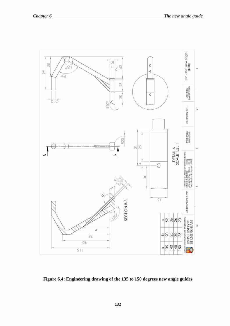
Chapter 6 The new angle guide
132
Figure 6.4: Engineering drawing of the 135 to 150 degrees new angle guides

Chapter 6 The new angle guide
133
6. 3. 2. New base
It was concluded in Chapter 5 that a stainless steel surface roughened using spark
erosion offers the best grip on slippery bone surface. Also, silicone elastomer
would be able to deform to the curved shape of the bone surface and withstand
compression between the guide and bone, which would prevent lateral movement
of the device on the bone surface. Hence, the base of the new angle guide, shown
in Figure 6.5, utilised a combination of attributes provided by the selected
materials to provide good stability and avoid slippage, whilst not harming the
bone.
Figure 6.5: Features of the new base on the 135 degrees new angle guide

Chapter 6 The new angle guide
134
The base of the new angle guide also incorporated the “feedback” feature
discussed in section 4.6.3. This feature proposed to aid the surgeon on the
insertion point for the guide pin by placing the guide pin exit-hole 20 mm from
the front edge of the base. The front end of the base plate was chamfered to slide
easily over the femur surface. The roughened stainless steel surface was also
curved with a radius of 20 mm to complement the radius of curvature of the femur
surface.
6. 3. 3. Material
The new angle guide was designed for both single-use and re-use. Hence, the
material of manufacture should be able to withstand sterilisation by either steam
or irradiation. The angle guide would be made of stainless steel 316L (ASTM F138,
Young’s modulus – 690 MPa, tensile strength – 860-1100 MPa, Poisson’s ratio –
0.33, values sourced from BS 5832-1, 2007 and Ratner et al., 2004) which is the most
commonly used stainless steel for the manufacture of medical devices (Ratner et
al., 2004 and Harper, 2001). A rectangular sheet (25 mm × 15 mm × 2 mm) of
Silastic Q7-4780 (Shore A hardness of 77 from Dow Corning Ltd, Coventry, UK)
would be attached to the base of the guide with Type A Silastic medical adhesive
silicone (Dow Corning Ltd, Coventry, UK). This is a one part silicone adhesive,
often termed as room temperature vulcanising (RTV), and is viable for bonding
stainless steel to silicone elastomer. These adhesives are biocompatible, can
withstand sterilisation and offer good shear, tensile, impact and peel strength

Chapter 6 The new angle guide
135
(Hill, 1998). The adhesive offers easy curing and causes no reaction in the body
even after 90 days of implantation (product data sheet for Silastic medical
adhesive). It was successfully used by Kovick et. al. (1989) to bond Silastic sheets of
1.5 mm thickness to 316L stainless steel compression plates in a study to
investigate the effect of modifying the plate-bone interface with Silastic silicone
elastomer sheets on stress shielding. The stainless steel surface at the bottom of the
base plate would be prepared by using spark erosion method to roughen the
surface to a Ra (surface roughness) value of 8.9 ± 1.50 µm (as measured in Chapter
5). The materials selected for the new angle guide would be able to withstand
sterilisation by either steam or irradiation (Ratner et al., 2004; Hill, 1998; product
data sheet for Type A Silastic medical adhesive silicone).
6. 4. Risk Analysis
Risk analysis, discussed in section 2.3.5.3, aimed to identify the hazards associated
with the new angle guide and determine the control measures to prevent the
hazards. The methodology is described in section 2.3.5.3, and the results are
shown in Table 6.1. The analysis should not be considered exhaustive and was
conducted by the author following consultation with Prof. Maffulli. The analysis
only included the angle guide and did not take into consideration the handle or
the packaging and manufacture of the product.

Chapter 6 The new angle guide
136
Table 6.1: Risk analysis of the new angle guide
Possible
hazard
or failure
mode
Effect of
hazard or
failure
Cause of
hazard or
failure
O S D RPN Control measure
Wrong
insertion
of guide
pin
DHS implant
will not be
placed correctly
as per the
femur's
anatomy; may
lead to non-
union or lag
screw cut-out
Incorrect
placement of
angle guide on
femur
5 6 6 180 Verify with
fluoroscopic images
Wrong angled -
angle guide 1 6 6 36
Pre operation
planning is required
to verify the angle as
per patient's anatomy
Damage
Device does not
function as
intended
'Feel of
bending' on the
handle when
device is
pushed onto the
femur by the
surgeon
1 5 2 10
Appropriate material
selected and FEA was
conducted to verify
the design.
Failure of
bonding of
silicone
elastomer to
stainless steel
1 7 5 35
The selected adhesive
can withstand
sterilisation and is apt
for the device's
materials, loading,
service life and
environment
Fracture/
Breakage
of device
Delay to
surgery
Excessive
application of
force
1 10 2 20
FEA was conducted
on the design to
check for maximum
stresses
Reaction
due to
adhesive
Harmful to
patients
Reaction due to
materials
selected
1 7 10 70
The selected
materials (stainless
steel, silicone
elastomer and
adhesive) are
biocompatible

Chapter 6 The new angle guide
137
The hazard which scored relatively high was the wrong insertion of guide pin due
to incorrect placement of angle guide on femur. The hazard could be prevented by
the surgeon verifying the guide pin position using an image intensifier. This
procedure would be included in the surgical technique to avoid this particular
risk. Finite element analysis was conducted on the angle guide to verify an
absence of noticeable bending of the device when pushed down by the surgeon.
6. 5. Finite Element Analysis (FEA)
6. 5. 1. Overview
FEA, discussed in detail in section 2.3.5.3, was conducted on the new angle guide
to inspect for any undesirable deflection of the design and regions of high stress
whilst in use. The three dimensional model of the new angle guide was created
using SolidWorks CAD software (3DS Daussalt Systemes, Version 2006-2010,
Lowell, MA, USA); and the static analysis on the model was conducted using the
integrated FEA tool called SolidWorks Simulation (COSMOS in versions 2008 and
earlier). The 135 degrees new angle guide was used for the analysis and the
engineering drawing was shown in Figure 6.4.

Chapter 6 The new angle guide
138
6. 5. 2. Pre-processing
Material properties of stainless steel 316L were assigned to the model of the new
angle guide. A 222 N downward compressive force was applied to the handle to
emulate the maximum pushing force generated by the arm of a fifth percentile
man, and 4 N representing the weight of muscles and soft tissues on the angle
guide’s structure when inserted were applied on the model (values of these forces
were derived in section 4.5.3). The device was restrained in all directions at the
bottom of the base plate, as it would be sitting on the bone surface. The model
loaded with forces and restrained at the bottom is illustrated in Figure 6.6.
Figure 6.6: Three dimensional model of the 135 degrees new angle guide loaded (pink
arrows) and restrained (green arrows)

Chapter 6 The new angle guide
139
The mesh size to be used for FEA analysis was determined by plotting a
convergence graph (stress vs. number of nodes). As the mesh size is reduced, the
number of elements (and nodes) are increased, which usually results in an
increase in accuracy of the solution. This step is repeated until the solution is
reached (signified by similar results); and a convergence graph is plotted for the
mesh size to be selected (Avallone et al., 2007). The mesh size selected for the
analysis was 0.65 mm (tolerance of 0.0325 mm, number of nodes - 802755, number
of elements - 554833). It was not possible to conduct the analysis with a mesh size
smaller than 0.60 mm due to limitation of processing power of the computer. The
convergence plot is shown in Figure 6.7, and the meshed model of the new angle
guide is shown in Figure 6.8.
Figure 6.7: Convergence plot to select mesh size for 135 degrees new angle guide.
Green point signify the values of von Mises stress and the number of nodes for the
selected mesh size (0.60 mm)

Chapter 6 The new angle guide
140
Figure 6.8: Meshed model of the new angle guide using mesh size of 1.50 mm
6. 5. 3. Post-processing
Graphical representations of the deformed model, along with the values of the
solutions were displayed. The displacement of the model in units of mm, and
stresses on the model in units of MPa, were presented at the end of the analysis as
results.
The maximum von Mises stress was calculated at the bend in the cylindrical rod as
shown in Figure 6.9a with a value of 400 MPa. The maximum displacement in the
downward direction was 1.2 mm, at the point where the handle would be attached
to the angle guide (Figure 6.9b). The presence of a displacement of 1.2 mm was

Chapter 6 The new angle guide
141
significant as it corresponded to the degree of bending the surgeon would
experience while using the guide. However, it should be noted that a force of 222
N is the maximum pushing force, and would not be expected to be applied
normally. The purpose of the surgeon’s compressive force is to only hold the
guide in position by pushing it against the femur. However, even with these
loading conditions, the stresses were acceptable and below the tensile strength
(1100 MPa) of the material, and hence the material and the design would be able to
withstand the loading conditions while in use.
Figure 6.9: Graphical representation of FEA results on the 135 degrees new angle
guide depicting a) stress in MPa, and b) displacement in mm
The normal arm push force is 26.5 N (Hill, 1998). The FEA study was conducted to
verify the absence of any excessive bending of the angle guide on application of
such force. The point of maximum stress of 48 MPa was noted at the bend on the
cylindrical rod. The value of displacement was 0.15 mm, which can be considered

Chapter 6 The new angle guide
142
trivial and would go unnoticed. Hence, the design of the new angle guide was
able to meet the requirement of “no feel” of bending by the surgeon when in use.
6. 6. The new angle guide
The design of the new angle guide was verified using risk analysis and finite
element analysis, and did not pose any severe concerns or hazards. The design
was able to cover the PDS stated in section 3.9.3.1, and is described in detail in
section 6.3. The new angle guide was proposed to replace the generic angle guide
in the DHS surgical procedure (section 3.6.3.) to permit a minimally invasive
approach using surgical techniques described in section 3.8.3., and would also be
used to insert the new implant, presented in Chapters 8 and 9, to treat proximal
femur fractures. The surgical technique for the new implant is described in
Chapter 10.

Chapter 6 The new angle guide
143
6. 7. Summary
The summarising points of the chapter are listed below.
i. The new angle guide, made of stainless steel 316L, would be able to insert a
guide pin of maximum diameter of 2.5 mm into femurs with neck/shaft
angles in the range of 120 degrees to 150 degrees at 5 degrees increment.
The most prominent features of the new design were: a) that it would
require a maximum incision length of only 23 mm, and b) a new base made
of silicone elastomer and stainless steel surface roughened by spark erosion
method.
ii. Risk analysis of the design of the new angle guide did not present any
major hazards.
iii. FEA was conducted on a three dimensional model of the new angle guide.
The maximum stress recorded was 400 MPa with a bending of 1.2 mm at
application of 222 N surgeon push force and 4 N force due to weight of soft
tissues on top of the device. The maximum stress reduced to 48 MPa with
bending of only 0.15 mm on application of the normal arm push force of
26.5 N. The results suggested that the design was strong enough and would
be able to withstand the forces while in use without noticeable bending.

Chapter 7 The new ergonomic T-handle
144
7.1 Chapter at a glance
7. 1. 1. Chapter Overview Figure 7.1 shows the chapter overview in the form of a flowchart.
Figure 7.1: Flow chart of the chapter structure
7. 1. 2. Keywords
Ergonomics in surgical environment; human factors; handgrips; T-handle
THE NEW ERGONOMIC
T-HANDLE
Generic handle
Re-design with ergonomic factors
Concept
Risk Analysis
New ergonomic T-handle

Chapter 7 The new ergonomic T-handle
145
7. 2. Introduction
Handles of surgical instruments are the first point of contact for the surgeon and
they aid in control of the instrument. A well designed handle would consider the
comfort of the surgeon and aim to reduce the fatigue caused to the surgeon’s
hand. The aim of this research was to introduce an easy and comfortable
minimally invasive surgery (MIS) approach to the implantation of the dynamic
hip screw (DHS). However, MIS results in a decrease in incision size and working
space, which may prove rather disadvantageous to the surgeon and the surgical
staff as it would restrict the movements of the hand and the instruments. This has
led to the designing of new and ergonomic laparoscopic instruments and
operating tables (Berguer, 1999) to make them safer, more effective and
comfortable to use. Although new handles for laparoscopic instruments have also
been designed (Matern et al., 1999; Buchel et al., 2010; Matern et al., 1999), the
conventional T-handle (Figure 3.15) used extensively in the DHS surgical
procedure has not been revaluated and redesigned considering ergonomic factors.
The handle connects with various instruments like the angle guide and the
impactor during the course of the surgery (Baumgaertner, 1998).
T-handles are supplied by every manufacturer in their DHS instrument set. The
design analysed in this research is of the generic T-handle supplied by most
manufacturers including Synthes GmbH (Solothurn, Switzerland) and Smith &
Nephew plc (London, UK). Certain manufacturers like Stryker (Kalamazoo,
Chapter 7 The new ergonomic T-handle
146
Michigan, USA) and B. Braun Melsungen AG (Melsungen, Germany) do
manufacture T-handles with ergonomic features. However, there is no data
available either through academic or corporate publications regarding their
dimensions, material or ergonomic factors, which would assist in analysing their
design and compare them to the points stated in the PDS (section 3.9.3.2).
However, it was considered important to include an ergonomic T-handle with the
new angle guide, and also as part of the instrument set for the new implant.
The novelty of this redesign process was that it reviewed the literature for
ergonomic principles of a handle from other industries and skilled professions
such as material handling (Karwowski and Marras, 2003), anthropometry
(Pheasant 2002) and manufacturing (Das et al., 2005). These findings were then
integrated with the requirements as stated in BS EN 12011 (1998), especially the
material requirements of a medical device, to be used in a sterile surgical
environment. This was to ensure that the T-handle classified as a class I medical
device (Medical Device Directive, 1993) on its own right. The resulting T-handle
concept design could also be used for instruments in other surgical procedures.

Chapter 7 The new ergonomic T-handle
147
7. 3. Design objectives of a new T-handle
The general design objectives of the new T-handle are listed below.
i. The T-handle should be designed to be used with instruments required to
implant a DHS.
ii. The handle should integrate ergonomic principles to make it comfortable to
use by surgeons and surgical staff in MIS.
iii. The handle would be designed for use in a single-use and a re-use market
and hence the material of construction should be able to withstand
sterilisation as per standards BS EN 554 (1994), BS EN 556-1 (2001) and BS
EN 556-2 (2003).
iv. The design specifications for the new T-handle should be in accordance
with the standards and regulations for surgical instruments, i.e. BS EN
12011 (1998).
7. 4. Existing T-handles
The shape and dimensions of a current T-handle were taken from the detachable
T-handle (Figure 3.15) used with the DHS surgical instruments, and manufactured
by Sushrut Surgicals Pvt. Ltd. (Pune, Maharashtra, India). The engineering
drawing of the generic T-handle (without locking mechanism) is shown in Figure

Chapter 7 The new ergonomic T-handle
148
7.2. This design was similar to the T-handle supplied by other orthopaedic medical
device manufacturers such as Synthes GmbH (Solothurn, Switzerland). The
dimensions were measured using a digital vernier caliper (resolution of 0.01 mm
and accuracy of ±0.03 mm, Fisher Scientific UK Ltd., Loughborough,
Leicestershire, UK). The handle was made of stainless steel, and was a plain
hollow cylinder with an outer diameter of 15 mm and inner diameter of 12 mm.
The shaft of the instrument was connected exactly at the centre, and the length of
the handle was 95 mm.
The design of the generic T-handle was compared to the PDS mentioned in section
3.9.3.2. Although the T-handle performs the function of a handle for the
instruments and is able to be sterilised, the main reasons because of which the
handle was not considered ergonomic are listed below.
1. The length of the handle is shorter than 120 mm causing the ends to dig
into the palm of the hand and not allowing adequate control due to the lack
of space for all the fingers and thumb to fit on it.
2. The diameter of the handle is smaller than 30 mm causing the fingers to
overlap and not offer a comprehensive grip to the user.
3. Stainless steel surface was too hard to touch, and hence not comfortable to
hold. The presence of sharp edges at the ends of the handle could be
injurious to the user or the patient.

Chapter 7 The new ergonomic T-handle
149
Figure 7.2: Engineering drawing of the generic T-handle (without locking
mechanism) manufactured by Sushrut Surgicals Pvt. Ltd. (Pune, Maharashtra,
India)

Chapter 7 The new ergonomic T-handle
150
Additionally, a survey was conducted by the author and Dr. D.E.T. Shepherd, and
organised by Prof. N. Maffulli on 7th December 2007 at the City General Hospital
(Stoke-on-Trent, UK). The purpose of the survey was to determine an appropriate
material that would be most comfortable to use for the interface of the
instrument’s base with the bone. This survey was first mentioned in section 4.6.7,
and further details could be found in Appendix A. Within the survey, surgeons
were also asked to compare two lengths (95 mm and 115 mm), and two diameters
(25 mm and 30 mm) of a handle, and rate them based on the comfort fit it
provided in their hands. Although the results of the survey were inconclusive,
there was a definite inclination towards a longer (115 mm) and thicker (30 mm)
handle. Two out of the ten respondents also asked for a better handle than the one
they use in surgery at present. The findings of the survey were not used in the
design process due to the inconclusive results and the small sample size.
7. 5. Design requirements for the new DHS T-handle
7. 5. 1. Overview
The designing of the new T-handle integrated ergonomic factors into the medical
design device process. The integration of ergonomic stages in the design process
of a hand tool comprises of understanding the requirements and the collaboration
of the user, the product and the task/ environment (Karwowski, 2001). Hence, it
Chapter 7 The new ergonomic T-handle
151
was important to specify ergonomic factors and the type of task along with the
intended function of the device, and state the specifications of the device
accordingly. This section also provides the justification of the statements in the
PDS (section 3.9.3.2).
7. 5. 2. Function
During the surgical procedure of the DHS implant (section 3.6.3.1), the T-handle is
used with a variety of instruments. The purpose of the handle can be broadly
classified into two actions – i) push and hold while using the angle guide, and ii)
torque application while using the insertion wrench and the lag screw tap. The
handle should be effective and comfortable during its execution with the
instruments mentioned for the respective applications.
7. 5. 3. Grip
Handles could be used for a variety of functions. The handle should be designed
after understanding the hand grips while performing the various functions. It is
suggested that the prehensile movements of the hand, which includes the
grasping or gripping of objects can be divided into two categories of gripping
action (Napier, 1956) – 1) power grip or cylinder grip (Figure 7.3a), where the
object is held with the fingers and thumb against the plane of the palm; 2)
precision grip or ball grip (Figure 7.3b), where the object is pinched between the

Chapter 7 The new ergonomic T-handle
152
fingers and the thumb. The T-handle in the DHS surgery would be required to be
used during push and hold after manoeuvring and torque applications, which is a
combination of both precision and power grip tasks respectively. It should hence
be possible for the handle to be held with either of the grips.
Figure 7.3: Different grips of the hand – a) power grip with the object placed in the
palm of the hand and the fingers and thumb curl around to hold it, b) precision grip
with the object held by pinching it between the finger(s) and thumb
7. 5. 4. Size
It is important for the handle to fit the hand of a variety of surgeons with different
hand sizes. The relevant dimensions of 5th, 50th and 95th percentile British adult
men and women are listed in Table 7.1 (Pheasant, 2002), along with the dimension
notation in Figure 7.4. It is important that these dimensions are considered,
especially if one handle is designed to suit all the different hand sizes. The hand

Chapter 7 The new ergonomic T-handle
153
breadth will determine the length of the handle, and the hand length and
thickness could be used to determine the diameter of the handle.
The length of the handle would depend on the anthropometric data provided. It is
recommended to design a longer handle to prevent the digging of the handle into
the palm of the user. A minimum handle length of 100 mm, with 125 mm being
more comfortable is suggested for handles held axially for power grip, where all
four fingers would make contact. A length of 125 mm, with an additional length of
12.5 mm for users with gloves is recommended for a precision grip handle (Das et
al., 2005).
Figure 7.4: Sketch of a hand depicting the anthropometric data tabulated in Table 7.1

Chapter 7 The new ergonomic T-handle
154
Table 7.1: Anthropometric measurements of hand for design of hand tool handles.
Dimensions are in mm
No Dimensions Men Women
5th %ile
50th %ile
95th %ile
5th %ile
50th %ile
95th %ile
1 Hand breadth (metacarpal) 78 87 95 69 76 83
2 Hand breadth (across
thumb) 97 105 114 84 92 99
3 Hand thickness
(metacarpal) 27 33 38 24 28 33
4 Hand length 173 189 205 159 174 189
5 Thumb Length 44 51 58 40 47 53
6 Thumb Breadth 20 23 26 17 19 21
7. 5. 5. Cross section
The cross section of the handle depends on the use of the instrument. A
rectangular handle provides more purchase, however cylindrical handles are more
comfortable to hold (Cochran et al., 1986). The diameter of the handle should not
be too large, as the requirement of substantial force for grip leads to muscle fatigue
in a relatively short time. In contrast, a handle with a small diameter, will not
allow much force to be generated leading to local tissue pressures due to the
shortening of the finger muscles (Das et al., 2005). The literature recommends a
handle diameter in the range of 30 to 50 mm (Pheasant, 2002; Cochran et al., 1986).

Chapter 7 The new ergonomic T-handle
155
The lower end of the range would be best for flexibility and dexterity, whereas the
upper end of the range would provide the maximum torque (Karwowski and
Marras, 2003). It was the aim of this process to design a comfortable handle and
thus the surgical T-handle should be circular with a diameter in the lower range of
30 to 50 mm.
7. 5. 6. Material
The material should withstand multiple cycles of steam sterilisation (autoclave) to
allow the handle to be re-used; irradiation sterilisation that would be used prior to
packaging of the handle if it is to be supplied in a single-use market. The outer
material should be soft to touch for comfort, but at the same time the inside should
offer structural integrity to not get damaged during falls, and to provide a firm
grip. The design would need to use layers of different materials to achieve the
requirements. The material at the surface of the handle should neither be too
rough, nor too smooth. A compromise of the two would ensure that the handle
provides enough friction to avoid slipping, and at the same time avoid abrasion of
the user’s hand.
7. 5. 7. Shape
The main principle in an ergonomic design of hand tools is to fit the tool to the
hand (Berguer and Hreljac, 2004). The shape of the handle should conform to the

Chapter 7 The new ergonomic T-handle
156
curvature of the palm engaging with the handle surface. Pheasant (2002) suggests
a minimum radius of curvature of about 25 mm for the surface area which
engages with the hand. A double frustum handle with a reducing diameter along
both the axis from the centre would provide more comfort as this would allow
each finger to grip at a different handle circumference. This was demonstrated in
an experiment where double frustum handles scored higher than handles with
oval cross section for comfort (Kong et al., 2004). Maximising the grip surface area
would enable the pressure to be distributed over a much larger area, hence not
creating any high pressure at the palm-handle interface. This would also reduce
shear stress on the skin, thereby reducing abrasion (Pheasant and O’Neill, 1975).
7. 6. Evolution of a new concept
7. 6. 1. Concept 1
Concept 1, shown in Figure 7.5, consisted of a double frustum cylindrical handle
with the diameter reducing from 40 mm at the centre to 30 mm towards the two
ends. The bottom part was finger shaped for a better grasp of the handle. The
length of the handle was 125 mm, and was sufficiently long even for a 95th
percentile man’s hand (114 mm) to not dig into his palm. The design gave
preference to a power grip, and the circular cross section to provide comfort.

Chapter 7 The new ergonomic T-handle
157
Figure 7.5: Concept 1 of a new ergonomic T-handle
The skeleton of the handle would be made of stainless steel 316L, which is the
same as the material of the instruments with which it would be used. The metal
would be overmolded with a soft polymer, which can withstand both irradiation
and autoclave, for a comfortable grip.
However, the concept seemed unable to provide comfort to different hand sizes
and grip for different tasks. These limitations were mainly due to the double
frustum shape and the finger shaping of the handle. A surgeon with a smaller
hand would find it difficult to grasp the large diameter at the centre. The thumb
would be wrapped around the handle, which would restrict the grip to a power
grip. These were important factors as the T-handle was to be designed for use by a
variety of surgeons of different built and with instruments of different
applications.

Chapter 7 The new ergonomic T-handle
158
7. 6. 2. Concept 2
Concept 2 evolved from Concept 1 with an attempt to overcome the limitations
discussed in the previous section. The new concept, shown in Figure 7.6, was a
curved cylinder of constant diameter with a length of 125 mm. The curved bottom
of Concept 1 was replaced with curved rectangular cross-sectioned bars. This
addressed the issue of grasping with fingers of different length, and also reduced
the inconvenience caused to small hands due to the large diameter towards the
centre. The rectangular cross sections also provided more purchase, as was
discussed in 7.5.5. The handle curved beyond the cylinder on both ends to provide
support to the users’ thumbs (the curved extensions on both ends will henceforth
be termed as phalanges). This increased the gripping area without increasing the
length of the handle. It is pointed out by Phesant (2002) that although the basic
power grip requires the thumb to wrap around the back of the finger for stability
and gripping force, extra control, which is provided by precision grip, could be
attained by moving the thumb along the shaft of the tool handle. Hence, with the
new design, the thumb could rest along the cylinder onto a phalange to provide
extra control over the handle. It can also be noted that finger shaping was avoided
as the target users could have a wide range of different finger sizes. Concept 2
would utilise the same material combination as concept 1. The concept fulfilled all
the design requirements laid out, and hence was taken forward to the detail
design stage of the medical device design process.

Chapter 7 The new ergonomic T-handle
159
Figure 7.6: Concept 2 of a new ergonomic T-handle
7. 7. The new ergonomic T-handle in detail
7. 7. 1. Overview of the design
The new T-handle was intended to function as a comfortable interface for the user
to hold, grip and use appropriate surgical instruments without causing any injury
and at the same time result in minimum tiredness to the user
In a surgical environment, the T-handle predominantly would require a power
grip with some allowance for control and flexibility to rotate the tool attached to
the handle. Taking this into consideration, the length of the ergonomic T-handle
was 125 mm. This allowed the handle to extend beyond the palm of the 95
percentile man (114 mm), along with all the diversities. The additional length
allowed for the thumb to be placed along the shaft to enhance the dexterity of the

Chapter 7 The new ergonomic T-handle
160
surgeon, while using the surgical instrument in a tight working space. The handle
included phalanges on both ends. This accommodated for either handedness, and
also for larger hand sizes. The provision of phalanges would encase the fingers,
and prevent the dropping of the tool even with a lose grip. The phalanges were
designed to be wide and long enough (30 mm × 60 mm) to accommodate 95
percentile man’s thumb with a width of 26 mm. A rendered three dimensional
image of the new T-handle, drawn on SolidWorks CAD software (3DS Daussalt
Systemes, Version 2010, Lowell, MA, USA) is shown in Figure 7.7.
The handle was cylindrical with constant diameter of 30 mm and a radius of
curvature of 250 mm. The rectangle section with width of 10 mm extruded 50 mm
towards the centre and was curved with a radius of curvature of 110 mm, from the
phalanges on both sides. The provision of the rectangular sections was to
accommodate the varying lengths of different fingers of a hand and also different
hand sizes of surgeons. The combination of circular and rectangular cross section
would provide comfort and grasping purchase to the surgeon. A provision for the
shaft of the instrument to be inserted was provided at the centre. Figure 7.8 shows
an engineering drawing of the handle.

Chapter 7 The new ergonomic T-handle
161
Figure 7.7: A three-dimensional rendered image of a new ergonomic T-handle for use
with instruments during MIS of DHS
The handle was only meant for use by a skilled user, and was to be sterilised using
autoclave if re-used.

Chapter 7 The new ergonomic T-handle
162
Figure 7.8: Engineering drawing of the new ergonomic T-handle

Chapter 7 The new ergonomic T-handle
163
7. 7. 2. Material of the new T-handle
The handle was designed for single-use and re-use markets, and hence, it would
have to withstand sterilisation through irradiation and through steam. This was an
important criterion to consider while selecting the materials to match the
requirements of an ergonomic T-handle. It was also important to consider the
compatibility of the different materials and cost of manufacturing a complicated
shape when choosing the material. A curved metal rod would be overmolded with
polypropylene (PP) to give the desired shape, and then would be overmolded
again with thermoplastic polyolefin (TPO) elastomer to give a soft and
comfortable touch. Figure 7.9 shows a cross-section of the handle with the
different materials. The metal underlay would be the same as the one used to
fabricate the instrument (Stainless Steel 316L). PP is a cheap material, can be easily
processed (Hill, 1998) and is able to withstand both steam and irradiation
sterilisation (Massey, 2005). PP would be used to give the handle the ergonomic
shape over the metal cylinder. Finally TPO, which is resistant to radiation and
autoclaving as well (Massey, 2005), would provide the soft touch while reducing
slippage, possibility of colour coding the instrument and an option of brand
embossing. The colour coding and brand embossing option with the TPO could
be customised for easy indication of surgical step and the type of instrument
(discussed in section 10.4.2).

Chapter 7 The new ergonomic T-handle
164
Figure 7.9: The three layers of materials to be used in the new t-handle to combine
ergonomic interface with the handle and rigidity of the structure
7. 8. Design verification
The design of the new ergonomic T-handle was verified using a risk analysis. The
FMEA method, described in section 2.3.5.3, was conducted by the author. The
results of the analysis are shown in Table 7.2. The analysis should not be
considered exhaustive, and did not include the packaging, labelling and
manufacture of the handle.
Although none of the risks scored high in the analysis, all the identified hazards
described in table 7.2 were addressed with effective control measures.

Chapter 7 The new ergonomic T-handle
165
Table 7.2: Risk analysis conducted with the FMEA method on the new T-handle
Possible
hazard or
failure mode
Effect of
hazard or
failure
Cause of
hazard or
failure
O S D RPN Control
measure
Damaged
Device does
not function as
intended
Sterilisation 3 7 1 21
Materials
selected which
can withstand
sterilisation
procedures
Bending of
handle 1 7 1 7
Stainless steel
will form the
skeleton of the
design
Break at
shaft/handle
junction
1 7 1 7
Stainless steel
(material of
instrument
shaft) used
Unsafe to user Injury to
surgeon
Sharp edges 2 7 3 42
Sharp edges
were avoided in
the design. Soft
touch layer for
handle - hand
interface
Slip out of hand 1 2 10 20
Appropriate
material
selected
Uncomfortable
to user Fatigue
Handle size not
appropriate 3 5 5 75
Designed as per
available
anthropometric
data
Handle
contaminated
with blood
Harmful to
patients
Not sterilized
before re-use 1 7 10 70
Supply
information on
sterilisation
procedures
Breaking of
handle
Delay to
surgery
Materials not
strong enough 1 10 2 20
Designed with
appropriate
materials

Chapter 7 The new ergonomic T-handle
166
7. 9. The new ergonomic T-handle
The design of the new T-handle is described in detail in section 7.7, and
successfully underwent the risk analysis in section 7.8. The T-handle was designed
to replace the existing generic design being used in the DHS surgery described in
section 3.6.3. It would also be used with the instruments in the minimally invasive
surgical technique for the new implant developed in Chapters 8 and 9. The
surgical technique of the new implant is shown in Chapter 10.
7. 10. Summary of the design process
The summarising points of this chapter are listed below.
i. Ergonomic factors including size, shape, function, etc. were considered in
the medical device design process for a new T-handle.
ii. The new T-handle would be able to provide a comfortable interface to
surgeons with varied hand sizes for using instruments of the DHS surgery.
iii. The material of the T-handle combined the stiffness of stainless steel with
the malleability of PP with the soft touch of TPO – all materials able to
withstand sterilisation procedures to manufacture a comfortable yet firm
surgeon’s T-handle.

Chapter 8 Concept of a new implant
167
8.1 Chapter at a glance
8. 1. 1. Chapter overview Figure 8.1 shows the chapter overview in the form of a flowchart.
Figure 8.1: Flowchart of the chapter structure
8. 1. 2. Keywords BS 3531-15 (1992); BS EN ISO 14630 (2009); BS EN ISO 14602 (2010); dynamic hip screw
CONCEPT OF A NEW IMPLANT
Generic DHS implant
Define design objectives
Idea generation and evolution conforming to design requirements
Design requirements according to standards
Concept of a new implant based on DHS principle

Chapter 8 Concept of a new implant
168
8. 2. Introduction
The Dynamic Hip Screw (DHS), discussed in Chapter 3, is the standard implant
used to treat proximal femur fractures (Chirodian et al., 2005; Harrington et al.,
2002; Esser et al., 1986). In brief, the DHS assembly consists of a collapsible lag
screw inserted into the femoral neck and head that slides within an angled side
plate attached to the lateral side of the femur. The compression at the fracture site
promotes bone-on-bone contact and results in fracture healing while decreasing
loading on implant. The implant is discussed in more detail in section 3.6 and is
shown in Figure 8.2.
Figure 8.2: Generic dynamic hip screw (DHS) manufactured by Smith & Nephew plc.
(London, UK)

Chapter 8 Concept of a new implant
169
A new angle guide (Chapter 4 to 6) and a new handle (Chapter 7) were designed
in this research, which would facilitate easy implantation of the existing DHS
implant through an incision of 30 mm. The DHS implant was also identified in
section 3.9 for redesign to allow for easier implantation in minimally invasive
surgery (MIS). Since the introduction of AO DHS implant in 1979, the design of
the generic implant has not been modified greatly. Owing to its success and
decades of use, the surgical techniques and the implant’s use has established itself
as the “gold standard” for the treatment of proximal femur fractures (Parker and
Handoll, 2009). New implants, most prominently the Gotfried PC.C.P., are based
on the principles of the DHS and also combine the benefits of MIS (discussed in
section 3.7). However, they have yet not replaced the DHS as the preferred device.
The reasons may include a steep learning curve for the new surgical technique
(Scuderi and Tria, 2010), need to increase the hospital inventory as the implants
require new sets of tools for implantation (Ho et al., 2008), and the existence of
similar surgical approaches (section 3.8.3) that allow smaller incisions with
minimum modification to the generic DHS surgery (instruments and technique).
The research presented in Chapters 8, 9 and 10 describes a detailed design process
of a new implant to treat proximal femur fractures. The new implant was based on
the sliding screw principle of DHS, and allowed for implantation through an
incision length of less than 30 mm. It was attempted to build on surgeon’s
experience with the generic DHS instruments and surgical technique by keeping
them as similar as possible for the new implant.
Chapter 8 Concept of a new implant
170
8. 3. Design objectives
The objectives of the design process were to -
a) redesign the established and popular DHS implant to allow easy insertion
and implantation through an incision length of less than 30 mm;
b) retain the principle of sliding of the lag screw into the side plate to promote
bone on bone impact for faster healing and weight bearing; and
c) retrieve the experience of surgeons with the surgical technique of
implanting a DHS by utilizing similar instruments and surgical procedure
steps for the new implant to avoid a steep learning curve.
8. 4. Design specifications
8. 4. 1. Overview
The design specifications of a new implant, stated in section 3.9.3.3, were prepared
in accordance with clauses stated in the general requirements of surgical implants
(BS EN ISO 14630, 2009), particular requirements of implants for osteosynthesis
(BS EN ISO 14602, 2010), and requirements of devices for the fixation of adult
femur ends (BS 3531-15, 1992). Information for the topics was collected from
published literature on existing DHS implants and through discussion with Prof
N. Maffulli (Consultant Surgeon). Certain topics such as sliding mechanism (8.4.3)

Chapter 8 Concept of a new implant
171
are not mentioned in any of the standards. However, they were added to enable a
comprehensive requirement discussion before designing a concept. The
specifications for devices supplied by competitors, shown in Table 3.1, were used
as benchmarks.
8. 4. 2. Functional characteristics
The new implant would be a non-active (does not depend on electrical energy or
any sorts of power apart from that directly generated by the human body or
gravity - BS 3531-15, 1992) implantable device to be totally introduced into the
human body by means of surgical intervention. The existing DHS implant consists
of two main parts - (A) the fixation screw - type C fixation (clause 4 of BS 3531-15,
1992) and (B) the fixed angled plate with a barrel. The concept is for the screw to
slide down the barrel, which allows for compression of the fracture site, and also
bone-on-bone contact. The new implant should retain the basic principle of the
fixation screw sliding down the angled plate. The implant should be designed to
allow for removal from the human body if required, and would be designed for
single-use only.
8. 4. 3. Fracture treatment
The design and purpose of the new implant was based on the existing generic
DHS and angled side plate implant. Like the DHS, the new implant was intended

Chapter 8 Concept of a new implant
172
for implantation for treatment of fractures of the proximal femur in adults. The
implant would not be designed for paediatric use because of the requirement for
different plate and lag screw dimensions. The implant would not allow for
rotation of the fracture fragments at the site, and it would promote faster healing
of the fracture and early weight bearing due to the sliding connection between the
lag screw and the angled side plate.
As suggested by Prof. N. Maffulli, following the surgical treatment, the device
would be designed to allow immediate weight bearing as able by the patient. The
patient is expected to maintain a low activity level and would return to functional
weight bearing some 6 to 12 weeks after implantation of the device.
8. 4. 4. Sliding mechanism
Implant cut-out is a major complication after repair of proximal femoral fractures
(Canale, 2002). The rate of cut-out was significantly reduced as the implants
shifted from mostly rigid fixation principles to sliding devices such as the DHS
(Linden et al., 2006). The sliding of lag screw in a DHS offers biomechanical
advantages as the hip gets more stable by impaction of bones and medial
displacement of the femoral shaft. The shortening of the lever arm also reduces the
stresses applied to the implant and bone (Flores et al., 1990).
Complications and fixation failure is also attributed to excessive or insufficient
sliding of the lag screw (Kim et al., 2001; Gundle et al., 1995). Kim et al. (2001)

Chapter 8 Concept of a new implant
173
reported that excessive sliding may also result in extrusion of the lag screw from
the lateral wall; other complications may include displacement of fracture,
shortening of the affected limb and hip pain with sliding of more than 20 mm. In a
study of 100 patients with unstable intertrochanteric fractures by Gundle et al.
(1995), a slide of 20.5 mm was required during the healing process in patients
treated with the DHS. It was also shown that slides of less than 10 mm were a
significant predictor of fixation. Success in fracture fixation was always achieved
in the study when the range of available slide was 10 mm to 29 mm. The Targon
FN implant (B. Braun Melsungen AG, Melsungen, Germany), which allows for
minimally invasive surgery (discussed in section 3.8.2) permits a maximum lag
screw slide of 20 mm.
The design of the new implant should incorporate a sliding connection of 20 mm
between the lag screw and the angled plate to allow bone impaction for faster
healing and early weight bearing. The design should also accommodate a
clearance of 1 mm between the outside surface of the lag screw and the inside
surface of the barrel, as mentioned by BS 3531-15 (1992).
8. 4. 5. Material
Although the implant would be designed for single-use, the device should be
supplied sterile for immediate use in the operating theatre during trauma surgery,
and hence should be able to withstand sterilisation through irradiation. Gamma

Chapter 8 Concept of a new implant
174
radiation sterilisation is an effective, economical and proven sterilisation process
for package of medical devices (Hill, 1998). The material should also be
biocompatible for implantation into the human body for a long period of time
(minimum period of 90 days as mentioned by Prof. N. Maffulli). The material
should also be strong enough to withstand the loading that shall be subjected on
to the implant during the course of healing of the fracture.
8. 4. 6. Lag screw
The generic DHS lag screw is a Type C fixation screw (clause 4 of BS 3531-15,
1992), which is designed to be inserted only after preparation of the femoral neck
and head (drilling and tapping as described in the surgical technique in section
3.6.3.2). The fixation screw could be divided into two regions – a) screw region
and b) sliding region, as shown in Figure 8.3. The screw region grips onto the
femoral head through purchase of the cancellous bone in the head of the femur.
This hold is essential for a successful fracture fixation. The sliding region is a
cylinder with two opposite sides flattened. The outer shape of the sliding region
on the lag screw corresponds to the inner flattened surface of the barrel, restricting
rotation of the lag screw.
The length of lag screw to be used in a particular surgery is dependent on the
patient’s femoral anatomy. The length is measured during the course of surgery as
described in section 3.6.3.2. According to the standard BS 3531-15 (1992), the range
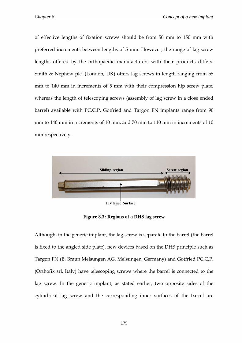
Chapter 8 Concept of a new implant
175
of effective lengths of fixation screws should be from 50 mm to 150 mm with
preferred increments between lengths of 5 mm. However, the range of lag screw
lengths offered by the orthopaedic manufacturers with their products differs.
Smith & Nephew plc. (London, UK) offers lag screws in length ranging from 55
mm to 140 mm in increments of 5 mm with their compression hip screw plate;
whereas the length of telescoping screws (assembly of lag screw in a close ended
barrel) available with PC.C.P. Gotfried and Targon FN implants range from 90
mm to 140 mm in increments of 10 mm, and 70 mm to 110 mm in increments of 10
mm respectively.
Figure 8.3: Regions of a DHS lag screw
Although, in the generic implant, the lag screw is separate to the barrel (the barrel
is fixed to the angled side plate), new devices based on the DHS principle such as
Targon FN (B. Braun Melsungen AG, Melsungen, Germany) and Gotfried PC.C.P.
(Orthofix srl, Italy) have telescoping screws where the barrel is connected to the
lag screw. In the generic implant, as stated earlier, two opposite sides of the
cylindrical lag screw and the corresponding inner surfaces of the barrel are

Chapter 8 Concept of a new implant
176
flattened to prevent rotation of the screw inside the barrel, which provides
rotational stability to the fracture. However, the non-circular cross sections of the
lag screw and the inner surface of the barrel demands that the side plate be
inserted vertically-straight so that the barrel is able to slide over the pre-inserted
lag screw (Figure 8.4). This problem could be resolved with a telescoping screw
where the barrel and lag screw are inserted together as one part. Additionally, the
latest implants offer multiple lag screws to assist in rotational stability of the
fracture.
Figure 8.4: Requirement of inserting the side plate vertically straight to slide over the
pre-inserted lag screw
It was important for the lag screw in the new implant to provide rotational
stability to the fracture, adequate purchase of bone at the femoral head for a strong
hold, simple insertion with a minimally invasive approach, and availability of
different lengths to cater to patients with differing femoral anatomy.
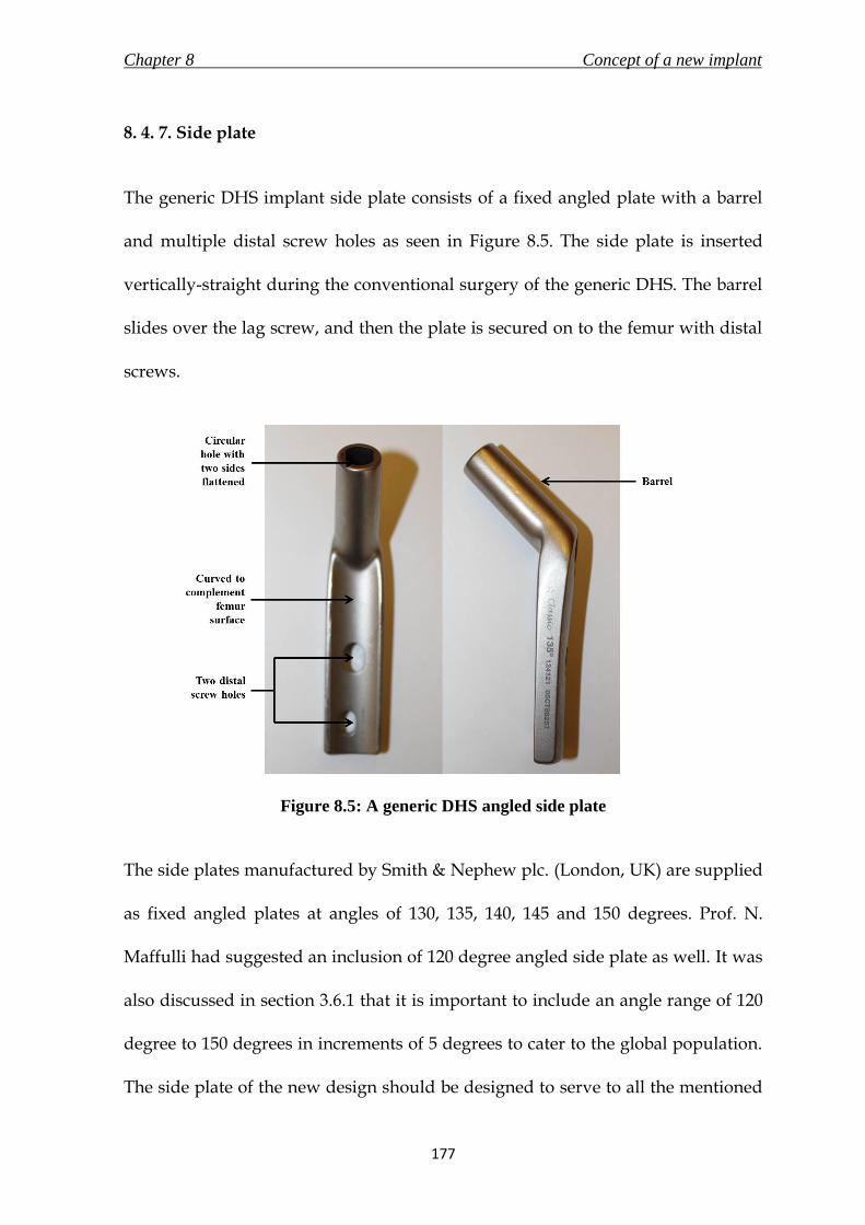
Chapter 8 Concept of a new implant
177
8. 4. 7. Side plate
The generic DHS implant side plate consists of a fixed angled plate with a barrel
and multiple distal screw holes as seen in Figure 8.5. The side plate is inserted
vertically-straight during the conventional surgery of the generic DHS. The barrel
slides over the lag screw, and then the plate is secured on to the femur with distal
screws.
Figure 8.5: A generic DHS angled side plate
The side plates manufactured by Smith & Nephew plc. (London, UK) are supplied
as fixed angled plates at angles of 130, 135, 140, 145 and 150 degrees. Prof. N.
Maffulli had suggested an inclusion of 120 degree angled side plate as well. It was
also discussed in section 3.6.1 that it is important to include an angle range of 120
degree to 150 degrees in increments of 5 degrees to cater to the global population.
The side plate of the new design should be designed to serve to all the mentioned

Chapter 8 Concept of a new implant
178
neck/shaft angles. The inner surface of the generic side plate, which interfaces
with the lateral femur surface, is curved to correspond to the curvature of the
surface of the bone. As discussed in Chapter 4, the radius of curvature of the
femoral surface is in the range of 13 to 18 mm, and hence the radius of curvature
of the inner surface of the new side plate should be 20 mm to accommodate
variability due to difference in population.
The length of incision made during a DHS surgery depends on the length of the
side plate used (surgical technique by Michael R. Baumgaertner, Smith & Nephew
plc., London, UK) because of the vertically straight insertion of side plate as
discussed in section 8. 4. 7. A four-hole side plate DHS is a commonly used side
plate for the treatment of intertrochanteric hip fractures (Laohapoonrungsee et al.,
2005). A rare occurrence of side plate pull-out or breakage has resulted in a few
studies to evaluate the implications of reducing the length of the side plate by
decreasing the number of distal screw holes (Laohapoonrungsee et al., 2005; Yian
et al., 1997; McLoughlin et al., 2000 and Bolhofner et al., 1999). In their
biomechanical studies, Yian et al. (1997) found no advantage in inserting more
than three distal screws to achieve adequate side plate fixation; Mcloughlin et al.
(2000) did not establish any significant difference in the stability of two and four
holes DHS implants. Bolhofner et al. (1999) did not report any failure in two holes
side plate DHS fixation in 69 patients; and it was also concluded by
Laohopoonrungsee et al. (2005) after their trial on 112 intertrochanteric fractures
that two holes side plate DHS is adequate for fixation of such fractures. The length

Chapter 8 Concept of a new implant
179
of a standard barrel side plate manufactured by Smith and Nephew plc. (London,
UK) with 2 screw holes is 60 mm, with a 20 mm increase in length for every
additional slot. These findings were important as a shorter side plate in the new
design would aid in reducing the length of incision required. It should also be
noted that a minimum of two distal screw holes would be required in the side
plate of the new implant.
A study by Jewell et al. (2008) showed that a side plate of a DHS with fixed angle
locking screws would reduce the risk of DHS failure. The experimental results
showed a statistically significant increase in the number of cycles to failure for
locking plates compared to standard plates. The same research also argued that a
locking plate would have biological advantages over standard plates as they do
not compress the bone. This is because a standard plate would grip the bone by
friction, which is created by compression of the plate against the bone by the
screws. This phenomenon would be absent in case of locking screws and hence
would prevent a decrease in cortical thickness and cancellous transformation of
the bone. The idea of locking plate is applied by Synthes Holding AG (Solothurn,
Switzerland) in the form of “combi-hole” design in their side plates. The “combi-
hole” allows for insertion of both conventional and locking screws for fixation.
The distal holes for either locking or conventional screws in the new implant
would have to conform to the dimensions and tolerances stated in standards on
specifications for holes and slots for use with screws in bone plates (BS 3531-23.2,
1993).

Chapter 8 Concept of a new implant
180
8. 4. 8. Surgical Technique
The conventional surgical technique of implanting a DHS and side plate for the
treatment of proximal femur fractures was described extensively in 3.6.3.2. The
surgical procedure for the new implant should try and retain the surgical steps
and instruments used in the conventional surgery. This would enable faster
acceptance by the surgeons due to a gentler learning curve and less burden on the
hospital inventory and costs.
However, the most important objective of the new implant was to require an
incision length not larger than 30 mm. The existing generic DHS requires the lag
screw to be advanced first and set in a position such that the angled plate is able to
fix on to it. The Percutaneous Compression Plate (PC.C.P., Orthofix srl, Italy) is an
existing implant, which has evolved from the DHS, and was discussed in detail in
section 3.8.2. The PCCP allows for minimally invasive surgery and the surgical
technique involves securing the plate before advancing the lag screw (Peyser, et
al., 2005). This method makes it easier to assemble the implant through a smaller
incision because of the new locking method between the lag screw and side plate.
Unlike the conventional surgical method, the side plate is first inserted through a
small incision, slid down the lateral femur into position and secured. This method
now permits the lag screw to advance into the femoral head through the angled
plate through the same small incision without any requirements of a particular
insertion method.

Chapter 8 Concept of a new implant
181
The surgical technique for the new implant should build on the existing
conventional surgical procedure for the DHS implant, and not require a steep
learning curve. However, it should also include steps that would result in
reducing the incision length to less than 30 mm, and aid in easy and comfortable
insertion.
8. 4. 9. Dimensions
The dimensions of the existing DHS and side plate implant assembly are shown in
Figure 8.6 and tabulated in Table 8.1. The nomenclature of dimensions as shown in
Figure 8.6 is in accordance with clause 5.1 of standard BS 3531-15 (1992). The
standard barrel two holes side plate of 60 mm angled at 135 degrees (catalogue no.
12-4121) and lag screw with an effective length of 105 mm (catalogue no. 12-1110)
are part of the DHS implant set manufactured by Smith & Nephew plc. (London,
UK). The mentioned dimensions were used as reference for the design of the new
implant. The dimensions were measured using digital vernier callipers (resolution
of 0.01 mm and accuracy of ±0.03 mm, Fisher Scientific UK Ltd., Loughborough,
Leicestershire, UK)

Chapter 8 Concept of a new implant
182
Table 8.1: Dimensions of a generic 135 degrees DHS implant shown in Figure 8.6
No Dimension mm
1 Effective screw length 105
2 Thread length 21
3 Barrel length 38.1
4 Shaft diameter 9
5 Thread diameter 12.7
6 Barrel diameter 13
7 Effective plate length 60
8 Plate thickness Ranges from 6 at bottom
to 10.5 at the top end
Figure 8.6: Nomenclature of dimensions of a generic 135 degrees DHS implant in
accordance to standard BS 3531-15 (1992)

Chapter 8 Concept of a new implant
183
8. 4. 10. Mechanical testing
The fixation device should be subjected to the testing method ASTM F 384 (2006),
which describes the static loading and fatigue testing methods for metallic angled
orthopaedic fracture fixation devices. The mechanical testing conducted on the
device is discussed in more detail in Chapter 9.
8. 5. Evolution of a concept
8. 5. 1. Overview
The information discussed in section 8.4 was used to conceptualise a new implant
that would utilise the sliding principle of the DHS implant, and allow for an
implantation through an incision length of less than 30 mm using a simple surgical
technique. It was realised that the length of incision could be majorly reduced by
changing the way the lag screw was to be attached to the side plate during the
surgery. The concepts although different, evolved from the first (8.5.2) to the
second (8.5.3).

Chapter 8 Concept of a new implant
184
8. 5. 2. Concept 1
The first concept was a three part implant as shown in Figure 8.7. The three part
assembly comprised of a telescoping screw, a three holes side plate and a fixation
screw. The telescoping screw had a lag screw with large threads at one end, which
would be inserted into the femoral head for purchase and hold. The other end of
the lag screw was placed inside a barrel, which had female screw threads at the
bottom end. The telescoping screw would have a maximum slide of 20 mm as
discussed in section 8.4.4. The two opposing sides of the outer surface of the lag
screw, and the corresponding inner surface of the barrel would be flattened. This
would provide the rotational stability at the fracture. The side plate shown in
Figure 8.7 was designed to be a flat plate with two distal holes without an external
barrel. The proximal hole in the plate for the lag screw would be supplied drilled
and threaded at a fixed angle required by the patient’s femoral anatomy. The
angle shown in the figure is 135 degrees. The counter sink of the fixed angle hole
on the side plate was dimensioned to ensure a fit with the bottom end of the
telescoping screw. This would prevent the telescoping screw to slide beyond the
plate while in compression during the healing process of the fracture. The final
part of the assembly is a fixation screw which would connect and fix the side plate
to the barrel of the telescoping screw. The dimensions of the concept would be
kept similar to the existing generic DHS implant.
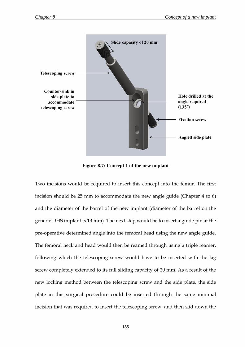
Chapter 8 Concept of a new implant
185
Figure 8.7: Concept 1 of the new implant
Two incisions would be required to insert this concept into the femur. The first
incision should be 25 mm to accommodate the new angle guide (Chapter 4 to 6)
and the diameter of the barrel of the new implant (diameter of the barrel on the
generic DHS implant is 13 mm). The next step would be to insert a guide pin at the
pre-operative determined angle into the femoral head using the new angle guide.
The femoral neck and head would then be reamed through using a triple reamer,
following which the telescoping screw would have to be inserted with the lag
screw completely extended to its full sliding capacity of 20 mm. As a result of the
new locking method between the telescoping screw and the side plate, the side
plate in this surgical procedure could be inserted through the same minimal
incision that was required to insert the telescoping screw, and then slid down the

Chapter 8 Concept of a new implant
186
lateral femur surface. A second incision would then be made to secure the side
plate with distal screws. The final surgical step would be to insert the fixation
screw to secure the telescoping screw to the side plate. The incision required for
the surgical procedure of this concept was less than 30 mm.
However, this concept had a problem because of the thin angled thread that was
drilled through the side plate for the telescoping screw. Although this was an
alternate solution for attaching the side plate to the lag screw, there was a very
high risk that stress concentration at the thread could lead to implant failure. At
the same time, although the system was not exactly the same, there are patents
published which use a fixation screw to attach the lag screw to the side plate
(Frigg, 1994; Shaw, 2007). Therefore, this idea was not taken forward to be selected
as the final concept for a new implant.
8. 5. 3. Concept 2
The second concept was a two part implant consisting of a telescoping screw and a
fixed angled side plate as seen in Figure 8.8. The telescoping screw was adapted
from concept 1, discussed in section 8.5.2. However, the bottom end of the barrel
has the screw threads on the outside. The telescoping screw allowed for a
maximum slide of 20 mm and the dimensions would be adapted from the generic
DHS lag screw and barrel. The side plate on the other hand was different to the
one discussed in concept 1. The side plate had an extrusion in the shape of a barrel

Chapter 8 Concept of a new implant
187
through which the telescoping screw would pass. The barrel had threads on the
inner surface, on which the telescoping screw would secure itself when it was
advanced through it into the femoral neck and head. Other distinctive features
included in the side plate were three distal locking screw holes and a tapered
bottom of the side plate. The advantages of the locking side plate were discussed
in section 8.4.7. The tapered bottom would make it easier for the side plate to slide
over the lateral femoral surface.
The implant would require a two incision approach for incision. The first incision
should be large enough to accommodate the angle guide and the diameter of the
barrel of the new implant (i.e. 25 mm). The second incision would be made to
insert the distal screws. This should be followed by inserting the guide pin into the
femoral neck and head using the new angle guide designed during this research
(Chapter 4 to 6). The next step would be to use a triple reamer and a tap (optional)
to create a tunnel for the telescoping screw and side plate. The side plate would
then be inserted through the incision, slid down the lateral femur surface and
secured in position using locking screws. The telescoping screw would be
advanced through the proximal incision into the femoral neck and head with its
sliding capacity fully extended till the threads of the telescoping screw and side
plate meet. The telescoping screw would then be turned until it would be secured
in position with the side plate. The concept would require two additional
instruments – i) a side plate inserter to assist in implanting the side plate on to the

Chapter 8 Concept of a new implant
188
femur and ii) a hexagonal screw driver to advance the telescoping screw fully
extended into the femoral neck and head.
Figure 8.8: (a) telescoping screw being advanced through a secured angled side plate;
(b) an assembled concept 2 of the new implant
Concept 2 did not present any immediate concerns and was able to fulfil all the
design specifications stated at the beginning of the Chapter. The concept was
taken forward for design verification, and is discussed further in Chapter 9.

Chapter 8 Concept of a new implant
189
8. 6. Summary
The summarising points of this chapter are listed below.
i. A new implant based on the principle of DHS implant, which would be
capable of being inserted through a maximum incision length of 30 mm
using a surgical technique similar to the one used for inserting the generic
DHS, was taken up for design.
ii. A PDS for the new implant was prepared in accordance with clauses stated
in the general requirements of surgical implants (BS EN ISO 14630, 2009),
particular requirements of implants for osteosynthesis (BS EN ISO 14602,
2010), and requirements of devices for the fixation of adult femur ends (BS
3531-15, 1992).
iii. Two concept ideas were generated based on the requirements laid in the
PDS. Concept 2, a two part implant, was selected to be taken through the
detail design stage, which is discussed in Chapter 9. The concept consisted
of a telescoping lag screw and an angled side plate.

Chapter 9 The new implant
190
9.1 Chapter at a glance
9. 1. 1. Chapter overview Figure 9.1 shows the chapter overview in the form of a flowchart.
Figure 9.1: Flowchart of the chapter structure
9. 1. 2. Keywords Fatigue test; finite element analysis; new implant; risk analysis; static loading
New implant
Risk Analysis
Design verification
Finite element Analysis
Prototype
Static loading Fatigue test
THE NEW IMPLANT

Chapter 9 The new implant
191
9. 2. Introduction
The concept for a new implant to treat fractures of the proximal femur was
selected in Chapter 8. The concept, based on the dynamic hip screw (DHS)
implant, incorporated the sliding mechanism. Furthermore, it would be possible to
implant this concept using a minimally invasive approach (surgical technique
described in Chapter 10). This chapter describes the new implant and its
components in detail.
The design of the new implant was verified using risk analysis, finite element
analysis and through mechanical tests conducted on manufactured prototype
samples to check for safety and effectiveness of the concept. The results of these
verifications are discussed in this chapter.
The dimensions used at first for the concept of the new implant (denoted as model
1) meant it was unable to withstand the loading conditions during the mechanical
tests as there was excessive bending of the angled side plate and fracture of
telescoping screw’s barrel (testing method described in section 9.7.2.3.). The
engineering drawings for model 1 are in Appendix B, along with pictures of the
ruptured barrel and the bent side plate. The dimensions (thickness of angled side
plate; and thickness of barrel) were reassessed, and the newer concept (model 2)
was used for detailed description and verification.

Chapter 9 The new implant
192
9. 3. New implant in detail
9. 3. 1. Implant overview
The new implant, a two component assembly consisting of an angled side plate
and a fixation screw as shown in Figure 9.2, was designed to treat fractures of the
proximal femur in adults. Unlike the lag screw in the generic DHS (section 8.4.6),
the fixation screw in the new implant is called a telescoping screw which included
a lag screw enclosed in a barrel with a closed end. The purpose of the telescoping
screw was to provide rotational stability to the fracture, and allow a restricted
slide (telescoping pipe mechanism) of the lag screw inside the barrel to enable
compression at the fracture site and promote bone-on-bone contact for faster
healing of the fracture. As determined in section 8.4.4., the maximum available
slide for the lag screw would be 20 mm; clearance of 1 mm between the lag screw
and inner surface of the barrel.
The implant would be manufactured using stainless steel 316L (ASTM F138,
Young’s modulus – 690 MPa, tensile strength – 860-1100 MPa, Poisson’s ratio –
0.33, values sourced from BS 5832-1, 2007; Ratner et al., 2004), which would also be
used to manufacture the new angle guide (discussed in Chapter 6). This material is
the most commonly used stainless steel for the manufacture of medical devices,
provides excellent resistance to corrosion, and is able to withstand sterilisation
using gamma radiation (Ratner et al., 2004; Harper, 2001). The new implant would

Chapter 9 The new implant
193
be able to fix fractures of femurs with neck/shaft angles in the range of 120
degrees to 150 degrees at 5 degree increments. A neck/shaft angle of 135 degrees
is most common (Canale, 2002); hence the corresponding 135º angled side plate is
used for description and analysis for the remainder of this chapter. The
dimensions of the new implant assembly as required by clause 5.1 of standard BS
3531-15 (1992) is shown in Figure 9.2, with values tabulated in Table 9.1. The
dimensions of the new implant were based on the existing DHS implant (section
8.4.9). The engineering drawings for the individual components of the assembly,
along with further details are discussed in their respective sections. The surgical
technique for the new implant is discussed in detail in Chapter 10.
Table 9.1: Dimensions of the new implant shown in Figure 9.2
No Dimension mm
1 Effective screw length 105
2 Thread length 21
3 Barrel length 40
4 Shaft diameter 9
5 Thread diameter 12.7
6 Barrel diameter 19
7 Effective plate length 65
8 Plate thickness Ranges from 6 at bottom to
10.5 at the top end

Chapter 9 The new implant
194
Figure 9.2: Nomenclature of dimensions of the new implant in accordance to
standard BS 3531-15 (1992)
9. 3. 2. Angled side plate
The new angled side plate, like the generic side plate in the DHS implant, was a
fixed angled plate with a large superior hole for the fixation screw (telescoping
screw for the new implant, and lag screw in the DHS implant), and distal holes to
secure the plate to the femoral shaft using screws. The engineering drawing of the

Chapter 9 The new implant
195
new angled side plate is shown in Figure 9.3. However, unlike the generic side
plate, the superior and the distal holes of the new angled plate were threaded. The
angled extrusion at the head of the side plate was a short cylinder with fine
threads (5/8-18 UNF 3B) on its inner surface to lock with the fine threads on the
surface of the barrel of the telescoping screw during implantation. The threaded
distal holes would allow locking screws to secure the plate onto the femoral
surface. The advantages of locking screws over conventional screws were
discussed in section 8.4.7.
The angle of the side plate was fixed between 120 degrees and 150 degrees at 5
degree increments to cater to the varying neck/ shaft angles of fractured femurs.
The inner surface of the plate, which interfaces with the femoral shaft surface, was
curved with a radius of 20 mm as the radius of curvature of the femur surface in
that region was determined to be between 13 to 18 mm in section 4.5.7. The
effective length of the angled side plate was fixed at 65 mm, and, like the PC.C.P.
implant (Orthofix srl, Italy – discussed in section 3.8.2.), it would only be available
with three distal holes as this number is considered to be adequate for fixation of
proximal femur fractures (section 8.4.4). The side plate exhibited an increasing
thickness ranging from 6 mm at the bottom end to 10.5 mm at the top, as shown in
Figure 9.3.

Chapter 9 The new implant
196
Figure 9.3: Engineering drawing of the angled side plate of the new implant

Chapter 9 The new implant
197
9. 3. 3. Telescoping screw
The telescoping screw of the new implant, a type C fixation screw (designed to be
inserted only after preparation of femoral neck and head – BS 3531-15, 1992), was
an assembly comprising of a lag screw of differing lengths enclosed in a barrel
with a closed end. The lag screw could be divided into a screw region and a
sliding region as shown in Figure 9.4. The screw region (length of 21 mm) would
be inserted into the femoral head for grip, and the sliding region would be able to
displace within the barrel to a maximum distance of 20 mm. The effective lengths
of telescoping screw available would range from 90 mm to 150 mm in increments
of 5 mm. Telescoping screws of lengths less than 90 mm were not possible as the
sliding region on the lag screw was too short to permit the 20 mm slide. Although
the PDS (section 3.9.3.3) stated lengths from 50 mm to 150 mm, successful
implants including the Gotfried PC.C.P. (section 3.8.2) only provide lengths from
90 mm to 110 mm. There have been no published concerns regarding the low
variability in lengths offered. A 105 mm telescoping screw was used for design
verification stages of this research (the engineering drawing shown in Figure 9.5.).
Figure 9.4: Regions of the telescoping screw of the new implant
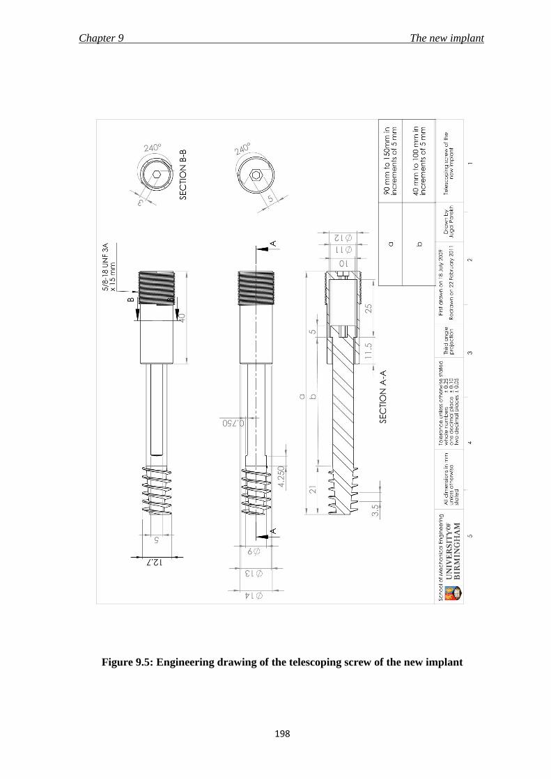
Chapter 9 The new implant
198
Figure 9.5: Engineering drawing of the telescoping screw of the new implant

Chapter 9 The new implant
199
Two opposing sides of the sliding region of the lag screw and the corresponding
inner surfaces of the barrel were flattened to provide rotational stability at the
fracture site. Hexagonal recesses were provided at the bottom of the lag screw and
the barrel to allow for insertion of the telescoping screw into the femur using a
telescoping screw inserter (section 10.4.5).
9. 4. Risk Analysis
Risk analysis, discussed in section 2.3.5.3 and conducted on the angle guide in
section 6.4., aimed to identify the hazards associated with the new implant and to
discuss control measures to eliminate or reduce the hazards. The methodology is
described in section 2.3.5.3 and the results are shown in Table 9.2. The analysis
should not be considered exhaustive and was conducted by the author following
literature review on the existing DHS implant failure presented in section 3.6.1,
and consultation with Prof. Maffulli (Consultant surgeon). The analysis only
included the telescoping screw and the angled side plate, and did not take into
consideration the packaging and manufacturing process of the product.
The hazards identified during the risk analysis of the new implant in Table 9.2
were addressed by effective control measures ensuring that the design is safe to
use. No major hazards were discovered during the analysis.

Chapter 9 The new implant
200
Table 9.2: Risk analysis of the new implant
Compo-
nent
Possible
hazard
or
failure
mode
Effect of
hazard or
failure
Cause of
hazard or
failure
O S D RPN Control
measure
Telescoping
screw
Cut-out
of the
femoral
head
Unsuccessful
treatment/
injury to
patient
Incorrect
placement
due to wrong
guide pin
insertion
5 6 6 180
To be used by
skilled surgeon
& image
intensifiers to
be used to
verify correct
placement of
guide pin
Insufficient
slide due to
jamming of
lag screw in
barrel
1 7 5 35
Clearance of 1
mm between
lag screw and
barrel was
provided
Wrong
length of
telescoping
screw
selected
1 3 7 21
Surgical
procedure
provided to
select correct
screw length
Fractured
fragments
displace
Excessive
slide of the
lag screw
3 6 6 108
Maximum
slide of lag
screw inside
barrel is
restricted to 20
mm
Fracture/
Breakage
Excessive
bending of
screw
1 10 5 50 Static bending
tests were
conducted to
check stiffness
of design Failure at
Barrel 1 10 5 50
Angled side
plate
Excessive
bending/
failure
Non-union of
fracture/
injury to
patient
Design is not
strong
enough
2 5 7 70
Static bending
tests were
conducted

Chapter 9 The new implant
201
Compo-
nent
Possible
hazard
or
failure
mode
Effect of
hazard or
failure
Cause of
hazard or
failure
O S D RPN Control
measure
Angled side
plate
Protrusio
n through
skin
Injury to
patient
Failure of
distal screws 2 10 2 40
Locking
screws were
provided to
enhance side
plate fixation
Breakage of
side plate 1 10 5 50
Static bending
tests were
conducted
Injury to
soft
tissue
during
insertion
Minor delay
to surgery/
patient
experiences
post-
operative
pain
Tapered
bottom edge
of the side
plate
1 7 8 56
Sufficient
incision and
cleaning of
operating site
Telescopi
ng screw
does not
fit into
the
superior
hole
Major delay
to surgery
Wear of
screw
threads on
telescoping
screw or side
plate
1 10 1 10
Should be
manufactured
well.
Threads
should be
checked prior
to surgery for
any defects

Chapter 9 The new implant
202
9. 5. Finite Element Analysis (FEA)
9. 5. 1. Overview
The principles of FEA were described in section 2.3.5.3., and the methodology was
discussed while conducting the analysis on the new angle guide in section 6.5. The
following sections discuss the FEA conducted on a three dimensional model of the
new implant, which was created using SolidWorks CAD software (3DS Daussalt
Systemes, Version 2008-2010, Lowell, MA, USA). The engineering drawings of the
individual components (telescoping screw and angled side plate) of the implant
assembly are shown in Figure 9.3 and 9.5. However, due to meshing errors
(models would not mesh successfully), three features of the models were removed
– namely the large threads at the head of the telescoping screw, the flattened sides
on the surfaces of the lag screw and the barrel, and the various fillets on the
model. Furthermore, the distal holes were replaced with a thin flat layer (thickness
of 0.5 mm) on the inner curved surface of the angled side plate. The layer was
used to restrict the model in all directions during the analysis as the plate will be
fixed against the femur with distal screws in that region. The details are further
discussed in section 9.5.2, and the FEA model is shown in Figure 9.6a. The static
analysis on the model was conducted using the integrated FEA tool called
SolidWorks Simulation (COSMOS in version 2008).

Chapter 9 The new implant
203
The FEA was also conducted on a three-dimensional model of the generic DHS
implant. The dimensions of the model were taken from the 135 degrees DHS
implant with three holes side plate (catalogue no. 12-4126) and 105 mm lag screw
(catalogue no. 12-1110) manufactured by Smith & Nephew plc. (London, UK), and
their engineering drawings are shown in Figures 9.6 and 9.7. The results of FEA
studies on the new implant and the DHS implant were compared to verify the
feasibility of the new design.
9. 5. 2. Pre-processing
The three dimensional models of the generic DHS and the new implant were
assigned with material properties of stainless steel 316L. ASTM F 384 (2006), a
standard discussing the test methods for metallic angled orthopaedic fracture
fixation device, was used as a guide for specification of loading conditions on the
models. According to the standard, the side plate of the implant has to be rigidly
attached to a fully constrained body with the distal screws, and the load has to be
applied at a point which equals to 80 % of the length of the fixation screw (84 mm
for a 105 mm long fixation screw). However, the direction of load applied was not
parallel to the long axis of the side plate as suggested by the standard, but was
applied perpendicular to the long axis of the fixation screw. The modification to
the configuration was made as this setup would prevent damage to the load cell of
the testing machine due to reaction forces generated in other axis due to probable
slide of the telescoping screw during mechanical tests conducted on the prototype

Chapter 9 The new implant
204
Figure 9.6: Engineering drawing of the angled side plate of the generic DHS implant

Chapter 9 The new implant
205
Figure 9.7: Engineering drawing of the lag screw of the generic DHS implant

Chapter 9 The new implant
206
(section 9.7). Secondly, the configuration was also used by Zirn (2008) to analyse
the load capacity of their newly designed hip compression screw device. This was
the only study discovered which had published the results of static load and
fatigue testing conducted on a DHS and a similar implant. Hence, it allowed for
comparison of results during the mechanical tests (section 9.7). The loading
conditions during the FEA were kept similar to maintain consistency of testing
method and configuration during this research.
Figure 9.8: Three dimensional models of a) the new implant, and b) the generic DHS
implant, meshed at size of 1.75 mm. The loading and fixtures of the models were
specified as discussed in section 9.5.2.
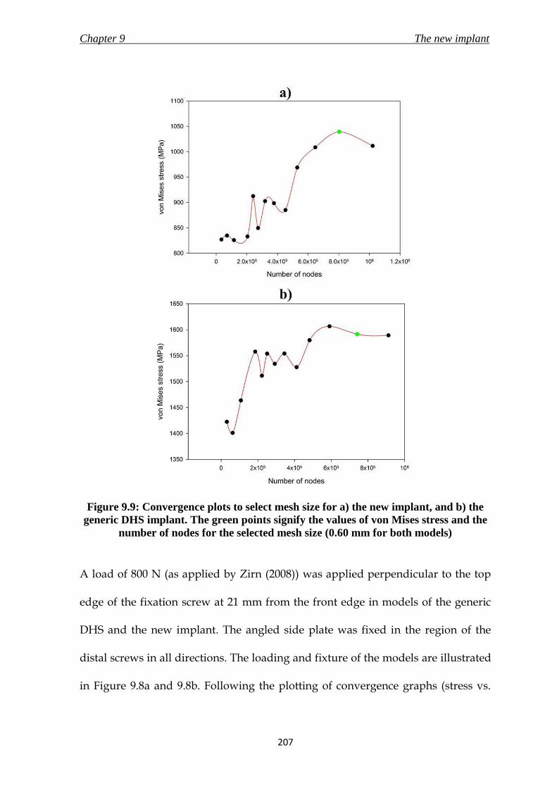
Chapter 9 The new implant
207
Figure 9.9: Convergence plots to select mesh size for a) the new implant, and b) the
generic DHS implant. The green points signify the values of von Mises stress and the
number of nodes for the selected mesh size (0.60 mm for both models)
A load of 800 N (as applied by Zirn (2008)) was applied perpendicular to the top
edge of the fixation screw at 21 mm from the front edge in models of the generic
DHS and the new implant. The angled side plate was fixed in the region of the
distal screws in all directions. The loading and fixture of the models are illustrated
in Figure 9.8a and 9.8b. Following the plotting of convergence graphs (stress vs.

Chapter 9 The new implant
208
number of nodes), shown in Figure 9.9a-b, for the respective implant models, the
mesh size selected were: 0.60 mm (number of elements - 554833; number of nodes
- 802755) for the model of the new implant and 0.60 mm (number of elements -
515412; number of nodes - 742004) for the model of the generic DHS.
9. 5. 3. Post-processing
Graphical representations of the deformed model, along with the values of the
solutions were generated, and are shown in Figure 9.10. The displacement of the
model in units of mm, and von Mises stresses on the model in units of MPa, were
presented at the end of the analysis as results.
The maximum stress in the new implant model was found on the angled side plate
at the angled bend as shown in Figure 9.10a to have a value of 1039 MPa. The
maximum displacement was 2.4 mm, at the front of the fixation screw. Similarly,
on the generic DHS implant, the highest stress of 1591 MPa (Figure 9.10b) was on
the angled bend on the angled side plate; with the maximum displacement of 3.6
mm at the front of the fixation screw.
The values of stresses and displacement on the new implant were less than in the
generic DHS implant, which is already being used in the market as a successful
device for proximal femur fracture treatment. The value of the maximum stress in
the new implant was also less compared to the maximum tensile strength of the

Chapter 9 The new implant
209
material (1100 MPa). Therefore, this design was concluded to pass the verification
using FEA.
Figure 9.10: Graphical representation of von Mises stress generated on a) the new
implant, and b) the generic DHS implant, due to a load of 800 N during the FEA

Chapter 9 The new implant
210
9. 6 Prototype manufacture
9. 6. 1. Overview
Prototypes of the new implant were prepared to conduct mechanical testing to
analyse the effect of static and fatigue (cyclic) loading on the design. However, a
perfect physical reproduction of the computer generated design would require an
expensive mould to be manufactured, and therefore minor modifications were
made to the actual design for ease of manufacture in a basic machining workshop.
Care was taken to minimise the effect of changes on performance and strength of
the design, and it was verified by conducting FEA to compare the values of
stresses and displacement in the modified and the actual design of the new
implant.
The changes in the manufactured model, as shown in Figure 9.11, included the
removal of large threads at the head of telescoping screw, removal of flattened
sides on the surfaces of lag screw and barrel, replacement of curved thickness
increase of the angled side plate with stepped increase, replacement of curved
inner surface of angled side plate with a flat surface, the angled circular extrusion
at the top of the angled side plate was not chamfered or filleted, the angled
circular extrusion on the angled side plate was not threaded through due to which
the telescoping screw was to be screwed on from the front end, removal of tapered
bottom of the angled side plate, and finally the fine threads on outer surface of the
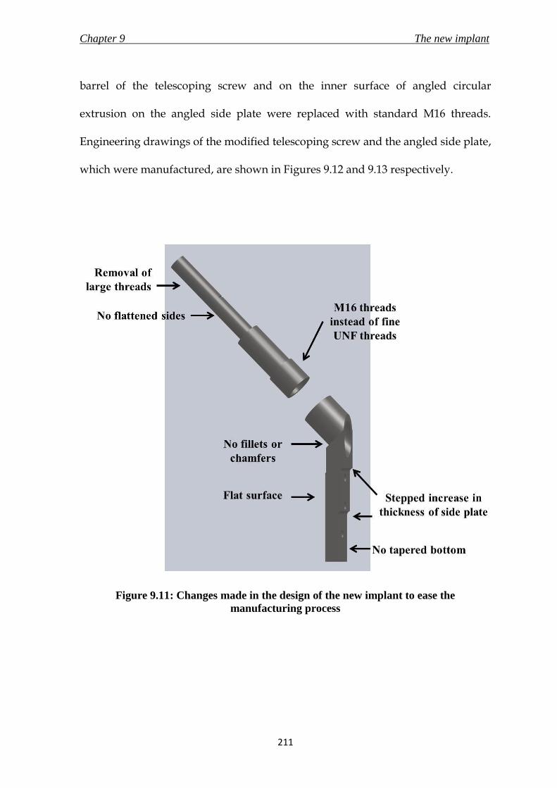
Chapter 9 The new implant
211
barrel of the telescoping screw and on the inner surface of angled circular
extrusion on the angled side plate were replaced with standard M16 threads.
Engineering drawings of the modified telescoping screw and the angled side plate,
which were manufactured, are shown in Figures 9.12 and 9.13 respectively.
Figure 9.11: Changes made in the design of the new implant to ease the
manufacturing process

Chapter 9 The new implant
212
Figure 9.12: Engineering drawing of the modified angled side plate of the new
implant for manufacture

Chapter 9 The new implant
213
Figure 9.13: Engineering drawing of the modified telescoping screw of the new
implant for manufacture

Chapter 9 The new implant
214
9. 6. 2. FEA of prototype
The three dimensional stainless steel 316L model of the prototype was loaded with
800 N of downward axial force acting on the top edge at 21 mm from the front
edge of the telescoping screw. Similar to the FEA conducted on the actual design
of the new implant in section 9.5, the prototype model was restrained at the
angled side plate. The mesh size selected for the model after plotting of a
convergence graph was 0.60 mm (number of elements - 513629; number of nodes -
748641). The maximum value of von Mises stress on the model was 1018 MPa, and
was recorded at the angled bend on the angled side plate. The maximum
displacement calculated was 2.31 mm at the front of the telescoping screw. These
values were very close to the results of FEA on the new implant three dimensional
model that is discussed in section 9.5.4.
9. 6. 3 The manufactured prototype
Four prototypes of the new implant made of stainless steel 316L were
manufactured by Mr Bryan Jarvis of Truturn Precision Engineering ltd. (Stroud,
Gloucestershire, UK). The assembly was supplied in three parts – the angled side
plate, the barrel and the lag screw. The angled side plate was manufactured out of
a single block of stainless steel. The dimensions of the delivered samples were
verified for consistency to the supplied engineering drawings.
Chapter 9 The new implant
215
9. 7. Mechanical testing
9. 7. 1. Investigation objective
As previously stated, the new implant would be used to treat fractures of the
proximal femur. Therefore, the design would have to withstand multiple cycles of
compression loading at the site for the duration of the healing process until the
bone is able to provide mechanical support to reduce the stresses in the implant.
The purpose of this study was to analyse the load capacity of the new implant
subjected to a) single cycle compression bending load to measure the displacement
response of the design, and b) constant frequency sinusoidal cyclic bending
moment waveform load to determine the cycles to failure of the new implant
(fatigue test). ASTM F-384 (2006), which describes the specifications and test
methods for metallic angled orthopaedic fracture fixation devices, was used as a
guide for the setup of the testing configuration.
The Dynamic Martin Screw (DMS) was first implanted in 1992, and has since been
used to treat more than 50000 patients (Dittel and Rapp, 2008). The implant utilises
the sliding lag screw principle with an adjustable angle side plate. The tests
conducted on the DMS by Zirn (2008) were the only published material found by
the author that measured and recorded the loading capacity values from static and
cyclic bending load test, as directed by ASTM F-384. The study conducted by Zirn
Chapter 9 The new implant
216
concluded that the DMS out-performed the 135 degrees DHS-plate implant in the
static bending load test, and the results for the cyclic tests were within the range of
values measured on the DHS-plate implant. The results of mechanical tests
conducted on the new implant were compared to those of the DMS to verify the
loading capacity of the new design.
9. 7. 2. Materials and method
9. 7. 2. 1. New implant samples
Four samples of the modified version of the new implant were manufactured for
the mechanical tests. The details of the manufactured design were discussed in
section 9.6. Three samples were used for the static loading tests, and one for the
fatigue test. The new implant assembly was put together by first inserting the lag
screw into the barrel to complete the telescoping screw assembly, followed by
screwing the telescoping screw into the angled side plate.
9. 7. 2. 2. Test rig
A custom rig (Figure 9.14), manufactured with stainless steel 316, was designed
for fixation to a Bose ELF 3300 testing machine (Bose Corporation, ElectroForce
Systems Group, Minnesota, USA) to conduct both the mechanical tests on the
prototypes discussed in this section. The rig was manufactured by Mr Bryan Jarvis
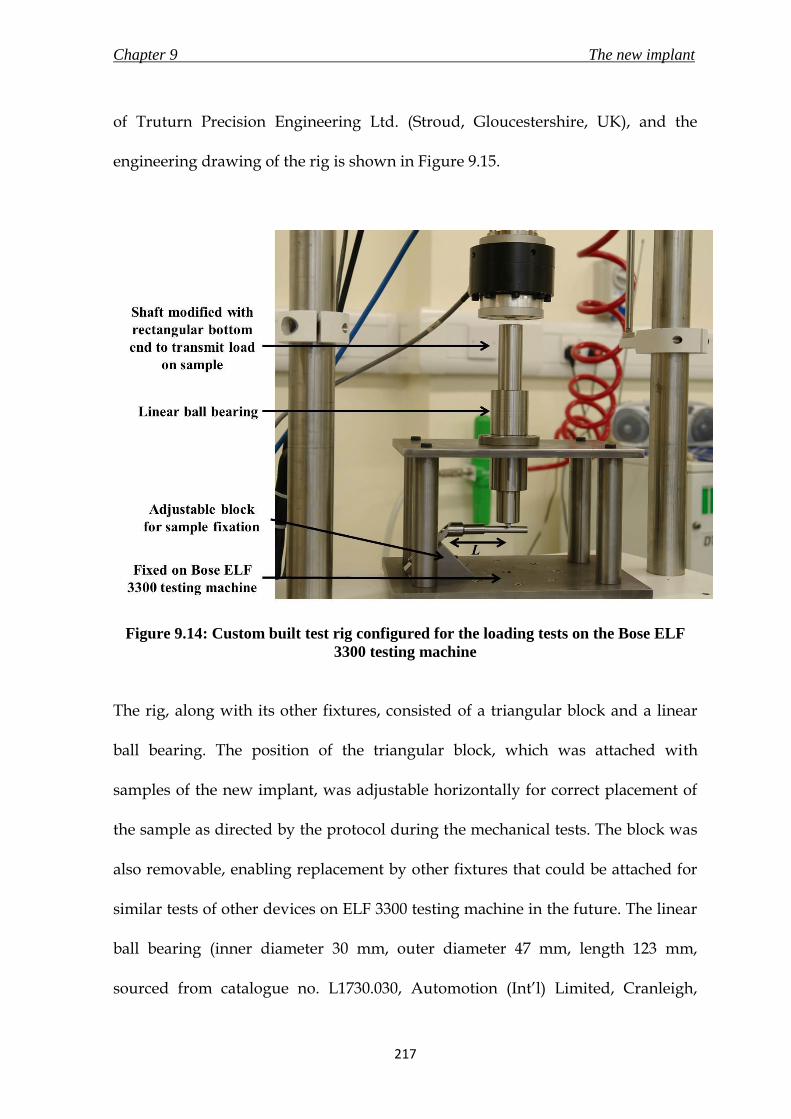
Chapter 9 The new implant
217
of Truturn Precision Engineering Ltd. (Stroud, Gloucestershire, UK), and the
engineering drawing of the rig is shown in Figure 9.15.
Figure 9.14: Custom built test rig configured for the loading tests on the Bose ELF
3300 testing machine
The rig, along with its other fixtures, consisted of a triangular block and a linear
ball bearing. The position of the triangular block, which was attached with
samples of the new implant, was adjustable horizontally for correct placement of
the sample as directed by the protocol during the mechanical tests. The block was
also removable, enabling replacement by other fixtures that could be attached for
similar tests of other devices on ELF 3300 testing machine in the future. The linear
ball bearing (inner diameter 30 mm, outer diameter 47 mm, length 123 mm,
sourced from catalogue no. L1730.030, Automotion (Int’l) Limited, Cranleigh,

Chapter 9 The new implant
218
Surrey, UK) and the accompanying cylindrical shaft (hardened stainless steel 316,
diameter 30 mm, length 350 mm, sourced from catalogue no. SSS-30M-350,
Automotion (Int’l) Limited, Cranleigh, Surrey, UK) were attached at the top of the
rig to allow only axial transmission of the compressive load from the ELF 3300
testing machine onto the samples. This linear bearing was used to prevent damage
to the testing machine’s load cell due to forces generated in other directions
during the bending tests. The bottom surface of the shaft was modified to form a
rectangular surface (5 mm × 25 mm) at the centre, which would be placed on top
of the lag screw during the bending tests.
9. 7. 2. 3. Static loading test
9. 7. 2. 3. 1. Test setup
The configuration used during the static loading test is illustrated in Figure 9.14.
The Bose ELF 3300 testing machine, operated under the control of WinTest
software was used to supply the compressive bending load during the test. The
machine is equipped with a load cell of full scale of 4500 N, and displacement
transducer with a full scale of 25 mm. The test rig discussed in section 9.7.2.2 was
fixed onto the testing machine. The compressive force from the machine was
transmitted to the sample through the cylindrical shaft placed inside the linear
bearing on the test rig. The new implant sample was secured onto the triangular
block on the testing rig using three M5 screws. The block was adjusted

Chapter 9 The new implant
219
horizontally to ensure that the cylindrical shaft atop the lag screw was placed to
allow for a lever arm, L (distance from top point of triangular block to the point of
loading on the new implant), of 80 % of the length of the telescoping screw (84 mm
for 105 mm long telescoping screw, as directed by ASTM F-384). The load was
applied perpendicularly to the long axis of the lag screw rather than parallel to the
long axis of the angled side plate, as suggested by ASTM F-384, due to the reasons
discussed in section 9.5.2.
The testing machine was operated in displacement control (0.17 mm/s for a total
displacement of 16 mm – displacement restricted due to test rig setup and
machine’s limited stroke of 25 mm) and the force was recorded at a rate of 200
data points per second. The procedure was to measure the compressive load
required to bend the implant, which was used to generate a load versus
displacement diagram. The test was deemed to have ended on reaching a
maximum displacement of 16 mm or due to failure of the sample. The test was
repeated three times with a fresh sample of the new implant for every run.
9. 7. 2. 3. 2. Data Analysis
A graph of load against displacement was plotted for all the three samples. The
corresponding displacement, M, at a load of 784.8 N (80.0 kg) was recorded.

Chapter 9 The new implant
220
Figure 9.15: Engineering of the test rig used for the mechanical tests discussed in this
section

Chapter 9 The new implant
221
9. 7. 2. 4. Fatigue test
The test configuration for the fatigue test was the same as the setup described for
the static loading test in section 9.7.2.3.1 and shown in Figure 9.14. A sinusoidal
load was applied with frequency of 5 Hz up till failure under load control. The
maximum loads experienced were determined by a load ratio, R, of upper load to
lower load of 0.01 (ASTM F-384), with upper load of 800 N (Zirn, 2008). The test
was considered to have ended either on failure of implant or on reaching one
million cycles (ASTM F-384).
9. 7. 3. Results
9. 7. 3. 1. Static loading test
All the three samples completed the displacement of 16 mm without failures. A
graph of applied load was plotted against displacement, as shown in Figure 9.16.
The average displacement recorded at the application of 784.8 N of load in the
three samples was 4.7 ± 1.5 mm. The values are tabulated in Table 9.3.
Table 9.3: Values of displacement, in mm, of samples of the new implant at loading of
784.8 N
Sample 1 Sample 2 Sample 3
Displacement (mm) 6.5 4.1 3.7

Chapter 9 The new implant
222
Figure 9.16: Graph of applied load, in N, versus displacement, in mm, realised in the
new implant during the static loading test of sample 1 (green), 2 (blue), and 3 (red).
The vertical lines from x-axis represent the bending in mm of the respective new
implant sample when applied with a load of 784.8 N (80 kg). The bending values are
tabulated in Table 9.3
9. 7. 3. 2. Fatigue test
The new implant failed after 86267 cycles of loading between 80 N and 800 N at a
frequency of 5 Hz. The cause of the failure was a fracture at the threads on the
outer surface of the barrel of the telescoping screw. The fractured prototype is
shown in Figure 9.17.
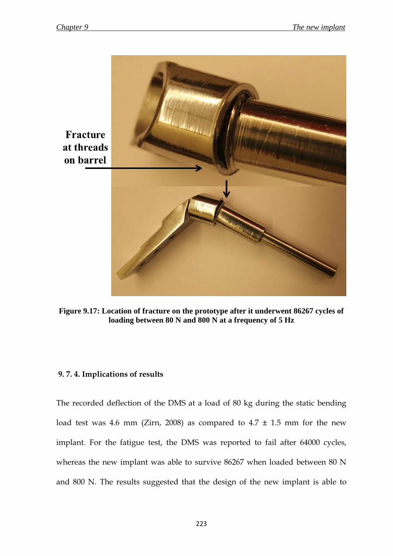
Chapter 9 The new implant
223
Figure 9.17: Location of fracture on the prototype after it underwent 86267 cycles of
loading between 80 N and 800 N at a frequency of 5 Hz
9. 7. 4. Implications of results
The recorded deflection of the DMS at a load of 80 kg during the static bending
load test was 4.6 mm (Zirn, 2008) as compared to 4.7 ± 1.5 mm for the new
implant. For the fatigue test, the DMS was reported to fail after 64000 cycles,
whereas the new implant was able to survive 86267 when loaded between 80 N
and 800 N. The results suggested that the design of the new implant is able to

Chapter 9 The new implant
224
withstand static and cyclic bending loading condition required of an implant for
treatment of proximal femur fractures. The samples of the implant were
manufactured using tools available in a normal workshop, and hence were not
produced to the standard of a medical implant. This caused variability in the static
loading results. However, considering the results were still within the values
mentioned in the literature, prototypes manufactured with the appropriate
machinery to the exact specification should produce better results.
9. 8. The new implant
The design of the new implant, described in section 9.3, successfully underwent
thorough verification procedures in the form of risk analysis, finite element
analysis and mechanical testing of manufactured prototype. The new implant,
along with its associated instruments is presented in Chapter 10 for the
description of surgical technique. The new implant fulfilled all the requirements
that were stated in the product design specification stage in Chapter 8.

Chapter 9 The new implant
225
9. 9. Summary
The summarising points of the chapter are listed below.
i. The new implant, made of stainless steel 316L, was designed for treatment
of proximal femur fractures. The assembly comprised of a telescoping
screw and an angled side plate. A minimally invasive approach would be
utilised to surgically implant the new device. The design was verified using
risk analysis, FEA and mechanical testing.
ii. The hazards identified during the risk analysis of the new implant were
addressed with suitable control measures to minimise/ avoid the risk.
iii. The results of the new implant during FEA showed that the design would
undergo smaller displacement and would generate less stress than the
generic DHS implant when subjected with a compressive load of 800 N. The
mechanical tests conducted on the new implant also concluded that the
deflection of 4.7 ± 1.5 mm during application of compressive bending load
of 80 kg (784.8 N), and 86267 cycles to failure during fatigue tests was better
and within range of the values generated by the generic 135º DHS-plate
implant respectively.
Chapter 10 Operative technique for the new implant
226
10.1 Chapter at a glance
10. 1. 1. Chapter overview Figure 10.1 shows the chapter overview in the form of a flowchart.
Figure 10.1: Flowchart of the chapter structure
10. 1. 2. Keywords Minimally invasive surgery; operative technique
The new implant
Operative technique
Instruments for a minimally
invasive surgery
OPERATIVE TECHNIQUE FOR
THE NEW IMPLANT

Chapter 10 Operative technique for the new implant
227
10. 2. Introduction
Operative technique manuals are published by all leading orthopaedic device
manufacturers to let the surgeon know the method of implantation and also to
promote their products. Some examples include the application and technique
information for the TK2 compression hip screw system by DePuy Orthopaedics
(Warsaw, Indiana, USA) and the surgical technique for compression hip screw
plates and nails by Smith & Nephew plc. (London, UK). The purpose of this
chapter is to present the new medical devices designed during the course of this
research, and highlight their features and attributes. Although the new
instruments developed (new angle guide and ergonomic T-handle) in the research
could be used for the dynamic hip screw (DHS) implant surgery by simply
replacing the conventional instruments, they also form an integral part of the
surgical procedure for the new implant. This chapter describes the surgical
procedure to be used for fixing the new implant on a fractured femur using a
minimally invasive approach. The layout of sections 10.3. to 10.5. in this chapter
attempts to present the information required for a corporate brochure for an
orthopaedic implant in the format required of a PhD thesis. Hence, instead of
using conventional referencing system, statements are cross-referenced to the
appropriate part of the thesis where justification is provided. The operative
technique for the generic DHS was discussed in section 3.8.3. The three
dimensional models of medical devices shown in this chapter were drawn using
SolidWorks CAD software (2010, 3DS Daussalt Systemes, MA, USA).

Chapter 10 Operative technique for the new implant
228
10. 3. The new implant
10. 3. 1. Overview
The new implant was a two part assembly consisting of an angled side plate and a
telescoping screw; both made of stainless steel 316L (section 9.3.1). The implant
was designed to treat fractures of the proximal femur. The three fundamental
principles of the new implant were to –
a. evolve the established and popular dynamic hip screw (DHS) implant to
allow easy insertion and implantation through an incision of less than 30
mm;
b. utilise the principle of sliding the lag screw into the side plate to promote
bone-on-bone contact for faster healing and weight bearing;
c. provide a comfortable and confident experience to the surgeons by
applying similar instruments and surgical procedure steps, as the generic
DHS, to insert the new implant.
10. 3. 2. Angled side plate
The angled side plate of the new implant, as shown in Figure 10.2, consisted of a
plate with three distal locking screw holes; and was proximally attached to a short
angled, threaded cylinder. The cylinder/ plate angle was fixed at 120, 130, 135,
140, 145 or 150 degrees; the angle required would be selected by the surgeon based

Chapter 10 Operative technique for the new implant
229
on the neck/shaft angle of the patients’ fractured femur before surgery. While
inserting the plate, the angled cylinder would be connected to a side plate
introducer (section 10 .4. 4), and the bottom end would slide down the lateral
femur surface. The inner surface of the side plate was curved with a radius of 20
mm to complement the lateral femur surface and the tapered bottom edge would
aid in sliding through the tissues on the femoral surface (section 9.3.2). The three
distal holes would secure the plate to the femur with 5.00 mm diameter locking
screws to enhance stability and fixation of the implant on the fractured bone.
Figure 10.2: The new angled side plate

Chapter 10 Operative technique for the new implant
230
10. 3. 3. Telescoping screw
The telescoping screw was a two-part system consisting of a lag screw, enclosed in
a barrel, with a closed end and a maximum slide capacity of 20 mm (section 9.3.3).
The different features of the device are illustrated in Figure 10.3a-c. The available
lengths of the telescoping screw would range from 90 mm to 140 mm in 10 mm
increments. The threads at the bottom end of the barrel screw into the angled side
plate, and the large threads at the head of the lag screw would be advanced
through the femoral neck into the head for fixation. The hexagonal recesses in the
lag screw and the barrel would allow the lag screw inserter to advance the
telescoping screw, fully extended (with the 20 mm slide), into the femur.
Figure 10.3: Telescoping screw – a) fully extended, b) after maximum slide of 20 mm,
and c) cross section view

Chapter 10 Operative technique for the new implant
231
10. 3. 4. Potential features and benefits
The foremost advantage of the new implant would be that it was designed for
minimally invasive surgery (MIS), and at the same time included the features of
the popular DHS implant. The advantages of MIS were discussed in detail in
section 3.7. The inclusion of the locking side plate for enhanced implant stability
(section 8.4.7), and telescoping screws which avoid excessive slide of the lag screw
(section 8.4.6) were incorporated in the new implant to overcome the causes of
implant failures that were reported in the generic DHS (3.6.1). The surgeons
would encounter a gentler learning curve due to a similarity of the new surgical
technique to the conventional DHS operative technique. The new instruments also
added ergonomic features to their design to ensure a comfortable experience for
the surgeon. The surgical procedure for this implant would require only two
additional instruments to those already in use for the generic DHS implant and
hence would not provide an additional burden on the hospital inventory.

Chapter 10 Operative technique for the new implant
232
10. 4. Instruments for a minimally invasive surgery
10. 4. 1. Overview
This section discusses the instruments that will be required for the surgical
procedure for the new implant. The instrument set for the new implant would
include two additional instruments – a side plate inserter (section 10.4.4), and a
telescoping screw inserter (section 10.4.5), in addition to the generic DHS
implant’s instrument set. A new angle guide (Chapter 4-6) and an ergonomic T-
handle (Chapter 7) were designed to aid in the minimally invasive approach. The
instruments were designed to withstand steam sterilisation or sterilisation with
irradiation to cater to the differing needs of a re-use and single-use market
respectively.
10. 4. 2. An ergonomic T-handle
The ergonomic T-handle, shown in Figure 10.4 and discussed in detail in Chapter
7, was designed to provide a comfortable interface to the surgeon to hold, grip and
use the various instruments whilst bringing about minimum tiredness during a
minimally invasive surgery. The shape and dimensions of the handle would allow
surgeons of differing hand sizes and either handedness to use it comfortably. The
combination of circular and rectangular cross section of the handle would provide
comfort and grasping purchase to the surgeon. The design of the T-handle was

Chapter 10 Operative technique for the new implant
233
optimised to provide the surgeon with a grip enabling him/ her to transfer
required torque at the same time as exhibiting control and flexibility of the
instrument. The stainless steel 316L skeleton would be molded with
polypropylene to give the desired shape, and overmolded with thermoplastic
polyolefin (TPO) elastomer to provide the surgeon with a soft and comfortable
touch (section 7.8.2). The soft touch TPO elastomer would be colour coded to
correspond to different stages of the surgical procedure to allow for easy
identification of instruments during the surgery. The colour coding is stated in
section 10.5.
Figure 10.4: Colour coded ergonomic T-handles

Chapter 10 Operative technique for the new implant
234
10. 4. 3. New angle guide
The new angle guide (Figure 10.5) combined the familiarity of the generic angle
guide, used in the “gold standard” DHS surgery, with ergonomic features for use
in minimally invasive surgery. The new base replaced the sharp prongs with a
curved profile made of biocompatible and mouldable silicone elastomer (Silastic
Q7-4780, Dow Corning Ltd, Coventry, UK) for improved stability on the uneven
and curved lateral femur surface; and stainless steel surface roughened using
spark erosion for enhanced grip (Chapter 5; section 6.3.3). The guide pin exit-hole
at the bottom of the base plate was placed 20 mm from the front edge of the base
to guide the surgeon to correctly place the angle guide on the femur, as the guide
pin insertion point is 20 mm below the vastus lateralis ridge (shown in Figure 10.9a;
details in section 6.3.2).
Figure 10.5: The new angle guide

Chapter 10 Operative technique for the new implant
235
10. 4. 4. Side plate inserter
The side plate inserter, shown in Figure 10.6, would consist of a stainless steel
316L rod (diameter of 10 mm, length 150 mm) connected at an angle to a cylinder
of two different diameters at one end, and to the T-handle (section 10.4.2) at the
other end. The rod/ cylinder angle would correspond to the angle of the side plate
to be used during surgery. The head of the introducer, which would have two
diameters to correspond to the threaded (diameter of 13.75 mm, length 15 mm)
and unthreaded parts (diameter of 15.75 mm, length 20 mm) of the proximal hole
of the side plate, would fit inside the side plate hole. The side plate would then be
manoeuvred into position on the patient’s femur for fixation. The engineering
drawing of this instrument is shown in Appendix C.
Figure 10.6: Side plate inserter

Chapter 10 Operative technique for the new implant
236
10. 4. 5. Telescoping screw inserter
The telescoping screw inserter would consist of a stainless steel 316L hexagonal
rod (length 176.5 mm), of two diameters, connected to an ergonomic T-handle
(Figure 10.7). The hexagonal rod with the smaller diameter (3 mm) would
correspond to the hexagonal recess in the lag screw; the larger diameter rod (5
mm) would correspond to the recess in the barrel of the telescoping screw. The
purpose of this instrument was to advance a fully extended (20 mm) telescoping
screw into the femoral head, and screw it into the secured side plate. The
engineering drawing for this instrument is shown in Appendix C.
Figure 10.7: Telescoping screw inserter

Chapter 10 Operative technique for the new implant
237
10. 4. 6. Other instruments
The other instruments, shown in Figure 10.8a-d, would include (a) a 2.5 mm
diameter guide pin, (b) a depth gauge, (c) a triple reamer, (d) a tap, and a soft-
tissue retractor (not shown). The instruments and their design would remain the
same as the ones used during the current DHS implant surgery (section 3.6.3.1).
However, the dimensions on the triple reamer and the tap would be modified to
suit the new implant if the new implant were to be manufactured. Also, the
generic T-handles of these instruments would be replaced with colour coded
ergonomic T-handles discussed in section 10. 4. 2.
Figure 10.8: The other instruments to be used during the surgical procedure include:
a) 2.5 mm guide pin, b) depth gauge, c) triple reamer, and d) tap. The instruments
shown are manufactured by Sushrut Surgical Pvt. Ltd. (Pune, Maharashtra, India)
for the generic DHS implant surgery.

Chapter 10 Operative technique for the new implant
238
10. 5. Operative technique
10. 5. 1. Overview
This section discusses the surgical procedure required to insert and secure the new
implant on to the femur. The procedure is divided into four colour coded stages.
The unique colour for each stage is mentioned in the headings below. The chosen
fractured femoral neck/shaft angle was 135 degrees, and hence a 135 degrees
angled side plate and corresponding angle guide shall be used in the technique
described. The surgical procedure was reviewed by Prof. Maffulli; it should be
noted that the operative technique does not include pre-operative planning and
post-operative care details. The technique assumed that the patient is already
placed in a supine position on the operating table and is prepared for implantation
following anatomical reduction of the fracture.
10. 5. 2. Guide pin placement (Green)
The vastus lateralis ridge is regarded as an important landmark throughout this
surgical approach. The incision start point would be located approximately 30 mm
below this landmark. An approach to the lateral side of the proximal femur would
be made with a straight incision of 30 mm extending distally as shown in Figure
10.9a. The guide pin in the figures is red for illustration purposes only.
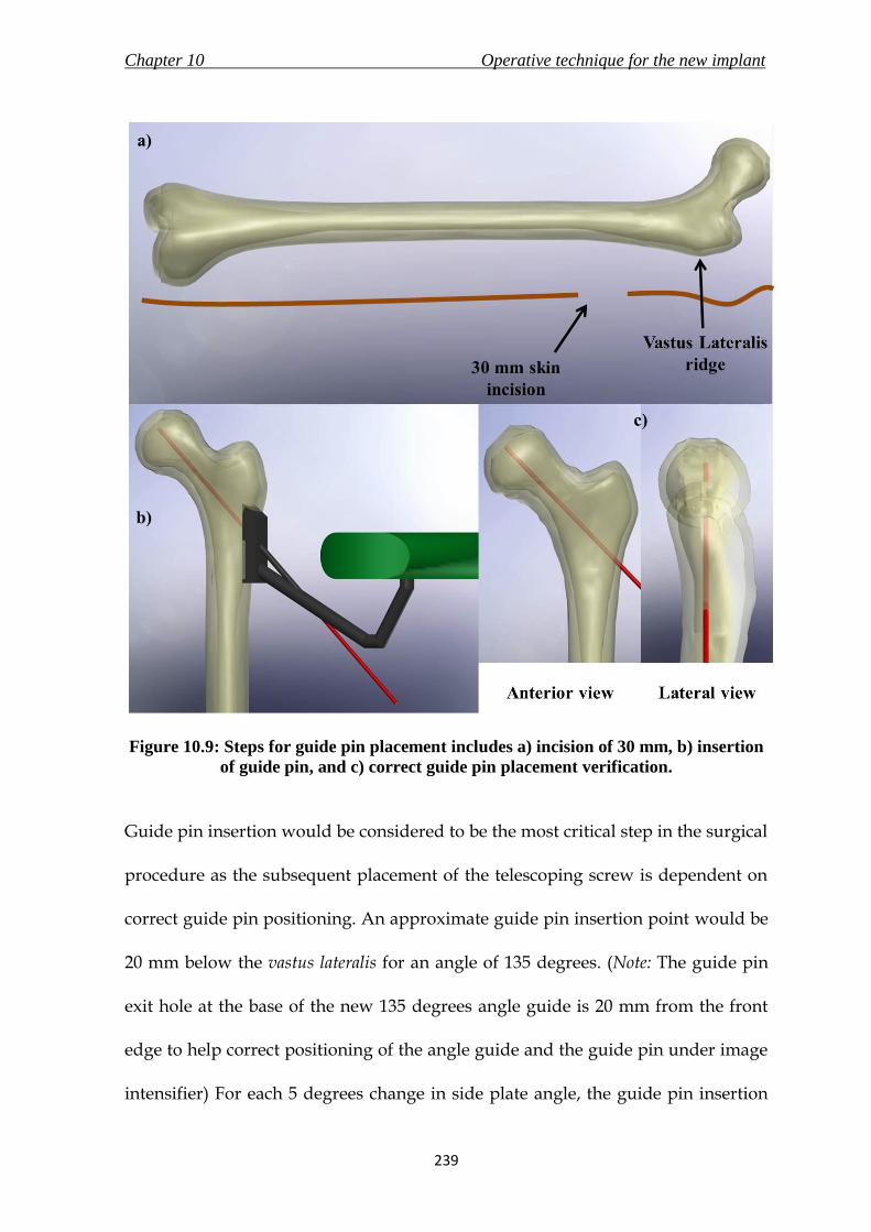
Chapter 10 Operative technique for the new implant
239
Figure 10.9: Steps for guide pin placement includes a) incision of 30 mm, b) insertion
of guide pin, and c) correct guide pin placement verification.
Guide pin insertion would be considered to be the most critical step in the surgical
procedure as the subsequent placement of the telescoping screw is dependent on
correct guide pin positioning. An approximate guide pin insertion point would be
20 mm below the vastus lateralis for an angle of 135 degrees. (Note: The guide pin
exit hole at the base of the new 135 degrees angle guide is 20 mm from the front
edge to help correct positioning of the angle guide and the guide pin under image
intensifier) For each 5 degrees change in side plate angle, the guide pin insertion

Chapter 10 Operative technique for the new implant
240
point would shift approximately 5 mm distally or proximally for increased or
decreased angle, respectively.
The new angle guide would be held firmly on the lateral femoral shaft, and the 2.5
mm guide pin would be advanced through the hole in the angle guide into the
femoral head (Figure 10.9b) until it reaches the centre of the femoral head, as
shown in both anterior and lateral view in Figure 10.9c.
10. 5. 3. Reaming and tapping (Yellow)
After the guide pin is placed in a satisfactory position, the depth gauge would
slide over the guide pin to measure the length of pin in bone. The reaming depth
and the telescoping screw length selected would be 10 mm shorter than the depth
gauge reading. (For example, if depth gauge reading = 110 mm; reaming depth =
lag screw length = 100 mm)
A tunnel of three diameters corresponding to the three different diameters of the
lag screw (diameter of 9 mm), barrel (diameter of 14 mm) and side plate cylinder
(diameter of 19 mm) would have to be made using the triple reamer over the
guide pin, as shown in Figure 10.10. Following the reaming, the femoral head and
neck would be tapped (outside thread diameter – 12.7 mm). This would be an
optional step, particularly important only in dense bone. The tapping depth would
be the same as the reaming depth.

Chapter 10 Operative technique for the new implant
241
Figure 10.10: Reaming of the femur using a triple reamer over the guide pin.
10. 5. 4. Side plate fixation (Orange)
The guide wire would have to be removed and then reinserted at the end of this
stage. The steps in this stage are illustrated in Figure 10.11a-c. The side plate
inserter would be placed inside the proximal hole of the angled side plate (a),
which would then be introduced into the patient’s body with the bottom end of
the side plate advanced first through the incision, following which it would slide
down the femoral shaft into position (b). The skin and soft tissues would then be
pulled back with the aid of a soft-tissue retractor, following which the side plate

Chapter 10 Operative technique for the new implant
242
would be secured onto the femoral shaft with the insertion of distal locking
screws. The side plate inserter would be pulled out of the side plate proximal hole
after the distal holes are locked onto the femoral shaft with screws (c).
Figure 10.11: Steps for side plate fixation include – a) placing the side plate inserter
inside the angled side plate, b) sliding the side plate bottom end first on the femur,
and c) securing the side plate on the femur with distal locking screws (screws not
shown).
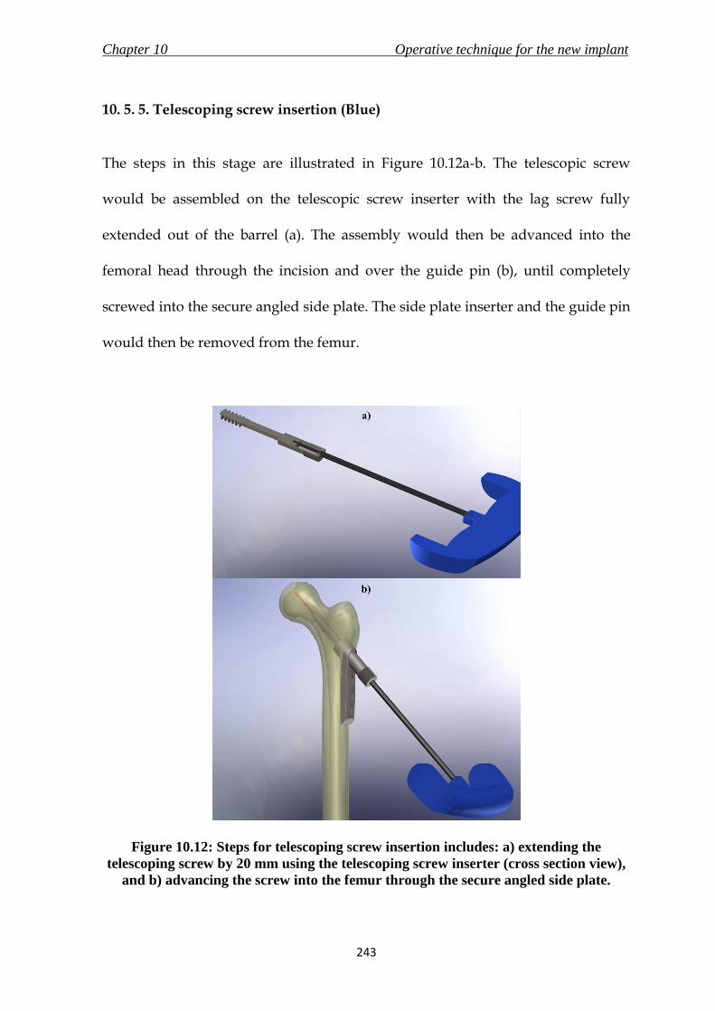
Chapter 10 Operative technique for the new implant
243
10. 5. 5. Telescoping screw insertion (Blue)
The steps in this stage are illustrated in Figure 10.12a-b. The telescopic screw
would be assembled on the telescopic screw inserter with the lag screw fully
extended out of the barrel (a). The assembly would then be advanced into the
femoral head through the incision and over the guide pin (b), until completely
screwed into the secure angled side plate. The side plate inserter and the guide pin
would then be removed from the femur.
Figure 10.12: Steps for telescoping screw insertion includes: a) extending the
telescoping screw by 20 mm using the telescoping screw inserter (cross section view),
and b) advancing the screw into the femur through the secure angled side plate.
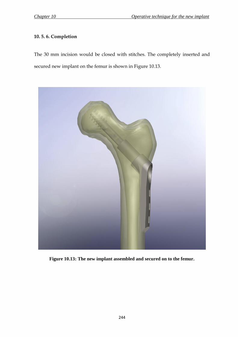
Chapter 10 Operative technique for the new implant
244
10. 5. 6. Completion
The 30 mm incision would be closed with stitches. The completely inserted and
secured new implant on the femur is shown in Figure 10.13.
Figure 10.13: The new implant assembled and secured on to the femur.

Chapter 10 Operative technique for the new implant
245
10. 6. Summary
The summarising points of this chapter are listed below.
i. The chapter highlighted the features and design attributes of the new
implant and associated instruments. The new instruments could either
directly replace their counterparts in the existing generic DHS surgery, or be
a part of the instrument set to be used in the surgical procedure of the new
implant.
ii. The surgery described in this chapter used a minimally invasive approach
with a maximum required incision of 30 mm to insert the new implant.
iii. The surgical procedure of the new implant was divided into four stages, each
denoted by a unique colour – guide pin placement (green), reaming and
tapping (yellow), side plate fixation (orange) and finally telescoping screw
insertion (blue). The T-handles on instruments would be colour-coded
corresponding to its stage of use.

Chapter 11 Conclusions
246
The research presented in this thesis was initiated on Prof. N. Maffulli’s
observation for a need of minimally invasive approach for the surgical treatment
of fractures of the proximal femur. The research concluded with the development
of three new medical devices taken through a thorough medical device design
process to facilitate minimally invasive surgery (MIS) for these fractures.
In Chapter 3, a feasibility study was conducted to investigate the fractures of the
proximal femur, and identify the medical devices currently used in the market for
their treatment. The results showed that surgical treatment of these fractures was
possible either with Intra-Medullary fixation devices or Dynamic hip screw (DHS);
of which DHS was considered the standard implant for proximal femur fracture
fixation. A further assessment of the DHS implant, associated instruments and
surgical technique, identified the angle guide, the T-handle and the DHS implant
as key medical devices to allow for MIS of DHS. A review of commercially
CONCLUSIONS

Chapter 11 Conclusions
247
available implants which utilise MIS for the treatment of these fractures also
revealed the superiority of the DHS because of the simple surgical procedure and
decades of use. Therefore, the objective of this research was to redevelop the three
identified medical devices to reduce the incision length for the implantation to less
than 30 mm (from the existing 100 – 150 mm), whilst attempting to maintain the
surgical technique utilised to implant the DHS.
The angle guide was the first to be redesigned, as it was discovered to be the only
instrument during the feasibility study that prevented a viable (safe) MIS with less
than 30 mm incision using the existing set of instruments and implant with a
modified operative technique. Hence, the new angle guide would not only replace
the existing device to aid in MIS, but also be a part of the operative technique for
the new implant that was to be developed at a later stage of the research. In
Chapter 4, the concept of the new angle guide was generated following an in
depth analysis of the current device, and compilation of detailed design
specifications which conformed to the standard for surgical instruments – BS EN
12011 (1998). Additional to the functional requirement and the need to reduce the
incision length for utilising the device, it was also considered necessary to design
an alternative base for the new angle guide to replace the existing prongs to grip
the bone and provide improved stability. The new angle guide was described in
detail in Chapter 6 and it successfully passed design verification methods such as
finite element analysis (FEA) and risk analysis.

Chapter 11 Conclusions
248
Chapter 5 described an in vitro experiment that was conducted to measure the
static coefficient of friction between bone and candidate materials for the new base
of the new angle guide in presence of a blood analogue solution. The inclusion of
blood analogue solution in the testing methods mimicked the slippery surface of
bone due to presence of blood and hence increased the authenticity of the
experiment. Apart from the standard stainless steel surface, silicone elastomers
were selected due to their properties of biocompatibility, resistance to sterilisation
methods and ability to mould on application of force without plastic deformation.
The determination of values of static coefficient of friction between bone and these
materials aided in selecting a new base material which would provide the best
grip on the slippery bone surface. In general, textured surfaces of stainless steel
provided better grip than silicone elastomers and the highest value of coefficient
of friction was demonstrated when bone interfaced with stainless steel surface
prepared by spark erosion. However, it was also necessary for the new base to
provide stability on the curved bone surface, and hence Silastic Q7-4780 (silicone
elastomer grade with the highest static friction coefficient) was also selected. The
base of the new angle guide was a combination of these two materials. The results
generated from this test could also be used in design processes of other medical
devices in the future as no publications were found which provided these values.
The custom built testing rig was designed such that it can also be used for
experiments to determine static coefficient of friction values of other materials.
Chapter 11 Conclusions
249
The redesigning of the DHS instruments’ T-handle involved a design process
which emphasized on ergonomics. The specifications for a comfortable and
effective T-handle were derived from published literature relating to other
industries, and were combined with the requirements of a surgical instrument as
stated in BS EN 12011 (1998). Although comfortable T-handles are manufactured
and supplied by reputable orthopaedic implant manufacturers such as Stryker
(Kalamazoo, Michigan, USA) and B. Braun Melsungen AG (Melsungen,
Germany), no publications were found on design specifications of a T-handle
based on ergonomic principles. The resulting new ergonomic T-handle design, like
the new angle guide, was proposed for use with the existing DHS surgical
instruments, and in the surgical technique for the new implant.
The final leg of this research involved designing a new implant (presented in
Chapters 8 to 10) that utilised the sliding principle of the DHS implant, avoided
the complications caused due to the existing DHS, maintained the surgical
technique of the DHS and required an incision length of less than 30 mm for
insertion to treat the fractures of the proximal femur. These objectives were used
to produce a product design specification for the new implant that conformed to
the requirements stated in the standards for general surgical implants, implants
for osteosynthesis and for devices for the fixation of adult femur ends. The new
implant assembly consisted of a telescoping screw which combined the lag screw
of the DHS with a close ended barrel to avoid lag screw cut-outs (regarded as the
Chapter 11 Conclusions
250
highest complication linked to the DHS), and a locking angled side plate that
would enhance the fixation and stability of the implant on the femur. A prototype
of the new implant was manufactured and successfully underwent mechanical
testing as required by ASTM F-384 (2006). The design was also verified using risk
analysis and FEA. Chapter 10 exhibited the surgical technique for the new implant
using a minimally invasive approach. The operative technique utilised the new
angle guide along with the new ergonomic T-handle and other existing DHS
instruments for the implantation.
Although the design process used to develop the three medical devices were
comprehensive, the selected designs of the three new medical devices need further
work before they could be passed on for manufacturing and eventual regulatory
approval. The new devices need further testing with prototypes manufactured to
exact specifications. Also, packaging and manufacturing aspect of the total design
approach were ignored during the design process mentioned in the research,
although their requirements were stated in the respective device’s PDS. However,
the aim of this research was to develop new medical devices to enable MIS for
treatment of fractures of proximal femur. The designs of the medical devices
presented in this research are viable, conform to the regulatory standards, and
would be competitive due to their own unique advantages in the global market.
Chapter 11 Conclusions
251
The future work required on the new medical devices is listed below.
Prototypes of the three new medical devices designed in this research
should be manufactured to exact specifications. Manufactured samples of
the new implant are required for an elaborate and accurate mechanical
testing (static and cyclic). The samples should also be assessed by surgeons
and the appropriate surgical staff for practicality and performance. It would
also be beneficial to survey surgeon’s reactions and suggestions through a
practical session, specifically for the usability of the new angle guide,
comfort provided by the ergonomic T-handle, and surgical procedure of the
new implant.
Appropriate packaging design, manufacturing techniques, engineering
drawings according to the final materials selected and a bill of materials
need to be prepared for the new medical devices and the other instruments
that would form a part of the new instrument set for MIS of DHS.
Clinical investigation of the new medical devices on live human subjects
and the proceeding analysis of the design is very important before the
design is forwarded to the manufacturer for regulatory approval and sale in
the market.

Appendix A Surgeon’s perspective on a new base material
252
A. 1. Introduction
A new base material was to be selected for the design of the new angle guide to
replace the existing prongs (section 4.4). Apart from conducting an in vitro test to
measure the static coefficient of friction of the selected materials (three grades of
silicone elastomer; three different surface preparations of the stainless steel
surface) described in Chapter 5, it was also decided to evaluate the surgeon’s
perspective of the selected materials as the new base material for an instrument-
bone surface interface in an angle guide. The survey was conducted at the City
General Hospital (Stoke-on-Trent, UK) on the 7th of December, 2007 by the author
and Dr. D.E.T. Shepherd (PhD supervisor), and was organised by Prof. N.
Maffulli. The experiment was attended by ten orthopaedic surgeons. It was
portrayed to the surgeons that the experiment would aid in designing any
orthopaedic instrument where base material and bone surface interaction would
be involved. Along with the base material, the thickness and length of a T-handle
SURGEON’S PERSPECTIVE ON A
NEW BASE MATERIAL

Appendix A Surgeon’s perspective on a new base material
253
was also assessed to aid in the design process of the new ergonomic T-handle
(Chapter 7). Unfortunately, the survey proved inconclusive in selecting a new base
material because of the reasons mentioned in section A.4; hence the results were
not included in the design process of the medical devices. The following sections
describe the experiment in detail, and the questionnaire used during the
experiment is included towards the end of this appendix in section A.6.
A. 2. Materials and Methods
A. 2. 1. Instruments
Five instruments, named A - E were used for this experiment. All the instruments
were manufactured by welding a mild steel cylindrical rod, 10 mm in diameter
and 110 mm long to the centre of a mild steel base, with dimension of 60 mm 15
mm 2 mm. Instruments C, D and E were fitted with a beech wood handle of 25
mm in diameter and 115 mm long. The handle on instruments A and B had a
diameter of 30 mm and was 95 mm long.
The bases of all the five instruments were different from each other. A base was
cut off from a generic design of DHS 135 degrees angle guide, and then welded on
to the cylindrical rod at the centre to make instrument A. The base of instrument C
was machined to have a radius of curvature of 20 mm, and then, as with the base

Appendix A Surgeon’s perspective on a new base material
254
of instrument B, it was also attached to a sheet of Silastic Q7-4720 silicone of the
same dimension as the base using Araldite (Huntsman, Switzerland). Instrument
D had a sheet of Silastic Q7-4780 silicone attached to the base. The base of
instrument E was roughened to a non-specific Ra value using a wire mesh.
A. 2. 2. Setup of Apparatus
A SawBone femur (Sawbones Europe AB, Sweden) was cut just above the vastus
lateralis ridge, and approximately 100 mm below the ridge, as this is the area of
concern for an angle guide. The femur was also cut off medially. All the sides
which were cut off were smoothened using a sanding machine. The cut femur was
then attached with Araldite to the base of a 5-sided clear box (150 mm 150 mm
150 mm) made of PolyMethyl MethAcrylate (PMMA) clear acrylic sheets.. The
bone was then submerged in a blood analogue solution (section 5.4.4). Enough
solution was poured into the box to cover the bone-instrument interface during
the experiment.
A. 2. 3. Questionnaire and respondents
The questionnaire was designed specifically to assess the comfort levels, and the
confidence in the surgeon while using the instruments. These parameters were
measured on the basis of the base material and the handle size. Each instrument
would be given a score out of 8 (2 questions – diameter and thickness) for the

Appendix A Surgeon’s perspective on a new base material
255
different handles experience and out of 16 (4 questions – stability, grip,
complement fit and comfort) for the different base materials. These were followed
by subjective questions on their experience with instruments which interface
with/ are placed on the bone surface. The questionnaire used for the survey is
included at the end of this appendix.
The respondents included two orthopaedic consultants, six orthopaedic specialist
registrars, one senior house office and one staff grade surgeon.
A. 2. 4. Evaluating the surgeon’s perspective
Each assessor was called to the setup area, and asked to pick up one of the five
pieces of paper with the instrument code on it. The instrument was used by the
surgeon (Figure A.1.). At the same time, the six questions relating to the handle
and the base material were asked. This step was repeated until all the 5 different
instruments were tested. The assessor was then asked to complete the rest of the
questionnaire.
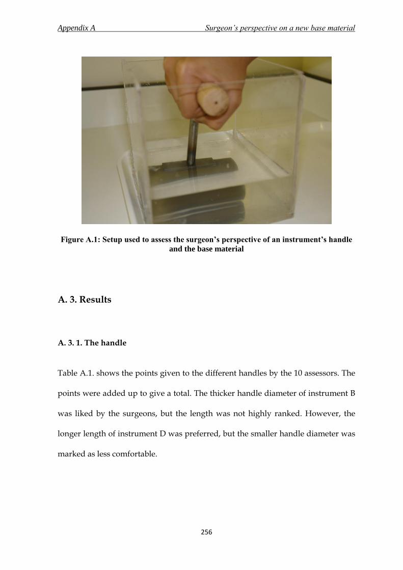
Appendix A Surgeon’s perspective on a new base material
256
Figure A.1: Setup used to assess the surgeon’s perspective of an instrument’s handle
and the base material
A. 3. Results
A. 3. 1. The handle
Table A.1. shows the points given to the different handles by the 10 assessors. The
points were added up to give a total. The thicker handle diameter of instrument B
was liked by the surgeons, but the length was not highly ranked. However, the
longer length of instrument D was preferred, but the smaller handle diameter was
marked as less comfortable.

Appendix A Surgeon’s perspective on a new base material
257
A. 3. 2. The base material
Table A.2. summarises the answers to the questions based on the base materials of
the five different instruments. Each base material of an instrument was to be
assessed out of 16 points – 4 per question. The results were added to give an
overall standing of the instrument out of 160 points.
Instrument A, the current base with prongs, was selected as the best by the
surgeons. Softer silicone elastomer, i.e. instruments B and C were preferred over
harder silicone elastomer – instrument D. The silicone elastomer did not make as
much of an impact (difference between instruments B and E), as the curved base
did, which is seen in the results for instrument C.
Instrument A provided the best stability, grip, complement fit and comfort to the
surgeons. On the other hand, instrument D was consistently rated the worst for all
the above factors. Instrument B provided a better stability, and E was better for
grip and comfort, and both were similar for complement fit. Instrument C was the
second best for all the factors.
A. 3. 3. General questions
These questions were optional, and the assessors were asked to fill in the boxes at
their own convenience. Many answers were left blank, and some assessors
Appendix A Surgeon’s perspective on a new base material
258
provided more than one answer to a question. Hence, the results do not actually
display the percentage of the assessor that chose one answer, but they show the
percentage of the recorded answers. 80% (8 of 10) of the answers acknowledged
the difficulty in placing an instrument on the bone surface. The main reason (59% -
7 of 12) was slippage of the instrument on the bone surface. Another major factor
was the stability of the instrument (17% - 2 of 12) on the bone surface. Poorly
designed instrument, insufficient access to the operating region, and the learning
curve of using the instrument were equally contributing factors (8% - 1 of 12). The
answers to “how to improve the instrument – question 10” included a new
concave base (29% - 2 of 7), a better handle (29% - 2 of 7), better grip (29% 2 of 7)
and by designing the instrument to experience less strain on hand (14% - 1 of 7).
Table A.1. Handle design ratings summary

Appendix A Surgeon’s perspective on a new base material
259
Table A.2. Base materials ratings summary
A. 4. Discussion
The results of the handle questions leaned towards a longer and a thicker handle.
All the surgeons that took part in the experiment were male, which could have
biased the results.
Regarding the base material, 80% of the answers suggested a problem with the
current design of a bone resting instrument, and 59% suggested the problem to be
slippage. However, the surgeons marked the current base material with the
prongs as the best, and gave it almost full marks for every question, even though
they were not asked to mark the base material relative to each other. One of the
explanations for this result could be the familiarity with the base material. This
instrument has been in use for decades, and it is therefore possible that the

Appendix A Surgeon’s perspective on a new base material
260
assessors gave a higher mark to the instrument they were more familiar with. The
test was conducted towards the end of the working day on a Friday, and the
assessors had a long day at work. This could have affected the results, and actually
caused the higher marking of the familiar instrument. Instrument C, which was an
intended success for a new base material was marked higher than Instrument A,
the generic design, by a Consultant and a Senior House Officer. All the registrars
except one marked Instrument A higher than C.
In the present investigation, the current design was marked the highest, followed
by a softer silicone elastomer lining over a curved base. The softer silicone
elastomer (Q7-4720) was preferred over the harder one (Q7-4780). Another
observation was that the curved base surface was preferred to a flat one. In fact, it
was even suggested by two assessors that a concave base surface would enhance
the grip and stability achieved by the instrument on the bone.
A. 5. Conclusions
The test was unable to give conclusive answers towards choosing a better base
material for the instruments, but it did provide a very useful insight into the way
surgeons’ perceive and use the instrument, and also on the different factors that
are important to improve the surgeons’ comfort while using the instrument.

Appendix A Surgeon’s perspective on a new base material
261
A. 6. Questionnaire
7th
December 2007
Bone – instrument interface experiment
Respected Sir/ Madam,
I am currently a PhD student in the Biomedical Engineering Research Group at The
University of Birmingham, working under the supervision of Dr. Duncan Shepherd and
Prof. David Hukins. My research includes studying the factors that affect the level of
comfort experienced by surgeons while using orthopaedic instruments.
The aim of this experiment is to determine an appropriate material that would be most
comfortable to use for the interface of the instrument’s base with the bone.
The setup includes 5 instruments (A – E) of identical dimensions with different base
materials. The handle size has also been changed in one of the instruments. You would be
required to place each instrument at the specified position on the bone, and answer the
series of questions by rating each instrument from 1 to 4; with 1 being the worst to 4 being
the best.
The questionnaire includes some general questions which would aid in designing a better
base for numerous orthopaedic instruments that interact with the bone surface.
All responses will be treated with the utmost confidence and the results will only be
presented in aggregated format.
I would like to thank you for participating in this experiment. Any feedback or extra
comments would be highly appreciated.
Kindly contact me regarding any queries about the experiment.
Yours sincerely,
Jugal Parekh
Ph.D. Research Student
Bio-medical Engineering Research Centre
University of Birmingham, U.K.
http://www.bioeng.bham.ac.uk/
Tel: +44 (0) 121 414 3622
Mobile: +44 (0) 77867 33477
Email: [email protected]

Appendix A Surgeon’s perspective on a new base material
262
Kindly state your profession
Please specify your current position
This questionnaire consists of 11 questions, with 6 related to your experience while using
the instruments (A – E) during the experiment.
Kindly answer all the questions.
Rate the following questions from 1 to 4; 1 being the worst and 4 being the best. The same
rating could be applied to more than one instrument.
The following two questions are based on the handle of the instrument:
1. Please rate on the diameter of the handle and the comfort fit it provided in your
hand
1 2 3 4
B
D
2. Please rate on the length of the handle and the comfort fit it provided in your hand
1 2 3 4
B
D

Appendix A Surgeon’s perspective on a new base material
263
The following three questions relate to the base of the instrument and its fit with the bone:
3. Please rate the stability of the instrument on the bone based on the base material of
the respective instrument
1 2 3 4
A
B
C
D
E
4. Please rate the amount of grip provided by the instrument on the bone due to the
base material, i.e. the prevention of slipping because of the base material
1 2 3 4
A
B
C
D
E
5. Kindly rate the fit of the instrument on the curvature of the surface of the bone, i.e.
how well did the instrument sit on the bone?
1 2 3 4
A
B
C
D
E

Appendix A Surgeon’s perspective on a new base material
264
The following question is based on the overall experience of the instrument
6. Please rate the comfort while using the instrument
1 2 3 4
A
B
C
D
E
The following questions are based on your experience with orthopaedic instruments. You
could refer and discuss with your colleagues for answering the following questions.
7. Have you experienced any difficulties while placing an instrument onto a bone
surface?
Yes No
8. If you answered yes to question 7, please state any such experiences and the
reason (stability, slipping issues)

Appendix A Surgeon’s perspective on a new base material
265
9. What bone surface instruments do you regularly use? (e.g. Angle guide)
10. Kindly state any other factors that you consider important in improving the bone –
instrument interface
11. Any additional comments
Thank you for your time!

Appendix B The new implant- model 1
266
B.1. Introduction
It was stated in section 9.2 that model 1 failed during the mechanical testing
discussed in Chapter 9. Hence, the dimensions were reassessed and model 2 was
used for the detailed design process. Model 2 was regarded as the new implant.
This appendix shows model 1 of the new implant in Figure B.1, followed by the
engineering drawings in Figures B.2 and B.3, and finally the modified
manufactured prototype along with the fracture and excessive bending it endured
during the static loading test in Figure B.4.
THE NEW IMPLANT –
MODEL 1

Appendix B The new implant- model 1
267
Figure B.1: Model 1 of the new implant

Appendix B The new implant- model 1
268
Figure B.2: Engineering drawing of the angled side plate of model 1 of the new
implant

Appendix B The new implant- model 1
269
Figure B.3: Engineering drawing of the telescoping screw of model 1 of the new
implant

Appendix B The new implant- model 1
270
Figure B.4: Static loading test on the modified manufactured prototype of model 1
resulted in excessive bending of the angled side plate and fracture of barrel of the
telescoping screw

Appendix C New instruments for the new implant
271
C.1. Introduction
The surgical technique (Chapter 10) required two additional new instruments for
insertion of the new implant into the proximal femur. They were – a) side plate
inserter (section 10.4.4), and b) telescoping screw inserter (section 10.4.5). This
appendix shows the engineering drawings of the new instruments in Figure C.1
and C.2. The engineering drawings do not include the new ergonomic T-handle
(Chapter 7).
NEW INSTRUMENTS FOR THE
NEW IMPLANT
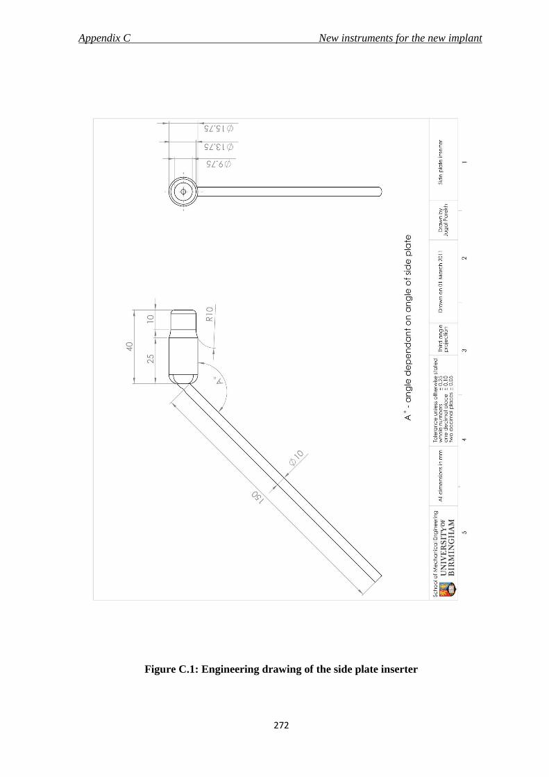
Appendix C New instruments for the new implant
272
Figure C.1: Engineering drawing of the side plate inserter

Appendix C New instruments for the new implant
273
Figure C.2: Engineering drawing of the telescoping screw inserter

List of References
274
LIST OF REFERENCES
Ahn, J. and Bernstein, J. (2010) Fractures in brief: intertrochanteric hip fractures.
Clinical Orthopaedics and Related Research, 468, 1450-1452.
Aitchison, G. A., Hukins, D. W. L., Parry, J. J., Shepherd, D. E. T. and Trotman, S.
G. (2009) A review of the design process for implantable orthopedic medical
devices. Open Biomedical Engineering Journal, 3, 21-27.
Aros, B., Tosteson, A. N., Gottlieb, D. J. and Koval, K. J. (2008) Is a sliding hip
screw or im nail the preferred implant for intertrochanteric fracture fixation?
Clinical Orthopaedics and Related Research, 466, 2827-2832.
ASTM F384 (2006): Standard specifications and test methods for metallic angled
orthopedic fracture fixation devices. Pennsylvania, American Society for Testing and
Materials (ASTM) International.
ASTM G115 (2004) Standard guide for measuring and reporting friction coefficients.
Pennsylvania, American Society for Testing and Materials (ASTM) International.
Avallone, E., Baumeister, T., Sadegh, A. Standard handbook for mechanical engineers,
11th edition, New York, McGraw Hill
Baumgaertner, M.R. (1998) Surgical technique for compression hip screw plates and
nails, London, Smith & Nephew plc.
Baumgaertner, M.R., Curtin, S.L., Lindskog, D.M., Keggi, J.M. The value of tip-
apex distance in predicting failure of fixation of peritrochanteric fractures of the
hip. Journal of Bone and Joint Surgery (American), 77, 1058-64
Berguer, R. (1998) Surgical technology and the ergonomics of laparoscopic
instruments Surgical Endoscopy, 12, 458-462.
Berguer, R. (1999) Surgery and ergonomics. Archives of Surgery, 134, 1011-1016.
Berguer, R. and Hreljac, A. (2004) The relationship between hand size and
difficulty using surgical instruments: a survey of 726 laparoscopic surgeons.
Surgical Endoscopy, 18, 508-512.

List of References
275
Bhushan, B. (2001) Modern Tribology handbook - principles of tribology, London, CRC
Press
Bland, M. (2000) An Introduction to Medical Statistics, 3rd edition, Oxford, Oxford
University Press
Bolhofner, B., Russo, P., Carmen, B. (1999) Results of intertrochanteric femur
fractures treated with a 135-degree sliding screw with a two-hole side plate.
Journal of Orthopaedic Trauma, 13, 5-8
Brandt, E., Verdonschot, N., Van Vugt, A. and Van Kampen, A. (2006)
Biomechanical analysis of the percutaneous compression plate and sliding hip
screw in intracapsular hip fractures: experimental assessment using synthetic and
cadaver bones Injury, 37, 979-983.
Brandt, E., Verdonschot, N., van Vugt, A., Van Kampen, A. (2010) Biomechanical
analysis of the sliding hip screw, cannulated screws and Targon FN in
intracapsular hip fractures in cadaver femora. Injury, 42, 183-87
BS 3531-15:1992; ISO 8615:1991: Implants for osteosynthesis - Part 15: Specifications for
devices for the fixation of the ends of the femur in adults. London, British Standards
Institution
BS 3531-23.2:1993; ISO 9269:1988: Implants for osteosynthesis - Part 23: Bone plates -
Section 23.2 specifications for holes and slots for use with screws of 4.5 mm, 4.2 mm, 4.0
mm, 3.9 mm, 3.5 mm and 2.9 mm nominal sizes, London, British standards institution
BS 7254-2:1990: Orthopaedic implants. Specification for general requirements for
materials and finish. London, British Standards Institution
BS EN 12011:1998: Instrumentation to be used in association with non-active surgical
implants - General requirements. London, British Standards Institution
BS EN 552:1994: Sterilisation of medical devices - Validation and routine control of
sterilization by irradiation, London, British Standards Institution
BS EN 554:1994: Sterilization of medical devices - Validation and routine control of
sterilization by moist heat. London, British Standards Institution

List of References
276
BS EN 556-1:2001: Sterilization of medical devices - Requirements for medical devices to
be designated "Sterile" - Part 1: Requirements for terminally sterilized medical devices.
London, British Standards Institution
BS EN 556-2:2003: Sterilization of medical devices - Requirements for medical devices to
be designated "Sterile" - Part 2: Requirements for aseptically processed medical devices,
London, British Standards Institution
BS EN 1041:2008: Information supplied by the manufacturer of medical devices. London,
British Standards Institution
BS EN ISO 11137-1:2006: Sterilization of health care products. Radiation. Requirements
for development, validation and routine control of a sterilization process for medical
devices. London, British Standards Institution
BS EN ISO 11137-2:2007: Sterilization of health care products. Radiation. Establishing
the sterilization dose. London, British Standards Institution
BS EN ISO 11137-3:2006: Sterilization of health care products. Radiation. Guidance on
dosimetric aspects. London, British Standards Institution
BS EN ISO 11607-1:2009: Packaging for terminally sterilized medical devices.
Requirements for materials, sterile barrier systems and packaging systems. London,
British Standards Institution
BS EN ISO 14155:2011: Clinical investigation of medical devices for human subjects.
Good clinical practice. London, British Standards Institution
BS EN ISO 14602:2010: Non-active surgical implants-Implants for osteosynthesis -
Particular requirements (ISO 14602:2010). London, British Standards Institution
BS EN ISO 14630: 2009: Non-active surgical implants - General requirements (ISO
14630:2008). London, British Standards Institution
BS EN ISO 14971: 2007: Medical devices - application of risk management to medical
devices. London, British Standards Institution

List of References
277
BS EN ISO 15223: 2009: Medical devices – Symbols to be used with medical device labels,
labelling and information to be supplied – Part 1: General requirements. London, British
Standards Institution
BS EN ISO 16061:2008: Instrumentation for use in association with non-active surgical
implants - General requirements (ISO 16061:2008). London, British Standards
Institution
BS EN ISO 16061:2009: Instrumentation for use in association with non-active surgical
implants - general requirements (ISO 16061:2008, Corrected version 2009-03-
15).London, British Standards Institution
BS EN ISO 17664: 2004: Sterilization of medical devices. Information to be provided by
the manufacturer for the processing of resterilisable medical devices. London, British
Standards Institution
BS EN ISO 17665-1:2006: Sterilization of health care products. Moist heat. Requirements
for the development, validation and routine control of a sterilization process for medical
devices. London, British Standards Institution
BS ISO 5832-1:2007: Implants for surgery - Metallic materials - Part 1: Wrought stainless
steel. London, British Standards Institution.
Buchel, D., Marvik, R., Hallabrin, B. and Matern, U. (2010) Ergonomics of
disposable handles for minimally invasive surgery. Surgical Endoscopy, 24, 992-
1004.
Burdin, Ph., Langlais, F., Ropars, M., Belot, N., D'Bouk M., Lambotte, J. C. (2006)
Osteosyntheses mini invasives des fractures du femur proximal. Annales
orthopédiques de l'Ouest, 38, 50-6
Butt, M. S., Krikler, S. J., Nafie, S. and Ali, M. S. (1995) Comparison of dynamic hip
screw and gamma nail: a prospective, randomized, controlled trial. Injury, 26, 615-
618.
Callaghan, J. J., Rossenber, A. G., Rubash, H.E. (2007) The Adult Hips, 2nd edition,
Lippincott, Williams & Wilkins

List of References
278
Canale, S. T. (2002), Campbell's operative orthopaedics, 10th edition, Philidelphia,
Mosby
Childs, P. (2004) Mechanical design, 2nd edition, Oxford, Elsevier Butterworth-
Heinermann
Chirodian, N., Arch, B., Parker, M.J. (2005) Sliding hip screw fixation of
trochanteric hip fractures: outcome of 1024 procedures. Injury, 36, 793-800
Chong, K. W., Wong, M. K., Rikhraj, I. S. and Howe, T. S. (2006) The use of
computer navigation in performing minimally invasive surgery for
intertrochanteric hip fractures--The experience in Singapore. Injury, 37, 755-62.
Cochran, D.J., Riley, M.W. (1986) The effects of handle shape and size on exerted
forces. Human factors, 28, 253-65
Colas, A. and Curtis, J. (2004) Medical applications of silicones. In Ratner, B.,
Hoffman, A., Schoen, F., Lemons, J. (Eds) An introduction to materials in medicine,
(pp 697-707)2nd edition, London, Elsevier Academic Press
Dammak, M., Shirazi-Adi, A., Schwartz, M., Gustavson, L. (1997) Friction
properties at the bone-metal interface: comparison of four different porous metal
surfaces. Journal of Biomedical Materials Research, 35, 329-36
Das, B., Jongkol, P. and Ngui, S. (2005) Snap-on-handles for a non-powered
hacksaw: an ergonomics evaluation, redesign and testing. Ergonomics, 48, 78-97.
Dittel, K.K. and Rapp, M. (2008) The double dynamic martin screw (DMS), Germany,
Steinkopff Verlag
Esser, M. P., Kassab, J. Y. and Jones, D. H. (1986) Trochanteric fractures of the
femur. A randomised prospective trial comparing the Jewett nail-plate with the
dynamic hip screw. Journal of Bone and Joint Surgery (British), 68, 557-560.
Evans, P.J. and McGrory, B. J. (2002) Fractures of the Proximal Femur - Clinical
review article. Hospital Physician, 30-8
FDA 21CFR820 Quality System Regulation. Rockville, Maryland, USA: Food and
Drug Administration, 2006.

List of References
279
Flores, L.A., Harrington, I.J., Heller, M. (1990) The stability of intertrochanteric
fractures treated with a sliding screw-plate. Journal of Bone and Joint Surgery
(British), 72, 37-40
Frigg, R. (1994) Two-part angle plate. U.S. Patent no 5,300,074, filed Dec 6, 1991 and
published April 5, 1994
Gotfried, Y. (2000) Percutaneous compression plating of intertrochanteric hip
fractures. Journal of Orthopaedic Trauma, 14, 490-495.
Gundle, R., Gargan, M.F., Simpson, A.H. (1995) How to minimize failures of
fixation of unstable intertrochanteric fractures. Injury, 26, 611-4
Haleem, S., Lutchman, L., Mayahi, R., Grice, J. E. and Parker, M. J. (2008) Mortality
following hip fracture: trends and geographical variations over the last 40 years
Injury, 39, 1157-1163.
Hamilton, R.J. and Kelly, I.G. (2004) Evaluation of the long intra-medullary hip
screw. Injury, 35, 1264-9
Hamrock, B.J., Schmid, S.R. and Jacobson, B.O. (2004) Fundamentals of Fluid Film
Lubrication. London, CRC Press
Harper, C. (2001), Handbook of materials for product design. 3rd edition, New York,
McGraw-Hill
Harrington, P., Nihal, A., Singhania, A.K., Howell, F.R. (2002) Intramedullary hip
screw versus sliding hip screw for unstable intertrochanteric femoral fractures in
the elderly. Injury, 33, 23-8
Hebela, N., Smith, D.G. and Keenan, M.A. (2004) What’s new in Orthopaedic Rehabilitation. Journal of Bone and Joint Surgery (American), 86, 2577-81
Hill, D. (1998) Design engineering of biomaterials for medical device, West sussex, John
Wiley & sons
Ho, M., Garau, G., Walley, G., Oliva, F., Panni, A.S., Longo, U.G., Maffulli, N.
(2009) Minimally invasive dynamic hip screw for fixation of hip fractures.
International Orthopaedics, 33, 555-60

List of References
280
Hoaglund F.T. and Low, W.D. (1980) Anatomy of the femoral neck and head, with
comparative data from Caucasians and Hong Kong Chinese. Clinical Orthopaedics
and Related Research, 152, 10-16
Holt, G., Smith, R., Duncan, K., Hutchison, J. D. and Gregori, A. (2008)
Epidemiology and outcome after hip fracture in the under 65s-evidence from the
Scottish Hip Fracture Audit. Injury, 39, 1175-1181.
Jewell, D. P., Gheduzzi, S., Mitchell, M. S. and Miles, A. W. (2008) Locking plates
increase the strength of dynamic hip screws Injury, 39, 209-212.
Karwowski (2001) International encyclopedia of ergonomics and human factors, 2nd
edition, London, Taylor & Francis
Karwowski, W. and Marras, W.S. (2003) Occupational ergonomics: principles of work
design, London, CRC Press
Kim, W. Y., Han, C. H., Park, J. I. and Kim, J. Y. (2001) Failure of intertrochanteric
fracture fixation with a dynamic hip screw in relation to pre-operative fracture
stability and osteoporosis International Orthopaedics, 25, 360-362.
Kong, Y. K., Freivalds, A. and Kim, S. E. (2004) Evaluation of handles in a
maximum gripping task. Ergonomics, 47, 1350-64.
Kong, Y. K., Lowe, B. D., Lee, S. J. and Krieg, E. F. (2008) Evaluation of handle
shapes for screwdriving. Applied Ergonomics, 39, 191-198.
Korvick, D. L., Newbrey, J. W., Bagby, G. W., Pettit, G. D. and Lincoln, J. D. (1989)
Stress shielding reduced by a silicon plate-bone interface. A canine experiment.
Acta Orthopaedic Scandanavia, 60, 611-616.
Kumar, A. J., Parmar, V. N., Kolpattil, S., Humad, S., Williams, S. C. and Harper,
W. M. (2007) Significance of hip rotation on measurement of 'Tip Apex Distance'
during fixation of extracapsular proximal femoral fractures. Injury, 38, 792-96.
Laohapoonrungsee, A., Arpornchayanon, O. and Phornputkul, C. (2005) Two-hole
side-plate DHS in the treatment of intertrochanteric fracture: results and
complications. Injury, 36, 1355-1360.

List of References
281
Lee, Y. S., Huang, H. L., Lo, T. Y. and Huang, C. R. (2007) Dynamic hip screw in
the treatment of intertrochanteric fractures: a comparison of two fixation methods.
International Orthopaedics, 31, 683-688.
Lefauveau, P. and Fardellone, P. (2004) Extraskeletal risk factors for fractures of
the proximal femur. Joint Bone Spine, 71, 14-17.
Leung, W. Y. and Tsang, W. L. (2008) Conventional muscle-reflection approach
versus mini-incision muscle-splitting approach in dynamic hip screw fixation.
Journal of Orthopaedic Surgery (Hong Kong), 16, 156-161.
Liang, J., Li, K., Liao, Q., Lei, G., Hu, Y., Zhu, Y. and He, A. (2009) Anatomic data
of the proximal femur and its clinical significance. Journal of Central South
University. Medical Sciences. 34, 811-814.
Marks, R. (2009) Hip fracture epidemiological trends, outcomes, and risk factors,
1970 - 2009. International Journal of General Medicine, 3, 1-17
Massey, L.K. (2005) The effects of sterilization methods on plastics and elastomers, 2nd
edition, New York, William Andrew, inc
Matern, U. and Waller, P. (1999) Instruments for minimally invasive surgery:
principles of ergonomic handles. Surgical Endoscopy, 13, 174-182.
Matern, U., Eichenlaub, M., Waller, P. and Ruckauer, K. (1999) MIS instruments.
An experimental comparison of various ergonomic handles and their design.
Surgical Endoscopy, 13, 756-62.
McLoughlin, S.W., Wheeler, D.L., Rider, J., Bolhofner, B. (2000) Biomechanical
evaluation of the dynamic hip screw with two-and four-hole side plates. Journal of
Orthopaedic Trauma, 14, 318-23
MDD, Directive 98/79/EC of the European Parliament and of the Council of 27
October 1998 on in vitro diagnostic medical devices (1998), Official Journal of
European Communities, L331, 1-37
Mithal, A., Dhingra, V. and Lau, E. (2009) The Asian Audit: Epidemiology, costs and burden of osteoporosis in Asia 2009. International Osteoporosis Foundation. Available at http://bit.ly/dUBzN6

List of References
282
Napier, J. R. (1956) The prehensile movements of the human hand. Journal of Bone
and Joint Surgery (British), 38-B, 902-913.
O' Leary, J.P. (2004) Medical product design. In Kutz, M. (Ed.) Standard handbook of
biomedical engineering and design (pp. 19.1-19.19) New York, McGraw Hill
Parker, M.J., Handol, H.H. (2009) Extramedullary fixation implants and external
fixators for extracapsular hip fractures in adults (Review). Conchrane Database
Systematic reviews
Peyser, A., Weil, Y. A., Brocke, L., Sela, Y., Mosheiff, R., Mattan, Y., Manor, O. and
Liebergall, M. (2007) A prospective, randomised study comparing the
percutaneous compression plate and the compression hip screw for the treatment
of intertrochanteric fractures of the hip. Journal of Bone and Joint Surgery (British),
89, 1210-1217.
Peyser, A., Weil, Y., Brocke, L., Manor, O., Mosheiff, R. and Liebergall, M. (2005)
Percutaneous compression plating versus compression hip screw fixation for the
treatment of intertrochanteric hip fractures Injury, 36, 1343-1349.
Peyser, A., Weil, Y., Liebergall, M. and Mosheiff, R. (2005) Percutaneous
compression plating for intertrochanteric fractures. Surgical technique, tips for
surgery, and results. Operative Orthopaedic and Traumatology, 17, 158-177.
Pheasant, S. (2002) Bodyspace - Anthropometry, Ergonomics and the Design of work,
2nd Edition, London, Taylor & Francis
Pheasant, S. and O'neill, D. (1975) Performance in gripping and turning -a study in
hand/handle effectiveness. Applied Ergonomics, 6, 205-208.
Pohl, M., Wendt, M.O., Werner, S., Koch, B. and Lerche, D. (1996) In vitro testing
of artificial heart valves: comparison between Newtonian and non-Newtonian
fluids. Artificial Organs, 20, 37-46
Ratner, B., Hoffman, A., Schoen, F., Lemons, J. (2004) An introduction to materials in
medicine, 2nd edition, London, Elsevier Academic Press
Rho J.Y., Ashman, R.B. and Turner, C. (1993) Young’s modulus of trabecular and cortical bone material: Ultrasonic and microtensile measurements. Journal of Biomechanics, 26, 111-19

List of References
283
Roder, F., Schwab, M., Aleker, T., Morike, K., Thon, K.P., Klotz, U. (2003) Proximal
femur fracture in older patients - rehabilitation and clinical outcome. Age and
Ageing, 32, 74-80.
Rosenblum, S.F., Zuckerman, J.D., Kummer, F.J., Tam, B.S. (1992) A biomechanical
evaluation of the Gamma nail. Journal of Bone and Joint Surgery (British), 74, 352-7
Scuderi, G.R. and Tria, A.J. (2010) Minimally invasive surgery in orthopaedics, New
York, Springer Science
Shaw, J. A. (2007) Locking compression hip screw. U.S. Patent 606/65, Filed April 28,
2006 and published November 22, 2007
Shepherd, D. E. T. (2002) Risk analysis for a radio-carpal joint replacement.
Proceedings of Institution of Mechanical Engineering - Part H, 216, 23-29.
Standring, S. (2008), Gray's anatomy, 40th edition, New York, Churchill
Livingstone
Steinberg, E. L., Blumberg, N. and Dekel, S. (2005) The fixion proximal femur
nailing system: biomechanical properties of the nail and a cadaveric study. Journal
of Biomechanics, 38, 63-68.
Stephenson, P. and Seedhom, B. B. (2001) Modelling femoral curvature in the
sagittal plane: a cadaveric study. Proceedings of the Institution of Mechanical
Engineering - Part H, 215, 221-8.
Tilley, A.R. (2002) The measure of man & woman, revised edition, New York, John
Wiley & sons
Tsiridis, E. and Schizas, C. (2008) Bone fracture fixation. In Wnek, G.E. and
Bowlin, G.L.(Eds.) Encyclopedia of Biomaterials and Biomedical engineering, (pp 413),
2nd edition, New York, Informa Healthcare
Urbanchek, M.G., Picken, E.B., Kalliainen, L.K., Kuzon, W.M. (2001) Specific force
deficit in skeletal muscles of old rats is partially explained by the existence of
denervated muscle fibers. Journal of Gerentology, Series A - Biological Sciences and
Medical Sciences, 56, B191-7

List of References
284
Van Staa, T. P., Dennison, E. M., Leufkens, H. G. and Cooper, C. (2001)
Epidemiology of fractures in England and Wales. Bone, 29, 517-522.
Von der Linden, P., Gisep, A., Boner, V., Windolf, M., Appelt, A., Suhm, N. (2006)
Biomechanical evaluation of a new augmentation method for enhanced screw
fixation in osteoporotic proximal femoral fractures. Journal of Orthopaedic Research,
24, 2230-7
Wallace, K. and Clarkson, J. (1999) An introduction to the design process, University
of Cambridge, Department of Engineering
Waters, T. S., Gibbs, D. M., Dorrell, J. H. and Powles, D. P. (2006) Percutaneous
dynamic hip screw Injury, 37, 751-54.
Wayne, J.S. (2008) Finite Element Analysis. In Wnek, G.E. and Bowlin, G.L.(Eds.)
Encyclopedia of Biomaterials and Biomedical engineering, 2nd edition, New York,
Informa Healthcare
Wiss, D. A. (2001) What's new in orthopaedic trauma. Journal of Bone and Joint
Surgery (American), 83-A, 1762-72.
Wong, T. C., Chiu, Y., Tsang, W. L., Leung, W. Y. and Yeung, S. H. (2009) A
double-blind, prospective, randomised, controlled clinical trial of minimally
invasive dynamic hip screw fixation of intertrochanteric fractures Injury, 40, 422-
427.
Yeung, S. H. (2008) Minimally invasive surgery in orthopaedics. Small is
beautiful? Hong Kong Medical Journal, 14, 303-307.
Yian, E.H., Banerji, I., Matthews, L.S. (1997) Optimal side plate fixation for
unstable intertrochanteric hip fractures. Journal of Orthopaedic Trauma, 11, 254-9
Zirn, R. (2008) The analysis of hip compression screws made of implant steel
under static and limit load requirements. In Dittel, K.K. and Rapp, M. (Eds) The
Double Dynamic Martin Screw (DMS), (pp 15-19) Germany, Steinkopff Verlag