minigraf 4 - handbook · pdf file1.6.3 preservation the instruction handbook must be kept very...
TRANSCRIPT

1
Minigraf 4
INSTRUCTION HANDBOOK
Minigraf 4
AlfamacchineVia Selva 23/25 - 47100 Forlì - Italy
Tel. +39-0543-783301 - Fax [email protected] - www.alfamacchine.com

2
Minigraf 4
Index1. GENERAL INFORMATION 31.1 PRODUCER 31.2 ASSISTANCE CENTERS 31.3 CERTIFICATION 31.4 WARRANTY 31.5 PRE-ARRANGEMENTS CHARGED TO THE CUS-
TOMER 31.6 HANDBOOK STRUCTURE 32. MACHINE DESCRIPTION 52.1 WORKING PRINCIPLE 52.2 MAIN COMPONENTS 52.3 MACHINE STRUCTURE 52.4 DIMENSIONS 52.5 SURROUNDING CONDITIONS 52.6 LIGHTING 52.7 VIBRATIONS 52.8 NOISE EMISSIONS 52.9 TECHNICAL DATA 62.10 STANDARD EQUIPMENT 62.11 ELECTROMAGNETIC AMBIENT 63. SAFETY 73.1 GENERAL WARNINGS 73.2 SCHEDULED USE 73.3 INADVISABLE USE 73.4 DANGEROUS AREAS 73.5 PROTECTION DEVICES 73.6 STOP FUNCTIONS 73.7 SAFE WORKING PROCEDURES 73.8 RESIDUAL RISKS 83.9 PLATES 84. INSTALLATION 84.1 SHIPPING AND HANDLING 84.2 STORAGE 84.2 STOCCAGGIO 84.3 PRELIMINARY ARRANGEMENTS 94.4 UNPACKING 94.5 CONNECTIONS 94.6 PRELIMINARY CONTROLS 104.7 MACHINE ARRANGEMENT 104.8 ADJUSTMENTS 114.9 ITEMS TO CHECK BEFORE USING THE MACHINE145. FUNCTIONING 155.1 OPERATORS 155.2 FUNCTIONING DESCRIPTION 155.3 TIPS FOR PERFECT JUNCTIONS 155.4 MACHINE STOP 165.5 MACHINE REINSTATEMENT 165.6 PUTTING OUT OF SERVICE 166. MAINTENANCE 176.1 STATE OF MAINTENANCE 176.2 MACHINE ISOLATION 176.3 SPECIAL PRECAUTIONS 176.4 CLEANING 176.5 LUBRICATION 176.6 ORDINARY MAINTENANCE 176.7 EXTRAORDINARY MAINTENANCE 18
7. DIAGNOSTIC 197.1 SAFETY WARNINGS 197.2 TROUBLESHOOTING 198. SPARE PARTS 218.1 SPARE PARTS LIST 218.2 SPARE PARTS ORDERING 219 DEMOLITION 219.1 DEMOLITION 2110. ATTACHMENTS 2110.1 DECLARATIONS 2110.2 SCHEMES 21
*This machine is equipped with a frontal safety guard as standard equipment to comply with CE regulationsfor the EUROPEAN MARKET.It can be supplied for other markets on request for and additional charge.

3
Minigraf 4
1. GENERAL INFORMATION
1.1 PRODUCERThe firm Alfamacchine can boast more than 10 years ofexperience in the construction of Woodworking Machines.It has acquired technological know-how, developed duringyears of researche in strict touch with manufacturingdepartments and international commercialization. We offerthe best warranty that anyone can grant to its customers.
TEL 39-0543-482711 FAX 39-0543-480770
1.4 WARRANTYALFAMACCHINE’s products are constructed to have a longlife and are tested one by one.If, in spite of this, if there is any damages or malfunctions,the replacement of defective parts is warranted (countingfrom the date written on the sales invoice) for a period of:- 24 months for mechanical components- 12 months for pneumatic part
The driver blade is tested for about 1.000.000 workingcycles.The Warranty does not include the sending of technicalstaff.Warranty repairs will be performed at ALFAMACCHINEplants and the freight of shipment will be entirely chargedto the Customer.Warranty does not cover damages caused by an inappropriateuse of the machine or not corresponding to the instructionsdescribed in this handbook.The warranty is voided in case of unauthorizedmodif ications or because of accidental damages ortampering performed by unauthorized personnel.
The warranty is also voided if you use v-nails differentfrom the original ALFAMACCHINE ones.To take advantage of warranty services it is necessary, atthe moment you receive your machine, to fill out thewarranty card and send it back as soon as possible toALFAMACCHINE.The warranty will be valid only after the ALFAMACCHINEreceives & records your warranty card.
1.5 PRE-ARRANGEMENTS CHARGED TOTHE CUSTOMER
It is the customer’s duty, on times agreed with the producer,to execute what is indicated in our documentation.Things normally charged to the customer:• Premises predisposition, included building works• Pneumatic supplyng of compressed air (see the
paragraph 4.5)
1.6 HANDBOOK STRUCTUREThe customer must pay extreme attention to the informationreported in this handbook, because the proper Pre-Arrangement, Installation and Use of the Machine,constitute the basis of a correct customer-distributorrelationship.
1.6.1 Object and contentsThe goal of this handbook is to provide to the customer allnecessary information so that He would be able to run it incomplete autonomy and safety. The handbook containsinformation concerning the technical aspects, machineworking and standby, maintenance, spare parts and safety.Before making any operation on the machine, the qualifiedtechnicians and operators must carefully read theseinstructions. In case of doubt about the correct interpretationof these instructions, ask your distributor to explain it toyou.
1.6.2 UtilizersThis handbook is made both for operators and techniciansauthorized to use or repair the machine.The operators can not execute operations reserved to thequalified technicians.The producer does not answer to damages derived fromnot-observing this prohibition.
1.6.3 PreservationThe instruction handbook must be kept very close to themachine, in a special container protected from liquids andwhatever could compromise its legibility
1.3 CERTIFICATIONThe machine is produced in conformity to the pertinentEuropean Community Norms in force at the moment of itsintroduction on the market.
1.2 ASSISTANCE CENTERSALFAMACCHINE is represented in North & South Americaby a and prepared sales organization. Contact us directlyfor the name & number of your closest distributor.For every need regarding Use, Maintenance or Request ofSpare Parts, the Customer should call their distributor.

4
Minigraf 4
1.6.4 Symbols utilized
P...
A...
O...
I...
C...
R...
WARNING
OBSERVATION
INQUIRY
EXAMINATION
ADJUSTMENT
It indicates a danger with a mortal risk for the operator
It indicates a warning or a note about key functions oruseful information. Pay the maximum attention to theparagraph marked with this symbol.
It is requested to take a measurement data, to check asignal,....
The user is requested to check the proper positioning ofany element of the machine, before operating a certaincommand
It’s necessary to consult the handbook before performing acertain operation
In case of a strange working and/or anomalies, can berequested a certain mechanical adjustment and/or electricalsetting
DANGER

5
Minigraf 4
2.2 MAIN COMPONENTSThe main components of the machine are:- Frontal clamping device to have perfect junctions.- Adjustable tilting fences.- Magnetic pressure pads of several types to provide the
proper clamping of any profile- Soft moulding clamp device that adjusts the pressure
during the several working phases.- Dual function foot pedal for separate control of clamping
and nail insertion- Pneumatic opening of the V-nail magazine for very
quick reloading- Nail heads sizes 7, 10 and 15 mm.
2. MACHINE DESCRIPTION
2.3 MACHINE STRUCTUREThe direction the machine will move while working is listedbelow:
- X AXISMovement of the horizontal clamp
- Y AXISMovement of the vertical clamp
Picture 2. 1 A - Movement directions
2.4 DIMENSIONSThe overall dimensions are reported on table 2.9-A
2.5 SURROUNDING CONDITIONSThe machine does not need special surrounding conditions.It has to be installed inside an industrial building, lit, airedand with a compact and flat floor. The admitted temperaturesgo from 5° to 40° C, with an humidity not higher than 50%at 40° C or 90% at 20° C.
2.6 LIGHTINGPremises lighting must be conformed to the norms in forcein that Country where the machine is installed. It has toguarantee clear visibility and can’t create dangerous lightreflections.
2.7 VIBRATIONSIn standard conditions conformed to the indication ofmachine proper utilization, the vibrations do not createdangerous conditions. The average quadratic weighed level,according to the acceleration frequency to which arms areexposed does not exceed 2,5 m/s2.
2.8 NOISE EMISSIONSThe machine is designed and projected for reducing thenoise emission level to its source. In standard workingconditions the Machine noise power level is:
Acoustic Continuous Equivalent weighedpression A <70dBAcoustic Istantaneous weighedpression <130dB
The noise levels indicated are emission levels and do notrepresent operating levels. In spite of an existingrelationship between emission levels and exposure ones,this can not be used in a reliable way to define if furtherprecautions are necessary. The factors determining theexposure level to which the working force is subjected,include exposure length, working premises characteristicsand other noise sources (number of machines, closed area,etc…). Furthermore the allowed exposure levels couldchange according to several different Countries. At anyrate, the information provided, will allow the MachineOperator to achieve a better evaluation of the danger andrisks they are submitted to.
The indicated noise levels are emissionones measured in standard conditions ofuse. In case of any machine modification,the above mentioned levels could bechanged and should be tested on the samemachine.
2.1 WORKING PRINCIPLEThe frame assembling machine Minigraf 4 has been realizedfor the production of medium or large sized frames.The machine is equipped with a V-nail driver mounted ona movable carriage which can be pneumatically controlledby the operator.The frame assembling machine Minigraf 4 can use special“Pulling Power” V-nails which draw the corners very tighttogether.

6
Minigraf 4
2.9 TECHNICAL DATAWe have listed below the Machine data and technicalcharacteristics to which you can make reference for anyeventual contact with your distributor for TechnicalAssistance.
TABLE 2.9.A - Technical data
Frames thickness min.-max. mm 6-70Frames width min.-max. mm 10-90V-nail magazine capacity n. 220V-nail size mm 7-10-15V-nails size on request mm 3-5-12Pneumatic supplying BAR 4-6Weight ca. kg 36Height of working bench mm 130Overall dimensions mm 350x550x320
2.10 STANDARD EQUIPMENTThe equipment listed below are the standard parts.
2.10.1Standard accessoriesOnce you have removed the packaging, please check thepresence of following accessories:).- N.1 nail head mm. 7- N.1 nail head mm.10- N.1 nail head mm.15- N.1 L shaped pressure pad- N.1 Rounding pressure pad- N.1 Allen Wrench 5mm- N.1 Brass rod magnet
2.10.2Upgrading and implementing of mechanicalparts
The machine has been designed following a modularcriterion, therefore the existing equipment can be furtherupgraded with additional accessories that will not alter itsbasic structure.Technical upgrades on the machine model, if any, will besuch that they can be installed at any time without requiringany substantial modifications to the machine structure.
2.10.3Optional accessories• Floor stand• Wooden working bench extension• Metallic working bench extension• Special fences for octagons• Special fences for hexagons• Round and square pressure pads in rubber• V-nails claw heads size 3-5-12 mm.• Double mechanical pressure pad• Triple mechanical pressure pad
2.10.4Customized optional accessoriesThanks to its versatility this machine can be ‘custom-made’to meet our users requirements. With additional accessories,you can make frame assembling easier. ex: special fencesfor peculiar moulding shapes, special clamps to ensure themouldings are locked properly during V-nail firing, and soon.These can be special made for you at your local machihneshop.
2.11 ELECTROMAGNETIC AMBIENTThe Machine is designed to operate properly in anindustrial electromagnetic ambient without altering it beingan exclusively pneumatic machine.

7
Minigraf 4
3. SAFETY
3.1 GENERAL WARNINGSThe operator must read paying the maximum attention tothe information written in this Handbook, expressivelyabout proper precautions for Safety listed in this chapter.It is advisable for the operator to follow the warnings listedhere below:• Keep the machine and the working premises clean &
ordered• Provide appropriate containers to stock the pieces you
are going to work with.• Use the Machine only in normal psycho physical
condition• Wear adequate clothing to avoid obstacles and/or
dangerous entanglements to/from the machine• Wear the individual protection gears described in the
instructions handbook• Do not remove or alter the warning plates and adhesive
signs• Do not remove or elude the Machine Safety Systems• Keep the fingers away from the working area• Disconnect the air pressure supply during any
maintenance intervention• Keep the feet separated from the pedal during the
Machine maintenance
3.2 SCHEDULED USEThe Machine is designed and built to assemble junctionsof frames.The machine is projected for manual use only (underoperator control).
3.4 DANGEROUS AREASThe area of frames assembly is defined as the “workingarea”The dangerous areas of machine, include the movable partsand surrounding zones
Figure 3.4.A- Working area and dangerous zones
3.5 PROTECTION DEVICESThe machine is equipped with adequate protections forpersons exposed to the risks of using this machine, takinginto consideration the working parts (driver blade, horizontalclamp, vertical clamp).
3.6 STOP FUNCTIONSThe machine stop functions are the following:• Fast clutch fitting stop (Category 0).• Foot pedal Stop (Category 1).
STOP CATEGORY 0It is obtained disconnecting the fast clutch fitting fromfeed system (uncontrolled stop).STOP CATEGORY 1Controlled stop obtained by lifting the foot from thepneumatic pedal that does not allow the v-nails to drive.
The other risks related with using the machine are:- Finger crushing in the vertical clamp working area- Finger crushing in the frontal clamp working area It is necessary to follow carefully the following
instructions:1 Keep the fingers away from frontal and vertical clamp
working areas2 Disconnect the air pressure during any maintenance
interventions3 Keep the foot away from the pedal during machine
repairs
The machine is projected and realized toeliminate any risk connected with its use.The user s requested to achieve an adequatetraining to be instructed by their localdistributor .
3.7 SAFE WORKING PROCEDURES
3.3 INADVISABLE USEThe machine can not be used for:• For uses different from those listed in 3.2 paragraph• In an explosive or aggressive atmosphere, where there
is a high density of dust or oily substances suspendedin the air
• In a flammable atmosphere• Outside in all weather severity• For working materials not suitable with the machines
characteristics

3.8 RESIDUAL RISKSDuring the normal working cycle and while performingmaintenance, the operators are exposed to several residualrisks that, because of the operations own nature, can not betotally eliminated.• Risk of finger crushing in the working areas of the
vertical and frontal clamps
3.9 PLATESThe warning plates carrying out safety functions can not beremoved, covered or damaged.To view the plates or adhesive signs location, consult theFig.10.2-DTable 3.8 A- Types of plates
Plate concerning the machines characteristics
Adhesive sign concerning the fingerscrushing area
Adhesive sign concerning the behaviour to be keptduring the working cycle
Adhesive sign concerning the behaviour to be keptduring the working cycle
4. INSTALLATION
4.1 SHIPPING AND HANDLINGThe shipment must be performed by a professionallyqualified staff. The machine has to be shipped in a safe wayto avoid any damage to its parts.• All the protections and guard devices must be properly
closed and locked.• The machine has to be shipped like positioned for
installation.• Before shipping it is necessary to lubricate the parts
that are not painted to avoid their detriment.• According to the type of shipment, it is necessary to
protect the machine from any jarring impact or stress
Figure 4.1A – machine handling indications
Machine total weight: about 36 Kilos
4.2 STORAGEIn case of long inactivity, the machine must be stored withthe proper precautions concerning storage place and times.• Store the machine indoors• Protect the machine from jarring impacts and stresses• Protect the machine from humidity and high
temperatures• Store the machine away from corrosive materials• Lubricate the parts which are not painted
Any damage of the machine caused during its shipment orhandling is not covered under warranty.Repairs or replacements of damaged parts are charged tothe customer.
Lifting the machine must beperformed by 2 operators.

4.3 PRELIMINARY ARRANGEMENTSIn order to install the machine it is necessary to prepare aworking area adequate to the machines dimensions.To fulfillthe characteristics of precision and steadiness, the benchframe assembling machines must be positioned on a solidand level table able to sustain the weight of the machine.
4.4 UNPACKINGThe machine, bench version, is shipped & packed in anappropriate carton and protected by polystyrene parts.Remove the external packing and save it for a future use.Check for any casual shipping damage and report itimmediately. Shipping damages or any other defects must
be reported to Alfamacchine within and not later than 3
days from the receipt of the machine.
4.5 CONNECTIONSTo avoid any problems during the setup of the machine,wesuggest you follow the instructions listed here below.
4.5.1 Pneumatic connectionThe machine uses compressed air and is controlled by adual action foot pedal.The 3 pipes for comp ressed air connected with the pedalmust be inserted into the 3 fittings located on machinesright side in the following sequence (fig. 2-3):
Use the supplied fast clutch fitting to connect the machineto the air compressor system. You could use also anotherfitting suitable with your pneumatic system (see fig. 2).
Once you have connected the machine with the pneumaticsystem, check the proper operation of the foot pedal in thefollowing ways:• The foot pedal pressed half way down activates the
horizontal and vertical clamp• The foot pedal pressed full down activates the V-nail
driver
It is advisable to install a filter/ lubricator onthe air compressed system to provide cleanand lubricated air. Use only siliconelubricating oil for pneumatic systems. The useof inadequate oil could damage the valves.
Upper connection Red pipe into the red fitting (external side)
Center connection Black pipe into the blackfitting(center fitting)
Lower connection Transparent pipe into the3rd fitting(user side)
Picture. 1
Picture 2
Picture 3

1 0
Minigraf 4
Check the foot pedal operation when theV-nail magazine is closed. The foot pedalcontrol is deactivated when the V-nailmagazine is opened.
4.6 PRELIMINARY CONTROLSThe Machines setup should be perofrmed by a technicianappointed from the customer. Before the starting to use themachine , it is necessary to execute certain verificationsand checks to prevent mistakes or accidents during setup.• Verify that the machine has not been damaged during
the assembly steps.• Verify with extreme care, the pipes integrity
4.7 MACHINE ARRANGEMENT4.7.1 V-Nails magazine loadingTo load the V-nail magazine proceed as follows:• Move the clawpusher backwards by flipping the special
lever located on the right side of the machine. This willgive you access to the V-nail magazine (see fig. 4).
• Insert one or more V-nails strips into the magazine,taking care that the glue side faces up and that they areloaded with the V of the V-nails pointing in the directionindicated in the figures 5 and 6. Check that the V-nailsize is suitable with the type of claw head mounted.
• Move the claw pusher forward by flipping the controllever (see fig.4)
4.7.2 V-nail guide head replacement to change V-nails size
The V-nail guide head must be changed each time you useV-nails of different sizes.Proceed as follows to replace it:• Loosen the locking screw of the V-nail guide head using
a 5 mm Allen wrench. (The screw is on the oppositeside from the V-nails magazine(See fig. 7)
• Remove the V-nail guide head (Claw head)• Move the claw pusher backwards by flipping the special
lever located on the right side of the machine. This willgive you access to the V-nail magazine (see fig. 4).
• Remove all the V-nails that are still in the magazine(using the proper brass magnet, if necessary).
• Insert the new V-nail strip(of desired height) into themagazine
• Move the claw pusher forwards by flipping the controllever (see figure 4).
• Insert the new size V-nail guide head to match the V-nails to be used (see fig. 6).
• Tighten the locking screw of the V-nail guide head (seefig.5).
Picture 5
Picture 6
Picture 4

1 1
Minigraf 4
Pic 7
Pic. 8
Pic. 9
Pic. 10
4.8.1 Setting stops for V-nails positioningThe Minigraf 4 is equipped with a movable driver assemblythat is shifted to the different the V-nail inserting positions.The limit stops which are located on the machine’s workingbench, determine the V-nails insertion points.The positioning of these stops can be changed by means ofthe handles placed on each stop (fig. 11-12).The correct measurement of each position is easily set bymeans of a measurement gauge that refers to the distancebetween each postion and the vertex.The operator can shift the driver assembly by pressing thespecial lever located on the right side of the working bench(fig. 13-14).The Minigraf 4 is produced in versions at 2 or 3 positions(respectively 2P and 3P).The inserting positions are marked as X and Z in the 2Pversion; X, Y and Z in the 3P one.
ATTENTION: When the machine is notworking, the driver assembly is positionedin the X position: to change it, it isnecessary to shift the driver assembly tothe next positions (Y or Z).
TAKE CARE: In the 3P machine it isrecommended that you use the X and Z asextreme positions and Y always as themiddle one.
Picture 11
4.8 ADJUSTMENTSThe machine was completely tested and checked atALFAMACCHINE before its shipment, the operator has toperoform only the following adjustments:

1 2
Minigraf 4
Pict. 12
Pict 13
Pict. 14Pict 16
Pict. 15
4.8.2 Vertical clamp adjustmentThe vertical clamp can be adjusted in height and position.Proceed as follows to adjust them:
4.8.2a Vertical clamp position adjustment• Position the mouldings to be assembled on the working
bench• Select the pressure pad suitable with the profile of the
moulding to be assembled and put it on the vertical bar• Loosen the handle (see fig.15), this will allow the clamp
to shift forward or backward so it puts the pressure paddirectly over with V-nail inserting point.
• Tighten the handle once you have reached the properposition
4.8.2b Vertical clamp height adjustment• Loosen the handle which is located on the side of the
clamp (see fig. 16)and adjust the pressure pad heightover the frame until it is between 5 - 8 mm above themoulding. This will help prevent any accidentalcrushing of your fingers.
• Tighten the handle once you have reached the properposition
• Lower the vertical clamp by pressing half way down onthe foot pedal to verify that the mouldings to beassembled are properly clamped
• Press all the way down on the foot pedal to insert the V-nail.
4.8.3 Frontal clamp adjustmentThe Frontal Clamp (horizontal clamp) has a series of holesin the flat bar (see fig.17).Lift the bar upwards to move it forwards and backwards.To lock the bar it is sufficient to insert it onto the peglocated in the middle of the guide channel.
Proceed as follows to position the frontal Clamp correctly:1. Remove the bar from the peg (lifting it up by about 10-
15 mm) and move it forward until it touches themoulding (see fig.18);
2. Lower the bar into the channel & onto the peg.

1 3
Minigraf 4
Pict. 17
In case of continued use withoutneeding to remove the frontal clampfrom its position, it is possible to fix itto the peg using the proper screw.During machine transport, it isadvisable to f ix the bar using thesupplied knob.
4.8.4 Working pressure adjustmentThe working pressure must be adjusted to the hardness ofthe mouldings to be assembled.The pressure regulation allows you to change the clampingpressure of mouldings to be assembled. Too high of a workingpressure can cause a poor assembly (especially on small-size frames) and the possibility of crushing the moulding.Too low of a working pressure can cause an incompleteinsertion of V-nail into the frame.The working pressure is adjusted by means of the regulatoron the panel near the pressure gauge (see fig. 21).Proceed as follows to adjust the working pressure:1. pull up on the regulator cap by about 3-4 mm to unlock
it2. turn it clockwise to increase the pressure and counter-
clockwise to decrease it.3. push the regulator cap back down, to lock it into
position
The above listed values apply to 7 and 10 mm high V-nails.Increase the pressure by 10 % for 15 mm high V-nails.When stacking 2 or more V-nails, increase the workingpressure by about 10-15 %.
The suggested pressures are:Soft woods (samba,........) 1.5 - 2.0 Bar
Medium (ramin,........) 2.0 - 3.0 Bar
Very hard woods (oak) 3.0 - 5.0 Bar
Pict 18
Pict. 20
Pict. 19
4.8.4 Fence adjustmentThe machine is equipped with a special fence composed of2 different parts.Each fence side is equipped with a knob that allows it to tiltthe moulding supports.Furthermore, if the moulding rolls forward or backwards asthe front clamps engages, you can adjust the tilting fenceto compensate for the defect (fig.18).In addition to 90 degree frames , the Minigraf 4 can also beused for 6-sided (120 degrees) or 8-sided frames (135degrees), by properly positioning the fence (fig. 19-20).Proceed as follows to modify the position of fence supports:· use a 5 mm Allen wrench and remove the outside screw;· loosen the inside screw slightly and position the fence
into the tapped holes located on the working bench.The proper positioning of the fence can be obtained byusing a special square,which is included with yourmachine.Care must be taken to ensure that the 120° or135°angle is perfectly centered on the internal vertex ofthe V-nail head.

1 4
Minigraf 4
4.9 Items to check before using themachine
Once the machine has been properly installed check that:• The magazine is loaded with the type of nails suitable
with the moulding to be assembled• The claw head matches up with the chosen V-nail size• The limit stops of the driver assembly are positioned in
the selected points and properly locked (see chapter4.8.1)
• The pressure pad is placed on the magnetic support• The vertical and frontal clamps are properly positioned
Fig. 21
Proceed as follows to adjust the protection shield:1. loosen the 2 knobs on both sides of the protection and
raise or lower it until it is about 6-8 mm from the top ofthe moulding.
2. tighten the knobs to lock the protection shield. You can purchase the guard as an option for your machine.
Even if the protective shield is properly adjusted, it isnecessary to respect the following instructions:3 keep your fingers away from the frontal and vertical
clamp working area4 disconnect the pressure supply during any maintenance
intervention5 keep the foot separated from the pedal while adjusting
the machine
• The working pressure is adequate to the wood hardness• The limit stops are properly set (see chapter 4.8.3)• The protective shield is properly positioned (see chapter
4.8.6)
In order to improve the clamping of largemoulding sizes or very hard material werecommend you use a multiple clampingdevice (double/triple mechanic or doublehydraulic clamps)
Opening the guard deactivates the foot pedal

1 5
Minigraf 4
5.2 FUNCTIONING DESCRIPTIONThe Minigraf 4 is a 3 position machine. This machine hasbeen realized for small and medium size production runs.The machine has only one possible operating mode:• Manual functioning using the pneumatic foot pedal
and the pneumatic lever which controls the movementof the driver assembly.
Pressing the pneumatic foot pedal half way down causesthe clamping of the mouldings.Pressing the pneumatic foot pedal full down causes it todrive a v-nail.The control lever permits the movement of V-nail driver
assembly• Pressing the lever half way down causes the driver
assembly to move from the 1st to the 2nd insertingposition; pressing it all the way down causes it to shiftto the 3rd inserting position.
To assemble a corner, operate as follows:1. Set the insertion position handles (see chapter 4.9.1)2. Position the moulding to be assembled on the working
bench3. Adjust the vertical clamp height and positioning ( see
chapter 4.9.2)4. Adjust the frontal clamp position (see chapter 4.9.3)5. Check & adjust the clamp pressure according to the
hardness of the material to be assembled(see chapter4.9.5)
5. FUNCTIONING
5.1 OPERATORSThe machine has been projected to be used by only oneoperator.The staff assigned to operate the machine, must be inpossession (or acquire through an adequate training) therequirements indicated below. In addition they must haveknowledge of this handbook and of every informationconcerning safety:• General and technical culture sufficient to comprehend
the handbook contents and understand the drawingsand schemes
• Knowledge of main sanitary, technological and anti-accidental norms
• Overall knowledge of the line and plant where themachine is installed
• Specific experience in assembling frames• To know how to operate the individual protections
devices and how to stop the machine in case of anemergency
The Maintenance people, in addition to the abovementioned characteristics, must be in possession of anadequate technical education.
5.3 TIPS FOR PERFECT JUNCTIONSa) V-nail typesIn order to allow the machine to make excellent qualityjunctions using different materials, it has been necessaryto manufacture different V-nails types for different uses(see attachment D).V-nails can be classified in three different groups:
for soft woods andsoft plastic
for medium woods
for hard woods
Suggested V-nail code
Suggested V-nail code
Suggested V-nail code
SW
MW
HW
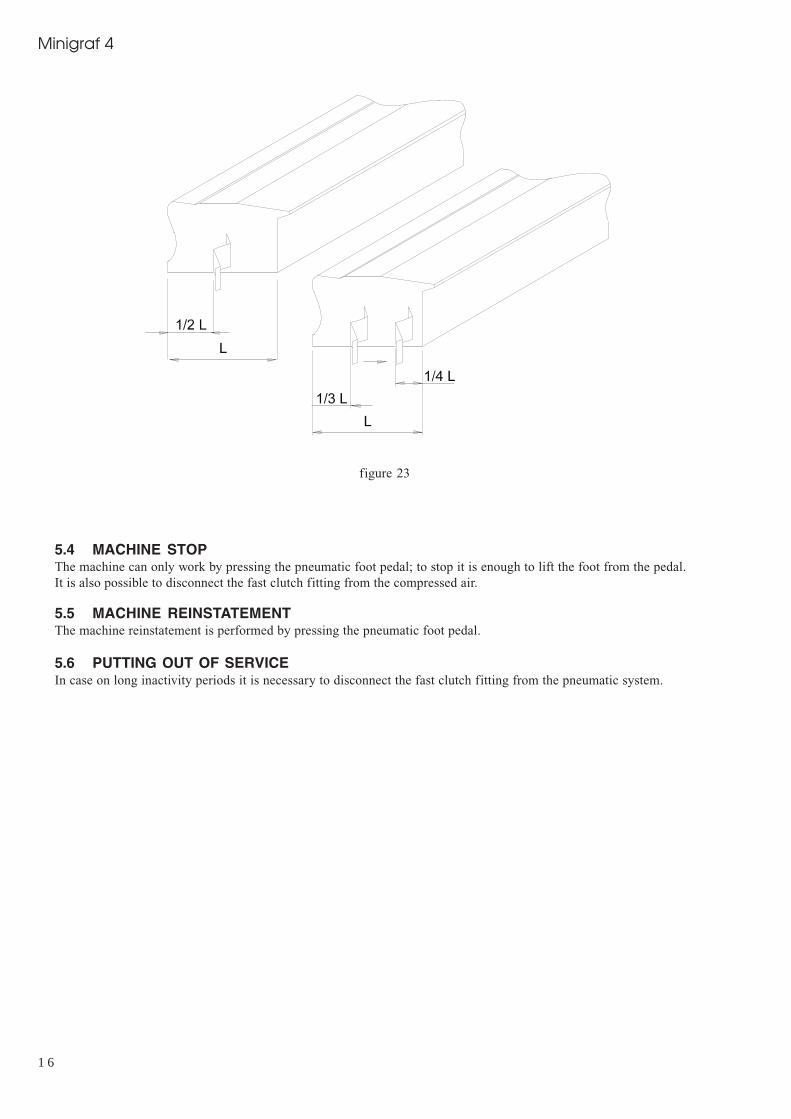
b) Assembling positionsIt is advisable to operate as follows in order to achieve thebest results in terms of junction quality:
Never drive V-nails near the junction vertex. Theminimum recommended distance from the externalvertex is at least 10 mm.When you want to make the junction using only one V-nail, the most suitable position is in the middle of themoulding (see fig. 23)In case you want to insert 2 or more V-nails into eachjunction, we recommend you to insert the most externalone 1/3 from the external vertex and the most internalone 1/4 from the internal vertex.
6. Press half way down on the foot pedal and verify theproper positioning and clamping of the mouldings
7. Press the foot pedal full down to insert the V-nail (if themouldings profile needs 2 or more V-nails stacked inthe same position, release the foot pedal halfway andthen press it again to insert the 2nd V-nail and so on)
8. Release the pedal halfway9. Press the lateral lever halfway to position the V-nail
ejection group in the next inserting point10. Press the foot pedal full down to insert the V-nail (see step 7)11. Release the pedal halfway12. Press the lateral lever all the way down so the driver assembly shifts to the last insertion point13. Press the foot pedal full down to insert the V-nail (see step 7)14. Release the foot pedal completely to release the vertical and the frontal clamps.
1 6
Minigraf 4
figure 23
5.4 MACHINE STOPThe machine can only work by pressing the pneumatic foot pedal; to stop it is enough to lift the foot from the pedal.It is also possible to disconnect the fast clutch fitting from the compressed air.
5.5 MACHINE REINSTATEMENTThe machine reinstatement is performed by pressing the pneumatic foot pedal.
5.6 PUTTING OUT OF SERVICEIn case on long inactivity periods it is necessary to disconnect the fast clutch fitting from the pneumatic system.

1 7
Minigraf 4
Unsuitable lubricants may cause valveseal problems (seals may become toolarge) and consequent Valve jamming.
6. MAINTENANCE
6.1 STATE OF MAINTENANCEThe maintenance operations must be performed with themachine in the conditions described at the “state of themachine” in the tables 6.6.A and 6.7.A
6.2 MACHINE ISOLATIONBefore performing any type of maintenance or repair , it isnecessary to isolate the machine from the followingsupplying sources:1) Disconnect the fast clutch fitting from the pneumatic
system.Once you have finished the maintenance intervention &before reconnecting the pneumatic supply, make sure thatany & all components and any pneumatic connections areproperly reinstalled.
6.3 SPECIAL PRECAUTIONSDuring the maintenance or repair operations is suggestedto proceed as follows:• Before starting any operation place a sign “machine
under maintenance” in a highly visible position• Do not use solvents or flammable materials• Do not step on the machine parts, because they have
not been manufactured to sustain the weight of people.• Once all the operations are f inished, reinstall the
protections or shields you removed or opened
6.4 CLEANINGThe machine structure is simple and robust therefore themechanical parts do not require any special maintenance.It is advisable to follow the rules listed below:• Regularly remove glue or other residues from the V-
nail head and from the upper part of the driver blade;• Always keep the V-nail magazine clean• Remove any residue from the V-nail guide “L” shaped
support.
Do not use water to clean the machine, otherwise the metalparts may rust.
Before performing any cleaningintervention, the operator must disconnectthe pneumatic system..
6.5 LUBRICATIONPreferably CASTROL MAGNA GC 32 or equivalent oilFurthermore, we recommend you lubricate the driver bladeevery 200 working hours.
6.6 ORDINARY MAINTENANCEThe following operations must be executed at the timesindicated below. Not observing the following instructionsexonerate the Producer from any responsibility regardingthe warranty.The operations described below, even if simple, must beexecuted by qualified personnel.The ordinary scheduled maintenance includes overhauls,checks and interventions that will help prevent stops andbreakdowns.• Lubrication state of the machine• Wear and tear parts state

1 8
Minigraf 4
Table 6.6.A - Ordinary Maintenance
Maintenance
V-nail driver blade
Movable parts lubrication
V-nail claw heads
“L” shaped supports (V-nail guide)
Description
Replacement every 1.000.000 V-nails shot
Lubricate the driver blade every 200working hours
Replacement every 5.000.000 V-nails shot
Replacement every 5.000.000 V-nails shot
Machine state
Isolation for maintenance
Isolation for maintenance
Isolation for maintenance
Isolation for maintenance
6.7 EXTRAORDINARY MAINTENANCEListed below are the operations that need the intervention of ALFAMACCHINE , your distributors Technical Assistance (seethe paragraph 1.2) or by qualified staff authorized by the ProducerThe extraordinary maintenance includes interventions to be performed in exceptional cases:• Breakage• Revisions
MAINTENANCE
Valves and Reducers
Frontal and vertical clamp gaskets
DESCRIPTION
Suggested replacement every 6/8 millionof V-nails shot
Replacement in case of air leaks
MACHINE STATE
Isolation for maintenance
Isolation for maintenance
TAB. 6.7 A

1 9
Minigraf 4
7. DIAGNOSTIC7.1 SAFETY WARNINGSThe interventions must be performed by personnel properly trained and must take all precautions in order to avoid accidentalstarts.
7.2 TROUBLESHOOTING
TROUBLE
Pressing the foot pedal the V-nailejection is irregular
Pressing the foot pedal the V-nailejection is irregular
Pressing the foot pedal the V-nailejection is irregular
Pressing the foot pedal the V-nailejection is irregular
Pressing the foot pedal the V-nailejection is irregular
Pressing the foot pedal the V-nailejection is irregular
Pressing the foot pedal the V-nailejection is irregular
Pressing the foot pedal the V-nailejection is irregular
Pressing the foot pedal the V-nailejection is irregular
Pressing the foot pedal for several timesthe machine’s working that was correctat the beginning becomes irregular later
Pressing the foot pedal the workingpressure indicated on the regulatordeeply decreases
Pressing the foot pedal the workingpressure indicated on the regulatordeeply decreases
POSSIBLE CAUSE
Insufficient working pressure
V-nails placed wrong in themagazine
Guide channels damaged orjammed
Claw pusher has insufficientthrust
Claw head not suitable with V-nails size
Faulty V-nails
Insufficient working pressure
Opened V-nail magazine
Faulty valves
Jammed valves because ofsurplus of oil or condensation
Faulty pressure regulator
Feeding pipe too long or ofinadequate diameter
REMEDY
Check that the minimum value indicatedfrom the main regulator is higher than 3Bar
- Check that the V-nails glue side faces up- Check that V-nails V vertex is pointing toward machine’s external side-Defective nails- replace them
- Check that the guide channels are not dirty or jammed
Check that the pressure on the clawpusher cylinder is at least 2 Bar. Ifnecessary, increase it by 10%.Check that the number engraved on thev-nail claw head matchs up to the V-nailssize
- Replace the V-nails- Use shorter sticks of V-nails
Check that the air pressure coming outfrom the compressor is at least 3 Bars.
Close the magazine by means of thespecial lever
- Replace the foot pedal valve
- Replace the control valves
-Remove the surplus of oil andcondensation from the valves bydisconnecting one by one the controlpipes -making the oil/water come outwith the air
-Replace the regulator
Replace the piping with a new one ofbigger diameter
TABLE 7. 2 - A

2 0
Minigraf 4
TROUBLE
Pressing the foot pedal the machineworks properly, but once the pedal isreleased you can note a certain delay inre-positioning of driver blade and/orvertical clamp cylinders
Wishing to insert several V-nails oneupon the other in the same point, theydo not stack properly or tilt during theirinsertion
Wishing to insert several V-nails oneupon the other in the same point, theydo not stack properly or tilt during theirinsertion
Wishing to insert several V-nails oneupon the other in the same point, theydo not stack properly or tilt during theirinsertion
Wishing to insert several V-nails oneupon the other in the same point, theydo not stack properly or tilt during theirinsertion
POSSIBLE CAUSE
Faulty or jammed valves
Unsuitable V-nails
Poor frames clamping (the framemoves during the V-nailinsertion)
Worn driver blade
Jammed driver blade
REMEDY
- Remove the surplus of oil and/ or condensation- Replace the foot pedal valve- Replace the faulty control valves
Replace the V-nails with suitable ones- Check and in possibly replace thevertical and frontal clamping positions
- Increase the pressure by using the regulator- Replace the pressure pad with the proper one
Replace the driver blade
Clean the driver blades upper partremoving any material jamming theupper profile
7.3 REQUEST OF ASSISTANCEFor any information regarding Use, Maintenance, Installation, etc.. we remain at your disposal. The Customer can send adetailed fax describing the problems encountered. For eventual explanations we suggest you use this handbook and theinstructions listed in the paragraph 1.2. as a reference.
E_Mail: [email protected]
FAX: +39 0543 480770
via Dell’Artigiano, 12 - 47100 Forlì - Italy

2 1
Minigraf 4
8. SPARE PARTS
8.1 SPARE PARTS LISTEven though the machine has been submitted to several tests and functional checks, we have listed below the componentsthat we suggest you to have to guarantee the minimum possible downtime.
TABLE 8.1 - A
COMPONENT
• V-NAIL DRIVER BLADE• V-NAIL CLAW HEADS• “L”SHAPED SUPPORT (V-NAIL GUIDE)• VALVES-REDUCERS-REGULATORS• VERTICAL AND HORIZONTAL CLAMPING
GASKETS
8.2 SPARE PARTS ORDERINGWe remind you that only a qualified technician can repair the machine.Thus, we suggest the intervention of ALFAMACCHINE’s or your local distributor’s Center of Technical Assistance, which isdisposable with qualified staff, proper equipment and tools, and with original spare parts.To order the above listed spare parts, send by fax or letter with the following data:• Model of the Machine• Code of exploded parts drawing• Reference number of spare part or group indicated on the mechanic drawing• Code number of single or group spare part
9 DEMOLITION
9.1 DEMOLITIONIn the act of demolition it is necessary to separate the parts in plastic material from components. Depending upon the Normsin the country you live in, you might have to seperate it.Concerning the machine’s metallic mass, it is enough to subdivide the steel parts and those of other metals or alloys, for aproper recycling by smelting.
10. ATTACHMENTS
10.1 DECLARATIONSYou can find attached here the following declarations• Declaration of conformity to the Norm 89/392/CEE
10.2 SCHEMESYou can find attached here the following schemes:• (A) Mechanic Schemes• (B) Pneumatic Scheme• (C) Plates location• (D) Sharpening Table

1Alfamacchine
Minigraf M4 series

2 3
Minigraf 4
Ref. Description
1 Handle2 Washer3 Headless screw4 Screw5 Handle6 Support7 Support8 Rod9 Pressure plate10 Screw11 Handle12 Washer13 Index14 Pressure gauge15 Screw16 Extension17 Pressure regulator18 Lever19 STG valve pushbutton20 Right inch rule21 Knob22 Washer23 Complete connecting plate24 Main frame25 Screw26 Washer27 Support28 Blocking clamp29 Screw30 Screw31 Knob32 Screw33 Lever-valve34 Left inch rule35 Head36 Gasket kit37 Piston38 Cylinder39 Bottom40 Complete cylinder41 Screw42 Slide43 Support44 Screw45 Screw46 Head47 Head48 Piston49 Gasket kit50 Complete cylinder51 Cylinder52 Screw53 Bracket54 Knob55 Support56 Knob57 Spacer58 Protection
59 Valve60 Protection unit61 Support

2 Alfamacchine
Minigraf M4 series

2 5
Minigraf 4
62 Screw63 Spacer64 Support64 Support64 Headless screw65 Slide66 Support67 Bushing67 Bushing67 Pin68 Spring69 Block70 Complete limit stop71 Washer72 Grower73 Nut74 Block75 Support76 Stud77 Spacer78 Screw79 Limit stop80 Complete limit stop82 Screw83 Complete support84 Complete cylinder86 Washer87 Screw88 Complete pin89 Stapples pusher90 Complete head91 Staples box92 Screw93 Head H793 Head H1093 Head H1594 Screw95 L block96 Head97 Block98 Bracket99 Gasket kit100 Piston and driver blade101 Cylinder102 Head103 Pin with clip104 Gasket105 Head106 Rod107 Piston108 Cylinder109 Bottom110 Complete cylinder111 Screw112 Hose113 Raccord114 Screw115 Complete cylinder116 Handle117 Handle
118 Plate119 Support120 Complete hydraulic blocking121 Slide122 Headless screw123 Screw124 Extension125 Washer126 Extension

7Alfamacchine
Minigraf M4 series

2 7
Minigraf 4
Ref. Description
1 Handle2 Washer3 Headless screw4 Screw5 Handle6 Support7 Support8 Rod9 Pressure plate10 Screw11 Handle12 Washer13 Index14 Pressure gauge15 Pressure regulator16 Extension17 Screw18 Screw19 Valve20 Lever21 Inch rule “Z” axis22 Inch rule “Y” axis23 Knob24 Washer25 Complete connecting plate26 Main frame27 Screw28 Washer29 Support30 Blocking clamp31 Screw32 Knob33 Screw34 Lever-valve35 Inch rule “X” axis36 Block37 Head38 Gasket kit39 Piston40 Complete cylinder41 Cylinder42 Bottom43 Screw44 Slide45 Support46 Screw47 Screw48 Head49 Head50 Complete cylinder51 Piston52 Gasket kit53 Cylinder54 Screw55 Bracket56 Knob57 Support58 Knob
59 Spacer60 Protection unit61 Protection62 Valve63 Support

8 Alfamacchine
Minigraf M4 series

2 9
Minigraf 4
64 Screw65 Bushing65 Bushing65 Stud66 Spring67 Block68 Washer69 Grower70 Complete limit stop71 Nut72 Washer73 Screw74 Screw75 Washer76 Screw77 Spacer78 Support79 Bushing80 Complete cylinder 3"’ position81 Screw82 Gasket83 Head84 Rod85 Bushing86 Rod87 Headless screw88 Support89 Screw90 Complete limit stop91 Screw92 Spacer93 Stud94 Support95 Block96 Slide97 Spacer98 Support98 Support98 Headless screw100 Complete head101 Screw102 Support103 Complete cylinder105 Screw106 Complete pin107 Stapples pusher108 Staples box109 Screw110 Head H7110 Head H10110 Head H15111 Screw112 Block “L”113 Head114 Block115 Support116 Gasket kit117 Piston and driver blade118 Cylinder119 Head
120 Complete cylinder121 Pin with clip122 Gasket kit123 Head124 Rod125 Piston126 Cylinder127 Bottom128 Screw129 Hose130 Complete hydraulic blocking131 Raccord132 Screw133 Complete cylinder134 Handle135 Handle136 Plate137 Support138 Slide139 Headless screw140 Screw141 Extension142 Washer143 Extension

Pos. Code Descriptions
11 258210350 Valvola 0ALF 106.A Valve 0ALF 106.A
1A 732440003 Valvola 858/2.52.1.6 Valve 858/2.52.1.6
1B 732440003 Valvola 858/2.52.1.6 Valve 858/2.52.1.6
1C 732440003 Valvola 858/2.52.1.6 Valve 858/2.52.1.6
2 735630007 Regolatore di Pressione 1/8 02 Pressure Regulator 1/8 08
3 735130003 Freno 1/8 “RFU” Flow control 1/8 “RFU”
4 735130006 Bloccaggio Soffice (BIT 02) Soft Clamp (BIT 02)
5 258710011 Pedale 2 Vie Foot pedal
6 258210130 Valvola 0ALF 101 Valve 0ALF 101
7 735630002 Regolatore di Pressione Pressure Regulator
8 258310010 Manometro Manometer
9 258210010 Valvola a Leva 0ALF 100 Lever-Valve

Pos. Code Descriptions
1A 732440003 Valvola 858/2.52.1.6 Valve 858/2.52.1.6
1B 732440003 Valvola 858/2.52.1.6 Valve 858/2.52.1.6
1C 732440003 Valvola 858/2.52.1.6 Valve 858/2.52.1.6
1D 732440003 Valvola 858/2.52.1.6 Valve 858/2.52.1.6
1E 732440003 Valvola 858/2.52.1.6 Valve 858/2.52.1.6
2 735630002 Regolatore di Pressione Pressure Regulator
3 735630007 Regolatore di Pressione 1/8 02 Pressure Regulator 1/8 08
4 735130006 Bloccaggio Soffice (BIT 02) Soft Clamp (BIT 02)
5 258710010 Pedale pneumatico Pneumatic foot pedal
6 732290002 Valvola 0ALF 104.A Valve 0ALF 104.A
7 735630002 Regolatore di Pressione Pressure Regulator
8 258310010 Manometro Manometer
9 258210010 Valvola a Leva 0ALF 100 Lever-Valve
10 258210350 Valvola 0ALF 106.A Valve 0ALF 106.A

3 1
Minigraf 4
SCHEMES C - Plates location

3 2
Minigraf 4
SCHEMES D - Sharpening Table
SW Suitable for soft wood such as: Thailand and Asian South-East wood, Cedar, Pine, Bass, Banak, Obeche, PoplarOther materials: Cellular, Polystyrene, Vertical Grain MDF
SW Suitable for soft wood such as: Thailand and Asian South-East wood, Cedar, Pine, Bass, Banak, Obeche, PoplarOther materials: Vertical Grain MDF
MW Suitable for soft wood such as: Cedar, Cherry, Oak, Ramin, Poplar, Maple, PineOther materials: Vertical grain MDF, Polystyrene, PVC
HW Suitable for soft wood such as: Oak, Ash, Hickory, Pecan, Maple, Cherry, RaminOther materials: Horizontal grain MDF
SOFT WOOD HARD WOOD
A B C D E F
Heightmm
H 3* mm
H 5* mm
H 7 mm
H 10 mm
H 12 mm
H 15 mm
Very softwwod
<>
MW
SW
SW
SW
SW
Soft wood
<>
MW
SW
SW
SW
SW
Averagedsoft wood
<>
MW
MW
MW
MW
MW
Averaged hardwood
MW
MW
MW
MW
HW
HW
Hard wood
MW
MW
HW
HW
HW
HW
Very hardwood
MW
MW
HW
HW
HW
HW
In order to stack 2 or more V-nails per junction, use V-nails coded MW or lower.