miniaturized fuel cell systems: challenges and chances · miniaturized fuel cell systems:...
TRANSCRIPT

Symposium: Advances in Ceramic Science and Engineering, ETH Zurich, September 5, 2008
Miniaturized Fuel Cell Systems: Challenges and Chances
Anja Bieberle-HütterNonmetallic Inorganic Materials ETH Z rich S it erlandNonmetallic Inorganic Materials, ETH Zurich, Switzerland
[email protected], Nonmetallic Inorganic Materials
Outline
A) Miniaturized Fuel Cell Systems in GeneralA) Miniaturized Fuel Cell Systems in General
B) Example: ONEBAT Micro-Solid Oxide Fuel Cell System
[email protected], Nonmetallic Inorganic Materials
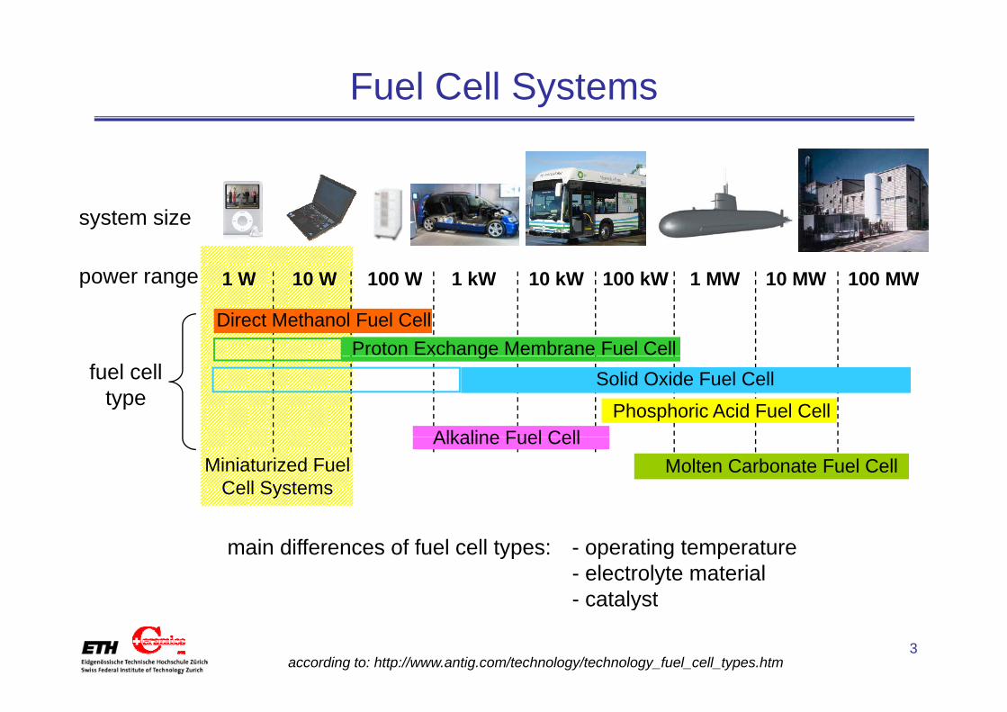
Fuel Cell Systems
power range 1 W 10 kW10 W 100 W 1 kW 100 MW1 MW100 kW 10 MW
system size
power range 1 W 10 kW10 W 100 W 1 kW 100 MW1 MW100 kW 10 MW
Direct Methanol Fuel CellProton Exchange Membrane Fuel Cellg
Solid Oxide Fuel Cell
Phosphoric Acid Fuel CellAlkaline Fuel Cell
fuel cell type
Molten Carbonate Fuel CellAlkaline Fuel Cell
Miniaturized Fuel Cell Systems
main differences of fuel cell types: - operating temperature- electrolyte material
catalyst
[email protected], Nonmetallic Inorganic Materialsaccording to: http://www.antig.com/technology/technology_fuel_cell_types.htm
- catalyst
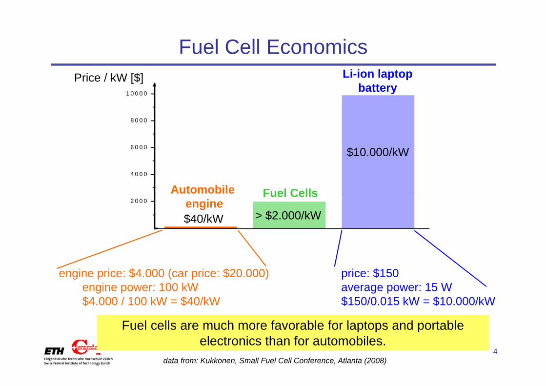
Fuel Cell Economics
1 0 0 0 0
Li-ion laptop battery
Price / kW [$]
6 0 0 0
8 0 0 0
$10 000/kW
4 0 0 0
Automobile Fuel Cells
$10.000/kW
2 0 0 0
$40/kW
Automobile engine
Fuel Cells
> $2.000/kW
engine price: $4.000 (car price: $20.000) price: $150engine power: 100 kW$4.000 / 100 kW = $40/kW
average power: 15 W$150/0.015 kW = $10.000/kW
Fuel cells are much more favorable for laptops and portable
[email protected], Nonmetallic Inorganic Materials
Fuel cells are much more favorable for laptops and portable electronics than for automobiles.
data from: Kukkonen, Small Fuel Cell Conference, Atlanta (2008)
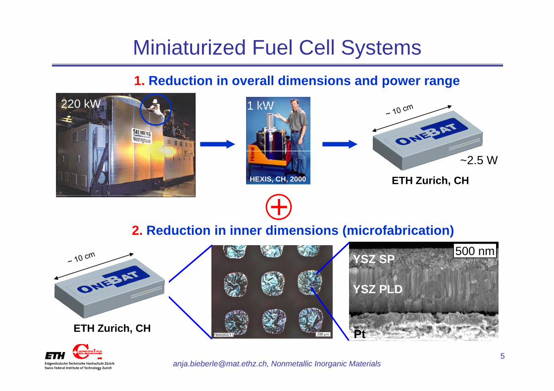
Miniaturized Fuel Cell Systems1. Reduction in overall dimensions and power range
220 kW 1 kW220 kW 1 kW
HEXIS, CH, 2000 ETH Zurich, CH
~2.5 W
2. Reduction in inner dimensions (microfabrication)+
YSZ SP 500 nm
YSZ PLD
ETH Zurich CH
[email protected], Nonmetallic Inorganic Materials
PtETH Zurich, CH
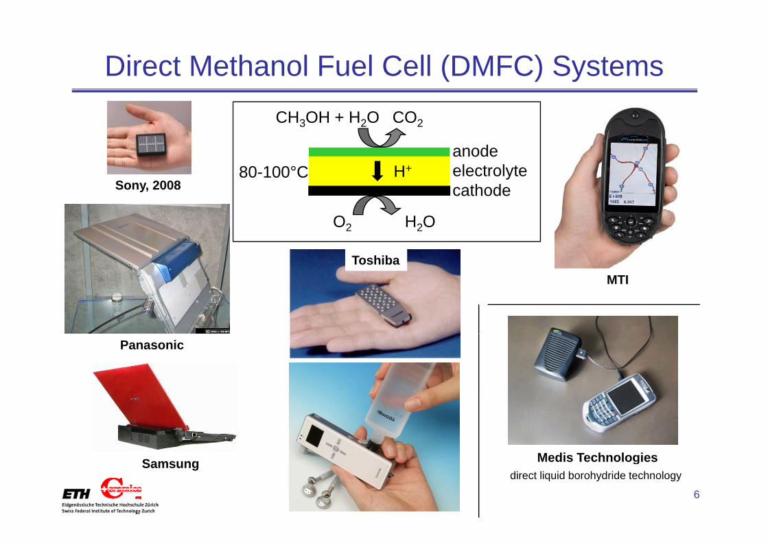
Direct Methanol Fuel Cell (DMFC) Systems
anode
CH3OH + H2O CO2
Sony, 2008
anodeelectrolytecathode
H+80-100°C
O2 H2O
ToshibaMTI
Panasonic
Medis Technologies
[email protected], Nonmetallic Inorganic Materials
Medis Technologiesdirect liquid borohydride technology
Samsung

Proton Exchange Membrane (PEM) Systems
anode
H2 + H2O80-100°C
anodeelectrolytecathode
H+
Motorola / Angstrom MyFC FraunhoferInstitute for Solar
O2 H2O
Institute for Solar Energy Systems (ISE)
Jan 2008:Jan. 2008: fuel cell powered cell phone:• same size• 2x talk-time • refueling in minutes
• charger for portable electronics• April 08: prototype introduced
[email protected], Nonmetallic Inorganic Materials
• refueling in minutes

Solid Oxide Fuel Cell (SOFC) SystemsBieberle-Hütter et al., J. Pow. Sour. 2008
d
C4H10 H2O>350°C
Boston USA ETH Zurich CH
Muecke et al., Adv.Funct. Mat. 2008in press
anodeelectrolytecathode
O2-
Boston, USA ETH Zurich, CH in press
O2
Caltec,
MIT, USA, TullerStandford, USA, Prinz
AIST, J, Suzuki
Nikbin The Fuel Cell ReviewBaertsch et al
[email protected], Nonmetallic Inorganic Materials
USA, HaileShao et al., Nature 2005
Nikbin, The Fuel Cell Review2006
Jasinski, Microelectronics Intern.2008
Huang et al. J. Electrochem. Soc. 2007
Baertsch et al. J. Mat. Res. 2004
Bieberle-Hütter et al.J. Electroceramics 2006

Advantages / Disadvantages of Fuel Cell Types
DMFCPEM DMFCPEM• Top80-100°C most developed so far80-100°C• kind of fuel
l i l
μSOFCμPEM
pure hydrogenreforming required
handling and storage
methanol (CH3OH)toxicity • energy density
• catalyst materialμDMFC
SOFC
Pt
• no tolerance to contaminants• complex heat and water
Pt
• methanol crossover• not suited for extremeSOFCcomplex heat and water
management• not suited for extreme environments
350-550°C
butane, propane
diverse materials feasible, “ ti ” t i l
[email protected], Nonmetallic Inorganic Materials
“exotic” materials
Manhattan Scientifics & L. Livermore National Laboratories and Sulzer Hexis, 2002Rey-Mermet, PhD Thesis, 2008

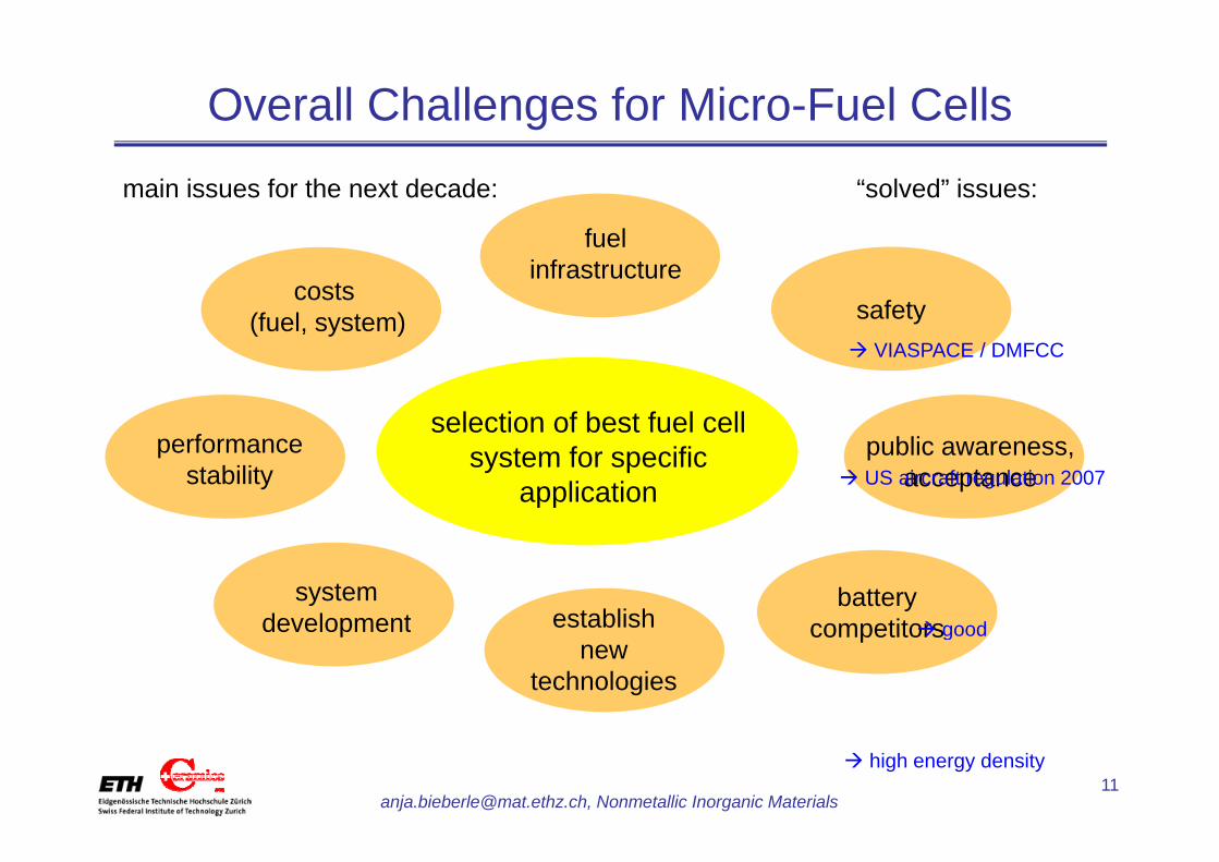
Overall Challenges for Micro-Fuel Cells
fuel
“solved” issues:main issues for the next decade:
fuelinfrastructure
safetycosts
(fuel, system)( , y )
selection of best fuel cell
VIASPACE / DMFCC
public awareness, acceptance
performance stability
selection of best fuel cell system for specific
application US aircraft regulation 2007
battery competitorsestablish
system development goodcompetitorsestablish
new technologies
development good
[email protected], Nonmetallic Inorganic Materials
high energy density

Chances for Micro-Fuel Cells
• many feasible applications
• long runtimeg
• geographical independence• geographical independence
• no charging time, easy charging
• huge and existing marketsNanomarkets Research Report: Micro Power Sources 2005
annual average growth rate for μFC (2006 11): 50 90%
[email protected], Nonmetallic Inorganic Materials
annual average growth rate for μFC (2006-11): 50-90%Innovative Research and Products Inc. (iRAP), Stamford, Conn (2006).
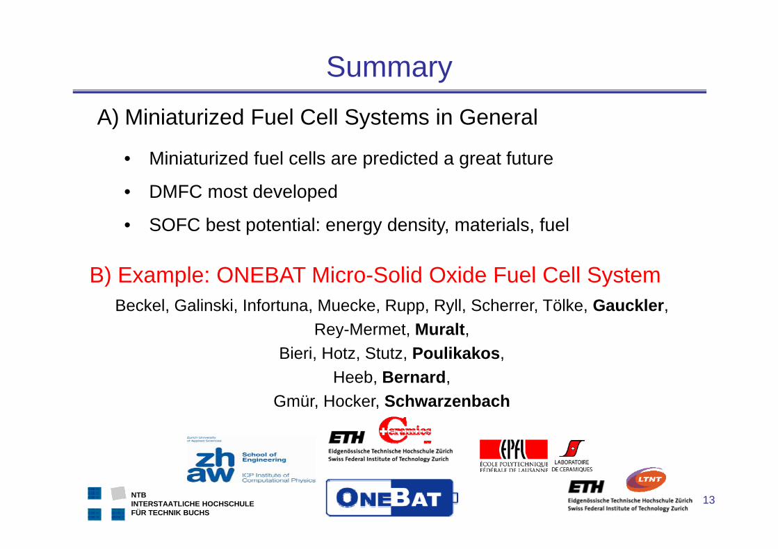
SummaryA) Miniaturized Fuel Cell Systems in General
• Miniaturized fuel cells are predicted a great future
• DMFC most developed
• SOFC best potential: energy density, materials, fuel
B) Example: ONEBAT Micro Solid Oxide Fuel Cell SystemBeckel, Galinski, Infortuna, Muecke, Rupp, Ryll, Scherrer, Tölke, Gauckler,
Rey-Mermet, Muralt,
B) Example: ONEBAT Micro-Solid Oxide Fuel Cell System
y , ,Bieri, Hotz, Stutz, Poulikakos,
Heeb, Bernard, Gmür Hocker SchwarzenbachGmür, Hocker, Schwarzenbach
[email protected], Nonmetallic Inorganic Materials
NTBINTERSTAATLICHE HOCHSCHULEFÜR TECHNIK BUCHS
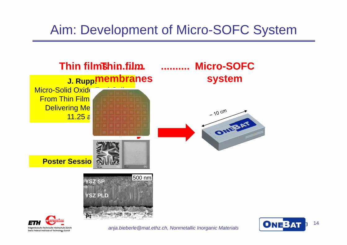
Aim: Development of Micro-SOFC System
Thin filmsThin film Micro-SOFCThin films ..........J. Rupp:
Micro-Solid Oxide Fuel Cells:
Thin film ..........membranes
Micro-SOFC system
From Thin Films to Power Delivering Membranes
11.25 am
Poster Session!!
500 nm500 nmYSZ SP
YSZ PLD
500 nmYSZ SP
YSZ PLD
500 nm
[email protected], Nonmetallic Inorganic Materials
PtPt
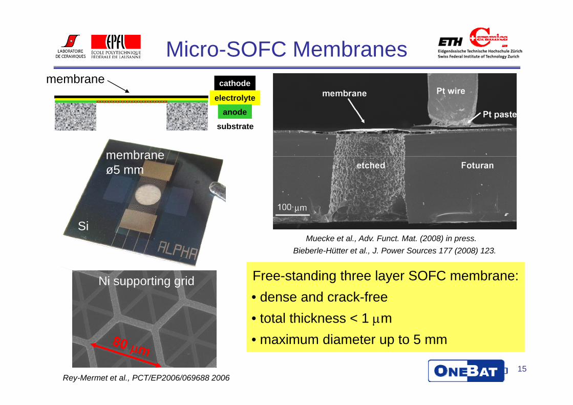
Micro-SOFC Membranesmembrane cathode
electrolyteanode
xxxxxxxxxxxxxxxxxxxxxxxxxxx
membrane
anode
substrate
membrane ø5 mm
Bi b l Hütt t l J P S 177 (2008) 123Muecke et al., Adv. Funct. Mat. (2008) in press.
Si
Ni supporting grid
Bieberle-Hütter et al., J. Power Sources 177 (2008) 123.
Free-standing three layer SOFC membrane: dense and crack free• dense and crack-free
• total thickness < 1 μm• maximum diameter up to 5 mm
[email protected], Nonmetallic Inorganic MaterialsRey-Mermet et al., PCT/EP2006/069688 2006
• maximum diameter up to 5 mm

Micro-SOFC Performance
YSZ PLD/YSZ SP bi-layer electrolyte cellYSZ PLD
Pt (paste)YSZ SP
1.25 200Pt (sputtered)
1.00
550°C500°C450°C
150
powe
⎟⎟⎠
⎞⎜⎜⎝
⎛=
)()(ln
2
2
OpOp
nFRTOCV
a
c
0.75
olta
ge [V
]
100
r density [
YSZ SP
YSZ PLD
500 nm
0 25
0.50vo
50
[mW
/cm2]
YSZ PLD
Pt
50_07s_z
0 250 5000
0.25
0
Pt
OCV = 1.06 V, P = 150 mW/cm2 @ 550°C
0 250 500current density [mA/cm2]
Huang et al. J. Electrochem. Soc. (2007).
400 mW/cm2 / membrane at 400°C280 mW/cm2 / membrane at 350°C
[email protected], Nonmetallic Inorganic Materials
OCV 1.06 V, P 150 mW/cm @ 550 CPmax = 238 mW/cm2 @ 550°C
Muecke et al., Adv. Funct. Mat. (2008) in press.
Shim et al. Chem. Mater. (2007).
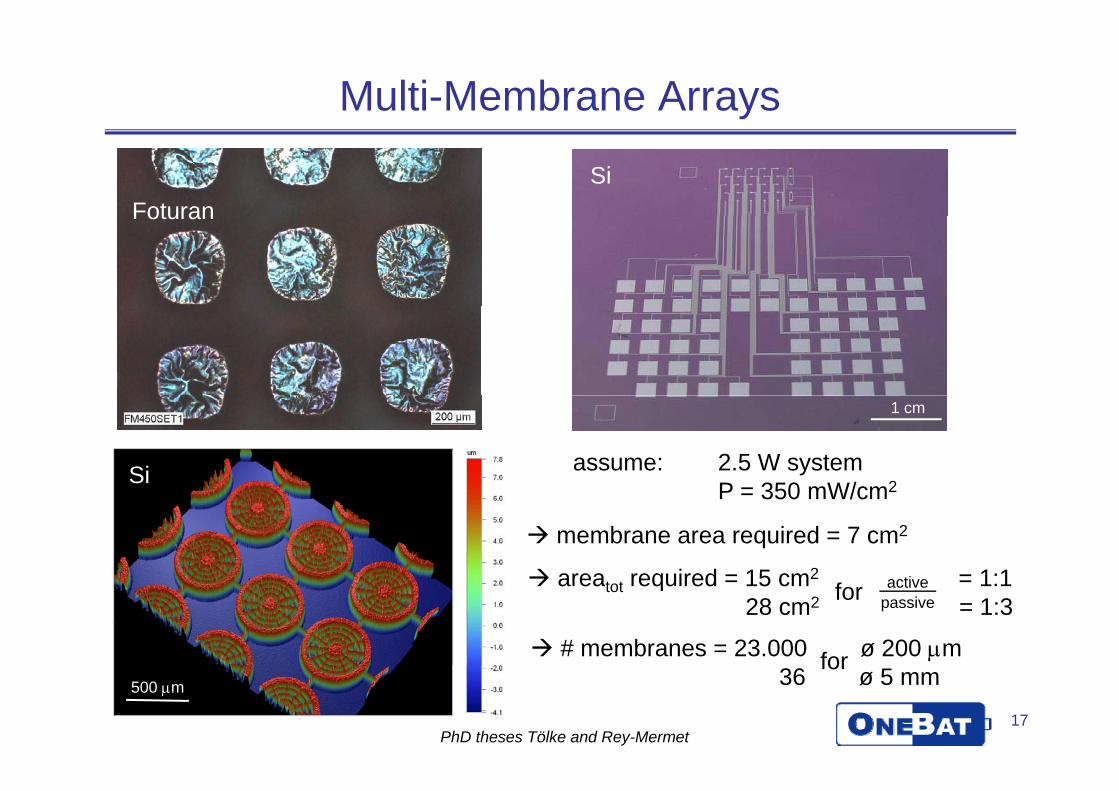
Multi-Membrane Arrays
FoturanSi
Foturan
Si assume: 2.5 W systemP 350 W/ 2
1 cm
P = 350 mW/cm2
area required = 15 cm2 = 1:1
membrane area required = 7 cm2
# membranes = 23.000 ø 200 μm
areatot required = 15 cm2 = 1:128 cm2 = 1:3
activepassive
for
for
[email protected], Nonmetallic Inorganic Materials
36 ø 5 mm for500 μm
PhD theses Tölke and Rey-Mermet
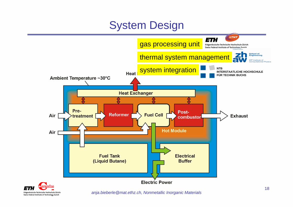
System Designgas processing unit
thermal system managementthermal system management
system integration NTBINTERSTAATLICHE HOCHSCHULEFÜR TECHNIK BUCHS
[email protected], Nonmetallic Inorganic Materials
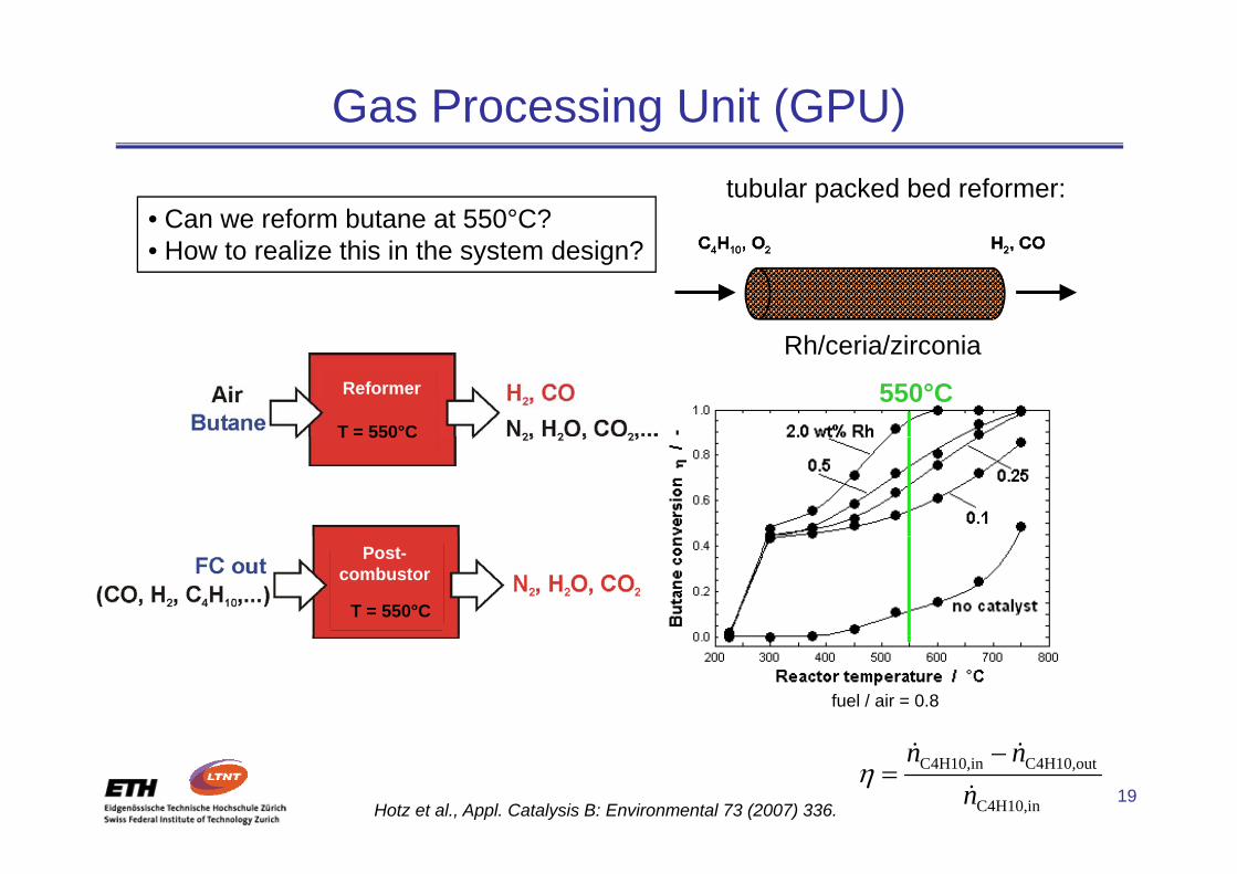
Gas Processing Unit (GPU)tubular packed bed reformer:
• Can we reform butane at 550°C?
Rh/ i / i i
• How to realize this in the system design?
Reformer
T = 550°C
Rh/ceria/zirconia
550°CT 550 C
T = 550°C
Post-combustor
fuel / air = 0.8
[email protected], Nonmetallic Inorganic Materials
C4H10,in C4H10,out
C4H10,in
n nn
η−
=& &
&Hotz et al., Appl. Catalysis B: Environmental 73 (2007) 336.

Microfabricated Si-Structures for GPU
post-combustor top
post-combustor bottomp
11 cm 1 cm
interconnectorreformer bottom
[email protected], Nonmetallic Inorganic Materials
1 cm1 cmNTBINTERSTAATLICHE HOCHSCHULEFÜR TECHNIK BUCHS

Catalytic Activity of Porous Ceramic ReformerButane conversion:
88 – 94 % @ 550°C88 94 % @ 550 C
Hot et al applied for patent (2008)
1 μm
Hotz et al., applied for patent (2008).
• 10 mg catalyst Rh/ceria/zirconia• 10 mg catalyst Rh/ceria/zirconia(2 wt% Rh, 10 nm average diameter)
• 30 mg SiO2 sand(200 μm average diameter)
High catalytic activity at 550°Creactor volume: 37 mm3
exergy content of 2.2 W
[email protected], Nonmetallic Inorganic Materials
gy
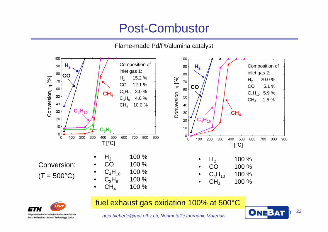
Post-CombustorFlame-made Pd/Pt/alumina catalyst
H C iti fH2
COH2
CO
Composition of inlet gas 1:H2 15.2 % CO 12.1 %C H 3 0 %
Composition of inlet gas 2:H2 20.0 % CO 5.1 %
C4H10
CH4
CH4
C4H10 3.0 % C3H8 4.0 %CH4 10.0 %
C4H10 5.9 % CH4 1.5 %
C3H8
C4H10
Conversion:• H2 100 %• CO 100 %
• H2 100 %• CO 100 %
(T = 500°C) • C4H10 100 %• C3H8 100 %• CH4 100 %
CO 100 %• C4H10 100 %• CH4 100 %
[email protected], Nonmetallic Inorganic Materials
fuel exhaust gas oxidation 100% at 500°C

Component Integration into Hot ModuleReformer Heat
Exchanger 550°C
Membranes35°C
Membranes
Post-Combustor
Fuel
AirExhaustAir
[email protected], Nonmetallic Inorganic Materialsplanar, rectangular, multi-wafer design

Thermal System Management• large temperature gradient of ~ 500°C• uniform stack temperature of 550°C
Main Issues:
• start-up of the system
3D Thermo-Fluidic FE ModelingExperiments 3D Thermo Fluidic FE ModelingExperiments
570 °C400 °C200 °C40 °C
570 C
550°C
good insulation i l i
Temperature gradient of 500°C is feasible.
[email protected], Nonmetallic Inorganic Materials
materials exist
Bieberle-Hütter et al., J. Power Sources 177 (2008) 123.
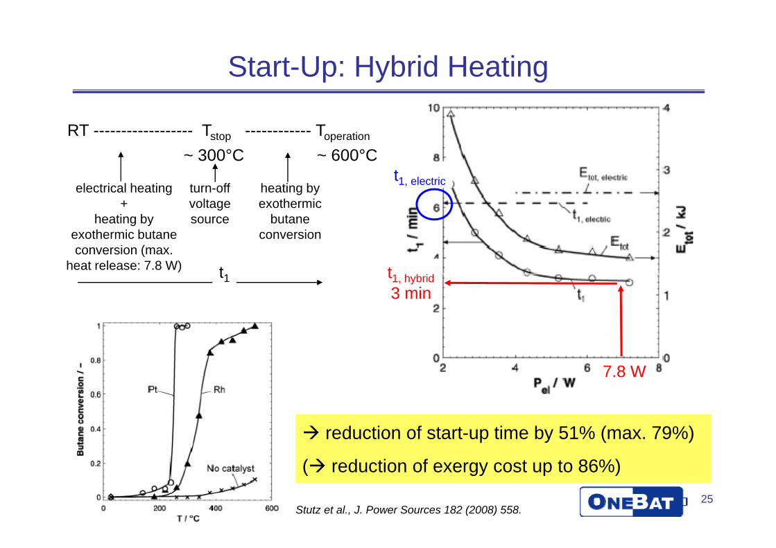
Start-Up: Hybrid Heating
RT ------------------ Tstop ------------ Toperation
300°C 600°Ct1, electricelectrical heating
+ turn-off voltage
heating by exothermic
~ 300°C ~ 600°C
t
heating by exothermic butane conversion (max.
heat release: 7.8 W)
source butane conversion
t13 mint1, hybridt1
7.8 W
reduction of start-up time by 51% (max. 79%)
( d ti f t t 86%)25
[email protected], Nonmetallic Inorganic Materials
( reduction of exergy cost up to 86%)
Stutz et al., J. Power Sources 182 (2008) 558.

System Design
Fuelhot modulestart up
ExhaustAir
insulation
e g supercap
[email protected], Nonmetallic Inorganic Materials
e.g. supercap
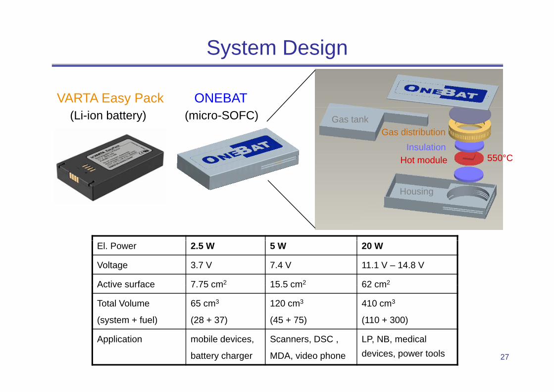
System Design
ONEBATVARTA Easy Pack
Gas distributionInsulation
Gas tank(Li-ion battery) (micro-SOFC)
Hot module
Housing
550°C
g
El. Power 2.5 W 5 W 20 W
Voltage 3.7 V 7.4 V 11.1 V – 14.8 V
Active surface 7 75 cm2 15 5 cm2 62 cm2Active surface 7.75 cm 15.5 cm 62 cm
Total Volume
(system + fuel)
65 cm3
(28 + 37)
120 cm3
(45 + 75)
410 cm3
(110 + 300)
[email protected], Nonmetallic Inorganic Materials
Application mobile devices,
battery charger
Scanners, DSC ,
MDA, video phone
LP, NB, medical devices, power tools

SummaryA) Miniaturized Fuel Cell Systems in General
• Miniaturized fuel cells are predicted a great future
• DMFC most developed
• SOFC best potential: energy density, materials, fuel
B) Example: ONEBAT Micro Solid Oxide Fuel Cell SystemB) Example: ONEBAT Micro-Solid Oxide Fuel Cell System
Fuel Cell System Development
Gas Processing Unit
Thermal System Management
P 238 W/ 2
5 mm free-standing membrane
~80 % butane conversion80-90 % H2 selectivity
at 550°C:550°C inside –35°C outside
manufacturable system design
pgPmax = 238 mW/cm2
at 550°C
standing membrane60-75 % CO selectivity
Poster !!
[email protected], Nonmetallic Inorganic Materials
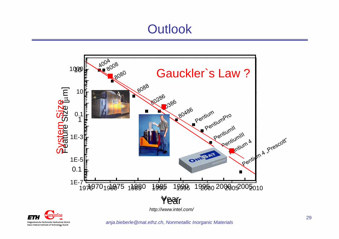
Outlook
M ` L10m
]Moore`s Law
10
1000 Gauckler`s Law ?
1Siz
e [μ
m
0.1
10
Siz
e
1
eatu
re S
1E-3
yste
m
0.1
Fe
1E-5
Sy
1970 1975 1980 1985 1990 1995 2000 2005
Year1975 1980 1985 1990 1995 2000 2005 2010
1E-7
Year29
[email protected], Nonmetallic Inorganic Materials
http://www.intel.com/
YearYear

Thanks to ...
... the ONEBAT consortium for the excellent work !
Federal Office for Professional Education and Technology
Competence Center for Energy and Mobility
Federal Office for Professional Education and Technology
Swiss electricity grid companies
Competence Center for Energy and Mobility
Swiss electricity grid companies
Swiss Federal Office of EnergySwiss Federal Office of Energy
Mikroglas
[email protected], Nonmetallic Inorganic Materials
g