mini-split systems service manual indoor and outdoor unit
TRANSCRIPT

1
MINI-SPLIT SYSTEMS SERVICE MANUAL Indoor and Outdoor Unit Error Codes
and Component DiagnosticCorp1816-L7
10/2020 Supersedes 8/2018
MCFA and MCFB
M22A, M33A andM33B
MMDA and MMDB
MWMA, MWMB and 3WMB036 MPA, MPB and
MLA Single Zone
MPA, MPB and MLAMulti-Zone
Table of Contents1. Outdoor Unit Indicators and Controls ...
.................................................................31.1. Multi-Zone Outdoor Unit Spot Check Function ..31.2. Multi-Zone Outdoor Digital Display ....................51.3. Multi-Zone Error Codes .....................................6
2. Indoor Unit Indicators and Controls .... 72.1. Cassette Unit Display (M22A, M33A & M33B)...72.2. Ducted Unit Display (MMDA & MMDB) ..............8
3. Single Zone - Indoor and Outdoor Error Codes ..................................................... 9
4. Extended Reference Guide - Outdoor Unit Error Codes ...................................114.1. Error Code: E0 .................................................114.2. Error Code: E1 / E2 .........................................124.3. Error Code: E3 .................................................154.4. Error Codes: E4, F1, F2 and F3 ......................174.5. Error Code: E5 .................................................184.6. Error Code: E6 .................................................214.7. Error Code: E8 .................................................234.8. Error Codes: F1, F2, F3, F4 , F5 and F6 .........254.9. Error Code: P1 .................................................26
4.10. Error Code: P2 .................................................284.11. Error Code: P3 .................................................304.12. Error Code: P4 .................................................324.13. Error Code: P5 .................................................334.14. Error Code: P6 .................................................344.15. Error Code: P7 .................................................35
5. Extended Reference Guide - Indoor Unit Error Codes .................................. 365.1. Error Code: CP ................................................365.2. Error Code: E0 .................................................375.3. Error Code: E1 .................................................385.4. Error Code: E3 .................................................415.5. Error Code: E4 .................................................425.6. Error Code: E5 .................................................435.7. Error Code: EC ................................................445.8. Error Code: EE ................................................455.9. Error Code: F0 .................................................465.10. Error Code: F1 .................................................475.11. Error Code: F2 .................................................485.12. Error Code: F3 .................................................495.13. Error Code: F4 .................................................505.14. Error Code: F5 .................................................515.15. Error Code: F6 .................................................52

2
5.16. Error Code: P0 .................................................535.17. Error Code: P1 .................................................555.18. Error Code: P2 .................................................565.19. Error Code: P3 .................................................575.20. Error Code: P4 .................................................575.21. Error Code: P5 .................................................585.22. Error Code: P6 .................................................59
6. Over-Voltage or Under-Voltage Protection Diagnosis and Solution .... 62
7. Temperature Sensor Resistance Values 63
8. Discharge Temperature Sensor Resistance Values ............................... 64
9. TemperatureSensorIdentificationTable ..................................................... 65
10. Component Diagnostics ..................... 6510.1. Compressor Check .........................................6510.2. IPM Check ......................................................6610.3. Fan Motors ......................................................6710.4. Four-Way Valve ..............................................7110.5. EXV Check .....................................................7210.6. Electronic Expansion Valve (EXV) Control .....74
11. Single Zone Error Codes .................... 75

3
WARNINGImproper installation, adjustment, alteration, service or maintenance can cause property damage, personal injury or loss of life.Installation and service must be performed by a licensed professional HVAC installer (or equivalent) or service agency
1. Outdoor Unit Indicators and Controls
1.1. Multi-Zone Outdoor Unit Spot Check FunctionThere is a check switch on the outdoor control board. Push the switch labelled SW1 to check the status of unit when the unit is running. The two-digit display will provide the following status indicators (see table 1) each time the SW1 switch is pushed.
SW1
Figure 1. SW1 Location
Table 1. Status IndicatorsDisplay Remark
0 Normal Display Display running frequency, running state or malfunction code
1 Number of connected indoor units
Actual data
Display Number of indoor units1 one2 two3 three4 four5 five
2 Outdoor unit running mode Off: 0, Fan only: 1, Cooling: 2, Heating: 3, Forced cooling: 4

4
Table 1. Status IndicatorsDisplay Remark
3 Indoor unit A capacity
The capacity unit is horsepower. If the indoor unit is not connected, the digital display tube will show: “――”(9K:1HP,12K:1.2HP,18K:1.5HP)
4 Indoor unit B capacity5 Indoor unit C capacity6 Indoor unit D capacity7 Indoor unit E capacity8 Indoor unit A capacity demand code
Norm code*HP(9K:1HP,12K:1.2HP,18K:1.5HP)
9 Indoor unit B capacity demand code
10 Indoor unit C capacity demand code
11 Indoor unit D capacity demand code12 Indoor unit E capacity demand code13 Outdoor unit amendatory capacity demand code Forced cooling:7
14 The frequency corresponding to the total indoor units amendatory capacity demand
15 The frequency after the frequency limit16 The frequency sending to compressor control chip
17 Indoor unit A evaporator outlet temp.(T2BA)
• If the temperature is lower than -9 degrees, the two-digit display will show “-9”.• If the temperature is higher than 70 degree, the two-digit display will show “70”. • If the indoor unit is not connected, the two-digit display will show: “――”
18 Indoor unit B evaporator outlet temp.(T2BB)19 Indoor unit C evaporator outlet temp.(T2BC)20 Indoor unit D evaporator outlet temp.(T2BD)21 Indoor unit E evaporator outlet temp.(T2BE)22 Indoor unit A room temp.(T1A)
• If the temperature is lower than 0 degree, the two-digit display will show “0”.• If the temperature is higher than 50 degree, the two-digit display will show “50”. • If the indoor unit is not connected, the two-digit display will show: “――”
23 Indoor unit B room temp.(T1B)24 Indoor unit C room temp.(T1C)25 Indoor unit D room temp.(T1D)26 Indoor unit E room temp.(T1E)27 Indoor unit A evaporator temp.(T2A)
• If the temperature is lower than -9 degree, the two-digit display will show “-9”.• If the temperature is higher than 70 degree, the two-digit display will show “70”. • If the indoor unit is not connected, the digital display tube will show: “――”
28 Indoor unit B evaporator temp.(T2B)29 Indoor unit C evaporator temp.(T2C)30 Indoor unit D evaporator temp.(T2D)31 Indoor unit E evaporator temp.(T2E)32 Condenser pipe temp.(T3)
33 Outdoor ambient temp.(T4)
34 Compressor discharge temp.(TP)
• The display value should be between 30 and 129 degrees. • If the temperature is lower than 30 degree, the two-digit display will show “30”.• If the temperature is higher than 99 degree, the two-digit display will show single digit and tens digit.
NOTE: For example, the two-digit display show “0.5”,it means the compressor discharge temp. is 105 degree.)
35 AD value of current The display value is hex number.
NOTE: For example ,the two-digit display show “Cd”, it means AD value is 205.36 AD value of voltage
37 EXV open angle for indoor unit A• Actual data/4.• If the value is higher than 99, the two-digit display will show single digit and tens digit.
NOTE: For example ,the two-digit display show “2.0”,it means the EXV open angle is 120×4=480p.)
38 EXV open angle for indoor unit B39 EXV open angle for indoor unit C40 EXV open angle for indoor unit D41 EXV open angle for indoor unit E

5
Table 1. Status IndicatorsDisplay Remark
42 Frequency limit symbol
Bit7 Frequency limit caused by IGBT radiatorThe display value is a hex number.
NOTE: For example, the digital display tube shows 2A,then Bit5=1, Bit3=1, Bit1=1. It means frequency limit caused by T4, T3 and current.
Bit6 Frequency limit caused by PFCBit5 Frequency limit caused by T4.Bit4 Frequency limit caused by T2.Bit3 Frequency limit caused by T3.Bit2 Frequency limit caused by T5.Bit1 Frequency limit caused by currentBit0 Frequency limit caused by voltage
43 Average value of T2 (Sum T2 value of all indoor units)/( number of indoor units in good connection)44 Outdoor unit fan motor state Off:0, High speed:1, Med speed:2, Low speed:3 Breeze:4, Super breeze:545 The last error or protection code 00 means no malfunction and protection46 Indoor unit F capacity Not used47 Indoor unit F capacity demand code Not used48 Indoor unit F evaporator outlet temp.(T2BF) Not used49 Indoor unit F room temp.(T1F) Not used50 Indoor unit F evaporator temp.(T2F) Not used51 EXV open angle for F indoor unit Not used
1.2. Multi-Zone Outdoor Digital DisplayThere is a two-digit display on the outdoor unit control board. The following are the code descriptions:
Table 2. Multi-Zone Outdoor Unit Error CodesDisplay Code Description
In protection or malfunction, the LED displays error code or protection code.In compressor operation, the LED display the running frequency,
-- Outdoor unit - standby mode for single zone. The LED displays “- -”-- Multi zone mode conflict - - (dash dash) indoor display or operation lamp Flashes 6 times, timer lamp Flashing, - - displaydF In defrosting mode, the LED displays “dF” or alternative displays between running frequency and “dF”(each displays 0.5s)PH In compressor pre-heating, The LED displays “PH” or alternative displays between running frequency and “PH”(each displays 0.5s)RO During the oil return process, The LED displays “RO” or alternative displays between running frequency and “RO”(each displays 0.5s)
LC In low ambient cooling mode, the LED displays “LC” or alternative displays between running frequency and “LC”(each displays 0.5s)FC In forced cooling mode, the LED displays “FC” or alternative displays between running frequency and “FC”(each displays 0.5s)E6 When PFC module protection occurs three times within 15 minutes, the LED displays “E6” or alternative displays between running frequency and “E6”(each displays
0.5s)CP When the LED displays CP, this indicates the J1 jumper removed or loose or the remote on / off switch is activated. CL When the LED displays CL, this is a reminder to check and clean the air filter.NF When the LED displays NF, this indicates 2880 hour filter replacement reminder. To clear press the LED button 5 times within 15 seconds when the CL or NF shows to
reset and clear code.CF CF anti-cold blow. Fan will stay Off on call for heat unit indoor coil warms up to 90°F or above.FP Freeze protection. The silence (FP) button was pushed and held for more than three seconds. Temperature will hold at 46°F until returned to normal operation.

6
1.3. Multi-Zone Error Codes
Table 3. Multi-Zone Outdoor / Indoor Unit Error Codes MatchesDisplay LED Status New Indoor Error
E0 Outdoor unit EEPROM parameter error F4
E2 Communication malfunction between indoor and outdoor units E1
E3 Communication malfunction between IPM board and outdoor main control board ——
E4 Outdoor temperature sensor (coil sensor T3,ambient sensor T4, Compressor discharge sensor T5 indoor coil outlet pipe sensor T2B) malfunction
F2/F1/F3/F6
E5 Over-voltage or under-voltage protection P1
E6 PFC module protection ——
E8 Outdoor fan speed malfunction F5
F1 No. A Indoor unit coil outlet temperature sensor malfunction ——
F2 No. B Indoor unit coil outlet temperature sensor malfunction ——
F3 No. C Indoor unit coil outlet temperature sensor malfunction ——
F4 No. D Indoor unit coil outlet temperature sensor malfunction ——
F5 No. E Indoor unit coil outlet temperature sensor malfunction ——
F6 No. F Indoor unit coil outlet temperature sensor malfunction ——
P1 High pressure protection P6
P2 Low pressure protection P6
P3 Current overload protection F0
P4 Temperature protection of compressor discharge ——
P5 Condenser high temperature protection ——
P6 Inverter module (IPM) malfunction P0
LP Low ambient temperature protection ——
Table 4. Multi-Zone Indoor Unit Error CodesDisplay Error Description
E0 Outdoor unit EEPROM error.E2 Communication error between outdoor unit and all indoor units.E3 Communication error between outdoor unit main control and IPM control.E4 Temperature sensor error (outdoor coil, outdoor ambient , compressor discharge and indoor unit coil outlet temperature sensors.E5 High and low voltage protection.E8 Outdoor DC fan speed error.F1 Indoor unit #1 coil outlet temperature sensor error.F2 Indoor unit #2 coil outlet temperature sensor error.F3 Indoor unit #3 coil outlet temperature sensor error.F4 Indoor unit #4 coil outlet temperature sensor error.F5 Indoor unit #5 coil outlet temperature sensor error.F6 Indoor unit #6 coil outlet temperature sensor error.P1 High pressure switch openP2 Low pressure switch openP3 Outdoor compressor current overload sensed.P4 High temperature sensed at compressor discharge line.P5 High temperature sensed at outdoor coil.P6 Inverter module (IPM) error.

7
2. Indoor Unit Indicators and ControlsFor a list of applicable error codes for the indoor units, refer to “3. Single Zone - Indoor and Outdoor Error Codes” on page 9. All indoor units provide error code information with either a digital LED display or with Flash codes.
2.1. Cassette Unit Display (M22A, M33A & M33B)
M0STAT62Q-1
M0STAT63Q-1
Table 5. Cassette Displays

8
2.2. Ducted Unit Display (MMDA & MMDB)
OPERATION TIMER DEF./FAN ALARM
Temporary button
Operation lamp
Timer indicatorInfrared signal receiver
Alarm indicator
PRE-DEF indicator(cooling and heating type)or fan only indicator(cooling only type)
MANUAL
Display digital
88
Figure 2. Ducted Unit Display
Wall-Mounted (MWMA, MWMB & 3WMB) and Ceiling/Floor (MCFA & MCFB) Unit Displays
Floor / Ceiling UnitWall Unit
Figure 3. Wall-Mounted Unit Display

9
3. Single Zone - Indoor and Outdoor Error CodesTable 6. Single-Zone 009/012 115VAC/208-230VAC
LED Display (LED 1: Blue/Red) Error Description
Slow Flash Standby
On Normal operation
Flash Flash Outdoor unit error.
Slow Flash -- Flashing at 1Hz.Flash Flash - Flashing at 2Hz.
Table 7. Single-Zone 018/030 208-230VACMain Control IPM Control (comp. driver) Error Description
Blue or Yellow LED Red LED Green LED
Slow Flash Off ON Stand-byON ON Off Normal operation
Flash Flash Off ON
Could be one of the following:• Indoor and outdoor unit communication error.• Outdoor unit temperature sensor error.• Outdoor unit EEPROM error• Compressor top temperature switch is open.
Flash Flash ON ON DC bus voltage is too high or to low protection.Flash Flash Flash Flash ON Driver EEPROM error.Flash Flash Flash Flash Off Driver chip start-up failure.
Flash Flash ON Flash Flash
Could be one of the following:• Driver phase loss protection • Driver zero speed protection• PWM synchronization failure.
Flash Flash Off Flash Flash IGBT over-current or IPM over-currentFlash Flash Flash Flash Flash Flash Control chip communication error.
Slow Flash - Flashing at 1Hz and Flash Flash- Flashing at 2Hz
Table 8. Indoor Unit Fault Codes (09K through 36K Wall-Mounted Units)Running Light Short
FlashesState of Timer
LightDisplay Description
1 time Off E0 Indoor unit EEPROM error2 times Off E1 Communication error between indoor and outdoor units (E2 for outdoor code)4 times Off E3 Indoor fan speed error5 times Off E4 Indoor return air temperature sensor error6 times Off E5 Indoor coil temperature sensor error
7 times Off EC Low refrigerant8 times Off EE High water level alarm.1 time ON F0 Outdoor current overload sensed.
Note: (outdoor unit display --) two dashes2 times ON F1 Outdoor ambient temperature sensor error (T4 malfunction) outdoor unit display E43 times ON F2 Outdoor coil temperature sensor error (T3) Malfunction outdoor unit display E44 times ON F3 Compressor discharge temperature sensor error (T5) Malfunction outdoor unit display E45 times ON F4 Outdoor unit EEPROM error - outdoor display E06 times ON F5 Outdoor unit fan speed error - outdoor Error display E81 time Flash P0 Inverter module IPM error - outdoor display P62 times Flash P1 High or low voltage protection - outdoor display E54 times Flash P3 Outdoor unit low temperature lockout - outdoor unit display LP5 times Flash P4 Compressor drive error6 times Flash -- Mode conflict7 times Flash P6 Multi-Zone compressor high- or low-pressure switch open - outdoor unit display P2

10
Table 9. Indoor Unit Fault Codes (09K through 48K Cassette, Ducted and Ceiling/Floor Units)Running Light Short
FlashesState of Timer
LightDisplay Description
1 time Off E0 Indoor unit EEPROM error2 times Off E1 Communication error between indoor and outdoor units (E2 for outdoor code)4 times Off E3 Indoor fan speed error5 times Off E4 Indoor return air temperature sensor error6 times Off E5 Indoor coil temperature sensor error7 times Off EC Low refrigerant8 times Off EE High water level alarm (ducted and cassette units with factory pumps)1 time ON F0 Outdoor current overload sensed Note: (outdoor unit display --) two dashes2 times ON F1 Outdoor ambient temperature sensor error (T4 malfunction) outdoor unit display E43 times ON F2 Outdoor coil temperature sensor error (T3) Malfunction outdoor unit display E44 times ON F3 Compressor discharge temperature sensor error (T5) Malfunction outdoor unit display E45 times ON F4 Outdoor unit EEPROM error - outdoor display E06 times ON F5 Outdoor unit fan speed error - outdoor Error display E81 time Flash P0 Inverter module IPM error - outdoor display P62 times Flash P1 High or low voltage protection - outdoor display E54 times Flash P3 Outdoor unit low temperature lockout - outdoor unit display LP5 times Flash P4 Compressor drive error7 times Flash P6 Mode conflict8 times Flash P7 Multi-Zone compressor high- or low-pressure switch open - outdoor unit display P2

11
4. Extended Reference Guide - Outdoor Unit Error Codes4.1. Error Code: E0Description: Outdoor EEPROM malfunction. General Note: Outdoor unit main control board chip is not receiving feedback from EEPROM chip.
Outdoor EEPROM malfunction
Power off, then restart the unit 3 minutes later.
Yes
Does the problem still exist?
Yes
Replace the outdoor main control board.

12
4.2. Error Code: E1 / E2Description: Communication malfunction between outdoor unit and all indoor units.General Note: Indoor unit is not receiving communication from outdoor unit for 120 seconds, or outdoor unit has
not receive communication from any indoor units for 180 seconds.E2
Start: Power off, then power on the outdoor unit using the breaker (reconnect the power wire). Is it
still displaying the error code?
Check wiring on the outdoor and indoor unit terminals using the unit wiring diagrams. Are
all of the connections correct?
Yes
Yes
Correct the wiringNo
Turn on all indoor units using the provided remote control. Are all indoor units displaying correctly? Is the refrig-
erant charge okay?
No
Measure L2 and L3 as it is alternating between positive and negative values? (Vs is the voltage between L2 and L3).
See photo.
NoIs all the wiring between
terminals and indoor main control board connected
correctly`?
No
No
Reconnect the wiring
Yes
Change the Indoor main control board.
Yes
Power on by remote controller, it is still displaying the error code after
3 minutes?
No
Yes
Turn off all indoor units. Is integrated power module (IPM) power LED operating lamp on?
Refer to Pic 2.
Yes
YesChange IPM
No
Yes
Is the display on? Refer Pic 3.No Is the reactor
wiring properly connected?
No Check wiring and wiring diagram
Yes
Change Outdoor Main ControlYes
Are the indoor units numbered correctly? Check on the outdoor check point. (2 for 2-zone, 3 for 3-zone, 4 for 4-zone, 5 for 5-zone). See Pic 4.
Problem Solved
Change the complete electri-cal box
13
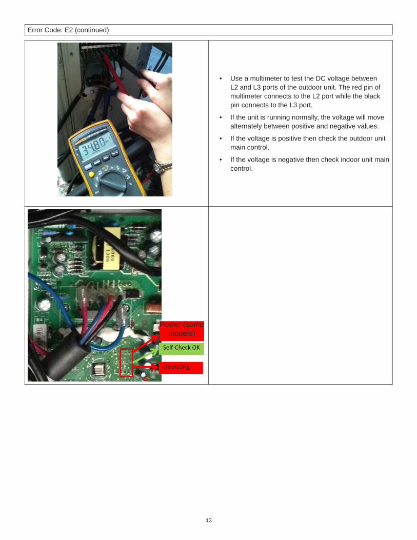
Error Code: E2 (continued)
• Use a multimeter to test the DC voltage between L2 and L3 ports of the outdoor unit. The red pin of multimeter connects to the L2 port while the black pin connects to the L3 port.
• If the unit is running normally, the voltage will move alternately between positive and negative values.
• If the voltage is positive then check the outdoor unit main control.
• If the voltage is negative then check indoor unit main control.
Self-Check OK
Power (some modles)
Opera ng
Power (some models)

14
Error Code: E2 (continued)
Integrated Power Module (IPM) for 2- and 3-zones units.
Main board LED when power is on and unit in standby mode with no error codes.
Check point button, press once to verify the number of indoor units are connected.

15
4.3. Error Code: E3Description: Communication error between outdoor unit main control and integrated power module (IPM).General Note: The main outdoor control board chip is not receiving feedback from integrated power module for a
duration of 60 seconds.
Communication malfunction between integrated power module (IPM) board and
outdoor main board.
Is there at least one LED on the IPM board light?
No
Check the signal wire between the IPM module and the outdoor unit main board.
Is it connected correctly?
No
Reconnect and retry. Is there still an error code being displayed?
Yes
Replace integrated power module (IPM) board, and then check to see if the sys-tem is operating normally. Is it operating
normally?
No
Replace outdoor unit main board, and then check whether the system operates
normally. Is it operating normally?
No
Replace the electric control box.Problem Solved.
Yes
YesNo
Yes
Yes
Yes
Yes

16
Error Code: E3 (continued)
NOTE - Use a multimeter to test the DC voltage between black pin and white pin of signal wire The normal value should be around 5V.Use a multimeter to test the DC voltage between black pin and red pin of signal wire. The normal value should be around 12V.

17
4.4. Error Codes: E4, F1, F2 and F3Description: Temperature sensor error:
T2 indoor unit coil outlet temperature sensorT3 outdoor coil sensorT4 outdoor ambient sensor T5 compressor discharge sensor
General Note: Error displays if voltage is lower than 0.06V or higher than 4.94V.
Check the connections between tempera-ture sensor and outdoor unit main control.
Are the connections good?
Yes
No Correct the connections
Check the resistance value of the applicable sensor.
• See “Table 11. Temperature Sensor Resistance Value Table (°F/°C)” on page 63 for T1-T4.
• See “Table 12. Discharge Temperature Sensor Table (°C--K)” on page 64 for T5.
Yes Replace indoor or out-door main control.Is it normal?
No
Replace the sensor.

18
4.5. Error Code: E5
Description: High or low voltage protection active.General Note: Either an abnormal voltage rise or drop is detected. Check the specified voltage detection circuit.
Voltage protection
Check the voltage of outdoor unit power supply, the voltage between
L1 and L2. Minimum range is 187 to 253VAC max.
Yes
Check whether the voltage of integrated power module (IPM) board P and N is
normal? 277-356VDC for 18-30KBtu/h;
277-410VDC for 36KBtu/h.
No
Replace bridge rectifiers and check verify the system is operating normally. (Only for 4-zone MPA036 and MLA036 units)
No
Replace IPM board, and then checkfor normal unit operation.
No
Replace outdoor unit main board. Problem Solved.
Yes
Yes
Check the primary power supply.No

19
Error Code: E5 (continued)
IPM (for 4-zone)
P-N (for 2-zone and 3-zone)
IPM (for 2-zone and 3-zone)

20
Error Code: E5 (continued)
P-N (for 4-zone)
Bridge rectifier for 2-zone and 3-zone
Bridge rectifier for 4-zone

21
Error Code: E5 (continued)
Remark:
Measure the DC voltage between + and - port
on the bridge rectifier. The normal value should be 190V~250V.
4.6. Error Code: E6Description: Power Factor Correction (PFC) module protection (MPA036S4M-1P and MPA048S4M-1P only)General Note: When the voltage signal sent by the PFC to the main outdoor unit control board is abnormal, the
display LED will show “E6” and unit will turn off.
PFC module protection
Check wire connections between outdoor unit main board and the
PFC module. Is connection good?.
Yes
Verify the voltage range betweenP-N on IPM module is normal? 277-356VDC for 18-30KBtu/h
277-410VDC for 36KBtu/h
No
Verify the inductance of the PFC module is good. If the inductor isgood, the resistance value of the
two ports will be 0.
Yes
Replace the PFC module.Problem Solved.
Yes
Correct faulty connections, then check for proper unit operation
No
Yes
No
Replace the outdoor unit main control board.
No Replace the inductor.

22
Error Code: E6 (continued)
Two terminals of the inductor
Inductor

23
4.7. Error Code: E8Description: Outdoor DC fan motor speed error.General Note: When outdoor fan speed is too low (300 RPM) or too high (2400 RPM) for a specific time duration,
the unit will stop and the LED will display the failure.
E8
Power off outdoor unit and then restart the unit after three minutes. Is it still dis-
playing the error code?
Yes
Shut off the power supply, and inspect all components for damage. Rotate the fan by hand. The Fan should offer little
resistance when manually spun. Does the wheel and shaft should spin evenly and
balanced?
Yes
Check all wiring connections. Are the con-nections good?
Yes
Check that the main outdoor control board is it operating correctly?
The unit operates normally.No
Yes
Use “Table 16. Resistance Value for AC or DC Fan Motors” on page 67 to troubleshoot the fan. Is the fan motor
okay?
Make necessary corrections No
Correct faulty corrections.No
Replace the outdoor unit main control.No

24
Error Code: E8 (continued)NOTE: DC fan motor(control chip is inside fan motor)Power on and while the unit is in standby, measure the voltage between pins 1 and 3. Also measure the voltage between pin 3 and 4 at fan motor connector.If the value of the voltage is not in the range as shown in the below table, the outdoor unit main control board is faulty and should be replaced.
Table 10. DC Motor Voltage Input and OutputNo. Color Signal Voltage
1 Red Vs/Vm 200~380V
2 --- --- ---
3 Black GND 0V
4 White Vcc 13.5~16.5V
5 Yellow Vsp 0~6.5V
6 Blue FG 13.5~16.5V
Vs Vcc
Vsp FG

25
4.8. Error Codes: F1, F2, F3, F4 , F5 and F6Description: Indoor unit #1, #2, #3, #4 and #5 coil outlet temperature (T2) sensor error.General Note: If the sampling voltage is not 5V, the LED will display this failure.
Check the connections between tempera-ture sensor and outdoor unit main control.
Are the connections good?
Yes
No Correct the connections
Check the resistance value of the sensor using “Table 11. Temperature Sensor
Resistance Value Table (°F/°C)” on page 63.
Yes Replace indoor or out-door main control board.Is it normal?
No
Replace the sensor.

26
4.9. Error Code: P1Description: High pressure switch open. High pressure switch trips at 639 PSI and resets at 464 PSI.General Note: If the sampling voltage is not 5V, the LED will display this failure.
High Pressure Protection
Check wiring connections between high pres-sure switch and main outdoor unit control
board. Are connections good?
Yes
Determine if High pressure switch is faulty.
Method: Disconnect the plug. Measure the resistance of the high pressure switch, if the
switch is normal the value is 0.
Yes
Make necessary corrections.No
Replace high pressure protection switch.
No
Check the outdoor ambient temperature. The outdoor ambient temperature should not be
higher than 50°C or 122°F.
No
Stop the unit.Yes
Check that corrected installation clearances are good and make sure the minimum coil clear-ances are met (12 inches minimum) on inlet
side.
Yes
Make corrections to allow for proper airflow and make sure the minimum coil clearances are met (12 inches
minimum) on inlet side.
No
Check if the outdoor fan runs properlySee “4.7. Error Code: E8” on page 23 to properly diagnose outdoor
fan motor.
No
Yes
Check outdoor coils. The outdoor unit coils should be clean and free of any debris.
Clean outdoor coils.No
Yes
Replace outdoor main control board.
Check operating pressures. Is system over charged? Yes
No

27
Error Code: P1 (continued)

28
4.10. Error Code: P2Description: Low pressure switch open. P2 Low pressure switch trips at 20 psi and resets at 43 PSI.General Note: If the sampling voltage is not 5V, the LED will display this failure.
Low Pressure Connection
Is the wiring between the low pressure switch and main control board is connected properly.
Yes
Is the low pressure switch broken?
Method: Disconnect the plug. Measure the resistance of the low pressure switch, if the protector is normal
the value is 0. Use
Yes
Connect it properly..No
Replace low pressure switch.No
Check whether the outdoor ambient temperature is to low.
No
Stop the unit.Yes
Check whether the high pressure service valve is opened.
Yes
Fully open the high pressure service valve.
No
Check if the indoor fan runs properly in cooling mode.Refer to the solution of fan speed mal-function “4.7. Error Code: E8” on page 23. Find out the cause and correct it.
No
Yes
Replace outdoor main control board.
Check the refrigerant charge. Is it correct? Static pressure should be approximately 188 psi.

29
Error Code: P2 (continued)

30
4.11. Error Code: P3Description: Outdoor compressor current overload sensedGeneral Note: If the outdoor current exceeds the current limit value, the LED will display the failure.
Current protection of compressor.
Check the input current of the power.Supply should not exceed more than:
18K, 12A. 30K, 18.5A. 36K, 23A.
Yes
Check whether the refrigerant system is OK.
Check whether the outdoor ambient temperatureis higher than 50°C or 122 F
No
Replace outdoor main control board.No
Stop the unit.Yes
Check if outdoor unit has proper installation clear-ances.
Yes
Correct installation clearances to outdoor unit.No
Outdoor coils should be clean and free of any debris. Clean outdoor coils.No
Yes
Make sure the refrigerant lines are free of kinks and no tight turns
Recover refrigerant and remove restriction(s). Perform proper vacuum procedures, then
restart system.
No
Yes
Replace outdoor unit main control board. Is the system running normally.
No
Replace the electric control box. Problem Solved.Yes
Yes

31
Error Code: P3 (continued)

32
4.12. Error Code: P4Description: High temperature sensed at compressor discharge line.General Note: When the compressor discharge temperature (T5) is more than 239°F (115°C) for 10 seconds, the
compressor will stop and restart until T5 is less than 194°F (90°C).
Temperature protection of compressor (T5).
Check whether the compressor discharge tempera-ture is more than 239°F (115°C) ?
No
Is the wiring correct between compressor discharge temperature sensor and main outdoor control ac-
cording to wiring diagrams?
Check refrigerant charge.
Yes Locate and repair leak and weight back in the
charge.
Yes
Correct the wiring connection. Did the problem go away?
No
Yes
Measure the resistance value of compressor dis-charge temperature sensor. If the value is not normal is normal refer to “Table 12. Discharge Temperature
Sensor Table (°C--K)” on page 64.
Replace the compressor discharge temperature sensor. Did that resolve
the issue?
No
Yes
Replace outdoor main control board.
No
If checking or replacing did not resolve issue then replace the high pressure valve assembly
No
No

33
4.13. Error Code: P5Description: High temperature sensed at outdoor coil (T3).General Note: When outdoor pipe temperature is more than 149°F (65°C), the unit will stop, and unit runs again
when outdoor pipe temperature is less than 125.6°F (52°C).
High temperature protection of condenser
Check whether the compressor temperature is higher than 149°F
(65°C) ?
Is the connection be-tween the temperature sensor and the main outdoor control board
correct?
No
Repair/replace wiring as per wiring diagram.
No
Yes
Check the resistance value of the outdoor
temperature sensor is correct. See “Table 11. Temperature Sensor
Resistance Value Table (°F/°C)” on page 63.
Replace the temperature sensor.
No
Yes
Yes
Check whether the outdoor ambi-ent temperature is higher than
122°F (50°C).
Switch unit off until ambient tem-perature is within normal operating
parameters.
Yes
No
Is there sufficient airflow across outdoor unit coils?
Remove obstruction or increase ventilation path/airflow.
No
Remove remaining refrigerant charge, pressure test and locate
leak. Add correct charge. Test system. If system fails to operate correctly replace outdoor board.
Replace the outdoor main board.
Yes
Are the outdoor unit fans operat-ing correctly?
Refer to the fault code fan speed malfunction. See “4.7. Error Code:
E8” on page 23.
No
Yes
Are the outdoor unit coils clean? Clean the outdoor coil thoroughly.No
Yes
Confirm if system has the correct refrigerant charge.
NoYes

34
4.14. Error Code: P6Description: Integrated power module (IPM) error.General Note:
When the voltage signal that IPM sends to the compressor drive chip is abnormal, the display LED will show “P6” and unit will turn Off.
P6
Check whether the voltage range of P-N on IPM module is normal? 277-356VDC for 18-30KBtu/h
277-410VDC for 36KBtu/h
Check whether the connecting wiring between main board and the
IPM module is connected tightly.
YesYes
NoCheck whether the
input power supply is correct? 208-230V,
1PH, 60Hz
No
No
Correct the incoming power problem, then
check whether the sys-tem operates normally
Check whether the power supply line is connected correctly
and tightly.
No Check if connec-tion is tight.
Yes No
Check whether the lines in the control box are connected
tightly.
No Connect it tightly. Did it check out
okay?
NoYes
Check whether the bridge rectifi-ers are normal? Use the multi-
meter to measure the resistance between each two terminals,
check whether there is the condi-tion that value of resistance is 0.
Replace the bridge rectifiers.
No
Yes
Check whether the wir-ing of each reactor is
correct? Check whether the PFC module is okay..
Replace either the wiring, reac-tor or the PFC
module
No
NoCorrect the
connection, did that correct the
issue?NoYes
Replace the IPM module, check
whether the system works normally.
No
Check if the outdoor fan runs properly
or the outdoor unit clearance is good.
For AC fan models, check whether the
resistance of the fan motor is normal. If not, replace the fan motor. For DC fan models,
refer to the solution of fan speed malfunction and find out the cause and repair it. See “4.7.
Error Code: E8” on page 23.
Yes
Yes
Replace the main board; check whether the sys-tem operates normally?
No
No
Replace the compressor, check whether the sys-tem operates normally?
Problem Solved
Yes
Yes Yes
Check whether the connecting wiring to the compressor is connected cor-
rectly and tightly
Connect it tightly, check ok
or not?
NoYes

35
4.15. Error Code: P7Description: Outdoor Integrated Power Module (IPM) Module Temperature Sensor Malfunction Diagnosis and SolutionGeneral Note:
If the sampling voltage is lower than 0.06V or higher than 4.94V, the LED displays a failure.
Check the connec�on
between temperature
sensor and main control board. Is it properly wired?
Ensure proper Connec�on
Measure the resistance value of
the sensor. Is it within acceptable
parameters?
Replace the sensor.
Replace outdoor main control board.
NO
NO
YES
YES

36
5. Extended Reference Guide - Indoor Unit Error Codes5.1. Error Code: CPDescription: MCFA, MCFB, MMDA, MMDB, MWMA, MWMB and 3WMB models only.General Note: None.
This S4 jumper is on the adapter board. There needs to be a
jumper in place . If jumper is there then make sure it is making
good contact.
Adapter board located on door of MWMA unit
The unit will show “CP” if the cap missing or not making contact.
Need to make sure the two pin to making contact with the jumper.
The Cap
Adapter board
MWMA, MWMB and 3WMB
CP / JP Jumper
M22A, M33A and M33B
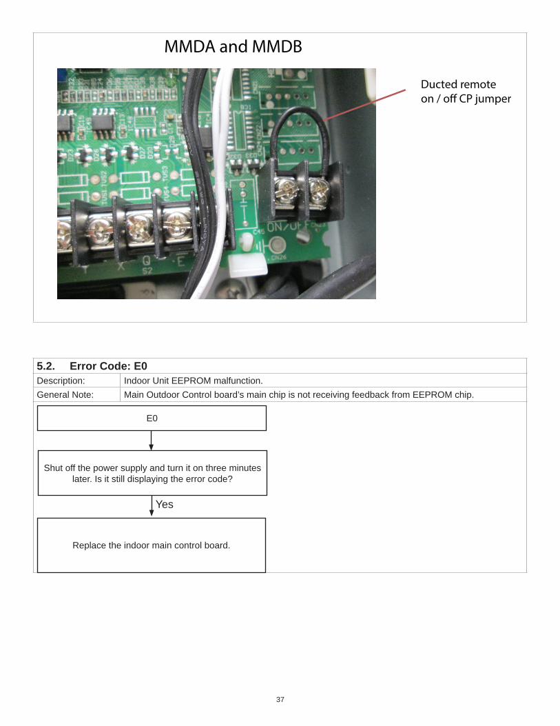
37
Ducted remoteon / o� CP jumper
MMDA and MMDB
5.2. Error Code: E0Description: Indoor Unit EEPROM malfunction. General Note: Main Outdoor Control board’s main chip is not receiving feedback from EEPROM chip.
E0
Shut off the power supply and turn it on three minutes later. Is it still displaying the error code?
Yes
Replace the indoor main control board.

38
5.3. Error Code: E1Malfunction decision conditions:
Indoor unit did not receive feedback from outdoor unit for 110 seconds and this condition has repeated four times continuously.
Supposed causes • Wiring error• Indoor or outdoor main control board fault
Yes
No
.Replace the outdoor main control.
Power on. Is the errorextinguished?
Check the outdoor wiring connection.Is the wiring correctly?
Replace the indoor main control.Power on. Is the error
extinguished?
Yes
Replace the outdoor main control.
No
Replace the indoor main control..
No
Ohm outdoor components, EEV, outdoor fan, compressor andcheck refrigerant charge.
heck the indoor wiring connectionIs the wiring correctly?
Yes
Yes
Check whether reactoris normal?
Yes
Replace the reactor No
C
Yes
Power off system. Wait two minutes and powersystem back on. Is error code still present?
Measure Vs. Is the voltage alternating between positive and negative numbers?

39
Error Code: E1 (continued)
REMARK: Use a multimeter to test the DC voltagebetween L2 and L3 of outdoor unit. The red pin ofthe multimeter connects with L2 while the black pin is for L3.
When AC is running normally, the votlage willmove alternately between a negative and a positive number.
If positive reading the outdoor board needs to be replaced.
REMARK: Use a multimeter to test theresistance of the reactor which does notconnect with the capacitor.The normal value should be around zeroohm. Otherwise, the reactor has malfunctioned.
If negative reading then the indoor board needs to be replaced.
40
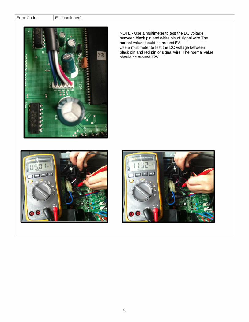
Error Code: E1 (continued)
NOTE - Use a multimeter to test the DC voltage between black pin and white pin of signal wire The normal value should be around 5V.Use a multimeter to test the DC voltage between black pin and red pin of signal wire. The normal value should be around 12V.

41
5.4. Error Code: E3Description: Indoor fan speed error.General Note: When indoor fan speed runs too low (300 RPM) for a predefined amount of time, the unit will stop
and the LED will display the error.
Indoor fan speed error
Power off indoor unit. Wait two minutes and then restart. Is error codes still be-
ing displayed?
No
Shut off power supply and rotate fan by hand. Does fan spin freely?
Yes
The unit operates normally.
Check the wiring of the fan motor. Is it connected correctly?
Yes
Measure the voltage for the fan motor from the main indoor control. Is the volt-
age correct?
No
Yes
No Remove obstruction.
NoCorrect the
connections.
Replace the main indoor control. Did this resolve the issue?
No
Replace the fan motor
Indoor DC Fan Motor Check1. Indoor DC fan motor (Control Chip is in Fan
Motor)2. Turn power on and while the unit is on standby,
measure the voltage between pin 1 and pin 3 as well as between pin 4 and pin 3 in fan motor connector. If the value of the voltage is not within the range shown in the following table, the indoor unit main control board may be experiencing problems and need to be replaced.
DC Motor Voltage Input and OutputNO. Color Signal Voltage
1 Red Vs/Vm 200~380V
2 --- --- ---
3 Black GND 0V
4 White Vcc 13.5~16.5V
5 Yellow Vsp 0~6.5V
6 Blue FG 13.5~16.5V

42
5.5. Error Code: E4Description: Indoor return air temperature (T1) sensor error.General Note: If the voltage is lower than 0.06V or higher than 4.94V, the LED will display this error.
Temperature sensor error
Check the connections between tempera-ture sensor and indoor unit main control
board. Are the connections good?
Yes
No
No Correct the connections
Check the resistance value of the sensor using “Table 11. Temperature Sensor
Resistance Value Table (°F/°C)” on page 63.
Yes Replace indoor unit main control board.Is it normal?
No
Replace the sensor.

43
5.6. Error Code: E5Description: Indoor Coil Temperature (T2) Sensor ErrorGeneral Note: If the voltage is lower than 0.06V or higher than 4.94V, the LED will display the error.
Check the connections between tempera-ture sensor and indoor unit main control
board. Are the connections good?
Yes
No Correct the connections
Check the resistance value of the sensor using “Table 11. Temperature Sensor
Resistance Value Table (°F/°C)” on page 63.
YesReplace either the
indoor or outdoor main control board..
Is it normal? Have you checked the tem-perature at that location?
No
Replace the sensor.

44
5.7. Error Code: ECDescription: Low Refrigerant ErrorGeneral Note: The system monitors the value of evaporator coil sensor T2 for the first 5 minutes after startup.
If the temperature of T2 drops per this formula three times in the first 5 minutes of operation, the system shuts down and the error code is displayed.For this formula “Tcool” = the T2 temperature at startup. T2 < Tcool - 3.6°F (2°C)
EC
Power off system. Wait two minutes and restart system. Is error code still pres-
ent?
No
Yes Check the T2 sensor. Is it functioningCheck to see if cool air is blowing out of
the indoor air outlet
NoYes
Replace the indoor main control board.
Check for refrigerant leaks.
NoYes Repair leaks and re-
charge system.
Check for restriction in refrigerant lines and clear restrictions if present.
Problem resolved.
Yes

45
5.8. Error Code: EEDescription: Condensate switch (water level) alarm malfunction. (For M22A, M33A/B and MMDA units)General Note: If the sampling voltage is not 5V, the LED will display this failure.
• Wiring mistakes• Faulty water-level switch• Faulty water pump• Faulty indoor main control board.
NOTE: Float is in the down postilion unless the condensate is restricted and the float has risen.
NOTE: Water pump runs 100% of the time when the unit is calling for cooling.
Power off system then wait three minutes and restart. Is error codestill present?
Is the condensate switch installed
correctly?
Yes
Reposition the condensate switch.No
Is the condensate switch broken?
Yes
Replace the condensate switch. Yes
Replace the water pump. If malfunction is
still not resolved, then replace the indoor
main control board.
No

46
5.9. Error Code: F0Description: Outdoor compressor current overload sensedGeneral Note: If the outdoor current exceeds the current limit value, the LED will display this failure.
Check whether the input current of the power supply should not exceed more than:
18K - 12A. 30K - 18.5A. 36K - 23A
Yes
Check whether the refrigerant system is OK.
Check whether the outdoor ambient temperatureis higher than 50°C or 122 F
No
Replace outdoor main board.No
Stop the unit.Yes
Check if outdoor unit has proper ventilation.
Yes
Correct poor ventilation to outdoor unit.No
Check outdoor coils. Outdoor coils should be clean and free of any debris. Clean outdoor coils.
No
Yes
Is the refrigerant piping restricted?Recover refrigerant and remove restriction(s).
Perform proper vacuum procedures, then restart system.
Yes
No
Replace outdoor main board, and check whether the system can run normally.
No
Replace the electric control box. Problem Solved.Yes
Yes

47
5.10. Error Code: F1Description: Outdoor Temperature Sensor T4 Error.General Note: If the voltage is lower than 0.06V or higher than 4.94V, the LED will display the error.
Check the connections between tempera-ture sensor and main outdoor control. Are
the connections good?
Yes
No Correct the connections
Check the resistance value of the sensor using “Table 11. Temperature Sensor
Resistance Value Table (°F/°C)” on page 63.
YesReplace either the
indoor or outdoor main control board.
Is it normal?
No
Replace the sensor.

48
5.11. Error Code: F2Description: Faulty Outdoor Coil Temperature Sensor T3General Note: If the voltage is lower than 0.06V or higher than 4.94V, the LED will display the error.
Check the connections between tem-perature sensor and outdoor main control
board. Are the connections good?
Yes
No Correct the connections
Check the resistance value of the sensor using “Table 11. Temperature Sensor
Resistance Value Table (°F/°C)” on page 63.
YesReplace either the
indoor or outdoor main control board.
Is it normal?
No
Replace the sensor.

49
5.12. Error Code: F3Description: Compressor discharge temperature sensor errorGeneral Note: When the compressor discharge temperature (T5) is more than 239°F (115°C) for 10 seconds, the
compressor will stop and restart once T5 is less than 194°F (90°C).
Temperature protection of compressor.
Check whether the compressor discharge tempera-ture is more than 239°F (115°C) ?
No
Check whether the connection is right between com-pressor discharge temperature sensor and outdoor
unit main control according to wiring diagrams?
Check for refrigerant leaks.
Yes Locate and repair the leak and weight in the charge
Yes
Correct the wiring.No
Yes
Measure the resistance value of compressor dis-charge temperature sensor. Refer to “Table 12.
Discharge Temperature Sensor Table (°C--K)” on page 64.
Replace the compressor discharge temperature
sensor.
No
Yes
Replace outdoor main control board.
No
Replace high pressure valve assembly.
Did that correct the leak?
No

50
5.13. Error Code: F4Description: Outdoor EEPROM error. General Note: Main outdoor control board main chip is not receiving feedback from EEPROM chip. For the
location of EEPROM chip, please refer to the below image.
Outdoor EEPROM malfunction
Power off the outdoor unit. Then wait three minutes and restart unit.
Does the problem still exist?
Outdoor PCB(M3OC-30HRFN1-M)
Yes
Replace the outdoor main control board.

51
5.14. Error Code: F5Description: Outdoor unit fan speed errorGeneral Note: When outdoor fan speed is to slow (300 RPM) or too fast (2400 RPM) for a predefined amount of
time. The unit will stop and the LED will display the failure.
Outdoor fan speed malfunction
Power off outdoor unit. Then wait three minutes and restart unit. Is it still display-
ing the error code?
Yes
Shut off the power supply and inspect all components for damage. Rotate the fanby hand. The fan should offer little resis-tance when manually spun. Wheel and shaft should spin evenly and balanced.
Yes
Check all wiring connections.
Yes
Check outdoor fan. (See “4.7. Error Code: E8” on page 23.
Did the unit operates normally?No
Yes
Replace the fan motor.
Make necessary corrections No
Correct faulty corrections.No
Replace the main outdoor control board.No
No

52
5.15. Error Code: F6Description: Indoor Unit Evaporator Outlet Coil Temperature (T2) Sensor FaultyGeneral Note: If the voltage is lower than 0.06V or higher than 4.94V, the LED will display the error.
Temperature sensor error
Check the connections between tempera-ture sensor and indoor unit main control.
Are the connections good?
Yes
No
No Correct the connections
Check the resistance value of the sensor using “Table 11. Temperature Sensor
Resistance Value Table (°F/°C)” on page 63.
YesReplace either the
indoor or outdoor main control.
Is it normal?
No
Replace the sensor.

53
5.16. Error Code: P0Description: Integrate Power Module (IPM) module or Insulated gate bipolar transistor (IGBT) over current
protection.General Note: When the voltage signal that IPM sends to the compressor drive chip is abnormal, the display LED
will show “P6” and unit will turn Off.
P6
Check whether the voltage range of P-N on IPM module is normal?
18 - 30K = 277-356VDC 36K - 277 = 410VDC -
Check whether the connecting wiring between main board and the IPM module is connected
tightly.
YesYes
NoCheck whether the
input power supply is correct? 208-230V,
1PH, 60HzNo
No
Correct the incom-ing power problem, then check whether the system operates
normally
Check whether the power supply line is connected
correctly and tight
Yes
Check all connections on the outdoor unit
main board.
Yes
Check whether the bridge rectifiers are normal? Use the multimeter to measure the resistance between each two terminals, check whether there is the condition that value of resistance
is 0.
Replace the bridge rectifiers.
No
Yes
Check whether the wiring of each reactor is correct?
Replace the wiring or reactor or replace the PFC module
No
No Connection was tighten, did that correct
the issue?
NoYes
Replace the IPM module, check whether the system
works normally.
No
Check if the outdoor fan runs properly or the outdoor coil
is clean.
For AC fan models, check whether the resistance of the fan motor
is normal. If not, replace the fan motor. For DC fan models,
refer to the solution of fan speed malfunction (E8) . Find out the
cause and repair it.
Yes
No
Replace the outdoor unit main board; check whether the system
operates normally?
No
Yes
Replace the compressor, check whether the system operates
normally?
Problem Solved
Yes
Yes
Check whether the connecting wiring to the compressor is connected correctly and tightly
Connection was tighten, did that correct
the issue?
NoYes
Yes
Problem Solved

54
Error Code: P0 (continued)
P-U
P-V
P-W
P-N
55
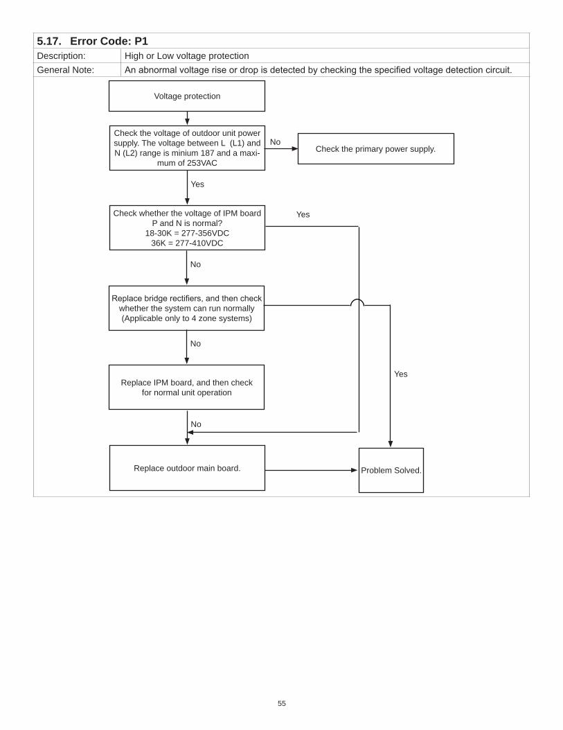
5.17. Error Code: P1Description: High or Low voltage protection General Note: An abnormal voltage rise or drop is detected by checking the specified voltage detection circuit.
Voltage protection
Check the voltage of outdoor unit power supply. The voltage between L (L1) and N (L2) range is minium 187 and a maxi-
mum of 253VAC
Yes
Check whether the voltage of IPM board P and N is normal?
18-30K = 277-356VDC 36K = 277-410VDC
No
Replace bridge rectifiers, and then check whether the system can run normally (Applicable only to 4 zone systems)
No
Replace IPM board, and then checkfor normal unit operation
No
Replace outdoor main board. Problem Solved.
Yes
Yes
Check the primary power supply.No

56
5.18. Error Code: P2Description: Compressor top high temperature protection (OLP)General Note: If the sampling voltage is not 5V, the LED will display the P2 error code.
P2
Check the air flow of indoor and outdoor units. Does a problem exist?
No
Clear air flow blockage.Yes
Power off the unit and wait 10 minutes before restarting.
Check compressor temperature. Is it within acceptable parameters?
Check the overload protector. Is it properly wired?
No No
Yes
Measure the resistance between the two ports of the OLP. Is it zero?
Yes
Replace the outdoor control board.
NoReplace the OLP.
Ensure a proper connection.
Yes

57
5.19. Error Code: P3Description: Outdoor unit low temperature lockout.General Note: The outdoor unit will lockout in heating mode when the outdoor temperature is lower than -13°F
(-25°C) for one hour, on MPA and MPB units. For MLA unit the lockout occurs at -22 F. The outdoor unit will resume operation when either:• Outdoor temperature is higher than -7.6°F (-22°C) for 10 minutes and compressor has been
stopped for one hour • Outdoor temperature is higher than 23°F (-5°C) for 10 minutes
5.20. Error Code: P4Description: Compressor Drive ErrorGeneral Note: An abnormal inverter compressor drive is detected by a special detection circuit, including
communication signal detection, voltage detection, compressor rotation speed signal detection and etc
Compressor Drive Error
Is the wiring connections between the compressor and the main control board good?
Yes
Make necessary corrections.No
Is the IPM (integrated power module) okay? (See “Table 15. Normal Resistance Values” on page 66
for troubleshooting.
Replace either the IPM or main outdoor control board..
No
Yes
Check the outdoor fan and does the unit have correct clearances and outdoor coil clear.
Refer to the error code fan speed mal-function (E8). See “4.7. Error Code: E8”
on page 23.
No
Yes
Are the compressor resistance windings within speci-fication? Replace the compressor.
No
Yes
Replace the outdoor main control board.
58
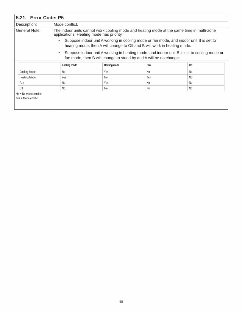
5.21. Error Code: P5Description: Mode conflict.General Note: The indoor units cannot work cooling mode and heating mode at the same time in multi-zone
applications. Heating mode has priority.• Suppose indoor unit A working in cooling mode or fan mode, and indoor unit B is set to
heating mode, then A will change to Off and B will work in heating mode.
• Suppose indoor unit A working in heating mode, and indoor unit B is set to cooling mode or fan mode, then B will change to stand by and A will be no change.
Cooling mode Heating mode Fan Off
Cooling Mode No Yes No NoHeating Mode Yes No Yes NoFan No Yes No NoOff No No No No
No = No mode conflict.Yes = Mode conflict

59
5.22. Error Code: P6Description: Compressor high-pressure or low-pressure switch openGeneral Note: If the sampling voltage of pressure switch is not 5V, the LED will display the failure.
Test each pressure switch separately following the two provided flow charts.
Check wiring connections between high pressure switch and main outdoor control board.
Yes
Determine if High pressure switch is faulty.
Method: Disconnect the plug. Measure the resistance of the high pressure protector, if the protector is normal
the value is 0.
Yes
Make necessary corrections.No
Replace high pressure protection switch.No
Check the outdoor ambient temperature. The outdoor ambient temperature should not be higher than 50 °C
or 122 °F.
No
Stop the unit.Yes
Check if the outdoor unit clearance is good?
Yes
Make corrections to allow for proper ventilation
No
Check if the outdoor fan runs properlySee Fault code E8 to properly diagnose outdoor fan motor. See “4.7. Error Code:
E8” on page 23.
No
Yes
Check outdoor coils. The outdoor unit coils should be clean and free of any debris.
Clean outdoor coils.No
Yes
Check whether the refrigerant system is OK.
Yes
Replace outdoor main board.

60
Error Code: P6 (continued)
Low Pressure Connection
Is the wiring between the low pressure switch and main control board is connected properly.
Yes
Disconnect the plug. Measure the resistance of the low pressure switch, if the switch is normal the value is 0.
Yes
Connect it properly..No
Replace low pressure protector.No
Is the outdoor temperature with in the unit operation limits?
No
Stop the unit.Yes
Check whether the high pressure valve master or zone is opened.
Yes
Fully open the high pressure valve.No
Check if the indoor fan runs properly in cooling mode.Refer to the solution of fan speed mal-
function (E8). Find out the cause correct it (see “4.7. Error Code: E8” on page 23.
No
Yes
Replace outdoor main board.
No
Is the system refrigerant correct? Is it too low? Check for leaks and add refrigerant

61
Error Code: P6 (continued)

62
6. Over-Voltage or Under-Voltage Protection Diagnosis and Solution
Voltage protection
Check the voltage of outdoor unit power supply. The voltage between
L (L1) and N (L2) should have a minium range of 187 and maximum of 253VAC.
Yes
Check whether the voltage of IPM board P and N is normal?
18-30K = 277-356VDC36K = 277-410VDC
No
Replace bridge rectifiers, and then check whether the system can run normally(This is only applicable to 4 zone sys-
tems.)
No
Replace IPM board, and then checkfor normal unit operation
No
Replace outdoor main board. Problem Solved.
Yes
Yes
Check the primary power supply.No

63
7. Temperature Sensor Resistance ValuesTable 11. Temperature Sensor Resistance Value Table (°F/°C)
°F °C K Ohm °F °C K Ohm °F °C K Ohm °F °C K Ohm
-4 -20 115.266 68 20 12.6431 140 60 2.35774 212 100 0.62973
-2.2 -19 108.146 69.8 21 12.0561 141.8 61 2.27249 213.8 101 0.61148
-0.4 -18 101.517 71.6 22 11.5 143.6 62 2.19073 215.6 102 0.59386
1.4 -17 96.3423 73.4 23 10.9731 145.4 63 2.11241 217.4 103 0.57683
3.2 -16 89.5865 75.2 24 10.4736 147.2 64 2.03732 219.2 104 0.56038
5 -15 84.219 77 25 10 149 65 1.96532 221 105 0.54448
6.8 -14 79.311 78.8 26 9.55074 150.8 66 1.89627 222.8 106 0.52912
8.6 -13 74.536 80.6 27 9.12445 152.6 67 1.83003 224.6 107 0.51426
10.4 -12 70.1698 82.4 28 8.71983 154.4 68 1.76647 226.4 108 0.49989
12.2 -11 66.0898 84.2 29 8.33566 156.2 69 1.70547 228.2 109 0.486
14 -10 62.2756 86 30 7.97078 158 70 1.64691 230 110 0.47256
15.8 -9 58.7079 87.8 31 7.62411 159.8 71 1.59068 231.8 111 0.45957
17.6 -8 56.3694 89.6 32 7.29464 161.6 72 1.53668 233.6 112 0.44699
19.4 -7 52.2438 91.4 33 6.98142 163.4 73 1.48481 235.4 113 0.43482
21.2 -6 49.3161 93.2 34 6.68355 165.2 74 1.43498 237.2 114 0.42304
23 -5 46.5725 95 35 6.40021 167 75 1.38703 239 115 0.41164
24.8 -4 44 96.8 36 6.13059 168.8 76 1.34105 240.8 116 0.4006
26.6 -3 41.5878 98.6 37 5.87359 170.6 77 1.29078 242.6 117 0.38991
28.4 -2 39.8239 100.4 38 5.62961 172.4 78 1.25423 244.4 118 0.37956
30.2 -1 37.1988 102.2 39 5.39689 174.2 79 1.2133 246.2 119 0.36954
32 0 35.2024 104 40 5.17519 176 80 1.17393 248 120 0.35982
33.8 1 33.3269 105.8 41 4.96392 177.8 81 1.13604 249.8 121 0.35042
35.6 2 31.5635 107.6 42 4.76253 179.6 82 1.09958 251.6 122 0.3413
37.4 3 29.9058 109.4 43 4.5705 181.4 83 1.06448 253.4 123 0.33246
39.2 4 28.3459 111.2 44 4.38736 183.2 84 1.03069 255.2 124 0.3239
41 5 26.8778 113 45 4.21263 185 85 0.99815 257 125 0.31559
42.8 6 25.4954 114.8 46 4.04589 186.8 86 0.96681 258.8 126 0.30754
44.6 7 24.1932 116.6 47 3.88673 188.6 87 0.93662 260.6 127 0.29974
46.4 8 22.5662 118.4 48 3.73476 190.4 88 0.90753 262.4 128 0.29216
48.2 9 21.8094 120.2 49 3.58962 192.2 89 0.8795 264.2 129 0.28482
50 10 20.7184 122 50 3.45097 194 90 0.85248 266 130 0.2777
51.8 11 19.6891 123.8 51 3.31847 195.8 91 0.82643 267.8 131 0.27078
53.6 12 18.7177 125.6 52 3.19183 197.6 92 0.80132 269.6 132 0.26408
55.4 13 17.8005 127.4 53 3.07075 199.4 93 0.77709 271.4 133 0.25757
57.2 14 16.9341 129.2 54 2.95896 201.2 94 0.75373 273.2 134 0.25125
59 15 16.1156 131 55 2.84421 203 95 0.73119 275 135 0.24512
60.8 16 15.3418 132.8 56 2.73823 204.8 96 0.70944 276.8 136 0.23916
62.6 17 14.6181 134.6 57 2.63682 206.6 97 0.68844 278.6 137 0.23338
64.4 18 13.918 136.4 58 2.53973 208.4 98 0.66818 280.4 138 0.22776
66.2 19 13.2631 138.2 59 2.44677 210.2 99 0.64862 282.2 139 0.22231

64
8. Discharge Temperature Sensor Resistance ValuesTable 12. Discharge Temperature Sensor Table (°C--K)
°F °C K Ohm °F °C K Ohm °F °C K Ohm °F °C K Ohm
-4 -20 542.7 68 20 68.66 140 60 13.59 212 100 3.702
-2.2 -19 511.9 69.8 21 65.62 141.8 61 13.11 213.8 101 3.595
-0.4 -18 455.9 71.6 22 59.98 143.6 62 12.21 215.6 102 3.392
1.4 -17 455.9 73.4 23 59.98 145.4 63 12.21 217.4 103 3.392
3.2 -16 430.5 75.2 24 57.37 147.2 64 11.79 219.2 104 3.296
5 -15 406.7 77 25 54.89 149 65 11.38 221 105 3.203
6.8 -14 384.3 78.8 26 52.53 150.8 66 10.99 222.8 106 3.113
8.6 -13 363.3 80.6 27 50.28 152.6 67 10.61 224.6 107 3.025
10.4 -12 343.6 82.4 28 48.14 154.4 68 10.25 226.4 108 2.941
12.2 -11 325.1 84.2 29 46.11 156.2 69 9.902 228.2 109 2.86
14 -10 307.7 86 30 44.17 158 70 9.569 230 110 2.781
15.8 -9 291.3 87.8 31 42.33 159.8 71 9.248 231.8 111 2.704
17.6 -8 275.9 89.6 32 40.57 161.6 72 8.94 233.6 112 2.63
19.4 -7 261.4 91.4 33 38.89 163.4 73 8.643 235.4 113 2.559
21.2 -6 247.8 93.2 34 37.3 165.2 74 8.358 237.2 114 2.489
23 -5 234.9 95 35 35.78 167 75 8.084 239 115 2.422
24.8 -4 222.8 96.8 36 34.32 168.8 76 7.82 240.8 116 2.357
26.6 -3 211.4 98.6 37 32.94 170.6 77 7.566 242.6 117 2.294
28.4 -2 200.7 100.4 38 31.62 172.4 78 7.321 244.4 118 2.233
30.2 -1 190.5 102.2 39 30.36 174.2 79 7.086 246.2 119 2.174
32 0 180.9 104 40 29.15 176 80 6.859 248 120 2.117
33.8 1 171.9 105.8 41 28 177.8 81 6.641 249.8 121 2.061
35.6 2 163.3 107.6 42 26.9 179.6 82 6.43 251.6 122 2.007
37.4 3 155.2 109.4 43 25.86 181.4 83 6.228 253.4 123 1.955
39.2 4 147.6 111.2 44 24.85 183.2 84 6.033 255.2 124 1.905
41 5 140.4 113 45 23.89 185 85 5.844 257 125 1.856
42.8 6 133.5 114.8 46 22.89 186.8 86 5.663 258.8 126 1.808
44.6 7 127.1 116.6 47 22.1 188.6 87 5.488 260.6 127 1.762
46.4 8 121 118.4 48 21.26 190.4 88 5.32 262.4 128 1.717
48.2 9 115.2 120.2 49 20.46 192.2 89 5.157 264.2 129 1.674
50 10 109.8 122 50 19.69 194 90 5 266 130 1.632
51.8 11 104.6 123.8 51 18.96 195.8 91 4.849
53.6 12 99.69 125.6 52 18.26 197.6 92 4.703
55.4 13 95.05 127.4 53 17.58 199.4 93 4.562
57.2 14 90.66 129.2 54 16.94 201.2 94 4.426
59 15 86.49 131 55 16.32 203 95 4.294 B(25/50)=3950K
60.8 16 82.54 132.8 56 15.73 204.8 96 4.167
62.6 17 78.79 134.6 57 15.16 206.6 97 4.045 R(90°C)=5KΩ±3%
64.4 18 75.24 136.4 58 14.62 208.4 98 3.927
66.2 19 71.86 138.2 59 210.2 99 3.812

65
9. TemperatureSensorIdentificationTableTable 13. TemperatureSensorIdentificationTable
Sensor Number Sensor Name
T1 ID Return Air
T2 Indoor Coil
T2B Coil temperature of indoor heat exchanger outlet. (Located in outdoor unit)
T3 Outdoor Coil
T4 OD ambient temp
T5 Compressor Discharge
10. Component Diagnostics
10.1. Compressor CheckMeasure the resistance value of each winding by using the tester. This can also be used to check for shorted compressor windings, and identifying terminals when they are no longer legible.
Figure 4. Compressor Terminals
Table 14. Model / Compressor Cross-ReferenceODU Model # Compressor Model # Blue - Red Blue - Black Red - Blue
MPA012S4S-1L MPA012S4S-1P ASM108D1UFZA 1.81Ω (20°C /68°F)
MPB009S4S-1L MPB012S4S-1L ASM98D32UFZ 2.25 Ω (20°C /68°F)
MPB009S4S-1P ASN98D22UFZ 1.57 Ω (20°C /68°F)MPB012S4S-1P ASN98D22UFZ 2.25 Ω (20°C /68°F)MPA009S4S-1L MPA009S4S-1P ASM98D1UFZA 1.81Ω (20°C /68°F)
MPA018S4S-1P ASM135D23UFZ 1.75Ω (20°C /68°F)MPB018S4S-1P ASM135D23UFZ 1.65 Ω (20°C /68°F)MPA024S4S-1P DA250S2C-30MT 0.55Ω (20°C /68°F)MPB024S4S-1P ATF235D22UMT 0.75 Ω (20°C /68°F)MPA030S4S-1P TNB306FPGMC-L 0.53Ω (20°C /68°F)MPB030S4S-1P ATF250D22UMT 0.65 Ω (20°C /68°F)MPA036S4S-1P TNB306FPGMC-L 0.53Ω (20°C /68°F)MPB036S4S-1P ATF310D43UMT 0.65 Ω (20°C /68°F)MPA048S4S-1P MNB36FAAMC-L 0.44Ω (20°C /68°F)MPB048S4S-1P ATQ420D1UMU 0.378 Ω (20°C /68°F)MPA018S4M-1P DA150S1C-20FZ 0.95Ω (20°C /68°F)MPB018S4M-1P ATM150D23UFZ 1.72 Ω (20°C /68°F)MPA030S4M-1P DA250S2C-30MT 0.55Ω (20°C /68°F)MPB030S4M-1P ATF235D22UMT 0.75 Ω (20°C /68°F)MPA036S4M-1P TNB306FPGMC-L 0.53Ω (20°C /68°F)MPB036S4M-1P ATF310D43UMT 0.65 Ω (20°C /68°F)MPA048S4M-1P MNB36FAAMC-L 0.44Ω (20°C /68°F)MPB048S4M-1P ATQ360D1UMU 0.37 Ω (20°C /68°F)MLA009S4S-1PMLA012S4S-1P
ATM115D43UFZ2 1.87 Ω
MLA018S4S-1PMLA024S4S-1P
ATF235D22UMT 0.75 Ω

66
Table 14. Model / Compressor Cross-ReferenceODU Model # Compressor Model # Blue - Red Blue - Black Red - Blue
MLA018S4M-1P ATF235D22UMT 0.75 Ω
MLA030S4M-1P ATF310D43UMT 0.65 Ω
MLA036S4M-1P ATQ360D1UMU 0.37 Ω
10.2. IPM CheckMeasure the resistance value of each winding by using the tester.Turn off the power, let the large capacity electrolytic capacitors discharge completely, and unplug the IPM. Use a digital tester to measure the resistance between P and UVWN; UVW and N.
Table 15. Normal Resistance ValuesDigital Tester Normal Resistance Value Digital Tester Normal Resistance Value
(+)Red (-)Black
∞(Several MΩ)
(+)Red (-)Black
∞(Several MΩ)P
N U
NU V
V W
W (+)Red
NOTE: Any Meg ohm reading is good
Figure 5. Testing

67
10.3. Fan Motors
10.3.1. AC Fan MotorPower on and set the unit running in fan mode at high fan speed. After running for 15 seconds, measure the voltage of pin 1 and pin 2. If the value of the voltage is less than 100V (208~240V power supply) or 50V(115V power supply), the main control board may have issues and will need to be replaced.
Figure 6. Terminals
Table 16. Resistance Value for AC or DC Fan Motors
PositionResistance Value
RPG20B RPG28H
Black - Red 381Ω±8% (20°C)(Brand: Weiling)
342Ω±8% (20°C)(Brand: Dayang)
183.6Ω±8% (20°C)(Brand: Weiling)
180Ω±8% (20°C)(Brand: Wolong)
White - Black 267Ω±8% (20°C)(Brand: Weiling)
253Ω±8% (20°C)(Brand: Dayang)
206Ω±8% (20°C)(Brand: Weiling)
190Ω±8% (20°C)(Brand: Wolong)
Measure the resistance value of each winding by using the tester
Figure 7. Terminals

68
Table 17. Resistance Values for DC Fan Motors
PositionResistance Value
YDK70-6FB YDK180-8GB YSK27-4G YSK68-4B YDK45-6B YSK25-6L YDK53-6FB(B)
Black - Red 56Ω±8% (20°C) 24.5Ω±8% (20°C) 317Ω±8% (20°C) 145Ω±8% (20°C) 345Ω±8% (20°C) 627Ω±8% (20°C) 88.5Ω±8% (20°C)
Red - Yellow 76Ω±8% (20°C) 19Ω±8% (20°C) 252Ω±8% (20°C) 88Ω±8% (20°C) 150Ω±8% (20°C) 374.3Ω±8% (20°C) 138Ω±8% (20°C)
Yellow - Blue 76Ω±8% (20°C) 19Ω±8% (20°C) 252Ω±8% (20°C) 88Ω±8% (20°C) 150Ω±8% (20°C) 374.3Ω±8% (20°C) 138Ω±8% (20°C)
Table 18. Resistance Value for DC Fan Motors
Unit Product Capacity Voltage LENNOX model Catalog Number Part Number Motor Model Resistance (Ω)
IDU Ducted 9K 208-230V MMDA009S4-1P 14A23 22023011000630 ZKFN-55-8-1 46.5
IDU Ducted 12K 208-230V MMDA012S4-1P 14A24 22023011000631 ZKFN-55-8-1 46.5
IDU Ducted 18K 208-230V MMDA018S4-1P 14A25 22023011000632 ZKFN-90-8-1 43
IDU Ducted 24K 208-230V MMDA024S4-1P 14A26 22023011000633 ZKFN-90-8-1 43
IDU Ducted 9K 208-230V MMDA009S4-2P 15V30 22023011000630 ZKFN-55-8-1 46.5
IDU Ducted 12K 208-230V MMDA012S4-2P 15V31 22023011000631 ZKFN-55-8-1 46.5
IDU Ducted 18K 208-230V MMDA018S4-2P 15V32 22023011000632 ZKFN-90-8-1 43
IDU Ducted 24K 208-230V MMDA024S4-2P 15V33 22023011000633 ZKFN-90-8-1 43
IDU Ducted 36K 208-230V MMDA036S4-1P 14A27 22023011000519 ZKFN-150-8-1 30
IDU Ducted 48K 208-230V MMDA048S4-1P 14A28 22023011000450 ZKFN-240-8-1 10.2
IDU Ducted 9K 208-230V MMD 16H58 22023011003874 ZKFN-55-8-22 46.5
IDU Ducted 12K 208-230V MMD 16H59 22023011003875 ZKFN-55-8-22 46.5
IDU Ducted 18K 208-230V MMD 16H60 22023011003474 ZKFN-160-8-1-2 17.8
IDU Ducted 24K 208-230V MMD 16H61 22023011003414 ZKFN-160-8-1-2 17.8
IDU Ducted 36K 208-230V MMD 16H62 22023011003415 ZKFN-300-8-1 6.74
IDU Ducted 48K 208-230V MMD 16H63 22023011003416 ZKFN-560-8-1-1 4
IDU Ceiling-flooring 18K 208-230V MCFB018S4-2P 15U56 22022711000996 ZKFN-55-8-1 46.5
IDU Ceiling-flooring 24K 208-230V MCFA024S4-1P 14A31 22022711000421 ZKFN-55-8-1 46.5
IDU Ceiling-flooring 24K 208-230V MCFA024S4-2P 15V34 22022711000421 ZKFN-55-8-1 46.5
IDU Ceiling-flooring 36K 208-230V MCFA036S4-1P 14A32 22022711000659 ZKFN-115-8-1 42
IDU Ceiling-flooring 48K 208-230V MCFA048S4-1P 14A33 22022711000658 ZKFN-90-8-1 43
IDU Casstte 48K 208-230V M33B048S4-1P 15U55 22022511001716 ZKFN-170-8-1 22
ODU Standard SZ 9K 115V MPB009S4S-1L 15U57 22022016006440 ZKFN-40-8-1L 100
ODU Standard SZ 12K 115V MPB012S4S-1L 15U41 22022016006439 ZKFN-40-8-1L 100
ODU Standard SZ 9K 208-230V MPB009S4S-1P 15U42 22022016005160 ZKFN-40-8-1L 100
ODU Standard SZ 12K 208-230V MPB012S4S-1P 15U43 22022016005161 ZKFN-40-8-1L 100
ODU Standard SZ 18K 208-230V MPB018S4S-1P 15U44 22022016005162 ZKFN-50-8-2 37.3
ODU Standard SZ 24K 208-230V MPB024S4S-1P 15U45 22022016005121 ZKFN-120-8-2 42
ODU Standard SZ 30K 208-230V MPB030S4S-1P 15U46 22022016005119 ZKFN-120-8-2 42

69
Table 18. Resistance Value for DC Fan Motors
Unit Product Capacity Voltage LENNOX model Catalog Number Part Number Motor Model Resistance (Ω)
ODU Standard SZ 36K 208-230V MP 16H57 22022016005120 ZKFN-120-8-2 42
ODU Standard SZ 36K 208-230V MP 15U47 22022516000402 ZKFN-120-8-2 42
ODU Standard SZ 48K 208-230V MP 15U50 22022516000702 ZKFN-85-8-22-2 32.3
ODU Cold climate SZ 9K 208-230V MLA009S4S-1P 14X75 22022016004895 ZKFN-40-8-1L 100
ODU Cold climate SZ 12K 208-230V MLA012S4S-1P 14X76 22022016004875 ZKFN-40-8-1L 100
ODU Cold climate SZ 18K 208-230V MLA018S4S-1P 14X77 22022016005062 ZKFN-50-8-2 37.3
ODU Cold climate SZ 24K 208-230V MLA024S4S-1P 14X78 32022016000001 ZKFN-120-8-2 42
ODU Standard multi zone 18K 208-230V MP 15U48 22022316000385 ZKFN-50-8-2 37.3
ODU Standard multi zone 30K 208-230V MP 15U49 22022316000327 ZKFN-120-8-2 42
ODU Standard multi zone 36K 208-230V MP 15U40 22022316000326 ZKFN-120-8-2 42
ODU Standard multi zone 48K 208-230V MP 15U51 22022316000545 ZKFN-85-8-22-2 32.3
ODU Cold climate MZ 18K 208-230V MLA018S4M-1P 14X79 22022316000327 ZKFN-120-8-2 42
ODU Cold climate MZ 30K 208-230V MLA030S4M-1P 14X80 22022316000326 ZKFN-120-8-2 42
ODU Cold climate MZ 36K 208-230V MLA036S4M-1P 14X81 22022316000545 ZKFN-85-8-22-2 32.3
IDU Ceiling-flooring 18K 208-230V MCFA018S4-1P 14A30 22022711000432 ZKFN-55-8-1 46.5
ODU Current SZ 9K 208-230V MPA009S4S-1P 14A05 22022016001776 ZKFN-40-8-5 52.5
ODU Current SZ 12K 208-230V MPA012S4S-1P 14A06 22022016003852 ZKFN-40-8-5 52.5
ODU Current SZ 18K 208-230V MPA018S4S-1P 14A07 22022016002776 ZKFN-50-8-2 37.3
ODU Current SZ 30K 208-230V MPA030S4S-1P 14A09 22022016002857 ZKFN-120-8-2 42
ODU Current SZ 36K 208-230V MPA036S4S 14A10 22023016000215 ZKFN-120-8-2 42
ODU Current MZ 36K 208-230V MPA036S4M 14A36 22022316000128 ZKFN-120-8-2 42

70
10.3.2. DC Fan Motor (Control Chip is Inside Fan Motor)Power on and when the unit is in standby, measure the voltage of pin 1 to pin 3, pin 4 to pin 3 in fan motor connector. If the value of the voltage is not in the range showing in below table, the printed circuit board must have problems and needs to be replaced.For other models:
Figure 8. PinoutsDC Motor Voltage Input and Output
Table 19. DC Motor Voltage Input and OutputNO. Color Signal Voltage
1 Red Vs/Vm 200V~380V
2 --- --- ---
3 Black GND 0V
4 White Vcc 13.5-16.5V
5 Yellow Vsp 0~6.5V
6 Blue FG 13.5-16.5V

71
10.4. Four-Way ValveNOTE: For example Reversing Valvea. Power on, use a digital tester to measure the voltage, when the unit operates in cooling, it is 0V. When the unit operates
in heating, it is about 230VAC. If the value of the voltage is not in the range, the outdoor unit main control board must have problems and will need to be replaced.
Figure 9. Measure Voltageb. Turn off the power, use a digital tester to measure the resistance. The value should be 1.8~2.5 KΩ.
Figure 10. Measure Resistance

72
10.5. EXV Check
10.5.1. Original Production ModelsDisconnect the connectors.
Figure 11. Connector Pin-Out
Table 20. ResistanceColor of lead wire Normal Value
White
About 50Ω
Yellow
Orange
Blue
Brown
Common
Red
Figure 12. Connector Pin-Out

73
10.5.2. Later Production Models (Sanhua EEV)Disconnect the connectors.
1 black
2 yellow
3 red
4 orange
5 gray
6 blue
Figure 13. Connector Pin-Out
Table 21. ResistanceColor of lead wire Normal Value
Black
About 50ΩYellow
red
Orange
GrayCommon
Blue
1
2
3
4
5
6
Figure 14. Connector Pin-Out

74
Red- Blue
Red - Yellow
Brown-Orange
Brown-White
Figure 15. Connector Pin-Out
10.6. Electronic Expansion Valve (EXV) Controla. EXV will be fully closed when turning on the power. Then EXV will be standby with 350P open and will open to target
angle after compressor starts.b. EXV will close with -160P when compressor stops. Then EXV will be standby with 350P open and will open to target
angle after compressor starts.c. The action priority of the EXVs is A-B-C-D.d. Compressor and outdoor fan start operation only after EXV is initialized.
10.6.1. Cooling modeThe initial open angle of EXV is 250P, adjustment range is 100-350p. When the unit start to work for 3 minutes, the outdoor will receive indoor units( of capacity demand) T2B information and calculate the average of them. After comparing each indoor’s T2B with the average, the outdoor gives the following modification commands: If the T2B>average, the relevant valve needs more 16p open; If the T2B= average, the relevant valve’s open range remains; If the T2B<average, the relevant valve needs more 16p close.This modification will be carried out every 2 minutes.
10.6.2. Heating modeThe initial open angle of EXV is 250P, adjustment range is 100-350p. When the unit start to work for 3 minutes, the outdoor will receive indoor units (of capacity demand) T2 information and calculate from subject received, size and categories.After comparing each indoor’s T2 with the average, the outdoor gives the following modification commands: If the T2>average+2, the relevant valve needs more 16p close; If average+2≥the T2≥ average-2, the relevant valve’s open range remains;If the T2<average-2, the relevant valve needs more 16p open.This modification will be carry out every 2 minutes.

75
11.
Sing
le Z
one
Erro
r Cod
esTa
ble
22.
Sing
le Z
one
Erro
r Cod
es
Unit
Erro
r Cod
e De
scrip
tion
MLA,
MPA
& M
PB
Multi
zone
ODU
un
itMP
A009
S4S-
1L
MPA0
12S4
S-1L
MPA0
09S4
S-1P
, MP
A012
S4S-
1P,
MLA0
09S4
S-1P
, ML
A012
S4S-
1P
MPB0
09S4
S-1L
, MP
B012
S4S-
1L,
MPB0
09S4
S-1P
, MP
B012
S4S-
1P
MPA0
18S4
S-1P
, MP
B018
S4S-
1P,
MPB0
24S4
S-1P
, ML
A018
S4S-
1P
MPA0
24S4
S-1P
MP
A030
S4S-
1P
MLA0
24S4
S-1P
MP
B030
S4S-
1P
3PB0
36S4
S-1P
MPA0
36S4
S-1P
MP
B036
S4S-
1P
MPA0
48S4
S-1P
MP
B048
S4S-
1PMW
MA &
MW
MB S
eries
IDU
unit
3W
MB03
6S4-
1PMM
DA, M
MDB,
MCF
A, M
CFB,
M22
A,
M33A
& M
33B
Serie
s IDU
uni
tPr
ogra
mm
able
Wire
d Co
ntro
ller
Part
num
ber
1602
2300
A047
4816
0220
00A3
6189
1602
2000
A361
9316
0220
00B1
2368
1602
2000
A364
4216
0220
00A3
5694
1602
2000
B123
6916
0220
00B1
2371
1602
2000
A360
3816
0230
00A0
9937
N/A
Main
Con
trol
Boar
dMa
in C
ontro
l Boa
rdMa
in C
ontro
l Bo
ard
Main
Co
ntro
l Bo
ard
IPM
Boar
dMa
in
Cont
rol
Boar
dIP
M Bo
ard
IPM
Boar
d
LED
LED
1:
Blue
Yello
w LE
D2Re
d
LED1
LED
1:
Red
Yello
w LE
D1Re
d
LED2
Gree
n LE
D3Bl
ue
LED1
Red
LE
D2Gr
een
LED1
Red
LE
D4Gr
een
LED3
# of s
hort
Flas
h of
ru
nnin
g lig
ht
Stat
e of
Tim
er
light
Disp
lay
on ID
U
# of s
hort
Flas
h of
ru
nnin
g lig
ht
Stat
e of
Tim
er
light
Disp
lay
on ID
UDi
splay
on
cont
rolle
r
Comm
unica
tion e
rror
betw
een w
ired c
ontro
ller
and i
ndoo
r unit
n/an/a
n/an/a
n/an/a
n/an/a
n/an/a
n/an/a
n/an/a
n/an/a
n/an/a
n/an/a
F0
The c
asse
tte fa
cepla
te is
abno
rmal
n/an/a
n/an/a
n/an/a
n/an/a
n/an/a
n/an/a
n/an/a
n/an/a
n/an/a
n/an/a
F1
Indoo
r unit
EEP
ROM
erro
rn/a
n/an/a
n/an/a
n/an/a
n/an/a
n/an/a
n/an/a
n/a1 t
ime
Off
E01 t
ime
Off
E0E7
Comm
unica
tion e
rror
betw
een i
ndoo
r unit
and
outdo
or un
itsE2
n/an/a
n/an/a
Flash
Fla
shOf
fLIT
Flash
Fla
shOf
fLIT
Off
LITE1
2 tim
esOf
fE1
2 tim
esOf
fE1
E1
Indoo
r fan
spee
d erro
rn/a
n/an/a
n/an/a
n/an/a
n/an/a
n/an/a
n/an/a
n/a4 t
imes
Off
E34 t
imes
Off
E3E8
Indoo
r Retu
rn ai
r tem
pera
ture s
enso
r erro
rn/a
n/an/a
n/an/a
n/an/a
n/an/a
n/an/a
n/an/a
n/a5 t
imes
Off
E45 t
imes
Off
E4E2
Indoo
r coil
temp
eratu
re
sens
or er
ror
n/an/a
n/an/a
n/an/a
n/an/a
n/an/a
n/an/a
n/an/a
6 tim
esOf
fE5
6 tim
esOf
fE5
E3
Low
refrig
eran
tn/a
n/an/a
n/an/a
n/an/a
n/an/a
n/an/a
n/an/a
n/a7 t
imes
Off
EC7 t
imes
Off
ECEF
High
wate
r leve
l alar
mn/a
n/an/a
n/an/a
n/an/a
n/an/a
n/an/a
n/an/a
n/aN/
AN/
AN/
A8 t
imes
Off
EEEE
Outdo
or cu
rrent
over
load s
ense
dP3
n/an/a
n/an/a
n/an/a
n/an/a
n/an/a
n/an/a
F01 t
ime
LITF0
1 tim
eLIT
F0EA
Outdo
or am
bient
tempe
ratur
e sen
sor e
rror
E4n/a
n/an/a
n/aFla
sh
Flash
Off
LITFla
sh
Flash
Off
LITOf
fLIT
F12 t
imes
LITF1
2 tim
esLIT
F1E5
Outdo
or co
il tem
pera
ture
sens
or er
ror
E4n/a
n/an/a
n/aFla
sh
Flash
Off
LITFla
sh
Flash
Off
LITOf
fLIT
F23 t
imes
LITF2
3 tim
esLIT
F2E5
Comp
ress
or di
scha
rge
tempe
ratur
e sen
sor e
rror
E4n/a
n/an/a
n/aFla
sh
Flash
Off
LITFla
sh
Flash
Off
LITOf
fLIT
F34 t
imes
LITF3
4 tim
esLIT
F3E5
Outdo
or un
it EEP
ROM
erro
rE0
n/an/a
n/an/a
Flash
Fla
shOf
fLIT
Flash
Fla
shOf
fLIT
Off
LITF4
5 tim
esLIT
F45 t
imes
LITF4
Ed
Outdo
or un
it fan
spee
d er
ror
E8n/a
n/an/a
n/aFla
sh
Flash
Off
LITFla
sh
Flash
Off
LITOf
fLIT
F56 t
imes
LITF5
6 tim
esLIT
F5Ed
Indoo
r coil
outle
t tem
pera
ture s
enso
r erro
rE4
n/an/a
n/an/a
n/an/a
n/an/a
n/an/a
n/an/a
n/a7 t
imes
LITF6
7 tim
esLIT
F6E4
Note:
n/a: D
on’t d
isplay
Slow
Flas
h----
Flash
ing at
1Hz
Flash
Flas
h----
Flash
ing at
2Hz

76
Tabl
e 22
. Si
ngle
Zon
e Er
ror C
odes
Unit
Erro
r Cod
e De
scrip
tion
MLA,
MPA
& M
PB
Multi
zone
ODU
un
itMP
A009
S4S-
1L
MPA0
12S4
S-1L
MPA0
09S4
S-1P
, MP
A012
S4S-
1P,
MLA0
09S4
S-1P
, ML
A012
S4S-
1P
MPB0
09S4
S-1L
, MP
B012
S4S-
1L,
MPB0
09S4
S-1P
, MP
B012
S4S-
1P
MPA0
18S4
S-1P
, MP
B018
S4S-
1P,
MPB0
24S4
S-1P
, ML
A018
S4S-
1P
MPA0
24S4
S-1P
MP
A030
S4S-
1P
MLA0
24S4
S-1P
MP
B030
S4S-
1P
3PB0
36S4
S-1P
MPA0
36S4
S-1P
MP
B036
S4S-
1P
MPA0
48S4
S-1P
MP
B048
S4S-
1PMW
MA &
MW
MB S
eries
IDU
unit
3W
MB03
6S4-
1PMM
DA, M
MDB,
MCF
A, M
CFB,
M22
A,
M33A
& M
33B
Serie
s IDU
uni
tPr
ogra
mm
able
Wire
d Co
ntro
ller
Part
num
ber
1602
2300
A047
4816
0220
00A3
6189
1602
2000
A361
9316
0220
00B1
2368
1602
2000
A364
4216
0220
00A3
5694
1602
2000
B123
6916
0220
00B1
2371
1602
2000
A360
3816
0230
00A0
9937
N/A
Main
Con
trol
Boar
dMa
in C
ontro
l Boa
rdMa
in C
ontro
l Bo
ard
Main
Co
ntro
l Bo
ard
IPM
Boar
dMa
in
Cont
rol
Boar
dIP
M Bo
ard
IPM
Boar
d
LED
LED
1:
Blue
Yello
w LE
D2Re
d
LED1
LED
1:
Red
Yello
w LE
D1Re
d
LED2
Gree
n LE
D3Bl
ue
LED1
Red
LE
D2Gr
een
LED1
Red
LE
D4Gr
een
LED3
# of s
hort
Flas
h of
ru
nnin
g lig
ht
Stat
e of
Tim
er
light
Disp
lay
on ID
U
# of s
hort
Flas
h of
ru
nnin
g lig
ht
Stat
e of
Tim
er
light
Disp
lay
on ID
UDi
splay
on
cont
rolle
r
Inver
ter m
odule
IPM
erro
rP6
n/an/a
n/an/a
Flash
Fla
shOf
fFla
sh
Flash
Flash
Fla
shOf
fFla
sh
Flash
Off
Flash
Fla
shP0
1 tim
eFla
shP0
1 tim
eFla
shP0
Eb
High
or Lo
w vo
ltage
pr
otecti
onE5
n/an/a
n/an/a
n/an/a
n/an/a
n/an/a
n/an/a
P12 t
imes
Flash
P12 t
imes
Flash
P1N/
A
Outdo
or un
it low
tem
pera
ture l
ocko
utn/a
n/an/a
n/an/a
n/an/a
n/an/a
n/an/a
n/an/a
P34 t
imes
Flash
P34 t
imes
Flash
P3N/
A
Comm
unica
tion
malfu
nctio
n betw
een
Cass
ette a
nd pa
nel
n/an/a
n/an/a
n/an/a
n/an/a
n/an/a
n/an/a
n/an/a
n/an/a
8 tim
esLit
F7n/a
Comp
ress
or dr
ive er
ror
n/an/a
n/an/a
n/an/a
n/an/a
n/an/a
n/an/a
n/aP4
5 tim
esFla
shP4
5 tim
esFla
shP4
N/A
Mode
confl
ictn/a
n/an/a
n/an/a
n/an/a
n/an/a
n/an/a
n/an/a
n/a6 t
imes
Flash
P56 t
imes
Flash
--N/
A
High
pres
sure
switc
h op
enP1
n/an/a
n/an/a
n/an/a
n/an/a
n/an/a
n/an/a
J5n/a
n/an/a
7 tim
esFla
shP6
N/A
Low
pres
sure
switc
h op
enP2
n/an/a
n/an/a
n/an/a
n/an/a
n/an/a
n/an/a
J6n/a
n/an/a
7 tim
esFla
shP6
N/A
Outdo
or IG
BT
tempe
ratur
e sen
sor e
rror
n/an/a
n/an/a
n/an/a
n/an/a
n/an/a
n/an/a
n/an/a
n/an/a
n/an/a
n/an/a
EF
Comm
unica
tion e
rror
betw
een o
utdoo
r unit
ma
in co
ntrol
and I
PM
contr
olE3
n/an/a
n/an/a
Flash
Fla
shFla
sh
Flash
Flash
Fla
shFla
sh
Flash
Flash
Fla
shFla
sh
Flash
Flash
Fla
shFla
sh
Flash
J4n/a
n/an/a
n/an/a
n/an/a
Indoo
r unit
#1 co
il outl
et tem
pera
ture s
enso
r erro
rF1
n/an/a
n/an/a
n/an/a
n/an/a
n/an/a
n/an/a
n/an/a
n/an/a
n/an/a
n/an/a
Indoo
r unit
#2 co
il outl
et tem
pera
ture s
enso
r erro
rF2
n/an/a
n/an/a
n/an/a
n/an/a
n/an/a
n/an/a
n/an/a
n/an/a
n/an/a
n/an/a
Indoo
r unit
#3 co
il outl
et tem
pera
ture s
enso
r erro
rF3
n/an/a
n/an/a
n/an/a
n/an/a
n/an/a
n/an/a
n/an/a
n/an/a
n/an/a
n/an/a
Indoo
r unit
#4 co
il outl
et tem
pera
ture s
enso
r erro
rF4
n/an/a
n/an/a
n/an/a
n/an/a
n/an/a
n/an/a
n/an/a
n/an/a
n/an/a
n/an/a
Indoo
r unit
#5 co
il outl
et tem
pera
ture s
enso
r erro
rF5
n/an/a
n/an/a
n/an/a
n/an/a
n/an/a
n/an/a
n/an/a
n/an/a
n/an/a
n/an/a
Indoo
r unit
#6 co
il outl
et tem
pera
ture s
enso
r erro
rF6
n/an/a
n/an/a
n/an/a
n/an/a
n/an/a
n/an/a
n/an/a
n/an/a
n/an/a
n/an/a
Note:
n/a: D
on’t d
isplay
Slow
Flas
h----
Flash
ing at
1Hz
Flash
Flas
h----
Flash
ing at
2Hz

77
Tabl
e 22
. Si
ngle
Zon
e Er
ror C
odes
Unit
Erro
r Cod
e De
scrip
tion
MLA,
MPA
& M
PB
Multi
zone
ODU
un
itMP
A009
S4S-
1L
MPA0
12S4
S-1L
MPA0
09S4
S-1P
, MP
A012
S4S-
1P,
MLA0
09S4
S-1P
, ML
A012
S4S-
1P
MPB0
09S4
S-1L
, MP
B012
S4S-
1L,
MPB0
09S4
S-1P
, MP
B012
S4S-
1P
MPA0
18S4
S-1P
, MP
B018
S4S-
1P,
MPB0
24S4
S-1P
, ML
A018
S4S-
1P
MPA0
24S4
S-1P
MP
A030
S4S-
1P
MLA0
24S4
S-1P
MP
B030
S4S-
1P
3PB0
36S4
S-1P
MPA0
36S4
S-1P
MP
B036
S4S-
1P
MPA0
48S4
S-1P
MP
B048
S4S-
1PMW
MA &
MW
MB S
eries
IDU
unit
3W
MB03
6S4-
1PMM
DA, M
MDB,
MCF
A, M
CFB,
M22
A,
M33A
& M
33B
Serie
s IDU
uni
tPr
ogra
mm
able
Wire
d Co
ntro
ller
Part
num
ber
1602
2300
A047
4816
0220
00A3
6189
1602
2000
A361
9316
0220
00B1
2368
1602
2000
A364
4216
0220
00A3
5694
1602
2000
B123
6916
0220
00B1
2371
1602
2000
A360
3816
0230
00A0
9937
N/A
Main
Con
trol
Boar
dMa
in C
ontro
l Boa
rdMa
in C
ontro
l Bo
ard
Main
Co
ntro
l Bo
ard
IPM
Boar
dMa
in
Cont
rol
Boar
dIP
M Bo
ard
IPM
Boar
d
LED
LED
1:
Blue
Yello
w LE
D2Re
d
LED1
LED
1:
Red
Yello
w LE
D1Re
d
LED2
Gree
n LE
D3Bl
ue
LED1
Red
LE
D2Gr
een
LED1
Red
LE
D4Gr
een
LED3
# of s
hort
Flas
h of
ru
nnin
g lig
ht
Stat
e of
Tim
er
light
Disp
lay
on ID
U
# of s
hort
Flas
h of
ru
nnin
g lig
ht
Stat
e of
Tim
er
light
Disp
lay
on ID
UDi
splay
on
cont
rolle
r
High
temp
eratu
re
sens
ed at
comp
ress
or
topP0
n/an/a
n/an/a
n/an/a
n/an/a
n/an/a
n/an/a
P2n/a
n/an/a
3 tim
esFla
shP2
n/a
High
temp
eratu
re
sens
ed at
comp
ress
or
disch
arge
line
P4n/a
n/an/a
n/an/a
n/an/a
n/an/a
n/an/a
n/aJ2
n/an/a
n/an/a
n/an/a
n/a
High
temp
eratu
re
sens
ed at
outdo
or co
ilP5
n/an/a
n/an/a
n/an/a
n/an/a
n/an/a
n/an/a
J1n/a
n/an/a
n/an/a
n/an/a
Stan
dby
n/aSL
OW F
lash
LITSL
OW
Flash
SLOW
Flas
hSL
OW
Flash
Off
LITSL
OW
Flash
Off
LITOf
fLIT
n/an/a
n/an/a
n/an/a
n/an/a
Norm
al op
erati
onn/a
LITLIT
LITLIT
LITLIT
Off
LITLIT
Off
LITOf
fn/a
n/an/a
n/an/a
n/an/a
n/a
Outdo
or un
it erro
rn/a
Flash
Flas
hLIT
Flash
Fla
shFla
sh F
lash
n/an/a
n/an/a
n/an/a
n/an/a
n/an/a
n/an/a
n/an/a
n/an/a
DC bu
s volt
age t
oo hi
gh/
too lo
w pr
otecti
onn/a
n/an/a
n/an/a
Flash
Fla
shLIT
LITFla
sh
Flash
LITLIT
LITLIT
n/an/a
n/an/a
n/an/a
n/an/a
Drive
r EEP
ROM
erro
rn/a
n/an/a
n/an/a
Flash
Fla
shFla
sh
Flash
LITFla
sh
Flash
Flash
Fla
shLIT
Flash
Fla
shLIT
n/an/a
n/an/a
n/an/a
n/an/a
Drive
r pha
se lo
ss
prote
ction
, or d
river
zero
sp
eed p
rotec
tion,
or
PWM
sync
hron
izatio
n fai
lure
n/an/a
n/an/a
n/aFla
sh
Flash
Flash
Fla
shOf
fFla
sh
Flash
Flash
Fla
shOf
fFla
sh
Flash
Off
n/an/a
n/an/a
n/an/a
n/an/a
Drive
r pha
se lo
ss
prote
ction
,or dr
iver z
ero
spee
d pro
tectio
n, or
PW
M sy
nchr
oniza
tion
failur
e
n/an/a
n/an/a
n/aFla
sh
Flash
LITFla
sh
Flash
Flash
Fla
shLIT
Flash
Fla
shLIT
Flash
Fla
shn/a
n/an/a
n/an/a
n/an/a
n/a
IGBT
over
-curre
nt/IP
M ov
er-cu
rrent
n/an/a
n/an/a
n/aFla
sh
Flash
Off
Flash
Fla
shFla
sh
Flash
Off
Flash
Fla
shOf
fFla
sh
Flash
n/an/a
n/an/a
n/an/a
n/an/a
High
temp
eratu
re
prote
ction
of in
door
coil
in he
ating
n/an/a
n/an/a
n/an/a
n/an/a
n/an/a
n/an/a
n/aJ0
n/an/a
n/an/a
n/an/a
n/a
PFC
modu
le pr
otecti
onn/a
n/an/a
n/an/a
n/an/a
n/an/a
n/an/a
n/an/a
J3n/a
n/an/a
n/an/a
n/an/a
Note:
n/a: D
on’t d
isplay
Slow
Flas
h----
Flash
ing at
1Hz
Flash
Flas
h----
Flash
ing at
2Hz

78
Tabl
e 22
. Si
ngle
Zon
e Er
ror C
odes
Unit
Erro
r Cod
e De
scrip
tion
MLA,
MPA
& M
PB
Multi
zone
ODU
un
itMP
A009
S4S-
1L
MPA0
12S4
S-1L
MPA0
09S4
S-1P
, MP
A012
S4S-
1P,
MLA0
09S4
S-1P
, ML
A012
S4S-
1P
MPB0
09S4
S-1L
, MP
B012
S4S-
1L,
MPB0
09S4
S-1P
, MP
B012
S4S-
1P
MPA0
18S4
S-1P
, MP
B018
S4S-
1P,
MPB0
24S4
S-1P
, ML
A018
S4S-
1P
MPA0
24S4
S-1P
MP
A030
S4S-
1P
MLA0
24S4
S-1P
MP
B030
S4S-
1P
3PB0
36S4
S-1P
MPA0
36S4
S-1P
MP
B036
S4S-
1P
MPA0
48S4
S-1P
MP
B048
S4S-
1PMW
MA &
MW
MB S
eries
IDU
unit
3W
MB03
6S4-
1PMM
DA, M
MDB,
MCF
A, M
CFB,
M22
A,
M33A
& M
33B
Serie
s IDU
uni
tPr
ogra
mm
able
Wire
d Co
ntro
ller
Part
num
ber
1602
2300
A047
4816
0220
00A3
6189
1602
2000
A361
9316
0220
00B1
2368
1602
2000
A364
4216
0220
00A3
5694
1602
2000
B123
6916
0220
00B1
2371
1602
2000
A360
3816
0230
00A0
9937
N/A
Main
Con
trol
Boar
dMa
in C
ontro
l Boa
rdMa
in C
ontro
l Bo
ard
Main
Co
ntro
l Bo
ard
IPM
Boar
dMa
in
Cont
rol
Boar
dIP
M Bo
ard
IPM
Boar
d
LED
LED
1:
Blue
Yello
w LE
D2Re
d
LED1
LED
1:
Red
Yello
w LE
D1Re
d
LED2
Gree
n LE
D3Bl
ue
LED1
Red
LE
D2Gr
een
LED1
Red
LE
D4Gr
een
LED3
# of s
hort
Flas
h of
ru
nnin
g lig
ht
Stat
e of
Tim
er
light
Disp
lay
on ID
U
# of s
hort
Flas
h of
ru
nnin
g lig
ht
Stat
e of
Tim
er
light
Disp
lay
on ID
UDi
splay
on
cont
rolle
r
Outdo
or IP
M mo
dule
tempe
ratur
e sen
sor
malfu
nctio
nn/a
n/an/a
n/an/a
n/an/a
n/an/a
n/an/a
n/an/a
P7n/a
n/an/a
n/an/a
n/an/a
AC vo
ltage
prote
ction
n/an/a
n/an/a
n/an/a
n/an/a
n/an/a
n/an/a
n/aJ8
n/an/a
n/an/a
n/an/a
n/a
Low
Ambie
nt tem
pera
ture p
rotec
tion
LPn/a
n/aLP
n/an/a
LPn/a
n/an/a
LPLP
4 tim
esFla
shes
P24 t
imes
Flash
esP2
n/a
Note:
n/a: D
on’t d
isplay
Slow
Flas
h----
Flash
ing at
1Hz
Flash
Flas
h----
Flash
ing at
2Hz

79
Index
AAC Fan Motor 67
CCassette Unit Display 7Coil Outlet Temperature Sensor Error 25Communication Error 12Compressor Check 65Compressor Current Overload - Outdoor Unit 46Compressor Current Overload Sensed - Outdoor Unit
30Compressor Discharge Temperature Sensor Error 49Compressor Drive Error 57Compressor High or Low Pressure Switch Open 59Compressor Top High Temperature Protection 56
DDC Fan Motor Speed Error - Outdoor Unit 23Discharge Temperature Sensor Resistance Values 64Ducted Unit Display 8
EEEPROM Indoor Unit 37EEPROM Malfunction - Outdoor Unit 11EEPROM - Outdoor 50Error Codes - Indoor Units 36Error Codes - Outdoor Units 9Evaporator Outlet Coil Temperature Sensor Fault 52
FFan Speed Error - Outdoor 51Fan Speed - Indoor 41
HHigh and Low Voltage Protection 18, 55High Pressure Switch Open 26High Temperature at Outdoor Coil 33High Temperature Sensed at Compressor Discharge
Line 32
IIndoor Coil Temperature Sensor 43Inverter Check 66
Inverter Module Error 34Inverter Overcurrent Protection 53
LLow Pressure Switch Open 28Low Refrigerant 44
OOutdoor Coil Fault Temperature Sensor (T3/T5) 48
RReturn Air Temperature Sensor 42
SSpot Check
Outdoor Unit 3
TTemperature Sensor ID Table 65Temperature Sensor Resistance Values 63Temperature Sensor T4 Error - Outdoor Unit 47Troubleshooting
Outdoor Unit 11
VValve - EXV 72Valve - Four-Way 71
WWater Level (Drain Pan) 45