mini owner's handbook - 5th edition - eng · mini important information the information below...
TRANSCRIPT

Owner's Handbook
Instruktieboekje
Manuel du Conducteur
Betriebsanleitung
Manuale di Istruzioni
Manual del Conductor
Manual do Proprietário

MINIImportant Information
The information below replaces that shown in the Cooling System section ofthe Owner’s Handbook, RCL 0179ENG.
Anti-freezeThe anti-freeze content of the coolantmust be maintained between 50% and60% all year round (not just in coldconditions). To ensure that theanti-corrosion properties of the coolantare retained, the anti-freeze contentshould be checked by your dealer oncea year (regardless of mileage).
The coolant should be completelyrenewed every four years.
Coolant specificationFor maximum corrosion prevention,top-up using an ethylene glycol basedlong-life antifreeze, incorporating silicatebased corrosion inhibitors. The anti-freezemust NOT contain methanol orphosphate corrosion inhibitors.
WARNING!DO NOT use anti-freeze to any specification other than that indicatedabove.
DO NOT add rust inhibitors or other additives to the coolant - these maynot be compatible with the coolant or engine components.
Publication Part No. RCL 0179ENG/3 Rover Group Limited 199910.99 Mini

1
In addition to this handbook, your literature pack contains thefollowing documents:
• Service PortfolioThis book includes important information about Rover warrantyand vehicle maintenance requirements, as well as containing aunique record of your own car’s service history. Ensure thatyour Rover dealer completes the appropriate service record slipafter every service.
• In-Car EntertainmentThis book contains operating instructions for the audioequipment fitted to your Mini.
• Security Information CardYour Rover dealer should have filled in all the relevant serialnumbers concerning your car before delivery. These areimportant aids to vehicle security; keep the card in a safe place -NOT IN THE CAR.
Rover Group Limited 1999Publication Part No. RCL 0179ENG04.99 Mini - 5th Edition

BEFORE YOU DRIVE
DRIVING CONTROLS
MAINTENANCE
EMERGENCY INFORMATION
TECHNICAL DATA
Contents
1
Controls 3Locks & Alarm 4Seats 10Seat Belts 12Airbag SRS 15Mirrors 18
Windows 20Sunroof 21Heating & Ventilation 23Interior Equipment 25In-Car Entertainment 28Load Carrying 29
Instruments 30Warning Lights 32Starting & Driving 34Catalytic Converter 37Gearbox 39
Fuel System 40Wipers 42Lights & Indicators 43Switches 45Brakes 46
Maintenance 48Bonnet Opening 50Engine Compartment 51Engine 52Cooling System 53Brakes & Clutch 54
Washers 56Wipers 58Battery 59Tyres 62Cleaning & Car Care 64
Emergency Towing 69Wheel Changing 71Fuses 74
Bulb Replacement 78Parts & Accessories 85Vehicle Identification 86
Technical Data 87 Index 90

Introduction
2
Welcome to your new Mini. This handbook, together with the otherpublications in the literature pack, provides all the information youneed to gain maximum pleasure from owning and driving your newcar.For your convenience, the handbook is divided into sections, eachdealing with a particular aspect of driving or caring for the car. Takea little time to read each one and get to know your new Mini assoon as you possibly can.• ’Before you drive’ - covers seat adjustment, seat belts and
heating controls and deals with everything you need to know tosettle comfortably into the car before you drive.
• ’Driving controls’ - describes the functions and operation of theswitches, instruments and driving controls.
• ’Maintenance’ - includes information about the checks that youshould carry out on a regular basis.
• ’Emergency information’ - will help to solve some of thoseunavoidable little emergencies that occur from time to time, likereplacing bulbs and fuses, or changing a wheel.
• ’Technical data’ - here you will find the technical specificationfor your car.
Rover operate a policy of constant product improvement and therefore reserve theright to change specifications without notice at any time. Whilst every effort ismade to ensure complete accuracy of the information in this handbook, noliabilities for inaccuracies or the consequences thereof, including loss or damageto property, or injury to persons, can be accepted by the manufacturer or thedealer who supplied the handbook, except in respect of personal injury caused bythe negligence of the manufacturer or dealer.
WARNING!
Warning boxes and safetyinformation are included inthe handbook. Theseindicate either a procedurewhich must be followedprecisely, or informationthat should be consideredwith great care in order toavoid personal injury ordamage to the vehicle.
IMPORTANT
The specification of eachRover vehicle will varyaccording to territorialrequirements and also frommodel to model within thevehicle range. Some of theinformation published in thishandbook, therefore, may notapply to your car. Contact yourdealer if you are in any doubt.

Controls
3
1. Voltmeter (if fitted)2. Clock3. Ashtray4. Oil temperature gauge
(if fitted)5. Instrument panel &
warning lights6. Lighting & direction
indicator switch7. Horn8. Headlight levelling switch9. Wiper & washer controls10. Radio/cassette player11. Auxiliary switches12. Heater controls13. Heater temperature control14. Gear lever15. Handbrake16. Bonnet release
1 2 3 4 5 6 7 8 9
10 11 12 13
15
14
16
H2108B

Locks & Alarm
4
ALARM SYSTEMYour car is fitted with a sophisticated electronic anti-theft alarm andengine immobilisation system. In order to ensure maximumsecurity and minimum inconvenience, you are strongly advised togain a full understanding of the alarm system, by thoroughlyreading this section of the handbook.
ENGINE IMMOBILISATIONEngine immobilisation is an important aspect of the car’s securitysystem and includes a feature known as ’passive immobilisation’,designed to safeguard the car from theft should the driver forget tolock the doors. The engine is automatically immobilised wheneverthe alarm is armed, and also thirty seconds after the starter switchis turned off AND the driver’s door is opened.It is almost impossible to leave the car unattended without theengine being immobilised automatically. For this reason, it isimportant that all drivers are fully aware that the engine can only bere-mobilised by pressing the plain button on the handset. Theengine will not be re-mobilised if the car is unlocked with the key.
IMPORTANT INFORMATION
If the starter will not operate:Press the handset unlock button and try again.
If the starter still does not operate:Press the handset unlock button at least four times (toresynchronise the handset) and try again.
Care Points .........Always adopt this simple’five-point’ drill, whenever youleave your car - even for just afew minutes:
• Fully close all windows,bonnet and sunroof.
• Remove any valuables (orhide them in the luggagecompartment).
• Remove the starter key andhandset.
• Engage the steering lock(by slightly turning thesteering wheel until itlocks).
• Lock all the doors and theluggage compartment andarm the alarm.
Locks & Alarm
5
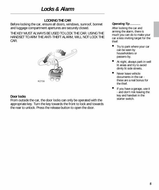
LOCKING THE CARBefore locking the car, ensure all doors, windows, sunroof, bonnetand luggage compartment apertures are securely closed.THE KEY MUST ALWAYS BE USED TO LOCK THE CAR. USING THEHANDSET TO ARM THE ANTI-THEFT ALARM, WILL NOT LOCK THECAR.
Door locksFrom outside the car, the door locks can only be operated with theappropriate key. Turn the key towards the front to lock and towardsthe rear to unlock. Press the release button to open the door.
Operating Tip ..........After locking the car andarming the alarm, there ismuch you can do to make yourcar a less inviting target for thethief:
• Try to park where your carcan be seen byhouseholders orpassers-by.
• At night, always park in welllit areas and try to avoiddimly lit side streets.
• Never leave vehicledocuments in the car -these are a real bonus forthe thief.
• If you have a garage, use it- and don’t risk leaving thekey and handset in thestarter switch.
H2156

Locks & Alarm
6
Interior lockingBoth doors can be locked from inside the car by moving the latchrearwards (move the latch forwards to unlock).
Luggage compartment lockTurn the appropriate key anti-clockwise to lock and clockwise tounlock. turn the handle anti-clockwise to open.
IMPORTANT
Using the key to operate thedoor and luggagecompartment locks, will NOTarm or disarm the anti-theftalarm system. Therefore,once armed, the alarm willsound if either door or theluggage compartment areunlocked with the key ANDopened - ALWAYS disarm thealarm by pressing the plainhandset button, BEFOREunlocking the car.
H2118
H2157

Locks & Alarm
7
ARMING THE ALARMThe handset has two buttons which, when pressed, send a codedradio signal to a receiver in the car. The ’padlock’ symbol buttonactivates, and the plain button de-activates the following securityfeatures:• The perimetric alarm (protects the door, bonnet, and luggage
compartment apertures).• Electronic engine immobilisation (described previously).
If the alarm soundsTo silence the alarm, press the plain handset button. Once activatedthe alarm will sound for approximately 30 seconds before switchingitself off, and can be triggered up to three times in total beforeneeding to be reset.
Anti-theft alarm indicator lightThe RED indicator light on the instrument panel flashes rapidlywhile the alarm system is arming itself.After approximately 10 seconds, the indicator light adjusts to aslower frequency, and continues flashing as an anti-theft deterrentuntil the alarm is next disarmed.If the alarm is armed when a door or other aperture is still open, theindicator light will not flash for the first 10 seconds but will flash atthe slower frequency. The alarm will still be armed, but the openaperture will not be protected. Close the open aperture; the alarmindicator light will flash rapidly and the alarm will automatically armitself as normal.
H2130

Locks & Alarm
8
KEY AND HANDSET NUMBERSYou have been supplied with two handsets and two sets of keys,comprising:• A large plastic handled key for operating the starter switch.• A small all-metal key which operates the door and luggage
compartment locks.• A larger all-metal key which operates the fuel filler cap lock.The starter key and handset number is stamped on a tag attached tothe key ring. The other key numbers are stamped onto the keys. Allkey numbers should be entered in the appropriate spaces providedon the Security Information card.If a key or handset is lost, contact a Rover dealer, who can supplyreplacement or additional keys and handsets.
WARNING!
Keep the SecurityInformation card, key tag,spare handset and keys in asafe place - NOT in the car.
H2155
Locks & Alarm
9
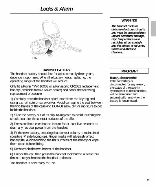
HANDSET BATTERYThe handset battery should last for approximately three years,dependent upon use. When the battery needs replacing, theoperating range of the handset will reduce.Only fit a Rover YWK 10003 or a Panasonic CR2032 replacementbattery (available from a Rover dealer) and adopt the followingreplacement procedure:1) Carefully prise the handset apart, start from the keyring endusing a small coin or screwdriver. Avoid damaging the seal betweenthe two halves of the case and DO NOT allow dirt or moisture to getinside the handset.2) Slide the battery out of its clip, taking care to avoid touching thecircuit board or the contact surfaces of the clip.3) Press and hold each button in turn for at least five seconds todrain any residual power from the handset.4) Fit the new battery, ensuring that correct polarity is maintained(positive ’+’ side facing up). Finger marks will adversely affectbattery life; avoid touching the flat surfaces of the battery or wipethem clean before fitting.5) Reassemble the two halves of the handset.6) Unlock the car, then press the handset lock button at least fourtimes to resynchronise the handset to the car.The handset is now ready for use.
WARNING!
The handset containsdelicate electronic circuitsand must be protected fromimpact and water damage,high temperatures andhumidity, direct sunlightand the effects of solvents,waxes and abrasivecleaners.
IMPORTANT
Battery disconnectionIf the car battery isdisconnected for any reason,the status of the securitysystem prior to disconnection,will be memorised andautomatically reset when thebattery is reconnected.
H2121

Seats
10
Forward/backward adjustmentLift the lever (1) and slide the seat into position. Make sure the seatis locked in position before driving.
Backrest adjustmentRotate the handwheel (2) to adjust.
Head restraint adjustmentLift or push down on the restraint, until level with the back of thehead.
Head restraint removalTurn the right hand mounting (3) a quarter turn anti-clockwise andpull the restraint upwards.
WARNING!
DO NOT adjust the seatswhen the car is moving.DO NOT allow front seatoccupants to travel with theseat backs reclined steeplyrearwards.
For Your Safety .........Where possible, adjust thehead restraint so that thecushion is level with the backof the head - NOT THE NECK!
2
1
3
H2127

Seats
11
Rear seat access leversLift the lever (1) upwards to fold the backrest forwards.Pull the lever (2) to fold the whole seat forwards.
For Your Safety .........Make sure the backrest issecure before driving.
1
2H2159
Seat Belts
12
SEAT BELT SAFETYThe seat belts supplied with your car are intended for use by adultsized occupants and must be used by one occupant only.Ensure that all passengers are securely strapped in at all times andbe sure to observe the following precautions:• Adjust seat belts to eliminate any slack. Do not pull the belt away
from the body - to be fully effective, the seat belt must remain infull contact with the body at all times.
• Fit the lap strap across the PELVIS (never across the abdomen),ensuring that the diagonal strap passes across the CHEST andSHOULDER.
• Always replace a seat belt assembly that has withstood thestrain of a severe vehicle impact, or if the webbing shows signsof fraying.
• DO NOT wear seat belts over hard, sharp or fragile items inclothing, such as pens, keys, spectacles etc.
• Where possible, use the seat belts to secure luggage carried onthe seats - in an accident, loose items can be thrown aroundinside the car, causing serious injury.
• In most countries, all occupants are required by law to wear aseat belt, unless they have been issued with a medicalexemption certificate. During pregnancy, women should wearthe lap belt across the hips below the baby, with the diagonalbelt passing across the shoulder, between the breasts and toone side of the baby - if in doubt consult a doctor.
For Your Safety .........Do not use a seat belt that istwisted or obstructed in anyway.Do not allow occupants totravel with the seat backsreclined steeply rearwards.
Do not allow foreign matter(particularly sugary food anddrink particles) to enter the seatbelt buckles - such substancescan render the bucklesinoperative.

Seat Belts
13
Fastening the beltPull the seat belt steadily across the body and, ensuring thewebbing is not twisted, insert the metal tongue plate into theappropriate buckle - a ’click’ indicates that the belt is securelylocked.
Releasing the beltPress the red button attached to the seat belt buckle.
CHILD SEATSFor safety, it is very important that all infants and young childrenare restrained in a suitable child safety seat. For further informationon child safety seats available for your car, please contact yourRover dealer.
For Your Safety .........Where possible, rear seatpassengers should adjust theirposition (moving nearer to orfurther away from the centre ofthe car) to enable the seat beltwebbing to cross the shoulderwithout pressing on the neck.
WARNING!
Ensure that all seat beltsare worn correctly - animproperly worn seat beltincreases the risk of deathor serious injury in theevent of a collision.Do not allow a baby or childto be carried on the lap - inan accident, it will beimpossible to hold on to thechild.
Accident statistics showthat children are safer whenproperly restrained in therear seating positions thanin the front.
Never leave a childunattended in the car.
H2123

Seat Belts
14
Caring for seat beltsRegularly inspect the belt webbing for signs of fraying, cuts andwear, also pay particular attention to the condition of the fixingpoints and adjusters.Avoid contaminating the webbing with polish, oil and chemicals(see ’Cleaning & car care’).
Three tests for checking seat belts1. With the seat belt fastened, give the webbing near the buckle a
quick upward pull - the buckle should remain securely locked.2. With the seat belt unfastened, unreel the webbing to the limit of
its travel. Check that unreeling is free from snatches and snags.3. With the webbing half unreeled, hold the tongue plate and give
it a quick forward pull - the mechanism must lock automaticallyand prevent any further unreeling.
If a seat belt should fail any of these tests, contact your dealerimmediately.
SEAT BELT PRE-TENSIONERSThe seat belt pre-tensioners act in conjunction with the airbag SRSsystem and provide additional protection in the event of a severefrontal impact on the vehicle (see ’Airbag SRS’). The pre-tensionersautomatically retract the seat belts fitted to the front seats. Thisreduces any slack in both the lap and diagonal portions of the belts,thereby reducing forward movement of the belt wearer in the eventof a severe frontal collision.The airbag SRS warning light on the instrument panel, described onthe following page, will alert you to any malfunction of the seat beltpre-tensioners.
WARNING!
Always replace a seat beltassembly that haswithstood the strain of asevere vehicle impact, orone where the webbingshows signs of fraying.
For Your Safety .........DO NOT wear seat belts fittedwith pre-tensioners directlyover bare skin. In the event of acollision, friction burns couldoccur when the pre-tensionersare activated.
Operating Tip ..........If the pre-tensioners have beenactivated, the seat belts will stillfunction as conventionalrestraints. If it is necessary forthe car to be driven to a dealerfor repair, the seat belts mustbe worn.

Airbag SRS
15
The airbag supplementary restraint system (SRS) providesadditional protection for the driver in the event of a SEVEREFRONTAL IMPACT ON THE VEHICLE.
Airbag SRS warning lightThe warning light, mounted on the instrument panel, will illuminatefor approximately six seconds when the starter switch is turned toposition ’II’. The warning light will also alert you to any malfunctionof the airbag SRS. The system should be checked by your Roverdealer if any of the following symptoms occur:• The warning light fails to illuminate when the starter switch is
turned to position ’II’.• The warning light fails to extinguish after approximately six
seconds.• The warning light flashes or illuminates continuously while the
car is being driven.
For Your Safety .........Always remember; the airbagSRS provides ADDITIONALprotection in a frontal impactonly; it does not replace theneed to wear a seat belt.Inflation and deflation of theairbag take place very quicklyand it will not protect againstthe effects of secondaryimpacts that may occur.
H2141

Airbag SRS
16
How the airbag SRS worksIn a frontal collision, a sensor monitors the force of the impact todetermine whether the airbag should be inflated. The airbag,contained within the steering wheel centre pad, will inflate inSEVERE frontal collisions only, It will NOT inflate in the event ofside or rear impacts, roll over accidents, or minor frontal impacts.Inflation is instantaneous and accompanied by a loud noise andtraces of smoke and powder, none of which are indicative of anairbag malfunction.After inflation, the airbag module deflates immediately so that thedriver’s visibility is not impaired.
For Your Safety .........After inflation, some airbagcomponents are hot - DO NOTtouch until they have cooled.
WARNING!
An inflating airbag cancause facial abrasions andother injuries. Minimise therisk of injury by ensuringthe driver is wearing theseat belt and is seatedcorrectly with the seat asfar back as is practical.DO NOT attach accessoryitems to the airbag modulecover (steering wheelcentre pad), which couldinterfere with the inflationof the airbag or, if theairbag inflates, bepropelled inside the carcausing injury to theoccupants.
H2148B

Airbag SRS
17
Service informationAfter 10 years from the date of registration (or installation date of areplacement airbag SRS), some components will need to bereplaced by a Rover dealer (see airbag module replacement dateshown on page 2 of the Service Portfolio book), who should stampand sign the appropriate page once the work is completed.In addition, ALWAYS contact your Rover dealer if;• the airbag inflates.• the front of the car is damaged (even if the airbag has not
inflated).• any part of the airbag module cover shows signs of cracking or
damage.If you sell your car, be sure to inform the new owner that the carhas an airbag SRS, and of the airbag module replacement dateshown in the Service Portfolio.If the car is to be scrapped; uninflated airbags are potentially verydangerous and must be safely deployed in a controlled environmentby qualified personnel before a vehicle is scrapped.
WARNING!
DO NOT service, repair,replace, modify or tamperwith any part of the airbagSRS or wiring in the vicinityof an airbag SRScomponent; this couldcause the system toactivate, resulting inpersonal injury.The components of theairbag SRS are sensitive toelectrical and physicalinterference; therefore,ALWAYS seek theassistance of a Roverdealer to carry out any ofthe following:
Removal or repair of anywiring or component in thevicinity of the airbag SRScomponents (yellow wiringharness), including thesteering wheel, steeringcolumn and instrumentpanel.
Installation of electronicequipment such as a mobilephone, two-way radio orin-car entertainmentsystem.
Attachment of accessoriesto, or modification of, thefront of the car.

Mirrors
18
Exterior mirrorsAdjust the exterior mirrors to give the required view from thedriver’s seat position.
Interior mirrorAdjust the interior mirror to give the required view from the driver’sseat.The mirror can be dipped to reduce headlight glare from followingvehicles;• Move the lever at the bottom of the mirror towards the
windscreen.• Pull the lever back to restore normal visibility.
For Your Safety .........The view reflected in a ’dipped’interior mirror can sometimesconfuse the driver as to theprecise position of followingvehicles. Remember to takeadditional care!
H2143
H2111

Mirrors
19
Vanity mirrorTo use the vanity mirror, pull down the passenger’s sun visor.
Operating Tip ..........Always return the sun visor toits stowed position when not inuse - the sun, reflected in thevanity mirror, could scorch theseats.
H2129

Windows
20
Front windowsTurn the handle to open or close window as required.
Rear ventilator windows (illustrated)To open, pull the catch forwards, then push outwards (as arrowed).To close, pull the centre of the catch inwards, then push rearwardsuntil the catch is felt to ’snap’ into the locked position.
For Your Safety .........Ensure that children are keptclear while operating thewindows.
H2158
Sunroof
21
SUNROOF(if fitted)
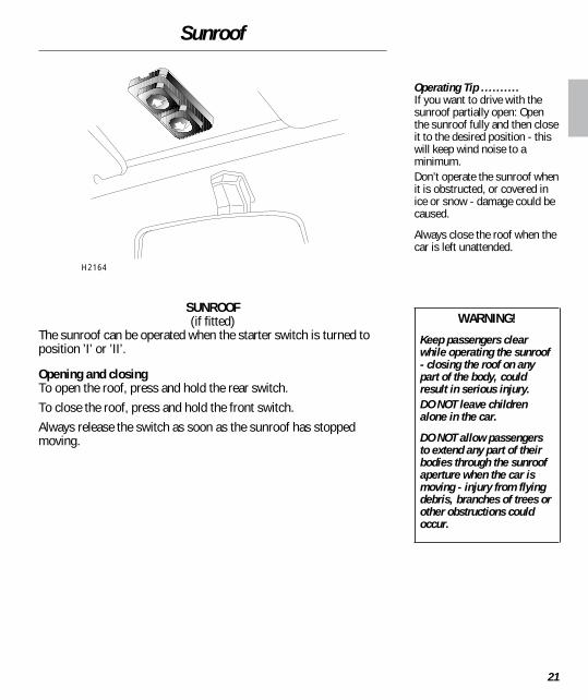
The sunroof can be operated when the starter switch is turned toposition ’I’ or ’II’.
Opening and closingTo open the roof, press and hold the rear switch.To close the roof, press and hold the front switch.Always release the switch as soon as the sunroof has stoppedmoving.
Operating Tip ..........If you want to drive with thesunroof partially open: Openthe sunroof fully and then closeit to the desired position - thiswill keep wind noise to aminimum.Don’t operate the sunroof whenit is obstructed, or covered inice or snow - damage could becaused.
Always close the roof when thecar is left unattended.
WARNING!
Keep passengers clearwhile operating the sunroof- closing the roof on anypart of the body, couldresult in serious injury.DO NOT leave childrenalone in the car.
DO NOT allow passengersto extend any part of theirbodies through the sunroofaperture when the car ismoving - injury from flyingdebris, branches of trees orother obstructions couldoccur.
H2164
Sunroof
22
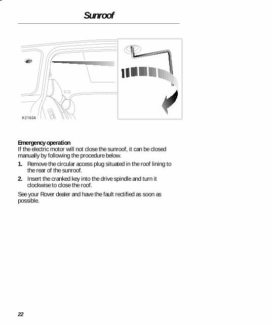
Emergency operationIf the electric motor will not close the sunroof, it can be closedmanually by following the procedure below.1. Remove the circular access plug situated in the roof lining to
the rear of the sunroof.2. Insert the cranked key into the drive spindle and turn it
clockwise to close the roof.See your Rover dealer and have the fault rectified as soon aspossible.
H2160A
Heating & Ventilation
23
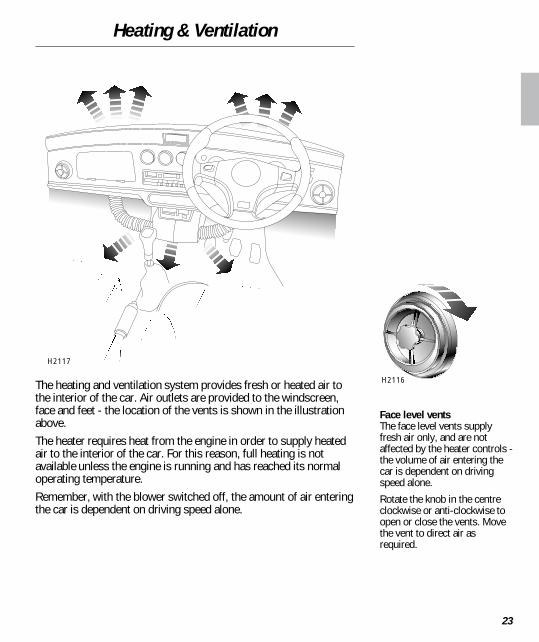
The heating and ventilation system provides fresh or heated air tothe interior of the car. Air outlets are provided to the windscreen,face and feet - the location of the vents is shown in the illustrationabove.The heater requires heat from the engine in order to supply heatedair to the interior of the car. For this reason, full heating is notavailable unless the engine is running and has reached its normaloperating temperature.Remember, with the blower switched off, the amount of air enteringthe car is dependent on driving speed alone.
Face level ventsThe face level vents supplyfresh air only, and are notaffected by the heater controls -the volume of air entering thecar is dependent on drivingspeed alone.
Rotate the knob in the centreclockwise or anti-clockwise toopen or close the vents. Movethe vent to direct air asrequired.
H2117
H2116
Heating & Ventilation
24
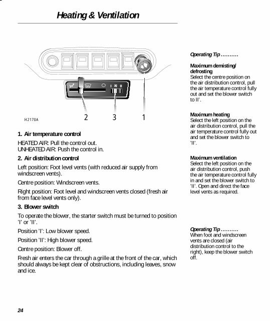
1. Air temperature controlHEATED AIR: Pull the control out.UNHEATED AIR: Push the control in.2. Air distribution controlLeft position: Foot level vents (with reduced air supply fromwindscreen vents).Centre position: Windscreen vents.Right position: Foot level and windscreen vents closed (fresh airfrom face level vents only).3. Blower switchTo operate the blower, the starter switch must be turned to position’I’ or ’II’.Position ’I’: Low blower speed.Position ’II’: High blower speed.Centre position: Blower off.Fresh air enters the car through a grille at the front of the car, whichshould always be kept clear of obstructions, including leaves, snowand ice.
Operating Tip ..........
Maximum demisting/defrostingSelect the centre position onthe air distribution control, pullthe air temperature control fullyout and set the blower switchto II’.
Maximum heatingSelect the left position on theair distribution control, pull theair temperature control fully outand set the blower switch to’II’.
Maximum ventilationSelect the left position on theair distribution control, pushthe air temperature control fullyin and set the blower switch to’II’. Open and direct the facelevel vents as required.
Operating Tip ..........When foot and windscreenvents are closed (airdistribution control to theright), keep the blower switchoff.
H2170A 2 3 1
Interior Equipment
25
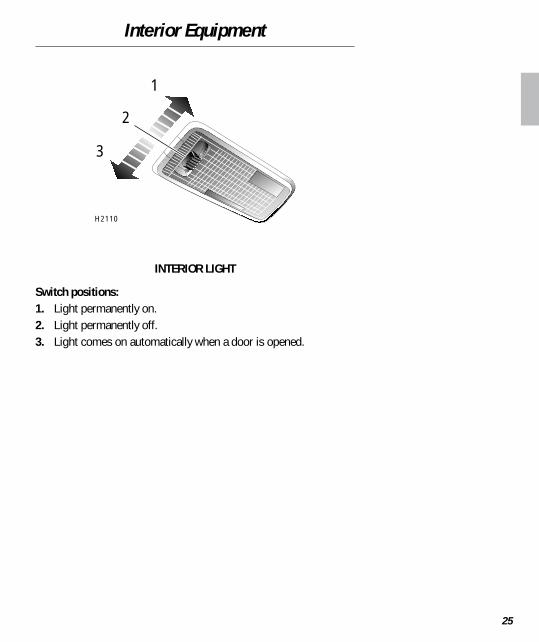
INTERIOR LIGHT
Switch positions:1. Light permanently on.2. Light permanently off.3. Light comes on automatically when a door is opened.
1
2
3
H2110
Interior Equipment
26
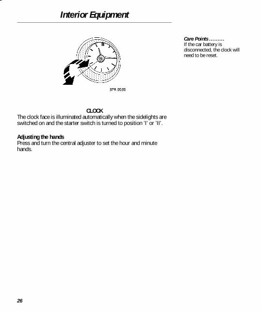
CLOCKThe clock face is illuminated automatically when the sidelights areswitched on and the starter switch is turned to position ’I’ or ’II’.
Adjusting the handsPress and turn the central adjuster to set the hour and minutehands.
Care Points .........If the car battery isdisconnected, the clock willneed to be reset.

Interior Equipment
27
GLOVEBOXPress the upper edge of the glovebox lid to open.
ASHTRAYPush the front of the ashtray on the right hand side to open.To remove for emptying, open the ashtray, then carefully lever thefront of the tray upwards to disengage the lower pivot (arrowed inillustration). The ashtray can then be pulled out.Replacement is a reversal of this process.
For Your Safety .........DON’T drive with the gloveboxopen. An open glovebox couldcause injury to a front seatpassenger in the event of acollision.
WARNING!
Ashtrays are fire hazards -DON’T use for waste paperor other combustiblematerial.
H2112
H2166

In-Car Entertainment
28
RADIO AERIALYour car is equipped with a detachable mast aerial mounted on theroof; unscrew to remove.Always check the available headroom and, if necessary, adjust theangle of the aerial before entering or leaving a garage or car parkwith insufficient headroom.
RADIO/CASSETTE PLAYERFull operating instructions for the audio equipment fitted asstandard to your car, are contained in the ’In-car Entertainment’book in the vehicle literature pack.
Care Points .........ALWAYS unscrew and removethe aerial before entering anautomatic car wash.
H2137

Load Carrying
29
Rear window shelfHard, heavy or pointed objects should not be carried on the rearwindow shelf - they may cause personal injury or damage the rearwindow itself during a sudden manoeuvre.
Roof racksMake sure that you only fit a roof rack that is approved for your car.Your Rover dealer can provide details of all Rover approved roofracks.The total roof rack load (including the weight of the roof rack), mustnever exceed the figure given under ’Weights’ in the ’Technical data’section of this handbook. Owners should be aware that, if the roofrack is to be loaded to its maximum, then the carrying capacity ofthe car interior must be limited to a maximum of three adultpassengers only, with no luggage in the rear of the car or the boot.When loading the roof rack, make sure that all loads are evenlydistributed and properly secured within the periphery of the rack.
TowingYour Mini is not suitable for towing.
For Your Safety .........Do not carry unsecuredequipment, tools or luggageinside the car, that could move,causing personal injury in theevent of an accident oremergency manoeuvre. Securelarger objects with a seat belt.A loaded roof rack can reducethe stability of your car,particularly when cornering andencountering crosswinds.

Instruments
30
1. SpeedometerIndicates road speed in miles per hour and/or kilometres per hour.2. Total distance recorder (odometer)Indicates the total distance travelled by the car.3. Fuel gaugeThe pointer indicates the quantity of fuel in the tank once the starterswitch is turned on.4. Coolant temperature gaugeThe gauge indicates the temperature of the engine coolant. As theengine warms up, the pointer will rise from the BLUE (’C’ - cold)mark to the mid-point of the gauge, where it should remain whilethe engine is operating at its normal temperature.If the pointer reaches the RED (’H’ - hot) mark, the coolant is toohot and severe engine damage could result; stop the car as soon assafety permits and seek qualified assistance.5. TachometerIndicates engine speed in revolutions per minute (x 1000). Toprotect the engine from damage, NEVER allow the engine speed toexceed 6,000 revolutions per minute.
Operating Tip ..........Driving on twisting or hillyroads may adversely affect theaccuracy of the fuel gauge. It isadvisable to check the fuel levelwhen the car is travelling on astraight level road.
WARNING!
Never allow the car to runout of fuel (the resultantmisfire could damage thecatalytic converter).
1 2 3 4 5H2151

Instruments
31
6. Voltmeter (if fitted)Indicates battery voltage. During normal driving, the pointer shouldregister between 12 and 15 volts depending on road speed andelectrical loads.If the pointer falls into the lower RED zone while driving, the batteryis receiving insufficient charge. Switch off unnecessary electricalequipment, and if the pointer remains in the RED zone seekqualified assistance.If the pointer enters the upper RED zone, this indicates a seriousfault with the charging system; seek qualified assistance urgently.7. Oil temperature gauge (if fitted)Indicates the temperature of the engine oil. For gentle and moderatespeed driving, expect the pointer to rest between 90° C and 120° C(2nd and 3rd graduations on the gauge). Sustained high speedmotoring may cause the temperature to rise to 150° C (4thgraduation on the gauge - on the edge of the RED zone). If thepointer enters the RED zone, you must reduce road speedimmediately and drive GENTLY until the temperature falls below150° C. If the oil temperature does not fall, stop the car as soon assafety permits and seek qualified assistance.
3
6 7H2150

Warning Lights
32
1. Low oil pressure - REDIlluminates as a bulb check when the starter switch is turned toposition ’II’ and extinguishes when the engine is started. If the lightremains on, or illuminates whilst driving, stop the car as soon assafety permits and switch off the engine immediately. Seek qualifiedassistance before driving.
2. Battery charging - REDIlluminates as a bulb check when the starter switch is turned toposition ’II’ and extinguishes when the engine is started. If the lightremains on, or illuminates whilst driving, a fault with the batterycharging system is indicated. Seek qualified assistance urgently.
3. Airbag supplementary restraint system - REDThe light illuminates when the starter switch is turned to position ’II’and extinguishes within approximately six seconds. If the light failsto illuminate, or illuminates again after the six second period, thesystem is faulty - seek qualified assistance urgently.
4. Anti-theft alarm indicator - REDIlluminates in conjunction with the anti-theft alarm system (see’Anti-theft alarm’).
4 3 6 55
12H2153A

Warning Lights
33
5. Direction indicators - GREENThe left or right warning light flashes in time with the left or rightdirection indicator lights, whenever they are operated. If eitherwarning light fails to illuminate, or flashes very rapidly, this meansthat one of the indicator lights is not operating.
6. Headlight main beam - BLUEIlluminates when the headlights are switched to main beam.
Operating Tip ..........When the hazard warning lightsare operated, both directionindicator warning lights willflash together.

Starting & Driving
34
STARTER SWITCH & STEERING LOCKThe starter switch uses the following sequence of key positions tooperate the steering lock, electrical circuits and starter motor.
’0’ - Steering lockedWith the key removed, the steering column will be locked and thelighting circuits operational.
’I’ - Steering unlockedTurn to position ’I’ to unlock the steering. The radio/cassette playercan now be operated.
’II’ - Electrical circuits onWith the switch in position ’II’, all instruments and electricalsystems are operational.
’III’ - Starter motor operatesTurn to position ’III’ to operate the starter motor; release the key assoon as the engine starts (the key will automatically return toposition ’II’).
WARNING!
Once the steering lock isengaged, it is impossible tosteer the car.DO NOT remove the key, orturn the starter switch toposition ’0’, while the car isin motion.
Operating Tip ..........Unlocking the steeringAfter inserting the key, a smallmovement of the steeringwheel will help to disengage thelock before turning the switchto position ’I’.
Locking the steeringAfter removing the starter key,turn the steering wheel slightly- you will hear the lock ’click’into engagement.
H2149A

Starting & Driving
35
Starting the engine1. Check that the handbrake is on and the gear lever is in neutral.2. Switch off all unnecessary electrical equipment.3. Turn the starter switch to position ’III’ and release the key as
soon as the engine has started.Do not press the accelerator pedal while starting and do not operatethe starter for more than 10 seconds at a time. Wait for at least 10seconds before trying to start the engine again.
Cold climatesIn cold climates, engine cranking times may increase - reduce theload on the battery by depressing the clutch while operating thestarter motor.
Warming upIn the interests of fuel economy, drive the car soon after starting;remember that harsh acceleration or labouring the engine beforenormal operating temperatures have been reached, can damage theengine.
Switching off the engineAfter stopping the car, always apply the handbrake and selectneutral before releasing the foot brake and switching off the engine.Depending on the engine temperature, the cooling fan maycommence operating after the engine is switched off, and continueoperating for several minutes. This is normal, and not a cause forconcern.
WARNING!
Never start, or leave theengine running, in anunventilated building -exhaust gases arepoisonous and containcarbon monoxide, whichcan cause unconsciousnessand may even be fatal.
Care Points .........Catalytic converters can bedamaged if the wrong fuel isused, or if an engine misfireoccurs. Before starting theengine, you should be aware ofthe precautions detailed under’Catalytic converter’.Continued use of the starter willnot only discharge the battery,but may damage the startermotor and the catalyticconverter.
Operating Tip ..........In freezing conditions, or whenthe battery is in a low state ofcharge, depress the clutchwhile operating the starter; thiswill reduce the load on thebattery.

Starting & Driving
36
RUNNING-INThe engine, gearbox, brakes and tyres need time to ’bed-in’ andadjust to the demands of everyday motoring. During the first 600miles (1,000 km) it is essential that you drive with consideration forthe running-in process and heed the following advice:• Do not allow the engine to exceed 3,000 rev/min in any gear.• Do not exceed 60 mph (95 km/h).• Do not operate at full throttle in any gear.• Do not allow the engine to labour in any gear.• Avoid heavy braking.After the running-in distance has been completed, engine speedsmay be gradually increased.
FUEL ECONOMYFuel consumption is influenced by two major factors:• How your car is maintained.• How you drive.To obtain optimum fuel economy, it is essential that your car ismaintained in accordance with the manufacturer’srecommendations, but above all, the way in which you drive is mostimportant. Note the operating tips alongside.
Operating Tip ..........The following hints may helpyou to obtain optimum fuelconsumption:
• Avoid unnecessary short,start-stop, journeys.
• Avoid fast starts. Alwaysaccelerate smoothly andgently from rest.
• Do not drive in low gearsfor longer than necessary.
• Decelerate gently and avoidsudden and heavy braking.
• Anticipate obstructions wellin advance, and adjust yourspeed accordingly,

Catalytic Converter
37
The exhaust system on your car incorporates a catalytic converterwhich converts poisonous exhaust emissions into environmentallyless harmful gases, thereby reducing pollution.Catalytic converters are easily damaged through improper use, sobe sure to take notice of the following precautions to minimise thechance of accidental damage.
Fuel• Only use 95 RON UNLEADED petrol to EN 228 specification.
Using leaded fuel will destroy the catalyst.• Never allow the car to run out of fuel - this could cause a misfire
which could damage the catalyst.
Starting• Do not continue to operate the starter after a few failed attempts,
seek qualified assistance.• Do not operate the starter if an engine misfire is suspected and
do not attempt to clear a misfire by pressing the acceleratorpedal.
• Do not attempt to push or tow start the car.
WARNING!
Exhaust temperatures canbe extremely high, do notpark on ground wherecombustible materials suchas dry grass or leaves couldcome in contact with theexhaust system - in dryweather a fire could result.
H2133A

Catalytic Converter
38
Driving• Do not overload or excessively ’rev’ the engine.• Do not switch off the engine when the car is in motion with a
drive gear selected.• Consult your dealer if you think your car is burning too much oil,
as this will progressively reduce catalyst efficiency.• If a misfire is suspected, or the car lacks power while driving,
provided the engine has reached its normal operatingtemperature, it may be driven SLOWLY (at risk of catalystdamage) to a Rover dealer for assistance.
• DO NOT run the engine with a spark plug or lead removed, oruse any device that requires an insert into a spark plug.
• Do not drive the car on terrain likely to subject the underside ofthe car to heavy impacts.
IMPORTANT
Any engine misfire, loss ofengine performance or enginerun-on, could seriouslydamage the catalyticconverter. For this reason, itis vital that unqualifiedpersons do not tamper withthe engine, and that regularmaintenance is carried out bya Rover dealer in accordancewith the service interval planin the Service Portfolio book.
Gearbox
39
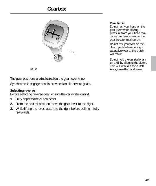
The gear positions are indicated on the gear lever knob.Synchromesh engagement is provided on all forward gears.
Selecting reverseBefore selecting reverse gear, ensure the car is stationary!1. Fully depress the clutch pedal.2. From the neutral position move the gear lever to the right.3. While lifting the lever, ease it to the right before pulling it fully
rearwards.
Care Points .........Do not rest your hand on thegear lever when driving -pressure from your hand maycause premature wear to thegear selector mechanism.Do not rest your foot on theclutch pedal when driving -excessive wear to the clutchwill result.
Do not hold the car stationaryon a hill by slipping the clutch.This will wear out the clutch.Always use the handbrake.H2146

Fuel System
40
FUEL FILLINGThe fuel filler is located in the rear left hand wing. Insert the largerall-metal key in the lock, turn it anti-clockwise and allow anypressure inside the tank to escape, before removing the cap.Remember to lock the cap after refuelling.The filler tube is designed to accept a narrow filler nozzle of the typefound on pumps that deliver only unleaded fuel. A flap lies acrossthe filler neck; insert the nozzle sufficiently to fully open the flapbefore filling.Fill the tank slowly until the filler nozzle automatically cuts-off thefuel supply. DO NOT attempt to fill the tank beyond this point, orspillage could result due to expansion of the fuel.
Grade of fuelThe RON (octane rating) of petroleum commonly available at garageforecourts, will vary in different countries. The 95 RON unleadedspecification, is a minimum requirement and can be safelyexceeded. However, lower octane fuels may cause serious damageto the engine.
Empty fuel tankNEVER allow the car to run out of fuel - the resultant misfire maydestroy the catalytic converter. In the event of the fuel tank runningdry, contact your Rover dealer before attempting to start the engine.
For Your Safety .........Petroleum gases are highlyinflammable and, in confinedspaces, are also extremelyexplosive. Always take carewhen refuelling:
• Switch off the engine.
• Do not smoke or use anaked flame.
• Avoid spilling fuel.
• Do not overfill the tank.
Fuel specification:95 RON unleaded petrol to EN228 specification
WARNING!
USE ONLY UNLEADEDPETROL. Serious damage tothe catalytic converter willoccur, if leaded fuel isused.DO NOT fully fill the tank ifthe car is to be parked on aslope in direct sunlight, orhigh ambient temperature -expansion of the fuel couldcause spillage.
H2152

Fuel System
41
FUEL CUT-OFF SWITCHThe fuel cut-off switch is a safety device which, in the event of acollision or sudden impact, automatically cuts off the fuel supply.The switch is located on the left hand side of the enginecompartment, mounted on the bulkhead. After the switch has beenactivated, it must be reset by pressing the rubber top before theengine can be restarted.
WARNING!
ALWAYS check for fuelleaks before resetting thefuel cut-off switch.
H2103

Wipers
42
WIPER CONTROLSThe wipers and washers will only operate when the starter switch isturned to position ’I’ or ’II’.
Single wipePull the lever down and release.
NOTE: With the lever held down, the wipers will operate at highspeed until it is released.
Intermittent wipeTurn switch to first position.
Normal speed wipeTurn switch to second position.
Fast speed wipeTurn switch to third position.
Windscreen washerPull the lever towards the steering wheel. The washers will operatefor as long as the lever is held in this position.
NOTE: The wipers operate automatically during windscreenwashing.
Care Points .........DO NOT operate the wipers ona dry screen.
DO NOT operate the wiperswith the bonnet raised.
In freezing or very hotconditions, ensure that theblades are not frozen or stuckto the glass before beingoperated.
In winter, remove snow or icefrom around the arms andblades, including the wipedarea of the windscreen.
H2145

Lights & Indicators
43
Direction indicatorsThe direction indicators will only operate with the starter switchturned to position ’II’.• For a right-hand turn, push the lever up.• For a left-hand turn, push the lever down.The appropriate warning light on the instrument panel will flashGREEN while the direction indicators are operating. The indicatorswill cancel automatically once a turn has been completed.
Side, tail and instrument panel lightsTurn the switch to the first position.
HeadlightsTurn the switch to the second position.
Headlight - main, dipped beam and flashPull the lever fully towards the steering wheel to change headlightbeams (the BLUE warning light on the instrument panel illuminateswhen the headlights are on main beam).Pull the lever half-way towards the steering wheel to briefly flashthe headlights.
Driving lamps (if fitted)The driving lamps will illuminate automatically when the headlightsmain beams are switched on.
Operating Tip ..........Hold the direction indicatorlever half-way up or down toindicate a lane change.The side, tail and headlightsoperate with the starter switchin any position.
H2147
Lights & Indicators
44
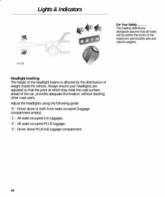
Headlight levellingThe height of the headlight beams is affected by the distribution ofweight inside the vehicle. Always ensure your headlights areadjusted so that the point at which they meet the road surfaceahead of the car, provides adequate illumination, without dazzlingother road users.Adjust the headlights using the following guide:’0’ - Driver alone or both front seats occupied (luggagecompartment empty).’1’ - All seats occupied (no luggage).’2’ - All seats occupied PLUS luggage.’3’ - Driver alone PLUS full luggage compartment.
For Your Safety .........The loading definitionsalongside assume that all loadswill be within the limits of themaximum permissible axle andvehicle weights.
H2136
Switches
45
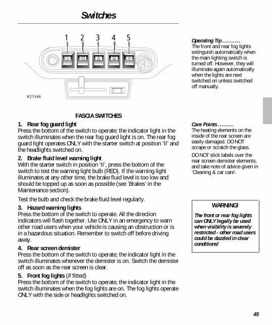
FASCIA SWITCHES1. Rear fog guard lightPress the bottom of the switch to operate; the indicator light in theswitch illuminates when the rear fog guard light is on. The rear fogguard light operates ONLY with the starter switch at position ’II’ andthe headlights switched on.2. Brake fluid level warning lightWith the starter switch in position ’II’, press the bottom of theswitch to test the warning light bulb (RED). If the warning lightilluminates at any other time, the brake fluid level is too low andshould be topped up as soon as possible (see ’Brakes’ in theMaintenance section).Test the bulb and check the brake fluid level regularly.3. Hazard warning lightsPress the bottom of the switch to operate. All the directionindicators will flash together. Use ONLY in an emergency to warnother road users when your vehicle is causing an obstruction or isin a hazardous situation. Remember to switch off before drivingaway.4. Rear screen demisterPress the bottom of the switch to operate; the indicator light in theswitch illuminates whenever the demister is on. Switch the demisteroff as soon as the rear screen is clear.5. Front fog lights (if fitted)Press the bottom of the switch to operate; the indicator light in theswitch illuminates when the fog lights are on. The fog lights operateONLY with the side or headlights switched on.
Operating Tip ..........The front and rear fog lightsextinguish automatically whenthe main lighting switch isturned off. However, they willilluminate again automaticallywhen the lights are nextswitched on unless switchedoff manually.
Care Points .........The heating elements on theinside of the rear screen areeasily damaged. DO NOTscrape or scratch the glass.DO NOT stick labels over therear screen demister elements,and take note of advice given in’Cleaning & car care’.
WARNING!
The front or rear fog lightscan ONLY legally be usedwhen visibility is severelyrestricted - other road userscould be dazzled in clearconditions!
1 2 3 4 5
H2154A

Brakes
46
BRAKING SYSTEMThe hydraulic braking system operates through dual circuits; if onecircuit should fail, the other will continue to function. However, inthe event of a brake failure where only one circuit is operational, thecar should only be driven slowly to the nearest Rover dealer -exercise EXTREME CAUTION and be aware that much greater pedaleffort and longer stopping distances will be required if one circuithas failed.The braking system is servo assisted. This means that if the enginestops running, servo assistance will be lost, resulting in greaterpedal effort and longer stopping distances.
Brake padsBrake pads and linings require a period of bedding in. During therunning-in period (see ’Starting & Driving’), avoid situations whereheavy braking is required.Remember, regular servicing is vital to ensure that brakecomponents are examined for wear at the correct intervals andchanged whenever necessary to ensure optimum safety andperformance.
Brake fluid warning lightIf the warning light (in the switch) illuminates while driving, thebrake fluid level is too low; stop the car as soon as safety permitsand top up the brake fluid reservoir (refer to the ’Maintenance’section).You should regularly test the brake fluid warning light by pressingthe bottom of the switch. If the switch is operating correctly, thelight in the switch will illuminate.
WARNING!
DO NOT rest your foot onthe brake pedal whiledriving; this may overheatthe brakes, reducing theirefficiency and causingexcessive wear.If the brake warning lightilluminates while driving,stop the car as soon assafety permits and seekqualified assistance beforecontinuing.
NEVER move the carwithout the engine running,servo assistance may notbe available. Without servoassistance, the brakes willstill function, but greaterpedal pressure and longerstopping distances will berequired.

Brakes
47
HANDBRAKEThe handbrake operates on the rear wheels only and should notrequire adjustment. To apply the handbrake, pull the lever up.Always apply the handbrake fully whenever you park the car.To release, pull the lever up slightly, depress the button (arrowed inillustration) and fully lower the lever.
WARNING!
DO NOT drive with thehandbrake applied, thiscould damage the rearbrakes and axles.
Operating Tip ..........While applying the handbrake,hold the button in to minimisewear on the ratchet.
H2109

Maintenance
48
ROUTINE SERVICINGThe safety, reliability and performance of your car will depend partlyon how it is maintained.Maintenance is the owner’s responsibility; make sure that all routineservices and warranty inspections are carried out by a Rover dealerat the recommended intervals shown in the Service Portfolio book.You will find this book in the literature pack.The Service Portfolio book also includes a Service Record section,which enables a record to be kept of all the routine services carriedout on the car - ensure your dealer endorses the book after eachservice.
OWNER MAINTENANCEIn addition to the routine services and warranty inspections referredto above, a number of simple checks must be carried out morefrequently. These are listed alongside. You can do these yourselfand advice is given on the following pages.
Daily Checks ..........• Operation of lights, horn,
direction indicators, wipers,washers and warninglights.
• Operation of seat belts andbrakes.
• Look for fluid depositsbeneath the car that mayindicate a leak.
Weekly Checks ..........• Engine oil level.
• Coolant level.
• Brake fluid level.
• Clutch fluid level.
• Screen washer fluid.
• Tyre pressures andcondition.

Maintenance
49
SAFETY IN THE GARAGEIf you need to carry out maintenance, observe the followingsafety precautions at all times:• Keep your hands, tools and clothing away from drive belts and
pulleys.• If the car has been driven, DO NOT TOUCH exhaust and cooling
system components until the engine has cooled.• DO NOT TOUCH electrical leads or components while the engine
is running, or with the starter switch turned on.• NEVER leave the engine running in an unventilated area -
exhaust gases are poisonous and extremely dangerous.• DO NOT work beneath the car with the wheel changing jack as
the only means of support.• Ensure sparks and naked lights are kept away from the engine
and luggage compartments.• Remove wrist bands and jewellery before working in the engine
compartment.• DO NOT allow battery leads or terminals to make contact with
tools or metal parts of the car.
Poisonous fluidsFluids used in motor vehicles are poisonous and should not beconsumed or brought into contact with open wounds. Theseinclude: battery acid, anti-freeze, brake and clutch fluid, petrol,engine oil and windscreen washer additives. Obey all instructionsprinted on labels and containers.
WARNING!
Cooling fans may operateafter the engine is switchedoff. Keep clear of all fanswhile working in the enginecompartment.
Care Points .........Prolonged contact with engineoil may cause serious skindisorders, including dermatitisand cancer of the skin. Washthoroughly after contact.It is illegal to pollute drains,water courses or soil. Useauthorised waste disposal sitesto dispose of used oil and toxicchemicals.

Bonnet Opening
50
1. From inside the car, pull the bonnet release lever.2. Push the safety catch lever away from the front of the bonnet
and raise the bonnet.3. Unclip the support stay.4. Fit the support stay into the bracket as shown.
Closing the bonnetRaise the bonnet slightly to release the support stay, then replacethe stay in the clip. Lower the bonnet onto the catch, then use thepalms of both hands to press the bonnet fully down to engage thecatch.
WARNING!
DO NOT drive with thebonnet retained by thesafety catch alone.
For Your Safety .........After closing the bonnet, checkthat the lock is fully engaged byattempting to lift the front edgeof the bonnet. This should befree from all movement.
H2162
3 4
21

Engine Compartment
51
WARNING!
While working in the enginecompartment, alwaysobserve the safetyprecautions listed under’Safety in the garage’ on aprevious page.
1. Engine oil filler2. Engine oil dipstick3. Fusebox (engine
compartment)4. Brake reservoir5. Clutch reservoir6. Fuel cut-off switch7. Cooling system reservoir
12
3
4 5 6
7
H2107

Engine
52
OIL LEVEL CHECK & TOP-UPCheck the oil level when the car is on level ground with the engineswitched off. If the engine is warm, wait for at least two minutesbefore checking the level.1. Pull out the dipstick and wipe the blade clean.2. Re-insert the dipstick and withdraw again to check the level.3. If the level is at or near the ’MIN’ mark, twist to release the oil
filler cap and add oil to bring the level close to the ’MAX’ mark.4. After adding oil, wait for at least two minutes, then recheck the
level, adding more oil if necessary.5. Finally, replace the dipstick and filler cap.
DO NOT fill above the ’MAX’ mark!
WARNING!
Driving with the oil levelbelow the ’MIN’ mark willdamage the engine.
Oil specification:10W/30 engine oil, meetingRES.22.OL.G4 or ACEA A2:96.
Suitable for use intemperatures between-20° C to +30° C (if climatictemperature falls outside theselimits, seek advice from yourdealer).
Most major oil companiesproduce engine oils to theabove specification.
Operating Tip ..........Check the oil when you fill upwith fuel (refuel first, thencheck the oil - this allows timefor the oil to drain into thesump before you check thelevel).
H2104

Cooling System
53
COOLANT CHECK & TOP-UPCheck the coolant level weekly when the engine is cold and, ifnecessary, top-up with a mixture of anti-freeze and water, so thatthe coolant is level with the horizontal seam half-way up thereservoir.If the level falls appreciably during a short period, this may indicatea leak or engine overheating, in which case arrange for a Roverdealer to examine the car.
Anti-freezeThe anti-freeze content of the coolant should be maintained at 50%.This will protect the engine from frost in winter and corrosionthroughout the year. To ensure that the anti-corrosion properties ofthe coolant are maintained, your dealer should check the anti-freezeevery year.
Coolant specification:A 50% mix of water andUnipart Superplus 3 Anti-freezeand Summer Coolant, or anyethylene glycol basedanti-freeze meeting BS 6580 orBS 5117.
Care Points .........Do not add rust inhibitors orother additives - they may notbe compatible with the coolantor engine components.
WARNING!
DO NOT remove the fillercap when the system is hot- scalding steam or watermay be released.Anti-freeze is poisonousand can be fatal ifswallowed. If accidentalconsumption of anti-freezeis suspected, seek medicalattention immediately.
If anti-freeze contacts skinor eyes, rinse immediatelywith plenty of water.
H2106

Brakes & Clutch
54
CLUTCH FLUID CHECK & TOP-UPThe fluid level may fall slightly during use. However, anyappreciable drop in level within a short period may indicate a leakand should be reported to a Rover dealer immediately.
Topping-upAdd fluid until the level reaches the bottom of the filler neck.Use only new fluid from sealed containers (old or used fluid, or fluidfrom an uncapped container, will absorb moisture and adverselyaffect performance).
Fluid specification:
• AP New Premium SuperDOT 4 brake & clutch fluid.
• Castrol Universal DOT 4brake & clutch fluid.
Care Points .........Wipe the filler cap clean beforeremoving to prevent dirt fromentering the reservoir.
WARNING!
DO NOT allow fluid tocontact the skin or eyes. Ifthis occurs, rinse withplenty of water.Fluid damages paintwork.Soak up any spillageimmediately and washaffected area with carshampoo and water.
H2102

Brakes & Clutch
55
BRAKE FLUID CHECK & TOP-UPThe fluid level may fall slightly during use, but should not dropbelow the ’MIN’ mark on the side of the reservoir. Any appreciabledrop in level within a short period may indicate a leak and must bereported to a Rover dealer immediately.
Topping-up1. Wipe the cap clean to prevent dirt from entering the reservoir.2. 0Hold the terminal block steady to protect the electrical
connections, and unscrew the cap.3. Add fluid until the level reaches the ’MAX’ mark.Use only new fluid from sealed containers (old or used fluid, or fluidfrom an uncapped container, will absorb moisture and adverselyaffect braking performance).
Fluid specification:
• AP New Premium SuperDOT 4 brake & clutch fluid.
• Castrol Universal DOT 4brake & clutch fluid.
Care Points .........Wipe the filler cap clean beforeremoving to prevent dirt fromentering the reservoir.
WARNING!
DO NOT drive if the fluidlevel is below the ’MIN’mark.
DO NOT allow fluid tocontact the skin or eyes. Ifthis occurs, rinse withplenty of water.
Fluid damages paintwork.Soak up any spillageimmediately and washaffected area with carshampoo and water.
H2105

Washers
56
WASHER RESERVOIRThe windscreen washer reservoir is in the luggage compartment.Check the level every week and top-up with a mixture of water and agood quality, proprietary screenwash. To ease refilling, the reservoircan be lifted clear of its mounting bracket to rest on the luggagecompartment floor.To prevent freezing in temperatures down to -7° C, use a mixture of5 parts water to one of screenwash. A stronger solution of 2.5:1 willprovide protection down to -12° C.
Reservoir capacity:2.3 litre (4 pints)
Care Points .........Do not use anti-freeze orvinegar additives in thereservoir - anti-freeze willdamage paintwork, whilevinegar can damage the washerpump.
H2120
Washers
57
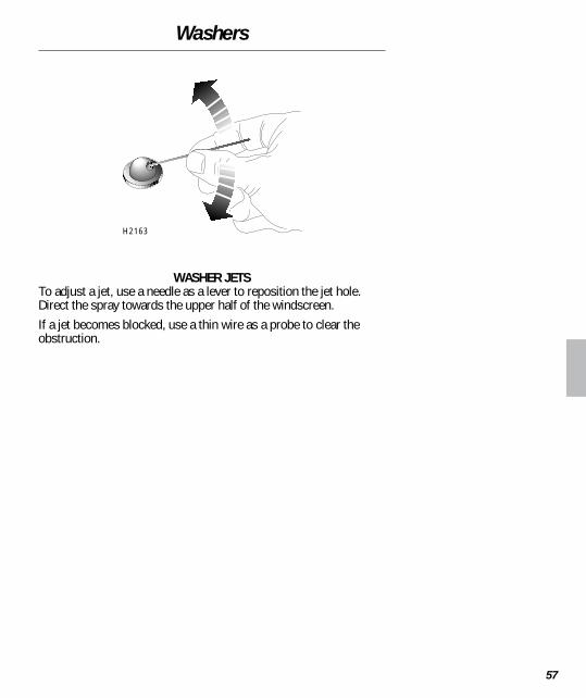
WASHER JETSTo adjust a jet, use a needle as a lever to reposition the jet hole.Direct the spray towards the upper half of the windscreen.If a jet becomes blocked, use a thin wire as a probe to clear theobstruction.
H2163

Wipers
58
WIPER BLADE REPLACEMENT1. Lift the wiper away from the windscreen2. With the blade at right angles to the arm, press the locking tab
(arrowed in LH illustration).3. Keeping the locking tab pressed, slide the wiper blade down the
arm until it is clear of the arm’s hooked end. The blade can thenbe removed.
Fitting replacement blades is a reversal of this process. Only fitreplacement blades that match the original specification.
Care Points .........Grease, silicone and petrolbased products impair theblade’s wiping capability.
• Wash wipers in warm,soapy, water only!
• Protect blades by cleaningwindscreen with glasscleaner after using washand wax products.
If wipers leave streaks orunwiped areas on the screen,replace the blades.
H2125

Battery
59
Battery removal & replacementThe battery is located in the luggage compartment. Beforedisconnecting the battery, remove the starter key and switch off allelectrical equipment.1. Release the securing strap and remove the battery cover.2. Disconnect the battery leads. Always disconnect the negative (-)
terminal before the positive (+) terminal. When reconnecting,connect the positive terminal first.
3. Slacken the nuts securing the battery clamp (arrowed inillustration). Swing the clamp away from the battery, andremove the battery.
Only fit a replacement battery of the same type, size andspecification as the original. Other batteries may not fit the batterycompartment in the luggage floor, or may have different terminalpositions, which could create a fire hazard if the terminals or batteryleads were to come into contact with the battery clamp.
Care Points .........Used batteries are potentiallydangerous; dispose atauthorised waste sites only.After battery disconnection, thehandset may need to bere-synchronised (see ’Handsetbattery’).
After battery disconnection, theradio display may show ’CODE’.Enter the radio security code torestore operation (see ’In-carEntertainment’ book).
WARNING!
For safety, remove metalwrist bands and jewellery.DO NOT allow tools ormetal parts of the car tomake contact with thebattery terminals.
H2115

Battery
60
Battery maintenanceThe battery is a low-maintenance type, and during normal use intemperate climates, will not require topping-up.If it is necessary to top-up the electrolyte, proceed as follows:1. Remove the battery from the car and stand it on a level surface.2. Unscrew the vent caps and add distilled water to each cell,
raising the level of the electrolyte until it is approximately 25mm above the minimum level marked on the side of the battery.
Care Points .........On older batteries, preventcorrosion of the battery leadclamps by liberally smearingthe battery terminals withpetroleum jelly (e.g. Vaseline).
See ’Care Points’ andWARNING! on previous page.
H2114

Battery
61
Battery chargingBefore charging, the battery must be removed from the car and theelectrolyte topped-up above the minimum level (see previouspages).Batteries generate explosive gases, contain corrosive acids andproduce levels of electric current high enough to cause seriousburns. Always observe the following precautions:
• Disconnect the battery charger from the power supply beforeattaching the charger leads to the battery.
• Make sure the leads are securely clamped to the batteryterminals before switching on the charger. DO NOT move theclamps once the charger is switched on.
• Shield your eyes and avoid leaning over the battery.• Ensure the area around the top of the battery is well ventilated.• DO NOT permit naked lights near the battery (inflammable
hydrogen is emitted during and after charging).• When charging has finished, switch off the charger BEFORE
disconnecting the leads to the battery. Leave the battery for anhour before reconnection to the car.
WARNING!
Batteries contain acid. Ifacid contacts the eyes orskin, wash immediatelywith cold water and seekmedical advice.Batteries emit sufficienthydrogen to cause severeexplosions if ignited. Keepnaked lights and sparksaway from the luggagecompartment.

Tyres
62
Tyre careAlways drive with consideration for the condition of the tyres, andfrequently inspect the tread and side walls for punctures and signsof damage. The most common causes of tyre failure are:• Bumping against kerbs.• Driving over kerbs and deep pot holes.• Driving on unmetalled roads.• Driving with over or under-inflated tyres.
Tyre pressuresIncorrectly inflated tyres will wear rapidly, or unevenly, and mayalso seriously affect the car’s stability, road handling and fueleconomy. Check the pressures every week (including the spare),WHEN TYRES ARE COLD.The recommended pressures for COLD TYRES are shown in the’Technical data’ section at the back of this book. If the tyres arewarm, DO NOT let air out in order to match them.
Tyre wear indicatorsWear indicators are moulded into the tread pattern at several pointsaround the circumference of the tyre. As the tread wears, theindicators appear to rise towards the surface. When the depth oftread has reduced to approximately 1.6 mm, the indicators reachthe surface, appearing as a continuous band of rubber, eitheraround the circumference or across the width of the tyre. Thiswarns that there is insufficient depth of tread to provide goodtraction.In the interests of safety, a tyre should be renewed before the wearindicators reach the surface of the tread pattern.
WARNING!
DEFECTIVE OR INCORRECTTYRES ARE DANGEROUS!Do not drive if any tyre isdamaged, excessivelyworn, or inflated to anincorrect pressure.
Only fit tyres that areidentical to the originalspecification or areapproved by Rover.
Operating Tip ..........Be aware that air pressureincreases in warm tyres, andafter as little as a mile ofdriving, the tyres may alreadyhave warmed up and causedthe pressures to have increasedby as much as 6 lbf/in
2(0.4 bar)
- even in cold weather!

Tyres
63
Punctured tyresYour car is fitted with tubeless tyres, which will not normally loseair immediately a sharp object penetrates the casing (provided theobject remains in the tyre!). However, if you are aware that a tyre ispunctured, drive at a reduced speed and with caution until the sparewheel can be fitted. Always have punctured tyres permanentlyrepaired or replaced as soon as possible.
Replacing tyresWheel rims and tyres are matched to suit the handlingcharacteristics of the car. Changing their specification mayadversely affect your safety.Only fit replacement wheels or tyres that conform to thespecification shown in ’Technical Data’ (at the back of this book), orhave been approved by a Rover dealer.
Care Points .........Keep the valve caps screweddown firmly to prevent dirtfrom entering the valve.Frequently inspect the treadand side walls of the tyres forsigns of distortion (bulges),cuts and wear, as well aspunctures to the casing.

Cleaning & Car Care
64
WASHING YOUR CARIf the car is particularly dirty, use a hose to flush grime and gritfrom the surface prior to washing. Then wash the car using a clean,grit-free sponge and cold or lukewarm water containing a goodquality wash and wax shampoo. Always use plenty of water toensure that grit is flushed from the surface and not ground into thepaintwork. After washing, rinse the car with clean water and dry offwith a chamois leather.During the winter if salt has been used on the roads, use a hose towash the underside, paying particular attention to wheelarches andpanel seams.
Removing tar spotsUse white spirit to remove tar spots and stubborn grease stains.Then wash immediately with soapy water to remove all traces of thespirit.
WARNING!
Some high pressurecleaning systems willpenetrate door, window andsunroof seals, and damagelock mechanisms. DO NOTaim water jets directly atcomponents that mighteasily be damaged.
Care Points .........• DO NOT use hot water to
wash the car.
• DO NOT use detergents orwashing up liquid.
• In hot weather, DO NOTwash the car in directsunlight.
• If using a hose, DO NOTdirect the water directly atwindow, door or sunroofseals, or through wheelapertures onto brakecomponents.
• If using an automatic carwash, remove the radioaerial before entering thecar wash.
H2122A

Cleaning & Car Care
65
Protecting paint damageAfter washing, examine the paintwork for damage. Treat paint chipsand scratches with a Rover paint touch-up pencil. If the damage hasrevealed bare metal, use a coloured primer first, then apply the basecoat and finish off with a lacquer pencil, if appropriate. Carry outthis treatment after washing but before polishing or waxing.More extensive damage to paint or bodywork must be repaired inaccordance with the manufacturer’s recommendations - failure todo this may invalidate the Anti-Corrosion Warranty! Ask your Roverdealer for advice.
PolishingOccasionally treat the paint surface with an approved polishcontaining the following properties: - very mild abrasives to removesurface contamination without removing or damaging the paint. -filling compounds that will fill scratches and reduce their visibility. -wax to provide a protective coating between the paint and theelements.Always apply polish with a soft, clean cloth and follow themanufacturers application instructions implicitly.
Windows and mirrorsRegularly clean all windows inside and out using an approved glasscleaner.Windscreen: In particular, clean the outside of the screen with glasscleaner after washing the car with wash and wax products, andbefore fitting new wiper blades.Rear window: Clean the inside with a soft cloth, using a side to sidemotion to avoid damaging the heating elements. DO NOT scrape theglass or use abrasive cleaners - this will damage the heatingelements.Mirrors: Wash with soapy water. Use a plastic scraper to removeice. DO NOT use abrasive cleaners or metal scrapers.
ChromeDo not use any abrasive cleaners, the surface of the chrome will beimpaired.
Care Points .........• If possible, avoid applying
polish or wax products towindow glass or rubberseals.
• DO NOT scrape or useabrasive cleaners on theinside of the rear window -this will damage the heatingelements.
• DO NOT use car polishcontaining coarse abrasives- these will remove thepaint film and damage thegloss finish.

Cleaning & Car Care
66
Wiper bladesWash in warm soapy water. DO NOT use spirit or petrol basedcleaners.
Fabric sun roofWash with soapy water and a sponge, using a brush to removestubborn dirt if necessary. If using a hose, avoid directing the waterjet directly at the seal between sun roof and roof panel. NEVER useabrasive cleaners, or spirit, petroleum and chemical based cleaningagents.Occasionally open the roof and clean dirt and debris from the roofframe. Also, treat the sealing rubber with an approved rubberpreservative, and sparingly lubricate the sliding parts with anacid-free grease, such as Vaseline.
NOTE: In time, the application of too much grease may cause theroof to stick and damage the roof mechanism.

Cleaning & Car Care
67
Body drainage pointsIn muddy conditions, the door and body drainage points (shown inillustration) could become blocked. From time to time use a probe(preferably made from wood or plastic - not metal) to clear anybuild up of debris that might obstruct drainage.
H2126A

Cleaning & Car Care
68
CLEANING THE INTERIORPlastic materials: Clean with diluted upholstery cleaner or warmwater and a non-detergent soap (to achieve a matt, sheen-free,finish).Fabrics: Clean with upholstery cleaner.Leather: Seats and any other trim features should be cleaned withwarm water and a non-detergent soap. Dry and polish the leatherwith a clean, dry, lint-free cloth.Carpet: Clean with diluted upholstery cleaner.
Steering wheel centre pad (airbag module)To prevent damage to the airbag SRS, the steering wheel centre padshould ONLY be cleaned sparingly with a damp cloth andupholstery cleaner. DO NOT flood the area, or use petrol, detergent,furniture cream or other polishes.
Seat beltsExtend the belts, then use warm water and a non-detergent soap toclean. Allow the belts to dry naturally; DO NOT retract them or usethe car until they are completely dry.
FasciaClean with a damp cloth. Use a mild detergent to remove anymarks. A light application of furniture polish will protect the surface.
Care Points .........• DO NOT polish plastic
fascia components - theseshould remainnon-reflective.
• DO NOT use bleaches, dyesor cleaning solvents on seatbelts.

Emergency Towing
69
Towing for recoveryIf your car is to be towed, most qualified recovery specialists willuse wheel lift equipment to suspend the front wheels. However, if itis necessary for the car to be towed with all four wheels on theground, use the front towing eye, located beneath the front bumperand follow this procedure.Before towing:1. Turn the starter key to position ’I’ to unlock the steering and
then to position ’II’ to enable the brake lights, wipers anddirection indicators to be operated if necessary.
2. Place the gear lever in neutral.3. Release the handbrake.
For Your Safety .........While towing do not exceed 30mph (45 km/h) and alwaysremember; without the enginerunning, greater effort will berequired to operate the brakepedal and longer stoppingdistances will be experienced.If, due to an accident orelectrical fault, it is consideredunsafe to turn the starterswitch to position ’I’,disconnect the battery beforeturning the switch.
WARNING!
DO NOT remove the starterkey or turn the starterswitch to position ’0’ whilethe car is in motion.
Care Points .........If a fault with the gearbox issuspected, or theengine/gearbox oil is low, thecar should only be moved onsuspended tow (with the frontwheels raised from theground).
H2209

Emergency Towing
70
Transporter or trailer lashingIf your car should require transporting on the back of a trailer ortransporter, only use the front towing eye and the recommendedlashing points on either side of the rear subframe, illustrated above- DO NOT secure lashing hooks or trailer fixings to other parts ofthe car.When lashing the rear subframe, ensure that any ropes, hooks orfixings pass UNDER the suspension strut.
For Your Safety .........• DO NOT use the lashing
points for towing anothervehicle, trailer or caravan.
H2183A

Wheel Changing
71
CHANGING A WHEELBefore changing a wheel, apply the handbrake and select 1st gear. Ifjacking on a slope, place chocks at the front and rear of the wheeldiagonally opposite the one to be removed.The steel spare wheel and tool kit are stowed in the luggagecompartment.
Positioning the jackPosition the car so that the jack will bear on firm level ground;NEVER on soft ground, or over metal gratings and manhole covers.With the door open, insert the jack head into the jacking point in thesill (see illustration). Turn the jack screw clockwise until the base ofthe jack sits firmly on the ground; check that the jack is vertical withits head fully inserted into the jacking point.
For Your Safety .........• If possible, change the
wheel away from the mainthoroughfare.
• Ensure passengers get outof the car and wait in a safearea away from othertraffic.
• Use your hazard warninglights to alert other roadusers.
WARNING!
NEVER jack the car withpassengers inside.NEVER work beneath thecar with the jack as the onlymeans of support. The jackis designed for wheelchanging only.
H2131

Wheel Changing
72
Changing the wheelIMPORTANT: If the wider 175/50 tyres are fitted to the car, refer tothe important information below before changing the wheel.Before raising the car, slacken the wheel nuts half a turn. Then,using the wheel nut spanner to turn the jack screw, raise the caruntil the tyre is clear of the ground.Remove the wheel nuts and wheel (see ’Locking wheel nuts’).Fit the steel spare wheel and refit the wheel nuts (tapered sidetowards the wheel), tightening them until the wheel is firmly seatedagainst the hub. Do not apply full tightening forces while the tyre isclear of the ground. Lower the car and remove the jack and wheelchocks, then FULLY tighten the wheel nuts in diagonal sequence tothe correct torque (see ’Wheels & tyres’ in ’Technical Data’).
IMPORTANT INFORMATIONFor cars fitted with 175/50 tyres only.The steel spare wheel supplied with these cars is of a differentsize and specification to the (much larger) alloy road wheels, andis for temporary use only. It must be replaced by the normal sizewheel as soon as possible.Use of this wheel is subject to the following:1. If the spare wheel is to be used as a rear wheel: ENSURE thewheel spacer is left in place on the rear hub when the sparewheel is fitted.2. If the spare wheel is to be used as a front wheel: DO NOT3. RESTRICT road speed to a maximum of 50 mph (80 km/h).4. ENSURE the spare tyre is inflated to 28 lbf/in
2(2.0 bar).
accelerate rapidly with the spare wheel fitted.5. Only one spare wheel is to be used on the car at any one time.
For Your Safety .........After changing a wheel, havethe tyre pressure and wheel nuttorque checked as soon aspossible.
Care Points .........Avoid placing wheels facedown on the ground. This mayscratch the alloy surface.

Wheel Changing
73
LOCKING WHEEL NUTSOne locking wheel nut is fitted to each road wheel. Locking wheelnuts are visually similar to standard wheel nuts, but can only beremoved using the special tools provided, as follows:Push the extractor (1) firmly over the head of the locking wheel nut.Pull to remove the nut cover (2).Fit the key socket (3) over the locking wheel nut (4) then, using thewheel nut spanner, unscrew the nut in the normal way.NOTE: The key socket can be retained inside the extractor tubewhen not in use.
IMPORTANT
A code number is stamped onthe face of the socket. Ensurethe number is recorded on theSecurity Information Cardsupplied with the literaturepack. Quote this number ifreplacements are required.For security reasons, DO NOTkeep the card in the car.
34
12
H2124A

Fuses
74
MAIN FUSE BOX - Checking or renewing a fuse1. Turn off the starter switch and all electrical equipment.2. Remove the fuse box cover (use a coin to turn the retaining
screw a quarter turn to left or right), then refer to the chart toidentify the suspect fuse.
3. Hold the head of the fuse and pull to remove. A blown fuse canbe recognised by a break in the wire (see illustration on thefollowing page).
4. Replace a blown fuse with another of the same, or lower, rating.Note that there are a number of spare fuses around theperimeter of the fuse box.
If a replacement fuse fails almost immediately, refer the problem toyour dealer.
In brief ..........Fuses are simple circuitbreakers, which protect thecar’s electrical equipment bypreventing the electrical circuitsfrom being overloaded.A blown fuse may be indicatedwhen the item of electricalequipment it protects stopsworking.
For Your Safety .........Turn off the starter switch andall electrical equipment beforechanging a fuse.Only replace a fuse with one ofthe same, or lower, rating.
Fuse colours:RED 10 ampBLUE 15 ampYELLOW 20 amp
C B A123456789
H2165A

Fuses
75
MAIN FUSE BOX (inside the car)
Fuse No Rating(amps)
Circuits protected
A1 10 Headlight main beam - RHA2 10 Headlight dipped beam - RHA3 10 Side and tail lights - RHA4 10 Alarm system, instruments,
engine managementA5 - -A6 - -A7 - -A8 15 Heater blowerA9 - -
B1 15 Driving lightsB2 10 Rear fog guard lightB3 10 Headlight levellingB4 10 Ignition auxiliaries, radioB5 10 Airbag SRSB6 20 Alarm system and hornB7 15 SunroofB8 15 WipersB9 15 Engine cooling fan
C1 10 Headlight main beam - LHC2 10 Headlight dipped beam - LHC3 10 Side and tail lights - LHC4 10 Radio, brake test switch, alarm,
direction indicators, clockC6 15 Direction indicators, stop lights,
reversing lightsC7 10 Fuel pumpC8 10 Engine crankingC9 15 Heated rear screen
A blown fuse can be recognisedby a break in the wire.
H2161

Fuses
76
ENGINE COMPARTMENT FUSESFour fusible links are situated in a small fuse box at the front righthand side of the engine compartment. These protect the wiringbetween the battery and the main fuse box, and should be checkedif an electrical failure appears to have affected a number of differentsystems, or one which has not caused a fuse to fail in the main fusebox.
H2167

Fuses
77
A single 15 amp fuse, located on the right side of the enginecompartment protects the front fog lights (if fitted).
H2168

Bulb Replacement
78
Headlight (and sidelight)1. Remove the screw and headlight finisher.2. Using a screwdriver as a lever (see illustration), lever the
headlight to the left (looking towards the front of the car), andspring it free of the retaining screw (arrowed in illustration). Theheadlight can then be lifted clear of the other two retainingscrews. Note that all three retaining
For Your Safety .........Check the operation of allexterior lights before you usethe car.
Care Points .........Before replacing a bulb, turn offthe lighting switch to avoid anypossibility of a short circuit.Only replace bulbs with thesame type and specification.
During use, headlight bulbsmay shatter if the glass hasbeen scratched, orcontaminated with oil orperspiration. DO NOT touch theglass. If handled, clean withmethylated spirits and a cleancloth.
H2169
4
1
3
6
2
5

Bulb Replacement
79
screws also control headlight alignment and, for this reason,must not be removed; they are mounted in a pliable materialwith sufficient flexibility to enable the headlight to be sprungfree without disturbing the alignment.
3. Detach the plug from the back of the headlight, and pull backthe rubber boot.
4. Sidelight: Pull the bulb holder from the back of the headlight.Push and twist the bulb to remove.
5. Headlight: Unhook both ends of the retaining clip, then removethe bulb. When replacing, ensure that the larger of the threerectangular tabs on the bulb’s base plate fits the uppermost sloton the rear of the light unit.
6. When replacing the headlight unit, ensure the slots in theheadlight rim engage between the shoulder and head of theretaining screws (see inset).
Front direction indicator1. Remove two screws securing the lens to the body.2. Hold the lens firmly and twist the bulb holder a quarter turn
anti-clockwise to release it from the lens.3. Push and twist the bulb anti-clockwise to remove it from the
bulb holder.
H2135

Bulb Replacement
80
Fog and driving lights (if fitted)1. Remove the screw at the base of the light. This will release the
lens and bulb assembly from the lamp body.2. Detach both electrical connectors.3. Unhook both sides of the retaining clip, and pivot the clip away
from the rear of the light.4. The bulb can now be removed. When replacing a bulb, note that
shaped cut-outs in the metal base plate ensure the bulb’scorrect alignment.
Care Points .........During use, these bulbs mayshatter if the glass has beenscratched, or contaminatedwith oil or perspiration. DONOT touch the glass. Ifhandled, clean with methylatedspirits and a clean cloth.
1
3 42
H2138
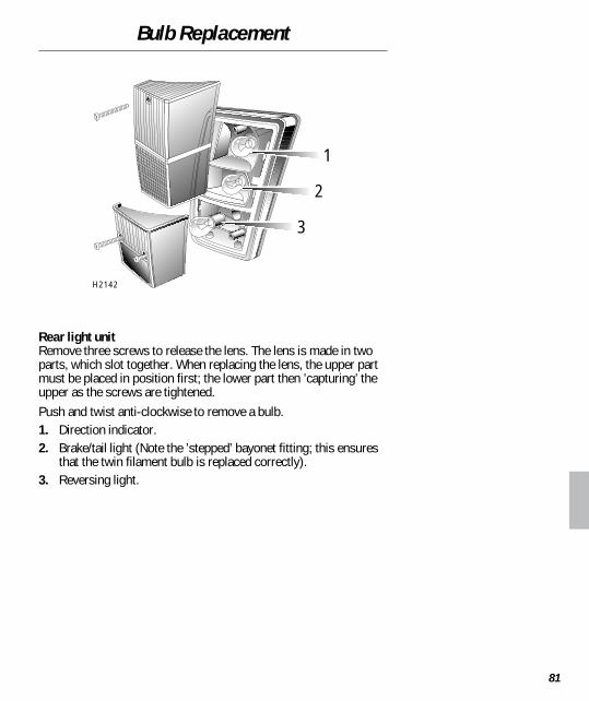
Bulb Replacement
81
Rear light unitRemove three screws to release the lens. The lens is made in twoparts, which slot together. When replacing the lens, the upper partmust be placed in position first; the lower part then ’capturing’ theupper as the screws are tightened.Push and twist anti-clockwise to remove a bulb.1. Direction indicator.2. Brake/tail light (Note the ’stepped’ bayonet fitting; this ensures
that the twin filament bulb is replaced correctly).3. Reversing light.
1
2
3
H2142

Bulb Replacement
82
Rear fog guard lightRemove two screws securing the lens to the body. Remove thelens, then push and twist the bulb anti-clockwise to remove it fromthe holder.
Number plate lightRemove two screws securing the lens to the light housing. Ease thelight unit from its recess and pull the bulb to remove.
H2140
H2132

Bulb Replacement
83
Side repeater light1. Push the light unit firmly to the right to withdraw it from the
front wing.2. Twist the bulb holder anti-clockwise to release it from the lens.3. Pull to remove the bulb from its socket.
Interior lightFrom the end opposite the switch, use a small, flat-bladed, screwdriver to prise the light unit from the roof lining.Push and twist the bulb anti-clockwise to remove it from the bulbholder.
H2134
H2113

Bulb Replacement
84
REPLACEMENT BULBSHeadlight (halogen): 60/55 watts GLB 472Auxiliary (halogen): 55 watts GLB 453Sidelight: 4 watts GLB 233Direction indicator: 21 watts GLB 382Side repeater: 5 watts GLB 501Reversing light: 21 watts GLB 382Stop/tail light: 21/5 watts GLB 380Fog guard light: 21 watts GLB 382Number plate light: 5 watts GLB 239Interior light: 10 watts GLB 245

Parts & Accessories
85
SERVICE PARTS & ACCESSORIESOnly Rover dealers are able to provide the full range ofrecommended parts and accessories that meet our rigorousstandards of safety, durability and performance.It makes sense, therefore, to always consult a Rover dealerregarding the suitability, installation and use of any parts andaccessories.
Travelling abroadIn some countries it may be illegal to fit parts that have not beenmade to the vehicle manufacturer’s specification. Owners shouldensure that any parts or accessories fitted to the car while travellingabroad will also conform to the legal requirements of their homecountry.
WARNING!
Fitting parts or accessoriesthat have not beenapproved by Rover may bedangerous and couldinvalidate the vehiclewarranty.If an airbag SRS is fitted,ALWAYS consult a Roverdealer before fitting anyspare part or accessory.
It may be dangerous to fitparts or accessories whereinstallation requires thedismantling of, or additionto, either the electrical orfuel systems.
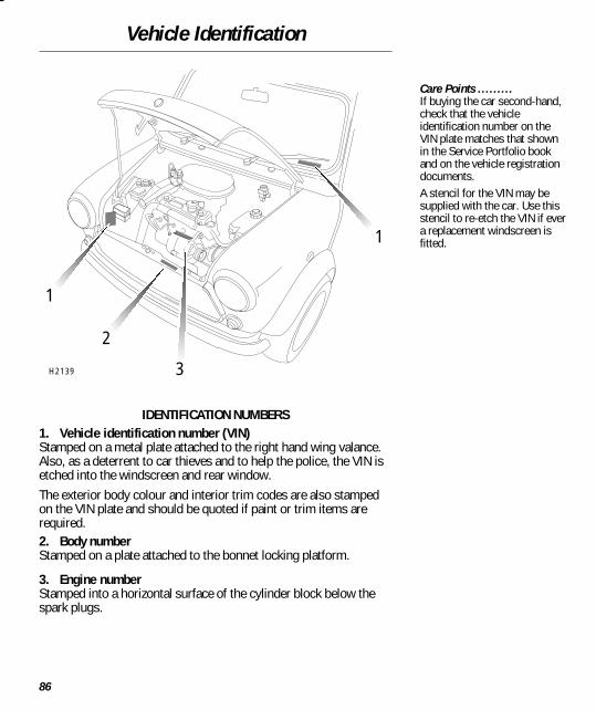
Vehicle Identification
86
IDENTIFICATION NUMBERS1. Vehicle identification number (VIN)Stamped on a metal plate attached to the right hand wing valance.Also, as a deterrent to car thieves and to help the police, the VIN isetched into the windscreen and rear window.The exterior body colour and interior trim codes are also stampedon the VIN plate and should be quoted if paint or trim items arerequired.2. Body numberStamped on a plate attached to the bonnet locking platform.
3. Engine numberStamped into a horizontal surface of the cylinder block below thespark plugs.
Care Points .........If buying the car second-hand,check that the vehicleidentification number on theVIN plate matches that shownin the Service Portfolio bookand on the vehicle registrationdocuments.A stencil for the VIN may besupplied with the car. Use thisstencil to re-etch the VIN if evera replacement windscreen isfitted.1
1
2
3H2139

Technical Data
87
Engine
Capacity 1275 cm3
................................................................Firing order 1-3-4-2............................................................Idle speed 875 rev/min..............................................................Fuel 95 RON UNLEADED to EN 228 specification........................................................................
Ignition system
Type Programmed ignition system......................................................................Spark plugs NGK BPR6E..........................................................Spark plug gap 0.85 ± 0.05 mm......................................................
Electrical
Battery type Low maintenance..........................................................Voltage/polarity 12V, negative (-) earth....................................................
Wheels & tyres
Wheel size & type:Alloy wheel (standard) 4.5 x 12......................................Alloy wheel (option) 6 x 13..........................................Steel spare wheel 4.5 x 12..............................................
Road wheel nut torque 60 Nm..........................................
Tyre size:Standard 145/70 SR12..........................................................Option 175/50 VR13 Dunlop SP Sport 2000 or..............................................................
3000Spare (steel wheel) 145/70 SR12............................................
Tyre pressures:145/70 SR12 (Standard) 28 lbf/in
2.................................. 2.0 bar..........................
175/50 VR13 (Option)Front 28 lbf/in
2.............................................................. 2.0 bar..........................
Rear 26 lbf/in2
.............................................................. 1.8 bar..........................Spare (145/70 SR12 steel wheel) 28 lbf/in
2...................... 2.0 bar..........................

Technical Data
88
Weights
Approx unladen weight (full fuel tank,excluding options) 715 kg................................................ 1576 lb..............................Maximum gross vehicle weight 1050 kg............................ 2315 lb............................Maximum rear axle weight 510 kg.................................... 1124 lb..............................Maximum roof rack load* 50 kg.................................... 110 lb................................
* The maximum roof rack load is conditional on the vehicle loading being restricted to threeoccupants and no boot luggage (see ’Load carrying’).
Dimensions
Overall length 3.05 m........................................................ 10 ft 0.25 in..............................Overall width (including door mirrors) 1.58 m.................. 5 ft 2.2 in..............................Overall height (at unladen weight) 1.34 m........................ 4 ft 5 in..............................Wheelbase 2.04 m............................................................ 6 ft 8 in..............................Turning circle (kerb to kerb):
145/70 tyres 8.6 m.................................................. 28ft 2.5 in................................175/50 tyres 8.8 m.................................................. 28ft 10.5 in................................
Capacities
Engine oil (refill) 4.8 litre.................................................... 8.4 pt............................Fuel tank 34 litre................................................................ 7.5 gal..............................Cooling system 4.0 litre...................................................... 7 pt............................Washer reservoir 2.3 litre.................................................. 4.0 pt............................
H2128

Technical Data
89
FUEL CONSUMPTION
The fuel consumption figures shown below have been calculated using a standard testingprocedure (the new EC test procedure from Directive 93/116/EC), and produced inaccordance with The Passenger Car Fuel Consumption (Amendment) Order 1996. Undernormal use, a car’s actual fuel consumption figures may differ from those achieved throughthe test procedure, depending on driving technique, road and traffic conditions,environmental factors, vehicle load and condition.
Fuel consumption figures
URBAN EXTRA-URBAN COMBINEDmpg mpg mpgl/100km l/100km l/100km
33.4 51.8 43.08.5 5.5 6.6
Urban cycleThe urban test cycle is carried out from a cold start and consists of a series of accelerations,decelerations and periods of steady speed driving and engine idling. The maximum speedattained during the test is 31 mph (50 km/h) with an average speed of 12 mph (19 km/h).
Extra-urban cycleThe extra urban test cycle is carried out immediately after the urban test. Approximately halfof the test comprises steady-speed driving, while the remainder consists of a series ofaccelerations, decelerations and engine idling. The maximum test speed is 75 mph (120km/h) and the average speed 39 mph (63 km/h). The test is carried out over a distance of 4.3miles (7 km).
CombinedThe combined figure is an average of the urban and extra-urban test cycle results, which hasbeen weighted to take account of the different distances covered during the two tests.
NOTE: These figures should not be compared with figures produced using the ECE/EECprocedure previously required by The Passenger Car Fuel Consumption Order 1983. Becauseof the changes in test procedure, even the urban figures would differ if the same car weresubjected to both tests.

Index
90
AAccessories 85Aerial 28Airbag SRS 15, 32Alarm system 4Anti-freeze 53Anti-theft alarm 4Anti-theft alarm indicator 32Ashtray 27
BBattery 59Battery charging 32Body number 86Bonnet opening 50Brake fluid level 55Brake pads 46Braking system 46, 54Bulb replacement 78
CCapacities 88Car care 64Catalytic converter 37Child seats 13Cleaning 64Clock 26Clutch fluid level 54Controls 3Cooling system 53
DData 86Demister (rear screen) 45Dimensions 88Dipstick - engine oil 52Direction indicators 33, 43
Distance recorder 30Door locks 5Driving lamps 43
EEmpty fuel tank 40Engine 52Engine compartment 51Engine immobilisation 4Engine number 86Engine oil 52Engne 87
FFace level vents 23Fog guard lights (rear) 45Fog lights 45Fuel consumption 89Fuel cut-off switch 41Fuel economy 36Fuel filler 40Fuel gauge 30Fuel system 40Fuses 74
GGearbox 39General data 86Glovebox 27
HHandbrake 47Handset 8Handset battery 9Hazard warning lights 45Head restraints 10Headlight levelling 44
Headlights 33, 43Heating 23
IIdentification numbers 86Ignition system 87In-car entertainment 28Indicators 43Instruments 30Interior light 25Interior mirror 18
JJacking 71
KKeys 5
LLights 43Load carrying 29Locking wheel nuts 73Locks 4Luggage compartment lock 6
MMaintenance 48Mirrors 18
NNumber plate light 82
OOil level (engine) 52Owner maintenance 48

Index
91
PParking 35Parts 85Poisonous fluids 49Polishing 65Pre-tensioners 14Punctured tyres 63
RRadio 28Radio aerial 28Radio/cassette player 28Rear fog guard light 45Rear screen demister 45Rear window shelf 29Roof rack 29Running-in 36
SSafety in the garage 49Seat belt safety 12Seat belts 12Seats 10Security information card 8Service Portfolio book 48Side repeater light 83Sidelights 43Snow chains 63Spare wheel 71Speedometer 30Starter switch 34Starting 34Steering lock 34Sun visor 19Sunroof 21Switches 45Switching off 35
TTachometer 30Technical data 86Temperature gauge 30Towing 69Towing for recovery 69Tyre pressures 62, 87Tyres 62, 87
VVanity mirror 19Vehicle identification number
(VIN) 86Ventilation 23
WWarning lights 32Washer jets 57Washing your car 64Weights 88Wheel changing 71Wheels 87Windows 20Windscreen washers 42, 56Wiper blade replacement 58Wipers 42, 58
Emergency Procedures
Bulb replacement 78Fuel cut-off switch 41Fuses 74Hazard warning lights 45Sunroof emergency operation 22Towing for recovery 69Wheel changing 71