mini oontz: 3d printed midi controller - adafruit · pdf filemini oontz: 3d printed midi...
TRANSCRIPT

Mini OONTZ: 3D Printed MIDI ControllerCreated by Noe Ruiz
Last updated on 2014-08-03 10:30:12 PM EDT

2445677888
101113131414151516171718181920202122222225
Guide Contents
Guide ContentsOverview
DIY MIDI ControllerAdafruit TrellisPrerequisite GuidesPartsTools & Supplies
3D Printing3D Printed Mini OONTZ EnclosureCustomize SolidsSlicer Settings
Circuit DiagramWire ConnectionsInstall Trellis Library to Arduino
Prep ComponentsInsert 3mm LEDs to TrellisSolder LEDs to TrellisTrim Trellis LEDsMale Jumper WiresTin Trellis PCBSolder Wires to Trellis PCBFile Trellis Edges10k PotentiometersRemove 'stubs' from PotsAdd Pots to Enclosure CoverSecure Cover with PotsWire common ground and 5V on PotsSolder Jumper Wires to PotsConnect Trellis to LeonardoTest TrellisConfirm LEDs are working on Trellis
© Adafruit Industries https://learn.adafruit.com/mini-oontz-3d-printed-midi-controller Page 2 of 45

26272727272728282932323333343435363637373839394040414242434445
TrellisTest SketchSoftware
Install OONTZ + Trellis Arduino LibrariesInstall Teensyduino to Mod Arduino IDEUploading Sketches to Leonardo MIDIMIDI LoopMIDI Note MappingPotentiometers MIDI CCMINI OONTZ Sketch
AssemblyAdd Tray to Enclosure frameInstall Tray to Enclosure frameInstall Trellis PCB to TraySecure Trellis to TrayInstall Elastomers to Trellis PCBInsert Pot Wires into EnclosureAdd Cover to Enclosure FrameSecure Cover to Enclosure FrameSecured Enclosure and CoverAdd Leonardo to BottomMount Arduino Leonardo to BottomConnect Trellis+Pot jumper wires to Arduino LeonardoLine up Bottom with EnclosureSecure Bottom to Enclosure FramePotentiometer KnobsLittle Rubber Bumper Feet
Configure MIDIMIDI OSX SetupMini OONTZ Device IconUsing with iOS DevicesControlling Analog MIDI Synths
© Adafruit Industries https://learn.adafruit.com/mini-oontz-3d-printed-midi-controller Page 3 of 45
Overview
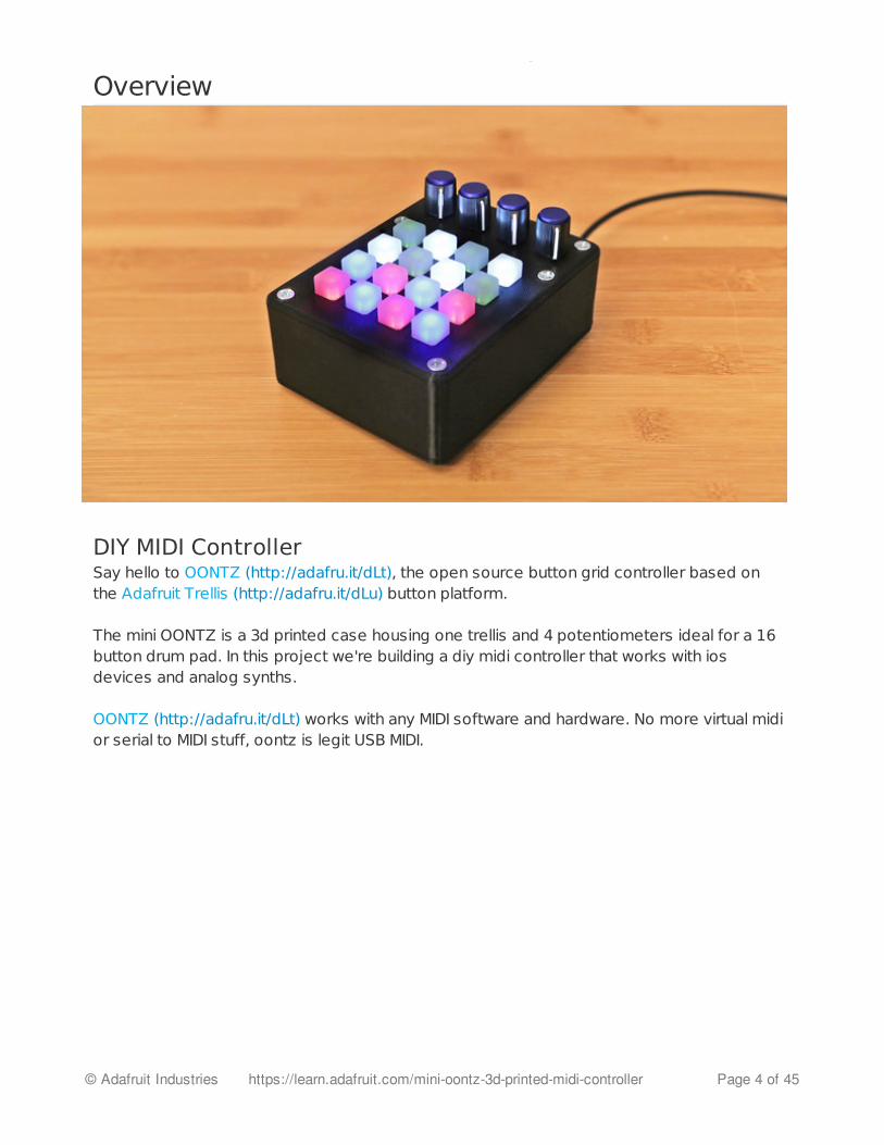
DIY MIDI ControllerSay hello to OONTZ (http://adafru.it/dLt), the open source button grid controller based onthe Adafruit Trellis (http://adafru.it/dLu) button platform.
The mini OONTZ is a 3d printed case housing one trellis and 4 potentiometers ideal for a 16button drum pad. In this project we're building a diy midi controller that works with iosdevices and analog synths.
OONTZ (http://adafru.it/dLt) works with any MIDI software and hardware. No more virtual midior serial to MIDI stuff, oontz is legit USB MIDI.
© Adafruit Industries https://learn.adafruit.com/mini-oontz-3d-printed-midi-controller Page 4 of 45

Adafruit TrellisThis PCB is specially made to match the Adafruit 4x4 elastomerkeypad (http://adafru.it/1611). Each Trellis PCB (http://adafru.it/dLv) has 4x4 pads and 4x4matching spots for 3mm LEDs (http://adafru.it/778). The circuitry on-board handles thebackground key-presses and LED lighting for the 4x4 tile. However, it does not have anymicrocontroller or other 'brains' - an Arduino (or similar microcontroller) is required to controlthe Trellis to read the keypress data and let it know when to light up LEDs as desired.
© Adafruit Industries https://learn.adafruit.com/mini-oontz-3d-printed-midi-controller Page 5 of 45

Prerequisite GuidesBefore starting this project, we recommend doing a walk-through of the following guides toget you familiar with the hardware, and soldering (if your new to the craft!).
OONTZ: a Trellis MIDI Instrument (http://adafru.it/dLw)Introducing Adafruit Trellis (http://adafru.it/dxx)Adafruit Guide to Excellent Soldering (http://adafru.it/drI)
© Adafruit Industries https://learn.adafruit.com/mini-oontz-3d-printed-midi-controller Page 6 of 45

PartsWe have all the parts in the shop for building this project. The potentiometer knobs can be3D Printed (http://adafru.it/dLx) or get some nice ones on the internets.
1 4x4 Adafruit Trellis Monochrome Driver (http://adafru.it/1616)1 Silicone Elastomer 4x4 button keypad (http://adafru.it/dLy)1 Arduino Leonardo (http://adafru.it/dy8)4 10k Potentiometers (http://adafru.it/dzq)
Tools & SuppliesThe following tools and supplies will get you started on your build.
3D Printer (http://adafru.it/doT)Soldering Iron (http://adafru.it/dLz)16x 3mm LEDs (http://adafru.it/dLA)Flush diagonal cutters (http://adafru.it/diI)Premium Male Jumper Wires (http://adafru.it/759)14 #6-32 1/2' Flat Phillip Screws
© Adafruit Industries https://learn.adafruit.com/mini-oontz-3d-printed-midi-controller Page 7 of 45
3D Printing
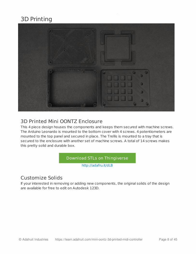
3D Printed Mini OONTZ EnclosureThis 4 piece design houses the components and keeps them secured with machine screws.The Arduino Leonardo is mounted to the bottom cover with 4 screws. 4 potentiometers aremounted to the top panel and secured in place. The Trellis is mounted to a tray that issecured to the enclosure with another set of machine screws. A total of 14 screws makesthis pretty solid and durable box.
Download STLs on Thingiverse
http://adafru.it/dLB
Customize SolidsIf your interested in removing or adding new components, the original solids of the designare available for free to edit on Autodesk 123D.
© Adafruit Industries https://learn.adafruit.com/mini-oontz-3d-printed-midi-controller Page 8 of 45

Download Solids on AutoDesk123D
http://adafru.it/dLC
© Adafruit Industries https://learn.adafruit.com/mini-oontz-3d-printed-midi-controller Page 9 of 45

Slicer SettingsWe recommend using the slice settings below. For really great quality prints, we recommendusing PLA over ABS.
mini-oontz-cover.stlmini-oontz-tray.stlmini-oontz-frame.stlmini-oontz-bottom.stl
PLA@2402 Shells10% Infill90/120 Speeds0.2 Layer height
© Adafruit Industries https://learn.adafruit.com/mini-oontz-3d-printed-midi-controller Page 10 of 45

Circuit Diagram
© Adafruit Industries https://learn.adafruit.com/mini-oontz-3d-printed-midi-controller Page 11 of 45

© Adafruit Industries https://learn.adafruit.com/mini-oontz-3d-printed-midi-controller Page 12 of 45

Wire ConnectionsFollow the circuit diagram above to reference the wires are connected. You will need tosolder wires to the Trellis PCB and 4 potentiometers. Use male jumper on the Trellis wires toeasily connect to the headers on the Leonardo.
The Trellis PCB will have 4 wires, SDA, SCL, GND and 5V that will connect the SDA, SCL,GND and 5V pins on the Arduino Leonardo.
The 4 pots have common ground and 5V power in series. The middle terminals connectthe the A0-A3 pins on the Arduino Leonardo.
Install Trellis Library to ArduinoIn order to control the trellis with the Arduino Leonardo, you will need to install the TrellisArduino Library. Download Arduino IDE (http://adafru.it/d8v). Download the zipfile (http://adafru.it/cZg) below. Add the folder to ~/Documents/Arduino/libraries/.Extract it and rename the folder to Adafruit_Trellis. Restart the Arduino IDE. Goto File >Examples and check to see if Adafruit_Trellis is listed. If it is, move on to the next page!
Adafruit Trell is Library
http://adafru.it/cZg
© Adafruit Industries https://learn.adafruit.com/mini-oontz-3d-printed-midi-controller Page 13 of 45

Prep Components
Insert 3mm LEDs to TrellisSecure the Trellis PCB to a panavise jr. or third helping hand. With the top of the facing up,insert the 3mm LED into the Trellis PCB with the longer leg going into the +positive pin.Bend the legs apart to secure the LED in place.
Make sure to triple check the polarity of the LEDs!
© Adafruit Industries https://learn.adafruit.com/mini-oontz-3d-printed-midi-controller Page 14 of 45

Solder LEDs to TrellisFlip the Trellis over with the back side facing up. The LEDs should be secured in place. If not,make sure they are! Solder the 16 LEDs to the Trellis PCB.
Trim Trellis LEDs
© Adafruit Industries https://learn.adafruit.com/mini-oontz-3d-printed-midi-controller Page 15 of 45

Use flush diagonal cutters to trim the excess terminals of the LEDs.
Male Jumper WiresGrab 4 different colored male jumper wires and remove the plastic part from the one end ofall 4 jumper wires. Trim off half of the exposed terminal, leaving just a small portion.
© Adafruit Industries https://learn.adafruit.com/mini-oontz-3d-printed-midi-controller Page 16 of 45
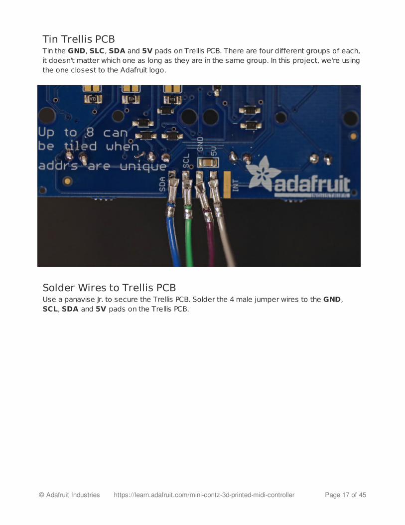
Tin Trellis PCBTin the GND, SLC, SDA and 5V pads on Trellis PCB. There are four different groups of each,it doesn't matter which one as long as they are in the same group. In this project, we're usingthe one closest to the Adafruit logo.
Solder Wires to Trellis PCBUse a panavise Jr. to secure the Trellis PCB. Solder the 4 male jumper wires to the GND,SCL, SDA and 5V pads on the Trellis PCB.
© Adafruit Industries https://learn.adafruit.com/mini-oontz-3d-printed-midi-controller Page 17 of 45

File Trellis EdgesIn order to fit the Trellis into the tray, you will need to file down the edges to remove thisexcess material. There's two small parts on each side.
10k Potentiometers
© Adafruit Industries https://learn.adafruit.com/mini-oontz-3d-printed-midi-controller Page 18 of 45

Bend the three terminals on each of the 10k potentiometers like in the photo.
Remove 'stubs' from PotsA small metal 'stub' on top of the base prevents the potentiometer from being flush with thecover. Remove this metal tip by bending it off with flat pliers.
© Adafruit Industries https://learn.adafruit.com/mini-oontz-3d-printed-midi-controller Page 19 of 45

Add Pots to Enclosure CoverInstall the four potentiometers to the mini-oontz-cover.stl part with the knob facing theprinted surface of the cover. They should pop into place. If the tolerance are too tight, usean x-acto knife or dremel to open up the mounting holes.
Secure Cover with PotsYou'll need to wire up the 4 pots so they share common ground and 5V. Use a panavise jr.to secure the mini-oontz-cover.stl part that has the 4 pots installed.
© Adafruit Industries https://learn.adafruit.com/mini-oontz-3d-printed-midi-controller Page 20 of 45

Wire common ground and 5V on PotsUse 22AWG solid core wire to connect the common ground and 5V on the 4 pots together inseries. Use a third-helping hand to secure the 22 gauge wire close to the pot terminal leadsand solder in place.
© Adafruit Industries https://learn.adafruit.com/mini-oontz-3d-printed-midi-controller Page 21 of 45

Solder Jumper Wires to PotsSolder one jumper wire to each of the middle terminals of the 4 potentiometers. This makesit easier to arrange and connect the wires.
Connect Trellis to LeonardoHook up the jumper wires on the trellis to the headers on the Leonardo to make thefollowing connections:
SCL to SCLSDA to SDAGND to GND5V to 5V
Test TrellisWith the Trellis connect to the Leonardo, you can now upload a test sketch to check thepolarity of the LEDs are all good. Copy + Paste the code below into a new sketch. SelectTools > Board > Arduino Leonardo in the top menu. Ensure programmer is set toUSBTinyISP. Plug a USB micro cable into the Leonardo and connect it to the USB port ofyour computer, then hit the upload arrow button.
Install Trellis Arduino Library before uploading code.
© Adafruit Industries https://learn.adafruit.com/mini-oontz-3d-printed-midi-controller Page 22 of 45

/***************************************************
This is a test example for the Adafruit Trellis w/HT16K33
Designed specifically to work with the Adafruit Trellis
----> https://www.adafruit.com/products/1616
----> https://www.adafruit.com/products/1611
These displays use I2C to communicate, 2 pins are required to
interface
Adafruit invests time and resources providing this open source code,
please support Adafruit and open-source hardware by purchasing
products from Adafruit!
Written by Limor Fried/Ladyada for Adafruit Industries.
MIT license, all text above must be included in any redistribution
****************************************************/
#include <Wire.h>
#include "Adafruit_Trellis.h"
/***************************************************
This example shows reading buttons and setting/clearing buttons in a loop
"momentary" mode has the LED light up only when a button is pressed
"latching" mode lets you turn the LED on/off when pressed
Up to 8 matrices can be used but this example will show 4 or 1
****************************************************/
#define MOMENTARY 0
#define LATCHING 1
// set the mode here
#define MODE LATCHING
Adafruit_Trellis matrix0 = Adafruit_Trellis();
// uncomment the below to add 3 more matrices
/*
Adafruit_Trellis matrix1 = Adafruit_Trellis();
Adafruit_Trellis matrix2 = Adafruit_Trellis();
Adafruit_Trellis matrix3 = Adafruit_Trellis();
// you can add another 4, up to 8
*/
// Just one
Adafruit_TrellisSet trellis = Adafruit_TrellisSet(&matrix0);
// or use the below to select 4, up to 8 can be passed in
© Adafruit Industries https://learn.adafruit.com/mini-oontz-3d-printed-midi-controller Page 23 of 45

// or use the below to select 4, up to 8 can be passed in
//Adafruit_TrellisSet trellis = Adafruit_TrellisSet(&matrix0, &matrix1, &matrix2, &matrix3);
// set to however many you're working with here, up to 8
#define NUMTRELLIS 1
#define numKeys (NUMTRELLIS * 16)
// Connect Trellis Vin to 5V and Ground to ground.
// Connect the INT wire to pin #A2 (can change later!)
#define INTPIN A2
// Connect I2C SDA pin to your Arduino SDA line
// Connect I2C SCL pin to your Arduino SCL line
// All Trellises share the SDA, SCL and INT pin!
// Even 8 tiles use only 3 wires max
void setup() {
Serial.begin(9600);
Serial.println("Trellis Demo");
// INT pin requires a pullup
pinMode(INTPIN, INPUT);
digitalWrite(INTPIN, HIGH);
// begin() with the addresses of each panel in order
// I find it easiest if the addresses are in order
trellis.begin(0x70); // only one
// trellis.begin(0x70, 0x71, 0x72, 0x73); // or four!
// light up all the LEDs in order
for (uint8_t i=0; i<numKeys; i++) {
trellis.setLED(i);
trellis.writeDisplay();
delay(50);
}
// then turn them off
for (uint8_t i=0; i<numKeys; i++) {
trellis.clrLED(i);
trellis.writeDisplay();
delay(50);
}
}
void loop() {
delay(30); // 30ms delay is required, dont remove me!
© Adafruit Industries https://learn.adafruit.com/mini-oontz-3d-printed-midi-controller Page 24 of 45

Confirm LEDs are working on Trellis
if (MODE == MOMENTARY) {
// If a button was just pressed or released...
if (trellis.readSwitches()) {
// go through every button
for (uint8_t i=0; i<numKeys; i++) {
// if it was pressed, turn it on
if (trellis.justPressed(i)) {
Serial.print("v"); Serial.println(i);
trellis.setLED(i);
}
// if it was released, turn it off
if (trellis.justReleased(i)) {
Serial.print("̂ "); Serial.println(i);
trellis.clrLED(i);
}
}
// tell the trellis to set the LEDs we requested
trellis.writeDisplay();
}
}
if (MODE == LATCHING) {
// If a button was just pressed or released...
if (trellis.readSwitches()) {
// go through every button
for (uint8_t i=0; i<numKeys; i++) {
// if it was pressed...
if (trellis.justPressed(i)) {
Serial.print("v"); Serial.println(i);
// Alternate the LED
if (trellis.isLED(i))
trellis.clrLED(i);
else
trellis.setLED(i);
}
}
// tell the trellis to set the LEDs we requested
trellis.writeDisplay();
}
}
}
© Adafruit Industries https://learn.adafruit.com/mini-oontz-3d-printed-midi-controller Page 25 of 45

TrellisTest SketchIf everything is correct (trellis arduino libraries installed in the right place, polarity of LEDs,etc), you should see a short animation sequence of the LED's lighting up. As the commentsnote: This example shows reading buttons and setting/clearing buttons in a loop"momentary" mode has the LED light up only when a button is pressed "latching" mode letsyou turn the LED on/off when pressed.
© Adafruit Industries https://learn.adafruit.com/mini-oontz-3d-printed-midi-controller Page 26 of 45

Software
Install OONTZ + Trellis Arduino LibrariesFollow the guide on how to setup the arduino IDE with the special OONTZ libraries that willallow you to program the Leonardo to perform like a native USB MIDI device.
Install Arduino Libraries
http://adafru.it/dz5
Install Teensyduino to Mod Arduino IDEYou will need to install the Tennsyduino for your operating system. It's a special damon thatupdates your install of the Arduino IDE to have that special menu for uploading MIDI code tothe Leonardo. Click the link below to get instructions on installing Teensyduino.
Install Teensyduino for Arduino
http://adafru.it/dy3
Uploading Sketches to Leonardo MIDIIn certain cases, once the Arduino Leonardo has the MIDI uploaded, it won't be able toupload new code until the reset button is pressed. Keep this in mind when attemptingto upload new sketches.
MIDI LoopThe code below uses the usbMIDI.sendNoteOn and usbMIDI.sendNoteOff calls foreach button to change the state of the MIDI note. The note[i] variable is set in the table. 127is the velocity of the midi note, being the highest/hardest. Channel is a reference that isdefined in the top of the sketch.
Ensure the TeeOnArdu + OONTZ library are installed!
for(uint8_t i=0; i<16; i++) { // For each button...
if(trellis.justPressed(i)) {
usbMIDI.sendNoteOn(note[i], 127, CHANNEL);
trellis.setLED(i);
} else if(trellis.justReleased(i)) {
usbMIDI.sendNoteOff(note[i], 0, CHANNEL);
trellis.clrLED(i);
}
© Adafruit Industries https://learn.adafruit.com/mini-oontz-3d-printed-midi-controller Page 27 of 45

MIDI Note MappingThis table lists the midi notes that are mapped the 16 buttons on the Trellis. The values areordered just like the 4x4 grid on the Trellis. "60" is equal to C3, while "48" will trigger note C2.The full range of notes in this table are visually represented below. This map syncs perfectlywith the TRG-16 performance pad in NanoStudio (http://adafru.it/dLD). For a list of the flurange of available notes, check out this page (http://adafru.it/dLE).
Potentiometers MIDI CCThe 4 potentiometers are mapped to MIDI CC 1, 11, 12 and 13. The blocks of code belowuse the usbMIDI.sendControlChange call to define which potentiometer will be mappedto a MIDI CC. The analogRead(#) call refers to the analog input on the Arduino Leonardo.
pot = map(ArdiunoPin(#)), 0(lowest MIDI value), 1023(highest MIDI value);usbMIDI.sencControlChange(Arduino Pin, pot, CHANNEL);
}
}
uint8_t note[] = {
60, 61, 62, 63,
56, 57, 58, 59,
52, 53, 54, 55,
48, 49, 50, 51
};
mod = map(analogRead(0), 0, 1023, 0, 127);
vel = map(analogRead(1), 0, 1023, 0, 127);
fxc = map(analogRead(2), 0, 1023, 0, 127);
rate = map(analogRead(3),0, 1023, 0, 127);
usbMIDI.sendControlChange(1, mod, CHANNEL);
usbMIDI.sendControlChange(11, vel, CHANNEL);
usbMIDI.sendControlChange(12, fxc, CHANNEL);
usbMIDI.sendControlChange(13, rate, CHANNEL);
© Adafruit Industries https://learn.adafruit.com/mini-oontz-3d-printed-midi-controller Page 28 of 45

MINI OONTZ SketchCopy and paste the full code below into a new sketch. The 16 buttons on the Trellis aremapped to trigger LEDs+MIDI notes. 4 potentiometers are mapped to MIDI CCs.
uint8_t newModulation = map(analogRead(0), 0, 1023, 0, 127);
if(mod != newModulation) {
mod = newModulation;
usbMIDI.sendControlChange(1, mod, CHANNEL);
}
#include <Wire.h>
#include <Adafruit_Trellis.h>
#define LED 13 // Pin for heartbeat LED (shows code is working)
#define CHANNEL 1 // MIDI channel number
Adafruit_Trellis trellis;
uint8_t heart = 0; // Heartbeat LED counter
unsigned long prevReadTime = 0L; // Keypad polling timer
uint8_t mod;
uint8_t vel;
uint8_t fxc;
uint8_t rate;
uint8_t note[] = {
60, 61, 62, 63,
56, 57, 58, 59,
52, 53, 54, 55,
48, 49, 50, 51
};
void setup() {
pinMode(LED, OUTPUT);
trellis.begin(0x70); // Pass I2C address
#ifdef __AVR__
// Default Arduino I2C speed is 100 KHz, but the HT16K33 supports
// 400 KHz. We can force this for faster read & refresh, but may
// break compatibility with other I2C devices...so be prepared to
// comment this out, or save & restore value as needed.
TWBR = 12;
#endif
trellis.clear();
trellis.writeDisplay();
mod = map(analogRead(0), 0, 1023, 0, 127);
© Adafruit Industries https://learn.adafruit.com/mini-oontz-3d-printed-midi-controller Page 29 of 45

mod = map(analogRead(0), 0, 1023, 0, 127);
vel = map(analogRead(1), 0, 1023, 0, 127);
fxc = map(analogRead(2), 0, 1023, 0, 127);
rate = map(analogRead(3),0, 1023, 0, 127);
usbMIDI.sendControlChange(1, mod, CHANNEL);
usbMIDI.sendControlChange(11, vel, CHANNEL);
usbMIDI.sendControlChange(12, fxc, CHANNEL);
usbMIDI.sendControlChange(13, rate, CHANNEL);
}
void loop() {
unsigned long t = millis();
if((t - prevReadTime) >= 20L) { // 20ms = min Trellis poll time
if(trellis.readSwitches()) { // Button state change?
for(uint8_t i=0; i<16; i++) { // For each button...
if(trellis.justPressed(i)) {
usbMIDI.sendNoteOn(note[i], 127, CHANNEL);
trellis.setLED(i);
} else if(trellis.justReleased(i)) {
usbMIDI.sendNoteOff(note[i], 0, CHANNEL);
trellis.clrLED(i);
}
}
trellis.writeDisplay();
}
uint8_t newModulation = map(analogRead(0), 0, 1023, 0, 127);
if(mod != newModulation) {
mod = newModulation;
usbMIDI.sendControlChange(1, mod, CHANNEL);
}
uint8_t newVelocity = map(analogRead(1), 0, 1023, 0, 127);
if(vel != newVelocity) {
vel = newVelocity;
usbMIDI.sendControlChange(11, vel, CHANNEL);
}
uint8_t newEffect = map(analogRead(2), 0, 1023, 0, 127);
if(fxc != newEffect) {
fxc = newEffect;
usbMIDI.sendControlChange(12, fxc, CHANNEL);
}
uint8_t newRate = map(analogRead(3), 0, 1023, 0, 127);
if(rate !=newRate) {
rate = newRate;
usbMIDI.sendControlChange(13, rate, CHANNEL);
}
© Adafruit Industries https://learn.adafruit.com/mini-oontz-3d-printed-midi-controller Page 30 of 45

prevReadTime = t;
digitalWrite(LED, ++heart & 32); // Blink = alive
}
while(usbMIDI.read()); // Discard incoming MIDI messages
}
© Adafruit Industries https://learn.adafruit.com/mini-oontz-3d-printed-midi-controller Page 31 of 45

Assembly
Add Tray to Enclosure framePosition the tray over the frame and orient it so that the mounting holes are lined upprecisely. You'll notice two sets of holes are positioned slightly different.
© Adafruit Industries https://learn.adafruit.com/mini-oontz-3d-printed-midi-controller Page 32 of 45

Install Tray to Enclosure frameInsert the mini-oontz-tray.stl part into the mini-oontz-frame.stl with one end sliding infirst. Make sure to line up the holes.
Install Trellis PCB to TrayPosition and rotate the Trellis so that the numbers are upright with the opening for thepotentiometers. Group the jumper cables from the trellis and pull them through one of theopening of the tray.
© Adafruit Industries https://learn.adafruit.com/mini-oontz-3d-printed-midi-controller Page 33 of 45

Secure Trellis to TrayPlace the Trellis down into the tray and snap it into place.
Install Elastomers to Trellis PCBGrab the 4x4 silicone elastomers and position them over the Trellis PCB. Orient the keypad
© Adafruit Industries https://learn.adafruit.com/mini-oontz-3d-printed-midi-controller Page 34 of 45
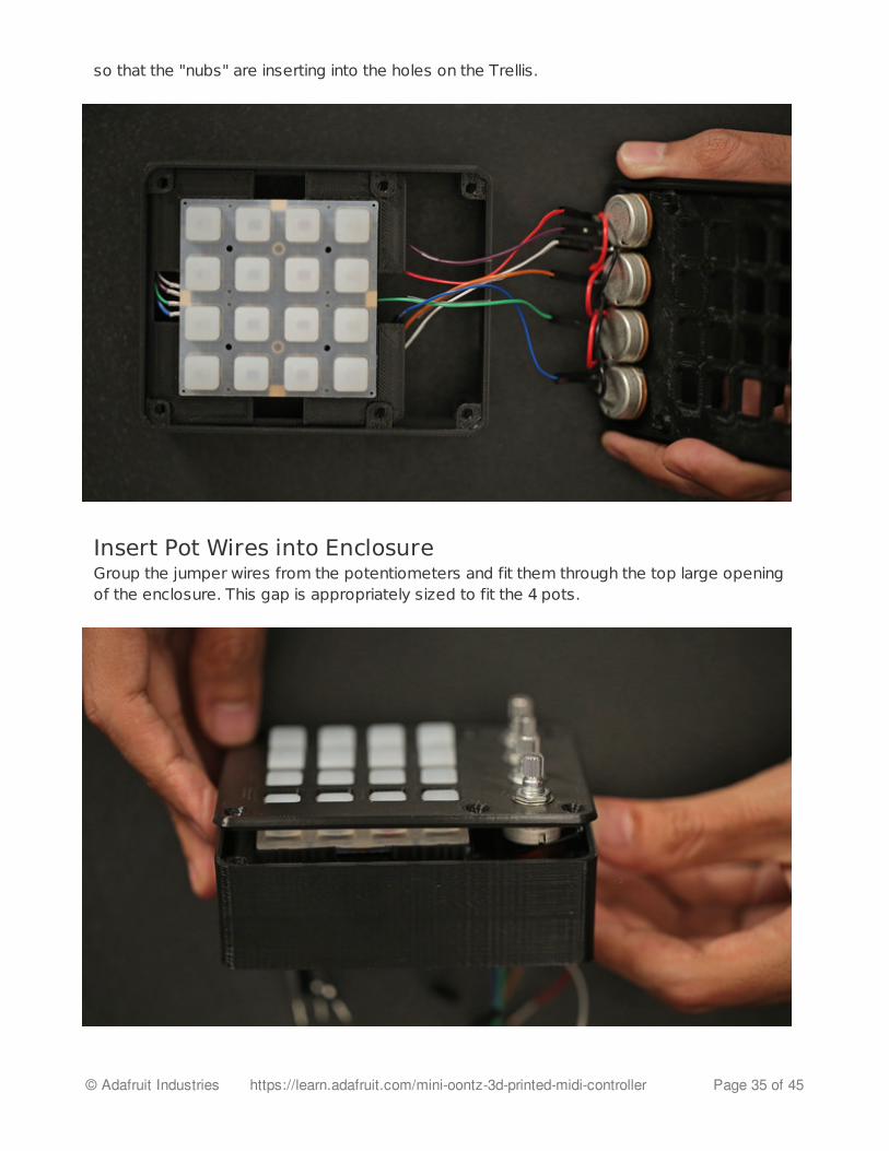
so that the "nubs" are inserting into the holes on the Trellis.
Insert Pot Wires into EnclosureGroup the jumper wires from the potentiometers and fit them through the top large openingof the enclosure. This gap is appropriately sized to fit the 4 pots.
© Adafruit Industries https://learn.adafruit.com/mini-oontz-3d-printed-midi-controller Page 35 of 45

Add Cover to Enclosure FramePosition the mini-oontz-cover.stl over the mini-oontz-frame.stl with the mount holes lined up.
Secure Cover to Enclosure FramePlace the cover down onto the frame and snap it shut. Use 6 #6-32 1/2' flat phillips screwsto secure the cover to the frame.
© Adafruit Industries https://learn.adafruit.com/mini-oontz-3d-printed-midi-controller Page 36 of 45

Secured Enclosure and CoverYey! The 6 screws keep the Trellis PCB and 4 potentiometers secured inside the enclosure.
Add Leonardo to BottomPlace the Leonardo over the mini-oontz-bottom.stl part and make sure the mount holes
© Adafruit Industries https://learn.adafruit.com/mini-oontz-3d-printed-midi-controller Page 37 of 45

line up.
Mount Arduino Leonardo to BottomUse 4 #6-32 x 1/2' to secure the Leonardo board to the bottom cover.
© Adafruit Industries https://learn.adafruit.com/mini-oontz-3d-printed-midi-controller Page 38 of 45
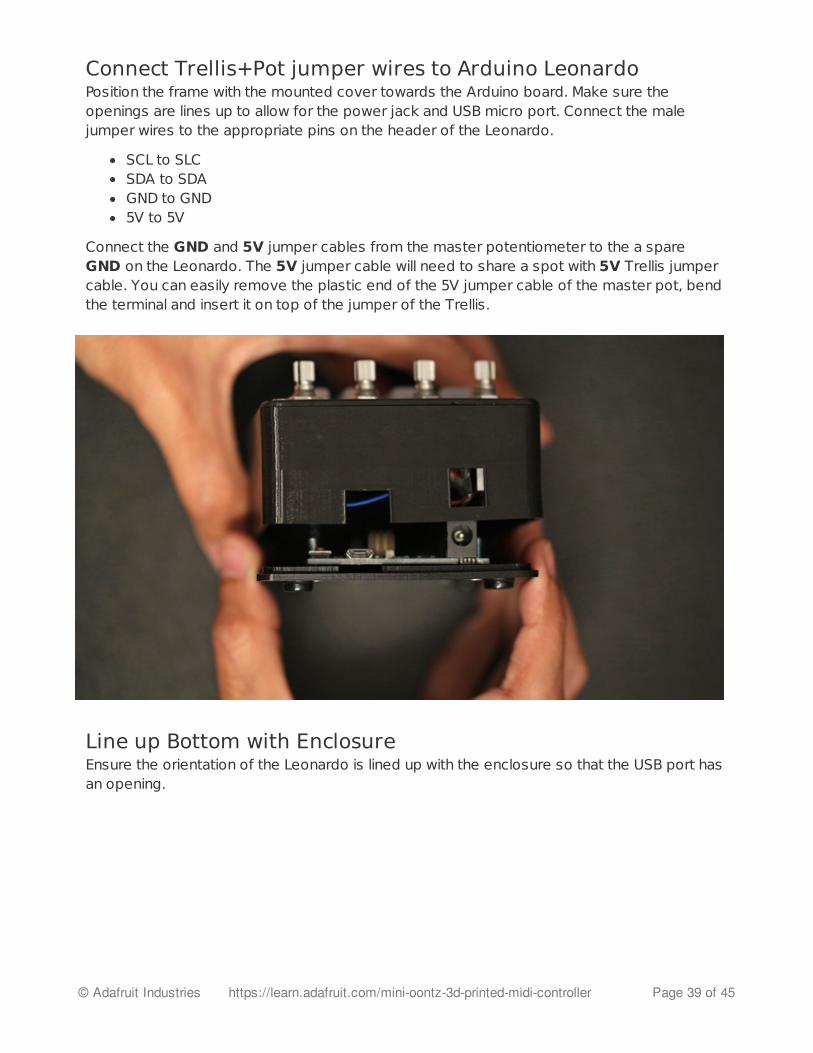
Connect Trellis+Pot jumper wires to Arduino LeonardoPosition the frame with the mounted cover towards the Arduino board. Make sure theopenings are lines up to allow for the power jack and USB micro port. Connect the malejumper wires to the appropriate pins on the header of the Leonardo.
SCL to SLCSDA to SDAGND to GND5V to 5V
Connect the GND and 5V jumper cables from the master potentiometer to the a spareGND on the Leonardo. The 5V jumper cable will need to share a spot with 5V Trellis jumpercable. You can easily remove the plastic end of the 5V jumper cable of the master pot, bendthe terminal and insert it on top of the jumper of the Trellis.
Line up Bottom with EnclosureEnsure the orientation of the Leonardo is lined up with the enclosure so that the USB port hasan opening.
© Adafruit Industries https://learn.adafruit.com/mini-oontz-3d-printed-midi-controller Page 39 of 45
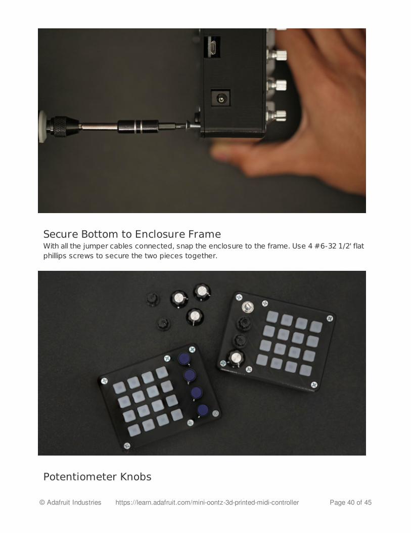
Secure Bottom to Enclosure FrameWith all the jumper cables connected, snap the enclosure to the frame. Use 4 #6-32 1/2' flatphillips screws to secure the two pieces together.
Potentiometer Knobs
© Adafruit Industries https://learn.adafruit.com/mini-oontz-3d-printed-midi-controller Page 40 of 45

You can 3D print your own knobs or get some neat ones on the internets. I picked up 1/2'pot knobs from RadioShack (http://adafru.it/dLF).
Little Rubber Bumper FeetKeep your mini OONTZ from going barefoot, give them little rubberfeet (http://adafru.it/dLG)! These small sticky bumpers are our favorite accessory for anyelectronic kit or device. They are sticky, but not impossible to remove.
© Adafruit Industries https://learn.adafruit.com/mini-oontz-3d-printed-midi-controller Page 41 of 45

Configure MIDI
MIDI OSX SetupTo configure your OONTZ, you can launch the Audio MIDI Setup app by searching for it inFinder. It usually likes to reside in the ~/HD/Applications/Utilities directory. Oncelaunched, go to the top menu and select Window > Show MIDI Window.
You should see the TeeOnArdu MIDI object listed in the MIDI studio window. Double click it tosee MIDI Ports and rename, change icon/color, etc if you'd like.
© Adafruit Industries https://learn.adafruit.com/mini-oontz-3d-printed-midi-controller Page 42 of 45
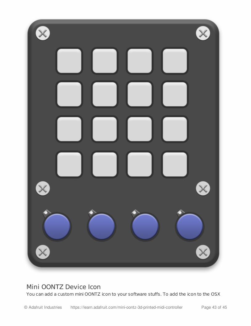
Mini OONTZ Device IconYou can add a custom mini OONTZ icon to your software stuffs. To add the icon to the OSX
© Adafruit Industries https://learn.adafruit.com/mini-oontz-3d-printed-midi-controller Page 43 of 45

You can add a custom mini OONTZ icon to your software stuffs. To add the icon to the OSXMidi window, simply drop the PNG icon to the following directory. You'll need to enter yourpassword to set the proper permission. ~/HD/Library/Audio/MIDIDevices/Generic/Images
Using with iOS DevicesThe USB Camera Kit adapter (http://adafru.it/dLH) allows you to use the OONTZ with any MIDIenabled iOS App. Just plug it in, a wait second and discard the dialog pop up. You may needto enable omni mode in your iOS app in order for OONTZ to control MIDI.
© Adafruit Industries https://learn.adafruit.com/mini-oontz-3d-printed-midi-controller Page 44 of 45

Controlling Analog MIDI SynthsAnalog MIDI synths that use MIDI cables can be controlled with the OONTZ using a MIDI toUSB interface. Using an old school MIDI cable, you can connect the midi input of your analogsynth to the output of the Midi to USB interface. Once configured and connect, OONTZ willact like any other USB classic MIDI device.
© Adafruit Industries Last Updated: 2014-08-03 10:30:14 PM EDT Page 45 of 45