mini metertm in flush mount enclosure with …mini metertm in flush mount enclosure with wireless...
TRANSCRIPT

Mini MeterTM in Flush Mount Enclosure with Wireless AMR Option
Installation ManualCat No. 6P201, 6W201
DI-000-A3246-00A WE
B V
ER
SIO
N

WE
B V
ER
SIO
N

TABLE OF CONTENTS
1 Warnings and Cautions
2 Product Description
2.1 General Description
2.2 Meter Features
2.3 Meter Certifications
2.4 Model Numbers
2.5 Physical Description
2.5.1 Mini Meter in Flush Mount Enclosure
2.5.2 Tamper Protection
2.6 Functional Description
3 Technical Specifications
3.1 Electrical Specifications
3.2 Input/Output Connections
4 Installation Instructions
4.1 Preparation
4.2 List of Materials
4.3 Mounting the Enclosure
4.3.1 Mounting Location
4.3.2 Making Conduit Openings 4.4 Installation of Voltage Lines
4.5 Installation of Current Transformers
4.5.1 General Requirements
4.5.2 Installing Solid Core CTS
4.6 Flush Mount Enclosure Installation
4.7 Testing the Installation
5 Wireless Automatic Meter Reading
5.1 MDT Transceiver Wiring
5.2 Network Activation
6 Maintenance
7 Troubleshooting
8 Warranty
9 Contact Information
4
5
5
5
5
5
6
6
6
6
7
7
8
10
10
10
10
10
11
12
13
13
13
14
16
17
17
17
20
21
22
23
WE
B V
ER
SIO
N

1 WARNINGS AND CAUTIONS
The following section contains installation and wiring instructions for the Leviton MiniMeter an indoor flush mount enclosure. If technical assistance is required at any pointduring the installation, contact information can be found at the end of this manual.Leviton is not responsible for damage to the meter caused by incorrect wiring, which will void the product’s warranty.
4
WARNING:
• TO AVOID FIRE, SHOCK OR DEATH; TURN OFF POWER at circuit breaker or fuse and test that the power is off before installing product or servicing current transformers.
• TO AVOID FIRE, SHOCK OR DEATH; Look inside the meter and electrical panel for possible exposed wire, broken wire, damaged components or loose connections.
• Make sure all tools used during installation have proper installation ratings.
• Installations should be done in accordance with local codes and current National Electric Code requirements, and performed by trained, qualified professionals.
• Equipment used in a manner not specified by this document impairs the protection provided by the equipment.
CAUTIONS:
• Verify the model number and electrical specifications of the device being installed to confirm they are appropriate for the intended electrical service (see Section 3).
• Consult local codes for any possible permits or inspections required before beginning electrical work.
• Like repeaters, MDTs should not be mounted inside a metal box or near a metal wall (i.e. heating furnace or electrical panel). Consult the Tehama QuickStart Guide, which can be downloaded from the manufacturers website.
• MDTs must be mounted using velcro, tie-wraps, or screws. Don’t let the MDT dangle by the pulse input wire.
• Avoid locations with dampness, high humidity, or an abundance of mold.
• Ensure the conduit for the installation is flexible and non-metallic. For outdoor applications conduit and conduit fittings must be rated UL Type 4X for outdoor enclosures. Failure to use the appropriate conduit impairs the degree of equipment protection.
WE
B V
ER
SIO
N

2 PRODUCT DESCRIPTION
2.1 General Description
The Leviton Mini Meter is a self-powered, current transformer (CT) rated electronic kilowatt-hour (kWh) meter designed for permanent connection to an electrical service. This guide is for use with the dual element (1PH 120/240V or 2PH 120/208V, 3-Wire) Mini Meter in a flush mount enclosure.
2.2 Meter Features
• Exceeds Revenue-grade accuracy • Built in LCD display
• Multiple load monitoring with a single meter • Isolated Pulse outputs • Tamper Micro Switch • 5-year warranty
2.3 Meter Certifications
• UL Listed Component for use in US or Canada • NRTL certified compliance with ANSI C12.1 and C12.20 (0.5) • Wireless option complies with NY DPS and NYSERDA requirements for
revenue grade submeters
2.4 Model Numbers
5
6P201-C02 Flush Mount Mini MeterTM Kit, LCD Display, Isolated Pulse Outputs
6W201-C02 Flush Mount Mini MeterTM Kit, LCD Display, Isolated Pulse Outputs, TOU enabled kWh Meter Data Transceiver
6W201-D02 Flush Mount Mini MeterTM Kit, LCD Display, Isolated Pulse Outputs, TOU and Temperature enabled kWh Meter Data Transceiver
6W201-E02 Flush Mount Mini MeterTM Kit, LCD Display, Isolated Pulse Outputs, TOU and 1% Delta Temperature enabled kWh Meter Data Transceiver
Table 1 - Mini Meter Kit Models & Options
WE
B V
ER
SIO
N

2 PRODUCT DESCRIPTION
2.5 Physical Description
2.5.1 Mini Meter in Flush Mount Enclosure
2.5.2 Tamper Protection
Two flat-head screws that secure the enclosure front may be covered with adhesive-type security seals that indicate tampering when removed. Also, some models provide a tamper indication through the wireless AMR system when enclosure cover is removed.
2.6 Functional Description The 6P201 versions of the Mini Meter accurately quantifies electrical energy usage
of 1PH 2W or 2PH 3W 120/208V or 120/240V loads. Solid Core Current Transformers are used to measure current flowing to a load. Energy information (pulses) is recorded by the onboard wireless transceiver, which time stamps kWh readings in 15-minute intervals and sends it over a secure wireless network to a Data Concentrating Access Point (DCAP), where data from a network of meters is stored for on a local computer for billing or energy management functions, or data can be pushed from the DCAP or pulled from remote locations via an ethernet connection.
6
9.88 in.
5.67 in. 4.60 in.
1.54 in.
8.81 in.
Figure 1 - Mini Meter flush mount enclosure dimensions
4.620 in.
2.845 in.2.150 in.
3.525 in.
5.130 in.
5.130 in.
1.107 in.1.282 in.
.125 in.
WE
B V
ER
SIO
N

3 TECHNICAL SPECIFICATIONS
7
Table 2 - Electrical and Environmental Specifications
1 Product approved for use with included Leviton Current Transformers, as follows:
• 200A: Part Numbers CDA02-K12 (Black) or CDA02-R12 (Red).2 Pollution Degree 2: normally only non-conductive pollution occurs. Occasionally, however, a
temporary conductivity caused by condensation can happen.
3.1 Electrical and Environmental Specifications
The Mini Meter device falls under UL Circuit Category III: devices for measurements performed in the building installation. The electrical and environmental specifications for Mini Meter devices are given in the table below.
Input Configurations 1 Phase, 2 wire 1 or 2 Phase, 3 wire
Supply Voltage Range (L1 or L2 to Neutral)
Min. 102 VAC Max. 138 VAC
Maximum Input Power 8 VA
Maximum Rated Current1 220 A primary for 200 A models 110 A primary for 100 A models 0.11 A secondary for 0.1 A secondary models 0.22 A secondary for 0.2 A secondary models
Line Frequency 50-60 Hz
Power Factor Range 0.5 to 1.0, leading or lagging
Accuracy +/- 0.5% of registration @ 1.0pf. 2 to 200 A +/- 0.75% of registration @ 0.5pf, 2 to 200 A
Operating Temperature Range -30 to +70 degrees C
Rated Pollution Degree2 2
Rated Relative Humidity 80%
Branch Fuse Holder Klemsan ASK2 or equiv.
250 V, 1 A, fast acting, short time lag
Terminal Blocks Mini Meter Dinkle/International Connector OSTVI110152
4.4 in-lb of torque maximum
WE
B V
ER
SIO
N

3 TECHNICAL SPECIFICATIONS
3.2 Input/Output Connections and User Display
8
Figure 2 - Mini Meter Connections and Display
Table 2A - Input Connections
LCD Display Wireless Data Transceiver
Tamper MicroSwitch
Load LED
L1 X1 X2CT1 CT2 (Kh) Isol
Isolated Output
X1 X2 10 100 1000Counter
+12VDC
1 2COML2N
MDT
Voltage Inputs (wire connections) Description
L1 Black wire, voltage input, Line 1, 120 V with respect to neutral
N White wire, Neutral input
L2 Red wire, voltage input, Line 2, 120 V with respect to neutral (2 phase models only)
CT Inputs
CT1 : X1 Current Transformer input, CT1. Colored wire of CT 1
CT1 : X2 Current Transformer input, CT1. White wire of CT1
CT2 : X1 Current Transformer input, CT2. Colored wire of CT 2. (2 phase models only)
CT2 : X2 Current Transformer input, CT2. White wire of CT2 (2 phase models only)
WE
B V
ER
SIO
N

10, Isolated Output (10 Wh/P, Kh = 10) Isolated pulse output: 5 watthours on, 5 watthours off, referenced to ISOL COM.Connected at factory to wireless transceiver. ISOL COM NOT TO BE USED FOR FIELD WIRING
LED Indicators Description
Load LED (green) 50% duty cycle LED to verify proper meter function when connected to a load. At 200 watts, LED will flash 1.5 minutes on, 1.5 minutes off; with no load, LED will remain on or off
LCD Display LCD display that shows total kWh (also displays kw demand, instantaneous kw, error codes if applicable, and more information upon boot. Refer to the Mini Meter manual for complete information)
3 TECHNICAL SPECIFICATIONS
9
Table 3 - Display Indicators
Table 2B - I/O Connections
3.2 Input/Output Connections and User Display
Outputs Description
100, Isolated Output (100 Wh/P, Kh=100) Isolated pulse output: 50 watthours on, 50 watthours off, referenced to ISOL COM
1000, Isolated Output (1 kWh/P, Kh=1000) Isolated pulse output: 500 watthours on, 500 watthours off, referenced to ISOL COM (not available on models with T suffix)
ISOL COM Isolated common for 10/100/1000 isolated outputs
Counter (kh = 100 or kh = 1000)* For 12 VDC electro-mechanical counter
+12 VDC 12 VDC output; current rating is 3 mA max.
* Recommended Leviton Mechanical Counters part numbers are: MPCTR-1KW (1kWh) and MPCTR-TKW (0.1kWh).
WE
B V
ER
SIO
N

4 INSTALLATION INSTRUCTIONS
4.1 Preparation
WARNINGS
• TO AVOID FIRE, SHOCK OR DEATH; TURN OFF POWER at circuit breaker or fuse and test that power is off before installing product or servicing current transformers.
• TO AVOID FIRE, SHOCK OR DEATH; Look inside the meter and electrical panel for possible exposed wire, broken wire, damaged components or loose connections.
CAUTIONS
• Ensure the conduit for the installation is flexible and non-metallic. For outdoor applications conduit and conduit fittings must be rated UL Type 4X for outdoor enclosures. Failure to use the appropriate conduit impairs the degree of equipment protection.
• Specification for branch circuit protection, rated min. 250 V, 1A, for voltage sense / input leads.
4.2 List of Materials
• Mini Meter, flush mount enclosure and associated mounting materials, two #6 x 15/8 drywall screws.
• Additional wiring for CT or voltage leads extension if needed. Wires must be 18 AWG or thicker and insulated for 300 VAC min.
• Current Transformers (CTs): This product is designed for use with Leviton CTs
• Flexible, non-metallic conduit and fittings; UL Type 4X for outdoor applications.
4.3 Mounting the Enclosure
4.3.1 Mounting Location
• Mini Meter flush mount enclosures require a switch or circuit breaker as part of the building installation.
• The switch or circuit breaker must be marked as the disconnecting device for the Mini Meter.
• It is recommended that the enclosure be mounted near the disconnecting device in an area with adequate ventilation.
• Ensure that the CT and voltage lead lengths (and conduit lengths) are capable of reaching the enclosure from the load center.
• If a suitable mounting location near the load center cannot be found, additional in-line fuses or circuit breaker may be required in accordance with NEC regulations.
10 WE
B V
ER
SIO
N
4 INSTALLATION INSTRUCTIONS
4.3.2 Making Conduit Openings
It is recommended that conduit holes be placed in the lower left compartment of the
flush mount enclosure, just below the Mini Meter I/O terminal block. Conduit hole sizes must be appropriate to fittings, and large enough to fit all voltage and CT wiring (4-7 18 AWG min. wires insulated for 300 V min.).
11 WE
B V
ER
SIO
N

4 INSTALLATION INSTRUCTIONS
4.4 Installation of Voltage Lines
WARNING: TO AVOID FIRE, SHOCK OR DEATH; TURN OFF POWER at circuit breaker or fuse and test that the power is off before wiring! Verify that branch circuit fuse specifications meet local electric codes (see section 3.2).
1. Based on desired mounting location, check if additional in-line fuses are required to meet local electric codes. (See section 4.3.1 for mounting location requirements and recommendations).
2. Mini Meter devices come standard with voltage wires pre-connected to the metering board.
3. Route wires through conduit to the breaker panel.
4. Trim the wire to the appropriate length to avoid coils of excess wiring.
5. Following all national and local electric codes, connect wires to appropriate locations in the load center. Wires should be tightened so that they are held snuggly in place, but do not to over-tighten, as this may compress and weaken the conductor. See figure 5 for Mini Meter wiring diagram.
12 WE
B V
ER
SIO
N
4 INSTALLATION INSTRUCTIONS
4.5 Installation of Current Transformers
WARNING: TO AVOID FIRE, SHOCK OR DEATH; TURN OFF POWER at circuit breaker or fuse and test that the power is off before installing or servicing current transformers.
CAUTION: In accordance with NEC, CTs may not be installed in any panel board where they exceed 75% of the wiring space of any cross-sectional area. Violation
of the electric code could be punish by a fine or imprisonment.
4.5.1 General Requirements
• Field wired CT connections are made to the Mini Meter terminal block. The rated torque for these terminal blocks is 4.4 in-lb, and can be used with solid and stranded copper wires, at 12-18 AWG.
• Splices on the CT leads must be within the meter enclosure, not inside the conduit.
• Leviton-provided CT leads are approximately 48 inches. Wire insulation should be stripped so that the bare conductor length that connects to the meter terminal block does not exceed 0.300 inches.
• CTs should be securely fastened such that they will not slide down to live terminals.
• Wires should be tightened so that they are held snuggly in place, but do not to overtighten, as this may compress and weaken the conductor.
• Current and voltage inputs must be installed ‘in phase’ for accurate readings (e.g. CT1 on Line 1, CT2 on Line 2)
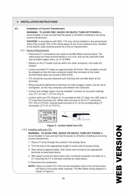
• Leviton solid core CTs (Figure 3): In accordance with CT label, the LINE side of CT must face incoming Line. White lead connects to X2 of CT connection (CT1:X2 or CT2:X2). Colored lead connects to X1 of the corresponding CT connection (CT1:X1 or CT2:X1).
4.5.2 Installing solid core CTs
WARNING: TO AVOID FIRE, SHOCK OR DEATH; TURN OFF POWER at circuit breaker or fuse and test that the power is off before installing or servicing current transformers.
1. Route CT wires through the conduit if not already done.
2. Trim the wire to the appropriate length to avoid coils of excess wiring.
3. Strip wiring to approximately .300 inches and connect to the appropriate terminals as described above.
4. With power turned off, disconnect each monitored conductor and slide on a CT, ensuring the CT is correctly oriented as noted above.
5. Reconnect the conductors.
NOTE: Failure to install CTs in the correct orientation and on the correct phase will lead to inaccurate meter readings. The Mini Meter wiring diagram is shown in Figure 5.
13
Figure 3 - Leviton Solid Core CTs
WE
B V
ER
SIO
N

4 INSTALLATION INSTRUCTIONS
4.6 Flush Mount Enclosure Installation
The Flush Mount Enclosure uses preinstalled clamps (Figure 4). After performing steps 1 and 2 after section 4.5.2, follow the instructions for the appropriate enclosure.
1. Select a desired installation location following the guidelines of 4.3.1.
2. Make a 4.5” x 8.75” hole in the mounting surface for the enclosure to be situated. See Figure 1 for enclosure dimensions.
3. Unscrew the clamps to their maximum distance and orient them parallel with the enclosure as show in frame 2 of Figure 4.
4. Slide the meter into the wall opening and tighten the clamp screws as in frame 3 of Figure 4.
5. After running the tests in Section 4.7, place the cover on the meter and attach with the provided screws.
14
Figure 4 - Flush Mount Enclosure Installation
WE
B V
ER
SIO
N

L1 X1 X2CT1 CT2 (Kh) Isol
Isolated Output
X1 X2 10 100 1000Counter
+12VDC
1 2COML2N
DUAL ELEMENT, MINI METER WIRING DIAGRAM
LINE 1
120 V
NEUTRAL
LOAD
LINE
LINE 2
240 Vor
208 V
CT1H1
CT2
X2
X1
X2
X1
H1
120 V
L1 X1 X2CT1 CT2 (Kh) Isol
Isolated Output
X1 X2 10 100 1000Counter
+12VDC
1 2COML2N
SINGLE ELEMENT, MINI METER WIRING DIAGRAM
LINE 1
120 V
NEUTRAL
LOAD
LINE
CT1H1
X2
X1
Secure clear coverwith two screws after wiring(2 places)
888888
Optional 12VDC Counter(Kubler Type K46 or Equivalent)
Optional 12VDC Counter(Kubler Type K46 or Equivalent)
888888
Manufacturer is not responsible fordamage to the meter caused byincorrect wiring
Secure clear coverwith two screws after wiring(2 places)
4 INSTALLATION INSTRUCTIONS
15
Figure 5: Dual and single element Mini Meter hookup diagram
WE
B V
ER
SIO
N

4 INSTALLATION INSTRUCTIONS
4.7 Testing the Installation
Testing Voltage
The LCD illuminates when the Mini Meter has a proper power supply. Voltage should also be tested using an AC voltmeter to verify that the voltage across voltage line terminals (L1 to Neutral and L2 to Neutral) is not in excess of the maximum rated voltage.
Load LED
The load LED is described in section 3. This LED should be cycling at 50% duty cycle when the meter is connected properly and a sufficient load is applied.
16 WE
B V
ER
SIO
N
5 WIRELESS AUTOMATIC METER READING
17
5.2 Network Activation
For complete wireless system commissioning information, consult the Tehama QuickStart Guide, which can be downloaded from the manufacturers website.
DCAP NOTE: The DCAP should be the first device installed and powered. Once the
DCAP is in place and powered, the Repeater Backbone can then be installed. Repeaters Power up repeaters starting with the closest to the DCAP and progressing out
to the one farthest from the DCAP. This will allow remote Repeaters to see the Network Backbone when they are turned on. If the repeaters are not powered up in this order, then the power-up LED indicator on the remote Repeaters may not turn on to indicate that it has successfully joined the Network. Once the Repeaters are in place, you can use the Commissioning and Installation Tool (CIT) software (supplied on disc with purchase of the DCAP) to monitor the performance of the network backbone.
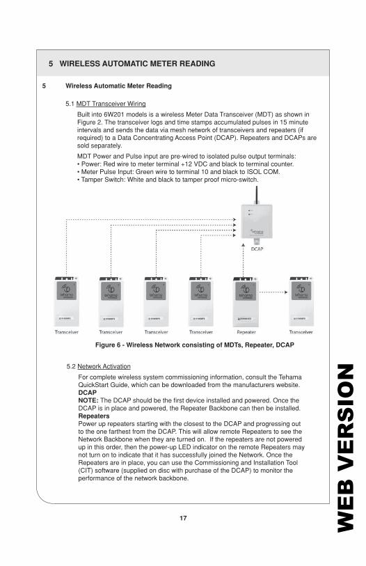
Figure 6 - Wireless Network consisting of MDTs, Repeater, DCAP
5 Wireless Automatic Meter Reading
5.1 MDT Transceiver Wiring
Built into 6W201 models is a wireless Meter Data Transceiver (MDT) as shown in Figure 2. The transceiver logs and time stamps accumulated pulses in 15 minute intervals and sends the data via mesh network of transceivers and repeaters (if required) to a Data Concentrating Access Point (DCAP). Repeaters and DCAPs are sold separately.
MDT Power and Pulse input are pre-wired to isolated pulse output terminals: • Power: Red wire to meter terminal +12 VDC and black to terminal counter. • Meter Pulse Input: Green wire to terminal 10 and black to ISOL COM. • Tamper Switch: White and black to tamper proof micro-switch.
WE
B V
ER
SIO
N

5 WIRELESS AUTOMATIC METER READING
18
Figure 7 - Tehama Wireless MDT
MDTs
After the Network is in place, you can begin to place the MDTs in their locations and turn them on. Alternatively the MDTs can also be installed with the meters while they are powered off. As soon as the meter begins to generate pulses, the first pulse will automatically turn on the MDT and begin to transmit.
Placement
CAUTIONS
• Like repeaters, MDTs should not be mounted inside a metal box or near a metal wall (i.e. heating furnace or electrical panel). Consult the Tehama QuickStart Guide, which can be downloaded from the manufacturers website.
• MDTs must be mounted using velcro, tie-wraps, or screws. Don’t let the MDT dangle by the pulse input wire.
• Avoid locations with dampness, high humidity, or an abundance of mold.
MDT and Repeater power-up
Power up the MDT so it can register with the DCAP. MDT’s must be wired to the meter described in Section 5.1 in order for the device to be operational.
The image below shows where an invisible button is on the wireless transceiver. Press that area of the MDT until you can feel the button click below your finger. The LED to the right of the ON/OFF button will provide feedback when the button is properly pushed.
• To turn the device ON, press and hold the ON/OFF button until the LED flashes off (about four seconds) then release the button.• After about 30 seconds the LED flash frequency will change from slow to fast. After
another 30 seconds, the LED will stay solid for 10 seconds then turn off, indicating the device is communicating with the network.
• To turn a device OFF, press and hold the ON/OFF button until the LED flashes off (about four seconds) then release the button. The LED will flash twice, indicating the device is OFF.
ON/OFFLED Indicator Light
WE
B V
ER
SIO
N
5 WIRELESS AUTOMATIC METER READING
19
Power-up LED Indications
Slow flash: The device is searching for a signal from a Beacons from a DCAP and/or Repeaters.
Rapid Flash: The device has received a signal from a DCAP or a repeater and is in the process of joining the Network.
Solid Flash: The device has successfully joined the Network.
After power up, if ON/OFF button is quickly pressed once, LED will indicate:
Single Flash: The device is in a light sleep mode. It will wake up periodically to listen for beacons.
Double Flash: The device is OFF
10 second on: The device is connected with a Network.
NOTE: When the device is ON but cannot connect with a radio network, it enters a light sleep mode. If no network is present, the device will continue to flash slowly for 90 seconds then return to sleep mode for some time before trying to connect to a signal again. If no network is in range, turn off the device so the battery will not drain.
WE
B V
ER
SIO
N

6 MAINTENANCE
Properly installed meters with correct connections and secure conduit fittings should not require user maintenance. If the meter is functioning abnormally, consult the FAQ/Troubleshooting guide. If the answer cannot be found there, contact Technical Support.
20 WE
B V
ER
SIO
N

7 TROUBLESHOOTING / FAQ
21
Q: What is AMR equipment?
A: AMR is Automatic Meter Reading equipment. This typically consists of radio transmitters, repeaters and a collector that monitors, records, and is capable of transmitting data to a third party billing service (residential billing company).
Q: Why are the current transformers color coded (Black and white, red and white, and blue and white)?
A: CT1 needs to monitor the same phase used to power the meter on line 1, CT2 needs to monitor the same phase used to power line 2. Color coding helps the installer maintain correct phasing.
Q: Can the meters be tampered with after installation?
A: The flush mount enclosures provide two drilled fillister head screws through which wire seals can be installed. Also, tamper-evident labels can be affixed to the cover after installation.
Q: Can voltage input wires and current transformer secondary leads be routed through the same conduit?
A: Yes, provided Leviton supplied CTs are used.
Q: I still can’t get my meter to work, what now?
A: Contact technical support via phone or at www.leviton.com
Problem Solution
1. LCD not illuminated • Check to make sure all connections are wired properly
• Test the voltage being supplied to the meter using an AC voltmeter
• With power off, remove any additional line fuses and test with ohmmeter
2. Load LED not flashing • Verify CT connections and orientations • Make sure there is sufficient load to draw a significant current • Test the voltage being supplied to the
meter using an AC voltmeter
3. Registered consumption low • Check to make sure the reverse phase arrow is not shown on the LCD
• Make sure that current and voltage connections are in phase.
• Check power connections and fuses
WE
B V
ER
SIO
N

8 WARRANTY
LIMITED 5 YEAR WARRANTY AND EXCLUSIONSLeviton warrants to the original consumer purchaser and not for the benefit of anyone else that this product at the time of its sale by Leviton is free of defects in materials and workmanship under normal and proper use for five years from the purchase date. Leviton’s only obligation is to correct such defects by repair or replacement, at its option. For details visit www.leviton.com or call 1-800-824-3005. This warranty excludes and there is disclaimed liability for labor for removal of this product or reinstallation. This warranty is void if this product is installed improperly or in an improper environment, overloaded, misused, opened, abused, or altered in any manner, or is not used under normal operating conditions or not in accordance with any labels or instructions. There are no other or implied warranties of any kind, including merchantability and fitness for a particular purpose, but if any implied warranty is required by the applicable jurisdiction, the duration of any such implied warranty, including merchantability and fitness for a particular purpose, is limited to five years. Leviton is not liable for incidental, indirect, special, or consequential damages, including without limitation, damage to, or loss of use of, any equipment, lost sales or profits or delay or failure to perform this warranty obligation. The remedies provided herein are the exclusive remedies under this warranty, whether based on contract, tort or otherwise.
FOR CANADA ONLYFor warranty information and/or product returns, residents of Canada should contact Leviton in writing at Leviton Manufacturing of Canada Ltd to the attention of the Quality Assurance Department, 165 Hymus Blvd, Pointe-Claire (Quebec), Canada H9R 1E9 or by telephone at 1 800 405-5320.
For Technical Assistance Call: 1-800-824-3005 - www.leviton.com
© 2018 Leviton Mfg. Co., Inc.
22 WE
B V
ER
SIO
N

9 CONTACT INFORMATION
Leviton Manufacturing Co., Inc. 201 N. Service Rd. Melville, NY 11747
Technical Assistance: 1-800-824-3005
23 WE
B V
ER
SIO
N

© 2018 Leviton Mfg. Co., Inc. DI-000-A3246-00A WE
B V
ER
SIO
N