mini circular - itt cannon mini circular mkj1 connectors the mkj1 is a robust connector meeting...
TRANSCRIPT

Min
i Circu
lar
ca_B1-B66.qxd:Layout 1 2/9/11 7:58 PM Page 1
B-40www.ittcannon.com
Dimensions shown in inches (mm)Specifications and dimensions subject to change
B
Min
i Cir
cula
rMKJ1 Connectors
The MKJ1 is a robust connector meeting MIL-DTL-38999shock and vibration requirements. Plug connector comeswith an anti-decoupling spring for vibration resistance. Idealfor harsh environments where a robust electrical connectionis required under the most demanding shock and vibrationconditions. Proven design for avionics, satellites, and missile systems.
Specifications
Contact Type Rear crimp or PCB mount
Contacts Size 23 (0.076" spacing), Size 16 (.177” spacing)
Wire Size #22 - #28 AWG (Size 23 Contacts), #16 - #20 AWG (Size 16 Contacts)
Contact Rating 5 Amps Maximum
Voltage Rating 500 VAC RMS sea level
Insulation Resistance 5,000 Megaohms minimum
Operating Temperature -55°C to +150°C
Contact Resistance 8 Milliohms maximum
Vibration 40 g’s in accordance with MIL-STD-1344 Method 2005, Condition IV
Shock 300 g’s in accordance with MIL-STD-1344 Method 2004, Condition E
Durability 2,000 mating cycles
Receptacle Mounting Jam nut or Wall Mount
EMI Shielding 40db attenuation, 100Mhz to 1000Mhz
Coupling Double Start Threaded
Materials Shells - Aluminum Alloy or Stainless SteelInsulators - ThermostaticSeals - FlurosiliconeContacts - Copper alloy with gold over nickel plating
ca_B1-B66.qxd:Layout 1 2/9/11 7:59 PM Page 40

B-41www.ittcannon.com
Dimensions shown in inches (mm)Specifications and dimensions subject to change
B
Min
i Circu
larMKJ1 Connectors
MKJ1 Plug (Banding Platform)
Socket Insert Pin Insert
MKJ1 PLUG DIMENSIONS
LAYOUT Ø A B THREAD(ACME DOUBLE START) Ø C
MAX WEIGHT IN GRAMS
PIN SOCKET6-4 .600 .375- .05P .1L -2B .290 5.0 5.5
6-7 .600 .375- .05P .1L -2B .290 5.1 5.5
7-10 .680 .4375- .05P .1L -2B .390 6.9 7.7
9-19 .810 .5625- .05P .1L -2B .500 9.4 10.9
13-37 1.050 .8125- .05P .2L -2B .650 18.9 21.7
ca_B1-B66.qxd:Layout 1 2/9/11 7:59 PM Page 41

B-42www.ittcannon.com
Dimensions shown in inches (mm)Specifications and dimensions subject to change
B
Min
i Cir
cula
rMKJ1 Connectors
Plug Connector Orientation Front Side
MKJ1 Plug Barrel Clocking Positions
BARREL CLOCKING
POSITION K1° K2°
A (NORMAL) 150° 210°
B 75° 210°
C 95° 230°
D 140° 275°
Master keyway remains stationary at topdead center for all sizes and clocking.
Note: Pin insert front side shown for reference only. Socket insert is a mirror image.
Barrel Clocking(A- Clocking Shown)
ca_B1-B66.qxd:Layout 1 2/9/11 7:59 PM Page 42

B-43www.ittcannon.com
Dimensions shown in inches (mm)Specifications and dimensions subject to change
B
Min
i Circu
larMKJ1 Connectors
Panel Cutouts
Socket Insert Pin Insert
MKJ1 JAM NUT RECEPTACLE DIMENSIONS
LAYOUT Ø AFLANGE DIA. B FLAT C FLATS D THREAD
(ACME DOUBLE START)E THREAD
UN-2A Ø FMAX WEIGHT IN
GRAMSPIN SOCKET
6-4 .635 .410 .595 .375- .05P .1L -2A .4375-2B .290 4.1 4.6
6-7 .635 .410 .595 .375- .05P .1L -2A .4375-2B .290 4.2 4.6
7-10 .755 .536 .723 .4375- .05P .1L -2A .5625-2B .390 6.2 7.0
9-19 .830 .596 .790 .5625- .05P .1L -2A .625-2B .500 7.8 9.3
13-37 1.078 .845 1.044 .8125- .1P .2L -2A .875-2B .650 14.6 17.3
SHELL, RECEPTACLE
LAYOUT H FLAT±.002 Ø J
6 - 4 .420 .448
6 - 7 .420 .448
7 - 10 .551 .573
9 - 19 .609 .635
13 - 37 .859 .885
MKJ1 Jam Nut Receptacle (Banding Platform)
ca_B1-B66.qxd:Layout 1 2/9/11 7:59 PM Page 43
B-44www.ittcannon.com
Dimensions shown in inches (mm)Specifications and dimensions subject to change
B
Min
i Cir
cula
r
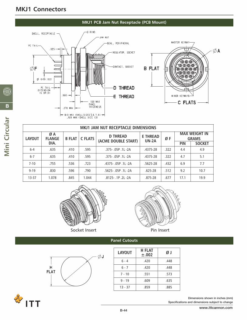
MKJ1 PCB Jam Nut Receptacle (PCB Mount)
MKJ1 Connectors
MKJ1 JAM NUT RECEPTACLE DIMENSIONS
LAYOUTØ A
FLANGEDIA.
B FLAT C FLATS D THREAD(ACME DOUBLE START)
E THREADUN-2A Ø F
MAX WEIGHT INGRAMS
PIN SOCKET6-4 .635 .410 .595 .375- .05P .1L -2A .4375-28 .322 4.4 4.9
6-7 .635 .410 .595 .375- .05P .1L -2A .4375-28 .322 4.7 5.1
7-10 .755 .536 .723 .4375- .05P .1L -2A .5625-28 .432 6.9 7.7
9-19 .830 .596 .790 .5625- .05P .1L -2A .625-28 .512 9.2 10.7
13-37 1.078 .845 1.044 .8125- .1P .2L -2A .875-28 .677 17.1 19.9
Panel Cutouts
Socket Insert Pin Insert
LAYOUT H FLAT±.002 Ø J
6 - 4 .420 .448
6 - 7 .420 .448
7 - 10 .551 .573
9 - 19 .609 .635
13 - 37 .859 .885
ca_B1-B66.qxd:Layout 1 2/9/11 7:59 PM Page 44

B-45www.ittcannon.com
Dimensions shown in inches (mm)Specifications and dimensions subject to change
B
Min
i Circu
larMKJ1 Connectors
Receptacle Connector Orientation Front Side
MKJ1 Receptacle Shell Clocking Positions
Master keyway is perpendicular with B Flat for all sizes and remains stationaryat top dead center for all clockings.
SHELL CLOCKING
POSITION K1° K2°
A (NORMAL) 150° 210°
B 75° 210°
C 95° 230°
D 140° 275°
Note: Socket insert front side shown for reference only. Pin insert is a mirror image.
Shell Clocking(A- Clocking Shown)
ca_B1-B66.qxd:Layout 1 2/9/11 7:59 PM Page 45