mimo in nr - ieeesite.ieee.org/swe-ctw/files/2019/06/nr-mimo-ctw2019-.pdf · mimo ›it is mainly a...
TRANSCRIPT

Claes Tidestav
NR multi-antenna

ERAMBIR Michael Birgersson | 2019-05-01 | Ericsson Internal | Page 2
› Benefits of multi-antenna transmissions:
– Increased signal strength, reduced interference, MU-MIMO
› In NR, all signals can be beamformed
– PDSCH, PUSCH, PDCCH, PUCCH, PBCH, PSS/SSS, CSI-RS, SRS,…
› Transmissions are (to a large extent) self-contained
– In-beam DM-RS for channel estimation – no reliance on broadcast pilots
› Procedures designed with beam-based transmission in mind:
– Initial access
– Mobility
NR – designed for multi-antenna
Commercial in confidence | © Ericsson AB 2019 | 2019-06-12

ERAMBIR Michael Birgersson | 2019-05-01 | Ericsson Internal | Page 3
› Fully digital antenna implementation may not be feasible
› Analog beamforming implies that gNB and/or UE can only
transmit/receive in one direction (beam) at any point in time
› Therefore only feasible to span selected directions of the
channel → One will need to rely on a limited number of
beams.
› Fully digital antenna implementation is feasible
› Digital beamforming makes it feasible to estimate the
entire channel by transmitting CSI-RS.
› Data can be transmitted with a narrow beam given the
estimated channel.
TWO classes of MIMO solutions
Low band High band
RS
Commercial in confidence | © Ericsson AB 2019 | 2019-06-12

ERAMBIR Michael Birgersson | 2019-05-01 | Ericsson Internal | Page 4
› Codeword:
– The coded bits corresponding to one transport block
– One codeword corresponds to one HARQ process
› Layer:
– One codeword is split over n layers (n=rank)
– One layer corresponds to one DM-RS port
› (Antenna) port:
– Where a reference signal is transmitted
Codeword, layer, port, …
Commercial in confidence | © Ericsson AB 2019 | 2019-06-12
ERAMBIR Michael Birgersson | 2019-05-01 | Ericsson Internal | Page 5
› NR has only a single transmission scheme for PDSCH
– One DMRS port per layer
› Any precoding can be used
– The UE only has to know how many layers are transmitted
› A UE can receive 1-8 layers
– For 1-4 layers PDSCH: One codeword
– For 5-8 layers PDSCH: Two codewords
PDSCH transmission
Commercial in confidence | © Ericsson AB 2019 | 2019-06-12

ERAMBIR Michael Birgersson | 2019-05-01 | Ericsson Internal | Page 6
› One method to determine the precoder
› gNB transmits CSI-RSs from multiple antenna ports
› UE evaluates several possible precoders, e.g., beams
– Precoders are chosen from a standardized codebook
› UE sends a recommended precoder to the gNB
› gNB applies the recommended precoder to transmit PDSCH
CODEbook-based transmission
Commercial in confidence | © Ericsson AB 2019 | 2019-06-12
CSI-RS 1,2
CSI-RS 3,4
CSI-RS 15,16P
reco
de
r
layer1
layer2
Recommend
PDSCH
ERAMBIR Michael Birgersson | 2019-05-01 | Ericsson Internal | Page 7
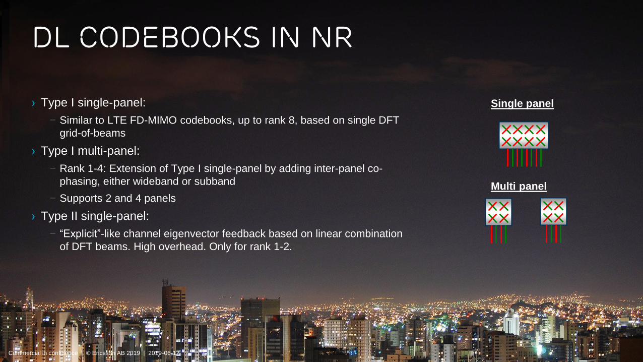
› Type I single-panel:
– Similar to LTE FD-MIMO codebooks, up to rank 8, based on single DFT
grid-of-beams
› Type I multi-panel:
– Rank 1-4: Extension of Type I single-panel by adding inter-panel co-
phasing, either wideband or subband
– Supports 2 and 4 panels
› Type II single-panel:
– “Explicit”-like channel eigenvector feedback based on linear combination
of DFT beams. High overhead. Only for rank 1-2.
DL codebooks IN NR
Single panel
Multi panel
Commercial in confidence | © Ericsson AB 2019 | 2019-06-12

ERAMBIR Michael Birgersson | 2019-05-01 | Ericsson Internal | Page 8
› With reciprocity-based precoding, DL CSI is acquired based on UL
SRS transmission
– Full channel information available, enabling more advanced precoding for MU-
MIMO
› It is mainly a proprietary feature; it can be implemented by using
components in the standard.
– Therefore not that visible in the standard.
› Reciprocity based and codebook based PDSCH both have their
strengths, even for TDD
Reciprocity based PDSCH transmission
Commercial in confidence | © Ericsson AB 2019 | 2019-06-12

ERAMBIR Michael Birgersson | 2019-05-01 | Ericsson Internal | Page 9
Do we see any gains from larger antennas?
0%
7%
12%14%
18%
0%
14%
27%
33%
49%
0%
10%
20%
30%
40%
50%
60%
16 ports 20 ports 24 ports 28 ports 32 ports
Mean user throughput gain (%)
Cell-edge user throughput gain (%)
Micro scenario, type I feedback
0%
9%
16%19%
21%
0%
20%
38%
45%
54%
0%
10%
20%
30%
40%
50%
60%
16 ports 20 ports 24 ports 28 ports 32 ports
Mean user throughput gain (%)
Cell-edge user throughput gain (%)
Macro scenario, type I feedback
16 ports
32 ports
Commercial in confidence | © Ericsson AB 2019 | 2019-06-12
ERAMBIR Michael Birgersson | 2019-05-01 | Ericsson Internal | Page 10
› A UE can transmit 1-4 layer PUSCH and use up to 4 Tx chains
– A single codeword is used
› CP-OFDM waveform is used
– DFT-S-OFDM additionally supproted for coverage extenstion
› Only for single layer
› Codebook-based precoding and non-codebook based precoding (~reciprocity)
PUSCH is supported
multi antenna - PUSCH
Commercial in confidence | © Ericsson AB 2019 | 2019-06-12

ERAMBIR Michael Birgersson | 2019-05-01 | Ericsson Internal | Page 11
A typical use case would be
1. A UE transmits one or two SRS resources
– An SRS resource has 1,2 or 4 ports
2. gNB indicates
– SRS resource indicator (SRI), and
– TPMI and TRI (UE precoder matrix from a precoder
codebook and rank)
3. The UE performs PUSCH transmission
Codebook based PUSCH transmission
SRS resource 1
SRS resource 2
SRS resource 1
SRS resource 2
SRI=2, TPMI=1
TPMI=1
TPMI=2
SRI=2, TPMI=1
PUSCH
Commercial in confidence | © Ericsson AB 2019 | 2019-06-12

ERAMBIR Michael Birgersson | 2019-05-01 | Ericsson Internal | Page 12
A typical use case would be
1. A CSI-RS can be indicated to UE for assisting
calculating UL precoder (using DL-UL
reciprocity)
2. A UE transmits up to four SRS resources
– Each SRS resource is one port and corresponds to a
PUSCH layer
3. gNB indicates
– Multiple SRS resource indicators (SRIs)
– Number of SRIs = rank
4. The UE performs PUSCH transmission
Non-Codebook based PUSCH transmission
SRS resource 1
SRS resource 2
SRS resource 1
SRS resource 2
SRI=2
PUSCH
CSI-RS
Commercial in confidence | © Ericsson AB 2019 | 2019-06-12

ERAMBIR Michael Birgersson | 2019-05-01 | Ericsson Internal | Page 13
› In mmW, analog antenna architectures will be common
› The gNB/UE will transmit/receive all signals in beams
– Omni-directional transmission/reception will not be possible
› In particular, the UE can only receive signals from one direction at a
time
– Need to prepare to receive from another direction
beam management
Commercial in confidence | © Ericsson AB 2019 | 2019-06-12

ERAMBIR Michael Birgersson | 2019-05-01 | Ericsson Internal | Page 14

ERAMBIR Michael Birgersson | 2019-05-01 | Ericsson Internal | Page 15
› The system ensures that the beams in the gNB and the UE are aligned
› Procedures for updating beams at the gNB/UE are supported
› Primarily based on UE measurements on DL reference signals
– Either CSI-RS or SSB
– UE uses the same beam for transmission as for reception, the gNB uses the same
beam for reception as for transmission – beam correspondence
› P1 procedure: beam finding
P2 procedure: Tx beam refinement
P3 procedure: Rx beam refinement
beam management procedures
“P1 procedure”
“P2 procedure”
“P3 procedure”

ERAMBIR Michael Birgersson | 2019-05-01 | Ericsson Internal | Page 16
› Before the network changes its Tx beam, it (sometimes) sends a
beam indication to the UE
– To support the update of the UEs RX beams
› Points to a previously received reference signal
› For the reception of all DL signals:
– PDCCH
– PDSCH
– CSI-RS
› Signaled to the UE in different ways for different signals:
– DCI, MAC CE, RRC
Beam indication
PDSCH in beam 1 (RS1)
Two possible Tx beams
Commercial in confidence | © Ericsson AB 2019 | 2019-06-12

ERAMBIR Michael Birgersson | 2019-05-01 | Ericsson Internal | Page 17
A typical use case would be
1. The network communicates with the UE using a certain
Tx beam, and the UE uses a certain Rx beam
2. The network transmits CSI-RS in a set of candidate
beams – UE reports the best
3. Network starts transmitting PDSCH in new beam
4. The network repeats CSI-RS in one beam
5. The UE varies its Rx beam
6. The UE chooses the best Rx beam
Beam management: Typical use caseBeam management: Typical use case
Commercial in confidence | © Ericsson AB 2019 | 2019-06-12

ERAMBIR Michael Birgersson | 2019-05-01 | Ericsson Internal | Page 18
› Needed only if UE does not have beam correspondence
– When a UE has beam correspondence, it may derive the UL TX beam from the DL RX beam
› UL beam management is based on SRS beam sweeps
› U1,U2,U3 procedures analogous to P1,P3,P2 procedures
› The framework for UL beam management is in general similar to DL beam
management framework
UL Beam management
Commercial in confidence | © Ericsson AB 2019 | 2019-06-12

ERAMBIR Michael Birgersson | 2019-05-01 | Ericsson Internal | Page 19
› NR designed for multi-antenna transmissions
– All procedures adapted
– All channels can be beam-formed
– All transmissions are self-contained
› For determination of PDSCH precoders, NR supports
– Codebook-based transmission with up to 32 ports
– Type I and type II codebooks
– Reciprocity-based transmission – based on SRS
› NR supports codebook based and non codebook based PUSCH transmission
› Beam management procedures have been introduced targeting high band operation
Summary
Commercial in confidence | © Ericsson AB 2019 | 2019-06-12