milton heights sewage pumping station draft preliminary ... · halton region milton heights sewage...
TRANSCRIPT

Halton Region
Milton Heights Sewage Pumping Station Draft Preliminary Design Report Version 1.1 ▪ October 2013 ▪ File 13147
Prepared on behalf of:
Milton Heights Developers Group
c/o Davis Webb 24 Queen Street East, Suite 800
Brampton, ON L6V 1A3

this report has been formatted for double-sided printing

Milton Heights Sewage Pumping Station Preliminary Design Report
Halton Region ________________________________________________________________________________________________________ Version 1.1 ▪ October 2013
THE MUNICIPAL INFRASTRUCTURE GROUP LTD ____________________________________________________________________________ PAGE iii
Revision Log
REVISION DATE ISSUE / REVISION DESCRIPTION 1.0 October 2013 Draft Submission
1.1 October 2013 Submission for Approval


Milton Heights Sewage Pumping Station Preliminary Design Report
Halton Region ________________________________________________________________________________________________________ Version 1.1 ▪ October 2013
THE MUNICIPAL INFRASTRUCTURE GROUP LTD ____________________________________________________________________________ PAGE v
Contents
Revision Log ................................................................................... iii Signature Page ................................................................................ iv 1 Introduction ......................................................................... 1
1.1 Background ............................................................... 1 2 Project Description .............................................................. 2
2.1 Site Description ......................................................... 2 2.2 Sanitary Drainage Area ............................................. 2 2.3 Pumping Station Design Features ............................. 3 2.4 Ultimate / Expansion Considerations of the
Sewage Pumping Station .......................................... 5 2.5 Inlet Sewers .............................................................. 5 2.6 Emergency Sanitary Overflow Infrastructure ............. 5
3 Site Works ............................................................................ 5 3.1 General Topography and Site Drainage .................... 5 3.2 Forcemain ................................................................. 5 3.3 Access and Parking Area .......................................... 5
4 Process ................................................................................ 6 4.1 Wet Well ................................................................... 6 4.2 Sewage Pumps ......................................................... 7 4.3 Forcemain ............................................................... 11 4.4 Station Piping .......................................................... 12 4.5 1 Hour Emergency Storage ..................................... 12
5 Odour Control System....................................................... 13 6 Site Description ................................................................. 13
6.1 Site Access and Egress .......................................... 13 7 Standby Generator ............................................................ 14 8 Construction ...................................................................... 14
8.1 Environmental Protection Measures ........................ 14 8.2 Shoring and Dewatering .......................................... 14
9 Approvals ........................................................................... 15 10 Preliminary Design Drawings ........................................... 15

Milton Heights Sewage Pumping Station Draft Preliminary Design Report Halton Region Version 1.1 October 2013______________________________________________________________________________________________________ __
PAGE vi _____________________________________________________________________________ THE MUNICIPAL INFRASTRUCTURE GROUP LTD
Appendices
Appendix A: Landowner’s Plan
Appendix B: Sanitary Drainage Plan, Wastewater Servicing Plan & Sanitary Design Sheet
Appendix C: Halton Region Water and Wastewater Facilities Design Manual – Sewage Pumping Stations
Appendix D: Equivalent Lengths, Headloss and TDH, Surge & Net Positive Suction Head Calculations
Appendix E: Pump Selection and Performance Curve
Figures
Figure 4-1: Proposed System Curve .................................. 10
Tables Table 2-1: Peak Flow to the Proposed Pumping Station under Initial Condition ............................................... 2 Table 2-2: Peak Flow to the Proposed Pumping Station under Ultimate Condition .......................................... 3 Table 4-1: Pump Control Levels ........................................... 7 Table 4-2: Forcemain Sizing Rationale ............................... 11 Table 4-3: 1-Hour Emergency Storage Summary under the Future and Ultimate Design Conditions ............... 13

Milton Heights Sewage Pumping Station Draft Preliminary Design Report
Halton Region _____________________________________________________________________________________________________ Version 1.1 ▪ October 2013
THE MUNICIPAL INFRASTRUCTURE GROUP LTD ____________________________________________________________________________ PAGE 1
1 Introduction
1.1 Background
The Milton Heights Landowner’s Development Group, via the RAND Engineering Corporation, has retained TMIG to conduct the preliminary design of a sanitary sewage pumping station (SPS) to service portions of the Milton Heights Neighbourhood development, within Halton Region.
The proposed Milton Heights Neighbourhood development consists of approximately 125 hectares of land, bounded to the north by King’s Highway No. 401, to the east by Peru Road, to the south and west by Steeles Avenue and the Canadian Pacific Railway, and to the west by Tremaine Road. Refer to Appendix A for the Landowner’s Plan of the proposed development. This area also contains a significant amount of existing lands in which the current residents are service by local/private septic system.
Based on the technical information provided by Halton Region, the development of the Milton Heights Neighbourhood is included in the designated service area of the Milton Wastewater Treatment Plant (WWTP). As a result of the recent modifications to the WWTP, the capacity is available for allocation of infilling to the Milton Heights Landowners Group lands and the existing residential area within the Milton Heights Neighbourhood. The modifications will accommodate Best Planning Estimates of growth for the designated service area. The proposed expansion of the wastewater system will allow the option of connecting existing homes thus eliminating aging local/private septic systems.
Based on RAND Engineering’s technical evaluation of the existing grading conditions for the portion of the Milton Heights Neighbourhood located south of NW-1-A and north of the CPR rail line (i.e., the Andrin property and a portion of the Douglas & Shirley Walmsley and Tarlock Sandhu properties), a recently constructed 675 mm diameter wastewater main on Market Drive is too shallow to service the subject lands by gravity. Refer to Appendix B for the Sanitary Wastewater Servicing Plans and Design Sheets. As such, the proposed wastewater system will be designed as a combination of conventional gravity sewers, and forcemain systems, complete with a sanitary sewage pumping station. This report presents the preliminary technical details of the proposed sanitary sewage pumping station, assumptions used in the design for both the interim service conditions of the proposed development, as well as the ultimate design conditions when the existing residential units within the sanitary catchment area are connected to the municipal sanitary servicing infrastructure (i.e., removed from local septic sewers).
As shown in Appendix B, sanitary sewage flows from the Andrin subdivision and future development lands will be conveyed by gravity to a proposed permanent sanitary sewage pumping station located within the Andrin property, on the west side of Peru Road. The sanitary sewage pumping station will convey sewage via a 200mm diameter proposed forcemain system on Peru Road to a 675 mm diameter trunk sewer on Market Drive. The proposed sanitary pumping station will be designed to service the following conditions:
• The interim design condition which includes the Andrin property and a portion of the Douglas & Shirley Walmsley and Tarlock Sandhu properties (Area 6, Appendix B), north of Steeles Ave. West, west of Peru Rd., and east of the Canadian Pacific Railway.
• The ultimate design condition which includes existing lands within the proposed neighbourhood development currently serviced by local/private septic systems as well as future development north of the Andrin lands and existing un-serviced lands along Peru Rd (i.e., Areas 5 and 7).

Milton Heights Sewage Pumping Station Draft Preliminary Design Report Halton Region Version 1.1 October 2013_________________________ _____________________________________________________________________________
PAGE 2 ______________________________________________________________________________ THE MUNICIPAL INFRASTRUCTURE GROUP LTD
The pumping station building features are designed to service both the interim and ultimate development conditions.
Under the interim development condition, proposed developments in the Andrin (Milton) Properties Ltd. lands and areas to the north (Area 6), will equate to an equivalent population of 1,610 people to be serviced. The pumping requirement for the interim development condition is a peak sanitary flow of 23.2 L/s.
Under the ultimate development condition, the interim development lands (Area 6) in addition to lands north of the interim condition lands and north of the Canadian Pacific Railway (Area 5), plus existing residential lands to the north and east along Peru Rd. (Area 7). These lands equate to an equivalent population of 2,876 people to be serviced. The pumping requirement for the future development condition is a peak sanitary flow of 42.3 L/s.
2 Project Description
2.1 Site Description
The proposed Milton Heights Sewage Pumping Station (SPS) will be located on the west side of Peru Rd., approximately 360 m north of Steeles Ave. West in Milton, Ontario. Access to the pumping station site will be from Peru Rd.
2.2 Sanitary Drainage Area
The Milton Heights SPS will be designed to accommodate flows based on a wastewater flow generation rate of 275 Lpcd as per Halton Region design standards.
Interim Condition – Sewage Pumping Station
Under the interim condition, the Milton Heights SPS will receive flows from the Andrin (Milton) Properties Ltd. lands and lands to the north, located north of Steeles Ave. West, west of Peru Rd., and east of the Canadian Pacific Railway (Area 6). The generation of the peak design flow from the proposed development under the initial condition is summarized in Table 2-1.
Table 2-1: Peak Flow to the Proposed Pumping Station under Initial Condition
Area Description Area to be Developed
(Ha) Equivalent Population
Average Daily Flow
(L/s)
Harmon Peaking Factor
Infiltration (L/s) (1)
Peak Flow (L/s)
Area 6 Andrin (Milton) Properties Ltd. lands and lands to the north (north of Steeles Ave. West, west of Peru Rd., and east of the CPR)
15.6 1610 5.12 3.66 4.46 23.20
Notes: 1. The infiltration flowrate was based on 0.286 L/s/ha, which is in accordance with Halton Region’s design
standards.
The equivalent population for the Area 6 lands was taken from the Sanitary Sewer Design sheet dated January 15, 2009, provided by the Rand Engineering Corporation.

Milton Heights Sewage Pumping Station Draft Preliminary Design Report
Halton Region _____________________________________________________________________________________________________ Version 1.1 ▪ October 2013
THE MUNICIPAL INFRASTRUCTURE GROUP LTD ____________________________________________________________________________ PAGE 3
Ultimate Condition – Sewage Pumping Station
Under the ultimate condition, the Milton Heights SPS will continue to receive flows from the Andrin (Milton) Properties Ltd. lands and lands to the north (Area 6), as well as lands north of the interim condition lands and north of the Canadian Pacific Railway (Area 5), plus existing residential lands to the north and east along Peru Rd. (Area 7). Peak design flows from the proposed developments as well as flow contributions from existing un-serviced lands under the ultimate condition are summarized in Table 2-2.
Table 2-2: Peak Flow to the Proposed Pumping Station under Ultimate Condition
Area Description Area to be Developed
(Ha) Equivalent Population
Average Daily Flow
(L/s)
Harmon Peaking Factor
Infiltration (L/s) (1)
Peak Flow (L/s)
Area 6 Andrin (Milton) Properties Ltd. lands and lands to the north (north of Steeles Ave. West, west of Peru Rd., and east of the CPR)
15.6 1610 5.12 3.66 4.46 23.20
Area 5 lands north of the interim condition lands (north of the CPR)
11.0 677 2.16 3.90 3.15 11.57
Area 7 existing residential lands to the north and east (along Peru Rd.)
10.7 589 1.87 3.94 3.06 10.43
Total 37.3 2,876 42.33 3.46 10.67 42.33
Notes: 1. The infiltration flowrate was based on 0.286 L/s/ha, which is in accordance with Halton Region’s design
standards.
The equivalent population for the Area 5, 6, and 7 lands was taken from the Sanitary Sewer Design sheet dated January 15, 2009, prepared by Trow Associated Inc., and provided by Rand Engineering Corporation.
Appendix B shows a plan of the sanitary catchment areas used to generate design flows for the area bounded by Highway 401, Tremaine Rd., the Canadian Pacific Railway, Steeles Ave. West, and Peru Rd., with areas 5, 6, and 7 being serviced by the Milton Heights SPS in the ultimate condition.
2.3 Pumping Station Design Features
The proposed station will be a dry pit and wet well type facility within a ±8.5 m wide by ±12.3 m long building approximately 15.5 m deep, interior dimensions. The main design features include:
A ±3.1 metre by ±6 metre cast-in-place concrete wet well with the following features:
300 mm diameter PVC inlet sewer A single wet well cell complete with the following:
• Basket screen to remove suspended solids

Milton Heights Sewage Pumping Station Draft Preliminary Design Report Halton Region Version 1.1 October 2013_________________________ _____________________________________________________________________________
PAGE 4 ______________________________________________________________________________ THE MUNICIPAL INFRASTRUCTURE GROUP LTD
• Ultrasonic level transmitter in each cell for redundancy and Flygt floats for back-up pump control
Accessible from grade by an access ladder to 3 intermediate platform levels and extension to the finished floor
Ductile iron (DI) pump suction piping Potable water close by and well washer system for cleansing/flushing Aluminum or fibreglass reinforced plastic platforms and gratings, with access to the
basket screen Lighting Class 1 Zone 1 electrical classification Mechanical ventilation for entry only 1 hour of initial emergency storage required on-site of 155 m3, to mitigate basement
flooding measured against the lowest estimated residential dwelling within subdivision at an elevation of 204.50 m.
A 300 mm diameter emergency overflow pipe, complete with maintenance hole and area-velocity radar flow meter for overflow indication and totalization.
Aluminum access hatches for basket screen removal, and access/egress
A ±6.0 metre by ±7.3 metre cast-in-place concrete dry-pit, formed in conjunction with the wet well, with the following features:
Accessible from grade by stair access down to the dry pit level Two (2) dry pit submersible pumps (one (1) duty, one (1) standby), with a future spatial
allocation for a third future pump and piping arrangement to accommodate future ultimate flows
Swing flex check valves Plug valves for isolation Aluminum access hatches for pump removal DI pump discharge piping and associated isolation valves (plug valves), flow meter
(mag meter) and pressure transmitter A pressure gauge on each pump discharge header An air release valve on the common discharge header Sump pit and pumps Level sensing element Continuous ventilation at 6 air changes per hour
A main level in the building with:
A control room housing the control panel, motor control center (MCC), the standby power generator and diesel fuel tank. The generator will be sized to power both pumps
Concrete containment area for the fuel tank An air cooled gen set The wet well will house the odour control unit
An on-site drain / bypass maintenance hole with:
A 300 mm diameter PVC outlet sewer with stainless steel slide gate and connection to the wet well
A 300 mm diameter PVC outlet sewer with connection to the proposed stormwater management pond
An on-site overflow maintenance hole with:
Flow meter (area velocity radar) A 300 mm diameter PVC outlet sewer with concrete headwall and tideflex check valve
at connection to the proposed wetland
Milton Heights Sewage Pumping Station Draft Preliminary Design Report
Halton Region _____________________________________________________________________________________________________ Version 1.1 ▪ October 2013
THE MUNICIPAL INFRASTRUCTURE GROUP LTD ____________________________________________________________________________ PAGE 5
2.4 Ultimate / Expansion Considerations of the Sewage Pumping Station
A third dry pit submersible pump and associated piping and valving to service the ultimate design capacity,
Upgrades to the standby power generator, with air intake and exhaust louvers and dampers sized for the ultimate design condition.
2.5 Inlet Sewers
The inlet sewers for the development of the Andrin (Milton) Properties Ltd. lands have been designed at a preliminary level by Rand Engineering. The inlet sewer to the pump station as provided by Rand Engineering is 250 mm diameter PVC pipe at an elevation of 199.234 m. The inlet sewer connects to the 1500 mm diameter Inlet/Bypass Maintenance Hole No. 1 which connects to the pumping station wet well via a 300 mm diameter PVC pipe.
2.6 Emergency Sanitary Overflow Infrastructure
The sewage pumping station site has also been equipped with emergency overflow infrastructure in the event of a catastrophic failure of the entire pumping station, consisting of the following:
• 300 mm diameter sanitary overflow pipe @ 1.1% (minimum) which has a capacity of 102 L/s.
• 1500 mm diameter Overflow Maintenance Hole No. 2, complete with area velocity radar flow meter for overflow indication and totalization.
3 Site Works
3.1 General Topography and Site Drainage
The existing ground at the proposed Milton Heights SPS site drains west toward a proposed stormwater management pond. The proposed site grading will match existing grades when and where ever possible and drainage will generally be away from the SPS building.
The proposed grade of the SPS site fronting Peru Rd., including the entrance access road for the pumping station, will be set to match the requirements of Halton Region. The parking area for the SPS was sloped 0.5% from the pumping station building. The finished floor of the pumping station was set 150 mm greater than the elevation of the parking area.
3.2 Forcemain
A 200 mm DR11 HDPE diameter forcemain is required for the Milton Heights SPS. The forcemain will run from the SPS approximately 580 metres northwest, and will discharge into the existing MH1A on Peru Rd. at the Market Drive easement, north of Sixteen Mile Creek.
A bypass connection will be provided for the forcemain within the property limits of the SPS to facilitate by-passing of the SPS during emergencies or major modifications.
The forcemain is discussed further in Section 4.3.
3.3 Access and Parking Area
The main access to the pumping station will be on the northeast side of the building fronting on Peru Rd. The driveway and parking area will be asphalt.

Milton Heights Sewage Pumping Station Draft Preliminary Design Report Halton Region Version 1.1 October 2013_________________________ _____________________________________________________________________________
PAGE 6 ______________________________________________________________________________ THE MUNICIPAL INFRASTRUCTURE GROUP LTD
4 Process
The proposed dry pit equipment (including the diesel genset) and instrumentation are designed for the initial peak flow of 23.2 L/s. The proposed pump station building and major civil works are designed for the ultimate peak flow rate of 42.3 L/s. The proposed sewage pumps and piping are designed for both initial and ultimate conditions.
4.1 Wet Well
The wet well is a single rectangular cast-in-place structure sized to accommodate the ultimate operating levels at the future design capacity of the SPS – 42.3 L/s. The single celled wet well will also be designed to accommodate 1 hour of emergency storage at the ultimate design capacity of the SPS – 42.3 L/s, as per Halton Region’s standards.
4.1.1 Minimum Wet Well Operating Depth
The wet well will have a cross sectional area of approximately ± 18.6 m2.
The proposed pumping station will include two pumps (1 duty, 1 standby) for the interim condition, with a firm capacity of 23.2 L/s. The proposed pumping station will be designed to accommodate one more pump in the future when the ultimate capacity of the SPS is realized at 42.3 L/s.
Based on the Ontario Ministry of Environment (MOE) criteria and pump manufacturers guidelines, the wet well must contain sufficient volume to allow a minimum ten minute pump cycle time. The required volume between pump starts is calculated as follows:
Volume (m3) = θ × Q / 4
Where: θ = time of one pumping cycle (min)
Q = Pump capacity of the largest duty pump (m3/min)
When: θ = 10 min
Q(1Pmp) = 42.3 L/s / 2 pumps = 1.29 m3/min
Volume @ Q(1Pmp) = (10 min • 1.29 m3/min) / 4 = 3.23 m3
Based on the size of the proposed wet well, the minimum operating depth required to ensure adequate pump cycle time becomes:
Operating depth @ Q(1Pmp)
H = (Volume @ Q(1Pmp)) / (Awetwell)
H = (3.23 m3) / (18.6 m2)
H = 0.17 m, Estimate for design purposes at 0.2 m.
The total depth between the duty pump start and stop elevation (for the design of the wet well’s ultimate capacity) should therefore be a minimum 0.2 m.

Milton Heights Sewage Pumping Station Draft Preliminary Design Report
Halton Region _____________________________________________________________________________________________________ Version 1.1 ▪ October 2013
THE MUNICIPAL INFRASTRUCTURE GROUP LTD ____________________________________________________________________________ PAGE 7
4.2 Sewage Pumps
A two pump system (one duty, one standby) will be used to achieve the firm initial capacity of 23.2 L/s. These pumps will be facilitated with an additional pump when the ultimate design capacity of the SPS is realized.
4.2.1 Operating Levels
The anticipated initial pump control levels are presented in Table 4-1.
Primary pump control is an ultrasonic level transmitter, with backup control by floats.
Table 4-1: Pump Control Levels
Float Controls Elevations Ultrasonic Controls
INV of 300 mm Inlet Sewer
at Wet Well 199.234
HWL Alarm 198.93
Start Pump 3 (future) 198.63
Start Pump 2 198.33
Start Pump 1 198.03
197.73 Start Lag Duty Pump (future)
197.43 Start Lead Duty Pump
197.13 Stop Lag Duty Pump (future)
196.83 Stop Lead Duty Pump
Stop All Pumps / LWL Alarm 196.53
Finished Floor of Wet Well
196.00
Notes: 1. HWL – High Water Level. LWL – Low Water Level.
The control hierarchy for the station will be based on LOCAL, CENTRAL MANUAL and AUTO modes of operation.
4.2.2 System Curve Calculations
The pump system curve was developed based on the use of a single 200 mm diameter forcemain from the SPS to the discharge point. The total dynamic head (TDH) for the Milton Heights SPS was calculated at various flow rates, where:
TDH (m) = static head (m) + friction losses (m)
Static Head
Based on the proposed operating levels in the wet well for ultimate conditions and the highest elevation in the forcemain being 207.03 m at the discharge point, the static heads for the system are as follows:
Minimum Static Head = 207.03 m - HWL

Milton Heights Sewage Pumping Station Draft Preliminary Design Report Halton Region Version 1.1 October 2013_________________________ _____________________________________________________________________________
PAGE 8 ______________________________________________________________________________ THE MUNICIPAL INFRASTRUCTURE GROUP LTD
= 207.03 m – 197.43 m
= 9.60 m
Mid Static Head = 207.03 m – MWL
= 207.03 m – 197.13 m
= 9.90 m
Maximum Static Head = 207.03 m - LWL
= 207.03 m – 196.83 m
= 10.20 m
Friction Losses
Friction losses are calculated using the Hazen-Williams equation as follows:
Friction losses, hf = (10.654 • Le • Q1.852)/(D4.8655 • C1.852)
Where: Le = equivalent length of pipe, m
Q = flow, m3/s
C = friction coefficient
D = diameter, m
Friction losses were calculated as hf from the suction bell of Pump 1 to the discharge point of the forcemain.
The equivalent length (Le) is calculated by converting all the pipe lengths of different pipe sizes, fittings and appurtenances to an equivalent length of a single pipe size. The Equivalent Lengths Calculation Sheet in Appendix D presents the equivalent length of all the pipes, fittings and appurtenances in the Milton Heights SPS.
Once the equivalent length of pipe was determined, friction losses were then calculated at different ‘C’ factors to assess the system characteristics at various times of the design life:
A ‘C’ factor of 120 in conjunction with the low water level in the wet well was used to calculate the “worst case” system curve, as may occur in the future after long term use of the forcemain.
A ‘C’ factor of 130 in conjunction with the mid water level in the wet well was used to calculate the design system curve, which is most likely to occur during the use of the forcemain.
A ‘C’ factor of 140 in conjunction with the high water level in the wet well was used to calculate the system curve during the initial start-up of the pumping station to ensure that cavitation is not a concern.
Friction losses from the suction bell to Pump 1 to the discharge point of the forcemain were calculated for hf at various flowrates and for the three ‘C’ Factors using the Hazen-Williams equation when:

Milton Heights Sewage Pumping Station Draft Preliminary Design Report
Halton Region _____________________________________________________________________________________________________ Version 1.1 ▪ October 2013
THE MUNICIPAL INFRASTRUCTURE GROUP LTD ____________________________________________________________________________ PAGE 9
D = 0.200 m and Le = 826.2 m
Total Dynamic Head (TDH)
The total dynamic head (TDH) is calculated by adding the static head to the friction losses. During initial flows, the static head in the system at low, mid and high water level would be 10.20 m, 9.90 m and 9.60 m, respectively. Therefore, the total dynamic head for each system curve was calculated as follows:
@ C = 120, TDH = 10.20 m + Σhf
@ C = 130, TDH = 9.90 m + Σhf
@ C = 140, TDH = 9.60 m + Σhf
The Equivalent Lengths Calculation Sheet in Appendix D presents the friction loss calculations and results TDH using a 200 mm diameter forcemain.
The resulting system curve for a 200 mm diameter forcemain at each of the ‘C’ factors of 120, 130, and 140 is presented in Figure 4-1.
4.2.3 Pump Selection
As illustrated in Figure 4-1, the pumps selected must be capable of meeting the design point of 23.2 L/s at 12.4 m TDH.
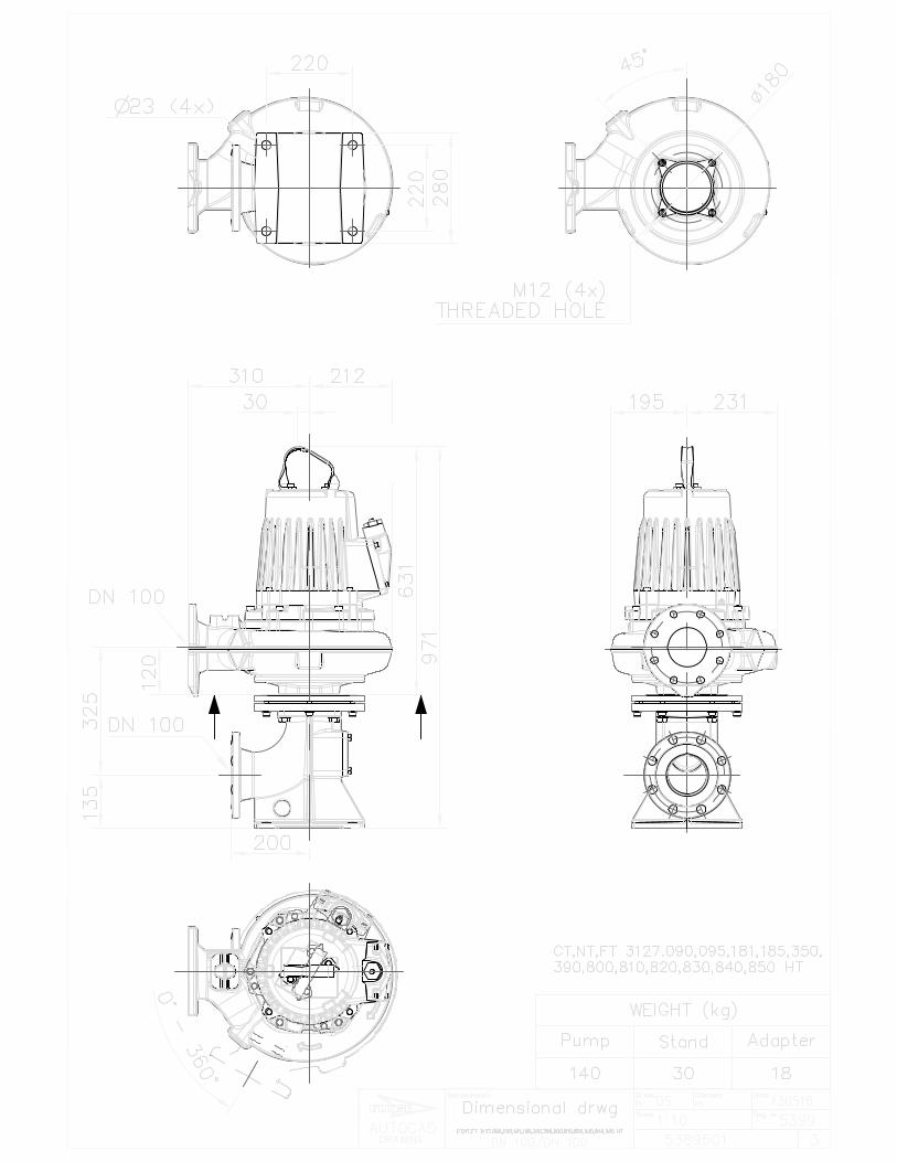
A suitable pump to meet the design point is the FLYGT NT3127.181, 5.5 kW, 60 Hz with a 195 mm diameter impeller. The pumps are inverter duty rated and are each equipped with a VFD motor. The information concerning this pump has been provided in Appendix E.
4.2.4 NPSHa
The Net Positive Suction Head available (NPSHa) for the pumping station has been determined to be 9.89 m, 10.19 m and 10.49 m (at the low, mid and high operating levels, respectively) as presented in Appendix D. As a result, the pumps selected should be able to provide flows across the pump and system curve without exceeding the minimum NPSH available of 9.89 m.
The FLYGT NT3127.181 60 Hz pump(s) proposed have a NPSH requirement of 4.0 m at the design point. Therefore, these pumps will operate satisfactorily based on the NPSHa.

Milton Heights Sewage Pumping Station Draft Preliminary Design Report Halton Region Version 1.1 October 2013_________________________ ___________________________________________________________________________________________________________
PAGE 10 _______________________________________________________________________________________________________________________________ THE MUNICIPAL INFRASTRUCTURE GROUP LTD
Figure 4-1: Proposed System Curve

Milton Heights Sewage Pumping Station Draft Preliminary Design Report
Halton Region _____________________________________________________________________________________________________ Version 1.1 ▪ October 2013
THE MUNICIPAL INFRASTRUCTURE GROUP LTD ___________________________________________________________________________ PAGE 11
4.3 Forcemain
4.3.1 Forcemain
MOE guidelines recommend sizing any forcemain to maintain velocities between 0.6 m/s and 3.0 m/s to provide scouring velocity, minimize headloss, and reduce pump power requirements. It was determined that a single 200 mm diameter forcemain can service both the initial and ultimate development conditions. Table 4-2 summaries the velocities in various diameter forcemains for the interim and ultimate flow scenarios.
Table 4-2: Forcemain Sizing Rationale
Proposed Forcemain 150 mm (6”) DR11 HDPE
200 mm (8”) DR11 HDPE
250 mm (10”) DR11 HDPE
Flow Scenario Flow (L/s)
Velocity (m/s)
Interim Condition
Design Flowrate 23.2 1.39 0.94 0.61
Projected Flowrate @ C = 140 25.5 1.76 1.04 0.67
Ultimate Condition
Ultimate Design Flowrate 42.3 2.58 1.76 1.14
Under the interim development condition, the pump flow achieves desirable MOE design guidelines velocities (0.6 – 1.1 m/s, 3 m/s maximum) at the design flowrate of 23.2 L/s in a 200 mm or 250 mm diameter forcemain. The 200 mm and 250 mm diameter forcemains for the ultimate design conditions of 42.3 L/s will yield a scouring velocity of 1.76 m/s and 1.14 m/s respectively. The 150 mm diameter forcemain achieves velocities at the higher end of the desirable MOE range for the interim and ultimate conditions. The disadvantages of using such a forcemain size are premature wear on the forcemain due to high scouring velocities, which may result in the forcemain not realizing its ultimate design life, as well as increased friction losses and TDH requirements for the pumps. As a result, TMIG recommends a 200 mm forcemain which will have more suitable velocities for the future and ultimate design flowrates, and will also be less costly than a 250 mm forcemain.
Considering that the 200 mm forcemain will be new, it is more appropriate to examine the projected flow rate at a C factor of 140, which is the realistic C factor for the new forcemain. At a C factor of 140 the flow is 25.5 L/s, as can be seen from the system curve presented in Figure 4-1. At 27 L/s, a 200 mm diameter forcemain yields acceptable scouring velocities as per the MOE design guidelines. At the ultimate design flowrate, a forcemain with a diameter of 200 mm yields a scouring velocity of 1.76 m/s, which is in the middle range of the MOE recommended guidelines.
Therefore, a 200 mm DR11 HDPE diameter forcemain is considered the optimal size selection for the Milton Heights SPS for both the interim and the ultimate design conditions.
A preliminary surge calculation was completed and indicated that specific surge relief equipment is not required. Based on this preliminary surge calculation, a 200 mm DR 11 HDPE diameter forcemain will meet normal working and surge pressure requirements for the pumping station. In addition, since a portion of the forcemain would need to be tunneled by horizontal directional drilling or an alternate method, a DR11 HDPE pipe is appropriate for this type of installation. The supporting design calculations are presented in Appendix D.

Milton Heights Sewage Pumping Station Draft Preliminary Design Report Halton Region Version 1.1 October 2013_________________________________________________________________________________________________________
PAGE 12 _____________________________________________________________________________ THE MUNICIPAL INFRASTRUCTURE GROUP LTD
4.4 Station Piping
4.4.1 Discharge Piping
The discharge piping gallery is located in the dry pit.
Each pump is proposed to discharge through a 150 mm diameter ductile iron pipe with connection to a common 200 mm diameter ductile iron header in the piping gallery. The rationale for sizing the discharge piping at 150 mm is to maintain MOE acceptable scouring velocities at the initial design flowrate of 23.2 L/s (i.e., 1.29 m/s). When the ultimate flowrates are realized, the discharge piping can remain at 150 mm diameter. The ultimate condition flowrate of 42.3 L/s with 21.6 L/s flowing through each of the two pumps yields velocities of 1.20 m/s through each discharge header, and is within the MOE recommended range.
A single 100 mm magmeter will be provided to monitor station flows before the transition to the 200 mm diameter forcemain. All piping is proposed to be welded ductile iron class 53, with flanges at all valves, pumps and process equipment where applicable.
4.5 1 Hour Emergency Storage
4.5.1 Ultimate Conditions – Wet Well Design
As part of the SPS, TMIG has allocated sufficient space to install the sub-grade wet well that will accommodate the 1 hour of peak flow emergency storage generated by the additional flows resulting from the ultimate conditions.
In the event of a catastrophic failure of the SPS, flow will begin to back-up within the wet well and the sewer system. Once the level within the wet well exceeds the elevation of the on-site inlet sewer connected to the 1500 mm diameter Overflow Maintenance Hole, excess flow will be directed to the maintenance hole via gravity from a 300 mm diameter overflow inlet pipe. Excess flow will pass through an area velocity flow meter in the maintenance hole, and drain through a tideflex check valve to the proposed wetland.
As presented in Table 4-3, a ±3.1 m x ±6 m sub-grade wet well will provide approximately ±158.1 m3 of available storage capacity considering the lowest residential basement elevation within the proposed subdivision development, and a freeboard allowance of 0.5m. This value is greater than the required storage of approximately 155 m3 at the ultimate design flowrate of 42.3 L/s.
It is important to note that greater than 1 hour of emergency storage will be achieved, as the available storage capacity within the inlet gravity sanitary sewer network within the residential subdivision has not been accounted for to date.
A preliminary site plan detailing the proposed layout of the pumping station structure, wet well, and emergency overflow infrastructure are provided under a separate cover.

Milton Heights Sewage Pumping Station Draft Preliminary Design Report
Halton Region _____________________________________________________________________________________________________ Version 1.1 ▪ October 2013
THE MUNICIPAL INFRASTRUCTURE GROUP LTD ___________________________________________________________________________ PAGE 13
Table 4-3: 1-Hour Emergency Storage Summary under the Future and Ultimate Design Conditions
Parameter Description Design Value
Estimated Elevation of the Lowest At-Grade Residential Unit within the Proposed Subdivision ± 207.50 m
Estimate Basement Depth ± 2.5 m
Basement Elevation ± 205.00 m
Emergency Overflow Elevation ± 204.50 m
Proposed Invert of the Sanitary Sewer at the on-site 1500 mm Inlet/Bypass Maintenance Hole (MH1) ± 199.23 m
Proposed Finished Floor Elevation of the Wet Well ± 196.00 m
Available Operating Depth within the Wet Well (Basement Elevation – Finished Floor Elevation – 0.50 m) ± 7.97 m
Proposed Interior Dimensions of Wet Well ±3.1 m x ±6.0 m
Operating Volume of Wet Well ± 159.40 m3
Required Volume to accommodate 1 Hour of Emergency Storage at the additional flowrate generated by Ultimate Design Conditions (i.e., 42.3 L/s)
± 154.80 m3
Exceed Halton Region Criteria for 1 Hour of Emergency Storage Yes
5 Odour Control System
The proposed Milton Heights SPS will be equipped with an odour control unit facilitating 6 air changes per hour, and be in accordance with Halton Region design standards.
6 Site Description
6.1 Site Access and Egress
Access to the SPS site will be provided directly from the north and east side of the pumping station site via Peru Rd. The paved driveway and parking area will provide adequate truck and fuelling access to the generator as well as truck and material delivery access to the generator and control room on the north east side.
A preliminary site plan is provided under a separate cover.

Milton Heights Sewage Pumping Station Draft Preliminary Design Report Halton Region Version 1.1 October 2013_________________________________________________________________________________________________________
PAGE 14 _____________________________________________________________________________ THE MUNICIPAL INFRASTRUCTURE GROUP LTD
7 Standby Generator
A diesel electric generator will be provided in the generator and control room to provide the pumping station with 150% emergency power requirements.
The genset will be sized to operate both pumps during emergency conditions as well as ancillary station loads such as lighting.
The generator will be equipped with an on-engine microprocessor-based controller, voltage regulator, governor, battery and charger, on-engine radiator cooling and a local 600V isolation breaker.
The microprocessor-based engine controller will provide the control and protection requirements for the generator.
The generator will be required to operate with an air cooling system. A thermostat-controlled damper and louver arrangement will draw ambient air from the atmosphere into the generator building, while discharging the warmer interior air to the atmosphere to provide a cooling mechanism for the generator.
The diesel electric generator included the following diesel fuel system components:
One (1) tank located beneath the generator Fuel supply piping Fuel return piping Tank Level Indicator Transmitter (two heads, one transmitter display unit)
8 Construction
8.1 Environmental Protection Measures
The mitigative measures outlined in the following sections are recommended to ensure that any short-term disturbances during construction are managed by the best available methods.
8.1.1 Sedimentation/Runoff Controls
The potential for sediment related impacts is highest where construction activities occur near watercourses. Specific mitigation measures incorporated on the preliminary site plan to prevent sediments from entering area watercourses will include:
Supply, installation and maintenance of temporary combination double silt fencing at the limit of the site
Supply, installation, and maintenance of straw bale silt dams as necessary in drainage swales.
8.2 Shoring and Dewatering
There has been no geotechnical investigation completed specifically for the design and construction of the proposed sewage pumping station at the time of this publication. No sub-grade construction recommendations have been completed to date due to a lack of available soils and sub-grade information to date.

Milton Heights Sewage Pumping Station Draft Preliminary Design Report
Halton Region _____________________________________________________________________________________________________ Version 1.1 ▪ October 2013
THE MUNICIPAL INFRASTRUCTURE GROUP LTD ___________________________________________________________________________ PAGE 15
9 Approvals
Required approvals for the Milton Heights Sewage Pumping Station are listed below:
Ontario Ministry of the Environment – Environmental Activity Sector Registration for the proposed Diesel Generator.
Ontario Ministry of the Environment – Environmental Compliance Approval for the Sewage Pumping Station.
Conservation Area Approval for development. Halton Region – Site Plan Approval. City of Milton Building Permit.
10 Preliminary Design Drawings
The design drawings for the Milton Heights Sewage Pumping Station site layout, process schematic, control building/wet well layouts and details are provided under separate cover.

Appendix A: Landowner’s Plan

TREM
AIN
E R
OA
D
CANADIAN PACIFIC RAILWAY
MIL
TON
HEI
GH
TS C
RES
.
3RD SIDEROAD
STEELES AVENUE W.
MARKET DRIVE
IND
USTRIAL
DRIVE
TREM
AIN
E R
OA
D
HIGHWAY
KING'S
No. 401
PER
U R
OA
D
NEW
TR
EMA
INE
RO
AD
PER
U R
OA
D
SHERWOOD SURVEYSECONDARY PLANMilton Heights Neighbourhood
LEGEND
SUBJECT LANDSMilton Heights Landowners Group
Non ParticipatingLandowners
ExistingMilton Heights Residential
TOWN OFMILTON
TOWN OFMILTON
ANDRIN (MILTON)PROPERTIES LIMITED
(19.5 Ha.)
DOUGLAS & SHIRLEYWALMSLEY
(6.5 Ha.)
TARLOCK SANDHU(19.6 Ha.)
RAYMOND WOOLDRIDGE(7.5 Ha.)
1321387 ONTARIO INC.(CENTURY GROVE HOMES)
(25.5 Ha.)
MILTON MEADOWSPROPERTIES INC.
(ROYAL PARK HOMES)(36.2 Ha)
MILTON MEADOWSPROPERTIES INC.
(ROYAL PARK HOMES)(10.5 Ha.)
PROJECT No. 03624
FIGURE No. 1.2
NOT TO SCALE
LANDOWNERS PLAN
MILTON HEIGHTS NEIGHBOURHOODSUBWATERSHED IMPACT STUDY AREAS 1, 2 & 4
TOWN OF MILTON
JANNOCKLANDS

Appendix B: Sanitary Drainage Plan, Wastewater Servicing Plan,
& Sanitary Design Sheet


CP RAIL BUFFER
(FINAL WIDTH T.B.D.)
15m ENVIR.BUFFER
10m ENVIRONMENTALBUFFER
10m ENVIRONMENTALBUFFER
CP RA
IL BUFFER
(FINA
L WID
TH T.B.D.)
15mENVIRONMENTALBUFFER
15mENVIRONMENTALBUFFER
10m ENVIRONMENTALBUFFER
ENVIR.BUFFER0.09ha
15mENVIRONMENTALBUFFER
15mENVIRONMENTALBUFFER
15mENVIRONMENTALBUFFER
15m ENVIR. BUFFER
7.5m BUFFER
7.5m
BUF
FER
7.5m
BUF
FER
48.0
95.5
62.0
BUFFER
BUFFER
BUFF
ER
WA
LKWA
Y BLOC
K
SERVICING BLOCK
TREM
AIN
E R
OA
D HIGHWAY
KING'S
CANADIAN PACIFIC RAILWAY
No. 401
MIL
TON
HEI
GH
TS C
RES
.
STEELES AVENUE
MARKET DRIVE
INDUSTRIAL
TREM
AIN
E R
OA
D
DR
IVE
EXISTING WASTEWATER SEWER
PROPOSED WASTEWATER SEWER (GRAVITY)
3RD SIDEROAD
RO
AD
PR
OP
OSE
D
EXISTING 675∅ SANTRUNK SEWER
TREM
AIN
E
PROP. ACCESS ROAD
FUTURE POTENTIAL WASTEWATER SEWER BY OTHERS(FOR NON-PARTICIPATING LANDOWNERS)
SCALE 1:8,000
FIGURE No. 7.1
PROJECT No. 03624
WASTEWATER SERVICING PLAN
MILTON HEIGHTS NEIGHBOURHOODSUBWATERSHED IMPACT STUDY AREAS 1, 2 & 4
TOWN OF MILTON
LEGEND
3 4
56
6
12
7
WASTEWATER DRAINAGE AREA
10
9
11
8
WASTEWATER SEWERCROSSING WATERCOURSE
SIXTEEN MILE CREEK
PROPOSED WASTEWATER SEWER (FORCEMAIN)
PROPOSEDLIFT STATION
P
ERU
RO
AD
(REM
AIN
OP
EN)
P
ERU
RO
AD
(TO
BE
REM
OV
ED)

TH
E R
EG
ION
AL
MU
NIC
IPA
LIT
Y O
F H
ALT
ON
Pro
ject
No
.:B
RIF
0020
0547
A
Dat
e:L
oca
tio
n:
Per
u R
oad
to M
arke
t Driv
eS
AN
ITA
RY
S
EW
ER
D
ES
IGN
Des
ign
ed B
y:M
.B.
Milt
on, O
ntar
ioC
hec
ked
By:
Pop
ulat
ion
Den
sitie
sR
esid
entia
l - L
ow D
ensi
ty55
ppha
Av.
Dai
ly p
er C
apita
Flo
w27
5l/c
/dP
F =
K
av{1
+14/
(4+P
1/2 )}
Res
iden
tial -
Hig
ht D
ensi
ty13
5pp
ha
Com
mer
tial
90pp
haIn
flitr
atio
n A
llow
ance
0.
286x
10-3
m
3 s/h
aK
av=
AR +
0.8
0 (A
I+A
C)/
(AR+A
I+A
C)
Indu
stri
al12
5pp
ha
Par
k40
ppha
Leng
thT
ribu
tary
Are
a (H
a)P
opul
atio
n T
ribu
tary
Ave
rage
A
vera
ge
Pea
king
Max
.In
filt-
Max
.S
E W
E R
ST
RE
ET
In
crem
ent
Incr
emen
t(L
/s)
(L/s
)F
acto
rra
tion
Flo
wS
ize
Slo
peQ
Rem
arks
Fro
mT
o(m
)R
es.
Res
.C
omm
.In
d.P
ark
Tot
alC
umm
l.R
es.
Res
.C
omm
.In
d.P
ark
Tot
alC
umm
l.In
crem
ent
Tot
alP
F(L
/s)
(L/s
)E
xpec
t.D
ia.
Ful
lA
ctua
lT
ype
Cla
ss
LDH
DLD
HD
(L/s
)(m
m)
(%)
(L/s
)F
low
Flo
w
Are
a 1
22.5
7.3
29.8
29.8
1238
986
2223
2223
7.07
67.
076
Are
a 2
2.2
2.7
4.9
34.7
297
108
405
2628
1.28
98.
365
Are
a 3
3.7
2.7
0.1
0.4
6.9
41.6
204
365
916
593
3221
1.88
710
.252
Are
a 4
6.4
7.9
2.1
16.4
58.0
352
1067
189
1608
4829
5.11
615
.368
Are
a 5
10.1
0.9
11.0
69.0
556
122
677
5506
2.15
517
.523
Are
a 6
6.2
9.4
15.6
84.6
341
1269
1610
7116
5.12
422
.648
Are
a 7
MH
1M
H 2
125.
010
.710
.795
.358
958
977
041.
873
24.5
213.
032
74.3
5027
.256
101.
606
675
0.20
39
2.0
1.06
0.85
Con
c.14
0-D
MH
2 M
H3
121.
095
.377
0424
.521
3.03
274
.350
27.2
5610
1.60
667
50.
20
392.
01.
060.
85C
onc.
140-
D
MH
3M
H4
124.
095
.377
0424
.521
3.03
274
.350
27.2
5610
1.60
667
50.
20
392.
01.
060.
85C
onc.
140-
D
MH
4M
H5
133.
095
.377
0424
.521
3.03
274
.350
27.2
5610
1.60
667
50.
20
392.
01.
060.
85C
onc.
140-
D
Are
a 8
MH
5M
H6
32.0
12.8
12.8
108.
116
0016
0093
045.
093
29.6
132.
886
85.4
5730
.917
116.
374
675
0.20
39
2.0
1.06
0.90
Con
c.14
0-D
Are
a 10
6.3
6.3
114.
478
878
810
092
Are
a 11
MH
6M
H7
81.0
4.5
4.5
118.
956
356
310
654
1.79
033
.910
2.78
594
.440
34.0
0512
8.44
667
50.
20
392.
01.
060.
92C
onc.
140-
D
Are
a 9
MH
7M
H8
92.0
25.5
25.5
144.
431
8831
8813
842
10.1
4544
.056
2.60
111
4.60
641
.298
155.
905
675
0.20
39
2.0
1.06
1.02
Con
c.14
0-D
MH
8M
H9
101.
014
4.4
1384
244
.056
2.60
111
4.60
641
.298
155.
905
675
0.20
39
2.0
1.06
1.02
Con
c.14
0-D
MH
9M
H10
61.0
144.
413
842
44.0
562.
601
114.
606
41.2
9815
5.90
567
50.
20
392.
01.
061.
02C
onc.
140-
D
(Ex.
)
Man
hole
V
(m/s
)
PIP
E
Jan.
15,
200
9

Appendix C: Halton Region Water and Wastewater Facilities
Design Manual - Sewage Pumping Stations
Regional Municipality of Halton
Water and Wastewater Facilities Design Manual
January 2012 Version 1.0

Regional Municipality of Halton Version 1.0 Water & Wastewater Facilities Design Manual January 2012
Water and Wastewater Facilities Design Manual 84
SECTION 19 SEWAGE PUMPING STATIONS
19.1 Introduction 19.1.1 The focus of this section is to describe, in general terms, the design and construction
requirements for Halton Region Wastewater Pumping Stations. It is considered to be both a “standard” and “guideline” for use by experienced designers. The designer is still responsible for the quality of their designs and meeting all regulatory requirements.
19.1.2 This manual is intended for use by designers working for Halton Region for both new facilities, and upgrades to existing facilities.
19.2 General Wastewater Pumping Station Layout and Design 19.2.1 The design of wastewater pumping station shall conform to the Ministry of Environment
Design Guidelines as a minimum. In addition, the design shall comply with Halton Region’s design standards or guidelines where Halton Region’s design standard or requirement is higher and/or has additional standards not included in MOE guidelines. The Consultant shall observe all of the above considerations in executing design works for Halton Region.
19.2.2 Design configuration of the pumping station shall be based on one of the four “Designs” of stations defined by a number of key factors such as flow, land available, depth of wet well, flow variation etc. (Refer to the attached Table, following)
19.2.3 The most efficient layout of pumps and equipment for safe and cost effective operation and maintenance of the facility shall be considered.
19.2.4 Emergency overflows on pumping stations are a Council requirement. A report to Council is required indicating that the pumping station has an emergency overflow. An emergency overflow pipe shall be provided for all wastewater pumping station wet wells. Flow measurement on the emergency overflow is required.
19.2.5 Where the provision of the emergency overflow pipe is not possible a deviation memo must be produced that includes the consideration of permanent or portable emergency standby power and increased retention time options and how risks are being managed.
19.2.6 Pumping functionality has to be maintained in flooded condition. All electrical & control equipment shall be located above emergency overflow/flood line with the exception of emergency stops and local start stop push buttons which shall be located next to the pump and shall be submersible. Operator control vs. operability in a flood situation – pumps continue to run in the event of a dry well flood.
19.2.7 Station to be designed and configured for confined space entry and retrieval. Where possible, minimize or eliminate confined spaces and minimize the equipment contained in these areas, to reduce maintenance effort and costs.
19.2.8 Provide lifting and lateral transfer devices for the removal and installation of equipment including removal from the station.
19.2.9 Provide a minimum of one (1) metre clear unobstructed space around equipment for servicing.

Regional Municipality of Halton Version 1.0 Water & Wastewater Facilities Design Manual January 2012
Water and Wastewater Facilities Design Manual 85
19.2.10 Ensure backflow preventers are installed in accordance with the cross connection Bylaw and linear design standards. For reference, this includes isolation valves and testing ports. Do not install any of the related equipment in the wet well area.
19.2.11 To ensure safe access, provide a minimum of 1 metre concrete area as a level walking area around openings for tanks and hatches

Regional Municipality of Halton Version 1.0 Water & Wastewater Facilities Design Manual January 2012
Water and Wastewater Facilities Design Manual 86
Table 18-1 Wastewater Pumping Station Design Table
DESIGN STYLE
GENERAL LAYOUT
TYPICAL STATION FLOW
RANGE SIZE (BASED ON PEAK INSTANTANEOUS
FLOWS AS A MINIMUM)
ON-SITE WET WELL
STORAGE CAPACITY
NUMBER, SIZE & WEIGHT OF
PUMPS
GEN SET REQ’D
1 Submersible pumping station separate electrical panel located above grade
Inflow less that 5.3 L/s
Minimum 4 hour storage capacity based on peak flow
Two constant speed pumps (1 duty & 1 standby)
No, but a plug in provision for a portable generator is required
2 Submersible pumping station with separate building for controls, MCC, and standby generator
Inflow greater that 5.3 L/s but less than 26 L/s (0.5 migd)
Minimum 1 hour wet well storage capacity based at peak flow and preferred 4 hour system storage capacity
Two constant speed pumps (1 duty & 1 standby)
Yes - sized for all connected loads
3 Submersible pumping station with separate building for controls, MCC, standby generator with a basement or vault to house valves so confined space entry not required
Inflow greater than 26 L/s but less than 53 L/s
Minimum 1 hour wet well storage capacity based at peak flow and preferred 4 hour system storage capacity
Minimum of 3 pumps one lead, one lag and one standby, Consideration should be given to VFD and soft starts
Yes – sized for all connected loads
4 Dry/wet well Pumping Station with superstructure above the dry well that housed controls, MCC, standby generator, etc.
Inflow greater than 53 L/s (1 migd)
Split wet well Minimum 1 hour wet well storage capacity based at peak flow and preferred 4 hour system storage capacity
Minimum of four pumps configured as 3 duty & 1 standby. Consideration should be given to VFD and soft starters. Locate pumps in dry pit
Yes – sized for all connected loads

Regional Municipality of Halton Version 1.0 Water & Wastewater Facilities Design Manual January 2012
Water and Wastewater Facilities Design Manual 87
19.2.12 In general, the station is sized based on the average day, while the pumps are sized to handle the peak flow. These different pumping station design “types” were developed to reflect the four options available to the designer, while generally matching Halton Region’s existing pumping station base designs.
19.3 Sketches of Typical Layouts 19.3.1 Refer to Appendix C: General Overview of Four Typical Stations, showing the typical layout
for all four station designs.
19.4 Pumping Station Design I 19.4.1 These are generally small in-ground submersible pumping stations. Refer to Appendix C:
Typical Station 1 Arrangement
19.4.2 Provide on-site wet well storage capacity for four hour retention based on peak flow.
19.4.3 Provide an emergency overflow pipe for the pumping station.
19.4.4 Design pumping station for operation with two constant speed submersible pumps in a single wet well configuration; with each pump sized for peak flow.
19.4.5 To address the situation when all pumps are out of service for repair, or in an emergency, provide a piping/valve arrangement that will enable staff to temporarily drop in spare pumps and connect the discharges to the existing forcemain. To address the similar situation where there is a problem with the downstream forcemain, provide a piping/valve arrangement that enables staff to use the existing pumps to either fill a truck or pump to a downstream manhole, beyond the forcemain failure. All piping, valves, etc, must be a minimum 150mm. Refer to Appendix C: Piping Bypass Arrangement.
Wet well design requirements-
19.4.6 The pumps must be no larger than 20 HP and/or 270 kg (600 lb) to enable O & M staff to use the in-house trucks to lift and remove pumps.
19.4.7 The station shall be designed such that the top of the wet well extends a maximum of 600 mm above ground level for snow clearance. Where such requirement is not approved by the Area municipalities, it shall extend a minimum of 150 mm above finished ground level.
19.4.8 A concrete ring with a minimum of 1 metre width must be installed around the top of the wet well, so that it is wide enough to install a tripod for confined space entries. Flush mounted sockets for davits to enable personnel retrieval and equipment hoisting shall be provided.
19.4.9 Influent pipe to in-ground pumping station shall be positioned to ensure that the wastewater does not flow directly over the pump(s). It shall be designed with a minimum distance of two volute diameters away from the pump centre line.
19.4.10 All operator access into the station shall be made through an access hatch with minimum dimensions of 915 mm by 762 mm. The access hatch cover shall be hinged and lockable by padlock and shall be made of non-corrosive material. Lock port shall be recessed and provided with drainage pipe. The cover shall be provided with the necessary hold open arm to keep the cover in the vertical position once it is opened.
19.4.11 Access opening for pump shall be sized for pump installation or removal. It must also be sized to permit the entry of personnel wearing retrieval equipment harness without undue

Regional Municipality of Halton Version 1.0 Water & Wastewater Facilities Design Manual January 2012
Water and Wastewater Facilities Design Manual 88
difficulties. Design access and movement of staff in the station to move freely without the need to disconnect their safety line.
19.4.12 Provide a union box equipped with terminal strip in the wet well to facilitate changes of the float switches. Provide a separate union box for pump power supply and to enable the removal and installation of the pump.
19.4.13 Do not provide any continuous ventilation for the purposes of reducing the classification of the area
19.4.14 Exterior lighting to be considered, for illuminating the wet well access area, if site location permits. The light switch to be mounted inside the electrical panel (or building).
19.4.15 Vertical access ladder shall be non-slip aluminum.
19.4.16 Hardware (e.g. mounting hardware) inside the station shall be 304 stainless steel.
19.4.17 The area is defined as Class 1, Group D, Division 1 so all electrical items must meet this requirement.
19.4.18 The Fire Protection Measures indicates a combustible gas detection system is required. Install a combustible gas sensor in order to meet the legal requirements of the code. For reference, NFPA 820 page 37, item 7.4.5.2 states that the operating authority can set the alarm limit higher than 10% where experience indicates that the ambient levels would produce spurious alarms. Therefore the device should be set at a higher level to eliminate the “spurious alarms”. To reduce the ongoing maintenance costs, the sensor should be accessible without having to enter a confined space. Therefore the sensor should be installed near an access hatch, near the top of the wet well, which will hopefully also reduce the spurious alarms. Depending upon the site specific details, there may also be other fire prevention measures that the designer should take into account, and all applicable codes should be consulted.
Electrical Junction Boxes
19.4.19 Provide different boxes for different voltages (lockable).
19.4.20 To meet the code requirements and for ease of maintenance, all wiring from the wet well must be terminated in junction boxes that are located outside the wet well, above or beside it, but within the Zone of Influence. Then, the EYS seals and any other related components should be installed between this junction box and the control panel. Refer to Appendix C: Electrical Box Locations.
19.4.21 Electrical & process controls equipment to be above grade in a standalone control panel with the following design requirements-
19.4.22 Ensure that the panel is a minimum distance of 1.5m away from the wet well entry or venting system, so that according to NFPA 820, the area is not classified.
19.4.23 The panel must be mounted a minimum of 1m height above the ground to preclude snow entry, while also providing good working height and complement the aesthetics of the location.
19.4.24 Size cabinet to permit safe maintenance work, as it must include the facility power feed and manual transfer switch, pump controls, SCADA and networking hardware, plus a location for the hydro meter. Cabinet shall be located to permit the removal of the pump without undue difficulties.
19.4.25 Provide a vandal proof lockable electrical hook-up connector on the panel exterior designed to permit supply of electrical power to the station by a portable electric generator. Provide the

Regional Municipality of Halton Version 1.0 Water & Wastewater Facilities Design Manual January 2012
Water and Wastewater Facilities Design Manual 89
necessary electrical hardware and switch gear to accomplish this requirement. Type and model of lock will be provided by Halton Region.
19.4.26 Vehicular access to the wet well shall be provided. Provide a paved surface that permits the vehicle & portable generator trailer to be entirely off the main road and be able to sustain vehicular weight without damage. Design must accommodate a fully loaded vacuum truck.
19.5 Pumping Station Design II 19.5.1 Provide a minimum 1 hour wet well storage capacity based at peak flow and also a preferred
minimum 4 hour system storage capacity. Refer to Appendix C: Typical Station II Arrangement.
19.5.2 Provide an emergency overflow pipe for the pumping station.
19.5.3 Design pumping station for operation with two constant speed submersible pumps in a single wet well configuration; with each pump sized for peak flow.
Wet well design requirements-
19.5.4 The wet well design requirements are the same as noted for the Design I.
19.5.5 Provide electrical junction boxes for all power and control cabling from the wet well to the building, as described for Design 1 stations.
19.5.6 Vehicular access to the wet well area shall be provided. Provide a paved surface that permits the vehicles to be entirely off the main road and be able to sustain vehicular weight without damage. Design must accommodate a fully loaded vacuum truck.
19.5.7 Provide emergency standby diesel generator. Generator shall be designed to run all connected loads.
19.5.8 The emergency standby generator, electrical, and process controls equipment to be located in a building with the following design requirements-
19.5.9 The building must be sized to permit safe maintenance work, including appropriate clearance around the generator. It must include the facility power feed and automatic transfer switch, pump controls, SCADA and networking hardware, plus a location for the hydro meter. The building shall be located to permit the removal of the pump without undue difficulties.
19.5.10 The building shall be a minimum distance of 1.5m from wet well. The designer should ensure that any air flow between the wet well and the building does not create a problem with area classifications. A good design practice is to ensure that the wet well exhaust vent is not pointing towards the building, and any air intakes for the building are not near this exhaust. Ventilation for the building should be on the opposite of the building from the wet well so that fresh air can be drawn into the ventilation system. Consider the impact of the vacuum created by the intake of the ventilation system.
19.5.11 No windows.
19.5.12 Minimal exterior lighting, to illuminate the wet well access area.

Regional Municipality of Halton Version 1.0 Water & Wastewater Facilities Design Manual January 2012
Water and Wastewater Facilities Design Manual 90
19.6 Pumping Station Design III 19.6.1 Provide a minimum 1 hour wet well storage capacity based at peak flow and also a preferred
minimum 4 hour system storage capacity. Refer to Appendix C: Typical Station III Arrangement.
19.6.2 Provide an emergency overflow pipe for the pumping station.
19.6.3 Design pumping station with three constant speed submersible pumps in a single wet well configuration; design firm capacity for peak flow. If any single pump is over 270 kg (600 lbs) then you are required to use a Design IV station with a dry well.
19.6.4 For station with three pump operating system, determine the most efficient pumping configuration for the station based on:
19.6.5 Three equally sized pumps or
19.6.6 Three unequally sized pumps or
19.6.7 Combination of the above .01 and .02.
19.6.8 Combination of .03 with variable frequency speed pump(s).
19.6.9 Wet well design requirements-
19.6.10 The wet well design requirements are the same as noted for the Design I.
19.6.11 Vehicular access to the wet well area shall be provided. Provide a paved surface that permits the vehicles to be entirely off the main road and be able to sustain vehicular weight without damage. Design must accommodate a fully loaded vacuum truck.
19.6.12 Provide electrical junction boxes for all power and control cabling from the wet well to the building, as described for Design 1 stations.
19.6.13 Provide emergency standby diesel generator. Generator shall be designed to run all connected loads.
19.6.14 The emergency standby generator, electrical, and process controls equipment to be located in a building with the following design requirements-
19.6.15 The building requirements are the same as noted for Design II stations.
19.6.16 Valve Chamber design requirements-
19.6.17 Provide a “split” building with a wall separating the chamber from the generator area, and separate entrance doors for each area. For reference, this also means that a superstructure would be above the valve chamber, to provide better access in the winter. On small sites, this superstructure may only be a doorway then stairs into the basement area- without creating a confined space.
19.6.18 Do not provide any permanent ventilation for NFPA 820 compliance for fire code protection.
19.6.19 To reduce the ongoing O&M effort and costs, install a permanent ventilation system, as per NFPA 820 to temporarily declassify the area when performing maintenance activities. This will allow maintenance staff to use electrical equipment, such as drills, in the area.
19.6.20 The area is defined as Class 1, Group D, Division 2 so all electrical items must meet this requirement.
19.6.21 The NFPA 820 Fire Protection Measures indicates a combustible gas detection system is not required

Regional Municipality of Halton Version 1.0 Water & Wastewater Facilities Design Manual January 2012
Water and Wastewater Facilities Design Manual 91
19.6.22 The chamber should be a minimum distance of 1.5m from the wet well, to be outside the Zone of Influence, as described elsewhere.
19.6.23 Within the basement include the second set of pump isolation valves, discharge flow meter, and forcemain connection,
19.6.24 Permanent recirculation piping with a valve must be installed to allow for Maintenance and Operations performance testing.
19.6.25 The design intent is to ensure that the pumps can continue to operate even if/when the basement area is flooded. All electrical devices (i.e. receptacles, plugs, controls, etc.) are to be located above the basement flood level.
19.6.26 Provide variable frequency drive(s) where there is a need for continual flow from one pumping station to the next pumping station or wastewater treatment plant. The final design decision shall be based on good engineering practice. In no case shall the minimum designed discharge velocity be less than 0.8 m/s. See Halton's Design Manual - latest revision.
19.7 Pumping Station Design IV 19.7.1 Provide a minimum 1 hour wet well storage capacity based at peak flow and also a preferred
minimum 4 hour system storage capacity. Refer to Appendix C: Typical Station IV Arrangement.
19.7.2 Provide an emergency overflow pipe for the pumping station
19.7.3 Design pumping station with at least four constant speed submersible pumps located in the dry well, with an associated split wet well. For four pump configurations, each pump to be sized to handle 50% of the peak flow. The pumps are to be located in a dry well, with the pipe suctions directly from the wet well.
19.7.4 Wet well design requirements-
19.7.5 Provide a split wet well with isolation gate. The top of the split wet well wall is to be located at least 0.2m above the station emergency overflow.
19.7.6 If no superstructure, the wet well shall be designed such that the top of the wet well extends a maximum of 600 mm above ground level for snow clearance. Where such requirement is not approved by the Area municipalities, it shall extend a minimum of 150 mm above finished ground level.
19.7.7 If no superstructure, a concrete ring with a minimum of 1 metre width must be installed around the top of the wet well, so that is wide enough to install a tripod for confined space entries. Flush mounted sockets for davits to enable personnel retrieval and equipment hoisting shall be provided.
19.7.8 Influent pipe to in-ground pumping station shall be positioned to ensure that the wastewater does not flow directly over the pump(s). It shall be designed with a minimum distance of two volute diameters away from the pump centre line.
19.7.9 If no superstructure, all operator access into the station shall be made through an access hatch with minimum dimensions of 915 mm by 762 mm. The access hatch cover shall be hinged and lockable by padlock and shall be made of non-corrosive material. Lock port shall be recessed and provided with drainage pipe. The cover shall be provided with the necessary hold open arm to keep the cover in the vertical position once it is opened.

Regional Municipality of Halton Version 1.0 Water & Wastewater Facilities Design Manual January 2012
Water and Wastewater Facilities Design Manual 92
19.7.10 Access openings must be sized to permit the entry of personnel wearing retrieval equipment harness without undue difficulties. Design access and movement of staff in the station to move freely without the need to disconnect their safety line.
19.7.11 Provide a union box equipped with terminal strip in the wet well to facilitate changes of the float regulators. Provide a separate union box for pump power supply and to enable the removal and installation of the pump.
19.7.12 If no superstructure, exterior lighting to be considered, for illuminating the wet well access area, if site location permits. The light switch to be mounted inside the electrical panel (or building).
19.7.13 Vertical access ladder shall be non-slip aluminum.
19.7.14 Hardware (e.g. mounting hardware) inside the station shall be 304 stainless steel.
19.7.15 Vehicular access to the wet well/dry well area shall be provided. Provide a paved surface that permits the vehicles to be entirely off the main road and be able to sustain vehicular weight without damage. Design must accommodate a fully loaded vacuum truck.
19.7.16 Provide electrical junction boxes for all power and control cabling from the wet well to the building, as described for Design 1 stations.
19.7.17 Dry well design requirements-
19.7.18 Provide a “split” building with a wall separating the dry well from the generator area, and separate entrance doors for each area. For reference, this also means that each area has completely independent, permanent ventilation systems. A superstructure would be above the dry well, to provide better access in the winter. On small sites, this superstructure may only be a doorway then stairs into the basement area- without creating a confined space. Taking this approach, the dry well design requirements are the same as for the Design III Valve Chamber.
19.7.19 No windows.
19.7.20 Minimal exterior lighting.
19.7.21 Within the basement include the pump isolation valves, discharge flow meter, and forcemain connection piping.
19.7.22 Air release piping from pump discharge pipes shall not be P.V.C.
19.7.23 Provide a crane within the building, for lifting and removing the pumps.
19.7.24 A 37.5 mm water service shall be provided for flushing and cleaning purposes, with taps at key locations.
19.7.25 The design intent is to ensure that the pumps can continue to operate even when the dry well is flooded. All electrical devices (i.e. receptacles, plugs, controls, etc.) are to be located above the dry well flood level. The local pump control hand switches to be submersible.
19.7.26 Provide an emergency overflow pipe for the pumping station
19.7.27 Provide variable frequency drive(s) where there is a need for continual flow from one pumping station to the next pumping station or wastewater treatment plant. The final design decision shall be based on good engineering practice. In no case shall the minimum designed discharge velocity be less than 0.8 m/s. See Halton's Design Manual - latest revision.
19.7.28 Provide a pressure gauge at each pump discharge pipe.
19.7.29 Vertical access ladder shall be non-slip aluminum.

Regional Municipality of Halton Version 1.0 Water & Wastewater Facilities Design Manual January 2012
Water and Wastewater Facilities Design Manual 93
19.7.30 Provide emergency standby diesel generator. Generator shall be designed to run all connected loads.
19.7.31 The emergency standby generator, electrical, and process controls equipment to be located in a building with the following design requirements-
19.7.32 The building requirements are the same as noted for Design II stations.
19.8 Wet Well 19.8.1 Wet well shall be designed to suit the pump capacity which should in turn be matched to the
station design flow rate, and flow variation. The size of the wet well in relationship to the suction pipe(s) shall be in accordance with the Hydraulic Institute to prevent hydraulic interference. The depth of the wet well shall be sufficient to ensure adequate control bands for each pump.
19.8.2 In no case shall the wet well be designed which will result in the pump(s) cycling more than six (6) times per hour for a station with motor of less than 40 HP and not more than two (2) times per hour for a submersible station with motor greater than 40 HP. In no case shall this exceed that as recommended by the manufacturer but in all cases, the more stringent criteria shall apply.
19.8.3 All wet wells shall be provided with water service to enable flushing or cleaning of the wet well. Water service shall be provided with backflow preventer and sized not smaller than 37.5 mm and shall be metered in accordance with Halton Design Manual, latest revision. For the all stations, a yard hydrant complete with back flow preventer with a 37.5 mm water service shall be provided for flushing and cleaning purposes. The water service shall be connected to a non-freezing post hydrant provided adjacent to the station for flushing and cleaning purposes. For Design II, III, and IV stations, the water service shall also be plumbed into the building.
19.8.4 Benching in the wet well shall be steep and close to the pump inlet to prevent sediment build-up on the wet well floor.
19.8.5 Where possible, provide benching at 60° slope or greater around the pump suctions to prevent the build-up of solids in the wet-well. As a minimum, adhere to the MOE standard of 45°
19.8.6 Benching of a lesser slope may be provided where additional means of solids re-suspension are provided, such as pump recirculation valves or piping, or alternate mixing systems.
19.8.7 Within the benching, for larger wet wells, provide steps within the concrete, at the bottom of the access ladder, to enable staff to safely get down to the level of the pumps.
19.8.8 Ensure that with the selected benching, the station still has sufficient vertical working space for the level transmitter and back up floats to operate properly.
19.8.9 All electrical equipment in the wet well shall be explosion-proof Class 1 Division 1 in accordance with applicable codes and/or standards.
19.8.10 Provide adequate pump operating range within the wet well, as per the MOE guidelines as well as the following.
a. Minimum distance between start and stop levels for each pump must be at least 0.5m, for each pump.
b. As the backup pump control floats are above and below the normal ultrasonic operating range, also provide a minimum distance of 0.3m between the normal pump start level and the high level backup float.
Regional Municipality of Halton Version 1.0 Water & Wastewater Facilities Design Manual January 2012
Water and Wastewater Facilities Design Manual 94
c. Refer to the SPS SCADA Standards for further details on the control and monitoring of the facility.
19.8.11 All metal components installed in the wet well must be anodized aluminum or 304 stainless steel to reduce the rate of corrosion.
19.9 Wet Well Vertical Access Ladders 19.9.1 Vertical access ladders shall be anodized aluminum and designed to the requirements of the
Ontario Minister of Labour OHSA. All other components, such as mounting hardware, must be at least 304 stainless steel.
19.9.2 Ladder for access to the well shall be mounted on the wall of the well and centered under the access hatch. The top of the ladder shall be 150 mm below the slab and the bottom shall not be more than 300 mm above the finished floor level.
19.9.3 Ladder for access from service platform shall be extend from the bottom of the well to the grab bars, 900 mm above the service platform with a safety chain across it.
19.9.4 Provide ladder with assists rail that can extend above the platform for safe entry and can be lowered when not in use.
19.10 Service Platform 19.10.1 Design service platform for wet well at a maximum of 300 mm above the top of the influent
sewer. All others shall be located to meet operating, servicing or safety requirements.
19.10.2 Provide anodized aluminum grating in all areas requiring grating.
19.10.3 Designed grating for H-20 live load and the maximum permissible deflection shall not be more than 3 mm.
19.10.4 Provide all opened edges of the service platform with one metre high anodized aluminum handrail.
19.11 Screening 19.11.1 Where required as dictated by the characteristics of the wastewater flowing into the pumping
station, provide screening as appropriate
19.11.2 Provide removable manual screens for pumping stations located near or within all new land developments.
19.12 Forcemain Design and Maintenance 19.12.1 Design the Forcemain in accordance with Halton Region’s linear Design Criteria Contract
Specifications and Standard Drawings.
19.12.2 Access points for swabbing and investigations are required for all station Designs.

Regional Municipality of Halton Version 1.0 Water & Wastewater Facilities Design Manual January 2012
Water and Wastewater Facilities Design Manual 95
19.12.3 Forcemains must be twinned for all station Designs. Flow velocities with both forcemains in service shall be between 0.8 and 2.5 m/s, per existing Region criteria. In a dual forcemain system, flow velocities through one forcemain shall not exceed 3.5 m/s at peak flow while the other forcemain is out of service.
19.13 Pump Design 19.13.1 Halton will not consider the use of screw or suction style pumps.
19.13.2 Dry well pumps shall be provided with an inspection port to check impeller condition or to unclog pump.
19.13.3 Provide piping flushing connections to facilitate the cleaning of plugged lines or pumps.
19.13.4 Provide an air vent pipe from high point on pump volute discharging to wet well above emergency overflow level to facilitate priming after wet well pump down. Air release piping from pump discharge pipes shall not be P.V.C.
19.13.5 Mechanical Seals-
19.13.6 Provide mechanical seal faces of tungsten carbide/tungsten carbide (TC/TC) as a minimum.
19.13.7 Halton Region’s preference is to not require seal water.
19.14 Piping and Valve Design 19.14.1 Stainless steel piping will not be permitted for use in the wastewater pumping station
forcemain. Only ductile iron pipe is permitted.
19.14.2 Butterfly valves shall not be used in the forcemain.
19.14.3 Depending on the size of the forcemain, isolation valves shall be knife gate or gate valves.
19.14.4 Sluice gates shall be fabricated from 316L stainless steel. Operators shall be located on ground level.
19.14.5 The piping from the pump to the forcemain shall be designed for horizontal connection and not vertically.
19.14.6 Design piping layout with “Y” configuration and not “T”.
19.14.7 All valves shall be located in the horizontal position. Valves are not permitted to be installed in the vertical position.
19.14.8 Depending on size, all check valve shall be of the swing flex type with rubber flapper or conventional swing check valve with counter weight if required.
19.14.9 Provide air/vacuum valves where required.
19.14.10 Provide flushing connections to facilitate cleaning of the piping, where required.
19.14.11 Provide isolation valve on the discharge header prior to it leaving the pumping station.

Regional Municipality of Halton Version 1.0 Water & Wastewater Facilities Design Manual January 2012
Water and Wastewater Facilities Design Manual 96
19.14.12 For Design I and II stations, within the design, plan for facility bypass pumping connections, from the wet well to a downstream location. For Design III, and IV stations, provide piping and valves to allow recirculation of pumped wastewater into wet well to stir up any solids on the bottom of the well and prevent sedimentation, on the bottom of wet well. Also consider for Design II stations.
19.14.13 For Design II, III, and IV, provide recirculation piping and valves into the wet well to allow for Maintenance and Operations performance testing, including the pump flow tests. This arrangement will also be used during the 14 day trial test at the end of construction. Refer to Figure 15-8: Design II, III and IV Station Recirculation Piping
19.15 NFPA 820 Compliance and Heating & Ventilation 19.15.1 The requirements for NFPA 820 requirements are specified under each station Design.
19.15.2 Ventilation requirements for pumping stations are spelled out in various reference literature, including the MOE Design Guidelines, ASHRAE Standard 62 Ventilation for Acceptable Indoor Air Quality, and the WEF Manual of Practice 8 – Design of Municipal Wastewater Treatment Plants. Designers should reference these standards when designing facilities. However, it is important to note that NFPA 820 allows the use of increased ventilation rates to allow the de-rating of the electrical classification. Due to the additional operating costs, and the requirement to ensure continuous ventilation to achieve this de-rating, Halton Region does not prefer this technique.
19.15.3 Ventilation of wet well under normal operating condition is not required.
19.15.4 Ventilation ducts shall be maintenance free and the material shall preferably be fibreglass or plastic with unpainted finished surface. All ventilation equipment such as damper, fan or motor shall be readily accessible for maintenance and servicing.
19.16 Electrical Design 19.16.1 Consultant shall consult with Local Hydro authorities on the preferred location of the hydro
meter. See preferred location and detail.
19.16.2 Provide a junction box equipped with terminal strip on the exterior of the wet well to facilitate changes of the electrical equipment in hazardous locations. See standard detail for location of EYS.
19.16.3 The process designer should review the benefits of Variable Frequency Drives (VFD’s) and Soft Starters with Halton staff and document the decision (in a project memo) on whether these are required, or not.
19.16.4 The following design criterion applies to VFD’s and Soft Starters.
19.16.5 For small stations, only use across the line starters.
19.16.6 For the larger sites, provide soft starters on any motors greater or equal to 75 KW (100 HP).
19.16.7 Also consider the use of soft starters on smaller size motors whenever there are concerns about voltage drops caused by motor starting or when trying to minimize the hydraulic surging in the pipelines.

Regional Municipality of Halton Version 1.0 Water & Wastewater Facilities Design Manual January 2012
Water and Wastewater Facilities Design Manual 97
19.16.8 VFD’s should be selected over soft starters when the flow range analysis by the designers indicates that VFD’s would provide a significant advantage, as noted in a project memorandum.
19.16.9 For both soft starters and VFD’s, also provide independent, back up across the line starters so that staff can still operate the pumps when the soft starter or VFD has failed, under emergency conditions.
19.16.10 Based on the above, the cabling, generator, and associated components must be sized to accommodate starting/running all pumps using across-the-line starting.
19.17 Pump Control 19.17.1 Read this Section in conjunction with the Wastewater Pumping Station SCADA Standards
and Guidelines.
19.17.2 The pumps are to be controlled by the PLC, with the level transmitters and backup floats, according to the standardized pump control schematics.
19.17.3 The PLC for the pumping station shall be designed for integration to Halton Region's Supervisory Control and Data Acquisition (SCADA) system for the operation of the waste water collection systems and treatment plants.
19.17.4 Programming of the software for the PLC shall be the responsibility of the consultant retained by Halton Region for the design of the facility. It is also the responsibility of the consultant to ensure that the station PLC is properly integrated into Halton Region SCADA system and that all required changes to the SCADA system software and/or data base(s) shall be carried by them in order to ensure seamless control and operation. This is the sole responsibility of the consultant providing engineering services for the design of the pumping station. Verification will be required prior to the station being placed into operation.
19.18 Instrumentation and Controls 19.18.1 Design control system wiring in the failsafe mode.
19.18.2 Pumps that are located out of visual sight from the MCC shall be provided with two start/stop controls. However, these must be located above the overflow level in the Design IV dry well.
19.18.3 All pumping stations except Design I and II shall have a permanent flow meter on the outlet pipe. Design I and II must have a “virtual” flow meter with the appropriate calculations in the SCADA software.
19.18.4 Provide a Region approved pressure gauge at each pump discharge pipe, for Design IV only. Provide taps and isolation valves for temporarily installing gauges in the other station Designs.
19.18.5 An ultrasonic transmitter is to be used as part of the pump(s) control system, with the following requirements-
19.18.6 The transducer head is to be installed with a submergence shield
19.18.7 The transducer head is mounted where it is easily accessible and removable
19.18.8 The sound beam angle shall not be obstructed

Regional Municipality of Halton Version 1.0 Water & Wastewater Facilities Design Manual January 2012
Water and Wastewater Facilities Design Manual 98
19.18.9 The transducer head is at least 300 mm higher than the operating span of the transmitter
19.18.10 Where required, provide a stilling well
19.18.11 Transducer head shall be mounted away from the influent pipe
19.18.12 Dead band of the ultrasonic equipment is less than the turbulent waves in the wet well.
19.18.13 For Design I, II, III, and IV stations, provide explosive gas monitoring in the wet well only. 19.19 SCADA System 19.19.1 Refer to Section 8 Wastewater Pumping Stations of the SCADA Standards Manual.
19.19.2 In general, operation of pumps shall be fully automated using a local PLC.
19.20 Site Security 19.20.1 Provide a facility access security system delivered through the SCADA system as noted in
the SCADA Standards Manual, Section 8 Wastewater Pumping Stations.
19.20.2 In general, security fences around the entire site are required. Minimum 1.8m (6 foot) chain link and 4 cm (1.5 inch) opening.
19.20.3 Provide locks on all access hatches and other potential entrance areas.
19.20.4 Door locks to match Halton Region’s standards
19.20.5 A security gate required for the parking area
19.20.6 The security design requirements should be reviewed with Regional staff, as this can be a site specific concern depending upon the site location, structures such as schools nearby, etc.
19.21 Hatches and Guards 19.21.1 All hatches must be 304 stainless steel with removable pin hinges for ease of greasing and
removal
19.21.2 Provide guards as required under the various regulation.
19.22 Odour Control 19.22.1 Install in all wastewater stations Design 3&4
19.22.2 Install in wastewater stations Design 1&2, where odour control is known or there are odour problems are anticipated .

Regional Municipality of Halton Version 1.0 Water & Wastewater Facilities Design Manual January 2012
Water and Wastewater Facilities Design Manual 99
19.23 Buildings 19.23.1 To reduce the ongoing maintenance effort and costs, for the buildings, basements, dry wells,
and wet wells, minimize or eliminate confined spaces as much as possible and minimize the activities within any confined spaces as much as possible. As part of the design process, identify all confined spaces and the equipment within these areas.
19.23.2 Provide an area within the building for storing drawings and manuals. For Design IV stations also provide an area for a 1m x 2m desk for the staff to lay out the documentation.
19.23.3 For Design 2, 3&4 provide washrooms for staff
19.24 Equipment Redundancy 19.24.1 For Design IV stations plus all stations with a split wet well, provide a redundant level
transmitter, located in the other wet well.

Appendix D: Equivalent Lengths, Headloss and TDH, Surge, &
Net Positive Suction Head Calculations

Region of Halton
Milton Heights SPSEQUIVALENT LENGTHS Prepared by: S. Mattachini
Checked by: D. Whittaker
Date: October 2013
TMIG PN 13147System Headlosses - One Forcemain 200 mm Dia.
f = 0.014
No. Element No. of Elements
Headloss Co-efficient (K)
Friction Factor (f)
Diameter (mm)
Equivalent Length of Element (m)
Equivalent Length @
200 mm (m)Wet Well Losses 1 90o Elbow (Long Radius) 1 0.24 0.017 100 1.4 54.9Pump 1 2 Increaser 100mm - 150 mm 1 0.05 0.017 100 0.3 11.4
3 Swing Check Valve 1 1.50 0.015 150 15.0 67.74 Straight Pipe 1 - 0.015 150 10.0 45.15 90o Elbow (Long Radius) 1 0.24 0.015 150 2.4 10.8
Sub-Total of Equivalent - Length Wet Well Losses (m) - Le1: 135.1
No. Element No. of Elements
Headloss Co-efficient (K)
Friction Factor (f)
Diameter (mm)
Equivalent Length of Element (m)
Equivalent Length @
200 mm (m)Interior Station Losses 6 Straight Pipe 1 - 0.015 150 9.0 40.6From Wet Well 1 Elbow to 7 Plug Valve 1 0.27 0.015 150 2.7 12.2Straight Pipe outside Valve 8 90o Elbow 1 0.45 0.015 150 4.5 20.3Chamber 9 Straight Pipe 1 - 0.015 150 0.3 1.4
10 Increaser 150mm - 200mm 1 0.05 0.015 200 0.7 0.711 Flow Through Tee 1 0.28 0.014 200 4.0 4.012 Straight Pipe 1 - 0.014 200 0.3 0.313 Flow Through Tee 1 0.28 0.014 200 4.0 4.014 Straight Pipe 1 - 0.014 200 0.3 0.315 90o Elbow (Long Radius) 1 0.22 0.014 200 3.1 3.116 Straight Pipe 1 - 0.014 200 1.0 1.017 90o Elbow (Long Radius) 1 0.22 0.014 200 3.1 3.118 Straight Pipe 1 - 0.014 200 1.0 1.019 Flow Meter 1 0.05 0.014 200 0.7 0.720 Straight Pipe 1 - 0.014 200 2.0 2.0
Sub-Total of Equivalent - Interior Station Losses (m) - Le2: 79.5
No. Element No. of Elements
Headloss Co-efficient (K)
Friction Factor (f)
Diameter (mm)
Equivalent Length of Element (m)
Equivalent Length @
400 mm (m)Exterior Station Losses 21 90o Elbow (Long Radius) 1 0.22 0.014 200 3.1 3.1From Elbow outside Valve 22 Straight Pipe 1 - 0.014 200 10.0 10.0Chamber to Outlet 23 90o Elbow (Long Radius) 1 0.22 0.014 200 3.1 3.1
24 Straight Pipe 1 - 0.014 200 581.0 581.025 Exit Loss 1 1.00 0.014 200 14.3 14.3
Sub-Total of Equivalent Length - Exterior Station Losses (m) - Le3: 611.6
Total Equivalent Length (m) - LeTotal: 826.2
The MUNICIPAL INFRASTRUCTURE Group Ltd.

Region of Halton
Milton Heights Sewage Pumping StationHeadloss and TDH Calculations Prepared by: S. Mattachini
Checked by: D. Whittaker
Date: October 2013
TMIG PN 13147
Milton Heights Sewage Pumping Station (SPS)Pump System Curve (Interim - 23.2 L/s, Ultimate - 43 L/s)
FM diameter 0.20 mDischarge Elev. 207.03 m
LWL 196.83 m MWL 197.13 m HWL 197.43 mStatic Head 10.20 m Static Head 9.90 m Static Head 9.60 m
C 120 C 130 C 140
QT hf1 hf2 hf3 TDH hf1 hf2 hf3 TDH hf1 hf2 hf4 TDH(L/s) (m) (m) (m) (m) (m) (m) (m) (m) (m) (m) (m) (m)0.00 0.0 0.0 0.0 10.20 0.0 0.0 0.0 9.90 0.0 0.0 0.0 9.601.00 0.0 0.0 0.0 10.20 0.0 0.0 0.0 9.90 0.0 0.0 0.0 9.602.00 0.0 0.0 0.0 10.23 0.0 0.0 0.0 9.92 0.0 0.0 0.0 9.623.00 0.0 0.0 0.0 10.26 0.0 0.0 0.0 9.95 0.0 0.0 0.0 9.654.00 0.0 0.0 0.1 10.31 0.0 0.0 0.1 9.99 0.0 0.0 0.1 9.685.00 0.0 0.0 0.1 10.37 0.0 0.0 0.1 10.04 0.0 0.0 0.1 9.726.00 0.0 0.0 0.2 10.44 0.0 0.0 0.2 10.10 0.0 0.0 0.1 9.787.00 0.1 0.0 0.2 10.52 0.0 0.0 0.2 10.17 0.0 0.0 0.2 9.848.00 0.1 0.0 0.3 10.60 0.1 0.0 0.3 10.25 0.1 0.0 0.2 9.909.00 0.1 0.0 0.4 10.70 0.1 0.0 0.3 10.33 0.1 0.0 0.3 9.9810.00 0.1 0.1 0.5 10.81 0.1 0.1 0.4 10.43 0.1 0.0 0.3 10.0611.00 0.1 0.1 0.5 10.93 0.1 0.1 0.5 10.53 0.1 0.1 0.4 10.1512.00 0.1 0.1 0.6 11.06 0.1 0.1 0.6 10.64 0.1 0.1 0.5 10.2513.00 0.2 0.1 0.7 11.20 0.1 0.1 0.6 10.76 0.1 0.1 0.6 10.3514.00 0.2 0.1 0.9 11.35 0.2 0.1 0.7 10.89 0.1 0.1 0.6 10.4615.00 0.2 0.1 1.0 11.50 0.2 0.1 0.8 11.02 0.2 0.1 0.7 10.5816.00 0.2 0.1 1.1 11.67 0.2 0.1 0.9 11.17 0.2 0.1 0.8 10.7017.00 0.3 0.2 1.2 11.85 0.2 0.1 1.1 11.32 0.2 0.1 0.9 10.8418.00 0.3 0.2 1.4 12.03 0.3 0.2 1.2 11.48 0.2 0.1 1.0 10.9819.00 0.3 0.2 1.5 12.22 0.3 0.2 1.3 11.64 0.2 0.1 1.1 11.1220.00 0.4 0.2 1.7 12.43 0.3 0.2 1.4 11.82 0.3 0.2 1.2 11.2721.00 0.4 0.2 1.8 12.64 0.3 0.2 1.6 12.00 0.3 0.2 1.4 11.4322.00 0.4 0.3 2.0 12.86 0.4 0.2 1.7 12.19 0.3 0.2 1.5 11.6023.00 0.5 0.3 2.1 13.08 0.4 0.2 1.8 12.39 0.4 0.2 1.6 11.7723.20 Interim 0.5 0.3 2.2 13.13 0.4 0.2 1.9 12.43 0.4 0.2 1.6 11.8024.00 0.5 0.3 2.3 13.32 0.4 0.3 2.0 12.59 0.4 0.2 1.7 11.9525.00 0.6 0.3 2.5 13.57 0.5 0.3 2.2 12.80 0.4 0.2 1.9 12.1326.00 0.6 0.3 2.7 13.82 0.5 0.3 2.3 13.02 0.4 0.3 2.0 12.3227.00 0.6 0.4 2.9 14.08 0.5 0.3 2.5 13.25 0.5 0.3 2.2 12.5228.00 0.7 0.4 3.1 14.35 0.6 0.3 2.7 13.48 0.5 0.3 2.3 12.7229.00 0.7 0.4 3.3 14.63 0.6 0.4 2.8 13.72 0.5 0.3 2.5 12.9330.00 0.8 0.5 3.5 14.92 0.7 0.4 3.0 13.97 0.6 0.3 2.6 13.1531.00 0.8 0.5 3.7 15.22 0.7 0.4 3.2 14.23 0.6 0.4 2.8 13.3732.00 0.9 0.5 3.9 15.52 0.8 0.4 3.4 14.49 0.7 0.4 3.0 13.6033.00 0.9 0.5 4.2 15.83 0.8 0.5 3.6 14.76 0.7 0.4 3.1 13.8334.00 1.0 0.6 4.4 16.15 0.8 0.5 3.8 15.03 0.7 0.4 3.3 14.0735.00 1.0 0.6 4.7 16.48 0.9 0.5 4.0 15.32 0.8 0.5 3.5 14.3236.00 1.1 0.6 4.9 16.82 0.9 0.5 4.2 15.61 0.8 0.5 3.7 14.5737.00 1.1 0.7 5.2 17.16 1.0 0.6 4.4 15.90 0.9 0.5 3.9 14.8338.00 1.2 0.7 5.4 17.52 1.0 0.6 4.7 16.21 0.9 0.5 4.1 15.1039.00 1.3 0.7 5.7 17.88 1.1 0.6 4.9 16.52 0.9 0.6 4.3 15.3740.00 1.3 0.8 6.0 18.25 1.1 0.7 5.1 16.84 1.0 0.6 4.5 15.6541.00 1.4 0.8 6.2 18.62 1.2 0.7 5.4 17.16 1.0 0.6 4.7 15.9342.00 1.4 0.8 6.5 19.01 1.2 0.7 5.6 17.49 1.1 0.6 4.9 16.2243.00 Ultimate 1.5 0.9 6.8 19.40 1.3 0.8 5.9 17.83 1.1 0.7 5.1 16.5144.00 1.6 0.9 7.1 19.80 1.4 0.8 6.1 18.18 1.2 0.7 5.3 16.8245.00 1.6 1.0 7.4 20.21 1.4 0.8 6.4 18.53 1.2 0.7 5.6 17.1246.00 1.7 1.0 7.7 20.62 1.5 0.9 6.7 18.89 1.3 0.8 5.8 17.4347.00 1.8 1.0 8.0 21.05 1.5 0.9 6.9 19.25 1.3 0.8 6.0 17.7548.00 1.8 1.1 8.4 21.48 1.6 0.9 7.2 19.63 1.4 0.8 6.3 18.0849.00 1.9 1.1 8.7 21.92 1.7 1.0 7.5 20.00 1.4 0.8 6.5 18.4150.00 2.0 1.2 9.0 22.37 1.7 1.0 7.8 20.39 1.5 0.9 6.8 18.74
The MUNICIPAL INFRASTRUCTURE Group Ltd.

Minimum Velocity in single forcemain 0510152025303540
010
2030
4050
60
TDH (m)
Flow
(L/s
)
C =
120
C =
130
C =
140
Fylg
t Pum
p N
T312
7.18
1 H
T
Inte
rim
Co
nd
itio
ns
w/
Ne
wFo
rce
mai
n:
Q=
27
.0L/
s@
12
.1m
TDH
Du
tyP
oin
t(@
C=
13
0):
Q=
23
.2L/
s@
12
.4m
TDH

Region of HaltonMilton Heights SPS
Surge Calculation - Ultimate Prepared by: S. MattachiniChecked by: D. Whittaker
Date: October 2013TMIG PN 13147
200 mm Diameter Forcemain @ 23.2 L/s Interim Design Flowrate
Parameter Value Units NotesBulk Modulus of Elasticity of Water (K) 2,170,000 kPa @ 20oCPoisson's Ratio (µ) 0.46 - (for HDPE Pipe)Pipe Wall Thickness (e) 19.91 mm (DR11 HDPE - 160 psi)Inside Diameter of the Pipe (D) 176.86 mm (DR11 HDPE - 160 psi)Modulus of Elasticity of Pipe Material (K) 1.5E+05 psiModulus of Elasticity of Pipe Material (K) 1,034,214 kPaDensity of Water (q) 998.2 kg/m3 @ 20oCAcceleration due to Gravity 9.81 m/s2
Wave Velocity (vp ) 372.18 m/sDesign Flow Capacity 23.2 L/sVelocity 0.94 m/sSurge Pressure 35.83 mOperating Head (Working Pressure) 12.43 mOperating Head 17.65 psiWorking Pressure Rating (Long Term) 160 psi (DR11 HDPE - 160 psi)Total Surge Pressure 48.25 mTotal Surge Pressure 68.52 psiShort Term Pressure Rating 160 psi (DR11 HDPE - 160 psi)
200 mm Diameter Forcemain @ 43 L/s Ultimate Design Flowrate
Parameter Value Units NotesBulk Modulus of Elasticity of Water (K) 2,170,000 kPa @ 20oCPoisson's Ratio (µ) 0.46 - (for HDPE Pipe)Pipe Wall Thickness (e) 19.91 mm (DR11 HDPE - 160 psi)Inside Diameter of the Pipe (D) 176.86 mm (DR11 HDPE - 160 psi)Modulus of Elasticity of Pipe Material (K) 1.5E+05 psiModulus of Elasticity of Pipe Material (K) 1,034,214 kPaDensity of Water (q) 998.2 kg/m3 @ 20oCAcceleration due to Gravity 9.81 m/s2
Wave Velocity (vp ) 372.18 m/sDesign Flow Capacity 43.0 L/sVelocity 1.75 m/sSurge Pressure 66.40 mOperating Head (Working Pressure) 17.83 mOperating Head 25.32 psiWorking Pressure Rating (Long Term) 160 psi (DR11 HDPE - 160 psi)Total Surge Pressure 84.24 mTotal Surge Pressure 119.62 psiShort Term Pressure Rating 160 psi (DR11 HDPE - 160 psi)

Re
gio
n o
f H
alto
n
Milt
on
He
igh
ts S
ew
age
Pu
mp
ing
Stat
ion
NPS
H C
alcu
latio
nP
rep
are
d b
y: S
. Mat
tach
ini
Ch
eck
ed
by:
D. W
hit
take
r
Dat
e: O
cto
be
r, 2
01
3
TMIG
PN
13
14
7
The
MU
NIC
IPA
L IN
FRA
STR
UC
TUR
E G
RO
UP
Ltd
.
NPS
H a
vaila
ble
@ 2
3.2
L/s
LWL
MW
LH
WL
(m)
(m)
(m)
Ave
rage
Atm
osp
he
ric
Pre
ssu
re (
m)
10
.33
21
0.3
32
10
.33
2
Less
Su
ctio
n L
oss
ess
(m
)0
.11
70
.11
70
.11
7
Less
Bar
om
etr
ic P
ress
ure
in S
torm
y W
eat
he
r (m
)0
.35
0.3
50
.35
Less
Vap
ou
r P
ress
ure
(m
)0
.32
0.3
20
.32
Suct
ion
HG
L (m
)0
.34
0.6
40
.94
NPS
Ha
(m)
9.89
10.1
910
.49
Suct
ion
Loss
es (m
)hf
200 =
K(v
2 /2g)
hf10
0 =K
(v2 /2
g)
wh
ere
KE
NTR
AN
CE =
0
.50
0w
he
reK
RE
DU
CE
R =
0
.19
0
K90
L.R
. ELB
OW
=
0.2
20
KP
LUG
VA
LVE =
0
.25
0
KS
TRA
IGT
PIP
E =
0
.21
0
KTO
TAL
@ 2
00 =
1
.18
0K
TOTA
L @
100
=
0.1
90
Q =
0
.02
3m
3 /sQ
=
0.0
23
m3 /s
D =
0
.20
0m
D =
0
.10
0m
v =
0.7
38
m/s
v =
2.9
54
m/s
g =
9.8
10
m/s
g =
9.8
10
m/s
The
refo
rehf
200 =
0
.03
3m
The
refo
rehf
100 =
0
.08
4m
Suct
ion
HG
L (m
) - L
WL
Suct
ion
HG
L (m
) - M
WL
Suct
ion
HG
L (m
) - H
WL
We
t W
ell
FFE
(m)
19
6.0
3W
et
We
ll FF
E (m
)1
96
.03
We
t W
ell
FFE
(m)
19
6.0
3
Pu
mp
Ce
ntr
elin
e E
leva
tio
n (
m)
19
6.4
9P
um
p C
en
tre
line
Ele
vati
on
(m
)1
96
.49
Pu
mp
Ce
ntr
elin
e E
leva
tio
n (
m)
19
6.4
9
LWL
Ele
vati
on
(m
)1
96
.83
MW
L El
eva
tio
n (
m)
19
7.1
3H
WL
Ele
vati
on
(m
)1
97
.43
Suct
ion
HG
L A
bo
ve P
um
p C
en
tre
line
(m
)0.
34Su
ctio
n H
GL
Ab
ove
Pu
mp
Ce
ntr
elin
e (
m)
0.64
Suct
ion
HG
L A
bo
ve P
um
p C
en
tre
line
(m
)0.
94

Appendix E: Pump Selection and Performance Curve

FLY
PS
3.1.
5.7
(200
6053
1)PERFORMANCE CURVE
DATE PROJECT
1/1-LOAD 3/4-LOAD 1/2-LOAD
MOTOR COS PHIMOTOR EFFICIENCYGEAR EFFICIENCYCOMMENTS INLET/OUTLET
IMP. THROUGHLET
MOTOR SHAFTPOWER .....
STARTINGCURRENT ...
RATEDCURRENT ...
RATEDSPEED .....
TOT.MOM.OFINERTIA ...
NO. OFBLADES
PRODUCT TYPE
CURVE NO ISSUE
MOTORTYPE STATOR REV
FREQ. PHASES VOLTAGE POLES
GEARTYPE RATIO
(NPSHR) = (NPSH3) + margins
Performance with clear water and rating data at 40 °C
NT3127.181 HT
2013-10-03 63-489-00-2202 1IMPELLER DIAMETER
195 mm
21-12-4AL 52D 11
60 Hz 3 600 V 4
--- ---
0.8685.0 %
---
0.8185.0 %
---
0.7282.5 %
---
100/100 mm
---
5.5 kW55 A
7.2 A
1755 rpm
0.050 kgm2
2
FLOW[l/s]
HE
AD
[m]
PO
WE
R
[kW]
EFF[%]
(NPSHR)[m]
0 10 20 30 40 50 600
4
8
12
16
20
0
2
4
6
8
10
0
10
20
30
40
50
60
70
3
4
5
6
DUTY-POINT FLOW [l/s] HEAD [m] POWER [kW] EFF [%] (NPSHR)[m]1 24.0 13.2 5.41 (4.51) 57.5 (68.3) 4.02 31.1 11.5 5.87 (4.95) 59.7 (70.9) 3.9B.E.P.
1
1
BE
ST
EFF
. PO
INT
O *O
VE
RA
LL E
FF.
HY
DR
AU
LIC
EFF
.
O *IN
PU
T P
OW
ER
SH
AFT
PO
WE
R
CURVE