millimeter wave cellular wireless networks: … wave cellular wireless networks: potentials and...
TRANSCRIPT

1
Millimeter Wave Cellular Wireless Networks:Potentials and Challenges
Sundeep Rangan, Senior Member, IEEE, Theodore S. Rappaport, Fellow, IEEE, Elza Erkip, Fellow, IEEE
Abstract—Millimeter wave (mmW) frequencies between 30 and300 GHz are a new frontier for cellular communication that offersthe promise of orders of magnitude greater bandwidths combinedwith further gains via beamforming and spatial multiplexingfrom multi-element antenna arrays. This paper surveys mea-surements and capacity studies to assess this technology with afocus on small cell deployments in urban environments. The con-clusions are extremely encouraging; measurements in New YorkCity at 28 and 73 GHz demonstrate that, even in an urban canyonenvironment, significant non-line-of-sight (NLOS) outdoor, street-level coverage is possible up to approximately 200 m from apotential low power micro- or picocell base station. In addition,based on statistical channel models from these measurements,it is shown that mmW systems can offer more than an orderof magnitude increase in capacity over current state-of-the-art4G cellular networks at current cell densities. Cellular systems,however, will need to be significantly redesigned to fully achievethese gains. Specifically, the requirement of highly directionaland adaptive transmissions, directional isolation between linksand significant possibilities of outage have strong implications onmultiple access, channel structure, synchronization and receiverdesign. To address these challenges, the paper discusses howvarious technologies including adaptive beamforming, multihoprelaying, heterogeneous network architectures and carrier aggre-gation can be leveraged in the mmW context.
Index Terms—millimeter wave radio, 3GPP LTE, cellularsystems, wireless propagation, channel models, 28 GHz, 73 GHz,urban deployments.
I. INTRODUCTION
Demand for cellular data has been growing at a staggeringpace, with conservative estimates ranging from 40% to 70%year upon year increase in traffic [1]–[3]. This incrediblegrowth implies that within the next decades, cellular networksmay need to deliver as much as 1000 times the capacityrelative to current levels. At the same time, as the benefits ofwireless connectivity move beyond smartphones and tablets,many new devices will require wireless service – perhaps asmany as 50 billion devices will be connected by 2020 in oneestimate [4]. Meeting this demand will be a formidable task.Many of the requirements envisioned for what are now beingcalled Beyond 4G and 5G cellular systems, such as multi-Gbps peak throughputs and tens of Mbps cell edge rates [5],are already daunting.
To address this challenge, there has been growing interestin cellular systems for the so-called millimeter-wave (mmW)
This material is based upon work supported by the National ScienceFoundation under Grants No. 1116589 and 1237821 as well as generoussupport from Samsung, Nokia Siemens Networks, Intel, Qualcomm andInterDigital Communications.
S. Rangan (email: [email protected]), T. Rappaport (email: [email protected])and E. Erkip (email: [email protected]) are with the NYU WIRELESS Center,Polytechnic School of Engineering, New York University, Brooklyn, NY.
Fig. 1. Millimeter wave (mmW) bands between 30 and 300 GHz offermore than 200 times the spectrum than current cellular allocations, with ampleregions with sufficiently low attenuation for small outdoor cells. In bands withthe green bubbles, the oxygen attenuation is only a fraction of a dB greaterthan free space over distances of several hundred meters. Figure from [6].
bands, between 30 and 300 GHz1, where the available band-widths are much wider than today’s cellular networks [6]–[9]. The available spectrum at these higher frequencies canbe easily 200 times greater than all cellular allocations todaythat are largely constrained to the prime RF real estate un-der 3 GHz [6], [8] (See Fig. 1). Moreover, the very smallwavelengths of mmW signals combined with advances inlow-power CMOS RF circuits enable large numbers (≥ 32elements) of miniaturized antennas to be placed in smalldimensions. These multiple antenna systems can be used toform very high gain, electrically steerable arrays, fabricated atthe base station, in the skin of a cellphone, or even withina chip [6], [10]–[17]. As described in Section II-A, theseadvances will accelerate with the recent commercialization of60 GHz WiFi products. This tremendous potential has led toconsiderable recent interest in mmW cellular both in industry[7]–[9], [18], [19] and academia [20]–[26], with a growingbelief that mmW bands will play a significant role in Beyond4G and 5G cellular systems [27].
Despite this activity, this interest in mmW is still veryrecent and the use of millimeter wave bands remain a largelyunexplored frontier for cellular communication. While everyother aspect of cellular mobile technology – including pro-cessing power, memory, digital communications methods andnetworking – have seen tremendous progress since digital
1While the mmW spectrum is defined as the band between 30-300 GHz,industry has loosely considered mmW to be any frequency above 10 GHz
arX
iv:1
401.
2560
v1 [
cs.N
I] 1
1 Ja
n 20
14

2
cellular systems began some 25 years ago, the carrier frequen-cies of those systems remain largely the same. With today’ssevere shortage of spectrum, the time is thus ripe to considerunleashing the capacity in these new bands.
However, the development of cellular networks in the mmWbands faces significant technical obstacles, and the feasibilityof mmW cellular communication requires careful assessment.As we will see below, while the increase in omnidirectionalpath loss due to the higher frequencies of mmW transmissionscan be completely compensated through suitable beamformingand directional transmissions, mmW signals can be severelyvulnerable to shadowing, resulting in outages and intermittentchannel quality. Device power consumption to support largenumbers of antennas with very wide bandwidths is also a keychallenge.
The broad purpose of this paper is to survey recent results tounderstand the how significant these challenges are, provide arealistic assessment of how mmW systems can be viable, andquantify the potential gain they can provide. We also use theinsights from this evaluation to offer guidance on the researchdirections needed for the realization of next-generation cellularsystems in the mmW space.
Since the most significant obstacle to mmW cellular is sig-nal range for non-line-of-sight (NLOS), longer distance links,a large focus on this paper is in outdoor channel measurementsstudies. In particular, we survey our own measurements [26],[28]–[33] made in New York City (NYC) in both the 28 and73 GHz bands and the statistical models for the channelsdeveloped in [34]. NYC provides an excellent test case formmW propagation studies, since it is representative of a dense,urban outdoor environment where mmW system will likelybe initially targeted due to the high user density, small cellradii (typically 100 to 200 m) and lower mobility. At thesame time, NYC is a particularly challenging setting for mmWpropagation since the urban canyon topology results in afrequent lack of LOS connectivity, severe shadowing as wellas limitations on the height and placement of cells.
As we describe below, our survey of these channel prop-agation studies shows that, even in a dense, urban NLOSenvironment, significant signal strength can be detected 100 mto 200 m from a base station with less than 1 Watt of transmitpower. Such distances are comparable to the cell radii incurrent urban UHF/microwave cells and thus we conclude thatmmW systems would not necessarily require greater densityfor such use cases. In fact, using a recent capacity analysis ofours in [34] that was based on the NYC experimental data, weshow that mmW cellular systems can offer at least an order ofmagnitude increase in capacity relative to current state-of-the-art 4G networks with comparable cell density. For example,it is shown that a hypothetical 1 GHz bandwidth time-division duplex (TDD) mmW system could easily providea 20-fold increase in average cell throughput in comparisonto a 20+20 MHz Long-Term Evolution (LTE) system. Incellular systems, where even small increases in capacity canbe significant, these gains are truly remarkable.
We also show that the design of a cellular system basedin the mmW range will need significant changes, more thanjust simply scaling the carrier frequency to reach their full
potential. Most significantly, communication will depend ex-tensively on adaptive beamforming at a scale that far exceedscurrent cellular systems. We show that this reliance on highlydirectional transmissions has significant implications for cellsearch, broadcast signaling, random access and intermittentcommunication. In addition, due to the particular front-endrequirements in the mmW range, support of highly directionalcommunications also has implications for multiple access andsupport of small packet communications.
A related consequence of highly directional transmissionsis that the links become directionally isolated, with inter-ference playing a much smaller role that in current smallcell networks. One result is that many of the technologiesintroduced in the last decade for interference mitigation, suchas coordinated multi-point, intercellular interference coordi-nation and interference alignment may have limited gains inmmW systems. On the other hand, despite rich multipathand scattering, signal outage may be a larger bottleneck indelivering uniform capacity, and we discuss various alternatetechnologies including multihop relaying, carrier aggregationand heterogeneous networking to address these issues.
II. MILLIMETER WAVE CELLULAR NETWORKS
A. The Path to Millimeter Wave Cellular
For this paper, mmW signals will refer to wavelengths from1 to 10 mm, corresponding to frequencies approximately inthe range of 30 to 300 GHz. Wireless communications inthese mmW bands is not new. Indeed, the first millimetercommunications were demonstrated by Jagadis Bose morethan 100 years ago [35]. Currently, mmW bands are widely-used for satellite communications [36] and cellular backhaul[37]–[39]. More recently, mmW transmissions have been usedfor very high throughput wireless LANs and personal areanetworks systems [6], [40]–[43] in the newly unlicensed60 GHz bands. While these systems offer rates in excess of1 Gbps, the links are typically for short-range or point-to-pointline-of-sight (LOS) settings.
The application of mmW bands for longer range, non-line-of-sight (NLOS) cellular scenarios is a new frontier and thefeasibility of such systems has been the subject of considerabledebate. While mmW spectrum offers vastly greater bandwidthsthan current cellular allocations, there is a fear that thepropagation of mmW signals is much less favorable. As wewill see below, mmW signals suffer from severe shadowing,intermittent connectivity and will have higher Doppler spreads.Given these limitations, there has been considerable skepticismthat mmW bands would be viable for cellular systems thatrequire reliable communication across longer range and NLOSpaths [26], [42].
Two recent trends have encouraged a reconsideration of theviability of mmWave cellular. First, advances in CMOS RFand digital processing have enabled low-cost mmW chips suit-able for commercial mobiles devices [6], [10], [33]. Significantprogress has been made in particular in power amplifiers andfree-space adaptive array combining, and these technologiesare likely to advance further with the growth of 60 GHzwireless LAN and PAN systems [6], [40]–[43]. In addition,

3
Fig. 2. Rain fades: Even in very heavy rainfall, rain fades are typicallyless than a dB per 100 m meaning they will have minimal impact in cellularsystems with cell radii less than 200 m. Figure from [32].
due to the very small wavelengths, large arrays can now befabricated in a small area of less than one or two cm2. Toprovide path diversity from blockage by human obstructions(such as a hand holding a part of the device, or the bodyblocking the path to the cell), several arrays may be locatedthroughout a mobile device.
Second, cellular networks have been evolving towardssmaller radii, particularly with support for pico- and femtocellheterogeneous networks in the latest cellular standards [44]–[48]. In many dense urban areas, cell sizes are now often lessthan 100 m to 200 m in radius, possibly within the range ofmmW signals based on our measurements (see Section III).
In the absence of new spectrum, increasing capacity ofcurrent networks will require even greater “densification” ofcells. While greater densification is likely to play a centralrole for cellular evolution [47]–[49], building networks beyondcurrent densities may not be cost effective in many settings dueto expenses in site acquisition, rollout and delivering qualitybackhaul. Indeed, backhaul already represents 30 to 50% ofthe operating costs by some estimates [50], [51] and that sharewill only grow as other parts of the network infrastructuredecrease in price [50], [52], [53]. In contrast, in very highdensity deployments, the wide bandwidths of mmW signalsmay provide an alternative to cell splitting by significantlyincreasing the capacity of individual small cells. Backhaul mayalso be provided in the mmW spectrum, further reducing costs.
B. Challenges
Despite the potential of mmW cellular systems, there area number of key challenges to realizing the vision of cellularnetworks in these bands:• Range and directional communication: Friis’ transmis-
sion law [54] states that the free space omnidirectionalpath loss grows with the square of the frequency. How-ever, the smaller wavelength of mmW signals also enablesproportionally greater antenna gain for the same physicalantenna size. Consequently, the higher frequencies ofmmW signals do not in themselves result in any increasedfree space propagation loss, provided the antenna area
remains fixed and suitable directional transmissions areused. We will confirm this property from our measure-ments below – see also [55]. However, the reliance onhighly directional transmissions will necessitate certaindesign changes to current cellular systems that we discussin Section V.
• Shadowing: A more significant concern for range is thatmmW signals are extremely susceptible to shadowing.For example, materials such as brick can attenuate signalsby as much as 40 to 80 dB [8], [30], [56]–[58] and thehuman body itself can result in a 20 to 35 dB loss [59].On the other hand, humidity and rain fades – commonproblems for long range mmW backhaul links – are notan issue in cellular systems – See Fig. 2 and [6], [26].Also, the human body and many outdoor materials beingvery reflective, allow them to be important scatterers formmW propagation [28], [30].
• Rapid channel fluctuations and intermittent connectivity:For a given mobile velocity, channel coherence time islinear in the carrier frequency [54], meaning that it willbe very small in the mmW range. For example, theDoppler spread at 60 km/h at 60 GHz is over 3 kHz,hence the channel will change in the order of hundredsof µs – much faster than today’s cellular systems. Inaddition, high levels of shadowing imply that that theappearance of obstacles will lead to much more dramaticswings in path loss, although beamsteering may overcomethis [26]. Also, mmW systems will be inherently builtof small cells, meaning that relative path losses andcell association also change rapidly. From a systemsperspective, this implies that connectivity will be highlyintermittent and communication will need to be rapidlyadaptable.
• Multiuser coordination: Current applications for mmWtransmissions are for generally for point-to-point links(such as cellular backhaul [60]), or LAN and PANsystems [40]–[43] with limited number of users or MAC-layer protocols that prohibit multiple simultaneous trans-missions. However, for high spatial reuse and spectral ef-ficiency, cellular systems require simultaneous transmis-sions on multiple interfering links, and new mechanismswill be needed to coordinate these transmissions in mmWnetworks.
• Processing power consumption: A significant challengein leveraging the gains of multi-antenna, wide bandwidthmmW systems is the power consumption in the A/Dconversion. Power consumption generally scales linearlyin the sampling rate and exponentially in the number ofbits per samples [6], [61], [62], making high-resolutionquantization at wide bandwidths and large numbers ofantennas prohibitive for low-power, low-cost devices. Forexample, scaling power consumption levels of even astate-of-the-art CMOS A/D converter designs such as[63], [64] suggests that A/Ds at rates of 100 Ms/s at12b and 16 antennas would require greater than 250 mW– a significant drain for current mobile devices. Also,efficient RF power amplification and combining will beneeded for phased array antennas.

4
(a) Campus setting (b) Urban picocell
Fig. 3. Millimeter wave cellular use cases: (a) Outdoor coverage in acampus-like environment, as illustrated in [65]. (b) Urban micro- or picocellsas illustrated in a figure detail from [66] showing mmW access points (blueand pink crosses) placed placed on every block on an urban grid to servemobiles (green circles) on the streets.
C. Deployment Models
Due to the limited range of mmW signals, most of thecellular applications for mmW systems have focussed onsmall-cell, outdoor deployments. For example, a capacitystudy by Pietraski et. al. [9], [65] considered deployments incampus and stadium-like settings where the users could obtainrelatively unobstructed connections to the mmW cells – SeeFig. 3(a).
The focus in this paper will be in urban micro- andpicocellular deployments with cell radii in the range of 100 mto 200 m – similar to current cell sizes for such deployments.Coverage in urban environments will encounter NLOS propa-gation much more frequently than outdoor campus or stadiumsettings, and is thus significantly more challenging. To providedense coverage in such scenarios, the mmW cells could bedeployed, for example, in a picocellular manner on street fur-niture such as lampposts or sides of buildings to enable directcoverage onto the streets with minimal shadowing. Fig. 3(b)shows such a picocellular layout for an urban environmentconsidered in [66] where one to three mmW access pointswere placed in each block in a city grid. Other deploymentsare also possible. For example, cells could be placed similarto current urban microcells on top of buildings for larger areacoverage.
D. Heterogeneous Networking Aspects
Due to the inherent limitations of mmW propagation, mmWcellular systems cannot alone provide uniform, robust highcapacity across a range of deployments. Millimeter wavenetworks will be inherently heterogeneous — See Fig. 4. Infact, it is quite likely that cellular and local area networks willblur over time.
Heterogeneous networks, or HetNets, have been one of themost active research areas in cellular standards bodies in thelast five years [45], [48], [67], [68], with the main focusbeing inter-cell interference coordination and load balancing.However, the introduction of mmW cells into current cellularnetworks will create heterogeneity in the network in manymore aspects than cell size:• mmW and microwave/UHF: Most importantly, since
mmW cells will be inherently limited in range (due to
Multi-operator& third-party backhaul
Directional mmW pico & relays
with macro overlay
mmW indoor & outdoor small cells
Private ISP
Operator core
network
Fig. 4. Due to the inherent limitations of mmW propagation, mmW cellularsystems will need to co-exist and coordinate with conventional microwavecells. Also, to provide indoor coverage and efficiently use the spectrum,backhaul and spectrum may be shared between operators and third partiesmuch more significantly than in current deployments.
the physical size limitations of antenna structures and thecorresponding gain in a portable device), they will haveto co-exist with a conventional UHF / microwave cellularoverlay for universal coverage.
• Relay vs. wired access points: With large numbers ofsmall cells, it may be impractical or expensive to runfiber connectivity to every cell. As we will discuss inSection V-C, relays (or, in a simpler from, repeaters)provide an attractive cost-effective alternative that canbuild on existing mmW backhaul technology and exploitthe full degrees of freedom in the mmW bands.
• Short-range LOS picocells vs. NLOS wide-area micro-cells: As described above, there may be significant dif-ferences in coverage between microcells and picocells.Microcells may offer larger range, but more diffuseNLOS coverage. In practice, both cell types will likelyneed to co-exist [30].
• Ownership: A key challenge of mmW is indoor penetra-tion. Reasonable coverage will require that mmW cellsare placed indoors [30], [32]. Analogous to the femtocellconcept [44]–[48], and neighborhood small cells [69],[70], third parties may be better suited to provide thesecells, thereby creating a network with multiple operatorsand third-party ownership.
Such heterogeneous networks present several design issues,particularly in cell selection and networking. We discuss someof these issues in Section V-F.
III. CELLULAR CHANNEL MEASUREMENTS
To assess the feasibility of mmW networks, we begin bysurveying recent channel measurements of mmW signals inurban environments, particularly our wideband propagationstudies in the 28 and 73 GHz bands in New York City.
A. Prior Measurements
Particularly with the development of 60 GHz LAN and PANsystems, mmW signals have been extensively characterizedin indoor environments [6], [28], [42], [57], [71]–[75]. Thepropagation of mmW signals in outdoor settings for micro-and picocellular networks is relatively less understood.
5
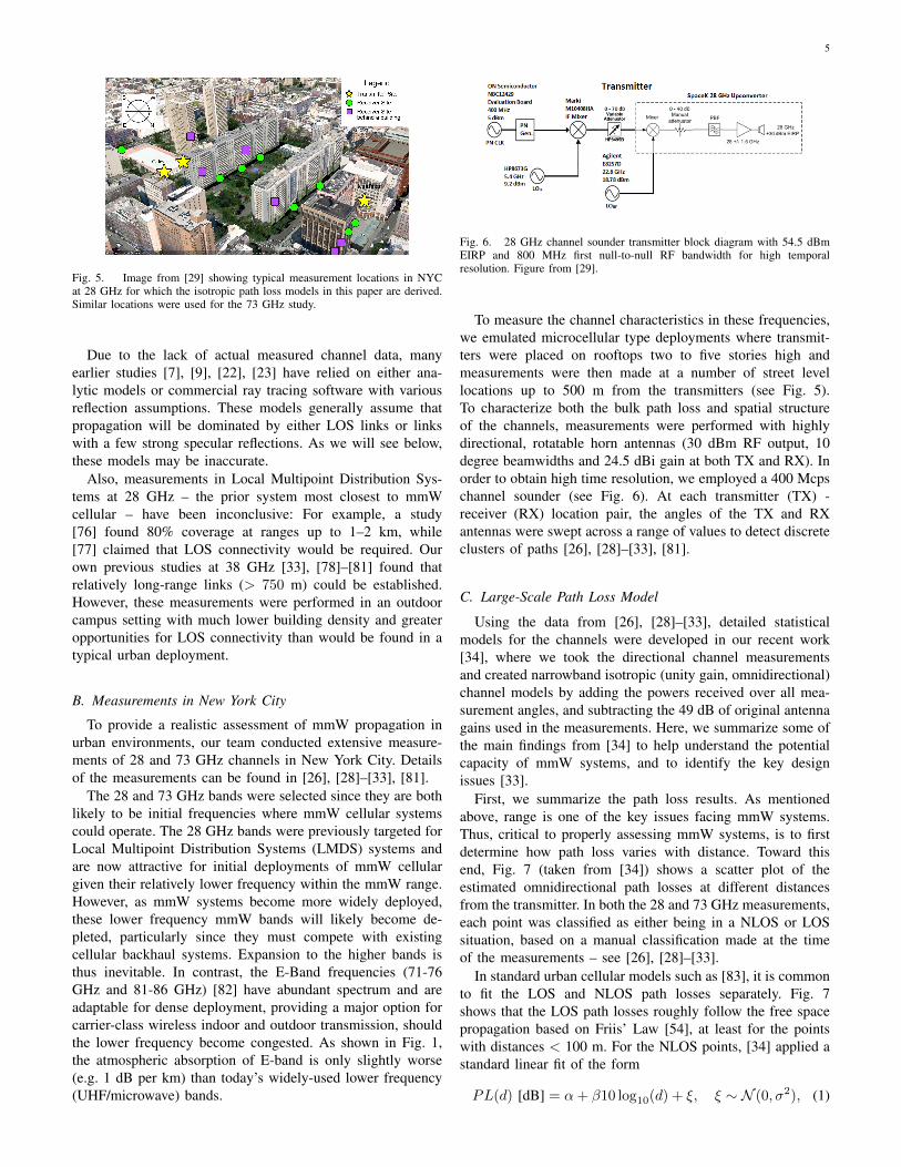
Fig. 5. Image from [29] showing typical measurement locations in NYCat 28 GHz for which the isotropic path loss models in this paper are derived.Similar locations were used for the 73 GHz study.
Due to the lack of actual measured channel data, manyearlier studies [7], [9], [22], [23] have relied on either ana-lytic models or commercial ray tracing software with variousreflection assumptions. These models generally assume thatpropagation will be dominated by either LOS links or linkswith a few strong specular reflections. As we will see below,these models may be inaccurate.
Also, measurements in Local Multipoint Distribution Sys-tems at 28 GHz – the prior system most closest to mmWcellular – have been inconclusive: For example, a study[76] found 80% coverage at ranges up to 1–2 km, while[77] claimed that LOS connectivity would be required. Ourown previous studies at 38 GHz [33], [78]–[81] found thatrelatively long-range links (> 750 m) could be established.However, these measurements were performed in an outdoorcampus setting with much lower building density and greateropportunities for LOS connectivity than would be found in atypical urban deployment.
B. Measurements in New York City
To provide a realistic assessment of mmW propagation inurban environments, our team conducted extensive measure-ments of 28 and 73 GHz channels in New York City. Detailsof the measurements can be found in [26], [28]–[33], [81].
The 28 and 73 GHz bands were selected since they are bothlikely to be initial frequencies where mmW cellular systemscould operate. The 28 GHz bands were previously targeted forLocal Multipoint Distribution Systems (LMDS) systems andare now attractive for initial deployments of mmW cellulargiven their relatively lower frequency within the mmW range.However, as mmW systems become more widely deployed,these lower frequency mmW bands will likely become de-pleted, particularly since they must compete with existingcellular backhaul systems. Expansion to the higher bands isthus inevitable. In contrast, the E-Band frequencies (71-76GHz and 81-86 GHz) [82] have abundant spectrum and areadaptable for dense deployment, providing a major option forcarrier-class wireless indoor and outdoor transmission, shouldthe lower frequency become congested. As shown in Fig. 1,the atmospheric absorption of E-band is only slightly worse(e.g. 1 dB per km) than today’s widely-used lower frequency(UHF/microwave) bands.
Fig. 6. 28 GHz channel sounder transmitter block diagram with 54.5 dBmEIRP and 800 MHz first null-to-null RF bandwidth for high temporalresolution. Figure from [29].
To measure the channel characteristics in these frequencies,we emulated microcellular type deployments where transmit-ters were placed on rooftops two to five stories high andmeasurements were then made at a number of street levellocations up to 500 m from the transmitters (see Fig. 5).To characterize both the bulk path loss and spatial structureof the channels, measurements were performed with highlydirectional, rotatable horn antennas (30 dBm RF output, 10degree beamwidths and 24.5 dBi gain at both TX and RX). Inorder to obtain high time resolution, we employed a 400 Mcpschannel sounder (see Fig. 6). At each transmitter (TX) -receiver (RX) location pair, the angles of the TX and RXantennas were swept across a range of values to detect discreteclusters of paths [26], [28]–[33], [81].
C. Large-Scale Path Loss Model
Using the data from [26], [28]–[33], detailed statisticalmodels for the channels were developed in our recent work[34], where we took the directional channel measurementsand created narrowband isotropic (unity gain, omnidirectional)channel models by adding the powers received over all mea-surement angles, and subtracting the 49 dB of original antennagains used in the measurements. Here, we summarize some ofthe main findings from [34] to help understand the potentialcapacity of mmW systems, and to identify the key designissues [33].
First, we summarize the path loss results. As mentionedabove, range is one of the key issues facing mmW systems.Thus, critical to properly assessing mmW systems, is to firstdetermine how path loss varies with distance. Toward thisend, Fig. 7 (taken from [34]) shows a scatter plot of theestimated omnidirectional path losses at different distancesfrom the transmitter. In both the 28 and 73 GHz measurements,each point was classified as either being in a NLOS or LOSsituation, based on a manual classification made at the timeof the measurements – see [26], [28]–[33].
In standard urban cellular models such as [83], it is commonto fit the LOS and NLOS path losses separately. Fig. 7shows that the LOS path losses roughly follow the free spacepropagation based on Friis’ Law [54], at least for the pointswith distances < 100 m. For the NLOS points, [34] applied astandard linear fit of the form
PL(d) [dB] = α+ β10 log10(d) + ξ, ξ ∼ N (0, σ2), (1)

6
Fig. 7. Scatter plot along with a linear fit of the estimated omnidirectionalpath losses as a function of the TX-RX separation for 28 and 73 GHz. Figurefrom [34] based on the NYC data in [26].
where d is the distance in meters, α is the best (MMSE)fit floating intercept point over the measured distances (30to 200 m) [81], β is the slope of the best fit, and σ2 thelognormal shadowing variance. The parameter values for α, βand σ are shown in Table I along with other parameters thatare discussed below.
Note that a close-in free space reference path loss modelwith a fixed leverage point may also be used, which isequivalent to (1) with the constraint that α + β10 log10(d0)has some fixed value PL(d0) for some close-in free spacereference distance d0. Work in [81] shows that this close-infree space model is less sensitive to perturbations in data andhas valuable insights based on propagation physics for theslope parameter β (e.g. β = 2 is free space propagation andβ = 4 is the asymptotic path loss exponent for a two-raymodel). The close-in free space reference model has only aslightly greater (e.g. 0.5 dB larger standard deviation) fittingerror. While the analysis below will not use this fixed leveragepoint, we point this out to caution against ascribing anyphysical meaning to the estimated values for α or β in (1)when a floating intercept is used.
We can compare the experimentally-derived model (1) forthe mmW frequencies with those used in conventional cellularsystems. To this end, Fig. 8 plots the median omnidirectionalpath loss for the following models:• Empirical NYC: These curves are the based on the om-
nidirectional path loss predicted by our linear model (1)for the mmW channel with the parameters from Table I,as derived from the directional measurements in [26].
• Free space: The theoretical free space path loss is givenby Friis’ Law [54]. We see, for example, that at d =100 m, the free space path loss is approximately 30 dBless than the omnidirectional propagation model we havedeveloped here based on the directional measurements in[26]. Thus, many of the works such as [9], [22], [23]that assume free space propagation may be somewhatoptimistic in their capacity predictions. Also, it is inter-
Fig. 8. Comparison of distance-based path loss models with unity gain anten-nas from [34]. The curves labeled “Empirical NYC” are the experimentally-derived mmW models based on the NYC data [26]. These are compared tofree space propagation for the same frequencies and the 3GPP Urban Micro(UMi) model [83] for 2.5 GHz.
esting to point out that one of the models assumed in [7](PLF1) is precisely free space propagation + 20 dB – acorrection factor that is 5 to 10 dB more optimistic thanour experimental findings.
• 3GPP UMi: The standard 3GPP urban micro (UMi) pathloss model with hexagonal deployments [83] is given by
PL(d) [dB] = 22.7 + 36.7 log10(d) + 26 log10(fc), (2)
where d is distance in meters and fc is the carrierfrequency in GHz. Fig. 8 plots this path loss model atfc = 2.5 GHz. We see that our propagation modelsfor unity gain antennas at both 28 and 73 GHz predictomnidirectional path losses that, for most of the distances,are approximately 20 to 25 dB higher than the 3GPP UMimodel at 2.5 GHz. However, the wavelengths at 28 and73 GHz are approximately 10 to 30 times smaller than at2.5 GHz. Since, for a fixed antenna area, the beamforminggain grows with λ−2, the increase in path loss can beentirely compensated by applying beamforming at eitherthe transmitter or receiver. In fact, the path loss canbe more than compensated relative to today’s cellularsystems, with beamforming applied at both ends. Weconclude that, barring outage events and maintaining thesame physical antenna size, mmW propagation does notlead to any reduction in path loss relative to currentcellular frequencies and, in fact, may be improved overtoday’s systems. Moreover, further gains may be possiblevia spatial multiplexing as we will see below.
D. Angular and Delay Spread Characteristics
The channel sounding system, with 10 degree beamwidthrotatable horn antennas and 400 MHz baseband signal band-width, enables high resolution time and angular spread mea-surements. One of the key, and surprising, findings of ourstudies, was the presence of several distinct clusters of pathswith significant angular and delay spread between the clusters.This observation provides strong evidence that – at least

7
TABLE IKEY EXPERIMENTALLY-DERIVED MODEL PARAMETERS USED HERE AND [34] BASED ON THE NYC DATA IN [26].
Variable Model Model Parameter Values
28 GHz 73 GHz
Omnidirectional path loss, PL PL = α+ 10β log10(d) + ξ, d in meters α = 72.0, β = 2.92 α = 86.6, β = 2.45
Lognormal shadowing, ξ ξ ∼ N (0, σ2) σ = 8.7 dB σ = 8.0 dB
Number of clusters, K K ∼ max{Poisson(λ), 1} λ = 1.8 λ = 1.9
Cluster power fraction See (3). rτ = 2.8, ζ = 4.0 rτ = 3.0, ζ = 4.0
BS cluster rms angular spread σ is exponentially distributed, E(σ) = λ−1 Horiz λ−1 = 10.2◦;Vert λ−1 = 0◦ (*)
Horiz λ−1 = 10.5◦;Vert λ−1 = 0◦ (*)
UE rms angular spread σ is exponentially distributed, E(σ) = λ−1 Horiz λ−1 = 15.5◦;Vert λ−1 = 6.0◦
Horiz λ−1 = 15.4◦;Vert λ−1 = 3.5◦
Note: The model parameters are derived in [34] based on converting the directional measurements from the NYC data in [26], and assuming anisotropic (omnidirectional, unity gain) channel model with the 49 dB of antenna gains removed from the measurements.(*) BS downtilt was fixed at 10 degree for all measurements, resulting in no measurable vertical angular spread at BS.
Fig. 9. Top: AoA power profile measured in the courtyard outside a typicalbuilding in the 28 GHz measurement campaign. Bottom: Power delay profileat a different location. Figures from [31] and [55].
with the microcellular type antennas in an urban canyon-typeenvironment – mmW signals appear to propagate via severalNLOS paths rather than a small number of LOS links. Wenote that these NLOS paths are arriving via reflections andscattering from different buildings and surfaces [26], [28]–[33], [78].
To illustrate the presence of multiple path clusters, thetop panel of Fig. 9 shows the measured angular-of-arrival(AoA) power profile at a typical location in our 28 GHz
measurements. At this location, we clearly see three angularclusters or “lobes” [31] – a common number observed overall locations. Similarly, the bottom panel shows the powerdelay profile and we see that several clusters are apparent.The presence of discrete clusters, each with relatively narrowangular and delay spread, will have certain implications forthe receiver design that we discuss below in Section V-E.
The paper [34] provides a detailed analysis of the statisticalproperties of the paths clusters as based on the data [26], [28]–[33]. Some of the findings are as follows:• The number of clusters is well-modeled as a Poisson
random variable with an average of approximately twoclusters at each location. Due to the presence of mul-tiple clusters and angular spread within clusters, manylocations exhibit sufficient spatial diversity to supportpotentially two or even three spatial degrees of freedom.See [34] for more details.
• The angular spread (both between clusters and withinclusters) occurs in the azimuth (horizontal) directions atboth the transmitter and receiver, indicating the presenceof local scattering at both ends. Some vertical (elevation)angular spread is also observed at the receivers on thestreet, potentially from ground reflections. The root-mean-square (rms) beamspread within each cluster canvary significantly and is well-modeled via an exponentialdistribution with similar parameters as current cellularmodels such as [83].
• The distribution of power amongst the path clusters arewell-modeled via a 3GPP model [83] where the fractionof powers in the K clusters are modeled as randomvariables γ1, . . . , γK with
γk =γ′k∑Kj=1 γ
′j
, γ′k = Urτ−1k 10−0.1Zk , (3)
where the first random variable, Uk ∼ U [0, 1], is uni-formly distributed and accounts for variations in delaybetween the clusters (clusters arriving with higher delaytend to have less power), and the second random variable,Zk ∼ N (0, ζ2), is Gaussian and accounts for lognormal

8
variations due to difference in shadowing on differentclusters. The variables rτ and ζ are constants fit to theobserved power fractions. After fitting the parameters tothe data, we found the main cluster does not have theoverwhelming majority of power. Significant power isoften found in the second or even third strongest clusters,even considering attenuation due to longer propagationdelay [34], again indicating the possibility of spatialmultiplexing gains between a single base station and UE.
E. Outage Probability
Due to the fact that mmW signals cannot penetrate manyoutdoor building walls, but are able to reflect and scatter off ofthem, signal reception in urban environments relies on eitherLOS links or strong reflections and scattering from buildingand ground surfaces. Therefore, a key risk in mmW cellular isoutage caused by shadowing when no reflective or scatteringpaths can be found [31], [32].
To assess this outage probability, the study [34] used datafrom [26], [28]–[33] which attempted to find signals of suit-able strength at a number of locations up to 500 m from thetransmitter. Interestingly, the analysis showed that signals weredetectable at all 30 locations in Manhattan within 175 m fromthe cell. However, at locations at distances greater than 175 m,most locations experienced a signal outage. Since outage ishighly environmentally dependent, one cannot generalize toomuch from these measurements. Actual outage may be moresignificant if there were more local obstacles, if a humanwere holding the receiver in a handheld device or, of course,if mobiles were indoor. We discuss some of these potentialoutage effects below.
IV. CAPACITY EVALUATION AND LESSONS LEARNED
Using the experimentally-derived channel models from theNYC data [26], the paper [34] provided some simple systemsimulations to assess the potential urban mmW cellular sys-tems. We summarize some of the key findings in that workalong with other studies to estimate the possible capacity ofmmW systems and identify the main design issues.
A. System Model
Our work here and [34] follows a standard cellular eval-uation methodology [83] where the base stations (BSs) anduser equipments (UEs) are randomly placed according to somestatistical model and the performance metrics were then mea-sured over a number of random realizations of the network.Since the interest is in small cell networks, we followed aBS and UE distribution similar to the 3GPP Urban Micro(UMi) model in [83] with some parameters taken from [7],[8]. The specific parameters are shown in Table II. Observethat we have assumed an inter-site distance (ISD) of 200 m,corresponding to a cell radius of 100 m. Also, the maximumtransmit powers of 20 dBm at the UE and 30 dBm at the BSwere taken from [7], [8]. These transmit powers are reasonablesince current CMOS RF power amplifiers in the mmW rangeexhibit peak efficiencies of at least 8 to 20% [6], [84], [85].
TABLE IIDEFAULT NETWORK PARAMETERS FROM [34].
Parameter Description
BS layout and sectorization Hexagonally arranged cell sites placedin a 2km x 2km square area withthree cells per site.
UE layout Uniformly dropped in area withaverage of 10 UEs per BS cell (i.e. 30UEs per cell site).
Inter-site distance (ISD) 200 m
Carrier frequency 28 and 73 GHz
Duplex mode TDD
Transmit power 20 dBm (uplink), 30 dBm (downlink)
Noise figure 5 dB (BS), 7 dB (UE)
BS antenna 8x8 λ/2 uniform linear array
UE antenna 4x4 λ/2 uniform linear array for28 GHz and 8x8 array for 73 GHz.
Beamforming Long-term beamforming withoutsingle-user or multi-user spatialmultiplexing
We considered a network exclusively with mmW cells. Ofcourse, in reality, mmW systems will be deployed with anoverlay of conventional larger UHF / microwave cells. Thus,an actual mmW heterogeneous network will have a highercapacity, particularly in terms of cell edge rates. We discusssome of these issues in Section V-F.
To model the beamforming – which is essential in mmWsystems – we followed a conservative model, making thesimplifying assumption that only single stream processing (i.e.no single-user or multi-user spatial multiplexing) was used.Of course, inter-cell coordinated beamforming and multiple-input multiple-output (MIMO) spatial multiplexing [23], [86]may offer further gains, particularly for mobiles close to thecell. Although these gains are not considered here, following[55], we considered multi-beam combining that can captureenergy from optimally non-coherently combining multiplespatial directions to obtain capacity results here and in [34].However, we only considered long-term beamforming [87] toavoid tracking of small-scale fading, which may be slightlychallenging at very high Doppler frequencies (e.g. bullettrains) at mmW.
Both downlink and uplink assumed proportional fairscheduling with full buffer traffic. In the uplink, it is importantto recognize that different multiple access schemes result indifferent capacities. If the BS allows one UE to transmitfor a portion of time in the whole band, the total receivepower will be limited to that offered by a single user. Ifmultiple UEs are allowed to transmit at the same time timebut on different subbands, then the total receive power willbe greater, which is advantageous for users that are notbandwidth-limited. The simulations below thus assume thatsubband FDMA is possible. As we discuss in Section V-B,this enables much greater capacity as well as other benefitsat the MAC layer. However, realizing such multiple accesssystems presents certain challenges in the baseband front-endwhich are also discussed.

9
B. SINR and Rate Distributions
We plot SINR and rate distributions in Fig. 10 and Fig.11 respectively. The distributions are plotted for both 28 and73 GHz and for 4x4 and 8x8 arrays at the UE. The BS antennaarray is held at 8x8 for all cases, although we expect futuremmW base stations to have thousands of antenna elementleading much greater gains and directionality. Some of thekey statistics are listed in Table III. More details can be foundin [34].
There are two immediate conclusions we can draw fromthe curves. First, based on this evaluation, the sheer capacityof a potential mmW system is enormous. Cell capacities areoften greater than 1 Gbps and the users with the lowest 5%cell edge rates experience greater than 10 Mbps. These rateswould likely satisfy many of the envisioned requirements forBeyond 4G systems such as [5], [66].
Second, for the same number of antenna elements, the ratesfor 73 GHz are approximately half the rates for the 28 GHz.However, a 4x4 λ/2-array at 28 GHz would take about thesame area as an 8x8 λ/2 array at 73 GHz. Both would beroughly 1.5× 1.5 cm2, which could be easily accommodatedin a handheld mobile device. In addition, we see that 73 GHz8x8 rate and SNR distributions are very close to the 28 GHz4x4 distributions, which is reasonable since we are keepingthe UE antenna size approximately constant. Thus, we canconclude that the loss from going to the higher frequencies canbe made up from larger numbers of antenna elements withoutincreasing the physical antenna area.
C. Comparison to 4G Capacity
We can compare the SINR distributions in Fig. 10 tothose of a traditional cellular network. Although the SINRdistribution for a cellular network in a traditional UHF ormicrowave band is not plotted here, the SINR distributionsin Fig. 10 are actually slightly better than those found incellular evaluation studies [83]. For example, in Fig. 10, onlyabout 10% of the mobiles appear under 0 dB, which is alower fraction than typical cellular deployments. We concludethat, although mmW systems have an omnidirectional pathloss that is 20 to 25 dB worse than conventional microwavefrequencies, short cell radii combined with highly directionalbeams are able to completely compensate for the loss, and, infact, improve upon today’s systems.
We can also compare the capacity and cell edge rates usingthe numbers in Table III. The LTE capacity numbers are takenfrom the average of industry reported evaluations given in [83]– specifically Table 10.1.1.1-1 for the downlink and Table1.1.1.3-1 for the uplink. The LTE evaluations include advancedtechniques such as spatial division multiple access (SDMA),although not coordinated multipoint. For the mmW capacity,we assumed 50-50 uplink-downlink (UL-DL) TDD split anda 20% control overhead in both the UL and DL directions.
Under these assumptions, we see from Table III that thespectral efficiency of the mmW system for either the 28 GHz4x4 array or 73 GHz 8x8 array is roughly comparable to
Fig. 10. Downlink (top plot) / uplink (bottom plot) SINR CDF at 28 and73 GHz with 4x4 and 8x8 antenna arrays at the UE. The BS antenna arrayis held at 8x8. Figure from [34] based on measurement data in [26].
state-of-the art LTE systems2. Due to its larger bandwidth,we see in Table III (cell capacity) that mmW systems offer asignificant 20-fold increase of overall cell capacity. Moreover,this is a basic mmW system with no spatial multiplexingor other advanced techniques – we expect even higher gainswhen advanced technologies are applied to optimize the mmWsystem.
While the 5% cell edge rates are less dramatic, they stilloffer a 9 to 10 fold increase. This indicates a significantlimitation of mmW systems under NLOS propagation – edgeof cell users become power-limited and are unable to fullyexploit the increased spectrum. Thus, other features, such asthe use of repeaters / relays, will be needed achieve a moreuniform performance in mmW systems in these scenarios.
D. Interference vs. Thermal Noise
A hallmark of current small cell systems in urban environ-ments is that they are overwhelmingly interference-limited,with the rate being limited by bandwidth, and not power.Our studies reveal that mmW small cell systems representa departure from this model. For example, Fig. 12 plots the
2Note that the spectral efficiency for the mmW system is quoted includingthe 20% overhead, but not the 50% UL-DL duplexing loss. Hence, the cellcapacity in Table III is C = 0.5ρW , where ρ is the spectral efficiency andW is the baseband bandwidth.

10
TABLE IIICONSERVATIVE MMW AND LTE CELL CAPACITY/CELL EDGE RATE COMPARISON FROM [34] BASED ON ISOTROPIC CHANNEL MODELS DERIVED FROM
MEASUREMENT DATA IN [26].
System BW &Duplex
BSantenna
UEantenna
fc(GHz)
Spec. eff (bps/Hz) Cell capacity (Mbps) 5% Cell edge rate (Mbps)
DL UL DL UL DL UL
mmW 1 GHzTDD
8x8 4x4 28 2.25 2.38 1130 1190 17.4 21.6
8x8 8x8 28 2.83 2.84 1420 1420 32.7 36.3
8x8 4x4 73 1.45 1.65 730 830 6.6 9.6
8x8 8x8 73 2.15 2.31 1080 1160 16.6 22.1
LTE 20+20MHz FDD
2 TX,4 RX
2 2.5 2.69 2.36 53.8 47.2 1.80 1.94
Note 1. Assumes 20% overhead and 50% UL-DL duty cycle for the mmW systemNote 2. Long-term, non-coherent beamforming are assumed at both the BS and UE in the mmW system. However, the mmW results assumeno spatial multiplexing gains, whereas the LTE results from [83] include spatial multiplexing and beamforming.
Fig. 11. Downlink (top plot) / uplink (bottom plot) rate CDF at 28 and73 GHz with 4x4 and 8x8 antenna arrays at the UE. The BS antenna arrayis held at 8x8. Figure from [34] based on measurement data in [26].
distribution of the interference-to-thermal noise (INR) for boththe uplink and downlink in our simulation of the mmW systemat 28 GHz. We see that interference is not dominant. In fact,for the majority of mobiles, thermal noise is comparable oreven larger, particularly in the downlink.
At the same time, although interference is not dominant,many of the mobiles are in a bandwidth-limited, rather thanpower-limited regime. For example, Table III shows that theaverage spectral efficiency is approximately 2.1 to 2.4 bps/Hz
Fig. 12. Interference-to-noise ratio in the uplink and downlink for the 28 GHzwith a 4x4 UE antenna array.
in the uplink and downlink for 4x4 28 GHz or 8x8 73 GHzsystems. We find from Table III that, if spatial multiplexingis not exploited, links will be bandwidth-limited and notpower-limited, even though interference is not dominant. Weconclude that, without spatial multiplexing, mmW systemswould represent a new network operating point not seen incurrent urban cellular deployments: large numbers of mobileswould experience relatively high SINR in directionally isolatedlinks. In a sense, mmW takes us “back to the future” whencellular was first deployed in virgin spectrum.
Of course, without exploiting spatial multiplexing systemswould not benefit from all the degrees of freedom. We have notyet evaluated single or multi-user MIMO, but such techniqueswould lower the SINR per stream for the higher SINR mobiles.However, the INR distribution would not significantly changesince the total transmit power would be constant. Therefore,the links would remain limited by thermal noise rather thaninterference.
E. Effects of Outage
As mentioned above, one of the significant risks of mmWsystems is the presence of outage – the fact that there is a

11
non-zero probability that the signal from a given base stationcan be too weak to be detectable.
To quantify this effect, the paper [34] estimated the capacityunder various outage probability models. The simulationsabove assumed that at distances greater than a threshold ofT = 175m, the signal would not be detectable and hence thelink would be in outage. This assumption was based on thedata we observed in [26], [28]–[33]. However, as discussed inSection III-E, mobiles in other environments may experienceoutages closer to the cell, particularly if there is a lot of groundclutter or the humans themselves blocking the signal. To modelthis scenario, the paper [34] considered a hypothetical outagemodel, loosely based on [83], where there was a significantoutage probability even close to the cell. For example, in thismodel (called a “soft outage” for reasons explained in [34]),there was approximately a 20% probability that a link to a cellwould be in outage even when it was only 80 m from the cell.
Interestingly, under this more conservative outage model,the average cell capacity was not significantly reduced. How-ever, both the uplink and downlink 5% cell edge rates fell bya dramatic 50%. This reduction shows that mmW systems arerobust enough that mobiles in outage to any one cell will stillbe able to establish a connection to another cell. On the otherhand, in environments where the outages close to the cell arefrequent, the gains of mmW systems will not be nearly asuniform, with cell edge users suffering significantly.
F. Other Studies
Although our study here and in [34] was the first to usethe experimentally-derived omnidirectional channel modelsfrom the directional data in [26], the results in [34] roughlycorroborate the findings of very high capacity from mmWsystems predicted in several earlier analyses: For example,the study in [7] estimated approximately 300 Mbps per cellthroughput in a 500 MHz system. This capacity correspondsto a somewhat lower spectral efficiency than what we showhere and in [34], but the study in [7] assumed only minimalbeamforming at the receiver (either no beamforming or a 2x2array) and a much larger cell radius of 250 m.
In [9], ray tracing software is used to analyze a mmW cam-pus network and a median total system capacity of 32 Gbpswith five cell sites, each cell site having four cells, is found.Since the bandwidth in that study was 2 GHz, the spectralefficiency was approximately 32/5/4/2 = 0.8 bps/Hz/cell.This number again is lower than our predictions, but [9]was limited to QPSK modulation. Somewhat higher capacitynumbers were found in a follow up study [65] in both campusand urban environments. A later study presented in [66]predicted average spectral efficiencies of almost 1.5 bps/Hz ina 2 GHz system in an urban grid deployment, a number onlyslightly lower than our value of 2.3 to 2.8 bps/Hz. In all thesestudies, the cell edge rates compare similarly to the predictedvalues in [34], assuming one normalizes to the number of usersin each cell.
In a different work, [22] used a stochastic geometry analysisand predicted almost 5.4 bps/Hz, which is almost twice ourestimated spectral efficiency. However, that work assumed that
all links can operate at the Shannon limit with no maximumspectral efficiency.
This comparison illustrates that, in a number of differentscenarios and analysis methods, the absolute spectral effi-ciency and cell edge rate numbers are roughly comparablewith estimates here and in [34] that used experimentally-derived channel models. Thus, the broad message remainsthe same: under a wide variety of simulation assumptions,mmW systems can offer orders of magnitude increases incapacity and cell edge rate over state-of-the-art systems incurrent cellular bands.
V. KEY DESIGN ISSUES AND DIRECTIONS FOR MMW 5GThe above preliminary results show that while mmW bands
offer tremendous potential for capacity, cellular systems mayneed to be significantly redesigned. In this section, we identifyseveral key design issues that need to be addressed from asystems perspective if the full gains of mmW cellular systemsare to be achieved.
A. Directional Transmissions and Broadcast Signaling
The most obvious implication of the above results is thatthe gains of mmW system depend on highly directional trans-missions. As we discussed above, directionality gains withappropriate beamforming can completely compensate for, andeven further reduce, any increase in the omnidirectional pathloss with frequency. Indeed, once we account for directionalgains enabled by smaller wavelengths, the path loss, SNR andrate distributions in the mmW range compare favorably with(and may improve upon) those in current cellular frequencies.
One particular challenge for relying on highly directionaltransmissions in cellular systems is the design of the synchro-nization and broadcast signals used in the initial cell search.Both base stations and mobiles may need to scan over a rangeof angles before these signals can be detected. This “spatialsearching” may delay base station detection in handovers —a point made in a recent paper [88]. Moreover, even after amobile has detected a base station, detection of initial randomaccess signals from the mobile may be delayed since the basestation may need to be aligned in the correct direction.
A related issue is supporting intermittent communication(say through discontinuous reception and transmission (DRXand DTX) modes) which has been essential in standardssuch as LTE for providing low power consumption with“always on” connectivity [89]. In order that either a mobileor base station can quickly begin transmitting, channel stateinformation in the form of the spatial directions will needto be maintained at the transmitter. If cells are small, eventhe second-order spatial statistics of the channel may changerelatively fast implying some sort of intermittent transmissionsmay need to be performed to track the channel state.
B. Multiple Access and Front-End / Baseband Considerations
With small cells, the need for future spectrum / bandwidthflexibility, support for beamforming and low cost, TDD (timedivision duplex) is an attractive duplexing strategy for mmW.Our analysis in Table III assumes TDD for mmW.

12
UE1 UE2 UE1 UE2
TDMA only TDMA and FDMA
TTI
Fig. 13. Multiple access: Enabling FDMA (within a TDD time slot),where multiple UEs can be scheduled at a time, can offer numerous benefitsin mmW systems including improved power in the uplink, more efficienttransmission of small packets and reduced UE power consumption. A keydesign issue is how to support FDMA in TDD with mmW front-ends thatperform beamsteering in analog.
Fig. 14. Power loss with TDMA only: Designs that do not enable multipleusers to be scheduled at the same time can suffer a significant penaltyin capacity in the uplink due to loss of power. Shown here is the ratedistribution comparing FDMA and TDMA scheduling using beamformingwith the 28 GHz isotropic channel model.
However, closely related to the issue of directional trans-missions is how to support frequency-division multiple accesswithin the TDD time slots. Current cellular systems use digitalprocessing for MIMO and beamforming. However, with thelarge numbers of antennas and wide bandwidths, it is simplynot practical from a power or cost perspective to place high-resolution, wideband ADCs on each antenna element in themmW range [6]–[8]. Most commercial designs have thus as-sumed phased-array architectures where signals are combinedeither in free space or RF with phase shifters [90]–[92] orat IF [93]–[95] prior to the A/D conversion. A limitation ofsuch architectures is that they will forgo the support of spatialmultiplexing and multi-user transmissions within the TDDtime slots and require time-division multiple access (TDMA)with only one user within a time slot being scheduled at atime. In particular, FDMA transmissions within the same timeslot as supported in LTE through resource blocks will not bepossible – See Fig. 13.
Enabling granular allocations in frequency is one of themain hallmarks of LTE, and sacrificing this capability byrestricting to TDMA scheduling will bear significant costs inmmW:
• Uplink power: Restricting to TDMA scheduling within aTDD time slot implies that the power of only UE can bereceived at a time. Since mobiles at the cell edge may bepower-limited, this reduction of power can significantlyreduce capacity. For example, according to the uplink rateCDF shown in Fig. 14, one can easily see an order ofmagnitude improvement when multi-user transmission isenabled by FDMA, compared to a baseline TDMA, bothassuming TDD.
• Support for small packets: Supporting multi-user trans-missions will also be essential to efficiently support mes-sages with small payloads and is needed for low latencymachine-to-machine communications [96]. Specifically,when only one UE can transmit or receive at a time,it must be allocated the entire bandwidth in a TDDslot, which is extremely wasteful for small packets. Asan example, in the design of [8], the transmission timeinterval (TTI) is 125µs. Thus, a 1 GHz allocation at thisTTI will have approximately 125,000 degrees of freedom.Such large transport blocks would be terribly inefficient,for example, for TCP ACKs as well as other controlsignaling.
• Power consumption: From a power consumption perspec-tive, it may be preferable for individual UEs to onlyprocess only a smaller portion (say 100 MHz) of the bandduring a time slot. Such subband allocations can reducethe power consumption of the baseband processing whichgenerally scales linearly in the bandwidth.
Thus, a key design issue facing 5G mmW systems ishow to support multiple access while enabling low powerconsumption, particularly at the UE. One promising route hasbeen the use of compressed sensing and other advanced low-bit rate technologies, suggested in [97].
In addition, one may consider other SDMA algorithms thatoptimally exploit a smaller number of beams. For example,each UE can still support only one digital stream, potentiallyon a subband for low power consumption. The base station,which would generally have somewhat higher power capacity,could support a smaller number, say K, beams. Then, tosupport N UEs with K < N , the base station can simplyselect the K beams to span the “best” K-dimensional subspaceto capture the most energy of the N users.
C. Directional Relaying and Dynamic DuplexingAnother key design issue for mmW cellular systems is
support for repeaters / relays – a feature that can be particularlyvaluable due to the need for range extension. In currentcellular systems, relaying has been primarily used both forcoverage extension and, to a lesser extent, capacity expan-sion when backhaul is not available [99]–[101]. Althoughsignificant research went into enabling relaying in 3GPP LTE-Advanced [102], the projected gains have been modest. Indense interference-limited environments, the loss in degreesof freedom with half-duplex constraints and multiple trans-missions is typically not worth the increase in received powerfrom shorter range.
With regards to relaying, mmW networks may be fundamen-tally different. As discussed above, one of the most greatest

13
Subframe(~ 1ms)
Link contention & scheduling period
Data transmission period
(a) Directional relaying (b) Synchronous frame structure for peer-to-peer communication
Fig. 15. Directional mmW relaying: (a) Multihop directional relayingcan provide wireless backhaul and extend coverage of mmW signals in thepresence of clutter and shadowing. (b) A synchronous peer-to-peer framestructure along the lines of [98] can enable fast coordination and resourceallocation across relays, base stations and mobiles with dynamic duplexing.
challenges for mmW systems is that mobiles may be in outageto the closest cell, dramatically reducing the cell edge rate. Inthese cases, relaying may be necessary to selectively extendcoverage to certain users and provide a more uniform qualityof service throughout the network. Furthermore, given theinability of mmW signals to penetrate indoors, relaying wouldalso be essential to provide seamless indoor-outdoor coverageand coverage in and around vehicles, airplanes, etc. Relayingmay also be valuable for backhaul to picocells when fiberconnectivity is not available [37]–[39]. Depending on the celllocations, some of these mmW links may be in the clutter andrequire NLOS connectivity similar to the access links – See,for example, Fig. 15(a).
In order to obtain the full advantages of relaying, cellularsystems may need to be significantly re-designed. Cellularsystems have traditionally followed a basic paradigm dividingnetworks into distinct base stations and mobiles, with relaystypically being added as an afterthought. However, given thecentral role that relaying may play in the mmW range for boththe access link and for backhaul, it may be worth investigat-ing new peer-to-peer topologies, such as Qualcomm’s Flash-LinQ system [98], where there is less centralized schedulingand where frequency band and time slots are not staticallypre-allocated to traffic in any one direction. As shown inFig. 15(b), one may consider symmetric frame structures thatare common in the uplink and downlink. The directions of thelinks would not necessarily need to be synchronized acrossthe network, and a periodic contention period can be used toreassign the directions of the links as necessary. Such a designwould be a significant departure from the uplink-downlink incurrent LTE systems, but would enable much greater flexibilityfor multihop networks and integrated systems for both accessand backhaul.
D. An End to Interference?
As mentioned above, current cellular networks in denseurban deployments are overwhelmingly interference-limited.At a high level, mitigating this interference can be seen asthe driving motiviation behind many of the advanced tech-nologies introduced into cellular systems in the last decade.These techniques include coordinated multipoint, inter-cellular
interference coordination and more forward-looking conceptssuch as interference alignment.
One of the striking conclusions of the above analysis isthat many of these techniques may have much more limitedgains in the mmW space. As we saw, for many mobiles,thermal noise is significantly larger than interference. Thatis, in mmW systems with appropriate beamforming, linksbecome directionally isolated and inter-cellular interference isgreatly reduced. This fact implies that point-to-point, ratherthan network, technologies may play a much larger role inachieving capacity gains in these systems.
E. Exploiting Channel Sparsity and Compressed Sensing
As described in Section II-B, one possible challenge inmmW system is the high Doppler. In general, Doppler spreadis a function of the total angular dispersion, carrier frequencyand mobile velocity [54]. Thus, due to the high carrier fre-quencies and significant local scattering, one might initiallythink that the total Doppler spread in mmW systems will behigh and potentially difficult to track.
However, the measurements reviewed in Section III revealedthat signals generally arrive on a small number of path clusters,each with relatively small angular spread. Directional antennaswill further reduce the multipath angular spread [103]. Thisproperty implies that the individually resolvable multipathcomponents will vary very slowly – a fact confirmed directlyin our experiments in [26]. This is good news.
To understand how to exploit these slow variations fortracking the channel, first observe that the narrowband channelresponse at any particular frequency could be described as
h(t) =
K∑k=1
gk(t)e2πifd cos(θk)t, (4)
where K is the number of clusters, fd is the maximum Dopplershift, θk is the central angle of arrival of the cluster and gk(t)is the time-varying gain of the channel related to the angularspread within the cluster. Since the angular spread within eachcluster is small, the cluster gains gk(t) will generally be slowlyvarying even though the aggregate channel h(t) may havemuch higher variations. Moreover, the angles of arrival θkare also typically slowly varying since they are a result ofthe large scale scattering environment and do not change withsmall scale mobility. This fact suggests that even though h(t)may change rapidly, the parametrization (4) may enable moreaccurate tracking, particularly since the number of clusters, K,tends to be small (K is typically 1 to 5 in our measurements).
The parametrization (4) is fundamentally nonlinear andanalogous to the types of models used in finite rate of in-novation models [104] and compressed sensing-based channelestimation and channel sounding [105]–[108]. The extensionof these methods to very wideband systems with large numbersof antennas may therefore have significant value.
F. Heterogeneous Networking Issues
As described in Section II-C, mmW systems cannot bedeployed in a standalone manner. To provide uniform, reliable

14
coverage, fallback to cellular systems in conventional UHFor microwave frequencies will be necessary. While supportfor heterogeneous networks has been a key design goal inrecent cellular standards, mmW systems will push the need forsupport for heterogeneous networks in several new directions.
Most importantly, the heterogeneous network support inmmW will require cell selections and path switching atmuch faster rates than current cellular systems. Due to theirvulnerability to shadowing, mmW signals to any one cellwill be inherently unreliable and can rapidly change withsmall motions of the users or the user’s environment. Oneavenue to explore is the use carrier aggregation techniques[109], [110] where mobiles can connect to multiple basestations simultaneously. Carrier aggregation was introduced inrelease 10 of 3GPP LTE-Advanced primarily to increase peakthroughputs. For mmW systems, carrier aggregation couldprovide macro-diversity, but would require support for pathswitching and scheduling in the network.
A second issue in the evolution of HetNets for mmW willbe multi-operator support. Indoor cells and cells mounted onprivate buildings, may be better operated by a third-partywho would then provide roaming support for carriers frommultiple subscribers. While roaming is commonly used incurrent networks, the time scales for mmW roaming would bemuch faster. In addition, with carrier aggregation, it may bedesirable for a mobile to be connected to cells from differentoperators simultaneously.
Further complicating matters is the fact that, given thelarge amount of spectrum, a single operator may not beable to fully utilize the bandwidth. Thus, the model wherea single operator has exclusive rights to a bandwidth maynot lead to the most efficient use of the spectrum. However,support for multiple operators sharing spectrum will needmuch more sophisticated inter-cell interference coordinationmechanisms, especially with directionality. Future clearinghouses will provide such measurement and management formultiple carriers and their users.
VI. CONCLUSIONS
Millimeter systems offer tremendous potential with ordersof magnitude greater spectrum and further gains from high-dimensional antenna arrays. To assess the feasibility of mmWsystems, we have presented some initial propagation measure-ments in NYC – a challenging environment, but representativeof likely initial deployments. Our measurements and capacityanalysis have revealed several surprising features: Throughreflections and scattering, mmW signals are potentially viableat distances of 100 m to 200 m, even in completely NLOSsettings. Moreover, with modest assumptions on beamforming,our capacity analysis has indicated that mmW systems canoffer at least an order of magnitude in capacity over overcurrent state-of-the-art LTE systems, at least for outdoorcoverage.
Potential mmW cellular systems may need to be signifi-cantly re-designed relative to current 4G systems to obtainthe full potential of mmW bands. In particular, the heavyreliance on directional transmissions and beamforming will
necessitate reconsideration of many basic procedures such ascell search, synchronization, random access and intermittentcommunication. Multiple access and channelization also be-come tied to front-end requirements, particularly with regardto analog beamforming and A/D conversion.
In addition, directional isolation between links suggests thatinterference mitigation, which has been dominant driver fornew cellular technologies in the last decade, may have a lesssignificant impact in mmW. On the other hand, technologiessuch as carrier aggregation and multihop relaying that havehad only modest benefits in current cellular networks mayplay a very prominent role in the mmW space. These designissues – though stemming from carrier frequency – span all thelayers of communication stack and will present a challenging,but exciting, set of research problems that can ultimatelyrevolutionize cellular communication.
ACKNOWLEDGEMENTS
The authors would like to deeply thank several studentsand colleagues for providing the propagation data [26], [29]–[33], [55] and capacity analysis [34] that made this researchpossible: Mutafa Riza Akdeniz, Yaniv Azar, Felix Gutierrez,DuckDong Hwang, Yuanpeng Liu, Rimma Mayzus, GeorgeMacCartney, Shuai Nie, Mathew K. Samimi, Jocelyn K.Schulz, Shu Sun, Kevin Wang, George N. Wong and HangZhao. This work also benefitted significantly from discussionswith our industrial affiliate partners in NYU WIRELESS,including Samsung, Intel, NSN, Qualcomm and InterDigital.Our work also benefitted from discussions from several re-searchers including Jeffrey Andrews, Giuseppe Caire, MungChiang, Robert Heath, Upamanyu Madhow, and Wei Yu, aswell as the anonymous comments from the reviewers.
REFERENCES
[1] Cisco, “Cisco Visual Network Index: Global mobile traffic forecastupdate,” 2013.
[2] Ericsson, “Traffic and market data report,” 2011.[3] UMTS Forum, “Mobile traffic forecasts: 2010-2020 report,” in UMTS
Forum Report, vol. 44, 2011.[4] Ericsson, “More than 50 billion connected devices,” Ericsson white
paper, [online] http://www.ericsson.com/res/docs/whitepapers/wp-50-billions.pdf, 2011.
[5] P. E. Mogensen, K. Pajukoski, B. Raaf, E. Tiirola, L. Eva, I. Z. Kovacs,G. Berardinelli, L. G. U. Garcia, L. Hu, and A. F. Cattoni, “B4Glocal area: high level requirements and system design,” in Proc. IEEEGlobecom Workshop, Dec. 2012.
[6] T. S. Rappaport, J. N. Murdock, and F. Gutierrez, “State of the art in60-GHz integrated circuits and systems for wireless communications,”Proceedings of the IEEE, vol. 99, no. 8, pp. 1390 – 1436, August 2011.
[7] F. Khan and Z. Pi, “Millimeter-wave Mobile Broadband (MMB):Unleashing 3-300GHz Spectrum,” in Proc. IEEE Sarnoff Symposium,Mar. 2011.
[8] ——, “An introduction to millimeter-wave mobile broadband systems,”IEEE Comm. Mag., vol. 49, no. 6, pp. 101 – 107, Jun. 2011.
[9] P. Pietraski, D. Britz, A. Roy, R. Pragada, and G. Charlton, “Millimeterwave and terahertz communications: Feasibility and challenges,” ZTECommunications, vol. 10, no. 4, pp. 3–12, Dec. 2012.
[10] C. Doan, S. Emami, D. Sobel, A. Niknejad, and R. Brodersen, “Designconsiderations for 60 GHz CMOS radios,” IEEE Comm. Mag., vol. 42,no. 12, pp. 132 – 140, 2004.
[11] C. Doan, S. Emami, A. Niknejad, and R. Brodersen, “Millimeter-waveCMOS design,” IEEE J. Solid-State Circuts, vol. 40, no. 1, pp. 144–155, 2005.

15
[12] Y.-P. Zhang and D. Liu, “Antenna-on-Chip and Antenna-in-Packagesolutions to highly integrated millimeter-wave devices for wirelesscommunications,” IEEE Trans. Antennas and Propagation, vol. 57,no. 10, pp. 2830–2841, 2009.
[13] F. Gutierrez, S. Agarwal, K. Parrish, and T. S. Rappaport, “On-chipintegrated antenna structures in CMOS for 60 GHz WPAN systems,”IEEE J. Sel. Areas Comm., vol. 27, no. 8, pp. 1367–1378, 2009.
[14] J. Nsenga, A. Bourdoux, and F. Horlin, “Mixed analog/digital beam-forming for 60 GHz MIMO frequency selective channels,” in Proc.IEEE ICC, 2010.
[15] S. Rajagopal, S. Abu-Surra, Z. Pi, and F. Khan, “Antenna array designfor multi-gbps mmwave mobile broadband communication,” in Proc.IEEE Globecom, 2011.
[16] K.-C. Huang and D. J. Edwards, Millimetre Wave Antennas for GigabitWireless Communications: A Practical Guide to Design and Analysisin a System Context. Wiley Publishing, 2008.
[17] F. Rusek, D. Persson, B. K. Lau, E. Larsson, T. Marzetta, O. Edfors,and F. Tufvesson, “Scaling up MIMO: Opportunities and challengeswith very large arrays,” IEEE Signal Process. Mag., vol. 30, no. 1, pp.40–60, 2013.
[18] S. Hur, T. Kim, D. J. Love, J. V. Krogmeier, T. A. Thomas, andA. Ghosh, “Millimeter wave beamforming for wireless backhaul andaccess in small cell networks,” arXiv preprint arXiv:1306.6659, 2013.
[19] Samsung, “Samsung announces worlds first 5gmmwave mobile technology,” Press release athttp://global.samsungtomorrow.com/?p=24093, May 2013.
[20] G. Fettweis and R. Irmer, “WIGWAM: System concept developmentfor 1 Gbit/s air interface,” in Proc. Wireless World Research Forum,2005.
[21] J. Laskar, S. Pinel, D. Dawn, S. Sarkar, B. Perumana, and P. Sen, “Thenext wireless wave is a millimeter wave,” Microwave Journal, vol. 50,no. 8, p. 22, 2007.
[22] S. Akoum, O. E. Ayach, and R. W. Heath, “Coverage and capacityin mmWave MIMO systems,” in Proc. of Asilomar Conf. on Signals,Syst. & Computers, Pacific Grove, CA, Nov. 2012.
[23] H. Zhang, S. Venkateswaran, and U. Madhow, “Channel modeling andMIMO capacity for outdoor millimeter wave links,” in Proc. IEEEWCNC, April 2010.
[24] E. Torkildson, H. Zhang, and U. Madhow, “Channel modeling formillimeter wave MIMO,” in Proc. Information Theory and ApplicationsWorkshop (ITA), Feb. 5 2010.
[25] H. Zhang and U. Madhow, “Statistical modeling of fading and diversityfor outdoor 60 GHz channels,” in International Workshop on mmWaveCommunications: from Circuits to Networks (mmCom10), September2010.
[26] T. S. Rappaport, S. Sun, R. Mayzus, H. Zhao, Y. Azar, K. Wang, G. N.Wong, J. K. Schulz, M. Samimi, and F. Gutierrez, “Millimeter WaveMobile Communications for 5G Cellular: It Will Work!” IEEE Access,vol. 1, pp. 335–349, May 2013.
[27] F. Boccardi, R. W. Heath, A. Lozano, T. L. Marzetta, and P. Popovski,“Five disruptive technology directions for 5G,” to appear in IEEEComm. Magazine, 2014.
[28] E. Ben-Dor, T. S. Rappaport, Y. Qiao, and S. J. Lauffenburger,“Millimeter-wave 60 GHz outdoor and vehicle AOA propagationmeasurements using a broadband channel sounder,” in Proc. IEEEGlobecom, 2011, pp. 1–6.
[29] Y. Azar, G. N. Wong, K. Wang, R. Mayzus, J. K. Schulz, H. Zhao,F. Gutierrez, D. Hwang, and T. S. Rappaport, “28 GHz propagationmeasurements for outdoor cellular communications using steerablebeam antennas in New York City,” in Proc. IEEE ICC, 2013.
[30] H. Zhao, R. Mayzus, S. Sun, M. Samimi, J. K. Schulz, Y. Azar,K. Wang, G. N. Wong, F. Gutierrez, and T. S. Rappaport, “28 GHzmillimeter wave cellular communication measurements for reflectionand penetration loss in and around buildings in New York City,” inProc. IEEE ICC, 2013.
[31] M. Samimi, K. Wang, Y. Azar, G. N. Wong, R. Mayzus, H. Zhao,J. K. Schulz, S. Sun, F. Gutierrez, and T. S. Rappaport, “28 GHzangle of arrival and angle of departure analysis for outdoor cellularcommunications using steerable beam antennas in New York City,” inProc. IEEE VTC, 2013.
[32] S. Nie, G. R. MacCartney, Jr., S. Sun, and T. S. Rappaport, “72GHz millimeter wave indoor measurements for wireless and backhaulcommunications,” in Proc. IEEE PIMRC, Sep. 2013.
[33] T. S. Rappaport, F. Gutierrez, E. Ben-Dor, J. N. Murdock, Y. Qiao, andJ. I. Tamir, “Broadband millimeter-wave propagation measurementsand models using adaptive-beam antennas for outdoor urban cellular
communications,” IEEE Trans. Antennas and Propagation, vol. 61,no. 4, pp. 1850–1859, 2013.
[34] M. R. Akdeniz, Y. Liu, M. K. Samimi, S. Sun, S. Rangan, T. S.Rappaport, and E. Erkip, “Millimeter wave channel modeling andcellular capacity evaluation,” http://arxiv.org/abs/1312.4921, Dec. 2013.
[35] J. Bose, Collected Physical Papers. New York, NY: Longmans, Greenand Co., 1927.
[36] D. Roddy, Satellite Communications, 4th ed. McGraw Hill, 2006.[37] J. Hansry, J. Edstam, B.-E. Olsson, and C. Larsson, “Non-line-of-sight
microwave backhaul for small cells,” Ericsson Review, Feb. 2013.[38] NGMN Alliance, “Small cell backhaul requirements,” Whitepaper
available at http://www.ngmn.org/uploads/media, Jun. 2012.[39] Electronic Communications Committee (ECC), “Fixed service
in europe current use and future trends,” Available athttp://www.erodocdb.dk/Docs/doc98/official/pdf/ECCRep173.PDF,2012.
[40] E. Perahia, C. Cordeiro, M. Park, and L. Yang, “IEEE 802.11ad:Defining the next generation multi-Gbps Wi-Fi,” in Proc. IEEE Cons.Comm. & Network. Conf., Jan. 2010.
[41] S. J. Vaughan-Nichols, “Gigabit Wi-Fi is on its way,” IEEE Computer,Nov. 2010.
[42] R. Daniels, J. Murdock, T. S. Rappaport, and R. Heath, “60 GHzWireless: Up Close and Personal,” IEEE Microwave Magazine, vol. 11,no. 7, pp. 44 – 50, December 2010.
[43] T. Baykas, C.-S. Sum, Z. Lan, J. Wang, M. A. Rahman, H. Harada,and S. Kato, “IEEE 802.15.3c: The first IEEE wireless standard fordata rates over 1 Gb/s,” IEEE Comm. Mag., Jul. 2011.
[44] S. Ortiz, “The wireless industry begins to embrace femtocells,” IEEEComputer, vol. 41, no. 7, pp. 14–17, Jul. 2008.
[45] V. Chandrasekhar, J. G. Andrews, and A. Gatherer, “Femtocell net-works: A survey,” IEEE Comm. Mag., vol. 46, no. 9, pp. 59–67, Sep.2009.
[46] S.-P. Yeh, S. Talwar, S.-C. Lee, and H. Kim, “WiMAX femtocells:A perspective on network architecture, capacity, and coverage,” IEEEComm. Mag., vol. 46, no. 10, pp. 58–65, Oct. 2008.
[47] Femto Forum, “Interference management in OFDMA femtocells,”Whitepaper available at www.femtoforum.org, Mar. 2010.
[48] J. G. Andrews, H. Claussen, M. Dohler, S. Rangan, and M. C. Reed,“Femtocells: Past, present, and future,” IEEE J. Sel. Areas Comm.,vol. 30, no. 3, Apr. 2012.
[49] Qualcomm, “The 1000x challenge: More small cells – taking hetnets tothe next level,” [online] http://www.qualcomm.com/solutions/wireless-networks/technologies/1000x-data/small-cells, 2013.
[50] H. Claussen, L. T. W. Ho, and L. Samuel, “Financial analysis of a pico-cellular home network deployment,” in Proc. IEEE ICC, Jun. 2007, pp.5604–5609.
[51] Senza Fili Consulting, “Crucial economics for mobile data backhaul,”Whitepaper available at http://cbnl.com/sites/all/files/userfiles/files/CB-002070-DC-LATEST.pdf, 2011.
[52] D. Webster, “Solving the mobile backhaul bottleneck,”http://blogs.cisco.com/sp/solving the mobile backhaul bottleneck,Apr. 2009.
[53] C. Mathias, “Fixing the cellular network: Backhaul is the key,”http://www.networkworld.com/community/print/35920, Dec. 2008.
[54] T. S. Rappaport, Wireless Communications: Principles and Practice,2nd ed. Upper Saddle River, NJ: Prentice Hall, 2002.
[55] S. Sun and T. S. Rappaport, “Multi-beam antenna combining for 28GHz cellular link improvement in urban environments,” in Proc. IEEEGlobecom, Dec. 2013.
[56] K. Allen et al., Building penetration loss measurements at 900 MHz,11.4 GHz, and 28.8 MHz, ser. NTIA report – 94-306. Boulder,CO: U.S. Dept. of Commerce, National Telecommunications andInformation Administration, 1994.
[57] C. R. Anderson and T. S. Rappaport, “In-building wideband partitionloss measurements at 2.5 and 60 GHz,” IEEE Trans. Wireless Comm.,vol. 3, no. 3, pp. 922 – 928, May 2004.
[58] A. Alejos, M. Sanchez, and I. Cuinas, “Measurement and analysis ofpropagation mechanisms at 40 GHz: Viability of site shielding forcedby obstacles,” IEEE Trans. Vehicular Technology, vol. 57, no. 6, pp.3369–3380, 2008.
[59] J. S. Lu, D. Steinbach, P. Cabrol, and P. Pietraski, “Modeling humanblockers in millimeter wave radio links,” ZTE Communications, vol. 10,no. 4, pp. 23–28, Dec. 2012.
[60] S. Chia, M. Gasparroni, and P. Brick, “The next challenge for cellularnetworks: backhaul,” IEEE Microwave Magazine, vol. 10, no. 5, pp.54–66, May 2009.
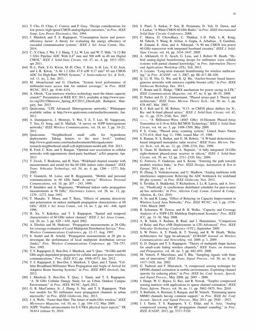
16
[61] T. Cho, D. Cline, C. Conroy, and P. Gray, “Design considerations forlow-power, high-speed CMOS analog/digital converters,” in Proc. IEEESymp. Low Power Electronics, Oct. 1994.
[62] J. Murdock and T. S. Rappaport, “Consumption factor and power-efficiency factor: A theory for evaluating the energy efficiency ofcascaded communication systems,” IEEE J. Sel. Areas Comm., Dec.2014.
[63] C.-Y. Chen, J. Wu, J.-J. Hung, T. Li, W. Liu, and W.-T. Shih, “A 12-Bit3 GS/s Pipeline ADC With 0.42 mm and 500 mW in 40 nm DigitalCMOS,” IEEE J. Solid-State Circuts, vol. 47, no. 4, pp. 1013–1021,apr 2011.
[64] H.-L. Park, Y.-G. Kwon, M.-H. Choi, Y. Kim, S.-H. Lee, Y.-D. Jeon,and J.-K. Kwon, “A 6b 1.2 GS/s 47.8 mW 0.17 mm2 65 nm CMOSADC for High-Rate WPAN Systems,” J. Semiconductor Sci. & Tech.,vol. 11, no. 2, Jun. 2011.
[65] M. Abouelseoud and G. Charlton, “System level performance ofmillimeter-wave access link for outdoor coverage,” in Proc. IEEEWCNC, 2013, pp. 4146–4151.
[66] A. Ghosh, “Can mmwave wireless technology meet the future capacitycrunch?” Presentation at IEEE ICC 2013, available at http://www.ieee-icc.org/2013/Mmwave Spring ICC2013 Ghosh.pdf, Budapest, Hun-gary, Jun. 2013.
[67] Qualcomm, “LTE Advanced: Heterogeneous networks,” Whitepaperavailable online at http://www.qualcomm.com/media/documents, Jan.2011.
[68] A. Damnjanovic, J. Montojo, Y. Wei, T. Ji, T. Luo, M. Vajapeyam,T. Yoo, O. Song, and D. Malladi, “A survey on 3GPP heterogeneousnetworks,” IEEE Wireless Communications, vol. 18, no. 3, pp. 10–21,2011.
[69] Qualcomm, “Neighborhood small cells for hyperdensedeployments: Taking hetnets to the next level,” [online]http://www.qualcomm.com/media/documents/files/qualcomm-research-neighborhood-small-cell-deployment-model.pdf, Feb. 2013.
[70] R. Ford, C. Kim, and S. Rangan, “Optimal user association in cellularnetworks with opportunistic third-party backhaul,” arXiv preprint, Apr.2013.
[71] T. Zwick, T. Beukema, and H. Nam, “Wideband channel sounder withmeasurements and model for the 60 GHz indoor radio channel,” IEEETrans. Vehicular Technology, vol. 54, no. 4, pp. 1266 – 1277, July2005.
[72] F. Giannetti, M. Luise, and R. Reggiannini, “Mobile and personalcommunications in 60 GHz band: A survey,” Wirelesss PersonalComunications, vol. 10, pp. 207 – 243, 1999.
[73] P. Smulders and A. Wagemans, “Wideband indoor radio propagationmeasurements at 58 GHz,” Electronics Letters, vol. 28, no. 13, pp.1270 –1272, June 1992.
[74] T. Manabe, Y. Miura, and T. Ihara, “Effects of antenna directivityand polarization on indoor multipath propagation characteristics at 60GHz,” IEEE J. Sel. Areas Comm., vol. 14, no. 3, pp. 441 –448, April1996.
[75] H. Xu, V. Kukshya, and T. S. Rappaport, “Spatial and temporalcharacteristics of 60 GHz indoor channel,” IEEE J. Sel. Areas Comm.,vol. 20, no. 3, pp. 620 – 630, April 2002.
[76] A. Elrefaie and M. Shakouri, “Propagation measurements at 28 GHzfor coverage evaluation of Local Multipoint Distribution Service,” Proc.Wireless Communications Conference, pp. 12–17, Aug. 1997.
[77] S. Seidel and H. Arnold, “Propagation measurements at 28 ghz toinvestigate the performance of local multipoint distribution service(lmds),” Proc. Wireless Communications Conference, pp. 754–757,Nov. 1995.
[78] T. S. Rappaport, E. Ben-Dor, J. Murdock, and Y. Qiao, “38 GHz and 60GHz angle-dependent propagation for cellular and peer-to-peer wirelesscommunications,” Proc. IEEE ICC, pp. 4568–4573, Jun. 2012.
[79] T. S. Rappaport, E. Ben-Dor, J. Murdock, Y. Qiao, and J. Tamir, “Cel-lular Broadband Millimeter Wave Propagation and Angle of Arrival forAdaptive Beam Steering Systems,” in Proc. IEEE RWS (Invited), Jan.2012.
[80] J. Murdock, E. Ben-Dor, Y. Qiao, J. Tamir, and T. S. Rappaport,“A 38 GHz Cellular Outage Study for an Urban Outdoor CampusEnvironment,” in Proc. IEEE WCNC, April 2012.
[81] G. R. MacCartney, Jr., J. Zhang, S. Nie, and T. S. Rappaport, “Pathloss models for 5G millimeter wave propagation channels in urbanmicrocells,” in Proc. IEEE Globecom, Dec. 2013.
[82] J. A. Wells, “Faster than fiber: The future of multi-Gb/s wireless,” IEEEMicrowave Magazine, vol. 10, no. 3, pp. 104–112, May 2009.
[83] 3GPP, “Further advancements for E-UTRA physical layer aspects,” TR36.814 (release 9), 2010.
[84] S. Pinel, S. Sarkar, P. Sen, B. Perumana, D. Yeh, D. Dawn, andJ. Laskar, “A 90nm CMOS 60 GHz Radio,” in Proc. IEEE InternationalSolid-State Circuits Conference, 2008.
[85] C. Marcu, D. Chowdhury, C. Thakkar, J.-D. Park, L.-K. Kong,M. Tabesh, Y. Wang, B. Afshar, A. Gupta, A. Arbabian, , S. Gambini,R. Zamani, E. Alon, and A. Niknejad, “A 90 nm CMOS low-power60 GHz transceiver with integrated baseband circuitry,” IEEE J. Solid-State Circuts, vol. 44, pp. 3434–3447, 2009.
[86] A. Alkhateeb, O. E. Ayach, G. Leus, and J. Robert W. Heath, “Hy-brid analog-digital beamforming design for millimeter wave cellularsystems with partial channel knowledge,” in Proc. Information Theoryand Applications Workshop (ITA), Feb. 2013.
[87] A. Lozano, “Long-term transmit beamforming for wireless multicast-ing,” in Proc. ICASSP, vol. 3, 2007, pp. III–417–III–420.
[88] Q. Li, H. Niu, G. Wu, and R. Q. Hu, “Anchor-booster based hetero-geneous networks with mmwave capable booster cells,” in Proc. IEEEGlobecom Workshop, Dec. 2013.
[89] C. Bontu and E. Illidge, “DRX mechanism for power saving in LTE,”IEEE Communications Magazine, vol. 47, no. 6, pp. 48–55, 2009.
[90] D. Parker and D. Z. Zimmermann, “Phased arrays-part I: Theory andarchitecture,” IEEE Trans. Microw. Theory Tech., vol. 50, no. 3, pp.678–687, Mar. 2002.
[91] K.-J. Koh and G. M. Rebeiz, “0.13- m CMOS phase shifters for X-,Ku- and K-band phased arrays,” IEEE J. Solid-State Circuts, vol. 42,no. 11, pp. 2535–2546, Nov. 2007.
[92] ——, “A Millimeter-Wave (4045 GHz) 16-Element Phased-ArrayTransmitter in 0.18-m SiGe BiCMOS Technology,” IEEE J. Solid-StateCircuts, vol. 44, no. 5, pp. 1498–1509, May 2009.
[93] P. E. Crane, “Phased array scanning system,” United States Patent4,731,614, filed Aug 11, 1986, issued Mar. 15, 1988.
[94] S. Raman, N. S. Barker, and G. M. Rebeiz, “A W-band dielectriclens-based integrated monopulse radar receive,” IEEE Trans. Microw. The-ory Tech., vol. 46, no. 12, pp. 2308–2316, Dec. 1998.
[95] X. Guan, H. Hashemi, and A. Hajimiri, “A fully integrated 24-GHzeight-element phased-array receiver in silicon,” IEEE J. Solid-StateCircuts, vol. 39, no. 12, pp. 2311–2320, Dec. 2004.
[96] G. Fettweis, F. Guderian, and S. Krone, “Entering the path towardsterabit/s wireless links,” in Proc. IEEE Design, Automation & Test inEurope, 2011, pp. 1–6.
[97] H. Zhang, S. Venkateswaran, and U. Madhow, “Analog multitone withinterference suppression: Relieving the ADC bottleneck for wideband60 ghz systems,” in Proc. IEEE Globecom, Nov. 2012.
[98] S. Tavildar, S. Shakkottai, T. Richardson, J. Li, R. Laroia, and A. Jovi-cic, “FlashLinQ: A synchronous distributed scheduler for peer-to-peerad hoc networks,” in Proc. Allerton Conf. Comm. Control & Comp.,Allerton, IL, Oct. 2010.
[99] A. So and B. Liang, “Effect of Relaying on Capacity Improvement inWireless Local Area Networks,” Proc. IEEE WCNC, vol. 3, pp. 1539–1544, March 2005.
[100] R. Schoenen, W. Zirwas, and B. H. Walke, “Capacity and CoverageAnalysis of a 3GPP-LTE Multihop Deployment Scenario,” Proc. IEEEICC, pp. 31–36, May 2008.
[101] A. B. Saleh, S. Redana, B. Raaf, and J. Hamalainen, “Comparisonof Relay and Pico eNB Deployments in LTE-Advanced,” Proc. IEEEVehicular Technology Conference (VTC), September 2009.
[102] S. W. Peters, A. Y. Panah, K. T. Truong, and R. W. Heath, “Relayarchitectures for 3gpp lte-advanced,” EURASIP Journal on WirelessCommunications and Networking, vol. 2009, p. 1, 2009.
[103] G. D. Durgin and T. S. Rappaport, “Theory of multipath shape factorsfor small-scale fading wireless channels,” IEEE Trans. on Antennasand Propagation, vol. 48, no. 5, pp. 682–693, 2000.
[104] M. Vetterli, P. Marziliano, and T. Blu, “Sampling signals with finiterate of innovation,” IEEE Trans. Signal Process., vol. 50, no. 6, pp.1417–1428, Jun. 2002.
[105] G. Taubock and F. Hlawatsch, “A compressed sensing technique forOFDM channel estimation in mobile environments: Exploiting channelsparsity for reducing pilots,” in Proc. IEEE Int. Conf. Acoust., Speech,and Signal Process., May 2008, pp. 2885 – 2888.
[106] J. Haupt, W. U. Bajwa, G. Raz, and R. Nowak, “Toeplitz compressedsensing matrices with applications to sparse channel estimation,” IEEETrans. Inform. Theory, vol. 56, no. 11, pp. 5862–5875, Nov. 2010.
[107] Y. Barbotin, A. Hormati, S. Rangan, and M. Vetterli, “Estimating sparseMIMO channels having common support,” in Proc. IEEE Int. Conf.Acoust., Speech, and Signal Process., May 2011, pp. 2920 – 2923.
[108] J. I. Tamir, T. S. Rappaport, Y. C. Eldar, and A. Aziz, “Analogcompressed sensing for RF propagation channel sounding,” in Proc.IEEE ICASSP, 2012, pp. 5317–5320.

17
[109] 3GPP, “Evolved Universal Terrestrial Radio Access (E-UTRA) andEvolved Universal Terrestrial Radio Access Network (E-UTRAN);Overall description; Stage 2,” TS 36.300 (release 10), 2010.
[110] G. Yuan, X. Zhang, W. Wang, and Y. Yang, “Carrier aggregation forLTE-Advanced mobile communication systems,” IEEE Comm. Mag.,vol. 48, no. 2, pp. 88–93, 2010.