military standard - mil-std-188everyspec.com/mil-std/mil-std-1100-1299/download.php?...-locked ln...
TRANSCRIPT

FIIL-STD-1295A(AV)
26 JUNE 1984
SUPERSEDINGPIIL-STD-1295(AV)
3 AUGUST 1981
It
MILITARY STANDARD
HIMAN FACTORS ENCINEERINC
DESIGN CRITERIA FOR IIELICOPTER
COCKPIT SLECTRO-OFTICAL OISPLAY SYUSOLON
XO OELIVEKABLE OATA REQUIRED BY THIS 00CUXENT
Downloaded from http://www.everyspec.com

HIL-STD-1295A(AV) I
DEPARTMENT OF OEFENSEWashington,DC 20301
Human Factors EngineeringCriteria for HeLicoptcc Cockpit Electr.o-DpticalSyu,bology
MIL-STD-1295A(AV)
1. ‘L%isMilitary Standard i~ approved for use hy the US Army Aviation SystemsCommand, Departmentof the Army, and is available for use by all DepartmentsandAgencies of the Department of Defense .
2. Beneficial comments (recommendations , additiom , deLetiom.) ard any Fr-tinent data which may be of use [n improving this document should be addressedto: US Army Aviation Systems Com.natK!, ATTN: DRSAV-ELS , 4300 CoodfellowBoulevard, St. Louis, MO 63120, by using the self-addressed StamiarrllzatlonDocument Improvement Proposal (DO Form 1426) appearing at Che end of this docu-ment or by letter.
I
Downloaded from http://www.everyspec.com

HIL-S?D-1295A(AV)
FORWARO
The intent of this document 1.sco scorrhrtitze the symbology used inrotary-vlng aircraft. In its present form, the etardard only applies covertical sit”atton displays IJtielectronic nttlcudc dlreccor Lmlicqcocs, thoughit is planned to expard the opplicnbilicy to Lncludc horizontal 81cuaciondisplays , bend-up displaye ard helmet mounted dtsplay.s. Also, che currentdocument 1s limited Ln the number of mlsn ion phases/segucnts for which symbologynre provided. Agntn, these phnscs/eegm@nta vll L be expanled as ndditiofmlinformacton is available.
One will notice that the 6ymbology provided herein is patterned after thntprovided for che AH-64. However, +ile the AH-66 symbology provided an Lnttlaldata base, it does not cenn the symbology, as preaenced Ln this document, 1s-locked Ln concrete.- ke neu symb.aLogy 1s developed or neu data becomesavailable to euggesc nlterncfom to current symbology, the appropriate changeswIL1 be ande co thts stnrdord, thereby always reflect ing the UIYSCup-to-date
symbol sets.
Lli
Downloaded from http://www.everyspec.com

MIL-sTD-1295A(AV)
Paragraph
1.1
1.2
1.3
2.
2.1
2.2
3.
3.1
3.1.1
3.1.2
3.1.3
3.1.4
3.1.5
3.1.6
3.2
3.2.1
3.2.2
3.2.3
..3.2.4
3.2.5
CONTENTS
SCOPE
purpose
Scope
ApplicatLon
REFERENCED DOCUMENTS
Issues of documents
Ocher publications ,
OEIJINITIONS
Display definitions
Helmet-aounteddisplay
Head-up display (HUD)
Electronic attitude diindicator (EADI)
(IWD)
ector
Vertical situation display (VSD)
Horizontal situation display
Multifunction display (MFD)
Information deftnitiorm
Coding characteristics
Command information
Mode
Predictive informar.ion
Oualitacive information
iv
(Hsu)
/
93s
1
1
1
1
2
2
2
2
2
2
2
3
3
3
3
3
3
3
3
Downloaded from http://www.everyspec.com

UIL-STIZ-1295A(AV)
CONTFATS-cent immd
Parugraph 3.2.6
3.2.7
3.2.8
h.
4.1
4. 1.1
6. 1.2
4.1.3
b.l.b
6. 1.5
4. 1.6
4. 1.7
4.1.8
4. 1.9
4.1.10
6.1.11
4.1.12
6.1.13
4.1.16
4.1.15
6.1.16
6.2
4.2.1
Qunnclc. cive Lnformatton
Status informntlon
Symbo1
CENESAL REQUIltstlENTS
Informncion presencotton elements
Limits tOX
Sensor line of si8ht reference
Helicopter reference symbol
Perforumnce management
Heading
Velocity veccor
Acceleration cursor
position reference
sate of climb
Ilorizon reference
Speed
41ticude
Side slip (trim indication)
Warning information
b ngc
Targeti~ information
Information displayed
Hode annunciation
v
Downloaded from http://www.everyspec.com

MIL-sTO-1295A(AV).“
Paragraph 4.2.2
4.3
6.3.1
4.3.2
4.3.3
4.4
5.
5.1
5.1.1
5.1.2
Table 1
Figures 1
2
3
4
5
6
ICONTENTS-continued
Mission segments
Informationpresentationcharacteristics
Informationform
Information location
Information control
Human engineering
DETAIL REQUIREMENTS ;
Head-up/helmet-mountedldisplays
Information
HUD/HMD mission mode-informationmati-ix
TABLES
ttUD/tUDmisslo” segment-tnfomation wtrix
FIGURES
Sensor gimbal Limits box
Sensor Line of sight reference
Helicopter centerline rdference
Performance management
Heading
Velocicy vector
7
9
9
10
10
10
10
10
10
10
13
14
15
16
17
Ig
vi
Downloaded from http://www.everyspec.com

NII.-STCI-1295A(AV)
CONTSNTS-cent inued
Figures 7
8
9
10
11
12A
120
I2C
12D
12E
“13
14
15
16
17
18
19
20
21
22
23
26
PnlJ_e
Acceleration curtmr 19
Ymsltion rafecencc 20
Race of climb 21
Horizon reference 22
Speed 21
Single digital altitude display 26
OUal ,iigitalaltitude dispiay 26
Single nnolog nlticude display 25
Dual analog nlcitude dlspiay 25
SiIUU1tOIWOUS digital/analog dispIay 26
Side slip 27
Uarntng syabol (.Jor Vnrn) ?s
Snngr? 29
Target boring .30
Aiming reticle 31
Target ttcsignacion 32
Ueapons/ordance SC8CUS 33
General nrrarrgement; hovor sndc example 34
General arrangement; Posit Ion made exaraplc 3s
Ceneral orrangtiaenc: cramition mde example 36
Ccnerai arrungcuent ; cruise code example 37
Generai arranga:nenr;wapan deiivcry 38
mode example
vii
Downloaded from http://www.everyspec.com

f41L-sTD-1295A(AV)
1. smec
1.1 Purpose. The purpose of this stnndnrd 1s to establish human factors design
crlcerln for IJymbolicand olphummeric infonnacton used on electronically awloptically gerteratedairborne displays. Electronically ad optically generateddisplays are chose in which an image is presented to the observer directly on .the image-generati~ surface or indirectly chrwgh an optical projection system.The symbolic presentation provides flight, combat, ard tnrgo-haraffirtginfor-❑at ion with or without video imagery for rotary-wing aircraft. Wenpon status
and fault decectionilocotion scacua meeengcs may also be presented. This lrtan-dard 1s restricted to those disploy devices used in aircraft for the purpoee offlight or miesion control. Separate radar or electronic warfare displays arenot included.
1.2 =. This standard establishes general information, .symbology,amfdisplay format requirements for hover, position, tramition, cruise nmJ weapondelive~ modes of rotnry+ing alrcroft missions.
1.3 Application. This stnniard shnli be npplied co vertical eituacion displays
amd electronic attitude director imficntors that present flight and cOmbatinformation.
2. REFERENCED DIXUHSNTS
2.1 Issues of docume.nre. The foliowing documents of the issue in effect on
date of invitation for bids or requests for proposal form a part of thisstatdard co the extent specified herein:
)lilitoryStandards
HI L-STP-d iI Aircrew Station Signals
NIL-STD-783 bqfends for Use in Aircrew StotiotHONI on Airborne Equipment
)IIL-STD-1472 !lucnn Knginecrims Design Criceri O for:iilitarySystems, Equipc@nc am!Facllittes
Downloaded from http://www.everyspec.com

IMIL-STD-1295A(AV)
/(Copies of specifications , standards, drawings, and publications required bycontractors in connection with specific procurement functions should be obtainedfrom the procuring activity or as directed by the contractingofficer.)
2.2 Other publications. None.
3. DEFINITIONS
3.1 Display Definitions
3.1.1 Helmetmounted display (HMD). The HMD is a display uitichprojects videoimagery, symbolic and/or alphanumeric information on a display medium (e.g.,combinimg glass or visor) into one or both eyes of the airccewmember. In Llk3st
aPPlicatiO~ the display medium is attached co a flight helmet which is part ofa head tracking system. The line of sight of the helrnec is determined by thehead tracking system and a de.sigmted sensor is slewed in a one-to-one angularcorrespondence with this line of sight. The display medium then displays theimage from the designated sensor: television (TV), forward looking infrared(FLIR), or scan coverted radar. Specific symbo~ and formats can be selectablefor a given uncleof operacio”.
3.1.2 Head-up display (HUD). The HUO is a display which projects collimatedsymbolic information into the aircrewmember’s forward field-of-view. The tech-nique results in the combination of flight control and weapon delivery infor-❑ation with external visual cues from the scene’normally viewed through thewindscreen. Specific symbols and formats c.a”M selectble for a give” mode ofoperation. Take-off, landing, mivigaclon, hover, bob-up, terrain-following/avoidance, sling load transportation, air-co-air, and weapon delivery modes maybe provided. Video formats may also he displayed, such as TV, FLIR, or sca”-coverted radar, along with symbology.
3.1.3 Electronic attitude director indicator (EADI). The EAD1 is a replacementfor the standard ADI, but with no moving parts other than controls ad switches.The EAD1 presents che symbols on a display usi~ either a CRT or direct viewflat plate technology. gasic syrnbologycow ists of an aircraft symbol; verticaland horizontal director indices (when applicable); heading information; andline, sky-ground color or shading separation for hor~zon reference. If desired,other symbols ca” be generated a“d displayed by node selecrio”, such as inscru-ncnt landing system (ILS) window, collective, cyclic a“d yaw command, airspeeddeviation, altitude, flight path, predicted flight path, range, et cetera.Specific symbols and formats ca” be selectable for a given mode of operation.Modes may consist of take-off, landing, hover, cruise, weapon delivery, and off.
3.1.4 Vertical situation display (vSO). The VS’Jhas all of the features of anEADI, vith the increased capability of displayirug sensor data. Additional nmdesmay consist of TV, infrared (lR), attack radar, weapon 3%!,or tecrain-fo llot..lngradar. Specific symbols and formats ca” be selectable for a gLve” mode ofoperation. When any mode ocher than one of che primary EADI modes is selected ,the VSO may present basic symbolic information ,for flight control superimposedon the sensor data.
2’
Downloaded from http://www.everyspec.com

WL-STD-1295A(AV)
3.1. S Horizontalsituation display (HSD). An HSD is n display *ich aids the
crew members in navigation. Basically, it corsiste of heading, distance-to-go,bearing-to+ lstlmtion or no= ocher mvigation facility or reference, track,map, ccurse, oircrafc position,and steering error. nodes my Comist ofmamxil, north-up, track-p, data, test, and off. Selectlon of map scale factommay also be provided. Navigation update con be accomplished vith the propercomputer techniques. The HSD also has the capability of combinirqteymboln withthe map information. Syubo2s may be used for nnnotatlon of the projected map,
such as check points, various legs of the mia.sion,high-rtek areas, crac”kdeviation, nmi radar homing ami warning. Specific frodcsamf fomcs can t-e
selectable for a given =de of operation.
3.1.6 l!ultifunctiondisplay (KPD). The HFD la n general-purpose display which
UL8Ybe ueed in m.ny places in che cockpit. In addition to the audee listed for
the VSD nnd HSO, ocher possible uodes ore enorsy management, e%ine ~nage.zent,aircraft subsystem information, atwi integrated test and maintenance. Spetificmodes atulformats can be selectable for n given nude of operation.
3.2 Information definitions
3.2.1 CodiM characteristics. Coding chorncteristics are readily identifiable
attributes couuonly associated with o eymbol by meorm of which .wch symbols aredifferentiated; e.g. , size, shape, color.
3.2.2 Commrtd information. timmti information is displayed qunlitncive infor-
mation directirg o control oction.
3.2.3 !iode. A mde is the functional state of the display arxflorcontrol
system(~ A mode can be curamlly or nucomaticnlly selected.
3.2.4 Predictive information. Predictive information 1s information prediccirgfuture status, condition, or poaiclon of the nircrnft, a system, or a subsystem.
3.2.5 QualicticIve information. Qunlicntive information is information pre-
sented by a disploy in a =nncr which permits the display user to assess theinformation without requiring attention to an exact mcterical qunntity.
3.2.6 Quantitative information. quantitative information IS information pre-sented by n dispiay in n msnner which permits the display user co otserveor extract a mmericnl value onsocir.ted with the information. Quanticnciveinformation may be displayed in either disical or UW1OR nlphnruuerics .
3.2.7 Status inforantion. Stucus information (qunntitntive oc qualicstive
tYpe) is Current ComiLtion information about the nlrcraft and its surrc.umilngs.
3.2.B =. A symbol is n gcc.metric form or olphamn?ric information used torepresent the scocc of a pnrnmecer on o display.
3
Downloaded from http://www.everyspec.com
MIL-STD-1295A(AV)
/4. CSNESAL SEQUII(SMENTS
4.1 Informationpresentationelements. The symbols, as portrayed in thefigures, are not intended to itiicate relative size. The intent is to p.3rtrayonly the shape of the symbol and the relative limation of the symbol within thedisplay area.
4.1.1 Limits box. The limits box represents the angular elevation and azfmuth-traveraimg limits of a weapon or semor (see Fig. 1).
4 .1.2 Sensor line of sight reference. The seffiorline of sight referencesymbol is fixed at the center of the display providing a reference for aircraftposition symbols , weapons steering, hover symbols , awl attitude information (seeFig. 2).
4.1.3 Helicopter reference symbol. The helicopter referemce symbol representsan extension of the aircraft center line (see .Fig. 3).
4.1.4 Performance management. Performance management information may be pre-
sented in either a digital or analog format. IiIan analog presentation, thedisplay shall be a @mvlng index against a fixed scale (see Fig. 4).
4.1.4.1 Lift margin. ‘i%elift margin symbol shall concirmouslyindicate theamount of lift capacity remaining.
4.1.4.2 Power margin. Power margin shall continuously indicate the difference
between power being demanded and power available.
4 .1.4.3 Torque. The torque symbol shall provide the necessary it?dicationof
approach to and passage through red line torque values.
4. 1.5 Heading. Heading (degrees) information should be displayed as analoginformation ad shall be located on the display’as shown in Fig. 5. The display
shall have a moving tape compass reference scale with a fixed aircraft headirgindex mark. ‘rhedisplay should have 10” increments with alphammerics presented
every 30”. The heading scale shall have a minimum of 90”. Cardiml heading
shall be letters. The heading index shall be a verttcal line.
4.1.6 Velocity vector. The velocity vector is a solid line symbol which repre-
sents the speed and direction of helicopter movement in a hortzoncal plane. Thepoint of origin for the velocity .veccor.LS the ‘centerOf the applicable d!splay.The length of the vector as measured from its point of origin represents speedof ❑ovement, and the angular deflection Of the ‘vectOr as measured frOm the X adY axes represents direction of movement (see Pig. 6).
I!
I
I
Downloaded from http://www.everyspec.com
PIIL-STO-1295A(AV)
4. 1.7 Acceleration cursor. The nccelerecion cursor 1s aaencs helicopter acceleration in a horizontal plane. The
symbol which repre-point of origin for
the accelerationcureor is the extemjed tip of velocity vector. The s~cingbetween this tip and the acceleration curoor cepreeencs the magnlcude of acce-leration oml the direction of displacement from thin tip representsthe direc-tion of acceleration(see Fig. 7).
b.1.8 Fosicion reference. The position reference symbol in o dynamic symbolused as o precise ground reference point. The potnt of origin for the positionreference symbol is the cemer of the applicable display. ~is symbol uovesfcon its point of origin at a rate equivalent, and in a direction opposite, tothe velocity of the helicopter (see Fig. 8).
4.1.9 Rate of climb. The rote of climb symbol imlicaces the rate of ascent ordecant of the helicopter with the ID.Jllpoint centered at the vertical center ofthe display. This symbol shall & o roving index against a fixed scale (seeFig. 9).
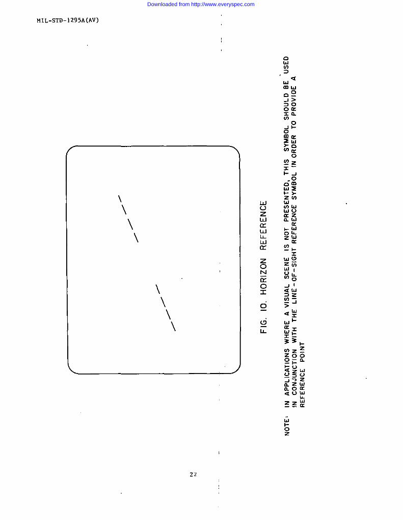
6.1.10 Horizon reference. This symbol indicates the pitch and roll accitude “ofthe helicopter relative to the horizon. This symbol shall be trimmable in bothpitch and roll (see Fig. 10).
4.1.11 e. Speed information may be displayed as onnlog or digital infor-mation ad may be displayed as indicated airspeed, true airspeed or ground speed
os required. The predomimnc ly displayed epeed should noc require iden-tification. Speeds that appear infrequently should be encoded using thefollowi~ codes:
a. LAS - Indicated Airspeed
b. TAS - True Airspeed
c. CS - Cround speed
If ground speed is displnyed,(see Fig. 11).
the unit of meno”remenc shall also b displayed
4.1.12 Altitude. Altitude information may be presented M nbsolute atifor
barometric altitude, atxfmay & displayed in digital andlor analog format.
4.1.12.1 Digital altitude. A“digitnl aLtIcudc prese”tatlon shall consist of
the number of digits required co precisely di6plny the desired rdtttude infor-mation. A single“digitalpresentationshall be located on the vertical centerline of the display (see Fig. 12A); n dual digital presentation shrillbe sym-metrically located above and below the vertical centerline of the dteplay (seeFig. i2B).
5
Downloaded from http://www.everyspec.com

MIL-STD- 1295A(AV)
4.1. 12.2 Analog altitude. An analog altitude presentationshall comsiat ofnine 8tationaryhorizontal scaling lines arranged vertically above one anotherwithout lateral boundary lines , ariia moving thermometer-type indicator. Thehorizontal scaling lines, shall be grouped as depicted in Figure 12C with ihethird Une from the top located on the vertical Center Une of the display. Thethermometer-type indicacor shall be leas tide than the scaling lines so that thelines shall be visible to the side(s) of the Lndlcator.
4. 1.12.3 Absolute/barometric altitude. If both absolute ad barometric a2ti-tude information are to he displayed simultaneously, barometric altitude shallbe positioned above absolute altitude In a dual digital format, farther from thecenter of the display in a dual analog format, ard as an analog scale , fartherfrom the center of the display in a dtgitallanalog format (see Fig. 12E). Ifboth absolute and barometric altitude information are to be displayed non-simultaneously, the less commonly displayed altitude shall be encoded with thef01lowing code.
Altitude TypeTo Be Encoded Digital Analog
Absolute Boxed “A‘“
Barometric Boxed “’B”
4.1.13 Side slip (trim indication). This display is a symbolic representationof a standard side slip indicator and should duplicate its function (seeFig. 13).
4.1.14 Warning information. Uar”ing information such as the type established
in MIL-STD-LI 1, or threat warning, may be displayed either symbolically or bylegend (see Fig. IL).
Range is the distance (either siant or hocizoncal , as
~~~il~ab=~om cl,=aircraft co a predetermined point (see Fig. *5).
4.1.16 Targeting information.
4. 1.16.1 Target bearing. This information should indicate the relaclve bearingof the target from the helicopter (see Fig. 16).
4 .1.16.2 Aiu,i”greticle. The aiming rec.tcleshall designate the predicatedimpact point of projectiles and shall operate in a dynamic or fixed imde as
appropriate (see Fig. 17).
6
Downloaded from http://www.everyspec.com

141L-sTo-1295A(AV)
l%e carnec deeiunatlon BYmbol shill overlay the4.1.16.3 Target designation.tar!zeton the video image when the Cnrget data-is stored in the aircrof c com-put~r. This vill provi~e n cue for the aircrew in target acquisitionwhen thetarget ia noc clearly visible on the display. The symbol should blink or pro-vide other feedback cuee to icdicate designation (see Fig 18).
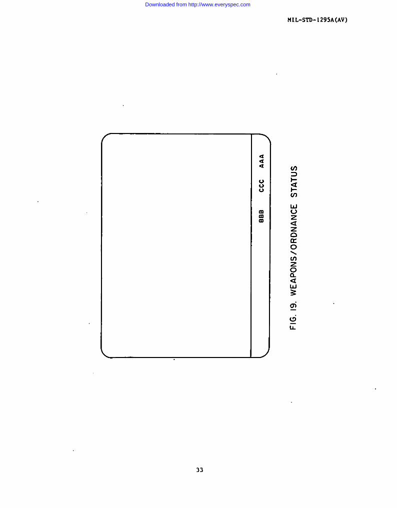
4.1.16.4 Weaporw/ordance status. Thie informe.cban ehould indicate the acacus
of the weapons and on-board ordnance (see Fig. 19).
4.2 Informationdieplayed. The displays shrillprovide informationcoveringprlmarj mission seguantm ad the information which requires visuol assessmentdurimg that mission seguenc. The mission segments covered by thin standard orehover, position, tra=ition, cruise and weapon delivery. Commaml, status, adweapon &livery information ore appropriate for all tmdee of flight selected.They shall appear aa required by the mission segment of concern.
6.2.1 tiodeannunicacion. If more than one ande other than Off or StamJby is
selectable, each umde selected ehall be indicated on the display or on on adja-cent control panel.
6.2.2 Kission segments. Symbology modes are intemied co enhance the data pro-vided by sermor eleccro-pticnl imagery while minimizing disploy clutter.Symbology modes are parciculary applicable to night ntxi/or limited visibilityoperations.
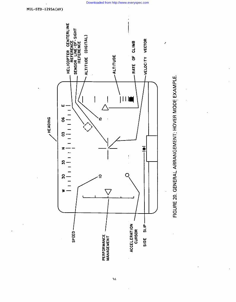
4.2.2.1 Hover mode. The hover wde is intem+ed for o fllght environmentinvolvinghover operociornchnroccerlzedby no, or very low, speed. As a cdni-mum, the hover mode shall incorporate:
a. Helicopter line of eight reference.b. Se-or iine of eight reference.c. Heading information.d. Speed information.e. Altitude information.f. Vertical velocity information.
8. Side slip informocion.h. Performance uu3nngement information.
Velocity veccor.
;: Acceleration cursor.See Fig. 20 for an example of hover mode symbology.
1
Downloaded from http://www.everyspec.com
HIL-STD- 1295A(AV ) I
4.2.2.2 Position mode. The position uude is iritet-dedfor a flight environmentrequiring a precision hover capability. The position mode provides referencesymbology for hovering operations in relation to a selected point on the ground.As a minimum, the position code shall incorporate:
a. Helicopter line of sight reference.b. Sensor line of eight reference.c. Heading information.d. Speed information.e. Altitude information.f. Vertical velocity information.
g. Side slip infornmtion.h. Performance management information.
Velocity vector.
:: Acceleration cursor.k. Position reference.
See Fig. 21 for an example of position mode symbology.
4.2.2.3 Transition mode. The crarsftion mode is interded for a flight environ-
ment involving takeoffs, landings and ocher operations characterized byvariable low speeds and altitudes. AS a m.initnuti,the Crarsiclon mode shall
Helicopter line of sight reference.Sensor line of sight reference.Heading information.Speed information.Altitude information. ,
vertical velocity information.I
Side slip information. I
Performance management information. IVelOcity vector.Acceleration cursor.Horizon reference. ~
incorporate:a.b.c.d.e.f.
l?.h.i.
j.k.
See Fig. 22 for an example of transition mode s$mblogy.
I
8
I
Downloaded from http://www.everyspec.com

HIL-STD-1295A(AV)
6.2.2.4 Cruise mode. The cruise umde is intemied for n flight environmentchnracterlzed by relatively cortscancalrspeede, altitudes, at-dcoureea.Generally, airspeeds will be fneter,.altitudes will be higher, and course Sineswill b core definite than in other -dee of flight. b o mtmzum, the cruisemode shrillincorporate:
a.b.c.d.e.f.
a.h.1.
Iklicopter line of sight reference.Semor Line of eight reference.Heeding lnformntlon.Speed information.Altitude information.Vertical velocity information.Side slip information.Performancemanagement Information.Horizon refecence.
See Fig. 23 for an example of cruise aede symbology.
4.2.2.5 Weapon delivery rode. The weapon delivery -de supplies symbolic
Lnformatton for surveillance, designnclon, or ordnnnce delivery. l%is nude may
be used in conjunctionwith any of the flight modes. See Fig. 24 for an exampleof t,eapondollvery mode symbology.
6.3 Information presentation character iscice.
4.3. I Information form.
4 .3.1.1 Information. Information presented by the displays shall be in sym-
bolic, pictorial, or alpharnmsric forms as specified by the procuringactivity.
4.3.1.2 =. The m?oning and motion of symbols shall be co-istent
throughout al1 modes of the display. Scollng nnd gain chnoges are permttted
between males.
6.3.1.3 -. hch symbol ehalL be unique by virtue of at least two codingcharacceriecics. The use of either a raster, caligrophicor x-y matrix displayshall not adversely affect these codimg characteristics.
6.3.1.6
pacible
4.3. 1.5
be used
Notion. TIIese-e of oircroft control symbol motion should be com-
wlth the IIOC1OW of the corresponding controller.
Color-codin@ Calor-codlng my be used, oml flashing of symbols shalt
sparingly.
Downloaded from http://www.everyspec.com

MIL-STD-1295A(AV)
4.3.1.6 Numbers. At least three distinct sets of rmmbers shall ‘appear
times on analog displays using moving scales such as heading, speed andaLtitude.
at all
4.3.1.7 Legends. All legends shall be in accordance with MIL-STO-783 or be
approved for use by the procuring activity.
4.3.2 Information location. Location of the symbols on displays shall be in
accordance vith Figures 20-24, as applicable.
4.3.3 Information control.
4.3.3.1 Symbol brightness shal1 be concinouRly adjustable to provide 8ymbol
Legibility under all ambient light conditions. Contrast ratio my be aucomaLi-cally maintained at the selected level. During all modes of flight, all alpha-numeric information may be eliminated by adjustment of the luminance level.
4.3.3.2 A declutter control shalL be provided which eliminates certain prese-
lected symbolic information.
4.4 Human engineertn~. Human engineering shall conform to MIL-STD-1472. The
scalinglsizing of symbols shall be such that the symbol @hall subtend not lessthan twenty minutes of visual angle . Image qtiality shall be consistent with the
operator’s needs.
5. DETAIL
5.1 Head-uplhelmec-mou nted displays.
REQUIREMENTS
5.1.1 Information. The HUD/H??Dshall present all essential flight and mission
information. All information reflected from the dLsplay shall be collimated amfof sufficient brightness to be seen in a real-world background of 10,000 foot-candles illumination. The information displayed is determined by the require-ments of the modes of operation.
5.1.2 HUD/HMD mission mode information matrix. Information related to variousmisston modes 18 shown on Table 1.
10
Downloaded from http://www.everyspec.com

Custodian:
Amy - Av
Review accivitiea:
tiIL-sTD-1295A(AV)
Preparingactivity:
Army - AV
Project UF’AC-AO12
Downloaded from http://www.everyspec.com

MIL-STO-1295A(AV)
Table I. HUD/HMD/VSD MISSION llOD~-INFOFWATION MATRIXI
IMODE
NFORMATION HOVER POSITION TRANSITION CRUISE WSAPON
Helicopter LOSSemor LOSHeadlrugSpeedAltitudeVertical VelocitySide SlipHorizon ReferenceAn Acceleration CursorA Velocity VectorPosirion ReferencePerformance ManagementSensor Gimbal LimitsSensor FOV LimitsRange to TargetSolved ReticleUnsolved ReticlePre-firing Maneuver
ConstraintsPOSt-Firing Maneuver
ConstraintsWeapons/Ordnance StatusWarning
x xx xx xx xx xx xx x
x xx x
xx x* ** **II *//●# ●o*IJ *//
*# */)
*# *#*5 *#* *
X = Required* = Optionalt. Selectable to minize display clutter
xxxxxxxxxx
~. xI*
●
●!II *R
●#
*#
*/)*5
,*
xxxxxxxx
x●
*●O x*R x*# x
●O x
●R x●/) x● x
NOTE: Weapon delivery mode may be used in conjunction with other modes.
121
Downloaded from http://www.everyspec.com

FIIL-STD-1295A(AV)
13
Downloaded from http://www.everyspec.com

MIL-sTD-1295A(AV)
I
I—. I
In-1-
Downloaded from http://www.everyspec.com

HIL.?,TD- 1295A(Av)
,.,
.
Is
Downloaded from http://www.everyspec.com

MIL-STD-1295A(A
y
II
I
!1
I
I
(
g
lb
Downloaded from http://www.everyspec.com

1’
!IIL-STD-1295A(AV)
g
Eaw1u)
17
Downloaded from http://www.everyspec.com

MIL-sTD-1295A(AV)
\l/i‘1–
u-
18
Downloaded from http://www.everyspec.com

/
HIL.sTD-1295A(AV)
19
Downloaded from http://www.everyspec.com

MIL-STD-1295A(AV)
I
oI
I
--— I
Downloaded from http://www.everyspec.com

PIIL-sTD-129SA(AV)
--J--
u.0
05
21
Downloaded from http://www.everyspec.com
MIL-sTD-1295A(AV)
\
\
\
\
\“\\\
22
—
Downloaded from http://www.everyspec.com

MIL-sTD-1295A(AV)
I I 1-
(
Idm
0wwa(/Y
_
Downloaded from http://www.everyspec.com

MIL-sTD-1295A(AV)
I0 0go
IL
Downloaded from http://www.everyspec.com

I
TI I I 1-/
tiIL-STD-1295A(AV)
%
2mz
25
Downloaded from http://www.everyspec.com

MIL.sTD-1295A(AV)
oIn
26
Downloaded from http://www.everyspec.com

MIL-STD-1295A(AV)
m-i
27
Downloaded from http://www.everyspec.com

MIL-STD- 1295A (AV)
I
.
I
28
in
Downloaded from http://www.everyspec.com

MIL-STD-1295A(AV)
29
Downloaded from http://www.everyspec.com

MIL-sTO-1295A(AV)
c1zEawm
EwwCKa1-
W—
b—IL
30
Downloaded from http://www.everyspec.com

MIL.sTD-1295A(AV)
I
——. —
I
31
nu1-g0I&l
n
Downloaded from http://www.everyspec.com

MIL-sTD-1295A(AV)
1-a
5?5wn
t-W0lxa1-
ai6r
Downloaded from http://www.everyspec.com
!IIL-STD-1295A(AV)
6—
w—LL
33
Downloaded from http://www.everyspec.com
MIL-STD-1295A(AV)
I
L-
?/,
Downloaded from http://www.everyspec.com

FIIL-STD-1295A(AV)
L
I II
35
Downloaded from http://www.everyspec.com

MIL-STD-1295A(AV)
z—— —
/
36
I
Downloaded from http://www.everyspec.com

IIIL-STD- 1295A(AV)
I-
z —— .—. —
37
Downloaded from http://www.everyspec.com

I
MIL-STD- 1295A(AV)
z —— —.—
IP-l~—
o_ml
3—
-
1rLd
1
38
Downloaded from http://www.everyspec.com

STANDARDIZATIONDOCUMENTIMPROVEMENTPROPOSAL(Seelmtructimu- R
DOCUMENTNUMBER Z 00cuuENT TITLEIL-STD-1295A(A) HELICOPTER COCKPIT ELECTRO+PTICAL DISPLAY $YMSQIJXYNAMEOFSUBM1~lNOOROAN,ZATION 4. 17P!! OP0noAN12aT10N (Mu4W)
❑ “ENDOB
❑ La,[email protected]:ty.81U8,ZIPCnda)
.: ❑ MAN”PACT”RSR
❑ 0?!’=. ,S#Ocw,:
PROOLEMAREASa Pw~@ N“,nb ~ WOtilW!
,.
h mwmnnnam WOrdlnw
. . i3-”/R.tlo”.,. f., Ranmm.d#ll.,w
REMARKS
..=
. NAMEOFSUBMITTERh..nt. Fht. Ml) - ClO,lula ~ b. WORKTELEPMONSNUMOER(lncti A-cdl ) -0.,10”.1
MAIL,“0 AOORES9(sm.,. CI*, .9ti10.ZIPcd) - O*,lnn* B, DATEOFSUBMISSION(YVMMDDJ
mm ----- -----Uu ;“;:. 1Wi PREVIOUSEDITION ,s o@so LETE,
I
Downloaded from http://www.everyspec.com