military munitions response actions - interstate …€¦ · · 2013-11-08military munitions...
TRANSCRIPT

EM 1110-1-4009 15 June 2007
“Approved for public release; distribution is unlimited.”
ENGINEERING AND DESIGN
MILITARY MUNITIONS RESPONSE ACTIONS ENGINEERING MANUAL


EM 1110-1-4009 15 Jun 07
AVAILABILITY
Electronic copies of this and other U.S. Army Corps of Engineers publications are available on the Internet at http://www.usace.army.mil/inet/usace-docs/. This site is the only repository for all official USACE engineer regulations, circulars, manuals, and other documents originating from HQUSACE. Publications are provided in portable document format (PDF).

This page intentionally left blank


i
DEPARTMENT OF THE ARMY EM 1110-1-4009 U.S. Army Corps of Engineers CEMP-CE Washington, DC 20314-1000
Manual No. 1110-1-4009 15 June 2007
Engineering and Design MILITARY MUNITIONS RESPONSE ACTIONS
TABLE OF CONTENTS
Paragraph Page
Chapter 1. Project Planning and Execution
Introduction.............................................................1-1 1-1 Project Delivery Team (PDT).................................1-2 1-1 Technical Project Planning (TPP)...........................1-3 1-2 Safety ......................................................................1-4 1-6
Chapter 2. Project Contracting Requirements
Introduction.............................................................2-1 2-1 Developing the SOW ..............................................2-2 2-1 Cost Estimating Process..........................................2-3 2-5 Project Schedule......................................................2-4 2-7
Chapter 3. Site Visit
Introduction.............................................................3-1 3-1 Site Visit Objectives and Planning .........................3-2 3-1 Site Visit Attendees.................................................3-3 3-2 Site Visit Requirements ..........................................3-4 3-2
Site Visit Information Collection............................3-5 3-3
Chapter 4. Work Plans
Introduction.............................................................4-1 4-1 Performance Objectives ..........................................4-2 4-1 Work Plan Review ..................................................4-3 4-1 Work Plan Contents ................................................4-4 4-1 Work Plan Acceptance............................................4-5 4-4

EM 1110-1-4009 15 Jun 07
ii
Paragraph Page
Chapter 5. Geospatial Data Systems (GDS)
Introduction.............................................................5-1 5-1 Requirements for the Acquisition and Access of Geospatial Data.......................................................5-2 5-1 Data Quality Objectives..........................................5-3 5-1 QC...........................................................................5-4 5-4 SOW........................................................................5-5 5-4 GDS Plan ................................................................5-6 5-6 Planning Considerations .........................................5-7 5-7 Mapping ..................................................................5-8 5-9 Deliverables ............................................................5-9 5-10
Chapter 6. Geophysical Planning Strategies for Response Actions
Introduction.............................................................6-1 6-1 Specific Response Goals and Needs to be Addressed by Geophysical Investigation................6-2 6-1 Specify the Removal Decision Strategy .................6-3 6-3
Chapter 7. Site Characterization
Introduction.............................................................7-1 7-1 MRS Footprint Identification..................................7-2 7-1 Sectorization ...........................................................7-3 7-8 Geophysical Site Characterization Strategies .........7-4 7-9 Sampling Methods ..................................................7-5 7-11 Excavation ……………………………………......7-6 7-13 Data Interpretation, Resectorization, and Decision Making.....................................................7-7 7-14 Geophysical Investigation Planning Tools .............7-8 7-14
Chapter 8. Geophysical Investigation
Introduction.............................................................8-1 8-1 Geophysical Systems ..............................................8-2 8-1 Geophysical Tools ..................................................8-3 8-2 Positioning and Navigation Techniques .................8-4 8-13 Geophysical Systems Deployment Platforms.........8-5 8-24

EM 1110-1-4009 15 Jun 07
iii
Paragraph Page
Anomaly Selection Criteria and Anomaly Prioritization…………………………………… ...8-6 8-27 Anomaly Resolution ...............................................8-7 8-34 Special Considerations for Planning Geophysical Investigations ..........................................................8-8 8-36 Geophysical System Capabilities and MEC Detection Capabilities…………………………….8-9 8-37 Digital Data Format and Storage and Coordinate Reporting.................................................................8-10 8-39 Geophysical Prove-Out Planning............................8-11 8-40 Data Analysis and Interpretation ............................8-12 8-44
Geophysical Work Plans.........................................8-13 8-46
Chapter 9. Quality Control of Geophysical Systems and Related Operations
Introduction.............................................................9-1 9-1 Process Quality Management .................................9-2 9-2 Product Quality Management .................................9-3 9-16 Managing Quality Control Failures ........................9-4 9-18 Special Considerations for Quality Control Programs .................................................................9-5 9-20
Chapter 10. MC Sampling
Introduction.............................................................10-1 10-1 Objective .................................................................10-2 10-1 Initial MC Investigation Planning...........................10-3 10-2 Sampling and Analysis Considerations ..................10-4 10-3 Types of MC Analyses............................................10-5 10-8 Sampling and Analysis Plan ...................................10-6 10-18 Data Interpretation, Validation, Reporting, and Decision Making.....................................................10-7 10-19 Quality Management...............................................10-8 10-21
Chapter 11. Blast and Fragment Protection................................
Introduction.............................................................11-1 11-1 DQOs ......................................................................11-2 11-1 Explosives Safety Considerations...........................11-3 11-1 Explosive Effects ....................................................11-4 11-3

EM 1110-1-4009 15 Jun 07
iv
Paragraph Page
MSDs ......................................................................11-5 11-5 Unintentional Versus Intentional Detonation Minimum Separation Criteria .................................11-6 11-6 Unintentional Detonations ......................................11-7 11-6 Intentional Detonations...........................................11-8 11-6 Explosives Siting Plan ............................................11-9 11-7 Engineering Controls ..............................................11-10 11-10
Chapter 12. Risk Characterization
Introduction.............................................................12-1 12-1 CSM ........................................................................12-2 12-1 MEC Risk Pathway.................................................12-3 12-1 Risk Management Principles ..................................12-4 12-4 Risk Characterization Methods...............................12-5 12-5 Risk Communication ..............................................12-6 12-6
Chapter 13. Quality Assurance Surveillance Plan (QASP)
Purpose and Overview ............................................13-1 13-1 Responsibilities .......................................................13-2 13-1 QASP Overview......................................................13-3 13-2 QASP Metrics .........................................................13-4 13-3 QASP Surveillance .................................................13-5 13-3 QASP Non-Conformances......................................13-6 13-4 QASP Review Documentation ...............................13-7 13-5
Chapter 14. Corps of Engineers Contractors MPPEH Inspection, Certification, and Final Disposition Procedures
MPPEH – Contractor Responsibilities and Procedures...............................................................14-1 14-1 MPPEH – Certification and Verification................14-2 14-3 Maintaining the Chain of Custody and Final Disposition ..............................................................14-3 14-4 Material that is still MPPEH after inspection may be released only to a qualified receiver...................14-4 14-5

EM 1110-1-4009 15 Jun 07
v
APPENDICES
Appendix A – References .................................................................................................. A-1
Appendix B – Checklist Tables ..........................................................................................B-1
Appendix C – QASP Template ..........................................................................................C-1
Appendix D – QASP Metrics ............................................................................................ D-1
Appendix E – Surveillance Activities Table......................................................................E-1
Appendix F – Corrective Action Request (CAR) ...............................................................F-1
Appendix G – Generic On-Site QA Checklist ................................................................... G-1
Appendix H – EE/CA Work Plan Review Matrix ............................................................. H-1
Appendix I – EE/CA Report Review Matrix.......................................................................I-1
Appendix J – Removal Action Work Plan Review Matrix..................................................J-1
Appendix K – Sample Quality Assurance Report (QAR) ................................................. K-1
Appendix L – After Action or Final Quality Assurance Report Content ...........................L-1
Glossary .........................................................................................................Glossary-1

EM 1110-1-4009 15 Jun 07
vi
This page intentionally left blank

EM 1110-1-4009 15 Jun 07
1-1
CHAPTER 1 PROJECT PLANNING AND EXECUTION
1-1. Introduction.
a. General.
(1) The U.S. Army Corps of Engineers (USACE) conducts munitions responses under the Military Munitions Response Program (MMRP) in accordance with (IAW) the Comprehensive Environmental Response, Compensation and Liability Act (CERCLA) and the National Oil and Hazardous Substances Pollution Contingency Plan (NCP). The guidance provided in this Engineer Manual (EM) applies to all USACE munitions response projects. Refer to ER 1110-1-8153 and EP 1110-1-18 for additional information on the MMRP process. Refer to the ER 200-3-1 for specific requirements for Formerly Used Defense Site (FUDS).
(2) This EM guides a project delivery team (PDT) through the engineering and design requirements that will be addressed while planning a project involving munitions response. This EM also addresses the execution aspects of MMRP. This EM is subdivided into chapters representing the major components of a munitions response project that require PDT consideration. Checklists are provided in Appendix B to assist the PDT in assuring that all necessary items have been considered.
(3) The engineering considerations presented in this EM primarily address the actions taken to reduce the explosives safety risks associated with MEC. For additional information on the procedures for USACE personnel to follow when planning and executing a munitions response, review the USACE website for new guidance. For specific guidance on projects involving Recovered Chemical Warfare Materiel (RCWM), see EP 75-1-3.
b. Phases of the Military Munitions Response Process. The different phases of the munitions response process, for both remedial actions and removal actions, are summarized in Figures 1-1 and 1-2. These phases are described in detail in the ER 200-3-1. In accordance with the ER 200-3-1, the removal process alone cannot be used to make closeout decisions; all decisions regarding the need for further action or closeout will be based on the result of decisions made using the remedial process.
c. Application of these procedures may vary depending on the type of contracting methodology being used to execute the work; however, they should be used to the extent practicable.
1-2. Project Delivery Team (PDT). The PDT includes the Project Manager (PM), technical experts within or outside the local USACE activity, specialists, consultants/contractors, the

EM 1110-1-4009 15 Jun 07
1-2
customer(s), stakeholders, representatives from other federal and state agencies, and vertical members from division and headquarters that are necessary to effectively develop and deliver the project. The roles and responsibilities of the PDT with respect to the munitions response process are defined in ER 200-3-1. Where PDT involvement is specified in this document, the PM will be responsible for determining specifically which members of the PDT should be involved in each particular part of the process. The PDT will implement the public involvement requirements specified in EP 1110-3-8 during the planning phase.
1-3. Technical Project Planning (TPP). During Military Munitions Response Program response actions (including investigation, removal and remedial actions to address the explosives safety, human health, or environmental risks presented by MEC and MC), PDT members implement the TPP process. This process is performed in accordance with EM 200-1-2, which describes the TPP process in detail and provides related documentation tools. In summary, the TPP process is a four phased approach involving a series of meetings during which the project goals and objectives, project data needs and data collection methods, and data quality objectives (DQOs) are discussed and agreed upon. The results of these meetings are recorded in a living document that is constantly updated based on the investigation’s findings. Appropriate implementation of the TPP process ensures that all PDT members, including stakeholders, understand and agree upon the project’s objectives, and that they concur with what is required to achieve project completion.
a. Phase I – Identify Project.
(1) The first phase of the TPP process involves the definition of the overall response objective for the project, as well as other related project objectives. It is crucial that the PDT clearly defines the response objective at the beginning of the process because all other elements of the TPP process are established based on this initial step and all subsequent project decisions will be made with the ultimate response objective in mind.
(2) To ensure that the response objective is appropriate for the project, all members of the PDT (technical personnel, decision makers, and stakeholders) are involved in the determination. It is at this time that the type(s) of response action(s) (remedial and/or removal) are discussed. The type of response action may differ based upon the different areas of interest or projects within a project property but the PDT ensures that the project’s response action objectives are consistent with the overall project property response objective.

EM 1110-1-4009 15 Jun 07
1-3
YES
Public NoticeProposed Plan
PreliminaryAssessment (1)
Remedial SiteInspection (2)
Public CommentPeriod
HTRWconfirmed or
confirmed/potentialMEC or MC?
Is aRemoval Response
appropriate?
Does theRI require response
action (3)?
Does theROD/DD require further
response action?(5)
Remedial Design/Remedial Action
ROD/DD Responseto Public Comment
RemedialInvestigation (2)(4)
FeasibilityStudy (2)
Remedy In Place/Response Complete
(6)
LTM/Five-Year Review
CompletionReport (7)
From Figure 1-2for projects undergoing
a Removal Response
See Figure 1-2Removal Response
Process (8)
Pursue ProjectCloseout and Regulatory
Concurrence
YES
YES
YES
NO
NO
NO
NO
YES
Public NoticeProposed Plan
PreliminaryAssessment (1)
Remedial SiteInspection (2)
Public CommentPeriod
HTRWconfirmed or
confirmed/potentialMEC or MC?
Is aRemoval Response
appropriate?
Does theRI require response
action (3)?
Does theROD/DD require further
response action?(5)
Remedial Design/Remedial Action
ROD/DD Responseto Public Comment
RemedialInvestigation (2)(4)
FeasibilityStudy (2)
Remedy In Place/Response Complete
(6)
LTM/Five-Year Review
CompletionReport (7)
From Figure 1-2for projects undergoing
a Removal Response
See Figure 1-2Removal Response
Process (8)
Pursue ProjectCloseout and Regulatory
Concurrence
YES
YES
YES
NO
NO
NO
NO
Figure 1-1. Remedial Response Process for MMRP Projects Notes: 1. For new Inventory Project Reports, a Preliminary Assessment will be performed for eligible FUDS properties.
If no hazards are identified during the PA, pursue property closeout and regulatory concurrence. 2. A removal response may be performed at any time during the process up until the ROD/DD signature. 3. Response action may include land use controls (LUCs). 4. If the removal response taken adequately addresses the risk or safety concerns at the project, the Remedial
Investigation (RI) may be abbreviated. If LUC/5-Year Review/Long Term Monitoring (LTM) is required, evaluate them in the Feasibility Study (FS).
5. LUC/5-Year Reviews/LTM are required to be documented in the Remedial Design (RD). 6. See definitions in paragraph 4-4.7.2 and Figure 4-3 of the ER 200-3-1, April 2004. 7. Required by USACE FUDS policy. 8. Regardless of whether additional investigation/response is required following the removal action, the projects
will transition back to the remedial response process.

EM 1110-1-4009 15 Jun 07
1-4
Transition to RemedialResponse Process
See Figure 1-1 (2)
Transition from RemedialResponse Process when a
Removal Response isappropriate. See
Figure 1-1 (2)
Doesresponse require less
than six monthsplanning time?
ActionMemorandum
ApprovalMemorandum (AM)
Execute Time-CriticalRemoval Action (3)
Engineering Evaluation/Cost Analysis (1)
Removal Action-Construction
Public CommentPeriod
ActionMemorandum
Does AMrequire further
response?
Removal Designincluding ESS
YES
NO
NO
YES
Prepare ESS for DDESB approval
Figure 1-2. Removal Response Process for MMRP Projects
Notes:
1. A Time Critical Removal Action (TCRA) may be initiated during the EE/CA in which case an Action Memorandum is required prior to executing the TCRA. Then return to complete the EE/CA.
2. Regardless of whether or not additional investigation/response is required following the removal response, the project will transition to the remedial response process.
3. Transition to either the remedial (RI) or back to the removal process (EE/CA) after the TCRA.
4. A removal response cannot be used to achieve the Remedy-In-Place (RIP) or Response Complete (RC) milestones and property or project closeout cannot occur directly from a removal response. To achieve the RIP or RC milestones or property or project closeout requires a decision made through the remedial process.

EM 1110-1-4009 15 Jun 07
1-5
(3) Available project property data is also gathered during Phase I of the TPP process. This data is used to prepare the preliminary conceptual site model (CSM), as well as to help in the identification of data gaps during the second phase of the TPP process. The preliminary CSM is a written and/or graphical representation that describes the current state of knowledge or assumptions concerning the explosive safety, human health, or environmental risks presented by MEC and MC at the project property. The CSM is a “living document” that is intended to be updated as the project progresses and new data becomes available. The actions involved with developing a CSM are described in EM 1110-1-1200.
(4) In addition to the preliminary CSM, documentation produced during this phase of the TPP process includes a Phase I Memorandum for Record (MFR). The Phase I MFR includes information concerning the TPP team members and their roles and responsibilities, the overall response objective for the project, and the individual project objectives, including closeout goals, schedule, and available project budget.
b. Phase II – Determine Data Needs.
(1) Following the definition of the response objective during the first phase of the TPP, the PDT identifies the data needs for the project. All potential data users will be involved in the identification of data needs. Data needs are determined by reviewing the project objectives and the available project property data discussed during Phase I. This process allows for the identification of data gaps, which in turn determines the data needs (type and quantity) for the current project.
(2) Before defining new data needs for the project, the data users will evaluate the usability of existing data, as these data may be suitable for qualitative and quantitative uses. For example, site reconnaissance data may be sufficient to indicate that a removal action is required in a given area; however, it may not provide enough information to evaluate the costs of conducting that removal action. In this case, the data need would be to determine both the lateral extent and depth of the MEC as they relate to the end use of the project property. To determine the lateral extent of the MEC additional field characterization activities may be needed. However, the expected depth of the MEC may be determined through documented past use of the project property. Another data need could be to determine where MEC are not present. This may allow for certain portions of the project property to meet the overall response objective sooner and consequently enable focus on those areas where MEC have been confirmed to be present.
c. Phase III – Develop Data Collection Options. The third TPP phase involves the development and documentation of the data collection methods that will be used to provide the data identified during Phase II. Selection of data collection methods will consider all decisions made and information collected throughout Phases I and II of the TPP process.

EM 1110-1-4009 15 Jun 07
1-6
d. Phase IV – Finalize Data Collection Program.
(1) The final phase in the TPP process is to finalize and document the selected data collection options. The first step in this process involves the development of site-specific DQO statements for each identified data need. DQOs are qualitative and quantitative statements that describe the intended data use(s), the data need requirements, and the means to achieve acceptable data quality for the intended use(s). When data collection is complete, the DQOs will be evaluated to assure that the data need, and consequently the related project objective, has been met. Documentation of DQOs will ensure efficient project execution and attainment of project property-closeout in a timely fashion with minimal rework. DQOs are relevant to all aspects of the work performed on a project property. There are DQOs for location surveying and mapping, geophysical investigations, MC sampling, and geospatial data systems as described in Chapters 5, 6, 8, and 10.
(2) Based upon the defined DQOs, the investigation and sampling approaches are selected to meet the project data needs, based upon the data collection options identified during Phase III of the TPP process. When planning sampling approaches, the PDT considers potential sources of errors to ensure the data will meet the DQOs. The PDT then decides the most appropriate tools to determine the most appropriate data collection methods for the project property. Available tools for collecting the necessary data are also discussed in Chapters 5, 6, 8, and 10.
(3) The establishment of DQOs, as well as the selection of investigation and sampling approaches for a project results in the development of a data collection program that best meets the project objectives agreed upon during Phase I. The end product of the TPP process is the documentation of this final data collection program.
1-4. Safety. Safety is a critical component of all USACE activities and operations. Not all safety requirements for munitions response projects are addressed in this document, but the requirements are discussed in detail in ER 385-1-95, EP 385-1-95a, EP 75-1-3, DoD 6055.9-Std and applicable DA safety regulations. The MM CX may also be contacted for assistance.

EM 1110-1-4009 15 Jun 07
2-1
CHAPTER 2 PROJECT CONTRACTING REQUIREMENTS
2-1. Introduction.
a. This chapter provides guidance to the PDT concerning government planning activities for projects involving munitions response. The purpose of government planning is to develop a strategy for each project that will ensure the achievement of project goals in a manner that is safe, timely, and cost-effective. Topics discussed in this chapter include the Statement of Work (SOW), cost estimate, and project schedule.
b. Government planning activities require input from many different disciplines and customers and should therefore be prepared in a manner that fully involves all affected parties. Quality excellence is achieved in government planning activities through the conscientious and cooperative efforts of each PDT member.
c. The following SOW requirements also apply to Performance Work Statement (PWS). The primary difference between an SOW and a PWS is that a SOW is more prescriptive in nature whereas a PWS describes outcomes desired.
2-2. Developing the Statement of Work (SOW). An SOW will be prepared for each project, whether it will be completed as a delivery order/task order to a contractor or as a work effort by an Army element.
a. Performance Objectives. The SOW identifies the specific work requirements for a particular project. The PDT’s performance objective is to develop a SOW that will serve as the basis for:
(1) Developing a cost estimate either for budgetary purposes or for use in contract negotiations.
(2) Defining clear, achievable, and contractually enforceable project requirements.
(3) Obtaining successful project performance.
(4) Ensuring fair and effective administration of a contract or delivery order/task order.
b. Preparation.
(1) The PDT is responsible for the preparation of SOWs for all munitions response activities in coordination with the PM. The MM Design Center (DC) should ensure that the PM and all appropriate members of the PDT are included in the preparation of the SOW.

EM 1110-1-4009 15 Jun 07
2-2
(2) When preparing the SOW, the PDT should consult the Inventory Project Report (INPR), Preliminary Assessment (PA) Report, Site Inspection (SI) report, Public Involvement Plan, TPP meeting minutes, Archives Search Report (ASR), State Management Action Plan (SMAP), previous investigation reports, and information gathered during the site visit (see Chapter 3 of this manual for site-specific information). Table B-1 in Appendix B is a checklist to aid in the preparation of the SOW.
c. Contents. The contents of a SOW depend on the type of munitions response project, the type of munitions response that will be performed, and site-specific requirements. The following topics should generally be included in a SOW:
(1) General responsibilities.
(2) Project description.
(3) Scope of services.
(4) Schedule and deliverables.
(5) Reviews and conferences.
(6) Technical criteria and standards, including government-furnished information.
(7) Administrative instructions.
(8) General provisions.
(9) References.
d. SOW for Project Phases. The PDT may need to develop a SOW for specific phases of a project. PDT considerations for site visit, Remedial Investigation/Feasibility Study (RI/FS), Engineering Evaluation/Cost Analysis (EE/CA), and removal and remedial action SOWs are discussed below. More detailed information on SOW preparation is provided in subsequent chapters of this manual.
(1) SOW for Site Visit. A site visit may be required prior to the initiation of or as the first task of a project involving munitions response. Site visits are discussed in more detail in Chapter 3 of this manual.
(2) Statement of Work for RI/FS or EE/CA. The Project Delivery Team may begin preparation of the SOW for the EE/CA phase once the Approval Memorandum has been signed. Typical tasks included in a RI/FS or EE/CA SOW are:

EM 1110-1-4009 15 Jun 07
2-3
(a) Performing a Records Review and an Assessment of Land Use Restrictions.
(b) Conducting a Site Visit.
(c) Preparation of a Work Plan.
(d) Performing TPP Activities.
(e) Prepare Explosives Siting Plans (ESP) for submittal to DDESB.
(f) Performing Site Preparation Activities.
(g) Performing Site Characterization Activities (see Chapters 5, 6, and 7).
(h) Preparation of an Institutional Analysis and Support Agreements for Land Use Controls.
(i) Maintenance of the Administrative Record.
(j) Preparation of the Recurring Review Plan.
(k) Identification of Safety Risks to Human Health and the Environment (see Chapter 12).
(l) Preparation of the RI/FS or EE/CA report.
(m) Preparation of the Decision Document (DD), Record of Decision (ROD), or Action Memorandum.
(n) Performing Community Relations Activities.
(3) Remedial/Removal Design Phase. The remedial/removal design phase includes the development of workplans, design specifications, and bid documents for conducting the remedial/removal actions. For MEC/MC projects, the remedial/removal design requires preparation of an Explosives Safety Submission (ESS) or Chemical Safety Submission (CSS) approved by the Department of Defense Explosives Safety Board (DDESB) after review by the U.S. Army Technical Center for Explosives Safety (USATCES) and the MM CX. Refer to EP 385-1-95a and EP-385-1-95b for safety concepts and considerations for MMRP projects. Appropriate engineering evaluations of the remedial/removal process should be applied whenever possible in accordance with existing regulations. The development of remedial/removal design must ensure that applicable Federal and state requirements have been identified and incorporated, including meeting any conditions or waivers to Applicable or Relevant and Appropriate Requirements (ARARs). Coordinating the remedial/removal design

EM 1110-1-4009 15 Jun 07
2-4
with the lead regulatory agency at an early stage is essential for eliminating costly delays. Technical reviews should be coordinated to ensure that the design specifications include all the elements necessary to comply with the environmental and safety standards identified in the applicable DD/ROD/Action Memorandum.
(4) Statement of Work for Removal/Remedial Action. Once funds have been received, the PDT may begin preparation of the SOW for the Removal/Remedial Action. The SOW may not be awarded until the Action Memorandum (for a removal action), Record of Decision (for a National Priorities List (NPL) site, or Decision Document (for a non-NPL site) has been signed. The SOW must comply with the approved decision document. Typical tasks included in a SOW for a Munitions Response removal/remedial action include:
(a) Site visit (see Chapter 3).
(b) Work Plan development (see Chapter 4).
(c) Location surveying and mapping (see Chapter 5).
(d) Site preparation (see Chapter 8).
(e) Geophysical investigation prove-out (see Chapter 8).
(f) Geophysical investigations (see Chapter 8).
(g) Anomaly reacquisition (see Chapter 8).
(h) MC sampling requirements (see Chapter 10).
(i) Removal action.
(j) Land use control activities and recurring reviews.
(k) Turn-in of inspected and certified munitions debris.
(l) Preparation of the Site-Specific Removal Report.
e. Review and Approval. The MM DC will ensure that the SOW is in compliance with the signed Approval Memorandum (EE/CAs), Action Memorandum (Removal Actions) or DD/ROD (Remedial Actions). The MM DC will direct SOWs to the appropriate personnel, including the PM and appropriate members of the PDT, for review. Review comments will be provided in writing to the MM DC. For remedial actions executed by the MM Remedial Districts, the SOW will be provided to the appropriate MM DC for review. Following review and approval, the MM DC will submit the final SOW to the Contracting Officer (CO).

EM 1110-1-4009 15 Jun 07
2-5
2-3. Cost Estimating Process.
a. General.
(1) Once the SOW is approved, a cost estimate will be prepared by personnel having expertise in the type of work involved in the project. The cost estimator will develop the estimate based on a detailed analysis of the SOW, assuming reasonable economy and efficiency, and modern and effective methods. Government estimates will be required on many of the MMRP projects but not all. An estimate may not be required if a cost analysis of the contractors proposal (s) can be performed by the cost estimating branch without developing an IGE.
(2) In developing cost estimates, whether for budgets or contractor procurement purposes, a number of tools are available. Cost engineering offices at each district have cost estimating software, databases, and documents available to use in developing cost estimates at various project phases. When there is little information available on a site, such as during the INPR or ASR phases of a project, parametric cost estimating tools are used. The recommended USACE parametric cost estimating software program is Remedial Action Cost Engineering and Requirements System (RACER) 2003, version 5.0.0. When more detailed information is available on a project property, such as after the EE/CA field investigation has been completed, then more site-specific data would be used. This more specific information would then be used to determine the costs to implement the removal or remedial action phase of a project.
b. Performance Objectives. The PDT’s performance objective is to prepare a cost estimate that is complete and of sufficient detail such that it can be used to:
(1) Obtain program funding.
(2) Negotiate the award of a contract at a price that is fair and reasonable to the government.
c. PDT Considerations and Cost Estimating Checklist.
(1) The PDT will first identify the purpose of the cost estimate. If the purpose of the cost estimate is to obtain program funding, then a rough order-of-magnitude estimate may be prepared. If the purpose of the cost estimate is to award a contract, then a detailed cost estimate is required.
(2) Once the intended use of the estimate is identified, the cost estimator will consider the phase of the project and the following items which will impact project cost (this list is not intended to be all inclusive):
(a) Size of areas of concern.

EM 1110-1-4009 15 Jun 07
2-6
(b) Site risk.
(c) Type of MEC.
(d) Soil type.
(e) Topography.
(f) Vegetation type.
(g) MEC density.
(h) Required removal depth.
(i) Amount of scrap.
(j) MC sampling requirements.
(k) Special environmental and safety concerns (e.g., presence of RCWM, requirements for engineering controls, sampling and analysis requirements such as air monitoring, etc.).
(l) Production rates.
(m) In-house or contracted.
(n) Percent of property to be investigated.
(o) Surveying methods (e.g., “mag and flag,” geophysical).
(p) Data format requirements (i.e., digital or non-digital).
(q) Personal Protective Equipment (PPE) level required.
(r) Type of operation to be performed (e.g., search only or search and recovery).
(s) Number and type of Unexploded Ordnance (UXO) technicians required.
(t) Equipment and vehicles required (e.g., magnetometer, towed array, earth moving machinery, recovery vehicles).
(u) Expected time duration.
(v) Access restrictions.
EM 1110-1-4009 15 Jun 07
2-7
(w) Political considerations.
(x) Start date.
(3) This information may be derived from historical reports (e.g., the INPR and ASR) and previous investigations of the project property. Table B-2 in Appendix B provides a checklist that may be used by the cost estimator to aid in preparing a cost estimate for a project involving munitions response.
2-4. Project Schedule. The project schedule should be included in the Statement of Work. The Military Munitions Design Center (MMDC) should develop the project schedule in coordination with the District Project Manager. The Project Delivery Team should provide the MM DC with estimates for the duration of each task required in the SOW. These estimates should be used by the PM to establish dates for the overall project schedule. The PDT should provide agreement or comments on the schedule established by the PM.

EM 1110-1-4009 15 Jun 07
2-8
This page intentionally left blank

EM 1110-1-4009 15 Jun 07
3-1
CHAPTER 3 SITE VISITS
3-1. Introduction.
a. This chapter describes the elements that will be addressed by the PDT when planning and conducting site visits prior to preparation of the Work Plan. The purpose of these site visits is to gather current information on the conditions of the project property, fill any data gaps, and make more informed decisions about project requirements.
b. All site visits will be conducted using MEC avoidance techniques, and using an approved Abbreviated Accident Prevention Plan (AAPP) as required. The AAPP will be completed following Military Munitions Center of Expertise Interim Guidance Document 06-06, Abbreviated Accident Prevention Plan(s) ( AAPP) for Sites with Suspected or Confirmed Munitions and Explosives of Concern (MEC), dated 12 April 2006. This interim guidance is for performing non-intrusive activities on potential Military Munitions Response Program sites prior to the approval of an Accident Prevention Pan as an integral part of the work plan.
3-2. Site Visit Objectives and Planning.
a. Objectives. The PDT will consider the following objectives when planning and executing the site visit:
(1) Identify specific elements that should be discussed in the SOW.
(2) Identify and review existing information on past activities at the project property including site-specific reports, aerial photos, maps, and geospatial data systems information.
(3) Coordinate with local and/or state entities to discuss data sharing if data gaps have been identified.
(4) Determine the actions required to assist project execution at the project property.
(5) Perform sector prioritization, if possible.
(6) Identify factors influencing the cost estimate and project schedule.
b. Planning. For reasons of cost effectiveness and convenience, the site visit may take place during the first TPP meeting. This allows the government and contractor to meet with local leaders, obtain information from them, and then visit the project property, possibly

EM 1110-1-4009 15 Jun 07
3-2
being accompanied by local leaders and/or citizens. EP 1110-1-18 describes site visits in further detail. Table B-3 in Appendix B provides a checklist to assist the PDT with planning a site visit.
3-3. Site Visit Attendees. The PM will ensure that the appropriate organizations are represented at the site visit. The personnel requirements for site visits are discussed below.
a. The site visit will not be conducted with less than two people.
b. The primary attendees for the site visit include, but are not limited to:
(1) PM.
(2) MM DC representative(s).
(3) Ordnance and Explosives Safety Specialist (OESS) or qualified UXO Safety Officer (see below).
(4) Project engineer(s).
(5) Cost estimator.
(6) Contractor representative(s) (if the prospective contractor is known at the time of the site visit).
c. An OESS or qualified UXO Safety Officer is required to accompany the site visit team whenever MEC safety hazards are known or suspected. The requirement of first-aid and CPR trained member participation is governed by EM 385-1-1, Section 3. The OESS or UXO Safety Officer will not have responsibility for more than eight other team members. If more support is needed, an additional team will be established that will be supervised by another OESS or UXO Safety Officer. Where there is more than one team, a supervisory OESS or UXO Safety Officer will be designated.
d. Contractor representatives performing site visits will be accompanied by a representative of the PDT.
3-4. Site Visit Requirements. The PDT will ensure that the following requirements for the site visit are fulfilled.
a. Site-Specific Reports. Prior to the site visit, the PDT will review existing project property information and identify data gaps. Sources of project property data available to the PDT include:

EM 1110-1-4009 15 Jun 07
3-3
(1) SI Report.
(2) Previous site investigation reports.
(3) Information from previous district contractors that have worked on the project property.
(4) Preliminary Assessment Report.
b. Right-of-Entry. As applicable, the PM is responsible for contacting the property owner/operator to determine the need for and arrange for the preparation of a right-of-entry.
c. ASSHP. Since the site visit is conducted in MEC avoidance mode (i.e., intrusive work is not permitted), an ASSHP is sufficient for site visits. EP 1110-1-18 discusses the ASSHP in further detail.
d. Training. Site visit participants are not required to have Hazardous Waste Operations and Emergency Response (HAZWOPER) training.
e. The site visit will be conducted IAW the safety requirements described in EP 385-1-95a.
3-5. Site Visit Information Collection. During the site visit, the PDT will ensure that the information needed to prepare the SOW, cost estimate, and planning documents is gathered as needed. Potential information to be gathered during the site visit(s) include(s), but is not limited to:
a. Project property topography, soil type, and vegetation.
b. Preliminary identification of environmental concerns and environmental resources data (e.g., wetlands, endangered species, archaeological, and cultural resources).
c. Accessibility to the project property.
d. Utility locations.
e. Potential locations for staging areas, offices, etc.
f. Clear distances to inhabited buildings.
g. Coordination with local airport and Federal Aviation Administration.

EM 1110-1-4009 15 Jun 07
3-4
h. Coordination with local police/sheriff/military police to assess security and fencing requirements for explosives storage magazines.
i. Location for support zone and explosives storage magazines.
j. Location of any potential MC sampling areas (targets, firing lines, etc.).
k. Logistical coordination for lodging, equipment and vehicle rental, office space, explosives dealers, etc.
l. Coordination with Range Control, Defense Reutilization Management Office, Ammunition Supply Point, and Post Provost Marshall, if applicable.
m. Acquire digital pictures and Global Positioning System (GPS) spot points or project property maps that will be included in the SOW for clarification. This information is valuable for both the government and contractor prior to SOW writing and proposal development, and helps document some of the information collected during the site visit.

EM 1110-1-4009 15 Jun 07
4-1
CHAPTER 4 WORK PLANS
4-1. Introduction.
a. This chapter presents guidance for the PDT regarding the preparation and review of Work Plans for munitions response actions. The purpose of developing Work Plans is to ensure that project goals will be achieved in a safe, timely, and cost-effective manner.
b. A Work Plan is required for all munitions response projects. The contractor will prepare the Work Plan following the site visit. The approved Work Plan will be the basis for all contractor activities during the execution of the munitions response.
4-2. Performance Objectives. Performance Objectives of a Work Plan will describe the goals, methods, procedures, and personnel used for:
(1) Field investigation and data gathering activities for the SI.
(2) RI/FS.
(3) EE/CA phase of a munitions response or other munitions related project.
(4) Field activities for all Munitions Response remedial or removal actions or other munitions related actions.
4-3. Work Plan Review. The contractor will submit the draft Work Plan to the PM and the MM DC for review and comment. Each project should be assessed individually to determine which specific areas of expertise should be involved in the review and approval process. For remedial actions executed by the MMRP Remedial Action District, the SOW will be provided to the appropriate MM DC for review. The draft Work Plan will undergo an interdisciplinary technical review by the PDT.
4-4. Work Plan Contents. The content requirements for Work plans are contingent upon the type of contracting mechanism being used. The PDT will ensure that the following components, as applicable, have been adequately presented in the Work Plan. Not all requirements will be applicable to all projects. It is the responsibility of the entity preparing the Work Plan to determine inapplicable requirements, or requirements that are not listed in this outline but that should be included in the Work Plan. These will be identified in the SOW or discussed in the government meeting. Table B-4 in Appendix B presents a checklist of general requirements for the Work Plan. Additional details on Work Plan requirements are provided in subsequent chapters of this manual. The requirements for Work Plans involving munitions response actions include, but are not limited to:

EM 1110-1-4009 15 Jun 07
4-2
a. Introduction. This chapter will include a brief description of the project authorization, purpose and scope, Work Plan organization, project location, project property description, project property history, current and projected land use, previous investigations of the project property, initial summary of MEC risk, and the potential for presence or absence of MC.
b. Technical Management Plan. This chapter will document the technical approach and procedures to be used to execute project tasks, and will include a discussion of the following project details: objectives, organization, personnel, communication and reporting, deliverables, schedule, periodic reporting, costing and billing, public relations support, subcontractor management procedures, and field operation management procedures. Application of technical procedures to execute project tasks may vary depending on the type of contracting methodology being used to execute the work, however they should be used to the extent practicable. Data management procedures and DQOs will also be included (general information on DQOs is provided in Chapter 1).
c. Field Investigation Plan. This chapter will include the following sections:
(1) Overall Approach to Munitions Response Activities. This chapter will include the site characterization goals; DQOs; data incorporation into the SI; RI/FS; or EE/CA reports; MEC exposure analysis, MC investigation planning, use of time critical removal actions during the munitions response project; and follow-on activities.
(2) Identification of Areas of Concern.
(3) Geophysical Prove-out Plan and Report (see Chapter 8).
(4) Geophysical Investigation Plan (see Chapter 8).
(5) Location Surveys and Mapping Plan (see Chapter 5).
(6) Geographic Information System (GIS) Plan (see Chapter 5).
(7) Intrusive Investigation. This chapter will include a discussion of the overall intrusive investigation methodology; establish the procedures for MEC accountability and records management; discuss UXO personnel qualifications; identify MEC sampling locations; specify MEC sampling procedures; identify the Munition with the Greatest Fragmentation Distance (MGFD); identify the Minimum Separation Distances (MSDs) to be used; discuss MEC identification, removal, storage, disposal procedures (including general and specific procedures for MEC, Material Potentially Presenting an Explosive Hazard (MPPEH), munition debris, etc.); and identify disposal alternatives.
(8) Geospatial information and electronic submittals (see Chapter 5).

EM 1110-1-4009 15 Jun 07
4-3
(9) Investigation Derived Waste (IDW) Plan (see EP 75-1-3).
(10) Risk Characterization and Analysis (see Chapter 12, for RCWM see EP 75-1-3).
(11) Analysis of Land Use Controls (see EP 75-1-4).
(12) Preparation of the Five-year Review Plan (see EP 1110-1-24).
d. Quality Control (QC) Plan. This chapter will discuss QC procedures for all elements of the project. It shall include audit procedures, and corrective/preventive action procedures for: data management, digital geophysical operations, anomaly acquisition and reacquisition, field operations, equipment maintenance/calibration, air monitoring and personal protective equipment and contract submittals. The QC Plan shall document pass/fail criteria for quality audits and the records generated (i.e., logs, minutes, forms etc.) and the process for capturing and submitting lessons learned to the government. The QC plan shall also address site-specific and routine training requirements for contractor personnel and site visitors. If applicable the QC Plan shall contain a Chemical Data Quality Management sub plan in accordance with ER 1110-1-263. QC requirements for MC sampling may be documented in the QC Plan or in the MC Sampling and Analysis Plan (SAP).
e. Explosives Management Plan. This chapter will describe how demolition explosives will be managed, planned, and implemented during munitions response operations using appropriately qualified personnel, equipment, and procedures. This plan should also describe management of recovered MEC.
f. Explosives Siting Plan. This chapter will describe the safety criteria for siting explosives operations at the project property. This will include a description of explosives storage magazines including the Net Explosive Weight (NEW) and Quantity-Distance (Q-D) criteria, Munitions Response Sites (MRSs) (including separation distances), and planned or established demolitions areas. These demolitions areas will be identified on a site map. The Explosives Siting Plan will also address footprint areas for blow-in-place, collection points, and in-grid consolidated shots, although these footprint areas do not need to be shown on the site map. When a project requires an ESS, the data from the Explosives Siting Plan will be incorporated into the Q-D section of the ESS. Additional details are provided in Chapter 11 of this manual.
g. Environmental Protection Plan (EPP). This chapter will describe the procedures and methods to be implemented during the project’s activities to minimize pollution, protect and conserve natural resources (wetlands, threatened and endangered species, coastal zones), cultural resources, archaeological resources, water resources, restore damage, and control noise and dust within reasonable limits. An EPP review checklist is included in Table B-4 in Appendix B.

EM 1110-1-4009 15 Jun 07
4-4
h. Property Management Plan. This chapter will detail procedures for the management of government property IAW Federal Acquisition Regulations (FAR) Part 45.5 and its supplements.
i. Interim Holding Facility (IHF) Siting Plan for RCWM Projects (see EP 75-1-3). This chapter will describe siting and security measures for the IHF.
j. Physical Security Plan for RCWM Sites (see EP 75-1-3). This chapter will describe the areas of security interest related to the project property and specify the equipment, forces, and devices used to protect RCWM.
k. References. This chapter will provide references used throughout the Work Plan.
l. Appendices. The Work Plan will include the following information as appendices and will reference and integrate all appendices throughout the Work Plan:
(1) Appendix A: SOW.
(2) Appendix B: Site Maps.
(3) Appendix C: Points of Contact.
(4) Appendix D: Accident Prevention Plan (APP). (see EM 385-1-1)
(5) Appendix E: MC Sampling and Analysis Plan (see Chapter 7).
(6) Appendix F: Contractor Forms.
(7) Appendix G: MSD Calculation Sheets.
(8) Appendix H: Resumes (when required). These will include resumes of key personnel or personnel in other core labor categories not listed in the U.S. Army Engineering and Support Center, Huntsville (USAESCH) database.
(9) Appendix I: TPP Work Sheets.
4-5. Work Plan Acceptance. The Work Plan acceptance process is applicable to all Work Plans prepared for munitions response actions. Acceptance is dependent on the type of work and the contract mechanism being used. Performance based criteria for deliverables such as draft and final work plans are dependent on quality of product submitted and are evaluated based on reviews by the PDT. Following the review of the draft Work Plan, the PDT will provide comments to the MM DC for incorporation into the final Work Plan. Following the final acceptance of the Work Plan from the PDT and CO, a Notice-to-Proceed will be issued.

EM 1110-1-4009 15 Jun 07
4-5
If any proposed changes occur to the accepted Work Plan, the PDT will review them prior to implementation. If the PDT accepts the changes, the modifications will be forwarded to the CO for acceptance. The CO will then issue the modification to the contractor. The work plan acceptance process is defined in ER 1110-1-8153.

EM 1110-1-4009 15 Jun 07
4-6
This page intentionally left blank

EM 1110-1-4009 15 Jun 07
5-1
CHAPTER 5 GEOSPATIAL DATA SYSTEMS (GDS)
5-1. Introduction.
a. The purpose of this chapter is to describe and discuss the geospatial data and geospatial data system (GDGDS) considerations including location surveying and mapping that should be addressed by the PDT for a munitions response project. The PDT should develop project-specific GDGDS, location surveying and mapping requirements for inclusion in the SOW for each munitions response project. Application of procedures required for surveying and mapping may vary depending on the type of contracting methodology being used to execute the work, however they should be used to the extent practicable. Table B-5 in Appendix B is a checklist of GDGDS and location surveying and mapping considerations.
b. USACE has various contract vehicles that may be used for obtaining location surveying and mapping services. Services may be supplied by the government as Government-Furnished Information (GFI) / Government-Furnished Equipment (GFE) or may be requested within the SOW of the munitions response. Some munitions response projects may not require any specialized capabilities, while others may require comprehensive capabilities.
5-2. Requirements for the Acquisition and Access of Geospatial Data.
a. This chapter presents guidance in developing GDS requirements associated with a munitions response, specific SOW requirements, and technical or management considerations. ER 1110-1-8156 - Engineering and Design - Policies, Guidance, and Requirements for Geospatial Data Systems establishes general criteria and presents guidance for the acquisition, processing, storage, distribution, and utilization of geospatial data.
b. EM 1110-1-2909 - Geospatial Data and Systems identifies standards for GDS acquired, produced, and/or utilized in support of a munitions response project. There are many techniques that may be used to acquire the geospatial data required in support of a munitions response. Requirements for obtaining this data should be result-oriented and not overly prescriptive or process oriented IAW EM 1110-1-2909. Project requirements will set forth the end results to be achieved and not the means, or technical procedures, used to achieve those results. They will succinctly define GDGDS requirements as derived from the functional project requirements developed by the PDT, and they will reference EM 1110-1-2909 and other applicable industry standards.
5-3. Data Quality Objectives. The PDT will review the archival records of the project area or installation in which the project is located and inventory all existing GDS information prior to

EM 1110-1-4009 15 Jun 07
5-2
developing site-specific DQOs. Chapter 7 – Geospatial Data Issues and Standards, from EM1110-1-2909, shall be used as guidance when no other standards or legacy system exists.
a. Geospatial Data System. The PDT will review the extent of Geospatial Data System (GDS) currently utilized by the MM CX, MM DC, district, customer, and stakeholders. Any automated system that employs or references data using absolute, relative, or assumed coordinates is considered a GDS. These include GIS, Land Information Systems (LIS), Remote Sensing or Image Processing Systems, Computer Aided Design and Drafting (CADD) systems, and Automated Mapping/Facilities Management (AM/FM) systems. The selected GDS should accomplish today’s mission, but also allow for future reuse or use of the geospatial data by others without translation. Production of geospatial data in multiple formats for distribution or use should be avoided wherever possible. This means that the data formats selected should be open rather than proprietary. For example, Tagged Image File Format (TIFF, or “.tif”) files should be used to store imagery rather than Photographic Experts Group (JPEG) (or “.jpg”) files or bitmap (BMP, or “.bmp”) files, as TIFF is considered an open standard. Compatible formats for spatial data should also be selected wherever possible (e.g. ArcView shapefiles, which can usually be shared between several software applications). Project requirements may dictate the use of a particular proprietary software package and/or database format. In these cases, the final data product should be exported to an open format at the close of the project to ensure long-term data survivability and compatibility. For example, tabular databases should be exported to an American Standard Code for Information Interchange (ASCII) format, with appropriate documentation. Spatial data should be exported at the close of the project to an open format such as Spatial Data Transfer Standard (SDTS) or Drawing Interchange File (DXF) format.
b. Spatial Coordinate Reference System. All munitions response projects should be adequately connected to nationwide or worldwide geographic reference systems. All geospatial data should be indexed to existing local, state or national control monuments and referenced to an appropriately recognized installation, local, state, or worldwide coordinate system as specified by the PDT. The PDT should select a spatial coordinate reference system that is compatible with existing district or customer GDS activities. Unless otherwise indicated, it is recommend that all spatial data be stored using the Universal Transverse Mercator (UTM) Coordinate System, using either North American Datum of 1983 (NAD83) or World Geodetic System of 1984 (WGS84) for horizontal control. Horizontal coordinates will be stored using metric units. Vertical control, if required, will also be based on metric units and referenced to North American Vertical Datum of 1988 (NAVD88). Project-specific requirements may dictate the use of an alternate coordinate system, datum, and measurement units, but deviations from this standard should only be made after careful deliberation and with full recognition of the potential impacts. For projects located outside the continental United States, local conditions may warrant the use of an alternate vertical datum.

EM 1110-1-4009 15 Jun 07
5-3
c. Geospatial Data Standards. GDS users need geospatial data standards to manage this data, reduce redundant data, make systems more efficient, and lower project costs. The Tri-Service CADD/GIS Technology Center’s Spatial Data Standards for Facilities, Infrastructure, and the Environment (SDSFIE) should be specified for all deliverables of collected geospatial data. The SDSFIE data standard is available from the CADD/GIS Technology Center, and online at http://tsc.wes.army.mil. The PDT should develop additional site-specific standards for the format, transfer, and storage of all geospatial data consistent with EM 1110-1-2909. Factors influencing formulation of project-specific standards include:
(1) Compatibility with selected GDS without modification or additional software.
(2) Format of existing digital data and geospatial-referenced mapping.
(3) Usability by all parties of concern, including stakeholders.
d. Measurement Units. Geospatial data produced in support of a munitions response project should be recorded and plotted in the units prescribed for the project by the district or customer. The use of metric units is recommended unless superseded by project-specific requirements.
e. Control Markers. Project control markers may consist of markers and/or benchmarks established by any Federal, state, local, or private agency with positional data within the minimum acceptable accuracy standards prescribed by the PDT. The PDT may require an increase in existing project control markers. Ties to local USACE or installation project control and/or boundary markers are absolutely essential and critical except when unfeasible or cost prohibitive. In order to minimize scale and orientation errors, at least two existing markers should be used as a baseline for the project geospatial coordinate reference system.
f. Accuracy. Every observed or measured spatial data element contains errors of a certain magnitude due to a variety of causes. The PDT should evaluate data requirements and develop acceptable limits of error (accuracy and precision) based upon the nature and purpose of each location surveying and mapping activity or product. Engineering and construction surveys are normally specified and classified based on the minimum acceptable horizontal (linear) point closure ratio and vertical elevation difference standard. Standardization of equipment and instruments used in acquiring geospatial data and producing location survey and mapping products is required to improve the accuracy of the integrated conclusions.
g. Reliability. The development of an effective GDS facilitates a systemized approach to a munitions response project using all digital data and life cycle management of all applicable geospatial data. Provision should be made for larger-scale projects to facilitate the sharing and dissemination of data using web-based tools and applications where possible (i.e. web-based mapping services such as ArcIMS or Geosoft’s Oasis Montaj for data review and analysis).

EM 1110-1-4009 15 Jun 07
5-4
This will avoid data duplication and will serve to centralize and standardize database stewardship functions IAW the overall goal of improved life cycle data management. The project GDS should provide a full digital record of all on-site activities with a reproducible trail to support ongoing and future Administrative Record decisions. The GDS designated in the SOW by the PDT should provide reliable results, support greater overall productivity, and lower total project costs.
h. Data Preservation. The closeout of a project should include steps to archive the data using open data formats as described above, and using stable digital media to ensure long-term survivability. The specific media chosen will change as the technology changes, but care should be taken to select only the most stable and widely used formats. These media will be refreshed on a regular 5 to 10 year cycle, and it is of utmost importance that the media be readable and accessible when the scheduled refresh occurs.
5-4. QC. The primary goal of data quality management is to ensure a consistent and measurable accuracy throughout the database. Consistency is achieved through the use of documented, approved production procedures. Following production, an assessment of the quality of the data set should be conducted to measure the level of achievement of the expected results.
a. The PDT should establish the level of production control and rigor with which quality assessments should be made consistent with the project-specific GDS requirements. GDS with stringent accuracy and consistency requirements may need to have detailed procedural documentation, a completion signature for each production step, and a comprehensive assessment of accuracy. Conversely, smaller-scale GDS developed for production of background geospatial data may have much less stringent production documentation requirements and only a cursory accuracy assessment.
b. The PDT should state in the SOW that QC of the GDS activities and products should be performed by the contractor and include independent tests which may be periodically reviewed by the government. Therefore, USACE Quality Assurance (QA) and testing functions will focus on whether the contractor meets the required project requirements.
5-5. SOW.
a. General. The GDS standards and requirements for each munitions response project SOW should be prepared by PDT personnel with detailed knowledge of the project history, archival information, various GDS platforms, location survey and mapping methodologies, and project-specific data requirements. The SOW will require consideration of the following in development of the Work Plan:
(1) Project and property boundaries.

EM 1110-1-4009 15 Jun 07
5-5
(2) MEC types, hazard levels, and contamination levels.
(3) Potential Sources of MC including firing lines, targets, OB/OD areas, etc.
(4) Project location, size, topography, and vegetative cover.
(5) Extent of existing planimetric features.
(6) Density and accuracy of existing control markers.
(7) Mission and objectives of the munitions response.
(8) Positioning requirements of proposed geophysical detection systems.
(9) Data formatting, transfer, and storage.
b. Personnel Requirements. The PDT should ensure that the munitions response project SOW specifies that a qualified GIS manager should manage all GDS activities. The PDT will ensure that the SOW also discusses personnel requirements for a Registered or Professional Land Surveyor and a qualified UXO technician for locational surveys.
(1) GIS Manager. The SOW should specify that the individual will have a minimum of three years of direct experience managing geospatial data systems within the specified system environment (i.e., ArcGIS, GeoMedia, or Modular GIS Environment (MGE)).
(2) Registered or Professional Land Surveyor (RLS/PLS). The PDT will ensure that the Munitions Response SOW specifies that boundary work, legal descriptions or parcel closure information will be completed under the responsible charge of a RLS/PLS. The RLS/PLS should be registered and/or licensed by the appropriate Board of Registration, or an acceptable equivalent, for the state in which this work will be conducted. The RLS/PLS will only be required to sign drawings that contain boundaries, legal descriptions, or parcel closure information. Signatures are not required for site characterization grid coordinates and ordnance location data and these tasks can be overseen by an RLS/PLS registered in any state. In addition, the Field Surveyor assigned to the munitions response project will have a minimum of five years experience as a Survey Party Chief.
(3) UXO Technician II. The PDT should also assure that the SOW requires a qualified UXO Technician II to accompany the Field Surveyor during all field surveying and mapping activities. The UXO Technician II will conduct visual surveys for surface MEC prior to the Field Surveyor entering a suspected MEC-impacted area. A survey with a geophysical instrument will be performed at each intrusive activity location to ensure that the location is anomaly-free prior to the installation of monuments, driving stakes, or performing any other intrusive activity. Based on site conditions, it is possible that a UXO Technician II will not be

EM 1110-1-4009 15 Jun 07
5-6
required in all areas at all times after the initial site visit. However, such a decision will be made jointly by the UXO Technician II and the USACE OE Safety Specialist who may rescind or modify this decision at any time.
c. Safety. It is the responsibility of the PDT to assure that the contractor is informed in the SOW to follow the safety requirements in EM 385-1-1.
d. Resources. For general guidance on the development of surveying and mapping requirements, the PDT may reference EM 1110-1-2909. GPS surveying services may be required as an integral part of the location surveying and mapping effort. EM 1110-1-1003 provides technical requirements and procedural guidance for surveying with GPS and includes a guide specification for development of SOWs with GPS survey requirements.
5-6. GDS Plan.
a. General. Prior to initiating project activities, a Geospatial Data & Systems Plan will be prepared. This plan, which is a chapter in the Work Plan, is prepared to describe the project requirements, proposed technical methodologies and procedures, and equipment recommendations for all GDGDS activities that will take place during a munitions response project.
b. Contents. When reviewing the Geospatial Data & Systems Plan, the PDT will ensure that the following elements are addressed:
(1) Locating existing Geospatial Data (types and accuracy).
(2) Collection of additional geospatial data including data from locational surveys (types, accuracy and location).
(3) Proposed system methods and procedures (hardware and software, personnel, work instructions/data formats and standards, data processing, analysis support, communication/data transfer, data sharing, and data storage and archival).
(4) QC (data validation).
(5) Deliverables.
c. Review and Approval. The Geospatial Data & Systems Plan will be submitted as a chapter of the Work Plan to the PM and the MM DC. The MM DC will route the plan to the appropriate USACE technical staff for review and comment. Once approved by the PDT and CO, the Location Geospatial Data & Systems Plan represents the standard to which all geospatial activities are compared to assure compliance during the project. In the case of contractor execution, the approved Geospatial Data & Systems Plan is contractually binding.

EM 1110-1-4009 15 Jun 07
5-7
5-7. Planning Considerations. Each munitions response project requires selection of an appropriate GDGDS that will accomplish the end objective without wasting manpower, time, and money. The PDT will ensure that the following items are considered when planning for the location surveying and mapping task.
a. Spatial Data Reference System. Unless otherwise indicated, it is recommend that all spatial data be stored using the UTM Coordinate System, using either NAD83 or WGS84 for horizontal control. Horizontal coordinates will be stored using metric units. Vertical control, if required, will also be based on metric units and referenced to NAVD88. Project-specific requirements may dictate the use of an alternate coordinate system, datum, and measurement units, but deviations from this standard should only be made after careful deliberation and with full recognition of the potential impacts. For projects located outside the continental United States, local conditions may warrant the use of an alternate vertical datum.
b. Project Control Markers.
(1) The requirements for new or additional project control markers should be based on the availability of existing control markers, the type of location surveying equipment proposed, and the level of accuracy required for the type of activities proposed under the specific munitions response project. Permanent concrete monuments are typically used for project control. Requirements for permanent markers are set forth in EM 1110-1-1002 and should be reviewed in consideration of the following:
(a) Located within the project limits with a minimum separation of 100 meters.
(b) Set 10 meters from the edge of any existing road inside the project limits.
(c) Constructed with the top set flush with the ground and the bottom at a minimum of 0.6 meters below frost depth.
(2) Accuracy.
(a) The minimum accuracy standards for horizontal and vertical control will be Class I, Third Order or better. Unless otherwise specified, all spatial data will be stored using the UTM Coordinate System, using either NAD83 or WGS84 for horizontal control. Horizontal coordinates will be stored using metric units. Vertical control, if required, will also be based on metric units and referenced to NAVD88. Project-specific requirements may dictate the use of an alternate coordinate system, datum, and measurement units, but deviations from this standard should only be made after careful deliberation and with full recognition of the potential impacts. For projects located outside the continental United States, local conditions may warrant the use of an alternate vertical datum, and WGS84 is the preferred horizontal datum.

EM 1110-1-4009 15 Jun 07
5-8
(b) If aerial photographs or orthophotography are used to provide the survey, the aerial targets used for control points will meet the same horizontal and vertical accuracy requirements detailed above.
(3) Monument Caps.
(a) The caps for any new monuments established will be 3-1/4 to 3-1/2 inch domed brass, bronze or aluminum alloy and stamped in a consecutively numbered sequence. The proposed identification stamping for each monument will be provided in the Location Surveys and Mapping Plan consistent with the following:
(Project Name) - (Numerical Sequence) - (Year) (Contracting MM DC)
(b) The dies for stamping the numbers and letters into these caps will be 1/8 inch to 3/16 inch in size. All coordinates and elevations will be shown to the closest one-thousandth of a meter (0.001m) and one-hundredth of a foot (0.01 feet).
(4) Monument Descriptions. Monument descriptions will be required for all control monuments established or used for the munitions response. These descriptions will be captured within the GIS database, in a standard relational database, or in a spreadsheet. Accompanying maps will show the location of the monument relative to other spatial features so that the monument can be easily recovered. The monument descriptions and map(s) will include the following:
(a) Map showing location relative to reference marks, buildings, roads, railroads, towers, trees, etc. Map will include north arrow and scale.
(b) A text description in the database or spreadsheet telling how to locate the monument from a well known and easily identifiable point.
(c) The monument’s name or number (stored in the database or spreadsheet).
(d) The final adjusted coordinates and elevations in meters and feet (to the closest 0.001m and 0.01 feet) stored in the database or spreadsheet.
c. Project Boundaries. Project boundaries will be delineated with permanent or semi-permanent markers, such as iron pipe or pins consistent with state or local subdivision requirements. The accuracy standards for the location of project boundaries will be equal or greater than minimum standards for property boundary surveys established by the state within which the project is located.
d. Local Control Points. Local control points (i.e., grid corners, aerial targets) will be established using plastic or wooden hubs unless otherwise specified by the PDT. The accuracy

EM 1110-1-4009 15 Jun 07
5-9
standards for aerial targets established as control points for aerial photographs or orthophotography will be the same as those prescribed for project control monuments. Accuracy standards for grid corners should be consistent with the mission and objectives of the munitions response effort.
e. Anomalies, Recovered MEC, and Environmental Samples. All recovered MEC, environmental samples, and any subsurface geophysical anomalies not completely investigated should be located. Each location will be estimated or measured for an approximate accuracy of plus or minus one foot.
5-8. Mapping. The PDT should review the extent of mapping requirements to be included in each munitions response project SOW. The PDT should assure that the SOW states that all maps and drawings to be provided under the task are sealed and signed by the RLS/PLS. The Tri-Service CADD/GIS Technology Center’s SDSFIE should be specified for all location survey and mapping deliverables of CADD, GIS, and other spatial and geospatial data IAW EM 1110-1-2909. The PDT will ensure that the following maps are provided:
a. Location Maps. A location map showing the project location and surrounding points of interest will be required. The map(s) should be produced at a scale no smaller than 1:2400 or 1”:200’ (or 1:2500 for metric scale).
b. Hard Copy Project Maps.
(1) A map of all project-related points of interest should be produced and delivered at a scale specified by contract requirements. The Project Map should show the location and identification of all of the project control monuments recovered and/or established at the project property in support of the munitions response, local project controls, significant planimetric features, project boundaries, and property boundaries (if in close proximity to project boundaries). The location of recovered MEC should also be plotted and identified on the map unless individual grid maps are also required.
(2) General Project Map requirements should also include grid, magnetic, and true north arrows with their angular differences; grid lines or tic marks at systematic intervals with values shown on the edges of the map; and a legend showing the standard symbols used for the mapping. Each sheet will also have a standard border, a revision block, and a complete index sheet layout.
(3) Grid Maps. If required, individual maps for each grid should be prepared at a scale no smaller than 1:2,400 or 1”:200’ (or 1:2500 for metric scale). The Grid Maps will include the plotted location of each surface MEC and verified subsurface MEC recovered, and each subsurface geophysical anomaly within the grid not completely investigated and any environmental samples. Other notable planimetric features within the grid will also be sketched on the individual Grid Maps.

EM 1110-1-4009 15 Jun 07
5-10
(4) All production and work files, as well as all supporting data, will be fully documented into a concise data manual. This manual will include all specific information required for an outsider to be able to recreate all products and determine the location, names, structures and association of the data. The manual will be included as an ASCII file titled READ.ME that is included with all distributed digital data.
5-9. Deliverables. All deliverables will be submitted IAW contract requirements. When applicable, deliverables will be submitted in electronic format. The following deliverables will be submitted to the PDT following the location survey and mapping task (the submittal dates should be specified for each delivery order):
a. Original copies of all field books, layout sheets, computation sheets, abstracts and computer printouts.
b. Tabulated listing of all project control markers established and/or used in support of the munitions response showing adjusted horizontal and vertical positional values in meters and feet.
c. Tabulated listing of all MEC recovered and any specific anomalies not completely investigated.
d. Tabulation of MC sample locations included in project.
e. Completed monument descriptions, stored in the GIS database, spreadsheet, etc.
f. Unique items created and/or used to create the end products and the narrative and description required by the SOW.
g. Required location, project, and grid maps.
h. The negatives and three sets of prints of the aerial photographs taken for the project, if aerial photography is required in the SOW.
i. All maps will be prepared using industry standard sheet sizes and formats. Project-specific reporting requirements may dictate the use of a variety of sheet sizes to show relevant information. The PDT will determine the number of maps and copies of digital data to be delivered to the MM DC.
j. No digital data will be acceptable until proven compatible with the GDS designated in the SOW. All revisions required to achieve compatibility with the SOW-designated GDS will be done at the contractor’s expense.

EM 1110-1-4009 15 Jun 07
5-11
k. Deliverables will be submitted to the PDT IAW contract requirements. Whenever appropriate, deliverables should be submitted electronically. Deliverables which should be submitted upon completion of the munitions response project include:
(1) Unique items created and/or used to create the end products and the narrative and description required by the SOW.
(2) Digital data in the media as specified in the SOW (non-proprietary data file formats on stable digital media) along with all other supporting files and a data manual documenting all production and work files.
1. In all development of GDS data, consideration shall be made to address the Life Cycle Data Management aspects of the development, modification, storage, and re-use of geospatial data. Meta-data shall be complete and thorough to allow publication of individual dataset through any one of the following sources:
(1) National Geospatial Data Clearinghouse (Clearinghouse) - a distributed, electronic network of geospatial data producers, managers, and users operating on the Internet. The Clearinghouse is a key element of EO 12906 and will allow its users to determine what geospatial data exist, find the data they need, evaluate the usefulness of the data for their applications, and obtain or order the data as economically as possible.
(2) USACE Clearinghouse Node – HQUSACE established and maintains a computer network server on the National Geospatial Data Clearinghouse. This node functions as the primary point of public entry to the USACE geospatial data discovery path in the Clearinghouse. A separate electronic data page for each USACE Command has been established on the server. The Internet Universal Resource Locator (URL) address for the USACE Clearinghouse node is http://corps_geo1.usace.army.mil.

EM 1110-1-4009 15 Jun 07
5-12
This page intentionally left blank

EM 1110-1-4009 15 Jun 07
6-1
CHAPTER 6 GEOPHYSICAL PLANNING STRATEGIES FOR RESPONSE ACTIONS
6-1. Introduction.
a. Planning geophysical investigations for MEC response actions requires an investigation strategy be developed to efficiently and effectively meet project needs. Developing the investigation strategy is a collaborative effort of all PDT members. The strategy defines which geophysical system or combinations of systems are needed to meet project needs and objectives, and how the systems are intended to be used to meet those needs and objectives. Included when developing strategies, the geophysical prove-out should be performed to demonstrate geophysical system(s) capabilities, define geophysical and project data needs, and provide initial criteria for defining both quality control metrics and anomaly selections.
b. Geophysics used for response actions is very similar to that used for characterization, but the critical goals and needs are specific to detecting and removing MEC, and project decisions are focused on clearly demonstrating those goal and needs have been met.
6-2. Specify response goals and needs to be addressed by geophysical investigations.
a. Key elements of the response objectives must be specified before undertaking geophysical planning because significant cost savings can be achieved by tailoring the geophysical investigation plan to the response needs. The following are the most critical issues that affect geophysical investigation planning for removal or remedial actions:
(1) Based on the Decision Document or Record of Decision, what are the project-specific MEC response requirements? (List all items and their expected detection depths.)
(2) Of the geophysical systems capable of detecting project-specific MEC, what is the effectiveness of each, and how easy or difficult is it to prove or demonstrate that effectiveness?
(3) How critical is it that each anomaly detected be positively resolved? See Chapter 8 for more information regarding anomalies reported as false positives or hot rocks.)
(a) The methods used to detect and select anomalies require each anomaly detected be positively resolved. This is common in analog mapping surveys and digital mapping surveys that use simplistic anomaly selection methods.
(b) The methods used to detect and select anomalies require each anomaly having MEC characteristics be positively resolved, a percentage of anomalies not having MEC characteristics must also be positively resolved. This is common in digital geophysical mapping surveys that use advanced anomaly characteristic analysis in their selection criteria and the MEC

EM 1110-1-4009 15 Jun 07
6-2
contamination characteristics are clearly defined (e.g. the types of MEC and their depths are well known, and they all will produce anomalies with high signal to noise ratios).
(c) Anomaly dig priorities will be developed and all MEC-priority anomalies will be positively resolved, various percentages of each other priority, as defined by the PDT, will be positively resolved. This is common in digital geophysical mapping surveys that use advanced anomaly characteristic analysis in their selection criteria and the MEC contamination characteristics are not clearly defined. This is also common when MEC can be expected below the required project response depth.
(4) Will project quality control and/or quality assurance procedures require all detected anomalies having MEC characteristics be removed or be otherwise recorded as previously investigated?
(a) Yes, QC and/or QA failure criteria include detection of any anomalies having MEC characteristics that have not been recorded as previously investigated.
(b) No, QC and/or QA failure criteria will not be affected by detecting anomalies having MEC characteristics that have not been recorded as previously investigated.
(5) Do total numbers of anomalies need to be reported? If yes, will “binning” anomaly counts according to geophysical characteristics be accepted?
(a) All detected anomalies must be reported.
(b) All detected anomalies, grouped by category or priority, must be reported.
(c) Only those anomalies listed on dig sheets need be reported (not recommended).
(6) Will high-precision position reporting suffice for project needs or will geophysical data require high-accuracy position reporting as well?
(a) Measurement positions must be reported with high precisions, high accuracies are not required because reacquisition procedures are not affected by coordinate accuracy.
(b) Measurement positions must be reported with high accuracies because of the reacquisition procedures being used.
(7) Will the project schedule support a multi-phase field effort (e.g. mapping followed by anomaly resolution?)
(a) Yes, a multi-phase approach is supported so that digging resources can be tailored to maximize efficiency.

EM 1110-1-4009 15 Jun 07
6-3
(b) No, all work must be performed concurrently to minimize disruption to the community.
(c) No, all required work is clearly defined and planned and no efficiencies will be gained through a phased approach.
(8) Will reacquisition procedures be affected by the passage of time after data collection?
(a) No. Digging will occur soon after data collection and reacquisition will be performed before temporary survey markers are lost or removed.
(b) No. Digging will occur at some later time and reacquisition procedures will not require recovery of survey markers used to collect geophysical data.
(c) Yes. Digging will occur at some later time and reacquisition procedures require recovery of low order accuracy survey markers used to collect geophysical data.
(9) What are the vegetation conditions and are there constraints on vegetation removal (cost, habitat, endangered species, etc.)?
(a) Vegetation removal is constrained and/or costly. Some response objectives may not be met due to these constraints.
(b) Vegetation removal is constrained and/or costly. All response objectives must be met regardless of vegetation constraints or costs.
(c) Vegetation removal is not constrained but is costly. Some response objectives may not be met due to these constraints.
(10) What are the cultural and/or access constraints?
(a) Cultural and/or access constraints will impede production rates, some response objectives may not be met due to these constraints.
(b) Cultural and/or access constraints will impede production rates. All response objectives must be met regardless of cultural and/or access constraints or costs.
6-3. Specify the Removal Decision Strategy.
a. Strategies should be centered around exactly how much data are needed to support the decision that the removal is complete.
b. The Project Delivery Team (PDT) must decide what findings will constitute delineating an area as complete. A combination of statistical tools, geophysical anomaly patterns, excavation

EM 1110-1-4009 15 Jun 07
6-4
results and QC testing results should be factored into the decision logic. The decision logic should include all reasonable sources of evidence. Listed below are some possible sources, the PDT must determine which are basic sources, which are optimal, and which are excessive.
(a) Dig results for all anomalies selected for excavation.
(b) Distribution patterns of recovered MEC from throughout the site
(c) Detection depth capabilities for each target MEC
(d) Deepest depth each type of MEC was recovered from
(e) Numbers of non-MEC anomalies investigated and their dig results
(g) Geophysical anomaly densities (e.g. anomalies per acre)
(f) Visual observations
(h) QC results
(i) Findings from post-removal verification of anomaly locations and dig results
(j) Findings from post-removal verification using mapping techniques.
(k) Previous work performed in the project area
c. Once all sources of information are defined, the PDT must then identify the assumptions for each source used and this information must be conveyed to all team members. One tool for conveying this information is a decision diagram, illustrated below. This diagram presents a simplified decision logic that uses MEC anomaly characteristics, dig sheet results, QC results, and QASP results to explain how decisions will be derived to declare areas cleared of detectable MEC hazards.

EM 1110-1-4009 15 Jun 07
6-5
Figure 6-1: Example excavation project decision diagram.

EM 1110-1-4009 15 Jun 07
6-6
This page intentionally left blank

EM 1110-1-4009 15 Jun 07
7-1
CHAPTER 7 SITE CHARACTERIZATION
7.1 Introduction.
a. When planning geophysical investigations for MEC at current and former military installations, it is necessary to determine the limits of the area to be investigated. Military installations are often extremely large and not all areas are likely to have buried MEC. The ASR, historical aerial photographs, range-control records, facility engineering and master planning documents, personnel interviews, and other pertinent documents will be carefully evaluated in order to locate evidence of how, when and where munitions might have been used at a project property.
7.2. MRS Footprint Identification.
a. Footprint Analysis is a logical process of selecting areas for further site characterization activities that are likely to contain MEC. The Footprint Analysis is conducted in the planning phases of a project, as it is important to gain customer, stakeholder, and regulatory consensus early on in order to achieve site-closeout.
b. Footprint Analysis is the set of tools, techniques, and processes that are used to narrow and focus MEC investigations to those areas that have at least some evidence of potential MEC impact. Footprint analysis can also be used to help identify potential MC sampling locations. Figure 7-1 shows the workflow steps that are typically used in conducting a Footprint Analysis. The workflow presented here is intended to identify the procedures that can be performed at any type of project property. Footprint Analysis is very site-specific, however, and the workflow should be modified based on the unique site conditions and circumstances encountered at each project property as well as to the specific goals and objectives of each project.

EM 1110-1-4009 15 Jun 07
7-2
Figure 7-1. Footprint Analysis Workflow.
EM 1110-1-4009 15 Jun 07
7-3
c. “Footprint” refers to the geographical extent of areas to be investigated for MEC and, during later phases of a project, subjected to response actions. The purpose of the Footprint Analysis is to evaluate past and present site conditions and activities in an attempt to define, to the greatest practicable extent, the boundaries of this footprint. Footprint analysis can also be used to help identify potential MC sampling locations. An excessively large footprint can impose unneeded costs for additional investigation and response, as well as pose an inconvenience to landowners. An erroneously small footprint, on the other hand, can increase the public risk posed by undetected MEC. The major steps in conducting a Footprint Analysis include:
(1) Evaluate Historical Usage.
(2) Document Current Conditions.
(3) Evaluate Changed Conditions.
(4) Adjust Boundaries.
(5) Conduct Field Investigations.
d. Evaluate Historical Usage.
(1) The Footprint Analysis begins with an evaluation of historical information regarding the past uses of the project property. Historical usage includes the period during which the project property was used for DOD activities, as well as subsequent uses until the present. Only project property usage is evaluated during this stage of the workflow; physical conditions of the project property are evaluated during a later stage.
(2) All available historical information regarding uses of the project property should be compiled and reviewed in order to locate potential areas of MEC use. This data may include historical maps, ordnance usage records, newspaper articles, and interviews with former project property personnel.
(3) Historical information may be documented in an ASR, which may also identify areas of potential concern (AOPC) for further investigation. However, the ASR should not be relied upon as the sole source of historical information. Neither should the AOPCs be construed as representing the final footprint for field investigations. The ASR should only be viewed as a starting point for further historical research.
(4) Prepare Base Map Showing MRS Boundary.
(a) The MRS boundary will usually be known and documented even before the historical information review is conducted. However, the boundary should be verified through historical

EM 1110-1-4009 15 Jun 07
7-4
records. The historical review may reveal that the current MRS boundary was incorrectly defined, that mapping errors occurred and that the true boundary is misrepresented on existing maps, or that other reasons exist for modifying the boundary.
(b) Once a good degree of confidence is reached regarding the MRS boundary, a base map should be prepared with the boundary clearly identified. This base map will form the basis of the subsequent GIS activities that will be conducted in the remaining Footprint Analysis tasks. This base map may be constructed using aerial photographs, satellite images, or U.S. Geological Survey (USGS) Topographic Quad Maps as a background.
(5) Add Areas of Known Military Munitions Use. Areas of known military munitions use, or those areas in which there is a high degree of confidence that military munitions were used, should be added to the base map. These will usually be areas where authoritative documentation identifies specific areas of military munitions use, such as firing fans, bombing targets, MEC storage areas, disposal pits, etc. Authoritative documentation could include range maps and other historical records from the former military facility that governed the project property. The level of confidence in the use of military munitions in these areas should be indicated on the map. The identified AOPCs could be buffered to show the accuracy of the boundary (e.g., if the accuracy of the boundary is known to be +/- 20 feet, then show a 20 foot buffer around the AOPC).
(6) Add Areas with Potential for MEC Presence. Unconfirmed accounts of military munitions use in certain areas will often be found during the historical information review. Ambiguous documents, unsubstantiated narratives from interviewees, and other information from dubious sources may point to areas potentially impacted by MEC. This information should be thoroughly reviewed and, if not discounted, should be identified on the map. These areas should be identified differently to indicate the low level of confidence in the information. This may include attribution in the GIS to indicate the source, and a larger buffer to indicate the lower confidence in the spatial accuracy.
(7) Conduct Historical Photo Analysis. An historical photo analysis can assist in confirming suspected areas of ordnance use, substantiating questionable information on unconfirmed areas of ordnance use, and in identifying AOPCs. Guidance on conducting historical photo analyses is outside the scope of this document.
(8) Add Additional AOPCs from Historical Photo Analysis. Additional AOPCs that were identified in the historical photo analysis, if one was conducted, should be added to the base map. Such AOPCs may be identified by ground scars, areas of soil discoloration, or other features that indicate possible past military munitions use or disposal at the MRS. Secondary military munitions-related features such as historical firing fans can also be added to the database. Such features assist in refining the model and improving the confidence in the results.

EM 1110-1-4009 15 Jun 07
7-5
(9) Photogrammetry and Digitizing.
(a) When using photogrammetry products such as aerial photos, it is important to determine which DQOs are being fulfilled. This determination will help decide which type of product to use. For example, black and white historical aerial photographs may be sufficient to delineate suspicious areas such as ground scars, even though color aerial photography may also be available. The black & white aerial photos should be used for this task as they provide the required data elements and are less expensive than color.
(b) Once the data type is determined, it is important to consider how processing will affect the accuracy. When performing digitization and/or orthorectification the root mean square (RMS) error should be considered as a guide to determining the total accuracy of the layer. Or, if receiving information digitally, such as USGS digital orthophoto quarter-quads (DOQQs), the stated absolute accuracy is +/– 23 feet. USGS Topographic Quadrangle maps are +/– 40 feet. Also, it is important to bear in mind that these numbers represent accuracy at a scale of 1:24,000. When presenting data at a larger or smaller scale, this will need to be noted.
e. Document Current Conditions.
(1) After the historical use has been thoroughly reviewed and AOPCs have been marked on the map to show potential MEC use and disposal areas, current conditions should be documented. Documentation of the current conditions will aid in planning for the field investigations and response actions.
(2) Gather Information on Current Site Conditions. Necessary information concerning current site conditions includes natural features such as topography, water features, and ground cover. Cultural features such as roads and highways, buildings, fences and other developments should also be shown. Institutional information, such as land use, demographics, and access controls, may also play an important part in Footprint Analysis as it pertains to conducting field investigations and implementing response actions.
(3) Conduct a Site Visit to Identify Ground Features. It is usually appropriate to conduct a site visit to identify any additional AOPCs that were not revealed by other investigation methods.
(4) Add Newly-Identified AOPCs (scars, pits, craters, soil discolorations). During the site visit, additional AOPCs may be identified. These could include ground scars, soil discoloration, and evidence of disposal pits, firing fans, or other military munitions use. Any AOPCs that were not identified as a result of the historical information review should be placed on the map and further evaluated.

EM 1110-1-4009 15 Jun 07
7-6
(5) At this stage in the Footprint Analysis, another iteration of earlier steps may need to be conducted in order to evaluate AOPCs identified during the site visit. Information that may have been previously overlooked or discounted may indicate whether the new AOPCs should be included in the MRS footprint.
(6) Identify Areas with Institutional Restrictions that May Limit Current Use and/or Access. Institutional restrictions may restrict the ability to conduct field investigations or response actions. Access restrictions and land use restrictions are examples of institutional restrictions that would impact further actions. Although institutional restrictions would not change the actual footprint, the restricted areas should be identified on the map.
(7) Identify Cultural/Natural Features Impacting Ability to Investigate the MRS. As with institutional restrictions, cultural and natural features may restrict the ability to conduct field investigations. These features may also impact the need for response actions; therefore, these areas may be removed from the MRS footprint. Buildings, roadways, and parking lots are examples of cultural features that could be removed from the footprint. Rivers, lakes, and wetlands are natural features that may be removed from the footprint. Natural features, however, must be evaluated much more carefully, as investigation and response in these areas may still be necessary. Archaeological features may also influence the footprint.
f. Evaluate Changed Conditions.
(1) The evaluation of historical and current conditions will usually identify the vast majority of AOPCs that define the MRS footprint. However, an evaluation should be made of how the changes have been made over time.
(2) Overlay Cultural and Natural Features from Initial Through Present Use. Time series mapping may be conducted by overlaying cultural and natural features from all periods for which information is available. An evaluation of how these features have changed over time may help to further define the MRS footprint.
(3) Identify Excavation Areas Within AOPCs. A time comparison of topographic and other features may reveal the presence of areas that have been excavated from within the AOPCs. Excavation areas can also be identified from historical photo analysis and historical records. If the depth of excavation can be determined with a high degree of certainty, these areas may be able to be removed from the MRS footprint if the depth of excavation exceeds the maximum depths at which MEC could be expected. For firing fans and bombing targets, this would be the maximum penetration depth of military munitions that might have been fired or dropped at the AOPC. For other areas, such as disposal pits and burn areas, the depths would be dependent on the specific circumstances surrounding the past uses of the AOPC.
(4) Identify Fill Areas Within AOPCs. Fill areas may also be identified as noted above. Two concerns exist with fill areas: the placement of MEC along with the fill material, and the

EM 1110-1-4009 15 Jun 07
7-7
burying of existing MEC beneath the fill material. If the fill material was excavated from an AOPC, MEC could have possibly been moved along with the fill. In this case, the filled area may need to be included in the MRS footprint. If clean fill was placed in an AOPC, then the fill depth must be evaluated for its impact on the ability to conduct, and need for, field investigations and response actions.
(5) Identify Areas Impacted by Changed Waterway Features. The time comparison should also include an evaluation of changes in water features, as appropriate. Meandering streams, drained wetlands, and new or drained lakes are examples of water features that could either increase or decrease the MRS footprint.
g. Adjust Boundaries.
(1) Introduction. The purpose of the earlier steps in the Footprint Analysis was to add areas to and remove areas from the MRS footprint. In this step, the locations and existence of mapped MRS features are checked and the footprint is adjusted to account for any inaccuracies.
(2) Conduct a Site Visit to Confirm Mapped Objects.
(a) After AOPCs have been selected through the evaluation of historical and current conditions, a site visit may be necessary to confirm the locations and existence of the features that have been identified. A handheld GPS receiver is useful in confirming the approximate locations of mapped features.
(b) A site visit can be used to evaluate features identified in the historical photo analysis, such as ground scars and burial pits, and to help increase the confidence of the data obtained from the historical documents and interviews.
(3) Adjust Boundaries Based on Field Checking During Site Visit. The site visit may reveal that mapped locations vary from actual locations. Historical facility maps often show planned locations, and actual locations may vary. Fence lines may be mapped as approximations and the actual fence lines vary due to topography and ground cover. Likewise, planned target fans may have been adjusted to account for site-specific conditions, and as-built maps were never prepared. When actual locations and boundaries can be accurately surveyed and mapped, the footprint should be adjusted accordingly.
(4) Adjust Boundaries to Account for Inherent Mapping Errors. As ground features are placed on the map during the Footprint Analysis, there will be inherent inaccuracies in the locations. This inaccuracy results from variations in scale and the precision of accurately identifying points on maps and aerial photos. These variations should be evaluated, and variance areas should be identified on the footprint map.

EM 1110-1-4009 15 Jun 07
7-8
(5) Increase Boundaries to Account for Possible Off-Target Military Munitions. Firing fans and bombing targets should be evaluated to identify adjacent areas where off-target military munitions may have landed. This evaluation should be based on the types of military munitions used, how the military munitions were fired or dropped, and the directions in which the military munitions were fired. The site visit discussed above may also identify off-target areas where shrapnel or impact effects are noted outside the identified firing fans and bombing targets. The MRS footprint should be adjusted as necessary to show the off-target areas.
h. Conduct Field Investigations. The MRS footprint that is developed from the preceding steps can be used as a basis for planning focused field investigations. The information derived from the field investigations should be used to reevaluate the footprint and update the CSM. In an iterative process, one or more of the preceding steps may need to be conducted again in order to refine the footprint. Geophysical surveys are frequently used to provide data on the footprint by gathering new field information and are usually implemented as part of the site characterization process.
7.3 Sectorization.
a. Once the review of historical documents has been accomplished, the project property will be sectorized. Sectorization is the process by which large, non-homogenous areas of a military installation are subdivided into smaller, more homogenous areas. When defining sectors, the following factors will be considered:
(1) Former military use.
(2) Anticipated MEC type.
(3) Anticipated MEC distribution.
(4) Terrain and vegetation.
(5) Current land use.
(6) Natural and cultural boundaries.
b. Obviously, it is not possible to define a sector that is completely uniform and homogenous throughout. However, the goal is to define sectors such that any necessary future munitions response actions can be applied to the entire sector. It will be noted that sectorization is an active process. As the project continues and more data is collected, it is likely that sector boundaries will need to be modified to reflect actual site conditions. The selection of the sectors should be in accordance with the current understanding of the project property as defined in the CSM. Geophysical surveying only attempts to characterize the MEC sources that contribute to the risk, however, issues such as what the likelihood of people

EM 1110-1-4009 15 Jun 07
7-9
encountering MEC as defined in the CSM should also be taken into account when deciding on how to sectorize the project property.
7-4. Geophysical Site Characterization Strategies. Geophysical site characterization strategies are used to define the extent and nature of the MEC impact at AOPCs such as ranges, bombing targets, or burial pits. Characterizing known AOPCs will determine the location of the geophysical sampling using prior knowledge. In many cases historical information will provide general locations and usages of ranges and other training areas and these historical locations can be used to locate geophysical sampling.
a. Sampling Methods – Sampling methods include transects, meandering path, and specific grid locations. Each of these geophysical survey techniques is discussed in greater detail below:
(1) Transects. Geophysical investigation transects are one approach used to characterize AOPCs. Transects are also a good approach to determine the boundaries of MEC-impacted areas of a sector or to locate an impact area or to locate AOI’s whose exact location and extent is not known. The transects should be oriented perpendicular to the long axis of the AOPC in order to maximize the chances of defining the AOPC. Transects are best utilized at project properties with easy terrain and vegetation. In areas of rough terrain and increased vegetation, the positional inaccuracies of the method will likely lead to significant increases of cost in the reacquisition task. The transects follow a semi-fixed path with defined start and end points. An example of transect surveying for determining the extent of a range is shown in -Figure 7-2.
Figure 7-2. Transect Surveying for a known AOPC
Surveying PathArea with MECSurveying PathArea with MEC

EM 1110-1-4009 15 Jun 07
7-10
(2) Meandering Path Surveying. Meandering path surveying is a process where a geophysical investigation instrument is integrated with a navigation instrument, usually differential GPS that links positional data with the geophysical readings. Then, a geophysical team “meanders” randomly throughout a location, until the total area geophysically mapped equals the area that would have been required if surveying grids were used. Afterwards, the geophysical data is analyzed, anomalies are located and then excavated and evaluated. If the purpose of the meandering path survey is to estimate the number of anomalies in a given area, then the method can offer large cost savings on project properties with difficult vegetation and terrain since vegetation removal costs are virtually eliminated and surveying costs are greatly reduced. However, if the sampling plan requires that the anomalies be reacquired and intrusively investigated, then the method becomes much more expensive because of poor positional accuracy that is associated with this method. The poor positional accuracy can significantly increase the cost of the reacquisition task of the project. An example of meandering path surveying is shown in Figure 7-3.
(3) Fixed Grid Surveying. Fixed grid surveying is used when the location of the AOPC is known and the objective is to determine the amount and type of MEC impact. One or more fixed grids could be located within a range to determine the type of ammunition used and/or the condition of the MEC impact. An example of fixed grid surveying is shown in Figure 7-4.
Figure 7-3. Meandering Path Surveying for a known AOPC
Area with MECSurveying PathArea with MECSurveying Path

EM 1110-1-4009 15 Jun 07
7-11
Figure 7-4. Fixed Grid Surveying for a known AOPC
7-5. Sampling Methods.
a. When geophysically characterizing a sector, an initial decision will be made regarding where the geophysical investigations will occur. Basically, there are two choices: either investigate the entire sector, or sample a representative portion of the sector and infer the results across the whole. On relatively small sectors it can be efficient in terms of cost, schedule, and environmental impact to geophysically map the entire area. However, larger project properties can present significant cost, schedule, access and environmental impact challenges that preclude 100 percent surveying. In these cases, the sampling program design must incorporate the CSM and project objectives established during the TPP process. It is often appropriate to establish minimum and maximum distances between sampling locations (i. e transects or grids) to achieve a distribution that efficiently characterizes the site for the possible sources described in the CSM. Various surveying methodologies and situations where they may be used are discussed below.
(1) 100 Percent Surveying. Complete geophysical mapping is a good approach for small project properties. At such locations the mobilization/demobilization and other fixed costs can be relatively high when compared to the actual mapping costs. In these cases, the most cost-effective approach might be to map the entire project property. Such an approach is particularly recommended for project properties smaller than about 20 acres.
(2) Biased Surveying. The locations for biased surveying are selected based on historical information to determine where the geophysical surveys will be performed. This type of surveying will only be considered when the objectives of the investigation are not of a
Area with MEC
Fixed Grid Survey Location
Firing Point

EM 1110-1-4009 15 Jun 07
7-12
statistical nature. Generally, conclusions drawn from biased surveying apply only to the individual survey areas and aggregation may result in severe bias and erroneous conclusions.
(3) Probability Surveying.
(a) When the study objectives involve estimation or decision making, some form of probability surveying is required. Probability surveying is surveying where every member of the target population has a known probability of being included in the surveying. This does not preclude the use of an expert’s knowledge of the project property in designing a probability-based surveying plan; however, valid statistical inferences require that the plan incorporate some form of randomization in selecting the surveying locations. An efficient probability surveying design is one that uses all available existing information to stratify the region and set appropriate probabilities of selection. For example, probability surveying can take into consideration prior knowledge of areas with higher potential for MEC presence (e.g., targets) by weighting such areas more heavily in the sample selection and data analysis.
(b) Probability surveying can be of various types, but in some way they all make use of randomization, which allows valid probability statements to be made about the quality of estimates that are derived from the resultant data. USACE has developed a statistical process, known as UXO Calculator to determine the amount of geophysical mapping necessary to characterize a homogenous sector of an MRA. For a discussion of this methodology, refer to Chapter 10 of this manual. The statistical approach is designed to characterize “dispersed” MEC such as occurs at impact areas, bomb target areas, kick-out from open burn/open detonation (OB/OD) operations, dispersal from munitions magazine explosions, and similar activities. It is not designed to statistically characterize activities that do not have random patterns, such as MEC intentionally buried, purposely hidden contraband munitions, and similar activities. Other methods such as the Visual Site Planner are currently being developed. The USAESCH website should be checked for tools that may have come available.
(c) The amount of surveying necessary within a sector is determined by USAESCH's geophysical surveying protocols. The larger the sector, the smaller a percentage of surveying is necessary as long as the location is homogeneous with respect to the likelihood of ordnance occurrence. UXO Calculator is a statistical tool that can be used to estimate the percentage of surveying needed in addition to best professional judgment. The amount of sampling is also based on the objectives of the project. When UXO Calculator is used, site specific assumptions need to be considered to determine appropriate surveying percentages. The two main assumptions that are used with UXO Calculator are that the MEC has been deposited randomly and there is a uniform probability of MEC occurrence over the entire MRS. Table 7-1 indicates the approximate amount of surveying (random plus directed) that can be anticipated using the UXO Calculator.
(d) Table 7-1 only provides rough guidance of how much area is to be surveyed, and it must be stressed the table reflects recommended coverage based on the assumptions explained

EM 1110-1-4009 15 Jun 07
7-13
above. Not all CSMs will fit those assumptions. More detailed information is obtainable on the USAESCH website. The final selection of the amount of area to be geophysically investigated depends on the project’s objectives (for example if the objective is to define the extent/location of Area of Interest (AOI) or to determine if unknown AOI exists within sector.) The sampling methods and the amount of geophysical surveying to be performed should be defined in the TPP and take into account the current CSM.
Table 7-1. Typical Geophysical Surveying Requirements
Sector Size, Acres
Basic Minimum Area Investigated
Recommended Minimum Area Investigated
< 50 5.0% 7.5% 51 –100 3.0% 4.5%
101 – 150 2.0% 3.0 % 151 – 1000 1.0% 1.5%
> 1000 0.5% 0.75%
(e) It should be remembered that mobilization/ demobilization and other fixed costs can be relatively high when compared to total geophysical investigation costs at small project properties. Therefore, at small project properties it is often more cost-effective to geophysically investigate the entire location, rather than use statistical surveying.
7-6. Excavation.
a. After a grid, or other area, has been geophysically mapped, multiple "anomalies" are likely to have been located. For mag & flag projects, these anomalies will be marked as flags at the location of each subsurface anomaly. For projects where digital geophysical methods are used, the geophysicist will pick and evaluate anomalies with the help of analytical software. In either case, qualified UXO personnel will excavate the anomalies in order to determine if the anomaly represents MEC, or some other feature. On many grids, the number of anomalies will be manageable and all will be excavated in order to characterize the grid. However, at some project properties, particularly those within impact areas, the number of anomalies may range from several dozen to several thousand anomalies per acre, most of which will be small metallic fragments. When this occurs, statistical sampling of the grid for site characterization may be necessary.
(1) 100 Percent Excavation. When there are, on average, fewer than approximately 50 anomalies per acre, all anomalies will be excavated and evaluated.

EM 1110-1-4009 15 Jun 07
7-14
(2) Statistical. When there are, on average, more than 50 anomalies per acre then it may be necessary to statistically sample the anomalies. Statistical sampling should be applied such that the results of the sampling will meet the data needs and the DQOs of the characterization project. The method for statistically sampling the anomalies should take into the account the objectives of the characterization effort. Different sampling strategies should be employed if the objective is to confirm the presence of MEC or the number of MEC related items. Furthermore, if the statistical sampling is based on anomaly characteristics (amplitude or size) then some sampling of anomalies which don’t meet the criteria should be sampled to validate the selection process.
7-7. Data Interpretation, Resectorization, and Decision Making.
a. After a project property undergoes an analysis of historical information, is sectorized, sampling grids placed, geophysical sampling performed, and anomalies identified, excavated and evaluated, it is necessary to carefully interpret all the data and determine if project objectives have been met. Original sector boundaries may need to be changed, new sectors may need to be added, and data gaps may exist that will be filled prior to subsequent decisions being made.
b. The geophysical data and evaluations are usually incorporated into a larger study (e.g., EE/CA, RI/FS, Site Characterization) and involve project stakeholders making decisions regarding future work to be performed.
7-8. Geophysical Investigation Planning Tools.
a. Characterization Planning. In this sub-section we first explain how project needs and project objectives are developed and then we describe the various elements to be included in a GIP to document and explain the decisions made by the PDT in developing the characterization strategy. This subsection also provides detailed considerations for such planning elements as: survey coverage, geophysical system accessibility, MEC characteristics, terrain and vegetation characteristics, cultural features, and anomaly decision criteria. The contents of this chapter assume site characterization is designed in coordination with the needs and objectives of the MRS Conceptual Site Model.
b. Define Project Needs and Objectives. This sub-section discusses the PDT’s role in developing specific geophysical data needs and objectives to characterize a munitions response site. Topics will generally be limited to statements describing strategies to characterize different areas of concern or areas of potential concern. Here the PDT will state the purpose of each planned survey in each AOC/AOPC, how much surveying needs to be done in each area, and what data and information is needed. This sub-section also explains the need for all PDT data users to understand the reasoning in how geophysical systems and geophysical data will be used, and how it will factor in subsequent site-characterization tasks such as hazard assessment and remedial/removal cost estimating. Most MEC characterization goals and decisions are

EM 1110-1-4009 15 Jun 07
7-15
based on geophysical investigations. PDT input in the design and implementation of geophysical field work is strongly recommended.
c. Key elements of the characterization objectives must be specified before undertaking geophysical planning because significant cost savings can be achieved by tailoring the geophysical investigation plan to the characterization needs. The following lists most characterization needs that affect geophysical investigation planning:
(1) Based on the CSM, what is the smallest semi-minor axis or smallest footprint of the target/impact area likely to be for each AOC/AOPC?
(2) What is the minimum MEC diameter on a project-specific, site-specific or even range-specific basis?
(3) How much geophysical data is needed within the footprint?
(a) Only a single grid or transect need pass within any hypothetical footprint. Objective is to detect evidence of MEC contamination through investigating all anomalies detected, which would include MEC and MEC debris (such as frag)
(b) At least X grids or transects need pass within any hypothetical footprint. Objective is to detect evidence of MEC contamination through investigating only anomalies that could be MEC, small potential frag anomalies will not be investigated.
(c) At least X grids or transects need pass within any hypothetical footprint. Objective is to define boundaries of suspected MEC contaminated areas by calculating anomaly rates per grid or per linear transect length. Biased grid locations will be used to characterize contamination based on transect data.
(4) How critical is it that each anomaly be positively resolved?
(a) The hazard assessment requires each anomaly detected be positively resolved
(b) The hazard assessment requires each anomaly having MEC characteristics be positively resolved
(c) Each anomaly must be positively resolved in each grid or transect or AOC/AOPC until the first MEC is recovered.
(d) The hazard assessment requires certain percentages of each priority of prioritized anomalies be positively resolved.

EM 1110-1-4009 15 Jun 07
7-16
(e) Transect anomalies will not be resolved. Only all anomalies in grids must be positively resolved, grid locations will be determined based on transect anomaly densities.
(5) To maximize site coverage and minimize project cost, what is the closest distance any two transects or grids should have between them? [This distance may require supporting statistical calculations]
(6) To maximize the likelihood of finding a suspected target or impact area, what is the greatest distance any two transects or grids should have between them? [This distance may require supporting statistical calculations]
(7) To maximize field efficiency and minimize project cost, what are the minimum and maximum grid sizes that will support both the characterization needs and project budget constraints?
(8) How accurate must grid centroids and/or transect control points be reported?
(a) Grid centroids and/or transect control points must be reported to a high order accuracy
(b) Grid centroids and/or transect control points can be reported to a low order accuracy, distances between grid corners and/or transect control points need to be known to a higher degree of accuracy
(9) Do decisions require all detected anomalies to be dug or will a subset of anomalies provide sufficient characterization data? (Can anomaly discrimination be used?)
(a) All anomalies meeting MEC criteria must be dug
(b) Anomaly dig priorities will be developed and various percentages of each priority, as defined by the PDT, must be dug
(10) Do total numbers of anomalies need to be reported? If yes, will “binning” anomaly counts according to geophysical characteristics be needed?
(a) All detected anomalies must be reported
(b) All detected anomalies, grouped by category or priority, must be reported
(c) Only those anomalies listed on dig sheets need be reported (this is rare)
(11) Will high-precision position reporting suffice for project needs or will geophysical data require high-accuracy position reporting as well?

EM 1110-1-4009 15 Jun 07
7-17
(a) Measurement positions within grids or along transects must be reported with high precisions, high accuracies are not required because reacquisition procedures are not affected by position accuracy.
(b) Measurement positions within grids or along transects must be reported with high accuracies because of the reacquisition procedures being used.
(12) Will the project schedule support a multi-phase field effort (e.g. transect mapping/anomaly rate calculations followed by biased grid sampling?)
(a) Yes, a multi phase approach is supported so that digging resources can be tailored to maximize efficiency
(b) No, all work must be performed concurrently to minimize disruption to the community
(c) No, all required work is defined and no efficiencies will be gained through a phased approach.
(13) Will reacquisition procedures be affected by the passage of time after data collection?
(a) No. Digging will occur soon after data collection and reacquisition procedures will not be affected
(b) No. Digging will occur at some later time and reacquisition procedures will not require recovery of grid markers and/or transect markers
(c) Yes. Digging will occur at some later time and reacquisition procedures require recovery of low order accuracy grid markers and/or transect markers
(14) What are the vegetation conditions and are there constraints on vegetation removal (cost, habitat, endangered species, etc.)?
(a) Vegetation removal is constrained and/or costly. The locations and sizes of grids and/or transects needs to be flexible, some characterization objectives may not be met due to these constraints
(b) Vegetation removal is not constrained but is costly. The locations and sizes of grids and/or transects needs to be flexible, some characterization objectives may not be met due to these constraints
(15) What are the cultural and/or access constraints?

EM 1110-1-4009 15 Jun 07
7-18
(a) Cultural and/or access constraints will impede production rates, some characterization objectives may not be met due to these constraints
d. Specify the Characterization Decision Strategy
(1) The term characterization decision strategy is used to define how various decisions will be made during field operations such that project objectives are met while at the same time allowing flexibility in resource management and scheduling. Specifically, characterization decision strategies should be centered around exactly how much data is needed to support a given decision in a given AOC or AOPC, and specifically what that data must include. Decision strategies must factor for the goals and needs detailed above, as appropriate.
(2) The PDT must decide what findings will constitute delineating an area as contaminated with MEC and what findings will support a determination of no contamination indicated. To address the former, finding a single UXO, elevated concentrations of MEC fragments, or even simply increased densities of geophysical anomalies, could be used to delineate an area as either contaminated with MEC or suspected of being contaminated with MEC. Once such a determination is made, all subsequent data collected in that area should be focused to answer more specific questions about the types of MEC present, the lateral extents and concentrations of contamination and the vertical extents and concentrations of contamination.
(3) To address what is needed to support a determination of no contamination indicated, a combination of statistical tools, geophysical sampling patterns and decision logic should be developed. Decision logic should include all reasonable sources of evidence. Listed below are some possible sources, the PDT must determine which are basic sources, which are optimal, and which are excessive, and identify other sources as appropriate.
(a) Known/confirmed features from the CSM
(b) Geophysical anomaly densities per acre or anomaly rates per linear transect length
(c) Dig results and percentages of anomalies investigated
(d) Reconnaissance results
(e) Visual observations
(f) Lidar
(g) Multispectral or hyperspectral analysis (to include visible spectrum digital orthophotography)
(h) Topography maps/DEMs

EM 1110-1-4009 15 Jun 07
7-19
(4) Once all sources of information are defined, the PDT must then identify the assumptions for each source used and this information must be conveyed to all team members. One tool for conveying this information is a decision diagram, illustrated below. This diagram presents a simplified decision logic that uses geophysical data, dig results, visual observations and GIS information to explain how decisions will be derived during field work. This diagram also shows how geophysical system needs are defined and tailored to maximize efficiency and minimize cost.

EM 1110-1-4009 15 Jun 07
7-20
Figure 7-5. Example characterization project decision diagram.

EM 1110-1-4009 15 Jun 07
8-1
CHAPTER 8 GEOPHYSICAL INVESTIGATION
8-1. Introduction.
a. The purpose of this chapter is to provide the reader an in-depth understanding of how geophysics is used to detect metals, and Munitions and Explosives of Concern (MEC). We first introduce the reader to various systems used to collect and position geophysical data. We then explain in general terms the capabilities and limitations of geophysical and positioning systems. Next, we explain the various elements involved in planning and then executing geophysical investigations. Chapter 9 explains the different aspects of quality control and quality assurance of geophysical systems and presents various approaches for demonstrating and documenting quality control of geophysical systems.
b. In this chapter we use the term geophysical system to define the entire “package” of tools and procedures used for a given project, or used to meet a specific project goal. The term geophysical system therefore can be thought of as the collection of tools and procedures that are finally selected for use from the array of technologies and deployment options available.
8-2. Geophysical Systems.
a. Geophysical systems are comprised of geophysical tools, positioning and navigation tools, deployment platforms and data management and interpretation techniques. Instrument operators are also considered components of the geophysical system when their tasks are essential to the system’s performance. Geophysical systems are broken down into the six fully integrated components, as follows. If any of these components are lacking, the overall geophysical system may not be able to locate MEC effectively. It is important to carefully plan and integrate all aspects of each component into the geophysical investigation and not to start field work prematurely.
(1) Experienced Personnel. Personnel experienced with the theoretical and practical aspects of detecting relatively small MEC and selecting likely MEC anomalies from multiple non-MEC anomalies that are also likely to be present. The selection and utilization of geophysical equipment is complex and requires qualified, experienced individuals. A qualified geophysicist will manage all geophysical investigations for MEC. A “qualified geophysicist” is a person with a degree in geophysics, engineering geophysics, or closely related field and who has a minimum of five years of directly related MEC geophysical experience.
(2) Site Preparation. Site preparation for geophysical investigations at MRAs includes making the ground surface safe for personnel to perform their tasks and removing vegetation and obstacles to meet equipment use needs.

EM 1110-1-4009 15 Jun 07
8-2
(3) Geophysical Systems Instrumentation. Geophysical instrumentation and related detection capabilities and limitations are discussed in sub chapters below.
(4) Deployment Platforms. Geophysical platforms are discussed in the sub chapter below.
(5) Analysis Procedures. Procedures for accurately documenting the geophysical data collected, steps used in analyzing the geophysical data, and different options available for interpreting the data.
(6) Anomaly resolution procedures. These procedures define how the PDT will verify each anomaly selected for intrusive excavation is completely resolved. The term anomaly resolution is used to describe all tasks and actions to be taken in verifying or confirming the dig results fully explain the source of the anomaly.
8-3. Geophysical Tools. a. Detection and location of MEC primarily depends on the ability of geophysical
instruments to distinguish the physical characteristics of MEC from those of the surrounding environment. The best currently available detection systems all detect the metallic content of the MEC, not the explosive filler. There are several instruments currently under development to detect the explosive materials; however, they are in the conceptual design and testing phase, and have not yet been proven as reliable technologies for detecting buried MEC in the field. In this chapter, we focus on the various geophysical detection systems currently available and widely used to detect MEC. We briefly describe some of the lesser used systems, and explain why their use is limited to specific missions within the MEC detection arena. This chapter does not address explosives “sniffers” or other technologies formulated around detecting the explosive components of MEC.
b. These various geophysical technologies are packaged in many ways. For simplicity, geophysical detectors are grouped into two main families of detectors based on how their data is interpreted. Analog geophysical tools are defined in this document as instruments that produce an audible output, a meter deflection, and/or numeric output, which are interpreted in real-time by the instrument operator. Digital geophysical mapping tools are defined in this document as instruments that digitally record geophysical measurements and where the recorded data can be geo-referenced to where each measurement occurred. This family of tools can either be interpreted in real-time, near real-time, or any later time after data collection work is complete.
(1) Analog Geophysical Tools. This family of detectors includes all hand-held metal detectors and coin detectors, and hand-held ferrous locators. This family also includes those digital tools that can be operated as analog tools as defined above.

EM 1110-1-4009 15 Jun 07
8-3
(a) Analog Geophysical Surveys (“Mag & Flag” or “Mag & Dig”). This methodology is the approach used primarily by active EOD personnel to locate buried ordnance. Hand-held metal detectors, usually magnetometers, are used to screen an area. Whenever the instrument detects an anomaly, the operator places a small flag in the ground. Advantages of analog geophysical surveys include:
• Ability of geophysical operator to use real-time field observations.
• Provides a precise anomaly location.
• Provides a real-time indication of anomaly location.
• Anomalies can be excavated immediately following the survey.
• Can be operated with fewer vegetation and topographic constraints.
(b) Analog geophysical surveys are particularly effective in areas where vegetation and terrain limit the use of larger digital systems. Also, analog approaches will be considered for use when there is insufficient difference between MEC at the MRA and other metallic fragments and debris at the project property such that digital mapping is ineffective. Challenges for analog surveys include:
• Quality is dependent on operator training and demonstrated performance. Quality is also affected by human factors such as attentiveness/distraction factors and hearing ability,
• Defining rigorous QC measures that are capable of assessing the consistency of the operator’s effectiveness for the duration of the survey.
• Higher percentage of small, non-MEC items typically detected during mag & flag surveys. This results in a higher number of intrusive investigations vs. digital geophysical surveys.
• Inability to evaluate electronic data further.
• No permanent electronic record.
• Hand-held magnetometers are less sensitive to small amplitude anomalies and anomalies with low horizontal gradients than their digital counterparts.
• Hand-held magnetometers are limited to detecting ferrous items only.

EM 1110-1-4009 15 Jun 07
8-4
• Hand-held electromagnetic induction metal detectors’ depth of detection capabilities are related to the size of the coils (typically small) and transmitter power (typically low) which cause hand-held systems to typically have a shallower maximum depth of detection.
(2) Digital Geophysical Tools. This family of detectors includes all geophysical tools capable of recording and geo-referencing geophysical measurements and includes all land borne, airborne and marine detectors.
(a) Digital Geophysical Surveys. Most magnetic and electromagnetic instruments have the capability to output a digital signal to a data logger that can be co-registered with positional information to develop a two-dimensional map of the characteristic that the instrument is measuring. Digital geophysical surveys are able to capitalize on the use of sensors with higher sensitivity, application of noise reduction techniques, and advanced data-analysis techniques. Advantages of digital geophysical surveys include:
• Uniform process for data collection and analysis.
• Geo-referenced location of data and anomalies.
• Removes operator subjectivity (to place or not to place a flag).
• Ability to further evaluate electronic data.
• Permanent electronic record.
• Ability to define rigorous QC measures that are capable of detecting all/most possible failure modes for the geophysical survey.
(b) Challenges for performing digital geophysical mapping include:
• Decreased effectiveness in high clutter areas.
• Vegetation and topographic constraints.
• Defining anomaly selection criteria that meet the project team’s needs in terms of identifying all MEC while not selecting large numbers of non-MEC anomalies.
(3) Specific Types of Geophysical Instruments. Geophysical equipment can also be divided into two broad classes of instruments: passive and active. Passive instruments measure existing magnetic fields and the fluctuations within those fields. Passive instruments commonly used to detect MEC include all types of magnetometers. Active instruments

EM 1110-1-4009 15 Jun 07
8-5
typically transmit an electromagnetic field and measure responses from the ground in the immediately vicinity of the detector. The active instruments most commonly used for MEC detection include electromagnetic induction metal detectors.
(a) Magnetometers. Magnetometers were one of the first tools used for locating buried munitions. Most military munitions contain iron (ferromagnetic metal). When these types of MEC are in the presence of the earth’s magnetic field, a disturbance in the field is generated which magnetometers can detect. Some magnetometers use two magnetic sensors (called gradiometers) configured to measure the difference over a fixed distance of the magnetic field, rather than the absolute magnetic field. This configuration allows the gradiometer to perform with greater tolerance to cultural interference and improves detectability of some small MEC items. Since magnetometers respond to ferromagnetic metals, they will not be used to try to detect MEC that does not have a significant ferromagnetic metallic content. In addition, magnetometers are sensitive to many iron-bearing minerals and "hot-rocks" which sometimes cause a high "false-positive" count. Currently, two types of magnetometers are most often used to detect buried munitions.
• Fluxgate Magnetometers. Fluxgate magnetometers are inexpensive, reliable, rugged, and have low energy consumption. Fluxgate magnetometers have long been a standard of Explosive Ordnance Disposal (EOD) units as a quick, inexpensive field reconnaissance tool.
• Optically Pumped Magnetometers. Optically pumped magnetometers (common commercial types include the cesium-vapor and potassium-vapor magnetometers) utilize digital technology and are more expensive to purchase than fluxgate instruments. However, their high sensitivity, speed of operation, and high quality digital signal output make them a good choice for situations where digital data or digital post-processing is required. These magnetometers are often used in conjunction with proton precession magnetometers that provide information on the time varying changes in the Earth’s magnetic field (diurnal variations) so that these changes can be removed from the magnetic field data. Proton precession magnetometers are less costly than optically pumped magnetometers and have less sensitivity and slower measurement rates but are suited for recording the relatively slow diurnal variations.
(b) Electromagnetic Induction Metal Detectors. Electromagnetic induction metal detectors work by either rapidly turning the current on and off or a sinusoidally varying current within a coil on the instrument. This varying current generates a changing primary magnetic field into the ground and induces electrical eddy currents in any nearby metallic objects. These currents then produce a secondary magnetic field that is measured by the instrument. They differ from magnetometers in that they are not limited to detecting ferrous items and can detect any conductive metal. In addition, electromagnetic induction metal detectors are usually less
EM 1110-1-4009 15 Jun 07
8-6
affected by geologic sources than are magnetometers. There are numerous types of electromagnetic induction metal detectors available. However, two types are most commonly used in the search for MEC: time domain electromagnetic detectors (TDEMI) and frequency domain electromagnetic detectors (FDEMI).
• Time Domain Electromagnetics. TDEMI instruments work by pulsing an electrical signal in the transmitter coils which produces a primary magnetic field that induces an eddy current in the ground. The transmitting coil is turned off and the secondary magnetic field produced from the resulting eddy current decay is then measured at predefined times. The eddy current decays much more slowly in conductive targets (such as metallic items) than in resistive materials (most soils). Such instruments provide a capability to locate all types of metallic military munitions. Because the signal from the buried metallic objects is recorded during a time when the signal from the instrument is off and the signal from the geology is attenuated, TDEMI instruments are one of the more reliable methods of detecting buried metallic items.
• Frequency Domain Electromagnetics (FDEMI). FDEMI instruments work by transmitting a sinusoidally varying electro-magnetic signal at one or more frequencies through a transmitter coil. A separate receiver coil measures a signal that is a function of the primary signal and the induced currents in the subsurface. Depending on the size of the instrument and the frequencies generated, the system can detect metallic objects at varying depths and sizes. Because the signal from the buried metallic objects are recorded during a time when the primary signal is still on, these instruments measure the induced currents in the subsurface metallic objects differently than the TDEMI instruments. FDEMI instruments measure differences in the phase and amplitude between the received signal and the transmitted signal. The presence of subsurface metallic items will result in changes in the measured parameters. The depth at which FDEMI instruments can detect metallic objects is dependent on antenna loop size and transmitter power. However, if careful measurements are made at multiple frequencies, this information can often provide diagnostic information on the type of buried metallic objects as well as the size of the object. Most commercial coin detectors are FDEMI instruments.

EM 1110-1-4009 15 Jun 07
8-7
Table 8-1. Geophysical Detection Technologies (as of January 2007)
Technology Effectiveness Implementability Cost Representative Systems
Notes
Flux-Gate Magnetometers
Medium:
Have been used as the primary detector in traditional Mag-and-flag and mag-and-dig operations. High industry familiarization. Detects ferrous objects only
High:
Light and compact. Can be used in any traversable terrain. Widely available from a variety of sources
Lower than average on most terrain
Schonstedt 52-CX
Schonstedt 72-CX
Foerster FEREX 4.032
Ebinger MAGNEX 120 LW
Vallon EL 1302D1 or 1303D
Chicago Steel Tape (magna-trak 102)
Analog output not usually co-registered with positional data
Optically Pumped Magnetometers
High:
Standard detector for digital magnetic data collection for MEC detection. High industry familiarization. Detects ferrous objects only
Medium to High:
Relatively light and compact and can easily be used in open areas. Can be used in most traversable terrain. Widely available from a variety of sources. Processing and interpretation requires trained specialists. Discrimination
Average in typical terrain. Much below average when arrays of multiple detectors are used
Geometrics G-858
Geometrics G-822
Scintrex Smart Mag
Gem Systems GSMP-40
Digital signal should be co-registered with positional data for best results.

EM 1110-1-4009 15 Jun 07
8-8
Technology Effectiveness Implementability Cost Representative Systems
Notes
possibilities are limited to magnetic susceptibility/magnetic moment estimates and depth estimates. Detection capabilities are negatively influenced by iron-bearing soils.
Cryogenic Magnetometers
High:
Research instrument that has promise for improving detection depth. Low industry familiarization. Detects ferrous objects only.
Low:
Research instrument currently undergoing testing and modifications and only useful in open, level terrain. Minimal availability, still requires validation testing before being implemented on MEC field surveys.
Much Higher than average. Very low availability.
Limited Commercially Available
TDEMI Metal Detectors
High:
Standard detector for EM. High industry familiarization. Detects both ferrous and non-ferrous metallic objects.
Medium to High:
Typically utilizes one meter wide by 0.5 meter or one meter for transmitter and receiver coils, but alternate sizes are available. Can be used in most traversable terrain. Most commonly used instrument is widely available. Processing and interpretation are relatively straight forward. Discrimination possibilities exist for multi-
Average in typical terrain. Below average when arrays of multiple detectors are used
Geonics EM61
Geonics EM 61-hh
Geonics EM61-MK2
Geonics EM63
G-tek/GAP TM5-EMU
Vallon VMH3
Schiebel AN PSS-12
Digital signal should be co-registered with positional data for best results. Detection depths are highly dependent on coil size(number of turns and wire resistance are important), and

EM 1110-1-4009 15 Jun 07
8-9
Technology Effectiveness Implementability Cost Representative Systems
Notes
channel systems transmitter power.
Frequency-Domain Electromagnetic Induction Metal Detectors
Low-Medium:
These systems have not been the primary detector in any highly-ranked MEC detection systems. However, experience demonstrates capability of detecting small items and potential for improved discrimination information with multi-frequency digital units. Not good for detecting deeply buried, single items. High industry familiarization. Detects both ferrous and non-ferrous metallic objects.
High:
Hand-held detectors are light and compact. Can be used in any traversable terrain. Widely available from a variety of sources. Discrimination possibilities exist among some multi-channel systems.
Lower than average cost in typical terrain, with the exception of the Geophex GEM3 which is Average.
White's All Metals Detector
Fisher 1266X
Garrett
Geophex GEM3
Foerster Minex
Minelabs Explorer II
Analog output not usually co-registered with positional data Digital output should be co-registered with positional data.
Sub Audio Magnetics Medium:
Detects both ferrous and non-ferrous metallic objects. Capable tool for detection of deep MEC. Detects deepest MEC. Low industry familiarization
Low:
High data processing requirements. Available from one source. High power requirements. Longer than average setup times.
Higher than average. Very low availability.
GAP Geophysics PTY - SAM
Not Commercially Available

EM 1110-1-4009 15 Jun 07
8-10
Technology Effectiveness Implementability Cost Representative Systems
Notes
Magnetometer-Electromagnetic Detection Dual Sensor Systems
Higher:
Detects both ferrous and non-ferrous metallic objects. Medium industry familiarization. Higher potential for discrimination.
Medium:
High data processing requirements. Available from few sources.
Higher than average. Lower costs using a towed array platform.
ERDC EM61HH & G-822
SAIC STOLS / VSEMS (vehicular)
SAIC MSEMS (man-portable)
Not Commercially Available
Available
still under development
Marine Side-Scan Sonar
Low:
Visualizes shapes of both metallic and non-metallic objects. Only detects items on surface of water body floor. Medium Low industry familiarization
Medium:
Requires boat, trained operator, experienced field drivercrew, low vegetatiocalm water may be needed n Vegetation can hinder acoustic signal propagation
Average for marine investigations
Klein 5500, EdgeTech DF-1000, Triton Elics Sonar Suite, GeoAcoustics, Fishers SSS-100K/600K,
Marine Sonic Technologies,
Few have applied these technologies to the UXO problem.
Airborne Multi- or Hyper- spectral Imagery and Infrared Sensors
Low to Medium:
Detects both metallic and non-metallic objects. Only detects largest MEC. Requires line of sight. Low industry familiarization. Effectiveness increases when used for wide area assessment in conjunction with
Medium:
Requires aircraft and an experienced pilot. Substantial data processing and management requirements. Available from few sources.
Low-Medium per acre when surveying large areas (>500 acres). Aircraft and maintenance costs. Processing
Active area of growth for application to the UXO problem.

EM 1110-1-4009 15 Jun 07
8-11
Technology Effectiveness Implementability Cost Representative Systems
Notes
other airborne technologies costs.
Airborne Synthetic Aperture Radar
Low:
Detects large surface metallic objects. Requires line of sight. Medium industry familiarization
Low:
Requires a specialized aircraft and an experienced pilot. Unique and substantial data processing and management requirements. Available from very few sources.
Higher than average due to aircraft operation and maintenance costs and data processing and validation costs.
Few have applied these technologies to the UXO problem.
Airborne LIDAR Low to High:
Detects both metallic and non-metallic large surface objects. High industry familiarization. Effectiveness increases when used for wide area assessment in conjunction with other airborne technologies.
Medium:
Requires aircraft and an experienced pilot. Substantial data processing and management requirements. Available from increasing number of sources.
Low-Medium per acre when surveying large areas (>500 acres). aircraft and maintenance costs. Processing costs.
Active area of growth for application to the UXO problem.

EM 1110-1-4009 15 Jun 07
8-12
Technology Effectiveness Implementability Cost Representative Systems
Notes
Ground Penetrating Radar
Low:
Many mine detection systems use ground penetrating radar as one detector, however, has very low never successful success rates as a stand-alone MEC detection system. Detects both metallic and non-metallic objects. Susceptible to variable environmental/geological conditions. Medium industry familiarization.
Low:
Large, bulky, Requires trained operator and is slow to operate. Difficult to use in any but the easiest terrain. Widely available from a variety of sources.
Higher than average. Systems are slow. and Required survey coverage is expensive
GSSI, SIR2, SIR3, SIR8, SIR10
Software and Sensors and Software
RAMAC
Data output is usually viewed in either transects, not maps
Note: Data positioning is a significant factor that can substantially affect the success of any geophysical technology. The effectiveness and implementability of data positioning technologies must also be considered when evaluating a geophysical technology.

EM 1110-1-4009 15 Jun 07
8-13
8-4. Positioning and Navigation Techniques.
a. The precision, and often the accuracy, of measured geophysical data positions are critical components of the geophysics products. Because the ultimate goal of magnetometer and EM surveys is to reproduce the actual potential field that exists over a given site, the success of the surveys relies heavily on how well the geophysical system can accurately and precisely locate where each measurement was actually taken.
b. We define precision as how well a positioning system can register where one measurement was taken with respect to all other neighboring measurements that were taken (see figure below). We define accuracy as how well a positioning system can register where measurements were taken with respect to a geographic coordinate system. This term is used to define how close reported coordinates are to the actual, physical locations on the earth where the measurements were taken. In most cases, the terms precision and accuracy need not be differentiated, and only the term accuracy need be used. However, there could be some cases, for example during site characterizations, where the accuracy of a group of measurements is not critical to a project’s objectives, but where their precision is.
X = actual location where a measurement was taken = positioning system's reported location of the measurement = 1 cm radius error circle
Figure X-YExample of Positioning Precision
X
X
X
X
+
+
+
+
10 cm
+
Dire
ctio
n of
dat
a co
llect
ion
Figure 8.1: Example of Positioning Precision

EM 1110-1-4009 15 Jun 07
8-14
c. There are three levels of accuracy needed for Geophysics to support the MMRP program:
(1) Screening level to determine areas of interest as implemented by airborne sensors or characterization efforts by ground based sensors by corridors, transects or meandering pathways. Typical accuracies will be sub-meter to tens of meters.
(2) Area mapping as performed by man portable and towed arrays. Typical accuracies will be sub-meter to several decimeters.
(3) Interrogation where highly accurate dense data is acquired to interrogate and then by post processing the accurate layered data, discriminate a previously located target anomaly. Typical accuracies will be centimeter to sub-decimeter.
d. The remainder of this sub-chapter describes various positioning options for geophysical surveys.
(1) Line and Fiducial. Line and fiducial (also referred to as line and station, conventional positioning, or straight-line profiling) positioning is the simplest form of geophysical data positioning, and has been in use for the longest period of time. The premise of line and fiducial positioning is that the geophysical instruments are operated in straight lines between fixed, known locations. Often, a rectangular coordinate system is used to define a local Cartesian coordinate system over a given area. These areas are usually called grids, and each grid is uniquely identified. The normal convention is to assign Cartesian coordinates of zero east (or zero “x”) and zero north (or zero “y”) to the southwesternmost corner of a grid. Grid dimensions can be tens of meters to several hundred meters on a side. The geophysical measurement positions in the grid are calculated by collecting data in a straight line from one known location in the grid to another known location in the grid. Most often, fiberglass measuring tapes are stretched along either the southern and northern edges of the grid, or along the western and eastern edges of the grid, from one grid corner to the next. In this manner, the distance gradations on the fiberglass tapes provide the known locations along the grid boundaries, and the geophysical operator can traverse the grid from one known point to another with relative ease. As the operator traverses the grid to collect data, the geophysical instrumentation is setup to either collect data at regular intervals in time (time-based triggering), or at regular intervals in distance by use of an odometer trigger (distance-based triggering). Note that these are triggering mechanisms only, and are used to cause the instruments to take and record a measurement. Common time-based triggering intervals are 0.1 sec (10Hz measurement rate) and common distance triggering intervals are 20cm. The data logging system is configured to capture the starting location, the direction of travel, the measurement triggering parameters and any other instrument-specific information that is needed to calculate positions of individual geophysical measurements that are recorded. Since the distance traveled along each survey line is known, all measurements recorded along a linear

EM 1110-1-4009 15 Jun 07
8-15
segment can be equally spaced between the known points between which the data were collected. Often, intermediate known points, or fiducial marker lines, will also be established within a grid by stretching additional fiberglass measuring tapes parallel to, and at equal intervals between, the fiberglass tapes placed along the grid’s boundary. These intermediate markers are used by the operators to help maintain straight survey lines and to allow them to make “fiducial marks” at known points within the data stream. Data that is “marked” with a fiducial mark (often a special character appearing in a marker column within the data stream) signifies the sensor was at a known location at the time that measurement was made. Figure 8-2 illustrates a grid setup over a 50m by 50m area. In this example, there is one intermediate fiducial line setup between the southern and northern grid boundaries, and data is to be collected along parallel, north and south oriented lines. The arrows along the lines indicate the planned direction of travel along each line.
Figure 8-2: Line and Fiducial Grid Setup
(a) Referring to the figure above, data is collected in the following manner:
• The operator aligns the equipment along the line to be traversed and enters line specific coordinate and triggering information into the data logger.

EM 1110-1-4009 15 Jun 07
8-16
• The operator places the sensor directly over the marker along the grid boundary and begins collecting data along the line immediately as he/she begins moving. Or, the operator places the sensor outside of the area to be surveyed and begins moving along the line to be traversed. As the sensor crosses over the grid boundary, the operator immediately begins data collection.
• The operator maintains a straight line traverse along the line to be surveyed, and uses a toggle switch or other momentary switch to enter fiducial marks when the sensor moves directly over a fiducial line. If a time-based triggering system is being used, the operator must maintain a constant pace between all known locations (i.e. between the start of line location and the first fiducial mark, the first and next fiducial mark, etc., and the last fiducial mark and the end of line location. If distance-based triggering is being used, then the operator need not maintain a constant pace, but he/she must maintain forward travel at all times.
• When the sensor passes over the boundary that defines the end of the line, the operator immediately ceases collecting data.
(b) Figure 8-3 illustrates a typical data stream of EM61-MK2 data collected using distance-based triggering. This figure is provided to help the reader understand how data is collected, and what the collected data looks like when the line and fiducial method is used. In this example, the line number (e.g. Line 0) corresponds to the Easting, or x coordinate, along which data were collected. Data were collected in north-south directions.
(2) DGPS & RTK DGPS. This method of navigation has increased in popularity in recent years, as the accuracy of the positions has increased. Software for most geophysical systems now includes a means of integrating GPS positions with geophysical data. GPS equipment varies drastically in price and quality, therefore a minimum standard for equipment to be used in Digital Geophysical Mapping (DGM) surveys must be defined. The level of accuracy required for a specific project depends on the goals. For characterization surveys, accuracy within 10 meters may be acceptable, while a more detailed investigation may have more demanding requirements.

EM 1110-1-4009 15 Jun 07
8-17
Figure 8-3: EM61-MK2 data stream
(a) Small hand-held units manufactured for recreational use are not acceptable for most
DGM work. These units typically cost $150 to $400, and while helpful for finding general locations, are not capable of the level of precision necessary for most DGM surveying. One exception to this is that these units can normally provide the needed accuracy for performing initial characterization work. When Selective Availability (SA) is not in use by the Department of Defense, these types of GPS units can achieve accuracies of approximately 10 meters. With SA activated, accuracy drops to approximately 100 meters. Wide Area Augmentation System (WAAS) is a system of satellites and ground stations originally developed for aviation, that provide GPS signal corrections. WAAS enabled handheld GPS receivers are reported to have accuracy of 3-5m.
(b) The use of Differential GPS (DGPS) allows for the correction of errors in positioning from SA and other sources, which include clock errors, atmospheric effects, and signal reflections. Sub- meter accuracy is possible using DGPS, given favorable conditions. Three types of DGPS are in use: 1) utilizing GPS base stations that transmit corrections via radio, commonly known as Real Time Kinematic (RTK), 2) using U.S. Coast Guard or Department of Transportation beacons transmitting corrections, 3) using a satellite based service such as the OmniSTAR system. Post-collection processing of GPS data is also possible using data collected by a nearby base station whose data is made available to the public.

EM 1110-1-4009 15 Jun 07
8-18
• Differential GPS makes use of the Carrier Phase that allows accuracies within 1-20 centimeters. Correction of bias factors may be accomplished in real time, using a Real Time Kinematic (RTK) GPS system, or through Post Processing (PP). Both RTK and PP systems utilize a base station, set up on a known point, which then transmits corrections to a roving GPS unit via radio (RTK), or records base station data that is used to apply differential corrections to the recorded roving GPS data (PP). DGPS is the most accurate and common form of GPS surveying performed for MEC detection.
• The United States Coast Guard Navigation Center (NAVCEN) operates the most widely used real-time Differential GPS (DGPS) service, utilizing two control centers and a network of broadcast stations, or “beacons”. Real-time differential correction requires a GPS receiver that is tuned to the frequency of the broadcast real-time correction message. When a real-time correction message is present, the receiver will apply the differential correction to GPS data concurrently with the collection of field data. An effort is underway to expand DGPS coverage through a seven-agency partnership, for the Nationwide Differential GPS (NDGPS) program. The data can be accessed for free and an accuracy of 1-10m is normally possible using the transmitted corrections. Visit the Coast Guard website (http://www.navcen.uscg.gov./dgps/coverage/Default.htm) to view current coverage for the NDGPS system.
• Subscription based correction methods, such as the OmniSTAR system, use a network of reference stations to measure atmospheric interference inherent in the GPS system. Reference data is transmitted to global network control centers where it is checked for integrity and reliability. The data is then up-linked to geo-stationary satellites that distribute the data over their respective footprints. Using satellite re-broadcast overcomes the range limitations of ground-based transmissions. Additionally, wide-area solutions, such as those provided by OmniSTAR, correct for errors associated with a single reference station solution. The result is consistently high quality differential corrections available anywhere within the continental United States plus much of Canada and Mexico. With the OmniSTAR system, two levels of service are available: OmniSTAR VBS, and OmniSTAR HP. The VBS service provides sub-meter accuracy, while the HP offers improved accuracy but its capabilities have not been evaluated for the MMRP.
(c) Minimum Standards for Data Quality: The number and location of satellites visible to the antenna, and the presence of obstructions influence the level of accuracy for a GPS reading. Depending on the project specific needs, different levels of GPS data quality may be acceptable. Factors that affect GPS data quality are discussed below:

EM 1110-1-4009 15 Jun 07
8-19
• A factor called DOP (dilution of precision) is a measure of the level of precision that can be expected for a particular arrangement of satellites. The DOP is computed from a number of factors, including: HDOP (horizontal), VDOP (vertical), TDOP (time). Together these factors are used to compute the PDOP (position dilution of precision). Lower DOP values indicate better accuracies are being achieved by the DGPS system. Although PDOP is commonly used, HDOP and TDOP may be more applicable to DGM work, in which the x,y coordinates are used to map anomalies. GPS accuracy in the vertical dimension is less than in the horizontal. Most GPS receivers can be programmed to output the calculated DOP values (HDOP, PDOP, etc.). For DGM surveys, DOP values should be below 6 when using code-only systems and the DOP values should be below 12 when computing code and phase solution. These values are based on information provided by several DGPS vendors, alternative DOP maxima may be acceptable based upon the system’s published technical specifications.
• Although PDOP (or HDOP) gives some indication of data quality, an important indicator of data quality is the number of satellites used for determining position and the signal to noise ratio (SNR) of each that is being detected by the GPS receiver. It is possible to have a low PDOP and still have significant errors in positioning, especially with few satellites and/or low SNRs from one or more satellites. A minimum of four satellites is needed to determine a 3D position, however accuracy increases with additional satellites. For DGM surveys, a minimum of 4 satellites should be used at all times for GPS data collection.
(d) Time Synchronization: If recording geophysical data in a separate device from the GPS data, all measurements in each data file must have an associated time stamp, which is later used to merge the position readings with the geophysical data. This introduces a potential source of error that can be difficult to detect and to correct, and therefore, data collection in this manner is not recommended. Rather, all data from geophysical and navigation instruments should be streamed into a single recording device (typically a field computer), which generates time stamps for all data streams using the same system clock.
• When navigation and geophysical data are collected independently, it is crucial that the times be synchronized to permit accurate location of the data. GPS satellites use atomic clocks capable of extremely accurate time keeping. Most code only and code and phase systems use the satellite clock information to continuously correct any drift in the time basis of the land-based receivers. Geophysical instruments use less sophisticated clocks, which may drift in relation to the GPS clocks. Prior to collecting data, the times between all instruments must be synchronized to within 0.25 seconds for surveys performed

EM 1110-1-4009 15 Jun 07
8-20
at normal walking speeds. Tighter synchronizations will be required for surveys performed at greater speeds. When finishing a grid, transect, etc, check the synchronization of the data recorders again, and record any difference noted. If the difference has increased by more than 0.25 seconds (for at total difference of more than 0.5 seconds), the time differences will require correcting. A linear clock drift can usually be assumed.
(3) Robotic Total Station, example is the Leica 1200. A Robotic Total Station (RTS) operates under a different concept than the other positioning systems. The RTS essentially is an automated laser survey station that derives its position from traditional survey methodology by determining the station coordinate position and orientation based upon reference to two existing known points establishing a baseline. The RTS tracks a prism attached to the geophysical sensor and computes the location. See figure 8-4. The robotic portion maintains track on the moving prism and records relative position and elevation in reference to the survey baseline. Dynamic positions may be recorded at several times a second.
Figure 8-4: RTS Single point position tracking
(a) The technology must have constant line-of-sight from the single point RTS station to
the roving prism. Position gaps must be interpolated with loss of line-of-sight. With the use of the appropriate firmware and operation procedures the RTS can maintain lock in moderate wooded areas by predicting the location of the sensor and then reacquiring it following the obstructions. The technology can provide sub-centimeter accuracy for static positioning in open areas. This precision gets diluted by interpolations for areas with loss of line-of-sight such as obstructions caused by tree trunks and branches. For visibility, the prism is generally on an extended pole above the geophysical sensor. Error can be introduced by sloped terrain where the sensor lean provides a variable offset in relation to the actual sensor location. A position accuracy of .07- .27 meters has been consistently demonstrated in field trials.

EM 1110-1-4009 15 Jun 07
8-21
(4) Laser Fan Systems, example is the ArcSecond UXO Constellation. This system uses the precision of laser measurements in a different way than the RTS. Rather than taking a range and angle measurement to the rover from the RTS instrument as referenced from an established baseline, the Laser Transmitter System takes angular measurements in reference to multiple laser transmitters or beacons. A scale factor is applied during setup by the system hardware, by reference to a known distance or by known points to establish distances and known points which are referenced to establish the coordinate reference. These angles are solved to the rover’s geometric location and scales applied for coordinate positional output. Three dimensional position and in some configurations also attitude and orientation, are determined at up to 40 Hz. Generally four transmitters are set up around the perimeter of the work area. See Figure 8-5.
Figure 8-5: Laser Transmitter typical layout
(a) Since this system is laser based it requires line-of-sight for the rover but it is more
accurate than the RTS in open and obstructed areas because of the high positional sampling rate and the redundancy of measurements from multiple transmitter locations. Like the RTS, three dimensional positions must be interpolated for times when the rover does not have visibility by two transmitters. Unlike the RTS, the rover is not affected by instrument lean. The system projects the position to the desired spatial instrument reference point. Some configurations also capture attitude and orientation to permit advanced geophysical sensor modeling which provides local high 3D accuracy for anomaly interrogation. A disadvantage is the additional hardware for the multiple transmitters and a maximum range with the external transmitter strobes of 100 m. A position accuracy of .01- .18 meters has been consistently demonstrated in field trials (average .01m interrogations, .04m area navigation & .11m as picked from the geophysics).

EM 1110-1-4009 15 Jun 07
8-22
(5) Radio Frequency (RF), example is the ENSCO Ranger. The RF system exploits a unique direct sequence spread spectrum measuring system to provide precision geolocation and simultaneous data communications. Multiple base-station radios are used to measure their distance to one or more mobile radios. These multiple distance measurements can then be used to compute the coordinates of the mobile radios. Repeated, sequential distance measurements and coordinate computation enables tracking the mobile radio’s path. This navigation system is directly integrated with a data logger and geophysical instrumentation. See Figure 8-6.
d1
d2 d3
d4
Mobile Unit
Fixed Unit
Fixed Unit Fixed Unit
Fixed Unit
PDA
OptionalSensors
OptionalSensors
Real-time Graphical Display
d1
d2 d3
d4
Mobile Unit
Fixed Unit
Fixed Unit Fixed Unit
Fixed Unit
PDA
OptionalSensors
OptionalSensors
Real-time Graphical Display
d1
d2 d3
d4
Mobile Unit
Fixed Unit
Fixed Unit Fixed Unit
Fixed Unit
PDA
OptionalSensors
OptionalSensors
Real-time Graphical Display
Figure 8-6: RF positioning system
(a) The RF system communications architecture is based on direct sequence spread
spectrum (DSSS) in the 2.4 GHz Industrial, Scientific, and Medical (ISM) band. This allows the system to operate as unlicensed transmitters under FCC rules with a 1-watt transmit power. Core circuitry takes advantage of widely available and inexpensive components commonly used in 802.11b wireless network products. The key element of the system is the ability to accurately measure distance. Methods for using a DSSS radio for semi-precise time-of-flight measurement are well understood for coarse measurement. This system differs in that a fine measurement is made to estimate more precisely the time-of-arrival (and hence the distance traveled) of a signal. It is this fine measurement that provides the sub-meter accuracy.
(b) An improvement to this system is having the radio navigation system augmented with an inertial navigation system (INS). The INS systems use the Ranger (specific ENSCO instrument?) position as a starting point and the INS to acquire a high accuracy relative position

EM 1110-1-4009 15 Jun 07
8-23
for 3D instrument tracking. A position accuracy of .17-.57 meters, similar to dynamic DGPS, was demonstrated for Ranger. The INS enhancement for the interrogation areas has demonstrated a relative position accuracy of .03-.05 meters.
(6) Acoustic. Example system is the Ultrasonic Ranging and Data System (USRADS). This navigation system utilizes ultrasonic techniques to determine the location of a geophysical instrument each second. It consists of three basic elements: a Data Pack, up to 15 Stationary Receivers (SRs) and a Master Receiver. The Data Pack is mounted on the geophysical sensor back pack with the ultrasonic transducer mounted approximately 1 meter above the sensor. The Data Pack fires the transducer and by monitoring the time-of-flight the location of the geophysical sensor can be determined. The SRs are placed throughout the survey area with about 9 required per acre. A minimum of two are required to be on known points. The system software automatically determines the locations of the SRs by utilizing the time-of-flight information between all SRs. Finally, the Master Receiver and laptop computer acts as the master timer between the components, as the data processor and as the data collector. The computer computes the sensor position location and displays the survey data. Position accuracy of 0.15 m is expected with proper SRs distributed at up to a 150’ spacing.
Figure 8-6: Acoustic

EM 1110-1-4009 15 Jun 07
8-24
(7) Other Geophysical Systems Positioning Components Some geophysical systems incorporate additional equipment to improve positioning accuracies. These include digital tilt meters to record roll and pitch of sensor platforms and digital or gyro compasses to record platform bearing.
8-5. Geophysical System Deployment Platforms. Geophysical instruments can be deployed using various platforms in order to collect data in the most efficient manner over a particular project property.
a. Man-Portable Systems. Many geophysical instruments can be deployed using individuals to carry or pull the equipment across the survey area.
Figure 8-7
b. Multiple Instrument Arrays. In cases where a particular geophysical instrument
provides good detection results and the terrain permitting, several sensors can be joined in an array that is pulled behind a vehicle to achieve greater data density and greater production rates than possible with a single sensor system. However, due to access and mobility limitations, such arrays are generally limited to large, open areas with relatively flat terrain.

EM 1110-1-4009 15 Jun 07
8-25
Figure 8-8
c. Airborne Systems. Recent developments in sensor technology, computers, and
navigation techniques have led to the effective use of airborne techniques for geophysical surveys at MRAs. Successful airborne techniques have included magnetic, electromagnetic, and Light Detection and Ranging (LIDAR) surveys. Potential airborne techniques include infrared, hyperspectral imaging and synthetic aperture radar but require further validation testing using both helicopter and fixed-wing platforms. Airborne surveys have the potential to achieve greater data density and production rates than possible with ground-based systems. However, due to access and site-specific requirements, airborne surveys are generally limited to large open areas and relatively large MEC targets, because the increased distance from the targets to the sensor reduces the ability to detect smaller objects. At project properties where large areas exist that allow the platform to fly close to the ground (i.e. grasslands or agricultural areas), airborne systems can provide a method for footprint analysis to identify the high MEC density areas or the location of large items.

EM 1110-1-4009 15 Jun 07
8-26
Figure 8-9
d. Underwater Systems. Recent developments in sensor technology, computers, and
navigation techniques have also led to the effective use of geophysical surveying for UXO in shallow marine environments. The surveys have included magnetic, electromagnetic and side scan sonar methods.

EM 1110-1-4009 15 Jun 07
8-27
Figure 8-10
8-6. Anomaly Selection Criteria and Anomaly Prioritization. Geophysical systems produce data that offer several advantages in how a PDT can design criteria for detecting anomalies and analyzing the characteristics of those anomalies to decide whether or not they should be placed on dig lists. Using their characteristics as the basis, anomalies can further be categorized between “more likely to be associated with MEC” and “less likely to be associated with MEC”. In some cases, it is possible to categorize an anomaly as “Not likely to be MEC”. Depending on how an anomaly is categorized, a decision can be made as to whether or not the PDT should proceed and excavate that anomaly. These types of decisions are normally described in detail in anomaly prioritization plans, also referred to as “prioritizing anomalies”, “anomaly prioritization” or “anomaly ranking”. We use the term anomaly prioritization in this sub-section. It should be noted that the concept of anomaly prioritization is often captured within the framework of how anomalies are detected and selected onto dig lists, and an anomaly prioritization plan may not needed. We first discuss how anomalies are detected and selected
MMaaggnneettoommeetteerr sseennssoorrss SSuuppppoorrtt ssppaarrss
bbaallllaasstt

EM 1110-1-4009 15 Jun 07
8-28
for intrusive investigation, we then discuss how anomaly prioritization methods are developed and used.
a. Anomaly Characteristics. A geophysical anomaly is defined as geophysical measurement(s) that are distinguishable from nearby background measurements. Quantifiable anomaly characteristics are limited to digital geophysical mapping systems and some analog systems that provide a digital readout of the instrument’s measurements. Quantifiable characteristics are identified below. All other systems offer only the ability to use qualitative characteristics to detect and select anomalies. We use the terms “anomaly detection” and “anomaly selection” independently, though in some systems, and in particular analog systems, these two actions occur simultaneously. Anomaly detection is used in reference to how above-background measurements (anomalies) are identified. The term anomaly selection is used in reference to how above-background measurements are selected onto dig lists or otherwise selected for intrusive investigation (such as in mag and dig operations.)
(1) Detecting and selecting anomalies with analog systems. Analog systems used in audio mode or by monitoring meter deflections only offer the ability to discern relative size and relative signal strength. An experienced operator can sometimes use these characteristics to estimate source depth and source size, but such estimates are subjective in nature. Often the option for selecting or rejecting anomalies detected with these devices is limited to rejecting only those anomalies with very small spatial extent (small size) and high signal strength characteristics. Such anomalies are expected to be associated with small near-surface metallic sources because the strength is high (if the small piece of metal were deep, the strength would be much less) and the spatial extend is small (if the source were a large piece of metal, the spatial extent would be large). If small MEC are a target objective, this approach would not be valid. Due to their inherent limitations, analog systems do not offer any additional options for differentiating MEC from non-MEC anomaly sources based on anomaly characteristics. All claims made by Contractors or field personnel regarding their ability to discriminate MEC-like anomalies from non-MEC anomalies should be demonstrated on the GPO and accepted by the project’s Government geophysicist.
(2) Detecting anomalies from DGM data. Digital mapping systems offer the ability to quantify the following anomaly characteristics:
(a) Anomaly peak response for all channels of data recorded
(b) Spatial extent (area) of above-background measurements
(c) Estimated target depth
(d) Estimated signal to noise ratio based on all above-background measurements (also referred to as the anomaly power SNR)

EM 1110-1-4009 15 Jun 07
8-29
(e) Estimated magnetic moment (for magnetometer systems)
(f) Estimated time-constant and related decay-curve characteristics (for TDEMI systems)
(g) Estimated conductivity and susceptibility (FDEMI)
(h) Estimated shape parameters
(i) Estimated location of the item’s center
(j) Estimated weight
(k) Estimated remanence (for magnetometer systems)
(l) One or more of these characteristics are used to distinguish whether the characteristic values for one measurement or a group of two or more contiguous measurements are distinguishable from other surrounding measurements. This process is often automated using tools such as the automatic anomaly picking tool available in Geosoft’s UXDetect.
(3) Selecting DGM anomalies onto dig lists. The most common approach to select anomalies is referred to as “threshold picking”. Often these approaches are applied in a simple manner and base anomaly selections from a single channel of data, and are performed using the automated tools described above. This approach is not recommended unless supported by project needs. Recommended approaches will use either more sophisticated methods to detect and select anomalies, or a phased approach to first detect above-background measurements and then quantify one or more anomaly characteristics to select anomalies onto dig lists based on multiple criteria. In all cases, the methodology for detecting and selecting anomalies should be completely documented and reviewed by Government geophysicists for compliance with PDT needs and project objectives. Listed below are common issues to consider when developing methods for selecting DGM anomalies onto dig lists.
(a) Factor for measurement variability. Many selection criteria are initially based on GPO data, which can not capture all possible burial scenarios. It is also known that there is a high degree of variability in responses from different MEC of the same model when buried in the same orientation and at the same depth. Therefore, anomaly selection criteria may require a degree of conservatism be included in their definitions.
(b) Factor for variability in how data may be collected. Many selection criteria are based on GPO data collected under conditions that will differ from those encountered on-site. It is critical that the manner in which anomaly characteristics are defined factor for slight variations in data quality such as: changes in instrument height, changes in survey speeds, variations in coverage densities, variations in background levels, and changes in filtering/leveling parameters that are used. The goal is to demonstrate the field data is of the same quality, and

EM 1110-1-4009 15 Jun 07
8-30
was collected and processed using the same parameters as the data used to define the anomaly selection criteria. Normally, the quality control plan will include tests to confirm these parameters in field datasets do not vary significantly from those of the datasets used to define the anomaly selection criteria.
(c) Identify critical characteristics or combinations of characteristics that will require placing an anomaly on a dig list. For example, estimated shape parameter or estimated time constant (for TDEMI systems) alone will normally not be critical characteristics, whereas the combination of peak response value and spatial extent would be a critical combination for selecting anomalies onto dig lists.
b. Defining and Using Anomaly Prioritization Methods. One of the greatest challenges on many MEC projects is differentiating anomalies associated with MEC from those not associated with MEC, in particular small pieces of fragments from functioned ordnance. One of the tools available to the PDT in this regard is the use of anomaly prioritization methods. Anomaly prioritization methods are developed in response to the need to minimize project costs and minimize schedule impacts and disruptions to local stakeholders and area residents. Anomaly prioritization plans will make use of one or more of the following prioritization tools:
(1) Anomaly characteristics,
(2) Statistical information,
(3) Anomaly dig results,
(4) Previous investigation data, and
(5) Historical information
(6) These tools are used to provide justifications and explanations for not excavating all anomalies that may meet one or more non-critical characteristic criteria (see example in last bullet item above for definition and explanation of critical characteristic criteria). Basically, when anomaly selection criteria are defined, certain assumptions are attached to those criteria because it is not technically feasible to unambiguously define each MEC anomaly characteristic for each scenario (item condition, item depth and orientation, local clutter, geology variations, etc.) on an individual project site. The solution is to define selection criteria that are conservative enough to reliably select MEC anomalies onto dig lists. Most solutions also include selecting small to medium quantities, typically between 5% to 20%, of these anomalies that otherwise would not be selected onto dig lists as a measure of continuous checking the assumptions used in developing the anomaly selection criteria. Some example prioritization plans are presented below.

EM 1110-1-4009 15 Jun 07
8-31
(7) Example 1: Excavation project, target MEC is 60mm and larger. Characterization data indicate MEC is located from the surface to 0.3m depth. DGM system is demonstrated to reliably detect all target MEC to a depth of 0.7m, and some MEC in certain orientations are detected to a depth of 1.2m. Criteria for anomaly characteristics are defined for peak response value for an aggregate of all channels of data, anomaly SNR, and anomaly spatial size. The table below provides an example summary of how anomaly characteristic criteria can be defined. The anomaly prioritization plan is outlined below:
(a) All anomalies meeting all selection criteria will be placed on dig lists
(b) All anomalies meeting both the SNR and size criteria will be placed on dig lists
(c) For anomalies located around target locations, 20% of those not meeting the above criteria but which have characteristics in the range of target objectives at 1.2m depth will be selected onto dig lists. Only those anomalies meeting all three criteria will be selected. If MEC are found in this group of anomalies, the remaining 80% will be evaluated against the new criteria.
(d) For anomalies located outside target locations, 15% of those not meeting the above criteria but which have characteristics in the range of target objectives at 1.2m depth will be selected onto dig lists. Only those anomalies meeting all three criteria will be selected. If no MEC are found in this group of anomalies after a statistically representative number have been investigated, the percentage of these investigated anomalies will be adjusted down with PDT concurrence. If MEC are found, the selection criteria will be adjusted using the characteristics of the MEC anomalies found. The percentage investigated may also be adjusted up with PDT concurrence.

EM 1110-1-4009 15 Jun 07
8-32
Table 8.2: Example GPO Results and Anomaly Selection Criteria (Prioritization Example #1)
Burial Conditions Anomlay Characteristics
Minimum values measured above background
Maximum values measured above background
Peak response (sum of all channels)
17mV 155mV
SNR 32 420
Target objectives at 0.7m
Size 1.5 m2 1.9 m2
Peak response (sum of all channels)
7mV 55mV
SNR 4 175
Target objectives at 1.2m
Size .9 m2 1.3 m2
Peak response (sum of all channels)
750mV 2200mV
SNR 1600 4750
Target objectives at 0.3m
Size 2.1 m2 2.7 m2
Peak response (sum of all channels)
8mV 88mV
SNR 2.5 210
Small clutter items, various depths
Size .7 m2 1.65 m2
Anomaly Selection Criteria (based on 75% of values from target objectives buried at 0.7m)
Peak response (sum of all channels)
19mV
SNR 24
Size 1.1 m2

EM 1110-1-4009 15 Jun 07
8-33
(8) Example 2: Characterization project, target MEC is 40mm projectile and larger, to a size of 155mm. Expected MEC depths are not known. DGM system is demonstrated to reliably detect all target MEC to a depth of 0.3m, and some MEC in certain orientations are detected to a depth of 1.5m. Criteria for anomaly characteristics are defined for peak response values for two channels of data. The figure below illustrates the logic in assigning anomaly priorities based on the two channels of data, whether all channels were above background or not, and whether one or both channels were in the range of values detected in the GPO. The anomaly prioritization plan that was utilized is outlined below:
(a) Place all rank 1a anomalies on dig lists
(b) Place 50% of rank 1b anomalies on dig lists
(c) Place 15% of rank 2 anomalies on dig lists
(d) Place 10% of rank 3 anomalies on dig lists
(e) If a rank 2 or rank 3 anomaly produces MEC, revise criteria in concurrence with PDT.
Figure 8-11: Prioritization Example #2

EM 1110-1-4009 15 Jun 07
8-34
8-7. Anomaly Resolution. The term anomaly resolution is used in reference to all activities related to reacquiring previously detected anomalies and/or excavating anomalies to the point they are unambiguously explained. There are two key aspects to anomaly resolution, anomaly reacquisition and anomaly excavation, which also include reporting dig results.
a. Anomaly Reacquisition. Anomaly reacquisition is a critical element of DGM systems because this task must physically match anomalies on dig lists with their sources. This is achieved by using a method to navigate to the selected location, reproducing a signal at that location and placing a plastic pin flag and/or painting the ground surface above the reacquired source. The challenge is in matching selected anomalies with their true sources because those sources are often buried or otherwise obscured from view. In cases where an anomaly being sought has no other nearby anomalies or other sources of interference, and the anomaly has a high SNR, this task can be fairly straight forward and have little likelihood of reacquiring the wrong source. In other circumstances, reacquiring the originally interpreted anomaly will be difficult and reacquisition procedures will need to be explained in great detail. The following are critical factors to consider in planning and performing anomaly reacquisition procedures. All procedures should be demonstrated in the GPO, including simulated failure scenarios.
(1) What is the accuracy of the reported dig list coordinates and what is the accuracy of the navigation system used to reacquire those points? What is the allowable distance between reacquired location and interpreted location? Often the sum of errors in the DGM positioning will be between 0.5m to 1.5m and the accuracy of navigation tools used to reacquire anomalies will typically be between 2cm and 30cm. The accuracy of the interpreted coordinates can be even greater when closely detected anomalies are aggregated together. Therefore, search radii for locating the true anomaly source must factor the sum of all potential positioning and reporting errors in interpreted anomaly locations.
(2) If the reacquisition team will be able to reproduce the originally interpreted response, what are the tolerances for the reproduced response? Anomalies detected in dynamic DGM surveys will often have detected amplitudes that are less than those observed during reacquisition. Further, if weaker signals are present in proximity to a selected anomaly location, criteria must be established to either flag all nearby anomalies regardless of reacquired amplitude, or reacquire all anomalies meeting project-specific criteria, typically peak amplitude. Criteria must also be established for minimum and maximum allowed signal strength of reacquired anomalies, any location where a source cannot be located within those criteria should be labeled as an ambiguous reacquisition result.
(3) If the reacquisition team will not be able to reproduce the originally interpreted response, what measures are used to provide confidence the correct anomaly is actually reacquired? What will constitute an ambiguous reacquisition result and what procedures are in place to resolve such results? Reacquisition procedures that use geophysical systems not having the same detection capabilities as those used to collect the original data must have

EM 1110-1-4009 15 Jun 07
8-35
very specific procedures in place to prevent the wrong anomaly from being reacquired. Typical criteria to include in such procedures are: limits on how far a suspect source location can be placed from the originally interpreted location, requiring all detectable anomalies within the total error radius be flagged for excavation, that all dig results must be reviewed by the interpreting geophysicist or other designated geophysical personnel, that a percentage of all anomalies will be verified using the original geophysical system during post-excavation verification, and including the requirement to return to all ambiguous reacquisition results.
b. Excavation and Reporting. Anomaly excavation routines are covered under the intrusive operations section(s) of the work plan. This topic is included herein as it pertains to the meeting project objectives of unambiguously resolving geophysical anomalies. The disposition and final location details of each anomaly are normally recorded on the final dig sheets, which should be submitted to all PDT members in accordance with project needs and/or SOW/PWS requirements. The reported dig results should be reviewed by the interpreting geophysicist or other designated geophysical personnel, and those personnel must have authority to require additional reacquisition and/or excavation activities be performed for any and all anomalies having characteristics that are not unambiguously explained by the reported dig results. These reviews can include automated searches to compare reported findings with predetermined threshold criteria. For example, the dig team can be required to report an anomaly source as large (greater than 5 pounds or greater than 18 inches in length), medium (between 1 and 5 pounds or between 6 to 18 inches in length), or small (less than 1 pound or less than 6 inches in length). Automated routines can then be developed to compare those reported results to preset anomaly criteria of large (SNR greater than 500), medium (SNR between 50 and 500) or small (SNR less than 50). Tests where a match is not made between reported finding and anomaly characteristics would be flagged for further review by project geophysicists. Any combination of anomaly characteristics can be developed into any number of tests to compare dig results with various anomaly characteristics. Tools are available in Geosofts UXProcess for simplifying these tests. Relational databases are also good tools for automating these tests. Excavation reporting should be demonstrated during the GPO including simulated failure scenarios.
8-8. Special Considerations for Planning Geophysical Investigations.
a. Survey Coverage Considerations. Survey coverage issues will arise when competing project objectives are defined within the framework of the project’s DQOs. As an example, survey coverage issues will arise in situations where a project objective to not disrupt protected or endangered species is stated, but complying with that objective restricts vegetation clearance and therefore limits or precludes geophysical mapping. Other situations will arise where accessibility is hindered by terrain conditions, cultural interferences, or other natural or manmade impediments. Another common conflict arises in resources required to meet some stated objectives, such as wanting all detected anomalies investigated during a characterization

EM 1110-1-4009 15 Jun 07
8-36
project. Often the resources required and costs associated with such an objective will be very high, but the “value-added” to the characterization outcome would be minimal in doing so.
(1) Sometimes compromises can be reached, such as using less sensitive detectors that require less vegetation removal and therefore minimize impact to native or listed species, or using anomaly selection schemes that provide representative samples of each different anomaly type. Sometimes no compromise can be reached and either the areas in question will be left unmapped or the requisite steps will be taken to make all areas accessible to the mapping and response technologies.
(2) Issues impacting survey coverage should be identified as early as possible during planning phases. If none are immediately identified during planning, but the potential exists for such issues to arise, it may be beneficial for the project team to plan for such cases and include any such plans in the geophysical work plan. In the event compromise strategies are used, it is critical that all project team members completely understand the benefits and limitations of the compromise strategy in terms of what MEC will likely be detected, and what MEC may go undetected. The characterization and excavation needs listed in Geophysical Investigation Strategies can help in identifying and resolving survey coverage issues during project planning.
b. Managing False Positives, No Contacts, “Hot Rock” Contacts and Geology Contacts. Many geophysical instruments detect anomalies associated with geology and cultural features such as power lines. When such anomalies are repeatable they are usually associated with geologic sources, also referred to as “hot rocks”. When the sources are not repeatable, or are detected with highly varying signal strengths they are usually associated with cultural features such as power lines, or vehicles passing by. In many cases, small MEC near the surface or large MEC buried deep can have anomaly characteristics similar to anomalies that could be associated with local geology. In other instances, MEC responses will almost never have responses similar to local geology, such as when power lines are present over or near a project site. Such anomalies can usually be interpreted as cultural interference, however, on occasion, these may manifest themselves in geophysical data with characteristics similar to MEC.
(1) For any project where the field teams may encounter any of these situations, the contractor should develop, and submit for Government concurrence, a plan for accepting and/or rejecting the reported findings for anomalies that have characteristics of geology/cultural features and MEC. Normally, such plans will be confined to managing low-amplitude and/or small spatial extent anomalies reported as false positives, no contacts or geology (hot rock). These types of anomalies are more prone to have response characteristics that could be associated with either a metallic source or some other noise source. This plan should define specific metrics for accepting or rejecting anomalies in this category, and the plan should identify quantity thresholds that will trigger a re-evaluation of the project methodologies to address increased, or unexpected high quantities of false positives and/or no contacts.

EM 1110-1-4009 15 Jun 07
8-37
8-9. Geophysical System Capabilities and MEC Detection Capabilities. In this sub-section, we describe how MEC detection rates and detection depths are evaluated on a project-specific basis.
a. MEC “detectability” is dependant upon numerous factors, but the general rule is, the larger the MEC, the deeper it can be detected. Many factors must be considered when evaluating whether a given geophysical system or technique can detect a given MEC item at a specified burial depth. Factors that are specific to MEC items that affect how deep they can be detected include their length, diameter, surface area, volume, weight, and their 3D orientation with respect to the geophysical sensor when the sensor is passed over them. Factors of the geophysical systems that are relevant to the detection depths of MEC include, for EMI detectors, the physical size of the instrument’s transmitter and receiver coils, the operating power of the transmitter coil, the sensitivity of the receiver(s), the measurement/sampling densities, the speed of the survey platform, the distance of the coils above the ground, and the geologic conditions and environmental conditions at the site. For magnetic detectors, the relevant factors are the sensitivity of the magnetometer, the measurement/sampling densities, the distance of the sensor(s) above the ground, and the geologic conditions and environmental conditions at the site. Lastly, a factor common to all geophysical surveys, both analog and digital, is how the criteria for anomaly selections are established. Often a trade-off must be made between the total number of anomalies that can be selected for excavation and the number of low-amplitude anomalies that can be selected which may be associated with smaller, deep-buried MEC if they occur on the project site. Often, the GPO is used to estimate how deep MEC can be detected under the site-specific geologic and environmental conditions.
b. For performance based contracts, the factors described above must be evaluated and, in most instances, written into the project execution plan and/or project quality management plan as part of the project’s geophysics performance metrics.
c. When the types of MEC at a site are unknown, or are only suspected, and the PDT needs to establish initial minimum detection capability requirements, the generalized formula below can be used as a screening tool during geophysical system selections. However, it must be noted that this formula does not account for MEC item composition, weight or length, nor does it account for the item’s burial orientation (i.e. pointing down, laying flat, etc.) or adverse geological or environmental conditions (i.e. ultra-mafic geology or MEC detection in urban environments.) This formula is based, in part, upon evaluations performed at JPG and at other locations, and only provides an initial estimate of how deeply MEC can be expected to be detected, provided the assumptions stipulated with the formula are valid.

EM 1110-1-4009 15 Jun 07
8-38
Table 8-3: Simplified Expression for Estimating MEC Detection Depths Using Geophysical Techniques
Estimated Detection Depth (meters) = 11*diameter (mm)/1000
Assumptions: Item length is at least two times its diameter
Item is not constructed of thin-walled metal
Item is in a “worst-case” orientation with respect to the sensor (e.g. for EMI instruments, the item’s long axis is co-planar with the system’s coils)
Definitions: Depth = actual depth to top of buried MEC, in meters.
Diameter = diameter of minor axis of MEC, in millimeters.
Length = length of major axis of MEC.
d. Actual detection capabilities encountered at the site will be different than those estimated by the formula above; any item not buried in a worst-case orientation should be detected at depths greater than those estimated by this formula. Also, items having lengths that are less than twice their diameter, or items manufactured with thin-walled metals, will only be reliably detected at depths that are shallower than those estimated by this formula. Conversely, items that are very long compared to their diameter, such as most rockets, or thick-walled items, such as some projectiles, will be reliably detected at depths that are greater than those estimated by this formula.
e. Penetration Depth Considerations. The maximum possible depth of MEC is an important consideration in the selection of an appropriate detection system. If MEC is intentionally buried, factors affecting burial depth may include type of soil, mechanical vs. hand-excavation, depth of water table, etc. If the munition was fired or dropped, then the depth of penetration can be estimated by considering soil type, munition type and weight, and impact velocity. There are many cases where MEC can penetrate deeper than geophysical systems can currently reliably detect. At such locations, it is possible that undetected MEC remains deeper than it can be detected. The topic of ordnance penetration is still under discussion in the MMRP community. For up-to-date information on this topic contact the MM CX. Figure 8-12 shows the depth of recovery for thousands of MEC items. The curve indicates that while the maximum depth of penetration of MEC will resemble the depth predicted in the penetration

EM 1110-1-4009 15 Jun 07
8-39
analysis, the actual depth of penetration for most items is much lower. In fact, Figure 8-12 shows that most items were located less than two feet deep.
Figure 8-12: Actual Depth of Recovery of Fired UXO
Reference: UXO Recovery Database, NDCEE, 2003. Unexploded Ordnance (UXO) Task 307.
8-10. Digital Data Format and Storage and Coordinate Reporting. There are two types of data typically generated during MEC investigations: geophysical
mapping data and geographic information systems (GIS) data. Though geophysical data can be considered as geographic information, it is often not practical to treat all geophysical mapping data as GIS data. Specifically, the databases used to store and interpret geophysical measurements are designed to work with specialized geophysical processing and interpretation software and often are not easily reformatted to meet GIS storage and reporting standards, and rarely does the need arise to do so. However, geophysical maps and anomaly databases produced as the result of geophysical data interpretations are often key components to the project GIS, and these will often be produced according to the guidelines defined for the project GIS.
For project specific requirements, refer to the DID and/or PWS/SOW.

EM 1110-1-4009 15 Jun 07
8-40
8-11. Geophysical Prove Out Planning. The following paragraphs describe the PDT’s responsibilities during the geophysical system selection process or geophysical prove-out. The GPO can be a complex and time-consuming effort, the PDT must collaborate to confine the scope of the GPO to basic project needs.
a. GPO Purpose. There can be many purposes to a geophysical prove-out, as follows. It is necessary to state the prove-out objectives and to describe how these objectives will be met in the GPO Work Plan.
(1) Determine if a particular geophysical system will work at a particular site. There are geologic, terrain and other differences that can cause proven geophysical systems to not work at particular project properties.
(2) Determine the optimum geophysical system configuration and SOPs for a particular project property. All geophysical systems have inherent strengths and weaknesses. Very seldom will one instrument or system have the best absolute detection rate, the lowest false alarm rate, the highest production rate, and the lowest cost. Test plots provide information used to select an optimum geophysical system(s).
(3) Prove detection depth capabilities. This objective is not recommended, but is provided here in the event the PDT has no information on a particular MEC item that is uncommon in current MRS projects. The reason this is not recommended is that a large population of data from national test sites and other GPO sites are available, and the cost for such a test are generally prohibitive. A more reasonable objective would be to demonstrate that the system is meeting typical detection performance capabilities for a given target of interest, and/or that the project objectives, as stated by the PDT in the PWS/SOW, are technically feasible.
(4) Prove detection depths at which the probability of detection should be approximately one hundred percent for MEC items of a given size or grouping. This objective is not recommended, but is provided here in the event insufficient information on a particular MEC item is available to estimate depths at which probability of detection should be approximately one hundred percent. A more reasonable objective would be to demonstrate the system is meeting typical detection performance capabilities for a given target of interest. Normally, a buried MEC item must produce a geophysical anomaly with relatively high signal to noise ratios in order to be detected with high certainty. However, all magnetic and electromagnetic detection technologies measure potential fields whose magnitudes (or “strengths”) are inversely proportional to the distance cubed (or more) between the sensor and the buried item. See Section 8.3 for more information on geophysical detection capabilities.

EM 1110-1-4009 15 Jun 07
8-41
(5) Assure contractor compliance with the contract. Test plots provide a safe area for the geophysical investigation team to develop site-specific field and evaluation procedures necessary to demonstrate compliance with project requirements.
(6) Evaluate the PDT’s data collection, data transfer method(s), and data transfer rates.
(7) Establish site-specific geophysical data needs and site-specific data quality measures and protocols for all work tasks involving geophysics and all work tasks that use geophysical data. The GPO provides the PDT the opportunity to describe how they define “good data.” Elements that affect data usability will often focus on coverage, measurement densities (along-track and across-track measurement intervals), and accuracies or precisions of reported measurement locations. These elements often assume instrument function checks were successful. For example, based on GPO results, a response action designed to detect 81mm mortars in an open field may require 100% coverage of the site, that sensor line spacing be 0.8 meters (typical) and not exceed 1m, that along-track measurement intervals be 25cm (typical) and not exceed 80cm, and that positioning accuracy be 20cm (typical) and not exceed 30cm.
(8) Establish site-specific anomaly characteristics for selection criteria.
(9) Demonstrate anomaly resolution procedures to assure contractor SOPs will achieve both project requirements and quality control and quality assurance requirements. Many anomaly resolution procedures use geophysical systems with different detection capabilities, and the Contractor must demonstrate their SOPs account for such differences. See Section 8.2.5 for more information on the topic of anomaly resolution. GPO sites located outside of project boundaries are best suited to demonstrate all anomaly resolution procedures.
b. Factors in GPO Site Selection.. Selection of the GPO site(s) will be based upon the technical and site-specific considerations developed and finalized during the TPP process and/or PDT meetings. Factors to be considered include:
(1) Similarity of terrain, vegetation, and geologic conditions to actual field conditions.
(2) Proximity to the project property.
(3) Isolation from overhead power lines, radio transmitters, underground utilities, etc.
(4) Convenient access.
(5) Likelihood that area will remain undisturbed during period of use.
(6) Rights-of-Entry.
(7) Possibility of pre-existing buried MEC.

EM 1110-1-4009 15 Jun 07
8-42
(8) Need to excavate known and/or unknown anomalies
c. Factors in GPO design.
(1) Pre-Seeding (Background) Geophysical Mapping. After a location has been selected and the surface prepared, a pre-seeding geophysical survey will be performed in order to determine and document base-line geophysical conditions at the location.
(2) Size and Configuration. Each plot is unique, but for project properties where a significant amount of geophysical mapping is anticipated, then a test plot of one-quarter acre to one acre in size and with 20 to 50 separate buried items, would be typical. For project properties with limited geophysical mapping, much smaller and less complex plots will be considered. Test plots need not be square; they can be any convenient shape. For projects where transect data collection is expected, the GPO should be configured to test this methodology, including turning points. It may be necessary to prepare more than one prove-out grid, mini-grid, or test strip if site conditions vary significantly.
(3) Survey Accuracy. The basic need is to determine the centroid of each item to high enough precision to test positioning accuracy. Survey accuracy of the test plot corners and of all items buried in the test plot will typically be to the nearest 3 cm as referenced to the control point(s) or reference point(s) used. Additional information may be required, such as position of nose and tail if advanced processing or discrimination is planned.
(4) Layout. Test plots will have items or areas designated as “known” items or areas. The geophysical mapping team will be provided all pertinent information about the known items or areas so they can optimize their equipment and procedures. Government PDT members can use items placed at locations unknown to the Contractor to independently evaluate Contractor procedures and claims.
(5) Seeded Items. A listing of probable military munitions to be seeded in the grid will be developed by the PDT. After the list is developed, sources of inert items will be determined. Any inert munitions used as seed items should be painted blue and tagged with a non-biodegradable label identifying the items as inert and providing a contract reference, a point of contact address, phone number, and a target identifier. It is preferable that inert ordnance or similar items be utilized in the GPO grid. However, due to the difficulty in locating and transporting such items it will often be necessary to manufacture surrogate items of approximately the same composition, size and shape for use in the test plot. If such surrogate items are used, it is necessary to demonstrate that each item is reproducing the geophysical characteristics of the actual munition(s) of interest, based on in-grid comparisons or references to signature libraries. In many cases, multiple types of military munitions have been utilized at an area and it will not be feasible to duplicate all of them. In such cases the geophysicist(s) and

EM 1110-1-4009 15 Jun 07
8-43
UXO technician(s) will work together to determine when different types of military munitions may be consolidated into one class, or group, for GPO purposes.
(6) Depths and Orientation. The seed items will be buried at various depths and orientations. There is seldom a reason to bury the seed items excessively shallow or deep. Rather, the seed items will be buried at depths to demonstrate that the project objectives, as stated by the PDT in the PWS/SOW are technically feasible. The orientation of the item will also affect the instrument’s ability to detect that item. In general, duplicate items will be buried in an East-West orientation, a North-South orientation, and an up-down orientation, at each depth studied. The number of seeded items will be sufficient to provide a representative sampling of probable munitions (type, orientation, condition, and depth). Generally, the number of seeded items placed in the GPO will not be sufficient to prove a probability of detection (Pd) of the geophysical survey instruments for all items at each of the various depths. The number of items needed to demonstrate the Pd of the geophysical systems for all MEC at all expected depths and orientations would be far too numerous, and the construction of the GPO far too expensive. The number, orientation, and depths of the seed items used in the GPO will be sufficient to characterize the capabilities and limitations of the proposed geophysical systems and to evaluate the ability of the proposed geophysical equipment to locate each type of MEC at the anticipated depths and orientations. After the seed items are buried, care will be taken to blend excavation locations back to natural conditions.
(7) In-Field Seed Item Depth Testing. In some circumstances, it may be beneficial to perform open-hole tests over seeded items before they are interred, the purpose being to confirm they are indeed detectable. For instance, if seed item response at some predetermined SNR is identified as a project need, open-hole tests are effective for confirming any particular deep buried items are at least detectable at those SNRs prior to interment. Signal to noise ratios are not expected to increase as a result of interment; rather, they are likely to remain the same or decrease. Other useful information is recording maximum response of seed items placed on the ground surface. For such tests, the seed items are placed along the ground surface and data collected over them when placed at both their “best” and “worst” orientations. For example, these orientations would be horizontal and vertical for horizontal-loop TDEMI detectors.
(8) Cultural Interference. Some field locations will have significant cultural interference. In such cases, consideration will be given to duplicating that interference in the test plot. Sources of this cultural interference could include proximity to buildings and power lines and/or cultural debris (metallic trash items).
(9) Munitions Debris Interference. At most impact areas there are many times more pieces of munitions debris (frag) than there are MEC. This frag often results in a serious degradation in the capability of the geophysical systems to detect MEC. In such cases, consideration will be given to duplicating the effects of frag in the test plot, either through the

EM 1110-1-4009 15 Jun 07
8-44
use of artificially placed frag, or by the actual establishment of the test plot in an area containing frag.
(10) Data Collection Variables. It is important to collect and analyze test plot data using the same equipment, personnel and procedures that are planned for field use. Multiple geophysical surveys using each proposed geophysical instrument will be performed. When collecting data for a prove-out, the following elements are subject to modification and evaluation. It will not be necessary to evaluate every factor at every location. However, sufficient data should be collected to analyze changes in anomaly responses as functions of typical variability expected for each element as a result of differing site conditions. The PDT will determine the elements to be evaluated for a particular project:
(a) Instrument Height. The height of the detection portion of the instrument can be modified. Generally speaking, the closer the detector is to the MEC, the more pronounced the instrument response will be. When the intended target is small items, it may be beneficial to move the detector closer to the ground. On the other hand, if the intended target is large, it might be beneficial to raise the detector in order to minimize the influence of small items.
(b) Instrument Orientation and Direction of Travel. Instrument orientation and direction of travel can have a pronounced effect, particularly with magnetometry. A magnetometer can measure different values over a single location, depending on direction of travel and orientation. When precise surveys are being performed it is necessary to add a "heading correction" to each data point in order to account for this variation.
(c) Measurement Interval. Instrument readings will be collected at intervals sufficient to meet project objectives, depending on the type of instrument used. Typically, measurement interval range between 0.1m and 0.5 m. In most cases the highest available data collection frequency should be used. There is rarely a reason to use a lower frequency given current data storage capabilities and computer processing speeds.
(d) Lane or Line Width. Lane width is usually specified for mag and flag type surveys and refers to the distance between operators. Line width is typically specified for digital surveys and refers to the distance between the lines along which the geophysical data is being collected. The widths may be modified depending on the size and/or orientation of the intended MEC. For large items such as 500 lb bombs or 5-inch rockets, a lane or line width of 5.0 feet may be acceptable. For small items or items with anticipated vertical orientations, lane widths of 3 feet or line widths of only one 1.0 foot may be necessary.
8-12. Data Analysis and Interpretation. The ability to analyze and interpret the geophysical data collected at the prove-out grid will be demonstrated by the PDT using the methods of its choice. The digital data collected at the prove-out grid from each geophysical instrument will be post-processed and analyzed. The results of mag and flag performed using different process

EM 1110-1-4009 15 Jun 07
8-45
variables, such as variable lane widths or instrument settings, will be assessed individually. A final listing of selected target anomalies will be prepared and provided to the PDT for comparison with seeded item locations.
a. Many software packages can be used to evaluate geophysical data. Often the geophysical equipment manufacturers provide specialized software for specific systems. This software is primarily used to transfer the data from the instrument to the computer and perform corrections to the data. Corrections such as navigation adjustments and rotation and translation of coordinate systems are necessary before analyzing the data. The corrected data is then transferred into a software package designed to facilitate contouring, mapping and selection of anomalous data potentially representing MEC.
b. Field editing of the data will include removal of data spikes, correcting for fiducial marks, and exporting ASCII data files.
c. Initial processing (sometimes referred to as “pre-processing”) of the geophysical data will include incorporation of navigation and positional information, instrument drift and leveling, heading error corrections, and latency corrections.
d. Additional processing of the geophysical data may include digital filtering and enhancement techniques, development of threshold and anomaly selection criteria, and anomaly prioritization.
e. All processing needs to be well documented so that results can be checked and procedures verified.
f. Anomaly Selection Variables. Different anomaly characteristics can be used to discriminate anomalies more likely to be associated with MEC from those less likely to be associated with MEC. As part of the GPO, all available anomaly characteristics should be evaluated to determine how different combinations of characteristics and different criteria for each may be used to reduce the level of digging required for a given project. Many anomaly characteristics can be calculated automatically, and these include: peak anomaly response, signal to noise ratio of the anomaly power (based on all above-background measurements), spatial area of contiguous above-background measurements, and model fit parameters. Other characteristics exist that are system-dependent.
g. Data Evaluation. The geophysical data will be evaluated and scored so that the different geophysical approaches can be compared and ranked. Scoring criteria will include, as a minimum, the following: detection rate; false alarm rate; production rate; cost per unit area; equipment durability and safety. No single geophysical system is likely to achieve maximum scores in all evaluated areas. Therefore, the evaluation team will determine which approach is likely to be the most efficient for the project property and project objectives.

EM 1110-1-4009 15 Jun 07
8-46
h. Selection of Detection Systems. The PDT, based upon the results of the GPO, and, if appropriate, experiences at other project properties having similar geophysical conditions, will select one or more systems for use. Factors influencing the selection may include detection rates, false positive rates, production rates, required operating protocols/SOPs, equipment durability, and safety. The GPO report will contain all supporting information required by the PDT to support their selection decisions.
8-13. Geophysical Work Plans.
a. The Geophysical Investigation Plan, a component of the Work Plan, will be submitted to the PM and MM DC. The MM DC will route the plan to the appropriate technical staff for review, comment and approval. Once approved by the DC and CO, the Geophysical Investigation Plan represents the standard to which all geophysical activities are compared to assure compliance during the project.
b. Prior to initiating field activities, a Geophysical Investigation Plan will be prepared. This plan, which is a subsection of the Work Plan, is prepared to describe the project requirements for all activities related to geophysical operations and those tasks that rely on geophysical data and interpretations. The Geophysical Investigation Plan will include, either by inclusion or by reference (usually to the GPO), justification for using the proposed geophysical system(s) and related methodologies. The plan will also explain how the proposed methods and procedures will be tailored to anticipated site conditions, technical requirements, applicable safety and security regulations, and strategies. The Geophysical Investigation Plan will include procedures for a geophysical instrument prove-out, if one is required and was not previously completed.
c. For project specific requirements, refer to the DID and/or PWS/SOW.
EM 1110-1-4009 15 Jun 07
9-1
CHAPTER 9 QUALITY CONTROL OF GEOPHYSICAL SYSTEMS AND RELATED
OPERATIONS
9-1. Introduction.
a. The general objective of geophysical investigations during a munitions response is to efficiently locate buried MEC so it can be properly evaluated, recovered and disposed. Specific geophysical investigation objectives of a project are defined by the PDT and will be measurable and attainable. They may also be risk-based, meaning finding MEC during QC or QA inspections that are deeper and more difficult to reliably detect may not always constitute a major defect.
b. In this chapter we discuss quality in the context of the geophysical system as defined in the introduction to Chapter 8. Since MEC geophysical systems make use of both digital geophysical mapping (DGM) and/or analog geophysical mapping (also referred to as “mag and flag” or “mag and dig” operations), this chapter will often highlight whether a particular topic is relevant to DGM systems, analog systems, or both. When a topic is specific to systems using digital techniques, we either put the word “digital” or the term “DGM” in parentheses after the topic, for systems using analog tools, we put the word “analog” in parentheses. Topics relevant to both types of systems will have the words “analog and digital” in parentheses. The reader is referred to Chapter 8 of this document for more details on digital and analog geophysical systems.
c. On munitions response projects, there are two elements subject to Geophysical QC/QA: processes and products. "Processes" are the project-specific geophysical planning and data collection/data analysis procedures and all related field activities performed. "Products" are the final project-specific deliverables and results that are achieved. The products must be defined by the PDT and will vary depending on the type of project being performed. For example, the remedial action product of having a cleared parcel of land is more important than it is for a characterization project, which may only require a parcel be characterized as having MEC contamination or not. Other possible deliverable products include properly formatted raw and processed geophysical data, legible geophysical maps, complete interpretations, complete dig sheets with all relevant geophysical data and intrusive results, complete project reports, and complete quality control documentation in accordance with the quality control plan.
d. Both the project processes and the project products will be part of a formal quality management process in order to demonstrate that project objectives are met. In most instances where geophysical systems are used, whether digital or analog, emphasis will be placed upon process quality management because the success, or failure, of geophysical products is highly dependent upon how the systems are used. The intent of this chapter is to provide a guide for the PDT in identifying the important aspects of geophysical systems that will require

EM 1110-1-4009 15 Jun 07
9-2
monitoring for quality. When formulating a quality control plan or quality assurance activities, this chapter provides options that can be selected and tailored to the specific geophysical system(s) that will be used by the PDT. Details on how to plan and manage specific quality assurance activities are provided in the Quality Assurance Surveillance Plans Chapter. The QC plans and QC tests that are designed as a function of the guidance in this chapter will often be reflected as elements of a project’s quality assurance surveillance plan.
9-2. Process Quality Management.
a. Quality control of the processes used to perform geophysical operations should focus on demonstrating “good data” and “good results” are produced. The PDT should explicitly define what “good data” means. Statements such as “a clean site” or “a well characterized site” are ambiguous and can not be used to develop rigorous quality control or quality assurance programs. Typically, the term “good data” is used to identify specific work products or specific definable features of work that are the result of specific work tasks or work functions. These tasks and functions can be viewed as “key procedures” in QC programs, and the individual components of the geophysical systems used in performing those procedures are referred to as sub-systems. Breaking the work processes into key procedures and key sub-systems helps the PDT identify “how the work will be done” as well as “which tools will be used”. Doing so helps the PDT develop QC functions for each and helps focus attention to those procedures or tools that may be prone to failure or degradation in the quality of their product(s). The following are key procedures requiring special attention when developing QC programs:
(1) Site preparation procedures
(2) Data acquisition procedures
(3) Data processing procedures,
(4) Anomaly selection processes,
(5) Anomaly reacquisition and marking procedures
(6) Anomaly excavation and resolution procedures
b. Critical sub-systems requiring specific monitoring and/or testing in QC programs include:
(1) The geophysical instruments
(2) The operators
(3) Positioning systems

EM 1110-1-4009 15 Jun 07
9-3
(4) Geodetic surveys
c. Once these critical components and their failure modes have been identified, the PDT technical personnel will develop QC methods and measures (or tests) to ensure or demonstrate that the processes, as used by the contractor, achieve project objectives and produce good data. The QC tests and their related failure criteria must be specifically designed to test one or more key procedures or sub-systems. Rarely will a single QC test provide a thorough check of all possible failure modes for a given geophysical system. In many instances two or more QC methods will be used to monitor critical procedures and sub-systems. The PDT should verify all QC measures have been implemented and all QC tests meet their pass/fail criteria. Any test that fails should be fully addressed through root-cause analyses and corrective actions, before being accepted by the Government.
d. Listed below are elements of critical procedures and sub-systems that can be used to define what is meant by “good data”. These elements, if applicable, would be critical to the quality of all geophysical surveys performed to detect MEC. The frequency any one QC test should be performed to monitor these procedures should be determined by the PDT. Typical frequencies to be considered include: beginning of project, daily, start and end of day, start and end of collecting a dataset, per parcel of land basis, per operator basis (for analog systems), and/or per team basis (for analog systems, reacquisition and resolution operations).
(1) Define Geophysical Systems Function Checks: Purpose is to verify the geophysical system has not malfunctioned. Checked by performing repeatability tests, standard response tests, evaluating background noise levels, evaluating positioning accuracies and precisions, and re-sweeping or digitally mapping sections of analog geophysics lanes.
(2) Define Survey Coverage Requirements: Purpose is to clearly define overall survey coverage needs for all possible terrain/vegetation/obstruction conditions on-site. This topic must also address allowable gaps between adjacent DGM survey lines. Methods of checking coverage include reviewing track plots (non line-and-fiducial methods), calculating sizes of data gaps, implementing a blind seeding program using small metallic objects, and visual observations of line-and-fiducial, odometer and analog surveys.
(3) Define Along-Track Measurement Interval Requirements: Purpose is to clearly define along-track data density needs. Methods of checking along-track data density include calculating along-track sampling intervals (digital), calculating instantaneous point-to-point velocities (digital), visual observations (analog), and logging time-in-lane (analog).
(4) Define MEC Detection and Anomaly Selection Criteria: Purpose is to verify that anomaly selection criteria meet project needs. Criteria are normally defined during project planning and/or the GPO. Tested by reviewing documentation of anomaly selection criteria used for each dataset interpreted (digital), blind seeding for MEC detection and anomaly selection using inert or simulated MEC at or near maximum required burial depths (digital and analog), blind seeding using metallic objects that produce analog detection responses similar to,

EM 1110-1-4009 15 Jun 07
9-4
or identical to MEC, digitally mapping sections of analog geophysics lanes to prove no MEC-like anomalies remain, re-sweeping analog geophysics lanes using analog tools to prove no MEC-like anomalies remain.
(5) Define Anomaly Reacquisition Requirements: Purpose is to verify detected and selected anomalies are marked for excavation. Checked by setting Pass/Fail anomaly repeatability criteria, setting Pass/Fail maximum allowable offset distances, testing efficacy of procedures for marking all localized anomalies during project planning and/or the GPO, and testing implementation of the false positives and no-contacts management plan during project planning and/or the GPO.
(6) Define Anomaly Resolution Requirements: Purpose is to verify the excavated item(s) adequately explain anomaly characteristics. This topic must also include criteria for accepting dig results reported as false positives, no-contacts, “geology” or “hot rocks”. Methods for testing anomaly resolution procedures include defining size/depth/weight criteria for various categories of anomaly characteristics, post excavation verifications using appropriate geophysical systems, and inspection of dig results and anomaly maps.
(7) Define Process Specific Requirements for specialized or unique processes or sub-systems: Purpose is to verify that procedures specific to a particular system are performed to meet project needs. Examples include: defining not-to-exceed survey speeds for systems sensitive to survey velocity, defining specific setup procedures for specialized positioning systems, and defining specialized function check requirements for systems requiring specialized function-checks or calibration.
e. Known Failure Modes of Common Geophysical Procedures. Tabulated below are possible failure modes for several key procedures and key sub-systems that are commonly used. The table also includes suggested quality control measures that can be implemented to monitor for possible failures.

EM 1110-1-4009 15 Jun 07
9-5
Table 9-1: Common procedures and their related failure modes
Procedure Failure Mode or Cause Valid QC Checks
Geophysical Mapping, General Contractor using un-authorized and/or un-tested equipment and/or unauthorized field procedures
1. Visual observations,
2. Verify the QC Plan is specific to the geophysical system(s) accepted/authorized for the project.
Instrument set-up Broken equipment or bad cable connections 1. Static background test,
2. Static spike,
3. Cable shake tests,
4. Other system-specific function tests
5. Personnel Tests
Geophysical Mapping, General Mapping coverage is not achieving required coverage goals
1. For analog methods and line and fiducial methods, visual observations
2. For digital methods, plot track-plots and review for coverage
3. For digital methods, use automated tools to calculate actual coverage achieved.
Line and Fiducial DGM, odometer trigger mode or time-based trigger mode
Insufficient or excessive measurements accrued along a segment
1. Check count of measurements at each end-of-line,
2. Check distance between along-line readings during post processing.

EM 1110-1-4009 15 Jun 07
9-6
Procedure Failure Mode or Cause Valid QC Checks
3. Collect repeat data
Line and Fiducial DGM, odometer trigger mode
Data gaps mis-positioned (e.g. gaps due to trees or other common obstructions) due to poor procedure or incorrectly entered values during acquisition or post-processing.
1. Measure actual location of gaps in the field and compare to those shown during processing.
2. Check track-plot maps for inconsistent along-line measurement spacing on both sides of gaps.
3. Collect repeat data
Line and Fiducial DGM, time-based trigger mode
Fiducial marks and/or start or end locations were mis-placed during acquisition or incorrectly entered during post-processing.
1. Create a map showing survey speeds or track-plots to check for line segments with inconsistent velocities or inconsistent measurement spacing
2. Collect repeat data
Line and Fiducial DGM, odometer and time-based trigger mode
Operator deviates laterally from the planned path
1. Visual observation during acquisition.
2. Placement of blind positioning seeds and confirming seeds are not detected on lines too far (laterally) from where they were placed.
3. Collect repeat data
Line and Fiducial DGM, odometer and time-based trigger modes
Data mis-positioned due to unsquare grid setup and/or grid dimensions are not as reported
1. Measure diagonals across grid to confirm 90 degree grid corners.
2. Measure lengths of grid boundaries

EM 1110-1-4009 15 Jun 07
9-7
Procedure Failure Mode or Cause Valid QC Checks
DGM field procedures using automated positioning system
Data mis-positioned due to spikes or “erratic behavior” in the positioning solutions.
1. Create a map showing survey speeds and check for areas with inconsistent velocities.
2. If available, check positioning solution quality, such as HDOP, number of reference stations or satellites used, signal strength.
3. Collect repeat data
DGM field procedures using automated positioning systems
Data mis-positioned due to incorrectly entered sensor-to-positioning antenna offsets or incorrectly entered positioning system reference coordinates.
1. Place blind seeds throughout survey area and check they are detected within expected accuracies.
2. Perform the “clover-leaf” test over a known point(s) and verify the trackplots cross at proper coordinates.
DGM field procedures using automated positioning systems
Data mis-positioned due to incorrect base station coordinates or base station set-up over wrong location
1. Perform and record daily static positioning checks over known control points.
Digital Geophysical Mapping, Data Processing
Processing yields anomalies with atypical shape characteristics
1. Visual reviews of DGM maps for anomaly shape characteristics,
2. check interpreted locations of QC and/or QA seed items,
3. verify sensor to positioning antenna offsets,

EM 1110-1-4009 15 Jun 07
9-8
Procedure Failure Mode or Cause Valid QC Checks
4. check latency values used and check for changes in survey speed if simple “lag” corrections are used.
5. Perform latency tests
Digital Geophysical Mapping, Anomaly selections
Processing and anomaly selection methods produce excessive anomaly selections and/or anomalies are the result of gridding artifacts.
1. Visual review and/or automated verification of anomaly proximities,
2. overlay track-plots on gridded data to confirm all anomalies are real,
3. check drift corrections or filtering results in high gradient areas.
Anomaly Reacquisition, General
Low amplitude and/or small area anomalies reacquired beyond their footprint shown on DGM maps.
1. Define critical search radius (maximum not-to-exceed search radius) to encompass all possible anomaly size scenarios, or
2. provide anomaly-specific critical search radius (Rcrit) based on anomaly footprint size.
Anomaly Reacquisition, General
Large and/or high amplitude anomalies reported as No-Contact or False-Positive.
1. Define threshold values above which additional reviews and/or field actions are required before being accepted.
2. If the reacquisition procedure does not use the exact same instrument model used to detect and

EM 1110-1-4009 15 Jun 07
9-9
Procedure Failure Mode or Cause Valid QC Checks interpret anomalies, return to the location with the same model instrument.
Anomaly Reacquisition, process uses a system with inferior detection capabilities compared to those of the original mapping survey
Wrong anomaly is reacquired 1. Define limits for acceptable location offsets between interpreted location and flagged location, based on systems and processes used.
2. Compare dig results for each anomaly with the associated geophysical anomaly characteristics
3. After excavations, return with original detection system, to original interpreted location, for a portion or all anomalies and confirm no anomalies remain.
Analog geophysics (mag & flag operations)
Geophysical anomaly remains after mapping and digging operations are complete, anomaly source is unknown.
1. Re-map a portion or all of the area with a digital geophysical system and/or an analog system,
2. Place blind seed items at depths required to be cleared, place blind seed items at locations that are difficult to access.
Analog geophysics (mag & flag operations)
Large piece(s) of metal having MEC-like physical characteristics or that could be masking nearby MEC remains after mapping and digging operations are complete.
1. Re-map a portion or all of the area and excavate anomalies to confirm they do not meet failure criteria or to confirm all large pieces of surface metal have no MEC buried beneath them,
2. Place blind seed items throughout project area.
Analog geophysics (mag & flag operations)
Operator not achieving proper coverage, not using good sweep techniques, or not properly
1. Visual observations,

EM 1110-1-4009 15 Jun 07
9-10
Procedure Failure Mode or Cause Valid QC Checks interpreting instrument measurements
2. re-sweeping by second party for presence of MEC-like anomalies,
3. Blind seeding to produce MEC-like signals similar to the MEC of concern.
QC Tests Insufficient documentation or documentation not provided to COE within required deliverable schedule.
1. Verify PWS/SOW and contract states that QC documentation will be submitted to COE and the deliverable schedule,
2. Ensure COE has input into required QC documentation.
3. Ensure COE is notified of all root-cause analyses and that COE has authority to reject incomplete root-cause analyses and/or incomplete corrective actions.
Documenting excavation activities and dig results
Incomplete and/or inaccurate information recorded
1. Visual observations
2. Review information on recovered seed items
3. Check for consistent nomenclature in reported information

EM 1110-1-4009 15 Jun 07
9-11
f. Example quality standards for geophysical procedures and how they are used. Some typical quality Pass/Fail tests for geophysical operations are listed below. Each is identified as applicable to digital mapping, analog mapping, or both. Normally, Pass/Fail criteria will be quantified or defined for each test performed. A brief description of how each test is implemented is also provided. When a specific test is used, it will normally be tailored to site-specific and contract-specific needs and requirements. Where applicable, Pass/Fail criteria should be defined based upon the current knowledge of the project site(s). The Pass/Fail criteria would normally be revised in the event new information about a site is discovered over the course of the project. If the examples below are used by the PDT, the example Pass/Fail criteria must be tailored to project objectives and the geophysical system(s) used.
(1) All “positioning seed items” (e.g. 8 to 10-inch nails) shall be detected and their locations interpreted within [specify distance] meter of their burial locations. Applicable to DGM. This test can be incorporated into QC and/or QA programs. The purpose of this test is to verify all operations related to data positioning are performed to meet project positioning needs. The distance specified is normally one-half the across-line line spacing objective, although smaller criteria values can be used if feasible and needed. For example, if a line spacing of 0.8m (2.5ft) is used, this criterion would be set to 0.4m. This test is implemented by placing small metallic items throughout a project site using high-accuracy surveying techniques. The goal is to use pieces of metal that will produce relatively large amplitude anomalies over small areas. Failure of the contractor to properly position the associated anomalies will normally require re-processing the data or re-collecting the data.
(2) All coverage seed items (e.g. 4 to 8-inch nails) shall be detected and removed. Applicable to analog mapping. This test can be incorporated into QC and/or QA programs. The purpose of this test is to verify analog mapping coverage. This test is implemented by placing small metallic items throughout a project site. Accuracy of placement will normally not be critical. The protocol for placing these seed items can be on a per operator basis or on a per team basis. The frequency for placing these items can be on a per parcel of land basis, per team per day basis, per operator per day basis, per lane basis, or other shorter or longer intervals of time. The goal is to use pieces of metal that will produce relatively large amplitude anomalies over small areas. Failure of the contractor to properly recover all coverage seed items will normally require re-mapping all affected parcels of land (if on a per team basis) or all affected lanes (if on a per operator basis).
(3) All inert MEC seeds and simulated MEC seeds shall be detected, their locations interpreted within [specify distance] meter of their burial points, and selected for placement on dig lists, or excavated during analog operations. Applicable to DGM and analog mapping. This test can be incorporated into QC and/or QA programs. The purpose of this test is to verify geophysical operations meet the project’s MEC detection and anomaly resolution needs. The distance specified is normally one-half the across-line line spacing objective, although smaller criteria values can be used if feasible and needed. For example, if a line spacing of 0.8m (2.5ft)

EM 1110-1-4009 15 Jun 07
9-12
is used, this criterion would be set to 0.4m. Note that most MEC are long and create large anomalies. Therefore, the objective should be to have any part of the buried item within the specified distance of the dig location; the specified distance need not be measured to the center of the item. This test is implemented by placing inert MEC or simulated MEC items throughout a project site using high-accuracy surveying techniques. Items must be placed at depths that test both the procedures and detection capabilities. To test procedures, seed items must be placed at depths that produce sufficient SNR such that the item can unambiguously be detected and resolved. To test detection capabilities, seed items must be placed at depths that test either the maximum contract-required detection depth or the maximum achievable detection depth, as determined by the PDT during project planning. Seeding rates will vary, but optimum rates would test each DGM dataset or each analog instrument operator daily. Failure of the contractor to properly detect, select and resolve the associated anomalies will require process-specific root cause analysis and corrective actions. For DGM operations corrective actions may include re-processing the data or re-collecting the data. For analog operations corrective actions may include re-mapping by the sweep team, or DGM mapping of affected areas.
(4) DGM maps shall represent as best as possible the actual potential field as it existed at the time of data collection. Applicable to DGM. Tests associated with this statement are normally incorporated into the QC program. This statement is intended to capture all typical field and processing steps needed to address known failure modes common to most geophysical systems. Tests include checking that all measurement positioning corrections (latency and sensor offset corrections) are implemented, diurnal corrections (for magnetics) are performed, repeatability tests are successful, sensor response tests (commonly referred to as the “spike” test) are within tolerance, personnel tests are successful, noise level tests are successful, drift corrections are properly applied, and cable tests are successful. Failure of any one test will normally result in either re-processing the data or re-collecting the data. The reader is referred to the Ordnance and Explosives Digital Geophysical Mapping Guidance – Operational Procedures and Quality Control Manual (USAESCH, 2003) and Quality Assurance Made Easy: Working With Quantified, Site-Specific QC Metrics (Proceedings of the UXO/Countermine Forum, 2004) for more details and examples of how these individual QC tests are designed and implemented.
(5) Discovery of undocumented data coverage gaps that exceed the maximum allowable data gap distance of [enter distance] meter(s,) or excessive data gaps between the [enter project line spacing objective] and the maximum allowable data gap distance. Applicable to DGM mapping. This test can be incorporated into QC and/or QA programs. The purpose of this test is to verify geophysical operations meet the project’s survey coverage objectives. The distances specified are normally defined during project planning, or may be specified in the SOW/PWS. The project’s “line spacing objective” is defined as the design line spacing, such as 0.8m (2.5ft). Since most geophysical systems do not collect data along perfect straight lines, some tolerance may be factored into the QC/QA test criteria. For example, if the line spacing objective is 0.8m (2.5ft), and a 1m diameter sensor is being used, infrequent deviations from

EM 1110-1-4009 15 Jun 07
9-13
the 0.8m objective may be tolerated to a limit of 1.3m while maintaining high confidence all MEC will be detected (the 1.3m distance being the “maximum allowable data gap distance”, which would normally be defined from GPO data). Such allowable gaps are usually reported as a sum of all the areas not covered by the objective line spacing. Limits on the amount of “gap space” (missed areas) are typically set between 0.1% and 0.3% of the total area surveyed. If the total area “missed” exceeds this limit, data are collected in the gap areas. This test is implemented by calculating survey coverage using automated computer routines such as Geosoft’s UXProcess. Failure of the contractor to properly cover the site will require process-specific root cause analysis and corrective actions and will require mapping missed areas.
(6) Discovery of undocumented or unresolved non-conformance or non-compliance as defined in the accepted QC plan. Applicable to DGM and analog mapping. Tests associated with this statement are normally incorporated into the QA program. The purpose of this statement is to clearly assure that the Contractor shall be responsible for performing and documenting all tasks required in the QC program. This test is usually performed by reviewing some or all of the Contractor’s QC documentation for thoroughness and completeness. Failure of the contractor to detect a failed QC test or failure of the contractor to have initiated a root-cause analysis after detecting a QC failure will normally result in the Government’s rejecting all associated work products until all required QC tasks are complete. QC Pass/Fail criteria should be developed, as applicable, for each QC test specified in the QC Plan. Table 9-1 presents examples of common QC tests currently used.
(7) Verify all above-background anomalies are uniquely identified [optional: with the following anomaly characteristics calculated: centroid location, area of contiguous above-background measurements, peak responses and the SNR (calculated as signal power above estimated background power) based upon all above-background measurements]. Applicable to DGM. These tests can be incorporated into QC and/or QA programs. Tests associated with this statement will normally be devised to verify that instrument responses with above-background signatures are identified for further analysis and possible placement onto dig lists. Most tests will involve reviewing some or all geophysical data to confirm all above-background signatures meeting project specifications are tabulated in an anomaly table. Failure of the contractor to meet anomaly detection requirements will normally result in re-processing and/or re-interpreting the data.
(8) Verify all [MEC-like or Project-required] anomalies are selected and loaded into dig lists. Applicable to DGM mapping. These tests can be incorporated into QC and/or QA programs. Tests associated with this statement will normally be designed to check that anomalies selected on dig lists meet project needs. Most tests will involve reviewing some or all anomaly dig lists and associated geophysical data and/or maps to confirm those anomalies listed have anomaly characteristics meeting project specifications and to confirm those not listed do not have characteristics that meet project specifications. Tests may also include verifying appropriate anomaly selections to confirm automatic anomaly picking routines do not

EM 1110-1-4009 15 Jun 07
9-14
adversely increase the number of anomalies listed on dig sheets, which is of particular concern on characterization projects where the number of contracted excavations is limited or projects where anomaly excavations are a time and materials task. Failure of the contractor to meet anomaly selection requirements will normally result in re-processing and/or re-interpreting the data.
(9) Discovery of a geophysical anomaly that was not detected through normal mapping/sweeping operations, and which has characteristics similar to, or greater than, those defined from target objectives buried at depths specified [by the PDT or in the PWS/SOW]. Applicable to DGM and analog mapping. Tests associated with this statement are normally incorporated into the QC and/or QA program. Tests will normally be based on finding anomalies during QC or QA inspection having characteristics associated with MEC buried at depths determined to be “detectable” (e.g. the probability of detection is high.) Initial project-specific anomaly characteristics can be defined from the GPO and may include signal-to-noise ratios (digital), spatial extent of above background measurements (analog and digital), fit-coefficients from modeling software (digital), peak amplitude responses (analog and digital), or any other quantifiable measure of anomaly characteristics specific to the instrumentation used. For QC or QA inspections that use DGM, these characteristics should not be limited to simple threshold characteristics of peak amplitude response. For QC or QA inspections using analog instruments, these characteristics will likely be limited to simple peak threshold responses (e.g. audio tone or needle deflection) and may include spatial extent of above-background measurements. Failure of the contractor to detect and resolve MEC-like anomalies that are easily detected will normally result in re-processing or re-interpreting the data or re-mapping the associated area(s).
g. Example quality standards for anomaly resolution procedures and how they are used.
(1) Typical quality Pass/Fail tests for anomaly resolution activities are listed below. Each is identified as applicable to digital mapping, analog mapping or both. A brief description of how each is implemented is also provided. When any specific test is used, it will normally be tailored to site-specific and contract-specific needs and requirements. Where applicable, Pass/Fail criteria should be defined using current knowledge of the project site(s). The Pass/Fail criteria would normally be revised in the event new information about a site is discovered over the course of the project. These tests will be designed around how the Contractor performs their anomaly resolution processes. Those processes should be capable of successfully excavating or otherwise positively resolving all anomalies tabulated on dig lists or anomalies identified during analog mapping. The purpose of the Contractor’s QC Plan for anomaly resolution should be to define what is meant by “resolved anomaly” and verify each anomaly is unambiguously resolved. The Contractor’s work plan or QC plan should include a detailed plan for managing anomalies reported as false positive, no contact, “hot-rock” or “geology”. If the examples below are used by the PDT, the example Pass/Fail criteria must be tailored to project objectives and the procedures used.

EM 1110-1-4009 15 Jun 07
9-15
(2) Note: for most analog mapping projects, the Government’s QA tasks can be simplified by requiring the Contractor to leave the lane markers in the grid until all field-level QA is complete. For all projects, the Government’s QA tasks can be simplified by requiring the Contractor to flag all excavated locations and to leave all flags in the excavated location until field-level QA is complete. Where appropriate, the flags should be labeled with the unique anomaly identifier.
(a) Discovery of an unresolved anomaly listed on a dig list or at a location previously identified during analog mapping operations. The term unresolved is defined as 1) a geophysical signature of unknown source is still present at a location specified on a dig list or an excavated location after it has been declared complete and accepted through the project QC program, or 2) an anomaly is reported as no-contact, false positive, hot-rock or geology but does not meet the requirements for such under the management plan for reporting the false-positives, no-contact, hot-rock and geology. Applicable to DGM and analog procedures. Tests associated with this statement are normally incorporated into the QA program. Tests for case (1) will normally be based on QA inspections at locations tabulated on dig lists. Anomalies at such locations having characteristics associated with MEC buried at depths determined to be “easy” to detect (same as item (7) above), for which the source is not known, will result in failure. Tests for case (2) will normally involve reviewing some or all anomalies reported as false-positive, no-contact, hot-rock or geology for compliance with project-specific criteria. Failure of the contractor to unambiguously resolve anomalies will normally result in the Government’s rejecting all associated work products until all associated root-cause-analyses are complete and all corrective actions have been performed.
(b) Discovery of undocumented or unresolved non-conformance or non-compliance as defined in the accepted QC plan. Applicable to DGM and analog mapping. Tests associated with this statement are normally incorporated into the QA program. The purpose of this statement is to clearly assert the Contractor shall be responsible for performing and documenting all tasks required in the QC program. This test is usually performed by reviewing some or all of the Contractor’s QC documentation for thoroughness and completeness. Failure of the contractor to detect a failed QC test or failure of the contractor to have initiated a root-cause analysis after detecting a QC failure will normally result in the Government’s rejecting all associated work products until all required QC tasks are complete. QC Pass/Fail criteria should be developed, as applicable, for each QC test specified in the QC Plan. Table 9-1 presents examples of common QC tests currently used.
(c) Verification of excavated anomaly locations using geophysical sensors to confirm anomalies are resolved. Applicable to DGM and analog mapping. This is similar to item (2) above. Tests associated with this statement are normally incorporated into the QC and/or QA program. Tests will normally be based on finding unresolved anomalies during QC or QA inspections using geophysical sensors. For this test, unresolved is defined as a geophysical sensor still detects an above background signal over an excavated location, and that signal has

EM 1110-1-4009 15 Jun 07
9-16
characteristics similar to those of MEC. Failure of the contractor to unambiguously resolve anomalies will normally result in the Government’s rejecting all associated work products until all associated root-cause-analyses are complete and all corrective actions have been performed.
(d) Verify dig result findings are reviewed and approved by a qualified Geophysicist. Applicable to DGM and analog mapping. Tests associated with this statement are normally incorporated into the QC and/or QA program. Tests for this activity may be similar to those for item (1) above as these are related topics. Tests will normally focus on confirming the descriptions of items recovered during anomaly excavations adequately explain the anomaly characteristics observed in the geophysical data. Tests will also involve reviewing the reported excavation results for compliance with management plan for reporting findings of false positives, no contacts, hot rocks and geology. Tests may also include reviewing reported information for compliance with standardized reporting nomenclature. Failure of the contractor to verify reported dig findings will normally result in the Government’s rejecting all associated work products until all associated root-cause-analyses are complete and all corrective actions have been performed.
9-3. Product Quality Management. The PDT must define what the project-specific final products will be and what results must be achieved for each. The PDT will then need to determine how best to assess the quality of those products. There are two types of products produced from geophysical surveys for MEC projects: tangible products, such as reports and work plans, and intangible products such as instrument interpretations and declarations that work in a parcel is “complete”.
a. Common Tangible Geophysical Products and Related Standards. Listed below are common tangible products that can be included in the geophysical quality management programs:
(1) Complete work plans and quality control plans
(2) Complete GPO reports
(3) Complete geophysical investigation reports
(4) Fully completed dig sheets
(5) Properly formatted and documented geophysical data
(6) Legible and complete maps showing the geophysical survey’s results and interpretations
(7) Fully supported anomaly selection criteria and decisions.

EM 1110-1-4009 15 Jun 07
9-17
(8) Quality standards for the products listed above will normally include adherence to standard reporting formats (such as DIDs), completeness requirements, and may include requirements that documents be legible, concise, accurate and use proper grammar. For completed dig lists, acceptance sampling using guidance from MILSTD-1916 can be used for verification purposes. This may require returning to a prescribed number of anomaly locations to confirm those anomalies are indeed resolved. The reader is referred to MILSTD-1916 for detailed guidance on acceptance sampling. For most cases, a tangible product that does not meet a quality standard (as defined by the PDT and/or in the SOW/PWS) will not be accepted by the Government until all deficiencies have been corrected.
b. Common Intangible Geophysical Products and Related Standards. Listed below are intangible products from MEC projects that may be included in the geophysical quality management program:
(1) One or more parcels of land declared “clean” or declared as meeting project objectives, also referred to as “QC Complete, turned over to the Government for QA acceptance”
(2) Geophysical interpretations based on professional judgment, sometime also referred to as “manual” interpretations.
(3) Quality control and quality assurance of these products often takes the form of verification/acceptance sampling. In this context, verification/acceptance sampling is defined as any procedure used to validate a product after it has been turned over for government acceptance. Typical procedures currently include digitally mapping or re-mapping (to include re-sweeping for analog approaches) a portion of an area after it is declared free of MEC contamination. These current verification/acceptance sampling methods of intangible geophysical products are generally limited to re-mapping (or re-sweeping) sub-portions of a parcel of land; however, these approaches are not statistically meaningful unless large sub-portions (in the 85% to 95% range) of land are re-mapped. Further, the failure criteria must be the discovery of unresolved or undetected MEC-like geophysical anomalies. Re-mapping small sub-portions does not provide statistically significant information regarding the success or failure of an intangible analog or digital geophysics product. Failure criteria that do not factor for unresolved or undetected MEC-like anomalies provide little confidence in the product if such MEC-like anomalies are detected and do not result in root-cause analyses and corrective actions, as appropriate. If the PDT chooses to use re-mapping as a verification/acceptance sampling tool for quality control or quality assurance, they should do so only when process quality controls have a reasonable expectation of delivering uniform products and the PDT agrees on the definitions of production units and lot sizes. The terms production units and lot sizes are terms defined in MILSTD-1916, however, the reader is cautioned that statistically valid definitions for production units or lot sizes of intangible geophysical products are under discussion within the MRP community as of the date of this publication. The reader should

EM 1110-1-4009 15 Jun 07
9-18
contact the MMRP CX for up-to-date information on this topic. It should further be emphasized that re-mapping of land parcels mapped using analog geophysical system should have failure criteria defined in terms of previously undiscovered or unidentified MEC-like geophysical anomalies, and not in terms of physical sizes of excavated objects. The reason this type of failure criteria is required is that the presence of such anomalies indicates either the analog geophysical mapping interpretations or coverage do not meet project objectives, or that instruments malfunctioned. If unexplained MEC-like anomalies are detected, a product failure exists. For properly designed QC plans of analog systems, a mechanism will be needed within the work plan for either removing all recovered MEC-like anomaly sources from the project site or otherwise identify them as previously discovered. This can be achieved by leaving pin flags at each such location, painting each item recovered, or specifying that any item discovered shall be left on the ground surface. This latter approach would prove difficult to implement if the density of such items is high and may mask sub-surface MEC still present, or if digital mapping techniques are used for QC or QA and the density of surface metal is high.
9-4. Managing Quality Control Failures.
a. This sub-section introduces the topic of managing QC failures and presents ideas of how to establish the meaning of QC failures. Because no geophysical system can guarantee all MEC are detected under all conditions, specific understandings of what a given QC failure indicates should be agreed upon up-front by the PDT. Not all QC failures indicate a breakdown in field processes or that defective or non-conforming products will result, sometimes they simply indicate local site conditions are less amenable to detecting MEC than others. In all instances, the quality control personnel should perform a root-cause analysis and determine to what degree the QC failure affects project decisions. QC failures that do not affect project decisions are less significant than those that directly impact project decisions. This sub-section provides some examples of how some QC criteria can be managed under different conditions. The list below is not all inclusive. The PDT should review each quality control test included in the quality control plan and outline a plan for managing failures in the event they occur. It may be beneficial to identify those types of failures that are minor in nature, those that are critical in nature, and those that could be either minor or critical depending on how it will affect project decisions.
(1) Undocumented Survey Coverage Gap Too Large: For many characterizations, the important factor is acreage investigated. If some datasets have gaps larger than that acceptable to the PDT, simply surveying an extra grid or transect may suffice, rather than needing to re-occupy small gaps in multiple grids or transects, which can be costly and time consuming. For response actions, the gaps need to be properly surveyed. Root cause analyses will normally focus on the source of the gap to determine if it is due to instrumentation (which is often visible in the track-plot maps), due to a breakdown in following field procedures (the track-plots are accurate, the data was simply collected along the wrong lines), or due to undocumented

EM 1110-1-4009 15 Jun 07
9-19
obstacles. Gaps due to documented obstacles, such as trees or fences, should be addressed during project planning.
(2) Along-track data density does not meet a project objective or metric: In circumstances where no anomalies are detected in the affected area, the project needs may not warrant spending the time to correct this failure as it will not impact PDT decisions. If anomalies are present on the affected portions, these types of failures would likely not be allowed and appropriate actions required. Root cause analyses will be similar to those described in item (1) above.
(3) Contractor fails to detect a seeded anomaly: Some seed items may go undetected if they are buried at depths difficult for the geophysical system to detect. If all other data quality tests and system checks indicate the data is of high quality, it may not be possible to reliably detect that seed item under the conditions it is buried in. In this circumstance, the PDT should be notified of the failure as it may affect the project’s detection capability objectives or PDT expectations. Root cause analyses will normally focus on reviewing the geophysical and related QC data, reviewing the anomaly detection and selection criteria. They may include re-collecting data over the location to confirm it indeed can not be detected.
(4) Calculated background noise levels for a dataset exceed a QC threshold: It is common for background noise levels to change over a project site. Normally, this metric is used as an indicator that instrument platform integrity is degrading, or that instrument failure may be occurring. The root-cause analyses will normally focus on reviewing the affected dataset(s) and associated areas for abnormal measurement spikes (indicative of degrading instrument platform integrity or instrument failure), local terrain conditions, local geology conditions, or an increase in “clutter” due to proximity to a target area. If local terrain, geology or clutter is suspected, the analyses will normally include re-collecting small amounts of data in one or more affected datasets to prove the increased noise levels are repeatable. If the increased noise levels are reproduced, adjusting the threshold upward for such areas may be warranted. If they are not, then either problems with the integrity of the instrument platform is the cause or instrument failures occurred.
(5) Anomaly reacquisition team reports a false positive for a large amplitude anomaly, or anomaly resolution team reports a small piece of metal for a large amplitude anomaly: For site characterizations, a small number of such failures may be acceptable, particularly if returning to the anomaly location for more thorough excavations would not affect project decisions. Such a scenario would exist if the anomaly is located in an area already confirmed as being contaminated with MEC, or if large numbers of surrounding anomalies are reported as unrelated to DoD activities and there is reasonable statistical justification that the missed anomaly is not MEC or MEC-related. In these circumstances, even though the failure indicates a possible significant process failure, or possibly a significant instrument failure, returning to the actual anomaly would not affect decisions for that area. For response actions

EM 1110-1-4009 15 Jun 07
9-20
these types of failures would likely not be allowed and appropriate actions would be required for each such anomaly. Root cause analyses will normally focus on the procedures the contractor uses to document excavation results and how that information is provided, reviewed and accepted by geophysical and QC personnel.
(6) QC mapping (using either digital or analog systems) of an analog geophysics lane detects an undocumented or previously undiscovered MEC-like geophysical signal. Since analog systems benefit only from being able to discriminate very small and shallow anomaly sources from very large and deep sources, most signals must be excavated in order to determine if the source is MEC or not. If during a QC re-sweep a signal is detected that must be excavated to determine if it is MEC or not, the finding indicates a significant failure in how the analog geophysical system detected MEC. For characterization surveys, this finding may not be significant for the same reasons explained in example (5) above. Similarly, for response actions, this finding would likely constitute a significant failure requiring appropriate actions be taken. Root cause analyses will focus on why the operator’s interpretation of his or her geophysical instrument was in error, why their coverage of their lanes does not meet project objectives, or if their geophysical sensor failed. Typically, the analyses will include reviewing field logs for discrepancies, interviewing the responsible team leader, and re-sweeping additional portions of the affected area, or additional lanes mapped by the responsible individual(s).
(7) A QC Function Check exceeds a QC threshold. Most QC function checks are designed to demonstrate whether the instruments are functioning properly or not. If all reviews of the associated data and all other function checks indicate proper instrument functionality, then the QC failure is not likely to affect project decisions. The root cause analyses will normally include reviewing all associated data for indications of instrument failure, reviewing all other QC function check results for evidence of instrument failure, and review of how the field team implements the QC function check procedures. The analyses may also include re-collecting data over small portions of associated areas to prove whether or not instrument failure occurred.
9-5. Special Considerations for Quality Control Programs.
a. MEC Characteristics and Burial Characteristics That Affect QC
(1) The characteristics of the target MEC and how it could be buried must be factored into the quality control plan. For example, most MEC have shapes that are axially symmetric, similar to tear drops (mortars and bombs), elongated egg-like shapes (MK2 grenades) circular or dumbbell shaped (rockets) or bullet shaped (large caliber projectiles). These types of items produce responses with very different SNR in most detectors when they are buried at different angles but at the same depths. For instance, most commonly used horizontal-loop TDEMI detectors can detect most projectiles at much greater depths when buried in a vertical

EM 1110-1-4009 15 Jun 07
9-21
orientation as opposed to a horizontal orientation. What this means is that a MEC item that may go undetected at one depth when buried in one orientation will produce a high SNR and be easily detected if buried in another orientation at the same depth. For this reason, QC inspections should not focus only on the physical size of items recovered, but rather should focus on the instrument measurements recorded or observed during the QC inspections.
(2) The QCP must differentiate between detection capabilities and task results. The term task results refers to results from all field activities associated with the detection and removal of MEC, and includes geophysical mapping, anomaly reacquisition and anomaly resolution. The QCP must therefore factor for the limitations of the geophysical system to effectively detect all MEC as stated in the project objectives. Essentially, the QCP must differentiate quality elements that define what is meant by “good data” from quality elements that are affected by technology limitations. As an example, the QCP may need to differentiate MEC anomaly characteristics that must always be detected from MEC anomaly characteristics that may sometimes go undetected or unselected. For the former (good data), quality control measures are developed to verify all such signatures are detected and selected. Finding such a signature during QC inspections would strongly suggest a major defect in work task products. For the latter (technology limitations), QC measures will focus on how project decisions are made, and finding such signatures during QC inspections may or may not suggest defects in work task products. As an example, if a weak anomaly is detected that may be MEC or may be geologic noise turns out to be MEC, then finding such a signature during QC inspection either suggests a product defect or a limitation of the technology. It would be deemed a product defect if, during the root-cause analysis, it is found the quality of the underlying geophysical data does not meet project needs (such as having too many data gaps, or the sensor noise levels are too high and could have been reduced). If, on the other hand, the quality of the data is good, then finding a MEC suggests not all project objectives can be achieved using current technologies because the probability of detecting that MEC under those site-specific conditions is less than 1. Another possibility in this scenario is that the project decision criteria are not sufficiently stringent to meet all project objectives (i.e. the anomaly selection criteria were set too high) and more anomalies with lower signals must now be selected using adjusted criteria. Whatever the cause of quality failures, whether related to data quality or technology limitations, root-cause-analyses will be system-specific, and should be thorough. The Government geophysicist should verify that all possible causes of the failure have been identified and, if appropriate, each is tested to confirm or refute each possibility. As an example, one common QC test used to monitor sensor performance is to quantify the variations in background measurements by calculating their standard deviation. This metric is used as one of several means to monitor for instrument malfunction, and QC pass/fail criteria will typically be established using GPO data at a time when the sensor was proven to be functioning properly. However, as site conditions vary, often as the areas surveyed approach a target zone or the underlying geology changes, the calculated background variations will increase to the point where the noise pass/fail test fails. The root cause analysis will likely include testing system cables for shorts, testing sensors for

EM 1110-1-4009 15 Jun 07
9-22
broken components or bad connections, and if no obvious sources are found and geology or site conditions are suspected, the sensor will likely be re-deployed over the area to confirm the increased noise levels are reproduced. If confirmed as such, the corrective actions will normally be limited to adjusting anomaly selection criteria to factor for increased noise levels in affected areas.
b. MEC Detection Variabilities That Affect QC
(1) The types of issues presented above in MEC Burial Characteristics stem from the fact that most detectors can not reliably discriminate MEC from non-MEC and non-MEC items can produce very large geophysical signatures, though their physical size may be smaller than project target objectives. Since such non-MEC geophysical signatures can not be differentiated from MEC signatures, all such signatures must be investigated. More importantly, these are the types of anomalies that should not be present in any post-removal quality control or quality assurance inspection, or post-removal verification data.
(2) For each type of MEC, the project team should define anomaly characteristics that must always be detected. Many MEC are sufficiently large that, under certain burial conditions, will always produce anomalies with unambiguous characteristics. Here the term unambiguous will normally be associated with high SNR, high peak amplitude, and/or large spatial area of above-background measurements. Other clearly definable, instrument-specific characteristics can also be used. Anomalies having signatures with these characteristics represent buried target items that may or may not be MEC. MEC associated with such anomalies will almost always be buried at depths shallower than the maximum detection depth the geophysical system is capable of detecting. The PDT must decide which anomaly characteristics will constitute a “process” failure if they go undetected or unresolved, and must also agree that anomalies with other characteristics may be present in QC, QA or post-verification data, even if those other characteristics can sometimes be associated with MEC. These latter characteristics will usually be associated with MEC that are buried at depths or orientations that are difficult to detect with certainty, and are commonly referred to as “difficult to detect anomalies” or “anomalies near the limit of detection” for a given geophysical system.

EM 1110-1-4009 15 Jun 07
10-1
CHAPTER 10 MC SAMPLING
10-1. Introduction.
a. This chapter has been prepared to address the planning and performing of MC investigations by USACE MM DCs, Removal Districts, and their contractors at MRAs under the MMRP. It is focused on FUDS, but could be applied to Base Realignment and Closure (BRAC) or Installation Restoration Program (IRP) sites with MC concerns. An overview of the environmental chemistry of military munitions and appropriate sampling and analyses at MRAs is provided. Table B-7 in Appendix B is a checklist for the PDT to follow when planning MC investigations.
10-2. Objective.
a. Project-specific sampling requirements should be determined by development of clear project objectives, definition of data needs, and establishing specific data quality objectives through the TPP process. An appropriate sampling design, including the type and number of samples, should be developed based on those project-specific objectives. A multi-disciplinary PDT is needed to adequately develop appropriate sampling designs.
b. MC investigations are typically performed at MRAs for one of two purposes:
(1) Determining Presence or Absence of MC Contamination. If MEC is present (or suspected) at a site and the presence of MC in environmental media is unknown, sampling is conducted to determine whether it exists. This type of investigation is typically biased to look at areas where contamination is suspected to be the worst case. Limited sampling to evaluate the presence or absence of MC contamination should be conducted during the SI phase of a munitions response project. Determination of presence of MC at a site is not sufficient to make a decision, its significance in terms of potential threat to human health and the environment should be determined through screening level risk assessment in the SI.
(2) Establishing Nature and Extent of MC Contamination. If MC contamination is determined to exist, further investigation may be required to determine the nature and extent of the contamination, as well as to define the risk to human health and the environment. This investigation would typically be conducted during the RI/FS phase of a munitions response project and should support preparation of a baseline risk assessment.
c. Risk assessments prepared for MC contamination should comply with applicable USACE and USEPA requirements for HTRW risk assessments as defined in, but not limited to, EM 200-1-4 and EP 200-1-15.

EM 1110-1-4009 15 Jun 07
10-2
d. The requirements provided in this document focus on scoping and executing investigations to determine the presence or absence of MC contamination. The sampling requirements for all projects should be determined on a project-specific basis by the PDT through the TPP process (see EM 200-1-2) and development of a CSM (see EM 1110-1-1200).
e. Most of the requirements outlined in this document also apply to investigations to determine the nature and extent of MC contamination, but those investigations will also include additional requirements not described here. If evaluation of presence or absence of MC contamination is delayed until the RI/FS phase, it is recommended that sampling be conducted in a phased approach within the RI/FS (i.e., that initial samples be collected to determine whether contamination is present with additional samples being collected prior to the completion of the RI/FS to establish the nature and extent of contamination). For additional information on RI/FS requirements, see US Environmental Protection Agency’s (EPA’s) Guidance on Conducting Remedial Investigations and Feasibility Studies under CERCLA, EM 1110-1-502, Technical Guidelines for Hazardous and Toxic Waste Treatment and Cleanup Activities, and EP 1110-1-18.
f. Additionally, Long-Term Management (LTM) activities may be required for the MC portion of MMRP projects following the Remedial Action Operation (RA-O) phase. If sampling and analysis is required during the LTM phase, many of the requirements and recommendations provided in this document would also apply.
10-3. Initial MC Investigation Planning.
a. An MC investigation process that is capable of effectively identifying MC contamination must employ three fully integrated components, as follows:
(1) Experienced Personnel. Personnel involved with the MC investigation should be experienced with the theoretical and practical aspects of military munitions chemistry, field sampling, laboratory analyses, and risk assessment. The selection of laboratories and analytical methodology, determination of appropriate screening levels, and preparation of screening level or baseline risk assessment require qualified and experienced individuals. A qualified chemist and a qualified risk assessor should actively participate in the management of all MC investigations beginning with the initial planning and formulation of project objectives. A “qualified chemist” is a person with a minimum of a Bachelor’s degree in chemistry or a closely related field and at least 5 years of directly related environmental chemistry experience, preferably involving military munitions. A “qualified risk assessor” is a person with a minimum of a Bachelor’s degree in chemistry, biology, or toxicology [or a closely related field] and at least 5 years of directly related environmental risk assessment experience. Sampling personnel should be trained in appropriate sampling procedures and associated documentation requirements. If field analytical methods are used, personnel executing these methods should have documented training and experience performing the planned methodology.

EM 1110-1-4009 15 Jun 07
10-3
(2) Experienced Laboratory. The laboratory used should have experience in handling military munitions samples. The analytical laboratory should be identified early in the project planning (preferably at the proposal stage). The laboratory must be identified in the Sampling and Analysis Plan (SAP) and hold applicable state certifications to perform the analytical methods required (if available). Laboratories must also meet the requirements of the Hazardous, Toxic, and Radioactive Waste (HTRW) Chemical Data Quality Management (CDQM) Policy for Environmental Laboratory Testing, to include National Environmental Laboratory Accreditation Program (NELAP) accreditation for all applicable and available fields of testing (FoT) and self declaration of compliance with the Department of Defense (DoD) Quality Systems Manual (QSM) (latest version). For a list of current NELAP accredited labs, please see http://www.nelac-institute.org/.
(a) Any laboratory performing chemical analysis must provide their self declaration and supporting documentation to the applicable MM DC in order to be approved by that MM DC. The determination of qualifications of the laboratory should be at the discretion of the MM DC Project Chemist. If the laboratory fails to meet project-specific requirements at any time, the Contracting Officer (CO) or Contracting Officer’s Representative (COR) may request use of the laboratory be discontinued and analytical services be procured from another qualified laboratory that can meet project-specific requirements. Samples may not be subcontracted to another laboratory without the approval of the MM DC PDT. The subcontracted laboratory must meet all requirements for the contract laboratory.
(3) Accuracy and Precision of Sample Locations. The personnel performing the MC investigation must have the ability to accurately and precisely locate a sample location to other known points, preferably using a common survey grid and/or datum. Sample locations should be recorded to within 3 feet of the actual survey location.
b. If any of the above three components is lacking, the overall MC process may be unable to meet the project’s objectives. Therefore it is important to carefully plan and integrate all aspects of an MC investigation and not to start fieldwork prematurely.
10-4. Sampling and Analysis Considerations.
a. Sampling and analysis requirements will vary based upon site-specific conditions and must be addressed during TPP activities. Safety concerns must be addressed. If sampling is performed in a potential MEC environment, all requirements from EP 75-1-2, MEC Support during HTRW and Construction Activities, apply unless sampling is performed during intrusive MEC operations. If that is the case, the procedures for sampling should be included in the Work Plan along with other MEC operations procedures.
b. Further considerations that may affect sampling and analysis activities include:

EM 1110-1-4009 15 Jun 07
10-4
(1) MEC Depth. If MEC items are located on the surface, generally, initial sampling should be surficial. Research data has shown the most secondary explosives are found in the top 2” of soil. The sample depth that constitutes “surface” soils should be defined during the TPP taking this information, as well as data use, into consideration, as the definition of what constitutes surface soils varies. Alternate depths would be appropriate in conditions of shifting sands, erosion, etc. If MEC items are also found in the subsurface, initial sampling should also be taken from subsurface soil near the identified MEC location.
(2) MEC Item Composition. Analytical requirements for MC should be based on the anticipated MEC item composition, if known. If unknown, some assumptions may be made regarding typical composition to establish the analytical requirements for MC. In either case, the anticipated MEC items, along with fill information, if available, should be tabulated in the Work Plan. Information on MEC item composition is available from the MIDAS database (available at https://midas.dac.army.mil/; access requires registration and is restricted to DoD personnel and DoD contractors), various Technical Manuals, and the Common Range Operations Reports (contact HTRW CX - CENWO-HX-M - for more information). An ammunition composition database for FUDS era munitions is also in development by USACE (contact HTRW CX - CENWO-HX-M - for more information). Many types of filler used in MEC items are composition explosives, consisting of two or more explosive compounds mixed to produce an explosive with more suitable characteristics for a particular application. Some typical examples are listed in Table 10-1. Exact compositions vary; they are documented in TM 9-1300-214, Military Explosives.
Table 10-1. Composition Explosive Makeup (1)
Composition Explosive Explosive Compounds Other Ingredients (2)
Amatol Ammonium nitrate and TNT
Composition A (A, A2, A3, A4, A5, A6)
RDX Beeswax, synthetic wax, desensitizing wax, stearic
acid, or polyethylene
Composition B (Cyclotol, B, B2, B3)
RDX and TNT Wax, calcium silicate
Composition C (C, C2, C3, C4)
RDX, explosive plasticizer (C2 contained nitrotoluenes, dinitrotoluenes, trinitrotoluene, nitrocellulose,
dimethylformamide; C3 contained nitrotoluenes, dinitrotoluenes, TNT, tetryl,
Nonexplosive oily plasticizer (included
lecithin) or polyisobutylene, may also contain lead chromate, and

EM 1110-1-4009 15 Jun 07
10-5
and nitrocellulose) lamp black
Octol HMX and TNT
Pentolite PETN and TNT
Picratol Ammonium picrate and TNT
Tetrytol Tetryl and TNT
Tritonal TNT Flaked aluminum
HBX (HBX-1, HBX-3, HBX-6) RDX, TNT (3), nitrocellulose
Calcium chloride, calcium silicate, aluminum, wax,
and lecithin
Minol TNT and ammonium nitrate Aluminum
Torpex RDX and TNT Aluminum powder and wax
(1) Source: TM 9-1300-214 (2) Varies by type, may contain any or all other ingredients listed (3) HBX-6 does not contain TNT
(3) Background Conditions. In some locations, native or anthropogenic background
concentrations of metals, perchlorate, or PAHs may exceed non-site specific risk based screening levels or regulatory limits that are commonly used for screening purposes or response action decision making. If these parameters are analyzed and no appropriate regional or site-specific background data are available for the project property, background samples should be collected and analyzed.. Some available resources for background condition evaluation include:
(a) Guidance for Environmental Background Concentration Analysis Volume I: Soil (NAVFAC UG-2049-ENV, April 2002) https://portal.navfac.navy.mil/
(b) Guidance for Environmental Background Concentration Analysis Volume II: Sediment (NAVFAC UG-2054-ENV, April 2003) https://portal.navfac.navy.mil/
(c) Guidance for Environmental Background Concentration Analysis Volume III: Groundwater (NAVFAC UG-2059-ENV, April 2004) https://portal.navfac.navy.mil/

EM 1110-1-4009 15 Jun 07
10-6
(d) Guidance for Comparing Background and Chemical Concentrations in Soil for CERCLA Sites (EPA 540-R-01-003 OSWER 9285.7-41, September 2002) http://www.epa.gov/oswer/riskassessment/pdf/background.pdf
(4) Regulatory Requirements. Varying state and local requirements and requests for sampling and analysis may exist. These should be considered and addressed during TPP and the development stage of overall project objectives and Data Quality Objectives (DQOs).
(5) Chemical-Specific Screening Levels, Applicable or Relevant and Appropriate Requirements (ARARs) and To Be Considereds (TBCs). Chemical-specific screening levels, ARARs, and TBCs can impact the choices of the appropriate analytical methodology as part of the DQO process. Anticipated criteria should be established during the planning process to ensure proper sampling procedures can be applied; appropriate analytical methodologies can be utilized; meaningful data can be collected; and DQOs can be achieved. These should be documented in planning documents along with the reporting limits/method detection limits specific to the project laboratory to allow comparison/confirmation that methodology is adequate.
(6) Site Hydrology. If significant releases of MC are believed to have occurred, groundwater sampling should be considered. The decision to sample groundwater should be made based on depth to groundwater and its susceptibility to contamination from surface releases, potential receptors, the magnitude of the suspected MC release, and the type of MC suspected at the site. If surface water is located on or near the project property and receives runoff from suspected MC source areas, surface water/sediment sampling should be considered.
c. Collecting a Representative Soil Sample from a Range
(1) Cold Regions Research Engineering Laboratory (CRREL), a USACE Engineering Research and Development Center (ERDC) laboratory, has conducted numerous studies to determine the best means to collect a representative sample on testing and training ranges. These studies have been conducted at primarily active or BRAC sites as part of a Research and Development (R&D) effort. Their current recommendations are documented in full in the Field Analytic Technologies Encyclopedia (FATE) Explosives Module located at http://clu-in.org/char/technologies/exp.cfm and in Appendix A of SW8330B located at http://www.epa.gov/epaoswer/hazwaste/test/new-meth.htm. It should be noted that sampling performed under these studies to date have included nitroaromatic/nitramines/nitrate ester explosives, but not metals or other MC, with the exception of one limited study that did include metals.
(2) All research in the area of secondary explosives contamination at ranges has supported the use of composite sampling (also referred to as multi-increment sampling) rather

EM 1110-1-4009 15 Jun 07
10-7
than discrete sampling. The recent update of SW8330B specifically includes multi-increment sampling. As the performance capability and regulatory acceptance of SW8330B increase, this method is expected to become the standard for evaluating secondary explosives contamination at ranges.
(3) SW8330B recommends collecting a 1000 g of soil and sieving and grinding the entire sample prior to subsampling. The sieving and grinding may occur in the field or in the laboratory. Grinding samples that will be analyzed for metals is not recommended at this time. For additional information on laboratory subsampling, see Guidance for Obtaining Representative Laboratory Analytical Subsamples from Particulate Laboratory Samples, EPA/600/R-03/027, http://www.clu-in.org/download/char/epa_subsampling_guidance.pdf.
(4) Typically, vegetation (grass, sticks, leaves, moss, etc.) is removed from soil samples prior to laboratory processing, frequently during actual field sampling. SW8330B recommends retaining the vegetation within the processed sample in order to account for any particles that may cling to the vegetation. Depending upon the concentrations of concern and the laboratory’s chromatographic separation, this may be problematic for the analysis. For FUDS site characterization projects, this is not recommended, given the time elapsed between the distribution of the explosives and the characterization. For post-BIP samples, this would be appropriate, but it may not be feasible analytically.
(5) SW8330B also recommends sieving samples with #10 (2 mm) sieves rather that the 30 mesh sieves specified in SW8330. It also recommends processing 10 grams of soil rather than 2 grams. For FUDS, this portion of the method should be implemented even if SW8330B is not implemented in full.
(6) The compositing scheme, degree of processing, vegetation inclusion/exclusion, and sieve size must be discussed by the PDT, contractor (if applicable), the laboratory, and the applicable regulatory agencies to ensure acceptance of data to the data users. The regulatory acceptance should be documented to ensure future acceptance of the data.
d. General Guidance for Sampling to Determine Presence or Absence of MC Contamination.
(1) Analysis should be based on MEC fill, if known.
(2) Sampling requirements should be determined by development of clear project objectives, definition of data needs, and establishing specific data quality objectives through the TPP process. An appropriate sampling design, including the type and number of samples, should be developed based on those project-specific objectives.

EM 1110-1-4009 15 Jun 07
10-8
(3) Soil samples should be collected from each area suspected to contain MC, such as known target impact areas, firing lines, open burn/open detonation areas, hand grenade courts, and areas with high concentrations of MEC.
(4) Sample representativeness should be maximized to the extent practical. Multi-increment sampling and sample processing IAW SW8330B, Appendix A, should be implemented for secondary explosives, unless there are state or local requirements to the contrary. If the MIS approach is not implemented, the rationale for its lack of implementation should be documented. If sampling is to be conducted in a high density MEC environment, MC sampling density must be evaluated relative to safety issues for sampling personnel.
(5) If the site Conceptual Site Model indicates potentially complete pathways, collecting surface water, sediment, and/or groundwater sampling should be considered.
e. General Guidance for Sampling during Blow in Place or Consolidated Shot Operations.
(1) This type of sampling is typically required during site characterization efforts that require ordnance disposal (more likely at the RI/FS stage during intrusive operations) and during removal/remedial actions.
(a) Analysis should be based on MEC fill, if known.
(b) Before and/or after (pre-and post-detonation) soil samples should be collected at the location of each specific type of MEC destroyed.
(c) Pre-detonation samples should be composite samples located as near to the identified MEC to be detonated as is safe and feasible unless there are state or local requirements to the contrary. Pre-detonation samples are used for comparison with post-detonation samples to determine whether any residual MC is due to existing contamination or contamination left due to the detonation.
(d) Post-detonation samples should be biased multi-increment samples unless there are state or local requirements to the contrary. Sample representativeness should be maximized to the extent practical.
10-5. Types of MC Analyses.
a. There are several types of constituents that may require analyses. The actual selection of MC for analysis should be based upon anticipated or known MEC items, as discussed in Section 10.4. Potential MC include, but are not limited, to primary explosives, nitrogen-based explosives, perchlorate, chemical warfare agents (CWAs) and agent breakdown products

EM 1110-1-4009 15 Jun 07
10-9
(ABPs), white phosphorous (WP), and metals. Primary explosives are of concern primarily at manufacturing sites, so they are not discussed further here.
b. For sampling to determine the presence or absence of MC contamination, fixed laboratory sampling is typically used, but project requirements may make field laboratory methods more cost-effective. Field laboratory methods may be used, but it is recommended that at least 10 percent of analyses be confirmed by fixed laboratory methods.
c. Nitrogen-Based Explosives. Commonly evaluated nitrogen-based explosives, co-contaminants, and breakdown products are shown in Table 10-2. Nitrocellulose (NC), nitroguanidine (NQ), pentaerythritol tetranitrate (PETN), ammonium picrate (AP), picric acid, and RDX breakdown products (typically hexahydro-1-nitroso-3,5-dinitro-1,3,5-triazine (MNX); hexahydro-1,3-dinitroso-5-nitro-1,3,5-triazine (DNX); and hexahydro-1,3,5-trinitroso-1,3,5-triazine (TNX)) may be required, but are not part of current methods published by the EPA. Each of these analytes except NC can be analyzed with a modification to either method SW8330 or SW8321; however, ammonium picrate is typically reported based on the analysis of picric acid. If analytes that are not part of methods published by the EPA are included in the project, proposed methodology must be accepted by the PDT and stakeholders and documentation regarding any method modifications or unpublished methods should be provided in the project SAP.
(1) Field Tests. Field tests for nitrogen-based explosives are shown in Table 10-3. Fate and transport properties of the analytes should be considered prior to the use of field tests, particularly if the use of TNT or RDX as an indicator compound is intended. It is anticipated that for a range that has been out of use for a substantial period of time, most, if not all TNT, would have broken down due to photodegradation and biodegradation. RDX is less likely to have broken down but may not be an appropriate indicator compound depending upon the age of the range.
(a) Immunoassays have been developed for 2,4,6-trinitrotoluene (TNT) and hexahydro-1,3,5-trinitro-1,3,5-triazine (RDX). The commercially available tests have little cross-reactivity with other nitroaromatic/nitramines explosives.
(b) Colorimetric analyte-specific tests are commercially available for TNT, RDX, and octahydro-1,3,5,7-tetranitro-1,3,5,7-tetrazocine (HMX). They may be used to analyze for other analytes but require documentation of method modifications used to acquire the other analytes. Additionally, one colorimetric test for general analyte classes is available (EXPRAY™). EXPRAY™ may be used in the field or in the laboratory to determine whether nitroaromatic explosives, nitramine and nitrate ester explosives, or inorganic nitrates are present. It is typically used qualitatively, although it can be used semi-quantitatively with sufficient expertise, as documented in SW8330B and in ERDC/CRREL TN-05-2, Pre-Screening for

EM 1110-1-4009 15 Jun 07
10-10
Explosives Residues in Soil Prior to HPLC Analysis Utilizing Expray™ (http://www.crrel.usace.army.mil/techpub/CRREL_Reports/reports/TN05-2.pdf).
(2) Fixed Laboratory Tests.
(a) Several technologies are used to analyze for nitroaromatic/nitramine explosives. Currently available methods are provided in Table 10-4. A version of SW8330 is typically used unless significant interferences are anticipated. Some laboratories are unable to perform quantitative second column confirmation for explosives per DoD QSM/EM 200-1-3/SW8000C (i.e., five-point calibrations must be performed for each target analyte for the primary and confirmatory columns and quantitative results for each column must be reported). This requirement should not be waived for MC projects. Based upon project requirements, exceptions may be considered for the following co-eluting pairs: 2-amino-4,6-dinitrotoluene (2-Am-DNT)/4-amino-2,6-dinitrotoluene (4-Am-DNT), 2-nitrotoluene (2-NT)/4-nitrotoluene (4-NT), and 2,4-dinitrotoluene (2,4-DNT)/2,6-dinitrotoluene (2,6-DNT), but the exception should be evaluated based upon review of relevant ARARs and TBCs. SW8095 may be recommended if lower reporting limits are required, but it is not widely available commercially. SW8321 is typically used for complex matrices where there is concern regarding confirmation of positive results. It may also be used by laboratories with coelution problems for SW8330; however, routine use of liquid chromatography/mass spectrometry (LC/MS) confirmation to compensate for the laboratory’s failure to properly execute SW8330 should not incur additional cost to the government. For all aqueous samples, sample preparation should be performed in accordance with SW3535A solid phase extraction (SPE) rather than by the SW8330 salting out procedure unless a reasonable technical rationale (i.e. SPE disk clogging) is documented.

EM 1110-1-4009 15 Jun 07
10-11
Table 10-2. Common Nitrogen-Based Explosives, Co-Contaminants, and Breakdown Products
Compound Description (1) Abbreviation CAS Number (2)
Octahydro-1, 3, 5, 7-tetranitro-1,3,5,7-tetrazocine
Nitramine explosive; also RDX co-contaminant HMX 2691-41-0
Hexahydro-1,3,5-trinitro-1,3,5-triazine
Nitramine explosive; also HMX co-contaminant RDX 121-82-4
1,3,5-Trinitrobenzene TNT co-contaminant and breakdown product 1,3,5-TNB 99-35-4
1,3-Dinitrobenzene DNT breakdown product and TNT co-contaminant 1,3-DNB 99-65-0
Methyl-2,4,6-trinitrophenylnitramine Nitramine explosive Tetryl 479-45-8
Nitrobenzene DNT co-contaminant NB 98-95-3
2,4,6-Trinitrotoluene Nitroaromatic explosive 2,4,6-TNT 118-96-7
4-Amino-2,6-dinitrotoluene TNT breakdown product 4-Am-DNT 1946-51-0
2-Amino-4,6-dinitrotoluene TNT breakdown product 2-Am-DNT 355-72-78-2
2,4-Dinitrotoluene Nitroaromatic explosive/ propellant; also TNT co-contaminant 2,4-DNT 121-14-2
2,6-Dinitrotoluene Nitroaromatic explosive/ propellant; also TNT co-contaminant 2,6-DNT 606-20-2
2-Nitrotoluene (o-Nitrotoluene) DNT co-contaminant 2-NT 88-72-2
3-Nitrotoluene (m-Nitrotoluene) DNT co-contaminant 3-NT 99-08-1
4-Nitrotoluene (p-Nitrotoluene) DNT co-contaminant 4-NT 99-99-0
Nitroglycerine Nitrate ester explosive/propellant NG 55-63-0
Ammonium Picrate Nitroaromatic explosive AP 131-74-8
Picric Acid Nitroaromatic explosive PA 88-89-1
Pentaerythritol Tetranitrate Nitrate ester explosive PETN 78-11-5
Hexahydro-1-nitroso-3,5-dinitro-1,3,5-triazine RDX breakdown product MNX 5755-27-1
Hexahydro-1,3-dinitroso-5-nitro-1,3,5-triazine RDX breakdown product DNX 80251-29-2
Hexahydro-1,3,5-trinitroso-1,3,5-triazine RDX breakdown product TNX 13980-04-6
Nitroguanidine Nitroaromatic/nitramine explosive/ propellant NQ 556-88-7

EM 1110-1-4009 15 Jun 07
10-12
Compound Description (1) Abbreviation CAS Number (2)
3,5-Dinitroaniline TNB breakdown product 3,5-DNA 618-87-1
1 Information gathered from TM 9-1300-214, Military Explosives; ATSDR Toxicological Profiles for 2,4- and 2,6-Dinitrotoluene and for 2,4,6-Trinitrotoluene (located at http://www.atsdr.cdc.gov/toxpro2.html) and the Hazardous Substances Data Bank (located at http://toxnet.nlm.nih.gov/). 2 Chemical Abstracts Service registry number.
Table 10-3. Field Tests for Nitrogen-Based Explosives
Method No. Title
SW4050 TNT Explosives in Soil by Immunoassay
SW4051 RDX in Soil by Immunoassay
SW8515 Colorimetric Screening Method for TNT in Soil
SW8510 Colorimetric Screening Procedure for RDX and HMX in Soil
N/A Expray™
Table 10-4. Fixed Laboratory Tests for Nitrogen-Based Explosives, Co-Contaminants, and Breakdown Products
Method No. Title
SW8330B Nitroaromatics, Nitramines, and Nitrate Esters by High Performance Liquid Chromatography (HPLC)
SW8332 Nitroglycerine by HPLC
SW8095 Explosives by Gas Chromatography (GC)
SW8321A (1) Explosives by HPLC/Mass Spectrometry (MS)
EM 1110-1-4009 15 Jun 07
10-13
Method No. Title
EPA 529 Determination of Explosives and Related Compounds in Drinking Water by Solid Phase Extraction and Capillary Column Gas Chromatography/Mass Spectrometry (GC/MS)
1 This method is typically cited for HPLC/MS of explosives. However, no published version includes explosives. An effort is underway to update SW8321 that would address explosives.
d. Perchlorate. Perchlorate (CAS Number 14797-73-0) is the anion of perchloric acid. Two salts of primary concern are Ammonium Perchlorate (CAS Number 7790-98-9, NH4ClO4) and Potassium Perchlorate (CAS Number 7778-74-7, KClO4). The latest perchlorate policies and guidance can be found at http://www.dodperchlorateinfo.net/. Current guidance includes:
(1) Policy on DoD Required Actions Related to Perchlorate, January 26, 2006
(2) DoD Perchlorate Handbook, March 2006
(3) Interim Army Guidance on Perchlorate for Restoration/Cleanup Activities, May 25, 2006
(4) EPA Assessment Guidance for Perchlorate, January 26, 2006
e. Additional information on perchlorate is available from the Interstate Technology Regulatory Council (ITRC) Perchlorate Team (http://www.itrcweb.org/teampublic_Perchlorate.asp), to include Perchlorate: Overview of Issues, Status, and Remedial Options (September 2005), available at http://www.itrcweb.org/Documents/PERC-1.pdf.
(1) Field Tests. Field tests based on an ion-selective electrode (ISE), colorimetry, capillary electrophoresis, and ion mobility/mass spectroscopy exist for perchlorate, but they have not been widely used at this time. The ISE method is documented in Perchlorate Screening Study: Low Concentration Method for the Determination of Perchlorate in Aqueous Samples Using Ion Selective Electrodes: Letter Report of Findings for the Method Development Studies, Interference Studies, and Split Sample Studies, including Standard Operating Procedure, available at http://www.clu-in.org/programs/21m2/letter_of_findings.pdf. The colorimetry test is documented in CRREL TR 04-8, Field Screening Method for Perchlorate in Water and Soil, available at http://www.crrel.usace.army.mil/techpub/CRREL_Reports/reports/TR04-8.pdf.
(2) Fixed Laboratory Tests. All fixed laboratory tests for perchlorate are based on ion chromatography or liquid chromatography. The DoD Perchlorate Handbook requires that

EM 1110-1-4009 15 Jun 07
10-14
detections of perchlorate above reporting levels be confirmed with mass spectrum confirmation. Fixed laboratory tests for perchlorate are shown in Table 10-5.
Table 10-5. Fixed Laboratory Tests for Perchlorate
Method No. Title DoD Perchlorate Handbook Status
EPA 314.0 Determination of Perchlorate in Drinking Water by Ion Chromatography
Not recommended. Only allowed for existing
NPDES permits.
EPA 314.1 Determination of Perchlorate in Drinking Water Using Inline Column Concentration/Matrix Elimination Ion
Chromatography with Suppressed Conductivity Detection
Not recommended. All results above the
method reporting limit must be confirmed using
MS.
Draft SW9058
Determination of perchlorate using ion chromatography with chemical suppression conductivity detection
Not recommended. All results above the
method reporting limit must be confirmed using
MS.
EPA 331.0 Determination of Perchlorate in Drinking Water by
Liquid Chromatography Electrospray Ionization Mass Spectrometry
Recommended for drinking water
EPA 332.0 Determination of Perchlorate in Drinking Water by Ion
Chromatography with Suppressed Conductivity and Electrospray Ionization Mass Spectrometry
Recommended for drinking water
SW6850 Perchlorate in Water, Soils and Solid Wastes Using High
Performance Liquid Chromatography/ Electrospray Ionization/Mass Spectrometry
Recommended for drinking water, groundwater, soil,
and wastewater
SW6860 Perchlorate In Water, Soils And Solid Wastes Using Ion
Chromatography/ Electrospray Ionization/Mass Spectrometry
Recommended for drinking water, groundwater, soil,
and wastewater
f. CWAs and ABPs. CWAs and ABPs are listed in Table 10-6. No methods published by EPA exist for CWAs or ABPs. Methods available have primarily been developed by Edgewood Chemical Biological Center (ECBC). Analyses are performed based on ECBC (or commercial laboratory) standard operating procedures. Most are based on GC/MS or GC/Flame Photometric Detection (FPD). Several ABP methods are in development by HPLC and Capillary Electrophoresis. CWA analysis must go to either ECBC or a commercial laboratory with a Bailment Agreement. Additional requirements for sampling and analysis related to

EM 1110-1-4009 15 Jun 07
10-15
CWAs and ABPs are found in EP 75-1-3. Note that if CWA-contaminated soil is suspected, the Chemical Warfare Materiel (CWM) Design Center should be contacted, as a Chemical Safety Submission for DoD Explosives Safety Board (DDESB) review and concurrence may be required.
g. White Phosphorus. WP (CAS 7723-14-0, P4) reacts with air and requires special handling for sampling and analysis. Typically, if significant levels of WP are present in soil that is excavated, visible smoke will be observed. If visible smoke is observed, notify contract laboratory and confirm willingness to accept for analysis.
(1) Field Tests. No field tests have been developed for WP, although the fixed laboratory test has been used on a limited basis in the field, to include use of Solid-phase micro-extraction (SPME) as discussed in SW7580.
(2) Fixed Laboratory Tests. Fixed laboratory tests for WP are all based on gas chromatography. The only published method for WP is SW7580, a GC method with a nitrogen-phosphorus detector (NPD). A GC/MS method is also available, but is not published. Due to increased regulation of WP by the Drug Enforcement Agency, the standard is currently unavailable. Therefore, analytical capabilities for this compound are very limited. Contact the MM CX for methodology recommendations.
(3) Other Considerations. If dewatering in an identified WP area or decontamination of WP contaminated equipment is required, water may need to be collected and analyzed prior to disposal. Appropriate disposal procedure should be followed according to the analytical results. WP is considered a Resource Conservation and Recovery Act (RCRA) reactive waste; therefore, careful planning is required prior to conducting an investigation. Planning considerations, to include disposal options, should be discussed in the Work Plan
Table 10-6. Chemical Warfare Agents and Agent Breakdown Products
Compound Description Abbreviation CAS Number (1) Analytical
Technology
Chemical Warfare Agents
Sulfur Mustard (bis(2-chloroethyl)sulfide) Blister Agent H, HS, HD 505-60-2 GC/MS
Lewisite (Dichoro(2-chlorovinyl)arsine) Blister Agent L 541-25-3 GC/MS (2)
Nitrogen Mustard (bis(2-chloroethyl)ethylamine) Blister Agent HN-1 538-07-8 GC/MS

EM 1110-1-4009 15 Jun 07
10-16
Compound Description Abbreviation CAS Number (1) Analytical
Technology
Nitrogen Mustard (tris(2-chloroethyl)amine) Blister Agent HN-3 555-77-1 GC/MS
Tabun (Ethyl n, n-dimethylphosphoramidocyanidate)
Nerve Agent GA 77-81-6 GC/MS
Sarin (Isopropyl methylphosphonofluoridate)
Nerve Agent GB 107-44-8 GC/MS
Soman (Pinacolyl methylphosphonofluoridate)
Nerve Agent GD 96-64-0 GC/MS
o-Ethyl S-(2-diisopropylaminoethyl) Methylphosphonothiolate) Nerve Agent VX 50782-69-9 GC/MS
Agent Breakdown Products 1,4-Dithiane HD ABP 505-29-3 GC/MS
1,4-Thioxane HD ABP 15980-15-1 GC/MS
Thiodiglycol HD ABP TDG 540-63-6 GC/MS or HPLC
2-Chlorovinyl Arsenous Acid L ABP CVAA 85090-33-1 GC/MS (2)
2-Chlorovinyl Arsenous Oxide L ABP CVAO 3088-37-7 GC/MS (2)
Triethanolamine HN-3 ABP TEA 102-71-6 CE
Ethyldiethanolamine HN-1 ABP 139-87-7 CE
Isopropyl methyl phosphonic acid GB IMPA 1832-54-8 IC
Methylphosphonic Acid GB, GD, and VX ABP MPA 993-13-5 IC
Dimethyl methylphosphonate GB simulant and precursor DMMP 756-79-6 GC
Ethyl methylphosphonic acid VX ABP EMPA 1832-53-7 IC
Diisopropyl methylphosphonate GB ABP DIMP 1445-75-6 GC
Pinacolyl methylphosphonic acid GD ABP PMPA 616-52-48 IC
S-(2-diisopropylaminoethyl)-methylphosphonothioic acid VX ABP EA2192 73207-98-4 GC/MS
1 Chemical Abstracts Service registry number. 2 L, CVAA, and CVAO must be derivatized and form the same derivative. They are analyzed and reported together.
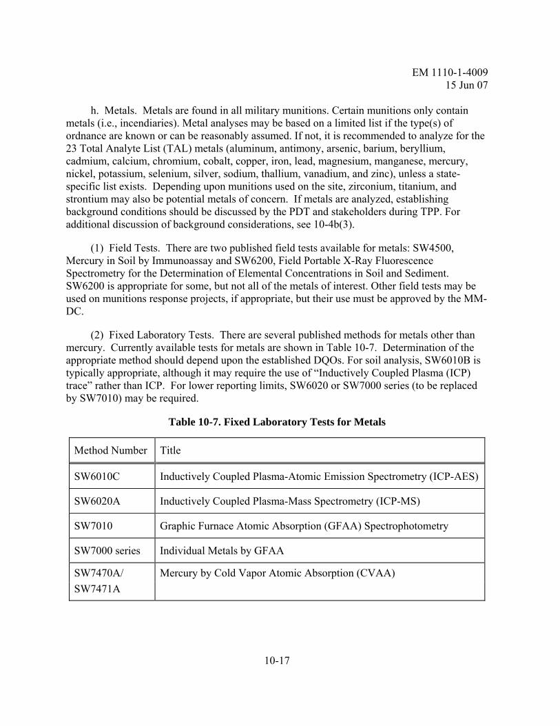
EM 1110-1-4009 15 Jun 07
10-17
h. Metals. Metals are found in all military munitions. Certain munitions only contain metals (i.e., incendiaries). Metal analyses may be based on a limited list if the type(s) of ordnance are known or can be reasonably assumed. If not, it is recommended to analyze for the 23 Total Analyte List (TAL) metals (aluminum, antimony, arsenic, barium, beryllium, cadmium, calcium, chromium, cobalt, copper, iron, lead, magnesium, manganese, mercury, nickel, potassium, selenium, silver, sodium, thallium, vanadium, and zinc), unless a state-specific list exists. Depending upon munitions used on the site, zirconium, titanium, and strontium may also be potential metals of concern. If metals are analyzed, establishing background conditions should be discussed by the PDT and stakeholders during TPP. For additional discussion of background considerations, see 10-4b(3).
(1) Field Tests. There are two published field tests available for metals: SW4500, Mercury in Soil by Immunoassay and SW6200, Field Portable X-Ray Fluorescence Spectrometry for the Determination of Elemental Concentrations in Soil and Sediment. SW6200 is appropriate for some, but not all of the metals of interest. Other field tests may be used on munitions response projects, if appropriate, but their use must be approved by the MM-DC.
(2) Fixed Laboratory Tests. There are several published methods for metals other than mercury. Currently available tests for metals are shown in Table 10-7. Determination of the appropriate method should depend upon the established DQOs. For soil analysis, SW6010B is typically appropriate, although it may require the use of “Inductively Coupled Plasma (ICP) trace” rather than ICP. For lower reporting limits, SW6020 or SW7000 series (to be replaced by SW7010) may be required.
Table 10-7. Fixed Laboratory Tests for Metals
Method Number Title
SW6010C Inductively Coupled Plasma-Atomic Emission Spectrometry (ICP-AES)
SW6020A Inductively Coupled Plasma-Mass Spectrometry (ICP-MS)
SW7010 Graphic Furnace Atomic Absorption (GFAA) Spectrophotometry
SW7000 series Individual Metals by GFAA
SW7470A/ Mercury by Cold Vapor Atomic Absorption (CVAA) SW7471A

EM 1110-1-4009 15 Jun 07
10-18
(3) Small arms-specific Considerations. There has been a considerable amount of study performed at small arms ranges. These studies have focuses on where the contamination is likely to be and on how best to measure it. One key aspect to characterizing soils at a small arms range is reaching consensus on whether to sieve the soil samples prior to analysis. One of the primary reasons to sieve is to remove bullet fragments. Retaining bullet fragments would yield a higher concentration of lead; however, the lead in the fragments would not be readily available to receptors. This subject is recommended for discussion at project TPP sessions. If additional sample preparation is planned, it should be thoroughly described in project work plans. Prior to conducting site characterization or remediation at small arms ranges, review of the following publications is recommended.
(a) Army Environmental Center (AEC) software/documentation for small arms ranges, available through AEC:
• “REST” (Range Evaluation Software Tool)
• “ASAP” (Army Sampling and Analysis Plan)
(b) ITRC Guidance: Characterization and Remediation of Soils at Closed Small Arms Firing Ranges, available at http://www.itrcweb.org/Documents/SMART-1.pdf
(c) EPA Region 2 Guidance: Best Management Practices for Lead at Outdoor Shooting Ranges, available at http://www.epa.gov/region02/waste/leadshot/
(d) TRW Recommendations for Performing Human Health Risk Analysis on Small Arms Shooting Ranges (OSWER #9285.7-37), available at http://www.epa.gov/superfund/programs/lead/products/firing.pdf
10-6. Sampling and Analysis Plan (SAP). Prior to initiating field activities, a SAP should be prepared. The SAP may be a stand-alone document or be an appendix of the Work Plan. It describes the project requirements for all sampling and analysis activities that should take place during a munitions response project. The SAP must consist of the Field Sampling Plan (FSP) and Quality Assurance Project Plan (QAPP) when sampling for MC as required by ER 200-3-1. A SAP Review Checklist is provided in Appendix J of EM 200-1-3.
a. SAP Requirements. The SAP should:
(1) Address each requirement as identified in ER 1110-1-263.
(2) Be prepared in accordance with (IAW) EM 200-1-3.

EM 1110-1-4009 15 Jun 07
10-19
(a) Additional reference material on QAPPs may be found in the Intergovernmental Data Quality Task Force Uniform Federal Policy for QAPPs – QAPP Manual, located at http://www.epa.gov/fedfac/documents/qualityassurance.htm
(3) Include the laboratory Quality Assurance/Quality Control (QA/QC) plan and applicable Standard Operating Procedures as an appendix (Compact Disk (CD) submittal preferred).
(4) Clearly identify any DoD QSM requirements that a laboratory cannot meet.
(5) Document DoD QSM self declaration of compliance
b. Previously prepared Work Plans for the project property should be used as much as possible in the preparation of the SAP. As a minimum, the level of data quality and QC requirements should be equivalent to what is required in the existing Work Plans with the addition of any new requirements that have been added to improve the defensibility of the data quality since the last work plan submittal.
c. The laboratory must meet all of the requirements specified in the DoD QSM, unless approved in advance in the SAP. As noted above, the requirement for the laboratory to provide quantitative second column confirmation for explosives per DoD QSM/EM 200-1-3/SW8000C should not be waived.
d. SAP Review and Approval. The SAP should be submitted to the Life Cycle Project Manager (LCPM) at the FUDS Geographic District and the MM DC. The MM DC should route the plan to the appropriate MM DC technical staff for review, comment, and approval. For FUDS, SAPs must be submitted to the lead regulatory agency for notice and opportunity to comment IAW ER 200-1-3. For other projects, this is recommended also. Once approved by the CO, the SAP represents the standard to which all sampling and analysis activities will be compared to assure compliance for the project.
10-7. Data Interpretation, Validation, Reporting, and Decision Making.
a. Data Interpretation. After a project property undergoes sampling and analysis, it is necessary to carefully interpret all data and determine if project objectives have been met. Project related information such as possible MEC composition (if available) and donor explosive composition should be provided as part of data interpretation. If numeric DQOs, such as screening levels, have been identified for the project, a comparison of those DQOs must take place. Environmental Data Management System (EDMS) software is available to USACE personnel and contractors for DQO comparison. Data gaps may exist and should be identified and explained. Data gaps may require additional action as part of the remedial response.

EM 1110-1-4009 15 Jun 07
10-20
b. Data Review. The contractor should perform data review according to their approved SAP requirements. Review procedures should be based on EM 200-1-10, Guidance for Evaluating Performance-Based Chemical Data; the latest versions of the CLP National Functional Guidelines (EPA 540-R-99-008 and EPA 540-R-04-004, available at http://www.epa.gov/oerrpage/superfund/programs/clp/guidance.htm); and any applicable state or regional requirements. During TPP, the amount of review should be coordinated with regulatory agencies. The review should be documented in the draft and final engineering reports. Review documentation should address review of laboratory and field QC results. Persons performing the data validation should have appropriate experience as determined by their contractual requirements.
c. Data Reporting. Laboratories and contractors each have data reporting responsibilities.
(1) Laboratories must provide data reporting elements for definitive data IAW DoD QSM Appendix DoD-A – Reporting Requirements”. They should report all analytical results greater than the Method Detection Limit (MDL) that, in the analyst’s professional judgment, are believed to be reliably detected. Concentrations reported between the MDL and the Practical Quantitation Limit (PQL) must be flagged as estimated. PQLs must be at least 3 times MDLs for all analytes, as required by the DoD QSM. Non-detect results should be reported to the PQL unless the laboratory has demonstrated the ability to report non-detects to smaller concentrations by means such as detection limit check samples. Data packages should be organized and assembled such that the analytical results are reported on a per-batch basis.
(2) Contractors should submit the complete data packages to the MM DC and reference them as part of the large study report. They should include the analytical data in the draft and final engineering reports in tabular data summary table format. There should be, at a minimum, two types of data summary tables. The first should include all analytical results for all samples collected. The second should include all analytical results greater than the MDL for all samples collected. Both tables should include for each analyte, medium of concern, and study area, the decision limits (e.g., risk based screening limits and background thresholds, if any), the MDL, the reporting limit for non-detects, and the PQL (if different from the reporting limit for non-detections). Both tables should be sorted by sample field ID, method, analyte, and include appropriate data flags resulting from laboratory review and contractor’s data validation. Results on all tables should be reported with an appropriate number of significant figures, e.g., J-qualified results below the PQL should be reported to one significant figure. If there are PQLs that exceed the applicable decision limit, these should be annotated.
(3) The analytical data should also be provided electronically to the MM DC by the Contractor in the Staged Electronic Data Deliverable (SEDD) format for all FUDS projects. The SEDD stage and specification version required should be stated in project Statements of Work (SOWs)/Performance Work Statements (PWSs). Other project-specific Electronic Data Deliverable requirements should be documented in project SOWs/PWSs. For more

EM 1110-1-4009 15 Jun 07
10-21
information on the SEDD format, see http://www.epa.gov/superfund/programs/clp/sedd.htm. The SEDD formatted deliverable can be evaluated by the Automated Data Review (ADR) software. ADR software is intended to automate certain data review functions that are strictly comparisons to numeric criteria (i.e., holding time compliance, comparison to recovery/relative percent difference limits, etc.) Use of the ADR software will require that the contractor develop a comprehensive library file for all of the methods to be analyzed under the SOW/PWS. The library file should accurately reflect all of the analytical quality requirements as documented in the final SAP for the project and should be provided to both MM DC and the subcontract lab for use in screening Electronic Data Deliverable (EDD) submittals. The electronic deliverable must include appropriate data flags resulting from laboratory review and contractor’s data validation. All electronic data submitted by the contract laboratory is required to be error-free, and in complete agreement with the hardcopy data. Data files are to be delivered IAW contract requirements. They should be submitted with a transmittal letter from the laboratory that certifies that the file is in agreement with hardcopy data reports and has been found to be free of errors using the latest version of ADR evaluation software provided to the laboratory. The contract laboratory, at their cost, should correct any errors identified by MM DC. The contractor is responsible for the successful electronic transmission of field and laboratory data. The laboratory is responsible for archiving the electronic raw data, associated software, and sufficient associated hardcopy data (e.g., sample login sheets and sample preparation log sheets) to completely reconstruct the analyses that were performed for the period specified after completion of the applicable contract. If no period is specified, laboratories should keep data for 10 years.
d. Decision Making. The sampling and analysis data and evaluations are usually incorporated into a larger study (e.g., SI, Engineering Evaluation/Cost Analysis (EE/CA), RI/FS, Site Characterization, etc.) and the USACE PDT, contractors, and project stakeholders are involved in making decisions regarding future work to be performed.
10-8. Quality Management.
a. Data Quality. The contractor must provide data quality of a level sufficient to support the project’s objectives as defined in the SAP. The contractor must provide QC of the various analytical tasks performed. The contractor is responsible for achieving data quality as defined in the SAP. Analytical data that does not meet QC requirements may be rejected by the government. Re-sampling and re-analysis may be required, with contract type determining whether there are additional costs to the government.
b. Quality Control. It is recommended that field duplicates be collected. The PDT should determine the rate per matrix per analysis per sampling event. Each project sample designated for a field duplicate must be homogenized thoroughly, and then divided equally (if sampling and analysis of volatile organic compounds is required for an MC site, the duplicate should be collocated). Both portions should be sent to the contractor’s laboratory, but the

EM 1110-1-4009 15 Jun 07
10-22
identity of the duplicate should not be provided to the laboratory. The QC samples should include all sample matrices and analytical parameters except disposal parameters (i.e., Toxicity Characteristic Leaching Procedures (TCLP), reactivity, corrosivity, and ignitability). The contractor should administer all QC sample handling and custody requirements in a similar manner to that used for the environmental samples.
c. Coordination with QA Laboratory. If contractual requirements include collection of QA samples, the contractor must provide coordination and QA samples (collected and transported by the contractor) to the QA laboratory identified in the SOW/PWS. The PDT should determine the rate per matrix per analysis per sampling event for the QA splits. The contractor should provide sample containers, shipping, etc. for QA samples. QA samples should be taken as splits of the same samples as QC duplicates (i.e., sample should be homogenized and split in triplicate) (if sampling and analysis of volatile organic compounds is required for an MC site, the QA split should be collocated). The QA split samples should include the same matrices and parameters as QC duplicate samples. The QA laboratory should be provided a list of measurement quality objectives (MQOs). The MQOs should include, but should not be limited to, identification of extraction and analysis method numbers and a list of analytes with required limits. All QA sample handling and custody requirements should be administered by the contractor similar to the environmental samples. The QA samples should be sent to the QA Laboratory by overnight delivery for government contract compliance monitoring. See EM 200-1-6 for additional guidance.

EM 1110-1-4009 15 Jun 07
11-1
CHAPTER 11 BLAST AND FRAGMENT PROTECTION
11-1. Introduction.
a. This chapter describes the blast and fragment protection requirements for unintentional and intentional detonations. These requirements should be addressed by the PDT when planning and conducting a munitions response. A checklist of planning considerations has been provided as Table B-8.
b. The MSD calculated to perform work at an MRA may include the MSD for unintentional detonations, intentional detonations, or both depending on the SOW. Preliminary site work performed at an MRA, such as surveying, laying out search lanes, and non-intrusive geophysical investigations, do not require the establishment of a MSD. The MSD requirements for intentional and unintentional detonations are discussed in paragraph 11-5.
11-2. DQOs. When evaluating the blast and fragment protection components of a munitions response project, the PDT should consider DQOs in the following areas:
a. Establishing MSDs IAW DOD 6055.9-STD.
b. Proper design and approval of any required engineering controls.
c. Procedures for reviewing government and contractor planning documentation.
11-3. Explosives Safety Considerations.
a. General. When developing the SOW for a munitions response project, the PDT will need to evaluate several resources to find information relating to the current characteristics of the project property, the type of munitions response project being proposed, the historical use of the project property, and the nature of the military munitions that were used at the location. These resources may include:
(1) INPR.
(2) SI Report.
(3) Historical records relating to the operation of the installation.
(4) Previous site investigation reports.

EM 1110-1-4009 15 Jun 07
11-2
(5) Other historical or investigative reports that may give an indication of the current state of the project property.
b. Specific site characteristics that should be examined when reviewing these reports include:
(1) Project property layout.
(2) Land use of the project property and the surrounding area.
(3) Physical characteristics of the project property (e.g., topography, vegetation).
(4) Man-made structures at the project property (e.g., buildings, roads).
(5) Type of MEC present or suspected to be present.
c. Munitions Response. The type of munitions response proposed for a project property will influence the type and amount of blast and fragment protection requirements for a project. The PDT will need to consider the type of munitions response being proposed for the project property, such as:
(1) Anomaly Avoidance.
(2) Construction Support.
(3) RI or EE/CA.
(4) Remedial/Removal Action.
d. Probable Military Munitions Characteristics. The PDT will need to consider the type of MEC that could potentially be found at the project property. This information may be obtained from any archival information available on the project property or from any other reports that have previously been generated. Some of the elements to be considered in this category include:
(1) Conventional versus chemical MEC.
(2) MEC versus munition debris.
(3) The type and amount of MEC anticipated.
(4) The potential age, condition, and burial depth of MEC.
EM 1110-1-4009 15 Jun 07
11-3
(5) The potential fuzing of the MEC.
e. MGFD. For all MRAs and MRSs, an MGFD will be determined. The MGFD is the munition that has the greatest fragmentation distance of the MEC items that are reasonably expected to be found at the MRA or MRS, based on research or site characterization. The PDT should select the correct MGFD for the project property based on the available historical information such as that listed in paragraph 11-3a.
f. Explosive Soils. For explosive soils, the MGFD concept does not apply. Instead, the concept of Maximum Credible Event (MCE) applies. For soil, the MCE is the concentration of explosives times the weight of the mix. For example, 1,000 pounds of soils containing 15 percent Trinitrotoluene (TNT) has an MCE of 150 pounds. When the concentration varies within the area, weighted averages or any other valid mathematical technique can be used, as long as the technique is explained and technically supported in the submission. Overpressure and soil ejecta radius will be considered when determining the Q-D for explosive soils. For additional information on explosive soils, contact the MM CX .
11-4. Explosive Effects.
a. A major component of the MM CX’s involvement during a munitions response project is the calculation of MSDs for unintentional and intentional detonations of MEC items. A review of the explosive effect calculations that should be used by the PDT in the determination of MSDs is provided in this paragraph. This paragraph also provides the source documentation for these MSD calculations.
b. There are six factors of a MEC detonation that should be considered by the PDT when either siting an area for intentional MEC detonations (such as when setting up an OB/OD area) or when the possibility exists of an unintentional detonation during the course of a munitions response investigation. These six factors include:
(1) Fragmentation.
(2) Overpressure.
(3) Thermal flux.
(4) Ground shock.
(5) Noise.
(6) Ejected soil.

EM 1110-1-4009 15 Jun 07
11-4
c. Controlling Factors. To determine the appropriate MSD, the PDT should use the explosion effect calculation that yields the greatest MSD, unless an engineering control will be used to limit the explosion effect. Typically, either fragmentation or overpressure is the controlling factor in determining the necessary MSD. However, thermal flux and soil ejecta may become controlling factors if a buried detonation is planned, as discussed in paragraph 11-4d.
(1) Fragmentation. The method to be used to determine the separation distances due to fragmentation is identified in DDESB Technical Paper (TP) 16. This TP contains the methodology of calculations for determining fragmentation distances for many of the MEC items that have been encountered on past and present USACE project sites. These specific distances should be used for those specific MEC types in lieu of DOD 6055.9-STD. TP 16 also includes tables and charts to be used for determining the fragmentation distances when the item is unknown. Generally speaking, the maximum horizontal fragmentation distance is to be used for all unexploded ordnance (UXO) items as the MSD for all non-essential personnel for both intentional and unintentional detonations. This distance may be lessened when using authorized fragmentation reducing engineering controls, see DDESB TP 15 for a listing of all approved engineering controls for this purpose. All personnel will be located outside of the maximum horizontal fragmentation distance when intentional detonations are taking place. For MEC items, other than UXO, the use of the hazardous fragmentation distance (HFD) may be authorized during activities that may produce an unintentional detonation. The OE-CX will provide assistance to the USACE districts in determining when this is permissibile.
(2) Overpressure. The method to be used by the PDT in determining the MSD for overpressure is the same for both unintentional and intentional detonations. In both circumstances, the equation D=KW1/3 is used. However, the safety factor ‘K’ differs depending on whether the circumstance is an unintentional or intentional detonation. For unintentional detonations a K value of 50 should be used, while for intentional detonations a K value of 328 should be applied. Generally speaking, the overpressure factor is used when the MEC item identified for the project site does not have a fragment producing effect, e.g., some practice bombs and munitions use black powder as signal indicator and the design of the MEC is to produce a visual effect such as a puff of smoke or a large sound report to enable the firing crew to see where the munition hit or landed. These types of munitions will usually use the K328 factor when determining the MSDs for the site activities. Normally the net explosive weight of the donor charge will be added to explosive weight of the MEC item to come up with a total explosive weight when figuring the K328 factor.
d. Secondary Factors. The following secondary factors are considered in calculating MSDs. These factors are typically not controlling factors in MSD determinations.
(1) Thermal Flux. Thermal flux will rarely be a controlling factor in MSD determinations. However, in some instances, the thermal flux generated from the exothermic
EM 1110-1-4009 15 Jun 07
11-5
reactions that result from the detonation of certain MEC may generate a MSD greater than either the fragmentation or overpressure distance. The PDT should use the same method for determining the MSD based on thermal considerations for both unintentional and intentional detonations. The PDT should use the standards listed in DOD 6055.9-STD to determine the MSD due to thermal flux. If the MSD due to thermal flux listed in DOD 6055.9-STD cannot be met, then shields complying with MIL-STD-398 should be used to provide an acceptable level of thermal protection.
(2) Ejected Soil. The PDT should reference DDESB TP 16 to calculate the distance that soil may be ejected as a result of an intentional detonation. In addition to the hazards posed by ejected soil during a subsurface MEC detonation, the burial depth calculation may also assist in determining the amount of earth cover necessary to defeat the fragmentation generated during a MEC detonation. A computer model has been created to assist in determining the amount of earth cover necessary to mitigate the fragmentation hazard from a MEC detonation. The PDT should reference HNC-ED-CS-S-97-7, Revision 1, for additional details on the use of this computer model.
(3) Ground Shock. The PDT should use the same method for determining the MSD based on ground shock for both unintentional and intentional detonations. In those areas where vibration damage may occur due to a MEC detonation, the PDT should consult the requirements listed in TM 5-1300. In addition, state and local regulations may exist that are more stringent than the Federal regulations. As a result, local regulators should be contacted during the planning process to determine the level of ground shock allowed according to any local codes.
(4) Noise. The PDT should use the same method for determining the MSD based on noise for both unintentional and intentional detonations. The PDT should use the criteria presented in DA Pam 385-64. In addition, state and local regulators should be contacted during the planning process to determine if there are more stringent local regulations in regards to noise generated as a result of a MEC detonation.
11-5. MSDs.
a. The PDT should ensure the appropriate MSDs are used, as identified in DDESB TP 16 and DOD 6055.9-STD.

EM 1110-1-4009 15 Jun 07
11-6
11-6. Unintentional Versus Intentional Detonation Minimum Separation Criteria. When the PDT or the UXO contractor determines the MSD to be used on a munitions response project, two sets of MSD criteria may need to be considered.
a. The first set of criteria has been established for unintentional detonations. An unintentional detonation is a detonation that is not planned in advance. Unintentional detonations are discussed in paragraph 11-7.
b. The second set of criteria has been established for intentional detonations of MEC. An intentional detonation is a planned, controlled detonation. Intentional detonations are discussed in paragraph 11-8.
11-7. Unintentional Detonations.
a. The MSD for unintentional detonations is the distance non-project personnel must maintain from intrusive operations, and they are:
(1) For UXO items, it is the maximum horizontal fragment distance, as identified in DDESB 16, for fragment producing munitions.
(2) For other MEC items that produce fragments, it may be permissible to use the hazardous fragment distance (HFD), contact the OE-CX for additional information.
(3) For MEC items that do not produce fragments (by design), but contain explosives, use the K328 distance of the item.
b. These distances may be reduced by using approved engineering controls.
c. Team Separation Distance (TSD). The TSD is the greater distance of:
(1) Overpressure value of K50, or
(2) 200 feet.
11-8. Intentional Detonations. The MSD for intentional detonations is the distance that both project personnel and the public will be from the intentional detonation. The MSD for intentional detonations is calculated by taking the greatest value of the following:
a. Overpressure at K value of 328. Ensure the explosive weight of the donor charge is added to the net explosive weight of the MEC item when making this calculation.

EM 1110-1-4009 15 Jun 07
11-7
b. Maximum horizontal fragmentation distance as determined IAW DDESB TP 16, unless engineering controls are being employed. The item having the greatest fragment distance will become the MGFD for intentional detonations for a MRS.
11-9. Explosives Siting Plan.
a. General.
(1) The proposed MSDs for unintentional detonations, intentional detonations, and siting of critical project components are discussed in the Explosives Siting Plan, a component of the project Work Plan. The Explosives Siting Plan will be reviewed by the PDT to ensure that the appropriate minimum separation standards have been applied. The PDT should review the Explosives Siting Plan to ensure that it properly describes the MSDs and other safety criteria that will be employed during a munitions response. All ESPs must be reviewed and approved by the OE-CX, as delegated by HQUSACE. The OE-CX will provide the MACOM/Direct Reporting Unit (DRU) approval in accordance with the delegation authority. DOD 6055.9-STD requires all explosive safety plans to have a MACOM/DRU approval. The following explosives operations will be described in the plan and located on a map:
(a) MRSs.
(b) Explosives storage magazines.
(c) Planned or established demolition areas.
(2) The site map should be scaled at 1-inch equals 400 feet. However, a larger scale may be used if available and the map can be logistically included in the work plan. Also, a smaller scale is acceptable as long as the distances can be shown accurately. If an unscaled map is used, all relevant distances will be labeled.
(3) The MSDs calculated for the operation should be discussed in the text of the plan and Q-D arcs for the above-listed project elements drawn on the map.
b. Explosive Safety Quantity-Distance (ESQD) Requirements. DOD 6055.9-STD provides many tables, in Chapter 9, on this topic. Explosive Storage QD for the BATF Type II magazines, used predominantly on USACE MMRP locations, is normally derived from Table C9.T2 for hazard division (HD) 1.1 explosives. Select the Net Explosive Weight (NEW) you want to store, look to the right in the "Structure" column and that will be your ESQD arcs around your potential exposure site (PES) for, non-fragmenting, bulk high explosives or non-fragmenting MEC. If recovered, fragmenting MEC is being stored pending disposal, you must site the magazine using the same table but use the "Open" column distances. See DOD 6055.9-

EM 1110-1-4009 15 Jun 07
11-8
STD for other storage configurations and PESs.If the PDT is going to establish an OB/OD area within the MRS, the provisions of EP 1110-1-17 apply.
c. MRSs. The PDT should confirm that the MSDs during intrusive operations are determined IAW the criteria discussed in paragraphs 11-7 and 11-8.
d. Explosives Storage Magazines. The PDT should ensure that the following items are discussed in the Explosives Siting Plan in regards to the Explosives Storage Magazine:
(1) Type of explosives storage magazine, (e.g., portable commercial, above ground, shed, and earth-covered).
(2) NEW and hazard division to be stored in each magazine, (generally, recovered MEC is considered to be Hazard Division 1.1).
(3) Q-D criteria used to site the magazine.
(4) Design criteria for any proposed engineering controls if the Q-D criteria cannot be met.
(5) Designation of commercial explosives into a DOD Hazard Classification and Storage Compatibility Group by USATCES prior to being stored in a DOD facility. (See DA Pam 385-64 for procedure.)
(6) Lightning Protection.
(a) FUDS. Lightning protection is not required if the following criteria are met:
• The magazine is constructed of metal that is 3/16-inch steel or larger (reference Appendix L of National Fire Protection Association 780).
• The magazine is grounded (see Figure 11-1).
• The magazine is located at least 6-1/2 feet from the nearest fence.
• The grounding system will be inspected and tested IAW the requirements of DA Pam 385-64.
(b) BRAC and Active Installations. Lightning protection for BRAC and active installations will meet the appropriate requirements identified in the service regulations.

EM 1110-1-4009 15 Jun 07
11-9
Figure 11-1. Magazine Grounding Detail

EM 1110-1-4009 15 Jun 07
11-10
e. Planned or Established Demolition Areas. The PDT should confirm that the MSDs are established IAW the provisions of this chapter (this document).
f. The contained detonation chamber will have a DDESB-approved siting plan prior to operation at an MRA.
g. Footprint Areas. The PDT will ensure that the following footprint areas are addressed in the Explosives Siting Plan. These areas, however, do not have to be shown on the map:
(1) Blow-in-Place Areas. MSDs for all personnel should be determined using the requirements for intentional detonations discussed in paragraph 11-7.
(2) Collection Points. Collection points, if used, should have the same MSD as that identified for unintentional detonations, as discussed in paragraph 11-8.
(3) In-Grid Consolidated Shots. MSDs for all personnel should be determined using the requirements for intentional detonations, as discussed in DOD 6055.9-STD. The procedures for in-grid consolidated shots are presented in the USAESCH document titled Procedures for Demolition of Multiple Rounds (Consolidated Shots) on Ordnance and Explosives Sites. This document and the corresponding DDESB approval letter will be available on-site.
11-10. Engineering Controls. Engineering controls are used to mitigate the effects of unintentional or intentional explosions if the calculated MSD for the MEC to be destroyed cannot be met. The primary goals of using engineering controls are to improve personnel safety and/or to reduce the exclusion zone. This section discusses engineering controls that can be used by the PDT for either an unintentional or intentional explosion scenario. DDESB TP 15 contains a listing of the approved engineering controls that can be used on USACE MMRP locations.
a. Engineering Controls for Unintentional Detonations. Engineering controls used for unintentional detonations include various barricades. The PDT should design barricades IAW approved DOD standards. To implement a barricade that has been previously-approved by DDESB, the PDT should contact the MM CX. If a barricade has not been previously approved, a complete structural design package will be submitted to the MM CX as part of the Explosives Siting Plan/ESS. The structural design package will include design drawings, design details, calculations, drawings, and relevant testing details. The design will show how fragmentation is captured and overpressure is reduced. The design package, as part of the Explosives Siting Plan/ESS, is forwarded through appropriate channels to DDESB for approval.
b. Engineering Controls for Intentional Detonations. The most common engineering controls used during intentional detonations are either soil cover or sandbags. If controls are

EM 1110-1-4009 15 Jun 07
11-11
required for intentional explosions, the MM DC should be contacted to arrange for the preparation of a design (or the review of a design already prepared) with the MM CX.
(1) Soil Cover. If soil is proposed to be used over a to-be-detonated MEC item, the PDT may use one of several computerized models to determine the required thickness of soil cover necessary for the intentional detonation of MEC (see 8-5d(2)). The Buried Explosion Module is one such computerized model. The methodology used in this software is documented in HNC-ED-CS-S-97-7, Revision 1 and DDESB TP 16. The use of soil as an engineering control reduces the fragment and soil ejecta distances.
(2) Sandbags. Sandbags may be used for MEC no larger than 155 mm. If sandbags are proposed to be used as an engineering control to mitigate the fragmentation and overpressures generated during an intentional MEC detonation, the PDT should refer to HNC-ED-CS-S-98-7.
(3) Barricades. There are a number of approved barricades that may be used for the mitigation of fragments, such as the open front barricade, enclosed barricade, and the miniature open front barricade. A comparison, siting, and selection procedure for various barricades can be found in HNC-ED-CS-S-96-8, Revision 1.
(4) Water Barriers. In some instances it may be necessary to use water as a mitigating agent for the control of blast effect and fragment containment resulting from the intentional detonation of munitions. HNC-ED-CS-S-00-3 contains the requirements necessary when using water as a mitigating agent.
(5) Contained Detonation Chambers. Another engineering control that may be proposed for the intentional detonation of MEC is a Contained Detonation Chamber (CDC). CDCs are designed to capture all fragmentation from the detonated MEC and will be approved by DDESB for the intentional detonation of MEC.

EM 1110-1-4009 15 Jun 07
11-12
This page intentionally left blank

EM 1110-1-4009 15 Jun 07
12-1
CHAPTER 12 RISK CHARACTERIZATION
12-1. Introduction.
a. This chapter describes risk characterization for MMRP and is limited to risk from MEC. A risk assessment is used to describe and estimate the likelihood of adverse outcomes from an encounter with MEC. Several methods exist for performing a MEC risk assessment for MRSs; however, there is no single MEC risk assessment methodology that is applicable to a variety of MRSs that has been widely accepted, tested, and fully implemented.
b. An explosives safety hazard is the probability that MEC might detonate and potentially cause harm as a result of human activities. An explosives safety hazard exists if a person can come near to or into contact with MEC and then energy of some sort is applied to it to cause it to detonate. The energy could be applied by the person, by external forces not associated with the person’s contact, or an internal mechanism within the MEC item itself.
c. Most MEC risk assessments will concentrate on the explosive hazards associated with MEC. However, there may also be a risk associated with the presence of MCs. This risk would be characterized IAW with the procedures used to assess HTRW risk; which may include an assessment of both human and ecoreceptors. See EM 200-1-4 for additional guidance on HTRW risk process.
12-2. CSM. The CSM is used to communicate and describe the current state of knowledge and assumptions about the MEC risk at a project property. The CSM presents the exposure pathway analysis by integrating information on the MEC source, receptors, and receptor/MEC interaction. See EM 1110-1-1200 for additional guidance.
12-3. MEC Risk Pathway.
a. The potential for an explosives safety hazard depends upon the presence of three critical elements to complete the risk pathway. If any one of these three elements is missing, there is no completed pathway and, therefore, no resulting MEC risk. Each of the three elements also provides a basis for implementing effective risk management response actions. The three critical elements include:
(1) A source of MEC (or the presence of MEC).
(2) A receptor or person.
(3) The potential for interaction between the source and the receptor (such as picking up the item or disturbing the item by plowing).

EM 1110-1-4009 15 Jun 07
12-2
b. Source of MEC.
(1) The factors affecting risk associated with the MEC source are the quantity or density of the MEC. The more MEC present at a project property, the greater the likelihood for an interaction between a receptor and MEC. If there is no MEC present, there is no completed pathway and, consequently, no explosives safety hazard.
(2) At military training facilities, it was customary to conduct training exercises using practice munitions, including those ranges designated for use of High Explosive- (HE-) filled munitions. Only after troops demonstrated proficiency in firing tactics were troops allowed to use HE-filled munitions. As a result, training ranges contain a preponderance of practice munitions.
(3) The primary release mechanisms resulting in the occurrence of MEC are related to the type of military munition activity, or result from the improper functioning of the military munition. For example when a military munition (HE artillery shell) is fired it will do one of three things:
(a) It will detonate completely. This is called a high order detonation.
(b) It will undergo incomplete detonation. This is called a low order detonation.
(c) It will fail to function. This results in UXO.
(4) Military munitions may be lost, abandoned, or buried, resulting in unfired munitions that could be fuzed or unfuzed.
(5) In addition there are military munitions that will have a delayed function and may be hidden by design resulting in a deployed, armed, and fuzed muntion.
(6) Military munitions demilitarization through OB/OD is used to destroy excess, obsolete, or unserviceable munitions by combustion (OB) or by detonation (OD). An OD operation can result in a high order detonation or a low order detonation. In addition, the munitions may possibly be spread beyond the immediate vicinity by the detonation (“kick-outs”). Incomplete combustion or low/high order detonation failure can leave uncombusted explosives.
c. Receptor. Receptors are people that have the potential to contact MEC. The factors affecting risk associated with the receptor include the number of people that access the area containing MEC and the accessibility of the property containing MEC. The more receptors that use the location and the easier it is to access the property, the greater the potential for MEC contact. The converse is also true: the fewer the people that are present and the harder it is to

EM 1110-1-4009 15 Jun 07
12-3
access the property due to man-made or natural barriers, the lower the potential for MEC contact.
d. Interaction. The factors affecting risk that are associated with the interaction with the MEC include: MEC contact potential; energy application; and MEC sensitivity and potential severity.
(1) The MEC contact potential is affected by: the depth of the MEC; site stability (erosion); and the depth and type of receptor activity. For instance if the project property is unstable there is a greater likelihood the MEC will be brought closer to the surface and increase the potential for interaction. Also the greater the depth of intrusion by the receptor the greater likelihood there will be receptor and MEC interaction.
(2) The energy application factor affects the likelihood that a receptor will apply enough energy to a MEC item causing it to function. The risk to the receptor increases greatly the more energy is applied to a MEC. Examples include an item is picked up, hit with a hammer, thrown in a fire, etc. However, there may also be the case where the type of MEC requires no force be applied to it by the receptor in order to function.
(3) Sensitivity and Severity.
(a) The greater the sensitivity, the greater the likelihood for a MEC item to function. The type of MEC affects the likelihood and severity of injury if a MEC functions. The hazard from MEC typically results from a single interaction between a receptor and a MEC source and may have one of three outcomes: no effect, injury, or death. The consequence of a military munitions detonation is associated with physical forces resulting from blast pressure, fragmentation hazards, thermal hazards and shock hazards. The type of hazard threat and the severity of the hazard depend on the type of MEC.
(b) Different types of military munitions vary in their likelihood of detonation and their potential for harm. The classification of energetic materials used in military munitions can be divided by their primary uses: explosives, propellants, and pyrotechnics. Explosives and propellants, if properly initiated, will evolve into large volumes of gas over a short period of time. The key difference between explosives and propellants is the reaction rate. Explosives react rapidly, creating a high-pressure shock wave and are designed to break apart a munitions casing and cause injury. Propellants react at a slower rate, creating a sustained lower pressure. Propellants are designed to provide energy to deliver a munition to its target. Pyrotechnics produce heat, but less gas than explosives or propellants. Pyrotechnics are used to send signals, to illuminate areas, simulate other weapons during training, and are used as ignition elements for certain weapons. When initiated, pyrotechnics produce heat, noise, smoke, light or infrared radiation. Incendiaries are a class of pyrotechnics that are highly flammable and are used to destroy a target by fire.

EM 1110-1-4009 15 Jun 07
12-4
(c) Explosives can be further subdivided into low explosive and high explosive based on the velocity of the explosion. When a HE munition is initiated, it decomposes almost instantaneously and the detonation can be lethal. Low explosives undergo decomposition or combustion at rates from a few centimeters per minute to approximately 400 meters per second (EPA, 2002). Black powder is a common low explosive and when used as a spotting charge it can cause injury or burns. In a 37mm projectile, the black powder is fully encased and can be lethal if initiated.
(d) Some practice munitions contain an energetic, (low explosive or pyrotechnic charge) and include a fully functional fuzing system, while other practice munitions are wholly inert. A practice munition poses less of a hazard than an HE-filled UXO item. The hazard from a practice munition may result from a fuze or spotting charge contained in the munition in order to produce a flash or smoke upon impact. Unexpended spotting charges may cause a flesh burn. The wholly inert practice items have no explosive parts, including fuze components, and do not pose an explosive safety hazard.
12-4. Risk Management Principles.
a. Risk management consists of a two-part response, those munitions response actions that remove the hazard such as physical removals and those munitions response actions that manage the residual hazards such as land use controls (LUCs). Physical removal involves reducing the quantity of MEC at the property, which directly lowers the risk. However, there frequently is residual risk at MRAs since it is technically and financially impracticable to provide 100 percent removal of all items. However, LUCs can be used to effectively manage the residual risk.
b. LUCs are an important component of the overall risk management strategy. LUCs may consist of educational awareness programs, legal restrictions on land use, and physical access controls. See EP 1110-1-24 for procedural information on establishing and maintaining land use controls. The educational awareness program should be the cornerstone of the LUC program because of the paramount importance of effective risk communication. Controlling or altering the behavior of receptors can reduce the potential for interaction with MEC and reduce the risk. Defense Environmental Network & Information Exchange provides an Internet web-based Educational Program, available at https://www.denix.osd.mil/denix/Public/Library/Explosives/UXOSafety/uxosafety.html. LUCs such as access and activity restrictions can also be used to decrease the number of receptors and the potential for interaction with MEC. If you reduce the number of receptors on-site and the activities that cause interaction the risk is reduced.
c. In summary, if there is potential for a completed MEC pathway the following risk management principles can be applied to mitigate the risk:
EM 1110-1-4009 15 Jun 07
12-5
(1) Reducing the quantity of MEC on-site lowers the risk.
(2) Reducing the number of potential receptors on-site lowers the risk.
(3) Reducing the potential for interaction between receptors and MEC lowers the risk.
(4) Modifying or controlling the behavior of the receptors lowers the risk.
12-5. Risk Characterization Methods.
a. Risk characterizations are site-specific evaluations and may vary in both detail and extent to which qualitative and quantitative inputs are used. The risk characterizations depend on the complexity and particular circumstances of the project property, as well as the availability of Applicable or Relevant and Appropriate Requirements and other guidance. The risk characterization should consider the potential risks associated with current land use and activities, as well as reasonably anticipated future land use. Existing site conditions should be evaluated to provide a baseline risk in the absence of any actions to control or mitigate that risk.
b. EPA has developed general risk assessment methods for evaluating human health and environmental risks at HTRW-contaminated locations. These general risk assessment methods are conducted using four basic steps: (1) hazard identification, (2) dose response modeling, (3) exposure assessment, and (4) risk characterization. These methods are typically used to quantify risk from long-term, chronic exposure to low levels of contamination. EPA has no provisions for evaluating explosives safety risk.
c. The risk assessment processes that have been developed for chemical contaminants do not lend themselves to a MEC risk characterization because of the unique properties of the MEC pathway. The MEC pathway, including the potential for human interaction with military munitions, needs to be evaluated differently than processes developed for chemical contaminants.
d. Both quantitative and qualitative methods have been used to evaluate MEC risk. Information on available risk tools can be found on the OE Directorate website. Additional guidance on recommended models can be obtained by contacting the MM CX.
e. The results of the risk characterization should be used to evaluate potential munitions response alternatives. Specifically, risk characterization results can be an input to the evaluation of the Protectiveness of Human Health and the Environment criterion in an EE/CA or RI/FS. The risk characterization is used to communicate the magnitude of the risk at the location and the primary causes of that risk, and to aid in the development, evaluation, and selection of appropriate response alternatives.

EM 1110-1-4009 15 Jun 07
12-6
12-6. Risk Communication.
a. Risk communication is an integral part of risk management. Early, effective communication of risk will allow the public to have a stake in the decisions made and increase the likelihood that the decisions made will be supported by the community. When the public perceives the government as being unresponsive and community relationships are poor, the public will tend to judge the risk as being more serious. Without effective risk communication, the level of risk will have little effect on the public’s perception of risk and increasing the amount of technical detail will have no effect on the perceived risk.
b. Critical to effective risk communication is early stakeholder involvement. Restoration Advisory Boards (RABs) are the cornerstone of public involvement for implementing effective communication. RABs are advisory groups for the environmental restoration process and may involve representatives from the DOD, EPA, state and local governments, tribal governments and the affected local community. Although RABs are not decision-making bodies, the RAB members share community views and enable the continuous flow of information. The PDT should plan to have a risk assessment presentation to the RAB provided by an expert from the MM CX. Additional information on developing a public participation plan can be found in EP 1110-3-8.
c. There are many ways to effect risk communication and because of the differences in the education, interest level, and knowledge of the audience, more than one communication venue may be appropriate. The PDT should consider designating one person as a communications coordinator. This person could be from the public affairs office or a RAB member and does not necessarily have to be a technical expert. The communications coordinator should become knowledgeable about MEC risk assessment issues and know when and where to go for additional expertise. The PDT and communications coordinator should develop at the beginning of a project a site-specific risk communications plan. Components of the plan may utilize different methods of risk communication including presentations, videos, partnering meetings, public information forums, and printed media.

EM 1110-1-4009 15 Jun 07
13-1
CHAPTER 13 QUALITY ASSURANCE SURVEILLANCE PLANS
13-1. Purpose and Overview.
a. This Chapter describes the roles and responsibilities of the Project Delivery Team with regard to development and implementation of the project specific Quality Assurance Surveillance Plan (QASP). A QASP which directly corresponds to a contract’s specified performance standards, is used to measure contractor performance and to ensure that the Government receives the quality of services called for under the contract and pays only for the acceptable levels of services received. Each PDT member has an important part to play to ensure quality products are received from the contractor.
b. ER 5-1-11 requires every project to have a Project Management Plan. As part of the PMP, each USACE element must document its quality policies, procedures, and responsibilities in a Quality Management Plan (QMP). The development of a QASP may satisfy all QMP requirements and should be incorporated into the PMP.
c. Effective QA is comprehensive (i.e., it involves all aspects of the entire life cycle of projects), and:
(1) Ensures people accomplish appropriate tasks at the appropriate time.
(2) Ensures customer objectives and expectations are met or exceeded.
(3) Includes the use of a multidisciplinary team of trained personnel.
(4) Includes using a comprehensive and systematic approach to project planning (e.g., Technical Project Planning).
(5) Includes reviewing project documents and project status.
(6) Includes observing field operations.
13-2. Responsibilities. The responsibilities detailed herein are specific to Formerly Used Defense Site projects and are specific to the QA process. General responsibilities for the safe execution of MMRP projects are detailed in ER 200-3-1 and ER 1110-1-8153.
a. Project Manager.

EM 1110-1-4009 15 Jun 07
13-2
(1) Oversee the development and implementation of the QASP. Specific surveillance activities for project managers will vary depending upon the type of project. Common responsibilities for projects are provided in the QASP template provided in Appendix C.
b. PDT.
(1) Provides technical input to the PM to be included in the QASP.
(2) Implements the QASP as specified in the particular project QASP. Specific QASP responsibilities for the PDT team members will vary depending upon the type of project. Common responsibilities for various PDT members are also provided in the QASP template provided in Appendix C.
(3) Provides the contracting office any specifications for inspection, testing, and other contract quality requirements essential to ensure the integrity of the product or service. For service contracts, like most MMRP contracts, these quality requirements are documented in a QASP.
13-3. QASP Overview.
a. What is a QASP? All service contracts require the development and implementation of a QASP. A QASP describes how government personnel will evaluate and assess contractor performance. The purpose of the QASP is to describe how project performance will be measured and assessed against performance standards. It is based on the premise that the contractor, not the government, is responsible for managing quality control.
b. When is a QASP done? The QASP is intended to measure performance against the standards in the Performance Work Statement (PWS) or Statement of Work. As such, these interdependent documents must be coordinated. Since the PWS/SOW and QASP are intertwined, it is both effective and efficient to write them simultaneously.
c. What should be considered when developing a QASP?
(1) The QASP is a requirement of FAR Part 46.103(a) for service contracts.
(2) The QASP describes the contract technical quality requirements, including inspection and testing requirements.
(3) Preliminary QASPs should be developed for each project in conjunction with the development of the PWS/SOW. The QASP should be revised and modified to fit site-specific conditions and requirements and the contractor’s QC Plan. Effective use of the QASP, in conjunction with the contractor’s QC Plan, will allow the government to evaluate the contractor’s success in meeting the project objectives.

EM 1110-1-4009 15 Jun 07
13-3
(4) The entire PDT should meet to discuss the project’s objectives and to have input on the final measures contained in the QASP.
(5) The majority of effort in developing the QASP is tailoring the QASP Metrics and Surveillance Activities Table to project specific needs. Note that the QASP Metrics and Surveillance Activities Table are the most time-consuming part of the QASP development process.
d. What does the QASP consist of? The QASP identifies roles and responsibilities, the Surveillance Activities Table identifies the "work" that will be done and how it will be documented, the QASP Metrics identify how the contracting officer will rate the contractor's performance of the activities monitored in the Surveillance Activities Table, and the Corrective Action Request identifies how the government will communicate non-conformances it observes. A template for a QASP is provided in Appendix C.
13-4. QASP Metrics.
a. Periodic assessment of contractor performance should emphasize clear communication, with the objective of encouraging and maintaining high standards of performance. The metrics should be consistent with past performance assessments.
b. Performance metrics must be as objective as possible and measurable. They must be modified to meet site-specific objectives. The contractor shall be provided an opportunity for input into all metrics. Instructions on how to develop performance metrics, as well as a sample QASP Performance Metrics Table is provided in Appendix D.
13-5. QASP Surveillance.
a. As mentioned, the QASP identifies roles and responsibilities. The completion of the activities identified in the QASP can be documented through the Surveillance Activities Table (e.g., whether those activities have been completed, how often, etc.). An example Surveillance Activities Table is provided in Appendix E.
b. The PDT should always ask "why" when determining the frequency and types of QA surveillance methods and the associated performance metrics.
c. The frequency of surveillance, or on-site presence of the USACE project team, will be determined on a case-by-case basis considering:
(1) The types of MEC.
(2) Stakeholder concerns.

EM 1110-1-4009 15 Jun 07
13-4
(3) Project dynamics (is this something new, different approach, unusual conditions etc.).
(4) The type of Task Order (TO)/contract (e.g., performance-based, cost plus fixed fee, Time and Materials, etc.).
(5) Hazard severity.
(6) Accident probability.
(7) Available resources (e.g., personnel, dollars).
(8) Accident history.
(9) Past performance.
d. Other criteria for inclusion as performance indicators in the QASP include:
(1) Criticality of the process and its output.
(2) How the performance indicator will be monitored and how frequently it must be monitored.
(3) Availability and cost of internal QA manpower necessary to monitor each performance indicator.
(4) The cost to the government of monitoring each performance indicator.
13-6. QASP Non-Conformances.
a. Non-conformances will be documented on a Corrective Action Request (CAR) form (see Appendix F). The contractor will be provided a copy of the CAR. Generally, the contractor has the option of re-performing the work at no additional cost to the Government. However, there are circumstances where re-performance is not an option.
b. Each CAR will be annotated as a critical nonconformance, major nonconformance, or minor nonconformance. The PDT determines appropriate contractor response times on a project-by-project basis. Contractor response times provided below are for illustrative purposes only. Note that any life or mission threatening safety issues must be corrected immediately. The following definitions are derived from FAR 46.101.
(1) Critical Nonconformance: a nonconformance that is likely to result in hazardous or unsafe conditions for individuals using, maintaining, or depending upon the supplies or services; or is likely to prevent performance of a vital agency mission. Include in the QASP

EM 1110-1-4009 15 Jun 07
13-5
that the contractor will typically be provided 24 hours (1 business day) to provide a written response to the CAR.
(2) Major Nonconformance: a nonconformance, other than critical, that is likely to result in failure of the supplies or services, or to materially reduce the usability of the supplies or services for their intended purpose. Include in the QASP that the contractor will be provided not more than 5 business days to provide a written response to the CAR.
(3) Minor Nonconformance: a nonconformance that is not likely to materially reduce the usability of the supplies or services for their intended purpose, or is a departure from established standards having little bearing on the effective use or operation of the supplies or services. Include in the QASP that the contractor will be provided not more than 15 business days to provide a written response to the CAR.
13-7. QASP Review Documentation.
a. Various forms may be used to document review activities that can be incorporated as part of the QASP. The review documentation forms that are used should be individually tailored to the project as circumstances warrant.
b. The following are some examples of commonly used review documentation forms:
(1) Generic On-Site QA Checklist (see Appendix G).
(2) EE/CA Work Plan Review Matrix (see Appendix H).
(3) EE/CA Report Review Matrix (see Appendix I).
(4) Removal Action Work Plan Review Matrix (see Appendix J).
(5) Sample Quality Assurance Report (see Appendix K).
(6) After Action or Final Quality Assurance Report Content (see Appendix L).

EM 1110-1-4009 15 Jun 07
13-6
This page intentionally left blank

EM 1110-1-4009 15 Jun 07
14-1
CHAPTER 14 CORPS OF ENGINEERS CONTRACTORS MPPEH INSPECTION,
CERTIFICATION, AND FINAL DISPOSITION PROCEDURES
14-1. MPPEH – Contractor Responsibilities and Procedures.
a. The U.S. Army Corps of Engineers (USACE) contractors executing projects will comply with the following procedures for processing MPPEH for final disposition. The objective of these procedures is to ensure that an inspection procedure of the exterior and interior surfaces of all recovered MPPEH is in place to ensure these items do not present an explosive hazard. These USACE contractor responsibilities and procedures will be contained, or referenced, in the project work plan.
(1) Unexploded Ordnance (UXO) Sweep Personnel will only mark suspected items and will not be allowed to perform any assessment of a suspect item to determine its status.
(2) Unexploded Ordnance (UXO) Tech I can tentatively identify a located item as MPPEH, followed by a required confirmation by a UXO Tech II or III
(3) UXO Technician II will:
(a) Perform a 100% inspection of each item as it is recovered and determine the following:
• Is the item a UXO, a DMM, munitions debris, or range related debris?
• Does the item contain explosives hazards or other dangerous fillers?
• Does the item require detonation?
• Does the item require demilitarization (demil) or venting to expose dangerous fillers?
• Does the item require draining of engine fluids, illuminating dials and other visible liquid hazardous, toxic or radiological waste (HTRW) materials?
(b) Segregate items requiring demil or venting procedures from those items ready for certification.
(c) Items found to contain explosives hazards or other dangerous fillers will be processed in accordance with applicable procedures.

EM 1110-1-4009 15 Jun 07
14-2
(4) UXO Technician III will:
(a) Perform a 100% re-inspection of all recovered items to determine if free of explosives hazards or other dangerous fillers and engine fluids, illuminating dials and other visible liquid HTRW materials?
(b) Supervise detonation of items found to contain explosive hazards or other dangerous fillers and venting/demil procedures.
(c) Supervise the consolidation of MPPEH for containerization and sealing. Munitions Debris and Range-related Debris will be segregated.
(5) UXO Quality Control (QC) Specialist will:
(a) Conduct daily audits of the procedures used by UXO teams and individuals for processing MPPEH.
(b) Perform and document random sampling ( by pieces, volume or area ) of all MPPEH collected from the various teams to ensure no items with explosive hazards, engine fluids, illuminating dials and other visible liquid HTRW materials are identified as munitions debris or range-related debris as required for completion of the Requisition and Turn-in Document, DD Form 1348-1A.
(6) UXO Site Safety Officer (UXOSO) will:
(a) Ensure the specific procedures and responsibilities for processing MPPEH for certification as munitions debris or range-related debris specified in the work plan are being followed.
(b) All procedures for processing MPPEH are being performed safely and consistent with applicable regulations.
(7) Senior UXO Supervisor will:
(a) Be responsible for ensuring work and Quality Control (QC) Plans specify the procedures and responsibilities for processing MPPEH for final disposition as munitions debris or range-related debris.
(b) Ensure a Requisition and Turn-in Document, DD Form 1348-1A is completed for all munitions debris and range-related debris to be transferred for final disposition.
(c) Perform random checks to satisfy that the munitions debris and range -related debris is free from explosive hazards necessary to complete the Form, DD 1348-1A.

EM 1110-1-4009 15 Jun 07
14-3
(d) Certify all munitions debris and range-related debris as free of explosive hazards, engine fluids, illuminating dials and other visible liquid HTRW materials.
(e) Be responsible for ensuring that inspected debris is secured in a closed, labeled and sealed container and documented as follows;
• The container will be closed and clearly labeled on the outside with the following information: The first container will be labeled with a unique identification that will start with USACE/Installation Name/Contractor’s Name/0001/Seal’s unique identification and continue sequentially.
• The container will be closed in such a manner that a seal must be broken in order to open the container. A seal will bear the same unique identification number as the container or the container will be clearly marked with the seal’s identification if different from the container.
• A documented description of the container will be provide by the contractor with the following information for each container; contents, weight of container; location where munitions or range-related debris was obtained; name of contractor, names of certifying and verifying individuals; unique container identification; and seal identification, if required. The contractor in a separate section of the final report will also provide these documents.
14-2. MPPEH Certification and Verification.
a. The contractor will ensure that MPPEH is properly inspected in accordance with the procedures in I. above. Only personnel who are qualified UXO personnel will perform these inspections. The Senior UXO Supervisor will certify and the USACE OE Safety Specialist will verify that the debris is free of explosive hazards.
b. DD form 1348-1A will be used as certification/verification documentation. All DD 1348-1A must clearly show the typed or printed names of the contractor’s Senior UXO Supervisor and the USACE OE Safety Specialist, organization, signature, and contractor’s home office and field office phone number(s) of the persons certifying and verifying the debris as free of explosive hazards.
(1) Local directives and agreements may supplement these procedures. Coordination with the local concerns will identify any desired or requested supplementation to these procedures.
(2) In addition to the data elements required and any locally agreed to directives, the DD 1348-1A must clearly indicate the following for scrap metal:

EM 1110-1-4009 15 Jun 07
14-4
(a) Basic material content (Type of metal; e.g., steel or mixed)
(b) Estimated weight
(c) Unique identification of each of the containers and seals stated as being turned over.
(d) Location where munitions debris or range-related debris was obtained.
(e) Seal identification, if different from the unique identification of the sealed container.
(3) The following certification/verification will be entered on each DD 1348-1A for turn over of Munitions debris or range-related debris and will be signed by the Senior UXO Supervisor and the USACE OE Safety Specialist. This statement will be used on any ranges where Range Related Debris is being processed along with munitions debris: "This certifies that the material listed has been 100 percent properly inspected and, to the best of our knowledge and belief, are free of explosive hazards, engine fluids, illuminating dials and other visible liquid HTRW materials.
(4) The following certification/verification will be entered on each 1348-1A for turn over of munitions debris and will be signed by the Senior UXO Supervisor on properties where only munitions debris is being processed: “This certifies and verifies that the material listed has been 100 percent inspected and to the best of our knowledge and belief, are inert and/or free of explosives or related materials.”
14-3. Maintaining The Chain Of Custody And Final Disposition.
a. The contractor, in coordination with the Corps of Engineers, will arrange for maintaining the chain of custody and final disposition of the certified and verified materials. The certified and verified material will only be released to an organization that will:
(1) Upon receiving the unopened labeled containers each with its unique identified and unbroken seal ensuring a continued chained of custody, and after reviewing and concurring with all the provided supporting documentation, sign for having received and agreeing with the provided documentation that the sealed containers contained no explosive hazards when received. This will be signed on company letterhead and stating that the contents of these sealed containers will not be sold, traded or otherwise given to another party until the contents have been smelted and are only identifiable by their basic content.
(2) Send notification and supporting documentation to the sealed container-generating contractor documenting the seal containers have been smelted and are now only identifiable by their basic content.

EM 1110-1-4009 15 Jun 07
14-5
(3) This document will be incorporated by the contractor into the final report as documentation for supporting the final disposition of munitions debris and range-related debris.
(4) If the chain of custody is broken, the affected MPPEH must undergo a second 100 percent inspection, a second 100 percent re-inspection, and be documented to verify its explosives safety status (identified as either munitions debris or range related debris).
b. Material that has been documented as safe in no longer considered MPPEH as long as the chain of custody remains intact. A legible copy of inspection, re-inspection, and documentation must accompany the material through final disposition and be maintained for a period of 3 years thereafter.
14-4. Material that is still MPPEH after inspection may be released only to a qualified receiver. The following must be accomplished prior to release of the property:
a. Ensure that MPPEH that has been documented as hazardous is only transferred or released to those entities that:
(1) Have the licenses and permits required to receive, manage, or process the materials.
(2) Have technical experts about the known or suspected explosive hazards associated with the MPPEH.
(3) Are qualified to receive, manage, and process MPPEH in accordance with DoD Instruction 4140.62.
(4) Have personnel who are:
(a) Experienced in the management and processing of hazardous materials equivalent to the MPPEH.
(b) Trained and experienced in the identification and safe handling of used and unused military and/or any potential explosive hazards that may be associated with the specific MPPEH.
b. The receiver must be advised of all of the potential hazards associated with the MPPEH and agree to receive and process the material IAW with DoD Instruction 4141.62.
c. All MPPEH shipments over public transportation routes must comply with DoD guidance that implements hazardous material transportation regulations.
d. Ensure that chain of custody and accountability records are maintained through final disposition of MPPEH. A legible copy of inspection, re-inspection, and documentation must

EM 1110-1-4009 15 Jun 07
14-6
accompany MPPEH through final disposition and be maintained for a period of 3 years thereafter.

EM 1110-1-4009 15 Jun 07
A-1
APPENDIX A REFERENCES
Base Realignment and Closure Act of 1988, Public Law (PL) 100-526, 102 Stat. 2632.
Common Range Operations Reports (in press, contact HTRW CX for further information)
Comprehensive Environmental Response, Compensation, and Liability Act (CERCLA) of 1980, PL 96-510, 94 Stat. 2767, 42 USC 9601.
Defense Base Realignment and Closure Act of 1990, PL 101-510, 104 Stat. 1808.
Defense Environmental Restoration Program, PL 99-499, Section 211, 100 Stat. 1719, 10 USC 2701, et seq.
National Oil and Hazardous Substances Pollution Contingency Plan (NCP) Title 40, Code of Federal Regulations, Part 300, February 1990.
Resource Conservation and Recovery Act (RCRA) of 1976, PL 94-580, 90 Stat 2796, 42 USC 6901, et seq., as amended.
Sampling and Testing for Perchlorate at DoD Installations – Interim Guidance, February 2004. http://www.navylabs.navy.mil/Archive/PerchlorateInterim.pdf
Superfund Amendment and Reauthorization Act (SARA) of 1986, PL 99-499, 100 Stat 1613, amending CERCLA, 42 USC 9601 et seq., and miscellaneous other sections.
29 CFR 1910 OSHA Hazardous Waste Operations and Emergency Response
40 CFR Part 260, et al U.S. Environmental Protection Agency (EPA) Military Munitions Rule
Federal Acquisition Regulation (FAR) 9.106-4(d)
DAIM-ZA, Department of Army Guidance for Assessing Potential Perchlorate Contamination, 11 June 2004, http://www.epa.gov/swerffrr/pdr/armyguidance_062004.pdf
DDESB TP 16 Methodologies for Calculating Primary Fragment Characteristics

EM 1110-1-4009 15 Jun 07
A-2
DOD 6055.9-STD Ammunition and Explosives Safety Standards
DOD Quality Systems Manual (DoD QSM) (latest version). https://www.denix.osd.mil/deniz/DOD/Working/EDQW/admin.html
DUSD(ATL), Interim Guidance on Perchlorate Sampling, 23 September 2003 https://www.denix.osd.mil/denix/DOD/Library/Water/Perchlorate?policy/perchlorate_sampling_policy.pdf
HQDA Interim Guidance Interim Guidance for Biological Warfare Materiel (BWM) and Non-Stockpile Chemical Warfare Materiel (CWM) Response Activities, April 19, 1998.
HQDA Interim Guidance Interim Guidance for Biological Warfare Materiel (BWM) and Non-Stockpile Chemical Warfare Materiel (CWM) Response Activities, March 13, 1998.
HQDA Interim Guidance Interim Guidance for Biological Warfare Materiel (BWM) and Non-Stockpile Chemical Warfare Materiel (CWM) Response Activities, September 5, 1997.
HQ USACE Memorandum: HTRW Chemical Data Quality Management (CDQM) Policy for Environmental Laboratory Testing, September 30, 2004. http://www.environmental.usace.army.mil/info/technical/chem/chemval/HTRW_CDQM_Policy_for_Lab_Testing.pdf
DAIM-ZA, Department of Army Guidance for Assessing Potential Perchlorate Contamination, 11 June 2004 http://www.epa.gov/swerffrr/pdf/armyguidance_062004.pdf
DUSD (ATL), Interim Guidance on Perchlorate Sampling, 23 September 2003 https://www.denix.osd.mil/denix/DOD/Library/Water/Perchlorate/Policy/perchlorate_sampling_policy.pdf
DOD EDQW, Sampling and Testing for Perchlorate at DOD installations, Interim Guidance, February 2004, http://www.navylabs.navy.mil/Perchlorate.htm
AR 385-10 The Army Safety Program
AR 385-61 Army Chemical Agent Safety Program

EM 1110-1-4009 15 Jun 07
A-3
AR 385-64 U.S. Army Explosives Safety Program
AR 405-90 Disposal of Real Estate
DA Pam 385-61 Toxic Chemical Agent Safety Standards
DA Pam 385-64 Ammunition and Explosives Safety Standards
TM 5-1300 Structures to Resist the Effects of Unintentional Explosions
MIL-STD-398 Shields, Operational for Ammunition Operations, Criteria for Design of and Tests for Acceptance
MM CX Technical Update on RI/FS for MMRP projects (in press, contact MMCX for further information)
ER 5-1-11 U.S. Army Corps of Engineers Business Process
ER 200-3-1 Formerly Used Defense Sites (FUDS) Program Policy
ER 385-1-95 Safety and Health Requirements for Ordnance and Explosives (OE) Operations
ER 1110-1-12 Quality Management
ER 1110-1-263 Chemical Data Quality Management for Hazardous, Toxic, Radioactive Waste Remedial Activities
ER 1110-1-8153 Ordnance and Explosives Response
ER 1110-1-8156 Policies, Guidance, and Requirements for Geospatial Data and Systems

EM 1110-1-4009 15 Jun 07
A-4
EP 75-1-2 Munitions and Explosives of Concern (MEC) Support during Hazardous, Toxic, and Radioactive Waste (HTRW) and Construction Activities
EP 75-1-3 Recovered Chemical Warfare Materiel (RCWM) Response
EP 385-1-95a Basic Safety Concepts and Considerations for Munitions Response to Munitions and Explosives of Concern Operations
EP 1110-1-17 Establishing a Temporary Open Burn and Open Detonation Site for Conventional Ordnance and Explosives Projects
EP 1110-1-18 Ordnance and Explosives Response
EM 200-1-2 Technical Project Planning (TPP) Process
EM 200-1-3 Requirements for the Preparation of Sampling and Analysis Plans
EM 200-1-4 (Volume I and II) Risk Assessment Handbook: Volume I - Human Health Evaluation Risk Assessment Handbook: Volume II - Environmental Evaluation
EM 385-1-1 Safety and Health Requirements
EM 1110-1-502 Technical Guidelines for Hazardous and Toxic Waste Treatment and Cleanup Activities
EM 1110-1-1000 Photogrammetric Mapping
EM 1110-1-1002 Survey Markers and Monumentation
EM 1110-1-1003 NAVSTAR Global Positioning System Surveying

EM 1110-1-4009 15 Jun 07
A-5
EM 1110-1-1200 Conceptual Site Models for Ordnance and Explosives (OE) and Hazardous, Toxic, and Radioactive Waste (HTRW) Projects
EM 1110-1-1802 Geophysical Exploration for Engineering and Environmental Investigations
EM 1110-1-2909 Geospatial Data and Systems
EM 1110-1-4009 Ordnance and Explosives
EC 1110-1-73 Standards and Specifications for Surveys, Maps, Engineering Drawings, and Related Spatial data Products and Software
CEHNC 1115-3-86 Ordnance and Explosives Cost Estimating Risk Tool Standard Operating Procedures
HNC-ED-CS-S-96-8 - Revision 1 Guide For Selection and Siting of Barricades for Selected Unexploded Ordnance
HNC-ED-CS-S-97-7 - Revision 1 Buried Explosion Module (BEM): A Method for Determining the Effects of Detonation of a Buried Munition
HNC-ED-CS-S-98-7 Use of Sandbags for Mitigation of Fragmentation and Blast Effects Due to Intentional Detonation of Munitions
HNC-ED-CS-S-00-3 Use of Water for Mitigation of Fragmentation and Blast Effects Due to Intentional Detonation of Munitions
Military Munitions Center of Expertise Interim Guidance Document 06-06, Abbreviated Accident Prevention Plan(s) ( AAPP) for Sites with Suspected or Confirmed Munitions and Explosives of Concern (MEC), dated 12 April 2006. http://www.hnd.usace.army.mil/oew/policy/IntGuidRegs/IGD%2006-06.pdf
Ordnance and Explosives (OE) Center of Expertise (CX ) Interim Guidance Document 01-01 Ordnance and Explosives (OE) Risk Impact Assessment for OE Engineering Evaluation/Cost

EM 1110-1-4009 15 Jun 07
A-6
Analysis (EE/CA) Evaluations This document is available on the MM CX website at http://www.hnd.usace.army.mil/oew/CX_refdocs.aspx.
USAESCH Procedural Document Procedures for Demolition of Multiple Rounds (Consolidated Shots) on Ordnance and Explosives (OE) Sites. August 1998 (Terminology update March 2000) This document is available on the MM CX website at http://www.hnd.usace.army.mil/oew.
NDCEE, 2003 Unexploded Ordnance (UXO) Task 307; Subtask 4: UXO Recovery Database [Computer Software]. Limited-access database visited June 2nd, 2004. This software is available on the World Wide Web at http://uxords.ctcgsc.org.
ERDC/CRREL SR 96-15 Jenkins, Thomas F., Clarence L. Gant, Gurdarshan S. Brar, Philip G. Thorne, Thomas A. Ranney, and Patricia W. Schumaker (1996) Assessment of Sampling Error Associated with Collection and Analysis of Soil Samples at Explosives-Contaminated Sites. This document is available on the CRREL website at http://www.crrel.army.mil/library.
ERDC/CRREL TR-02-1 Thiboutot, Sonia, Guy Ampleman, and Alan D. Hewitt (2002). Guide for Characterization of Sites Contaminated with Energetic Materials. http://www.crrel.usace.army.mil/techpub/CRREL_Reports/reports/TR02-1(ERDC-CRL).pdf
ERDC/CRREL TR-04-8 Thorne, Philip (2004). Field Screening Method for Perchlorate in Water and Soil. http://www.crrel.usace.army.mil/techpub/CRREL_Reports/reports/TR04-8.pdf TM 9-1300-214, Military Explosives.
NFPA 780 Standard for the Installation of Lightning Protection Systems
EPA/540/G-89/004, OSWER Directive 9355.3-01, Guidance for Conducting Remedial Investigations and Feasibility Studies under CERCLA, Interim Final, October 1988, http://www.epa.gov/superfund/resources/remedy/pdf/540g-89004-s.pdf
OSWER Directive 9345.1-05, Guidance for Performing Site Inspections under CERCLA; Interim Final, September 1992.
A Guide to Preparing Superfund Proposed Plans, Records of Decision, and Other Remedy Selection Decision Documents, OSWER 9200.1-23P, EPA 540-R-98-031 July 1999, http://www.epa.gov/supfund/resources/remedy/rods/index.htm

EM 1110-1-4009 15 Jun 07
A-7
Risk Assessment Guidance for Superfund (RAGS) (Parts A-E) http://www.epa.gov/superfund/programs/risk/tooltrad.htm
Guidance for Obtaining Representative Laboratory Analytical Subsamples from Particulate Laboratory Samples, EPA/600/R-03/027, November 2003. http://www.clu-in.org/goto.cfm?link=%2Fdownload%2Fchar%2Fepa%5Fsubsampling%5Fguidance%2Epdf&i d=482
Perchlorate Screening Study: Low Concentration Method for the Determination of Perchlorate in Aqueous Samples Using Ion Selective Electrodes: Letter Report of Findings for the Method Development Studies, Interference Studies, and Split Sample Studies, including Standard Operating Procedure, ”available at http://www.clu-in.org/programs/21m2/letter_of_findings.pdf.

EM 1110-1-4009 15 Jun 07
A-8
This page intentionally left blank

EM 1110-1-4009 15 Jun 07
B-1
APPENDIX B CHECKLIST TABLES
Table B-1. SOW Preparation Checklist Project Name: Project Location: MM DC Representative Preparer’s Name and Title: Date of Preparation:
Y N N/A
All SOWs
1. Has the authorization and funding been received for SOW preparation?
2. Has the MM-DC DC held pre-scoping meeting with PDT to discuss project requirements and to determine required resources?
3. Have project requirements been identified through interfacing with the PM?
4. Do the personnel responsible for preparing the SOW have a detailed knowledge of the project history, site conditions, and characteristics of MEC and MC anticipated and of geophysical methods?
5. Has existing site information been provided to the PDT (may include ASR, previous site investigation reports, information from site visits, information from district contractors that have worked on the site in the past, etc.)?
6. Have the requirements for the site visit been met (i.e., right of entry, ASSHP, etc. - see Chapter 3 of this manual)?
7. Have Federal, state and local regulatory requirements been identified in the SOW?
8. Has an appropriate schedule been included in the SOW?

EM 1110-1-4009 15 Jun 07
B-2
Y N N/A
9. Has the MM CX reviewed the SOW when required by ER 1110-1-8153?
10. Are the following general topics included in the SOW:
• General responsibilities of the contractor?
• Project description?
• Scope of services?
• Schedule and deliverables?
• Reviews and conferences?
• Technical criteria and standards, including government furnished information?
• Administrative instructions?
• General provisions?
• References?
11. Have review comments been obtained from appropriate personnel, including PM and PDT members, IAW ER 1110-1-8153?
12. Has the SOW been approved IAW ER 1110-1-8153 and has the final SOW been submitted to the CO?
13. Has an external review of the SOW been performed?
14. If the SOW is prepared for a removal action, did it clearly identify if the contractor is responsible for the preparation of an ESS?
SOW for RI/FS
1. Have the following typical tasks, as applicable, been included in the RI/FS SOW:

EM 1110-1-4009 15 Jun 07
B-3
Y N N/A
• Records review and land restriction assessment?
• Project Work Plan including SSHP (see Chapter 3 of this manual)?
• Site preparation?
• Site characterization (see Chapters 5 and 6 of this manual)?
• Environmental Sampling?
• Customer’s safety and public risk assessment (see Chapter 9 of this manual)?
• Preparation of the RI/FS report?
• Preparation of the Action Memorandum/ Record of Decision?
• Community relations?
• Maintain Administrative Record?
• TPP?
• Scheduling?
2. Is the SOW in compliance with the Approval Memorandum?
• Site visit (see Chapter 3 of this manual)?
• Work Plan development (see Chapter 4 of this manual)?
• Location surveying and mapping (see Chapters 5 and 8 of this manual)?
• Site preparation (see Chapter 6 of this manual)?
• Geophysical investigation prove-out (see Chapter 6 of this manual)?

EM 1110-1-4009 15 Jun 07
B-4
Y N N/A
• Geophysical investigation (see Chapter 6 of this manual)?
• Anomaly reacquisition (see Chapter 6 of this manual)?
• Remedial action?
• LUC activities and recurring reviews?
• Scrap turn-in?
SOW for EE/CA
1. Have the following typical tasks, as applicable, been included in the EE/CA SOW:
• Records review and land restriction assessment?
• Project Work Plan including SSHP and Institutional Analysis Plan (see Chapter 3 of this manual)?
• Site preparation?
• Site characterization (see Chapters 5 and 6 of this manual)?
• Environmental Sampling?
• Customer’s safety and public risk evaluation (see Chapter 9 of this manual)?
• Preparation of the EE/CA report?
• Preparation of the Action Memorandum/Decision Document?
• Community relations?
• Maintain Administrative Record?
• TPP?

EM 1110-1-4009 15 Jun 07
B-5
Y N N/A
• Scheduling?
2. Is the SOW in compliance with the Approval Memorandum?
• Site visit (see Chapter 3 of this manual)?
• Work Plan development (see Chapter 4 of this manual)?
• Location surveying and mapping (see Chapters 5 and 8 of this manual)?
• Site preparation (see Chapter 6 of this manual)?
• Geophysical investigation prove-out (see Chapter 6 of this manual)?
• Geophysical investigation (see Chapter 6 of this manual)?
• Anomaly reacquisition (see Chapter 6 of this manual)?
• Removal action?
• LUC activities and recurring reviews?
• Scrap turn-in?
• Preparation of site-specific removal report?
• Is the SOW in compliance with the Action Memorandum?
• Site visit (see Chapter 3 of this manual)?
• Work Plan development (see Chapter 4 of this manual)?
• Location surveying and mapping (see Chapters 5 and 8 of this manual)?
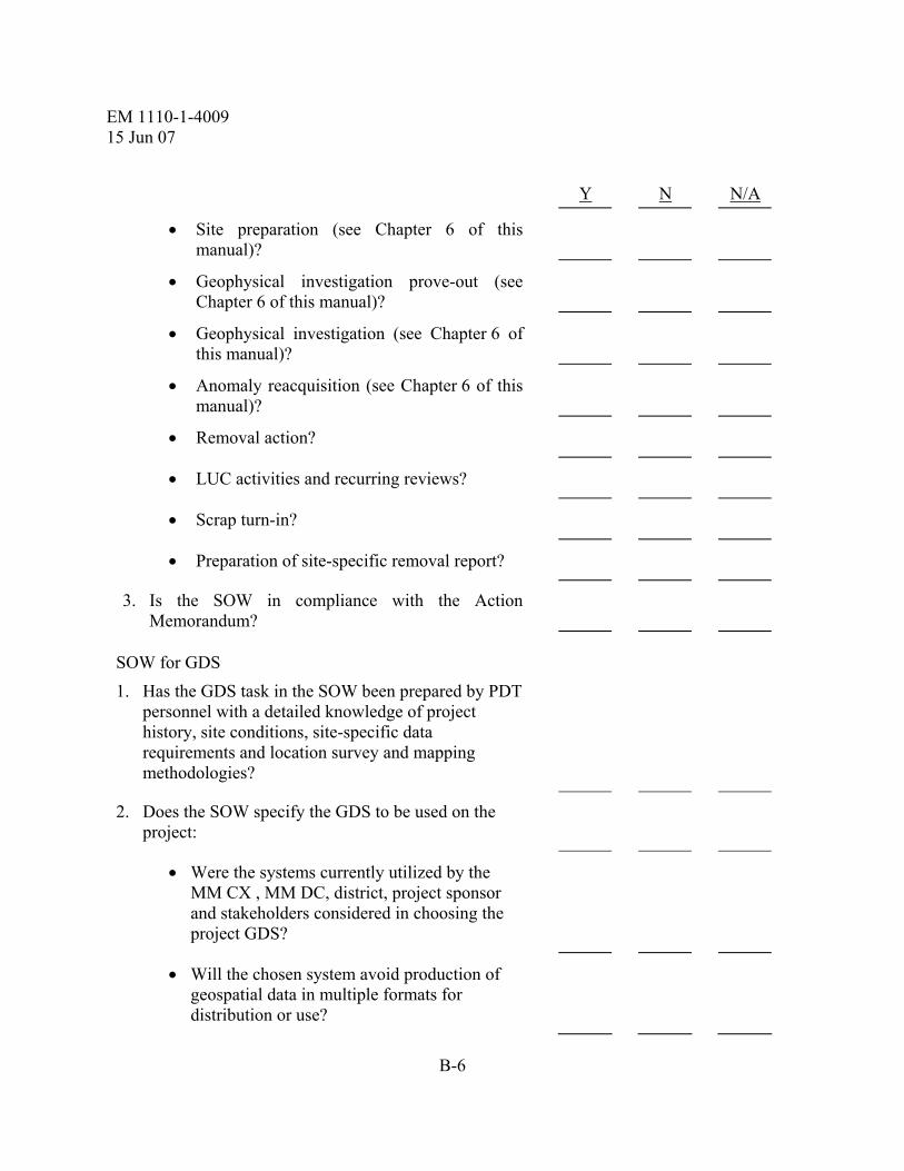
EM 1110-1-4009 15 Jun 07
B-6
Y N N/A
• Site preparation (see Chapter 6 of this manual)?
• Geophysical investigation prove-out (see Chapter 6 of this manual)?
• Geophysical investigation (see Chapter 6 of this manual)?
• Anomaly reacquisition (see Chapter 6 of this manual)?
• Removal action?
• LUC activities and recurring reviews?
• Scrap turn-in?
• Preparation of site-specific removal report?
3. Is the SOW in compliance with the Action Memorandum?
SOW for GDS
1. Has the GDS task in the SOW been prepared by PDT personnel with a detailed knowledge of project history, site conditions, site-specific data requirements and location survey and mapping methodologies?
2. Does the SOW specify the GDS to be used on the project:
• Were the systems currently utilized by the MM CX , MM DC, district, project sponsor and stakeholders considered in choosing the project GDS?
• Will the chosen system avoid production of geospatial data in multiple formats for distribution or use?

EM 1110-1-4009 15 Jun 07
B-7
Y N N/A
• Will the chosen system accomplish the current mission but also allow for future reuse or use of the geospatial data by others without translation?
3. Does the SOW specify the spatial coordinate reference system to be used?
4. Is the chosen spatial coordinate reference system compatible with the existing district or project sponsor GDS activities?
5. Does the SOW state that all GDS activities should be managed by a qualified GIS manager with a minimum of 3 years direct experience managing geospatial data systems within the system environment to be used for the project (e.g., ArcInfo, ArcView, or Microstation MGE)?
6. Does the SOW state that all surveying and mapping activities must be conducted under the responsible charge of a Registered or Professional Land Surveyor registered and/or licensed in the state in which the work will be conducted?
7. Does the SOW state that the Field Surveyor assigned to the project must have a minimum of 5 years experience as a Survey Party Chief?
8. Does the SOW require that a qualified UXO Technician II accompany the Field Surveyor at all times, unless it is decided by the UXO Technician II and the OE Safety Specialist that the UXO Technician II is not required?
9. Does the SOW state that the contractor must follow the safety requirements in EM 385-1-1?
10. Does the SOW specify the requirements for control point establishment?

EM 1110-1-4009 15 Jun 07
B-8
Y N N/A
11. Does the SOW state the specifications for monument caps and monument identification?
12. Does the SOW give procedures for plotting the control points?
13. Does the SOW give requirements for grid corner establishment?
14. Does the SOW state that the Registered Land Surveyor/Professional Land Surveyor should sign drawings that contain boundaries, legal descriptions, or parcel location information?
15. Does the SOW prescribe the units to be used for recording and plotting location survey and mapping activities, as specified by the district or customer? (note: units of measure – 1 US survey foot = 0.3048006096 meters)
16. Does the SOW require that location surveys be connected to existing local, state or national control monuments and reference d to an appropriately recognized installation, local state, or worldwide coordinate system as specified by the PDT?
17. Does the SOW specify the minimum acceptable accuracy standards for positional data for project control markers (i.e., monuments, benchmarks)?
18. Is densification of the existing project control markers required?
19. If densification of existing project control markers is required, is this specified in the SOW?
20. Does the SOW specify that at least two existing markers will be used as a baseline for the project geospatial coordinate reference system?
21. Has the PDT specified acceptable limits of error in

EM 1110-1-4009 15 Jun 07
B-9
Y N N/A terms of accuracy and precision based on the nature and purpose of each location surveying and mapping activity or product?
22. Has the PDT developed site-specific standards for the format, transfer and storage of all location surveying and mapping data? (including digital data collector (raw) files)
23. Does the SOW specify that Tri-Service CADD/GIS Technology Center SDSFIE standard will be used for all deliverables?
24. Does the SOW specify additional site-specific standards developed by the PDT for the format, transfer, and storage of all geospatial data consistent with EM 1110-1-2909?
25. Were the following factors considered by the PDT when developing site-specific standards:
• Compatibility with selected GDS without modification or additional software?
• Format of existing digital data and geospatial referenced mapping?
• Usability by all parties of concern including stakeholders?
26. Does the SOW prescribe the units to be used in recording and plotting geospatial data, as specified by the district or project sponsor? (note: transformation between datums and coordinate systems may be based on different programs (e.g., CORPSCON, Blue Marble, Geosoft) and small differences in the final coordinates may occur because of this.
27. Does the SOW specify the minimum acceptable limits for accuracy and precision based on the nature

EM 1110-1-4009 15 Jun 07
B-10
Y N N/A and purpose of the GDS?
28. Does the SOW require contractor QC of GDS activities and products, including independent tests that may be periodically reviewed by the government?
29. Has the PDT established the level of production control and rigor with which quality assessments must be made consistent with the project-specific GDS requirements?
30. Are the following deliverables specified in the SOW:
• Unique items created and/or used to create the end products and the narrative and description required?
• Digital data in the media as specified in the SOW along with all other supporting files?
• Data manual as an ASCII file documenting all production and work files necessary for an outsider to recreate all products and determine the location, names, structures and associations of the data, such as layer description, file references (as appropriate), etc.?
• Completed monument descriptions (as part of GIS/database or spreadsheet).
• Unique items created and/or used to create the end products and the narrative and description required?
• Required location, project and grid maps?
• The negatives and three sets of prints of the aerial photographs taken for the project, if aerial photography is required in the SOW?

EM 1110-1-4009 15 Jun 07
B-11
Y N N/A
• Two hard copies of each final map and two copies of the digital data delivered to the MM DC?

EM 1110-1-4009 15 Jun 07
B-12
Table B-2. Cost Estimate Preparation Checklist
Project Name: ________________________________________________
Project Location: ________________________________________________
MM DC Representative: ________________________________________________
Preparer’s Name and Title: ________________________________________________
Date of Preparation: ________________________________________________
Y N N/A
Prior to beginning work on cost estimate
1. Is the cost estimate being prepared for internal budgetary purposes (i.e., to obtain program funding)? If yes, a rough order of magnitude estimate may be prepared.
2. Is the cost estimate being prepared for contract procurement (i.e., for use in contract negotiations)? If yes, a detailed cost estimate is required.
3. Has the SOW been developed and approved?
4. Have the phase of the project and the following items that will impact the project’s cost been considered (this list is not all inclusive):
Note: This checklist is only to be used to show whether items have been considered in the estimate, and not as a cost worksheet.
• Size of areas of concern?
• Site risk?
• Type of MEC?
• Soil type?

EM 1110-1-4009 15 Jun 07
B-13
Y N N/A
• Topography?
• Vegetation type?
• MEC density?
• Required removal depth?
• Amount of munitions debris?
• MC Sampling Analyses?
• Special environmental and safety concerns (e.g., presence of CWM, requirements for engineering controls, sampling and analysis requirements such as air monitoring, etc.)?
• Production rates?
• In-house or contracted?
• Percent of property to be investigated?
• Surveying methods?
• Data format requirements (i.e., digital or non-digital)?
• PPE level required?
• Type of operation to be performed (e.g., search only or search and recovery)?
• Number and type of UXO technicians required?
• Equipment and vehicles required (e.g., magnetometer, towed array, earth moving machinery, recovery vehicles)?

EM 1110-1-4009 15 Jun 07
B-14
Y N N/A
• Expected time duration?
• Access restrictions?
• Political considerations?
• Start date?

EM 1110-1-4009 15 Jun 07
B-15
Table B-3. Site Visit Review Checklist Project Name: ______________________________________________________________ Project Location:____________________________________________________________ MM DC Representative:______________________________________________________ Reviewer’s Name and Title: ___________________________________________________ Date of Review: ____________________________________________________________
Y N N/A
General.
1. Will the initial site visit be a:
• Government site visit?
• Contractor site visit?
• Combined government and contractor site visit?
Government Site Visit Attendees.
1. Are the following personnel attending the government site visit:
• PM (optional)?
• MM DC Representative(s) (optional)?
• OE Safety Specialist?
• Project Engineers (optional)?
• Cost estimator (optional)?
• Project Geophysicist (optional)?

EM 1110-1-4009 15 Jun 07
B-16
Y N N/A
* Government geophysicist may bring along geophysical equipment to assess the capabilities of different instrumentation at the site.
• Project Chemist (optional - applies primarily to sites with significant MC concerns)?
Contractor Site Visit Attendees.
1. Are the following personnel, at a minimum, attending the contractor site visit:
• Contractor PM?
• Contractor UXO Technician III?
• Project Geophysicist (optional)?
• PM (government) (optional*)?
• MM DC Representative (optional*)?
• OE Safety Specialist (optional*)?
• Project Chemist (optional - applies primarily to sites with significant MC concerns)?
* One PDT representative, at a minimum, is required to accompany the contractor during the site visit.
2. Has the PM determined that the contractor is limited to a certain number of personnel to attend the site visit? (If yes, state maximum number allowable.)
3. Has the PM confirmed that the contractor personnel are qualified IAW USACE Personnel/Work Standards?
Site Visit Requirements. Prior to the site visit, the PDT should ensure that the following requirements are

EM 1110-1-4009 15 Jun 07
B-17
Y N N/A
fulfilled:
• Have site-specific reports been reviewed?
• Have any data gaps in the existing site data been identified?
• Has the PM obtained rights of entry, if applicable?
ASSHP. Has the PDT ensured that an ASSHP has been prepared and approved prior to the site visit?

EM 1110-1-4009 15 Jun 07
B-18
Table B-4. Work Plan Review Checklist Project Name: ________________________________________________________________
Project Location:______________________________________________________________
MM DC Representative:________________________________________________________
Reviewer’s Name and Title: _____________________________________________________
Date of Review: ______________________________________________________________
Y N N/A
General
1. Have the following PDT members, at a minimum, reviewed the Work Plan:
• PM?
• MM DCDC?
• Project engineers in relevant subject matter areas?
• OE Safety Specialist?
• Industrial Hygienist?
• Cost Engineer?
• Project Geophysicist?
• Project Chemist?
2. Is the Work Plan in compliance with the project SOW?
3. Is the Work Plan in compliance with contract requirements?
Work Plan Checklist
1. The PDT will ensure that the Work Plan has been prepared IAW the SOW and contract specifications. The Work Plan will generally include the following chapters:
• Project purpose and scope?
• Work plan organization?

EM 1110-1-4009 15 Jun 07
B-19
Y N N/A
• Project location?
• Site description, including site location, topography, climate, vegetation, and site geology?
• Site history?
• Current and projected land use?
• Summary of previous site investigations?
• Fill Information for anticipated MEC?
• Initial summary of MEC risk at the site?
• Risk Assessment Subplan (for MC risk assessments conducted with RI/FSs)?
2. Technical Management Plan. Are the following topics discussed in this chapter:
• Project objectives?
• Project organization?
• Project personnel?
• Project communication and reporting?
• Deliverables?
• Schedule?
• Periodic Reporting?
• Costing and billing?
• Public relations support?
• Subcontractor management procedures?
• Field operation management procedures?
• Data Management Procedures?
• DQOs?
3. Field Investigation Plan. Are the following topics discussed in this chapter:
• Overall Approach?

EM 1110-1-4009 15 Jun 07
B-20
Y N N/A
• Identification of Areas of Concern?
• Location Surveys and Mapping Plan?
• Geographic Information Systems (GIS) Plan?
• Geophysical Prove-out Plan and Report?
• Geophysical Investigation Plan?
• Intrusive Investigation. Does this subchapter discuss the planning and implementation of the following:
− General methodology?
− MEC accountability and record management?
− UXO personnel and qualifications?
− MEC sampling locations?
− MEC sampling procedures?
− Munition with the Greatest Fragmentation Distance (MGFD)?
− Minimum separation distances (MSDs)?
− MEC identification?
− MEC removal?
− MEC storage?
− MEC disposal procedures?
− MEC disposal alternatives?
• Investigation Derived Waste Plan?
• Risk Characterization and Analysis?
• Analysis of Land Use Controls?
• Preparation of Recurring Review Plan?

EM 1110-1-4009 15 Jun 07
B-21
Y N N/A
4. Quality Control Plan.
• Does this chapter adequately discuss quality control procedures for the munitions response project?
5. Explosives Management Plan.
• Does this chapter describe how demolition explosives will be managed, planned and implemented during MEC operations?
6. Explosives Siting Plan.
• Does this chapter adequately describe the safety criteria for siting explosives operations at the site?
7. Environmental Protection Plan.
• Is a list of potential applicable or relevant and appropriate requirements (ARARs) provided?
• Is an initial determination provided as to the actual applicability of these ARARs to the project?
• Is the procedure by which ARARs will be identified and complied with during field investigation activities described?
• Does the EPP note that evaluation of ARARs is an iterative process to be performed throughout the life of the project?
• Does the EPP detail the identification and location of, as well as provide procedures and methods to protect and/or mitigate resources/sites of all known:
− Endangered/threatened species within the project site?
− Wetlands within the project site?
− Cultural, archaeological, and water resources within the project site?
− Coastal zones within the project site?

EM 1110-1-4009 15 Jun 07
B-22
Y N N/A
− Trees and shrubs that will be removed within the project site?
− Existing waste disposal sites within the project site?
• Does the EPP include a description of the joint environmental survey conducted prior to the start of any on-site work by the contractor and CO/COR or other government personnel?
• Does the EPP detail mitigation procedures for the following:
− All manifesting, transportation, and disposal of wastes?
− All burning activities?
− Dust and emission control?
− Spill control and prevention?
− All storage areas and temporary facilities?
− Access routes?
− Trees and shrubs protection and restoration?
− Control of water run-on and run-off?
− Decontamination and disposal of equipment?
− Minimization of areas of disturbance?
• Does the EPP describe procedures for post-activity clean up to be accomplished?
8. Property Management Plan.
• Does this chapter detail procedures for the management of government property in accordance with FAR Part 45.5 and its supplements?
9. Interim Holding Facility Siting Plan.
• Does this chapter describe siting and security measures for the IHF?

EM 1110-1-4009 15 Jun 07
B-23
Y N N/A
10. Physical Security Plan.
• Does this chapter describe the areas of security interest related to the site?
• Does this chapter specify the equipment, forces, and devices used to protect RCWM?
11. References.
• Does the Work Plan include appropriate references?
12. Appendices. Are the following documents included as appendices to the Work Plan:
• SOW?
• Site maps?
• Points of contact?
• Site Safety and Health Plan?
• Environmental Sampling and Analysis Plan? (Refer to Table B-7 and EM 200-1-3)
• Forms?
• MSD calculation sheets?
• Resumes for key personnel and personnel filling core labor categories, EOD school graduation certificates if applicable?
• Technical Project Planning Work Sheets?

EM 1110-1-4009 15 Jun 07
B-24
Table B-5. Geospatial Data Systems Project Name: ______________________________________________________________
Project Location:____________________________________________________________
MM DC Representative:______________________________________________________
Preparer’s Name and Title: ____________________________________________________
Date of Preparation: _________________________________________________________
Y N N/A
1. Locating of Existing Geospatial Data:
• Types?
• Accuracy?
2. Newly Collected Geospatial Data:
• Types?
• Accuracy?
• Location?
3. Proposed System Methods and Procedures:
• Hardware and Software?
• Personnel?
• Work Instructions/Data Format?
• Data Processing?
• Analysis Support?
• Communication/Data Transfer?
• Data Storage?

EM 1110-1-4009 15 Jun 07
B-25
Y N N/A
4. Quality Control:
• Data Validation?
• Quality control should be provided by the surveying contractor if used.
• If the contractor is conducting the surveying themselves, documented quality control metrics should be used. Examples of possible metrics include: - Specifying closure metrics on the survey - Specifying backsight tolerances on angular closure (i.e., 15 sec for distance less than 100-feet, 10 sec. for longer distances)
5. Interim Deliverables?
6. Final Deliverables?
Planning Considerations
1. Spatial Reference System:
2. Existing Control Markers:
• Density?
• Accuracy?
• Accessibility?
3. Project and Grid Controls (New):
• Requirements?
• Material?
• Location?
• Construction?

EM 1110-1-4009 15 Jun 07
B-26
Y N N/A
• Identification?
• Accuracy?
4. Proposed Methods and Procedures:
• Equipment?
• Personnel?
• Safety?
• Work Instruction?
• Data Processing?
• Production Rates?
5. QC:
• Instrument Calibration?
• Data Validation?
6. Interim Reporting?
Electronic Submittal
1. Are disks readable?
2. Are the disks labeled and dated?
3. Are the files in the correct format, as requested in SOW? (e.g., DOS, Win 95/98/NT, UNIX, etc.)
4. Do they follow the SDSFIE, if required?
5. Are all of the detailed files included on the disks to make a complete data set?
6. Is each individual file readable and useable?

EM 1110-1-4009 15 Jun 07
B-27
Y N N/A
7. Is the file located electronically (geospatially) at the correct location on the ground?
8. Is the coordinate system correct?
9. Are all files geographically located in the correct plane and datum?
10. Are the X, Y, and Z coordinates correct within the file?
11. Have the correct number of copies been submitted, depending on the submittal stage?
Paper or Hard Copy Submittal
1. Is the sheet the requested size?
2. Does it contain a standard border?
3. Is the correct grid system and associated control shown on the sheet?
4. Has the title block been completed (i.e., all required blocks filled in)?
5. Is the sheet plotted at the scale shown in the title block?
6. Are there grid marks or tics (meters, feet, both, Lat/Lon, Local, etc.)?
7. Is there a North arrow (magnetic declination, true North, and grid North) and graphical scale shown on the sheet, both graphically and printed text?
8. Is there a legend for associated symbols on the sheet? Or, are all symbols used in a project shown on one legends and notes page?
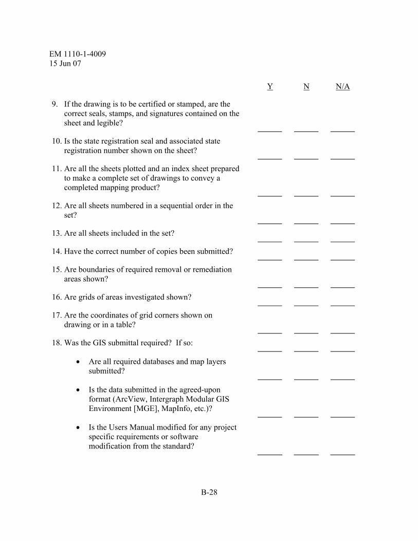
EM 1110-1-4009 15 Jun 07
B-28
Y N N/A
9. If the drawing is to be certified or stamped, are the correct seals, stamps, and signatures contained on the sheet and legible?
10. Is the state registration seal and associated state registration number shown on the sheet?
11. Are all the sheets plotted and an index sheet prepared to make a complete set of drawings to convey a completed mapping product?
12. Are all sheets numbered in a sequential order in the set?
13. Are all sheets included in the set?
14. Have the correct number of copies been submitted?
15. Are boundaries of required removal or remediation areas shown?
16. Are grids of areas investigated shown?
17. Are the coordinates of grid corners shown on drawing or in a table?
18. Was the GIS submittal required? If so:
• Are all required databases and map layers submitted?
• Is the data submitted in the agreed-upon format (ArcView, Intergraph Modular GIS Environment [MGE], MapInfo, etc.)?
• Is the Users Manual modified for any project specific requirements or software modification from the standard?

EM 1110-1-4009 15 Jun 07
B-29
Table B-6. Geophysical Investigations Checklist
Project Name: Project Location:
MM DC Representative: Preparer’s Name and Title: Date of Preparation:
Y N N/A
Geophysical Planning Considerations:
1. Is the geophysical planning being performed by or under the supervision of a “qualified” geophysicist?
2. Have objectives been considered for the geophysical investigation in the following areas:
• Analog Geophysical surveying (Mag and Dig)?
• Digital Geophysical mapping?
• Geophysical interrogation?
3. Has the geophysical investigation planning process been addressed:
• Experienced personnel?
• Geophysical systems?
• Analysis procedures?
• Navigational accuracy and precision?
Geophysical Instrument Considerations:
1. Were the following factors which affect geophysical systems been considered:

EM 1110-1-4009 15 Jun 07
B-30
Y N N/A
• Military munition composition?
• Military munition size?
• MEC depth?
• Military munition fuzing?
• Background interference from metallic scrap?
• Soil composition and geology?
• Vegetation and terrain?
• Cultural features?
Selection of Geophysical Systems
1. Which type of geophysical instrument is most appropriate:
• Active (TDEM or FDEM)?
• Passive (magnetometer or gradiometer)?
MEC Detection Capabilities
1. Have the following factors been considered in determining the detection capabilities in the field for a geophysical instrument?
• Vegetation?
• Terrain?
• Geologic noise/gradients?
• Cultural noise?
• Munitions debris?

EM 1110-1-4009 15 Jun 07
B-31
Y N N/A
• MEC penetration beyond detection?
• QA items detected?
MEC Detection Depths
1. Have maximum MEC detection depths been estimated in accordance with Table 6.1?
2. Has the maximum possible depth of MEC at the site been estimated?
Geophysical Systems and Electric Fuze Safety
Have the following safety precautions been applied to the project?
1. Passive Systems:
• Are the passive systems being used in accordance with the manufacturer’s instructions?
2. Active Systems:
• Prior to using an active instrument, has the operator determined if any fuzing systems exist at the sites that contain any electrical components?
• If a MEC site does not contain electrical fuzes, are the active systems being used IAW the manufacturer’s instruction?
• Has the latest version of the Active EMI Effect on Electronic Fuzes been reviewed to determine the expected effect of the instrumentation on fuzes suspected to be on-site?

EM 1110-1-4009 15 Jun 07
B-32
Y N N/A
• If a MEC site does contain or is reasonably expected to contain electrical fuzes, has the instrument operator submitted a request for a waiver from the Design Center Safety Manager?
Analysis Software
1. Has the appropriate analysis software been selected for the specific instrument?
2. Prior to using the software, have navigation adjustments been made?
3. Are the data in the correct, project-specific coordinate system?
4. Are the geophysical data in the units specified by the software’s instruction manual?
Navigation System
1. Which type of coordinate system was selected:
• Temporary (local coordinate system)?
• Permanent (UTM or State Plane)?
2. What type of positional system was used?
Line and Fiducial
DGPS
Laser Based RTS
Ultrasonic
RF
Other

EM 1110-1-4009 15 Jun 07
B-33
Y N N/A
3. Are there sufficient horizontal and vertical control points and/or bench marks at the project site?
Are the accuracies of the control point/bench mark coordinates sufficient for the needs of the selected positioning system?
Are the coordinates of the control points/bench marks available in the project-specific coordinate system?
Have the limitations (or assumptions) of the selected positioning system(s) been considered and evaluated against their intended use?
GPO Planning
1. Have DQOs been developed?
2. Has a Work Plan been developed for the prove-out?
3. Does the GPO Work Plan describe the following:
• GPO grid location and construction?
• Factors influencing prove-out grid location and construction:
− Terrain, vegetation, geological conditions?
− Proximity to the field site?
− Isolation from overhead power lines, radio transmitters, underground utilities, etc?
The establishment of project specific QC measures and metrics for selected detection and navigation instruments as well as processing and interpretation methods?

EM 1110-1-4009 15 Jun 07
B-34
Y N N/A
− Convenient access?
− Likelihood that the area will be disturbed during use?
− Rights-of-Entry?
− Possibility of pre-existing buried MEC?
• Pre-Seeding geophysical mapping?
• Have the following items been considered regarding pre-seeding:
− Size and configuration?
− Survey accuracy?
− Layout?
− Seeded items?
− Depths and orientations?
− Cultural interference?
− Munitions debris interference?
• Data collection variables, including:
− Instrument height?
− Instrument orientation?
− Direction of travel?
− Measurement interval?
− Lane width?
• Data analysis and interpretation?

EM 1110-1-4009 15 Jun 07
B-35
Y N N/A
• Data evaluation?
• Selection of detection systems?
• Establish project specific QC measures and/or metrics for the selected detection instruments?
Geophysical Investigation Plan
1. Does the Geophysical Investigation Work Plan address the following:
• Site Description:
− Geophysical DQO measures and metrics as well as their frequencies and reporting requirements?
− Specific Area(s) to be investigated, including a Survey Mission Plan Map?
− Past, current and future use?
− Anticipated MEC type, composition and quantity?
− Depth anticipated?
− Digital Topographic Maps?
− Vegetation?
− Geologic conditions (including bedrock type, mineralization and depth)?
− Soil conditions (including soil type/composition, typical moisture content, and thickness)?

EM 1110-1-4009 15 Jun 07
B-36
Y N N/A
− Surface water conditions (does area to be surveyed include ponds, lakes, streams or shallow water coastlines?)
− Man-made features potentially affecting geophysical investigations?
− Site-specific dynamic events such as tides, unusually strong winds, or other unusual factors affecting site operations?
− Overall Site Accessibility and Impediments?
− Potential Worker Hazards?
• Geophysical Investigation Methods:
− Survey Type?
− Equipment?
− Procedures?
− Personnel?
− Production Rates?
− Data Spatial Density?
• Instrument Standardization:
− Instrument drift?
− Standardization procedures?
− Abbreviated standardization checks?
− Instrument response to a known standard?
• Data Processing, Correction and Analysis:

EM 1110-1-4009 15 Jun 07
B-37
Y N N/A
− Instrument drift correction?
− Diurnal drift correction?
− Digital filtering and enhancement?
− Anomaly selection process?
− Correlation with ground truth?
• Dig Sheet Development?
• Anomaly Reacquisition?
• Feedback Process?
• Quality Control?
• Corrective Measures?
• Records Management?
• Interim Reporting?
• Map Format?
Sectorization
1. When defining sectors, were the following factors considered?
• Former military use?
• Anticipated MEC type?
• Anticipated MEC distribution?
• Terrain and vegetation?
• Current land use?

EM 1110-1-4009 15 Jun 07
B-38
Y N N/A
• Natural and cultural boundaries?
Surveying within a Sector
1. Which surveying methodology is appropriate for the sector:
• 100 percent surveying?
• Biased surveying?(Increased data density in areas of interest)
• Probability surveying?
• If probability surveying is selected, which type of strategy will be used in the sector:
− Random pattern grid surveying?
− Hybrid surveying?
− Transect surveying?
− Meandering path surveying?
Geophysical Data Acquisition
1. Are SOPs provided for all processes and procedures associated with the geophysical data acquisition program?
Excavating Anomalies within a Grid
1. Which methodology for selecting anomalies for excavation is appropriate for the grid?
• 100 percent anomaly excavation?
• Statistical anomaly excavation?
• 100% having predefined anomaly characteristics with statistical sampling of all others.

EM 1110-1-4009 15 Jun 07
B-39
Y N N/A
Data Interpretation
1. Was the geophysical data interpreted after the geophysical investigation?
2. Were the project objectives met?
Geophysical Anomaly Dig Sheets
1. Are standard operating procedures (SOPs) provided for all processes and procedures associated with the geophysical mapping program?
2. Are the frequencies and reporting needs of the quality control measures included in the geophysical mapping plan?
3. Do the dig sheets contain the following information:
• Project site?
• Grid number?
• Anomaly number?
• Name of the geophysical contractor?
• Name of the responsible field geophysicist?
• Date geophysical mapping occurred?
• Name of the responsible analyst?
• Date the data was geophysically analyzed?
• Predicted location coordinates?
• Predicted depth to top of item (optional)?
• Comments.

EM 1110-1-4009 15 Jun 07
B-40
Y N N/A
Anomaly Reacquisition and Marking
1. Was the same type of instrument used for reacquisition as that used in the geophysical survey? (Does the instrument used in reacquisition measure the same property (magnetic field or conductivity) as the original instrument? No contacts should still be investigated using the original instrument. If a similar, but not the same instrument is used in reacquisition, a method for checking anomaly amplitudes between the two similar instruments must be developed and documented.
2. Were discrepancies between the re-acquired locations of anomalies as shown on the dig-sheet and final excavated location recorded and included in the geophysical report?
3. Were discrepancies between the anomaly amplitudes recorded on the digsheet and the anomaly amplitudes recorded during the reacquisition resolved and recorded on the digsheet?
Anomaly Excavation
1. Was the following post-excavation information collected?
• Project site?
• Grid number?
• Anomaly number?
• Excavation contractor?
• Name of the responsible OE Safety Specialist?
• Date of excavation?
• Final excavated location coordinates?
• Weather conditions?

EM 1110-1-4009 15 Jun 07
B-41
Y N N/A
• Anomaly identification?
• Actual depth to top of item?
• Soil type?
• Actual length (optional)?
• Actual diameter (optional)?
• Actual azimuth (optional)?
• Item material composition (optional)?
• Comments.
Digital Data Format and Storage
1. Were the requirements and standards for a digital data management system tailored for the specific ordnance investigative needs of the project?
2. Has the geophysical data been stored in a format and media that permits loading, storage and use of GIS workstations without modification or additional software?
Quality Management
1. Were all of the quality control measures and metrics met?
• If not all measures and metrics were met, for those that failed, were root-cause analyses performed and corrective actions taken?
2. Were procedures for product quality management followed for:
• Delivering a completed, cleared Grid?
• Producing a completed investigation report?

EM 1110-1-4009 15 Jun 07
B-42
Y N N/A
• Producing a completed GPO report with the specified as-built details?
• Delivering completed dig sheets?
• Delivering properly formatted and documented raw and final geophysical data?
• Including complete and legible maps of the data and interpretations
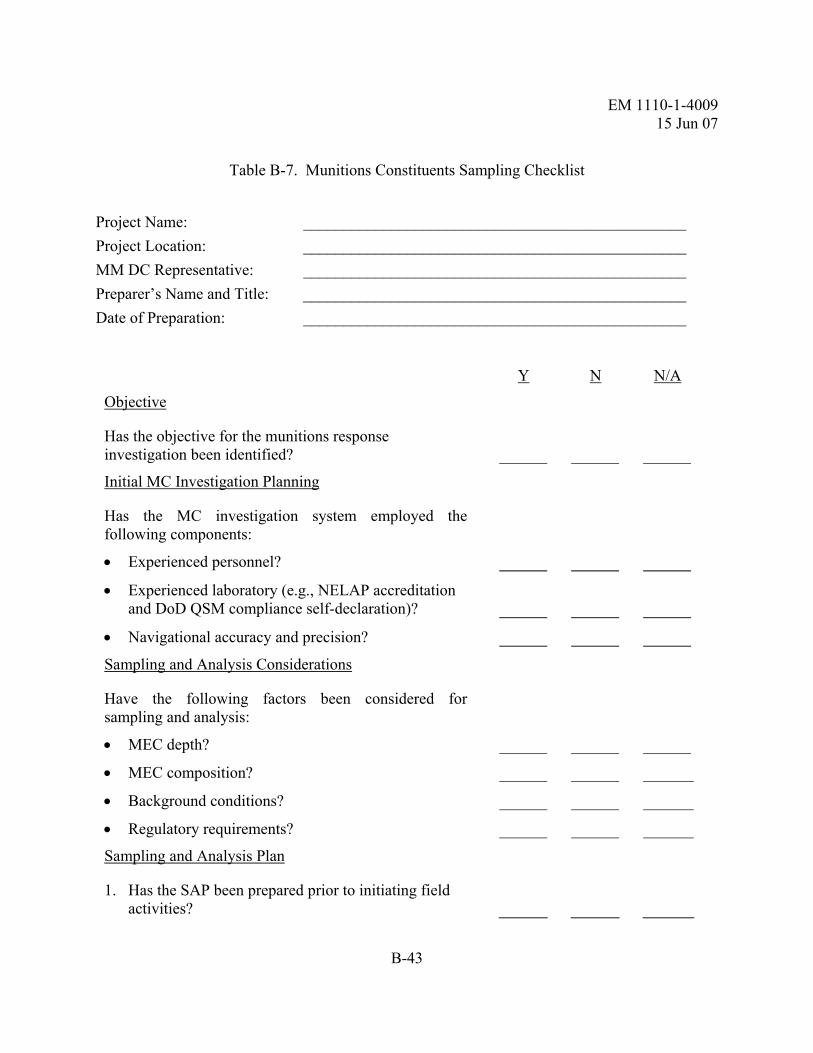
EM 1110-1-4009 15 Jun 07
B-43
Table B-7. Munitions Constituents Sampling Checklist
Project Name: ________________________________________________ Project Location: ________________________________________________ MM DC Representative: ________________________________________________ Preparer’s Name and Title: ________________________________________________ Date of Preparation: ________________________________________________
Y N N/A
Objective
Has the objective for the munitions response investigation been identified?
Initial MC Investigation Planning
Has the MC investigation system employed the following components:
• Experienced personnel?
• Experienced laboratory (e.g., NELAP accreditation and DoD QSM compliance self-declaration)?
• Navigational accuracy and precision?
Sampling and Analysis Considerations
Have the following factors been considered for sampling and analysis:
• MEC depth?
• MEC composition?
• Background conditions?
• Regulatory requirements?
Sampling and Analysis Plan
1. Has the SAP been prepared prior to initiating field activities?

EM 1110-1-4009 15 Jun 07
B-44
Y N N/A
2. Has the SAP been prepared IAW ER 1110-1-263, and EM 200-1-3?
3. Are the Laboratory QA/QC plan and applicable Standard Operating Procedures included in the SAP?
4. Has the SAP submitted to PM and MM DC been approved?
Data Interpretation, Validation, Reporting, and Decision Making
Have the requirements outlined in Section 7-8 been met?
Quality Management
1. Has the QC of the various analytical tasks been provided?
2. Have the handling and custody requirements for all QC samples been administered?
Electronic Data Deliverables
1. Has EDD been specified in SOW?
2. Is implementation included in the Work Plan?
3. If ADR (or similar EDD) specified, does Work Plan address automated portions of data review?

EM 1110-1-4009 15 Jun 07
B-45
Table B-8. Blast and Fragmentation Protection Review Checklist
Project Name: ______________________________________________________________ Project Location:____________________________________________________________ MM DC Representative:______________________________________________________ Reviewer’s Name and Title: ___________________________________________________ Date of Review: ____________________________________________________________
Y N N/A
Engineering Considerations for SOW Preparation
1. Has the SOW properly taken into account the physical characteristics of the site?
2. Has the SOW taken into account the type of munitions response being contemplated?
3. Has the SOW taken into account the characteristics of the probable MEC items that will be encountered at the site?
4. Has the correct MGFD been identified for the site?
Minimum Separation Distances
1. Are there MSDs being proposed for the site?
2. Have the following criteria for an unintentional detonation been evaluated:
• MSD for unintentional detonations: Which will provide the greatest distance?
− Overpressure at a K value of 50?
− Maximum fragmentation distance?
− 200 feet?
• Team Separation Distance: Which will provide the greatest distance?
− Overpressure at a K value of 50?
− 1/600 distance?

EM 1110-1-4009 15 Jun 07
B-46
Y N N/A
• If the 1/600 distance is being used:
− Has justification been provided?
− Has approval been given by the MM CXCX?
3. Have the following criteria for an intentional detonation been evaluated:
• MSD: Which will provide the greatest distance?
− Maximum fragmentation distance?
− Overpressure at a K value of 328?
− 200 feet?
Explosives Siting Plan Review Considerations
1. Has a map been included with the Explosives Siting Plan and is it at an appropriate scale?
2. Does the map identify the MRSs, the location for the explosives storage magazine, and any planned or established demolition areas?
3. Has the MRS been properly identified and has an appropriate MSD been calculated for the area?
4. Have the Q-D arcs for the MRS been drawn from the outermost edge of each area?
5. Has the proposed explosives storage magazine been properly sited?
6. Has the proposed demolition area been properly sited?
7. Have footprint areas for any Blow-in-Place areas, Collection Points, or In-Grid Consolidated Shots been discussed in the Explosives Safety Plan?
8. Has an appropriate team separation distance been identified between intrusive investigation teams in the Explosives Safety Plan?
9. Have any engineering controls been proposed in the Explosives Safety Plan?
10. Does the CDC have a DDESB-approved siting plan for the site, if a CDC is to be used?

EM 1110-1-4009 15 Jun 07
B-47
Y N N/A
Engineering Controls for Unintentional/Accidental Detonations
Barricades. The PDT will consider the following elements regarding barricade selection:
• Have barricades been specified for the project?
• Has the correct barricade been specified for the application IAW the DOD standards?
• If the proposed barricade has not been previously approved, has a complete structural design package been submitted to the MM CXCX?
• Has the design package been forwarded through appropriate channels to DDESB for review?
Engineering Controls for Intentional Detonations
1. Is soil being proposed as an engineering control for an intentional detonation?
2. Has the amount of soil to be placed on top of the MEC been properly calculated?
3. Are sandbags being proposed as an engineering control to limit the fragmentation and overpressure from an intentional MEC detonation?
4. Has the amount of sandbags being proposed been properly calculated based on the type of MEC to be destroyed?
5. Is a water barrier being proposed as an engineering control for an intentional detonation?
6. Have the requirements for water barricades detailed in HNC-ED-CS-S-00-3 been followed?
7. Has a CDC been specified for use on the site?
8. Is the CDC capable of safely containing the blast and fragmentation effects of the MEC to be found at the site?

EM 1110-1-4009 15 Jun 07
B-48
Table B-9. Munitions Constituents Sampling Checklist
Project Name:
Project Location:
MM DC Representative:
Preparer’s Name and Title:
Date of Preparation:
Y N N/A Objective Has the objective for the munitions response investigation been identified?
Initial MC Investigation Planning Has the MC investigation system employed the following components:
• Experienced personnel? • Experienced laboratory? • Navigational accuracy and precision? Sampling and Analysis Considerations
Have the following factors been considered for sampling and analysis:
• MEC depth? • MEC composition? • Background conditions? • Regulatory requirements? Y N N/A Sampling and Analysis Plan 1. Has the SAP been prepared prior to initiating field
activities?
2. Has the SAP been prepared IAW ER 1110-1-263, ER 200-3-1, and EM 200-1-3?
3. Are the Laboratory QA/QC plan and applicable Standard Operating Procedures included in the SAP?
4. Has the SAP submitted to PM and MM DC been approved?

EM 1110-1-4009 15 Jun 07
B-49
Data Interpretation, Validation, Reporting, and Decision Making
Have the requirements outlined in Section 7.8 been met? Quality Management 1. Has the QC of the various analytical tasks been
provided?
2. Have the handling and custody requirements for all QC samples been administered?
Electronic Data Deliverables 1. Has EDD been specified in SOW/PWS? 2. Is implementation included in the Work Plan? 3. If SEDD (or similar EDD) specified, does Work Plan
address automated portions of data review?

EM 1110-1-4009 15 Jun 07
B-50
This page intentionally left blank

EM 1110-1-4009 15 Jun 07
C-1
APPENDIX C QASP TEMPLATE
C-1. General. The following is a QASP template that shall be modified for specific project needs.
QUALITY ASSURANCE SURVEILLANCE PLAN
[City, State] 1. INTRODUCTION
This Performance-Based Quality Assurance Surveillance Plan (QASP) has been developed pursuant to the requirements of the Performance-Based Statement of Work in Contract No. [Insert specific project contract No.]. This plan sets forth procedures and guidelines that the U.S. Army Corps of Engineers (USACE) will use in evaluating the technical and safety performance of the Contractor. A copy of this plan will be furnished to the Contractor so that the Contractor will be aware of the methods that the Government will employ in evaluating performance on this contract and address any concerns that the Contractor may have prior to initiating work.
2. PURPOSE OF THE QASP
• Confirm that the action is conducted utilizing proper procedures and in
accordance with the approved work and safety plans; • Define the roles and responsibilities of participating Government officials; • Define the types of work to be performed with required end results; • Document the evaluation methods that will be employed by the Government in
assessing the Contractor’s performance; • Provide the Surveillance Activities Table and Corrective Action Request (CAR)
form that will be used by the Government in documenting and evaluating the Contractor’s performance; and
• Describe the process of performance documentation.
3. ROLES AND RESPONSIBILITIES OF PARTICIPATING GOVERNMENT
OFFICIALS
The USACE Design Center Project Manager (MM DC POC): [Shall be modified for project needs]
• Provides overall guidance to the contractor when necessary or requested for purposes of PWS/SOW clarification.

EM 1110-1-4009 15 Jun 07
C-2
• Reviews vouchers and makes recommendations to the Contracting Officer for payment action based on completion of designated milestones.
• Reports problems or discrepancies to the Contracting Officer as soon as possible. • Oversees the implementation of the QASP. • Reviews contractor submittals. • Initiates periodic contractor evaluations in the Past Performance Information
Management System (PPIMS). • Provide periodic site inspection to review and witness the conduct of MEC
procedures for compliance with the PWS/SOW and for the review of the economy and efficiency of project execution as required by FAR Subpart 16.6 and the PMBP Manual.
• Responsible for the execution of the work on schedule, within budget, in a safe manner, and at a level of quality consistent with the customer’s requirements.
• Periodically reviews contractor performance relative to the contract schedule and budget.
The USACE Contract Specialist: [Shall be modified for project needs] • Monitors contract performance. • Maintains central repository for all QA documents required for payment. • Issues all acceptance/rejection statements.
The Project Engineer or Technical Manager: [Shall be modified for project needs] • Reviews contractor’s Technical Management Plan. • Ensures that all necessary subject matter experts are involved in technical
decisions. • Conducts reviews of contractor submittals for compliance with contract
requirements. • Conducts or supports other surveillance activities as required by the project team. • Supports all on-site QA activities. • Develops the “after action” or “final” Quality Assurance Report. • Provides periodic site inspection to review and witness the conduct of MEC
procedures for compliance with the PWS/SOW and for the review of the economy and efficiency of project execution as required by FAR Subpart 16.6 and the PMBP Manual.
The USACE Safety Specialist: [Shall be modified for project needs] • Conducts reviews of contractor submittals for compliance with DOD, DA and
USACE explosives safety requirements. • Performs Periodic Inspections of contractor compliance with DOD, DA, and
USACE explosives safety requirements and explosives related procedures described in the work plan.
• Conducts or supports other surveillance activities as required by the project team.

EM 1110-1-4009 15 Jun 07
C-3
• Supports all on-site QA activities.
The USACE Geophysicist: [Shall be modified for project needs] • Reviews contractor's Geophysical Investigation Plan, GPO Plan and Report. • Performs, or coordinates with USACE team members to perform periodic
inspections of contractor's compliance with the Geophysical Investigation Plan. • Reviews Quality Control Plan (QCP) reporting requirements and accepts reported
QC measures/standards. • Performs tasks as specified to support the project’s quality goals (placing and
evaluating anomaly selections over blind seed items, randomly selects anomalies for reacquisition and/or excavation, etc.)
• Provides periodic site inspection to review and witness the conduct of MEC procedures for compliance with the PWS/SOW and for the review of the economy and efficiency of project execution as required by FAR Subpart 16.6 and the PMBP Manual.
The USACE Chemist: [Shall be modified for project needs] • Evaluates acceptability of contract laboratory through review of their self
declaration of DoD QSM compliance along with their method-specific SOPs • Reviews the work plan for compliance with standard protocols for Environmental
Sampling and Chemical Analysis. • Conducts reviews of Environmental Sampling and Chemical Analysis Data. • Conducts Periodic Inspections of contractor compliance with environmental
sampling requirements of the work plan to ensure that contractors are utilizing appropriate sampling techniques, collecting the quantity of primary and QA/QC samples as stated in the work plan, and completing the COC correctly with the approved analytical methodology.
• Reviews contractor Investigative Derived Waste (IDW) Plan. • Conducts, or coordinates with USACE Team members to conduct, Periodic
Inspections of contractor compliance with the IDW Plan. • Reviews QCP reporting requirements and accepts reported QC
measures/standards. • Review Daily Quality Control Reports for Environmental Sampling.
The USACE Industrial Hygienist: [Shall be modified for project needs] • Reviews contractor submittals for compliance with DOD, DA, USACE, and
OSHA safety and health requirements. • Performs unscheduled inspections of on-site activities for compliance with safety
and health requirements. • Coordinates medical support training and medical support (as required).
The USACE GIS team member: [Shall be modified for project needs]

EM 1110-1-4009 15 Jun 07
C-4
• Reviews contractor's Geospatial Information and Electronic submittals. • Reviews QCP reporting requirements and accepts reported QC
measures/standards. • Reviews the work plan for compliance with standards and protocol for Geospatial
Information and Electronic requirements. The USACE Chemist: [Should be modified for project needs]
• Participates in preparation of SOW/PWS to ensure that MC requirements are adequately addressed.
• Evaluates acceptability of contract laboratory through review of their self declaration of DoD QSM compliance along with their method-specific SOPs.
• Participates in proposal review to evaluate MC-related tasks. • Participates in TPP meetings, as appropriate. • Reviews the work plan for compliance with standard protocols for Environmental
Sampling and Chemical Analysis. • Conducts reviews of Environmental Sampling and Chemical Analysis Data. • Conducts Periodic Inspections of contractor compliance with environmental
sampling requirements of the work plan to ensure that contractors are utilizing appropriate sampling techniques, collecting the quantity of primary and QA/QC samples as stated in the work plan, and completing the COC correctly with the approved analytical methodology.
• Reviews contractor Investigative Derived Waste (IDW) Plan. • Conducts, or coordinates with USACE Team members to conduct, Periodic
Inspections of contractor compliance with the IDW Plan. • Reviews QCP reporting requirements and accepts reported QC
measures/standards. • Review Daily Quality Control Reports for Environmental Sampling. • Coordinates with PDT and Contractor regarding collection of QA splits. • Coordinates with QA laboratory regarding analysis and reporting of QA split
results. • Evaluates QA split data with respect to primary data and prepares Chemical
Quality Assurance Report. • Reviews all submittals containing MC sampling data, to include quality
evaluations or decision-making regarding MC results The USACE Risk Assessor: [Should be modified for project needs]
• Participates in preparation of SOW/PWS to ensure that risk assessment requirements are adequately addressed.
• Participates in proposal review to evaluate risk assessment-related tasks. • Participates in TPP meetings, as appropriate. • Evaluates screening levels for environmental media • Reviews the work plan to ensure that planned effort will support the level of risk
assessment intended.

EM 1110-1-4009 15 Jun 07
C-5
• Conducts reviews of human health and ecological risk assessments. • Reviews QCP reporting requirements and accepts reported QC
measures/standards. • Reviews reports containing risk assessments, to include decision-making
regarding results of risk assessments.
[Other team members may be added as required or needed (e.g., Blast Effects Analyst, Surveyor, Geologist, etc.).]
4. METHODOLOGIES TO BE USED TO MONITOR THE CONTRACTOR’S PERFORMANCE
Even though the Government will be monitoring the contractor’s performance on a continuing basis, the volume of tasks performed by the contractor makes technical inspections of every task and step impractical. Accordingly, USACE will use the Surveillance Activities Table (Attachment A) as the basis for monitoring the contractor’s performance under this contract. The contractor’s performance will be evaluated by the Contracting Officer using the performance metrics provided in Attachment B.
5. QUALITY ASSURANCE REPORTING FORMS
The primary form used to document surveillance activities will be the Quality Assurance Report (QAR) provided in Attachment C. The QAR will be used by all team members to document surveillance activities conducted. All nonconformances will be documented on a Corrective Action Request (CAR), see Attachment D. [NOTE: The PDT determines appropriate contractor response times on a project-by-project basis. Contractor response times provided below are for illustrative purposes only. Note that any life or mission threatening safety issues must be corrected immediately.] Each CAR will be annotated as a Critical nonconformance, Major nonconformance, or Minor nonconformance. Definitions and required contractor response times are:
Critical Nonconformance*: a nonconformance that is likely to result in hazardous or unsafe conditions for individuals using, maintaining, or depending upon the supplies or services; or is likely to prevent performance of a vital agency mission. Contractor is provided 24 hours to provide written response to the CAR.
Major Nonconformance*: a nonconformance, other than critical, that is likely to result in failure of the supplies or services, or to materially reduce the usability of the supplies or services for their intended purpose. Contractor is provided 5 calendar days to provide written response to the CAR.
Minor Nonconformance*: a nonconformance that is not likely to materially reduce the usability of the supplies or services for their intended purpose, or is a departure from established standards having little bearing on the effective use or operation of the supplies or services.
Contractor is provided up to 15 calendar days to provide written response to the CAR.

EM 1110-1-4009 15 Jun 07
C-6
* [NOTE: The definitions for nonconformance are derived from FAR 46.101.]
Upon completion of field work and acceptance of all final reports, the Project Engineer/Technical Manager will document QA activities in an “after action” or “final” Quality Assurance Report in accordance with Attachment E.
Checklists may be used to support surveillance activities such as the Generic On-Site QA checklist provided in Attachment F or those generated for use during pre-op/table top exercises. These forms, when completed, will document the contractor's compliance with contract requirements and completion of milestone activities. The Contracting Officer will evaluate contractor performance using the definitions (Exceptional, Very Good, Satisfactory, Marginal, and Unsatisfactory) contained in the Past Performance Information Management System (PPIMS) and the metrics identified in Attachment B.
Completed forms will be consolidated and provided to the Contracting Officer at the end of each month for that month's surveillance activities. A copy of each CAR will be forwarded to the Contracting Officer by COB of the next full workday after it is provided to the contractor. Note that any life or mission threatening safety issues must be corrected immediately, and that contractor response times are determined by the PDT on a project-by-project basis. All other CARs will provide a reasonable suspense date for the contractor to review and take appropriate action. The contractor is required to provide written responses to all CARs.
Attachment A
Surveillance Activities Table
Attachment B
Performance Metrics
Attachment C
Quality Assurance Report
Attachment D
Corrective Action Request

EM 1110-1-4009 15 Jun 07
C-7
Attachment E
After Action or Final Quality Assurance Report
Attachment F
Generic On-site QA Checklist

EM 1110-1-4009 15 Jun 07
C-8
This page intentionally left blank

EM 1110-1-4009 15 Jun 07
D-1
APPENDIX D QASP METRICS
D-1. General. The following appendix provides: (1) instructions for developing performance metrics; (2) a blank table for a QASP Performance Metrics Table for Performance Assessment Record (PAR); and (3) a sample QASP Performance Metrics Table that was completed for a particular project.
D-2. Instructions.
a. The PPIMS is the Army's central repository for the collection and utilization of Army-wide contractor Past Performance Information (PPI). Available to authorized Government personnel, PPIMS is used to support both the Contracting Performance Review process and future award decisions. For further information on PPIMS go to: https://apps.altess.army.mil/ppims/prod/ppimshp.cfm
b. Performance metrics are developed for each project to assure project objectives are met and as a basis for periodically evaluating contractor performance using the PAR in the PPIMS.
c. The primary PAR Categories evaluated in PPIMS are identified in the table below. Other categories may be utilized if deemed necessary by the project team.
d. Each Definable Feature of Work identified in the Surveillance Activity Table, Column 1, will have at least one performance metric associated with it. Also, more than one Definable Feature of Work can be evaluated within a given PAR Category. For example: the overall rating given the contractor for the PAR Category "Quality of Product or Service" will most likely be a combination of ratings of different Definable Features of Work, such as Draft Work Plan Quality, QC Plan Execution, Regulatory or Process Compliance, etc. However, each of these Definable Features of Work has their own Basic Performance Indicators (Column 7 of the Surveillance Activities Table). The contractor may receive a "Marginal" for Draft Work Plan Quality, an "Exceptional" for QC Plan Execution, and a "Satisfactory" for Regulatory Compliance, which may translate to an overall rating of "Very Good" for the PAR Category of "Quality of Product or Service."

EM 1110-1-4009 15 Jun 07
D-2
Table D-1. QASP Performance Metrics for Performance Assessment Record (PAR) – Blank Table
Note:
Exceptional Very Good Satisfactory Marginal Unsatisfactory
PAR Category: Quality of Product or Service (See Column 6 of Surveillance Activities Table)
Performance Indicator (See Column 7 of Surveillance Activities Table)
PAR Category: Schedule (See Column 6 of Surveillance Activities Table)
Performance Indicator (See Column 7 of Surveillance Activities Table)
PAR Category: Cost Control (See Column 6 of Surveillance Activities Table)
Performance Indicator (See Column 7 of Surveillance Activities Table)
PAR Category: Business Relations (See Column 6 of Surveillance Activities Table)
Performance Indicator (See Column 7 of Surveillance Activities Table)
PAR Category: Management of Key Personnel and Resources (See Column 6 of Surveillance Activities Table)
Performance Indicator (See Column 7 of Surveillance Activities Table)
PAR Category: Safety (See Column 6 of Surveillance Activities Table)
Performance Indicator (See Column 7 of Surveillance Activities Table)
*From Section C of Basic contract #W111WW-11-W-0000, Amendment 0001 (may be included, but are not limited to these)

EM 1110-1-4009 15 Jun 07
D-3
The following guidelines are provided for issuing ratings that are subjective in nature; these ratings will be supported by the weight of evidence documented during the government's surveillance efforts. Note: These adjectival ratings are defined in the PPIMS.
Exceptional: Performance meets contractual requirements and exceeds many to the Government's benefit. The contractual performance of the element or sub-element being assessed was accomplished with few minor problems for which corrective actions taken by the contractor were highly effective.
Very Good: Performance meets contractual requirements and exceeds some to the Government's benefit. The contractual performance of the element or sub-element being assessed was accomplished with some minor problems for which corrective actions taken by the contractor were effective.
Satisfactory: Performance meets contractual requirements. The contractual performance of the element or sub-element contains some minor problems for which corrective actions taken by the contractor appear or were satisfactory.
Marginal: Performance does not meet all contractual requirements. The contractual performance of the element or sub-element being assessed reflects a serious problem for which the contractor has not yet identified corrective actions. The contractor's proposed actions appear only marginally effective or were not fully implemented.
Unsatisfactory: Performance does not meet most contractual requirements and recovery is not likely in a timely manner. The contractual performance of the element or sub-element contains serious problems for which the contractor's corrective actions appear or were ineffective.
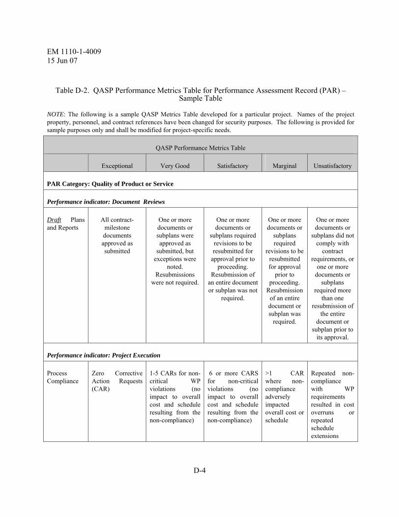
EM 1110-1-4009 15 Jun 07
D-4
Table D-2. QASP Performance Metrics Table for Performance Assessment Record (PAR) – Sample Table
NOTE: The following is a sample QASP Metrics Table developed for a particular project. Names of the project property, personnel, and contract references have been changed for security purposes. The following is provided for sample purposes only and shall be modified for project-specific needs.
QASP Performance Metrics Table
Exceptional Very Good Satisfactory Marginal Unsatisfactory
PAR Category: Quality of Product or Service
Performance indicator: Document Reviews
Draft Plans and Reports
All contract-milestone documents approved as submitted
One or more documents or subplans were approved as
submitted, but exceptions were
noted. Resubmissions
were not required.
One or more documents or
subplans required revisions to be resubmitted for
approval prior to proceeding.
Resubmission of an entire document or subplan was not
required.
One or more documents or
subplans required
revisions to be resubmitted for approval
prior to proceeding.
Resubmission of an entire document or subplan was
required.
One or more documents or
subplans did not comply with
contract requirements, or
one or more documents or
subplans required more
than one resubmission of
the entire document or
subplan prior to its approval.
Performance indicator: Project Execution
Process Compliance
Zero Corrective Action Requests (CAR)
1-5 CARs for non-critical WP violations (no impact to overall cost and schedule resulting from the non-compliance)
6 or more CARS for non-critical violations (no impact to overall cost and schedule resulting from the non-compliance)
>1 CAR where non-compliance adversely impacted overall cost or schedule
Repeated non-compliance with WP requirements resulted in cost overruns or repeated schedule extensions
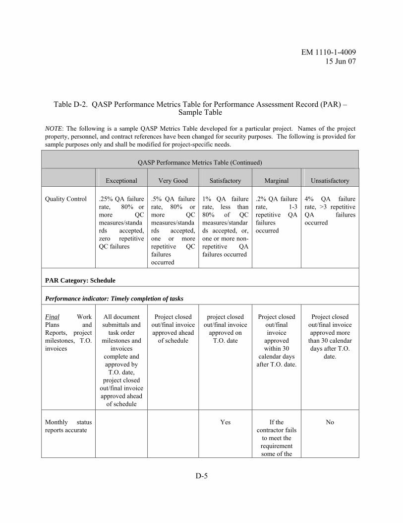
EM 1110-1-4009 15 Jun 07
D-5
Table D-2. QASP Performance Metrics Table for Performance Assessment Record (PAR) – Sample Table
NOTE: The following is a sample QASP Metrics Table developed for a particular project. Names of the project property, personnel, and contract references have been changed for security purposes. The following is provided for sample purposes only and shall be modified for project-specific needs.
QASP Performance Metrics Table (Continued)
Exceptional Very Good Satisfactory Marginal Unsatisfactory
Quality Control .25% QA failure rate, 80% or more QC measures/standards accepted, zero repetitive QC failures
.5% QA failure rate, 80% or more QC measures/standards accepted, one or more repetitive QC failures occurred
1% QA failure rate, less than 80% of QC measures/standards accepted, or, one or more non-repetitive QA failures occurred
.2% QA failure rate, 1-3 repetitive QA failures occurred
4% QA failure rate, >3 repetitive QA failures occurred
PAR Category: Schedule
Performance indicator: Timely completion of tasks
Final Work Plans and Reports, project milestones, T.O. invoices
All document submittals and
task order milestones and
invoices complete and approved by T.O. date,
project closed out/final invoice approved ahead
of schedule
Project closed out/final invoice approved ahead
of schedule
project closed out/final invoice
approved on T.O. date
Project closed out/final invoice
approved within 30
calendar days after T.O. date.
Project closed out/final invoice approved more
than 30 calendar days after T.O.
date.
Monthly status reports accurate
Yes If the contractor fails
to meet the requirement some of the
No

EM 1110-1-4009 15 Jun 07
D-6
Table D-2. QASP Performance Metrics Table for Performance Assessment Record (PAR) – Sample Table
NOTE: The following is a sample QASP Metrics Table developed for a particular project. Names of the project property, personnel, and contract references have been changed for security purposes. The following is provided for sample purposes only and shall be modified for project-specific needs.
QASP Performance Metrics Table (Continued)
Exceptional Very Good Satisfactory Marginal Unsatisfactory time and
corrects the performance
when required by the
Contracting Officer.
Delays to schedule caused by contractor or other causes identified, in writing, in a timely manner to apply acceptable corrective actions.
Yes If the contractor fails
to meet the requirement some of the
time and corrects the performance
when required by the
Contracting Officer.
No
PAR Category: Cost Control
Performance indicator: No unauthorized cost overruns
Unauthorized cost overruns
No Yes
Total Project Costs
Total contract invoices less than 70% of initial T.O. authorized
amount
Total contract invoices greater
than 70% but less than 90%of
initial T.O. authorized
amount
Total contract invoices between 90% and 100% of initial T.O.
authorized amount
Total contract invoices
greater than 100% but less than 110% of initial T.O. authorized
amount
Total contract invoices greater
than 110% or less than 120% of T.O. authorized amount

EM 1110-1-4009 15 Jun 07
D-7
Table D-2. QASP Performance Metrics Table for Performance Assessment Record (PAR) – Sample Table
NOTE: The following is a sample QASP Metrics Table developed for a particular project. Names of the project property, personnel, and contract references have been changed for security purposes. The following is provided for sample purposes only and shall be modified for project-specific needs.
QASP Performance Metrics Table (Continued)
Exceptional Very Good Satisfactory Marginal Unsatisfactory
Performance indicator: Monthly cost report
Monthly cost reports accurate
Yes If the contractor fails
to meet the requirement some of the
time and corrects the performance
when required by the
Contracting Officer.
No
Performance indicator: Impacts to cost
Impacts caused by contractor or other causes identified, in writing, in a timely manner to apply acceptable corrective actions.
Yes If the contractor fails
to meet the requirement some of the
time and corrects the performance
when required by the
Contracting Officer.
No

EM 1110-1-4009 15 Jun 07
D-8
Table D-2. QASP Performance Metrics Table for Performance Assessment Record (PAR) – Sample Table
NOTE: The following is a sample QASP Metrics Table developed for a particular project. Names of the project property, personnel, and contract references have been changed for security purposes. The following is provided for sample purposes only and shall be modified for project-specific needs.
QASP Performance Metrics Table (Continued)
Exceptional Very Good Satisfactory Marginal Unsatisfactory
PAR Category: Business Relations
Performance indicator: Met contractual responsibilities
Corrective Actions taken were timely and effective (Refer to CARs issued to contractor)
Yes If the contractor fails
to meet the requirement some of the
time and corrects the performance
when required by the
Contracting Officer.
No
Performance indicator: Professional and Ethical Conduct
Meetings and correspondences with public, project delivery team and other stakeholders
Zero letters of reprimand, grievances, or formal complaints AND one or more unsolicited letters of commendation
Zero letters of reprimand, grievances, or formal complaints
One letter of reprimand, grievance or formal complaint that was resolved through negotiation
More than one letter of reprimand, grievance or formal complaint that were resolved through negotiation OR removal of one or more project personnel as a result of a letter of reprimand, grievance or formal complaint.

EM 1110-1-4009 15 Jun 07
D-9
Table D-2. QASP Performance Metrics Table for Performance Assessment Record (PAR) – Sample Table
NOTE: The following is a sample QASP Metrics Table developed for a particular project. Names of the project property, personnel, and contract references have been changed for security purposes. The following is provided for sample purposes only and shall be modified for project-specific needs.
QASP Performance Metrics Table (Continued)
Exceptional Very Good Satisfactory Marginal Unsatisfactory
Performance indicator: Customer has overall satisfaction with work performed
Customer survey results for rating period
5.0-6.0 4.0-4.9 3.0-3.9 2.0-2.9 <2.0
Performance indicator: Personnel responsive and cooperative
Key personnel responsive, and cooperative
Always Most Times Almost Never
PAR Category: Management of Key Personnel and Resources
Performance indicator: Personnel knowledgeable and effective in their areas of responsibility
Personnel assigned to tasks
All personnel proposed by
contractor were assigned to
project, some personnel were substituted by
higher qualified individuals.
All personnel proposed by
contractor were assigned to
project, some personnel were substituted by
equally qualified individuals.
All personnel proposed by
contractor were assigned to
project, some personnel were substituted by lesser qualified
individuals.
Performance indicator: Personnel able to manage resources efficiently
Instances when resource management had negative impact on project
0 1-2 3-4 5-6 >6

EM 1110-1-4009 15 Jun 07
D-10
Table D-2. QASP Performance Metrics Table for Performance Assessment Record (PAR) – Sample Table
NOTE: The following is a sample QASP Metrics Table developed for a particular project. Names of the project property, personnel, and contract references have been changed for security purposes. The following is provided for sample purposes only and shall be modified for project-specific needs.
QASP Performance Metrics Table (Continued)
Exceptional Very Good Satisfactory Marginal Unsatisfactory execution
PAR Category: Safety
Performance indicator: Accidents and Violations
*Number of Class A Accidents, contractor at fault
0 1 or more
*Major safety violations
0 1 >1
*Minor safety violations
1 2-4 >4
*From Section C of Basic contract #A123BC-00-D-0000, Amendment 0001 (may be included but are not limited to these)
The following guidelines are provided for issuing ratings that are subjective in nature, these ratings will be supported by the weight of evidence documented during the government's surveillance efforts:
Exceptional: Performance meets contractual requirements and exceeds many to the Government's benefit. The contractual performance of the element or sub-element being assessed was accomplished with few minor problems for which corrective actions taken by the contractor were highly effective.
Very Good: Performance meets contractual requirements and exceeds some to the Government's benefit. The contractual performance of the element or sub-element being assessed was accomplished with some minor problems for which corrective actions taken by the contractor were effective.

EM 1110-1-4009 15 Jun 07
D-11
Satisfactory: Performance meets contractual requirements. The contractual performance of the element or sub-element contains some minor problems for which corrective actions taken by the contractor appear or were satisfactory.
Marginal: Performance does not meet all contractual requirements. The contractual performance of the element or sub-element being assessed reflects a serious problem for which the contractor has not yet identified corrective actions. The contractor's proposed actions appear only marginally effective or were not fully implemented.
Unsatisfactory: Performance does not meet most contractual requirements and recovery is not likely in a timely manner. The contractual performance of the element or sub-element contains serious problems for which the contractor's corrective actions appear or were ineffective.

EM 1110-1-4009 15 Jun 07
D-12
This page intentionally left blank

EM 1110-1-4009 15 Jun 07
E-1
APPENDIX E SURVEILLANCE ACTIVITIES TABLE
E-1. General. The following appendix provides: (1) instructions for documenting surveillance activities; and (2) a sample Surveillance Activities Table. The sample Surveillance Activities Table was completed for a particular project and is provided for informational purposes only and shall be modified for project-specific needs.
E-2. Instructions for Documenting Surveillance Activities Table.
a. General. The Surveillance Activities Table is used to document the project delivery team's QA activities. Results of these government activities fulfill two primary functions:
(1) Assures that project objectives have been met, and
(2) Supports annual and/or closeout contractor performance ratings in the PPIMS.
b. Column 1 - Definable Feature of Work. Definable features of work are those products or processes that can be identified as having results that can be measured. For the purposes of QA Surveillance activities, only those definable features of work that impact the overall quality or safety of the project should be included.
c. Column 2 - Reference - Contract/Task Order requirement or other applicable reference that requires the stated Definable Feature of Work from Column 1.
d. Column 3 - Method of Surveillance - Common accepted surveillance methods are:
(1) Random Sampling: Random Sampling is a statistically based method that assumes receipt of acceptable performance if a given percentage or number of scheduled surveillance activities have found the product or service to be acceptable. If performance is considered marginal or unsatisfactory, the project team should document the discrepancy or finding on a Corrective Action Request (CAR). If performance is satisfactory, very good, or exceptional, the project team should consider adjusting the sample size or sampling frequency. Random sampling is the most appropriate method for frequently recurring tasks. It works best when the number of instances is very large and a statistically valid sample can be obtained.
(2) Periodic Inspection - Periodic inspection (i.e., Weekly, Monthly, Quarterly, etc.) consists of the evaluation of tasks selected on other than a 100% or random basis. It may be appropriate for tasks that occur infrequently, and where 100% inspection is neither required nor practicable. A predetermined plan for inspecting part of the work is established using subjective judgment and analysis of agency resources to decide what work to inspect and how frequently to inspect it. Selecting this tool to determine a contractor's compliance with contract requirements

EM 1110-1-4009 15 Jun 07
E-2
can be quite effective and it allows for assessing confidence in the contractor without consuming a significant amount of time.
(3) 100 Percent Inspection - This is usually the most appropriate method only for infrequent tasks or tasks with stringent performance requirements. With this method, performance is inspected/evaluated at each occurrence. The cost-benefit of one hundred percent inspection should be considered prior to its implementation.
(4) Customer Feedback - Customer feedback is firsthand information from the actual users of the service or product. It should be used to supplement other forms of evaluation and assessment, and it is especially useful for those areas that do not lend themselves to the typical forms of surveillance. However, customer feedback information should be used prudently. Sometimes customer feedback is complaint-oriented, likely to be subjective in nature, and may not always relate to actual requirements of the contract. Such information requires thorough validation.
(5) Third-party Audits - The term "third-party audits" refers to a contractor evaluation made by a third-party organization that is independent of the government and the contractor. All documentation supplied to, and produced by, the third party should be made available to both the government and the contractor.
e. Column 4 - Documentation of Surveillance Activities Performed. Identify the document(s) to be used by the project team to record that specified surveillance activities have been performed and describe the results of those surveillance activities.
f. Column 5 - QA Surveillance Record File. Identify where the Quality Assurance Reports (or other documentation, from Column 4) are filed by the project team. The preferred method is to have a central location or file for all QA Surveillance documentation, but if multiple files/locations (i.e., project team members) will be used, identify them in this column.
g. Column 6 - PPIMS Performance Assessment Record (PAR) Category. This column is used to identify the PAR category under which the associated Definable Feature of Work will be rated. More than one PAR Category may apply to a given Definable Feature of Work. PAR Categories may include, but are not limited to:
(1) Quality of Product or Service - Assess the contractor's conformance to contract requirements, specifications and standards of good workmanship (e.g., commonly accepted technical or professional standards).
(2) Schedule - Assess the timeliness of the contractor against the completion of the contract, task orders, milestones, delivery schedules, administrative requirements, etc. Assess the contractor's adherence to the required delivery schedule by assessing his/her efforts during the assessment period that contribute to or effect the schedule variance.

EM 1110-1-4009 15 Jun 07
E-3
(3) Cost Control - Assess the contractor's effectiveness in forecasting, managing, and controlling contract cost. Assess for all contracts except Firm Fixed Price (FFP) or Firm Fixed Price with Economic Price Adjustment contracts.
(4) Business Relations - Assess the timeliness, completeness, and quality of problem identification, corrective action plans, proposal submittals, the contractor's history of reasonable and cooperative behavior, and customer satisfaction. Assess the contractor's success with timely award and management of subcontracts, including whether the contractor met small/small disadvantaged and women-owned business participation goals. Assess the extent to which the contractor discharges its responsibility for integration and coordination for all activity needed to execute the contract.
(5) Management of Key Personnel - (For Services and Information Technology Business Sectors Only) - Assess the contractor's performance in selecting, retaining, supporting, and replacing, when necessary, key personnel.
(6) Safety- Assess any elements not covered in this section or provide additional comments on the contractor's overall performance level. For MMRP projects, this is where Safety is rated. Assess the contractor's adherence to approved safety plans, explosives/chemical agent safety requirements, and ability to prevent safety related incidents/accidents.
h. Column 7 - Basic Performance Indicators. Performance indicators are the standards and measures by which the project delivery team determines acceptability of contractor performance regarding the associated Definable Feature of Work (Column 1). For example: If "Draft Plans and Reports" is the Definable Feature of Work, then Basic Performance Indicators might be "Plans and Reports are concise and technically accurate, plans are in accordance with applicable regulations, reports are logical and support subsequent decisions." The associated Performance Metric when rating contractor performance might be related to the number and seriousness of comments generated and/or the need for subsequent government reviews.

EM 1110-1-4009 15 Jun 07
E-4
This page intentionally left blank

EM 1110-1-4009 15 Jun 07
E-5
Table E-1. Surveillance Activities Table
(1)
Definable Feature of Work
(Product or Process being Rated)
(Each Definable Feature of Work should have at least one corresponding metric
associated with it.)
(2)
Reference
(Self explanatory)
(3)
Method of Surveillance
(100%, Random Sampling, Periodic-
(i.e., Weekly, Monthly, Quarterly
etc.,)
(4)
Documentation of Surveillance
Activities Performed
(Objective Evidence)
(Identify what documentation will
be generated as evidence that surveillance
activities were conducted)
(5)
QA Surveillance Record File
(e.g. CARs in Contract file, Form-7 comments in PM file, QARs in project engineer files, etc.)
(6)
PPIMS Performance Assessment Record
(PAR) Category
(One or more categories may apply,
but each definable feature of work,
Column 1, must be directly linked to at
least one Performance Metric)
(7)
Basic Performance Indicator(s)
(To be used as the basis for contractor ratings described in the
performance metrics when completing the Contractor
Performance Assessment Record (PAR) in PPIMS)
Project Documents/Submittals
1. Draft Work Plan
2. Draft Final Report
3. Draft Explosives Safety Submissions
T.O. para 3.2 100% review of submitted documents.
CEHNC Form 7, Contracting Officer Transmittal Memo
Official Contract File
Quality of Product or Service
Resubmissions required based on amount and nature of government comments regarding formatting, completeness, technical accuracy, regulatory compliance, conciseness, decisions supported by data.
Work Plan Execution
Technical Management Plan T.O. para. 4.2 Periodic Inspection (Monthly)
Trip Reports, Geophysical QA Report, QAR, Corrective Action Requests (CAR)
Project Engineer and PM Project file
1. Quality Of Product or Service.
2. Management of Key Personnel and Resources
Number and type of Corrective Actions required based on government observation regarding:
1. Compliance with approved plans, personnel knowledgeable and effective regarding their responsibilities,
2. Personnel meeting position qualifications and resources managed efficiently.
Explosives Management Plan DOD 6055.9-STD, EP 385-1-95
Periodic Inspection (Monthly)
QARs, CARs Project Safety Specialist file
1. Safety
2. Quality of Product or Service.
Number of violations and/or accidents and incidents regarding contractor lack of:
1. Compliance with explosives safety

EM 1110-1-4009 15 Jun 07
E-6
Table E-1. Surveillance Activities Table
(1)
Definable Feature of Work
(Product or Process being Rated)
(Each Definable Feature of Work should have at least one corresponding metric
associated with it.)
(2)
Reference
(Self explanatory)
(3)
Method of Surveillance
(100%, Random Sampling, Periodic-
(i.e., Weekly, Monthly, Quarterly
etc.,)
(4)
Documentation of Surveillance
Activities Performed
(Objective Evidence)
(Identify what documentation will
be generated as evidence that surveillance
activities were conducted)
(5)
QA Surveillance Record File
(e.g. CARs in Contract file, Form-7 comments in PM file, QARs in project engineer files, etc.)
(6)
PPIMS Performance Assessment Record
(PAR) Category
(One or more categories may apply,
but each definable feature of work,
Column 1, must be directly linked to at
least one Performance Metric)
(7)
Basic Performance Indicator(s)
(To be used as the basis for contractor ratings described in the
performance metrics when completing the Contractor
Performance Assessment Record (PAR) in PPIMS)
3. Management of Key Personnel and Resources.
requirements, OSHA requirements.
2. Personnel knowledgeable and practicing safe behavior.
3. Personnel meeting position qualifications and resources being managed efficiently.
Quality Control Plan
(QC Reports)
T.O. para. 5.3 and Work Plan Chapter 11
1. GIS-Periodic Inspection
1. Trip Report, CARs, QA Checklist
1. Project GIS manager file
1. Quality of Product or Service.
Number and type of QC and/or QA failures observed or uncorrected regarding:
1. Reporting examples: Line types, symbology, geodatabase integrity.
2. Geodetic Surveying-100% Inspection of QC reports for all submittals
2. Trip Report, CARs, QA Checklist
2. Project Surveyor file
2. Quality of Product or Service.
2. Reporting examples: Loop closures, re-occupations, reporting coordinate systems, datums, units & delivery of data collector files.
3. Geophysical data collection and processing and anomaly reacquisition-100% inspection of
3. CARs, QA Checklist, Geophysical QA Report
3. Project Geophysicist file
3. Quality of Product or Service.
3. Meeting Project DQOs regarding: noise limits, speed limits, processing SNR compliance, appropriate data density & data coverage, blind seed item detections, anomaly reacquisition tolerances, etc.

EM 1110-1-4009 15 Jun 07
E-7
Table E-1. Surveillance Activities Table
(1)
Definable Feature of Work
(Product or Process being Rated)
(Each Definable Feature of Work should have at least one corresponding metric
associated with it.)
(2)
Reference
(Self explanatory)
(3)
Method of Surveillance
(100%, Random Sampling, Periodic-
(i.e., Weekly, Monthly, Quarterly
etc.,)
(4)
Documentation of Surveillance
Activities Performed
(Objective Evidence)
(Identify what documentation will
be generated as evidence that surveillance
activities were conducted)
(5)
QA Surveillance Record File
(e.g. CARs in Contract file, Form-7 comments in PM file, QARs in project engineer files, etc.)
(6)
PPIMS Performance Assessment Record
(PAR) Category
(One or more categories may apply,
but each definable feature of work,
Column 1, must be directly linked to at
least one Performance Metric)
(7)
Basic Performance Indicator(s)
(To be used as the basis for contractor ratings described in the
performance metrics when completing the Contractor
Performance Assessment Record (PAR) in PPIMS)
submitted QC reports for all data sets.
4. Environmental Sampling and Chemical Analysis data submittal-100% of each QC submittal.
4. QARs, CARs, QA Checklist
4. Project Chemist file
4. Quality of Product or Service.
4. Data submittals pass Automated Data Review. Meet project DQOs for sampling methods, data analyses and validation.
Explosives Siting Plan ESS (appl. to removal/remedial actions), DOD 6055.9-STD, DA Pam 385-64 (appl. to active installations)
Periodic inspection of field operations (Monthly)
Trip Reports, QARs, CARs
Project Safety Specialist file
Safety Number and type of violations regarding compliance with explosives safety requirements.
Geophysical Investigation Plan
T.O. para. 6.3 and work plan chapter 5
Periodic inspection of field operations (Monthly)
Trip Reports, Geophysical QA Report
Project Geophysicist file
1. Quality Of Product or Service.
2. Management of Key Personnel and Resources
Number and type of corrective action requests based on government observation regarding contractor:
1. Compliance with approved plans, personnel knowledgeable and effective regarding their responsibilities,
2. Personnel meet position qualification and resources managed efficiently.

EM 1110-1-4009 15 Jun 07
E-8
Table E-1. Surveillance Activities Table
(1)
Definable Feature of Work
(Product or Process being Rated)
(Each Definable Feature of Work should have at least one corresponding metric
associated with it.)
(2)
Reference
(Self explanatory)
(3)
Method of Surveillance
(100%, Random Sampling, Periodic-
(i.e., Weekly, Monthly, Quarterly
etc.,)
(4)
Documentation of Surveillance
Activities Performed
(Objective Evidence)
(Identify what documentation will
be generated as evidence that surveillance
activities were conducted)
(5)
QA Surveillance Record File
(e.g. CARs in Contract file, Form-7 comments in PM file, QARs in project engineer files, etc.)
(6)
PPIMS Performance Assessment Record
(PAR) Category
(One or more categories may apply,
but each definable feature of work,
Column 1, must be directly linked to at
least one Performance Metric)
(7)
Basic Performance Indicator(s)
(To be used as the basis for contractor ratings described in the
performance metrics when completing the Contractor
Performance Assessment Record (PAR) in PPIMS)
Environmental Sampling and Chemical Analyses
Section C, Chapter 2, Sub-section 2.8, Chapter 4, Sub-section 4.5, T.O. para 3.2
Periodic Inspection (during sampling events)
100% review of all DID MR005-10 Section 1.4 submittals except the Chemistry Data Package.
5% review of the Chemistry Data Package
Trip reports, CARs, QARs, and/or statements of reviewed chemical data
Project Chemist file
Quality of Product or Service.
Management of Key Personnel and Resources
Data submittals pass Automated Data Review. Meet project DQOs for sampling methods, data analyses and validation. Number and type of corrective action requests based on government observation regarding contractor: Compliance with approved plans, personnel knowledgeable and effective regarding their responsibilities.
Personnel meet position qualification and resources managed efficiently.
Other Definable Features of Work to be included based on project objectives and project delivery team needs.
Cost/Schedule
Project Management: Cost and Schedule Control/Reporting
T.O. para. 6.6 100% of weekly status reports
PM checklist PM file 1. Schedule
2. Cost Control
Number of instances of contractor impacts on cost and schedule attributable to the contractor, impacts not identified, and unauthorized cost overruns.

EM 1110-1-4009 15 Jun 07
E-9
Table E-1. Surveillance Activities Table
(1)
Definable Feature of Work
(Product or Process being Rated)
(Each Definable Feature of Work should have at least one corresponding metric
associated with it.)
(2)
Reference
(Self explanatory)
(3)
Method of Surveillance
(100%, Random Sampling, Periodic-
(i.e., Weekly, Monthly, Quarterly
etc.,)
(4)
Documentation of Surveillance
Activities Performed
(Objective Evidence)
(Identify what documentation will
be generated as evidence that surveillance
activities were conducted)
(5)
QA Surveillance Record File
(e.g. CARs in Contract file, Form-7 comments in PM file, QARs in project engineer files, etc.)
(6)
PPIMS Performance Assessment Record
(PAR) Category
(One or more categories may apply,
but each definable feature of work,
Column 1, must be directly linked to at
least one Performance Metric)
(7)
Basic Performance Indicator(s)
(To be used as the basis for contractor ratings described in the
performance metrics when completing the Contractor
Performance Assessment Record (PAR) in PPIMS)
Business Relations
Meeting preparation and professional conduct
Customer Feedback Email, letters, customer survey forms
PM file 1. Quality of Product or Service
2. Business Relations
Number of customer complaints regarding:
1. Personnel prepared and knowledgeable in areas of expertise.
2. Professional and ethical conduct.
Management of Key Personnel
Project Management: Personnel
Periodic Inspection (Monthly, or upon change in personnel)
Trip report, QARs, CARs
Project Safety Specialist or PM file
Management of Key Personnel and Resources
Number of instances regarding contractor personnel and their qualifications for filling key positions/functions.

EM 1110-1-4009 15 Jun 07
E-10
This page intentionally left blank. 1

EM 1110-1-4009 15 Jun 07
F-1
APPENDIX F CORRECTIVE ACTION REQUEST (CAR)
F-1. General. The following includes a: (1) blank CAR form and (2) sample CAR form that has been completed for a particular project. The sample CAR form is provided for informational purposes only and shall be modified for project-specific needs.
Table F-1. Blank CAR Form
CORRECTIVE ACTION REQUEST | NO. (1,2,3, etc. for the T.O.)
USACE Representative:
Date Issued:
Issued to: (Contractor)
Response Due: (Based on type of nonconformance)
Contract # and T.O. #
Project Name/Location:
Nonconformance Type (circle one): Critical Major Minor
Description of Condition Found:
Apparent Cause:
(The Contractor will provide the following information to the Contracting Officer and USACE PM by the “Response Due” date above. Please contact the USACE Representative listed above if you have any questions)
Actual Cause: (Contractor will investigate and determine cause of condition reported above. Actual cause should be stated as specifically as possible)
Action Taken to Correct Condition: (Corrective Action should address root cause, not the symptom)
Action Taken to Prevent Recurrence:
Action Taken to Monitor Effectiveness of Corrective Action: (Generate data as proof. State the monitoring method put in place and who is responsible for reviewing data.)
Contractor Representative Signature/Title/Date Signed: (Form must be signed before returning)

EM 1110-1-4009 15 Jun 07
F-2
CORRECTIVE ACTION REQUEST | NO. (1,2,3, etc. for the T.O.)
(USACE Project Team Use Only)
Review of Corrective Action:
1) Has condition improved? ___ Yes ___ No
2) Additional corrective action required? ___ Yes ___ No
Comments:
Completed form provided to Contracting Officer: (Date)
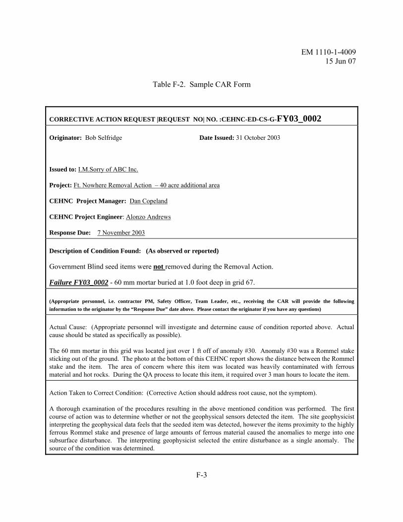
EM 1110-1-4009 15 Jun 07
F-3
Table F-2. Sample CAR Form
CORRECTIVE ACTION REQUEST |REQUEST NO| NO. :CEHNC-ED-CS-G-FY03_0002
Originator: Bob Selfridge Date Issued: 31 October 2003
Issued to: I.M.Sorry of ABC Inc.
Project: Ft. Nowhere Removal Action – 40 acre additional area
CEHNC Project Manager: Dan Copeland
CEHNC Project Engineer: Alonzo Andrews
Response Due: 7 November 2003
Description of Condition Found: (As observed or reported)
Government Blind seed items were not removed during the Removal Action.
Failure FY03_0002 - 60 mm mortar buried at 1.0 foot deep in grid 67.
(Appropriate personnel, i.e. contractor PM, Safety Officer, Team Leader, etc., receiving the CAR will provide the following information to the originator by the “Response Due” date above. Please contact the originator if you have any questions)
Actual Cause: (Appropriate personnel will investigate and determine cause of condition reported above. Actual cause should be stated as specifically as possible).
The 60 mm mortar in this grid was located just over 1 ft off of anomaly #30. Anomaly #30 was a Rommel stake sticking out of the ground. The photo at the bottom of this CEHNC report shows the distance between the Rommel stake and the item. The area of concern where this item was located was heavily contaminated with ferrous material and hot rocks. During the QA process to locate this item, it required over 3 man hours to locate the item.
Action Taken to Correct Condition: (Corrective Action should address root cause, not the symptom).
A thorough examination of the procedures resulting in the above mentioned condition was performed. The first course of action was to determine whether or not the geophysical sensors detected the item. The site geophysicist interpreting the geophysical data feels that the seeded item was detected, however the items proximity to the highly ferrous Rommel stake and presence of large amounts of ferrous material caused the anomalies to merge into one subsurface disturbance. The interpreting geophysicist selected the entire disturbance as a single anomaly. The source of the condition was determined.

EM 1110-1-4009 15 Jun 07
F-4
CORRECTIVE ACTION REQUEST |REQUEST NO| NO. :CEHNC-ED-CS-G-FY03_0002
The geophysicist went through the Task Order data looking for similar anomalies. These were then looked at by the geophysicist and the UXOQC to determine if additional work needed to be done in those
locations. Six additional anomalies were found that needed further investigation.
Action Taken to Prevent Recurrence: Intrusive teams have been instructed to verify that a 3-foot
radius about the selected location has been cleared. Regardless if a large metallic surface item is present. In addition, interpreting geophysicist has been instructed to select more than the one target location on large subsurface anomalies. This will encourage the intrusive teams to continue their investigation until the anomaly (or anomalies) have been uncovered.
Action Taken to Monitor Effectiveness of Corrective Action: (Generate data as proof. State the monitoring method put in place and who is responsible for reviewing data.)
The Internal quality control personnel will work closely with the intrusive teams to verify that the preventive recurrence actions are being applied.
Team Manager Signature/Title/Date Signed: (Form must be signed before returning)
I. M. Sorry / I. M. Sorry/ Project Manager/ 4 November 2003
(Government Use Only)
Review of Corrective Action: 1) Has condition improved? X Yes ___ No 2) Additional corrective action required? ___ Yes _X__ No
Comments:

EM 1110-1-4009 15 Jun 07
F-5
CORRECTIVE ACTION REQUEST |REQUEST NO| NO. :CEHNC-ED-CS-G-FY03_0002
Item Item ID Depth Dec Inc Grid SW* SE* NE* NW*
60mm CEHNC-H07 1' E-W H 67 57' 80'8" 85'10" 64'3"
* - measured tape distances from corners of grid to item.

EM 1110-1-4009 15 Jun 07
F-6
This page intentionally left blank

EM 1110-1-4009 15 Jun 07
G-1
APPENDIX G GENERIC ON-SITE QA CHECKLIST
Project Name/Contract No. _________________________________________________
Audit Date (Start): ____________________ Audit Date (End): ____________________
CHECKPOINTS:
1. Review Scope of Work (DO/TO & WP) YES NO N/A COMMENTS
a. Objectives Clearly Identified
b. Check for Changes to WP & Up To Date
c. Proper Depth of Clearance Identified
d. Proper Target Ordnance Identified
e. Detection & Target Depth(s) Specified
f. Exclusion Zone Identified in WP
2. Documentation Requirements YES NO N/A COMMENTS
a. Notice to Proceed from KO
b. Approval Letter for Work Plan/SSHP
c. Approval Letter, FAA (If Required)
d. Certificate of Grounding, Lightning Protection (if required)
e. Explosive Permits/License (if required)
f. GFE Transfer Documentation (if required)
g. Approval Letter, Public/Personnel Withdraw Distance (e.g., 1 Frag in 600 sq. ft.)
i. Dig Permits for Utilities (if required)
j. Current copy of the Work Plan on site. Review the new contract to determine if approval of the work plan is required. If not, then delete the requirement to have an approval letter on site
3. CEHNC QA Files Established YES NO N/A COMMENTS
a. Quality Assurance Reports
b. Approval Letter’s (NTP, Personnel & WP/SSHP) for Contractor Operations
c. Weekly Contractor Reports SUXOS/QC

EM 1110-1-4009 15 Jun 07
G-2
(if provided)
4. Site-Specific Safety & Health Plan (SSHP) YES NO N/A COMMENTS
a. Emergency Notification List Posted & Available
b. Emergency Routes/Maps Available & Issued to Each Team
c. Work Task Identified in Hazard Analysis, Approved SSHP
d. MSDS(s) On-Site Approved SSHP
e. Visitors/Safety Briefing Log Current and Updated
f. All Personnel On-Site in the Proper PPE
g. Minimum of Two Personnel On-Site First Aid/CPR Trained, EM 385-1-1, Section 3, Page 19, Paragraph 03.A.02
h. 16-Unit First Aid Kits or Kits Approved by a Licensed Physician in the Ratio of one for every 25 persons or less. EM 385-1-1. Section 3, Page 19, Paragraph 03.A.03
5. Technical Management YES NO N/A COMMENTS
a. Procedures Established for the Discovery of RCWM
b. Procedures Developed for Discovery of MEC which cannot be destroyed in place
c. Project Grid Size, Layout, Lane Width (e.g., 5’ or Less) Established
d. Established Procedures for Changed Site Conditions
e. Organizational Chart current and indicates Assignment, Duties, Responsibilities to include Geophysical Teams
f. Procedures for Reporting and Disposition of MPPEH
g. Procedures Established for Disposal of MEC in Populated/Sensitive Areas
h. Procedures Established for Managing, Reporting, Venting and Disposing of munitions debris and range-related debris.

EM 1110-1-4009 15 Jun 07
G-3
5. Technical Management (Continued) YES NO N/A COMMENTS
i. Additional Task and Procedures being Followed (e.g., PAO, Community Relations, Weekly & Monthly Project Status Reports)
j. Procedures Established for Recording, Reporting and Implementing Lessons Learned
k. Limitations Posed and Ability of Detection System(s) Chosen
l. Proper Use of Geophysical Detections Systems Used
m. Procedures Established for Disposal of MEC in non-populated/non-sensitive areas
6. Facilities. Reference EM 385-1-1 YES NO N/A COMMENTS
a. Adequate Work Space & Facilities (Restrooms, etc.)
b. Good Housekeeping (No Fire Hazards, Tripping Hazards, etc.)
c. Approved and Suitable Containers for Flammable Toxic or Explosive Materials
d. Approved/Adequate Explosive Storage Facilities
e. Fire/Emergency Exits Clear & Unbarred
f. Personnel Limits Maintained
g. Site Security Adequate
h. Toilets. EM 385-1-1, Section 2, Page 14, Paragraph 02.B Toilets
i. Washing Facilities. EM 385-1-1, Section 2, Page 16, Paragraph 02.C Washing Facilities

EM 1110-1-4009 15 Jun 07
G-4
7. Equipment, Reference Approved WP/Manufacture Operators Manual
YES NO N/A COMMENTS
a. Tools Appropriate and Serviceable
b. Proper Personnel Protective Equipment (PPE) Present, Serviceable & Utilized
c. Equipment Calibrated (Last Call Date _____ Next Call Date _______)
d. Survey Equipment Inspected & Serviceable
e. Heavy Equipment Inspected & Serviceable IAW EM 385-1-1, Section 16
1. Are Equipped with at Least One Dry Chemical or CO2 Fire Extinguisher-Minimum rating of 5-BC – IAW EM 385-1-1, Section 16
f. Two Separate Means of Communications, Radio(s) Cell Phone, Land Line(s)
g. Geophysical Equipment On-Hand & Serviceable
8. Explosive Storage Requirements. Reference EP 1110-1-18
YES NO N/A COMMENTS
a. Proper Storage Containers Type 2 Magazines conforming to standards set forth in Section 55.206 of ATFP 5400.7, AFT Explosives Law and Regulations.
b. Placards. Each magazine will display the placards required by Department of Transportation (DOT) regulations in accordance with DOD 6055.9-STD and Department of the Army Pamphlet (DA Pam) 385-64 for Hazard Division of MEC stored in the magazine.
c. Explosive Compatibility Groups. Segregated into the appropriate hazard division/storage compatibility group criteria listed in Chapter 3, DOD 6055.9-STD.
d. Physical Security. Contractor shall conduct and document physical security survey. The survey is to determine if fencing or guards are required.
e. Locks. Shall meet the standards listed in Section 55.208 (a) (4), ATFP 5400.7.

EM 1110-1-4009 15 Jun 07
G-5
8. Explosive Storage Requirements. Reference EP 1110-1-18 (Cont’d)
YES NO N/A COMMENTS
f. A key control system will be documented in the Work Plan, EP 1110-1-18.
g. Lightning Protection. Magazine constructed of metal that has 3/16 inch steel or thicker in accordance with National Fire Protection Association (NFPA) 780.
h. Lightning Protection. Magazine grounded in accordance with NFPA.
i. Lightning Protection. Magazine is located at least 6.5 feet from the nearest fence.
j. Lightning Protection. BRAC, IRP, FUDS and Active Installation will meet the provisions of DOD 6055.9-STD. Army installations will also meet the provisions of DA Pam 385-64.
k. Fire Protection. Extinguishers of appropriate size (minimum 10 BC) and type will be located in all explosives storage facilities.
l. Explosive Limits Maintained. .
m. Waiver. MACOM approval for storage of commercial of explosives on-site (if required).
9. Explosive Management Plan. Reference Approved WP/49 CFR
YES NO N/A COMMENTS
a. Signature Authority On-Hand
b. Periodic Inventories Conducted On-Schedule
c. Accountability Records Maintained
d. Lost/Stolen Reporting Procedures in Place
e. Final Disposition Procedures Documented
f. Key Control/Security
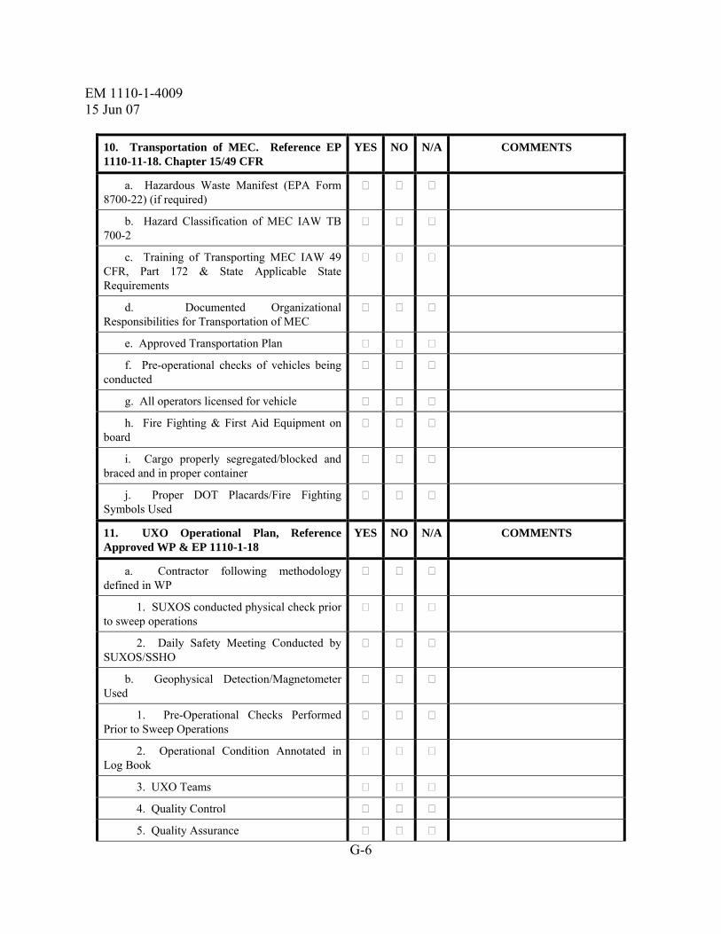
EM 1110-1-4009 15 Jun 07
G-6
10. Transportation of MEC. Reference EP 1110-11-18. Chapter 15/49 CFR
YES NO N/A COMMENTS
a. Hazardous Waste Manifest (EPA Form 8700-22) (if required)
b. Hazard Classification of MEC IAW TB 700-2
c. Training of Transporting MEC IAW 49 CFR, Part 172 & State Applicable State Requirements
d. Documented Organizational Responsibilities for Transportation of MEC
e. Approved Transportation Plan
f. Pre-operational checks of vehicles being conducted
g. All operators licensed for vehicle
h. Fire Fighting & First Aid Equipment on board
i. Cargo properly segregated/blocked and braced and in proper container
j. Proper DOT Placards/Fire Fighting Symbols Used
11. UXO Operational Plan, Reference Approved WP & EP 1110-1-18
YES NO N/A COMMENTS
a. Contractor following methodology defined in WP
1. SUXOS conducted physical check prior to sweep operations
2. Daily Safety Meeting Conducted by SUXOS/SSHO
b. Geophysical Detection/Magnetometer Used
1. Pre-Operational Checks Performed Prior to Sweep Operations
2. Operational Condition Annotated in Log Book
3. UXO Teams
4. Quality Control
5. Quality Assurance
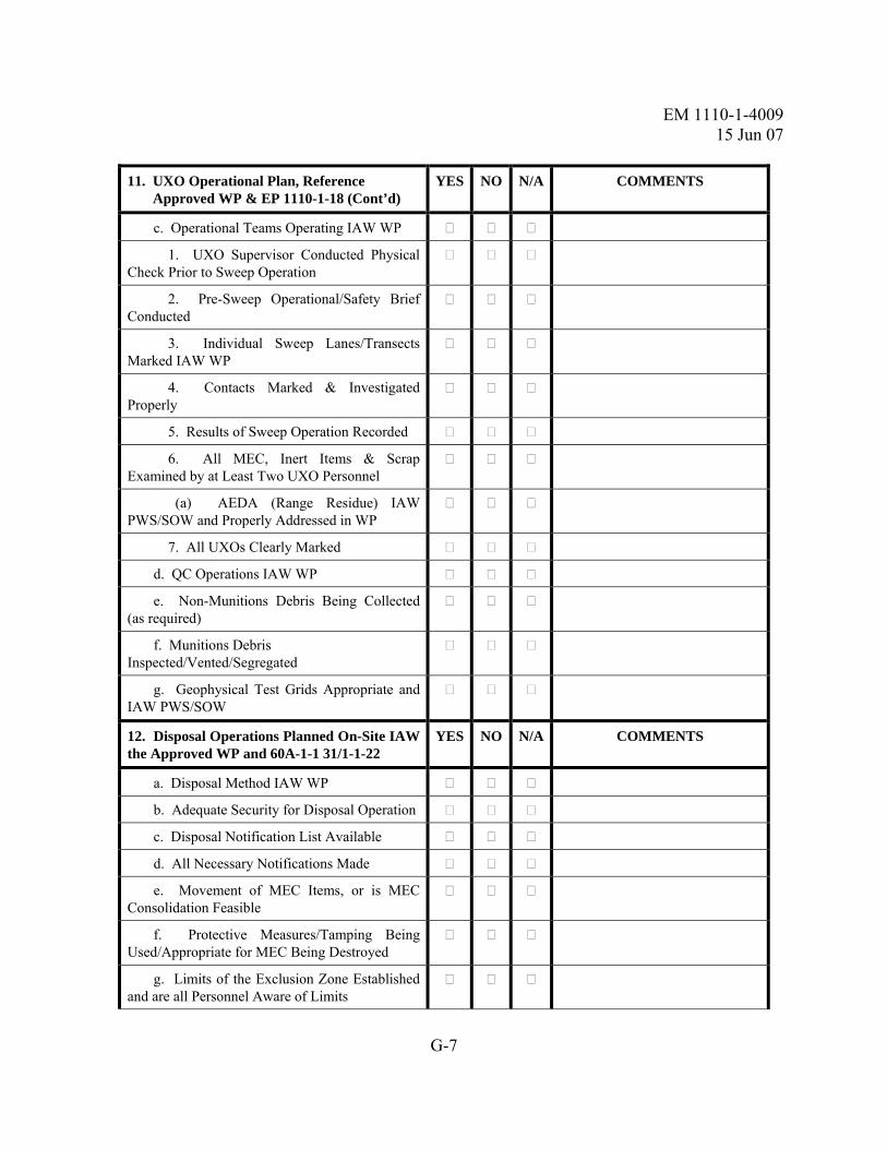
EM 1110-1-4009 15 Jun 07
G-7
11. UXO Operational Plan, Reference Approved WP & EP 1110-1-18 (Cont’d)
YES NO N/A COMMENTS
c. Operational Teams Operating IAW WP
1. UXO Supervisor Conducted Physical Check Prior to Sweep Operation
2. Pre-Sweep Operational/Safety Brief Conducted
3. Individual Sweep Lanes/Transects Marked IAW WP
4. Contacts Marked & Investigated Properly
5. Results of Sweep Operation Recorded
6. All MEC, Inert Items & Scrap Examined by at Least Two UXO Personnel
(a) AEDA (Range Residue) IAW PWS/SOW and Properly Addressed in WP
7. All UXOs Clearly Marked
d. QC Operations IAW WP
e. Non-Munitions Debris Being Collected (as required)
f. Munitions Debris Inspected/Vented/Segregated
g. Geophysical Test Grids Appropriate and IAW PWS/SOW
12. Disposal Operations Planned On-Site IAW the Approved WP and 60A-1-1 31/1-1-22
YES NO N/A COMMENTS
a. Disposal Method IAW WP
b. Adequate Security for Disposal Operation
c. Disposal Notification List Available
d. All Necessary Notifications Made
e. Movement of MEC Items, or is MEC Consolidation Feasible
f. Protective Measures/Tamping Being Used/Appropriate for MEC Being Destroyed
g. Limits of the Exclusion Zone Established and are all Personnel Aware of Limits

EM 1110-1-4009 15 Jun 07
G-8
12. Disposal Operations Planned On-Site IAW the Approved WP and 60A-1-1 31/1-1-22 (Cont’d)
YES NO N/A COMMENTS
h. Disposal Procedures
1. Misfire Procedures Properly Performed (Electric)
2. Misfire Procedures Properly Performed (Non-Electric)
13. Location Survey & Mapping Plan. Reference Contract DIDs
YES NO N/A COMMENTS
a. Professional Land Surveyor
b. Surveyors Received Safety Briefing
c. UXO Escort Provided
d. Grid Stake, Locations Swept with Geophysical Equipment prior to Driving Stakes
e. Survey Notes Being Recorded
14. Quality Control Plan. Reference PWS/SOW/DID(s)
YES NO N/A COMMENTS
a. QC Operational/Checks Being Conducted IAW WP
b. QC Grid/Transect Established IAW WP
c. Results of QC Checks Being Recorded
d. Pass/Fail Criteria Clearly Defined IAW PWS/SOW
15. Vegetation Removal Reference WP/SSHP & OSHA Req.
YES NO N/A COMMENTS
a. Vegetation Removal & Localized, if required
b. Equipment Operation to Prevent Impact with Possible Surface UXO
c. Cutting does not Present Impalement Hazard
d. UXO Personnel Monitoring Cutting Operation
e. UXO Discovered Marked/Handled Appropriately
f. Equipment Being Operated Safely & IAW

EM 1110-1-4009 15 Jun 07
G-9
Equipment Operators Manual/WP
16. Munition Constituents (MC) Sampling and Analysis Plan, if required
YES NO N/A COMMENTS
a. Key Personnel Identified
b. Quality Assurance Responsibilities Identified
c. Procedures for Collection of Samples
d. Local Carrier Location Identified

EM 1110-1-4009 15 Jun 07
G-10
This page intentionally left blank

EM 1110-1-4009 15 Jun 07
H-1
APPENDIX H EE/CA WORK PLAN REVIEW MATRIX
H-1. General. The following is a sample EE/CA Work Plan Review Matrix but may be modified for a particular response process (e.g., RI, RI/FS). The matrix is to identify the individual responsible for a specific discipline to help focus document reviews (e.g., any comments on a particular specialty should be filtered through the individual assigned/responsible for that specialty). Although the following provides what documents individuals are responsible for, it does not preclude one from reviewing other documents and raising questions of concern.
Chapter
PDT Member
DC POC*
PE**
Geo
OE Safety
Sys Safety
Chemist
References/Special Notes
Chapter 1
R/A
Project Authorization
Purpose/Scope
WP Organization
Project Location
Site Description
Site History
Land Use
Previous Investigations
Summary of MEC Risk R C

EM 1110-1-4009 15 Jun 07
H-2
Chapter
PDT Member
DC POC*
PE**
Geo
OE Safety
Sys Safety
Chemist
References/Special Notes
Chapter 2
R/A
Project Objectives
Project Organization
Project Personnel
Communications/Reporting
Deliverables
Schedule
Reporting
Costing/Billing
Public Relations
Subcontractor Management
Management of Field Ops R

EM 1110-1-4009 15 Jun 07
H-3
Chapter
PDT Member
DC POC*
PE**
Geo
OE Safety
Sys Safety
Chemist
References/Special Notes
Chapter 3 R/A
Overall Approach to EE/CA C
ID of Areas of Concern C
GPO Plan and Report C
Geophysical Investigation Plan C R
Surveys/Mapping Plans C
GIS Plan C
Intrusive Investigation R R R
IDW Plan R C
Risk Analysis C
Institutional Controls Analysis C
Recurring Review Plan C

EM 1110-1-4009 15 Jun 07
H-4
Chapter
PDT Member
DC POC*
PE**
Geo
OE Safety
Sys Safety
Chemist
References/Special Notes
Chapter 4 R/A
QC Plan C R R
Chapter 5 R/A
Explosives Management Plan C
Chapter 6
Explosives Siting Plan C
Chapter 7 R/A
Environmental Protection Plan C
Chapter 8 R/A
Property Management Plan C
Chapter 9 R/A
IHF Siting Plan (RCWM) R C
Chapter 10 R/A
Physical Security Plan (RCWM)
R R

EM 1110-1-4009 15 Jun 07
H-5
Chapter
PDT Member
DC POC*
PE**
Geo
OE Safety
Sys Safety
Chemist
References/Special Notes
Chapter 11 R/A
References R R
Appendix A R/A
PWS/SOW R R
Appendix B R/A
Site Maps R R
Appendix C R/A
Local POCs R R
Appendix D R/A
SSHP R C
Appendix E R/A
Environmental SAP C
Appendix F R/A
Contractor Forms R R
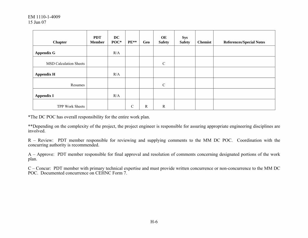
EM 1110-1-4009 15 Jun 07
H-6
Chapter
PDT Member
DC POC*
PE**
Geo
OE Safety
Sys Safety
Chemist
References/Special Notes
Appendix G R/A
MSD Calculation Sheets C
Appendix H R/A
Resumes C
Appendix I R/A
TPP Work Sheets C R R
*The DC POC has overall responsibility for the entire work plan.
**Depending on the complexity of the project, the project engineer is responsible for assuring appropriate engineering disciplines are involved.
R – Review: PDT member responsible for reviewing and supplying comments to the MM DC POC. Coordination with the concurring authority is recommended.
A – Approve: PDT member responsible for final approval and resolution of comments concerning designated portions of the work plan.
C – Concur: PDT member with primary technical expertise and must provide written concurrence or non-concurrence to the MM DC POC. Documented concurrence on CEHNC Form 7.

EM 1110-1-4009 15 Jun 07
I-1
APPENDIX I EE/CA REPORT REVIEW MATRIX
I-1. General. The following is a sample EE/CA Report Review Matrix but may be modified for a particular response process (e.g., RI, RI/FS). The matrix is to identify the individual responsible for a specific discipline to help focus document reviews (e.g., any comments on a particular specialty should be filtered through the individual assigned/responsible for that specialty). Although the following provides what documents individuals are responsible for, it does not preclude one from reviewing other documents and raising questions of concern. Note also that references included in this sample matrix may have been appropriate for a particular project at the time of publication; however, these references may not be valid thereafter.
Chapter PDT Member
MM DC POC*
PE** Geo OE Safety Chemist*** MM CX References/Special Notes
General (Required by DID)
R/A
Signature of corporate quality rep
R
Engineer certification (FINAL)
R
Executive Summary R/A R R R R
Chapter 1 R
Regulatory framework/auth.
PWS/SOW, TPP worksheets
Purpose/scope PWS/SOW, TPP worksheets

EM 1110-1-4009 15 Jun 07
I-2
Chapter PDT Member
MM DC POC*
PE** Geo OE Safety Chemist*** MM CX References/Special Notes
TPP Team (by name) C R R TPP worksheets
Summary, public participation
Admin record file
Other environmental problems
R R Admin record file
Chapter 2 R/A R PWS/SOW, TPP worksheets
Chapter 3 R/A R PWS/SOW, TPP worksheets
Project team goals C R R
Regulator/stakeholder concerns
C R R
Constraints C R R
ID of response alternatives C R R
Project objectives C R R R
Data Quality Objectives (DQOs)
C R R R

EM 1110-1-4009 15 Jun 07
I-3
Chapter PDT Member
MM DC POC*
PE** Geo OE Safety Chemist*** MM CX References/Special Notes
Chapter 4 R/A R Admin record file, project records
Analysis of historical records
R
Interviews conducted R
Analysis of aerial photography
R
Other investigations performed
R R
Source/nature/extent of MEC
C R R R
Chapter 5 R/A R
CSM and its development C R R EM 1110-1-1200
MEC risk assessment method
C R TPP worksheets
MEC risk assessment C
Level of safety risk that exists
C R

EM 1110-1-4009 15 Jun 07
I-4
Chapter PDT Member
MM DC POC*
PE** Geo OE Safety Chemist*** MM CX References/Special Notes
Chapter 6 R/A R
Response alternatives evaluation
R EP 1110-1-18, para. 9-7
Chapter 7 R/A R
Institutional Control Plan C R
Chapter 8 R/A R
Recommended alternatives C R R
Chapter 9 R/A R
QC methods used C R R R
QC results C R R R Field logs/reports, QARs
Lessons learned C R R R
Appendix A R/A
PWS/SOW R R

EM 1110-1-4009 15 Jun 07
I-5
Chapter PDT Member
MM DC POC*
PE** Geo OE Safety Chemist*** MM CX References/Special Notes
Appendix B R/A
Scrap disposition documents
R
Appendix C R/A
Demo activity tables R
Appendix D R/A R
Institutional analysis and report
R
Appendix E R/A
Cost breakdown R
Appendix F R/A R
Responsiveness Summary C R R
Appendix G R/A R
Recurring Review Plan (Draft)
C R R
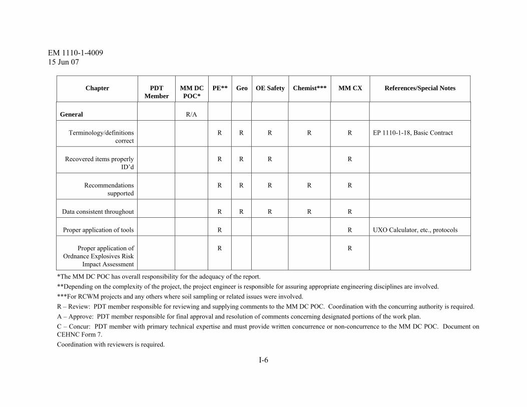
EM 1110-1-4009 15 Jun 07
I-6
Chapter PDT Member
MM DC POC*
PE** Geo OE Safety Chemist*** MM CX References/Special Notes
General R/A
Terminology/definitions correct
R R R R R EP 1110-1-18, Basic Contract
Recovered items properly ID’d
R R R R
Recommendations supported
R R R R R
Data consistent throughout R R R R R
Proper application of tools R R UXO Calculator, etc., protocols
Proper application of Ordnance Explosives Risk
Impact Assessment
R R
*The MM DC POC has overall responsibility for the adequacy of the report. **Depending on the complexity of the project, the project engineer is responsible for assuring appropriate engineering disciplines are involved. ***For RCWM projects and any others where soil sampling or related issues were involved. R – Review: PDT member responsible for reviewing and supplying comments to the MM DC POC. Coordination with the concurring authority is required. A – Approve: PDT member responsible for final approval and resolution of comments concerning designated portions of the work plan. C – Concur: PDT member with primary technical expertise and must provide written concurrence or non-concurrence to the MM DC POC. Document on CEHNC Form 7. Coordination with reviewers is required.

EM 1110-1-4009 15 Jun 07
J-1
APPENDIX J REMOVAL ACTION WORK PLAN REVIEW MATRIX
J-1. General. The following is a sample EE/CA Report Review Matrix but may be modified for a particular response process (e.g., RI, RI/FS). The matrix is to identify the individual responsible for a specific discipline to help focus document reviews (e.g., any comments on a particular specialty should be filtered through the individual assigned/responsible for that specialty). Although the following provides what documents individuals are responsible for, it does not preclude one from reviewing other documents and raising questions of concern. Note also that references included in this sample matrix may have been appropriate for a particular project at the time of publication; however, these references may not be valid thereafter.
Chapter PDT Member
MM DC
POC*
PE** Geo OE Safety
Sys Safety
Chemist References/Special Notes
Chapter 1 R/A
General Information
Site Location
Site History
Topography
Chapter 2 R/A
Technical Management Plan C R R
Chapter 3 R/A
Explosives Management Plan C

EM 1110-1-4009 15 Jun 07
J-2
Chapter PDT Member
MM DC
POC*
PE** Geo OE Safety
Sys Safety
Chemist References/Special Notes
Chapter 4 R/A
Explosives Siting Plan C
Chapter 5 R/A
Geophysical Proveout Plan/Report
C
Chapter 6 R/A
Geophysical Investigation Plan
R C R
Chapter 7 R/A
Location Surveys and Mapping Plan
C R R
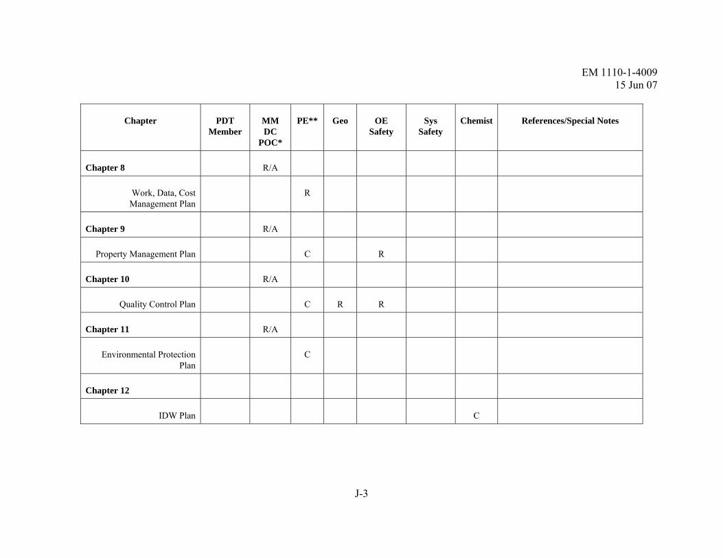
EM 1110-1-4009 15 Jun 07
J-3
Chapter PDT Member
MM DC
POC*
PE** Geo OE Safety
Sys Safety
Chemist References/Special Notes
Chapter 8 R/A
Work, Data, Cost Management Plan
R
Chapter 9 R/A
Property Management Plan C R
Chapter 10 R/A
Quality Control Plan C R R
Chapter 11 R/A
Environmental Protection Plan
C
Chapter 12
IDW Plan C

EM 1110-1-4009 15 Jun 07
J-4
Chapter PDT Member
MM DC
POC*
PE** Geo OE Safety
Sys Safety
Chemist References/Special Notes
Chapter 13 R/A
Geographical Information Systems Plans
C R
Chapter 14
IHF Siting Plan R R
Chapter 15
Physical Security Plan R R
Chapter 16 R/A
References R R R
Appendix A R/A
TO Scope of Work
Appendix B R/A
Site Maps C R R

EM 1110-1-4009 15 Jun 07
J-5
Chapter PDT Member
MM DC
POC*
PE** Geo OE Safety
Sys Safety
Chemist References/Special Notes
Appendix C R/A
Local Points of Contact C R TPP Worksheets, Meeting Minutes
Appendix D R/A
SSHP R C
Appendix E R/A
Environmental SAP R C
Appendix F
QC Log R C
Safety Mtg Attendance Log C
Site Visitors Log C
Safety Inspections Log C
Daily Report of MEC Operations
C

EM 1110-1-4009 15 Jun 07
J-6
Chapter PDT Member
MM DC
POC*
PE** Geo OE Safety
Sys Safety
Chemist References/Special Notes
Explosives Accountability Forms
C
Appendix G
MSD Calculation Sheets C
Appendix H
Resumes C
*The MM DC POC has overall responsibility for the entire work plan.
**Depending on the complexity of the project, the project engineer is responsible for assuring appropriate engineering disciplines are involved.
R – Review: PDT member responsible for reviewing and supplying comments to the MM DC POC. Coordination with the concurring authority is recommended.
A – Approve: PDT member responsible for final approval and resolution of comments concerning designated portions of the work plan.
C – Concur: PDT member with primary technical expertise and must provide written concurrence or non-concurrence to the MM DC POC. Document concurrence on CEHNC Form 7.

EM 1110-1-4009 15 Jun 07
K-1
APPENDIX K SAMPLE QUALITY ASSURANCE REPORT (QAR)
USACE ORDNANCE AND EXPLOSIVE PROJECT
QUALITY ASSURANCE REPORT
---------------------------------------------------------------------------------------------------------------------
CONTRACT WITH DELIVERY ORDER: DACA87-00-X-XXXX, Task Order # 0001, Contractor Name
SITE: OE Removal Action, Former Bombing and Gunnery Range – City/County, State
DATE: October XX, 2003 TELEPHONE NUMBER: XXX-XXX-XXXX
FAX NUMBER: XXX-XXX-XXXX
WEATHER: Mostly sunny, Low: 51 High: 72
USACE UXO SME: Joe Smith
GRIDS COMPLETED BY CONTRACTOR: Grids 1 & 2 were turned over for Government QA Inspection today. Both of these grids have failed previous Government QA Inspections. This will be the 2nd QA inspection for Grid 2, and the 3rd QA inspection for Grid 1.
QA CHECKS CONDUCTED: Observed safety briefing, intrusive operations, and demolition operations. Performed Government QA Inspection of areas completed by contractor.
GRIDS THAT PASSED QA INSPECTION: None
CORRECTIVE ACTION REQUEST: One, for the 2 grids listed above that were turned over for Government QA Inspection today. CONTRACTOR PERSONNEL ON-SITE: Total Number on-site *Bill Smith Project Manager George Smith SUXOS Harry Smith UXOSO Rick Smith UXOQCS Smitty Smith UXO Tech III - Reac Jeff Smith UXO Tech III - Tm 2 Ron Smith UXO Tech II - Tm 2
Tom Smith UXO Tech II - Tm 2 *Mary Smith UXO Tech II *Ruth Smith UXO Tech I Katy Smith UXO Tech I - Tm 2 Jessica Smith UXO Tech I - Tm 2 Joan Smith UXO Tech I - Tm 2 Jane Smith Equip Operator – Reac
*Not On-Site Today

EM 1110-1-4009 15 Jun 07
K-2
GENERAL OBSERVATIONS:
1. UXO Tech II Mr. Smith was out sick today. UXO Tech I Mrs. Smith was not at the morning briefing because she was ill. The SUXOS also advised me that UXO Tech I Mr. Smith would be departing tomorrow.
2. UXO Team 2 spent the day performing investigation of “mag & flag” anomalies in Section X. Team investigated 221 “mag & flag” anomalies between waypoint 18/17 and waypoint 12. MEC found on the 221 “mag & flag” anomalies consisted of 2 fuzed 3” Stokes Mortars and 12 unfuzed 3” Stokes Mortars. The 2 fuzed Stokes Mortars were destroyed in place with jet perforators inside sandbag structures and found to be sand-filled. The 12 unfuzed 3” Stokes Mortars were transported to Range 1 for disposal and found to be sand-filled after being exploited with jet perforators. Munitions debris found on the 221 “mag & flag” anomalies consisted of 36 pieces of frag from 37mm, 57mm, 60mm mortars, 81mm mortars, 3” & 4” Stokes mortars, and 75mm projectiles.
3. The Reacquisition Team used the GPS to reacquire & flag 210 dig list anomalies in Grid X (74 flagged anomalies) and Grid 21 (136 flagged anomalies) in Area G. Contractor still awaiting approval to use the G-858 system in Area G. A draft geophysical prove-out report addendum has been submitted but has yet to be approved. Upon approval of the G-858, the work plan will revision to incorporate G-858 procedures.
4. I magged and flagged QA anomalies in Grids 6-16 in the target area today. A total of 52 QA anomalies were flagged in these 11 grids today. These anomalies will be investigated tomorrow morning.
LESSONS LEARNED: None
DISTRIBUTION:
1-CEHNC-OE-DC (Design Center Project Manager)
1-CEHNC-OE-S (FILE)
1-CEHNC-CT
Project Engineer or Technical Manager

EM 1110-1-4009 15 Jun 07
L-1
APPENDIX L AFTER ACTION OR FINAL QUALITY ASSURANCE REPORT CONTENT
NOTE: The following is a sample Quality Assurance Report for an EE/CA but may be modified for a particular response process (e.g., RI, RI/FS, etc.).
Quality Assurance Report
For
EE/CA (or Removal Action)
At
Former XXXX
Contract Number: 00000000
Task Order: 1111
1. Describe QA methods used (or reference where they are documented) and pass/fail criteria.
2. Summarize field QA activities performed and describe any special conditions encountered or special circumstances.
3. Describe any constraints or problems encountered.
4. Summarize data quality assurance activities performed and describe any special conditions encountered or special circumstances.
5. Provide a list of all Corrective Action Requests issued and describe the corrective actions taken.
6. List/describe lessons learned.
7. Include a final statement that contract requirements were met regarding the quality of services provided.
8. Signature of Project Engineer/Technical Manager preparing the report.
9. List supporting data/references and where they are filed.

EM 1110-1-4009 15 Jun 07
L-2
This page intentionally left blank.

EM 1110-1-4009 15 Jun 07
Glossary-1
GLOSSARY
Section I
Abbreviations
2,4-DNT...............2,4-Dinitrotoluene 2,6-DNT...............2,6-Dinitrotoluene 2-Am-DNT...........2-Amino-4,6-Dinitrotoluene 4-Am-DNT...........4-Amino-2,6-Dinitrotoluene 2-NT.....................2-Nitrotoluene 3-NT.....................3-Nitrotoluene 4-NT.....................4-Nitrotoluene AAPP ...................Abbreviated Accident Prevention Plan ABP......................Agent Breakdown Product ADR .....................Automated Date Review AEC......................Army Environmental Center AES......................Atomic Emission Spectrometry AM .......................Approval Memorandum AM/FM ................Automated Mapping/Facilities Management AOC .....................Area of Concern AOI ......................Area of Interest AOPC ..................Area of Potential Concern AP ........................Ammonium Picrate APP ......................Accident Prevention Plan AR........................Army Regulation ARAR ..................Applicable or Relevant and Appropriate Requirement ARB .....................Anomaly Review Board ASAP ...................Army Sampling and Analysis Plan ASCII ...................American Standard Code for Information Interchange ASR......................Archives Search Report ASSHP .................Abbreviated Site Safety and Health Plan BMP .....................Bit Map BRAC...................Base Realignment and Closure CADD ..................Computer-aided Design and Drafting CAR .....................Corrective Action Request CAS......................Chemical Abstracts Service CD........................Compact Disk CDC .....................Contained Detonation Chamber CDQM..................Chemical Date Quality Management CERCLA..............Comprehensive Environmental Response, Compensation and Liability Act
EM 1110-1-4009 15 Jun 07
Glossary-2
CFR......................Code of Federal Regulations CLP ......................Contract Laboratory Program CO........................Contracting Officer COE......................Corp Of Engineers COR .....................Contracting Officer’s Representative CRREL.................Cold Regions Research Engineering Laboratory CSM .....................Conceptual Site Model CSS ......................Chemical Safety Submission CVAA ..................Cold Vapor Atomic Absorption CWA ....................Chemical Warfare Agent CWM....................Chemical Warfare Materiel CX........................Center of Expertise DA........................Department of the Army DA Pam................Department of the Army Pamphlet DC........................Design Center DD........................Decision Document DDESB ................Department of Defense Explosives Safety Board DEM.....................Digital Elevation Model DERP ...................Defense Environmental Restoration Program DGM ....................Digital Geophysical Mapping DGPS ...................Differential GPS DID ......................Data Item Description DNX.....................Hexahydro-1.3-dinitroso-5-nitro-1,3,5-triazine DOD.....................Department of Defense DOP......................Dilution of Precision DOQQ..................Digital Orthophoto Quarter-Quads DOT .....................Department of Transportation DQO.....................Data Quality Objective DRU .....................Direct Reporting Unit DSSS....................Direct Sequence Spread Spectrum DXF......................Drawing Interchange File EC ........................Engineer Circular ECBC ...................Edgewood Chemical Biological Center EDD .....................Electronic Data Deliverable EDMS ..................Environmental Data Management System EDQW..................Environmental Data Quality Workgroup EE/CA..................Engineering Evaluation/Cost Analysis EM........................Engineer Manual EOD .....................Explosive Ordnance Disposal EP.........................Engineer Pamphlet EPA......................U.S. Environmental Protection Agency

EM 1110-1-4009 15 Jun 07
Glossary-3
EPP.......................Environmental Protection Plan ER ........................Engineer Regulation ERDC...................Engineering Research and Development Center ESP.......................Existing Siting Plans ESQD ...................Explosives Safety Quantity Distance ESS.......................Explosives Safety Submission EZ.........................Exclusion Zone FAR......................Federal Acquisition Regulation FATE....................Field Analytic Technologies Encyclopedia FDEM ..................Frequency Domain Electromagnetics FFP.......................Firm Fixed Price FoT.......................Field of Testing FPD ......................Flame Photometric Detection Frag ......................UXO metallic fragments FS .........................Feasibility Study FSP.......................Field Sampling Plan FUDS ...................Formerly Used Defense Site GC........................Gas Chromatography GDGDS................Geospatial Data & Geospatial Data System GDS......................Geospatial Data System GFAA...................Graphic Furnace Atomic Adsorption GFE......................Government-Furnished Equipment GFI .......................Government-Furnished Information GIP .......................Geophysical Investigation Planning GIS .......................Geographic Information System GPO......................Geophysical Prove-out GPS ......................Global Positioning System HAZWOPER .......Hazardous Waste Operations and Emergency Response HDOP...................Horizontal DOP HE ........................High Explosive HFD......................Hazardous Fragmentation Distance HMX ....................Octahydro-1,3,5,7-tetrazocine HPLC ...................High Performance Liquid Chromatography HQUSACE...........Headquarters, U.S. Army Corps of Engineers HTRW..................Hazardous, Toxic, and Radioactive Waste IAW......................In Accordance With ICP .......................Inductively Coupled Plasma IDW......................Investigation Derived Waste IHF .......................Interim Holding Facility INPR ....................Inventory Project Report INS .......................Inertial Navigation Systems

EM 1110-1-4009 15 Jun 07
Glossary-4
IRP .......................Installation Restoration Program ISE........................Ion Selective Electrode ITRC ....................Interstate Technology Regulatory Council JPEG ....................Joint Photographic Experts Group JPG.......................Jefferson Proving Ground LC/MS..................Liquid Chromatography/Mass Spectromedtry LCPM...................Live-Cycle Project Manager LIDAR .................Light Detection and Ranging LIS........................Land Information Systems LTM .....................Long-Term Management LUCs ....................Land Use Controls MACOM..............Major Army Command MC .......................Munitions Constituents MCE.....................Maximum Credible Event MDL.....................Method Detection Limit MEC.....................Munitions and Explosives of Concern MFR .....................Memorandum for Record MGE.....................Modular GIS Environment MGFD..................Munition with the Greatest Fragmentation Distance MM ......................Military Munitions MM CX................Military Munitions Center of Expertise MM DC................Military Munitions Design Center MMRP..................Military Munitions Response Program MNX ....................Hexahydro-1-nitroso-3,5-dinitro-1,3,5-triazine MPPEH ................Material Potentially Presenting an Explosive Hazard MQO ....................Measurement Quality Objectives MRA ....................Munitions Response Area MRS .....................Munitions Response Site MS........................Mass Spectrometry MSD.....................Minimum Separation Distance N/A.......................not applicable NAD83.................North American Datum of 1983 NAVD88..............North American Vertical Datum of 1988 NC........................Nitrocellulose NCP......................National Oil and Hazardous Substances Pollution Contingency Plan NDGPS ................Nationwide Differential GPS NELAP.................National Environmental Laboratory Accreditation Program NEW ....................Net Explosive Weight NFPA ...................National Fire Protection Association NG........................Nitroglycerine NPD......................Nitrogen Phosphorous Detector

EM 1110-1-4009 15 Jun 07
Glossary-5
NPL......................National Priorities List NQ........................Nitroquanidine OB........................Open Burn OD........................Open Detonation OE ........................Ordnance and Explosives OESS....................OE Safety Specialist PA ........................Preliminary Assessment PAH......................Polynuclear Aromatic Hydrocarbon PAR......................Performance Assessment Record Pd .........................Probability of Detection PDF ......................Portable Document Format PDOP ...................Position DOP PDT......................Project Delivery Team PES.......................Potential Exposure Site PETN....................Pentaerylthritol tetranitrate PLS.......................Professional Land Surveyor PM........................Project Manager PMBP...................Project Management Business Process PMP......................Project Management Plan PP .........................Post Processing PPE.......................Personal Protective Equipment PPI........................Past Performance Information PPIMS..................Past Performance Information Management System PQL......................Practical Quantitation Limit PRP ......................Potentially Responsible Party PWS .....................Performance Work Statement QA........................Quality Assurance QAPP ...................Quality Assurance Project Plan QAR .....................Quality Assurance Report QASP ...................Quality Assurance Surveillance Plan QC........................Quality Control QCP......................Quality Control Plan Q-D ......................Quantity-Distance QMP.....................Quality Management Plan QSM.....................Quality Systems Manual R&D.....................Research and Development RAB .....................Restoration Advisory Board RACER ................Remedial Action Cost Engineering and Requirements System RA-O....................Remedial Action Operation RC ........................Response Complete RCRA...................Resource Conservation and Recovery Act

EM 1110-1-4009 15 Jun 07
Glossary-6
RCWM.................Recovered Chemical Warfare Materiel RD........................Remedial Design RDX .....................Hexahydro-1,3,5-trinitro-1,3,5-triazine REST....................Range Evaluation Software Tool RI/FS....................Remedial Investigation/Feasibility Study RF.........................Radio Frequency RI..........................Remedial Investigation RIP .......................Remedy-In-Place RLS ......................Registered Land Surveyor RMS .....................Root Mean Square ROD .....................Record of Decision RTK......................Real-Time Kinematic RTS ......................Robotic Total Station SAP ......................Sampling and Analysis Plan SDSFIE ................Spatial Data Standards for Facilities, Infrastructure, and the Environment SDTS....................Spatial Data Transfer Standard SEDD ...................Staged Electronic Data Deliverable SI ..........................Site Inspection SMAP...................State Management Action Plan SNR......................Signal to Noise Ratio SOP ......................Standard Operating Procedure SOW.....................Statement of Work SPE.......................Solid-Phase Extraction SPME ...................Solid-Phase Micro-Extraction SR.........................Special Report SR.........................Stationary Receivers SSHO ...................Site Safety and Health Officer SSHP....................Site Safety and Health Plan STD......................standard TAL......................Total Analyte List TBC......................To Be Considered TCLP....................Toxicity Characteristic Leaching Procedures TCRA...................Time Critical Removal Action TDEM ..................Time Domain Electromagnetics TDOP ...................Time DOP TIFF .....................Tagged Image File Format TM........................Technical Manual TNT......................Trinitrotoluene TNX .....................Hexahydro-1,3,5-trinitroso-1,3,5-triazine TO ........................Task Order TP.........................Technical Paper

EM 1110-1-4009 15 Jun 07
Glossary-7
TPP.......................Technical Project Planning TR ........................Technical Report TRW.....................Technical Review Workgroup TSD......................Team Separation Distance URL......................Universal Resource Locator USACE ................U.S. Army Corps of Engineers USAESCH ...........U.S. Army Engineering and Support Center, Huntsville USATCES............U.S. Army Technical Center for Explosives Safety USGS ...................U.S. Geophysical Survey USRADS..............Ultrasonic Ranging and Data System UTM.....................Universal Transverse Mercator UXO.....................Unexploded Ordnance UXOQCS .............UXO Quality Control Specialist UXOSO................UXO Safety Officer VDOP...................Vertical DOP WAAS..................Wide Area Augmentation System WGS84.................World Geodetic System of 1984 WP........................White Phosphorous

EM 1110-1-4009 15 Jun 07
Glossary-8
Section II Terms
Action Memorandum Approves time-critical removal action and concludes the engineering evaluation/cost analysis. Provides a concise, written record of the decision to select an appropriate removal action. As the primary decision document, it substantiates the need for a removal action, identifies the proposed action, and explains the rationale for the removal action selected.
Active Installations Installations under the custody and control of DOD. Includes operating installations, installations in a standby or layaway status, and installations awaiting closure under the Base Realignment and Closure (BRAC) legislation.
Active Range A military range that is currently in service and is being regularly used for range activities (40 CFR 266.201).
Administrative Record The body of documents that “forms the basis” for the selection of a particular response at a site. Documents that are included are relevant documents that were relied upon in selecting the response action as well as relevant documents that were considered but were ultimately rejected. Until the Administrative Record is certified, it shall be referred to as the “Administrative Record file.”
Anomaly Any item that is seen as a subsurface irregularity after geophysical investigation. This irregularity will deviate from the expected subsurface ferrous and non-ferrous material at a site (i.e., pipes, power lines, etc.).
Anomaly Avoidance Techniques employed by EOD or UXO personnel at sites with known or suspected MEC to avoid any potential surface MEC and any subsurface anomalies. This usually occurs at mixed hazard sites when HTRW investigations will occur prior to execution of a munitions response. Intrusive anomaly investigation is not authorized during ordnance avoidance operations.
Anomaly Review Board (ARB) The ARB is a technical group established to review decisions and recommendations made by the Project Delivery Team on the detection and evaluation of subsurface anomalies. ARBs will be used only in exceptional circumstances, such as at CWM sites.

EM 1110-1-4009 15 Jun 07
Glossary-9
Applicable or Relevant and Appropriate Requirements (ARARs) Applicable requirements are cleanup standards, standards of control, and other substantive environmental protection requirements promulgated under Federal or state environmental law that specifically address a hazardous substance, pollutant, contaminant, remedial action, location or other circumstance found at a CERCLA site. Relevant and appropriate requirements are cleanup standards that, while not “applicable”, address situations sufficiently similar to those encountered at a CERCLA site that their use is well suited to the particular site.
Approval Memorandum Documents the decision to perform a removal action based on an evaluation of the NCP factors contained in 40 CFR 300.415(b). Secures management approval and funding to conduct the engineering evaluation/cost analysis.
Archives Search Report (ASR) A detailed investigation to report on past MEC activities conducted on an installation. The principal purpose of the Archives Search is to assemble historical records and available field data, assess potential ordnance presence, and recommend follow-up actions at a DERP-FUDS. There are four general steps in an Archives Search: records search phase, site safety and health plan, site survey, archives search report including risk assessment.
Base Realignment and Closure (BRAC) Program governing the scheduled closing of Department of Defense sites. (Base Closure and Realignment Act of 1988, Public Law 100-526, 102 Stat. 2623, and the Defense Base Closure and Realignment Act of 1990, Public Law 101-510, 104 Stat. 1808)
Biological Warfare Material (BWM) BWM is any item configured as a munition containing an etiologic agent that is intended to kill, seriously injure, or incapacitate a person through physiological effects; includes biological agent identification sets. BWM can also include etiological agents that are designed to damage or destroy crops that are intended for human consumption. (CESO Memorandum, 13 April 1998, Subject: Applicability of Biological Warfare Material and Non-Stockpile Chemical Warfare Response Activity Interim Guidance)
Center of Expertise (CX) A CX is a USACE organization that has been approved by HQUSACE as having a unique or exceptional technical capability in a specialized subject area that is critical to other USACE commands. These services may be reimbursable or centrally funded.
Chemical Warfare Materiel (CWM) An item configured as a munition containing a chemical substance that is intended to kill, seriously injure, or incapacitate a person through its physiological effects. Also includes V- and G- series nerve agent, H- series blister agent, and lewisite in other-than-munition

EM 1110-1-4009 15 Jun 07
Glossary-10
configurations. Due to their hazards, prevalence, and military-unique application, chemical agent identification sets (CAIS) are also considered CWM. CWM does not include: riot control agents, chemical herbicides; smoke and flame producing items; or soil, water, debris, or other media contaminated with chemical agent.
Comprehensive Environmental Response, Compensation, and Liability Act of 1980 (CERCLA) Congress enacted CERCLA, commonly known as Superfund, on 11 December 1980. This law created a tax on the chemical and petroleum industries and provided broad Federal authority to respond directly to releases or threatened releases of hazardous substances that may endanger public health or the environment. Conceptual Site Model (CSM) A description of a FUDS and its environment that is based on existing knowledge. It describes sources of military munitions or HTRW at a property; actual, potentially complete, or incomplete exposure pathways; current or reasonably anticipated future land use; and potential receptors. Construction Support Support provided by qualified UXO personnel during construction activities at potential Munitions Response Areas to ensure the safety of construction personnel from the harmful effects of MEC. When a determination is made that the probability of encountering MEC is low (e.g., current or previous land use leads to an initial determination that MEC may be present), a minimum of a two person munitions response team will stand by in case the construction contractor encounters suspected MEC. When a determination is made that the probability of encountering MEC is moderate to high (current or previous land use leads to a determination that MEC was employed or disposed of in the parcel of concern, e.g., open burn and open detonation areas, maneuver areas, etc.), munitions response teams are required to conduct subsurface munitions response for the known construction footprint either in conjunction with the construction contractor or prior to construction intrusive activities. The level of effort will be determined on a case-by-case basis in coordination with the MM CX .
Control Markers Project control markers may consist of markers and/or benchmarks established by any federal, state, local, or private agency with positional data within the minimum acceptable accuracy standards prescribed by the project team.
Conventional Munitions and Explosives of Concern The term “conventional MEC” refers to munitions and explosives of concern (see definition) other than CWM, biological warfare material warfare material and nuclear ordnance.

EM 1110-1-4009 15 Jun 07
Glossary-11
Corrective Action The action taken to eliminate the causes of an existing nonconformity, defect, or other undesirable situation in order to prevent recurrence. (ER 5-1-11) Note: Following through with a corrective action is critical. In performing a corrective action, the PDT should be careful not to simply correct the resultant symptoms of a systematic problem, but should seek to rectify the real cause behind the problem, as well as investigate if there are other aspects of the project that may have been affected by the systemic problem. Corrective Action Request The Corrective Action Request is a report documenting action to correct conditions adverse to quality. Customer The customer is a party, organization, or sponsor that depends upon the professional services, expertise, and advice of a project manager and technical personnel. Typically, the customer is the decision maker who is funding the project and responsible for the project property, such as the DOD agencies, and sometimes the U.S. Environmental Protection Agency. The customer is a key member of the PDT and should be encouraged to participate through the Technical Project Planning process. Data Quality Objective (DQO) A DQO is a qualitative and quantitative statement developed to clarify study objectives, define the type of data needed, and specify the tolerable levels of potential decision errors. A DQO is used as the basis for establishing the type, quality and quantity of data needed to support the decisions that will be made.
Decision Document The Department of Defense has adopted the term Decision Document for the documentation of remedial action (RA) decisions at non-National Priorities List (NPL) FUDS Properties. The decision document shall address the following: Purpose, Site Risk, Remedial Alternatives, Public/Community Involvement, Declaration, and Approval and Signature. A Decision Document for sites not covered by an interagency agreement or Federal facility agreement is still required to follow a CERCLA response. All Decision Documents will be maintained in the FUDS Property/Project Administrative Record file. An Action Memorandum is the decision document for a removal response action.
Defense Environmental Restoration Program (DERP) Congressionally authorized in 1986, DERP promotes and coordinates efforts for the evaluation and cleanup of contamination at Department of Defense installations and Formerly Used Defense Sites. (10 USC 2701 et. seq.)

EM 1110-1-4009 15 Jun 07
Glossary-12
Design Center (DC) A specified USACE field office assigned a singular technical mission that is permanent and USACE-wide in scope. The designated office is to be considered the “lead activity” in a specialized area where capability needs to be concentrated for maximum effectiveness, economy, and efficiency. The MM DC (in coordination with the District PM) will execute all phases of the MMRP response project after the approval of the INPR unless the removal action is transferred to an approved District. (ER 1110-1-8153)
Discarded Military Munitions (DMM) Military munitions that have been abandoned without proper disposal or removed from storage in a military magazine or other storage area for the purpose of disposal. The term does not include unexploded ordnance, military munitions that are being held for future use or planned disposal, or military munitions that have been properly disposed of consistent with applicable environmental laws and regulations. (10 U.S.C. 2710(e)(2))
Engineering Evaluation/Cost Analysis (EE/CA) An EE/CA is prepared for all non-time-critical removal actions as required by Section 300.415(b)(4)(i) of the NCP. The goals of the EE/CA are to identify the extent of a hazard, to identify the objectives of the removal action, and to analyze the various alternatives that may be used to satisfy these objectives for cost, effectiveness, and implementability. (EP 75-1-3)
Explosive Ordnance Disposal (EOD) The detection, identification, field evaluation, rendering safe, recovery, and final disposal of unexploded ordnance or munitions.
Explosives Safety Submission (ESS) The document which serves as the specifications for conducting work activities at the project. The ESS details the scope of the project, the planned work activities, and potential hazards (including the maximum credible event) and the methods for their control.
Explosive Soil Explosive soil refers to mixtures of explosives in soil, sand, clay, or other solid media at concentrations such that the mixture itself is explosive.
(a) The concentration of a particular explosive in soil necessary to present an explosion hazard depends on whether the particular explosive is classified as “primary” or “secondary.” Guidance on whether an explosive is classified as “primary” or “secondary” can be obtained from the MM CX.
(b) Primary explosives are those extremely sensitive explosives (or mixtures thereof) that are used in primers, detonators, and blasting caps. They are easily detonated by heat,

EM 1110-1-4009 15 Jun 07
Glossary-13
sparks, impact, or friction. Examples of primary explosives include Lead Azide, Lead Styphnate, and Mercury Fulminate.
(c) Secondary explosives are bursting and boostering explosives (i.e., they are used as the main bursting charge or as the booster that sets off the main bursting charge). Secondary explosives are much less sensitive than primary explosives. They are less likely to detonate if struck or when exposed to friction or to electrical sparks. Examples of secondary explosives include Trinitrotoluene (TNT), Composition B, and Ammonium Picrate (Explosive D).
(d) Soil containing 10 percent or more by weight of any secondary explosive or mixture of secondary explosives is considered “explosive soil.” This determination was based on information provided by the USAEC as a result of studies conducted and reported in USAEC Report AMXTH-TE-CR 86096.
(e) Soil containing propellants (as opposed to primary or secondary high explosives) may also present explosion hazards.
Formerly Used Defense Site (FUDS) Property A FUDS is defined as a facility or site (property) that was under the jurisdiction of the Secretary of Defense and owned by, leased to, or otherwise possessed by the United States at the time of actions leading to contamination by hazardous substances. By the Department of Defense Environmental Restoration Program (DERP) policy, the FUDS program is limited to those real properties that were transferred from DOD control prior to 17 October 1986. FUDS properties can be located within the 50 States, District of Columbia, Territories, Commonwealths, and possessions of the United States.
Feasibility Study A study undertaken to develop and evaluate alternatives for remedial action.
Formerly Used Defense Sites (FUDS) Property A FUDS is defined as a facility or site (property) that was under the jurisdiction of the Secretary of Defense and owned by, leased to, or otherwise possessed by the United States at the time of actions leading to contamination by hazardous substances. By the Department of Defense Environmental Restoration Program (DERP) policy, the FUDS program is limited to those real properties that were transferred from DoD control prior to 17 October 1986. FUDS properties can be located within the 50 States, District of Columbia, Territories, Commonwealths, and possessions of the United States. FUDS Project A FUDS Project is a unique name given to an area of an eligible FUDS property containing one or more releases or threatened releases of a similar response nature, treated as a discrete entity

EM 1110-1-4009 15 Jun 07
Glossary-14
or consolidated grouping for response purposes. This may include buildings, structures, impoundments, landfills, storage containers, or other areas where hazardous substance are or have come to be located, including FUDS eligible unsafe buildings or debris. Projects are categorized by actions described under installation restoration (HTRW and CON/HTRW), military munitions response program, or building demolition/debris removal. An eligible FUDS Property may have more than one project. Geographic Military Districts Geographic Military Districts consist of 22 districts within the Geographic Military Divisions. The Geographic Military District is the overall manager for the entire life cycle (i.e., “cradle to grave”) for approved FUDS projects (except for PRP projects). The Geographic Military District, through the project manager (PM), leads and facilitates the project delivery team (PDT) towards effective project development and execution. The district is responsible for managing project cost, schedule, and scope to ensure quality and proper coordination with government and non-government entities. The district is also responsible for programming funding and for upward reporting. (ER 200-3-1) Geographic Military Division USACE military divisions have regional responsibility for the FUDS program and consist of seven military divisions. (ER 200-3-1) Geophysical Techniques Techniques utilized for the detection and measurement of buried anomalies (e.g., ferromagnetic indicators and ground penetrating radar) to investigate the presence of munitions.
Hazardous, Toxic, and Radioactive Waste (HTRW) Activities HTRW activities include those activities undertaken for the Environmental Protection Agency’s Superfund program, the Defense Environmental Restoration Program (DERP), including Formerly Used Defense Sites (FUDSs), and Installation Restoration Program (IRP) sites at active DOD facilities, HTRW actions associated with Civil Works projects, and any other mission or non-mission work performed for others at HTRW sites.
Intentional Detonation An intentional detonation is a planned, controlled detonation.
Interagency Agreements These are agreements set up between EPA and the DoD component that serve as the vehicle for remedy selection for all NPL properties when DoD is lead agency and addresses the completion of all necessary FUDS eligible remedial responses. This includes the review of cleanup alternatives, remedy selected, a cleanup schedule, and operation and maintenance arrangements. States can also be party to these agreements.

EM 1110-1-4009 15 Jun 07
Glossary-15
Intrusive Activity An activity that involves or results in the penetration of the ground surface at an area known or suspected to contain MEC. Intrusive activities can be of an investigative or removal action nature.
Inventory Project Report (INPR) The report resulting from the determination of FUDS eligibility. The INPR includes data as well as a recommendation for further action and guides investigators through further site studies. The INPR documents whether DOD is responsible for contamination at a FUDS.
Lessons Learned Past experiences or recognized potential problems or better business practices that are captured and shared to: (1) Prevent the recurrence of repetitive design/execution deficiency; (2) Clarify interpretation of regulations or standards; (3) Reduce the potential for mistakes in high risk/probability areas of concern; (4) Pass on information specific to an installation or project; (5) Promote a good work practice that should be ingrained for repeat application; and (6) Promote efficient and cost effective business practices. Land Use Controls (LUCs). Physical, legal, or administrative mechanisms that restrict the use of, or limit access to, contaminated property to reduce risk to human health and the environment. Physical mechanisms encompass a variety of engineered remedies to contain or reduce contamination and physical barriers to limit access to property, such as fences or signs. The legal mechanisms are generally the same as those used for institutional controls (ICs) as discussed in the National Contingency Plan. ICs are a subset of LUCs and are primarily legal mechanisms imposed to ensure the continued effectiveness of land use restrictions imposed as part of a remedial decision. Legal mechanisms include restrictive covenants, negative easements, equitable servitudes, and deed notices. Administrative mechanisms include notices, adopted local land use plans and ordinances, construction permitting, or other existing land use management systems that may be used to ensure compliance with use restrictions. (DoD Management Guidance for the DERP)
Lead Regulatory Agency States or tribes are generally the lead regulator for environmental investigations and response at non-NPL FUDS. In certain circumstances, EPA may serve as lead regulator when the state or tribe requests EPA assume the lead or when EPA chooses to exert its lead regulator role. In cases where a non-NPL FUDS is on or affecting tribal land, the lead regulator role generally falls to the affected tribe. Project-specific circumstances may warrant assumption of the lead regulator role by EPA. When a FUDS is either proposed for inclusion or listed on the NPL, EPA is the lead regulator.

EM 1110-1-4009 15 Jun 07
Glossary-16
Mag & Flag The use of geophysical equipment to survey an area in a real-time mode and mark the location of geophysical anomalies. This method is performed without using post data processing.
Mandatory Center of Expertise (MCX) An MCX is a USACE organization that has been approved by HQUSACE as having a unique or exceptional technical capability in a specialized subject area that is critical to other USACE commands. Specific mandatory services to be rendered by an MCX are identified on the CX’s homepage at http://www.hnd.usace.army.mil/oew. These services may be reimbursable or centrally funded. USAESCH is the MCX for the USACE.
Material Potentially Presenting an Explosive Hazard (MPPEH) Material potentially containing explosives or munitions (e.g., munitions containers and packaging material; munitions debris remaining after munitions use, demilitarization, or disposal; and range-related debris); or material potentially contaminated with a high enough concentration of explosives such that the material presents an explosive hazard (e.g., equipment, drainage systems, holding tanks, piping, ventilation ducts) associated with munitions production, demilitarization or disposal operations. Excluded from MPPEH are munitions within DOD’s established munitions management system and other hazardous items that may present explosion hazards (e.g., gasoline cans, compressed gas cylinders) that are not munitions and are not intended for use as munitions.
Maximum Credible Event (MCE) The worst single event that could occur at any time, with maximum release of a chemical agent from a munition, container, or process as a result of unintended, unplanned, or accidental occurrence. (HQDA Interim Guidance for Biological Warfare Materiel (BWM) and Non-Stockpile Chemical Warfare Materiel (CWM) Response Activities)
Military Munitions All ammunition products and components produced for or used by the U armed forces for national defense and security, including ammunition products or components under the control of the Department of Defense, the Coast Guard, the Department of Energy, and the National Guard. The term includes confined gaseous, liquid, and solid propellants, explosives, pyrotechnics, chemical and riot control agents, smokes and incendiaries, including bulk explosives and chemical warfare agents, chemical munitions, rockets, guided and ballistic missiles, bombs, warheads, mortar rounds, artillery ammunition, small arms ammunition, grenades, mines, torpedoes, depth charges, cluster munitions and dispensers, demolition charges, and devices and components thereof. The term does not include wholly inert items, improvised explosive devices, and nuclear weapons, nuclear devices, and nuclear components, except that the term does include non-nuclear components of nuclear devices that are managed under the nuclear weapons program of the Department of Energy after all required sanitization

EM 1110-1-4009 15 Jun 07
Glossary-17
operations under the Atomic Energy Act of 1954, (42 U.S.C. 2011 et seq.) have been completed. (10 U.S.C. 2710(e)(3)(A))
Military Munitions Response Program (MMRP) The MMRP category is defined as response actions (i.e., the identification, investigation, and remedial actions, or a combination of removal and remedial actions) to address Munitions and Explosives of Concern (MEC) or Munitions Constituents (MC). This includes the removal of foreign military munitions if it is incidental to the response addressing DOD military munitions at a FUDS property. (ER 200-3-1)
Military Range Designated land or water area set aside, managed, and used to conduct research on, develop, test, and evaluate military munitions and explosives, other ordnance, or weapon systems, or to train military personnel in their use and handling. Ranges include firing lines and positions, maneuver areas, firing lanes, test pads, detonation pads, impact areas, and buffer zones with restricted access and exclusionary areas. [Military Munitions Rule, 40 CFR. 266.201] Munitions and Explosives of Concern (MEC) This term, which distinguishes specific categories of military munitions that may pose unique explosives safety risks, means: (a) Unexploded Ordnance (UXO), as defined in 10 U.S.C. 2710 (e) (9); (b) Discarded Military Munitions (DMM), as defined in 10 U.S.C. 2710 (e) (2), or (c) Munitions constituents (e.g., TNT, RDX) present in high enough concentrations to pose an explosive hazard.
Munitions Constituents (MC) Any materials originating from unexploded ordnance, discarded military munitions, or other military munitions, including explosive and non-explosive materials, and emission, degradation, or breakdown elements of such ordnance or munitions. (10 U.S.C. 2710(e)(4))
Munitions Debris Remnants of munitions (e.g., fragments, penetrators, projectiles, shell casings, links, fins) remaining after munitions use, demilitarization, or disposal.
Munitions Response Response actions, including investigation, removal and remedial actions to address the explosives safety, human health, or environmental risks presented by unexploded ordnance (UXO), discarded military munitions (DMM), or munitions constituents (MC).

EM 1110-1-4009 15 Jun 07
Glossary-18
Munitions Response Area Any area on a defense site that is known or suspected to contain UXO, DMM, or MC. Examples include former ranges and munitions burial areas. A munitions response area is comprised of one or more munitions response sites.
Munitions Response Site A discrete location within a MRA that is known to require a munitions response.
National Oil and Hazardous Substance Pollution Contingency Plan (NCP) Revised in 1990, the NCP provides the regulatory framework for responses under CERCLA. The NCP designates the Department of Defense as the removal response authority for ordnance and explosives hazards.
Non-Stockpile Chemical Warfare Materiel CWM (see definition) that is not included in the chemical stockpile. Non-stockpile CWM is divided into five categories: buried CWM, recovered chemical weapons (items recovered during range clearing operations, from chemical burial sites, and from research and development testing), former chemical weapon production facilities, binary chemical weapons, and miscellaneous CWM (unfilled munitions and devices and equipment specially designed for use directly in connection with employment of chemical weapons).
OE Safety Specialist USACE personnel, classified as a GS-0018 Safety Specialist, and who is UXO-qualified. OE Safety Specialists perform safety, quality assurance and MM DC functions for the Government. The OE Safety Specialist may reside in and report to the construction field office or may reside in the engineering/construction office within the MM DC.
Performance Based Contracts (PBC) Performance-based contracting methods are intended to ensure that required performance quality levels are achieved and that total payment is related to the degree that services performed meet contract standards. Performance-based contracts: (a) Describe the requirements in terms of results required rather than the methods of performance of the work; (b) Use measurable performance standards (i.e., terms of quality, timeliness, quantity, etc.) and quality assurance surveillance plans; (c) Specify procedures for reductions of fee or for reductions to the price of a fixed-price contract when services are not performed or do not meet contract requirements; and (d) Include performance incentives where appropriate. (Federal Acquisition Regulations, part 37.601) Potentially Responsible Parties (PRP) A PRP is defined in CERCLA Section 107 as any person related to a property that is a:
• Current owner or operator.

EM 1110-1-4009 15 Jun 07
Glossary-19
• Past owner or operator at the time of disposal of any hazardous substance, pollutant, or contaminant.
• Person who arranges for disposal, treatment, or transport for disposal or treatment of hazardous substances.
• Transporter who has selected the site for the disposal of a hazardous substance. Preliminary Assessment (PA) The Preliminary Assessment is a limited-scope investigation that collects readily available information about a project and its surrounding area. The PA is designed to distinguish, based on limited data, between sites that pose little or no threat to human health and the environment and sites that may pose a threat and require further investigation. The PA also identifies sites requiring assessment for possible emergency response actions. If the PA results in a recommendation for further investigation, a Site Inspection is performed. Refer to the EPA publication Guidance for Performing Preliminary Assessments Under CERCLA, September 1991, for additional information.
Project Delivery Team (PDT) The PDT is a multi-disciplined project team lead by the Project Manager with responsibility for assuring that the project stays focused, first and foremost on the public interest, and on the customer’s needs and expectations, and that all work is integrated and done in accordance with a PMP and approved business and quality management processes. The PDT focuses on quality project delivery, with heavy reliance on partnering and relationship development to achieve better performance. The PDT shall consist of everyone necessary for successful development and execution of all phases of the project. The PDT will include the customers, the PM, technical experts within or outside the local USACE activity, specialists, consultants/contractors, stakeholders, representatives from other Federal and state agencies, and higher level members from Division and Headquarters who are necessary to effectively develop and deliver the project actions. The customer is an integral part of the PDT. (ER 5-1-11) Project Management Plan (PMP) A living document used to define expected outcomes and guide execution and control of project (or program) actions. Primary uses of the PMP are to facilitate communication among participants, assign responsibilities, define assumptions, and document decisions. Establishes baseline plans for scope, cost, schedule, safety, and quality objectives against which performance can be measured, and to adjust these plans as actual performance dictates. The project delivery team develops the PMP. Project Manager (PM) The PM is responsible for management and leadership of a project during its entire life cycle, even when more than one USACE District or activity is involved. The PM will generally reside at the geographic District but can be elsewhere as needed. The PM and PDT are

EM 1110-1-4009 15 Jun 07
Glossary-20
responsible and accountable for ensuring the team takes effective, coordinated actions to deliver the completed project according to the PMP. The PM manages all project resources, information and commitments, and leads and facilitates the PDT towards effective development and execution of project actions. (ER 5-1-11) Past Performance Information Management System (PPIMS) The PPIMS is the Army's central repository for the collection and utilization of Army-wide contractor Past Performance Information (PPI). Available to authorized Government personnel, PPIMS is used to support both the Contracting Performance Review process and future award decisions. For further information on PPIMS go to: https://apps.altess.army.mil/ppims/prod/ppimshp.cfm Public Involvement Plans (PIP) Formerly called the Community Relations Plan, the Public Involvement Plan serves as the framework to establish a successful information exchange with the public during the Environmental Restoration Process. The PIP follows guidelines set forth under CERCLA and the SARA. Each PIP must be tailored to fit the individual site and situation and should also accommodate any site-specific agreements between the U.S. Army and the EPA or state environmental agencies. The PIP is not a static document and should be revised to reflect the development and progress of actions at the project. Quality The totality of features and characteristics of a product or service that bear on its ability to meet the stated or implied needs and expectations of the project. Quality expectations need to be negotiated among the PDT members (which includes the customer) and are set in the Project Management Plan. (ER 5-1-11). More specifically, the quality of a response action is measured by how closely that response action meets the standards and expectations of the customer. Quality Assurance (QA) An integrated system of management activities involving planning, implementation, assessment, reporting, and quality improvement to ensure that a process, item, or service is of the type and quality needed to meet project requirements defined in the PMP.
Quality Assurance Surveillance Plan (QASP) All service contracts require the development and implementation of a QASP. A QASP describes how government personnel will evaluate and assess contractor performance. The purpose of the QASP is to describe how project performance will be measured and assessed against performance standards. It is based on the premise that the contractor, not the government, is responsible for managing quality control (QC).

EM 1110-1-4009 15 Jun 07
Glossary-21
Quality Control (QC) The overall system of technical activities that measures the attributes and performance of a process, item, or service against defined standards to verify that they meet the stated requirements established in the PMP; operational techniques and activities that are used to fulfill requirements for quality.
Quantity-Distance (Q-D) The quantity of explosives material and distance separation relationships that provide defined types of protection. These relationships are based on levels of risk considered acceptable for the stipulated exposures and are tabulated in the appropriate Q-D tables provided in DOD 6055.9-STD. Separation distances are not absolute safe distances but are relative protective safe distances. Greater distances than those shown in the Q-D tables will be used whenever possible. (DOD 6055.9-STD)
Quality Management Processes required to ensure that the actions at the project would satisfy the needs and objectives for which it was undertaken, consisting of quality planning, quality assurance, quality control, and quality improvement. Quality Management Plan (QMP) A document that describes a quality system in terms of the organizational structure, policy and procedures, functional responsibilities of management and staff, lines of authority, and required interfaces for those planning, implementing, documenting, and assessing all activities conducted. Quality System A structured and documented management system describing the policies, objectives, principles, organizational authority, responsibilities, accountability, and implementation plan of an organization for ensuring quality in its work processes, products (items), and services. The quality system provides the framework for planning, implementation, and assessing work performed by the organization and for carrying out required QA and QC. (ER 5-1-11). Range-Related Debris (RRD) Debris, other than munitions debris, collected from operational ranges or from former ranges (e.g., target debris, military munitions packaging and crating material). Record of Decision (ROD). The ROD is a public document that explains which alternatives will be used to clean up a Superfund site. The ROD for sites listed on the NPL is created from information generated during the RI/FS.

EM 1110-1-4009 15 Jun 07
Glossary-22
Recovered Chemical Warfare Materiel (RCWM). An item configured as a munition containing a chemical substance that is intended to kill, seriously injure, or incapacitate a person through its physiological effects. Also includes V- and G- series nerve agents, H- series blister agent, and lewisite in other-than-munition configurations. Due to their hazards, prevalence, and military-unique application, chemical agent identification sets (CAIS) are also considered CWM. CWM does not include: riot control agents, chemical herbicides; smoke and flame producing items; or soil, water, debris, or other media contaminated with chemical agent. (HQDA Interim Guidance for Biological Warfare Materiel and Non- Stockpile Chemical Warfare Materiel Response Activities). (EP 75-1-3)
Remedial or Remedial Action (RA) Those actions consistent with permanent remedy taken instead of or in addition to removal actions in the event of a release or threatened release of a hazardous substance into the environment, to prevent or minimize the release of hazardous substances so that they do not migrate to cause substantial danger to present or future public health, welfare or the environment. The term includes, but is not limited to, such actions at the location of the release as storage; confinement; perimeter protection using dikes, trenches, or ditches; clay cover; neutralization; cleanup of released hazardous substances and associated contaminated materials; recycling or reuse; diversion; destruction; segregation of reactive wastes; dredging or excavations; repair or replacement of leaking containers; collection of leachate and runoff; onsite treatment or incineration; provision of alternative water supplies; and any monitoring reasonably required to assure that such actions protect the public health, welfare and the environment. The term includes the costs of permanent relocation of residents and businesses and community facilities where the President determines that, alone or in combination with other measures, such relocation is more cost-effective and environmentally preferable to the transportation, storage, treatment, destruction, or secure disposition offsite of hazardous substances, or may otherwise be necessary to protect the public health or welfare. The term includes offsite transport and offsite storage, treatment, destruction, or secure disposition of hazardous substances and associated contaminated materials. (DoD Management Guidance for the DERP)
Remedial Action-Construction (RA-C) The period during which the final remedy is being put in place. The end date signifies that the construction is complete, all testing has been accomplished, and that the remedy will function properly. (DoD Management Guidance for the DERP)
Remedial Action Operations (RA-O) The period during which the remedy is in place and operating to achieve the cleanup objective identified in the Record of Decision or equivalent agreement. Any system operation or monitoring requirements during this time shall be termed RA-O. (DoD Management Guidance for the DERP)

EM 1110-1-4009 15 Jun 07
Glossary-23
Remedial Design (RD) A phase of remedial action that follows the remedial investigation/feasibility study and includes development of engineering drawings and specifications for a site cleanup.
Remedial Investigation Process undertaken to determine the nature and extent of the problem presented by a release which emphasizes data collection and site characterization. The remedial investigation is generally performed concurrently and in an interdependent fashion with the feasibility study.
Remedial Investigation/Feasibility Study (RI/FS) See separate definitions for remedial investigation and feasibility study.
Remedy In Place Designation that a final remedial action has been constructed and implemented and is operating as planned in the remedial design. An example of a remedy in place is a pump-and-treat system that is installed, is operating as designed, and will continue to operate until cleanup levels have been attained. Because operation of the remedy is ongoing, the site cannot be considered Response Complete. (DoD Management Guidance for the DERP)
Removal or Removal Action The cleanup or removal of released hazardous substances from the environment. Such actions may be taken in the event of the threat of release of hazardous substances into the environment, such actions as may be necessary to monitor, assess, and evaluate the release or threat of release of hazardous substances, the disposal of removed material, or the taking of such other actions as may be necessary to prevent, minimize, or mitigate damage to the public health or welfare or to the environment, which may otherwise result from a release or threat of release. The term includes, in addition, without being limited to, security fencing or other measures to limit access, provision of alternative water supplies, temporary evacuation and housing of threatened individuals not otherwise provided for, action taken under section 9604(b) of this title, and any emergency assistance which may be provided under the Disaster Relief and Emergency Assistance Act [42 U.S.C. 5121 et seq.] The requirements for removal actions are addressed in 40 CFR §§300.410 and 330.415. The three types of removals are emergency, time-critical, and non time-critical removals. (DoD Management Guidance for the DERP)
Resource Conservation and Recovery Act (RCRA) Enacted in 1976, RCRA promotes the protection of health and the environment. It regulates waste generation, treatment, storage, transportation, and disposal for facilities currently in operation.

EM 1110-1-4009 15 Jun 07
Glossary-24
Response Action A CERCLA-authorized action involving either a short-term removal action or a long-term removal response. This may include, but is not limited to, removing hazardous materials, containing or treating the waste on-site, and identifying and removing the sources of ground water contamination and halting further migration of contaminants. Response Complete (RC). The remedy is in place and required remedial action-operations (RA-O) have been completed. If there is no RA-O phase, then the remedial action-construction end date will also be the RC date. (DoD Management Guidance for the DERP) Restoration Advisory Board (RAB) A Restoration Advisory Board (RAB) is a forum for the discussion and exchange of information between representatives of the Department of Defense (DoD), regulators, state and local governments, tribal governments, and the affected community. RABs provide an opportunity for stakeholders to have a voice and actively participate in the review of technical documents, to review restoration progress, and to provide individual advice to decision makers regarding restoration activities at FUDS Properties and Projects. Site Inspection (SI) Activities undertaken to determine whether there is a release or potential release and the nature of associated threats. The purpose is to augment the data collected in the PA and to generate, if necessary, sampling and other field data to determine the presence, type, distribution, density, and location of hazardous substances or military munitions.
Stakeholder Stakeholders include Federal, state, and local officials, tribal officials, community organizations, property owners, and others having a personal interest or involvement or having a monetary or commercial involvement in the FUDS Property that is to undergo a remedial/response action.
Team Separation Distance (TSD) The TSD is the distance the project teams will be separated during intrusive operations.
Technical Project Planning (TPP). The process for designing data collection programs at FUDS properties. The TPP process helps ensure that the requisite type, quality, and quantity of data are obtained to satisfy project objectives that lead to informed decisions and project/property closeout.

EM 1110-1-4009 15 Jun 07
Glossary-25
Time-Critical Removal Action (TCRA) A TCRA is a response to a release or threat of release that poses such a risk to public health (serious injury or death), or the environment, that clean up or stabilization actions must be initiated within six months.
Tribes. Federally recognized American Indian and Alaskan Native governments.
Unexploded Ordnance (UXO) Military munitions that: (a) Have been primed, fuseds, armed, or otherwise prepared for action; (b) Have been fired, dropped, launched, projected or placed in such a manner as to constitute a hazard to operations, installations, personnel, or material; and (c) Remain unexploded either by malfunction, design, or any other cause. (U.S.C. 2710 (e) (9))
Unintentional Detonation A detonation not planned in advance.
UXO Personnel Contractor personnel who have completed specialized military training in EOD methods and have satisfactorily performed the EOD function while serving in the military. Various grades and contract positions are established based on skills and experience. Check with the MM CX for current ratings.

EM 1110-1-4009 15 Jun 07
Glossary-26
This page intentionally left blank