mil-c-28840 circular connectorsdisti-assets.s3.amazonaws.com/astrex/files/datasheets/3810.pdf ·...
TRANSCRIPT

MIL-C-28840 Circular Connectors
2. Delphi Connection Systems
A high dens i ty, har sh envi ronment connector des igned to
meet the most demand ing env i ronmenta l cond i t ions and
RFI /EMI sh ie ld ing requirements . De lphi Connect ion Systems
d e l i v e r s h i g h q u a l i t y, h i g h r e l i a b i l i t y a n d h i g h d e n s i t y
connector s that you have come to re ly on.

M I L - C - 2 8 8 4 0 S h o c k R e s i s t i n g
C i r c u l a r C o n n e c t o r s
Military, commercial, and industrial electronics systems benefit from Delphi
Connection Systems’ harsh environment circular connector. The connector provides:
High contact density (without a decrease in contact spacing)
Scoop-proof aluminum shells designed for maximum protection
Threaded couplings
Five-key polarization options
Fluorosilicone rubber sealing provides fluid immersion protection
Cadmium over nickel shell finishes for maximum corrosion
resistance
Resistance to MIL-S-901 shock testing
The MIL-C-28840 miniature circular connector offers a variety
of features and benefits including a unique retention system.
This system provides a retention clip on the contact to offer
maximum economy and improved field serviceability.
Delphi's M28840 connectors are available in a wide range of
backshells and strain reliefs for increased versatility with
each application.
E x c l u s i v e F e a t u r e s
The MIL-C-28840 circular connectors offer improved reliability
and service life with:
Enhanced RFI/EMI shielding with special no-gap grounding
fingers
Advanced moisture sealing with four wire glands instead of three
Greater insert retention with mechanical/bonded system
Ty p i c a l A p p l i c a t i o n s
Delphi Connection Systems’ shock resisting circular
connectors are designed for military, commercial and industrial applications.
Typical applications include:
Military and commercial shipboard systems Airborne systems
Ground support equipment Guidance control systems (missiles and space)
Test equipment
M28840 Connectors • www.delphi.com/connect 3.
Key Words:
COTS . . . . . Commercial-Off-The-Shelf
MIL-SPEC . . Military Specification
MIL-STD . . . Military Standard
C o n t e n t s
Characteristics, Benefits,
Features and Applications . . . . . 3
M28840 General Information –
Ratings, Materials and Finishes . 4
Ordering Nomenclatures . . . . . . 5
Size 20 Contacts . . . . . . . . . . . . . 7
Tools . . . . . . . . . . . . . . . . . . . . . . 7
Insert Arrangements / Keyway . . 8
Drawings and Dimensions
Receptacles . . . . . . . . . . . . . 10
Plugs . . . . . . . . . . . . . . . . . . 14
Mounting Dimensions . . . . 21
Cable Range Dimensions . . 22
Factory/Distribution Support . . . 23

C o n t a c t Pe r f o r m a n c e D a t a
Size Gauge .................................................................................. 20 AWG [0.5 mm2]
Separation Forces (After Conditioning) ........................................ 0.6 oz. min. [17 g]
Engagement Forces (After Conditioning) .................................... 22 oz. max. [624 g]
Current Rating: Wire Gauge ........................................................ 20 AWG [0.5 mm2] 7.5 amps
22 AWG [0.35 mm2] 5.0 amps
24 AWG [0.22 mm2] 3.0 amps
26 AWG [0.13 mm2] 2.0 amps
28 AWG [0.08 mm2] 1.5 amps
Voltage Drop ................................................................................ 55 mv max.
C o n t a c t / C o n n e c t o r Pe r f o r m a n c e D a t a
Contact Retention ........................................................................ 20 lbs. min.
Mating Durability.......................................................................... 500 cycles
Dielectric Strength:
Sea Level .................................................................. 1000 VAC RMS
Altitude: 70,000 ft. [21,336 m] .................................. 375 VAC RMS
Thermal Shock (Operating Temperature)...................................... -55°C to +200°C (-67°F to +392°F)
Insulation Resistance at 500 VDC................................................ 5000 MΩ min.
Corrosion Resistance .................................................................. 500 hour salt spray tested
per MIL-STD-1344, method 1001
Shock Resistance ........................................................................ High impact tested per MIL-S-901, grade A
M a t e r i a l s
Inserts .................................................................................. Glass-filled epoxy, color black
Seals .................................................................................. Fluorosilicone elastomers
Shells, Coupling Rings and Jam Nuts .......................................... Aluminum alloy per QQ-A-225/8 or /10
and stainless steel, Class 316,
per QQ-S-763
F i n i s h e s
Shells .................................................................................. Aluminum: Olive drab cad plate
per QQ-P-416, Type II, Class 3
over electroless nickel
Stainless Steel: Cad plate per QQ-P-416,
Type II, Class 3, dyed black
4. Delphi Connection Systems
M 2 8 8 4 0 G e n e r a l I n f o r m a t i o n

M28840 Connectors • www.delphi.com/connect 5.
M I L - S P E C O r d e r i n g
N o m e n c l a t u r e
M28840 /26 C 2 G 1 D A P 1
Contact Type and Crimp Barrel Size
P Pin 20-22
S Socket 20-22
D Pin 20-28
E Socket 20-28
/12 Box Mount Options (See page 12)
1 = Figure 1
2 = Figure 2
Backshell Adapter Size
– No letter denotes no backshell
A, B, C, D Per Applicable Slash Sheetof MIL-C-28840
Connector Series
MIL-C-28840 Polarization Key PositionNumber “1” thru “6”
Backshell Style
A* EMI/Environmental
B* Environmental Only
Assembly Configuration
Slash Sheet Connector Cable ClampNumber Type Backshell Type
/10 Wall Mount Receptacle None
/11 Cable-Conn Receptacle None
/12 Box Mount Receptacle None
/20 Wall Mount Recp./10 Straight Backshell /6
/14 Jam Nut Receptacle None
/21 Cable-Conn Recp./11 Straight Backshell /6
/16 Straight Plug None
/17 Straight Plug /16 Straight, Open Wire Clamp /1
/26 Straight Plug /16 Straight Backshell /6
/18 Straight Plug /16 90° Open Wire Cable Clamp /2
/28 Straight Plug /16 90° Sealed Backshell /8
/19 Straight Plug /16 45° Open Wire Cable Clamp /3
/29 Straight Plug /16 45° Sealed Backshell /9
Class Code (Shell Material Finish With or Without Backshell)
Code Class Per Shell Shell WithLetter MIL-C-28840 Material Finish Backshell
A D Wrought Olive Drab NoAluminum Cad overAlloy Nickel
C DJ Wrought Olive Drab YesAluminum Cad overAlloy Nickel
Insert ArrangementMIL-C-28840 Designator Number = 1(Shell Size) (Contacts)
A 7
B 12
C 21
D 31
E 42
F 64
G 92
H 121
J 155
Shell SizeMIL-C-28840 Shell MIL-C-28840 ShellDesignator Size Designator SizeNumber Number Number Number
A 11 F 23
B 13 G 25
C 15 H 29
D 17 J 33
E 19
*Omit if no backshell.

6. Delphi Connection Systems
C o m m e r c i a l E q u i v a l e n t ( C O T S )
O r d e r i n g N o m e n c l a t u r e
GT 6 E 25 A 092 P 1 XXX
Connector SeriesGT Olive Drab
Cadmium PlatedAluminum Alloy
GS BlackCadmium PlatedStainless Steel
Cable Range Designator(Cable Entry Dimension)A Classes B, C, D
(See Table I, Page 22)
A, B, C or D Classes E, G, J(See Table II, Page 22)
– Class A (No Strain Relief or Backshell)
ClassA No Strain Relief or BackshellB Straight Strain ReliefC 90° Strain ReliefD 45° Strain ReliefE Straight Environmental BackshellF Straight EMI/Environmental BackshellG 90° Environmental BackshellH 90° EMI/Environmental BackshellJ 45° Environmental BackshellK 45° EMI/Environmental Backshell
Shell Size11 2313 2515 2917 3319
Insert ArrangementNumber of ShellContacts Size
007 11 012 13021 15 031 17 042 19 064 23 092 25121 29 155 33
Connector and Contact TypeP Pin 20-22S Socket 20-22D Pin 20-28E Socket 20-28F Pin 20-20G Socket 20-20
ModificationsConsult Factory for Available Options.Omit for Standard.
Shell PolarizationSee Key/Keyway Polarization Chart,Page 9
Shell Style0 Wall Mount Receptacle1 Cable Connecting Receptacle2 Box Mount Receptacle (Figure 1, Page 12)4 Jam Nut Receptacle6 Straight Plug22 Box Mount Receptacle (Figure 2, Page 12)

M28840 Connectors • www.delphi.com/connect 7.
Contact Military Part DCS Part Bin Code Color Bands Mating Wire B Dia.
Type Number Number Number 1st 2nd 3rd End Size Barrel Size ± .0010
Pin M39029/83-508 GTP2020AS 508 Green Black Grey 20 20.0490
Socket M39029/84-509 GTS2020AS 509 Green Black White 20 20
Pin M39029/83-450 GTP2022AS 450 Yellow Green Black 20 22.0345
Socket M39029/84-452 GTS2022AS 452 Yellow Green Red 20 22
Pin M39029/83-451 GTP2028AS 451 Yellow Green Brown 20 28.0190
Socket M39029/84-453 GTS2028AS 453 Yellow Green Orange 20 28
S i z e 2 0 C o n t a c t s
Ordering Nomenclature
T o o l s
S e a l i n g P l u g
Tools are available fromKoehlke Components, Inc.(See page 23)
Crimping Tool Tool: M22520/34-01Locator Stop: M22520/34-02
Insertion ToolsTGT20IS (Straight)TGT20IO (Offset)
Removal ToolTGT20R
Dimensions shown are for reference only.
Military Part Color Contact
Number Code Size
MS 27488 Red 20
Ordering Nomenclature
Socket Contacts
Pin Contacts
Sealing Plug
8. Delphi Connection Systems
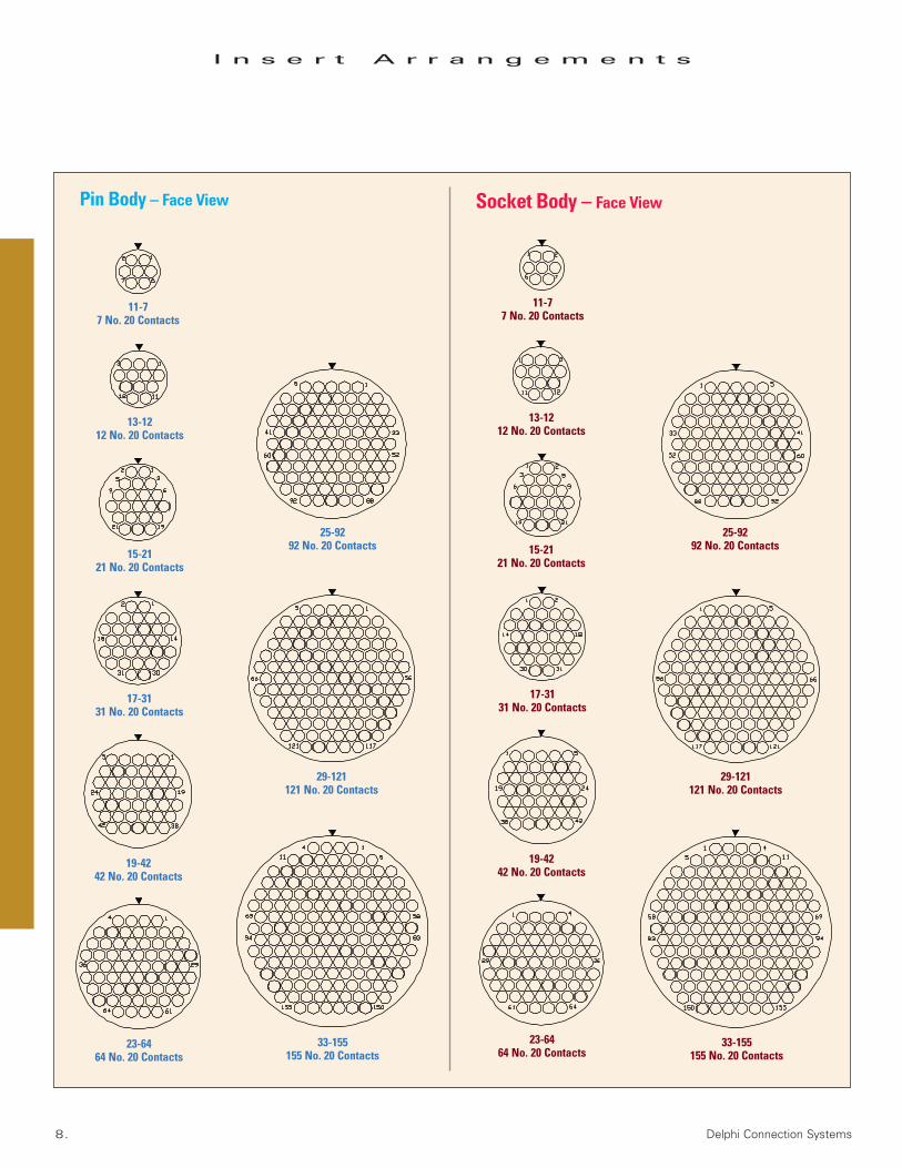
I n s e r t A r r a n g e m e n t s
Pin Body – Face View Socket Body – Face View
11-77 No. 20 Contacts
13-1212 No. 20 Contacts
15-2121 No. 20 Contacts
17-3131 No. 20 Contacts
19-4242 No. 20 Contacts
23-6464 No. 20 Contacts
11-77 No. 20 Contacts
13-1212 No. 20 Contacts
15-2121 No. 20 Contacts
17-3131 No. 20 Contacts
19-4242 No. 20 Contacts
23-6464 No. 20 Contacts
25-9292 No. 20 Contacts
29-121121 No. 20 Contacts
33-155155 No. 20 Contacts
25-9292 No. 20 Contacts
29-121121 No. 20 Contacts
33-155155 No. 20 Contacts

M28840 Connectors • www.delphi.com/connect 9.
K e y / K e y w a y
P o l a r i z a t i o n C h a r t
Keyway
Shell Size Arrangement AA° BSC BB° BSC CC° BSC DD° BSC
Number
1 95 141 208 236
2 113 156 182 292
11 and 13 3 90 145 195 252
4 53 156 220 255
5 119 146 176 298
6 51 141 184 242
1 80 142 196 293
2 135 170 200 310
15, 17, 19, 23 3 49 169 200 244
25, 29 and 30 4 66 140 200 257
5 62 145 180 280
6 79 153 197 272
Receptacle(face view shown)
Plug(face view shown)

10. Delphi Connection Systems
R e c e p t a c l e – W a l l M o u n t
S h e l l S t y l e 0
Dimensions shown are for reference only. Unless otherwise specified, dimensions are in inches and [millimeters].
Shell M Dia. (Ref.) N Dia. Q Dia. R S V Thread W ThreadSize Panel Cutout ID Max. ± .007 [± 0.18] Basic ± .020 [± 0.51] Class 2A Class 2A
in. mm in. mm in. mm in. mm in. mm
11 .812 20.62 .750 19.05 .123 3.12 .750 19.05 1.023 25.98 .7500-20-UNEF .750-.1P-.2L-D.S.
13 .937 23.80 .875 22.22 .123 3.12 .843 21.41 1.138 28.91 .8750-20-UNEF .875-.1P-.2L-D.S.
15 1.124 28.55 1.062 26.97 .123 3.12 .968 24.59 1.258 31.95 1.0000-20-UNEF 1.062-.1P-.2L-D.S.
17 1.187 30.15 1.125 28.58 .123 3.12 1.015 25.78 1.383 35.13 1.1250-18-UNEF 1.125-.1P-.2L-D.S.
19 1.374 34.90 1.312 33.32 .123 3.12 1.140 28.96 1.508 38.30 1.2500-18-UNEF 1.312-.1P-.2L-D.S.
23 1.562 39.67 1.500 38.10 .123 3.12 1.281 32.54 1.718 43.64 1.4375-18-UNEF 1.500-.1P-.2L-D.S.
25 1.687 42.85 1.625 41.27 .150 3.81 1.392 35.36 1.818 46.18 1.5625-18-UNEF 1.625-.1P-.2L-D.S.
29 1.937 49.20 1.812 46.02 .150 3.81 1.568 39.82 2.138 54.31 1.8750-16-UN 1.812-.1P-.2L-D.S.
33 2.124 53.95 2.000 50.80 .175 4.45 1.734 44.04 2.328 59.13 2.0625-16-UN 2.000-.1P-.2L-D.S.
M28840/10GT0A

M28840 Connectors • www.delphi.com/connect 11.
R e c e p t a c l e – C a b l e C o n n e c t i n g
S h e l l S t y l e 1
Dimensions shown are for reference only. Unless otherwise specified, dimensions are in inches and [millimeters].
Shell N Dia. PP TT Dia. V Thread W ThreadSize Max. ± .005 [± 0.13] ± .010 [± 0.25] Class 2A Class 2A
in. mm in. mm in. mm
11 .750 19.05 .763 19.38 .953 24.21 .7500-20-UNEF .750-.1P-.2L-D.S.
13 .875 22.22 .888 22.55 1.078 27.38 .8750-20-UNEF .875-.1P-.2L-D.S.
15 1.062 26.97 1.075 27.30 1.265 32.13 1.0000-20-UNEF 1.062-.1P-.2L-D.S.
17 1.125 28.58 1.138 28.91 1.328 33.73 1.1250-18-UNEF 1.125-.1P-.2L-D.S.
19 1.312 33.32 1.325 33.66 1.515 38.48 1.2500-18-UNEF 1.312-.1P-.2L-D.S.
23 1.500 38.10 1.513 38.43 1.703 43.26 1.4375-18-UNEF 1.500-.1P-.2L-D.S.
25 1.625 41.27 1.638 41.61 1.828 46.43 1.5625-18-UNEF 1.625-.1P-.2L-D.S.
29 1.812 46.02 1.888 47.96 2.078 52.78 1.8750-16-UN 1.812-.1P-.2L-D.S.
33 2.000 50.80 2.075 52.71 2.265 57.53 2.0625-16-UN 2.000-.1P-.2L-D.S.
M28840/11GT1A

12. Delphi Connection Systems
R e c e p t a c l e – B o x M o u n t i n g
S h e l l S t y l e s 2 & 2 2
Shell G Dia. M Dia. (Ref.)* N Dia. Q Dia. R S W ThreadSize ± .007 [± 0.18] Panel Cutout ID Max. ± .007 [± 0.18] Basic ± .020 [± 0.51] Class 2A
in. mm in. mm in. mm in. mm in. mm in. mm
11 .574 14.58 .812 20.62 .750 19.05 .123 3.12 .750 19.05 1.023 25.98 .750-.1P-.2L-D.S.
13 .696 17.68 .937 23.80 .875 22.22 .123 3.12 .843 21.41 1.138 28.91 .875-.1P-.2L-D.S.
15 .874 22.20 1.124 28.55 1.062 26.97 .123 3.12 .968 24.59 1.258 31.95 1.062-.1P-.2L-D.S.
17 .951 24.16 1.187 30.15 1.125 28.58 .123 3.12 1.015 25.78 1.383 35.13 1.125-.1P-.2L-D.S.
19 1.095 27.81 1.374 34.90 1.312 33.32 .123 3.12 1.140 28.96 1.508 38.30 1.312-.1P-.2L-D.S.
23 1.280 32.51 1.562 39.67 1.500 38.10 .123 3.12 1.281 32.54 1.718 43.64 1.500-.1P-.2L-D.S.
25 1.469 37.31 1.687 42.85 1.625 41.27 .150 3.81 1.392 35.36 1.818 46.18 1.625-.1P-.2L-D.S.
29 1.619 41.12 1.874 47.60 1.812 46.02 .150 3.81 1.568 39.82 2.138 54.31 1.812-.1P-.2L-D.S.
33 1.817 46.15 2.062 52.37 2.000 50.80 .175 4.45 1.734 44.04 2.328 59.13 2.000-.1P-.2L-D.S.
M28840/12GT2A
Figure 2Style 22
Figure 1Style 2
* Also refer to Wall Mount/Box Mount illustration and table on page 21. Dimensions shown are for reference only. Unless otherwise specified, dimensions are in inches and [millimeters].

M28840 Connectors • www.delphi.com/connect 13.
R e c e p t a c l e – J a m N u t M o u n t i n g
S h e l l S t y l e 4
M28840/14GT4A
* Also refer to Jam Nut illustration and table on page 21. Dimensions shown are for reference only. Unless otherwise specified, dimensions are in inches and [millimeters].
H Typ. L M Dia.* N*±.005 [±.13]
Shell ± .010 +.004 -.005 Panel Panel RR Dia. SS T Dia. U Thread V Thread W ThreadSize [± 0.25] [+0.10 -0.13] Cutout ID Cutout Flat ±.005 [±0.13] ± .010 [±0.25] ± .010 [±0.25] Class 2A Class 2A Class 2A
in. mm in. mm in. mm in. mm in. mm in. mm in. mm
11 1.062 26.97 .837 21.26 .885 22.48 .848 21.54 .974 24.74 1.264 32.10 1.358 34.49 .8750-20 UNEF .7500-20 UNEF .750-.1P-.2L-D.S.
13 1.188 30.18 .962 24.43 1.010 25.65 .973 24.71 1.099 27.91 1.389 35.28 1.498 38.05 1.0000-20 UNEF .8750-20 UNEF .875-.1P-.2L-D.S.
15 1.375 34.93 1.149 29.18 1.198 30.43 1.160 29.46 1.287 32.69 1.577 40.05 1.671 42.44 1.1875-18 UNEF 1.0000-20 UNEF 1.062-.1P-.2L-D.S.
17 1.438 36.53 1.212 30.78 1.260 32.00 1.223 31.06 1.349 34.26 1.639 41.63 1.733 44.02 1.2500-18 UNEF 1.1250-18 UNEF 1.125-.1P-.2L-D.S.
19 1.625 41.27 1.399 35.53 1.448 36.78 1.410 35.81 1.537 39.04 1.827 46.41 1.921 48.79 1.4375-18 UNEF 1.2500-18 UNEF 1.312-.1P-.2L-D.S.
23 1.812 46.02 1.587 40.31 1.635 41.53 1.598 40.59 1.724 43.79 2.014 51.15 2.108 53.54 1.6250-18 UNEF 1.4375-18 UNEF 1.500-.1P-.2L-D.S.
25 2.000 50.80 1.712 43.48 1.760 44.70 1.723 43.76 1.849 46.96 2.139 54.33 2.233 56.72 1.7500-18 UNS 1.5625-18 UNEF 1.625-.1P-.2L-D.S.
29 2.188 55.57 1.899 48.23 1.948 49.48 1.910 48.51 2.037 51.74 2.327 59.10 2.425 61.60 1.9375-16 UN 1.8750-16 UN 1.812-.1P-.2L-D.S.
33 2.375 60.32 2.087 53.01 2.135 54.23 2.098 53.29 2.224 56.49 2.514 63.85 2.608 66.24 2.1250-16 UN 2.0625-16 UN 2.000-.1P-.2L-D.S.
14. Delphi Connection Systems
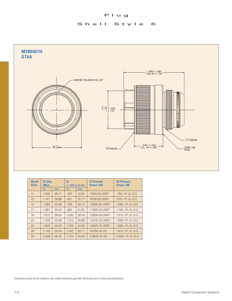
Shell D Dia. E V Thread W ThreadSize Max. ± .005 [± 0.13] Class 2A Class 2B
in. mm in. mm
11 1.028 26.11 .497 12.62 .7500-20 UNEF .750-.1P-.2L-D.S.
13 1.141 28.98 .621 15.77 .8750-20 UNEF .875-.1P-.2L-D.S.
15 1.263 32.08 .793 20.14 1.0000-20 UNEF 1.062-.1P-.2L-D.S.
17 1.387 35.23 .863 21.92 1.1250-18 UNEF 1.125-.1P-.2L-D.S.
19 1.513 38.43 1.030 26.16 1.2500-18 UNEF 1.312-.1P-.2L-D.S.
23 1.703 43.26 1.215 30.86 1.4375-18 UNEF 1.500-.1P-.2L-D.S.
25 1.825 46.35 1.376 34.95 1.5625-18 UNEF 1.625-.1P-.2L-D.S.
29 2.143 54.43 1.542 39.17 1.8750-16 UN 1.812-.1P-.2L-D.S.
33 2.329 59.16 1.734 44.04 2.0625-16 UN 2.000-.1P-.2L-D.S.
P l u g
S h e l l S t y l e 6
Dimensions shown are for reference only. Unless otherwise specified, dimensions are in inches and [millimeters].
M28840/16GT6A
M28840 Connectors • www.delphi.com/connect 15.
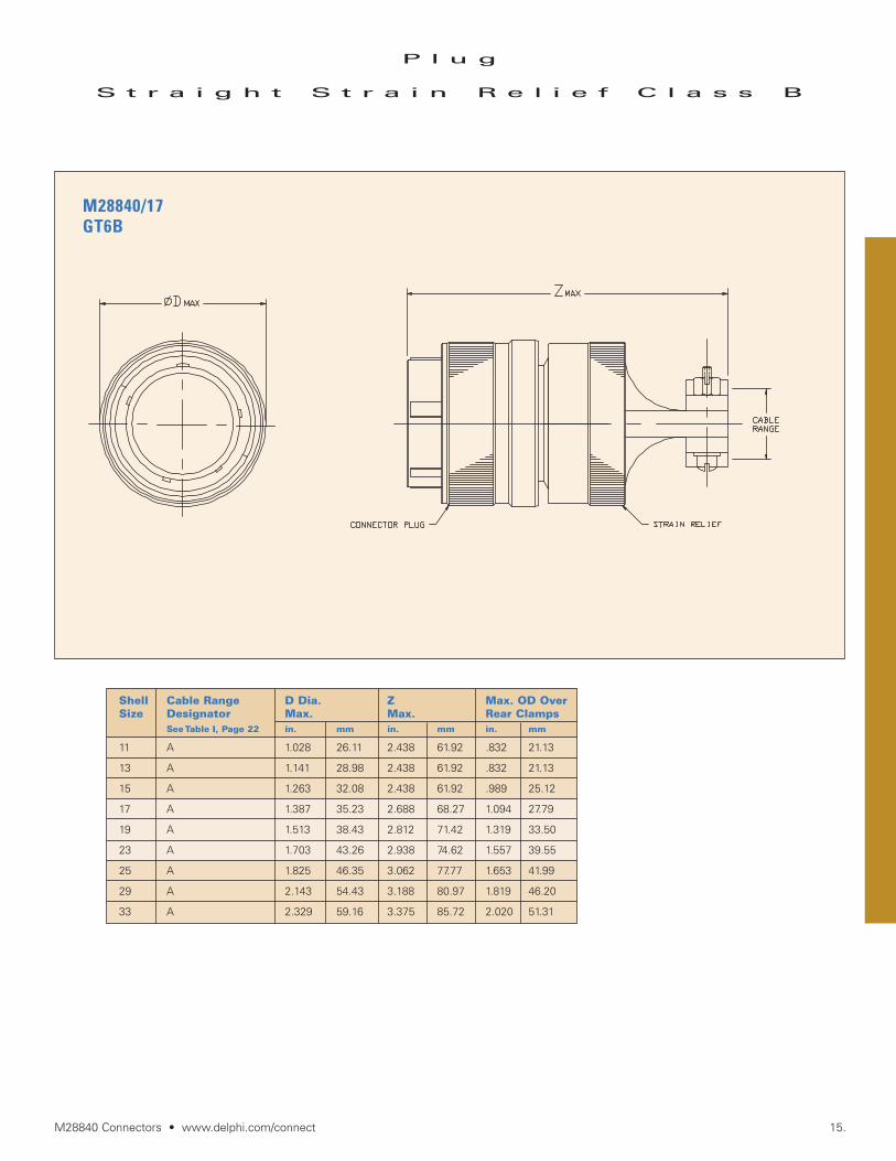
Shell Cable Range D Dia. Z Max. OD OverSize Designator Max. Max. Rear Clamps
See Table I, Page 22 in. mm in. mm in. mm
11 A 1.028 26.11 2.438 61.92 .832 21.13
13 A 1.141 28.98 2.438 61.92 .832 21.13
15 A 1.263 32.08 2.438 61.92 .989 25.12
17 A 1.387 35.23 2.688 68.27 1.094 27.79
19 A 1.513 38.43 2.812 71.42 1.319 33.50
23 A 1.703 43.26 2.938 74.62 1.557 39.55
25 A 1.825 46.35 3.062 77.77 1.653 41.99
29 A 2.143 54.43 3.188 80.97 1.819 46.20
33 A 2.329 59.16 3.375 85.72 2.020 51.31
P l u g
S t r a i g h t S t r a i n R e l i e f C l a s s B
M28840/17GT6B
16. Delphi Connection Systems
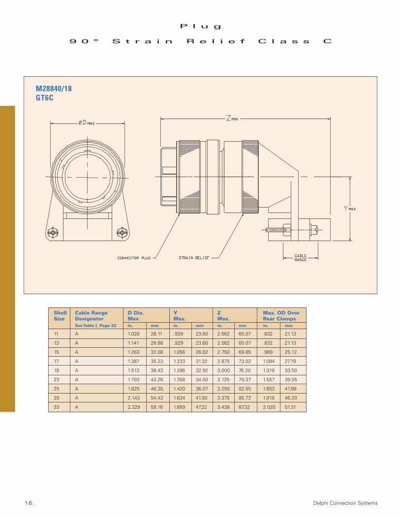
Shell Cable Range D Dia. Y Z Max. OD OverSize Designator Max. Max. Max. Rear Clamps
See Table I, Page 22 in. mm in. mm in. mm in. mm
11 A 1.028 26.11 .929 23.60 2.562 65.07 .832 21.13
13 A 1.141 28.98 .929 23.60 2.562 65.07 .832 21.13
15 A 1.263 32.08 1.056 26.82 2.750 69.85 .989 25.12
17 A 1.387 35.23 1.233 31.32 2.875 73.02 1.094 27.79
19 A 1.513 38.43 1.296 32.92 3.000 76.20 1.319 33.50
23 A 1.703 43.26 1.358 34.50 3.125 79.37 1.557 39.55
25 A 1.825 46.35 1.420 36.07 3.250 82.55 1.653 41.99
29 A 2.143 54.43 1.634 41.50 3.375 85.72 1.819 46.20
33 A 2.329 59.16 1.859 47.22 3.438 87.32 2.020 51.31
P l u g
9 0 ° S t r a i n R e l i e f C l a s s C
M28840/18GT6C
M28840 Connectors • www.delphi.com/connect 17.
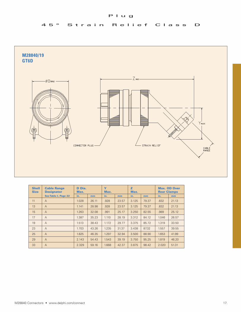
P l u g
4 5 ° S t r a i n R e l i e f C l a s s D
Shell Cable Range D Dia. Y Z Max. OD OverSize Designator Max. Max. Max. Rear Clamps
See Table I, Page 22 in. mm in. mm in. mm in. mm
11 A 1.028 26.11 .928 23.57 3.125 79.37 .832 21.13
13 A 1.141 28.98 .928 23.57 3.125 79.37 .832 21.13
15 A 1.263 32.08 .991 25.17 3.250 82.55 .989 25.12
17 A 1.387 35.23 1.110 28.19 3.312 84.12 1.046 26.57
19 A 1.513 38.43 1.172 29.77 3.375 85.72 1.319 33.50
23 A 1.703 43.26 1.235 31.37 3.438 87.32 1.557 39.55
25 A 1.825 46.35 1.297 32.94 3.500 88.90 1.653 41.99
29 A 2.143 54.43 1.543 39.19 3.750 95.25 1.819 46.20
33 A 2.329 59.16 1.668 42.37 3.875 98.42 2.020 51.31
M28840/19GT6D

18. Delphi Connection Systems
P l u g
S t r a i g h t E n v i r o n m e n t a l
B a c k s h e l l – C l a s s E & F
Shell Cable Range D Dia. F ZSize Designator Max. Max. Max.
See Table II, Page 22 in. mm in. mm in. mm
A 1.156 29.36 .938 23.83 6.500 165.1011 B 1.156 29.36 1.125 28.57 6.500 165.10
C 1.281 32.54 1.312 33.32 6.500 165.10
A 1.156 29.36 1.125 28.57 6.500 165.1013 B 1.281 32.54 1.312 33.32 6.500 165.10
C 1.406 35.71 1.312 33.32 7.000 177.80
A 1.281 32.54 1.125 28.57 6.500 165.1015 B 1.281 32.54 1.312 33.32 6.500 165.10
C 1.406 35.71 1.312 33.32 7.000 177.80D 1.406 35.71 1.593 40.46 7.000 177.80
A 1.406 35.71 1.312 33.32 7.000 177.8017 B 1.406 35.71 1.593 40.46 7.000 177.80
C 1.406 35.71 1.593 40.46 7.000 177.80
19 A 1.531 38.89 1.312 33.32 7.000 177.80B 1.531 38.89 1.750 44.45 7.000 177.80
A 1.656 42.06 1.593 40.46 7.500 190.5023 B 1.656 42.06 1.750 44.45 7.625 193.67
C 1.656 42.06 2.093 53.16 7.812 198.42
A 1.781 45.24 1.750 44.45 7.625 193.6725 B 1.781 45.24 2.093 53.16 8.312 211.12
C 1.781 45.24 2.093 53.16 8.312 211.12D 2.156 54.76 2.343 59.51 8.312 211.12
29 A 2.156 54.76 2.093 53.16 8.312 211.12B 2.156 54.76 2.343 59.51 8.312 211.12
33 A 2.281 57.94 2.343 59.51 8.312 211.12B 2.281 57.94 2.750 69.85 8.625 219.07
Class E = Straight Environmental Backshell
Class F = Straight Environmental / EMI Backshell
M28840/26GT6EGT6F
M28840 Connectors • www.delphi.com/connect 19.
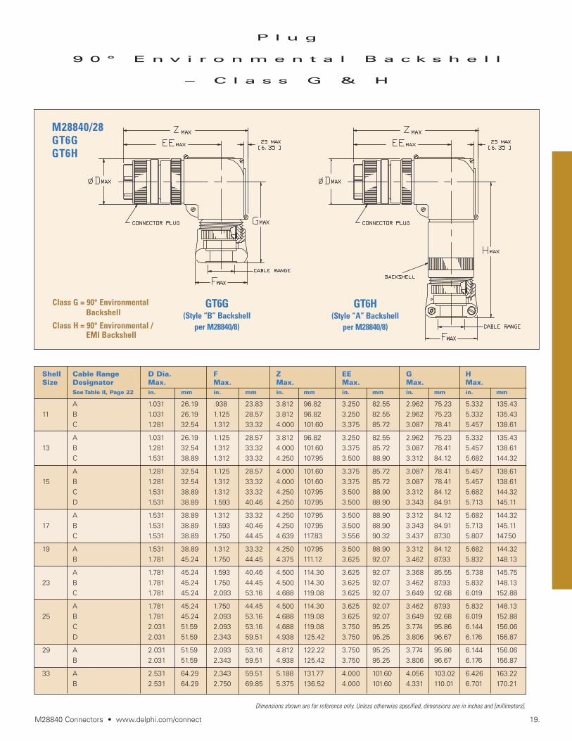
Shell Cable Range D Dia. F Z EE G HSize Designator Max. Max. Max. Max. Max. Max.
See Table II, Page 22 in. mm in. mm in. mm in. mm in. mm in. mm
A 1.031 26.19 .938 23.83 3.812 96.82 3.250 82.55 2.962 75.23 5.332 135.4311 B 1.031 26.19 1.125 28.57 3.812 96.82 3.250 82.55 2.962 75.23 5.332 135.43
C 1.281 32.54 1.312 33.32 4.000 101.60 3.375 85.72 3.087 78.41 5.457 138.61
A 1.031 26.19 1.125 28.57 3.812 96.82 3.250 82.55 2.962 75.23 5.332 135.4313 B 1.281 32.54 1.312 33.32 4.000 101.60 3.375 85.72 3.087 78.41 5.457 138.61
C 1.531 38.89 1.312 33.32 4.250 107.95 3.500 88.90 3.312 84.12 5.682 144.32
A 1.281 32.54 1.125 28.57 4.000 101.60 3.375 85.72 3.087 78.41 5.457 138.6115 B 1.281 32.54 1.312 33.32 4.000 101.60 3.375 85.72 3.087 78.41 5.457 138.61
C 1.531 38.89 1.312 33.32 4.250 107.95 3.500 88.90 3.312 84.12 5.682 144.32D 1.531 38.89 1.593 40.46 4.250 107.95 3.500 88.90 3.343 84.91 5.713 145.11
A 1.531 38.89 1.312 33.32 4.250 107.95 3.500 88.90 3.312 84.12 5.682 144.3217 B 1.531 38.89 1.593 40.46 4.250 107.95 3.500 88.90 3.343 84.91 5.713 145.11
C 1.531 38.89 1.750 44.45 4.639 117.83 3.556 90.32 3.437 87.30 5.807 147.50
19 A 1.531 38.89 1.312 33.32 4.250 107.95 3.500 88.90 3.312 84.12 5.682 144.32B 1.781 45.24 1.750 44.45 4.375 111.12 3.625 92.07 3.462 87.93 5.832 148.13
A 1.781 45.24 1.593 40.46 4.500 114.30 3.625 92.07 3.368 85.55 5.738 145.7523 B 1.781 45.24 1.750 44.45 4.500 114.30 3.625 92.07 3.462 87.93 5.832 148.13
C 1.781 45.24 2.093 53.16 4.688 119.08 3.625 92.07 3.649 92.68 6.019 152.88
A 1.781 45.24 1.750 44.45 4.500 114.30 3.625 92.07 3.462 87.93 5.832 148.1325 B 1.781 45.24 2.093 53.16 4.688 119.08 3.625 92.07 3.649 92.68 6.019 152.88
C 2.031 51.59 2.093 53.16 4.688 119.08 3.750 95.25 3.774 95.86 6.144 156.06D 2.031 51.59 2.343 59.51 4.938 125.42 3.750 95.25 3.806 96.67 6.176 156.87
29 A 2.031 51.59 2.093 53.16 4.812 122.22 3.750 95.25 3.774 95.86 6.144 156.06B 2.031 51.59 2.343 59.51 4.938 125.42 3.750 95.25 3.806 96.67 6.176 156.87
33 A 2.531 64.29 2.343 59.51 5.188 131.77 4.000 101.60 4.056 103.02 6.426 163.22B 2.531 64.29 2.750 69.85 5.375 136.52 4.000 101.60 4.331 110.01 6.701 170.21
P l u g
9 0 ° E n v i r o n m e n t a l B a c k s h e l l
– C l a s s G & H
GT6G(Style “B” Backshell
per M28840/8)
GT6H(Style “A” Backshell
per M28840/8)
Dimensions shown are for reference only. Unless otherwise specified, dimensions are in inches and [millimeters].
Class G = 90° EnvironmentalBackshell
Class H = 90° Environmental /EMI Backshell
M28840/28GT6GGT6H

20. Delphi Connection Systems
Shell Cable Range D Dia. F J EE H K GSize Designator Max. Max. Max. Max. Max. Max. Max.
See Table II, Page 22 in. mm in. mm in. mm in. mm in. mm in. mm in. mm
A 1.031 26.19 .938 23.83 7.404 188.06 3.250 82.55 5.432 137.97 5.728 145.49 3.062 77.7711 B 1.031 26.19 1.125 28.57 7.457 189.41 3.250 82.55 5.432 137.97 5.781 146.84 3.062 77.77
C 1.281 32.54 1.312 33.32 7.727 196.27 3.375 85.72 5.557 141.15 6.051 153.70 3.187 80.95
A 1.031 26.19 1.125 28.57 7.457 189.41 3.250 82.55 5.432 137.97 5.781 146.84 3.062 77.7713 B 1.281 32.54 1.312 33.32 7.727 196.27 3.375 85.72 5.557 141.15 6.051 153.70 3.187 80.95
C 1.531 38.89 1.312 33.32 7.938 201.63 3.500 88.90 5.682 144.32 6.262 159.05 3.312 84.12
A 1.281 32.54 1.125 28.57 7.671 194.84 3.375 85.72 5.557 141.15 5.895 149.73 3.187 80.9515 B 1.281 32.54 1.312 33.32 7.727 196.27 3.375 85.72 5.557 141.15 6.051 153.70 3.187 80.95
C 1.531 38.89 1.312 33.32 7.938 201.63 3.500 88.90 5.682 144.32 6.262 159.05 3.312 84.12D 1.531 38.89 1.593 40.46 8.058 204.67 3.500 88.90 5.713 145.11 6.382 162.10 3.343 84.91
A 1.531 38.89 1.312 33.32 7.938 201.63 3.500 88.90 5.682 144.32 6.262 159.05 3.312 84.1217 B 1.531 38.89 1.593 40.46 8.058 204.67 3.500 88.90 5.713 145.11 6.382 162.10 3.343 84.91
C 1.531 38.89 1.750 44.45 8.161 207.29 3.556 90.32 5.807 147.50 6.485 164.72 3.437 87.30
19 A 1.531 38.89 1.312 33.32 7.938 201.63 3.500 88.90 5.682 144.32 6.282 159.56 3.312 84.12B 1.781 45.24 1.750 44.45 8.371 212.62 3.625 92.07 5.932 150.67 6.695 170.05 3.562 90.47
A 1.781 45.24 1.593 40.46 8.272 210.11 3.625 92.07 5.838 148.28 6.596 167.54 3.468 88.0923 B 1.781 45.24 1.750 44.45 8.371 212.62 3.625 92.07 5.932 150.67 6.695 170.05 3.562 90.47
C 1.781 45.24 2.093 53.16 8.628 219.15 3.625 92.07 6.119 155.42 6.952 176.58 3.749 95.22
A 1.781 45.24 1.750 44.45 8.371 212.62 3.625 92.07 5.932 150.67 6.695 170.05 3.562 90.4725 B 1.781 45.24 2.093 53.16 8.628 219.15 3.625 92.07 6.119 155.42 6.952 176.58 3.749 95.22
C 2.031 51.59 2.093 53.16 8.841 224.56 3.750 95.25 6.244 158.60 7.165 181.99 3.874 98.40D 2.031 51.59 2.343 59.51 8.950 227.33 3.750 95.25 6.276 159.41 7.274 184.76 3.906 99.21
29 A 2.031 51.59 2.093 53.16 8.841 224.56 3.750 95.25 6.244 158.60 7.165 181.99 3.874 98.40B 2.031 51.59 2.343 59.51 8.950 227.33 3.750 95.25 6.276 159.41 7.274 184.76 3.906 99.21
33 A 2.531 64.29 2.343 59.51 9.377 238.18 4.000 101.60 6.526 165.76 7.701 195.61 4.156 105.56B 2.531 64.29 2.750 69.85 9.659 245.34 4.000 101.60 6.801 172.75 7.983 202.77 4.431 112.55
P l u g
4 5 ° E n v i r o n m e n t a l B a c k s h e l l
– C l a s s J & K
GT6J(Style “B” Backshell
per M28840/9)
GT6K(Style “A” Backshell
per M28840/9)
Class J = 45° Environmental Backshell
Class K = 45° Environmental / EMI Backshell
M28840/29GT6JGT6K

M28840 Connectors • www.delphi.com/connect 21.
Shell M R Q Dia. thruSize ± .020 ± .005 Typ. +.010 -.005
[±0.50] [± 0.13] [+0.25 -0.13]
in. mm in. mm in. mm
11 .812 20.62 .750 19.05 .120 3.05
13 .937 23.80 .843 21.41 .120 3.05
15 1.124 28.55 .968 24.59 .120 3.05
17 1.187 30.15 1.015 25.78 .120 3.05
19 1.374 34.90 1.140 28.96 .120 3.05
23 1.562 39.67 1.281 32.54 .120 3.05
25 1.687 42.85 1.392 35.36 .147 3.73
29 1.874 47.60 1.568 39.83 .147 3.73
33 2.062 52.37 1.734 44.04 .173 4.39
R e c e p t a c l e
W a l l M o u n t / B o x M o u n t
P a n e l C u t o u t D i m e n s i o n s
R e c e p t a c l e – J a m N u t
P a n e l C u t o u t D i m e n s i o n s
Shell M NSize ± .005 [± 0.13] ± .005 [± 0.13]
in. mm in. mm
11 .885 22.48 .848 21.54
13 1.010 25.65 .973 24.71
15 1.198 30.43 1.160 29.46
17 1.260 32.00 1.223 31.06
19 1.448 36.78 1.410 35.81
23 1.635 41.53 1.598 40.59
25 1.760 44.70 1.723 43.76
29 1.948 49.48 1.910 48.51
33 2.135 54.23 2.098 53.29
Dimensions shown are for reference only. Unless otherwise specified, dimensions are in inches and [millimeters].
22. Delphi Connection Systems
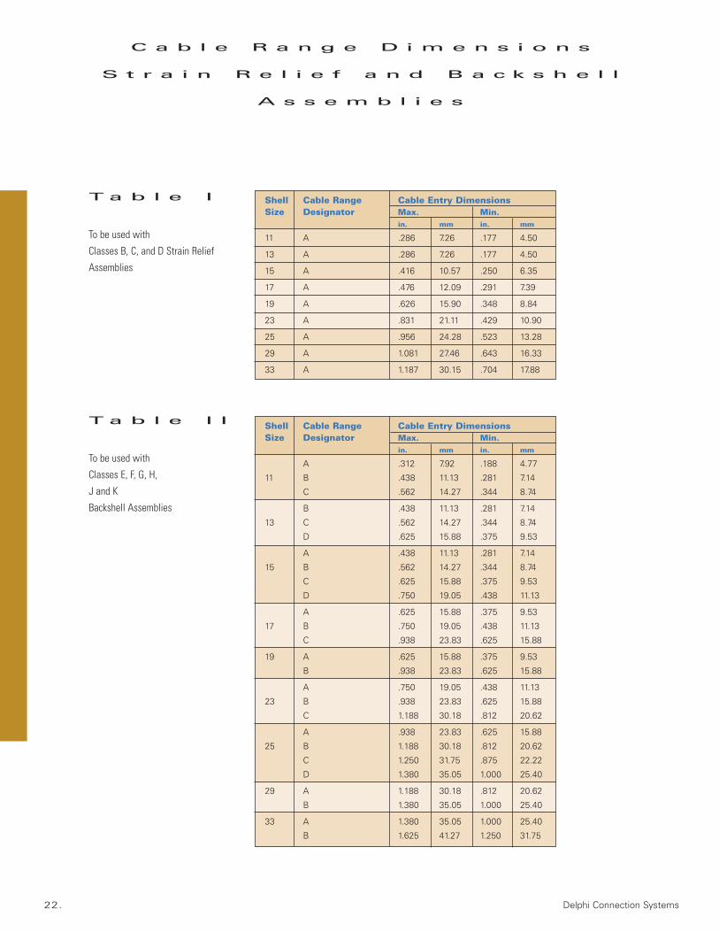
Shell Cable Range Cable Entry DimensionsSize Designator Max. Min.
in. mm in. mm
11 A .286 7.26 .177 4.50
13 A .286 7.26 .177 4.50
15 A .416 10.57 .250 6.35
17 A .476 12.09 .291 7.39
19 A .626 15.90 .348 8.84
23 A .831 21.11 .429 10.90
25 A .956 24.28 .523 13.28
29 A 1.081 27.46 .643 16.33
33 A 1.187 30.15 .704 17.88
C a b l e R a n g e D i m e n s i o n s
S t r a i n R e l i e f a n d B a c k s h e l l
A s s e m b l i e s
Shell Cable Range Cable Entry DimensionsSize Designator Max. Min.
in. mm in. mm
A .312 7.92 .188 4.77
11 B .438 11.13 .281 7.14
C .562 14.27 .344 8.74
B .438 11.13 .281 7.14
13 C .562 14.27 .344 8.74
D .625 15.88 .375 9.53
A .438 11.13 .281 7.14
15 B .562 14.27 .344 8.74
C .625 15.88 .375 9.53
D .750 19.05 .438 11.13
A .625 15.88 .375 9.53
17 B .750 19.05 .438 11.13
C .938 23.83 .625 15.88
19 A .625 15.88 .375 9.53
B .938 23.83 .625 15.88
A .750 19.05 .438 11.13
23 B .938 23.83 .625 15.88
C 1.188 30.18 .812 20.62
A .938 23.83 .625 15.88
25 B 1.188 30.18 .812 20.62
C 1.250 31.75 .875 22.22
D 1.380 35.05 1.000 25.40
29 A 1.188 30.18 .812 20.62
B 1.380 35.05 1.000 25.40
33 A 1.380 35.05 1.000 25.40
B 1.625 41.27 1.250 31.75
T a b l e I
To be used with
Classes B, C, and D Strain Relief
Assemblies
T a b l e I I
To be used with
Classes E, F, G, H,
J and K
Backshell Assemblies
M28840 Connectors • www.delphi.com/connect 23.
D i s t r i b u t i o n S u p p o r t
Koehlke Components, Inc.1201 Commerce Center Blvd. Franklin, Ohio 45005U.S.A.Tel: [1] 937.435.5435Fax: [1] 937.435.1894
www.koehlke.com
Astrex, Inc.205 Express StreetPlainview, New York 11803U.S.A.Tel: [1] 516.433.1700Fax: [1] 516.433.1796
www.astrex.net
Electrical ConnectorsAccessories
Arrow/Zeus Electronics7459 South Lima StreetEnglewood, Colorado 80112U.S.A.Tel: [1] 800.777.2776Fax: [1] 303.824.7772
www.arrow.com
Electrical ConnectorsAccessories
Electrical ConnectorsAccessoriesTools
F a c t o r y S u p p o r t
With a company history that includes Hughes Connecting Devices Division and more
recently Packard-Hughes Interconnect, Delphi Connection Systems offers more than 40
years of technology and expertise in the military and commercial connector markets.
Delphi Connection Systems provides complete interconnect assembly solutions tested
in accordance with applicable performance criteria. For additional product information or
application support, please contact your local Delphi Connection Systems’ sales
representative or contact us directly at [1] 949.660.5701 or visit our website at
www.delphi.com/connect.

Delphi Connection Systems reserves the right to improve, enhance and modify the design specifications and construction of
Delphi products without prior notification. For additional product and engineering information, contact us at [1] 248.813.2334
or visit our website at www.delphi.com/connect.
w w w . d e l p h i . c o m / c o n n e c t
Printed on Recycled Paper ©2004 Delphi. All rights reserved. DP-04-E-114 1104/1M-CirEpi
About Delphi. Multi-national Delphi conducts its business operations through various subsidiaries and has headquarters in Troy, Michigan, USA, Paris, Tokyo and São Paulo, Brazil.
Military Products17150 Von Karman Avenue
Irvine, California 92614 U.S.A.Tel: [1] 949.660.5701 Fax: [1] 949.660.5825
Commercial and Medical Products19200 Asheville Highway
P.O. Box 519Landrum, South Carolina 29356 U.S.A.
Tel: [1] 864.457.3824 Fax: [1] 864.457.2535
Automotive and Transportation ProductsMail Code 483.400.301
5725 Delphi DriveTroy, Michigan 48098-2815 U.S.A.
Tel: [1] 248.813.2334Fax: [1] 248.813.2333
Asia Pacific Regional Headquarters31F Nomura-Buiru
1-26-2 Nishi-Shinjuku, ShinjukuTokyo, Japan 163-0569Tel: [81] 3.5381.1700 Fax: [81] 3.5381.1824
European Regional HeadquartersCustomer Technology Center
Vorm Eichholz 142119 Wuppertal
GermanyTel: [49] 202.291.0
Fax: [49] 202.291.2777
South American Regional HeadquartersAv. Goiás, 1860
São Caetano do SulSão Paulo 09550-050
BrazilTel: [55] 11.4234.9491Fax: [55] 11.4234.9462