mig welding of dissimilar metal (steel and aluminium) … filemig welding of dissimilar metal (steel...
TRANSCRIPT

MIG WELDING OF DISSIMILAR METAL (STEEL AND ALUMINIUM)
MOHD AZIZUL HAFIZ BIN ABDUL SANI
Report submitted in partial fulfillment of the requirements
for the award of Bachelor of Mechanical Engineering with Manufacturing Engineering
Faculty of Mechanical Engineering
UNIVERSITI MALAYSIA PAHANG
JUNE 2012

vii
ABSTRACT
Tailor welded blanks (YWBs) is a method used in automotive industries that offer
an excellent opportunity to reduce manufacturing costs, decrease vehicle weight and
improve the quality of sheet metal stamping. In this project, the objective is to study
welding parameters used in joining two dissimilar metals. Mild steel and aluminium with
thickness both 3mm was weld together using MIG welding with tailor welded blanks
method. Voltages used in this project are 15.5, 17.5 and 20.5 V with feed speed of 65, 90,
and 115 mm/min. The joints were evaluated by mechanical testing and metallurgical
analysis. Microstructural analyses were done using metallography, microhardness testing
and optical microscope. Result of these analysis suggested that failure were seen at the
weld area of the joint. Further, at the fusion zone were form intermetallic compound layer
that soft, brittle and low in mechanical strength.

viii
ABSTRAK
Tailor welded blanks (TWBs) adalah satu kaedah yang digunakan dalam industri
automotif yang menawarkan satu peluang yang baik untuk mengurangkan kos pembuatan,
penurunan berat kenderaan dan meningkatkan kualiti penggunaan bahan logam. Objektif
projek ini adalah untuk mengkaji parameter kimpalan yang digunakan dalam
menggabungkan dua logam yang berbeza. Mild steel dan aluminium dengan kedua-dua
ketebalan 3mm di kimpal bersama-sama menggunakan kimpalan MIG dengan
menggunakan kaedah Tailor welded blanks (TWBs). Voltan yang digunakan dalam projek
ini adalah 15.5 V, 17.5 V dan 20.5 V dengan kelajuan suapan sebanyak 65 mm/min, 90
mm/min, dan 115 mm / min. Bahagian kawasan kimpalan telah dinilai menggunakan ujian
mekanikal dan analisis logam. Analisis mikrostruktur telah dilakukan dengan menggunakan
metalografi, ujian Mikrokekerasan dan mikroskop optik. Keputusan analisis ini
mencadangkan bahawa kegagalan telah kelihatan di bahagian kawasan kimpalan.
Seterusnya, di zon percantuman terbentuk satu lapisan sebatian intermatelik yang lembut,
rapuh dan rendah dalam kekuatan mekanikal.

ix
TABLE OF CONTENT
Page
EXAMINER APPROVAL DOCUMENT
CHAPTER 1 INTRODUCTION
1.1 Introduction 1
1.2 Problem Statement 2
1.3 Project Objective 3
1.4 Scope of Project 3
CHAPTER 2 LITERATURE REVIEW
2.1 Introduction 4
2.2 Welding 4
2.2.1 Type of Welding 5
2.3 MIG Welding 6
2.3.1 Weld Area 7
SUPERVISOR’S DECLARATION iii
STUDENT’S DECLARATION iv
ACKNOWLEDGEMENTS vi
ABSTRACT vii
ABSTRAK viii
TABLE OF CONTENTS ix
LIST OF TABLES xii
LIST OF FIGURES xiii
LIST OF SYMBOLS xv
LIST OF ABBREVIATIONS xvi
x
2.3.2 Tailor Welded Blanks (TWBs) 8
2.4 Material and Weldability 9
2.4.1 Aluminium 10
2.4.2 Mild Steel 12
2.5 Weld Joint 12
2.6 Welding Parameters 14
2.6.1 Voltage 14
2.6.2 Feed Speed 15
2.6.2.1 Type of Feedeer 15
CHAPTER 3 METHODOLOGY
3.1 Introduction 16
3.2 Overview of Methodology 16
3.3 Material Specification 17
3.4 Sample Preparation 18
3.4.1 Shearing Process 18
3.5 Fabrication using MIG Welding 19
3.6 Microstructure Analysis 20
3.6.1 Hot Mounting Process 21
3.6.2 Grinding Process 22
3.6.3 Polishing Process 22
3.6.4 Etching Process 24
3.6.5 Microstructure Observations 25
3.7 Mechanical Property Analysis 26
3.7.1 Tensile Test 26
3.7.2 Vickers Hardness Test 27
3.8 Flow Chart 29
xi
CHAPTER 4 RESULTS & DISCUSSION
4.1 Introduction 31
4.2 Welding Appearance 31
4.3 Microstructure Analysis 33
4.3.1 Base Metal and heat Affected Zone (HAZ) 34
4.3.2 Weld Metal and Fusion Zone 36
4.4 Vickers Hardness Analysis 38
4.5 Tensile Strength Analysis 41
4.6 Welding Defects 44
CHAPTER 5 CONCLUSIONS & RECOMMENDATION
5.1 Conclusion 46
5.2 Recommendation 47
REFERENCES 48
APPENDICES

xii
LIST OF TABLES
Table No. Page
3.1
3.2
3.3
3.4
3.5
3.6
Aluminum alloy AA1100 composition
Mild steel composition
Size of specimens
Fixed welding parameter
Varied welding parameters
Fixed parameters of mounting machine
17
17
18
20
20
22

xiii
LIST OF FIGURES
Figure No. Page
2.1
2.2
2.3
2.4
2.5
3.1
3.2
3.3
3.4
3.5
3.6
3.7
3.8
3.9
3.10
3.11
3.12
4.1
4.2
4.3
4.4
Type of joining (Welding) processes
Schematic of MIG welding
Cross section of a typical fusion welded joint
Exploded view of current and/or potential automotive TWB
applications
Type of Weld joints
Shearing machine
Selco Genesis 352 PSR MIG welding
Simpli Met 1000 Automatic Mounting Press Hot Mounting
machine
HandiMet 2 Roll Grinder
Metken Forcipol 2V grinding/polishing machine
(a) The solution for etching and (b) Fume hood
Leica PME microscope
Metallurgical Microscopic
SHIMADZU AGS-X Series Tensile Test Machine
Geometry of rectangular tensile test specimens (ASTM D1002)
Vickers Hardness machine
Flow chart
The surface and cross section of welding using 15.5V, 17.5V and
20.5V
Region for base metal, heat affected zone (HAZ), filler and fusion
zone
Base metal for mild steel using
Heat affected zone (HAZ) for mild steel
5
6
7
9
12
18
19
21
22
23
24
25
25
26
27
28
29
31
33
34
35

xiv
4.5
4.6
4.7
4.8
4.9
4.10
4.11
4.12
4.13
4.14
4.15
Heat affected zone (HAZ) and base metal for aluminium
Weld metal
Fusion zone where intermetallic compound layer form
Graph of Hardness value vs distance from weld center for 15.5V
Graph of Hardness value vs distance from weld center for 17.5V
Graph of Hardness value vs distance from weld center for 20.5V
Graph of Highest value of hardness for 15.5V, 17.5V and 20.5V
Fracture area of tensile specimens
Graph of Maximum force vs voltage for 15.5V, 17.5V and 20.5V
Defects on welding specimens
Defects on cross section specimens
36
36
37
38
39
39
40
42
43
44
44

xv
LIST OF SYMBOLS
HV Vickers Hardness Number
L length
N Newton
P Load
s Second
V Voltage
xvi
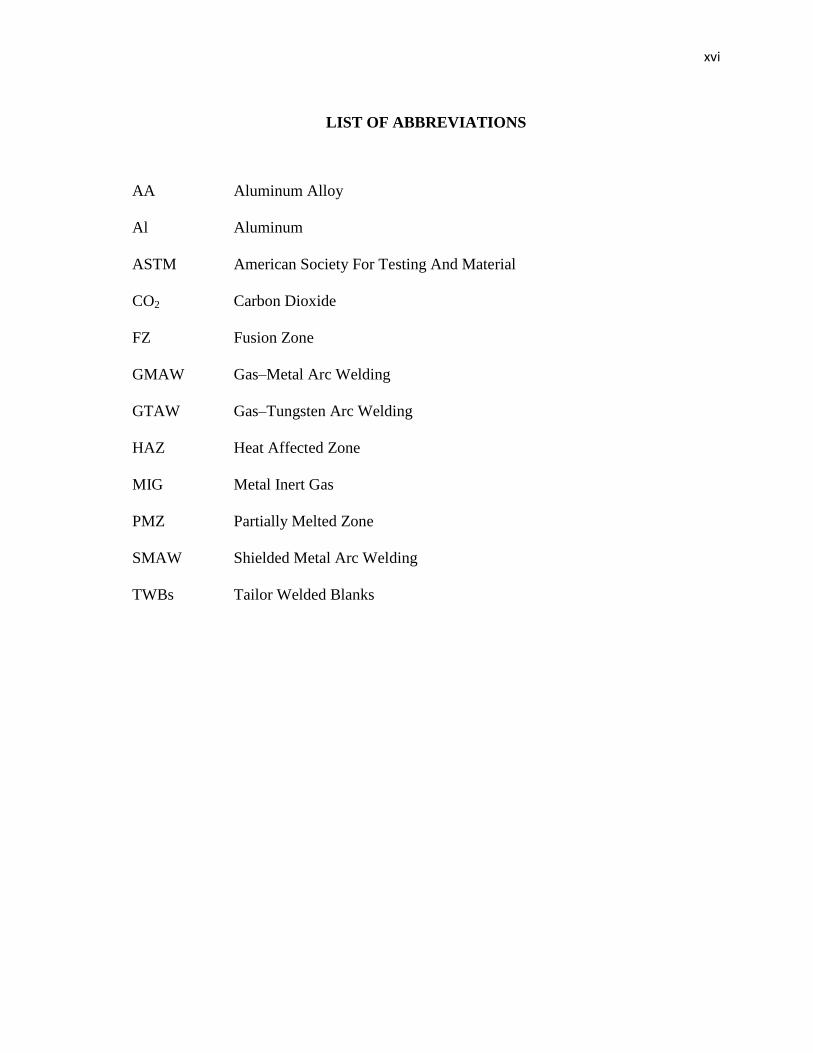
LIST OF ABBREVIATIONS
AA Aluminum Alloy
Al Aluminum
ASTM American Society For Testing And Material
CO2 Carbon Dioxide
FZ Fusion Zone
GMAW Gas–Metal Arc Welding
GTAW Gas–Tungsten Arc Welding
HAZ Heat Affected Zone
MIG Metal Inert Gas
PMZ Partially Melted Zone
SMAW Shielded Metal Arc Welding
TWBs Tailor Welded Blanks

1
CHAPTER 1
INTRODUCTION
1.1 INTRODUCTION
Welding refers to unite or fusing of pieces by using heat or compression. The
source of heat in welding is usually an arc flame produced by the electricity of the
welding power supply. Arc-based welding is called arc welding. Some people call
it soldering but there is a small difference on each. Usually soldering refers to small
joins melting a different material between the parts to weld. The fusing of the pieces can
occur solely based on the heat produced by the arc so that the welding pieces melt
together. This method can be used in MIG welding, for example.
MIG welding is abbreviated for the phrase Metal Inert Gas, and MAG is
abbreviated as Metal Active Gas. Some shielding gases mainly carbon dioxide and
oxygen will react with the welding arc and puddle and help make the weld. So these are
called active gases. But gases like argon and helium do not have any effect on the actual
welding arc and therefore that's why they are called inert gases. It is much faster than
TIG or Stick welding and it can be adapted to robots and used in high end production
facilities where part after part is repetitively manufactured.
Usually a filler metal is, however, melted into the welding seam, or weld, either
using a wire feeder through the welding gun (MIG/MAG welding) or by using a
manual-feed welding rod. In this scenario, the filler metal must have approximately the
same melting point as the material welded. Voltage also one of the welding parameter
that need to be set up correctly according to type of welding and type of materials use.
Incorrect use of voltage may result in defect or inappropriate welding appearance.
2
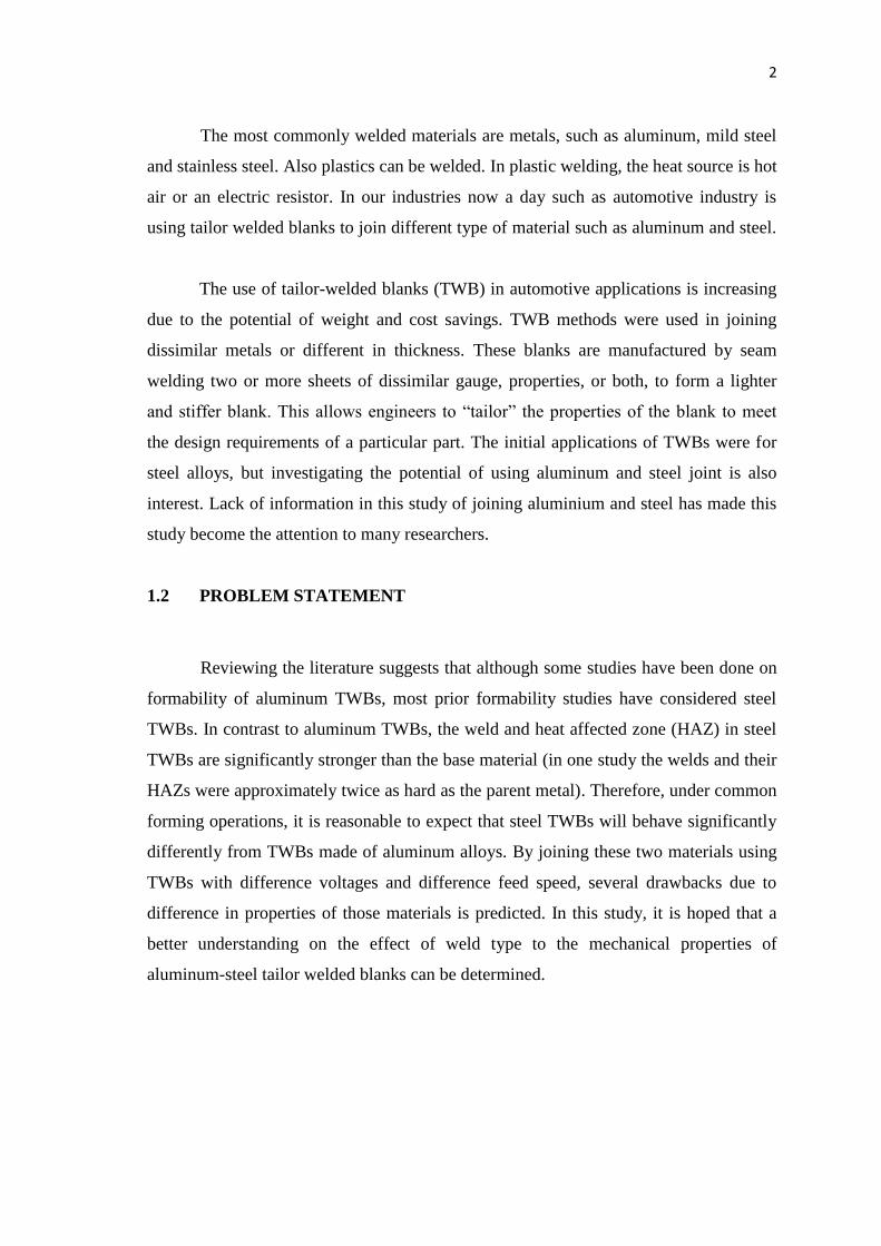
The most commonly welded materials are metals, such as aluminum, mild steel
and stainless steel. Also plastics can be welded. In plastic welding, the heat source is hot
air or an electric resistor. In our industries now a day such as automotive industry is
using tailor welded blanks to join different type of material such as aluminum and steel.
The use of tailor-welded blanks (TWB) in automotive applications is increasing
due to the potential of weight and cost savings. TWB methods were used in joining
dissimilar metals or different in thickness. These blanks are manufactured by seam
welding two or more sheets of dissimilar gauge, properties, or both, to form a lighter
and stiffer blank. This allows engineers to ―tailor‖ the properties of the blank to meet
the design requirements of a particular part. The initial applications of TWBs were for
steel alloys, but investigating the potential of using aluminum and steel joint is also
interest. Lack of information in this study of joining aluminium and steel has made this
study become the attention to many researchers.
1.2 PROBLEM STATEMENT
Reviewing the literature suggests that although some studies have been done on
formability of aluminum TWBs, most prior formability studies have considered steel
TWBs. In contrast to aluminum TWBs, the weld and heat affected zone (HAZ) in steel
TWBs are significantly stronger than the base material (in one study the welds and their
HAZs were approximately twice as hard as the parent metal). Therefore, under common
forming operations, it is reasonable to expect that steel TWBs will behave significantly
differently from TWBs made of aluminum alloys. By joining these two materials using
TWBs with difference voltages and difference feed speed, several drawbacks due to
difference in properties of those materials is predicted. In this study, it is hoped that a
better understanding on the effect of weld type to the mechanical properties of
aluminum-steel tailor welded blanks can be determined.

3
1.3 OBJECTIVES
The objectives of this thesis are to:
i. Investigate the effects joining mild steel - aluminum with various voltage and
feed speed.
ii. Investigate the weld quality and defects using optical devices.
iii. Investigate the specimen’s mechanical property using mechanical testing
machine.
1.4 SCOPES
This project is confined to the following scopes of study:
i. Fabricate aluminum-steel tailor welded blanks using MIG welding with
various voltages and feed speed.
ii. Analyzed the microstructure and phase composition of the joints using
optical microscope.
iii. Analyzed the weld quality and the mechanical property using mechanical
testing machine.

4
CHAPTER 2
LITERATURE REVIEW
2.1 INTRODUCTION
This chapter provides the detail description literature review done according to
the title of ―MIG Welding of Dissimilar Metal‖. The aim of this project is to investigate
the weld joint’s quality and defects of steel and aluminum, as well as the type of groove
and feed speed. This literature review will give an overview and a brief introduction of
the techniques that are suitable to be used to achieve all the objectives.
2.2 WELDING
Welding process is a type of consolidation process to facilitate joining or
assembly. It is a permanent joining of two materials, usually metals, by coalescence. It
is introduced by a combination of temperature, pressure and metallurgical condition.
(Kalpakjian, 2007)

5
2.2.1 TYPE OF WELDING
There are two major categories of welding which is fusion welding and also
solid state welding as shown in Figure 2.1. The definitions of this two major type of
welding are:
• Fusion welding - coalescence is accomplished by melting the two parts to be
joined, in some cases adding filler metal to the joint. Some of the examples are
arc welding, resistance spot welding and oxyfuel gas welding.
• Solid state welding - heat and/or pressure are used to achieve coalescence, but
no melting of the base metals occurs and no filler metal is added. Some
examples are forge welding, diffusion welding and friction welding.
Figure 2.1: Type of joining (Welding) processes
Source: Kalpakjian, 2007
6
2.3 MIG WELDING
MIG welding is a welding process where an electrode wire is continuously fed
from an automatic wire feeder through a conduit and welding gun to the base metal,
where a weld pool is created. There are two type of MIG welding which is semi-
automatic and fully automated. If a welder is controlling the direction of travel and
travel speed the process is considered semi-automatic. The process is fully automated
when machine control direction of travel and travel speed. (Derek Pritchard, 2001)
In this project, we are focusing on using MIG welding as method use in joining
process. It is chosen because:
i. It is compatible with all commercial metals.
ii. Welding can be performed in all positions.
iii. Manipulation skills are easily learnt and mastered by apprentices.
iv. It is still practical for using MIG welding in Malaysia.
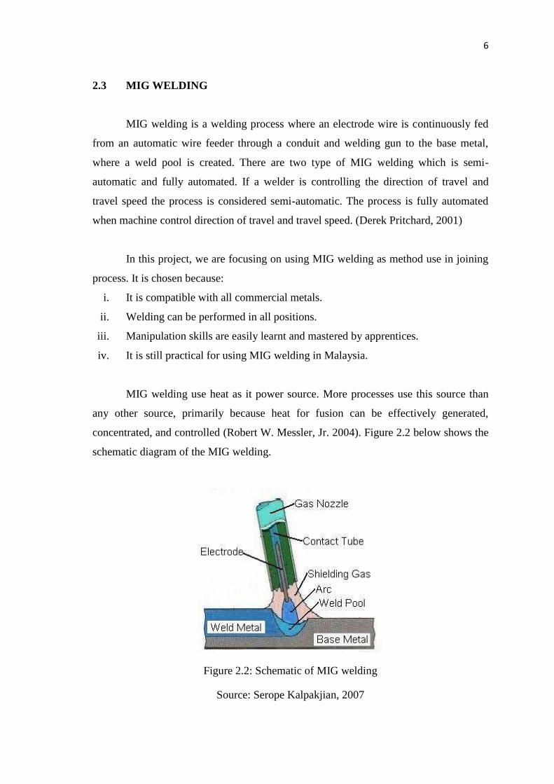
MIG welding use heat as it power source. More processes use this source than
any other source, primarily because heat for fusion can be effectively generated,
concentrated, and controlled (Robert W. Messler, Jr. 2004). Figure 2.2 below shows the
schematic diagram of the MIG welding.
Figure 2.2: Schematic of MIG welding
Source: Serope Kalpakjian, 2007

7
The advantages of MIG welding:
i. All position capability
ii. Higher deposition rates than SMAW
iii. Less operator skill required
iv. Long welds can be made without starts and stops
v. Minimal post weld cleaning is required
2.3.1 WELD AREA
Typical fusion weld joint in which filler metal has been added consists of fusion
zone, weld interface, and heat affected zone and unaffected base metal zone
(Kalpakjian, 2007). These entire zones in weld area are shown in Figure 2.3 below.
Figure 2.3: Cross section of a typical fusion welded joint:
(a) principal zones in the joint, and (b) typical grain structure
Source: Kalpakjian, 2007
Heat affected zone (HAZ) is where the area experienced temperatures below
melting point, but high enough to cause micro structural changes in the solid metal.
Chemical composition still same as base metal, but this region has been heat treated so
that its properties and structure have been altered (Kalpakjian, 2007).
8
2.3.2 TAILOR WELDED BLANKS (TWB)
One of the recent methods used to weld two different type materials
together is tailor welded blanks. By using this process, it is possible to produce a
finished part with varying material properties, leading to component optimization. Mash
seam, high frequency butt, friction, laser welding process and also MIG welding which
is used in the project can also be used for welding tailored blanks (Brad Kinsey, 2001).
The potential of tailor welded blanks was soon recognized by the steel industry
and was addressed in the collaborative Ultra Light Steel Auto Body project, which was
to become known as ULSAB project. Porsche engineering services in conjunction with
35 steel companies worldwide produced a vehicle design which more than half to the
body in white was to be made from tailor welded blanks. Figure 2.4 illustrated how
multi-material blanks were use to fabricate many components that make up the body in
white, ranging from the large floor pan, which is a simple assembly of three trapezoidal
sections, to the more complex five-piece side section utilizing multi-material and pre-
cut holes.( Brad L. Kinsey, 2003)

9
Figure 2.4: Exploded view of current and/or potential automotive TWB applications
Source: Brad L. Kinsey, 2003
Sheet steel is used widely for the manufacture of products in the electrical
goods, packaging and construction markets and a number of these may benefit from the
application of tailored blanks. In fact, any product that requires change in material
properties within sheet steel components could be improved by the use of tailored
blanks (Brad L. Kinsey, 2003).
2.4 MATERIAL AND WELDABILITY
Weldability is a term used to describe the relative ease or difficulty with which a
metal or alloy can be welded. The better the weldability, the easier it is to weld.
However, weldability is a complicated property, as it encompasses the metallurgical
compability of the metal alloy with a specific welding process.

10
2.4.1 ALUMINIUM
Aluminium welding has its own problem due to the properties of aluminium.
Aluminium has high thermal conductivity, high chemical reactivity with oxygen, and
high hydrogen solubility at high temperature. This properties can affect the welded joint
because the present of defects on the weld bead. Aluminium alloys used in aerospace,
automobile industries, railway vehicles, bridges, and high speed ships because it has
light weight, higher strength to weight ratio and good corrosion resistance (A.K.
Lakshminarayanan et al, 2009). There are eight series of alloying element in aluminium
alloy. These eight series of aluminium are:
a) Pure Aluminum (1XXX series) Contains no alloying elements, and is not heat-
treatable. It is used primarily in chemical tanks and pipe because of its superior
corrosion resistance. This series is also used in electrical bus conductors because
of its excellent electrical conductivity. It is welded easily with 1100 and 4043
filler wires.
b) Copper (2XXX series) Provides high strength to aluminum. This series is heat-
treatable and mainly used in aircraft parts, rivets and screw products. Most
2XXX series alloys are considered poor for arc welding because of their
sensitivity to hot cracking. Most of these alloys should not be welded, however,
alloys 2014, 2219 and 2519 are easily welded with 4043 or 2319 filler wire.
These three alloys are widely used in welded fabrication.
c) Manganese (3XXX series) Yields a nonheat-treatable series used for general-
purpose fabrication and build-up. Moderate in strength, the 3XXX series is used
for forming applications including utility and van trailer sheet. It is improved
through strain hardening to provide good ductility and improved corrosion
properties. Typically welded with 4043 or 5356 filler wire, the 3XXX series is
excellent for welding and not prone to hot cracking. Its moderate strengths
prevent this series from being used in structural applications.
d) Silicon (4XXX series) Silicon reduces the melting point of the aluminum and
improves fluidity. Its principle use is as filler metal. The 4XXX series has good

11
weldability and is considered a nonheat-treatable alloy. Alloy 4047 is often used
in the automotive industry as it is very fluid and good for brazing and welding.
e) Magnesium (5XXX series) When added to aluminum, magnesium has excellent
weldability, good structural strength and is not prone to hot cracking. In fact, the
5XXX series has the highest strength of the nonheat-treatable aluminum alloys.
It is used for chemical storage tanks and pressure vessels as well as structural
applications, railway cars, dump trucks and bridges because of its corrosion
resistance.
f) Silicon and Magnesium (6XXX series) This medium strength, heat-treatable
series, is primarily used in automotive, pipe, railings, and structural extrusion
applications. The 6XXX series is prone to hot cracking, but this problem can be
overcome by the correct choice of joint and filler metal. Can be welded with
either 5XXX or 4XXX series without cracking — adequate dilution of the base
alloys with selected filler wire is essential. A 4043 filler wire is the most
common for use with this series. 6XXX alloys should never be welded
autogenously, they will crack.
g) Zinc (7XXX series) Zinc added to aluminum with magnesium and copper
produces the highest strength heat-treatable aluminum alloy. It is primarily used
in the aircraft industry. The weldability of the 7XXX series is compromised in
higher copper grades, as many of these grades are crack sensitive (due to wide
melting ranges and low solidus melting temperatures). Grades 7005 and 7039
are weldable with 5XXX filler wires. They are widely used for bicycle frames
and other extruded applications.
h) Other (8XXX series) Other elements that are alloyed with aluminum (i.e.
lithium) all fall under this series. Most of these alloys are not commonly welded,
though they offer very good rigidity and are principally used in the aerospace
industry. Filler wire selection for these heat-treatable alloys include the 4XXX
series. (Cary and Helzer, 2005)
The aluminium chosen for this project is aluminium AA1100 because this series
of aluminium is commercially pure aluminium that widely use in our industries such as
chemical tank and pipe. Aluminium 1xxx series contains no alloying elements and is

12
not heat treatable. It used primarily because of its superior corrosion resistance. This
series also used in electrical bus conductor because of ots excellent electrical
conductivity. It is welded easily with 1100 and 4043 filler wires (Gene Mathers, 2002).
2.4.2 MILD STEEL
Steels are commonly weldable, but there are many types of steel where special
Welding-steel procedures must be implemented to perform acceptable welds. Welding-
steel concerned with the weldability of various kinds of this material. Low carbon
steels, having less than 0.25% carbon, display good weldability, meaning it can easily
weld by using any arc, gas and resistance welding (Kalpakjian and Schmid, 2006).
2.5 WELD JOINT
The weld joint is where two or more metal parts are joined by welding. The
several basic types of weld joints are the butt, corner, tee, lap, and edge, as shown in
Figure 2.5. (Kalpakjian, 2007).
Figure 2.5: Type of Weld joints
Source: Kalpakjian, 2007

13
Some common types of welding:
1. A butt joint is used to join two members aligned in the same plane (Figure 2.4,
view a). This joint is frequently used in plate, sheet metal, and pipe work. A
joint of this type may be either square or grooved. Some of the variations of this
joint are discussed later in this chapter.
2. Corner and tee joints are used to join two members located at right angles to
each other (Figure 2.4, view and k). In cross section, the corner joint forms an L-
shape, and the tee joint has the shape of the letter T. Various joint designs of
both types have uses in many types of metal structures.
3. A lap joint, as the name implies, is made by lapping one piece of metal over
another (Figure 2.4, view l). This is one of the strongest types of joints available;
however, for maximum joint efficiency, you should overlap the metals a
minimum of three times the thickness of the thinnest member you are joining.
Lap joints are commonly used with torch brazing and spot welding applications.
4. An edge joint is used to join the edges of two or more members lying in the
same plane. In most cases, one of the members is flanged, as shown in Figure
2.4, view m. While this type of joint has some applications in plate work, it is
more frequently used in sheet metal work An edge joint should only be used for
joining metals 1/4 inch or less in thickness that are not subjected to heavy loads.
In this project on joining mild steel and aluminium using MIG welding, lap
joints were used as the type of weld joint. This type of joint is use because of the high
difference in melting temperature of steel and aluminium. Mild steel were put on top of
the aluminium so that aluminium will not directly contact with the heat source. It is to
avoid aluminium from melt to fast.