midwest at-6 - images.rcuniverse.comimages.rcuniverse.com/forum/upfiles/450270/lj23780.pdf · about...
TRANSCRIPT

Success Series lete and fully
ThiS kit featu res a comp t Hlustrated step-bymiddotstep C07S~~Ut~~~n
manual ANDmiddot fullmiddotsIze P a
Midwest
AT-6 reg
ASSURE SUCCESS
Kit 177
A Sport-Scale
Military Trainer
About This Construction Manual
This booklet divides the construction into sub-assemblies wing fuselage etc Read each secshytion carefully and identify all of the parts before starting on a particular sub-assembly There is a complete description of all kit parts under Kit Contents (Pages 3 - 9) Please check to be sure that your kit is complete that is not missing any parts If you do find that parts arc missing or you are having trouble identifying parts see Customer Service (below) The instructions give the sizes of all the parts Refer back to the Kit contents when selecting parts to be sure that you arc using the correct sizes
This manual shows dimensions in inches and metric the metric dimensions being given in pashyrenthesis following the inch figures Example 3 (76mm) Since there is rarely a direct inch to metric conversion in many Cltlses a close approximation is quoted
The illustrations in this manual clarify and detail many of the assemblies shown on the plan and the two should be used together during construction
Customer Service
Should you experience a problem with this kit we recommend you see your deafer first [fyou are unable to solve the problem feel free to call or write
Customer Service Department Midwest Products Co Inc PO Box 564 Hobart IN 46342 (219) 942-1134
This product is sold with exdusion of all warranty expressed or~MIDWEST implied statutory or otherwise Buyer assumes alilisk of use PRODUCTS CO INC
400 S Indiana S1 PO Box 564 Hobart IN 46342
P-426
Table of Contents
I About This Construction Manual Page No Customer service
II Kit Contents Fuselage 3-5 Wing 5-7 Control surfaces 7-8 Fixed gear 9 Miscellaneous 9 Additional items you will need to build an operable RC model 9
III Getting Started Tools and materials you will need 10
IV Assembly Instructions Control surfaces 11-17 Wing construction 17-29 Fuselage 30-45 Fixed landing gear 46 Retractable landing gear 47 Mltunting thewing 48-50 JOining the wings 50-51
V Finishing 51-52
VI Final Assembly 53-57
VII Flying Your MidwestAT-6 57-58
VIII Acknowledgements 58
IX Product Evaluation CardCatalog Offer 63
2
PT 33127 - 1 REQUIRED
lS X2-7S x 16-7S
(32mm x 73mm x 429mm)
BALSA LEFT PUSH ROD SUPPORT
Kit Contents
Note All wood parts are balsa unless noted
Fuselage
Part no Qty Dimensions Metric (mm) Description
33162 2 332 x 1W x 4-78 23 x 64 x 124 Filler strip 33161 2 18 x 2-12 x 23-7f 32 x 635 x 006 Forward top sheet
I 331$7 2 18 x 2-112 x 26-7f 32 x 635 x 683 Rear top sheet 33155 2 18 x 3-78 x 26-78 32 x 984 x 683 Rear 2 sheet 33156 2 18 x 2-14 x 18-78 32 x 572 x 479 Rear 3 sheet 33181 4 34 x 34 x 34 19x19x19 Spruce cowl blocks 33158 2 18 x 2-78 x 23-7f 32x 73 x 006 Forward 2 sheet 33159 1 112 x 2-78 x 2-78 127x73x73 Stabilizer filler 33163 2 1W x 14 x 23-78 64 x 64 x 606 Lower side stringer 33164 2 14 x 14 x 15-78 64 x 64 x 403 Bottom stringer 33178 4 14x1x3-12 64 x 254 x 89 Plywood firewall sides 33166 1 38 x 1-1 (2 x 4-78 95x38x 124 Cockpit rear block 33177 1 14 x 3-3W x 3-34 64 x 952 x 952 Plywood firewall 33165 1 112ft x 1-78 x 2-112 12 7 x 476 x 635 Tall filler 33156 2 18 x 2-78 x 23-78 32 x 73 x 006 Forward 1t3 sheet 33179 8 14 x 1-14 x 1-1(2 64 x 318 x 38 Plywood fuselage bolt plate 33180 2 14 x 58 x 6-78 64 x 159x 175 Plywood servo ralls 33175 1 1-14 x 1-12 x 4-716 318 x 38 x 113 Air scoop 33167 2 18 x 78 x 11-78 32 x 222 x 302 Top sheet 33156 2 18 x 2-788 x 23-7S 32 x 73xOO6 Aft bottom sheet 33172 2 1-18 x 2 x 3-14 286 x 51 x 826 Tail wheel blocks 33160 2 58 x 1 x 7 159x254x 178 Tail fairings 33168 4 18 x 2-78 x 11-78 32x 73 x 302 Top sheet 33174 1 18 x 2-78 x 35-78 32 x 73 x 911 Misc fuse sheet 33176 4 14 x 1W x 37-78 64 x 64 x 962 Stringer 33169 2 1Wx1Wx11-78 64 x 64 x 3~ Top stringer 33210 2 38 x 38 x 1 95 x 95 x 254 Spruce retract servo mount W-407 1 332 Music wire 23 Music wire Tail wheel wire W-331 1 18Oox 1 32 00 x 254 Brass tail wheel bearing M-568 1 332 Wheel collar 23 Wheel collar Wheel collar -168 1 Molded plastic Canopy 1469 1 Molded plastic Cowl F~t2B 1 4-40 x 1 4-40 x 254 Tail wheel screw M-571 1 4-40 ball link Tail wheel ball link M-572 1 4-40 ball socket Tail wheel ball socket M-573 1 EZ Connector M-574 1 el Connector washer M~575 1 4-40 x 316 4-40 x 47 El Connector screw f~152 4 2 x 12 2 x 127 Cowl screw
Fuselage Printed Sheets
PT 3312S - 1 REQUIRED
lS x 2-7S x 16-7S
(3mm x 73mm x 429mm)
BALSA
RIGHT PUSHROD SUPPORT
3
l
Fuselage Dies and Laser Cut Parts
PT 0-111 -1 REQUIRED 14 LASER CUT PLYWOOD
DOUBLERS
0-- WING BOLT REINFORCEMENT
PT 33101 - 2 REQUIRED - 116 x 7-2732 x 23-2732 PT 33100 -1 REQUIRED -164 x 11-2732 x 4-2732 (15mm x 199mm x 606mm) - PLYWOOD (4mm x 301 mm x 123mm) - PLYWOOD
DIHEDRAL GAUGE
PT 33108 - 1 REQUIRED - 3mm x 8middot2732 x 18-2732 (3mm x 225mm x 479mm) - MICRO-LITE PLYWOOD
F-2
PT 0-112 -1 REQUIRED 18 LASER CUT PLYWOOD
PT 0-113 - 1 REQUIRED 18 LASER CUT PLYWOOD
PT 33106 -1 REQUIRED - 3mm x 8-2732 x 18-2732 (3mm x 225mm x 479mm) - MICRO-LITE PLYWOOD
L
PT 33102 - 1 REQUIRED - 3mm x 8-2732 x 18-2732 (3mm x 225mm x 479mm) - MICRO-LITE PLYWOOD
OQ_middot o
PT 33107 -1 REQUIRED - 3mm x 8-2732 x 18-2732 (3mm x 225mm x 479mm) - MICRO-UTE PLYWOOD
4
Fuselage Dies Continued
KEEL
PT 33105middot1 REQUIREDmiddot 3mm x 5-2732 x 44middot2732 (3mm x 148mm x 1139mm) bull MICROmiddotL1TE PLYWOOD
PT 33104middot1 REQUIREDmiddot 3mm x 5-2732 x 44-2732 (3mm x 148mm x 1139mm) bull MICROmiddotL1TE PLYWOOD
ooo~ 0 o
STABILIZER -PLATFORM
PT 33103- 1 REQUIREDmiddot 3mm x 5-2732 x 37-2732 (3mm x 148mm x 961 mm) bull MICRO-LITE PLYWOOD
Wing
33207 4 14ft x 3Pl X 29-78 64 x 95 x 759 Outboard Spruce spar 33196 2 38 x 1middot14 X 30middot78 95 x 318 x 784 Outboard leading edge 33143 2 14 x 38 x 15-14 64 x 95 x 387 Outboard trailing edge 33142 2 14 x 58 x 14-12 64 x 159 x 368 Aileron spar 33147 2 1732 x 1-12 x 15-78 135 x 38 x 403 Outboard tapered trailing edge 33198 12 332 x 2-781 x 29-78 23 x 73 x 759 Outboard sheet 10158 2 14 x 14 x 11-78 64 x 64 x 302 Spruce selVO rails 33202 4 3mmx 3 x 1-1516 3x 76x 492 Ute Plywood shear web 8 33201 2 14 x 71amp x 2-1532 64 x 111 x 627 Plywood outboard landing gear plate 33206 2 141 x 14 x 2-34 64 x 64 x 699 Outboard Spruce landing gear brace 33204 4 3mmx 2-781 x 1-15161 3 x 73 x 492 Ute Plywood shear web C 33150 2 1316 x 15161 x 1-2532 206 x 238 x 452 Aft Spruce bolt block 33195 8 332 x 2middot78 x 21-78 23x 73x 556 Inboard sheet 33166 2 38 x 1-12 x 4-78 95 x 38 x 124 I nboard leading edge 33203 4 3mm x 1-78 x 1-1516middot 3 x 476 x 492 Lite Plywood shear web A 33190 2 332 x 2-78 x 14-78 23 x 73 x 378 Wheel well sheet 33197 1 14 x 34 x 21-78 64 x 19 x 556 Inboard wing jig 33144 1 1732 x 1-12 x 21-78 135 x 38 x 556 Inboard tapered trailing edge 33148 2 14 x 2-51amp x 4 64 x 587 x 102 Plywood inboard landing gear plate 33200 2 18 x 3-31 amp x 1middot1516 32 x 81 x 492 Plywood shear web D 33192 2 14 x 1W x 6middot14 64 x 64 x 159 False spars 33151 2 1316 x 2932 x 2 206x 23 x 51 Forward Spruce bolt block 33145 2 1-181 x 1-316 x 8-14 286 x 302 x 209 Wing tips 33191 1 14 x 38 x 21-78 64 x 95 x 556 I nboard trailing edge 33208 2 14 x 38 x 21-78 64 x 95 x 556 Inboard Spruce spars 33199 6 14 x 14 x 78 64 x 64 x 222 Hinge doublers 33~5 14 3mm x 2-1316 x 1middot78 3 x 714 x 476 Lite Plywood shear web 33193 4 3321 x 2-78 x 30-78 23 x 73 x 784 Outboard leading edge sheet 33146 1 14 x 1-14 x 30-781 64 x 318 x 784 Outboard wing jig 0-122 2 3 x 32 76 x 813 Fiberglass tape
5
Wing Continued
Vmiddot1rO I Molded plastic Wheel well fairing Mmiddots~middotmiddotmiddotmiddotmiddot bull 1r20x3 14-20 x 76 Nylon wing bolts ~S10 2 14-20x2 14-20 x 51 Nylon wing bolts
Wing Dies and Laser Cut Parts
PT 33125 -1 REQUIRED - 3mm x 2-2132 x 14-2132PT 0-110 - 4 REQUIRED (3mm x 122mm x 311mm) - MICRO-LITE PLYWOOD
14 LASER CUT PLYWOOD
PT 33110 - 2 REQUIRED -18 x 2-18 X 14-18 PT 33113 - 2 REQUIRED -18 x 2-18 X 14-18 (32mm x 13mm x 318mm) - BALSA (32mm x 13mm x 318mm) - BALSA
PT 33111 - 2 REQUIRED -18 x 2-18 x 14-1S PT 33112 - 2 REQUIRED -lS x 2-18 x 11-18 (32mm x 13mm x 31Smm) - BAlSA (32mm x 13mm x 302mm) - BALSA
PT 33109 - 2 REQUIRED -lS x 2-18 x 11-1S PT 33114 - 2 REQUIRED - 18 x 2-1S x 11-1S (32mm x 13mm x 302mm) - BALSA (32mm x 13mm x 302mm) - BALSA
PT 3311S - 2 REQUIRED - lS x 2-18 x 14-18 PT 33116 - 2 REQUIRED -lS x 2-1S x 14-1S (32mm x 13mm x 31Smm) - BALSA (32mm x 13mm x 31Smm) - BALSA
PT 33111- 2 REQUIRED -lS x 2-1S x 14-1S PT 33126 -1 REQUIRED - 3mm x 2-2132 x 11-2132 (32mm x 73mm x 31Smm) - BALSA (3mm x 122mm x 311mm) - MICRO LITE PLYWOOD
6
Wing Dies Continued
PT 33122 - 2 REQUIRED -18 x 2-78 x 14-78 (32mm x 73mm x 378mm) - BALSA
PT 33123 - 2 REQUIRED - 3mm x 2-2732 x 11-2732 (3mm x 722mm x 301 mm) - MICRO-LITE PLYWOOD
PT 33120 - 2 REQUIRED -18 x 2-78 x 11-78 PT 33121 - 2 REQUIRED middot18 x 2-78 X 14-78 (32mm x 73mm x 302mm) - BALSA (32mm x 73mm x 378mm) bull BALSA
PT 33115 - 2 REQUIRED -18 x 2-78 x 11-78 PT 33119middot1 REQUIRED -18 x 2-78 x 14-78 (32mm x 73mm x 302mm) - BALSA (32mm x 73mm x 378mm) - BALSA
LANDING GEAR FAIRINGS
PT 33124 -1 REQUIRED - 3mm x 2-2732 x 11-2732 (3mm x 722mm x 301mm) - MICRO-LITE PLYWOOD
33184 F-265 M-125 A-t21 M-420 M-21 0
3f16x 34 x 35-78 3PJ x34 x 35-78 3fJ x 126 x 35-78 316 x 12 x 35-78 116 x 34 x 1-12 18 x 38 x 35-78 516 x58 x2-718 $Itrx 38 x 14-78 116 x 2-78 x 24-78 18 x 316 x 35-78 2-56 x 1-14 Molded Nylon Molded Nylon 116 Dia x 6 11S Dia x 10
Control Surfaces
47 x 19x 911 95 x 19 x 911 95 x 127 x 911 47x 127x911 15x 19x38 32 x 95 x 911 8x159x73 95 x 95 x 378 15x 73x 632 32 x 47 x 911 2-56 x 318
15x152 15 Dia x 254
Strip Strip Strip Elevator leading edge Plywood hom doublers Strip Stab root triangle Aileron leading edge Sheet Strip Aileron control hom screw Nylon clevis Nylon control horns Threaded rod Threaded rod
Control Surface Print Sheets
t
I I
[I
I
I A-1 i I
I L shy
PT 33137 - 2 REQUIRED -18 x 2-78 x 16-78 (32mm x 73mm x 429mm) - BALSA
b
7
Control Surface Print Sheets Continued
l
i
I
-------------~--------
(J) CfJ
I II ~ II II II [I il II I
Pt 33136 - 1 REQUIRED
316 x 2-78 X 11-78
(47mm x 73mm x 302mm)
BALSA
Pt 33134 - 2 REQUIRED
18 x 2-78 x 14-78
(32mm x 73mm x 378mm)
BALSA
Pt 33132 - 2 REQUIRED
18 x 2-78 x 14-78
(32mm x 73mm x 378mm)
BALSA
Pt 33131 - 2 REQUIRED
316 x 2-78 x 14-78
(47mm x 73mm x 378mm)
BALSA
PT 33133 -1 REQUIRED
3116 x 3-78 x 11-78
(47mm x 984mm x 302mm)
BALSA
PT 33130 - 1 REQUIRED
18 x 3-78 X 14-78
(32mm x 984mm x 378mm)
BALSA
PT 33129 - 1 REQUIRED
18 x 3-78 X 14-78
(32mm x 984mm x 378mm)
BALSA
Pt 33135 - 1 REQUIRED
316 x 2-78 x 11-78
(47mm x 73mm x 302mm)
BALSA
8
Fixed Gear
33154 2 12 x 1 x 2-78 127 x 254 x 73 Maple torque blocks 33152 2 34 x 34 x 2-78 19 x 19 x 73 Triangle stock 33153 2 14 x 2-27(32 x 3-34 64 x 722 x 952 Plywood fixed landing gear plate M-513 4 Molded nylon Nylon landing gear strap F-211 12 2 Flat washer Landing gear washe r F-108 14 2-56 x 34 2-56 X 19 Landing gear screw F-240 10 2-56 Hex nut Landing gear nut F-262 4 6 xi 6x 254 Mounting screw F-261 8 6x 58 6x 159 Mounting screw W-505 1 316 Music wire 47 Music wire Right landing gear W-506 1 316 Music wire 47 Music wire Left landing gear
Miscellaneous
P-423 Printed sheet Plan 1 P-424 Printed sheet Plan 2 P-425 Printed sheet Plan 3 0-268 Printed sheet Decal sheet P-426 Booklet Instruction manual
Additional Items You Will Need to Build an Operable RIC Model
This is a list of the parts used on the prototype AT-S Consult your hobby dealer for these or similar items
D Four 10-32 x 1 (10-32 x 254mm) screws - Du-Bro pt 581 D Sixteen 10-32 washers - Du-Bro pt 586 D Four 10-32 blind nuts - Du-Bro pt 584 D Two feet (610mm) medium fuel line bull Du-Bro pt 222 D 16 oz rectangular fuel tankmiddot Du-Bro pt 416 D Four 36 (914mm) Du-Bro Laser Rods - Du-Bro pt 500 D Two 332 (23mm) wheel collar - Du-Bro pt 138 (Retain tail wheel) D Two 4 (1 02mm) wheels Robart pt 118 D 1-34 (444mm) wheel - Du-Bro pt 175T D Sixteen hinges - Du-Bro pt 537 D Foam rubber - Du-Bro pt 513 D 4 channel radio minimum with 6 standard servos and 1200MAH battery
(5 channel radio for retracts with 7 standard servos and 1200MAH battery) D Two servo extension cables 16 (406mm) minimum D Two servo Y connectors D Cub Yellow Monokote 25 (762m) - Top Flite pt TOPQ 1220 D Black Monokote 6 (183m) - Top Flite pt TOPQ 0208 D Lusterkote Cub Yellow spray paint - Top Flite pt TOPR 7220 D Lusterkote Black spray paint - Top Flite pt TOPR 7208 D Lusterkote primer spray paint - Top Flite pt TOPR 7800 D Engine - OS 108 D Prop - Zinger 15-6 D Motor mount - JTec D Muffler - Slimline Pitts Style D 2 (51 mm) wide fiberglass cloth - Sig pt SH-573
Fixed gear only Retract only
D One pair large strut covers - Robart pt 108 D Pneumatic support packagemiddot Robart pt 188 D Four 316 (47mm) wheel collar with set screw D Second air tank - Robart pt 172 Du-Bro pt 141 D Air line restrictors - Robart pt 189 D 12 threaded rod - Du-Bro pt 172 OptionalD Air line disconnects - Robart pt 190 D One pair retracts - Robart pt 620 D Higley Hub - pt BHHmiddot038
D Pilot Bust - 16 scale
L
9
Getting Started Toels and Materials You Will Need
You will need the following iterrs to build this kit Most of them are available from your local hobby dealer
D Instant Setting (thin) Cyanoacrylate (super-glue type) adhesive shyUsed to instantly bond parts
D Slow Setting (thick) Cyanoacrylate (super-glue type) adhesive shyused to glue parts that are to be moved for alignment
Note Cyanoacrylate adhesives are manufactured in many different formulations some of which do not work well on models Consult your local hobby dealer for the proper adheshysive brands
Warning Cyanoacrylate adhesives cure (dry) very rapidly Read all warnings and safety precautions on the label
D EpoxyGlue- ~~ 5 minute or 15 - 30 minute epoxy and Carl Goldberg Epoxy Plus pt 790 (filled epoxy) For special gluing applications ~
D Carpenters Glue (white or yellow) - ~~amp This is used to attach the wing sheeting
D Building Boardmiddot This can be any flat stiff material ~ such as a pine board or a cork ~ board You will need a building board that is at least 18 X 48 (457mm X 1219mm)
D XmiddotActogt Knife and Extra Bladesmiddot This is a hobby knife with a small diameter handle The 11 blades are a general purpose size and can be used to cut and trim all of the wood parts in this kit
D ~~ ~~~~~~~~~~aper 3i~~ The ~120 and 3~0 grits are used for ~c sanding and shaping parts The 400 grit sandpaper is used to fine sand the
finished model prior to applying the cover~ing~~iL
D Sanding Blocks bull ~
These can be a piece of wood about 12 X 3 X 6 (127mm X 76mm X 152mm) Glue pieces of sandpaper to one side These blocks will serve as excellent tools for sanding parts
Assorted Screwdrivers bull
D Pencil and Penmiddot 2 or softer pencil and a Bic Flair felt tip pen (CD
D Razor Saw-Also called a Zona saw or back saw Be sure the saw has fine teeth Medium and coarse tooth saws will tear the woods
D 14 (63mm) Electric Drill and )jDrill Bitsmiddot 132 (8mm) 116 (15mm) 316 (47mm) 14 (64mm) and 532 (40mm)
D 36 (914mm) and 12 (305mm) Steel Stra ig ht Edge frl1mIIITTIrrl1mImITfITTIIrT11I1mITTI 1TTIITImlJI1rrrm Used to measure parts ~ and as a guide for cutting straight lines
Tap and Tap Handlemiddot 14-20 for tapping wing bolt blocks
D Plastic Wrap shyUsed to cover the plans and building board so that parts are not accidentally bonded to them
D Diagonal Cutting Pliersmiddot Used to cut wire
D Needle Nose Pliersmiddot Used to cut and shape wire
D Small Square - ~ Used to align parts at a 90deg during I construction ~
I
LLhL1Llt1t1LLltl1 D Pins-
Used to secure parts to the building board during construction T
D Masking Tape - ~ Used for temporary assembly
and during painting of canopy ~ -shy~framing
D Tack Rag-Used to wipe dust form the model before covering and painting
D Small Paint Brush bull ~-a=cC======== One 14 (64mm) brush to paint cockpit canopy and inside cowl
D Paper Towel-For wiping glue etc
D Lacquer ThinnershyFor preparing laser cut parts
10
l
Control Surfaces
A-1
AILERON LEADING EDGE
~ 1 Lay the wing plan on your building surface and (Dver it
with wax paper Refer to the front of the book and locate the print sheets with parts A-I A-2 and A-3 Cut out these parts with a sharp hobby knife These parts will make up the ailerons
Ell fS 2 Lay part A-I (printed side up) on top of the plan Using CA glue secure one 38 x 38 x 14-718 (95mm x 95mm x 378nun) aileron leading edge to the top of AshyI One end of the leading edge should hang over one end of A-I
STRIPS~ I I I
Amiddot3
fBB 3 Place parts Amiddot2 and A-3 in position and glue with CA
6Jf(B 4 Using the 118 x 318 x 35-718 (32nl1n x 95mm x 91Imm) Balsa strips cut nine pieces to fit on top of AshyI in the marked locations
---Amiddot2
Esect tEl 5 Repeat steps 2 through 4 to glue the leading edge A-2 A-3 and strips to the other side of A-I Use the parts on the printed side and the plan to position the parts on the unprinted side Sand the excess strip and ICilding edge flush with A-I
ra 6 Repeat steps 2 through 5 to build the other aileron Set the ailerons aside until the wing is finished
11
S-3A
EO
Locate and cut out parts S-3 S-3A S-4 S-5 S-6 S-7 and S-8
8 Place parts S-3 and S-3A on the plan and glue with CA
Eilg 9 Place part S-5 on the plan and glue to S-3 and S-3a with CA
S-s
-----S-4
ELEVATOR
LEADING
EDGE to Cut four 12 pieces from the 316 x 12 x 35-78 (47mm x 127mm x 911nun) Balsa Elevator leading edge
b] 11 Using CA glue one elevator leading edge to the printed side of S-3
A7~------- ELEVATOR
S-6 -----STRiP
S7~ Q
~I I~ill I I I
I I I I I
I I
[ill rn 12 Glue Pieces S-4 S-6 S-7 and S-8 to the elevator in the positions shown
B 13 Using the 18 x 316 x 35-78 (32mm x 47mm x 911mm) Balsa strips cut six pieces to fit on top of the elevator in the marked locations
A7~---------ELEVATOR
o[] 14 Repea t steps 11 through 13 to finish the other side of the elevator
15 Repeat steps 8 through 14 to build the other elevator
12
S-2
S2CfJ
53- 16 Cut out parts S-l and S-2 Laminate both Sols and two pairs of S-2
38 X 34 (95mm X 19mm) BALSA STRIP
17 Pin S-l and S-2 in place on the stahilizer plan
18 Cut a piece of the 38 x 34 x 35-78 (95mm x 19mm x 911111m) Balsa strip to length and pin in place on the plan glu ing it to S-l
----S-2
38 X 12 (95mm X 127mm)
BALSA STRIP
~ ~ 19 Using the 38 x 12 x 35-78 (951l1111 x 127mm x 911mm) Balsa strip build the stabili7er framework over the plan Cut the longer sections first and then use shorter cutoffs for the sma lIer pieces
Iit~ 20 Edge glue two 116 x 2-78 x 24-78 (l5mm x 73mm x 632mm) balsa sheets together as shown
13
l
Glue the stabilizer framework to the sheeting as shown When the glue is dry trim the sheet off flush with the frame Take the excelts sheet to finish sheetshying the front of the stabilizer
i3l 22 Repea t instructions 20 and 21 to sheet the other side of tbe stabilizer
ELEVATOR CROSS SECTION
~ 23 Sand tbe top and bottom of the elevator so that the eleshyvator t(lpers from the rear of the leading edge to the trailing edge of the elevator core
HINGE
BEVEL GUIDELINES
ijj 24 Using a pen m(lrk the center line on the leading edge oftbe elevator On the top (lnd bottom mark (lline 316 (47rnm) back from tbe leading edge
Elf] 25 Following tbe lines ll1(lrked cut and sand a bevel into the leading edge of the eleva tor as shown
21 26 Repeat steps 23 through 25 to finisb the otber elevator
_(9LEADING EDGE
~ i 8 27 Lay tbe stabiIi7er and elevators on the plan and mark tbe locations of the hinges Slot the stabil izer and elevators
t and insert tbe hinges in tbe slots Temporarily assemble the stabilizer and elevators
f3 28 Sand the leading edge of the stabilizer to the shape sbown and sand tbe corners of tbe stabili7er and elevashytors to rna tcb Also round tbe outside edges of the elevashytors
----- SAND EDGES TO MATCH
14
PLYWOOD DOUBLER
~ 29 Mark the locations of the four Plywood doublers on both sides of the elevators Using a sharp knife remove 116 (15111111) of Ba Isa to a How the doubler to sit flush with the elevator Glue the four doublers in place
RECESS TO FIT FLUSH
LEADING EDGE
$ 30 Cut out parts R-2 R-3 R-4 R-5 R-6 R-7 and R-8
~ 31 Place parts R-2 R-3 and R-4 on the pIa n and glue with CAy fi9~ 32 Cut a piec~ of316 x 34 x 35-78 (47111111 x 19111111
x 911mm) rudder Ic~d ing edge to length and glue to the printed side of the rudder as shown
Rmiddot4
38 x 34 (95mm x 19mm) BALSA STRIPS
rgt
STRIP
~ I
I I
R-6
rpm 33 Glue pieces R-5 R-6 R-7 and R-8 to the rudder in the appropriate positions
iii iii 34 Using the 18 x 316 x 35-78 (32111111 x 47111111 x 911mm) Balsa strips cut seven pieces to fit on lop of the rudder in the marked locations
reg- 35 Repeat steps 32 through 34 to finish the other side of the rudder
~ 36 Cut out part R-t laminate both pieces and pin to the plan Cut two pieces of3S x 34 x 35-78 (95null x 19mm x 911nun) to length and pin the the plan
g 37 Usingthe3S x 12 x 35-78 (9Smmx 127nunx 911mm) Balsa strip build the fin framework over the plan Cut the longer sections first and then use shorter cutoffs for the smaller pieces
3S Edge glue two pieces of 116 x 2-78 x 24-78 (lSmm x 73nUll x 632nun) Balsa sheet together as in step 20
_____ 38- x 12shy
~ (95mm X 127mm) BALSA STRIPS
[] Q 39 Glue the fin framework to the sheeting as shown When the glue is dry trim the sheet off flush with the frame Take the excess sheet to finish sheeting the front of the fin
~ 40 Fl ip the fin over and repeat instruction 39 to sheet the other side of the fin
m- 41 Sand the top and bottom of the rudder as in step 23 so tha t it tapers from the rear of the leading edge to the trailshying edge of the rudder core Using the same method as in steps 24 and 25 bevel the leading edge of the rudshyder
RUDDER CROSS SECTION
LEADING EDGE AND TOP OF RUDDER
42 Lay the rudder and fin on the plan and mark the locashytions of the hinges Slot the rudder and fin and insert the hinges in the slots Temporarily assemble the rudder and fin
GJ 43 Sand the leading edge of the fin and top of the rudder to the shape shown Round the top of the fin so that it makhes the top of the rudder
l ~
16
OUTBOARD SPAR
Qij145 Pin one 14 x 318 x 29-718 (64mm x 95nun x 759mm) outboard Spruce spar in position on top of the plan Make one end llush with the inboard end of the wing panel and let the excess extend beyond the wingtip
[]J2146 Glue one W-15 rib to one W-15A rib making sure the
44 Mark the locations of the two Plywood doublers on both sides of the rudder and glue them flush as shown in step 29
PLYWOOD DOUBLER
Wing Construction
Your T-6s wings are build directly on the plan using it as a pattern to position the parts Shortly after construction is started the drawing you are building on will be mvered by the parts that you are assembling For this reason we sugshygest that you build the left wing panel first and use the drawing of the opposite wing panel as a reference for part loeashytions There are two sets of check off boxes in this section Use one set of boxes while building the first panel and the other set while building the opposite panel
Note Most of the wing parts are pre cut to size Some of the parts will require cutting or trimming Do not cut or trim any of the parts unless told to do so
W-15A rib is on the outboard side ofW-i5
17
l
AILERON SPAR
OUTBOARD TRAILING EDGE
W-20 OUTBOARD LEADING EDGE
W-l0
DIHEDRAL GAUGE
W-l0
GJ CiJ 47 Position W-lO in place on the plan and set the angle witb the dihedral gauge Pin the trailing edge in place check the dihedral again and glue to the spar
NOTE When the dihedral gauge is properly positioned the top of the rib will lean toward the wing tip
48 Place ribs W-11 through W -20 on the plan using a small square to make sure they are 90deg to the building surface and glue to the spar
Cil ITJ49 Glue one 14 x 38 x 15-14 (6Amm x 95mm x 387mm) outboard trailing edge to ribs W-lO through W-15 Make the trailing edge flush at W-15 and alshylow the excess to go past WolD
taJ [] 50 Glue one 14 x 58 x 14-12u (6Anun x 159nlln x 368mm) tapered aileron spar to ribs W-15 through Wshy20 Make the widc~t end of the spar butt up against W-15
ill G 51 Glue the 38 x 1-14 x 30-78 (95mm x 318mmx 784mm) outboard leading edge to the front of ribs WshylD through W -20 Pin the inboard end of the leading edge so tbat it is centered on W-lO and resting on the building ooard at W-2D
W-l0
18
OUTBOARD SPAR GlWl 52 Set another outboard Spruce spar in place on top of the wing and use the dihedral gauge to check the diheshydral before gluing in place
[amp[~r 53 Edge glue one 3(32 x 2-78 x 30-78 (23nun x 73 nun x 784nun) outboard leading edge sheet to one 3(32 x 2-78 x 29-78 (23nun x 73mm x 759mm) outboard sheet Glue the sheets so that both pieces are flush at one end
LEADING EDGE
LEADING EDGE SHEETING
~s 54 Test fit the leading edge sheet longest side forward to the rear of the leading edge The forward edge of the sheet should butt tight against the leading edge along its entire length with excess sheet on the ends forward of the spar Hold the leading edge sheet in position as shown and edge glue it to the leading edge a long its entire length Do not glue the sheeting to the ribs or spar at this time
55 Roll the leading edge sheet back and lllark the centershyline of the spar on the sheet Using your straight edge trim the sheet on the centerline of the spar Save the excess sheeting for step 58
LEADING EDGE
SPAR
ijG 56 Use a small flat strip of scrap wood to apply white glue to the top of all ribs forward of the spar Roll the leading edge down so tha t it contacts the ribs and then quickly glue the rear edge to the top of the spar with CA making sure the sheeting is still firmly in contact with all of the ribs
LEADING EDGE SHEETING
19
OUTBOARD SHEET
NOTE
57 Glue one 3(32 x 2-78 x 29-78 (23mm x 73mm x 759mm) outboard sheet to the wing so that it is flush with the trailing edge and has equal overhang on both ends
Be sure to reposition any pins that may get covered up by sheeting
LEADING EDGE SHEET ~ 58 Trim another outboard sheet to fit forward of the preshyvious piece Test fit this piece then glue in place Then using the excess leading edge sheet from step 55 finish sheeting the top of the outboard wing panel
bHCl 59 Remove the wing panel frolll the building board Trim the excess sheet from the area where the ailershyons get attached
o Q 60 Mark a trim I ine on each rib tab as shown using a penshycil and straight edge Then cutting on the trim line remove the tabs from the ribs
l[8 61 Trim the top of the leading edge so that it is 3(32 (23nun) above the sheeting
------- LEADING EDGE
20
L
14
1014 (318mm)
WING JIG
30-78 (784mm)
PAPER TUBE
W-1S
~~ 62 Invert the wing on the building board and pin it down with pins inserted just ahead of the spars Slide the outboard wingjig under wing so that it is directly unshyder the aileron spar The tallest end of the wingjig should be under the W-lO and the narrow end under W-20 Pin the jig to the board and also pin the trailshying edge securely to the jig
W-20
8iHtJ 63 Cut a piece of paper that is approximately 5 x 22 (127mm x 559nun) Roll the paper into a small tube
and slide it into the holes in ribs W-lO through W-15 leaving a small amount extending past W-15 Glue the tube to the ribs
WID 64 Position seven or the 3mm x 2-1316 x 1-78 (3mm x 714mm x 476mm) Lite-plywood shear webs in the positions shown on the plan Using the spar as a guide mark the excess shear web and trim to fit beshytween the ribs and Hush with the spar Glue the shear
WEB webs in place
Ecl~ 65 Using one 14 x 14 x 11-78 (64mm x 64nun x 302mm) Spruce servo rail cut two pieces to fit on ribs W-15 and W-16 Immediately behind the spar cut two notches for the front servo rail and glue in place Using one a icron servo determine the posishytion of the rear servo ra ii cut notches in W-15 and Wshy16 and glue in place Cut two more pieces of servo rail to fit between the front and rear servo rail and glue in place
NOTE The positions of the servo rails in this step will vltlry depending on the brltlnd or type of servo you a re using
LEADING EDGE SHEET
LEADING EDGE SHEET
OUTBOARD SHEET
l
~ 66 Referring to the plan for position glue three 14 x 14 x 78 (64nml x 64mll1 x 222mm) hinge doushyblers in place
~ 129 67 Edge glue one332 x 2-7S x 30-7S (23mm x 73nml x 7S4mlll) outboard leading edge sheet to one 332 x 2-7S x 29-7S (23mlll x 73mm x 759mm) outboard sheet Glue the sheets so that both pieces are flush at one end
SiJ 6S Test fit the leading edge sheet longest side forward to the rear of the leading edge The forward edge of the sheet should butt tight against the leading edge along its entire length with excess sheet on the ends forward of the spar Hold the leading edge sheet in position as shown and edge glue it to the leading edge along its entire length Do not glue the sheeting to the ribs or spar at this time
fjfl 69 Roll the leading edge sheet back and mark the centershyline of the spar on the sheet Using your straight edge trim the sheet on the centerline of the spar Save the excess sheeting for step 72
EElGJ 70 Use a small flat strip of scrap wood to apply white glue to the top of all ribs forward of the spar Roll the leading edge down so tha tit contacts the ribs and then quickly glue the rear edge to the top of the spar with CA making sure the sheeting is still firmly in contact with all of the ribs
tp-71 Glue one 332 x 2-7C x 29-7C (23mlll x 73mm x 759mm) outboard sheet to the wingso that it is flush
with the trailing edge and has equal overhang on both ends
22
LEADING EDGE SHEET
~m 72 Trim another outboard sheetto fit forward of the preshyvious piece Test fit this piece then glue in place Then using the excess leading edge sheet from step 69 fini~h sheeting the bottom of the outboard wing panel
ina 73 Remove the wing panel from the building board and trim off the excess sheet around the aileron spar Also trim off the excess sheet and spar at both ends of the wing panel
lSEEl 74 Using the plan as a guide cut I small hole in the sheclshying nea r the servo rails Locate the servo ra ils with your knife and remove the sheeting between them
4J 0 75 Glue W-21 to W-20 with the front of W-21 flush with the front of the leading edge
~ Iillfl 76 C nd nd held ing edge 0 hud iugt hown
~ on he pln
SHAPE LEADING EDGE
f4l077 Glue the partially shaped Balsa wing tip to the wing panel making sure it is centered on W-21 Carve and
sand the wing tip to shape
WING TIP BLOCK
23
-------------
CENTERED AILERON
--I I
FORWARD VIEW
END VIEW
OUTBOARD TAPERED TRAILING EDGE
CENTERLINE
OVERHANG ON BOTTOM ijJ til 78 Glue one outboard tapered trailing edge to the trailing
edge of the wing panel Make sure that the top of the tapered trailing edge is flush with the top of the wing leaving a small amout of overhang on the bottom Sand the tapered trailing edge to match the taper of the wing
LB 79 Repeat instructions 45 through 78 to build the opposhysite wing panel on the other wing panel plan
~~ STEP SAND FLUSH
IP Li 80 Using a pen mark the centerline on the aileron leadshying edge and aileron spar
~ fil 81 Mark the locations of the hinges on the aileron and aileron spar Slot the aileron and aileron spar and inshysert the hinges into the slots
CENTERLINE OF END __ ~SPAR AND AILERON
VIEW
--i=1F==============~~~======~--~
WINGAILERON
EBfiJ 82 Temporarily attach the aileron to the wing Centering the aileron with the wing use a pen to mark the taper of the wing onto the leading edge of the aileron Usshying these lines as guides taper the aileron to match the wing Place the aileron back on the wing to check the taper
s8183 Using the same method as with the rudder and elevashytor sand a bevel into the leading edge and taper the aileron from the leading edge to the trailing edge as shown
SHAPED AILERON
24
~
EiHIJ 84 Using the plan as a reference mark the locations of the Plywood doublers on both sides of the aileron Remove the excess Balsa to allow the doubler to sit flush with the aileron and glue in place
til 85 Repeltlt steps80 through 84 to finish the aileron on the opposite wing panel
INBOARD SPAR
lEi 86 Pin one 14 x 38 x 21-78 (64mm x 95mm x
556mm) inboard Spruce spar on top of the wing center section plan
NOTE All of the laser cut parts will need prepared before glushying Wipe off the edges with a rag dipped in lacquer thinner and lightly sand with 220 grit sandpaper to scuff up the edges
m 87 Remove the remaining ribs from the die-cut sheets and locate laser eu t part W -9
[] 88 Laminate two pairs of W-9s using epoxy
W-7
is 89 Using epoxy glue W-7 and W-6 to W-5 in the order shown on the plan Altsemble a second set ofthese parts making sure you have one left part and one right
WmiddotS
25 ~
I
W-9
W-3
W-2
W-4
INBOARD TRAILING EDGE
E3 90 Using epoxy glue W-9 and W-8 to W-3 as shown Again make a left and right part
W-8 W-3
~ 91 Transfer the location of the 316 (47mm) hole to the asshysembled W-3 ribs and drill
V 92 Glue ribs W-1 W-2 W-3 W-4 and W-5 to the inboard spar Use a small square to make sure all the ribs are
W-5
90deg to the building surface and pin the rib tabs to the building surface
~ 93 Glue the 14 x 38 x 21-78 (64mm x 95nml x 556mm) inboard trailing edge to the rear of the ribs so that it is centered on the end of each rib Allow equal amounts of overhang on each end
~ 94 Glue the other 14 x 38 (64nun x 95nun) inboard spruce spar to the tops of the ribs as shown
26
l
LEADING EDGE
FALSE SPAR
INBOARD SHEET
tE 95 Glue the two 38 x 1-12 x 4-78 (95mm x 38nun x 124mm) inboard leading cdges to the front of ribs W-5 and W-3 Let the bottom of the leading edge rest on the building surface and leave equal amount overhang on both ends
fi 96 Glue one 14 x 14 x 6-14 (64mm x 64mm x 159mm) false spar in place on top of ribs W-1 and W-2
~ 97 Using a pen or pencil draw a centerline on the top inshy board Spruce spar
1---CENTERLINE
g 98 Glue one 3(32 x 2middot78 x 21middot78 (23nun x 73mm x 556mm) inboard sheet to the top of the center section aligning the front edge with [he spar centerline Leave an equal amount of overhang on both ends
INBOARD SHEET
~ 99 Glue two more inboard sheets to the top of lhe cenler sccmiddot tion immediately behind thc first shccl
100 Glue onc 3(32 x 2middot7(8 x 21middot78 (23111111 x 73IlUH
x 556mm) inboard sheet to thc rear of the inboard leading edge Align one edge outboard ofW-3 and
W-3 trim off the sheet just past W-5
~fS 101 Using the excess inboard sheet trim a piece to fit in between the sheet attached to the leading edge and the sheet at the spar centerline
IE 102 Repeat steps 100 and 101 to sheet behind the opposite inboard leading edge
27
B
B
D
if] 103 Remove the center section from the building surface Loeate the positions of the shear webs and bolt blocks on the plan and mark on the center section where they will be placed
~ 104 Trim the tabs from the bottom of the ribs using the same method as in step 60
ttl 105 Pin the 14 x 34 x 21-78 (64mm x 19mm x 556mm) inboard wing jig to the plan where shown Pin the center section in place on top of tbe plan and wing jig
o 106 Glue shear webs A B C and D to the center section in the positions marked previously Shear web D will need to be trinuned to fit in between ribs W-7 and W-9 and shear webs Band C should be centered between the top and bottom spar
INBOARD LANDING GEAR PLATE
107 Glue One 14 x 14 x 6-14 (64nun x 64mm x 159mm) false spar to ribs W-l and W-2 as shown
ffI 108 Epoxy both Plywood inboard landing gear plates to the center section where shown on the plan The outboard edge should be flush with W-9 and the rear edge llush with shear web B
STRAIGHT EDGE
l
OUTBOARD LANDING GEAR PLATE
tt[ 109 Epoxy both 14 x 716 x 2-1532 (64nnll x 111 nun x 627nun) Plywood outboard landing gear plates to the notch in W-7 making sure not to get too much epoxy on the underside Before the epoxy cures use a straight edge to make sure that the outboard landing gear plate is parallel to the inboard landing gear plate
rp 110 Epoxy the two 14 x 14 x 2-34 (64nml x 64mmx 699nun) Spruce outboard landing gear braces to the unshyderside of the Plywood outboard landing gear plates
OUTBOARD LANDING GEAR BRACE
28
FORWARD BOLT BLOCKS
AFT BOLT BLOCKS
HI 111 Epoxy the forward and aft bo It blocks to the center secshytion where marked previously
fsect 112 Roll a piece of 5 x 22 (127null x 559111111) paper into a tube and slide it through the holes in the center secshytion Leave equal amountlt of excess at both ends and glue in place
EP 113 Glue a piece of 332 x 2-78 x 21-78 (23 11l 111 X
73nUll x 556nun) inboard sheet to the center section so that the rear edge of the sheet is flush with the trail ing edge of the center section
INBOARD TAPERED TRAILING EDGE
i
I~--- CENTERLINE
~ 114 Glue two more inboard sheets to the center section imshymediately forward of the previous sheet TIIC second sheet should set on the spar leaving a sml1J lip
ill 115 Using a sera p piece of inboa rd sheet glue a piece to the top of ribs W-5 and W-6 just inside ofW-7
w- 116 Remove the center section from the building surface trim both ends flush with rib W-5 and sand olTany exshycess sheet at the trailing edge
Eft 117 Glue the inboard tapered trailing edge to the trailing edge of the center section l nd trim the excess at both ends flush with W-5
29
CENTERLINE
FUSELAGE TOP
Fuselage
Most of the parts in the fuselage are made from Micro-Lite Plywood This wood is very strong for its weight howshyever CA glue is absorbed quickly into the grain For this reason we reconunend the following method for gluing the Micro-Lite Ply fuselage parts together
1 Hold the parts to be joined in position 2 Run thin CA glue into the joint 3 Wait about 10 seconds and spray the joint lightly with accelerator 4 After the first application is completely dry apply another coat of thin or thick CA due to the joint
CAUTION Read all warnings and cautions on the label of the CA gluelt and accelerator you arc using Be sure to have adequate ventilation to avoid breathing the fumes
Your T-6s fuselage is constructed from interlocking die-cut parts that self align during construction insuring that the fuselage will be straight Because the parts interlock it is important that the construction sequence be followed carefully Before starting construction read through the fuselage assembly instructions to be sure you understand how all of the parts fit together and to identify a II of the parts During construction use the check off boxes to keep trdck of your progress It is essential that all joints are closed tight before glue application The easieltt way to achieve this is to grip each joint firmly with your finger and thumb and squeeze adjacent parts together
NOTE Very lightly sand the edges of all of the die cut parts to remove any burrs or rough spotlt Smoothing the edges of the parts in this manner will aid the CA glue in bonding the parts together Remember you only want to smooth the edges of thelte parts only removing the burrs
bit 118 Draw a 42 (1067nun) line near the center of your building board Mark the centerline on the Fuselage top in severallocalions and pin down on the building board lining it up with the centerline on the board
~
TAIL WHEEL BEARING
rn 119 Glue the Brass tail wheel bearing into the keel with the top flush with the rectangular cutout in the keel Glue the tail wheel doublers on lxlth sides of the tail wheel bearing as shown
TAIL WHEEL DOUBLER
TAtLWHEEL fr I DOUBLER ~ II 1
II ) ~
F-7B
F-7A
~ 120 Laminate F-7B and F-7A with epoxy making sure that the pushrod positions line up as shown
THRUST LINES
IB 121 Place F-2 on the plan and transrer the thrust Iincgt to F-2
F-2
14 (64mm) HOLE
FRAMES F-7 THROUGH F-11 14 (64mm) HOLE
532 (4mm) HOLE
as- 122 Drill the pushrod holes and antenna tube holes into F-7 through F-11 For the pushrod holes use a 14 (64nun) drill bit and for the antenna tube holes use a 532 (4mm) drill bit
31
I
NOTE Prep the laser cut parts (F-2 F-4 and F-6) as in step 87 before gluing to the fuselage top Also make sure that all of the push rod holes line up on the correct sides
IB 123 Glue F-1 through F-ll to the fuselage top using a small square to make sure they are 90deg to the building surshyface Use the plan as a reference to determine where ea ch former will be placed
-liJ 124 Set the master stringers in place but do not glue them at
125 Position F-12 in place between the master stringers as
MASTER STRINGER
this time
MASTER STRINGER
shown
~ 32
l
ID 126 Set the keel in place on top of the fanners but do not glue at this time Note the keel may need to be sanded at F-7 to allow the wing to sit flush in the wing saddle
~ 127 Check the fit of the fuselage parts to make sure that the
frames are 90deg to the building surface and all of the stringers are in place Tack glue all of the joints with CA
128 Glue two 14 x 14 x 15-78 (64nml x 64mm x 403mm) bottom stringers to the bottom of the fuselage in the notches shown Make one end flush with the first notch and trim the excess at the other end
FLUSH
LOWER SIDE STRINGER
til 129 Glue two 14 x 14 x 23-78 (64111111 x 64nllll x
606mm) lower side stringers into the notches shown You may need to spray the stringers at the forward end with ammonia based glass cleaner to get it to bend beshytween F-7 and F-8 Make one end flush with the first notch and trim off the excess at the opposite end Save the scrap for the next step
33 v ~
---KEEL
it 130 Using the scrap 14 x 14 (64mm x 64mm) Balsa cut two pieces to fit in between F-t and F-2 Glue both pieces to the sides of the keel with the top nush with Fshy1 and F-2
1 _F-1
W131 Glue two 14 x 14 x 37-78 (64111111 x 641ll1ll x 962mm) upper side stringers on each side of the fuseshylage as shown Make one end nush with the first notch and trim off the excess at the opposite end
Pit 132 Apply a second coat of CA to all the joint to secure the whole fuselage
til 133 Check the fit of the 116 (15mm) Plywood doubler on the Fuselage Starting at the rear of the doubler glue the straight edge to the master stringer Once the glue has dried bend the doubler to the shape of the frames and secure to F-7 F-6 and F-S
i 34 ~
l
STABILIZER PLATFORM
PUSHROO SUPPORTS
m134 From F-4 forward glue the two small sections to the frames Take the largest section and wrap it around the frames so that the inside edge is flush with the keel and the rear edge is flush with F-2 as shown Once the inshyside edge is secured finish gluing the rest of the doushybler to the frames
Il3 135 Remove the fuselage fonn the build ing board Glue Fshy13 to the rear of the keel as shown
til 136 Glue the stabilizer platform to the fuselage using a small square to make sure that the keel is 90deg to the building surface
137 Locate and cut out the pushrod supports from the print sheets Glue the pushrod supports in place at the rear of the fuselage with the edges flush with the master stringshyers stabilizer platform and F-ll
l
LOWER SIDE STRINGER
J 138 Glue the two 332 x 14 x 4-78 (23mm x 64mmx 124mm) filler strips to the lower side stringers just beshyhind the Plywood doubler Then using a sanding block fair the filler strips so tha t they are flush with the doubler and lower side stringer
FORWARD TOP SHEET
G1139 Sand the whole fuselage smooth and fair any high or low spots Trim the doubler flush with F-l
~ 140 Position one 18 x 2-1(2 x 23-78 (32Illm x 635nun x 606mIll) forward top sheet with the bottom edge censhytered on the lower stringer and the rear edge centered between F-7A and F-7B Glue the lower edge to the stringer wet the sheet with the window cleaner and alshylow to sit for 10 minutes Once the sheet becomclt flexshyible glue it the the fuselage top and frames Repeat this step for the opposite side
141 Transfer the rear top sheet template to the two 18 x 2shy1(2 x 26-78 (32mm x 635mm x 683nun) rear top sheets and cut out the parts Position the rear top sheet so that the bottom edge is centered on the lower stringer and the front edge bults up against the forward top sheet Glue the sheet to the stringer and soak with winshydow cleaner Once the sheet becomes flexible glue to the fuselage top and frames Repeat this step for the opshyposite side
----shy FORWARD TOP SHEET
36
PUSHROD TUBE
ANTENNA TUBE
q 142 Trim the front and rear top sheets flush with the fuseshy
lage top F-l F-ll and the stabilizer platform
-tj143 Locate the pushrod holes in the pushrod supports with your knife and open up holes to match in the fuse sheets Insert one pushrod tube into each of the pushrod supports and through the push rod holes in each of the frames Using the a piece of inner pushrod inshysert the antenna tube into the fuselage and through all of the antenna holes in each of the frames Use a piece of sandpaper to roughen up the ends of the pushrods and antenna tube where they will be glued to the fuseshylage Glue the tubes in place and trim off the excess
GLUE CENTER FIRST
II PUSH
I~ REAR TOP SHEET
Gl 144 Pin the fuselage to the building board making sure the the fuselage top is flaton the board
NOTE for the following steps make sure that you llIark the top a nd front edges on the tn mmed pieces of wood
IJ 145 Transfer the rear 2 sheet template to the two 18 x 3shy78 x 26-78 (32mlll x 984nllll x 6831l1ln) rear 2 sheets and cut out the parts Position the rear 2 sheet on top of the rear top sheet so that the front edge is censhytered between F-7A and F-7B Tack glue the center of the rear 2 sheet to the stringer and the rear top sheet Wet the sheet with window cleaner and let set for 10 minutes Starting a t the front bend the front and rear edge in contact with the stringer and rcar top sheet then glue in place Once the sheet is glued along the top edge roll into shape and glue to the fuselage Repeat this step for the opposite side
[t1146 Transfer the rear 3 shcettemplaLe to the two 18 x 2shy14 X 18-78 (321l1l1l x 572mm x 4791ll1ll) rear 3 sheets and cut out the parts Using the same method as in the previous step position the rca r 3 sheet on top of the rear 2 sheet so that an equal amount overhangs Fshy12 and F-8 Glue the center of the part to the lower side stringer and rear 2 shcet Wet with window deaner bend both ends in contact with the rear 2 sheet and glue in place Roll the sheet in contact with the frames and glue to the bottom stringer Repeat this step for the opposite side
l
TRIM EXCESS
REAR 3 SHEET
S 147 Edge glue the two 18 x 2-78 x 23-78 aft bottom sheet~ transfer the aft bottom sheet template and cut out the part Glue one edge to the rear 3 sheet as shown and wet with window cleaner Once the sheet becomes flexible roll the sheet around and glue to the opposite rear 3 sheet
NOTE This piece may require extra care to get it to bend into shape without splitting
o 148 Trim off the excess sheet around F-12 and the master stringers
FORWARD It2 SHEET
FORWARD TOP SHEET
-tE 149 Transfer the forward 2 sheet template to the two 18 x 2-78 x 23-78 (32mm x 73nml x 606mm) forward 2 sheets and cut out the parK Position the forward 2 sheet so that the back edge butts up against the rear 2 sheet and the top edge is against the forward top sheet Glue along the top edge and soak with window deaner When the sheet becomes flexible bend in place and glue to fuselage Repeat this step for the opposite side
FORWARD 3 SHEET
til 150 Position the 18 x 2-78 x 23-78 (32mmx 73mm x 606mm) forward 3 directly on top of the forward 2 sheet and glue the top edge to the fuselage Note there will be a small ga p in between Forward Sheet 2 and 3 Trim the sheet approximately 14 (64mm) above the wing saddle wet with window cleaner and glue to fuselage
bull
-I-w 38
FILL GAP FLUSH
MISC FUSELAGE SHEET
151 Using the 18 x 2-78 x 35-78 (32mm x 73mlH x 911mm) misc fuselage sheet cut two pieces to finish sheeting the forward fuselage
tfJ 152 Cut two pieces of 18 (32mm) Balsa to fill in the gaps between forward sheet 2 and forward sheet 3 and glue in place Trim the excess Balsa sheet [lush with F-l
~
153 Using scrap pieces of 18 (32m111) Balsa fill in the rear of the wing saddle so that it is flush with the rest of the fuselage
154 Trim the excess sheet around formers F-7 F-8 and the Plywood doubler
155 Cut and glue a piece of 18 (32mm) balsa to the botshy10m of the keel between F-7 and F-8 Sand this piece flush with the sheet at F-8 and taper it to nothing at F-7
156 Using a piece of sandpaper glued to a cardboard tube sand the balsa sheet Oush with the Plywood wing sadshydle Sand all the joints in the fuselage skin to remove any high or low spots
Eil 157 Temporarily position the left tail wheel block in posishytion between F-12 and F-13 Mark the location of the tail wheel doubler and recess the hlock so that it sits flush aga inst the keel Mark the center of the rectangushylar cutout in the keel and drill through the block with a 14 (64l11m) drill hit
158 Place the block on the fuselage again and mark where the excess can be removed Trim the block but leave an 18 (32I1ml) of excess on the block to be sanded off later Using the hole in the block as a center draw parshyallellines approximately 34 (19mm) long on both sides of the hole Use thclte Jines as a guide to cut out a triangular slot for the tail wheel steering arm
159 Temporarily position the right tail wheel block onto the fuselage mark the position of the tail wheel doubler and recess the block in the area marked Glue hoth tail wheel blocks to the fuselage and sand to shape Fill in the gap between the blocks with a scrap piece of Balsa
l 39
LEFT TAIL WHEEL BLOCK
m160 Using the lines marked previously carve out a slot in
~ the left tail wheel block for the rudder pushrod housing
Insert the rudder pushrod housing into the fuselage and glue in place
SLOT
tfPl--RUDDER PUSHROD HOUSING
STRINGER
STRINGER
Fmiddot19
ijJ 161 Center F-14 on top of the fuselage at F-ll and glue flush with the rear face of F-ll
[jJ 162 Position F-15 on top of F-IO and glue
163 PositionF-160n topofF-9and glue
~ 164 Glue one 14 x 14 x 11-78 (64nun x 64mm x 302mm) Balsa stringer to the tops of F-14 F-15 and Fshy16 Trim both ends flush with F-14 and F-16
ffi 165 Glue Fmiddot17 F-18 and F-19 to the fuselage in the posishytions marked on the plan
166 Glue one 14 x 14 x 11-78 (64nun x 64nun x 302mm) Balsa stringer in the notches of F-17 through Fshy19 Trim both ends flush with F-17 and F-19
0141 167 Bevel one edgeofa 18 x 2-78 x 11-78 (32nun x 73 nun x 302nun) top sheet as shown
fZfB 168 Glue the sheet to the rear of the fuselage and wet with glass e1eaner Wrap the sheet around the formshyers trim to the centerline of the Balsa stringer and glue in place
[] 169 Repeat steps 167 and 168 to sheet the opposite side
40
CENTERLINE
- ~
REAR COCKPIT ~~---------BLOCK
itHQJ 170 Edge glue one 18 x 2-78 x 11-78 (32mm x 73nun x 302nun) top sheet and one 18 x 78 x 11shy78 (3 2nun x 222mm x 302nun) top sheet Bevel one edge as in step 167
ftI til 171 Glue the sheet to the top of the fuselage and wet the sheet with window cleaner Wrap around the formshyers trim to the centerline of the Balsa stringer and glue in place
4J 172 Repeat steps 170 and 171 to sheet the opposite side
~ 173 Trim the tops sheets flush with F-14 F-16 F-17 and Fshy19
w- 174 Glue the 38 x 1-12 x 4-78 (95nun x 38mm x 124mm) rear cockpit block to the forward face of F-16 and sand to match the contours of the f(1pound deck
PLYWOOD FAIRING
iR 175 Slightly round the corners of the fuselage sheet at F-7
176 Mark a centerline on the 164 (Anun) Plywood fairing and on the fuselage at F-8 Position the fairing flush with the front edge of F-7 and line up the centerlines Use thick CA to glue the fairing to the keel and bottom ofF-7 Do not glue within 14 (64nun) of the ends of F-7
ROUND CORNERS
PL YWOOD FAIRING
m177 Wet the fairing with window deaner and let soak for a few minutes One side at a time wrap the fairing around the fuselage and glue in place
tcentl178 Sand the fuselage smooth a II over Blend the Plywood fairing to the fuse with a lightweight model filler
l
THRUST LINES FIREWALL SIDES
~ 179 The front of the prop washer will need to be 6-38 (162mm) from F-2 M(~sure from the rear of your moshy
FIREWALL
FIREWALL BOX
--y----- MOTOR MOUNT
ID 181 The following steps refer to bui IJ ing your model with the firewall box but will be the same whether you usc the box or not Using a 316 (47nun) drill bit drill four holes in the firewall (F-2) for the motor mount making sure that you line up the thrust lines on the moshytor mount and firewall
COVER FIREWALL
tor mount to the front of the prop washer If you cant get a distance of at least 6-38 (162mm) then you will need to use the firewall box to mount the motor Skip the next step if you do not need the firewall box
o 180 Lay the 14 x 3-34 x 3-34 (64mm x 952mlll x 952nml) Plywood Firewall on the plan and transfer the thrust lines Determine the depth of the firewall box needed to position the prop washer 6-38 (162null) from F-2 Then if needed cut or sand the 14 xl x 3shy12 (64mm x 254mm x 891llIll) Plywood firewall sides to the depth required and assemble the firewall box as shown
m 182 Using four 10-32 screws with blind nut attach the moshytor mount to the firewall fusing the firewalllxlx reshymove the motor mount align the thrust lines and epoxy to F-2
NOTE When attaching the motor mount your will want the enshygine to have 30 of right thrust and 3deg of down thrust To achieve this you will need to use spacers on the engine or motor mount
o 183 Temporarily mount the engine on the motor mount and mark the locatiolls of the throttle pushrod and fuel lines on the firewall
~ 184 Glue the four 34 x 34 x 34 (19nu11 x 19mm xl9mm) Spruce cowl blocks to F-l as shown with apshyproximately 14 (64nun) of overha ng on the outside edge Round the cowl blocks slightly to match the conshytours of the cowl
NOTE To help keep the engine cool it recommended that you cover up the recessed firewall with scraps of Litc-Ply or plastic glued to F-1 You will want to paint the inside of the firewall with a fuel proof paint prior to covering it up and leave openshyings for the fuel lines and pushrod
COWL BLOCKS
42
COWL____ o 185 Mark the top on the inside of the cowl Cut out a hole on the front just big enough to fit the engine through and trim off the excess on the rear edge Position the cowl on the cowl blocks and center on the engine at least 14 (64mm) from the prop Cut out the front of the cowl in the area directly in front of the engine leave the rest in place Drill through the cowl and cowl blocks with a 116 (15mm) drill bit and secure the cowl with four 2 sheet metal screws and four 2 washshyers Once the cowl is mounted make cutouts for the muffler glow plug and needle valve
l
__________
o 186 Remove the cowl and engine Drill 14 (64mm) holes for the fuel lines and throttle pushrod in the positions marked previously
187 Using a razor saw cut out the portion of the kee 1 forshyward of F-6 and aft of F-4 At the same time cut out the bottom ofF-5 approximately 12 (127nml) in from the sides
160Z FUEL TANK
o 188 Cut two pieces of 14 x 12 x 10 (64mm x 127mm x 254mm) foam and glue to the inside of the fuel tank cutouts in F-4 and F-3 Assemble the fuel tank and atshytach any fuel lines Slide the fuel tank into the notches and secure in place
o 189 Insert the fucllines through the appropriate holes in the firewall Install the throttle pushrod in the fuselage and glue in place Position the 14 x 58 x 6-78 (64mm x 159mm x 175mm) Plywood servo rails as shown on the plan and glue in place
43
----- TAPER TO NOTHING
SCRAP 332 (23mm) BALSA
fil 190 Glue two pieces of scrap 332 (23mm) Balsa together glue to the stabilizer platform and trim the sheet Oush with the sides of the fuselage Sand this piece so that it tapers from 316 (47rrun) at F-14 to nothing at the rear of the fuselage
CENTERLINE S 191 Draw a centerline on the stabilizer and stabil izer plalshyfonn
fil 192 Set the stabilizer on the stabilizer platform and press fit the stab root triangles between the stabilizer and fuseshylage Glue the stab root triangles to the stabilizer only and sand to match the stabilizer
m193 Place the fin on the fuselage Cut the 12 x 1-78 x 2shy112 (127mm x 476mm x 635mm) tail filler in half and place next to the fin behind the stabilizer Glue the tail filler to the stabilizer platfonn only
-----STABILIZER
_--- FLUSH
$ 194 Place the 58 x 1 x 7 (159mm x 254mm x 178mm) tail fairing blocks on opposite sides of the fin and glue to the fin only Carve and sand tbe tail fairing blocks from the circular shape at the front to being Oush with the rear edge oftbe fin Sand the front oftbe fin to blend in with the tail fairing blocks and fuselage
STABILIZER
_____ STAB ROOT
TRIANGLE
_____FIN
TAIL FAIRING BLOCK
2-56 NUT
I
CONTROL HORN
THREADED ROO
RUDDER
__2-56 SCREW
195 Place the e levators on the stabilizer and mark where the tail filler w ill need to he trimmed to allow for a small gap hetecn c( c-tr and tail filler Trim the tail filler anJ 3~-= J hottom to blend in with the eleatof and - ~ 5 Finally cut a radius in the tail filler Sti~- ~~ c ftllcr meets the rear of the elevator and ne - _ lt jh the rear of the fuseshylage
196 Set the rudder on the fin and place a fou rth hinge a t the rear of the fuselage
D 197 Remove the elevator and rudder Using the plan as a guide mount control horns on each elevator Forthe rudder you will need one control horn on each side Hold two control horns together as they will be on the rudder and drill two new holes in one to match the opshyposite control horn Attach the rudder control horns with the 2-56 x 34 (2-56 x 19mm) screws and 2-56 nuts Secure the nuts with CA or epoxy
D 198 Make up two elevator and one rudder push rod accordshying to the manufacturers instructions Attach a clevis to each pushrod and install the push rods in their housings
NOTE For added strength insert the unthreaded end into the pushrod as shown Bend the rod so that it operdtcs smoothly with the clevis
LEADING EDGE
I GROOVE
D 199 Cut two strips of scrap 332 (23nlln) Balsa approxishymately 12 (127nllu) wide and glue to the rear of the center section leading edge
o 200 Carve and shape the leading edge to match the outshyboard wing panels Trim the leading edge flush with F-3
o 201 Cut a 332 groove in the leading edge to continue the lip for the plastic wheel well fairing
l 45
Fixed Landing Gear
l
LANDING GEAR POSITION
NYLON LANDING GEAR STRAP
~FIXED LANDING GEAR PLATE
D 203 Using the template on the plan as a guide drill the holes in the Ply-ood fixed landing gear plate for the landing gear and mounting screws Also transfer the lines for the landing gear
204 Drill through the torque blocks with a 316 (47nun) drill bit where the landing gear gets inserted into the landing gear plate
D 205 Set the landing gear in the center section as shown and transfer the locations ofthe mounting screws Drill a pishylot hole for these screws with a 3321 (23 nUll) drill bit
D 206 Set the landing gear in place aligning them with the lines marked previously and set the nylon landing gear straps on top of the landing gear Mark the locations for the 2-56 x 34 (2-56 x 19nun) landing gear screws and drill the holes with a 332 (23mm) bit
D 207 Carefully open up the two holes that go through the trishyangle stock with a 14 (64nml) drill bit make sure that you onJy drill through the balsa and not the plyshywood Paint the landing gear plates with a fuel proof paint Bolt the landing gear to the landing gear plates with the 2-56 screws 2 washers and 2-56 nuts
46
This section shows how to build and install the fixed landing gear for the plane If you will be using the retract landing gear on your plane you may skip this section and go on to the next section
202 Epoxy the 12 x I x 2-78 (127mm x 254mm x 73mm) Maple torque blocks to the bottom of each landshying gear plate making sure that you make a left and right Epoxy the 34 x 34 x 2-78 (19mm x 19mm x 73nml) triangle stock to the bottom of the landing gear plate as shown
j I I
Retractable Land ing Gear
3 (7smm)
FILLER VALVE
AIR TANKS
o 208 Folio ing ttt ~~ _ ~~ r r i nslructions attach a short piece of air ~ ~ the air tanks Followshying the diagram connect ttc f ( tanks with a 1 atshytach another short piece (t ar rc anJ connect a secondT to the end ortba -llb a tbird piece of air line to the second T and connect tbe ppositc end to the air filler valve
o 209 Slide the tanks into position through the top of the fuseshylage and glue in place with Silicon rubber Drill a 516 (80mm) hole in the fuselage side just above the wing and attach the air filler valve to the fuselage
AIR FILLER VALVE
RECTANGULAR CUTOUT
o 210 Position the retract units in the wing center section censhytered between the mounts and 116 (15mm) forward of the shear web Mark the locations of the mounting screws Remove the retract units and driJl332 (2Jnml) pilot holes for the 6 x 58 (6 x 159nun) and 6 xl (6 xl) mounting screws
NOTE You may need to file away the edges of the rectangushylar cutout to get the retract to fit in the wing Be careful not to remove too much of the wing You will also want to file off the end of the screw that is directly above the air cylinder
47
Mounting the Wing
~ fUSELAGE BOLT PLATES
~
fiBERGLASS TAPE
I I ~ 14 (64mm) ~ ~_____ SPRUCE
0211 Epoxy two of the L4 x 1-14 x 1-l2 (64mmx 318mm x 38mm) Plywood fuselage bolt plates toshygether and while the epoxy is still wet secure to the frames and fuselage as shown Repeat this step for the remaining three fuselage bolt plates
o 212 Using scrap pieces of 14 x 14 (64mm x 64l1uu) Spruce eJXlxy one supJXlrt under each fuselage bolt plate on the fuselage sides
o 213 Draw a centerline on the bottom of the wing center secshytion Using the plan as a reference measure and mark the locations of the rear wing 00 It blocks Lay the wing center section on the fuselage and glue the wing oolt reshyinforcements in the locations marked for the rear wing bolts
o 214 Drill through the wing bolt blocks and fuselage bolt blocks with a 316 (47mm) drill bit Remove the wing and on the wing only open up the wing bolt holes with a 14 (64nun) drill bit Thread the holes in the fuselage with a 14-20 lap
NOTE You will want to drill two 12 (127mm) holes in the bottom of fuselage to allow the oil from the engine to drain
----~----~-------
o 215 Trim the fairing as shown and mark a centerline on the top Set the fa iring on the center section I ining up the center lines and trim the sides to sit flush in the center section Cut a 1 (254nun) wide strip of fiberglass tape and glue it to the bottom side edges of the fairing as shown
48
4-40 SCREW
WHEEL WELL SHEET
o
TRIM 216 Mount tbe center section t)l1lhe fuselage with the two rear wing bo]L~ Slick the fairing in place and position it so that tbe front edge is lush ith the wingsaddle Mark and trim the rear tJ~e d the fairing to sit flush on the wing
217 Using a generous amount of filled epx set the fairing on the eenter section and push it down until it sets flush with the wing sheeting Once the epxy dries drill through the forward bolt blocks to open up holes in the fairing
218 Set the center section on the fuselage again and mark on the fairing where the bottom of the fuselage conshytacts the fairing Trim the fa iring nus hat the lowest part of the fuselage as shown Cut the outenuost part of the fairing away from the center and wrap around the wing as shown
NOTE As an option you may want to glue another strip of fishyberglass to the bottom of the fairing around the wheel wells Also if W-l doesnt fully contact the fairing you will want to use some epoxy to glue it to the fairing
TRIM FLUSH
D 219 If there Ls more than a 3(32 (23nun) gap between the bottom of the fairing and W-1 you will need to glue and sand a filler strip to achieve this dimension Fishynally paint the bottom side of the fairing and around the landing gear mounts with a fuel proofpaint
D 220 Edge glue two pieces of 332 x 2-78 x 14-78 (23mm x 73nun x 378mm) wheel well sheet and using the plan as a template cut out the wheel well sheet Set the wheel well sheet in place on the center section and trim to fit with the wing and retracts Paint the top side of the wheel well sheet with a fuelproof paint before gluing in place Opcn up the holes in the wheel well sheet for the wing bol Is
D 221 Insert the wheel collar into the tail wheel slot and slide the tail wheel wire down through the tail wheel bearing and wheel collar Screw the 4-40 xl (4-40 x 254mm) tail wheel link into the 332 (23mm) wheel collar and tighten on the tail wheel wire Rotate the wheel to deshytermine how far it rotates If you do not have at least 250 of rotation you will need to open up the slot Reshymove the tail wheel assembly and paint the slot with a fuel proof pa int
49
l
l
~-----
Joining the wings
CANOPY
222 Trim the canopy at the front back and bottom edges Now is the time when you will want to add a cockpit floor or any other structures to the cockpit
o 223 Paint the cockpit floor with a fuel proof paint
COCKPIT FLOOR
o 224 Set the wing center section on the plastic wrap covered building board making sure the wheel well faces down Insert the building jig under the center section and place heavy non damaging weights (telephone books are ideal) on top to immobilize it
WmiddotS Wmiddotl0
~~~~~~~[___~~ 1
CLshy___~~~~~~_______Lt_=__L[_===m~--~ o 225 Test fit the wing panels by butting the ends together
Check the diItance between the underside of the raised wing panel at W-21 and the building board It should be 2-112 to 3-112 (635nun to 89nun) If the dihedral does not fa II within this range the root ribs must be bevshyeled with a large sanding block If necessary a Balsa shim rib must be cut from scrap Balsa and glued to Wmiddot 10 trimmed to the wing profile and then sanded to a wedge shape
CORRECTIVE SHIM
50
FIBERGLASS TAPE
2~6 SJl1lt~H [ r fil m of epoxy on the mating faces of each 1 rJ [Cn join the wings inserting pins
through tDc k1~r~lnd trliling edges to maintain the 1 bk (ject to support the raised
cures wipe away excess epoxy with paper to d t thi step for the oppo-
SUPPORT
E~ J - ~
alignment Lee 6
wing tip and heflrc
site wing panel
o 227 Tack glue one end of the fiberglass tape to the trail ing edge of the wing with thin CA Now stretch it tightly around the wing a nd tack glue it to the trailing edge on the opposite side Once secured the tape can be flooded with thin CA to stick it down Repcat this step for the opposite wing panel
o 228 Once the glue dries trim the fiberglass tape around the inside edges of the landing gear mounl
Finishing
o 229 Sand the model smooth all over in preparation for covering
NOTE The fin and stabilizer on the prototype were covered before gluing to the fuselage but you may choose glue the tail surfaces on the fuselage before covering
o 230 The prototype model was covered with Cub Yellow and Black Monokotereg covering film However other brands of covering film will work equally well and you should be guided by your hobby dealer Large surshyfaces were covered first using the remaining materia I to cover the smaller components Follow the film manufacturers instructions when covering When covering around the wing fairing you will want the covshyering to overlap the plastic by a 116 (15nun) For the markings guide see page 52 Using the black covshyering make the anti-glare panel and wing walks Cut 132 (8mm) strips of black covering and apply the panel lines to the plane as shown on the markings guide
o 231 The decals provided are of the peel-and-stick type and we recommend the following method of applica tion 1 - Put 4 or 5 drops of dish washing liquid into a smalJ cereal bowl and then half-fill with warm water mixshying thoroughly 2 - Cut closely around each decal with a new 11 hobby knife blade and then peel it from the backing sheet as needed 3 - Liberally swab the are~ to which the decal is to be applied with the soapy solution before placing the deshycal in position The mixture will allow the decal to be slid into its final position 4 - Hold the decal firmly in place and use a piece of flexible plastic (can be cut from a polyethylene coffee can or butter tub lid) to squeegee the water out from underneath blotting with paper towel as required Alshylow the decal to dry in a warm place for at least 48 hours
51
l
RIGHT
TOP WING
LEFT
o
10
)
J
LEFT AND RIGHT SIDE
BOTTOM
2
17
UNDERSIDE OF RIGHT WING ONLY
MARKINGS GUIDE
)
TOP OF LEFT WING ONLY
NOTE SHADED AREAS ARE BLACK
N l11
Final assembly
STABILIZER
STABILIZER
l
REMOVE COVER ING FROM TOP AND BOTIOM
I
FlN~ ~
VIEW FROM REAR
D 232
STABILIZER
WING
Attach the wing to the fuselage and then ltuefully reshymove the covering rna erial from the center of the sta bishylizer to expose the wood before gluing to the fuselage Before the glue dries carefully sight across the stabishylizer from the rear to align the stabilizer with the wing
FIN
STABILIZER
D 233 Trim away the covering material to expose the wood and then glue the fin to the fuselage Before the glue dries check to see tha t it is vertical (90 0 to the stabishylizer) When the glue has set remove the wing
D 234 Hinge the rudder and elevators to the fin and stabilizer
_---shy ELEVATOR
RECEIVER AND BATIERY
D 235 Wrap the receiver and battery in foam and secure in the fuselage Install the servos on the servo rails as shown on the plan
D 236 Attach a pushrod to each of the elevators making sure tha t they are paralic I and connect each pushrod to an elevator servo
D 237 Attach the rudder pushrod to the control horn on the left side of the rudder Connect the rudder pushrod to the rudder servo
53
TAIL WHEEL --_
TAIL WHEEL WIRE ~
~ BALL LINK AND CONNECTOR
AIR SCOOP
l 54
D 238 Attach the 1-34 (444null) tail wheel to the tail wheel wire with two 332 (23rrun) wheel collars Assemble tbe tail wheel assembly as in step 221 and tighten the 4-40 screw Clip off the head of the 4-40 screw and atshytach the 4-40 ball link
D 239 Add a Du-Bro Efl Connector to the control hom on the right side of the rudder and screw the ball socket to the 6 (152nun) threaded rod Snap tbe ha 1I socket on the ball link and slide the threaded rod through the Efl Connector Align the rudder and tail wheel secure the threaded rod to the Efl Connector and trim off the exshycess
D 240 Mount the motor on the motor mount and attach the muffler and propeller
D 241 Hook up the fuel lines in the appropriate position Conshynect a pushrod to the throttle and throttle servo
D 242 Using the plan as a guide carve and sand the air scoop to shape Cover the scoop and glue to the fuselage
o 243 For added strength you will want to glue a strip of fibershyglass to the inside of the cowl Secure the Cowl to the fuselage
NOTE The following steps refer to install ing the air va lve for the retracts If you are installing fixed gear you can skip these steps
o 244 Using the plan as a reference epoxy the two 38 x 38 xI (95mmx 95nun x 254nun) Spruce retract servo mounts to the fuselage Attach the retract servo to the retra ct servo mounts
D 245 Using the template on the plan and a scrap piece of 3nun Lite-Plywood cut out the air valve mount Drill a 38 (95nun) hole in one end and glue the a ir valve mount to F-5 as shown on the plan
D 246 Secure the a ir valve to the mount and connect the servo with a Nylon clevis ElZ Connector and threaded rod
o 247 Attach the a ir I inc from the air tanks to the center fitting on the air valve Cut four pieces of air line to 12 (305nun) and attach a quick disconnect one end of each Attach the four air lines to the remaining fittings on the air valve
o 248 Cut a small hole in thc tnp cf the wing to allow the air lines to go through the ing Reinstall the retract units in the wing and secure with the =6 x 5- 2 (6 x 159mm) and 6 xl (6 x 25Arnm) screws
o 249 Cut two pieces of air line to 20 (508mm) two more to 12 (305mm) and attach a quick disconnect to one end of each Attach each air line to the retract air cylinders as shown on the plan
o 250 Connect each quick disconnect to the appropriate air I ine and bolt the wing to the fuselage Attach the 4 (102nun) wheels to the retract units Following the manufacturers instructions test the gear and adjust the struts to make sure that the wheels are pardllel
o 251 Mount the fixed gulf units in the wing with the 6 x 58 (6 x 159nun) and 6 xl (6 x 254nun) screws Attach the 4 (102nun) wheels to the landing gear wires with 316 (47mm) wheel collars
NOTE Landing gear fairings are included in the kit and may be installed if desired
o 252 Secure the a ilerons to the wing and attach the control horns
o 253 Mount the aileron servos in the wing and screw a clevis to the 10 (254rnnl) threaded rod Connect the control rod to the aileron servo and control horn
l
RETRACT UNIT ----shy
4 (102mm) WH EEL ________
THREADED ROD ~
CLEVIS~ ~
shy shy shy shy shy shy
gt shy shy shy
~ gt
o
55
PENNED
CANOPY
o 254 Position the canopy on the fuselage pressing it finnly down into position before tracing around it with a fine fiber-tip pen
LINE
l
TAPE
CANOPY
~
ANTI-GLARE PANEL
---~-
CAGLUE~--
o 255 Remove the canopy and cut away all the covering mateshyrial from within the cockpit areas starting 116 (l5mm) imide the penned line
o 256 Paint any exposed wood within the cockpit and (hen apshyply the instrumentation panel decal to the cockpit If deshysired an optional pilot and other accessories ean be added at this time
PENNED LINE
o 257 Re-position the canopy on the fuselage taping it in place Then using thin CA applied sparingly glue the canopy in place keeping the glue at Icast 12 (127mm) away from any tape Rcmove the tape as soon as the glue has set and then apply glue to the reshymaining areas
o 258 Mask off the cowl and wing fairing leaving a 116 (15 nun) border to allow the paint to overlap the covershying Mask off the window panels on the canopy and again allow the paint to over lap the covering Paint the canopy cowl and fairing with the appropriate color matching paint
259 Mask off the top of the canopy and cowl for the antishyglare panel and paint black
56
D 260 Turn the receiver and transmitter on to set the control throws to achieve the following measurements
Ailerons 78 (222mm) up and 1 2 (I27mm) down Elevator - 34 (19mm) up and 34 (19nm1) down
Rudder - 78 (222mm) up and 78 (222mm) down
12 (127mm) DOWEL~
---shyWOODBLOCK
ANGLE ENDS
261 When the model is complete and in a ready-to-fly mndition it is ready for balancing at the balancing point shown on the plan
NOTE Balancing must be done with the fuel tank empty
Balancing this model is best carried out with the model inverted It can be done by resting the wings on two finger tips in line with the balance point but a better method is to make up the simple balancing stand shown here from readily available materials The wings should be set on the dowels in line with the balance point and if the model does not sit absolutely horizontal when viewed from the side the battery pack should be moved backward or forshyward until it does then re-packed with foam to retain the pack in place
Flying the Midwest AT-6
Introduction
The Midwest AT-6 is a good flying model that will provide you with many enjoyable tl ights provided that you follow these gu ide1ines Before your first flight it is very important that the model balances at the location shown on the plan and the control surface throws 111USt be set to the recommended measurements Make sure that your motor is broken in and running reliably and range check the radio
The Take-OfT
Your AT-6 will taxi easily and the steering is positive une up into the wind and increase the power slowly Steering is positive and the model should be kept tracking straight with slight rudder mrrections The tail will come up by itself When flying speed is reached gently apply up elevator as needed to lift off
57
l
Flight
Climb out at a shallow angle Because the model has a Oat bottom airfoil the model will try to climb slightly as power is added Trim the model to fly straight and level at about 34 throttle The Midwest AT-6 is very maneushyverable but it is important that the model be tlCl n smoothly Throttle back at a safe altitude and try some slow flight and a stall or two If one wing drops s ha rpl y at the stall adjust the rudder trim to minimize the wing drop Then readjust the ailerons for level flight you will not be able to completely eliminate the wing drop at the stall but you will be able to minimize it Your model should be capable of tight pylon turns using full up elevator with out snapping out Reduce the elevator throw if requited Putting too much elevator throw in this model will produce unshydesirable snap rolling so caution should be used when increasing the elevator throw above the recommended setting
Landing
Make several practice approaches to get the feel for the model During the approach a small amount of power should be kept on until the model is over the runway Reduce the power and hold the model level over the runway at an altitude of 12 The model should touch down at a fairly slow speed on the main gear with the tail wheel still slightly in the air Lower the tail slowly and steer with the rudder as required until the model has slowed to taxi speed
The staff at Midwest Products hope you have enjoyed build ing your Midwest AT-6 and sincerely wish you the best of times flying it We would appreciate you taking a few minutes to fill out and return the Postage-Paid Evaluation Card in this kit We welcome any suggestions or comments you may have for improving our kiL~ and construction manua L
Thank you
l
Acknowledgements
The following ind ividuals contributed to the development of this kit and the production of this construction manual
Model Designed By Tom Herr
Illustrations By Ross Heironimus
Manua I Assembled By Ross Heironimus
copy 1993 Midwest Products Co Inc
58
Allie Kelledy Cblcago Heights IL
Micromiddotcut Qualm- ood -
eyery time Triplemiddotinspected so youll hae fun building
Midwest Mustang 60
-
3 Flies like a dream
Warbirds
4 As easy to build and fly as my Aerostarreg
Four reasons why RC pilots preferSuccess Seriesreg Warbird kits
Kit 174
l
Midwest Corsair 40 Kit t 75 Midwest Mustang 40 Kit 170 MidwestMeaaerschmltt40 Kit171 Midwest Zero 40 Kit 172 Wingspan 60 Wingspan 54 Wingspan 54 Wingspan 60 Wing Area 552 sq in Wing Area 521 SQ in Wing Area 521 sq in Wing Area 552 sQ in Flying Weight 5-5 Ibs Flying Weight 5-5V2 Ibs FlYing Weight 5-5112 Ibs Flying Weight 5-5 Ibs Radio 4 Channel Radio 4 Channel Radio 4 Channel Radio 4 Channel Motor Range 2-Cycle - 35 - 45 Motor Range 2Cycle - 35 45 Motor Range 2middotCyclemiddot 35 - 45 Motor Range 2-Cycle - 35 - 45
4-Cycle AO - 50 4middotCyclemiddot 40 - 50 4middotCyclemiddot 40 - 50 4-Cycle 40 - 50
1 Cut just perfect
components really fit
as well as fhing
2 Builds very fast BL LeRolLY Halija( Voa Scotia
Fewer parts speeds building time ComputermiddotdraTI fullmiddotsize plans amp illustrated construction manual eliminate guesswork
Wingspan 65 Wing Area 727 SQ In Flying Weight 6-7 Ibs RadIo 4 Channel (5 Channel for Retracts) Motor Range 2middotCyclemiddot 60 90
4middotCyclemiddot 65 90
l1li MIDWEST ~ PRODUCTS CO INC 4005lndlanaSt PO Box564 Hobart1N46342 219)942-lf34 FAX219947-2347
Leland G Alonroe Selah WA
Stable yet maneuverable with a gentle stalL Theres no eaiier way to get into
Uichael S Thompson Cariboll vlE
Success Series kits make it easy for you to [he the Warbird adventure Stop by your hobby retailer and get your flight plan today
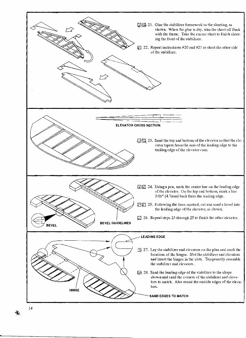

PLYWOOD DOUBLER
~ 29 Mark the locations of the four Plywood doublers on both sides of the elevators Using a sharp knife remove 116 (15111111) of Ba Isa to a How the doubler to sit flush with the elevator Glue the four doublers in place
RECESS TO FIT FLUSH
LEADING EDGE
$ 30 Cut out parts R-2 R-3 R-4 R-5 R-6 R-7 and R-8
~ 31 Place parts R-2 R-3 and R-4 on the pIa n and glue with CAy fi9~ 32 Cut a piec~ of316 x 34 x 35-78 (47111111 x 19111111
x 911mm) rudder Ic~d ing edge to length and glue to the printed side of the rudder as shown
Rmiddot4
38 x 34 (95mm x 19mm) BALSA STRIPS
rgt
STRIP
~ I
I I
R-6
rpm 33 Glue pieces R-5 R-6 R-7 and R-8 to the rudder in the appropriate positions
iii iii 34 Using the 18 x 316 x 35-78 (32111111 x 47111111 x 911mm) Balsa strips cut seven pieces to fit on lop of the rudder in the marked locations
reg- 35 Repeat steps 32 through 34 to finish the other side of the rudder
~ 36 Cut out part R-t laminate both pieces and pin to the plan Cut two pieces of3S x 34 x 35-78 (95null x 19mm x 911nun) to length and pin the the plan
g 37 Usingthe3S x 12 x 35-78 (9Smmx 127nunx 911mm) Balsa strip build the fin framework over the plan Cut the longer sections first and then use shorter cutoffs for the smaller pieces
3S Edge glue two pieces of 116 x 2-78 x 24-78 (lSmm x 73nUll x 632nun) Balsa sheet together as in step 20
_____ 38- x 12shy
~ (95mm X 127mm) BALSA STRIPS
[] Q 39 Glue the fin framework to the sheeting as shown When the glue is dry trim the sheet off flush with the frame Take the excess sheet to finish sheeting the front of the fin
~ 40 Fl ip the fin over and repeat instruction 39 to sheet the other side of the fin
m- 41 Sand the top and bottom of the rudder as in step 23 so tha t it tapers from the rear of the leading edge to the trailshying edge of the rudder core Using the same method as in steps 24 and 25 bevel the leading edge of the rudshyder
RUDDER CROSS SECTION
LEADING EDGE AND TOP OF RUDDER
42 Lay the rudder and fin on the plan and mark the locashytions of the hinges Slot the rudder and fin and insert the hinges in the slots Temporarily assemble the rudder and fin
GJ 43 Sand the leading edge of the fin and top of the rudder to the shape shown Round the top of the fin so that it makhes the top of the rudder
l ~
16
OUTBOARD SPAR
Qij145 Pin one 14 x 318 x 29-718 (64mm x 95nun x 759mm) outboard Spruce spar in position on top of the plan Make one end llush with the inboard end of the wing panel and let the excess extend beyond the wingtip
[]J2146 Glue one W-15 rib to one W-15A rib making sure the
44 Mark the locations of the two Plywood doublers on both sides of the rudder and glue them flush as shown in step 29
PLYWOOD DOUBLER
Wing Construction
Your T-6s wings are build directly on the plan using it as a pattern to position the parts Shortly after construction is started the drawing you are building on will be mvered by the parts that you are assembling For this reason we sugshygest that you build the left wing panel first and use the drawing of the opposite wing panel as a reference for part loeashytions There are two sets of check off boxes in this section Use one set of boxes while building the first panel and the other set while building the opposite panel
Note Most of the wing parts are pre cut to size Some of the parts will require cutting or trimming Do not cut or trim any of the parts unless told to do so
W-15A rib is on the outboard side ofW-i5
17
l
AILERON SPAR
OUTBOARD TRAILING EDGE
W-20 OUTBOARD LEADING EDGE
W-l0
DIHEDRAL GAUGE
W-l0
GJ CiJ 47 Position W-lO in place on the plan and set the angle witb the dihedral gauge Pin the trailing edge in place check the dihedral again and glue to the spar
NOTE When the dihedral gauge is properly positioned the top of the rib will lean toward the wing tip
48 Place ribs W-11 through W -20 on the plan using a small square to make sure they are 90deg to the building surface and glue to the spar
Cil ITJ49 Glue one 14 x 38 x 15-14 (6Amm x 95mm x 387mm) outboard trailing edge to ribs W-lO through W-15 Make the trailing edge flush at W-15 and alshylow the excess to go past WolD
taJ [] 50 Glue one 14 x 58 x 14-12u (6Anun x 159nlln x 368mm) tapered aileron spar to ribs W-15 through Wshy20 Make the widc~t end of the spar butt up against W-15
ill G 51 Glue the 38 x 1-14 x 30-78 (95mm x 318mmx 784mm) outboard leading edge to the front of ribs WshylD through W -20 Pin the inboard end of the leading edge so tbat it is centered on W-lO and resting on the building ooard at W-2D
W-l0
18
OUTBOARD SPAR GlWl 52 Set another outboard Spruce spar in place on top of the wing and use the dihedral gauge to check the diheshydral before gluing in place
[amp[~r 53 Edge glue one 3(32 x 2-78 x 30-78 (23nun x 73 nun x 784nun) outboard leading edge sheet to one 3(32 x 2-78 x 29-78 (23nun x 73mm x 759mm) outboard sheet Glue the sheets so that both pieces are flush at one end
LEADING EDGE
LEADING EDGE SHEETING
~s 54 Test fit the leading edge sheet longest side forward to the rear of the leading edge The forward edge of the sheet should butt tight against the leading edge along its entire length with excess sheet on the ends forward of the spar Hold the leading edge sheet in position as shown and edge glue it to the leading edge a long its entire length Do not glue the sheeting to the ribs or spar at this time
55 Roll the leading edge sheet back and lllark the centershyline of the spar on the sheet Using your straight edge trim the sheet on the centerline of the spar Save the excess sheeting for step 58
LEADING EDGE
SPAR
ijG 56 Use a small flat strip of scrap wood to apply white glue to the top of all ribs forward of the spar Roll the leading edge down so tha t it contacts the ribs and then quickly glue the rear edge to the top of the spar with CA making sure the sheeting is still firmly in contact with all of the ribs
LEADING EDGE SHEETING
19
OUTBOARD SHEET
NOTE
57 Glue one 3(32 x 2-78 x 29-78 (23mm x 73mm x 759mm) outboard sheet to the wing so that it is flush with the trailing edge and has equal overhang on both ends
Be sure to reposition any pins that may get covered up by sheeting
LEADING EDGE SHEET ~ 58 Trim another outboard sheet to fit forward of the preshyvious piece Test fit this piece then glue in place Then using the excess leading edge sheet from step 55 finish sheeting the top of the outboard wing panel
bHCl 59 Remove the wing panel frolll the building board Trim the excess sheet from the area where the ailershyons get attached
o Q 60 Mark a trim I ine on each rib tab as shown using a penshycil and straight edge Then cutting on the trim line remove the tabs from the ribs
l[8 61 Trim the top of the leading edge so that it is 3(32 (23nun) above the sheeting
------- LEADING EDGE
20
L
14
1014 (318mm)
WING JIG
30-78 (784mm)
PAPER TUBE
W-1S
~~ 62 Invert the wing on the building board and pin it down with pins inserted just ahead of the spars Slide the outboard wingjig under wing so that it is directly unshyder the aileron spar The tallest end of the wingjig should be under the W-lO and the narrow end under W-20 Pin the jig to the board and also pin the trailshying edge securely to the jig
W-20
8iHtJ 63 Cut a piece of paper that is approximately 5 x 22 (127mm x 559nun) Roll the paper into a small tube
and slide it into the holes in ribs W-lO through W-15 leaving a small amount extending past W-15 Glue the tube to the ribs
WID 64 Position seven or the 3mm x 2-1316 x 1-78 (3mm x 714mm x 476mm) Lite-plywood shear webs in the positions shown on the plan Using the spar as a guide mark the excess shear web and trim to fit beshytween the ribs and Hush with the spar Glue the shear
WEB webs in place
Ecl~ 65 Using one 14 x 14 x 11-78 (64mm x 64nun x 302mm) Spruce servo rail cut two pieces to fit on ribs W-15 and W-16 Immediately behind the spar cut two notches for the front servo rail and glue in place Using one a icron servo determine the posishytion of the rear servo ra ii cut notches in W-15 and Wshy16 and glue in place Cut two more pieces of servo rail to fit between the front and rear servo rail and glue in place
NOTE The positions of the servo rails in this step will vltlry depending on the brltlnd or type of servo you a re using
LEADING EDGE SHEET
LEADING EDGE SHEET
OUTBOARD SHEET
l
~ 66 Referring to the plan for position glue three 14 x 14 x 78 (64nml x 64mll1 x 222mm) hinge doushyblers in place
~ 129 67 Edge glue one332 x 2-7S x 30-7S (23mm x 73nml x 7S4mlll) outboard leading edge sheet to one 332 x 2-7S x 29-7S (23mlll x 73mm x 759mm) outboard sheet Glue the sheets so that both pieces are flush at one end
SiJ 6S Test fit the leading edge sheet longest side forward to the rear of the leading edge The forward edge of the sheet should butt tight against the leading edge along its entire length with excess sheet on the ends forward of the spar Hold the leading edge sheet in position as shown and edge glue it to the leading edge along its entire length Do not glue the sheeting to the ribs or spar at this time
fjfl 69 Roll the leading edge sheet back and mark the centershyline of the spar on the sheet Using your straight edge trim the sheet on the centerline of the spar Save the excess sheeting for step 72
EElGJ 70 Use a small flat strip of scrap wood to apply white glue to the top of all ribs forward of the spar Roll the leading edge down so tha tit contacts the ribs and then quickly glue the rear edge to the top of the spar with CA making sure the sheeting is still firmly in contact with all of the ribs
tp-71 Glue one 332 x 2-7C x 29-7C (23mlll x 73mm x 759mm) outboard sheet to the wingso that it is flush
with the trailing edge and has equal overhang on both ends
22
LEADING EDGE SHEET
~m 72 Trim another outboard sheetto fit forward of the preshyvious piece Test fit this piece then glue in place Then using the excess leading edge sheet from step 69 fini~h sheeting the bottom of the outboard wing panel
ina 73 Remove the wing panel from the building board and trim off the excess sheet around the aileron spar Also trim off the excess sheet and spar at both ends of the wing panel
lSEEl 74 Using the plan as a guide cut I small hole in the sheclshying nea r the servo rails Locate the servo ra ils with your knife and remove the sheeting between them
4J 0 75 Glue W-21 to W-20 with the front of W-21 flush with the front of the leading edge
~ Iillfl 76 C nd nd held ing edge 0 hud iugt hown
~ on he pln
SHAPE LEADING EDGE
f4l077 Glue the partially shaped Balsa wing tip to the wing panel making sure it is centered on W-21 Carve and
sand the wing tip to shape
WING TIP BLOCK
23
-------------
CENTERED AILERON
--I I
FORWARD VIEW
END VIEW
OUTBOARD TAPERED TRAILING EDGE
CENTERLINE
OVERHANG ON BOTTOM ijJ til 78 Glue one outboard tapered trailing edge to the trailing
edge of the wing panel Make sure that the top of the tapered trailing edge is flush with the top of the wing leaving a small amout of overhang on the bottom Sand the tapered trailing edge to match the taper of the wing
LB 79 Repeat instructions 45 through 78 to build the opposhysite wing panel on the other wing panel plan
~~ STEP SAND FLUSH
IP Li 80 Using a pen mark the centerline on the aileron leadshying edge and aileron spar
~ fil 81 Mark the locations of the hinges on the aileron and aileron spar Slot the aileron and aileron spar and inshysert the hinges into the slots
CENTERLINE OF END __ ~SPAR AND AILERON
VIEW
--i=1F==============~~~======~--~
WINGAILERON
EBfiJ 82 Temporarily attach the aileron to the wing Centering the aileron with the wing use a pen to mark the taper of the wing onto the leading edge of the aileron Usshying these lines as guides taper the aileron to match the wing Place the aileron back on the wing to check the taper
s8183 Using the same method as with the rudder and elevashytor sand a bevel into the leading edge and taper the aileron from the leading edge to the trailing edge as shown
SHAPED AILERON
24
~
EiHIJ 84 Using the plan as a reference mark the locations of the Plywood doublers on both sides of the aileron Remove the excess Balsa to allow the doubler to sit flush with the aileron and glue in place
til 85 Repeltlt steps80 through 84 to finish the aileron on the opposite wing panel
INBOARD SPAR
lEi 86 Pin one 14 x 38 x 21-78 (64mm x 95mm x
556mm) inboard Spruce spar on top of the wing center section plan
NOTE All of the laser cut parts will need prepared before glushying Wipe off the edges with a rag dipped in lacquer thinner and lightly sand with 220 grit sandpaper to scuff up the edges
m 87 Remove the remaining ribs from the die-cut sheets and locate laser eu t part W -9
[] 88 Laminate two pairs of W-9s using epoxy
W-7
is 89 Using epoxy glue W-7 and W-6 to W-5 in the order shown on the plan Altsemble a second set ofthese parts making sure you have one left part and one right
WmiddotS
25 ~
I
W-9
W-3
W-2
W-4
INBOARD TRAILING EDGE
E3 90 Using epoxy glue W-9 and W-8 to W-3 as shown Again make a left and right part
W-8 W-3
~ 91 Transfer the location of the 316 (47mm) hole to the asshysembled W-3 ribs and drill
V 92 Glue ribs W-1 W-2 W-3 W-4 and W-5 to the inboard spar Use a small square to make sure all the ribs are
W-5
90deg to the building surface and pin the rib tabs to the building surface
~ 93 Glue the 14 x 38 x 21-78 (64mm x 95nml x 556mm) inboard trailing edge to the rear of the ribs so that it is centered on the end of each rib Allow equal amounts of overhang on each end
~ 94 Glue the other 14 x 38 (64nun x 95nun) inboard spruce spar to the tops of the ribs as shown
26
l
LEADING EDGE
FALSE SPAR
INBOARD SHEET
tE 95 Glue the two 38 x 1-12 x 4-78 (95mm x 38nun x 124mm) inboard leading cdges to the front of ribs W-5 and W-3 Let the bottom of the leading edge rest on the building surface and leave equal amount overhang on both ends
fi 96 Glue one 14 x 14 x 6-14 (64mm x 64mm x 159mm) false spar in place on top of ribs W-1 and W-2
~ 97 Using a pen or pencil draw a centerline on the top inshy board Spruce spar
1---CENTERLINE
g 98 Glue one 3(32 x 2middot78 x 21middot78 (23nun x 73mm x 556mm) inboard sheet to the top of the center section aligning the front edge with [he spar centerline Leave an equal amount of overhang on both ends
INBOARD SHEET
~ 99 Glue two more inboard sheets to the top of lhe cenler sccmiddot tion immediately behind thc first shccl
100 Glue onc 3(32 x 2middot7(8 x 21middot78 (23111111 x 73IlUH
x 556mm) inboard sheet to thc rear of the inboard leading edge Align one edge outboard ofW-3 and
W-3 trim off the sheet just past W-5
~fS 101 Using the excess inboard sheet trim a piece to fit in between the sheet attached to the leading edge and the sheet at the spar centerline
IE 102 Repeat steps 100 and 101 to sheet behind the opposite inboard leading edge
27
B
B
D
if] 103 Remove the center section from the building surface Loeate the positions of the shear webs and bolt blocks on the plan and mark on the center section where they will be placed
~ 104 Trim the tabs from the bottom of the ribs using the same method as in step 60
ttl 105 Pin the 14 x 34 x 21-78 (64mm x 19mm x 556mm) inboard wing jig to the plan where shown Pin the center section in place on top of tbe plan and wing jig
o 106 Glue shear webs A B C and D to the center section in the positions marked previously Shear web D will need to be trinuned to fit in between ribs W-7 and W-9 and shear webs Band C should be centered between the top and bottom spar
INBOARD LANDING GEAR PLATE
107 Glue One 14 x 14 x 6-14 (64nun x 64mm x 159mm) false spar to ribs W-l and W-2 as shown
ffI 108 Epoxy both Plywood inboard landing gear plates to the center section where shown on the plan The outboard edge should be flush with W-9 and the rear edge llush with shear web B
STRAIGHT EDGE
l
OUTBOARD LANDING GEAR PLATE
tt[ 109 Epoxy both 14 x 716 x 2-1532 (64nnll x 111 nun x 627nun) Plywood outboard landing gear plates to the notch in W-7 making sure not to get too much epoxy on the underside Before the epoxy cures use a straight edge to make sure that the outboard landing gear plate is parallel to the inboard landing gear plate
rp 110 Epoxy the two 14 x 14 x 2-34 (64nml x 64mmx 699nun) Spruce outboard landing gear braces to the unshyderside of the Plywood outboard landing gear plates
OUTBOARD LANDING GEAR BRACE
28
FORWARD BOLT BLOCKS
AFT BOLT BLOCKS
HI 111 Epoxy the forward and aft bo It blocks to the center secshytion where marked previously
fsect 112 Roll a piece of 5 x 22 (127null x 559111111) paper into a tube and slide it through the holes in the center secshytion Leave equal amountlt of excess at both ends and glue in place
EP 113 Glue a piece of 332 x 2-78 x 21-78 (23 11l 111 X
73nUll x 556nun) inboard sheet to the center section so that the rear edge of the sheet is flush with the trail ing edge of the center section
INBOARD TAPERED TRAILING EDGE
i
I~--- CENTERLINE
~ 114 Glue two more inboard sheets to the center section imshymediately forward of the previous sheet TIIC second sheet should set on the spar leaving a sml1J lip
ill 115 Using a sera p piece of inboa rd sheet glue a piece to the top of ribs W-5 and W-6 just inside ofW-7
w- 116 Remove the center section from the building surface trim both ends flush with rib W-5 and sand olTany exshycess sheet at the trailing edge
Eft 117 Glue the inboard tapered trailing edge to the trailing edge of the center section l nd trim the excess at both ends flush with W-5
29
CENTERLINE
FUSELAGE TOP
Fuselage
Most of the parts in the fuselage are made from Micro-Lite Plywood This wood is very strong for its weight howshyever CA glue is absorbed quickly into the grain For this reason we reconunend the following method for gluing the Micro-Lite Ply fuselage parts together
1 Hold the parts to be joined in position 2 Run thin CA glue into the joint 3 Wait about 10 seconds and spray the joint lightly with accelerator 4 After the first application is completely dry apply another coat of thin or thick CA due to the joint
CAUTION Read all warnings and cautions on the label of the CA gluelt and accelerator you arc using Be sure to have adequate ventilation to avoid breathing the fumes
Your T-6s fuselage is constructed from interlocking die-cut parts that self align during construction insuring that the fuselage will be straight Because the parts interlock it is important that the construction sequence be followed carefully Before starting construction read through the fuselage assembly instructions to be sure you understand how all of the parts fit together and to identify a II of the parts During construction use the check off boxes to keep trdck of your progress It is essential that all joints are closed tight before glue application The easieltt way to achieve this is to grip each joint firmly with your finger and thumb and squeeze adjacent parts together
NOTE Very lightly sand the edges of all of the die cut parts to remove any burrs or rough spotlt Smoothing the edges of the parts in this manner will aid the CA glue in bonding the parts together Remember you only want to smooth the edges of thelte parts only removing the burrs
bit 118 Draw a 42 (1067nun) line near the center of your building board Mark the centerline on the Fuselage top in severallocalions and pin down on the building board lining it up with the centerline on the board
~
TAIL WHEEL BEARING
rn 119 Glue the Brass tail wheel bearing into the keel with the top flush with the rectangular cutout in the keel Glue the tail wheel doublers on lxlth sides of the tail wheel bearing as shown
TAIL WHEEL DOUBLER
TAtLWHEEL fr I DOUBLER ~ II 1
II ) ~
F-7B
F-7A
~ 120 Laminate F-7B and F-7A with epoxy making sure that the pushrod positions line up as shown
THRUST LINES
IB 121 Place F-2 on the plan and transrer the thrust Iincgt to F-2
F-2
14 (64mm) HOLE
FRAMES F-7 THROUGH F-11 14 (64mm) HOLE
532 (4mm) HOLE
as- 122 Drill the pushrod holes and antenna tube holes into F-7 through F-11 For the pushrod holes use a 14 (64nun) drill bit and for the antenna tube holes use a 532 (4mm) drill bit
31
I
NOTE Prep the laser cut parts (F-2 F-4 and F-6) as in step 87 before gluing to the fuselage top Also make sure that all of the push rod holes line up on the correct sides
IB 123 Glue F-1 through F-ll to the fuselage top using a small square to make sure they are 90deg to the building surshyface Use the plan as a reference to determine where ea ch former will be placed
-liJ 124 Set the master stringers in place but do not glue them at
125 Position F-12 in place between the master stringers as
MASTER STRINGER
this time
MASTER STRINGER
shown
~ 32
l
ID 126 Set the keel in place on top of the fanners but do not glue at this time Note the keel may need to be sanded at F-7 to allow the wing to sit flush in the wing saddle
~ 127 Check the fit of the fuselage parts to make sure that the
frames are 90deg to the building surface and all of the stringers are in place Tack glue all of the joints with CA
128 Glue two 14 x 14 x 15-78 (64nml x 64mm x 403mm) bottom stringers to the bottom of the fuselage in the notches shown Make one end flush with the first notch and trim the excess at the other end
FLUSH
LOWER SIDE STRINGER
til 129 Glue two 14 x 14 x 23-78 (64111111 x 64nllll x
606mm) lower side stringers into the notches shown You may need to spray the stringers at the forward end with ammonia based glass cleaner to get it to bend beshytween F-7 and F-8 Make one end flush with the first notch and trim off the excess at the opposite end Save the scrap for the next step
33 v ~
---KEEL
it 130 Using the scrap 14 x 14 (64mm x 64mm) Balsa cut two pieces to fit in between F-t and F-2 Glue both pieces to the sides of the keel with the top nush with Fshy1 and F-2
1 _F-1
W131 Glue two 14 x 14 x 37-78 (64111111 x 641ll1ll x 962mm) upper side stringers on each side of the fuseshylage as shown Make one end nush with the first notch and trim off the excess at the opposite end
Pit 132 Apply a second coat of CA to all the joint to secure the whole fuselage
til 133 Check the fit of the 116 (15mm) Plywood doubler on the Fuselage Starting at the rear of the doubler glue the straight edge to the master stringer Once the glue has dried bend the doubler to the shape of the frames and secure to F-7 F-6 and F-S
i 34 ~
l
STABILIZER PLATFORM
PUSHROO SUPPORTS
m134 From F-4 forward glue the two small sections to the frames Take the largest section and wrap it around the frames so that the inside edge is flush with the keel and the rear edge is flush with F-2 as shown Once the inshyside edge is secured finish gluing the rest of the doushybler to the frames
Il3 135 Remove the fuselage fonn the build ing board Glue Fshy13 to the rear of the keel as shown
til 136 Glue the stabilizer platform to the fuselage using a small square to make sure that the keel is 90deg to the building surface
137 Locate and cut out the pushrod supports from the print sheets Glue the pushrod supports in place at the rear of the fuselage with the edges flush with the master stringshyers stabilizer platform and F-ll
l
LOWER SIDE STRINGER
J 138 Glue the two 332 x 14 x 4-78 (23mm x 64mmx 124mm) filler strips to the lower side stringers just beshyhind the Plywood doubler Then using a sanding block fair the filler strips so tha t they are flush with the doubler and lower side stringer
FORWARD TOP SHEET
G1139 Sand the whole fuselage smooth and fair any high or low spots Trim the doubler flush with F-l
~ 140 Position one 18 x 2-1(2 x 23-78 (32Illm x 635nun x 606mIll) forward top sheet with the bottom edge censhytered on the lower stringer and the rear edge centered between F-7A and F-7B Glue the lower edge to the stringer wet the sheet with the window cleaner and alshylow to sit for 10 minutes Once the sheet becomclt flexshyible glue it the the fuselage top and frames Repeat this step for the opposite side
141 Transfer the rear top sheet template to the two 18 x 2shy1(2 x 26-78 (32mm x 635mm x 683nun) rear top sheets and cut out the parts Position the rear top sheet so that the bottom edge is centered on the lower stringer and the front edge bults up against the forward top sheet Glue the sheet to the stringer and soak with winshydow cleaner Once the sheet becomes flexible glue to the fuselage top and frames Repeat this step for the opshyposite side
----shy FORWARD TOP SHEET
36
PUSHROD TUBE
ANTENNA TUBE
q 142 Trim the front and rear top sheets flush with the fuseshy
lage top F-l F-ll and the stabilizer platform
-tj143 Locate the pushrod holes in the pushrod supports with your knife and open up holes to match in the fuse sheets Insert one pushrod tube into each of the pushrod supports and through the push rod holes in each of the frames Using the a piece of inner pushrod inshysert the antenna tube into the fuselage and through all of the antenna holes in each of the frames Use a piece of sandpaper to roughen up the ends of the pushrods and antenna tube where they will be glued to the fuseshylage Glue the tubes in place and trim off the excess
GLUE CENTER FIRST
II PUSH
I~ REAR TOP SHEET
Gl 144 Pin the fuselage to the building board making sure the the fuselage top is flaton the board
NOTE for the following steps make sure that you llIark the top a nd front edges on the tn mmed pieces of wood
IJ 145 Transfer the rear 2 sheet template to the two 18 x 3shy78 x 26-78 (32mlll x 984nllll x 6831l1ln) rear 2 sheets and cut out the parts Position the rear 2 sheet on top of the rear top sheet so that the front edge is censhytered between F-7A and F-7B Tack glue the center of the rear 2 sheet to the stringer and the rear top sheet Wet the sheet with window cleaner and let set for 10 minutes Starting a t the front bend the front and rear edge in contact with the stringer and rcar top sheet then glue in place Once the sheet is glued along the top edge roll into shape and glue to the fuselage Repeat this step for the opposite side
[t1146 Transfer the rear 3 shcettemplaLe to the two 18 x 2shy14 X 18-78 (321l1l1l x 572mm x 4791ll1ll) rear 3 sheets and cut out the parts Using the same method as in the previous step position the rca r 3 sheet on top of the rear 2 sheet so that an equal amount overhangs Fshy12 and F-8 Glue the center of the part to the lower side stringer and rear 2 shcet Wet with window deaner bend both ends in contact with the rear 2 sheet and glue in place Roll the sheet in contact with the frames and glue to the bottom stringer Repeat this step for the opposite side
l
TRIM EXCESS
REAR 3 SHEET
S 147 Edge glue the two 18 x 2-78 x 23-78 aft bottom sheet~ transfer the aft bottom sheet template and cut out the part Glue one edge to the rear 3 sheet as shown and wet with window cleaner Once the sheet becomes flexible roll the sheet around and glue to the opposite rear 3 sheet
NOTE This piece may require extra care to get it to bend into shape without splitting
o 148 Trim off the excess sheet around F-12 and the master stringers
FORWARD It2 SHEET
FORWARD TOP SHEET
-tE 149 Transfer the forward 2 sheet template to the two 18 x 2-78 x 23-78 (32mm x 73nml x 606mm) forward 2 sheets and cut out the parK Position the forward 2 sheet so that the back edge butts up against the rear 2 sheet and the top edge is against the forward top sheet Glue along the top edge and soak with window deaner When the sheet becomes flexible bend in place and glue to fuselage Repeat this step for the opposite side
FORWARD 3 SHEET
til 150 Position the 18 x 2-78 x 23-78 (32mmx 73mm x 606mm) forward 3 directly on top of the forward 2 sheet and glue the top edge to the fuselage Note there will be a small ga p in between Forward Sheet 2 and 3 Trim the sheet approximately 14 (64mm) above the wing saddle wet with window cleaner and glue to fuselage
bull
-I-w 38
FILL GAP FLUSH
MISC FUSELAGE SHEET
151 Using the 18 x 2-78 x 35-78 (32mm x 73mlH x 911mm) misc fuselage sheet cut two pieces to finish sheeting the forward fuselage
tfJ 152 Cut two pieces of 18 (32mm) Balsa to fill in the gaps between forward sheet 2 and forward sheet 3 and glue in place Trim the excess Balsa sheet [lush with F-l
~
153 Using scrap pieces of 18 (32m111) Balsa fill in the rear of the wing saddle so that it is flush with the rest of the fuselage
154 Trim the excess sheet around formers F-7 F-8 and the Plywood doubler
155 Cut and glue a piece of 18 (32mm) balsa to the botshy10m of the keel between F-7 and F-8 Sand this piece flush with the sheet at F-8 and taper it to nothing at F-7
156 Using a piece of sandpaper glued to a cardboard tube sand the balsa sheet Oush with the Plywood wing sadshydle Sand all the joints in the fuselage skin to remove any high or low spots
Eil 157 Temporarily position the left tail wheel block in posishytion between F-12 and F-13 Mark the location of the tail wheel doubler and recess the hlock so that it sits flush aga inst the keel Mark the center of the rectangushylar cutout in the keel and drill through the block with a 14 (64l11m) drill hit
158 Place the block on the fuselage again and mark where the excess can be removed Trim the block but leave an 18 (32I1ml) of excess on the block to be sanded off later Using the hole in the block as a center draw parshyallellines approximately 34 (19mm) long on both sides of the hole Use thclte Jines as a guide to cut out a triangular slot for the tail wheel steering arm
159 Temporarily position the right tail wheel block onto the fuselage mark the position of the tail wheel doubler and recess the block in the area marked Glue hoth tail wheel blocks to the fuselage and sand to shape Fill in the gap between the blocks with a scrap piece of Balsa
l 39
LEFT TAIL WHEEL BLOCK
m160 Using the lines marked previously carve out a slot in
~ the left tail wheel block for the rudder pushrod housing
Insert the rudder pushrod housing into the fuselage and glue in place
SLOT
tfPl--RUDDER PUSHROD HOUSING
STRINGER
STRINGER
Fmiddot19
ijJ 161 Center F-14 on top of the fuselage at F-ll and glue flush with the rear face of F-ll
[jJ 162 Position F-15 on top of F-IO and glue
163 PositionF-160n topofF-9and glue
~ 164 Glue one 14 x 14 x 11-78 (64nun x 64mm x 302mm) Balsa stringer to the tops of F-14 F-15 and Fshy16 Trim both ends flush with F-14 and F-16
ffi 165 Glue Fmiddot17 F-18 and F-19 to the fuselage in the posishytions marked on the plan
166 Glue one 14 x 14 x 11-78 (64nun x 64nun x 302mm) Balsa stringer in the notches of F-17 through Fshy19 Trim both ends flush with F-17 and F-19
0141 167 Bevel one edgeofa 18 x 2-78 x 11-78 (32nun x 73 nun x 302nun) top sheet as shown
fZfB 168 Glue the sheet to the rear of the fuselage and wet with glass e1eaner Wrap the sheet around the formshyers trim to the centerline of the Balsa stringer and glue in place
[] 169 Repeat steps 167 and 168 to sheet the opposite side
40
CENTERLINE
- ~
REAR COCKPIT ~~---------BLOCK
itHQJ 170 Edge glue one 18 x 2-78 x 11-78 (32mm x 73nun x 302nun) top sheet and one 18 x 78 x 11shy78 (3 2nun x 222mm x 302nun) top sheet Bevel one edge as in step 167
ftI til 171 Glue the sheet to the top of the fuselage and wet the sheet with window cleaner Wrap around the formshyers trim to the centerline of the Balsa stringer and glue in place
4J 172 Repeat steps 170 and 171 to sheet the opposite side
~ 173 Trim the tops sheets flush with F-14 F-16 F-17 and Fshy19
w- 174 Glue the 38 x 1-12 x 4-78 (95nun x 38mm x 124mm) rear cockpit block to the forward face of F-16 and sand to match the contours of the f(1pound deck
PLYWOOD FAIRING
iR 175 Slightly round the corners of the fuselage sheet at F-7
176 Mark a centerline on the 164 (Anun) Plywood fairing and on the fuselage at F-8 Position the fairing flush with the front edge of F-7 and line up the centerlines Use thick CA to glue the fairing to the keel and bottom ofF-7 Do not glue within 14 (64nun) of the ends of F-7
ROUND CORNERS
PL YWOOD FAIRING
m177 Wet the fairing with window deaner and let soak for a few minutes One side at a time wrap the fairing around the fuselage and glue in place
tcentl178 Sand the fuselage smooth a II over Blend the Plywood fairing to the fuse with a lightweight model filler
l
THRUST LINES FIREWALL SIDES
~ 179 The front of the prop washer will need to be 6-38 (162mm) from F-2 M(~sure from the rear of your moshy
FIREWALL
FIREWALL BOX
--y----- MOTOR MOUNT
ID 181 The following steps refer to bui IJ ing your model with the firewall box but will be the same whether you usc the box or not Using a 316 (47nun) drill bit drill four holes in the firewall (F-2) for the motor mount making sure that you line up the thrust lines on the moshytor mount and firewall
COVER FIREWALL
tor mount to the front of the prop washer If you cant get a distance of at least 6-38 (162mm) then you will need to use the firewall box to mount the motor Skip the next step if you do not need the firewall box
o 180 Lay the 14 x 3-34 x 3-34 (64mm x 952mlll x 952nml) Plywood Firewall on the plan and transfer the thrust lines Determine the depth of the firewall box needed to position the prop washer 6-38 (162null) from F-2 Then if needed cut or sand the 14 xl x 3shy12 (64mm x 254mm x 891llIll) Plywood firewall sides to the depth required and assemble the firewall box as shown
m 182 Using four 10-32 screws with blind nut attach the moshytor mount to the firewall fusing the firewalllxlx reshymove the motor mount align the thrust lines and epoxy to F-2
NOTE When attaching the motor mount your will want the enshygine to have 30 of right thrust and 3deg of down thrust To achieve this you will need to use spacers on the engine or motor mount
o 183 Temporarily mount the engine on the motor mount and mark the locatiolls of the throttle pushrod and fuel lines on the firewall
~ 184 Glue the four 34 x 34 x 34 (19nu11 x 19mm xl9mm) Spruce cowl blocks to F-l as shown with apshyproximately 14 (64nun) of overha ng on the outside edge Round the cowl blocks slightly to match the conshytours of the cowl
NOTE To help keep the engine cool it recommended that you cover up the recessed firewall with scraps of Litc-Ply or plastic glued to F-1 You will want to paint the inside of the firewall with a fuel proof paint prior to covering it up and leave openshyings for the fuel lines and pushrod
COWL BLOCKS
42
COWL____ o 185 Mark the top on the inside of the cowl Cut out a hole on the front just big enough to fit the engine through and trim off the excess on the rear edge Position the cowl on the cowl blocks and center on the engine at least 14 (64mm) from the prop Cut out the front of the cowl in the area directly in front of the engine leave the rest in place Drill through the cowl and cowl blocks with a 116 (15mm) drill bit and secure the cowl with four 2 sheet metal screws and four 2 washshyers Once the cowl is mounted make cutouts for the muffler glow plug and needle valve
l
__________
o 186 Remove the cowl and engine Drill 14 (64mm) holes for the fuel lines and throttle pushrod in the positions marked previously
187 Using a razor saw cut out the portion of the kee 1 forshyward of F-6 and aft of F-4 At the same time cut out the bottom ofF-5 approximately 12 (127nml) in from the sides
160Z FUEL TANK
o 188 Cut two pieces of 14 x 12 x 10 (64mm x 127mm x 254mm) foam and glue to the inside of the fuel tank cutouts in F-4 and F-3 Assemble the fuel tank and atshytach any fuel lines Slide the fuel tank into the notches and secure in place
o 189 Insert the fucllines through the appropriate holes in the firewall Install the throttle pushrod in the fuselage and glue in place Position the 14 x 58 x 6-78 (64mm x 159mm x 175mm) Plywood servo rails as shown on the plan and glue in place
43
----- TAPER TO NOTHING
SCRAP 332 (23mm) BALSA
fil 190 Glue two pieces of scrap 332 (23mm) Balsa together glue to the stabilizer platform and trim the sheet Oush with the sides of the fuselage Sand this piece so that it tapers from 316 (47rrun) at F-14 to nothing at the rear of the fuselage
CENTERLINE S 191 Draw a centerline on the stabilizer and stabil izer plalshyfonn
fil 192 Set the stabilizer on the stabilizer platform and press fit the stab root triangles between the stabilizer and fuseshylage Glue the stab root triangles to the stabilizer only and sand to match the stabilizer
m193 Place the fin on the fuselage Cut the 12 x 1-78 x 2shy112 (127mm x 476mm x 635mm) tail filler in half and place next to the fin behind the stabilizer Glue the tail filler to the stabilizer platfonn only
-----STABILIZER
_--- FLUSH
$ 194 Place the 58 x 1 x 7 (159mm x 254mm x 178mm) tail fairing blocks on opposite sides of the fin and glue to the fin only Carve and sand tbe tail fairing blocks from the circular shape at the front to being Oush with the rear edge oftbe fin Sand the front oftbe fin to blend in with the tail fairing blocks and fuselage
STABILIZER
_____ STAB ROOT
TRIANGLE
_____FIN
TAIL FAIRING BLOCK
2-56 NUT
I
CONTROL HORN
THREADED ROO
RUDDER
__2-56 SCREW
195 Place the e levators on the stabilizer and mark where the tail filler w ill need to he trimmed to allow for a small gap hetecn c( c-tr and tail filler Trim the tail filler anJ 3~-= J hottom to blend in with the eleatof and - ~ 5 Finally cut a radius in the tail filler Sti~- ~~ c ftllcr meets the rear of the elevator and ne - _ lt jh the rear of the fuseshylage
196 Set the rudder on the fin and place a fou rth hinge a t the rear of the fuselage
D 197 Remove the elevator and rudder Using the plan as a guide mount control horns on each elevator Forthe rudder you will need one control horn on each side Hold two control horns together as they will be on the rudder and drill two new holes in one to match the opshyposite control horn Attach the rudder control horns with the 2-56 x 34 (2-56 x 19mm) screws and 2-56 nuts Secure the nuts with CA or epoxy
D 198 Make up two elevator and one rudder push rod accordshying to the manufacturers instructions Attach a clevis to each pushrod and install the push rods in their housings
NOTE For added strength insert the unthreaded end into the pushrod as shown Bend the rod so that it operdtcs smoothly with the clevis
LEADING EDGE
I GROOVE
D 199 Cut two strips of scrap 332 (23nlln) Balsa approxishymately 12 (127nllu) wide and glue to the rear of the center section leading edge
o 200 Carve and shape the leading edge to match the outshyboard wing panels Trim the leading edge flush with F-3
o 201 Cut a 332 groove in the leading edge to continue the lip for the plastic wheel well fairing
l 45
Fixed Landing Gear
l
LANDING GEAR POSITION
NYLON LANDING GEAR STRAP
~FIXED LANDING GEAR PLATE
D 203 Using the template on the plan as a guide drill the holes in the Ply-ood fixed landing gear plate for the landing gear and mounting screws Also transfer the lines for the landing gear
204 Drill through the torque blocks with a 316 (47nun) drill bit where the landing gear gets inserted into the landing gear plate
D 205 Set the landing gear in the center section as shown and transfer the locations ofthe mounting screws Drill a pishylot hole for these screws with a 3321 (23 nUll) drill bit
D 206 Set the landing gear in place aligning them with the lines marked previously and set the nylon landing gear straps on top of the landing gear Mark the locations for the 2-56 x 34 (2-56 x 19nun) landing gear screws and drill the holes with a 332 (23mm) bit
D 207 Carefully open up the two holes that go through the trishyangle stock with a 14 (64nml) drill bit make sure that you onJy drill through the balsa and not the plyshywood Paint the landing gear plates with a fuel proof paint Bolt the landing gear to the landing gear plates with the 2-56 screws 2 washers and 2-56 nuts
46
This section shows how to build and install the fixed landing gear for the plane If you will be using the retract landing gear on your plane you may skip this section and go on to the next section
202 Epoxy the 12 x I x 2-78 (127mm x 254mm x 73mm) Maple torque blocks to the bottom of each landshying gear plate making sure that you make a left and right Epoxy the 34 x 34 x 2-78 (19mm x 19mm x 73nml) triangle stock to the bottom of the landing gear plate as shown
j I I
Retractable Land ing Gear
3 (7smm)
FILLER VALVE
AIR TANKS
o 208 Folio ing ttt ~~ _ ~~ r r i nslructions attach a short piece of air ~ ~ the air tanks Followshying the diagram connect ttc f ( tanks with a 1 atshytach another short piece (t ar rc anJ connect a secondT to the end ortba -llb a tbird piece of air line to the second T and connect tbe ppositc end to the air filler valve
o 209 Slide the tanks into position through the top of the fuseshylage and glue in place with Silicon rubber Drill a 516 (80mm) hole in the fuselage side just above the wing and attach the air filler valve to the fuselage
AIR FILLER VALVE
RECTANGULAR CUTOUT
o 210 Position the retract units in the wing center section censhytered between the mounts and 116 (15mm) forward of the shear web Mark the locations of the mounting screws Remove the retract units and driJl332 (2Jnml) pilot holes for the 6 x 58 (6 x 159nun) and 6 xl (6 xl) mounting screws
NOTE You may need to file away the edges of the rectangushylar cutout to get the retract to fit in the wing Be careful not to remove too much of the wing You will also want to file off the end of the screw that is directly above the air cylinder
47
Mounting the Wing
~ fUSELAGE BOLT PLATES
~
fiBERGLASS TAPE
I I ~ 14 (64mm) ~ ~_____ SPRUCE
0211 Epoxy two of the L4 x 1-14 x 1-l2 (64mmx 318mm x 38mm) Plywood fuselage bolt plates toshygether and while the epoxy is still wet secure to the frames and fuselage as shown Repeat this step for the remaining three fuselage bolt plates
o 212 Using scrap pieces of 14 x 14 (64mm x 64l1uu) Spruce eJXlxy one supJXlrt under each fuselage bolt plate on the fuselage sides
o 213 Draw a centerline on the bottom of the wing center secshytion Using the plan as a reference measure and mark the locations of the rear wing 00 It blocks Lay the wing center section on the fuselage and glue the wing oolt reshyinforcements in the locations marked for the rear wing bolts
o 214 Drill through the wing bolt blocks and fuselage bolt blocks with a 316 (47mm) drill bit Remove the wing and on the wing only open up the wing bolt holes with a 14 (64nun) drill bit Thread the holes in the fuselage with a 14-20 lap
NOTE You will want to drill two 12 (127mm) holes in the bottom of fuselage to allow the oil from the engine to drain
----~----~-------
o 215 Trim the fairing as shown and mark a centerline on the top Set the fa iring on the center section I ining up the center lines and trim the sides to sit flush in the center section Cut a 1 (254nun) wide strip of fiberglass tape and glue it to the bottom side edges of the fairing as shown
48
4-40 SCREW
WHEEL WELL SHEET
o
TRIM 216 Mount tbe center section t)l1lhe fuselage with the two rear wing bo]L~ Slick the fairing in place and position it so that tbe front edge is lush ith the wingsaddle Mark and trim the rear tJ~e d the fairing to sit flush on the wing
217 Using a generous amount of filled epx set the fairing on the eenter section and push it down until it sets flush with the wing sheeting Once the epxy dries drill through the forward bolt blocks to open up holes in the fairing
218 Set the center section on the fuselage again and mark on the fairing where the bottom of the fuselage conshytacts the fairing Trim the fa iring nus hat the lowest part of the fuselage as shown Cut the outenuost part of the fairing away from the center and wrap around the wing as shown
NOTE As an option you may want to glue another strip of fishyberglass to the bottom of the fairing around the wheel wells Also if W-l doesnt fully contact the fairing you will want to use some epoxy to glue it to the fairing
TRIM FLUSH
D 219 If there Ls more than a 3(32 (23nun) gap between the bottom of the fairing and W-1 you will need to glue and sand a filler strip to achieve this dimension Fishynally paint the bottom side of the fairing and around the landing gear mounts with a fuel proofpaint
D 220 Edge glue two pieces of 332 x 2-78 x 14-78 (23mm x 73nun x 378mm) wheel well sheet and using the plan as a template cut out the wheel well sheet Set the wheel well sheet in place on the center section and trim to fit with the wing and retracts Paint the top side of the wheel well sheet with a fuelproof paint before gluing in place Opcn up the holes in the wheel well sheet for the wing bol Is
D 221 Insert the wheel collar into the tail wheel slot and slide the tail wheel wire down through the tail wheel bearing and wheel collar Screw the 4-40 xl (4-40 x 254mm) tail wheel link into the 332 (23mm) wheel collar and tighten on the tail wheel wire Rotate the wheel to deshytermine how far it rotates If you do not have at least 250 of rotation you will need to open up the slot Reshymove the tail wheel assembly and paint the slot with a fuel proof pa int
49
l
l
~-----
Joining the wings
CANOPY
222 Trim the canopy at the front back and bottom edges Now is the time when you will want to add a cockpit floor or any other structures to the cockpit
o 223 Paint the cockpit floor with a fuel proof paint
COCKPIT FLOOR
o 224 Set the wing center section on the plastic wrap covered building board making sure the wheel well faces down Insert the building jig under the center section and place heavy non damaging weights (telephone books are ideal) on top to immobilize it
WmiddotS Wmiddotl0
~~~~~~~[___~~ 1
CLshy___~~~~~~_______Lt_=__L[_===m~--~ o 225 Test fit the wing panels by butting the ends together
Check the diItance between the underside of the raised wing panel at W-21 and the building board It should be 2-112 to 3-112 (635nun to 89nun) If the dihedral does not fa II within this range the root ribs must be bevshyeled with a large sanding block If necessary a Balsa shim rib must be cut from scrap Balsa and glued to Wmiddot 10 trimmed to the wing profile and then sanded to a wedge shape
CORRECTIVE SHIM
50
FIBERGLASS TAPE
2~6 SJl1lt~H [ r fil m of epoxy on the mating faces of each 1 rJ [Cn join the wings inserting pins
through tDc k1~r~lnd trliling edges to maintain the 1 bk (ject to support the raised
cures wipe away excess epoxy with paper to d t thi step for the oppo-
SUPPORT
E~ J - ~
alignment Lee 6
wing tip and heflrc
site wing panel
o 227 Tack glue one end of the fiberglass tape to the trail ing edge of the wing with thin CA Now stretch it tightly around the wing a nd tack glue it to the trailing edge on the opposite side Once secured the tape can be flooded with thin CA to stick it down Repcat this step for the opposite wing panel
o 228 Once the glue dries trim the fiberglass tape around the inside edges of the landing gear mounl
Finishing
o 229 Sand the model smooth all over in preparation for covering
NOTE The fin and stabilizer on the prototype were covered before gluing to the fuselage but you may choose glue the tail surfaces on the fuselage before covering
o 230 The prototype model was covered with Cub Yellow and Black Monokotereg covering film However other brands of covering film will work equally well and you should be guided by your hobby dealer Large surshyfaces were covered first using the remaining materia I to cover the smaller components Follow the film manufacturers instructions when covering When covering around the wing fairing you will want the covshyering to overlap the plastic by a 116 (15nun) For the markings guide see page 52 Using the black covshyering make the anti-glare panel and wing walks Cut 132 (8mm) strips of black covering and apply the panel lines to the plane as shown on the markings guide
o 231 The decals provided are of the peel-and-stick type and we recommend the following method of applica tion 1 - Put 4 or 5 drops of dish washing liquid into a smalJ cereal bowl and then half-fill with warm water mixshying thoroughly 2 - Cut closely around each decal with a new 11 hobby knife blade and then peel it from the backing sheet as needed 3 - Liberally swab the are~ to which the decal is to be applied with the soapy solution before placing the deshycal in position The mixture will allow the decal to be slid into its final position 4 - Hold the decal firmly in place and use a piece of flexible plastic (can be cut from a polyethylene coffee can or butter tub lid) to squeegee the water out from underneath blotting with paper towel as required Alshylow the decal to dry in a warm place for at least 48 hours
51
l
RIGHT
TOP WING
LEFT
o
10
)
J
LEFT AND RIGHT SIDE
BOTTOM
2
17
UNDERSIDE OF RIGHT WING ONLY
MARKINGS GUIDE
)
TOP OF LEFT WING ONLY
NOTE SHADED AREAS ARE BLACK
N l11
Final assembly
STABILIZER
STABILIZER
l
REMOVE COVER ING FROM TOP AND BOTIOM
I
FlN~ ~
VIEW FROM REAR
D 232
STABILIZER
WING
Attach the wing to the fuselage and then ltuefully reshymove the covering rna erial from the center of the sta bishylizer to expose the wood before gluing to the fuselage Before the glue dries carefully sight across the stabishylizer from the rear to align the stabilizer with the wing
FIN
STABILIZER
D 233 Trim away the covering material to expose the wood and then glue the fin to the fuselage Before the glue dries check to see tha t it is vertical (90 0 to the stabishylizer) When the glue has set remove the wing
D 234 Hinge the rudder and elevators to the fin and stabilizer
_---shy ELEVATOR
RECEIVER AND BATIERY
D 235 Wrap the receiver and battery in foam and secure in the fuselage Install the servos on the servo rails as shown on the plan
D 236 Attach a pushrod to each of the elevators making sure tha t they are paralic I and connect each pushrod to an elevator servo
D 237 Attach the rudder pushrod to the control horn on the left side of the rudder Connect the rudder pushrod to the rudder servo
53
TAIL WHEEL --_
TAIL WHEEL WIRE ~
~ BALL LINK AND CONNECTOR
AIR SCOOP
l 54
D 238 Attach the 1-34 (444null) tail wheel to the tail wheel wire with two 332 (23rrun) wheel collars Assemble tbe tail wheel assembly as in step 221 and tighten the 4-40 screw Clip off the head of the 4-40 screw and atshytach the 4-40 ball link
D 239 Add a Du-Bro Efl Connector to the control hom on the right side of the rudder and screw the ball socket to the 6 (152nun) threaded rod Snap tbe ha 1I socket on the ball link and slide the threaded rod through the Efl Connector Align the rudder and tail wheel secure the threaded rod to the Efl Connector and trim off the exshycess
D 240 Mount the motor on the motor mount and attach the muffler and propeller
D 241 Hook up the fuel lines in the appropriate position Conshynect a pushrod to the throttle and throttle servo
D 242 Using the plan as a guide carve and sand the air scoop to shape Cover the scoop and glue to the fuselage
o 243 For added strength you will want to glue a strip of fibershyglass to the inside of the cowl Secure the Cowl to the fuselage
NOTE The following steps refer to install ing the air va lve for the retracts If you are installing fixed gear you can skip these steps
o 244 Using the plan as a reference epoxy the two 38 x 38 xI (95mmx 95nun x 254nun) Spruce retract servo mounts to the fuselage Attach the retract servo to the retra ct servo mounts
D 245 Using the template on the plan and a scrap piece of 3nun Lite-Plywood cut out the air valve mount Drill a 38 (95nun) hole in one end and glue the a ir valve mount to F-5 as shown on the plan
D 246 Secure the a ir valve to the mount and connect the servo with a Nylon clevis ElZ Connector and threaded rod
o 247 Attach the a ir I inc from the air tanks to the center fitting on the air valve Cut four pieces of air line to 12 (305nun) and attach a quick disconnect one end of each Attach the four air lines to the remaining fittings on the air valve
o 248 Cut a small hole in thc tnp cf the wing to allow the air lines to go through the ing Reinstall the retract units in the wing and secure with the =6 x 5- 2 (6 x 159mm) and 6 xl (6 x 25Arnm) screws
o 249 Cut two pieces of air line to 20 (508mm) two more to 12 (305mm) and attach a quick disconnect to one end of each Attach each air line to the retract air cylinders as shown on the plan
o 250 Connect each quick disconnect to the appropriate air I ine and bolt the wing to the fuselage Attach the 4 (102nun) wheels to the retract units Following the manufacturers instructions test the gear and adjust the struts to make sure that the wheels are pardllel
o 251 Mount the fixed gulf units in the wing with the 6 x 58 (6 x 159nun) and 6 xl (6 x 254nun) screws Attach the 4 (102nun) wheels to the landing gear wires with 316 (47mm) wheel collars
NOTE Landing gear fairings are included in the kit and may be installed if desired
o 252 Secure the a ilerons to the wing and attach the control horns
o 253 Mount the aileron servos in the wing and screw a clevis to the 10 (254rnnl) threaded rod Connect the control rod to the aileron servo and control horn
l
RETRACT UNIT ----shy
4 (102mm) WH EEL ________
THREADED ROD ~
CLEVIS~ ~
shy shy shy shy shy shy
gt shy shy shy
~ gt
o
55
PENNED
CANOPY
o 254 Position the canopy on the fuselage pressing it finnly down into position before tracing around it with a fine fiber-tip pen
LINE
l
TAPE
CANOPY
~
ANTI-GLARE PANEL
---~-
CAGLUE~--
o 255 Remove the canopy and cut away all the covering mateshyrial from within the cockpit areas starting 116 (l5mm) imide the penned line
o 256 Paint any exposed wood within the cockpit and (hen apshyply the instrumentation panel decal to the cockpit If deshysired an optional pilot and other accessories ean be added at this time
PENNED LINE
o 257 Re-position the canopy on the fuselage taping it in place Then using thin CA applied sparingly glue the canopy in place keeping the glue at Icast 12 (127mm) away from any tape Rcmove the tape as soon as the glue has set and then apply glue to the reshymaining areas
o 258 Mask off the cowl and wing fairing leaving a 116 (15 nun) border to allow the paint to overlap the covershying Mask off the window panels on the canopy and again allow the paint to over lap the covering Paint the canopy cowl and fairing with the appropriate color matching paint
259 Mask off the top of the canopy and cowl for the antishyglare panel and paint black
56
D 260 Turn the receiver and transmitter on to set the control throws to achieve the following measurements
Ailerons 78 (222mm) up and 1 2 (I27mm) down Elevator - 34 (19mm) up and 34 (19nm1) down
Rudder - 78 (222mm) up and 78 (222mm) down
12 (127mm) DOWEL~
---shyWOODBLOCK
ANGLE ENDS
261 When the model is complete and in a ready-to-fly mndition it is ready for balancing at the balancing point shown on the plan
NOTE Balancing must be done with the fuel tank empty
Balancing this model is best carried out with the model inverted It can be done by resting the wings on two finger tips in line with the balance point but a better method is to make up the simple balancing stand shown here from readily available materials The wings should be set on the dowels in line with the balance point and if the model does not sit absolutely horizontal when viewed from the side the battery pack should be moved backward or forshyward until it does then re-packed with foam to retain the pack in place
Flying the Midwest AT-6
Introduction
The Midwest AT-6 is a good flying model that will provide you with many enjoyable tl ights provided that you follow these gu ide1ines Before your first flight it is very important that the model balances at the location shown on the plan and the control surface throws 111USt be set to the recommended measurements Make sure that your motor is broken in and running reliably and range check the radio
The Take-OfT
Your AT-6 will taxi easily and the steering is positive une up into the wind and increase the power slowly Steering is positive and the model should be kept tracking straight with slight rudder mrrections The tail will come up by itself When flying speed is reached gently apply up elevator as needed to lift off
57
l
Flight
Climb out at a shallow angle Because the model has a Oat bottom airfoil the model will try to climb slightly as power is added Trim the model to fly straight and level at about 34 throttle The Midwest AT-6 is very maneushyverable but it is important that the model be tlCl n smoothly Throttle back at a safe altitude and try some slow flight and a stall or two If one wing drops s ha rpl y at the stall adjust the rudder trim to minimize the wing drop Then readjust the ailerons for level flight you will not be able to completely eliminate the wing drop at the stall but you will be able to minimize it Your model should be capable of tight pylon turns using full up elevator with out snapping out Reduce the elevator throw if requited Putting too much elevator throw in this model will produce unshydesirable snap rolling so caution should be used when increasing the elevator throw above the recommended setting
Landing
Make several practice approaches to get the feel for the model During the approach a small amount of power should be kept on until the model is over the runway Reduce the power and hold the model level over the runway at an altitude of 12 The model should touch down at a fairly slow speed on the main gear with the tail wheel still slightly in the air Lower the tail slowly and steer with the rudder as required until the model has slowed to taxi speed
The staff at Midwest Products hope you have enjoyed build ing your Midwest AT-6 and sincerely wish you the best of times flying it We would appreciate you taking a few minutes to fill out and return the Postage-Paid Evaluation Card in this kit We welcome any suggestions or comments you may have for improving our kiL~ and construction manua L
Thank you
l
Acknowledgements
The following ind ividuals contributed to the development of this kit and the production of this construction manual
Model Designed By Tom Herr
Illustrations By Ross Heironimus
Manua I Assembled By Ross Heironimus
copy 1993 Midwest Products Co Inc
58
Allie Kelledy Cblcago Heights IL
Micromiddotcut Qualm- ood -
eyery time Triplemiddotinspected so youll hae fun building
Midwest Mustang 60
-
3 Flies like a dream
Warbirds
4 As easy to build and fly as my Aerostarreg
Four reasons why RC pilots preferSuccess Seriesreg Warbird kits
Kit 174
l
Midwest Corsair 40 Kit t 75 Midwest Mustang 40 Kit 170 MidwestMeaaerschmltt40 Kit171 Midwest Zero 40 Kit 172 Wingspan 60 Wingspan 54 Wingspan 54 Wingspan 60 Wing Area 552 sq in Wing Area 521 SQ in Wing Area 521 sq in Wing Area 552 sQ in Flying Weight 5-5 Ibs Flying Weight 5-5V2 Ibs FlYing Weight 5-5112 Ibs Flying Weight 5-5 Ibs Radio 4 Channel Radio 4 Channel Radio 4 Channel Radio 4 Channel Motor Range 2-Cycle - 35 - 45 Motor Range 2Cycle - 35 45 Motor Range 2middotCyclemiddot 35 - 45 Motor Range 2-Cycle - 35 - 45
4-Cycle AO - 50 4middotCyclemiddot 40 - 50 4middotCyclemiddot 40 - 50 4-Cycle 40 - 50
1 Cut just perfect
components really fit
as well as fhing
2 Builds very fast BL LeRolLY Halija( Voa Scotia
Fewer parts speeds building time ComputermiddotdraTI fullmiddotsize plans amp illustrated construction manual eliminate guesswork
Wingspan 65 Wing Area 727 SQ In Flying Weight 6-7 Ibs RadIo 4 Channel (5 Channel for Retracts) Motor Range 2middotCyclemiddot 60 90
4middotCyclemiddot 65 90
l1li MIDWEST ~ PRODUCTS CO INC 4005lndlanaSt PO Box564 Hobart1N46342 219)942-lf34 FAX219947-2347
Leland G Alonroe Selah WA
Stable yet maneuverable with a gentle stalL Theres no eaiier way to get into
Uichael S Thompson Cariboll vlE
Success Series kits make it easy for you to [he the Warbird adventure Stop by your hobby retailer and get your flight plan today

l
AILERON SPAR
OUTBOARD TRAILING EDGE
W-20 OUTBOARD LEADING EDGE
W-l0
DIHEDRAL GAUGE
W-l0
GJ CiJ 47 Position W-lO in place on the plan and set the angle witb the dihedral gauge Pin the trailing edge in place check the dihedral again and glue to the spar
NOTE When the dihedral gauge is properly positioned the top of the rib will lean toward the wing tip
48 Place ribs W-11 through W -20 on the plan using a small square to make sure they are 90deg to the building surface and glue to the spar
Cil ITJ49 Glue one 14 x 38 x 15-14 (6Amm x 95mm x 387mm) outboard trailing edge to ribs W-lO through W-15 Make the trailing edge flush at W-15 and alshylow the excess to go past WolD
taJ [] 50 Glue one 14 x 58 x 14-12u (6Anun x 159nlln x 368mm) tapered aileron spar to ribs W-15 through Wshy20 Make the widc~t end of the spar butt up against W-15
ill G 51 Glue the 38 x 1-14 x 30-78 (95mm x 318mmx 784mm) outboard leading edge to the front of ribs WshylD through W -20 Pin the inboard end of the leading edge so tbat it is centered on W-lO and resting on the building ooard at W-2D
W-l0
18
OUTBOARD SPAR GlWl 52 Set another outboard Spruce spar in place on top of the wing and use the dihedral gauge to check the diheshydral before gluing in place
[amp[~r 53 Edge glue one 3(32 x 2-78 x 30-78 (23nun x 73 nun x 784nun) outboard leading edge sheet to one 3(32 x 2-78 x 29-78 (23nun x 73mm x 759mm) outboard sheet Glue the sheets so that both pieces are flush at one end
LEADING EDGE
LEADING EDGE SHEETING
~s 54 Test fit the leading edge sheet longest side forward to the rear of the leading edge The forward edge of the sheet should butt tight against the leading edge along its entire length with excess sheet on the ends forward of the spar Hold the leading edge sheet in position as shown and edge glue it to the leading edge a long its entire length Do not glue the sheeting to the ribs or spar at this time
55 Roll the leading edge sheet back and lllark the centershyline of the spar on the sheet Using your straight edge trim the sheet on the centerline of the spar Save the excess sheeting for step 58
LEADING EDGE
SPAR
ijG 56 Use a small flat strip of scrap wood to apply white glue to the top of all ribs forward of the spar Roll the leading edge down so tha t it contacts the ribs and then quickly glue the rear edge to the top of the spar with CA making sure the sheeting is still firmly in contact with all of the ribs
LEADING EDGE SHEETING
19
OUTBOARD SHEET
NOTE
57 Glue one 3(32 x 2-78 x 29-78 (23mm x 73mm x 759mm) outboard sheet to the wing so that it is flush with the trailing edge and has equal overhang on both ends
Be sure to reposition any pins that may get covered up by sheeting
LEADING EDGE SHEET ~ 58 Trim another outboard sheet to fit forward of the preshyvious piece Test fit this piece then glue in place Then using the excess leading edge sheet from step 55 finish sheeting the top of the outboard wing panel
bHCl 59 Remove the wing panel frolll the building board Trim the excess sheet from the area where the ailershyons get attached
o Q 60 Mark a trim I ine on each rib tab as shown using a penshycil and straight edge Then cutting on the trim line remove the tabs from the ribs
l[8 61 Trim the top of the leading edge so that it is 3(32 (23nun) above the sheeting
------- LEADING EDGE
20
L
14
1014 (318mm)
WING JIG
30-78 (784mm)
PAPER TUBE
W-1S
~~ 62 Invert the wing on the building board and pin it down with pins inserted just ahead of the spars Slide the outboard wingjig under wing so that it is directly unshyder the aileron spar The tallest end of the wingjig should be under the W-lO and the narrow end under W-20 Pin the jig to the board and also pin the trailshying edge securely to the jig
W-20
8iHtJ 63 Cut a piece of paper that is approximately 5 x 22 (127mm x 559nun) Roll the paper into a small tube
and slide it into the holes in ribs W-lO through W-15 leaving a small amount extending past W-15 Glue the tube to the ribs
WID 64 Position seven or the 3mm x 2-1316 x 1-78 (3mm x 714mm x 476mm) Lite-plywood shear webs in the positions shown on the plan Using the spar as a guide mark the excess shear web and trim to fit beshytween the ribs and Hush with the spar Glue the shear
WEB webs in place
Ecl~ 65 Using one 14 x 14 x 11-78 (64mm x 64nun x 302mm) Spruce servo rail cut two pieces to fit on ribs W-15 and W-16 Immediately behind the spar cut two notches for the front servo rail and glue in place Using one a icron servo determine the posishytion of the rear servo ra ii cut notches in W-15 and Wshy16 and glue in place Cut two more pieces of servo rail to fit between the front and rear servo rail and glue in place
NOTE The positions of the servo rails in this step will vltlry depending on the brltlnd or type of servo you a re using
LEADING EDGE SHEET
LEADING EDGE SHEET
OUTBOARD SHEET
l
~ 66 Referring to the plan for position glue three 14 x 14 x 78 (64nml x 64mll1 x 222mm) hinge doushyblers in place
~ 129 67 Edge glue one332 x 2-7S x 30-7S (23mm x 73nml x 7S4mlll) outboard leading edge sheet to one 332 x 2-7S x 29-7S (23mlll x 73mm x 759mm) outboard sheet Glue the sheets so that both pieces are flush at one end
SiJ 6S Test fit the leading edge sheet longest side forward to the rear of the leading edge The forward edge of the sheet should butt tight against the leading edge along its entire length with excess sheet on the ends forward of the spar Hold the leading edge sheet in position as shown and edge glue it to the leading edge along its entire length Do not glue the sheeting to the ribs or spar at this time
fjfl 69 Roll the leading edge sheet back and mark the centershyline of the spar on the sheet Using your straight edge trim the sheet on the centerline of the spar Save the excess sheeting for step 72
EElGJ 70 Use a small flat strip of scrap wood to apply white glue to the top of all ribs forward of the spar Roll the leading edge down so tha tit contacts the ribs and then quickly glue the rear edge to the top of the spar with CA making sure the sheeting is still firmly in contact with all of the ribs
tp-71 Glue one 332 x 2-7C x 29-7C (23mlll x 73mm x 759mm) outboard sheet to the wingso that it is flush
with the trailing edge and has equal overhang on both ends
22
LEADING EDGE SHEET
~m 72 Trim another outboard sheetto fit forward of the preshyvious piece Test fit this piece then glue in place Then using the excess leading edge sheet from step 69 fini~h sheeting the bottom of the outboard wing panel
ina 73 Remove the wing panel from the building board and trim off the excess sheet around the aileron spar Also trim off the excess sheet and spar at both ends of the wing panel
lSEEl 74 Using the plan as a guide cut I small hole in the sheclshying nea r the servo rails Locate the servo ra ils with your knife and remove the sheeting between them
4J 0 75 Glue W-21 to W-20 with the front of W-21 flush with the front of the leading edge
~ Iillfl 76 C nd nd held ing edge 0 hud iugt hown
~ on he pln
SHAPE LEADING EDGE
f4l077 Glue the partially shaped Balsa wing tip to the wing panel making sure it is centered on W-21 Carve and
sand the wing tip to shape
WING TIP BLOCK
23
-------------
CENTERED AILERON
--I I
FORWARD VIEW
END VIEW
OUTBOARD TAPERED TRAILING EDGE
CENTERLINE
OVERHANG ON BOTTOM ijJ til 78 Glue one outboard tapered trailing edge to the trailing
edge of the wing panel Make sure that the top of the tapered trailing edge is flush with the top of the wing leaving a small amout of overhang on the bottom Sand the tapered trailing edge to match the taper of the wing
LB 79 Repeat instructions 45 through 78 to build the opposhysite wing panel on the other wing panel plan
~~ STEP SAND FLUSH
IP Li 80 Using a pen mark the centerline on the aileron leadshying edge and aileron spar
~ fil 81 Mark the locations of the hinges on the aileron and aileron spar Slot the aileron and aileron spar and inshysert the hinges into the slots
CENTERLINE OF END __ ~SPAR AND AILERON
VIEW
--i=1F==============~~~======~--~
WINGAILERON
EBfiJ 82 Temporarily attach the aileron to the wing Centering the aileron with the wing use a pen to mark the taper of the wing onto the leading edge of the aileron Usshying these lines as guides taper the aileron to match the wing Place the aileron back on the wing to check the taper
s8183 Using the same method as with the rudder and elevashytor sand a bevel into the leading edge and taper the aileron from the leading edge to the trailing edge as shown
SHAPED AILERON
24
~
EiHIJ 84 Using the plan as a reference mark the locations of the Plywood doublers on both sides of the aileron Remove the excess Balsa to allow the doubler to sit flush with the aileron and glue in place
til 85 Repeltlt steps80 through 84 to finish the aileron on the opposite wing panel
INBOARD SPAR
lEi 86 Pin one 14 x 38 x 21-78 (64mm x 95mm x
556mm) inboard Spruce spar on top of the wing center section plan
NOTE All of the laser cut parts will need prepared before glushying Wipe off the edges with a rag dipped in lacquer thinner and lightly sand with 220 grit sandpaper to scuff up the edges
m 87 Remove the remaining ribs from the die-cut sheets and locate laser eu t part W -9
[] 88 Laminate two pairs of W-9s using epoxy
W-7
is 89 Using epoxy glue W-7 and W-6 to W-5 in the order shown on the plan Altsemble a second set ofthese parts making sure you have one left part and one right
WmiddotS
25 ~
I
W-9
W-3
W-2
W-4
INBOARD TRAILING EDGE
E3 90 Using epoxy glue W-9 and W-8 to W-3 as shown Again make a left and right part
W-8 W-3
~ 91 Transfer the location of the 316 (47mm) hole to the asshysembled W-3 ribs and drill
V 92 Glue ribs W-1 W-2 W-3 W-4 and W-5 to the inboard spar Use a small square to make sure all the ribs are
W-5
90deg to the building surface and pin the rib tabs to the building surface
~ 93 Glue the 14 x 38 x 21-78 (64mm x 95nml x 556mm) inboard trailing edge to the rear of the ribs so that it is centered on the end of each rib Allow equal amounts of overhang on each end
~ 94 Glue the other 14 x 38 (64nun x 95nun) inboard spruce spar to the tops of the ribs as shown
26
l
LEADING EDGE
FALSE SPAR
INBOARD SHEET
tE 95 Glue the two 38 x 1-12 x 4-78 (95mm x 38nun x 124mm) inboard leading cdges to the front of ribs W-5 and W-3 Let the bottom of the leading edge rest on the building surface and leave equal amount overhang on both ends
fi 96 Glue one 14 x 14 x 6-14 (64mm x 64mm x 159mm) false spar in place on top of ribs W-1 and W-2
~ 97 Using a pen or pencil draw a centerline on the top inshy board Spruce spar
1---CENTERLINE
g 98 Glue one 3(32 x 2middot78 x 21middot78 (23nun x 73mm x 556mm) inboard sheet to the top of the center section aligning the front edge with [he spar centerline Leave an equal amount of overhang on both ends
INBOARD SHEET
~ 99 Glue two more inboard sheets to the top of lhe cenler sccmiddot tion immediately behind thc first shccl
100 Glue onc 3(32 x 2middot7(8 x 21middot78 (23111111 x 73IlUH
x 556mm) inboard sheet to thc rear of the inboard leading edge Align one edge outboard ofW-3 and
W-3 trim off the sheet just past W-5
~fS 101 Using the excess inboard sheet trim a piece to fit in between the sheet attached to the leading edge and the sheet at the spar centerline
IE 102 Repeat steps 100 and 101 to sheet behind the opposite inboard leading edge
27
B
B
D
if] 103 Remove the center section from the building surface Loeate the positions of the shear webs and bolt blocks on the plan and mark on the center section where they will be placed
~ 104 Trim the tabs from the bottom of the ribs using the same method as in step 60
ttl 105 Pin the 14 x 34 x 21-78 (64mm x 19mm x 556mm) inboard wing jig to the plan where shown Pin the center section in place on top of tbe plan and wing jig
o 106 Glue shear webs A B C and D to the center section in the positions marked previously Shear web D will need to be trinuned to fit in between ribs W-7 and W-9 and shear webs Band C should be centered between the top and bottom spar
INBOARD LANDING GEAR PLATE
107 Glue One 14 x 14 x 6-14 (64nun x 64mm x 159mm) false spar to ribs W-l and W-2 as shown
ffI 108 Epoxy both Plywood inboard landing gear plates to the center section where shown on the plan The outboard edge should be flush with W-9 and the rear edge llush with shear web B
STRAIGHT EDGE
l
OUTBOARD LANDING GEAR PLATE
tt[ 109 Epoxy both 14 x 716 x 2-1532 (64nnll x 111 nun x 627nun) Plywood outboard landing gear plates to the notch in W-7 making sure not to get too much epoxy on the underside Before the epoxy cures use a straight edge to make sure that the outboard landing gear plate is parallel to the inboard landing gear plate
rp 110 Epoxy the two 14 x 14 x 2-34 (64nml x 64mmx 699nun) Spruce outboard landing gear braces to the unshyderside of the Plywood outboard landing gear plates
OUTBOARD LANDING GEAR BRACE
28
FORWARD BOLT BLOCKS
AFT BOLT BLOCKS
HI 111 Epoxy the forward and aft bo It blocks to the center secshytion where marked previously
fsect 112 Roll a piece of 5 x 22 (127null x 559111111) paper into a tube and slide it through the holes in the center secshytion Leave equal amountlt of excess at both ends and glue in place
EP 113 Glue a piece of 332 x 2-78 x 21-78 (23 11l 111 X
73nUll x 556nun) inboard sheet to the center section so that the rear edge of the sheet is flush with the trail ing edge of the center section
INBOARD TAPERED TRAILING EDGE
i
I~--- CENTERLINE
~ 114 Glue two more inboard sheets to the center section imshymediately forward of the previous sheet TIIC second sheet should set on the spar leaving a sml1J lip
ill 115 Using a sera p piece of inboa rd sheet glue a piece to the top of ribs W-5 and W-6 just inside ofW-7
w- 116 Remove the center section from the building surface trim both ends flush with rib W-5 and sand olTany exshycess sheet at the trailing edge
Eft 117 Glue the inboard tapered trailing edge to the trailing edge of the center section l nd trim the excess at both ends flush with W-5
29
CENTERLINE
FUSELAGE TOP
Fuselage
Most of the parts in the fuselage are made from Micro-Lite Plywood This wood is very strong for its weight howshyever CA glue is absorbed quickly into the grain For this reason we reconunend the following method for gluing the Micro-Lite Ply fuselage parts together
1 Hold the parts to be joined in position 2 Run thin CA glue into the joint 3 Wait about 10 seconds and spray the joint lightly with accelerator 4 After the first application is completely dry apply another coat of thin or thick CA due to the joint
CAUTION Read all warnings and cautions on the label of the CA gluelt and accelerator you arc using Be sure to have adequate ventilation to avoid breathing the fumes
Your T-6s fuselage is constructed from interlocking die-cut parts that self align during construction insuring that the fuselage will be straight Because the parts interlock it is important that the construction sequence be followed carefully Before starting construction read through the fuselage assembly instructions to be sure you understand how all of the parts fit together and to identify a II of the parts During construction use the check off boxes to keep trdck of your progress It is essential that all joints are closed tight before glue application The easieltt way to achieve this is to grip each joint firmly with your finger and thumb and squeeze adjacent parts together
NOTE Very lightly sand the edges of all of the die cut parts to remove any burrs or rough spotlt Smoothing the edges of the parts in this manner will aid the CA glue in bonding the parts together Remember you only want to smooth the edges of thelte parts only removing the burrs
bit 118 Draw a 42 (1067nun) line near the center of your building board Mark the centerline on the Fuselage top in severallocalions and pin down on the building board lining it up with the centerline on the board
~
TAIL WHEEL BEARING
rn 119 Glue the Brass tail wheel bearing into the keel with the top flush with the rectangular cutout in the keel Glue the tail wheel doublers on lxlth sides of the tail wheel bearing as shown
TAIL WHEEL DOUBLER
TAtLWHEEL fr I DOUBLER ~ II 1
II ) ~
F-7B
F-7A
~ 120 Laminate F-7B and F-7A with epoxy making sure that the pushrod positions line up as shown
THRUST LINES
IB 121 Place F-2 on the plan and transrer the thrust Iincgt to F-2
F-2
14 (64mm) HOLE
FRAMES F-7 THROUGH F-11 14 (64mm) HOLE
532 (4mm) HOLE
as- 122 Drill the pushrod holes and antenna tube holes into F-7 through F-11 For the pushrod holes use a 14 (64nun) drill bit and for the antenna tube holes use a 532 (4mm) drill bit
31
I
NOTE Prep the laser cut parts (F-2 F-4 and F-6) as in step 87 before gluing to the fuselage top Also make sure that all of the push rod holes line up on the correct sides
IB 123 Glue F-1 through F-ll to the fuselage top using a small square to make sure they are 90deg to the building surshyface Use the plan as a reference to determine where ea ch former will be placed
-liJ 124 Set the master stringers in place but do not glue them at
125 Position F-12 in place between the master stringers as
MASTER STRINGER
this time
MASTER STRINGER
shown
~ 32
l
ID 126 Set the keel in place on top of the fanners but do not glue at this time Note the keel may need to be sanded at F-7 to allow the wing to sit flush in the wing saddle
~ 127 Check the fit of the fuselage parts to make sure that the
frames are 90deg to the building surface and all of the stringers are in place Tack glue all of the joints with CA
128 Glue two 14 x 14 x 15-78 (64nml x 64mm x 403mm) bottom stringers to the bottom of the fuselage in the notches shown Make one end flush with the first notch and trim the excess at the other end
FLUSH
LOWER SIDE STRINGER
til 129 Glue two 14 x 14 x 23-78 (64111111 x 64nllll x
606mm) lower side stringers into the notches shown You may need to spray the stringers at the forward end with ammonia based glass cleaner to get it to bend beshytween F-7 and F-8 Make one end flush with the first notch and trim off the excess at the opposite end Save the scrap for the next step
33 v ~
---KEEL
it 130 Using the scrap 14 x 14 (64mm x 64mm) Balsa cut two pieces to fit in between F-t and F-2 Glue both pieces to the sides of the keel with the top nush with Fshy1 and F-2
1 _F-1
W131 Glue two 14 x 14 x 37-78 (64111111 x 641ll1ll x 962mm) upper side stringers on each side of the fuseshylage as shown Make one end nush with the first notch and trim off the excess at the opposite end
Pit 132 Apply a second coat of CA to all the joint to secure the whole fuselage
til 133 Check the fit of the 116 (15mm) Plywood doubler on the Fuselage Starting at the rear of the doubler glue the straight edge to the master stringer Once the glue has dried bend the doubler to the shape of the frames and secure to F-7 F-6 and F-S
i 34 ~
l
STABILIZER PLATFORM
PUSHROO SUPPORTS
m134 From F-4 forward glue the two small sections to the frames Take the largest section and wrap it around the frames so that the inside edge is flush with the keel and the rear edge is flush with F-2 as shown Once the inshyside edge is secured finish gluing the rest of the doushybler to the frames
Il3 135 Remove the fuselage fonn the build ing board Glue Fshy13 to the rear of the keel as shown
til 136 Glue the stabilizer platform to the fuselage using a small square to make sure that the keel is 90deg to the building surface
137 Locate and cut out the pushrod supports from the print sheets Glue the pushrod supports in place at the rear of the fuselage with the edges flush with the master stringshyers stabilizer platform and F-ll
l
LOWER SIDE STRINGER
J 138 Glue the two 332 x 14 x 4-78 (23mm x 64mmx 124mm) filler strips to the lower side stringers just beshyhind the Plywood doubler Then using a sanding block fair the filler strips so tha t they are flush with the doubler and lower side stringer
FORWARD TOP SHEET
G1139 Sand the whole fuselage smooth and fair any high or low spots Trim the doubler flush with F-l
~ 140 Position one 18 x 2-1(2 x 23-78 (32Illm x 635nun x 606mIll) forward top sheet with the bottom edge censhytered on the lower stringer and the rear edge centered between F-7A and F-7B Glue the lower edge to the stringer wet the sheet with the window cleaner and alshylow to sit for 10 minutes Once the sheet becomclt flexshyible glue it the the fuselage top and frames Repeat this step for the opposite side
141 Transfer the rear top sheet template to the two 18 x 2shy1(2 x 26-78 (32mm x 635mm x 683nun) rear top sheets and cut out the parts Position the rear top sheet so that the bottom edge is centered on the lower stringer and the front edge bults up against the forward top sheet Glue the sheet to the stringer and soak with winshydow cleaner Once the sheet becomes flexible glue to the fuselage top and frames Repeat this step for the opshyposite side
----shy FORWARD TOP SHEET
36
PUSHROD TUBE
ANTENNA TUBE
q 142 Trim the front and rear top sheets flush with the fuseshy
lage top F-l F-ll and the stabilizer platform
-tj143 Locate the pushrod holes in the pushrod supports with your knife and open up holes to match in the fuse sheets Insert one pushrod tube into each of the pushrod supports and through the push rod holes in each of the frames Using the a piece of inner pushrod inshysert the antenna tube into the fuselage and through all of the antenna holes in each of the frames Use a piece of sandpaper to roughen up the ends of the pushrods and antenna tube where they will be glued to the fuseshylage Glue the tubes in place and trim off the excess
GLUE CENTER FIRST
II PUSH
I~ REAR TOP SHEET
Gl 144 Pin the fuselage to the building board making sure the the fuselage top is flaton the board
NOTE for the following steps make sure that you llIark the top a nd front edges on the tn mmed pieces of wood
IJ 145 Transfer the rear 2 sheet template to the two 18 x 3shy78 x 26-78 (32mlll x 984nllll x 6831l1ln) rear 2 sheets and cut out the parts Position the rear 2 sheet on top of the rear top sheet so that the front edge is censhytered between F-7A and F-7B Tack glue the center of the rear 2 sheet to the stringer and the rear top sheet Wet the sheet with window cleaner and let set for 10 minutes Starting a t the front bend the front and rear edge in contact with the stringer and rcar top sheet then glue in place Once the sheet is glued along the top edge roll into shape and glue to the fuselage Repeat this step for the opposite side
[t1146 Transfer the rear 3 shcettemplaLe to the two 18 x 2shy14 X 18-78 (321l1l1l x 572mm x 4791ll1ll) rear 3 sheets and cut out the parts Using the same method as in the previous step position the rca r 3 sheet on top of the rear 2 sheet so that an equal amount overhangs Fshy12 and F-8 Glue the center of the part to the lower side stringer and rear 2 shcet Wet with window deaner bend both ends in contact with the rear 2 sheet and glue in place Roll the sheet in contact with the frames and glue to the bottom stringer Repeat this step for the opposite side
l
TRIM EXCESS
REAR 3 SHEET
S 147 Edge glue the two 18 x 2-78 x 23-78 aft bottom sheet~ transfer the aft bottom sheet template and cut out the part Glue one edge to the rear 3 sheet as shown and wet with window cleaner Once the sheet becomes flexible roll the sheet around and glue to the opposite rear 3 sheet
NOTE This piece may require extra care to get it to bend into shape without splitting
o 148 Trim off the excess sheet around F-12 and the master stringers
FORWARD It2 SHEET
FORWARD TOP SHEET
-tE 149 Transfer the forward 2 sheet template to the two 18 x 2-78 x 23-78 (32mm x 73nml x 606mm) forward 2 sheets and cut out the parK Position the forward 2 sheet so that the back edge butts up against the rear 2 sheet and the top edge is against the forward top sheet Glue along the top edge and soak with window deaner When the sheet becomes flexible bend in place and glue to fuselage Repeat this step for the opposite side
FORWARD 3 SHEET
til 150 Position the 18 x 2-78 x 23-78 (32mmx 73mm x 606mm) forward 3 directly on top of the forward 2 sheet and glue the top edge to the fuselage Note there will be a small ga p in between Forward Sheet 2 and 3 Trim the sheet approximately 14 (64mm) above the wing saddle wet with window cleaner and glue to fuselage
bull
-I-w 38
FILL GAP FLUSH
MISC FUSELAGE SHEET
151 Using the 18 x 2-78 x 35-78 (32mm x 73mlH x 911mm) misc fuselage sheet cut two pieces to finish sheeting the forward fuselage
tfJ 152 Cut two pieces of 18 (32mm) Balsa to fill in the gaps between forward sheet 2 and forward sheet 3 and glue in place Trim the excess Balsa sheet [lush with F-l
~
153 Using scrap pieces of 18 (32m111) Balsa fill in the rear of the wing saddle so that it is flush with the rest of the fuselage
154 Trim the excess sheet around formers F-7 F-8 and the Plywood doubler
155 Cut and glue a piece of 18 (32mm) balsa to the botshy10m of the keel between F-7 and F-8 Sand this piece flush with the sheet at F-8 and taper it to nothing at F-7
156 Using a piece of sandpaper glued to a cardboard tube sand the balsa sheet Oush with the Plywood wing sadshydle Sand all the joints in the fuselage skin to remove any high or low spots
Eil 157 Temporarily position the left tail wheel block in posishytion between F-12 and F-13 Mark the location of the tail wheel doubler and recess the hlock so that it sits flush aga inst the keel Mark the center of the rectangushylar cutout in the keel and drill through the block with a 14 (64l11m) drill hit
158 Place the block on the fuselage again and mark where the excess can be removed Trim the block but leave an 18 (32I1ml) of excess on the block to be sanded off later Using the hole in the block as a center draw parshyallellines approximately 34 (19mm) long on both sides of the hole Use thclte Jines as a guide to cut out a triangular slot for the tail wheel steering arm
159 Temporarily position the right tail wheel block onto the fuselage mark the position of the tail wheel doubler and recess the block in the area marked Glue hoth tail wheel blocks to the fuselage and sand to shape Fill in the gap between the blocks with a scrap piece of Balsa
l 39
LEFT TAIL WHEEL BLOCK
m160 Using the lines marked previously carve out a slot in
~ the left tail wheel block for the rudder pushrod housing
Insert the rudder pushrod housing into the fuselage and glue in place
SLOT
tfPl--RUDDER PUSHROD HOUSING
STRINGER
STRINGER
Fmiddot19
ijJ 161 Center F-14 on top of the fuselage at F-ll and glue flush with the rear face of F-ll
[jJ 162 Position F-15 on top of F-IO and glue
163 PositionF-160n topofF-9and glue
~ 164 Glue one 14 x 14 x 11-78 (64nun x 64mm x 302mm) Balsa stringer to the tops of F-14 F-15 and Fshy16 Trim both ends flush with F-14 and F-16
ffi 165 Glue Fmiddot17 F-18 and F-19 to the fuselage in the posishytions marked on the plan
166 Glue one 14 x 14 x 11-78 (64nun x 64nun x 302mm) Balsa stringer in the notches of F-17 through Fshy19 Trim both ends flush with F-17 and F-19
0141 167 Bevel one edgeofa 18 x 2-78 x 11-78 (32nun x 73 nun x 302nun) top sheet as shown
fZfB 168 Glue the sheet to the rear of the fuselage and wet with glass e1eaner Wrap the sheet around the formshyers trim to the centerline of the Balsa stringer and glue in place
[] 169 Repeat steps 167 and 168 to sheet the opposite side
40
CENTERLINE
- ~
REAR COCKPIT ~~---------BLOCK
itHQJ 170 Edge glue one 18 x 2-78 x 11-78 (32mm x 73nun x 302nun) top sheet and one 18 x 78 x 11shy78 (3 2nun x 222mm x 302nun) top sheet Bevel one edge as in step 167
ftI til 171 Glue the sheet to the top of the fuselage and wet the sheet with window cleaner Wrap around the formshyers trim to the centerline of the Balsa stringer and glue in place
4J 172 Repeat steps 170 and 171 to sheet the opposite side
~ 173 Trim the tops sheets flush with F-14 F-16 F-17 and Fshy19
w- 174 Glue the 38 x 1-12 x 4-78 (95nun x 38mm x 124mm) rear cockpit block to the forward face of F-16 and sand to match the contours of the f(1pound deck
PLYWOOD FAIRING
iR 175 Slightly round the corners of the fuselage sheet at F-7
176 Mark a centerline on the 164 (Anun) Plywood fairing and on the fuselage at F-8 Position the fairing flush with the front edge of F-7 and line up the centerlines Use thick CA to glue the fairing to the keel and bottom ofF-7 Do not glue within 14 (64nun) of the ends of F-7
ROUND CORNERS
PL YWOOD FAIRING
m177 Wet the fairing with window deaner and let soak for a few minutes One side at a time wrap the fairing around the fuselage and glue in place
tcentl178 Sand the fuselage smooth a II over Blend the Plywood fairing to the fuse with a lightweight model filler
l
THRUST LINES FIREWALL SIDES
~ 179 The front of the prop washer will need to be 6-38 (162mm) from F-2 M(~sure from the rear of your moshy
FIREWALL
FIREWALL BOX
--y----- MOTOR MOUNT
ID 181 The following steps refer to bui IJ ing your model with the firewall box but will be the same whether you usc the box or not Using a 316 (47nun) drill bit drill four holes in the firewall (F-2) for the motor mount making sure that you line up the thrust lines on the moshytor mount and firewall
COVER FIREWALL
tor mount to the front of the prop washer If you cant get a distance of at least 6-38 (162mm) then you will need to use the firewall box to mount the motor Skip the next step if you do not need the firewall box
o 180 Lay the 14 x 3-34 x 3-34 (64mm x 952mlll x 952nml) Plywood Firewall on the plan and transfer the thrust lines Determine the depth of the firewall box needed to position the prop washer 6-38 (162null) from F-2 Then if needed cut or sand the 14 xl x 3shy12 (64mm x 254mm x 891llIll) Plywood firewall sides to the depth required and assemble the firewall box as shown
m 182 Using four 10-32 screws with blind nut attach the moshytor mount to the firewall fusing the firewalllxlx reshymove the motor mount align the thrust lines and epoxy to F-2
NOTE When attaching the motor mount your will want the enshygine to have 30 of right thrust and 3deg of down thrust To achieve this you will need to use spacers on the engine or motor mount
o 183 Temporarily mount the engine on the motor mount and mark the locatiolls of the throttle pushrod and fuel lines on the firewall
~ 184 Glue the four 34 x 34 x 34 (19nu11 x 19mm xl9mm) Spruce cowl blocks to F-l as shown with apshyproximately 14 (64nun) of overha ng on the outside edge Round the cowl blocks slightly to match the conshytours of the cowl
NOTE To help keep the engine cool it recommended that you cover up the recessed firewall with scraps of Litc-Ply or plastic glued to F-1 You will want to paint the inside of the firewall with a fuel proof paint prior to covering it up and leave openshyings for the fuel lines and pushrod
COWL BLOCKS
42
COWL____ o 185 Mark the top on the inside of the cowl Cut out a hole on the front just big enough to fit the engine through and trim off the excess on the rear edge Position the cowl on the cowl blocks and center on the engine at least 14 (64mm) from the prop Cut out the front of the cowl in the area directly in front of the engine leave the rest in place Drill through the cowl and cowl blocks with a 116 (15mm) drill bit and secure the cowl with four 2 sheet metal screws and four 2 washshyers Once the cowl is mounted make cutouts for the muffler glow plug and needle valve
l
__________
o 186 Remove the cowl and engine Drill 14 (64mm) holes for the fuel lines and throttle pushrod in the positions marked previously
187 Using a razor saw cut out the portion of the kee 1 forshyward of F-6 and aft of F-4 At the same time cut out the bottom ofF-5 approximately 12 (127nml) in from the sides
160Z FUEL TANK
o 188 Cut two pieces of 14 x 12 x 10 (64mm x 127mm x 254mm) foam and glue to the inside of the fuel tank cutouts in F-4 and F-3 Assemble the fuel tank and atshytach any fuel lines Slide the fuel tank into the notches and secure in place
o 189 Insert the fucllines through the appropriate holes in the firewall Install the throttle pushrod in the fuselage and glue in place Position the 14 x 58 x 6-78 (64mm x 159mm x 175mm) Plywood servo rails as shown on the plan and glue in place
43
----- TAPER TO NOTHING
SCRAP 332 (23mm) BALSA
fil 190 Glue two pieces of scrap 332 (23mm) Balsa together glue to the stabilizer platform and trim the sheet Oush with the sides of the fuselage Sand this piece so that it tapers from 316 (47rrun) at F-14 to nothing at the rear of the fuselage
CENTERLINE S 191 Draw a centerline on the stabilizer and stabil izer plalshyfonn
fil 192 Set the stabilizer on the stabilizer platform and press fit the stab root triangles between the stabilizer and fuseshylage Glue the stab root triangles to the stabilizer only and sand to match the stabilizer
m193 Place the fin on the fuselage Cut the 12 x 1-78 x 2shy112 (127mm x 476mm x 635mm) tail filler in half and place next to the fin behind the stabilizer Glue the tail filler to the stabilizer platfonn only
-----STABILIZER
_--- FLUSH
$ 194 Place the 58 x 1 x 7 (159mm x 254mm x 178mm) tail fairing blocks on opposite sides of the fin and glue to the fin only Carve and sand tbe tail fairing blocks from the circular shape at the front to being Oush with the rear edge oftbe fin Sand the front oftbe fin to blend in with the tail fairing blocks and fuselage
STABILIZER
_____ STAB ROOT
TRIANGLE
_____FIN
TAIL FAIRING BLOCK
2-56 NUT
I
CONTROL HORN
THREADED ROO
RUDDER
__2-56 SCREW
195 Place the e levators on the stabilizer and mark where the tail filler w ill need to he trimmed to allow for a small gap hetecn c( c-tr and tail filler Trim the tail filler anJ 3~-= J hottom to blend in with the eleatof and - ~ 5 Finally cut a radius in the tail filler Sti~- ~~ c ftllcr meets the rear of the elevator and ne - _ lt jh the rear of the fuseshylage
196 Set the rudder on the fin and place a fou rth hinge a t the rear of the fuselage
D 197 Remove the elevator and rudder Using the plan as a guide mount control horns on each elevator Forthe rudder you will need one control horn on each side Hold two control horns together as they will be on the rudder and drill two new holes in one to match the opshyposite control horn Attach the rudder control horns with the 2-56 x 34 (2-56 x 19mm) screws and 2-56 nuts Secure the nuts with CA or epoxy
D 198 Make up two elevator and one rudder push rod accordshying to the manufacturers instructions Attach a clevis to each pushrod and install the push rods in their housings
NOTE For added strength insert the unthreaded end into the pushrod as shown Bend the rod so that it operdtcs smoothly with the clevis
LEADING EDGE
I GROOVE
D 199 Cut two strips of scrap 332 (23nlln) Balsa approxishymately 12 (127nllu) wide and glue to the rear of the center section leading edge
o 200 Carve and shape the leading edge to match the outshyboard wing panels Trim the leading edge flush with F-3
o 201 Cut a 332 groove in the leading edge to continue the lip for the plastic wheel well fairing
l 45
Fixed Landing Gear
l
LANDING GEAR POSITION
NYLON LANDING GEAR STRAP
~FIXED LANDING GEAR PLATE
D 203 Using the template on the plan as a guide drill the holes in the Ply-ood fixed landing gear plate for the landing gear and mounting screws Also transfer the lines for the landing gear
204 Drill through the torque blocks with a 316 (47nun) drill bit where the landing gear gets inserted into the landing gear plate
D 205 Set the landing gear in the center section as shown and transfer the locations ofthe mounting screws Drill a pishylot hole for these screws with a 3321 (23 nUll) drill bit
D 206 Set the landing gear in place aligning them with the lines marked previously and set the nylon landing gear straps on top of the landing gear Mark the locations for the 2-56 x 34 (2-56 x 19nun) landing gear screws and drill the holes with a 332 (23mm) bit
D 207 Carefully open up the two holes that go through the trishyangle stock with a 14 (64nml) drill bit make sure that you onJy drill through the balsa and not the plyshywood Paint the landing gear plates with a fuel proof paint Bolt the landing gear to the landing gear plates with the 2-56 screws 2 washers and 2-56 nuts
46
This section shows how to build and install the fixed landing gear for the plane If you will be using the retract landing gear on your plane you may skip this section and go on to the next section
202 Epoxy the 12 x I x 2-78 (127mm x 254mm x 73mm) Maple torque blocks to the bottom of each landshying gear plate making sure that you make a left and right Epoxy the 34 x 34 x 2-78 (19mm x 19mm x 73nml) triangle stock to the bottom of the landing gear plate as shown
j I I
Retractable Land ing Gear
3 (7smm)
FILLER VALVE
AIR TANKS
o 208 Folio ing ttt ~~ _ ~~ r r i nslructions attach a short piece of air ~ ~ the air tanks Followshying the diagram connect ttc f ( tanks with a 1 atshytach another short piece (t ar rc anJ connect a secondT to the end ortba -llb a tbird piece of air line to the second T and connect tbe ppositc end to the air filler valve
o 209 Slide the tanks into position through the top of the fuseshylage and glue in place with Silicon rubber Drill a 516 (80mm) hole in the fuselage side just above the wing and attach the air filler valve to the fuselage
AIR FILLER VALVE
RECTANGULAR CUTOUT
o 210 Position the retract units in the wing center section censhytered between the mounts and 116 (15mm) forward of the shear web Mark the locations of the mounting screws Remove the retract units and driJl332 (2Jnml) pilot holes for the 6 x 58 (6 x 159nun) and 6 xl (6 xl) mounting screws
NOTE You may need to file away the edges of the rectangushylar cutout to get the retract to fit in the wing Be careful not to remove too much of the wing You will also want to file off the end of the screw that is directly above the air cylinder
47
Mounting the Wing
~ fUSELAGE BOLT PLATES
~
fiBERGLASS TAPE
I I ~ 14 (64mm) ~ ~_____ SPRUCE
0211 Epoxy two of the L4 x 1-14 x 1-l2 (64mmx 318mm x 38mm) Plywood fuselage bolt plates toshygether and while the epoxy is still wet secure to the frames and fuselage as shown Repeat this step for the remaining three fuselage bolt plates
o 212 Using scrap pieces of 14 x 14 (64mm x 64l1uu) Spruce eJXlxy one supJXlrt under each fuselage bolt plate on the fuselage sides
o 213 Draw a centerline on the bottom of the wing center secshytion Using the plan as a reference measure and mark the locations of the rear wing 00 It blocks Lay the wing center section on the fuselage and glue the wing oolt reshyinforcements in the locations marked for the rear wing bolts
o 214 Drill through the wing bolt blocks and fuselage bolt blocks with a 316 (47mm) drill bit Remove the wing and on the wing only open up the wing bolt holes with a 14 (64nun) drill bit Thread the holes in the fuselage with a 14-20 lap
NOTE You will want to drill two 12 (127mm) holes in the bottom of fuselage to allow the oil from the engine to drain
----~----~-------
o 215 Trim the fairing as shown and mark a centerline on the top Set the fa iring on the center section I ining up the center lines and trim the sides to sit flush in the center section Cut a 1 (254nun) wide strip of fiberglass tape and glue it to the bottom side edges of the fairing as shown
48
4-40 SCREW
WHEEL WELL SHEET
o
TRIM 216 Mount tbe center section t)l1lhe fuselage with the two rear wing bo]L~ Slick the fairing in place and position it so that tbe front edge is lush ith the wingsaddle Mark and trim the rear tJ~e d the fairing to sit flush on the wing
217 Using a generous amount of filled epx set the fairing on the eenter section and push it down until it sets flush with the wing sheeting Once the epxy dries drill through the forward bolt blocks to open up holes in the fairing
218 Set the center section on the fuselage again and mark on the fairing where the bottom of the fuselage conshytacts the fairing Trim the fa iring nus hat the lowest part of the fuselage as shown Cut the outenuost part of the fairing away from the center and wrap around the wing as shown
NOTE As an option you may want to glue another strip of fishyberglass to the bottom of the fairing around the wheel wells Also if W-l doesnt fully contact the fairing you will want to use some epoxy to glue it to the fairing
TRIM FLUSH
D 219 If there Ls more than a 3(32 (23nun) gap between the bottom of the fairing and W-1 you will need to glue and sand a filler strip to achieve this dimension Fishynally paint the bottom side of the fairing and around the landing gear mounts with a fuel proofpaint
D 220 Edge glue two pieces of 332 x 2-78 x 14-78 (23mm x 73nun x 378mm) wheel well sheet and using the plan as a template cut out the wheel well sheet Set the wheel well sheet in place on the center section and trim to fit with the wing and retracts Paint the top side of the wheel well sheet with a fuelproof paint before gluing in place Opcn up the holes in the wheel well sheet for the wing bol Is
D 221 Insert the wheel collar into the tail wheel slot and slide the tail wheel wire down through the tail wheel bearing and wheel collar Screw the 4-40 xl (4-40 x 254mm) tail wheel link into the 332 (23mm) wheel collar and tighten on the tail wheel wire Rotate the wheel to deshytermine how far it rotates If you do not have at least 250 of rotation you will need to open up the slot Reshymove the tail wheel assembly and paint the slot with a fuel proof pa int
49
l
l
~-----
Joining the wings
CANOPY
222 Trim the canopy at the front back and bottom edges Now is the time when you will want to add a cockpit floor or any other structures to the cockpit
o 223 Paint the cockpit floor with a fuel proof paint
COCKPIT FLOOR
o 224 Set the wing center section on the plastic wrap covered building board making sure the wheel well faces down Insert the building jig under the center section and place heavy non damaging weights (telephone books are ideal) on top to immobilize it
WmiddotS Wmiddotl0
~~~~~~~[___~~ 1
CLshy___~~~~~~_______Lt_=__L[_===m~--~ o 225 Test fit the wing panels by butting the ends together
Check the diItance between the underside of the raised wing panel at W-21 and the building board It should be 2-112 to 3-112 (635nun to 89nun) If the dihedral does not fa II within this range the root ribs must be bevshyeled with a large sanding block If necessary a Balsa shim rib must be cut from scrap Balsa and glued to Wmiddot 10 trimmed to the wing profile and then sanded to a wedge shape
CORRECTIVE SHIM
50
FIBERGLASS TAPE
2~6 SJl1lt~H [ r fil m of epoxy on the mating faces of each 1 rJ [Cn join the wings inserting pins
through tDc k1~r~lnd trliling edges to maintain the 1 bk (ject to support the raised
cures wipe away excess epoxy with paper to d t thi step for the oppo-
SUPPORT
E~ J - ~
alignment Lee 6
wing tip and heflrc
site wing panel
o 227 Tack glue one end of the fiberglass tape to the trail ing edge of the wing with thin CA Now stretch it tightly around the wing a nd tack glue it to the trailing edge on the opposite side Once secured the tape can be flooded with thin CA to stick it down Repcat this step for the opposite wing panel
o 228 Once the glue dries trim the fiberglass tape around the inside edges of the landing gear mounl
Finishing
o 229 Sand the model smooth all over in preparation for covering
NOTE The fin and stabilizer on the prototype were covered before gluing to the fuselage but you may choose glue the tail surfaces on the fuselage before covering
o 230 The prototype model was covered with Cub Yellow and Black Monokotereg covering film However other brands of covering film will work equally well and you should be guided by your hobby dealer Large surshyfaces were covered first using the remaining materia I to cover the smaller components Follow the film manufacturers instructions when covering When covering around the wing fairing you will want the covshyering to overlap the plastic by a 116 (15nun) For the markings guide see page 52 Using the black covshyering make the anti-glare panel and wing walks Cut 132 (8mm) strips of black covering and apply the panel lines to the plane as shown on the markings guide
o 231 The decals provided are of the peel-and-stick type and we recommend the following method of applica tion 1 - Put 4 or 5 drops of dish washing liquid into a smalJ cereal bowl and then half-fill with warm water mixshying thoroughly 2 - Cut closely around each decal with a new 11 hobby knife blade and then peel it from the backing sheet as needed 3 - Liberally swab the are~ to which the decal is to be applied with the soapy solution before placing the deshycal in position The mixture will allow the decal to be slid into its final position 4 - Hold the decal firmly in place and use a piece of flexible plastic (can be cut from a polyethylene coffee can or butter tub lid) to squeegee the water out from underneath blotting with paper towel as required Alshylow the decal to dry in a warm place for at least 48 hours
51
l
RIGHT
TOP WING
LEFT
o
10
)
J
LEFT AND RIGHT SIDE
BOTTOM
2
17
UNDERSIDE OF RIGHT WING ONLY
MARKINGS GUIDE
)
TOP OF LEFT WING ONLY
NOTE SHADED AREAS ARE BLACK
N l11
Final assembly
STABILIZER
STABILIZER
l
REMOVE COVER ING FROM TOP AND BOTIOM
I
FlN~ ~
VIEW FROM REAR
D 232
STABILIZER
WING
Attach the wing to the fuselage and then ltuefully reshymove the covering rna erial from the center of the sta bishylizer to expose the wood before gluing to the fuselage Before the glue dries carefully sight across the stabishylizer from the rear to align the stabilizer with the wing
FIN
STABILIZER
D 233 Trim away the covering material to expose the wood and then glue the fin to the fuselage Before the glue dries check to see tha t it is vertical (90 0 to the stabishylizer) When the glue has set remove the wing
D 234 Hinge the rudder and elevators to the fin and stabilizer
_---shy ELEVATOR
RECEIVER AND BATIERY
D 235 Wrap the receiver and battery in foam and secure in the fuselage Install the servos on the servo rails as shown on the plan
D 236 Attach a pushrod to each of the elevators making sure tha t they are paralic I and connect each pushrod to an elevator servo
D 237 Attach the rudder pushrod to the control horn on the left side of the rudder Connect the rudder pushrod to the rudder servo
53
TAIL WHEEL --_
TAIL WHEEL WIRE ~
~ BALL LINK AND CONNECTOR
AIR SCOOP
l 54
D 238 Attach the 1-34 (444null) tail wheel to the tail wheel wire with two 332 (23rrun) wheel collars Assemble tbe tail wheel assembly as in step 221 and tighten the 4-40 screw Clip off the head of the 4-40 screw and atshytach the 4-40 ball link
D 239 Add a Du-Bro Efl Connector to the control hom on the right side of the rudder and screw the ball socket to the 6 (152nun) threaded rod Snap tbe ha 1I socket on the ball link and slide the threaded rod through the Efl Connector Align the rudder and tail wheel secure the threaded rod to the Efl Connector and trim off the exshycess
D 240 Mount the motor on the motor mount and attach the muffler and propeller
D 241 Hook up the fuel lines in the appropriate position Conshynect a pushrod to the throttle and throttle servo
D 242 Using the plan as a guide carve and sand the air scoop to shape Cover the scoop and glue to the fuselage
o 243 For added strength you will want to glue a strip of fibershyglass to the inside of the cowl Secure the Cowl to the fuselage
NOTE The following steps refer to install ing the air va lve for the retracts If you are installing fixed gear you can skip these steps
o 244 Using the plan as a reference epoxy the two 38 x 38 xI (95mmx 95nun x 254nun) Spruce retract servo mounts to the fuselage Attach the retract servo to the retra ct servo mounts
D 245 Using the template on the plan and a scrap piece of 3nun Lite-Plywood cut out the air valve mount Drill a 38 (95nun) hole in one end and glue the a ir valve mount to F-5 as shown on the plan
D 246 Secure the a ir valve to the mount and connect the servo with a Nylon clevis ElZ Connector and threaded rod
o 247 Attach the a ir I inc from the air tanks to the center fitting on the air valve Cut four pieces of air line to 12 (305nun) and attach a quick disconnect one end of each Attach the four air lines to the remaining fittings on the air valve
o 248 Cut a small hole in thc tnp cf the wing to allow the air lines to go through the ing Reinstall the retract units in the wing and secure with the =6 x 5- 2 (6 x 159mm) and 6 xl (6 x 25Arnm) screws
o 249 Cut two pieces of air line to 20 (508mm) two more to 12 (305mm) and attach a quick disconnect to one end of each Attach each air line to the retract air cylinders as shown on the plan
o 250 Connect each quick disconnect to the appropriate air I ine and bolt the wing to the fuselage Attach the 4 (102nun) wheels to the retract units Following the manufacturers instructions test the gear and adjust the struts to make sure that the wheels are pardllel
o 251 Mount the fixed gulf units in the wing with the 6 x 58 (6 x 159nun) and 6 xl (6 x 254nun) screws Attach the 4 (102nun) wheels to the landing gear wires with 316 (47mm) wheel collars
NOTE Landing gear fairings are included in the kit and may be installed if desired
o 252 Secure the a ilerons to the wing and attach the control horns
o 253 Mount the aileron servos in the wing and screw a clevis to the 10 (254rnnl) threaded rod Connect the control rod to the aileron servo and control horn
l
RETRACT UNIT ----shy
4 (102mm) WH EEL ________
THREADED ROD ~
CLEVIS~ ~
shy shy shy shy shy shy
gt shy shy shy
~ gt
o
55
PENNED
CANOPY
o 254 Position the canopy on the fuselage pressing it finnly down into position before tracing around it with a fine fiber-tip pen
LINE
l
TAPE
CANOPY
~
ANTI-GLARE PANEL
---~-
CAGLUE~--
o 255 Remove the canopy and cut away all the covering mateshyrial from within the cockpit areas starting 116 (l5mm) imide the penned line
o 256 Paint any exposed wood within the cockpit and (hen apshyply the instrumentation panel decal to the cockpit If deshysired an optional pilot and other accessories ean be added at this time
PENNED LINE
o 257 Re-position the canopy on the fuselage taping it in place Then using thin CA applied sparingly glue the canopy in place keeping the glue at Icast 12 (127mm) away from any tape Rcmove the tape as soon as the glue has set and then apply glue to the reshymaining areas
o 258 Mask off the cowl and wing fairing leaving a 116 (15 nun) border to allow the paint to overlap the covershying Mask off the window panels on the canopy and again allow the paint to over lap the covering Paint the canopy cowl and fairing with the appropriate color matching paint
259 Mask off the top of the canopy and cowl for the antishyglare panel and paint black
56
D 260 Turn the receiver and transmitter on to set the control throws to achieve the following measurements
Ailerons 78 (222mm) up and 1 2 (I27mm) down Elevator - 34 (19mm) up and 34 (19nm1) down
Rudder - 78 (222mm) up and 78 (222mm) down
12 (127mm) DOWEL~
---shyWOODBLOCK
ANGLE ENDS
261 When the model is complete and in a ready-to-fly mndition it is ready for balancing at the balancing point shown on the plan
NOTE Balancing must be done with the fuel tank empty
Balancing this model is best carried out with the model inverted It can be done by resting the wings on two finger tips in line with the balance point but a better method is to make up the simple balancing stand shown here from readily available materials The wings should be set on the dowels in line with the balance point and if the model does not sit absolutely horizontal when viewed from the side the battery pack should be moved backward or forshyward until it does then re-packed with foam to retain the pack in place
Flying the Midwest AT-6
Introduction
The Midwest AT-6 is a good flying model that will provide you with many enjoyable tl ights provided that you follow these gu ide1ines Before your first flight it is very important that the model balances at the location shown on the plan and the control surface throws 111USt be set to the recommended measurements Make sure that your motor is broken in and running reliably and range check the radio
The Take-OfT
Your AT-6 will taxi easily and the steering is positive une up into the wind and increase the power slowly Steering is positive and the model should be kept tracking straight with slight rudder mrrections The tail will come up by itself When flying speed is reached gently apply up elevator as needed to lift off
57
l
Flight
Climb out at a shallow angle Because the model has a Oat bottom airfoil the model will try to climb slightly as power is added Trim the model to fly straight and level at about 34 throttle The Midwest AT-6 is very maneushyverable but it is important that the model be tlCl n smoothly Throttle back at a safe altitude and try some slow flight and a stall or two If one wing drops s ha rpl y at the stall adjust the rudder trim to minimize the wing drop Then readjust the ailerons for level flight you will not be able to completely eliminate the wing drop at the stall but you will be able to minimize it Your model should be capable of tight pylon turns using full up elevator with out snapping out Reduce the elevator throw if requited Putting too much elevator throw in this model will produce unshydesirable snap rolling so caution should be used when increasing the elevator throw above the recommended setting
Landing
Make several practice approaches to get the feel for the model During the approach a small amount of power should be kept on until the model is over the runway Reduce the power and hold the model level over the runway at an altitude of 12 The model should touch down at a fairly slow speed on the main gear with the tail wheel still slightly in the air Lower the tail slowly and steer with the rudder as required until the model has slowed to taxi speed
The staff at Midwest Products hope you have enjoyed build ing your Midwest AT-6 and sincerely wish you the best of times flying it We would appreciate you taking a few minutes to fill out and return the Postage-Paid Evaluation Card in this kit We welcome any suggestions or comments you may have for improving our kiL~ and construction manua L
Thank you
l
Acknowledgements
The following ind ividuals contributed to the development of this kit and the production of this construction manual
Model Designed By Tom Herr
Illustrations By Ross Heironimus
Manua I Assembled By Ross Heironimus
copy 1993 Midwest Products Co Inc
58
Allie Kelledy Cblcago Heights IL
Micromiddotcut Qualm- ood -
eyery time Triplemiddotinspected so youll hae fun building
Midwest Mustang 60
-
3 Flies like a dream
Warbirds
4 As easy to build and fly as my Aerostarreg
Four reasons why RC pilots preferSuccess Seriesreg Warbird kits
Kit 174
l
Midwest Corsair 40 Kit t 75 Midwest Mustang 40 Kit 170 MidwestMeaaerschmltt40 Kit171 Midwest Zero 40 Kit 172 Wingspan 60 Wingspan 54 Wingspan 54 Wingspan 60 Wing Area 552 sq in Wing Area 521 SQ in Wing Area 521 sq in Wing Area 552 sQ in Flying Weight 5-5 Ibs Flying Weight 5-5V2 Ibs FlYing Weight 5-5112 Ibs Flying Weight 5-5 Ibs Radio 4 Channel Radio 4 Channel Radio 4 Channel Radio 4 Channel Motor Range 2-Cycle - 35 - 45 Motor Range 2Cycle - 35 45 Motor Range 2middotCyclemiddot 35 - 45 Motor Range 2-Cycle - 35 - 45
4-Cycle AO - 50 4middotCyclemiddot 40 - 50 4middotCyclemiddot 40 - 50 4-Cycle 40 - 50
1 Cut just perfect
components really fit
as well as fhing
2 Builds very fast BL LeRolLY Halija( Voa Scotia
Fewer parts speeds building time ComputermiddotdraTI fullmiddotsize plans amp illustrated construction manual eliminate guesswork
Wingspan 65 Wing Area 727 SQ In Flying Weight 6-7 Ibs RadIo 4 Channel (5 Channel for Retracts) Motor Range 2middotCyclemiddot 60 90
4middotCyclemiddot 65 90
l1li MIDWEST ~ PRODUCTS CO INC 4005lndlanaSt PO Box564 Hobart1N46342 219)942-lf34 FAX219947-2347
Leland G Alonroe Selah WA
Stable yet maneuverable with a gentle stalL Theres no eaiier way to get into
Uichael S Thompson Cariboll vlE
Success Series kits make it easy for you to [he the Warbird adventure Stop by your hobby retailer and get your flight plan today

OUTBOARD SHEET
NOTE
57 Glue one 3(32 x 2-78 x 29-78 (23mm x 73mm x 759mm) outboard sheet to the wing so that it is flush with the trailing edge and has equal overhang on both ends
Be sure to reposition any pins that may get covered up by sheeting
LEADING EDGE SHEET ~ 58 Trim another outboard sheet to fit forward of the preshyvious piece Test fit this piece then glue in place Then using the excess leading edge sheet from step 55 finish sheeting the top of the outboard wing panel
bHCl 59 Remove the wing panel frolll the building board Trim the excess sheet from the area where the ailershyons get attached
o Q 60 Mark a trim I ine on each rib tab as shown using a penshycil and straight edge Then cutting on the trim line remove the tabs from the ribs
l[8 61 Trim the top of the leading edge so that it is 3(32 (23nun) above the sheeting
------- LEADING EDGE
20
L
14
1014 (318mm)
WING JIG
30-78 (784mm)
PAPER TUBE
W-1S
~~ 62 Invert the wing on the building board and pin it down with pins inserted just ahead of the spars Slide the outboard wingjig under wing so that it is directly unshyder the aileron spar The tallest end of the wingjig should be under the W-lO and the narrow end under W-20 Pin the jig to the board and also pin the trailshying edge securely to the jig
W-20
8iHtJ 63 Cut a piece of paper that is approximately 5 x 22 (127mm x 559nun) Roll the paper into a small tube
and slide it into the holes in ribs W-lO through W-15 leaving a small amount extending past W-15 Glue the tube to the ribs
WID 64 Position seven or the 3mm x 2-1316 x 1-78 (3mm x 714mm x 476mm) Lite-plywood shear webs in the positions shown on the plan Using the spar as a guide mark the excess shear web and trim to fit beshytween the ribs and Hush with the spar Glue the shear
WEB webs in place
Ecl~ 65 Using one 14 x 14 x 11-78 (64mm x 64nun x 302mm) Spruce servo rail cut two pieces to fit on ribs W-15 and W-16 Immediately behind the spar cut two notches for the front servo rail and glue in place Using one a icron servo determine the posishytion of the rear servo ra ii cut notches in W-15 and Wshy16 and glue in place Cut two more pieces of servo rail to fit between the front and rear servo rail and glue in place
NOTE The positions of the servo rails in this step will vltlry depending on the brltlnd or type of servo you a re using
LEADING EDGE SHEET
LEADING EDGE SHEET
OUTBOARD SHEET
l
~ 66 Referring to the plan for position glue three 14 x 14 x 78 (64nml x 64mll1 x 222mm) hinge doushyblers in place
~ 129 67 Edge glue one332 x 2-7S x 30-7S (23mm x 73nml x 7S4mlll) outboard leading edge sheet to one 332 x 2-7S x 29-7S (23mlll x 73mm x 759mm) outboard sheet Glue the sheets so that both pieces are flush at one end
SiJ 6S Test fit the leading edge sheet longest side forward to the rear of the leading edge The forward edge of the sheet should butt tight against the leading edge along its entire length with excess sheet on the ends forward of the spar Hold the leading edge sheet in position as shown and edge glue it to the leading edge along its entire length Do not glue the sheeting to the ribs or spar at this time
fjfl 69 Roll the leading edge sheet back and mark the centershyline of the spar on the sheet Using your straight edge trim the sheet on the centerline of the spar Save the excess sheeting for step 72
EElGJ 70 Use a small flat strip of scrap wood to apply white glue to the top of all ribs forward of the spar Roll the leading edge down so tha tit contacts the ribs and then quickly glue the rear edge to the top of the spar with CA making sure the sheeting is still firmly in contact with all of the ribs
tp-71 Glue one 332 x 2-7C x 29-7C (23mlll x 73mm x 759mm) outboard sheet to the wingso that it is flush
with the trailing edge and has equal overhang on both ends
22
LEADING EDGE SHEET
~m 72 Trim another outboard sheetto fit forward of the preshyvious piece Test fit this piece then glue in place Then using the excess leading edge sheet from step 69 fini~h sheeting the bottom of the outboard wing panel
ina 73 Remove the wing panel from the building board and trim off the excess sheet around the aileron spar Also trim off the excess sheet and spar at both ends of the wing panel
lSEEl 74 Using the plan as a guide cut I small hole in the sheclshying nea r the servo rails Locate the servo ra ils with your knife and remove the sheeting between them
4J 0 75 Glue W-21 to W-20 with the front of W-21 flush with the front of the leading edge
~ Iillfl 76 C nd nd held ing edge 0 hud iugt hown
~ on he pln
SHAPE LEADING EDGE
f4l077 Glue the partially shaped Balsa wing tip to the wing panel making sure it is centered on W-21 Carve and
sand the wing tip to shape
WING TIP BLOCK
23
-------------
CENTERED AILERON
--I I
FORWARD VIEW
END VIEW
OUTBOARD TAPERED TRAILING EDGE
CENTERLINE
OVERHANG ON BOTTOM ijJ til 78 Glue one outboard tapered trailing edge to the trailing
edge of the wing panel Make sure that the top of the tapered trailing edge is flush with the top of the wing leaving a small amout of overhang on the bottom Sand the tapered trailing edge to match the taper of the wing
LB 79 Repeat instructions 45 through 78 to build the opposhysite wing panel on the other wing panel plan
~~ STEP SAND FLUSH
IP Li 80 Using a pen mark the centerline on the aileron leadshying edge and aileron spar
~ fil 81 Mark the locations of the hinges on the aileron and aileron spar Slot the aileron and aileron spar and inshysert the hinges into the slots
CENTERLINE OF END __ ~SPAR AND AILERON
VIEW
--i=1F==============~~~======~--~
WINGAILERON
EBfiJ 82 Temporarily attach the aileron to the wing Centering the aileron with the wing use a pen to mark the taper of the wing onto the leading edge of the aileron Usshying these lines as guides taper the aileron to match the wing Place the aileron back on the wing to check the taper
s8183 Using the same method as with the rudder and elevashytor sand a bevel into the leading edge and taper the aileron from the leading edge to the trailing edge as shown
SHAPED AILERON
24
~
EiHIJ 84 Using the plan as a reference mark the locations of the Plywood doublers on both sides of the aileron Remove the excess Balsa to allow the doubler to sit flush with the aileron and glue in place
til 85 Repeltlt steps80 through 84 to finish the aileron on the opposite wing panel
INBOARD SPAR
lEi 86 Pin one 14 x 38 x 21-78 (64mm x 95mm x
556mm) inboard Spruce spar on top of the wing center section plan
NOTE All of the laser cut parts will need prepared before glushying Wipe off the edges with a rag dipped in lacquer thinner and lightly sand with 220 grit sandpaper to scuff up the edges
m 87 Remove the remaining ribs from the die-cut sheets and locate laser eu t part W -9
[] 88 Laminate two pairs of W-9s using epoxy
W-7
is 89 Using epoxy glue W-7 and W-6 to W-5 in the order shown on the plan Altsemble a second set ofthese parts making sure you have one left part and one right
WmiddotS
25 ~
I
W-9
W-3
W-2
W-4
INBOARD TRAILING EDGE
E3 90 Using epoxy glue W-9 and W-8 to W-3 as shown Again make a left and right part
W-8 W-3
~ 91 Transfer the location of the 316 (47mm) hole to the asshysembled W-3 ribs and drill
V 92 Glue ribs W-1 W-2 W-3 W-4 and W-5 to the inboard spar Use a small square to make sure all the ribs are
W-5
90deg to the building surface and pin the rib tabs to the building surface
~ 93 Glue the 14 x 38 x 21-78 (64mm x 95nml x 556mm) inboard trailing edge to the rear of the ribs so that it is centered on the end of each rib Allow equal amounts of overhang on each end
~ 94 Glue the other 14 x 38 (64nun x 95nun) inboard spruce spar to the tops of the ribs as shown
26
l
LEADING EDGE
FALSE SPAR
INBOARD SHEET
tE 95 Glue the two 38 x 1-12 x 4-78 (95mm x 38nun x 124mm) inboard leading cdges to the front of ribs W-5 and W-3 Let the bottom of the leading edge rest on the building surface and leave equal amount overhang on both ends
fi 96 Glue one 14 x 14 x 6-14 (64mm x 64mm x 159mm) false spar in place on top of ribs W-1 and W-2
~ 97 Using a pen or pencil draw a centerline on the top inshy board Spruce spar
1---CENTERLINE
g 98 Glue one 3(32 x 2middot78 x 21middot78 (23nun x 73mm x 556mm) inboard sheet to the top of the center section aligning the front edge with [he spar centerline Leave an equal amount of overhang on both ends
INBOARD SHEET
~ 99 Glue two more inboard sheets to the top of lhe cenler sccmiddot tion immediately behind thc first shccl
100 Glue onc 3(32 x 2middot7(8 x 21middot78 (23111111 x 73IlUH
x 556mm) inboard sheet to thc rear of the inboard leading edge Align one edge outboard ofW-3 and
W-3 trim off the sheet just past W-5
~fS 101 Using the excess inboard sheet trim a piece to fit in between the sheet attached to the leading edge and the sheet at the spar centerline
IE 102 Repeat steps 100 and 101 to sheet behind the opposite inboard leading edge
27
B
B
D
if] 103 Remove the center section from the building surface Loeate the positions of the shear webs and bolt blocks on the plan and mark on the center section where they will be placed
~ 104 Trim the tabs from the bottom of the ribs using the same method as in step 60
ttl 105 Pin the 14 x 34 x 21-78 (64mm x 19mm x 556mm) inboard wing jig to the plan where shown Pin the center section in place on top of tbe plan and wing jig
o 106 Glue shear webs A B C and D to the center section in the positions marked previously Shear web D will need to be trinuned to fit in between ribs W-7 and W-9 and shear webs Band C should be centered between the top and bottom spar
INBOARD LANDING GEAR PLATE
107 Glue One 14 x 14 x 6-14 (64nun x 64mm x 159mm) false spar to ribs W-l and W-2 as shown
ffI 108 Epoxy both Plywood inboard landing gear plates to the center section where shown on the plan The outboard edge should be flush with W-9 and the rear edge llush with shear web B
STRAIGHT EDGE
l
OUTBOARD LANDING GEAR PLATE
tt[ 109 Epoxy both 14 x 716 x 2-1532 (64nnll x 111 nun x 627nun) Plywood outboard landing gear plates to the notch in W-7 making sure not to get too much epoxy on the underside Before the epoxy cures use a straight edge to make sure that the outboard landing gear plate is parallel to the inboard landing gear plate
rp 110 Epoxy the two 14 x 14 x 2-34 (64nml x 64mmx 699nun) Spruce outboard landing gear braces to the unshyderside of the Plywood outboard landing gear plates
OUTBOARD LANDING GEAR BRACE
28
FORWARD BOLT BLOCKS
AFT BOLT BLOCKS
HI 111 Epoxy the forward and aft bo It blocks to the center secshytion where marked previously
fsect 112 Roll a piece of 5 x 22 (127null x 559111111) paper into a tube and slide it through the holes in the center secshytion Leave equal amountlt of excess at both ends and glue in place
EP 113 Glue a piece of 332 x 2-78 x 21-78 (23 11l 111 X
73nUll x 556nun) inboard sheet to the center section so that the rear edge of the sheet is flush with the trail ing edge of the center section
INBOARD TAPERED TRAILING EDGE
i
I~--- CENTERLINE
~ 114 Glue two more inboard sheets to the center section imshymediately forward of the previous sheet TIIC second sheet should set on the spar leaving a sml1J lip
ill 115 Using a sera p piece of inboa rd sheet glue a piece to the top of ribs W-5 and W-6 just inside ofW-7
w- 116 Remove the center section from the building surface trim both ends flush with rib W-5 and sand olTany exshycess sheet at the trailing edge
Eft 117 Glue the inboard tapered trailing edge to the trailing edge of the center section l nd trim the excess at both ends flush with W-5
29
CENTERLINE
FUSELAGE TOP
Fuselage
Most of the parts in the fuselage are made from Micro-Lite Plywood This wood is very strong for its weight howshyever CA glue is absorbed quickly into the grain For this reason we reconunend the following method for gluing the Micro-Lite Ply fuselage parts together
1 Hold the parts to be joined in position 2 Run thin CA glue into the joint 3 Wait about 10 seconds and spray the joint lightly with accelerator 4 After the first application is completely dry apply another coat of thin or thick CA due to the joint
CAUTION Read all warnings and cautions on the label of the CA gluelt and accelerator you arc using Be sure to have adequate ventilation to avoid breathing the fumes
Your T-6s fuselage is constructed from interlocking die-cut parts that self align during construction insuring that the fuselage will be straight Because the parts interlock it is important that the construction sequence be followed carefully Before starting construction read through the fuselage assembly instructions to be sure you understand how all of the parts fit together and to identify a II of the parts During construction use the check off boxes to keep trdck of your progress It is essential that all joints are closed tight before glue application The easieltt way to achieve this is to grip each joint firmly with your finger and thumb and squeeze adjacent parts together
NOTE Very lightly sand the edges of all of the die cut parts to remove any burrs or rough spotlt Smoothing the edges of the parts in this manner will aid the CA glue in bonding the parts together Remember you only want to smooth the edges of thelte parts only removing the burrs
bit 118 Draw a 42 (1067nun) line near the center of your building board Mark the centerline on the Fuselage top in severallocalions and pin down on the building board lining it up with the centerline on the board
~
TAIL WHEEL BEARING
rn 119 Glue the Brass tail wheel bearing into the keel with the top flush with the rectangular cutout in the keel Glue the tail wheel doublers on lxlth sides of the tail wheel bearing as shown
TAIL WHEEL DOUBLER
TAtLWHEEL fr I DOUBLER ~ II 1
II ) ~
F-7B
F-7A
~ 120 Laminate F-7B and F-7A with epoxy making sure that the pushrod positions line up as shown
THRUST LINES
IB 121 Place F-2 on the plan and transrer the thrust Iincgt to F-2
F-2
14 (64mm) HOLE
FRAMES F-7 THROUGH F-11 14 (64mm) HOLE
532 (4mm) HOLE
as- 122 Drill the pushrod holes and antenna tube holes into F-7 through F-11 For the pushrod holes use a 14 (64nun) drill bit and for the antenna tube holes use a 532 (4mm) drill bit
31
I
NOTE Prep the laser cut parts (F-2 F-4 and F-6) as in step 87 before gluing to the fuselage top Also make sure that all of the push rod holes line up on the correct sides
IB 123 Glue F-1 through F-ll to the fuselage top using a small square to make sure they are 90deg to the building surshyface Use the plan as a reference to determine where ea ch former will be placed
-liJ 124 Set the master stringers in place but do not glue them at
125 Position F-12 in place between the master stringers as
MASTER STRINGER
this time
MASTER STRINGER
shown
~ 32
l
ID 126 Set the keel in place on top of the fanners but do not glue at this time Note the keel may need to be sanded at F-7 to allow the wing to sit flush in the wing saddle
~ 127 Check the fit of the fuselage parts to make sure that the
frames are 90deg to the building surface and all of the stringers are in place Tack glue all of the joints with CA
128 Glue two 14 x 14 x 15-78 (64nml x 64mm x 403mm) bottom stringers to the bottom of the fuselage in the notches shown Make one end flush with the first notch and trim the excess at the other end
FLUSH
LOWER SIDE STRINGER
til 129 Glue two 14 x 14 x 23-78 (64111111 x 64nllll x
606mm) lower side stringers into the notches shown You may need to spray the stringers at the forward end with ammonia based glass cleaner to get it to bend beshytween F-7 and F-8 Make one end flush with the first notch and trim off the excess at the opposite end Save the scrap for the next step
33 v ~
---KEEL
it 130 Using the scrap 14 x 14 (64mm x 64mm) Balsa cut two pieces to fit in between F-t and F-2 Glue both pieces to the sides of the keel with the top nush with Fshy1 and F-2
1 _F-1
W131 Glue two 14 x 14 x 37-78 (64111111 x 641ll1ll x 962mm) upper side stringers on each side of the fuseshylage as shown Make one end nush with the first notch and trim off the excess at the opposite end
Pit 132 Apply a second coat of CA to all the joint to secure the whole fuselage
til 133 Check the fit of the 116 (15mm) Plywood doubler on the Fuselage Starting at the rear of the doubler glue the straight edge to the master stringer Once the glue has dried bend the doubler to the shape of the frames and secure to F-7 F-6 and F-S
i 34 ~
l
STABILIZER PLATFORM
PUSHROO SUPPORTS
m134 From F-4 forward glue the two small sections to the frames Take the largest section and wrap it around the frames so that the inside edge is flush with the keel and the rear edge is flush with F-2 as shown Once the inshyside edge is secured finish gluing the rest of the doushybler to the frames
Il3 135 Remove the fuselage fonn the build ing board Glue Fshy13 to the rear of the keel as shown
til 136 Glue the stabilizer platform to the fuselage using a small square to make sure that the keel is 90deg to the building surface
137 Locate and cut out the pushrod supports from the print sheets Glue the pushrod supports in place at the rear of the fuselage with the edges flush with the master stringshyers stabilizer platform and F-ll
l
LOWER SIDE STRINGER
J 138 Glue the two 332 x 14 x 4-78 (23mm x 64mmx 124mm) filler strips to the lower side stringers just beshyhind the Plywood doubler Then using a sanding block fair the filler strips so tha t they are flush with the doubler and lower side stringer
FORWARD TOP SHEET
G1139 Sand the whole fuselage smooth and fair any high or low spots Trim the doubler flush with F-l
~ 140 Position one 18 x 2-1(2 x 23-78 (32Illm x 635nun x 606mIll) forward top sheet with the bottom edge censhytered on the lower stringer and the rear edge centered between F-7A and F-7B Glue the lower edge to the stringer wet the sheet with the window cleaner and alshylow to sit for 10 minutes Once the sheet becomclt flexshyible glue it the the fuselage top and frames Repeat this step for the opposite side
141 Transfer the rear top sheet template to the two 18 x 2shy1(2 x 26-78 (32mm x 635mm x 683nun) rear top sheets and cut out the parts Position the rear top sheet so that the bottom edge is centered on the lower stringer and the front edge bults up against the forward top sheet Glue the sheet to the stringer and soak with winshydow cleaner Once the sheet becomes flexible glue to the fuselage top and frames Repeat this step for the opshyposite side
----shy FORWARD TOP SHEET
36
PUSHROD TUBE
ANTENNA TUBE
q 142 Trim the front and rear top sheets flush with the fuseshy
lage top F-l F-ll and the stabilizer platform
-tj143 Locate the pushrod holes in the pushrod supports with your knife and open up holes to match in the fuse sheets Insert one pushrod tube into each of the pushrod supports and through the push rod holes in each of the frames Using the a piece of inner pushrod inshysert the antenna tube into the fuselage and through all of the antenna holes in each of the frames Use a piece of sandpaper to roughen up the ends of the pushrods and antenna tube where they will be glued to the fuseshylage Glue the tubes in place and trim off the excess
GLUE CENTER FIRST
II PUSH
I~ REAR TOP SHEET
Gl 144 Pin the fuselage to the building board making sure the the fuselage top is flaton the board
NOTE for the following steps make sure that you llIark the top a nd front edges on the tn mmed pieces of wood
IJ 145 Transfer the rear 2 sheet template to the two 18 x 3shy78 x 26-78 (32mlll x 984nllll x 6831l1ln) rear 2 sheets and cut out the parts Position the rear 2 sheet on top of the rear top sheet so that the front edge is censhytered between F-7A and F-7B Tack glue the center of the rear 2 sheet to the stringer and the rear top sheet Wet the sheet with window cleaner and let set for 10 minutes Starting a t the front bend the front and rear edge in contact with the stringer and rcar top sheet then glue in place Once the sheet is glued along the top edge roll into shape and glue to the fuselage Repeat this step for the opposite side
[t1146 Transfer the rear 3 shcettemplaLe to the two 18 x 2shy14 X 18-78 (321l1l1l x 572mm x 4791ll1ll) rear 3 sheets and cut out the parts Using the same method as in the previous step position the rca r 3 sheet on top of the rear 2 sheet so that an equal amount overhangs Fshy12 and F-8 Glue the center of the part to the lower side stringer and rear 2 shcet Wet with window deaner bend both ends in contact with the rear 2 sheet and glue in place Roll the sheet in contact with the frames and glue to the bottom stringer Repeat this step for the opposite side
l
TRIM EXCESS
REAR 3 SHEET
S 147 Edge glue the two 18 x 2-78 x 23-78 aft bottom sheet~ transfer the aft bottom sheet template and cut out the part Glue one edge to the rear 3 sheet as shown and wet with window cleaner Once the sheet becomes flexible roll the sheet around and glue to the opposite rear 3 sheet
NOTE This piece may require extra care to get it to bend into shape without splitting
o 148 Trim off the excess sheet around F-12 and the master stringers
FORWARD It2 SHEET
FORWARD TOP SHEET
-tE 149 Transfer the forward 2 sheet template to the two 18 x 2-78 x 23-78 (32mm x 73nml x 606mm) forward 2 sheets and cut out the parK Position the forward 2 sheet so that the back edge butts up against the rear 2 sheet and the top edge is against the forward top sheet Glue along the top edge and soak with window deaner When the sheet becomes flexible bend in place and glue to fuselage Repeat this step for the opposite side
FORWARD 3 SHEET
til 150 Position the 18 x 2-78 x 23-78 (32mmx 73mm x 606mm) forward 3 directly on top of the forward 2 sheet and glue the top edge to the fuselage Note there will be a small ga p in between Forward Sheet 2 and 3 Trim the sheet approximately 14 (64mm) above the wing saddle wet with window cleaner and glue to fuselage
bull
-I-w 38
FILL GAP FLUSH
MISC FUSELAGE SHEET
151 Using the 18 x 2-78 x 35-78 (32mm x 73mlH x 911mm) misc fuselage sheet cut two pieces to finish sheeting the forward fuselage
tfJ 152 Cut two pieces of 18 (32mm) Balsa to fill in the gaps between forward sheet 2 and forward sheet 3 and glue in place Trim the excess Balsa sheet [lush with F-l
~
153 Using scrap pieces of 18 (32m111) Balsa fill in the rear of the wing saddle so that it is flush with the rest of the fuselage
154 Trim the excess sheet around formers F-7 F-8 and the Plywood doubler
155 Cut and glue a piece of 18 (32mm) balsa to the botshy10m of the keel between F-7 and F-8 Sand this piece flush with the sheet at F-8 and taper it to nothing at F-7
156 Using a piece of sandpaper glued to a cardboard tube sand the balsa sheet Oush with the Plywood wing sadshydle Sand all the joints in the fuselage skin to remove any high or low spots
Eil 157 Temporarily position the left tail wheel block in posishytion between F-12 and F-13 Mark the location of the tail wheel doubler and recess the hlock so that it sits flush aga inst the keel Mark the center of the rectangushylar cutout in the keel and drill through the block with a 14 (64l11m) drill hit
158 Place the block on the fuselage again and mark where the excess can be removed Trim the block but leave an 18 (32I1ml) of excess on the block to be sanded off later Using the hole in the block as a center draw parshyallellines approximately 34 (19mm) long on both sides of the hole Use thclte Jines as a guide to cut out a triangular slot for the tail wheel steering arm
159 Temporarily position the right tail wheel block onto the fuselage mark the position of the tail wheel doubler and recess the block in the area marked Glue hoth tail wheel blocks to the fuselage and sand to shape Fill in the gap between the blocks with a scrap piece of Balsa
l 39
LEFT TAIL WHEEL BLOCK
m160 Using the lines marked previously carve out a slot in
~ the left tail wheel block for the rudder pushrod housing
Insert the rudder pushrod housing into the fuselage and glue in place
SLOT
tfPl--RUDDER PUSHROD HOUSING
STRINGER
STRINGER
Fmiddot19
ijJ 161 Center F-14 on top of the fuselage at F-ll and glue flush with the rear face of F-ll
[jJ 162 Position F-15 on top of F-IO and glue
163 PositionF-160n topofF-9and glue
~ 164 Glue one 14 x 14 x 11-78 (64nun x 64mm x 302mm) Balsa stringer to the tops of F-14 F-15 and Fshy16 Trim both ends flush with F-14 and F-16
ffi 165 Glue Fmiddot17 F-18 and F-19 to the fuselage in the posishytions marked on the plan
166 Glue one 14 x 14 x 11-78 (64nun x 64nun x 302mm) Balsa stringer in the notches of F-17 through Fshy19 Trim both ends flush with F-17 and F-19
0141 167 Bevel one edgeofa 18 x 2-78 x 11-78 (32nun x 73 nun x 302nun) top sheet as shown
fZfB 168 Glue the sheet to the rear of the fuselage and wet with glass e1eaner Wrap the sheet around the formshyers trim to the centerline of the Balsa stringer and glue in place
[] 169 Repeat steps 167 and 168 to sheet the opposite side
40
CENTERLINE
- ~
REAR COCKPIT ~~---------BLOCK
itHQJ 170 Edge glue one 18 x 2-78 x 11-78 (32mm x 73nun x 302nun) top sheet and one 18 x 78 x 11shy78 (3 2nun x 222mm x 302nun) top sheet Bevel one edge as in step 167
ftI til 171 Glue the sheet to the top of the fuselage and wet the sheet with window cleaner Wrap around the formshyers trim to the centerline of the Balsa stringer and glue in place
4J 172 Repeat steps 170 and 171 to sheet the opposite side
~ 173 Trim the tops sheets flush with F-14 F-16 F-17 and Fshy19
w- 174 Glue the 38 x 1-12 x 4-78 (95nun x 38mm x 124mm) rear cockpit block to the forward face of F-16 and sand to match the contours of the f(1pound deck
PLYWOOD FAIRING
iR 175 Slightly round the corners of the fuselage sheet at F-7
176 Mark a centerline on the 164 (Anun) Plywood fairing and on the fuselage at F-8 Position the fairing flush with the front edge of F-7 and line up the centerlines Use thick CA to glue the fairing to the keel and bottom ofF-7 Do not glue within 14 (64nun) of the ends of F-7
ROUND CORNERS
PL YWOOD FAIRING
m177 Wet the fairing with window deaner and let soak for a few minutes One side at a time wrap the fairing around the fuselage and glue in place
tcentl178 Sand the fuselage smooth a II over Blend the Plywood fairing to the fuse with a lightweight model filler
l
THRUST LINES FIREWALL SIDES
~ 179 The front of the prop washer will need to be 6-38 (162mm) from F-2 M(~sure from the rear of your moshy
FIREWALL
FIREWALL BOX
--y----- MOTOR MOUNT
ID 181 The following steps refer to bui IJ ing your model with the firewall box but will be the same whether you usc the box or not Using a 316 (47nun) drill bit drill four holes in the firewall (F-2) for the motor mount making sure that you line up the thrust lines on the moshytor mount and firewall
COVER FIREWALL
tor mount to the front of the prop washer If you cant get a distance of at least 6-38 (162mm) then you will need to use the firewall box to mount the motor Skip the next step if you do not need the firewall box
o 180 Lay the 14 x 3-34 x 3-34 (64mm x 952mlll x 952nml) Plywood Firewall on the plan and transfer the thrust lines Determine the depth of the firewall box needed to position the prop washer 6-38 (162null) from F-2 Then if needed cut or sand the 14 xl x 3shy12 (64mm x 254mm x 891llIll) Plywood firewall sides to the depth required and assemble the firewall box as shown
m 182 Using four 10-32 screws with blind nut attach the moshytor mount to the firewall fusing the firewalllxlx reshymove the motor mount align the thrust lines and epoxy to F-2
NOTE When attaching the motor mount your will want the enshygine to have 30 of right thrust and 3deg of down thrust To achieve this you will need to use spacers on the engine or motor mount
o 183 Temporarily mount the engine on the motor mount and mark the locatiolls of the throttle pushrod and fuel lines on the firewall
~ 184 Glue the four 34 x 34 x 34 (19nu11 x 19mm xl9mm) Spruce cowl blocks to F-l as shown with apshyproximately 14 (64nun) of overha ng on the outside edge Round the cowl blocks slightly to match the conshytours of the cowl
NOTE To help keep the engine cool it recommended that you cover up the recessed firewall with scraps of Litc-Ply or plastic glued to F-1 You will want to paint the inside of the firewall with a fuel proof paint prior to covering it up and leave openshyings for the fuel lines and pushrod
COWL BLOCKS
42
COWL____ o 185 Mark the top on the inside of the cowl Cut out a hole on the front just big enough to fit the engine through and trim off the excess on the rear edge Position the cowl on the cowl blocks and center on the engine at least 14 (64mm) from the prop Cut out the front of the cowl in the area directly in front of the engine leave the rest in place Drill through the cowl and cowl blocks with a 116 (15mm) drill bit and secure the cowl with four 2 sheet metal screws and four 2 washshyers Once the cowl is mounted make cutouts for the muffler glow plug and needle valve
l
__________
o 186 Remove the cowl and engine Drill 14 (64mm) holes for the fuel lines and throttle pushrod in the positions marked previously
187 Using a razor saw cut out the portion of the kee 1 forshyward of F-6 and aft of F-4 At the same time cut out the bottom ofF-5 approximately 12 (127nml) in from the sides
160Z FUEL TANK
o 188 Cut two pieces of 14 x 12 x 10 (64mm x 127mm x 254mm) foam and glue to the inside of the fuel tank cutouts in F-4 and F-3 Assemble the fuel tank and atshytach any fuel lines Slide the fuel tank into the notches and secure in place
o 189 Insert the fucllines through the appropriate holes in the firewall Install the throttle pushrod in the fuselage and glue in place Position the 14 x 58 x 6-78 (64mm x 159mm x 175mm) Plywood servo rails as shown on the plan and glue in place
43
----- TAPER TO NOTHING
SCRAP 332 (23mm) BALSA
fil 190 Glue two pieces of scrap 332 (23mm) Balsa together glue to the stabilizer platform and trim the sheet Oush with the sides of the fuselage Sand this piece so that it tapers from 316 (47rrun) at F-14 to nothing at the rear of the fuselage
CENTERLINE S 191 Draw a centerline on the stabilizer and stabil izer plalshyfonn
fil 192 Set the stabilizer on the stabilizer platform and press fit the stab root triangles between the stabilizer and fuseshylage Glue the stab root triangles to the stabilizer only and sand to match the stabilizer
m193 Place the fin on the fuselage Cut the 12 x 1-78 x 2shy112 (127mm x 476mm x 635mm) tail filler in half and place next to the fin behind the stabilizer Glue the tail filler to the stabilizer platfonn only
-----STABILIZER
_--- FLUSH
$ 194 Place the 58 x 1 x 7 (159mm x 254mm x 178mm) tail fairing blocks on opposite sides of the fin and glue to the fin only Carve and sand tbe tail fairing blocks from the circular shape at the front to being Oush with the rear edge oftbe fin Sand the front oftbe fin to blend in with the tail fairing blocks and fuselage
STABILIZER
_____ STAB ROOT
TRIANGLE
_____FIN
TAIL FAIRING BLOCK
2-56 NUT
I
CONTROL HORN
THREADED ROO
RUDDER
__2-56 SCREW
195 Place the e levators on the stabilizer and mark where the tail filler w ill need to he trimmed to allow for a small gap hetecn c( c-tr and tail filler Trim the tail filler anJ 3~-= J hottom to blend in with the eleatof and - ~ 5 Finally cut a radius in the tail filler Sti~- ~~ c ftllcr meets the rear of the elevator and ne - _ lt jh the rear of the fuseshylage
196 Set the rudder on the fin and place a fou rth hinge a t the rear of the fuselage
D 197 Remove the elevator and rudder Using the plan as a guide mount control horns on each elevator Forthe rudder you will need one control horn on each side Hold two control horns together as they will be on the rudder and drill two new holes in one to match the opshyposite control horn Attach the rudder control horns with the 2-56 x 34 (2-56 x 19mm) screws and 2-56 nuts Secure the nuts with CA or epoxy
D 198 Make up two elevator and one rudder push rod accordshying to the manufacturers instructions Attach a clevis to each pushrod and install the push rods in their housings
NOTE For added strength insert the unthreaded end into the pushrod as shown Bend the rod so that it operdtcs smoothly with the clevis
LEADING EDGE
I GROOVE
D 199 Cut two strips of scrap 332 (23nlln) Balsa approxishymately 12 (127nllu) wide and glue to the rear of the center section leading edge
o 200 Carve and shape the leading edge to match the outshyboard wing panels Trim the leading edge flush with F-3
o 201 Cut a 332 groove in the leading edge to continue the lip for the plastic wheel well fairing
l 45
Fixed Landing Gear
l
LANDING GEAR POSITION
NYLON LANDING GEAR STRAP
~FIXED LANDING GEAR PLATE
D 203 Using the template on the plan as a guide drill the holes in the Ply-ood fixed landing gear plate for the landing gear and mounting screws Also transfer the lines for the landing gear
204 Drill through the torque blocks with a 316 (47nun) drill bit where the landing gear gets inserted into the landing gear plate
D 205 Set the landing gear in the center section as shown and transfer the locations ofthe mounting screws Drill a pishylot hole for these screws with a 3321 (23 nUll) drill bit
D 206 Set the landing gear in place aligning them with the lines marked previously and set the nylon landing gear straps on top of the landing gear Mark the locations for the 2-56 x 34 (2-56 x 19nun) landing gear screws and drill the holes with a 332 (23mm) bit
D 207 Carefully open up the two holes that go through the trishyangle stock with a 14 (64nml) drill bit make sure that you onJy drill through the balsa and not the plyshywood Paint the landing gear plates with a fuel proof paint Bolt the landing gear to the landing gear plates with the 2-56 screws 2 washers and 2-56 nuts
46
This section shows how to build and install the fixed landing gear for the plane If you will be using the retract landing gear on your plane you may skip this section and go on to the next section
202 Epoxy the 12 x I x 2-78 (127mm x 254mm x 73mm) Maple torque blocks to the bottom of each landshying gear plate making sure that you make a left and right Epoxy the 34 x 34 x 2-78 (19mm x 19mm x 73nml) triangle stock to the bottom of the landing gear plate as shown
j I I
Retractable Land ing Gear
3 (7smm)
FILLER VALVE
AIR TANKS
o 208 Folio ing ttt ~~ _ ~~ r r i nslructions attach a short piece of air ~ ~ the air tanks Followshying the diagram connect ttc f ( tanks with a 1 atshytach another short piece (t ar rc anJ connect a secondT to the end ortba -llb a tbird piece of air line to the second T and connect tbe ppositc end to the air filler valve
o 209 Slide the tanks into position through the top of the fuseshylage and glue in place with Silicon rubber Drill a 516 (80mm) hole in the fuselage side just above the wing and attach the air filler valve to the fuselage
AIR FILLER VALVE
RECTANGULAR CUTOUT
o 210 Position the retract units in the wing center section censhytered between the mounts and 116 (15mm) forward of the shear web Mark the locations of the mounting screws Remove the retract units and driJl332 (2Jnml) pilot holes for the 6 x 58 (6 x 159nun) and 6 xl (6 xl) mounting screws
NOTE You may need to file away the edges of the rectangushylar cutout to get the retract to fit in the wing Be careful not to remove too much of the wing You will also want to file off the end of the screw that is directly above the air cylinder
47
Mounting the Wing
~ fUSELAGE BOLT PLATES
~
fiBERGLASS TAPE
I I ~ 14 (64mm) ~ ~_____ SPRUCE
0211 Epoxy two of the L4 x 1-14 x 1-l2 (64mmx 318mm x 38mm) Plywood fuselage bolt plates toshygether and while the epoxy is still wet secure to the frames and fuselage as shown Repeat this step for the remaining three fuselage bolt plates
o 212 Using scrap pieces of 14 x 14 (64mm x 64l1uu) Spruce eJXlxy one supJXlrt under each fuselage bolt plate on the fuselage sides
o 213 Draw a centerline on the bottom of the wing center secshytion Using the plan as a reference measure and mark the locations of the rear wing 00 It blocks Lay the wing center section on the fuselage and glue the wing oolt reshyinforcements in the locations marked for the rear wing bolts
o 214 Drill through the wing bolt blocks and fuselage bolt blocks with a 316 (47mm) drill bit Remove the wing and on the wing only open up the wing bolt holes with a 14 (64nun) drill bit Thread the holes in the fuselage with a 14-20 lap
NOTE You will want to drill two 12 (127mm) holes in the bottom of fuselage to allow the oil from the engine to drain
----~----~-------
o 215 Trim the fairing as shown and mark a centerline on the top Set the fa iring on the center section I ining up the center lines and trim the sides to sit flush in the center section Cut a 1 (254nun) wide strip of fiberglass tape and glue it to the bottom side edges of the fairing as shown
48
4-40 SCREW
WHEEL WELL SHEET
o
TRIM 216 Mount tbe center section t)l1lhe fuselage with the two rear wing bo]L~ Slick the fairing in place and position it so that tbe front edge is lush ith the wingsaddle Mark and trim the rear tJ~e d the fairing to sit flush on the wing
217 Using a generous amount of filled epx set the fairing on the eenter section and push it down until it sets flush with the wing sheeting Once the epxy dries drill through the forward bolt blocks to open up holes in the fairing
218 Set the center section on the fuselage again and mark on the fairing where the bottom of the fuselage conshytacts the fairing Trim the fa iring nus hat the lowest part of the fuselage as shown Cut the outenuost part of the fairing away from the center and wrap around the wing as shown
NOTE As an option you may want to glue another strip of fishyberglass to the bottom of the fairing around the wheel wells Also if W-l doesnt fully contact the fairing you will want to use some epoxy to glue it to the fairing
TRIM FLUSH
D 219 If there Ls more than a 3(32 (23nun) gap between the bottom of the fairing and W-1 you will need to glue and sand a filler strip to achieve this dimension Fishynally paint the bottom side of the fairing and around the landing gear mounts with a fuel proofpaint
D 220 Edge glue two pieces of 332 x 2-78 x 14-78 (23mm x 73nun x 378mm) wheel well sheet and using the plan as a template cut out the wheel well sheet Set the wheel well sheet in place on the center section and trim to fit with the wing and retracts Paint the top side of the wheel well sheet with a fuelproof paint before gluing in place Opcn up the holes in the wheel well sheet for the wing bol Is
D 221 Insert the wheel collar into the tail wheel slot and slide the tail wheel wire down through the tail wheel bearing and wheel collar Screw the 4-40 xl (4-40 x 254mm) tail wheel link into the 332 (23mm) wheel collar and tighten on the tail wheel wire Rotate the wheel to deshytermine how far it rotates If you do not have at least 250 of rotation you will need to open up the slot Reshymove the tail wheel assembly and paint the slot with a fuel proof pa int
49
l
l
~-----
Joining the wings
CANOPY
222 Trim the canopy at the front back and bottom edges Now is the time when you will want to add a cockpit floor or any other structures to the cockpit
o 223 Paint the cockpit floor with a fuel proof paint
COCKPIT FLOOR
o 224 Set the wing center section on the plastic wrap covered building board making sure the wheel well faces down Insert the building jig under the center section and place heavy non damaging weights (telephone books are ideal) on top to immobilize it
WmiddotS Wmiddotl0
~~~~~~~[___~~ 1
CLshy___~~~~~~_______Lt_=__L[_===m~--~ o 225 Test fit the wing panels by butting the ends together
Check the diItance between the underside of the raised wing panel at W-21 and the building board It should be 2-112 to 3-112 (635nun to 89nun) If the dihedral does not fa II within this range the root ribs must be bevshyeled with a large sanding block If necessary a Balsa shim rib must be cut from scrap Balsa and glued to Wmiddot 10 trimmed to the wing profile and then sanded to a wedge shape
CORRECTIVE SHIM
50
FIBERGLASS TAPE
2~6 SJl1lt~H [ r fil m of epoxy on the mating faces of each 1 rJ [Cn join the wings inserting pins
through tDc k1~r~lnd trliling edges to maintain the 1 bk (ject to support the raised
cures wipe away excess epoxy with paper to d t thi step for the oppo-
SUPPORT
E~ J - ~
alignment Lee 6
wing tip and heflrc
site wing panel
o 227 Tack glue one end of the fiberglass tape to the trail ing edge of the wing with thin CA Now stretch it tightly around the wing a nd tack glue it to the trailing edge on the opposite side Once secured the tape can be flooded with thin CA to stick it down Repcat this step for the opposite wing panel
o 228 Once the glue dries trim the fiberglass tape around the inside edges of the landing gear mounl
Finishing
o 229 Sand the model smooth all over in preparation for covering
NOTE The fin and stabilizer on the prototype were covered before gluing to the fuselage but you may choose glue the tail surfaces on the fuselage before covering
o 230 The prototype model was covered with Cub Yellow and Black Monokotereg covering film However other brands of covering film will work equally well and you should be guided by your hobby dealer Large surshyfaces were covered first using the remaining materia I to cover the smaller components Follow the film manufacturers instructions when covering When covering around the wing fairing you will want the covshyering to overlap the plastic by a 116 (15nun) For the markings guide see page 52 Using the black covshyering make the anti-glare panel and wing walks Cut 132 (8mm) strips of black covering and apply the panel lines to the plane as shown on the markings guide
o 231 The decals provided are of the peel-and-stick type and we recommend the following method of applica tion 1 - Put 4 or 5 drops of dish washing liquid into a smalJ cereal bowl and then half-fill with warm water mixshying thoroughly 2 - Cut closely around each decal with a new 11 hobby knife blade and then peel it from the backing sheet as needed 3 - Liberally swab the are~ to which the decal is to be applied with the soapy solution before placing the deshycal in position The mixture will allow the decal to be slid into its final position 4 - Hold the decal firmly in place and use a piece of flexible plastic (can be cut from a polyethylene coffee can or butter tub lid) to squeegee the water out from underneath blotting with paper towel as required Alshylow the decal to dry in a warm place for at least 48 hours
51
l
RIGHT
TOP WING
LEFT
o
10
)
J
LEFT AND RIGHT SIDE
BOTTOM
2
17
UNDERSIDE OF RIGHT WING ONLY
MARKINGS GUIDE
)
TOP OF LEFT WING ONLY
NOTE SHADED AREAS ARE BLACK
N l11
Final assembly
STABILIZER
STABILIZER
l
REMOVE COVER ING FROM TOP AND BOTIOM
I
FlN~ ~
VIEW FROM REAR
D 232
STABILIZER
WING
Attach the wing to the fuselage and then ltuefully reshymove the covering rna erial from the center of the sta bishylizer to expose the wood before gluing to the fuselage Before the glue dries carefully sight across the stabishylizer from the rear to align the stabilizer with the wing
FIN
STABILIZER
D 233 Trim away the covering material to expose the wood and then glue the fin to the fuselage Before the glue dries check to see tha t it is vertical (90 0 to the stabishylizer) When the glue has set remove the wing
D 234 Hinge the rudder and elevators to the fin and stabilizer
_---shy ELEVATOR
RECEIVER AND BATIERY
D 235 Wrap the receiver and battery in foam and secure in the fuselage Install the servos on the servo rails as shown on the plan
D 236 Attach a pushrod to each of the elevators making sure tha t they are paralic I and connect each pushrod to an elevator servo
D 237 Attach the rudder pushrod to the control horn on the left side of the rudder Connect the rudder pushrod to the rudder servo
53
TAIL WHEEL --_
TAIL WHEEL WIRE ~
~ BALL LINK AND CONNECTOR
AIR SCOOP
l 54
D 238 Attach the 1-34 (444null) tail wheel to the tail wheel wire with two 332 (23rrun) wheel collars Assemble tbe tail wheel assembly as in step 221 and tighten the 4-40 screw Clip off the head of the 4-40 screw and atshytach the 4-40 ball link
D 239 Add a Du-Bro Efl Connector to the control hom on the right side of the rudder and screw the ball socket to the 6 (152nun) threaded rod Snap tbe ha 1I socket on the ball link and slide the threaded rod through the Efl Connector Align the rudder and tail wheel secure the threaded rod to the Efl Connector and trim off the exshycess
D 240 Mount the motor on the motor mount and attach the muffler and propeller
D 241 Hook up the fuel lines in the appropriate position Conshynect a pushrod to the throttle and throttle servo
D 242 Using the plan as a guide carve and sand the air scoop to shape Cover the scoop and glue to the fuselage
o 243 For added strength you will want to glue a strip of fibershyglass to the inside of the cowl Secure the Cowl to the fuselage
NOTE The following steps refer to install ing the air va lve for the retracts If you are installing fixed gear you can skip these steps
o 244 Using the plan as a reference epoxy the two 38 x 38 xI (95mmx 95nun x 254nun) Spruce retract servo mounts to the fuselage Attach the retract servo to the retra ct servo mounts
D 245 Using the template on the plan and a scrap piece of 3nun Lite-Plywood cut out the air valve mount Drill a 38 (95nun) hole in one end and glue the a ir valve mount to F-5 as shown on the plan
D 246 Secure the a ir valve to the mount and connect the servo with a Nylon clevis ElZ Connector and threaded rod
o 247 Attach the a ir I inc from the air tanks to the center fitting on the air valve Cut four pieces of air line to 12 (305nun) and attach a quick disconnect one end of each Attach the four air lines to the remaining fittings on the air valve
o 248 Cut a small hole in thc tnp cf the wing to allow the air lines to go through the ing Reinstall the retract units in the wing and secure with the =6 x 5- 2 (6 x 159mm) and 6 xl (6 x 25Arnm) screws
o 249 Cut two pieces of air line to 20 (508mm) two more to 12 (305mm) and attach a quick disconnect to one end of each Attach each air line to the retract air cylinders as shown on the plan
o 250 Connect each quick disconnect to the appropriate air I ine and bolt the wing to the fuselage Attach the 4 (102nun) wheels to the retract units Following the manufacturers instructions test the gear and adjust the struts to make sure that the wheels are pardllel
o 251 Mount the fixed gulf units in the wing with the 6 x 58 (6 x 159nun) and 6 xl (6 x 254nun) screws Attach the 4 (102nun) wheels to the landing gear wires with 316 (47mm) wheel collars
NOTE Landing gear fairings are included in the kit and may be installed if desired
o 252 Secure the a ilerons to the wing and attach the control horns
o 253 Mount the aileron servos in the wing and screw a clevis to the 10 (254rnnl) threaded rod Connect the control rod to the aileron servo and control horn
l
RETRACT UNIT ----shy
4 (102mm) WH EEL ________
THREADED ROD ~
CLEVIS~ ~
shy shy shy shy shy shy
gt shy shy shy
~ gt
o
55
PENNED
CANOPY
o 254 Position the canopy on the fuselage pressing it finnly down into position before tracing around it with a fine fiber-tip pen
LINE
l
TAPE
CANOPY
~
ANTI-GLARE PANEL
---~-
CAGLUE~--
o 255 Remove the canopy and cut away all the covering mateshyrial from within the cockpit areas starting 116 (l5mm) imide the penned line
o 256 Paint any exposed wood within the cockpit and (hen apshyply the instrumentation panel decal to the cockpit If deshysired an optional pilot and other accessories ean be added at this time
PENNED LINE
o 257 Re-position the canopy on the fuselage taping it in place Then using thin CA applied sparingly glue the canopy in place keeping the glue at Icast 12 (127mm) away from any tape Rcmove the tape as soon as the glue has set and then apply glue to the reshymaining areas
o 258 Mask off the cowl and wing fairing leaving a 116 (15 nun) border to allow the paint to overlap the covershying Mask off the window panels on the canopy and again allow the paint to over lap the covering Paint the canopy cowl and fairing with the appropriate color matching paint
259 Mask off the top of the canopy and cowl for the antishyglare panel and paint black
56
D 260 Turn the receiver and transmitter on to set the control throws to achieve the following measurements
Ailerons 78 (222mm) up and 1 2 (I27mm) down Elevator - 34 (19mm) up and 34 (19nm1) down
Rudder - 78 (222mm) up and 78 (222mm) down
12 (127mm) DOWEL~
---shyWOODBLOCK
ANGLE ENDS
261 When the model is complete and in a ready-to-fly mndition it is ready for balancing at the balancing point shown on the plan
NOTE Balancing must be done with the fuel tank empty
Balancing this model is best carried out with the model inverted It can be done by resting the wings on two finger tips in line with the balance point but a better method is to make up the simple balancing stand shown here from readily available materials The wings should be set on the dowels in line with the balance point and if the model does not sit absolutely horizontal when viewed from the side the battery pack should be moved backward or forshyward until it does then re-packed with foam to retain the pack in place
Flying the Midwest AT-6
Introduction
The Midwest AT-6 is a good flying model that will provide you with many enjoyable tl ights provided that you follow these gu ide1ines Before your first flight it is very important that the model balances at the location shown on the plan and the control surface throws 111USt be set to the recommended measurements Make sure that your motor is broken in and running reliably and range check the radio
The Take-OfT
Your AT-6 will taxi easily and the steering is positive une up into the wind and increase the power slowly Steering is positive and the model should be kept tracking straight with slight rudder mrrections The tail will come up by itself When flying speed is reached gently apply up elevator as needed to lift off
57
l
Flight
Climb out at a shallow angle Because the model has a Oat bottom airfoil the model will try to climb slightly as power is added Trim the model to fly straight and level at about 34 throttle The Midwest AT-6 is very maneushyverable but it is important that the model be tlCl n smoothly Throttle back at a safe altitude and try some slow flight and a stall or two If one wing drops s ha rpl y at the stall adjust the rudder trim to minimize the wing drop Then readjust the ailerons for level flight you will not be able to completely eliminate the wing drop at the stall but you will be able to minimize it Your model should be capable of tight pylon turns using full up elevator with out snapping out Reduce the elevator throw if requited Putting too much elevator throw in this model will produce unshydesirable snap rolling so caution should be used when increasing the elevator throw above the recommended setting
Landing
Make several practice approaches to get the feel for the model During the approach a small amount of power should be kept on until the model is over the runway Reduce the power and hold the model level over the runway at an altitude of 12 The model should touch down at a fairly slow speed on the main gear with the tail wheel still slightly in the air Lower the tail slowly and steer with the rudder as required until the model has slowed to taxi speed
The staff at Midwest Products hope you have enjoyed build ing your Midwest AT-6 and sincerely wish you the best of times flying it We would appreciate you taking a few minutes to fill out and return the Postage-Paid Evaluation Card in this kit We welcome any suggestions or comments you may have for improving our kiL~ and construction manua L
Thank you
l
Acknowledgements
The following ind ividuals contributed to the development of this kit and the production of this construction manual
Model Designed By Tom Herr
Illustrations By Ross Heironimus
Manua I Assembled By Ross Heironimus
copy 1993 Midwest Products Co Inc
58
Allie Kelledy Cblcago Heights IL
Micromiddotcut Qualm- ood -
eyery time Triplemiddotinspected so youll hae fun building
Midwest Mustang 60
-
3 Flies like a dream
Warbirds
4 As easy to build and fly as my Aerostarreg
Four reasons why RC pilots preferSuccess Seriesreg Warbird kits
Kit 174
l
Midwest Corsair 40 Kit t 75 Midwest Mustang 40 Kit 170 MidwestMeaaerschmltt40 Kit171 Midwest Zero 40 Kit 172 Wingspan 60 Wingspan 54 Wingspan 54 Wingspan 60 Wing Area 552 sq in Wing Area 521 SQ in Wing Area 521 sq in Wing Area 552 sQ in Flying Weight 5-5 Ibs Flying Weight 5-5V2 Ibs FlYing Weight 5-5112 Ibs Flying Weight 5-5 Ibs Radio 4 Channel Radio 4 Channel Radio 4 Channel Radio 4 Channel Motor Range 2-Cycle - 35 - 45 Motor Range 2Cycle - 35 45 Motor Range 2middotCyclemiddot 35 - 45 Motor Range 2-Cycle - 35 - 45
4-Cycle AO - 50 4middotCyclemiddot 40 - 50 4middotCyclemiddot 40 - 50 4-Cycle 40 - 50
1 Cut just perfect
components really fit
as well as fhing
2 Builds very fast BL LeRolLY Halija( Voa Scotia
Fewer parts speeds building time ComputermiddotdraTI fullmiddotsize plans amp illustrated construction manual eliminate guesswork
Wingspan 65 Wing Area 727 SQ In Flying Weight 6-7 Ibs RadIo 4 Channel (5 Channel for Retracts) Motor Range 2middotCyclemiddot 60 90
4middotCyclemiddot 65 90
l1li MIDWEST ~ PRODUCTS CO INC 4005lndlanaSt PO Box564 Hobart1N46342 219)942-lf34 FAX219947-2347
Leland G Alonroe Selah WA
Stable yet maneuverable with a gentle stalL Theres no eaiier way to get into
Uichael S Thompson Cariboll vlE
Success Series kits make it easy for you to [he the Warbird adventure Stop by your hobby retailer and get your flight plan today

LEADING EDGE SHEET
LEADING EDGE SHEET
OUTBOARD SHEET
l
~ 66 Referring to the plan for position glue three 14 x 14 x 78 (64nml x 64mll1 x 222mm) hinge doushyblers in place
~ 129 67 Edge glue one332 x 2-7S x 30-7S (23mm x 73nml x 7S4mlll) outboard leading edge sheet to one 332 x 2-7S x 29-7S (23mlll x 73mm x 759mm) outboard sheet Glue the sheets so that both pieces are flush at one end
SiJ 6S Test fit the leading edge sheet longest side forward to the rear of the leading edge The forward edge of the sheet should butt tight against the leading edge along its entire length with excess sheet on the ends forward of the spar Hold the leading edge sheet in position as shown and edge glue it to the leading edge along its entire length Do not glue the sheeting to the ribs or spar at this time
fjfl 69 Roll the leading edge sheet back and mark the centershyline of the spar on the sheet Using your straight edge trim the sheet on the centerline of the spar Save the excess sheeting for step 72
EElGJ 70 Use a small flat strip of scrap wood to apply white glue to the top of all ribs forward of the spar Roll the leading edge down so tha tit contacts the ribs and then quickly glue the rear edge to the top of the spar with CA making sure the sheeting is still firmly in contact with all of the ribs
tp-71 Glue one 332 x 2-7C x 29-7C (23mlll x 73mm x 759mm) outboard sheet to the wingso that it is flush
with the trailing edge and has equal overhang on both ends
22
LEADING EDGE SHEET
~m 72 Trim another outboard sheetto fit forward of the preshyvious piece Test fit this piece then glue in place Then using the excess leading edge sheet from step 69 fini~h sheeting the bottom of the outboard wing panel
ina 73 Remove the wing panel from the building board and trim off the excess sheet around the aileron spar Also trim off the excess sheet and spar at both ends of the wing panel
lSEEl 74 Using the plan as a guide cut I small hole in the sheclshying nea r the servo rails Locate the servo ra ils with your knife and remove the sheeting between them
4J 0 75 Glue W-21 to W-20 with the front of W-21 flush with the front of the leading edge
~ Iillfl 76 C nd nd held ing edge 0 hud iugt hown
~ on he pln
SHAPE LEADING EDGE
f4l077 Glue the partially shaped Balsa wing tip to the wing panel making sure it is centered on W-21 Carve and
sand the wing tip to shape
WING TIP BLOCK
23
-------------
CENTERED AILERON
--I I
FORWARD VIEW
END VIEW
OUTBOARD TAPERED TRAILING EDGE
CENTERLINE
OVERHANG ON BOTTOM ijJ til 78 Glue one outboard tapered trailing edge to the trailing
edge of the wing panel Make sure that the top of the tapered trailing edge is flush with the top of the wing leaving a small amout of overhang on the bottom Sand the tapered trailing edge to match the taper of the wing
LB 79 Repeat instructions 45 through 78 to build the opposhysite wing panel on the other wing panel plan
~~ STEP SAND FLUSH
IP Li 80 Using a pen mark the centerline on the aileron leadshying edge and aileron spar
~ fil 81 Mark the locations of the hinges on the aileron and aileron spar Slot the aileron and aileron spar and inshysert the hinges into the slots
CENTERLINE OF END __ ~SPAR AND AILERON
VIEW
--i=1F==============~~~======~--~
WINGAILERON
EBfiJ 82 Temporarily attach the aileron to the wing Centering the aileron with the wing use a pen to mark the taper of the wing onto the leading edge of the aileron Usshying these lines as guides taper the aileron to match the wing Place the aileron back on the wing to check the taper
s8183 Using the same method as with the rudder and elevashytor sand a bevel into the leading edge and taper the aileron from the leading edge to the trailing edge as shown
SHAPED AILERON
24
~
EiHIJ 84 Using the plan as a reference mark the locations of the Plywood doublers on both sides of the aileron Remove the excess Balsa to allow the doubler to sit flush with the aileron and glue in place
til 85 Repeltlt steps80 through 84 to finish the aileron on the opposite wing panel
INBOARD SPAR
lEi 86 Pin one 14 x 38 x 21-78 (64mm x 95mm x
556mm) inboard Spruce spar on top of the wing center section plan
NOTE All of the laser cut parts will need prepared before glushying Wipe off the edges with a rag dipped in lacquer thinner and lightly sand with 220 grit sandpaper to scuff up the edges
m 87 Remove the remaining ribs from the die-cut sheets and locate laser eu t part W -9
[] 88 Laminate two pairs of W-9s using epoxy
W-7
is 89 Using epoxy glue W-7 and W-6 to W-5 in the order shown on the plan Altsemble a second set ofthese parts making sure you have one left part and one right
WmiddotS
25 ~
I
W-9
W-3
W-2
W-4
INBOARD TRAILING EDGE
E3 90 Using epoxy glue W-9 and W-8 to W-3 as shown Again make a left and right part
W-8 W-3
~ 91 Transfer the location of the 316 (47mm) hole to the asshysembled W-3 ribs and drill
V 92 Glue ribs W-1 W-2 W-3 W-4 and W-5 to the inboard spar Use a small square to make sure all the ribs are
W-5
90deg to the building surface and pin the rib tabs to the building surface
~ 93 Glue the 14 x 38 x 21-78 (64mm x 95nml x 556mm) inboard trailing edge to the rear of the ribs so that it is centered on the end of each rib Allow equal amounts of overhang on each end
~ 94 Glue the other 14 x 38 (64nun x 95nun) inboard spruce spar to the tops of the ribs as shown
26
l
LEADING EDGE
FALSE SPAR
INBOARD SHEET
tE 95 Glue the two 38 x 1-12 x 4-78 (95mm x 38nun x 124mm) inboard leading cdges to the front of ribs W-5 and W-3 Let the bottom of the leading edge rest on the building surface and leave equal amount overhang on both ends
fi 96 Glue one 14 x 14 x 6-14 (64mm x 64mm x 159mm) false spar in place on top of ribs W-1 and W-2
~ 97 Using a pen or pencil draw a centerline on the top inshy board Spruce spar
1---CENTERLINE
g 98 Glue one 3(32 x 2middot78 x 21middot78 (23nun x 73mm x 556mm) inboard sheet to the top of the center section aligning the front edge with [he spar centerline Leave an equal amount of overhang on both ends
INBOARD SHEET
~ 99 Glue two more inboard sheets to the top of lhe cenler sccmiddot tion immediately behind thc first shccl
100 Glue onc 3(32 x 2middot7(8 x 21middot78 (23111111 x 73IlUH
x 556mm) inboard sheet to thc rear of the inboard leading edge Align one edge outboard ofW-3 and
W-3 trim off the sheet just past W-5
~fS 101 Using the excess inboard sheet trim a piece to fit in between the sheet attached to the leading edge and the sheet at the spar centerline
IE 102 Repeat steps 100 and 101 to sheet behind the opposite inboard leading edge
27
B
B
D
if] 103 Remove the center section from the building surface Loeate the positions of the shear webs and bolt blocks on the plan and mark on the center section where they will be placed
~ 104 Trim the tabs from the bottom of the ribs using the same method as in step 60
ttl 105 Pin the 14 x 34 x 21-78 (64mm x 19mm x 556mm) inboard wing jig to the plan where shown Pin the center section in place on top of tbe plan and wing jig
o 106 Glue shear webs A B C and D to the center section in the positions marked previously Shear web D will need to be trinuned to fit in between ribs W-7 and W-9 and shear webs Band C should be centered between the top and bottom spar
INBOARD LANDING GEAR PLATE
107 Glue One 14 x 14 x 6-14 (64nun x 64mm x 159mm) false spar to ribs W-l and W-2 as shown
ffI 108 Epoxy both Plywood inboard landing gear plates to the center section where shown on the plan The outboard edge should be flush with W-9 and the rear edge llush with shear web B
STRAIGHT EDGE
l
OUTBOARD LANDING GEAR PLATE
tt[ 109 Epoxy both 14 x 716 x 2-1532 (64nnll x 111 nun x 627nun) Plywood outboard landing gear plates to the notch in W-7 making sure not to get too much epoxy on the underside Before the epoxy cures use a straight edge to make sure that the outboard landing gear plate is parallel to the inboard landing gear plate
rp 110 Epoxy the two 14 x 14 x 2-34 (64nml x 64mmx 699nun) Spruce outboard landing gear braces to the unshyderside of the Plywood outboard landing gear plates
OUTBOARD LANDING GEAR BRACE
28
FORWARD BOLT BLOCKS
AFT BOLT BLOCKS
HI 111 Epoxy the forward and aft bo It blocks to the center secshytion where marked previously
fsect 112 Roll a piece of 5 x 22 (127null x 559111111) paper into a tube and slide it through the holes in the center secshytion Leave equal amountlt of excess at both ends and glue in place
EP 113 Glue a piece of 332 x 2-78 x 21-78 (23 11l 111 X
73nUll x 556nun) inboard sheet to the center section so that the rear edge of the sheet is flush with the trail ing edge of the center section
INBOARD TAPERED TRAILING EDGE
i
I~--- CENTERLINE
~ 114 Glue two more inboard sheets to the center section imshymediately forward of the previous sheet TIIC second sheet should set on the spar leaving a sml1J lip
ill 115 Using a sera p piece of inboa rd sheet glue a piece to the top of ribs W-5 and W-6 just inside ofW-7
w- 116 Remove the center section from the building surface trim both ends flush with rib W-5 and sand olTany exshycess sheet at the trailing edge
Eft 117 Glue the inboard tapered trailing edge to the trailing edge of the center section l nd trim the excess at both ends flush with W-5
29
CENTERLINE
FUSELAGE TOP
Fuselage
Most of the parts in the fuselage are made from Micro-Lite Plywood This wood is very strong for its weight howshyever CA glue is absorbed quickly into the grain For this reason we reconunend the following method for gluing the Micro-Lite Ply fuselage parts together
1 Hold the parts to be joined in position 2 Run thin CA glue into the joint 3 Wait about 10 seconds and spray the joint lightly with accelerator 4 After the first application is completely dry apply another coat of thin or thick CA due to the joint
CAUTION Read all warnings and cautions on the label of the CA gluelt and accelerator you arc using Be sure to have adequate ventilation to avoid breathing the fumes
Your T-6s fuselage is constructed from interlocking die-cut parts that self align during construction insuring that the fuselage will be straight Because the parts interlock it is important that the construction sequence be followed carefully Before starting construction read through the fuselage assembly instructions to be sure you understand how all of the parts fit together and to identify a II of the parts During construction use the check off boxes to keep trdck of your progress It is essential that all joints are closed tight before glue application The easieltt way to achieve this is to grip each joint firmly with your finger and thumb and squeeze adjacent parts together
NOTE Very lightly sand the edges of all of the die cut parts to remove any burrs or rough spotlt Smoothing the edges of the parts in this manner will aid the CA glue in bonding the parts together Remember you only want to smooth the edges of thelte parts only removing the burrs
bit 118 Draw a 42 (1067nun) line near the center of your building board Mark the centerline on the Fuselage top in severallocalions and pin down on the building board lining it up with the centerline on the board
~
TAIL WHEEL BEARING
rn 119 Glue the Brass tail wheel bearing into the keel with the top flush with the rectangular cutout in the keel Glue the tail wheel doublers on lxlth sides of the tail wheel bearing as shown
TAIL WHEEL DOUBLER
TAtLWHEEL fr I DOUBLER ~ II 1
II ) ~
F-7B
F-7A
~ 120 Laminate F-7B and F-7A with epoxy making sure that the pushrod positions line up as shown
THRUST LINES
IB 121 Place F-2 on the plan and transrer the thrust Iincgt to F-2
F-2
14 (64mm) HOLE
FRAMES F-7 THROUGH F-11 14 (64mm) HOLE
532 (4mm) HOLE
as- 122 Drill the pushrod holes and antenna tube holes into F-7 through F-11 For the pushrod holes use a 14 (64nun) drill bit and for the antenna tube holes use a 532 (4mm) drill bit
31
I
NOTE Prep the laser cut parts (F-2 F-4 and F-6) as in step 87 before gluing to the fuselage top Also make sure that all of the push rod holes line up on the correct sides
IB 123 Glue F-1 through F-ll to the fuselage top using a small square to make sure they are 90deg to the building surshyface Use the plan as a reference to determine where ea ch former will be placed
-liJ 124 Set the master stringers in place but do not glue them at
125 Position F-12 in place between the master stringers as
MASTER STRINGER
this time
MASTER STRINGER
shown
~ 32
l
ID 126 Set the keel in place on top of the fanners but do not glue at this time Note the keel may need to be sanded at F-7 to allow the wing to sit flush in the wing saddle
~ 127 Check the fit of the fuselage parts to make sure that the
frames are 90deg to the building surface and all of the stringers are in place Tack glue all of the joints with CA
128 Glue two 14 x 14 x 15-78 (64nml x 64mm x 403mm) bottom stringers to the bottom of the fuselage in the notches shown Make one end flush with the first notch and trim the excess at the other end
FLUSH
LOWER SIDE STRINGER
til 129 Glue two 14 x 14 x 23-78 (64111111 x 64nllll x
606mm) lower side stringers into the notches shown You may need to spray the stringers at the forward end with ammonia based glass cleaner to get it to bend beshytween F-7 and F-8 Make one end flush with the first notch and trim off the excess at the opposite end Save the scrap for the next step
33 v ~
---KEEL
it 130 Using the scrap 14 x 14 (64mm x 64mm) Balsa cut two pieces to fit in between F-t and F-2 Glue both pieces to the sides of the keel with the top nush with Fshy1 and F-2
1 _F-1
W131 Glue two 14 x 14 x 37-78 (64111111 x 641ll1ll x 962mm) upper side stringers on each side of the fuseshylage as shown Make one end nush with the first notch and trim off the excess at the opposite end
Pit 132 Apply a second coat of CA to all the joint to secure the whole fuselage
til 133 Check the fit of the 116 (15mm) Plywood doubler on the Fuselage Starting at the rear of the doubler glue the straight edge to the master stringer Once the glue has dried bend the doubler to the shape of the frames and secure to F-7 F-6 and F-S
i 34 ~
l
STABILIZER PLATFORM
PUSHROO SUPPORTS
m134 From F-4 forward glue the two small sections to the frames Take the largest section and wrap it around the frames so that the inside edge is flush with the keel and the rear edge is flush with F-2 as shown Once the inshyside edge is secured finish gluing the rest of the doushybler to the frames
Il3 135 Remove the fuselage fonn the build ing board Glue Fshy13 to the rear of the keel as shown
til 136 Glue the stabilizer platform to the fuselage using a small square to make sure that the keel is 90deg to the building surface
137 Locate and cut out the pushrod supports from the print sheets Glue the pushrod supports in place at the rear of the fuselage with the edges flush with the master stringshyers stabilizer platform and F-ll
l
LOWER SIDE STRINGER
J 138 Glue the two 332 x 14 x 4-78 (23mm x 64mmx 124mm) filler strips to the lower side stringers just beshyhind the Plywood doubler Then using a sanding block fair the filler strips so tha t they are flush with the doubler and lower side stringer
FORWARD TOP SHEET
G1139 Sand the whole fuselage smooth and fair any high or low spots Trim the doubler flush with F-l
~ 140 Position one 18 x 2-1(2 x 23-78 (32Illm x 635nun x 606mIll) forward top sheet with the bottom edge censhytered on the lower stringer and the rear edge centered between F-7A and F-7B Glue the lower edge to the stringer wet the sheet with the window cleaner and alshylow to sit for 10 minutes Once the sheet becomclt flexshyible glue it the the fuselage top and frames Repeat this step for the opposite side
141 Transfer the rear top sheet template to the two 18 x 2shy1(2 x 26-78 (32mm x 635mm x 683nun) rear top sheets and cut out the parts Position the rear top sheet so that the bottom edge is centered on the lower stringer and the front edge bults up against the forward top sheet Glue the sheet to the stringer and soak with winshydow cleaner Once the sheet becomes flexible glue to the fuselage top and frames Repeat this step for the opshyposite side
----shy FORWARD TOP SHEET
36
PUSHROD TUBE
ANTENNA TUBE
q 142 Trim the front and rear top sheets flush with the fuseshy
lage top F-l F-ll and the stabilizer platform
-tj143 Locate the pushrod holes in the pushrod supports with your knife and open up holes to match in the fuse sheets Insert one pushrod tube into each of the pushrod supports and through the push rod holes in each of the frames Using the a piece of inner pushrod inshysert the antenna tube into the fuselage and through all of the antenna holes in each of the frames Use a piece of sandpaper to roughen up the ends of the pushrods and antenna tube where they will be glued to the fuseshylage Glue the tubes in place and trim off the excess
GLUE CENTER FIRST
II PUSH
I~ REAR TOP SHEET
Gl 144 Pin the fuselage to the building board making sure the the fuselage top is flaton the board
NOTE for the following steps make sure that you llIark the top a nd front edges on the tn mmed pieces of wood
IJ 145 Transfer the rear 2 sheet template to the two 18 x 3shy78 x 26-78 (32mlll x 984nllll x 6831l1ln) rear 2 sheets and cut out the parts Position the rear 2 sheet on top of the rear top sheet so that the front edge is censhytered between F-7A and F-7B Tack glue the center of the rear 2 sheet to the stringer and the rear top sheet Wet the sheet with window cleaner and let set for 10 minutes Starting a t the front bend the front and rear edge in contact with the stringer and rcar top sheet then glue in place Once the sheet is glued along the top edge roll into shape and glue to the fuselage Repeat this step for the opposite side
[t1146 Transfer the rear 3 shcettemplaLe to the two 18 x 2shy14 X 18-78 (321l1l1l x 572mm x 4791ll1ll) rear 3 sheets and cut out the parts Using the same method as in the previous step position the rca r 3 sheet on top of the rear 2 sheet so that an equal amount overhangs Fshy12 and F-8 Glue the center of the part to the lower side stringer and rear 2 shcet Wet with window deaner bend both ends in contact with the rear 2 sheet and glue in place Roll the sheet in contact with the frames and glue to the bottom stringer Repeat this step for the opposite side
l
TRIM EXCESS
REAR 3 SHEET
S 147 Edge glue the two 18 x 2-78 x 23-78 aft bottom sheet~ transfer the aft bottom sheet template and cut out the part Glue one edge to the rear 3 sheet as shown and wet with window cleaner Once the sheet becomes flexible roll the sheet around and glue to the opposite rear 3 sheet
NOTE This piece may require extra care to get it to bend into shape without splitting
o 148 Trim off the excess sheet around F-12 and the master stringers
FORWARD It2 SHEET
FORWARD TOP SHEET
-tE 149 Transfer the forward 2 sheet template to the two 18 x 2-78 x 23-78 (32mm x 73nml x 606mm) forward 2 sheets and cut out the parK Position the forward 2 sheet so that the back edge butts up against the rear 2 sheet and the top edge is against the forward top sheet Glue along the top edge and soak with window deaner When the sheet becomes flexible bend in place and glue to fuselage Repeat this step for the opposite side
FORWARD 3 SHEET
til 150 Position the 18 x 2-78 x 23-78 (32mmx 73mm x 606mm) forward 3 directly on top of the forward 2 sheet and glue the top edge to the fuselage Note there will be a small ga p in between Forward Sheet 2 and 3 Trim the sheet approximately 14 (64mm) above the wing saddle wet with window cleaner and glue to fuselage
bull
-I-w 38
FILL GAP FLUSH
MISC FUSELAGE SHEET
151 Using the 18 x 2-78 x 35-78 (32mm x 73mlH x 911mm) misc fuselage sheet cut two pieces to finish sheeting the forward fuselage
tfJ 152 Cut two pieces of 18 (32mm) Balsa to fill in the gaps between forward sheet 2 and forward sheet 3 and glue in place Trim the excess Balsa sheet [lush with F-l
~
153 Using scrap pieces of 18 (32m111) Balsa fill in the rear of the wing saddle so that it is flush with the rest of the fuselage
154 Trim the excess sheet around formers F-7 F-8 and the Plywood doubler
155 Cut and glue a piece of 18 (32mm) balsa to the botshy10m of the keel between F-7 and F-8 Sand this piece flush with the sheet at F-8 and taper it to nothing at F-7
156 Using a piece of sandpaper glued to a cardboard tube sand the balsa sheet Oush with the Plywood wing sadshydle Sand all the joints in the fuselage skin to remove any high or low spots
Eil 157 Temporarily position the left tail wheel block in posishytion between F-12 and F-13 Mark the location of the tail wheel doubler and recess the hlock so that it sits flush aga inst the keel Mark the center of the rectangushylar cutout in the keel and drill through the block with a 14 (64l11m) drill hit
158 Place the block on the fuselage again and mark where the excess can be removed Trim the block but leave an 18 (32I1ml) of excess on the block to be sanded off later Using the hole in the block as a center draw parshyallellines approximately 34 (19mm) long on both sides of the hole Use thclte Jines as a guide to cut out a triangular slot for the tail wheel steering arm
159 Temporarily position the right tail wheel block onto the fuselage mark the position of the tail wheel doubler and recess the block in the area marked Glue hoth tail wheel blocks to the fuselage and sand to shape Fill in the gap between the blocks with a scrap piece of Balsa
l 39
LEFT TAIL WHEEL BLOCK
m160 Using the lines marked previously carve out a slot in
~ the left tail wheel block for the rudder pushrod housing
Insert the rudder pushrod housing into the fuselage and glue in place
SLOT
tfPl--RUDDER PUSHROD HOUSING
STRINGER
STRINGER
Fmiddot19
ijJ 161 Center F-14 on top of the fuselage at F-ll and glue flush with the rear face of F-ll
[jJ 162 Position F-15 on top of F-IO and glue
163 PositionF-160n topofF-9and glue
~ 164 Glue one 14 x 14 x 11-78 (64nun x 64mm x 302mm) Balsa stringer to the tops of F-14 F-15 and Fshy16 Trim both ends flush with F-14 and F-16
ffi 165 Glue Fmiddot17 F-18 and F-19 to the fuselage in the posishytions marked on the plan
166 Glue one 14 x 14 x 11-78 (64nun x 64nun x 302mm) Balsa stringer in the notches of F-17 through Fshy19 Trim both ends flush with F-17 and F-19
0141 167 Bevel one edgeofa 18 x 2-78 x 11-78 (32nun x 73 nun x 302nun) top sheet as shown
fZfB 168 Glue the sheet to the rear of the fuselage and wet with glass e1eaner Wrap the sheet around the formshyers trim to the centerline of the Balsa stringer and glue in place
[] 169 Repeat steps 167 and 168 to sheet the opposite side
40
CENTERLINE
- ~
REAR COCKPIT ~~---------BLOCK
itHQJ 170 Edge glue one 18 x 2-78 x 11-78 (32mm x 73nun x 302nun) top sheet and one 18 x 78 x 11shy78 (3 2nun x 222mm x 302nun) top sheet Bevel one edge as in step 167
ftI til 171 Glue the sheet to the top of the fuselage and wet the sheet with window cleaner Wrap around the formshyers trim to the centerline of the Balsa stringer and glue in place
4J 172 Repeat steps 170 and 171 to sheet the opposite side
~ 173 Trim the tops sheets flush with F-14 F-16 F-17 and Fshy19
w- 174 Glue the 38 x 1-12 x 4-78 (95nun x 38mm x 124mm) rear cockpit block to the forward face of F-16 and sand to match the contours of the f(1pound deck
PLYWOOD FAIRING
iR 175 Slightly round the corners of the fuselage sheet at F-7
176 Mark a centerline on the 164 (Anun) Plywood fairing and on the fuselage at F-8 Position the fairing flush with the front edge of F-7 and line up the centerlines Use thick CA to glue the fairing to the keel and bottom ofF-7 Do not glue within 14 (64nun) of the ends of F-7
ROUND CORNERS
PL YWOOD FAIRING
m177 Wet the fairing with window deaner and let soak for a few minutes One side at a time wrap the fairing around the fuselage and glue in place
tcentl178 Sand the fuselage smooth a II over Blend the Plywood fairing to the fuse with a lightweight model filler
l
THRUST LINES FIREWALL SIDES
~ 179 The front of the prop washer will need to be 6-38 (162mm) from F-2 M(~sure from the rear of your moshy
FIREWALL
FIREWALL BOX
--y----- MOTOR MOUNT
ID 181 The following steps refer to bui IJ ing your model with the firewall box but will be the same whether you usc the box or not Using a 316 (47nun) drill bit drill four holes in the firewall (F-2) for the motor mount making sure that you line up the thrust lines on the moshytor mount and firewall
COVER FIREWALL
tor mount to the front of the prop washer If you cant get a distance of at least 6-38 (162mm) then you will need to use the firewall box to mount the motor Skip the next step if you do not need the firewall box
o 180 Lay the 14 x 3-34 x 3-34 (64mm x 952mlll x 952nml) Plywood Firewall on the plan and transfer the thrust lines Determine the depth of the firewall box needed to position the prop washer 6-38 (162null) from F-2 Then if needed cut or sand the 14 xl x 3shy12 (64mm x 254mm x 891llIll) Plywood firewall sides to the depth required and assemble the firewall box as shown
m 182 Using four 10-32 screws with blind nut attach the moshytor mount to the firewall fusing the firewalllxlx reshymove the motor mount align the thrust lines and epoxy to F-2
NOTE When attaching the motor mount your will want the enshygine to have 30 of right thrust and 3deg of down thrust To achieve this you will need to use spacers on the engine or motor mount
o 183 Temporarily mount the engine on the motor mount and mark the locatiolls of the throttle pushrod and fuel lines on the firewall
~ 184 Glue the four 34 x 34 x 34 (19nu11 x 19mm xl9mm) Spruce cowl blocks to F-l as shown with apshyproximately 14 (64nun) of overha ng on the outside edge Round the cowl blocks slightly to match the conshytours of the cowl
NOTE To help keep the engine cool it recommended that you cover up the recessed firewall with scraps of Litc-Ply or plastic glued to F-1 You will want to paint the inside of the firewall with a fuel proof paint prior to covering it up and leave openshyings for the fuel lines and pushrod
COWL BLOCKS
42
COWL____ o 185 Mark the top on the inside of the cowl Cut out a hole on the front just big enough to fit the engine through and trim off the excess on the rear edge Position the cowl on the cowl blocks and center on the engine at least 14 (64mm) from the prop Cut out the front of the cowl in the area directly in front of the engine leave the rest in place Drill through the cowl and cowl blocks with a 116 (15mm) drill bit and secure the cowl with four 2 sheet metal screws and four 2 washshyers Once the cowl is mounted make cutouts for the muffler glow plug and needle valve
l
__________
o 186 Remove the cowl and engine Drill 14 (64mm) holes for the fuel lines and throttle pushrod in the positions marked previously
187 Using a razor saw cut out the portion of the kee 1 forshyward of F-6 and aft of F-4 At the same time cut out the bottom ofF-5 approximately 12 (127nml) in from the sides
160Z FUEL TANK
o 188 Cut two pieces of 14 x 12 x 10 (64mm x 127mm x 254mm) foam and glue to the inside of the fuel tank cutouts in F-4 and F-3 Assemble the fuel tank and atshytach any fuel lines Slide the fuel tank into the notches and secure in place
o 189 Insert the fucllines through the appropriate holes in the firewall Install the throttle pushrod in the fuselage and glue in place Position the 14 x 58 x 6-78 (64mm x 159mm x 175mm) Plywood servo rails as shown on the plan and glue in place
43
----- TAPER TO NOTHING
SCRAP 332 (23mm) BALSA
fil 190 Glue two pieces of scrap 332 (23mm) Balsa together glue to the stabilizer platform and trim the sheet Oush with the sides of the fuselage Sand this piece so that it tapers from 316 (47rrun) at F-14 to nothing at the rear of the fuselage
CENTERLINE S 191 Draw a centerline on the stabilizer and stabil izer plalshyfonn
fil 192 Set the stabilizer on the stabilizer platform and press fit the stab root triangles between the stabilizer and fuseshylage Glue the stab root triangles to the stabilizer only and sand to match the stabilizer
m193 Place the fin on the fuselage Cut the 12 x 1-78 x 2shy112 (127mm x 476mm x 635mm) tail filler in half and place next to the fin behind the stabilizer Glue the tail filler to the stabilizer platfonn only
-----STABILIZER
_--- FLUSH
$ 194 Place the 58 x 1 x 7 (159mm x 254mm x 178mm) tail fairing blocks on opposite sides of the fin and glue to the fin only Carve and sand tbe tail fairing blocks from the circular shape at the front to being Oush with the rear edge oftbe fin Sand the front oftbe fin to blend in with the tail fairing blocks and fuselage
STABILIZER
_____ STAB ROOT
TRIANGLE
_____FIN
TAIL FAIRING BLOCK
2-56 NUT
I
CONTROL HORN
THREADED ROO
RUDDER
__2-56 SCREW
195 Place the e levators on the stabilizer and mark where the tail filler w ill need to he trimmed to allow for a small gap hetecn c( c-tr and tail filler Trim the tail filler anJ 3~-= J hottom to blend in with the eleatof and - ~ 5 Finally cut a radius in the tail filler Sti~- ~~ c ftllcr meets the rear of the elevator and ne - _ lt jh the rear of the fuseshylage
196 Set the rudder on the fin and place a fou rth hinge a t the rear of the fuselage
D 197 Remove the elevator and rudder Using the plan as a guide mount control horns on each elevator Forthe rudder you will need one control horn on each side Hold two control horns together as they will be on the rudder and drill two new holes in one to match the opshyposite control horn Attach the rudder control horns with the 2-56 x 34 (2-56 x 19mm) screws and 2-56 nuts Secure the nuts with CA or epoxy
D 198 Make up two elevator and one rudder push rod accordshying to the manufacturers instructions Attach a clevis to each pushrod and install the push rods in their housings
NOTE For added strength insert the unthreaded end into the pushrod as shown Bend the rod so that it operdtcs smoothly with the clevis
LEADING EDGE
I GROOVE
D 199 Cut two strips of scrap 332 (23nlln) Balsa approxishymately 12 (127nllu) wide and glue to the rear of the center section leading edge
o 200 Carve and shape the leading edge to match the outshyboard wing panels Trim the leading edge flush with F-3
o 201 Cut a 332 groove in the leading edge to continue the lip for the plastic wheel well fairing
l 45
Fixed Landing Gear
l
LANDING GEAR POSITION
NYLON LANDING GEAR STRAP
~FIXED LANDING GEAR PLATE
D 203 Using the template on the plan as a guide drill the holes in the Ply-ood fixed landing gear plate for the landing gear and mounting screws Also transfer the lines for the landing gear
204 Drill through the torque blocks with a 316 (47nun) drill bit where the landing gear gets inserted into the landing gear plate
D 205 Set the landing gear in the center section as shown and transfer the locations ofthe mounting screws Drill a pishylot hole for these screws with a 3321 (23 nUll) drill bit
D 206 Set the landing gear in place aligning them with the lines marked previously and set the nylon landing gear straps on top of the landing gear Mark the locations for the 2-56 x 34 (2-56 x 19nun) landing gear screws and drill the holes with a 332 (23mm) bit
D 207 Carefully open up the two holes that go through the trishyangle stock with a 14 (64nml) drill bit make sure that you onJy drill through the balsa and not the plyshywood Paint the landing gear plates with a fuel proof paint Bolt the landing gear to the landing gear plates with the 2-56 screws 2 washers and 2-56 nuts
46
This section shows how to build and install the fixed landing gear for the plane If you will be using the retract landing gear on your plane you may skip this section and go on to the next section
202 Epoxy the 12 x I x 2-78 (127mm x 254mm x 73mm) Maple torque blocks to the bottom of each landshying gear plate making sure that you make a left and right Epoxy the 34 x 34 x 2-78 (19mm x 19mm x 73nml) triangle stock to the bottom of the landing gear plate as shown
j I I
Retractable Land ing Gear
3 (7smm)
FILLER VALVE
AIR TANKS
o 208 Folio ing ttt ~~ _ ~~ r r i nslructions attach a short piece of air ~ ~ the air tanks Followshying the diagram connect ttc f ( tanks with a 1 atshytach another short piece (t ar rc anJ connect a secondT to the end ortba -llb a tbird piece of air line to the second T and connect tbe ppositc end to the air filler valve
o 209 Slide the tanks into position through the top of the fuseshylage and glue in place with Silicon rubber Drill a 516 (80mm) hole in the fuselage side just above the wing and attach the air filler valve to the fuselage
AIR FILLER VALVE
RECTANGULAR CUTOUT
o 210 Position the retract units in the wing center section censhytered between the mounts and 116 (15mm) forward of the shear web Mark the locations of the mounting screws Remove the retract units and driJl332 (2Jnml) pilot holes for the 6 x 58 (6 x 159nun) and 6 xl (6 xl) mounting screws
NOTE You may need to file away the edges of the rectangushylar cutout to get the retract to fit in the wing Be careful not to remove too much of the wing You will also want to file off the end of the screw that is directly above the air cylinder
47
Mounting the Wing
~ fUSELAGE BOLT PLATES
~
fiBERGLASS TAPE
I I ~ 14 (64mm) ~ ~_____ SPRUCE
0211 Epoxy two of the L4 x 1-14 x 1-l2 (64mmx 318mm x 38mm) Plywood fuselage bolt plates toshygether and while the epoxy is still wet secure to the frames and fuselage as shown Repeat this step for the remaining three fuselage bolt plates
o 212 Using scrap pieces of 14 x 14 (64mm x 64l1uu) Spruce eJXlxy one supJXlrt under each fuselage bolt plate on the fuselage sides
o 213 Draw a centerline on the bottom of the wing center secshytion Using the plan as a reference measure and mark the locations of the rear wing 00 It blocks Lay the wing center section on the fuselage and glue the wing oolt reshyinforcements in the locations marked for the rear wing bolts
o 214 Drill through the wing bolt blocks and fuselage bolt blocks with a 316 (47mm) drill bit Remove the wing and on the wing only open up the wing bolt holes with a 14 (64nun) drill bit Thread the holes in the fuselage with a 14-20 lap
NOTE You will want to drill two 12 (127mm) holes in the bottom of fuselage to allow the oil from the engine to drain
----~----~-------
o 215 Trim the fairing as shown and mark a centerline on the top Set the fa iring on the center section I ining up the center lines and trim the sides to sit flush in the center section Cut a 1 (254nun) wide strip of fiberglass tape and glue it to the bottom side edges of the fairing as shown
48
4-40 SCREW
WHEEL WELL SHEET
o
TRIM 216 Mount tbe center section t)l1lhe fuselage with the two rear wing bo]L~ Slick the fairing in place and position it so that tbe front edge is lush ith the wingsaddle Mark and trim the rear tJ~e d the fairing to sit flush on the wing
217 Using a generous amount of filled epx set the fairing on the eenter section and push it down until it sets flush with the wing sheeting Once the epxy dries drill through the forward bolt blocks to open up holes in the fairing
218 Set the center section on the fuselage again and mark on the fairing where the bottom of the fuselage conshytacts the fairing Trim the fa iring nus hat the lowest part of the fuselage as shown Cut the outenuost part of the fairing away from the center and wrap around the wing as shown
NOTE As an option you may want to glue another strip of fishyberglass to the bottom of the fairing around the wheel wells Also if W-l doesnt fully contact the fairing you will want to use some epoxy to glue it to the fairing
TRIM FLUSH
D 219 If there Ls more than a 3(32 (23nun) gap between the bottom of the fairing and W-1 you will need to glue and sand a filler strip to achieve this dimension Fishynally paint the bottom side of the fairing and around the landing gear mounts with a fuel proofpaint
D 220 Edge glue two pieces of 332 x 2-78 x 14-78 (23mm x 73nun x 378mm) wheel well sheet and using the plan as a template cut out the wheel well sheet Set the wheel well sheet in place on the center section and trim to fit with the wing and retracts Paint the top side of the wheel well sheet with a fuelproof paint before gluing in place Opcn up the holes in the wheel well sheet for the wing bol Is
D 221 Insert the wheel collar into the tail wheel slot and slide the tail wheel wire down through the tail wheel bearing and wheel collar Screw the 4-40 xl (4-40 x 254mm) tail wheel link into the 332 (23mm) wheel collar and tighten on the tail wheel wire Rotate the wheel to deshytermine how far it rotates If you do not have at least 250 of rotation you will need to open up the slot Reshymove the tail wheel assembly and paint the slot with a fuel proof pa int
49
l
l
~-----
Joining the wings
CANOPY
222 Trim the canopy at the front back and bottom edges Now is the time when you will want to add a cockpit floor or any other structures to the cockpit
o 223 Paint the cockpit floor with a fuel proof paint
COCKPIT FLOOR
o 224 Set the wing center section on the plastic wrap covered building board making sure the wheel well faces down Insert the building jig under the center section and place heavy non damaging weights (telephone books are ideal) on top to immobilize it
WmiddotS Wmiddotl0
~~~~~~~[___~~ 1
CLshy___~~~~~~_______Lt_=__L[_===m~--~ o 225 Test fit the wing panels by butting the ends together
Check the diItance between the underside of the raised wing panel at W-21 and the building board It should be 2-112 to 3-112 (635nun to 89nun) If the dihedral does not fa II within this range the root ribs must be bevshyeled with a large sanding block If necessary a Balsa shim rib must be cut from scrap Balsa and glued to Wmiddot 10 trimmed to the wing profile and then sanded to a wedge shape
CORRECTIVE SHIM
50
FIBERGLASS TAPE
2~6 SJl1lt~H [ r fil m of epoxy on the mating faces of each 1 rJ [Cn join the wings inserting pins
through tDc k1~r~lnd trliling edges to maintain the 1 bk (ject to support the raised
cures wipe away excess epoxy with paper to d t thi step for the oppo-
SUPPORT
E~ J - ~
alignment Lee 6
wing tip and heflrc
site wing panel
o 227 Tack glue one end of the fiberglass tape to the trail ing edge of the wing with thin CA Now stretch it tightly around the wing a nd tack glue it to the trailing edge on the opposite side Once secured the tape can be flooded with thin CA to stick it down Repcat this step for the opposite wing panel
o 228 Once the glue dries trim the fiberglass tape around the inside edges of the landing gear mounl
Finishing
o 229 Sand the model smooth all over in preparation for covering
NOTE The fin and stabilizer on the prototype were covered before gluing to the fuselage but you may choose glue the tail surfaces on the fuselage before covering
o 230 The prototype model was covered with Cub Yellow and Black Monokotereg covering film However other brands of covering film will work equally well and you should be guided by your hobby dealer Large surshyfaces were covered first using the remaining materia I to cover the smaller components Follow the film manufacturers instructions when covering When covering around the wing fairing you will want the covshyering to overlap the plastic by a 116 (15nun) For the markings guide see page 52 Using the black covshyering make the anti-glare panel and wing walks Cut 132 (8mm) strips of black covering and apply the panel lines to the plane as shown on the markings guide
o 231 The decals provided are of the peel-and-stick type and we recommend the following method of applica tion 1 - Put 4 or 5 drops of dish washing liquid into a smalJ cereal bowl and then half-fill with warm water mixshying thoroughly 2 - Cut closely around each decal with a new 11 hobby knife blade and then peel it from the backing sheet as needed 3 - Liberally swab the are~ to which the decal is to be applied with the soapy solution before placing the deshycal in position The mixture will allow the decal to be slid into its final position 4 - Hold the decal firmly in place and use a piece of flexible plastic (can be cut from a polyethylene coffee can or butter tub lid) to squeegee the water out from underneath blotting with paper towel as required Alshylow the decal to dry in a warm place for at least 48 hours
51
l
RIGHT
TOP WING
LEFT
o
10
)
J
LEFT AND RIGHT SIDE
BOTTOM
2
17
UNDERSIDE OF RIGHT WING ONLY
MARKINGS GUIDE
)
TOP OF LEFT WING ONLY
NOTE SHADED AREAS ARE BLACK
N l11
Final assembly
STABILIZER
STABILIZER
l
REMOVE COVER ING FROM TOP AND BOTIOM
I
FlN~ ~
VIEW FROM REAR
D 232
STABILIZER
WING
Attach the wing to the fuselage and then ltuefully reshymove the covering rna erial from the center of the sta bishylizer to expose the wood before gluing to the fuselage Before the glue dries carefully sight across the stabishylizer from the rear to align the stabilizer with the wing
FIN
STABILIZER
D 233 Trim away the covering material to expose the wood and then glue the fin to the fuselage Before the glue dries check to see tha t it is vertical (90 0 to the stabishylizer) When the glue has set remove the wing
D 234 Hinge the rudder and elevators to the fin and stabilizer
_---shy ELEVATOR
RECEIVER AND BATIERY
D 235 Wrap the receiver and battery in foam and secure in the fuselage Install the servos on the servo rails as shown on the plan
D 236 Attach a pushrod to each of the elevators making sure tha t they are paralic I and connect each pushrod to an elevator servo
D 237 Attach the rudder pushrod to the control horn on the left side of the rudder Connect the rudder pushrod to the rudder servo
53
TAIL WHEEL --_
TAIL WHEEL WIRE ~
~ BALL LINK AND CONNECTOR
AIR SCOOP
l 54
D 238 Attach the 1-34 (444null) tail wheel to the tail wheel wire with two 332 (23rrun) wheel collars Assemble tbe tail wheel assembly as in step 221 and tighten the 4-40 screw Clip off the head of the 4-40 screw and atshytach the 4-40 ball link
D 239 Add a Du-Bro Efl Connector to the control hom on the right side of the rudder and screw the ball socket to the 6 (152nun) threaded rod Snap tbe ha 1I socket on the ball link and slide the threaded rod through the Efl Connector Align the rudder and tail wheel secure the threaded rod to the Efl Connector and trim off the exshycess
D 240 Mount the motor on the motor mount and attach the muffler and propeller
D 241 Hook up the fuel lines in the appropriate position Conshynect a pushrod to the throttle and throttle servo
D 242 Using the plan as a guide carve and sand the air scoop to shape Cover the scoop and glue to the fuselage
o 243 For added strength you will want to glue a strip of fibershyglass to the inside of the cowl Secure the Cowl to the fuselage
NOTE The following steps refer to install ing the air va lve for the retracts If you are installing fixed gear you can skip these steps
o 244 Using the plan as a reference epoxy the two 38 x 38 xI (95mmx 95nun x 254nun) Spruce retract servo mounts to the fuselage Attach the retract servo to the retra ct servo mounts
D 245 Using the template on the plan and a scrap piece of 3nun Lite-Plywood cut out the air valve mount Drill a 38 (95nun) hole in one end and glue the a ir valve mount to F-5 as shown on the plan
D 246 Secure the a ir valve to the mount and connect the servo with a Nylon clevis ElZ Connector and threaded rod
o 247 Attach the a ir I inc from the air tanks to the center fitting on the air valve Cut four pieces of air line to 12 (305nun) and attach a quick disconnect one end of each Attach the four air lines to the remaining fittings on the air valve
o 248 Cut a small hole in thc tnp cf the wing to allow the air lines to go through the ing Reinstall the retract units in the wing and secure with the =6 x 5- 2 (6 x 159mm) and 6 xl (6 x 25Arnm) screws
o 249 Cut two pieces of air line to 20 (508mm) two more to 12 (305mm) and attach a quick disconnect to one end of each Attach each air line to the retract air cylinders as shown on the plan
o 250 Connect each quick disconnect to the appropriate air I ine and bolt the wing to the fuselage Attach the 4 (102nun) wheels to the retract units Following the manufacturers instructions test the gear and adjust the struts to make sure that the wheels are pardllel
o 251 Mount the fixed gulf units in the wing with the 6 x 58 (6 x 159nun) and 6 xl (6 x 254nun) screws Attach the 4 (102nun) wheels to the landing gear wires with 316 (47mm) wheel collars
NOTE Landing gear fairings are included in the kit and may be installed if desired
o 252 Secure the a ilerons to the wing and attach the control horns
o 253 Mount the aileron servos in the wing and screw a clevis to the 10 (254rnnl) threaded rod Connect the control rod to the aileron servo and control horn
l
RETRACT UNIT ----shy
4 (102mm) WH EEL ________
THREADED ROD ~
CLEVIS~ ~
shy shy shy shy shy shy
gt shy shy shy
~ gt
o
55
PENNED
CANOPY
o 254 Position the canopy on the fuselage pressing it finnly down into position before tracing around it with a fine fiber-tip pen
LINE
l
TAPE
CANOPY
~
ANTI-GLARE PANEL
---~-
CAGLUE~--
o 255 Remove the canopy and cut away all the covering mateshyrial from within the cockpit areas starting 116 (l5mm) imide the penned line
o 256 Paint any exposed wood within the cockpit and (hen apshyply the instrumentation panel decal to the cockpit If deshysired an optional pilot and other accessories ean be added at this time
PENNED LINE
o 257 Re-position the canopy on the fuselage taping it in place Then using thin CA applied sparingly glue the canopy in place keeping the glue at Icast 12 (127mm) away from any tape Rcmove the tape as soon as the glue has set and then apply glue to the reshymaining areas
o 258 Mask off the cowl and wing fairing leaving a 116 (15 nun) border to allow the paint to overlap the covershying Mask off the window panels on the canopy and again allow the paint to over lap the covering Paint the canopy cowl and fairing with the appropriate color matching paint
259 Mask off the top of the canopy and cowl for the antishyglare panel and paint black
56
D 260 Turn the receiver and transmitter on to set the control throws to achieve the following measurements
Ailerons 78 (222mm) up and 1 2 (I27mm) down Elevator - 34 (19mm) up and 34 (19nm1) down
Rudder - 78 (222mm) up and 78 (222mm) down
12 (127mm) DOWEL~
---shyWOODBLOCK
ANGLE ENDS
261 When the model is complete and in a ready-to-fly mndition it is ready for balancing at the balancing point shown on the plan
NOTE Balancing must be done with the fuel tank empty
Balancing this model is best carried out with the model inverted It can be done by resting the wings on two finger tips in line with the balance point but a better method is to make up the simple balancing stand shown here from readily available materials The wings should be set on the dowels in line with the balance point and if the model does not sit absolutely horizontal when viewed from the side the battery pack should be moved backward or forshyward until it does then re-packed with foam to retain the pack in place
Flying the Midwest AT-6
Introduction
The Midwest AT-6 is a good flying model that will provide you with many enjoyable tl ights provided that you follow these gu ide1ines Before your first flight it is very important that the model balances at the location shown on the plan and the control surface throws 111USt be set to the recommended measurements Make sure that your motor is broken in and running reliably and range check the radio
The Take-OfT
Your AT-6 will taxi easily and the steering is positive une up into the wind and increase the power slowly Steering is positive and the model should be kept tracking straight with slight rudder mrrections The tail will come up by itself When flying speed is reached gently apply up elevator as needed to lift off
57
l
Flight
Climb out at a shallow angle Because the model has a Oat bottom airfoil the model will try to climb slightly as power is added Trim the model to fly straight and level at about 34 throttle The Midwest AT-6 is very maneushyverable but it is important that the model be tlCl n smoothly Throttle back at a safe altitude and try some slow flight and a stall or two If one wing drops s ha rpl y at the stall adjust the rudder trim to minimize the wing drop Then readjust the ailerons for level flight you will not be able to completely eliminate the wing drop at the stall but you will be able to minimize it Your model should be capable of tight pylon turns using full up elevator with out snapping out Reduce the elevator throw if requited Putting too much elevator throw in this model will produce unshydesirable snap rolling so caution should be used when increasing the elevator throw above the recommended setting
Landing
Make several practice approaches to get the feel for the model During the approach a small amount of power should be kept on until the model is over the runway Reduce the power and hold the model level over the runway at an altitude of 12 The model should touch down at a fairly slow speed on the main gear with the tail wheel still slightly in the air Lower the tail slowly and steer with the rudder as required until the model has slowed to taxi speed
The staff at Midwest Products hope you have enjoyed build ing your Midwest AT-6 and sincerely wish you the best of times flying it We would appreciate you taking a few minutes to fill out and return the Postage-Paid Evaluation Card in this kit We welcome any suggestions or comments you may have for improving our kiL~ and construction manua L
Thank you
l
Acknowledgements
The following ind ividuals contributed to the development of this kit and the production of this construction manual
Model Designed By Tom Herr
Illustrations By Ross Heironimus
Manua I Assembled By Ross Heironimus
copy 1993 Midwest Products Co Inc
58
Allie Kelledy Cblcago Heights IL
Micromiddotcut Qualm- ood -
eyery time Triplemiddotinspected so youll hae fun building
Midwest Mustang 60
-
3 Flies like a dream
Warbirds
4 As easy to build and fly as my Aerostarreg
Four reasons why RC pilots preferSuccess Seriesreg Warbird kits
Kit 174
l
Midwest Corsair 40 Kit t 75 Midwest Mustang 40 Kit 170 MidwestMeaaerschmltt40 Kit171 Midwest Zero 40 Kit 172 Wingspan 60 Wingspan 54 Wingspan 54 Wingspan 60 Wing Area 552 sq in Wing Area 521 SQ in Wing Area 521 sq in Wing Area 552 sQ in Flying Weight 5-5 Ibs Flying Weight 5-5V2 Ibs FlYing Weight 5-5112 Ibs Flying Weight 5-5 Ibs Radio 4 Channel Radio 4 Channel Radio 4 Channel Radio 4 Channel Motor Range 2-Cycle - 35 - 45 Motor Range 2Cycle - 35 45 Motor Range 2middotCyclemiddot 35 - 45 Motor Range 2-Cycle - 35 - 45
4-Cycle AO - 50 4middotCyclemiddot 40 - 50 4middotCyclemiddot 40 - 50 4-Cycle 40 - 50
1 Cut just perfect
components really fit
as well as fhing
2 Builds very fast BL LeRolLY Halija( Voa Scotia
Fewer parts speeds building time ComputermiddotdraTI fullmiddotsize plans amp illustrated construction manual eliminate guesswork
Wingspan 65 Wing Area 727 SQ In Flying Weight 6-7 Ibs RadIo 4 Channel (5 Channel for Retracts) Motor Range 2middotCyclemiddot 60 90
4middotCyclemiddot 65 90
l1li MIDWEST ~ PRODUCTS CO INC 4005lndlanaSt PO Box564 Hobart1N46342 219)942-lf34 FAX219947-2347
Leland G Alonroe Selah WA
Stable yet maneuverable with a gentle stalL Theres no eaiier way to get into
Uichael S Thompson Cariboll vlE
Success Series kits make it easy for you to [he the Warbird adventure Stop by your hobby retailer and get your flight plan today

LEADING EDGE SHEET
~m 72 Trim another outboard sheetto fit forward of the preshyvious piece Test fit this piece then glue in place Then using the excess leading edge sheet from step 69 fini~h sheeting the bottom of the outboard wing panel
ina 73 Remove the wing panel from the building board and trim off the excess sheet around the aileron spar Also trim off the excess sheet and spar at both ends of the wing panel
lSEEl 74 Using the plan as a guide cut I small hole in the sheclshying nea r the servo rails Locate the servo ra ils with your knife and remove the sheeting between them
4J 0 75 Glue W-21 to W-20 with the front of W-21 flush with the front of the leading edge
~ Iillfl 76 C nd nd held ing edge 0 hud iugt hown
~ on he pln
SHAPE LEADING EDGE
f4l077 Glue the partially shaped Balsa wing tip to the wing panel making sure it is centered on W-21 Carve and
sand the wing tip to shape
WING TIP BLOCK
23
-------------
CENTERED AILERON
--I I
FORWARD VIEW
END VIEW
OUTBOARD TAPERED TRAILING EDGE
CENTERLINE
OVERHANG ON BOTTOM ijJ til 78 Glue one outboard tapered trailing edge to the trailing
edge of the wing panel Make sure that the top of the tapered trailing edge is flush with the top of the wing leaving a small amout of overhang on the bottom Sand the tapered trailing edge to match the taper of the wing
LB 79 Repeat instructions 45 through 78 to build the opposhysite wing panel on the other wing panel plan
~~ STEP SAND FLUSH
IP Li 80 Using a pen mark the centerline on the aileron leadshying edge and aileron spar
~ fil 81 Mark the locations of the hinges on the aileron and aileron spar Slot the aileron and aileron spar and inshysert the hinges into the slots
CENTERLINE OF END __ ~SPAR AND AILERON
VIEW
--i=1F==============~~~======~--~
WINGAILERON
EBfiJ 82 Temporarily attach the aileron to the wing Centering the aileron with the wing use a pen to mark the taper of the wing onto the leading edge of the aileron Usshying these lines as guides taper the aileron to match the wing Place the aileron back on the wing to check the taper
s8183 Using the same method as with the rudder and elevashytor sand a bevel into the leading edge and taper the aileron from the leading edge to the trailing edge as shown
SHAPED AILERON
24
~
EiHIJ 84 Using the plan as a reference mark the locations of the Plywood doublers on both sides of the aileron Remove the excess Balsa to allow the doubler to sit flush with the aileron and glue in place
til 85 Repeltlt steps80 through 84 to finish the aileron on the opposite wing panel
INBOARD SPAR
lEi 86 Pin one 14 x 38 x 21-78 (64mm x 95mm x
556mm) inboard Spruce spar on top of the wing center section plan
NOTE All of the laser cut parts will need prepared before glushying Wipe off the edges with a rag dipped in lacquer thinner and lightly sand with 220 grit sandpaper to scuff up the edges
m 87 Remove the remaining ribs from the die-cut sheets and locate laser eu t part W -9
[] 88 Laminate two pairs of W-9s using epoxy
W-7
is 89 Using epoxy glue W-7 and W-6 to W-5 in the order shown on the plan Altsemble a second set ofthese parts making sure you have one left part and one right
WmiddotS
25 ~
I
W-9
W-3
W-2
W-4
INBOARD TRAILING EDGE
E3 90 Using epoxy glue W-9 and W-8 to W-3 as shown Again make a left and right part
W-8 W-3
~ 91 Transfer the location of the 316 (47mm) hole to the asshysembled W-3 ribs and drill
V 92 Glue ribs W-1 W-2 W-3 W-4 and W-5 to the inboard spar Use a small square to make sure all the ribs are
W-5
90deg to the building surface and pin the rib tabs to the building surface
~ 93 Glue the 14 x 38 x 21-78 (64mm x 95nml x 556mm) inboard trailing edge to the rear of the ribs so that it is centered on the end of each rib Allow equal amounts of overhang on each end
~ 94 Glue the other 14 x 38 (64nun x 95nun) inboard spruce spar to the tops of the ribs as shown
26
l
LEADING EDGE
FALSE SPAR
INBOARD SHEET
tE 95 Glue the two 38 x 1-12 x 4-78 (95mm x 38nun x 124mm) inboard leading cdges to the front of ribs W-5 and W-3 Let the bottom of the leading edge rest on the building surface and leave equal amount overhang on both ends
fi 96 Glue one 14 x 14 x 6-14 (64mm x 64mm x 159mm) false spar in place on top of ribs W-1 and W-2
~ 97 Using a pen or pencil draw a centerline on the top inshy board Spruce spar
1---CENTERLINE
g 98 Glue one 3(32 x 2middot78 x 21middot78 (23nun x 73mm x 556mm) inboard sheet to the top of the center section aligning the front edge with [he spar centerline Leave an equal amount of overhang on both ends
INBOARD SHEET
~ 99 Glue two more inboard sheets to the top of lhe cenler sccmiddot tion immediately behind thc first shccl
100 Glue onc 3(32 x 2middot7(8 x 21middot78 (23111111 x 73IlUH
x 556mm) inboard sheet to thc rear of the inboard leading edge Align one edge outboard ofW-3 and
W-3 trim off the sheet just past W-5
~fS 101 Using the excess inboard sheet trim a piece to fit in between the sheet attached to the leading edge and the sheet at the spar centerline
IE 102 Repeat steps 100 and 101 to sheet behind the opposite inboard leading edge
27
B
B
D
if] 103 Remove the center section from the building surface Loeate the positions of the shear webs and bolt blocks on the plan and mark on the center section where they will be placed
~ 104 Trim the tabs from the bottom of the ribs using the same method as in step 60
ttl 105 Pin the 14 x 34 x 21-78 (64mm x 19mm x 556mm) inboard wing jig to the plan where shown Pin the center section in place on top of tbe plan and wing jig
o 106 Glue shear webs A B C and D to the center section in the positions marked previously Shear web D will need to be trinuned to fit in between ribs W-7 and W-9 and shear webs Band C should be centered between the top and bottom spar
INBOARD LANDING GEAR PLATE
107 Glue One 14 x 14 x 6-14 (64nun x 64mm x 159mm) false spar to ribs W-l and W-2 as shown
ffI 108 Epoxy both Plywood inboard landing gear plates to the center section where shown on the plan The outboard edge should be flush with W-9 and the rear edge llush with shear web B
STRAIGHT EDGE
l
OUTBOARD LANDING GEAR PLATE
tt[ 109 Epoxy both 14 x 716 x 2-1532 (64nnll x 111 nun x 627nun) Plywood outboard landing gear plates to the notch in W-7 making sure not to get too much epoxy on the underside Before the epoxy cures use a straight edge to make sure that the outboard landing gear plate is parallel to the inboard landing gear plate
rp 110 Epoxy the two 14 x 14 x 2-34 (64nml x 64mmx 699nun) Spruce outboard landing gear braces to the unshyderside of the Plywood outboard landing gear plates
OUTBOARD LANDING GEAR BRACE
28
FORWARD BOLT BLOCKS
AFT BOLT BLOCKS
HI 111 Epoxy the forward and aft bo It blocks to the center secshytion where marked previously
fsect 112 Roll a piece of 5 x 22 (127null x 559111111) paper into a tube and slide it through the holes in the center secshytion Leave equal amountlt of excess at both ends and glue in place
EP 113 Glue a piece of 332 x 2-78 x 21-78 (23 11l 111 X
73nUll x 556nun) inboard sheet to the center section so that the rear edge of the sheet is flush with the trail ing edge of the center section
INBOARD TAPERED TRAILING EDGE
i
I~--- CENTERLINE
~ 114 Glue two more inboard sheets to the center section imshymediately forward of the previous sheet TIIC second sheet should set on the spar leaving a sml1J lip
ill 115 Using a sera p piece of inboa rd sheet glue a piece to the top of ribs W-5 and W-6 just inside ofW-7
w- 116 Remove the center section from the building surface trim both ends flush with rib W-5 and sand olTany exshycess sheet at the trailing edge
Eft 117 Glue the inboard tapered trailing edge to the trailing edge of the center section l nd trim the excess at both ends flush with W-5
29
CENTERLINE
FUSELAGE TOP
Fuselage
Most of the parts in the fuselage are made from Micro-Lite Plywood This wood is very strong for its weight howshyever CA glue is absorbed quickly into the grain For this reason we reconunend the following method for gluing the Micro-Lite Ply fuselage parts together
1 Hold the parts to be joined in position 2 Run thin CA glue into the joint 3 Wait about 10 seconds and spray the joint lightly with accelerator 4 After the first application is completely dry apply another coat of thin or thick CA due to the joint
CAUTION Read all warnings and cautions on the label of the CA gluelt and accelerator you arc using Be sure to have adequate ventilation to avoid breathing the fumes
Your T-6s fuselage is constructed from interlocking die-cut parts that self align during construction insuring that the fuselage will be straight Because the parts interlock it is important that the construction sequence be followed carefully Before starting construction read through the fuselage assembly instructions to be sure you understand how all of the parts fit together and to identify a II of the parts During construction use the check off boxes to keep trdck of your progress It is essential that all joints are closed tight before glue application The easieltt way to achieve this is to grip each joint firmly with your finger and thumb and squeeze adjacent parts together
NOTE Very lightly sand the edges of all of the die cut parts to remove any burrs or rough spotlt Smoothing the edges of the parts in this manner will aid the CA glue in bonding the parts together Remember you only want to smooth the edges of thelte parts only removing the burrs
bit 118 Draw a 42 (1067nun) line near the center of your building board Mark the centerline on the Fuselage top in severallocalions and pin down on the building board lining it up with the centerline on the board
~
TAIL WHEEL BEARING
rn 119 Glue the Brass tail wheel bearing into the keel with the top flush with the rectangular cutout in the keel Glue the tail wheel doublers on lxlth sides of the tail wheel bearing as shown
TAIL WHEEL DOUBLER
TAtLWHEEL fr I DOUBLER ~ II 1
II ) ~
F-7B
F-7A
~ 120 Laminate F-7B and F-7A with epoxy making sure that the pushrod positions line up as shown
THRUST LINES
IB 121 Place F-2 on the plan and transrer the thrust Iincgt to F-2
F-2
14 (64mm) HOLE
FRAMES F-7 THROUGH F-11 14 (64mm) HOLE
532 (4mm) HOLE
as- 122 Drill the pushrod holes and antenna tube holes into F-7 through F-11 For the pushrod holes use a 14 (64nun) drill bit and for the antenna tube holes use a 532 (4mm) drill bit
31
I
NOTE Prep the laser cut parts (F-2 F-4 and F-6) as in step 87 before gluing to the fuselage top Also make sure that all of the push rod holes line up on the correct sides
IB 123 Glue F-1 through F-ll to the fuselage top using a small square to make sure they are 90deg to the building surshyface Use the plan as a reference to determine where ea ch former will be placed
-liJ 124 Set the master stringers in place but do not glue them at
125 Position F-12 in place between the master stringers as
MASTER STRINGER
this time
MASTER STRINGER
shown
~ 32
l
ID 126 Set the keel in place on top of the fanners but do not glue at this time Note the keel may need to be sanded at F-7 to allow the wing to sit flush in the wing saddle
~ 127 Check the fit of the fuselage parts to make sure that the
frames are 90deg to the building surface and all of the stringers are in place Tack glue all of the joints with CA
128 Glue two 14 x 14 x 15-78 (64nml x 64mm x 403mm) bottom stringers to the bottom of the fuselage in the notches shown Make one end flush with the first notch and trim the excess at the other end
FLUSH
LOWER SIDE STRINGER
til 129 Glue two 14 x 14 x 23-78 (64111111 x 64nllll x
606mm) lower side stringers into the notches shown You may need to spray the stringers at the forward end with ammonia based glass cleaner to get it to bend beshytween F-7 and F-8 Make one end flush with the first notch and trim off the excess at the opposite end Save the scrap for the next step
33 v ~
---KEEL
it 130 Using the scrap 14 x 14 (64mm x 64mm) Balsa cut two pieces to fit in between F-t and F-2 Glue both pieces to the sides of the keel with the top nush with Fshy1 and F-2
1 _F-1
W131 Glue two 14 x 14 x 37-78 (64111111 x 641ll1ll x 962mm) upper side stringers on each side of the fuseshylage as shown Make one end nush with the first notch and trim off the excess at the opposite end
Pit 132 Apply a second coat of CA to all the joint to secure the whole fuselage
til 133 Check the fit of the 116 (15mm) Plywood doubler on the Fuselage Starting at the rear of the doubler glue the straight edge to the master stringer Once the glue has dried bend the doubler to the shape of the frames and secure to F-7 F-6 and F-S
i 34 ~
l
STABILIZER PLATFORM
PUSHROO SUPPORTS
m134 From F-4 forward glue the two small sections to the frames Take the largest section and wrap it around the frames so that the inside edge is flush with the keel and the rear edge is flush with F-2 as shown Once the inshyside edge is secured finish gluing the rest of the doushybler to the frames
Il3 135 Remove the fuselage fonn the build ing board Glue Fshy13 to the rear of the keel as shown
til 136 Glue the stabilizer platform to the fuselage using a small square to make sure that the keel is 90deg to the building surface
137 Locate and cut out the pushrod supports from the print sheets Glue the pushrod supports in place at the rear of the fuselage with the edges flush with the master stringshyers stabilizer platform and F-ll
l
LOWER SIDE STRINGER
J 138 Glue the two 332 x 14 x 4-78 (23mm x 64mmx 124mm) filler strips to the lower side stringers just beshyhind the Plywood doubler Then using a sanding block fair the filler strips so tha t they are flush with the doubler and lower side stringer
FORWARD TOP SHEET
G1139 Sand the whole fuselage smooth and fair any high or low spots Trim the doubler flush with F-l
~ 140 Position one 18 x 2-1(2 x 23-78 (32Illm x 635nun x 606mIll) forward top sheet with the bottom edge censhytered on the lower stringer and the rear edge centered between F-7A and F-7B Glue the lower edge to the stringer wet the sheet with the window cleaner and alshylow to sit for 10 minutes Once the sheet becomclt flexshyible glue it the the fuselage top and frames Repeat this step for the opposite side
141 Transfer the rear top sheet template to the two 18 x 2shy1(2 x 26-78 (32mm x 635mm x 683nun) rear top sheets and cut out the parts Position the rear top sheet so that the bottom edge is centered on the lower stringer and the front edge bults up against the forward top sheet Glue the sheet to the stringer and soak with winshydow cleaner Once the sheet becomes flexible glue to the fuselage top and frames Repeat this step for the opshyposite side
----shy FORWARD TOP SHEET
36
PUSHROD TUBE
ANTENNA TUBE
q 142 Trim the front and rear top sheets flush with the fuseshy
lage top F-l F-ll and the stabilizer platform
-tj143 Locate the pushrod holes in the pushrod supports with your knife and open up holes to match in the fuse sheets Insert one pushrod tube into each of the pushrod supports and through the push rod holes in each of the frames Using the a piece of inner pushrod inshysert the antenna tube into the fuselage and through all of the antenna holes in each of the frames Use a piece of sandpaper to roughen up the ends of the pushrods and antenna tube where they will be glued to the fuseshylage Glue the tubes in place and trim off the excess
GLUE CENTER FIRST
II PUSH
I~ REAR TOP SHEET
Gl 144 Pin the fuselage to the building board making sure the the fuselage top is flaton the board
NOTE for the following steps make sure that you llIark the top a nd front edges on the tn mmed pieces of wood
IJ 145 Transfer the rear 2 sheet template to the two 18 x 3shy78 x 26-78 (32mlll x 984nllll x 6831l1ln) rear 2 sheets and cut out the parts Position the rear 2 sheet on top of the rear top sheet so that the front edge is censhytered between F-7A and F-7B Tack glue the center of the rear 2 sheet to the stringer and the rear top sheet Wet the sheet with window cleaner and let set for 10 minutes Starting a t the front bend the front and rear edge in contact with the stringer and rcar top sheet then glue in place Once the sheet is glued along the top edge roll into shape and glue to the fuselage Repeat this step for the opposite side
[t1146 Transfer the rear 3 shcettemplaLe to the two 18 x 2shy14 X 18-78 (321l1l1l x 572mm x 4791ll1ll) rear 3 sheets and cut out the parts Using the same method as in the previous step position the rca r 3 sheet on top of the rear 2 sheet so that an equal amount overhangs Fshy12 and F-8 Glue the center of the part to the lower side stringer and rear 2 shcet Wet with window deaner bend both ends in contact with the rear 2 sheet and glue in place Roll the sheet in contact with the frames and glue to the bottom stringer Repeat this step for the opposite side
l
TRIM EXCESS
REAR 3 SHEET
S 147 Edge glue the two 18 x 2-78 x 23-78 aft bottom sheet~ transfer the aft bottom sheet template and cut out the part Glue one edge to the rear 3 sheet as shown and wet with window cleaner Once the sheet becomes flexible roll the sheet around and glue to the opposite rear 3 sheet
NOTE This piece may require extra care to get it to bend into shape without splitting
o 148 Trim off the excess sheet around F-12 and the master stringers
FORWARD It2 SHEET
FORWARD TOP SHEET
-tE 149 Transfer the forward 2 sheet template to the two 18 x 2-78 x 23-78 (32mm x 73nml x 606mm) forward 2 sheets and cut out the parK Position the forward 2 sheet so that the back edge butts up against the rear 2 sheet and the top edge is against the forward top sheet Glue along the top edge and soak with window deaner When the sheet becomes flexible bend in place and glue to fuselage Repeat this step for the opposite side
FORWARD 3 SHEET
til 150 Position the 18 x 2-78 x 23-78 (32mmx 73mm x 606mm) forward 3 directly on top of the forward 2 sheet and glue the top edge to the fuselage Note there will be a small ga p in between Forward Sheet 2 and 3 Trim the sheet approximately 14 (64mm) above the wing saddle wet with window cleaner and glue to fuselage
bull
-I-w 38
FILL GAP FLUSH
MISC FUSELAGE SHEET
151 Using the 18 x 2-78 x 35-78 (32mm x 73mlH x 911mm) misc fuselage sheet cut two pieces to finish sheeting the forward fuselage
tfJ 152 Cut two pieces of 18 (32mm) Balsa to fill in the gaps between forward sheet 2 and forward sheet 3 and glue in place Trim the excess Balsa sheet [lush with F-l
~
153 Using scrap pieces of 18 (32m111) Balsa fill in the rear of the wing saddle so that it is flush with the rest of the fuselage
154 Trim the excess sheet around formers F-7 F-8 and the Plywood doubler
155 Cut and glue a piece of 18 (32mm) balsa to the botshy10m of the keel between F-7 and F-8 Sand this piece flush with the sheet at F-8 and taper it to nothing at F-7
156 Using a piece of sandpaper glued to a cardboard tube sand the balsa sheet Oush with the Plywood wing sadshydle Sand all the joints in the fuselage skin to remove any high or low spots
Eil 157 Temporarily position the left tail wheel block in posishytion between F-12 and F-13 Mark the location of the tail wheel doubler and recess the hlock so that it sits flush aga inst the keel Mark the center of the rectangushylar cutout in the keel and drill through the block with a 14 (64l11m) drill hit
158 Place the block on the fuselage again and mark where the excess can be removed Trim the block but leave an 18 (32I1ml) of excess on the block to be sanded off later Using the hole in the block as a center draw parshyallellines approximately 34 (19mm) long on both sides of the hole Use thclte Jines as a guide to cut out a triangular slot for the tail wheel steering arm
159 Temporarily position the right tail wheel block onto the fuselage mark the position of the tail wheel doubler and recess the block in the area marked Glue hoth tail wheel blocks to the fuselage and sand to shape Fill in the gap between the blocks with a scrap piece of Balsa
l 39
LEFT TAIL WHEEL BLOCK
m160 Using the lines marked previously carve out a slot in
~ the left tail wheel block for the rudder pushrod housing
Insert the rudder pushrod housing into the fuselage and glue in place
SLOT
tfPl--RUDDER PUSHROD HOUSING
STRINGER
STRINGER
Fmiddot19
ijJ 161 Center F-14 on top of the fuselage at F-ll and glue flush with the rear face of F-ll
[jJ 162 Position F-15 on top of F-IO and glue
163 PositionF-160n topofF-9and glue
~ 164 Glue one 14 x 14 x 11-78 (64nun x 64mm x 302mm) Balsa stringer to the tops of F-14 F-15 and Fshy16 Trim both ends flush with F-14 and F-16
ffi 165 Glue Fmiddot17 F-18 and F-19 to the fuselage in the posishytions marked on the plan
166 Glue one 14 x 14 x 11-78 (64nun x 64nun x 302mm) Balsa stringer in the notches of F-17 through Fshy19 Trim both ends flush with F-17 and F-19
0141 167 Bevel one edgeofa 18 x 2-78 x 11-78 (32nun x 73 nun x 302nun) top sheet as shown
fZfB 168 Glue the sheet to the rear of the fuselage and wet with glass e1eaner Wrap the sheet around the formshyers trim to the centerline of the Balsa stringer and glue in place
[] 169 Repeat steps 167 and 168 to sheet the opposite side
40
CENTERLINE
- ~
REAR COCKPIT ~~---------BLOCK
itHQJ 170 Edge glue one 18 x 2-78 x 11-78 (32mm x 73nun x 302nun) top sheet and one 18 x 78 x 11shy78 (3 2nun x 222mm x 302nun) top sheet Bevel one edge as in step 167
ftI til 171 Glue the sheet to the top of the fuselage and wet the sheet with window cleaner Wrap around the formshyers trim to the centerline of the Balsa stringer and glue in place
4J 172 Repeat steps 170 and 171 to sheet the opposite side
~ 173 Trim the tops sheets flush with F-14 F-16 F-17 and Fshy19
w- 174 Glue the 38 x 1-12 x 4-78 (95nun x 38mm x 124mm) rear cockpit block to the forward face of F-16 and sand to match the contours of the f(1pound deck
PLYWOOD FAIRING
iR 175 Slightly round the corners of the fuselage sheet at F-7
176 Mark a centerline on the 164 (Anun) Plywood fairing and on the fuselage at F-8 Position the fairing flush with the front edge of F-7 and line up the centerlines Use thick CA to glue the fairing to the keel and bottom ofF-7 Do not glue within 14 (64nun) of the ends of F-7
ROUND CORNERS
PL YWOOD FAIRING
m177 Wet the fairing with window deaner and let soak for a few minutes One side at a time wrap the fairing around the fuselage and glue in place
tcentl178 Sand the fuselage smooth a II over Blend the Plywood fairing to the fuse with a lightweight model filler
l
THRUST LINES FIREWALL SIDES
~ 179 The front of the prop washer will need to be 6-38 (162mm) from F-2 M(~sure from the rear of your moshy
FIREWALL
FIREWALL BOX
--y----- MOTOR MOUNT
ID 181 The following steps refer to bui IJ ing your model with the firewall box but will be the same whether you usc the box or not Using a 316 (47nun) drill bit drill four holes in the firewall (F-2) for the motor mount making sure that you line up the thrust lines on the moshytor mount and firewall
COVER FIREWALL
tor mount to the front of the prop washer If you cant get a distance of at least 6-38 (162mm) then you will need to use the firewall box to mount the motor Skip the next step if you do not need the firewall box
o 180 Lay the 14 x 3-34 x 3-34 (64mm x 952mlll x 952nml) Plywood Firewall on the plan and transfer the thrust lines Determine the depth of the firewall box needed to position the prop washer 6-38 (162null) from F-2 Then if needed cut or sand the 14 xl x 3shy12 (64mm x 254mm x 891llIll) Plywood firewall sides to the depth required and assemble the firewall box as shown
m 182 Using four 10-32 screws with blind nut attach the moshytor mount to the firewall fusing the firewalllxlx reshymove the motor mount align the thrust lines and epoxy to F-2
NOTE When attaching the motor mount your will want the enshygine to have 30 of right thrust and 3deg of down thrust To achieve this you will need to use spacers on the engine or motor mount
o 183 Temporarily mount the engine on the motor mount and mark the locatiolls of the throttle pushrod and fuel lines on the firewall
~ 184 Glue the four 34 x 34 x 34 (19nu11 x 19mm xl9mm) Spruce cowl blocks to F-l as shown with apshyproximately 14 (64nun) of overha ng on the outside edge Round the cowl blocks slightly to match the conshytours of the cowl
NOTE To help keep the engine cool it recommended that you cover up the recessed firewall with scraps of Litc-Ply or plastic glued to F-1 You will want to paint the inside of the firewall with a fuel proof paint prior to covering it up and leave openshyings for the fuel lines and pushrod
COWL BLOCKS
42
COWL____ o 185 Mark the top on the inside of the cowl Cut out a hole on the front just big enough to fit the engine through and trim off the excess on the rear edge Position the cowl on the cowl blocks and center on the engine at least 14 (64mm) from the prop Cut out the front of the cowl in the area directly in front of the engine leave the rest in place Drill through the cowl and cowl blocks with a 116 (15mm) drill bit and secure the cowl with four 2 sheet metal screws and four 2 washshyers Once the cowl is mounted make cutouts for the muffler glow plug and needle valve
l
__________
o 186 Remove the cowl and engine Drill 14 (64mm) holes for the fuel lines and throttle pushrod in the positions marked previously
187 Using a razor saw cut out the portion of the kee 1 forshyward of F-6 and aft of F-4 At the same time cut out the bottom ofF-5 approximately 12 (127nml) in from the sides
160Z FUEL TANK
o 188 Cut two pieces of 14 x 12 x 10 (64mm x 127mm x 254mm) foam and glue to the inside of the fuel tank cutouts in F-4 and F-3 Assemble the fuel tank and atshytach any fuel lines Slide the fuel tank into the notches and secure in place
o 189 Insert the fucllines through the appropriate holes in the firewall Install the throttle pushrod in the fuselage and glue in place Position the 14 x 58 x 6-78 (64mm x 159mm x 175mm) Plywood servo rails as shown on the plan and glue in place
43
----- TAPER TO NOTHING
SCRAP 332 (23mm) BALSA
fil 190 Glue two pieces of scrap 332 (23mm) Balsa together glue to the stabilizer platform and trim the sheet Oush with the sides of the fuselage Sand this piece so that it tapers from 316 (47rrun) at F-14 to nothing at the rear of the fuselage
CENTERLINE S 191 Draw a centerline on the stabilizer and stabil izer plalshyfonn
fil 192 Set the stabilizer on the stabilizer platform and press fit the stab root triangles between the stabilizer and fuseshylage Glue the stab root triangles to the stabilizer only and sand to match the stabilizer
m193 Place the fin on the fuselage Cut the 12 x 1-78 x 2shy112 (127mm x 476mm x 635mm) tail filler in half and place next to the fin behind the stabilizer Glue the tail filler to the stabilizer platfonn only
-----STABILIZER
_--- FLUSH
$ 194 Place the 58 x 1 x 7 (159mm x 254mm x 178mm) tail fairing blocks on opposite sides of the fin and glue to the fin only Carve and sand tbe tail fairing blocks from the circular shape at the front to being Oush with the rear edge oftbe fin Sand the front oftbe fin to blend in with the tail fairing blocks and fuselage
STABILIZER
_____ STAB ROOT
TRIANGLE
_____FIN
TAIL FAIRING BLOCK
2-56 NUT
I
CONTROL HORN
THREADED ROO
RUDDER
__2-56 SCREW
195 Place the e levators on the stabilizer and mark where the tail filler w ill need to he trimmed to allow for a small gap hetecn c( c-tr and tail filler Trim the tail filler anJ 3~-= J hottom to blend in with the eleatof and - ~ 5 Finally cut a radius in the tail filler Sti~- ~~ c ftllcr meets the rear of the elevator and ne - _ lt jh the rear of the fuseshylage
196 Set the rudder on the fin and place a fou rth hinge a t the rear of the fuselage
D 197 Remove the elevator and rudder Using the plan as a guide mount control horns on each elevator Forthe rudder you will need one control horn on each side Hold two control horns together as they will be on the rudder and drill two new holes in one to match the opshyposite control horn Attach the rudder control horns with the 2-56 x 34 (2-56 x 19mm) screws and 2-56 nuts Secure the nuts with CA or epoxy
D 198 Make up two elevator and one rudder push rod accordshying to the manufacturers instructions Attach a clevis to each pushrod and install the push rods in their housings
NOTE For added strength insert the unthreaded end into the pushrod as shown Bend the rod so that it operdtcs smoothly with the clevis
LEADING EDGE
I GROOVE
D 199 Cut two strips of scrap 332 (23nlln) Balsa approxishymately 12 (127nllu) wide and glue to the rear of the center section leading edge
o 200 Carve and shape the leading edge to match the outshyboard wing panels Trim the leading edge flush with F-3
o 201 Cut a 332 groove in the leading edge to continue the lip for the plastic wheel well fairing
l 45
Fixed Landing Gear
l
LANDING GEAR POSITION
NYLON LANDING GEAR STRAP
~FIXED LANDING GEAR PLATE
D 203 Using the template on the plan as a guide drill the holes in the Ply-ood fixed landing gear plate for the landing gear and mounting screws Also transfer the lines for the landing gear
204 Drill through the torque blocks with a 316 (47nun) drill bit where the landing gear gets inserted into the landing gear plate
D 205 Set the landing gear in the center section as shown and transfer the locations ofthe mounting screws Drill a pishylot hole for these screws with a 3321 (23 nUll) drill bit
D 206 Set the landing gear in place aligning them with the lines marked previously and set the nylon landing gear straps on top of the landing gear Mark the locations for the 2-56 x 34 (2-56 x 19nun) landing gear screws and drill the holes with a 332 (23mm) bit
D 207 Carefully open up the two holes that go through the trishyangle stock with a 14 (64nml) drill bit make sure that you onJy drill through the balsa and not the plyshywood Paint the landing gear plates with a fuel proof paint Bolt the landing gear to the landing gear plates with the 2-56 screws 2 washers and 2-56 nuts
46
This section shows how to build and install the fixed landing gear for the plane If you will be using the retract landing gear on your plane you may skip this section and go on to the next section
202 Epoxy the 12 x I x 2-78 (127mm x 254mm x 73mm) Maple torque blocks to the bottom of each landshying gear plate making sure that you make a left and right Epoxy the 34 x 34 x 2-78 (19mm x 19mm x 73nml) triangle stock to the bottom of the landing gear plate as shown
j I I
Retractable Land ing Gear
3 (7smm)
FILLER VALVE
AIR TANKS
o 208 Folio ing ttt ~~ _ ~~ r r i nslructions attach a short piece of air ~ ~ the air tanks Followshying the diagram connect ttc f ( tanks with a 1 atshytach another short piece (t ar rc anJ connect a secondT to the end ortba -llb a tbird piece of air line to the second T and connect tbe ppositc end to the air filler valve
o 209 Slide the tanks into position through the top of the fuseshylage and glue in place with Silicon rubber Drill a 516 (80mm) hole in the fuselage side just above the wing and attach the air filler valve to the fuselage
AIR FILLER VALVE
RECTANGULAR CUTOUT
o 210 Position the retract units in the wing center section censhytered between the mounts and 116 (15mm) forward of the shear web Mark the locations of the mounting screws Remove the retract units and driJl332 (2Jnml) pilot holes for the 6 x 58 (6 x 159nun) and 6 xl (6 xl) mounting screws
NOTE You may need to file away the edges of the rectangushylar cutout to get the retract to fit in the wing Be careful not to remove too much of the wing You will also want to file off the end of the screw that is directly above the air cylinder
47
Mounting the Wing
~ fUSELAGE BOLT PLATES
~
fiBERGLASS TAPE
I I ~ 14 (64mm) ~ ~_____ SPRUCE
0211 Epoxy two of the L4 x 1-14 x 1-l2 (64mmx 318mm x 38mm) Plywood fuselage bolt plates toshygether and while the epoxy is still wet secure to the frames and fuselage as shown Repeat this step for the remaining three fuselage bolt plates
o 212 Using scrap pieces of 14 x 14 (64mm x 64l1uu) Spruce eJXlxy one supJXlrt under each fuselage bolt plate on the fuselage sides
o 213 Draw a centerline on the bottom of the wing center secshytion Using the plan as a reference measure and mark the locations of the rear wing 00 It blocks Lay the wing center section on the fuselage and glue the wing oolt reshyinforcements in the locations marked for the rear wing bolts
o 214 Drill through the wing bolt blocks and fuselage bolt blocks with a 316 (47mm) drill bit Remove the wing and on the wing only open up the wing bolt holes with a 14 (64nun) drill bit Thread the holes in the fuselage with a 14-20 lap
NOTE You will want to drill two 12 (127mm) holes in the bottom of fuselage to allow the oil from the engine to drain
----~----~-------
o 215 Trim the fairing as shown and mark a centerline on the top Set the fa iring on the center section I ining up the center lines and trim the sides to sit flush in the center section Cut a 1 (254nun) wide strip of fiberglass tape and glue it to the bottom side edges of the fairing as shown
48
4-40 SCREW
WHEEL WELL SHEET
o
TRIM 216 Mount tbe center section t)l1lhe fuselage with the two rear wing bo]L~ Slick the fairing in place and position it so that tbe front edge is lush ith the wingsaddle Mark and trim the rear tJ~e d the fairing to sit flush on the wing
217 Using a generous amount of filled epx set the fairing on the eenter section and push it down until it sets flush with the wing sheeting Once the epxy dries drill through the forward bolt blocks to open up holes in the fairing
218 Set the center section on the fuselage again and mark on the fairing where the bottom of the fuselage conshytacts the fairing Trim the fa iring nus hat the lowest part of the fuselage as shown Cut the outenuost part of the fairing away from the center and wrap around the wing as shown
NOTE As an option you may want to glue another strip of fishyberglass to the bottom of the fairing around the wheel wells Also if W-l doesnt fully contact the fairing you will want to use some epoxy to glue it to the fairing
TRIM FLUSH
D 219 If there Ls more than a 3(32 (23nun) gap between the bottom of the fairing and W-1 you will need to glue and sand a filler strip to achieve this dimension Fishynally paint the bottom side of the fairing and around the landing gear mounts with a fuel proofpaint
D 220 Edge glue two pieces of 332 x 2-78 x 14-78 (23mm x 73nun x 378mm) wheel well sheet and using the plan as a template cut out the wheel well sheet Set the wheel well sheet in place on the center section and trim to fit with the wing and retracts Paint the top side of the wheel well sheet with a fuelproof paint before gluing in place Opcn up the holes in the wheel well sheet for the wing bol Is
D 221 Insert the wheel collar into the tail wheel slot and slide the tail wheel wire down through the tail wheel bearing and wheel collar Screw the 4-40 xl (4-40 x 254mm) tail wheel link into the 332 (23mm) wheel collar and tighten on the tail wheel wire Rotate the wheel to deshytermine how far it rotates If you do not have at least 250 of rotation you will need to open up the slot Reshymove the tail wheel assembly and paint the slot with a fuel proof pa int
49
l
l
~-----
Joining the wings
CANOPY
222 Trim the canopy at the front back and bottom edges Now is the time when you will want to add a cockpit floor or any other structures to the cockpit
o 223 Paint the cockpit floor with a fuel proof paint
COCKPIT FLOOR
o 224 Set the wing center section on the plastic wrap covered building board making sure the wheel well faces down Insert the building jig under the center section and place heavy non damaging weights (telephone books are ideal) on top to immobilize it
WmiddotS Wmiddotl0
~~~~~~~[___~~ 1
CLshy___~~~~~~_______Lt_=__L[_===m~--~ o 225 Test fit the wing panels by butting the ends together
Check the diItance between the underside of the raised wing panel at W-21 and the building board It should be 2-112 to 3-112 (635nun to 89nun) If the dihedral does not fa II within this range the root ribs must be bevshyeled with a large sanding block If necessary a Balsa shim rib must be cut from scrap Balsa and glued to Wmiddot 10 trimmed to the wing profile and then sanded to a wedge shape
CORRECTIVE SHIM
50
FIBERGLASS TAPE
2~6 SJl1lt~H [ r fil m of epoxy on the mating faces of each 1 rJ [Cn join the wings inserting pins
through tDc k1~r~lnd trliling edges to maintain the 1 bk (ject to support the raised
cures wipe away excess epoxy with paper to d t thi step for the oppo-
SUPPORT
E~ J - ~
alignment Lee 6
wing tip and heflrc
site wing panel
o 227 Tack glue one end of the fiberglass tape to the trail ing edge of the wing with thin CA Now stretch it tightly around the wing a nd tack glue it to the trailing edge on the opposite side Once secured the tape can be flooded with thin CA to stick it down Repcat this step for the opposite wing panel
o 228 Once the glue dries trim the fiberglass tape around the inside edges of the landing gear mounl
Finishing
o 229 Sand the model smooth all over in preparation for covering
NOTE The fin and stabilizer on the prototype were covered before gluing to the fuselage but you may choose glue the tail surfaces on the fuselage before covering
o 230 The prototype model was covered with Cub Yellow and Black Monokotereg covering film However other brands of covering film will work equally well and you should be guided by your hobby dealer Large surshyfaces were covered first using the remaining materia I to cover the smaller components Follow the film manufacturers instructions when covering When covering around the wing fairing you will want the covshyering to overlap the plastic by a 116 (15nun) For the markings guide see page 52 Using the black covshyering make the anti-glare panel and wing walks Cut 132 (8mm) strips of black covering and apply the panel lines to the plane as shown on the markings guide
o 231 The decals provided are of the peel-and-stick type and we recommend the following method of applica tion 1 - Put 4 or 5 drops of dish washing liquid into a smalJ cereal bowl and then half-fill with warm water mixshying thoroughly 2 - Cut closely around each decal with a new 11 hobby knife blade and then peel it from the backing sheet as needed 3 - Liberally swab the are~ to which the decal is to be applied with the soapy solution before placing the deshycal in position The mixture will allow the decal to be slid into its final position 4 - Hold the decal firmly in place and use a piece of flexible plastic (can be cut from a polyethylene coffee can or butter tub lid) to squeegee the water out from underneath blotting with paper towel as required Alshylow the decal to dry in a warm place for at least 48 hours
51
l
RIGHT
TOP WING
LEFT
o
10
)
J
LEFT AND RIGHT SIDE
BOTTOM
2
17
UNDERSIDE OF RIGHT WING ONLY
MARKINGS GUIDE
)
TOP OF LEFT WING ONLY
NOTE SHADED AREAS ARE BLACK
N l11
Final assembly
STABILIZER
STABILIZER
l
REMOVE COVER ING FROM TOP AND BOTIOM
I
FlN~ ~
VIEW FROM REAR
D 232
STABILIZER
WING
Attach the wing to the fuselage and then ltuefully reshymove the covering rna erial from the center of the sta bishylizer to expose the wood before gluing to the fuselage Before the glue dries carefully sight across the stabishylizer from the rear to align the stabilizer with the wing
FIN
STABILIZER
D 233 Trim away the covering material to expose the wood and then glue the fin to the fuselage Before the glue dries check to see tha t it is vertical (90 0 to the stabishylizer) When the glue has set remove the wing
D 234 Hinge the rudder and elevators to the fin and stabilizer
_---shy ELEVATOR
RECEIVER AND BATIERY
D 235 Wrap the receiver and battery in foam and secure in the fuselage Install the servos on the servo rails as shown on the plan
D 236 Attach a pushrod to each of the elevators making sure tha t they are paralic I and connect each pushrod to an elevator servo
D 237 Attach the rudder pushrod to the control horn on the left side of the rudder Connect the rudder pushrod to the rudder servo
53
TAIL WHEEL --_
TAIL WHEEL WIRE ~
~ BALL LINK AND CONNECTOR
AIR SCOOP
l 54
D 238 Attach the 1-34 (444null) tail wheel to the tail wheel wire with two 332 (23rrun) wheel collars Assemble tbe tail wheel assembly as in step 221 and tighten the 4-40 screw Clip off the head of the 4-40 screw and atshytach the 4-40 ball link
D 239 Add a Du-Bro Efl Connector to the control hom on the right side of the rudder and screw the ball socket to the 6 (152nun) threaded rod Snap tbe ha 1I socket on the ball link and slide the threaded rod through the Efl Connector Align the rudder and tail wheel secure the threaded rod to the Efl Connector and trim off the exshycess
D 240 Mount the motor on the motor mount and attach the muffler and propeller
D 241 Hook up the fuel lines in the appropriate position Conshynect a pushrod to the throttle and throttle servo
D 242 Using the plan as a guide carve and sand the air scoop to shape Cover the scoop and glue to the fuselage
o 243 For added strength you will want to glue a strip of fibershyglass to the inside of the cowl Secure the Cowl to the fuselage
NOTE The following steps refer to install ing the air va lve for the retracts If you are installing fixed gear you can skip these steps
o 244 Using the plan as a reference epoxy the two 38 x 38 xI (95mmx 95nun x 254nun) Spruce retract servo mounts to the fuselage Attach the retract servo to the retra ct servo mounts
D 245 Using the template on the plan and a scrap piece of 3nun Lite-Plywood cut out the air valve mount Drill a 38 (95nun) hole in one end and glue the a ir valve mount to F-5 as shown on the plan
D 246 Secure the a ir valve to the mount and connect the servo with a Nylon clevis ElZ Connector and threaded rod
o 247 Attach the a ir I inc from the air tanks to the center fitting on the air valve Cut four pieces of air line to 12 (305nun) and attach a quick disconnect one end of each Attach the four air lines to the remaining fittings on the air valve
o 248 Cut a small hole in thc tnp cf the wing to allow the air lines to go through the ing Reinstall the retract units in the wing and secure with the =6 x 5- 2 (6 x 159mm) and 6 xl (6 x 25Arnm) screws
o 249 Cut two pieces of air line to 20 (508mm) two more to 12 (305mm) and attach a quick disconnect to one end of each Attach each air line to the retract air cylinders as shown on the plan
o 250 Connect each quick disconnect to the appropriate air I ine and bolt the wing to the fuselage Attach the 4 (102nun) wheels to the retract units Following the manufacturers instructions test the gear and adjust the struts to make sure that the wheels are pardllel
o 251 Mount the fixed gulf units in the wing with the 6 x 58 (6 x 159nun) and 6 xl (6 x 254nun) screws Attach the 4 (102nun) wheels to the landing gear wires with 316 (47mm) wheel collars
NOTE Landing gear fairings are included in the kit and may be installed if desired
o 252 Secure the a ilerons to the wing and attach the control horns
o 253 Mount the aileron servos in the wing and screw a clevis to the 10 (254rnnl) threaded rod Connect the control rod to the aileron servo and control horn
l
RETRACT UNIT ----shy
4 (102mm) WH EEL ________
THREADED ROD ~
CLEVIS~ ~
shy shy shy shy shy shy
gt shy shy shy
~ gt
o
55
PENNED
CANOPY
o 254 Position the canopy on the fuselage pressing it finnly down into position before tracing around it with a fine fiber-tip pen
LINE
l
TAPE
CANOPY
~
ANTI-GLARE PANEL
---~-
CAGLUE~--
o 255 Remove the canopy and cut away all the covering mateshyrial from within the cockpit areas starting 116 (l5mm) imide the penned line
o 256 Paint any exposed wood within the cockpit and (hen apshyply the instrumentation panel decal to the cockpit If deshysired an optional pilot and other accessories ean be added at this time
PENNED LINE
o 257 Re-position the canopy on the fuselage taping it in place Then using thin CA applied sparingly glue the canopy in place keeping the glue at Icast 12 (127mm) away from any tape Rcmove the tape as soon as the glue has set and then apply glue to the reshymaining areas
o 258 Mask off the cowl and wing fairing leaving a 116 (15 nun) border to allow the paint to overlap the covershying Mask off the window panels on the canopy and again allow the paint to over lap the covering Paint the canopy cowl and fairing with the appropriate color matching paint
259 Mask off the top of the canopy and cowl for the antishyglare panel and paint black
56
D 260 Turn the receiver and transmitter on to set the control throws to achieve the following measurements
Ailerons 78 (222mm) up and 1 2 (I27mm) down Elevator - 34 (19mm) up and 34 (19nm1) down
Rudder - 78 (222mm) up and 78 (222mm) down
12 (127mm) DOWEL~
---shyWOODBLOCK
ANGLE ENDS
261 When the model is complete and in a ready-to-fly mndition it is ready for balancing at the balancing point shown on the plan
NOTE Balancing must be done with the fuel tank empty
Balancing this model is best carried out with the model inverted It can be done by resting the wings on two finger tips in line with the balance point but a better method is to make up the simple balancing stand shown here from readily available materials The wings should be set on the dowels in line with the balance point and if the model does not sit absolutely horizontal when viewed from the side the battery pack should be moved backward or forshyward until it does then re-packed with foam to retain the pack in place
Flying the Midwest AT-6
Introduction
The Midwest AT-6 is a good flying model that will provide you with many enjoyable tl ights provided that you follow these gu ide1ines Before your first flight it is very important that the model balances at the location shown on the plan and the control surface throws 111USt be set to the recommended measurements Make sure that your motor is broken in and running reliably and range check the radio
The Take-OfT
Your AT-6 will taxi easily and the steering is positive une up into the wind and increase the power slowly Steering is positive and the model should be kept tracking straight with slight rudder mrrections The tail will come up by itself When flying speed is reached gently apply up elevator as needed to lift off
57
l
Flight
Climb out at a shallow angle Because the model has a Oat bottom airfoil the model will try to climb slightly as power is added Trim the model to fly straight and level at about 34 throttle The Midwest AT-6 is very maneushyverable but it is important that the model be tlCl n smoothly Throttle back at a safe altitude and try some slow flight and a stall or two If one wing drops s ha rpl y at the stall adjust the rudder trim to minimize the wing drop Then readjust the ailerons for level flight you will not be able to completely eliminate the wing drop at the stall but you will be able to minimize it Your model should be capable of tight pylon turns using full up elevator with out snapping out Reduce the elevator throw if requited Putting too much elevator throw in this model will produce unshydesirable snap rolling so caution should be used when increasing the elevator throw above the recommended setting
Landing
Make several practice approaches to get the feel for the model During the approach a small amount of power should be kept on until the model is over the runway Reduce the power and hold the model level over the runway at an altitude of 12 The model should touch down at a fairly slow speed on the main gear with the tail wheel still slightly in the air Lower the tail slowly and steer with the rudder as required until the model has slowed to taxi speed
The staff at Midwest Products hope you have enjoyed build ing your Midwest AT-6 and sincerely wish you the best of times flying it We would appreciate you taking a few minutes to fill out and return the Postage-Paid Evaluation Card in this kit We welcome any suggestions or comments you may have for improving our kiL~ and construction manua L
Thank you
l
Acknowledgements
The following ind ividuals contributed to the development of this kit and the production of this construction manual
Model Designed By Tom Herr
Illustrations By Ross Heironimus
Manua I Assembled By Ross Heironimus
copy 1993 Midwest Products Co Inc
58
Allie Kelledy Cblcago Heights IL
Micromiddotcut Qualm- ood -
eyery time Triplemiddotinspected so youll hae fun building
Midwest Mustang 60
-
3 Flies like a dream
Warbirds
4 As easy to build and fly as my Aerostarreg
Four reasons why RC pilots preferSuccess Seriesreg Warbird kits
Kit 174
l
Midwest Corsair 40 Kit t 75 Midwest Mustang 40 Kit 170 MidwestMeaaerschmltt40 Kit171 Midwest Zero 40 Kit 172 Wingspan 60 Wingspan 54 Wingspan 54 Wingspan 60 Wing Area 552 sq in Wing Area 521 SQ in Wing Area 521 sq in Wing Area 552 sQ in Flying Weight 5-5 Ibs Flying Weight 5-5V2 Ibs FlYing Weight 5-5112 Ibs Flying Weight 5-5 Ibs Radio 4 Channel Radio 4 Channel Radio 4 Channel Radio 4 Channel Motor Range 2-Cycle - 35 - 45 Motor Range 2Cycle - 35 45 Motor Range 2middotCyclemiddot 35 - 45 Motor Range 2-Cycle - 35 - 45
4-Cycle AO - 50 4middotCyclemiddot 40 - 50 4middotCyclemiddot 40 - 50 4-Cycle 40 - 50
1 Cut just perfect
components really fit
as well as fhing
2 Builds very fast BL LeRolLY Halija( Voa Scotia
Fewer parts speeds building time ComputermiddotdraTI fullmiddotsize plans amp illustrated construction manual eliminate guesswork
Wingspan 65 Wing Area 727 SQ In Flying Weight 6-7 Ibs RadIo 4 Channel (5 Channel for Retracts) Motor Range 2middotCyclemiddot 60 90
4middotCyclemiddot 65 90
l1li MIDWEST ~ PRODUCTS CO INC 4005lndlanaSt PO Box564 Hobart1N46342 219)942-lf34 FAX219947-2347
Leland G Alonroe Selah WA
Stable yet maneuverable with a gentle stalL Theres no eaiier way to get into
Uichael S Thompson Cariboll vlE
Success Series kits make it easy for you to [he the Warbird adventure Stop by your hobby retailer and get your flight plan today

LEADING EDGE
FALSE SPAR
INBOARD SHEET
tE 95 Glue the two 38 x 1-12 x 4-78 (95mm x 38nun x 124mm) inboard leading cdges to the front of ribs W-5 and W-3 Let the bottom of the leading edge rest on the building surface and leave equal amount overhang on both ends
fi 96 Glue one 14 x 14 x 6-14 (64mm x 64mm x 159mm) false spar in place on top of ribs W-1 and W-2
~ 97 Using a pen or pencil draw a centerline on the top inshy board Spruce spar
1---CENTERLINE
g 98 Glue one 3(32 x 2middot78 x 21middot78 (23nun x 73mm x 556mm) inboard sheet to the top of the center section aligning the front edge with [he spar centerline Leave an equal amount of overhang on both ends
INBOARD SHEET
~ 99 Glue two more inboard sheets to the top of lhe cenler sccmiddot tion immediately behind thc first shccl
100 Glue onc 3(32 x 2middot7(8 x 21middot78 (23111111 x 73IlUH
x 556mm) inboard sheet to thc rear of the inboard leading edge Align one edge outboard ofW-3 and
W-3 trim off the sheet just past W-5
~fS 101 Using the excess inboard sheet trim a piece to fit in between the sheet attached to the leading edge and the sheet at the spar centerline
IE 102 Repeat steps 100 and 101 to sheet behind the opposite inboard leading edge
27
B
B
D
if] 103 Remove the center section from the building surface Loeate the positions of the shear webs and bolt blocks on the plan and mark on the center section where they will be placed
~ 104 Trim the tabs from the bottom of the ribs using the same method as in step 60
ttl 105 Pin the 14 x 34 x 21-78 (64mm x 19mm x 556mm) inboard wing jig to the plan where shown Pin the center section in place on top of tbe plan and wing jig
o 106 Glue shear webs A B C and D to the center section in the positions marked previously Shear web D will need to be trinuned to fit in between ribs W-7 and W-9 and shear webs Band C should be centered between the top and bottom spar
INBOARD LANDING GEAR PLATE
107 Glue One 14 x 14 x 6-14 (64nun x 64mm x 159mm) false spar to ribs W-l and W-2 as shown
ffI 108 Epoxy both Plywood inboard landing gear plates to the center section where shown on the plan The outboard edge should be flush with W-9 and the rear edge llush with shear web B
STRAIGHT EDGE
l
OUTBOARD LANDING GEAR PLATE
tt[ 109 Epoxy both 14 x 716 x 2-1532 (64nnll x 111 nun x 627nun) Plywood outboard landing gear plates to the notch in W-7 making sure not to get too much epoxy on the underside Before the epoxy cures use a straight edge to make sure that the outboard landing gear plate is parallel to the inboard landing gear plate
rp 110 Epoxy the two 14 x 14 x 2-34 (64nml x 64mmx 699nun) Spruce outboard landing gear braces to the unshyderside of the Plywood outboard landing gear plates
OUTBOARD LANDING GEAR BRACE
28
FORWARD BOLT BLOCKS
AFT BOLT BLOCKS
HI 111 Epoxy the forward and aft bo It blocks to the center secshytion where marked previously
fsect 112 Roll a piece of 5 x 22 (127null x 559111111) paper into a tube and slide it through the holes in the center secshytion Leave equal amountlt of excess at both ends and glue in place
EP 113 Glue a piece of 332 x 2-78 x 21-78 (23 11l 111 X
73nUll x 556nun) inboard sheet to the center section so that the rear edge of the sheet is flush with the trail ing edge of the center section
INBOARD TAPERED TRAILING EDGE
i
I~--- CENTERLINE
~ 114 Glue two more inboard sheets to the center section imshymediately forward of the previous sheet TIIC second sheet should set on the spar leaving a sml1J lip
ill 115 Using a sera p piece of inboa rd sheet glue a piece to the top of ribs W-5 and W-6 just inside ofW-7
w- 116 Remove the center section from the building surface trim both ends flush with rib W-5 and sand olTany exshycess sheet at the trailing edge
Eft 117 Glue the inboard tapered trailing edge to the trailing edge of the center section l nd trim the excess at both ends flush with W-5
29
CENTERLINE
FUSELAGE TOP
Fuselage
Most of the parts in the fuselage are made from Micro-Lite Plywood This wood is very strong for its weight howshyever CA glue is absorbed quickly into the grain For this reason we reconunend the following method for gluing the Micro-Lite Ply fuselage parts together
1 Hold the parts to be joined in position 2 Run thin CA glue into the joint 3 Wait about 10 seconds and spray the joint lightly with accelerator 4 After the first application is completely dry apply another coat of thin or thick CA due to the joint
CAUTION Read all warnings and cautions on the label of the CA gluelt and accelerator you arc using Be sure to have adequate ventilation to avoid breathing the fumes
Your T-6s fuselage is constructed from interlocking die-cut parts that self align during construction insuring that the fuselage will be straight Because the parts interlock it is important that the construction sequence be followed carefully Before starting construction read through the fuselage assembly instructions to be sure you understand how all of the parts fit together and to identify a II of the parts During construction use the check off boxes to keep trdck of your progress It is essential that all joints are closed tight before glue application The easieltt way to achieve this is to grip each joint firmly with your finger and thumb and squeeze adjacent parts together
NOTE Very lightly sand the edges of all of the die cut parts to remove any burrs or rough spotlt Smoothing the edges of the parts in this manner will aid the CA glue in bonding the parts together Remember you only want to smooth the edges of thelte parts only removing the burrs
bit 118 Draw a 42 (1067nun) line near the center of your building board Mark the centerline on the Fuselage top in severallocalions and pin down on the building board lining it up with the centerline on the board
~
TAIL WHEEL BEARING
rn 119 Glue the Brass tail wheel bearing into the keel with the top flush with the rectangular cutout in the keel Glue the tail wheel doublers on lxlth sides of the tail wheel bearing as shown
TAIL WHEEL DOUBLER
TAtLWHEEL fr I DOUBLER ~ II 1
II ) ~
F-7B
F-7A
~ 120 Laminate F-7B and F-7A with epoxy making sure that the pushrod positions line up as shown
THRUST LINES
IB 121 Place F-2 on the plan and transrer the thrust Iincgt to F-2
F-2
14 (64mm) HOLE
FRAMES F-7 THROUGH F-11 14 (64mm) HOLE
532 (4mm) HOLE
as- 122 Drill the pushrod holes and antenna tube holes into F-7 through F-11 For the pushrod holes use a 14 (64nun) drill bit and for the antenna tube holes use a 532 (4mm) drill bit
31
I
NOTE Prep the laser cut parts (F-2 F-4 and F-6) as in step 87 before gluing to the fuselage top Also make sure that all of the push rod holes line up on the correct sides
IB 123 Glue F-1 through F-ll to the fuselage top using a small square to make sure they are 90deg to the building surshyface Use the plan as a reference to determine where ea ch former will be placed
-liJ 124 Set the master stringers in place but do not glue them at
125 Position F-12 in place between the master stringers as
MASTER STRINGER
this time
MASTER STRINGER
shown
~ 32
l
ID 126 Set the keel in place on top of the fanners but do not glue at this time Note the keel may need to be sanded at F-7 to allow the wing to sit flush in the wing saddle
~ 127 Check the fit of the fuselage parts to make sure that the
frames are 90deg to the building surface and all of the stringers are in place Tack glue all of the joints with CA
128 Glue two 14 x 14 x 15-78 (64nml x 64mm x 403mm) bottom stringers to the bottom of the fuselage in the notches shown Make one end flush with the first notch and trim the excess at the other end
FLUSH
LOWER SIDE STRINGER
til 129 Glue two 14 x 14 x 23-78 (64111111 x 64nllll x
606mm) lower side stringers into the notches shown You may need to spray the stringers at the forward end with ammonia based glass cleaner to get it to bend beshytween F-7 and F-8 Make one end flush with the first notch and trim off the excess at the opposite end Save the scrap for the next step
33 v ~
---KEEL
it 130 Using the scrap 14 x 14 (64mm x 64mm) Balsa cut two pieces to fit in between F-t and F-2 Glue both pieces to the sides of the keel with the top nush with Fshy1 and F-2
1 _F-1
W131 Glue two 14 x 14 x 37-78 (64111111 x 641ll1ll x 962mm) upper side stringers on each side of the fuseshylage as shown Make one end nush with the first notch and trim off the excess at the opposite end
Pit 132 Apply a second coat of CA to all the joint to secure the whole fuselage
til 133 Check the fit of the 116 (15mm) Plywood doubler on the Fuselage Starting at the rear of the doubler glue the straight edge to the master stringer Once the glue has dried bend the doubler to the shape of the frames and secure to F-7 F-6 and F-S
i 34 ~
l
STABILIZER PLATFORM
PUSHROO SUPPORTS
m134 From F-4 forward glue the two small sections to the frames Take the largest section and wrap it around the frames so that the inside edge is flush with the keel and the rear edge is flush with F-2 as shown Once the inshyside edge is secured finish gluing the rest of the doushybler to the frames
Il3 135 Remove the fuselage fonn the build ing board Glue Fshy13 to the rear of the keel as shown
til 136 Glue the stabilizer platform to the fuselage using a small square to make sure that the keel is 90deg to the building surface
137 Locate and cut out the pushrod supports from the print sheets Glue the pushrod supports in place at the rear of the fuselage with the edges flush with the master stringshyers stabilizer platform and F-ll
l
LOWER SIDE STRINGER
J 138 Glue the two 332 x 14 x 4-78 (23mm x 64mmx 124mm) filler strips to the lower side stringers just beshyhind the Plywood doubler Then using a sanding block fair the filler strips so tha t they are flush with the doubler and lower side stringer
FORWARD TOP SHEET
G1139 Sand the whole fuselage smooth and fair any high or low spots Trim the doubler flush with F-l
~ 140 Position one 18 x 2-1(2 x 23-78 (32Illm x 635nun x 606mIll) forward top sheet with the bottom edge censhytered on the lower stringer and the rear edge centered between F-7A and F-7B Glue the lower edge to the stringer wet the sheet with the window cleaner and alshylow to sit for 10 minutes Once the sheet becomclt flexshyible glue it the the fuselage top and frames Repeat this step for the opposite side
141 Transfer the rear top sheet template to the two 18 x 2shy1(2 x 26-78 (32mm x 635mm x 683nun) rear top sheets and cut out the parts Position the rear top sheet so that the bottom edge is centered on the lower stringer and the front edge bults up against the forward top sheet Glue the sheet to the stringer and soak with winshydow cleaner Once the sheet becomes flexible glue to the fuselage top and frames Repeat this step for the opshyposite side
----shy FORWARD TOP SHEET
36
PUSHROD TUBE
ANTENNA TUBE
q 142 Trim the front and rear top sheets flush with the fuseshy
lage top F-l F-ll and the stabilizer platform
-tj143 Locate the pushrod holes in the pushrod supports with your knife and open up holes to match in the fuse sheets Insert one pushrod tube into each of the pushrod supports and through the push rod holes in each of the frames Using the a piece of inner pushrod inshysert the antenna tube into the fuselage and through all of the antenna holes in each of the frames Use a piece of sandpaper to roughen up the ends of the pushrods and antenna tube where they will be glued to the fuseshylage Glue the tubes in place and trim off the excess
GLUE CENTER FIRST
II PUSH
I~ REAR TOP SHEET
Gl 144 Pin the fuselage to the building board making sure the the fuselage top is flaton the board
NOTE for the following steps make sure that you llIark the top a nd front edges on the tn mmed pieces of wood
IJ 145 Transfer the rear 2 sheet template to the two 18 x 3shy78 x 26-78 (32mlll x 984nllll x 6831l1ln) rear 2 sheets and cut out the parts Position the rear 2 sheet on top of the rear top sheet so that the front edge is censhytered between F-7A and F-7B Tack glue the center of the rear 2 sheet to the stringer and the rear top sheet Wet the sheet with window cleaner and let set for 10 minutes Starting a t the front bend the front and rear edge in contact with the stringer and rcar top sheet then glue in place Once the sheet is glued along the top edge roll into shape and glue to the fuselage Repeat this step for the opposite side
[t1146 Transfer the rear 3 shcettemplaLe to the two 18 x 2shy14 X 18-78 (321l1l1l x 572mm x 4791ll1ll) rear 3 sheets and cut out the parts Using the same method as in the previous step position the rca r 3 sheet on top of the rear 2 sheet so that an equal amount overhangs Fshy12 and F-8 Glue the center of the part to the lower side stringer and rear 2 shcet Wet with window deaner bend both ends in contact with the rear 2 sheet and glue in place Roll the sheet in contact with the frames and glue to the bottom stringer Repeat this step for the opposite side
l
TRIM EXCESS
REAR 3 SHEET
S 147 Edge glue the two 18 x 2-78 x 23-78 aft bottom sheet~ transfer the aft bottom sheet template and cut out the part Glue one edge to the rear 3 sheet as shown and wet with window cleaner Once the sheet becomes flexible roll the sheet around and glue to the opposite rear 3 sheet
NOTE This piece may require extra care to get it to bend into shape without splitting
o 148 Trim off the excess sheet around F-12 and the master stringers
FORWARD It2 SHEET
FORWARD TOP SHEET
-tE 149 Transfer the forward 2 sheet template to the two 18 x 2-78 x 23-78 (32mm x 73nml x 606mm) forward 2 sheets and cut out the parK Position the forward 2 sheet so that the back edge butts up against the rear 2 sheet and the top edge is against the forward top sheet Glue along the top edge and soak with window deaner When the sheet becomes flexible bend in place and glue to fuselage Repeat this step for the opposite side
FORWARD 3 SHEET
til 150 Position the 18 x 2-78 x 23-78 (32mmx 73mm x 606mm) forward 3 directly on top of the forward 2 sheet and glue the top edge to the fuselage Note there will be a small ga p in between Forward Sheet 2 and 3 Trim the sheet approximately 14 (64mm) above the wing saddle wet with window cleaner and glue to fuselage
bull
-I-w 38
FILL GAP FLUSH
MISC FUSELAGE SHEET
151 Using the 18 x 2-78 x 35-78 (32mm x 73mlH x 911mm) misc fuselage sheet cut two pieces to finish sheeting the forward fuselage
tfJ 152 Cut two pieces of 18 (32mm) Balsa to fill in the gaps between forward sheet 2 and forward sheet 3 and glue in place Trim the excess Balsa sheet [lush with F-l
~
153 Using scrap pieces of 18 (32m111) Balsa fill in the rear of the wing saddle so that it is flush with the rest of the fuselage
154 Trim the excess sheet around formers F-7 F-8 and the Plywood doubler
155 Cut and glue a piece of 18 (32mm) balsa to the botshy10m of the keel between F-7 and F-8 Sand this piece flush with the sheet at F-8 and taper it to nothing at F-7
156 Using a piece of sandpaper glued to a cardboard tube sand the balsa sheet Oush with the Plywood wing sadshydle Sand all the joints in the fuselage skin to remove any high or low spots
Eil 157 Temporarily position the left tail wheel block in posishytion between F-12 and F-13 Mark the location of the tail wheel doubler and recess the hlock so that it sits flush aga inst the keel Mark the center of the rectangushylar cutout in the keel and drill through the block with a 14 (64l11m) drill hit
158 Place the block on the fuselage again and mark where the excess can be removed Trim the block but leave an 18 (32I1ml) of excess on the block to be sanded off later Using the hole in the block as a center draw parshyallellines approximately 34 (19mm) long on both sides of the hole Use thclte Jines as a guide to cut out a triangular slot for the tail wheel steering arm
159 Temporarily position the right tail wheel block onto the fuselage mark the position of the tail wheel doubler and recess the block in the area marked Glue hoth tail wheel blocks to the fuselage and sand to shape Fill in the gap between the blocks with a scrap piece of Balsa
l 39
LEFT TAIL WHEEL BLOCK
m160 Using the lines marked previously carve out a slot in
~ the left tail wheel block for the rudder pushrod housing
Insert the rudder pushrod housing into the fuselage and glue in place
SLOT
tfPl--RUDDER PUSHROD HOUSING
STRINGER
STRINGER
Fmiddot19
ijJ 161 Center F-14 on top of the fuselage at F-ll and glue flush with the rear face of F-ll
[jJ 162 Position F-15 on top of F-IO and glue
163 PositionF-160n topofF-9and glue
~ 164 Glue one 14 x 14 x 11-78 (64nun x 64mm x 302mm) Balsa stringer to the tops of F-14 F-15 and Fshy16 Trim both ends flush with F-14 and F-16
ffi 165 Glue Fmiddot17 F-18 and F-19 to the fuselage in the posishytions marked on the plan
166 Glue one 14 x 14 x 11-78 (64nun x 64nun x 302mm) Balsa stringer in the notches of F-17 through Fshy19 Trim both ends flush with F-17 and F-19
0141 167 Bevel one edgeofa 18 x 2-78 x 11-78 (32nun x 73 nun x 302nun) top sheet as shown
fZfB 168 Glue the sheet to the rear of the fuselage and wet with glass e1eaner Wrap the sheet around the formshyers trim to the centerline of the Balsa stringer and glue in place
[] 169 Repeat steps 167 and 168 to sheet the opposite side
40
CENTERLINE
- ~
REAR COCKPIT ~~---------BLOCK
itHQJ 170 Edge glue one 18 x 2-78 x 11-78 (32mm x 73nun x 302nun) top sheet and one 18 x 78 x 11shy78 (3 2nun x 222mm x 302nun) top sheet Bevel one edge as in step 167
ftI til 171 Glue the sheet to the top of the fuselage and wet the sheet with window cleaner Wrap around the formshyers trim to the centerline of the Balsa stringer and glue in place
4J 172 Repeat steps 170 and 171 to sheet the opposite side
~ 173 Trim the tops sheets flush with F-14 F-16 F-17 and Fshy19
w- 174 Glue the 38 x 1-12 x 4-78 (95nun x 38mm x 124mm) rear cockpit block to the forward face of F-16 and sand to match the contours of the f(1pound deck
PLYWOOD FAIRING
iR 175 Slightly round the corners of the fuselage sheet at F-7
176 Mark a centerline on the 164 (Anun) Plywood fairing and on the fuselage at F-8 Position the fairing flush with the front edge of F-7 and line up the centerlines Use thick CA to glue the fairing to the keel and bottom ofF-7 Do not glue within 14 (64nun) of the ends of F-7
ROUND CORNERS
PL YWOOD FAIRING
m177 Wet the fairing with window deaner and let soak for a few minutes One side at a time wrap the fairing around the fuselage and glue in place
tcentl178 Sand the fuselage smooth a II over Blend the Plywood fairing to the fuse with a lightweight model filler
l
THRUST LINES FIREWALL SIDES
~ 179 The front of the prop washer will need to be 6-38 (162mm) from F-2 M(~sure from the rear of your moshy
FIREWALL
FIREWALL BOX
--y----- MOTOR MOUNT
ID 181 The following steps refer to bui IJ ing your model with the firewall box but will be the same whether you usc the box or not Using a 316 (47nun) drill bit drill four holes in the firewall (F-2) for the motor mount making sure that you line up the thrust lines on the moshytor mount and firewall
COVER FIREWALL
tor mount to the front of the prop washer If you cant get a distance of at least 6-38 (162mm) then you will need to use the firewall box to mount the motor Skip the next step if you do not need the firewall box
o 180 Lay the 14 x 3-34 x 3-34 (64mm x 952mlll x 952nml) Plywood Firewall on the plan and transfer the thrust lines Determine the depth of the firewall box needed to position the prop washer 6-38 (162null) from F-2 Then if needed cut or sand the 14 xl x 3shy12 (64mm x 254mm x 891llIll) Plywood firewall sides to the depth required and assemble the firewall box as shown
m 182 Using four 10-32 screws with blind nut attach the moshytor mount to the firewall fusing the firewalllxlx reshymove the motor mount align the thrust lines and epoxy to F-2
NOTE When attaching the motor mount your will want the enshygine to have 30 of right thrust and 3deg of down thrust To achieve this you will need to use spacers on the engine or motor mount
o 183 Temporarily mount the engine on the motor mount and mark the locatiolls of the throttle pushrod and fuel lines on the firewall
~ 184 Glue the four 34 x 34 x 34 (19nu11 x 19mm xl9mm) Spruce cowl blocks to F-l as shown with apshyproximately 14 (64nun) of overha ng on the outside edge Round the cowl blocks slightly to match the conshytours of the cowl
NOTE To help keep the engine cool it recommended that you cover up the recessed firewall with scraps of Litc-Ply or plastic glued to F-1 You will want to paint the inside of the firewall with a fuel proof paint prior to covering it up and leave openshyings for the fuel lines and pushrod
COWL BLOCKS
42
COWL____ o 185 Mark the top on the inside of the cowl Cut out a hole on the front just big enough to fit the engine through and trim off the excess on the rear edge Position the cowl on the cowl blocks and center on the engine at least 14 (64mm) from the prop Cut out the front of the cowl in the area directly in front of the engine leave the rest in place Drill through the cowl and cowl blocks with a 116 (15mm) drill bit and secure the cowl with four 2 sheet metal screws and four 2 washshyers Once the cowl is mounted make cutouts for the muffler glow plug and needle valve
l
__________
o 186 Remove the cowl and engine Drill 14 (64mm) holes for the fuel lines and throttle pushrod in the positions marked previously
187 Using a razor saw cut out the portion of the kee 1 forshyward of F-6 and aft of F-4 At the same time cut out the bottom ofF-5 approximately 12 (127nml) in from the sides
160Z FUEL TANK
o 188 Cut two pieces of 14 x 12 x 10 (64mm x 127mm x 254mm) foam and glue to the inside of the fuel tank cutouts in F-4 and F-3 Assemble the fuel tank and atshytach any fuel lines Slide the fuel tank into the notches and secure in place
o 189 Insert the fucllines through the appropriate holes in the firewall Install the throttle pushrod in the fuselage and glue in place Position the 14 x 58 x 6-78 (64mm x 159mm x 175mm) Plywood servo rails as shown on the plan and glue in place
43
----- TAPER TO NOTHING
SCRAP 332 (23mm) BALSA
fil 190 Glue two pieces of scrap 332 (23mm) Balsa together glue to the stabilizer platform and trim the sheet Oush with the sides of the fuselage Sand this piece so that it tapers from 316 (47rrun) at F-14 to nothing at the rear of the fuselage
CENTERLINE S 191 Draw a centerline on the stabilizer and stabil izer plalshyfonn
fil 192 Set the stabilizer on the stabilizer platform and press fit the stab root triangles between the stabilizer and fuseshylage Glue the stab root triangles to the stabilizer only and sand to match the stabilizer
m193 Place the fin on the fuselage Cut the 12 x 1-78 x 2shy112 (127mm x 476mm x 635mm) tail filler in half and place next to the fin behind the stabilizer Glue the tail filler to the stabilizer platfonn only
-----STABILIZER
_--- FLUSH
$ 194 Place the 58 x 1 x 7 (159mm x 254mm x 178mm) tail fairing blocks on opposite sides of the fin and glue to the fin only Carve and sand tbe tail fairing blocks from the circular shape at the front to being Oush with the rear edge oftbe fin Sand the front oftbe fin to blend in with the tail fairing blocks and fuselage
STABILIZER
_____ STAB ROOT
TRIANGLE
_____FIN
TAIL FAIRING BLOCK
2-56 NUT
I
CONTROL HORN
THREADED ROO
RUDDER
__2-56 SCREW
195 Place the e levators on the stabilizer and mark where the tail filler w ill need to he trimmed to allow for a small gap hetecn c( c-tr and tail filler Trim the tail filler anJ 3~-= J hottom to blend in with the eleatof and - ~ 5 Finally cut a radius in the tail filler Sti~- ~~ c ftllcr meets the rear of the elevator and ne - _ lt jh the rear of the fuseshylage
196 Set the rudder on the fin and place a fou rth hinge a t the rear of the fuselage
D 197 Remove the elevator and rudder Using the plan as a guide mount control horns on each elevator Forthe rudder you will need one control horn on each side Hold two control horns together as they will be on the rudder and drill two new holes in one to match the opshyposite control horn Attach the rudder control horns with the 2-56 x 34 (2-56 x 19mm) screws and 2-56 nuts Secure the nuts with CA or epoxy
D 198 Make up two elevator and one rudder push rod accordshying to the manufacturers instructions Attach a clevis to each pushrod and install the push rods in their housings
NOTE For added strength insert the unthreaded end into the pushrod as shown Bend the rod so that it operdtcs smoothly with the clevis
LEADING EDGE
I GROOVE
D 199 Cut two strips of scrap 332 (23nlln) Balsa approxishymately 12 (127nllu) wide and glue to the rear of the center section leading edge
o 200 Carve and shape the leading edge to match the outshyboard wing panels Trim the leading edge flush with F-3
o 201 Cut a 332 groove in the leading edge to continue the lip for the plastic wheel well fairing
l 45
Fixed Landing Gear
l
LANDING GEAR POSITION
NYLON LANDING GEAR STRAP
~FIXED LANDING GEAR PLATE
D 203 Using the template on the plan as a guide drill the holes in the Ply-ood fixed landing gear plate for the landing gear and mounting screws Also transfer the lines for the landing gear
204 Drill through the torque blocks with a 316 (47nun) drill bit where the landing gear gets inserted into the landing gear plate
D 205 Set the landing gear in the center section as shown and transfer the locations ofthe mounting screws Drill a pishylot hole for these screws with a 3321 (23 nUll) drill bit
D 206 Set the landing gear in place aligning them with the lines marked previously and set the nylon landing gear straps on top of the landing gear Mark the locations for the 2-56 x 34 (2-56 x 19nun) landing gear screws and drill the holes with a 332 (23mm) bit
D 207 Carefully open up the two holes that go through the trishyangle stock with a 14 (64nml) drill bit make sure that you onJy drill through the balsa and not the plyshywood Paint the landing gear plates with a fuel proof paint Bolt the landing gear to the landing gear plates with the 2-56 screws 2 washers and 2-56 nuts
46
This section shows how to build and install the fixed landing gear for the plane If you will be using the retract landing gear on your plane you may skip this section and go on to the next section
202 Epoxy the 12 x I x 2-78 (127mm x 254mm x 73mm) Maple torque blocks to the bottom of each landshying gear plate making sure that you make a left and right Epoxy the 34 x 34 x 2-78 (19mm x 19mm x 73nml) triangle stock to the bottom of the landing gear plate as shown
j I I
Retractable Land ing Gear
3 (7smm)
FILLER VALVE
AIR TANKS
o 208 Folio ing ttt ~~ _ ~~ r r i nslructions attach a short piece of air ~ ~ the air tanks Followshying the diagram connect ttc f ( tanks with a 1 atshytach another short piece (t ar rc anJ connect a secondT to the end ortba -llb a tbird piece of air line to the second T and connect tbe ppositc end to the air filler valve
o 209 Slide the tanks into position through the top of the fuseshylage and glue in place with Silicon rubber Drill a 516 (80mm) hole in the fuselage side just above the wing and attach the air filler valve to the fuselage
AIR FILLER VALVE
RECTANGULAR CUTOUT
o 210 Position the retract units in the wing center section censhytered between the mounts and 116 (15mm) forward of the shear web Mark the locations of the mounting screws Remove the retract units and driJl332 (2Jnml) pilot holes for the 6 x 58 (6 x 159nun) and 6 xl (6 xl) mounting screws
NOTE You may need to file away the edges of the rectangushylar cutout to get the retract to fit in the wing Be careful not to remove too much of the wing You will also want to file off the end of the screw that is directly above the air cylinder
47
Mounting the Wing
~ fUSELAGE BOLT PLATES
~
fiBERGLASS TAPE
I I ~ 14 (64mm) ~ ~_____ SPRUCE
0211 Epoxy two of the L4 x 1-14 x 1-l2 (64mmx 318mm x 38mm) Plywood fuselage bolt plates toshygether and while the epoxy is still wet secure to the frames and fuselage as shown Repeat this step for the remaining three fuselage bolt plates
o 212 Using scrap pieces of 14 x 14 (64mm x 64l1uu) Spruce eJXlxy one supJXlrt under each fuselage bolt plate on the fuselage sides
o 213 Draw a centerline on the bottom of the wing center secshytion Using the plan as a reference measure and mark the locations of the rear wing 00 It blocks Lay the wing center section on the fuselage and glue the wing oolt reshyinforcements in the locations marked for the rear wing bolts
o 214 Drill through the wing bolt blocks and fuselage bolt blocks with a 316 (47mm) drill bit Remove the wing and on the wing only open up the wing bolt holes with a 14 (64nun) drill bit Thread the holes in the fuselage with a 14-20 lap
NOTE You will want to drill two 12 (127mm) holes in the bottom of fuselage to allow the oil from the engine to drain
----~----~-------
o 215 Trim the fairing as shown and mark a centerline on the top Set the fa iring on the center section I ining up the center lines and trim the sides to sit flush in the center section Cut a 1 (254nun) wide strip of fiberglass tape and glue it to the bottom side edges of the fairing as shown
48
4-40 SCREW
WHEEL WELL SHEET
o
TRIM 216 Mount tbe center section t)l1lhe fuselage with the two rear wing bo]L~ Slick the fairing in place and position it so that tbe front edge is lush ith the wingsaddle Mark and trim the rear tJ~e d the fairing to sit flush on the wing
217 Using a generous amount of filled epx set the fairing on the eenter section and push it down until it sets flush with the wing sheeting Once the epxy dries drill through the forward bolt blocks to open up holes in the fairing
218 Set the center section on the fuselage again and mark on the fairing where the bottom of the fuselage conshytacts the fairing Trim the fa iring nus hat the lowest part of the fuselage as shown Cut the outenuost part of the fairing away from the center and wrap around the wing as shown
NOTE As an option you may want to glue another strip of fishyberglass to the bottom of the fairing around the wheel wells Also if W-l doesnt fully contact the fairing you will want to use some epoxy to glue it to the fairing
TRIM FLUSH
D 219 If there Ls more than a 3(32 (23nun) gap between the bottom of the fairing and W-1 you will need to glue and sand a filler strip to achieve this dimension Fishynally paint the bottom side of the fairing and around the landing gear mounts with a fuel proofpaint
D 220 Edge glue two pieces of 332 x 2-78 x 14-78 (23mm x 73nun x 378mm) wheel well sheet and using the plan as a template cut out the wheel well sheet Set the wheel well sheet in place on the center section and trim to fit with the wing and retracts Paint the top side of the wheel well sheet with a fuelproof paint before gluing in place Opcn up the holes in the wheel well sheet for the wing bol Is
D 221 Insert the wheel collar into the tail wheel slot and slide the tail wheel wire down through the tail wheel bearing and wheel collar Screw the 4-40 xl (4-40 x 254mm) tail wheel link into the 332 (23mm) wheel collar and tighten on the tail wheel wire Rotate the wheel to deshytermine how far it rotates If you do not have at least 250 of rotation you will need to open up the slot Reshymove the tail wheel assembly and paint the slot with a fuel proof pa int
49
l
l
~-----
Joining the wings
CANOPY
222 Trim the canopy at the front back and bottom edges Now is the time when you will want to add a cockpit floor or any other structures to the cockpit
o 223 Paint the cockpit floor with a fuel proof paint
COCKPIT FLOOR
o 224 Set the wing center section on the plastic wrap covered building board making sure the wheel well faces down Insert the building jig under the center section and place heavy non damaging weights (telephone books are ideal) on top to immobilize it
WmiddotS Wmiddotl0
~~~~~~~[___~~ 1
CLshy___~~~~~~_______Lt_=__L[_===m~--~ o 225 Test fit the wing panels by butting the ends together
Check the diItance between the underside of the raised wing panel at W-21 and the building board It should be 2-112 to 3-112 (635nun to 89nun) If the dihedral does not fa II within this range the root ribs must be bevshyeled with a large sanding block If necessary a Balsa shim rib must be cut from scrap Balsa and glued to Wmiddot 10 trimmed to the wing profile and then sanded to a wedge shape
CORRECTIVE SHIM
50
FIBERGLASS TAPE
2~6 SJl1lt~H [ r fil m of epoxy on the mating faces of each 1 rJ [Cn join the wings inserting pins
through tDc k1~r~lnd trliling edges to maintain the 1 bk (ject to support the raised
cures wipe away excess epoxy with paper to d t thi step for the oppo-
SUPPORT
E~ J - ~
alignment Lee 6
wing tip and heflrc
site wing panel
o 227 Tack glue one end of the fiberglass tape to the trail ing edge of the wing with thin CA Now stretch it tightly around the wing a nd tack glue it to the trailing edge on the opposite side Once secured the tape can be flooded with thin CA to stick it down Repcat this step for the opposite wing panel
o 228 Once the glue dries trim the fiberglass tape around the inside edges of the landing gear mounl
Finishing
o 229 Sand the model smooth all over in preparation for covering
NOTE The fin and stabilizer on the prototype were covered before gluing to the fuselage but you may choose glue the tail surfaces on the fuselage before covering
o 230 The prototype model was covered with Cub Yellow and Black Monokotereg covering film However other brands of covering film will work equally well and you should be guided by your hobby dealer Large surshyfaces were covered first using the remaining materia I to cover the smaller components Follow the film manufacturers instructions when covering When covering around the wing fairing you will want the covshyering to overlap the plastic by a 116 (15nun) For the markings guide see page 52 Using the black covshyering make the anti-glare panel and wing walks Cut 132 (8mm) strips of black covering and apply the panel lines to the plane as shown on the markings guide
o 231 The decals provided are of the peel-and-stick type and we recommend the following method of applica tion 1 - Put 4 or 5 drops of dish washing liquid into a smalJ cereal bowl and then half-fill with warm water mixshying thoroughly 2 - Cut closely around each decal with a new 11 hobby knife blade and then peel it from the backing sheet as needed 3 - Liberally swab the are~ to which the decal is to be applied with the soapy solution before placing the deshycal in position The mixture will allow the decal to be slid into its final position 4 - Hold the decal firmly in place and use a piece of flexible plastic (can be cut from a polyethylene coffee can or butter tub lid) to squeegee the water out from underneath blotting with paper towel as required Alshylow the decal to dry in a warm place for at least 48 hours
51
l
RIGHT
TOP WING
LEFT
o
10
)
J
LEFT AND RIGHT SIDE
BOTTOM
2
17
UNDERSIDE OF RIGHT WING ONLY
MARKINGS GUIDE
)
TOP OF LEFT WING ONLY
NOTE SHADED AREAS ARE BLACK
N l11
Final assembly
STABILIZER
STABILIZER
l
REMOVE COVER ING FROM TOP AND BOTIOM
I
FlN~ ~
VIEW FROM REAR
D 232
STABILIZER
WING
Attach the wing to the fuselage and then ltuefully reshymove the covering rna erial from the center of the sta bishylizer to expose the wood before gluing to the fuselage Before the glue dries carefully sight across the stabishylizer from the rear to align the stabilizer with the wing
FIN
STABILIZER
D 233 Trim away the covering material to expose the wood and then glue the fin to the fuselage Before the glue dries check to see tha t it is vertical (90 0 to the stabishylizer) When the glue has set remove the wing
D 234 Hinge the rudder and elevators to the fin and stabilizer
_---shy ELEVATOR
RECEIVER AND BATIERY
D 235 Wrap the receiver and battery in foam and secure in the fuselage Install the servos on the servo rails as shown on the plan
D 236 Attach a pushrod to each of the elevators making sure tha t they are paralic I and connect each pushrod to an elevator servo
D 237 Attach the rudder pushrod to the control horn on the left side of the rudder Connect the rudder pushrod to the rudder servo
53
TAIL WHEEL --_
TAIL WHEEL WIRE ~
~ BALL LINK AND CONNECTOR
AIR SCOOP
l 54
D 238 Attach the 1-34 (444null) tail wheel to the tail wheel wire with two 332 (23rrun) wheel collars Assemble tbe tail wheel assembly as in step 221 and tighten the 4-40 screw Clip off the head of the 4-40 screw and atshytach the 4-40 ball link
D 239 Add a Du-Bro Efl Connector to the control hom on the right side of the rudder and screw the ball socket to the 6 (152nun) threaded rod Snap tbe ha 1I socket on the ball link and slide the threaded rod through the Efl Connector Align the rudder and tail wheel secure the threaded rod to the Efl Connector and trim off the exshycess
D 240 Mount the motor on the motor mount and attach the muffler and propeller
D 241 Hook up the fuel lines in the appropriate position Conshynect a pushrod to the throttle and throttle servo
D 242 Using the plan as a guide carve and sand the air scoop to shape Cover the scoop and glue to the fuselage
o 243 For added strength you will want to glue a strip of fibershyglass to the inside of the cowl Secure the Cowl to the fuselage
NOTE The following steps refer to install ing the air va lve for the retracts If you are installing fixed gear you can skip these steps
o 244 Using the plan as a reference epoxy the two 38 x 38 xI (95mmx 95nun x 254nun) Spruce retract servo mounts to the fuselage Attach the retract servo to the retra ct servo mounts
D 245 Using the template on the plan and a scrap piece of 3nun Lite-Plywood cut out the air valve mount Drill a 38 (95nun) hole in one end and glue the a ir valve mount to F-5 as shown on the plan
D 246 Secure the a ir valve to the mount and connect the servo with a Nylon clevis ElZ Connector and threaded rod
o 247 Attach the a ir I inc from the air tanks to the center fitting on the air valve Cut four pieces of air line to 12 (305nun) and attach a quick disconnect one end of each Attach the four air lines to the remaining fittings on the air valve
o 248 Cut a small hole in thc tnp cf the wing to allow the air lines to go through the ing Reinstall the retract units in the wing and secure with the =6 x 5- 2 (6 x 159mm) and 6 xl (6 x 25Arnm) screws
o 249 Cut two pieces of air line to 20 (508mm) two more to 12 (305mm) and attach a quick disconnect to one end of each Attach each air line to the retract air cylinders as shown on the plan
o 250 Connect each quick disconnect to the appropriate air I ine and bolt the wing to the fuselage Attach the 4 (102nun) wheels to the retract units Following the manufacturers instructions test the gear and adjust the struts to make sure that the wheels are pardllel
o 251 Mount the fixed gulf units in the wing with the 6 x 58 (6 x 159nun) and 6 xl (6 x 254nun) screws Attach the 4 (102nun) wheels to the landing gear wires with 316 (47mm) wheel collars
NOTE Landing gear fairings are included in the kit and may be installed if desired
o 252 Secure the a ilerons to the wing and attach the control horns
o 253 Mount the aileron servos in the wing and screw a clevis to the 10 (254rnnl) threaded rod Connect the control rod to the aileron servo and control horn
l
RETRACT UNIT ----shy
4 (102mm) WH EEL ________
THREADED ROD ~
CLEVIS~ ~
shy shy shy shy shy shy
gt shy shy shy
~ gt
o
55
PENNED
CANOPY
o 254 Position the canopy on the fuselage pressing it finnly down into position before tracing around it with a fine fiber-tip pen
LINE
l
TAPE
CANOPY
~
ANTI-GLARE PANEL
---~-
CAGLUE~--
o 255 Remove the canopy and cut away all the covering mateshyrial from within the cockpit areas starting 116 (l5mm) imide the penned line
o 256 Paint any exposed wood within the cockpit and (hen apshyply the instrumentation panel decal to the cockpit If deshysired an optional pilot and other accessories ean be added at this time
PENNED LINE
o 257 Re-position the canopy on the fuselage taping it in place Then using thin CA applied sparingly glue the canopy in place keeping the glue at Icast 12 (127mm) away from any tape Rcmove the tape as soon as the glue has set and then apply glue to the reshymaining areas
o 258 Mask off the cowl and wing fairing leaving a 116 (15 nun) border to allow the paint to overlap the covershying Mask off the window panels on the canopy and again allow the paint to over lap the covering Paint the canopy cowl and fairing with the appropriate color matching paint
259 Mask off the top of the canopy and cowl for the antishyglare panel and paint black
56
D 260 Turn the receiver and transmitter on to set the control throws to achieve the following measurements
Ailerons 78 (222mm) up and 1 2 (I27mm) down Elevator - 34 (19mm) up and 34 (19nm1) down
Rudder - 78 (222mm) up and 78 (222mm) down
12 (127mm) DOWEL~
---shyWOODBLOCK
ANGLE ENDS
261 When the model is complete and in a ready-to-fly mndition it is ready for balancing at the balancing point shown on the plan
NOTE Balancing must be done with the fuel tank empty
Balancing this model is best carried out with the model inverted It can be done by resting the wings on two finger tips in line with the balance point but a better method is to make up the simple balancing stand shown here from readily available materials The wings should be set on the dowels in line with the balance point and if the model does not sit absolutely horizontal when viewed from the side the battery pack should be moved backward or forshyward until it does then re-packed with foam to retain the pack in place
Flying the Midwest AT-6
Introduction
The Midwest AT-6 is a good flying model that will provide you with many enjoyable tl ights provided that you follow these gu ide1ines Before your first flight it is very important that the model balances at the location shown on the plan and the control surface throws 111USt be set to the recommended measurements Make sure that your motor is broken in and running reliably and range check the radio
The Take-OfT
Your AT-6 will taxi easily and the steering is positive une up into the wind and increase the power slowly Steering is positive and the model should be kept tracking straight with slight rudder mrrections The tail will come up by itself When flying speed is reached gently apply up elevator as needed to lift off
57
l
Flight
Climb out at a shallow angle Because the model has a Oat bottom airfoil the model will try to climb slightly as power is added Trim the model to fly straight and level at about 34 throttle The Midwest AT-6 is very maneushyverable but it is important that the model be tlCl n smoothly Throttle back at a safe altitude and try some slow flight and a stall or two If one wing drops s ha rpl y at the stall adjust the rudder trim to minimize the wing drop Then readjust the ailerons for level flight you will not be able to completely eliminate the wing drop at the stall but you will be able to minimize it Your model should be capable of tight pylon turns using full up elevator with out snapping out Reduce the elevator throw if requited Putting too much elevator throw in this model will produce unshydesirable snap rolling so caution should be used when increasing the elevator throw above the recommended setting
Landing
Make several practice approaches to get the feel for the model During the approach a small amount of power should be kept on until the model is over the runway Reduce the power and hold the model level over the runway at an altitude of 12 The model should touch down at a fairly slow speed on the main gear with the tail wheel still slightly in the air Lower the tail slowly and steer with the rudder as required until the model has slowed to taxi speed
The staff at Midwest Products hope you have enjoyed build ing your Midwest AT-6 and sincerely wish you the best of times flying it We would appreciate you taking a few minutes to fill out and return the Postage-Paid Evaluation Card in this kit We welcome any suggestions or comments you may have for improving our kiL~ and construction manua L
Thank you
l
Acknowledgements
The following ind ividuals contributed to the development of this kit and the production of this construction manual
Model Designed By Tom Herr
Illustrations By Ross Heironimus
Manua I Assembled By Ross Heironimus
copy 1993 Midwest Products Co Inc
58
Allie Kelledy Cblcago Heights IL
Micromiddotcut Qualm- ood -
eyery time Triplemiddotinspected so youll hae fun building
Midwest Mustang 60
-
3 Flies like a dream
Warbirds
4 As easy to build and fly as my Aerostarreg
Four reasons why RC pilots preferSuccess Seriesreg Warbird kits
Kit 174
l
Midwest Corsair 40 Kit t 75 Midwest Mustang 40 Kit 170 MidwestMeaaerschmltt40 Kit171 Midwest Zero 40 Kit 172 Wingspan 60 Wingspan 54 Wingspan 54 Wingspan 60 Wing Area 552 sq in Wing Area 521 SQ in Wing Area 521 sq in Wing Area 552 sQ in Flying Weight 5-5 Ibs Flying Weight 5-5V2 Ibs FlYing Weight 5-5112 Ibs Flying Weight 5-5 Ibs Radio 4 Channel Radio 4 Channel Radio 4 Channel Radio 4 Channel Motor Range 2-Cycle - 35 - 45 Motor Range 2Cycle - 35 45 Motor Range 2middotCyclemiddot 35 - 45 Motor Range 2-Cycle - 35 - 45
4-Cycle AO - 50 4middotCyclemiddot 40 - 50 4middotCyclemiddot 40 - 50 4-Cycle 40 - 50
1 Cut just perfect
components really fit
as well as fhing
2 Builds very fast BL LeRolLY Halija( Voa Scotia
Fewer parts speeds building time ComputermiddotdraTI fullmiddotsize plans amp illustrated construction manual eliminate guesswork
Wingspan 65 Wing Area 727 SQ In Flying Weight 6-7 Ibs RadIo 4 Channel (5 Channel for Retracts) Motor Range 2middotCyclemiddot 60 90
4middotCyclemiddot 65 90
l1li MIDWEST ~ PRODUCTS CO INC 4005lndlanaSt PO Box564 Hobart1N46342 219)942-lf34 FAX219947-2347
Leland G Alonroe Selah WA
Stable yet maneuverable with a gentle stalL Theres no eaiier way to get into
Uichael S Thompson Cariboll vlE
Success Series kits make it easy for you to [he the Warbird adventure Stop by your hobby retailer and get your flight plan today

B
B
D
if] 103 Remove the center section from the building surface Loeate the positions of the shear webs and bolt blocks on the plan and mark on the center section where they will be placed
~ 104 Trim the tabs from the bottom of the ribs using the same method as in step 60
ttl 105 Pin the 14 x 34 x 21-78 (64mm x 19mm x 556mm) inboard wing jig to the plan where shown Pin the center section in place on top of tbe plan and wing jig
o 106 Glue shear webs A B C and D to the center section in the positions marked previously Shear web D will need to be trinuned to fit in between ribs W-7 and W-9 and shear webs Band C should be centered between the top and bottom spar
INBOARD LANDING GEAR PLATE
107 Glue One 14 x 14 x 6-14 (64nun x 64mm x 159mm) false spar to ribs W-l and W-2 as shown
ffI 108 Epoxy both Plywood inboard landing gear plates to the center section where shown on the plan The outboard edge should be flush with W-9 and the rear edge llush with shear web B
STRAIGHT EDGE
l
OUTBOARD LANDING GEAR PLATE
tt[ 109 Epoxy both 14 x 716 x 2-1532 (64nnll x 111 nun x 627nun) Plywood outboard landing gear plates to the notch in W-7 making sure not to get too much epoxy on the underside Before the epoxy cures use a straight edge to make sure that the outboard landing gear plate is parallel to the inboard landing gear plate
rp 110 Epoxy the two 14 x 14 x 2-34 (64nml x 64mmx 699nun) Spruce outboard landing gear braces to the unshyderside of the Plywood outboard landing gear plates
OUTBOARD LANDING GEAR BRACE
28
FORWARD BOLT BLOCKS
AFT BOLT BLOCKS
HI 111 Epoxy the forward and aft bo It blocks to the center secshytion where marked previously
fsect 112 Roll a piece of 5 x 22 (127null x 559111111) paper into a tube and slide it through the holes in the center secshytion Leave equal amountlt of excess at both ends and glue in place
EP 113 Glue a piece of 332 x 2-78 x 21-78 (23 11l 111 X
73nUll x 556nun) inboard sheet to the center section so that the rear edge of the sheet is flush with the trail ing edge of the center section
INBOARD TAPERED TRAILING EDGE
i
I~--- CENTERLINE
~ 114 Glue two more inboard sheets to the center section imshymediately forward of the previous sheet TIIC second sheet should set on the spar leaving a sml1J lip
ill 115 Using a sera p piece of inboa rd sheet glue a piece to the top of ribs W-5 and W-6 just inside ofW-7
w- 116 Remove the center section from the building surface trim both ends flush with rib W-5 and sand olTany exshycess sheet at the trailing edge
Eft 117 Glue the inboard tapered trailing edge to the trailing edge of the center section l nd trim the excess at both ends flush with W-5
29
CENTERLINE
FUSELAGE TOP
Fuselage
Most of the parts in the fuselage are made from Micro-Lite Plywood This wood is very strong for its weight howshyever CA glue is absorbed quickly into the grain For this reason we reconunend the following method for gluing the Micro-Lite Ply fuselage parts together
1 Hold the parts to be joined in position 2 Run thin CA glue into the joint 3 Wait about 10 seconds and spray the joint lightly with accelerator 4 After the first application is completely dry apply another coat of thin or thick CA due to the joint
CAUTION Read all warnings and cautions on the label of the CA gluelt and accelerator you arc using Be sure to have adequate ventilation to avoid breathing the fumes
Your T-6s fuselage is constructed from interlocking die-cut parts that self align during construction insuring that the fuselage will be straight Because the parts interlock it is important that the construction sequence be followed carefully Before starting construction read through the fuselage assembly instructions to be sure you understand how all of the parts fit together and to identify a II of the parts During construction use the check off boxes to keep trdck of your progress It is essential that all joints are closed tight before glue application The easieltt way to achieve this is to grip each joint firmly with your finger and thumb and squeeze adjacent parts together
NOTE Very lightly sand the edges of all of the die cut parts to remove any burrs or rough spotlt Smoothing the edges of the parts in this manner will aid the CA glue in bonding the parts together Remember you only want to smooth the edges of thelte parts only removing the burrs
bit 118 Draw a 42 (1067nun) line near the center of your building board Mark the centerline on the Fuselage top in severallocalions and pin down on the building board lining it up with the centerline on the board
~
TAIL WHEEL BEARING
rn 119 Glue the Brass tail wheel bearing into the keel with the top flush with the rectangular cutout in the keel Glue the tail wheel doublers on lxlth sides of the tail wheel bearing as shown
TAIL WHEEL DOUBLER
TAtLWHEEL fr I DOUBLER ~ II 1
II ) ~
F-7B
F-7A
~ 120 Laminate F-7B and F-7A with epoxy making sure that the pushrod positions line up as shown
THRUST LINES
IB 121 Place F-2 on the plan and transrer the thrust Iincgt to F-2
F-2
14 (64mm) HOLE
FRAMES F-7 THROUGH F-11 14 (64mm) HOLE
532 (4mm) HOLE
as- 122 Drill the pushrod holes and antenna tube holes into F-7 through F-11 For the pushrod holes use a 14 (64nun) drill bit and for the antenna tube holes use a 532 (4mm) drill bit
31
I
NOTE Prep the laser cut parts (F-2 F-4 and F-6) as in step 87 before gluing to the fuselage top Also make sure that all of the push rod holes line up on the correct sides
IB 123 Glue F-1 through F-ll to the fuselage top using a small square to make sure they are 90deg to the building surshyface Use the plan as a reference to determine where ea ch former will be placed
-liJ 124 Set the master stringers in place but do not glue them at
125 Position F-12 in place between the master stringers as
MASTER STRINGER
this time
MASTER STRINGER
shown
~ 32
l
ID 126 Set the keel in place on top of the fanners but do not glue at this time Note the keel may need to be sanded at F-7 to allow the wing to sit flush in the wing saddle
~ 127 Check the fit of the fuselage parts to make sure that the
frames are 90deg to the building surface and all of the stringers are in place Tack glue all of the joints with CA
128 Glue two 14 x 14 x 15-78 (64nml x 64mm x 403mm) bottom stringers to the bottom of the fuselage in the notches shown Make one end flush with the first notch and trim the excess at the other end
FLUSH
LOWER SIDE STRINGER
til 129 Glue two 14 x 14 x 23-78 (64111111 x 64nllll x
606mm) lower side stringers into the notches shown You may need to spray the stringers at the forward end with ammonia based glass cleaner to get it to bend beshytween F-7 and F-8 Make one end flush with the first notch and trim off the excess at the opposite end Save the scrap for the next step
33 v ~
---KEEL
it 130 Using the scrap 14 x 14 (64mm x 64mm) Balsa cut two pieces to fit in between F-t and F-2 Glue both pieces to the sides of the keel with the top nush with Fshy1 and F-2
1 _F-1
W131 Glue two 14 x 14 x 37-78 (64111111 x 641ll1ll x 962mm) upper side stringers on each side of the fuseshylage as shown Make one end nush with the first notch and trim off the excess at the opposite end
Pit 132 Apply a second coat of CA to all the joint to secure the whole fuselage
til 133 Check the fit of the 116 (15mm) Plywood doubler on the Fuselage Starting at the rear of the doubler glue the straight edge to the master stringer Once the glue has dried bend the doubler to the shape of the frames and secure to F-7 F-6 and F-S
i 34 ~
l
STABILIZER PLATFORM
PUSHROO SUPPORTS
m134 From F-4 forward glue the two small sections to the frames Take the largest section and wrap it around the frames so that the inside edge is flush with the keel and the rear edge is flush with F-2 as shown Once the inshyside edge is secured finish gluing the rest of the doushybler to the frames
Il3 135 Remove the fuselage fonn the build ing board Glue Fshy13 to the rear of the keel as shown
til 136 Glue the stabilizer platform to the fuselage using a small square to make sure that the keel is 90deg to the building surface
137 Locate and cut out the pushrod supports from the print sheets Glue the pushrod supports in place at the rear of the fuselage with the edges flush with the master stringshyers stabilizer platform and F-ll
l
LOWER SIDE STRINGER
J 138 Glue the two 332 x 14 x 4-78 (23mm x 64mmx 124mm) filler strips to the lower side stringers just beshyhind the Plywood doubler Then using a sanding block fair the filler strips so tha t they are flush with the doubler and lower side stringer
FORWARD TOP SHEET
G1139 Sand the whole fuselage smooth and fair any high or low spots Trim the doubler flush with F-l
~ 140 Position one 18 x 2-1(2 x 23-78 (32Illm x 635nun x 606mIll) forward top sheet with the bottom edge censhytered on the lower stringer and the rear edge centered between F-7A and F-7B Glue the lower edge to the stringer wet the sheet with the window cleaner and alshylow to sit for 10 minutes Once the sheet becomclt flexshyible glue it the the fuselage top and frames Repeat this step for the opposite side
141 Transfer the rear top sheet template to the two 18 x 2shy1(2 x 26-78 (32mm x 635mm x 683nun) rear top sheets and cut out the parts Position the rear top sheet so that the bottom edge is centered on the lower stringer and the front edge bults up against the forward top sheet Glue the sheet to the stringer and soak with winshydow cleaner Once the sheet becomes flexible glue to the fuselage top and frames Repeat this step for the opshyposite side
----shy FORWARD TOP SHEET
36
PUSHROD TUBE
ANTENNA TUBE
q 142 Trim the front and rear top sheets flush with the fuseshy
lage top F-l F-ll and the stabilizer platform
-tj143 Locate the pushrod holes in the pushrod supports with your knife and open up holes to match in the fuse sheets Insert one pushrod tube into each of the pushrod supports and through the push rod holes in each of the frames Using the a piece of inner pushrod inshysert the antenna tube into the fuselage and through all of the antenna holes in each of the frames Use a piece of sandpaper to roughen up the ends of the pushrods and antenna tube where they will be glued to the fuseshylage Glue the tubes in place and trim off the excess
GLUE CENTER FIRST
II PUSH
I~ REAR TOP SHEET
Gl 144 Pin the fuselage to the building board making sure the the fuselage top is flaton the board
NOTE for the following steps make sure that you llIark the top a nd front edges on the tn mmed pieces of wood
IJ 145 Transfer the rear 2 sheet template to the two 18 x 3shy78 x 26-78 (32mlll x 984nllll x 6831l1ln) rear 2 sheets and cut out the parts Position the rear 2 sheet on top of the rear top sheet so that the front edge is censhytered between F-7A and F-7B Tack glue the center of the rear 2 sheet to the stringer and the rear top sheet Wet the sheet with window cleaner and let set for 10 minutes Starting a t the front bend the front and rear edge in contact with the stringer and rcar top sheet then glue in place Once the sheet is glued along the top edge roll into shape and glue to the fuselage Repeat this step for the opposite side
[t1146 Transfer the rear 3 shcettemplaLe to the two 18 x 2shy14 X 18-78 (321l1l1l x 572mm x 4791ll1ll) rear 3 sheets and cut out the parts Using the same method as in the previous step position the rca r 3 sheet on top of the rear 2 sheet so that an equal amount overhangs Fshy12 and F-8 Glue the center of the part to the lower side stringer and rear 2 shcet Wet with window deaner bend both ends in contact with the rear 2 sheet and glue in place Roll the sheet in contact with the frames and glue to the bottom stringer Repeat this step for the opposite side
l
TRIM EXCESS
REAR 3 SHEET
S 147 Edge glue the two 18 x 2-78 x 23-78 aft bottom sheet~ transfer the aft bottom sheet template and cut out the part Glue one edge to the rear 3 sheet as shown and wet with window cleaner Once the sheet becomes flexible roll the sheet around and glue to the opposite rear 3 sheet
NOTE This piece may require extra care to get it to bend into shape without splitting
o 148 Trim off the excess sheet around F-12 and the master stringers
FORWARD It2 SHEET
FORWARD TOP SHEET
-tE 149 Transfer the forward 2 sheet template to the two 18 x 2-78 x 23-78 (32mm x 73nml x 606mm) forward 2 sheets and cut out the parK Position the forward 2 sheet so that the back edge butts up against the rear 2 sheet and the top edge is against the forward top sheet Glue along the top edge and soak with window deaner When the sheet becomes flexible bend in place and glue to fuselage Repeat this step for the opposite side
FORWARD 3 SHEET
til 150 Position the 18 x 2-78 x 23-78 (32mmx 73mm x 606mm) forward 3 directly on top of the forward 2 sheet and glue the top edge to the fuselage Note there will be a small ga p in between Forward Sheet 2 and 3 Trim the sheet approximately 14 (64mm) above the wing saddle wet with window cleaner and glue to fuselage
bull
-I-w 38
FILL GAP FLUSH
MISC FUSELAGE SHEET
151 Using the 18 x 2-78 x 35-78 (32mm x 73mlH x 911mm) misc fuselage sheet cut two pieces to finish sheeting the forward fuselage
tfJ 152 Cut two pieces of 18 (32mm) Balsa to fill in the gaps between forward sheet 2 and forward sheet 3 and glue in place Trim the excess Balsa sheet [lush with F-l
~
153 Using scrap pieces of 18 (32m111) Balsa fill in the rear of the wing saddle so that it is flush with the rest of the fuselage
154 Trim the excess sheet around formers F-7 F-8 and the Plywood doubler
155 Cut and glue a piece of 18 (32mm) balsa to the botshy10m of the keel between F-7 and F-8 Sand this piece flush with the sheet at F-8 and taper it to nothing at F-7
156 Using a piece of sandpaper glued to a cardboard tube sand the balsa sheet Oush with the Plywood wing sadshydle Sand all the joints in the fuselage skin to remove any high or low spots
Eil 157 Temporarily position the left tail wheel block in posishytion between F-12 and F-13 Mark the location of the tail wheel doubler and recess the hlock so that it sits flush aga inst the keel Mark the center of the rectangushylar cutout in the keel and drill through the block with a 14 (64l11m) drill hit
158 Place the block on the fuselage again and mark where the excess can be removed Trim the block but leave an 18 (32I1ml) of excess on the block to be sanded off later Using the hole in the block as a center draw parshyallellines approximately 34 (19mm) long on both sides of the hole Use thclte Jines as a guide to cut out a triangular slot for the tail wheel steering arm
159 Temporarily position the right tail wheel block onto the fuselage mark the position of the tail wheel doubler and recess the block in the area marked Glue hoth tail wheel blocks to the fuselage and sand to shape Fill in the gap between the blocks with a scrap piece of Balsa
l 39
LEFT TAIL WHEEL BLOCK
m160 Using the lines marked previously carve out a slot in
~ the left tail wheel block for the rudder pushrod housing
Insert the rudder pushrod housing into the fuselage and glue in place
SLOT
tfPl--RUDDER PUSHROD HOUSING
STRINGER
STRINGER
Fmiddot19
ijJ 161 Center F-14 on top of the fuselage at F-ll and glue flush with the rear face of F-ll
[jJ 162 Position F-15 on top of F-IO and glue
163 PositionF-160n topofF-9and glue
~ 164 Glue one 14 x 14 x 11-78 (64nun x 64mm x 302mm) Balsa stringer to the tops of F-14 F-15 and Fshy16 Trim both ends flush with F-14 and F-16
ffi 165 Glue Fmiddot17 F-18 and F-19 to the fuselage in the posishytions marked on the plan
166 Glue one 14 x 14 x 11-78 (64nun x 64nun x 302mm) Balsa stringer in the notches of F-17 through Fshy19 Trim both ends flush with F-17 and F-19
0141 167 Bevel one edgeofa 18 x 2-78 x 11-78 (32nun x 73 nun x 302nun) top sheet as shown
fZfB 168 Glue the sheet to the rear of the fuselage and wet with glass e1eaner Wrap the sheet around the formshyers trim to the centerline of the Balsa stringer and glue in place
[] 169 Repeat steps 167 and 168 to sheet the opposite side
40
CENTERLINE
- ~
REAR COCKPIT ~~---------BLOCK
itHQJ 170 Edge glue one 18 x 2-78 x 11-78 (32mm x 73nun x 302nun) top sheet and one 18 x 78 x 11shy78 (3 2nun x 222mm x 302nun) top sheet Bevel one edge as in step 167
ftI til 171 Glue the sheet to the top of the fuselage and wet the sheet with window cleaner Wrap around the formshyers trim to the centerline of the Balsa stringer and glue in place
4J 172 Repeat steps 170 and 171 to sheet the opposite side
~ 173 Trim the tops sheets flush with F-14 F-16 F-17 and Fshy19
w- 174 Glue the 38 x 1-12 x 4-78 (95nun x 38mm x 124mm) rear cockpit block to the forward face of F-16 and sand to match the contours of the f(1pound deck
PLYWOOD FAIRING
iR 175 Slightly round the corners of the fuselage sheet at F-7
176 Mark a centerline on the 164 (Anun) Plywood fairing and on the fuselage at F-8 Position the fairing flush with the front edge of F-7 and line up the centerlines Use thick CA to glue the fairing to the keel and bottom ofF-7 Do not glue within 14 (64nun) of the ends of F-7
ROUND CORNERS
PL YWOOD FAIRING
m177 Wet the fairing with window deaner and let soak for a few minutes One side at a time wrap the fairing around the fuselage and glue in place
tcentl178 Sand the fuselage smooth a II over Blend the Plywood fairing to the fuse with a lightweight model filler
l
THRUST LINES FIREWALL SIDES
~ 179 The front of the prop washer will need to be 6-38 (162mm) from F-2 M(~sure from the rear of your moshy
FIREWALL
FIREWALL BOX
--y----- MOTOR MOUNT
ID 181 The following steps refer to bui IJ ing your model with the firewall box but will be the same whether you usc the box or not Using a 316 (47nun) drill bit drill four holes in the firewall (F-2) for the motor mount making sure that you line up the thrust lines on the moshytor mount and firewall
COVER FIREWALL
tor mount to the front of the prop washer If you cant get a distance of at least 6-38 (162mm) then you will need to use the firewall box to mount the motor Skip the next step if you do not need the firewall box
o 180 Lay the 14 x 3-34 x 3-34 (64mm x 952mlll x 952nml) Plywood Firewall on the plan and transfer the thrust lines Determine the depth of the firewall box needed to position the prop washer 6-38 (162null) from F-2 Then if needed cut or sand the 14 xl x 3shy12 (64mm x 254mm x 891llIll) Plywood firewall sides to the depth required and assemble the firewall box as shown
m 182 Using four 10-32 screws with blind nut attach the moshytor mount to the firewall fusing the firewalllxlx reshymove the motor mount align the thrust lines and epoxy to F-2
NOTE When attaching the motor mount your will want the enshygine to have 30 of right thrust and 3deg of down thrust To achieve this you will need to use spacers on the engine or motor mount
o 183 Temporarily mount the engine on the motor mount and mark the locatiolls of the throttle pushrod and fuel lines on the firewall
~ 184 Glue the four 34 x 34 x 34 (19nu11 x 19mm xl9mm) Spruce cowl blocks to F-l as shown with apshyproximately 14 (64nun) of overha ng on the outside edge Round the cowl blocks slightly to match the conshytours of the cowl
NOTE To help keep the engine cool it recommended that you cover up the recessed firewall with scraps of Litc-Ply or plastic glued to F-1 You will want to paint the inside of the firewall with a fuel proof paint prior to covering it up and leave openshyings for the fuel lines and pushrod
COWL BLOCKS
42
COWL____ o 185 Mark the top on the inside of the cowl Cut out a hole on the front just big enough to fit the engine through and trim off the excess on the rear edge Position the cowl on the cowl blocks and center on the engine at least 14 (64mm) from the prop Cut out the front of the cowl in the area directly in front of the engine leave the rest in place Drill through the cowl and cowl blocks with a 116 (15mm) drill bit and secure the cowl with four 2 sheet metal screws and four 2 washshyers Once the cowl is mounted make cutouts for the muffler glow plug and needle valve
l
__________
o 186 Remove the cowl and engine Drill 14 (64mm) holes for the fuel lines and throttle pushrod in the positions marked previously
187 Using a razor saw cut out the portion of the kee 1 forshyward of F-6 and aft of F-4 At the same time cut out the bottom ofF-5 approximately 12 (127nml) in from the sides
160Z FUEL TANK
o 188 Cut two pieces of 14 x 12 x 10 (64mm x 127mm x 254mm) foam and glue to the inside of the fuel tank cutouts in F-4 and F-3 Assemble the fuel tank and atshytach any fuel lines Slide the fuel tank into the notches and secure in place
o 189 Insert the fucllines through the appropriate holes in the firewall Install the throttle pushrod in the fuselage and glue in place Position the 14 x 58 x 6-78 (64mm x 159mm x 175mm) Plywood servo rails as shown on the plan and glue in place
43
----- TAPER TO NOTHING
SCRAP 332 (23mm) BALSA
fil 190 Glue two pieces of scrap 332 (23mm) Balsa together glue to the stabilizer platform and trim the sheet Oush with the sides of the fuselage Sand this piece so that it tapers from 316 (47rrun) at F-14 to nothing at the rear of the fuselage
CENTERLINE S 191 Draw a centerline on the stabilizer and stabil izer plalshyfonn
fil 192 Set the stabilizer on the stabilizer platform and press fit the stab root triangles between the stabilizer and fuseshylage Glue the stab root triangles to the stabilizer only and sand to match the stabilizer
m193 Place the fin on the fuselage Cut the 12 x 1-78 x 2shy112 (127mm x 476mm x 635mm) tail filler in half and place next to the fin behind the stabilizer Glue the tail filler to the stabilizer platfonn only
-----STABILIZER
_--- FLUSH
$ 194 Place the 58 x 1 x 7 (159mm x 254mm x 178mm) tail fairing blocks on opposite sides of the fin and glue to the fin only Carve and sand tbe tail fairing blocks from the circular shape at the front to being Oush with the rear edge oftbe fin Sand the front oftbe fin to blend in with the tail fairing blocks and fuselage
STABILIZER
_____ STAB ROOT
TRIANGLE
_____FIN
TAIL FAIRING BLOCK
2-56 NUT
I
CONTROL HORN
THREADED ROO
RUDDER
__2-56 SCREW
195 Place the e levators on the stabilizer and mark where the tail filler w ill need to he trimmed to allow for a small gap hetecn c( c-tr and tail filler Trim the tail filler anJ 3~-= J hottom to blend in with the eleatof and - ~ 5 Finally cut a radius in the tail filler Sti~- ~~ c ftllcr meets the rear of the elevator and ne - _ lt jh the rear of the fuseshylage
196 Set the rudder on the fin and place a fou rth hinge a t the rear of the fuselage
D 197 Remove the elevator and rudder Using the plan as a guide mount control horns on each elevator Forthe rudder you will need one control horn on each side Hold two control horns together as they will be on the rudder and drill two new holes in one to match the opshyposite control horn Attach the rudder control horns with the 2-56 x 34 (2-56 x 19mm) screws and 2-56 nuts Secure the nuts with CA or epoxy
D 198 Make up two elevator and one rudder push rod accordshying to the manufacturers instructions Attach a clevis to each pushrod and install the push rods in their housings
NOTE For added strength insert the unthreaded end into the pushrod as shown Bend the rod so that it operdtcs smoothly with the clevis
LEADING EDGE
I GROOVE
D 199 Cut two strips of scrap 332 (23nlln) Balsa approxishymately 12 (127nllu) wide and glue to the rear of the center section leading edge
o 200 Carve and shape the leading edge to match the outshyboard wing panels Trim the leading edge flush with F-3
o 201 Cut a 332 groove in the leading edge to continue the lip for the plastic wheel well fairing
l 45
Fixed Landing Gear
l
LANDING GEAR POSITION
NYLON LANDING GEAR STRAP
~FIXED LANDING GEAR PLATE
D 203 Using the template on the plan as a guide drill the holes in the Ply-ood fixed landing gear plate for the landing gear and mounting screws Also transfer the lines for the landing gear
204 Drill through the torque blocks with a 316 (47nun) drill bit where the landing gear gets inserted into the landing gear plate
D 205 Set the landing gear in the center section as shown and transfer the locations ofthe mounting screws Drill a pishylot hole for these screws with a 3321 (23 nUll) drill bit
D 206 Set the landing gear in place aligning them with the lines marked previously and set the nylon landing gear straps on top of the landing gear Mark the locations for the 2-56 x 34 (2-56 x 19nun) landing gear screws and drill the holes with a 332 (23mm) bit
D 207 Carefully open up the two holes that go through the trishyangle stock with a 14 (64nml) drill bit make sure that you onJy drill through the balsa and not the plyshywood Paint the landing gear plates with a fuel proof paint Bolt the landing gear to the landing gear plates with the 2-56 screws 2 washers and 2-56 nuts
46
This section shows how to build and install the fixed landing gear for the plane If you will be using the retract landing gear on your plane you may skip this section and go on to the next section
202 Epoxy the 12 x I x 2-78 (127mm x 254mm x 73mm) Maple torque blocks to the bottom of each landshying gear plate making sure that you make a left and right Epoxy the 34 x 34 x 2-78 (19mm x 19mm x 73nml) triangle stock to the bottom of the landing gear plate as shown
j I I
Retractable Land ing Gear
3 (7smm)
FILLER VALVE
AIR TANKS
o 208 Folio ing ttt ~~ _ ~~ r r i nslructions attach a short piece of air ~ ~ the air tanks Followshying the diagram connect ttc f ( tanks with a 1 atshytach another short piece (t ar rc anJ connect a secondT to the end ortba -llb a tbird piece of air line to the second T and connect tbe ppositc end to the air filler valve
o 209 Slide the tanks into position through the top of the fuseshylage and glue in place with Silicon rubber Drill a 516 (80mm) hole in the fuselage side just above the wing and attach the air filler valve to the fuselage
AIR FILLER VALVE
RECTANGULAR CUTOUT
o 210 Position the retract units in the wing center section censhytered between the mounts and 116 (15mm) forward of the shear web Mark the locations of the mounting screws Remove the retract units and driJl332 (2Jnml) pilot holes for the 6 x 58 (6 x 159nun) and 6 xl (6 xl) mounting screws
NOTE You may need to file away the edges of the rectangushylar cutout to get the retract to fit in the wing Be careful not to remove too much of the wing You will also want to file off the end of the screw that is directly above the air cylinder
47
Mounting the Wing
~ fUSELAGE BOLT PLATES
~
fiBERGLASS TAPE
I I ~ 14 (64mm) ~ ~_____ SPRUCE
0211 Epoxy two of the L4 x 1-14 x 1-l2 (64mmx 318mm x 38mm) Plywood fuselage bolt plates toshygether and while the epoxy is still wet secure to the frames and fuselage as shown Repeat this step for the remaining three fuselage bolt plates
o 212 Using scrap pieces of 14 x 14 (64mm x 64l1uu) Spruce eJXlxy one supJXlrt under each fuselage bolt plate on the fuselage sides
o 213 Draw a centerline on the bottom of the wing center secshytion Using the plan as a reference measure and mark the locations of the rear wing 00 It blocks Lay the wing center section on the fuselage and glue the wing oolt reshyinforcements in the locations marked for the rear wing bolts
o 214 Drill through the wing bolt blocks and fuselage bolt blocks with a 316 (47mm) drill bit Remove the wing and on the wing only open up the wing bolt holes with a 14 (64nun) drill bit Thread the holes in the fuselage with a 14-20 lap
NOTE You will want to drill two 12 (127mm) holes in the bottom of fuselage to allow the oil from the engine to drain
----~----~-------
o 215 Trim the fairing as shown and mark a centerline on the top Set the fa iring on the center section I ining up the center lines and trim the sides to sit flush in the center section Cut a 1 (254nun) wide strip of fiberglass tape and glue it to the bottom side edges of the fairing as shown
48
4-40 SCREW
WHEEL WELL SHEET
o
TRIM 216 Mount tbe center section t)l1lhe fuselage with the two rear wing bo]L~ Slick the fairing in place and position it so that tbe front edge is lush ith the wingsaddle Mark and trim the rear tJ~e d the fairing to sit flush on the wing
217 Using a generous amount of filled epx set the fairing on the eenter section and push it down until it sets flush with the wing sheeting Once the epxy dries drill through the forward bolt blocks to open up holes in the fairing
218 Set the center section on the fuselage again and mark on the fairing where the bottom of the fuselage conshytacts the fairing Trim the fa iring nus hat the lowest part of the fuselage as shown Cut the outenuost part of the fairing away from the center and wrap around the wing as shown
NOTE As an option you may want to glue another strip of fishyberglass to the bottom of the fairing around the wheel wells Also if W-l doesnt fully contact the fairing you will want to use some epoxy to glue it to the fairing
TRIM FLUSH
D 219 If there Ls more than a 3(32 (23nun) gap between the bottom of the fairing and W-1 you will need to glue and sand a filler strip to achieve this dimension Fishynally paint the bottom side of the fairing and around the landing gear mounts with a fuel proofpaint
D 220 Edge glue two pieces of 332 x 2-78 x 14-78 (23mm x 73nun x 378mm) wheel well sheet and using the plan as a template cut out the wheel well sheet Set the wheel well sheet in place on the center section and trim to fit with the wing and retracts Paint the top side of the wheel well sheet with a fuelproof paint before gluing in place Opcn up the holes in the wheel well sheet for the wing bol Is
D 221 Insert the wheel collar into the tail wheel slot and slide the tail wheel wire down through the tail wheel bearing and wheel collar Screw the 4-40 xl (4-40 x 254mm) tail wheel link into the 332 (23mm) wheel collar and tighten on the tail wheel wire Rotate the wheel to deshytermine how far it rotates If you do not have at least 250 of rotation you will need to open up the slot Reshymove the tail wheel assembly and paint the slot with a fuel proof pa int
49
l
l
~-----
Joining the wings
CANOPY
222 Trim the canopy at the front back and bottom edges Now is the time when you will want to add a cockpit floor or any other structures to the cockpit
o 223 Paint the cockpit floor with a fuel proof paint
COCKPIT FLOOR
o 224 Set the wing center section on the plastic wrap covered building board making sure the wheel well faces down Insert the building jig under the center section and place heavy non damaging weights (telephone books are ideal) on top to immobilize it
WmiddotS Wmiddotl0
~~~~~~~[___~~ 1
CLshy___~~~~~~_______Lt_=__L[_===m~--~ o 225 Test fit the wing panels by butting the ends together
Check the diItance between the underside of the raised wing panel at W-21 and the building board It should be 2-112 to 3-112 (635nun to 89nun) If the dihedral does not fa II within this range the root ribs must be bevshyeled with a large sanding block If necessary a Balsa shim rib must be cut from scrap Balsa and glued to Wmiddot 10 trimmed to the wing profile and then sanded to a wedge shape
CORRECTIVE SHIM
50
FIBERGLASS TAPE
2~6 SJl1lt~H [ r fil m of epoxy on the mating faces of each 1 rJ [Cn join the wings inserting pins
through tDc k1~r~lnd trliling edges to maintain the 1 bk (ject to support the raised
cures wipe away excess epoxy with paper to d t thi step for the oppo-
SUPPORT
E~ J - ~
alignment Lee 6
wing tip and heflrc
site wing panel
o 227 Tack glue one end of the fiberglass tape to the trail ing edge of the wing with thin CA Now stretch it tightly around the wing a nd tack glue it to the trailing edge on the opposite side Once secured the tape can be flooded with thin CA to stick it down Repcat this step for the opposite wing panel
o 228 Once the glue dries trim the fiberglass tape around the inside edges of the landing gear mounl
Finishing
o 229 Sand the model smooth all over in preparation for covering
NOTE The fin and stabilizer on the prototype were covered before gluing to the fuselage but you may choose glue the tail surfaces on the fuselage before covering
o 230 The prototype model was covered with Cub Yellow and Black Monokotereg covering film However other brands of covering film will work equally well and you should be guided by your hobby dealer Large surshyfaces were covered first using the remaining materia I to cover the smaller components Follow the film manufacturers instructions when covering When covering around the wing fairing you will want the covshyering to overlap the plastic by a 116 (15nun) For the markings guide see page 52 Using the black covshyering make the anti-glare panel and wing walks Cut 132 (8mm) strips of black covering and apply the panel lines to the plane as shown on the markings guide
o 231 The decals provided are of the peel-and-stick type and we recommend the following method of applica tion 1 - Put 4 or 5 drops of dish washing liquid into a smalJ cereal bowl and then half-fill with warm water mixshying thoroughly 2 - Cut closely around each decal with a new 11 hobby knife blade and then peel it from the backing sheet as needed 3 - Liberally swab the are~ to which the decal is to be applied with the soapy solution before placing the deshycal in position The mixture will allow the decal to be slid into its final position 4 - Hold the decal firmly in place and use a piece of flexible plastic (can be cut from a polyethylene coffee can or butter tub lid) to squeegee the water out from underneath blotting with paper towel as required Alshylow the decal to dry in a warm place for at least 48 hours
51
l
RIGHT
TOP WING
LEFT
o
10
)
J
LEFT AND RIGHT SIDE
BOTTOM
2
17
UNDERSIDE OF RIGHT WING ONLY
MARKINGS GUIDE
)
TOP OF LEFT WING ONLY
NOTE SHADED AREAS ARE BLACK
N l11
Final assembly
STABILIZER
STABILIZER
l
REMOVE COVER ING FROM TOP AND BOTIOM
I
FlN~ ~
VIEW FROM REAR
D 232
STABILIZER
WING
Attach the wing to the fuselage and then ltuefully reshymove the covering rna erial from the center of the sta bishylizer to expose the wood before gluing to the fuselage Before the glue dries carefully sight across the stabishylizer from the rear to align the stabilizer with the wing
FIN
STABILIZER
D 233 Trim away the covering material to expose the wood and then glue the fin to the fuselage Before the glue dries check to see tha t it is vertical (90 0 to the stabishylizer) When the glue has set remove the wing
D 234 Hinge the rudder and elevators to the fin and stabilizer
_---shy ELEVATOR
RECEIVER AND BATIERY
D 235 Wrap the receiver and battery in foam and secure in the fuselage Install the servos on the servo rails as shown on the plan
D 236 Attach a pushrod to each of the elevators making sure tha t they are paralic I and connect each pushrod to an elevator servo
D 237 Attach the rudder pushrod to the control horn on the left side of the rudder Connect the rudder pushrod to the rudder servo
53
TAIL WHEEL --_
TAIL WHEEL WIRE ~
~ BALL LINK AND CONNECTOR
AIR SCOOP
l 54
D 238 Attach the 1-34 (444null) tail wheel to the tail wheel wire with two 332 (23rrun) wheel collars Assemble tbe tail wheel assembly as in step 221 and tighten the 4-40 screw Clip off the head of the 4-40 screw and atshytach the 4-40 ball link
D 239 Add a Du-Bro Efl Connector to the control hom on the right side of the rudder and screw the ball socket to the 6 (152nun) threaded rod Snap tbe ha 1I socket on the ball link and slide the threaded rod through the Efl Connector Align the rudder and tail wheel secure the threaded rod to the Efl Connector and trim off the exshycess
D 240 Mount the motor on the motor mount and attach the muffler and propeller
D 241 Hook up the fuel lines in the appropriate position Conshynect a pushrod to the throttle and throttle servo
D 242 Using the plan as a guide carve and sand the air scoop to shape Cover the scoop and glue to the fuselage
o 243 For added strength you will want to glue a strip of fibershyglass to the inside of the cowl Secure the Cowl to the fuselage
NOTE The following steps refer to install ing the air va lve for the retracts If you are installing fixed gear you can skip these steps
o 244 Using the plan as a reference epoxy the two 38 x 38 xI (95mmx 95nun x 254nun) Spruce retract servo mounts to the fuselage Attach the retract servo to the retra ct servo mounts
D 245 Using the template on the plan and a scrap piece of 3nun Lite-Plywood cut out the air valve mount Drill a 38 (95nun) hole in one end and glue the a ir valve mount to F-5 as shown on the plan
D 246 Secure the a ir valve to the mount and connect the servo with a Nylon clevis ElZ Connector and threaded rod
o 247 Attach the a ir I inc from the air tanks to the center fitting on the air valve Cut four pieces of air line to 12 (305nun) and attach a quick disconnect one end of each Attach the four air lines to the remaining fittings on the air valve
o 248 Cut a small hole in thc tnp cf the wing to allow the air lines to go through the ing Reinstall the retract units in the wing and secure with the =6 x 5- 2 (6 x 159mm) and 6 xl (6 x 25Arnm) screws
o 249 Cut two pieces of air line to 20 (508mm) two more to 12 (305mm) and attach a quick disconnect to one end of each Attach each air line to the retract air cylinders as shown on the plan
o 250 Connect each quick disconnect to the appropriate air I ine and bolt the wing to the fuselage Attach the 4 (102nun) wheels to the retract units Following the manufacturers instructions test the gear and adjust the struts to make sure that the wheels are pardllel
o 251 Mount the fixed gulf units in the wing with the 6 x 58 (6 x 159nun) and 6 xl (6 x 254nun) screws Attach the 4 (102nun) wheels to the landing gear wires with 316 (47mm) wheel collars
NOTE Landing gear fairings are included in the kit and may be installed if desired
o 252 Secure the a ilerons to the wing and attach the control horns
o 253 Mount the aileron servos in the wing and screw a clevis to the 10 (254rnnl) threaded rod Connect the control rod to the aileron servo and control horn
l
RETRACT UNIT ----shy
4 (102mm) WH EEL ________
THREADED ROD ~
CLEVIS~ ~
shy shy shy shy shy shy
gt shy shy shy
~ gt
o
55
PENNED
CANOPY
o 254 Position the canopy on the fuselage pressing it finnly down into position before tracing around it with a fine fiber-tip pen
LINE
l
TAPE
CANOPY
~
ANTI-GLARE PANEL
---~-
CAGLUE~--
o 255 Remove the canopy and cut away all the covering mateshyrial from within the cockpit areas starting 116 (l5mm) imide the penned line
o 256 Paint any exposed wood within the cockpit and (hen apshyply the instrumentation panel decal to the cockpit If deshysired an optional pilot and other accessories ean be added at this time
PENNED LINE
o 257 Re-position the canopy on the fuselage taping it in place Then using thin CA applied sparingly glue the canopy in place keeping the glue at Icast 12 (127mm) away from any tape Rcmove the tape as soon as the glue has set and then apply glue to the reshymaining areas
o 258 Mask off the cowl and wing fairing leaving a 116 (15 nun) border to allow the paint to overlap the covershying Mask off the window panels on the canopy and again allow the paint to over lap the covering Paint the canopy cowl and fairing with the appropriate color matching paint
259 Mask off the top of the canopy and cowl for the antishyglare panel and paint black
56
D 260 Turn the receiver and transmitter on to set the control throws to achieve the following measurements
Ailerons 78 (222mm) up and 1 2 (I27mm) down Elevator - 34 (19mm) up and 34 (19nm1) down
Rudder - 78 (222mm) up and 78 (222mm) down
12 (127mm) DOWEL~
---shyWOODBLOCK
ANGLE ENDS
261 When the model is complete and in a ready-to-fly mndition it is ready for balancing at the balancing point shown on the plan
NOTE Balancing must be done with the fuel tank empty
Balancing this model is best carried out with the model inverted It can be done by resting the wings on two finger tips in line with the balance point but a better method is to make up the simple balancing stand shown here from readily available materials The wings should be set on the dowels in line with the balance point and if the model does not sit absolutely horizontal when viewed from the side the battery pack should be moved backward or forshyward until it does then re-packed with foam to retain the pack in place
Flying the Midwest AT-6
Introduction
The Midwest AT-6 is a good flying model that will provide you with many enjoyable tl ights provided that you follow these gu ide1ines Before your first flight it is very important that the model balances at the location shown on the plan and the control surface throws 111USt be set to the recommended measurements Make sure that your motor is broken in and running reliably and range check the radio
The Take-OfT
Your AT-6 will taxi easily and the steering is positive une up into the wind and increase the power slowly Steering is positive and the model should be kept tracking straight with slight rudder mrrections The tail will come up by itself When flying speed is reached gently apply up elevator as needed to lift off
57
l
Flight
Climb out at a shallow angle Because the model has a Oat bottom airfoil the model will try to climb slightly as power is added Trim the model to fly straight and level at about 34 throttle The Midwest AT-6 is very maneushyverable but it is important that the model be tlCl n smoothly Throttle back at a safe altitude and try some slow flight and a stall or two If one wing drops s ha rpl y at the stall adjust the rudder trim to minimize the wing drop Then readjust the ailerons for level flight you will not be able to completely eliminate the wing drop at the stall but you will be able to minimize it Your model should be capable of tight pylon turns using full up elevator with out snapping out Reduce the elevator throw if requited Putting too much elevator throw in this model will produce unshydesirable snap rolling so caution should be used when increasing the elevator throw above the recommended setting
Landing
Make several practice approaches to get the feel for the model During the approach a small amount of power should be kept on until the model is over the runway Reduce the power and hold the model level over the runway at an altitude of 12 The model should touch down at a fairly slow speed on the main gear with the tail wheel still slightly in the air Lower the tail slowly and steer with the rudder as required until the model has slowed to taxi speed
The staff at Midwest Products hope you have enjoyed build ing your Midwest AT-6 and sincerely wish you the best of times flying it We would appreciate you taking a few minutes to fill out and return the Postage-Paid Evaluation Card in this kit We welcome any suggestions or comments you may have for improving our kiL~ and construction manua L
Thank you
l
Acknowledgements
The following ind ividuals contributed to the development of this kit and the production of this construction manual
Model Designed By Tom Herr
Illustrations By Ross Heironimus
Manua I Assembled By Ross Heironimus
copy 1993 Midwest Products Co Inc
58
Allie Kelledy Cblcago Heights IL
Micromiddotcut Qualm- ood -
eyery time Triplemiddotinspected so youll hae fun building
Midwest Mustang 60
-
3 Flies like a dream
Warbirds
4 As easy to build and fly as my Aerostarreg
Four reasons why RC pilots preferSuccess Seriesreg Warbird kits
Kit 174
l
Midwest Corsair 40 Kit t 75 Midwest Mustang 40 Kit 170 MidwestMeaaerschmltt40 Kit171 Midwest Zero 40 Kit 172 Wingspan 60 Wingspan 54 Wingspan 54 Wingspan 60 Wing Area 552 sq in Wing Area 521 SQ in Wing Area 521 sq in Wing Area 552 sQ in Flying Weight 5-5 Ibs Flying Weight 5-5V2 Ibs FlYing Weight 5-5112 Ibs Flying Weight 5-5 Ibs Radio 4 Channel Radio 4 Channel Radio 4 Channel Radio 4 Channel Motor Range 2-Cycle - 35 - 45 Motor Range 2Cycle - 35 45 Motor Range 2middotCyclemiddot 35 - 45 Motor Range 2-Cycle - 35 - 45
4-Cycle AO - 50 4middotCyclemiddot 40 - 50 4middotCyclemiddot 40 - 50 4-Cycle 40 - 50
1 Cut just perfect
components really fit
as well as fhing
2 Builds very fast BL LeRolLY Halija( Voa Scotia
Fewer parts speeds building time ComputermiddotdraTI fullmiddotsize plans amp illustrated construction manual eliminate guesswork
Wingspan 65 Wing Area 727 SQ In Flying Weight 6-7 Ibs RadIo 4 Channel (5 Channel for Retracts) Motor Range 2middotCyclemiddot 60 90
4middotCyclemiddot 65 90
l1li MIDWEST ~ PRODUCTS CO INC 4005lndlanaSt PO Box564 Hobart1N46342 219)942-lf34 FAX219947-2347
Leland G Alonroe Selah WA
Stable yet maneuverable with a gentle stalL Theres no eaiier way to get into
Uichael S Thompson Cariboll vlE
Success Series kits make it easy for you to [he the Warbird adventure Stop by your hobby retailer and get your flight plan today

CENTERLINE
FUSELAGE TOP
Fuselage
Most of the parts in the fuselage are made from Micro-Lite Plywood This wood is very strong for its weight howshyever CA glue is absorbed quickly into the grain For this reason we reconunend the following method for gluing the Micro-Lite Ply fuselage parts together
1 Hold the parts to be joined in position 2 Run thin CA glue into the joint 3 Wait about 10 seconds and spray the joint lightly with accelerator 4 After the first application is completely dry apply another coat of thin or thick CA due to the joint
CAUTION Read all warnings and cautions on the label of the CA gluelt and accelerator you arc using Be sure to have adequate ventilation to avoid breathing the fumes
Your T-6s fuselage is constructed from interlocking die-cut parts that self align during construction insuring that the fuselage will be straight Because the parts interlock it is important that the construction sequence be followed carefully Before starting construction read through the fuselage assembly instructions to be sure you understand how all of the parts fit together and to identify a II of the parts During construction use the check off boxes to keep trdck of your progress It is essential that all joints are closed tight before glue application The easieltt way to achieve this is to grip each joint firmly with your finger and thumb and squeeze adjacent parts together
NOTE Very lightly sand the edges of all of the die cut parts to remove any burrs or rough spotlt Smoothing the edges of the parts in this manner will aid the CA glue in bonding the parts together Remember you only want to smooth the edges of thelte parts only removing the burrs
bit 118 Draw a 42 (1067nun) line near the center of your building board Mark the centerline on the Fuselage top in severallocalions and pin down on the building board lining it up with the centerline on the board
~
TAIL WHEEL BEARING
rn 119 Glue the Brass tail wheel bearing into the keel with the top flush with the rectangular cutout in the keel Glue the tail wheel doublers on lxlth sides of the tail wheel bearing as shown
TAIL WHEEL DOUBLER
TAtLWHEEL fr I DOUBLER ~ II 1
II ) ~
F-7B
F-7A
~ 120 Laminate F-7B and F-7A with epoxy making sure that the pushrod positions line up as shown
THRUST LINES
IB 121 Place F-2 on the plan and transrer the thrust Iincgt to F-2
F-2
14 (64mm) HOLE
FRAMES F-7 THROUGH F-11 14 (64mm) HOLE
532 (4mm) HOLE
as- 122 Drill the pushrod holes and antenna tube holes into F-7 through F-11 For the pushrod holes use a 14 (64nun) drill bit and for the antenna tube holes use a 532 (4mm) drill bit
31
I
NOTE Prep the laser cut parts (F-2 F-4 and F-6) as in step 87 before gluing to the fuselage top Also make sure that all of the push rod holes line up on the correct sides
IB 123 Glue F-1 through F-ll to the fuselage top using a small square to make sure they are 90deg to the building surshyface Use the plan as a reference to determine where ea ch former will be placed
-liJ 124 Set the master stringers in place but do not glue them at
125 Position F-12 in place between the master stringers as
MASTER STRINGER
this time
MASTER STRINGER
shown
~ 32
l
ID 126 Set the keel in place on top of the fanners but do not glue at this time Note the keel may need to be sanded at F-7 to allow the wing to sit flush in the wing saddle
~ 127 Check the fit of the fuselage parts to make sure that the
frames are 90deg to the building surface and all of the stringers are in place Tack glue all of the joints with CA
128 Glue two 14 x 14 x 15-78 (64nml x 64mm x 403mm) bottom stringers to the bottom of the fuselage in the notches shown Make one end flush with the first notch and trim the excess at the other end
FLUSH
LOWER SIDE STRINGER
til 129 Glue two 14 x 14 x 23-78 (64111111 x 64nllll x
606mm) lower side stringers into the notches shown You may need to spray the stringers at the forward end with ammonia based glass cleaner to get it to bend beshytween F-7 and F-8 Make one end flush with the first notch and trim off the excess at the opposite end Save the scrap for the next step
33 v ~
---KEEL
it 130 Using the scrap 14 x 14 (64mm x 64mm) Balsa cut two pieces to fit in between F-t and F-2 Glue both pieces to the sides of the keel with the top nush with Fshy1 and F-2
1 _F-1
W131 Glue two 14 x 14 x 37-78 (64111111 x 641ll1ll x 962mm) upper side stringers on each side of the fuseshylage as shown Make one end nush with the first notch and trim off the excess at the opposite end
Pit 132 Apply a second coat of CA to all the joint to secure the whole fuselage
til 133 Check the fit of the 116 (15mm) Plywood doubler on the Fuselage Starting at the rear of the doubler glue the straight edge to the master stringer Once the glue has dried bend the doubler to the shape of the frames and secure to F-7 F-6 and F-S
i 34 ~
l
STABILIZER PLATFORM
PUSHROO SUPPORTS
m134 From F-4 forward glue the two small sections to the frames Take the largest section and wrap it around the frames so that the inside edge is flush with the keel and the rear edge is flush with F-2 as shown Once the inshyside edge is secured finish gluing the rest of the doushybler to the frames
Il3 135 Remove the fuselage fonn the build ing board Glue Fshy13 to the rear of the keel as shown
til 136 Glue the stabilizer platform to the fuselage using a small square to make sure that the keel is 90deg to the building surface
137 Locate and cut out the pushrod supports from the print sheets Glue the pushrod supports in place at the rear of the fuselage with the edges flush with the master stringshyers stabilizer platform and F-ll
l
LOWER SIDE STRINGER
J 138 Glue the two 332 x 14 x 4-78 (23mm x 64mmx 124mm) filler strips to the lower side stringers just beshyhind the Plywood doubler Then using a sanding block fair the filler strips so tha t they are flush with the doubler and lower side stringer
FORWARD TOP SHEET
G1139 Sand the whole fuselage smooth and fair any high or low spots Trim the doubler flush with F-l
~ 140 Position one 18 x 2-1(2 x 23-78 (32Illm x 635nun x 606mIll) forward top sheet with the bottom edge censhytered on the lower stringer and the rear edge centered between F-7A and F-7B Glue the lower edge to the stringer wet the sheet with the window cleaner and alshylow to sit for 10 minutes Once the sheet becomclt flexshyible glue it the the fuselage top and frames Repeat this step for the opposite side
141 Transfer the rear top sheet template to the two 18 x 2shy1(2 x 26-78 (32mm x 635mm x 683nun) rear top sheets and cut out the parts Position the rear top sheet so that the bottom edge is centered on the lower stringer and the front edge bults up against the forward top sheet Glue the sheet to the stringer and soak with winshydow cleaner Once the sheet becomes flexible glue to the fuselage top and frames Repeat this step for the opshyposite side
----shy FORWARD TOP SHEET
36
PUSHROD TUBE
ANTENNA TUBE
q 142 Trim the front and rear top sheets flush with the fuseshy
lage top F-l F-ll and the stabilizer platform
-tj143 Locate the pushrod holes in the pushrod supports with your knife and open up holes to match in the fuse sheets Insert one pushrod tube into each of the pushrod supports and through the push rod holes in each of the frames Using the a piece of inner pushrod inshysert the antenna tube into the fuselage and through all of the antenna holes in each of the frames Use a piece of sandpaper to roughen up the ends of the pushrods and antenna tube where they will be glued to the fuseshylage Glue the tubes in place and trim off the excess
GLUE CENTER FIRST
II PUSH
I~ REAR TOP SHEET
Gl 144 Pin the fuselage to the building board making sure the the fuselage top is flaton the board
NOTE for the following steps make sure that you llIark the top a nd front edges on the tn mmed pieces of wood
IJ 145 Transfer the rear 2 sheet template to the two 18 x 3shy78 x 26-78 (32mlll x 984nllll x 6831l1ln) rear 2 sheets and cut out the parts Position the rear 2 sheet on top of the rear top sheet so that the front edge is censhytered between F-7A and F-7B Tack glue the center of the rear 2 sheet to the stringer and the rear top sheet Wet the sheet with window cleaner and let set for 10 minutes Starting a t the front bend the front and rear edge in contact with the stringer and rcar top sheet then glue in place Once the sheet is glued along the top edge roll into shape and glue to the fuselage Repeat this step for the opposite side
[t1146 Transfer the rear 3 shcettemplaLe to the two 18 x 2shy14 X 18-78 (321l1l1l x 572mm x 4791ll1ll) rear 3 sheets and cut out the parts Using the same method as in the previous step position the rca r 3 sheet on top of the rear 2 sheet so that an equal amount overhangs Fshy12 and F-8 Glue the center of the part to the lower side stringer and rear 2 shcet Wet with window deaner bend both ends in contact with the rear 2 sheet and glue in place Roll the sheet in contact with the frames and glue to the bottom stringer Repeat this step for the opposite side
l
TRIM EXCESS
REAR 3 SHEET
S 147 Edge glue the two 18 x 2-78 x 23-78 aft bottom sheet~ transfer the aft bottom sheet template and cut out the part Glue one edge to the rear 3 sheet as shown and wet with window cleaner Once the sheet becomes flexible roll the sheet around and glue to the opposite rear 3 sheet
NOTE This piece may require extra care to get it to bend into shape without splitting
o 148 Trim off the excess sheet around F-12 and the master stringers
FORWARD It2 SHEET
FORWARD TOP SHEET
-tE 149 Transfer the forward 2 sheet template to the two 18 x 2-78 x 23-78 (32mm x 73nml x 606mm) forward 2 sheets and cut out the parK Position the forward 2 sheet so that the back edge butts up against the rear 2 sheet and the top edge is against the forward top sheet Glue along the top edge and soak with window deaner When the sheet becomes flexible bend in place and glue to fuselage Repeat this step for the opposite side
FORWARD 3 SHEET
til 150 Position the 18 x 2-78 x 23-78 (32mmx 73mm x 606mm) forward 3 directly on top of the forward 2 sheet and glue the top edge to the fuselage Note there will be a small ga p in between Forward Sheet 2 and 3 Trim the sheet approximately 14 (64mm) above the wing saddle wet with window cleaner and glue to fuselage
bull
-I-w 38
FILL GAP FLUSH
MISC FUSELAGE SHEET
151 Using the 18 x 2-78 x 35-78 (32mm x 73mlH x 911mm) misc fuselage sheet cut two pieces to finish sheeting the forward fuselage
tfJ 152 Cut two pieces of 18 (32mm) Balsa to fill in the gaps between forward sheet 2 and forward sheet 3 and glue in place Trim the excess Balsa sheet [lush with F-l
~
153 Using scrap pieces of 18 (32m111) Balsa fill in the rear of the wing saddle so that it is flush with the rest of the fuselage
154 Trim the excess sheet around formers F-7 F-8 and the Plywood doubler
155 Cut and glue a piece of 18 (32mm) balsa to the botshy10m of the keel between F-7 and F-8 Sand this piece flush with the sheet at F-8 and taper it to nothing at F-7
156 Using a piece of sandpaper glued to a cardboard tube sand the balsa sheet Oush with the Plywood wing sadshydle Sand all the joints in the fuselage skin to remove any high or low spots
Eil 157 Temporarily position the left tail wheel block in posishytion between F-12 and F-13 Mark the location of the tail wheel doubler and recess the hlock so that it sits flush aga inst the keel Mark the center of the rectangushylar cutout in the keel and drill through the block with a 14 (64l11m) drill hit
158 Place the block on the fuselage again and mark where the excess can be removed Trim the block but leave an 18 (32I1ml) of excess on the block to be sanded off later Using the hole in the block as a center draw parshyallellines approximately 34 (19mm) long on both sides of the hole Use thclte Jines as a guide to cut out a triangular slot for the tail wheel steering arm
159 Temporarily position the right tail wheel block onto the fuselage mark the position of the tail wheel doubler and recess the block in the area marked Glue hoth tail wheel blocks to the fuselage and sand to shape Fill in the gap between the blocks with a scrap piece of Balsa
l 39
LEFT TAIL WHEEL BLOCK
m160 Using the lines marked previously carve out a slot in
~ the left tail wheel block for the rudder pushrod housing
Insert the rudder pushrod housing into the fuselage and glue in place
SLOT
tfPl--RUDDER PUSHROD HOUSING
STRINGER
STRINGER
Fmiddot19
ijJ 161 Center F-14 on top of the fuselage at F-ll and glue flush with the rear face of F-ll
[jJ 162 Position F-15 on top of F-IO and glue
163 PositionF-160n topofF-9and glue
~ 164 Glue one 14 x 14 x 11-78 (64nun x 64mm x 302mm) Balsa stringer to the tops of F-14 F-15 and Fshy16 Trim both ends flush with F-14 and F-16
ffi 165 Glue Fmiddot17 F-18 and F-19 to the fuselage in the posishytions marked on the plan
166 Glue one 14 x 14 x 11-78 (64nun x 64nun x 302mm) Balsa stringer in the notches of F-17 through Fshy19 Trim both ends flush with F-17 and F-19
0141 167 Bevel one edgeofa 18 x 2-78 x 11-78 (32nun x 73 nun x 302nun) top sheet as shown
fZfB 168 Glue the sheet to the rear of the fuselage and wet with glass e1eaner Wrap the sheet around the formshyers trim to the centerline of the Balsa stringer and glue in place
[] 169 Repeat steps 167 and 168 to sheet the opposite side
40
CENTERLINE
- ~
REAR COCKPIT ~~---------BLOCK
itHQJ 170 Edge glue one 18 x 2-78 x 11-78 (32mm x 73nun x 302nun) top sheet and one 18 x 78 x 11shy78 (3 2nun x 222mm x 302nun) top sheet Bevel one edge as in step 167
ftI til 171 Glue the sheet to the top of the fuselage and wet the sheet with window cleaner Wrap around the formshyers trim to the centerline of the Balsa stringer and glue in place
4J 172 Repeat steps 170 and 171 to sheet the opposite side
~ 173 Trim the tops sheets flush with F-14 F-16 F-17 and Fshy19
w- 174 Glue the 38 x 1-12 x 4-78 (95nun x 38mm x 124mm) rear cockpit block to the forward face of F-16 and sand to match the contours of the f(1pound deck
PLYWOOD FAIRING
iR 175 Slightly round the corners of the fuselage sheet at F-7
176 Mark a centerline on the 164 (Anun) Plywood fairing and on the fuselage at F-8 Position the fairing flush with the front edge of F-7 and line up the centerlines Use thick CA to glue the fairing to the keel and bottom ofF-7 Do not glue within 14 (64nun) of the ends of F-7
ROUND CORNERS
PL YWOOD FAIRING
m177 Wet the fairing with window deaner and let soak for a few minutes One side at a time wrap the fairing around the fuselage and glue in place
tcentl178 Sand the fuselage smooth a II over Blend the Plywood fairing to the fuse with a lightweight model filler
l
THRUST LINES FIREWALL SIDES
~ 179 The front of the prop washer will need to be 6-38 (162mm) from F-2 M(~sure from the rear of your moshy
FIREWALL
FIREWALL BOX
--y----- MOTOR MOUNT
ID 181 The following steps refer to bui IJ ing your model with the firewall box but will be the same whether you usc the box or not Using a 316 (47nun) drill bit drill four holes in the firewall (F-2) for the motor mount making sure that you line up the thrust lines on the moshytor mount and firewall
COVER FIREWALL
tor mount to the front of the prop washer If you cant get a distance of at least 6-38 (162mm) then you will need to use the firewall box to mount the motor Skip the next step if you do not need the firewall box
o 180 Lay the 14 x 3-34 x 3-34 (64mm x 952mlll x 952nml) Plywood Firewall on the plan and transfer the thrust lines Determine the depth of the firewall box needed to position the prop washer 6-38 (162null) from F-2 Then if needed cut or sand the 14 xl x 3shy12 (64mm x 254mm x 891llIll) Plywood firewall sides to the depth required and assemble the firewall box as shown
m 182 Using four 10-32 screws with blind nut attach the moshytor mount to the firewall fusing the firewalllxlx reshymove the motor mount align the thrust lines and epoxy to F-2
NOTE When attaching the motor mount your will want the enshygine to have 30 of right thrust and 3deg of down thrust To achieve this you will need to use spacers on the engine or motor mount
o 183 Temporarily mount the engine on the motor mount and mark the locatiolls of the throttle pushrod and fuel lines on the firewall
~ 184 Glue the four 34 x 34 x 34 (19nu11 x 19mm xl9mm) Spruce cowl blocks to F-l as shown with apshyproximately 14 (64nun) of overha ng on the outside edge Round the cowl blocks slightly to match the conshytours of the cowl
NOTE To help keep the engine cool it recommended that you cover up the recessed firewall with scraps of Litc-Ply or plastic glued to F-1 You will want to paint the inside of the firewall with a fuel proof paint prior to covering it up and leave openshyings for the fuel lines and pushrod
COWL BLOCKS
42
COWL____ o 185 Mark the top on the inside of the cowl Cut out a hole on the front just big enough to fit the engine through and trim off the excess on the rear edge Position the cowl on the cowl blocks and center on the engine at least 14 (64mm) from the prop Cut out the front of the cowl in the area directly in front of the engine leave the rest in place Drill through the cowl and cowl blocks with a 116 (15mm) drill bit and secure the cowl with four 2 sheet metal screws and four 2 washshyers Once the cowl is mounted make cutouts for the muffler glow plug and needle valve
l
__________
o 186 Remove the cowl and engine Drill 14 (64mm) holes for the fuel lines and throttle pushrod in the positions marked previously
187 Using a razor saw cut out the portion of the kee 1 forshyward of F-6 and aft of F-4 At the same time cut out the bottom ofF-5 approximately 12 (127nml) in from the sides
160Z FUEL TANK
o 188 Cut two pieces of 14 x 12 x 10 (64mm x 127mm x 254mm) foam and glue to the inside of the fuel tank cutouts in F-4 and F-3 Assemble the fuel tank and atshytach any fuel lines Slide the fuel tank into the notches and secure in place
o 189 Insert the fucllines through the appropriate holes in the firewall Install the throttle pushrod in the fuselage and glue in place Position the 14 x 58 x 6-78 (64mm x 159mm x 175mm) Plywood servo rails as shown on the plan and glue in place
43
----- TAPER TO NOTHING
SCRAP 332 (23mm) BALSA
fil 190 Glue two pieces of scrap 332 (23mm) Balsa together glue to the stabilizer platform and trim the sheet Oush with the sides of the fuselage Sand this piece so that it tapers from 316 (47rrun) at F-14 to nothing at the rear of the fuselage
CENTERLINE S 191 Draw a centerline on the stabilizer and stabil izer plalshyfonn
fil 192 Set the stabilizer on the stabilizer platform and press fit the stab root triangles between the stabilizer and fuseshylage Glue the stab root triangles to the stabilizer only and sand to match the stabilizer
m193 Place the fin on the fuselage Cut the 12 x 1-78 x 2shy112 (127mm x 476mm x 635mm) tail filler in half and place next to the fin behind the stabilizer Glue the tail filler to the stabilizer platfonn only
-----STABILIZER
_--- FLUSH
$ 194 Place the 58 x 1 x 7 (159mm x 254mm x 178mm) tail fairing blocks on opposite sides of the fin and glue to the fin only Carve and sand tbe tail fairing blocks from the circular shape at the front to being Oush with the rear edge oftbe fin Sand the front oftbe fin to blend in with the tail fairing blocks and fuselage
STABILIZER
_____ STAB ROOT
TRIANGLE
_____FIN
TAIL FAIRING BLOCK
2-56 NUT
I
CONTROL HORN
THREADED ROO
RUDDER
__2-56 SCREW
195 Place the e levators on the stabilizer and mark where the tail filler w ill need to he trimmed to allow for a small gap hetecn c( c-tr and tail filler Trim the tail filler anJ 3~-= J hottom to blend in with the eleatof and - ~ 5 Finally cut a radius in the tail filler Sti~- ~~ c ftllcr meets the rear of the elevator and ne - _ lt jh the rear of the fuseshylage
196 Set the rudder on the fin and place a fou rth hinge a t the rear of the fuselage
D 197 Remove the elevator and rudder Using the plan as a guide mount control horns on each elevator Forthe rudder you will need one control horn on each side Hold two control horns together as they will be on the rudder and drill two new holes in one to match the opshyposite control horn Attach the rudder control horns with the 2-56 x 34 (2-56 x 19mm) screws and 2-56 nuts Secure the nuts with CA or epoxy
D 198 Make up two elevator and one rudder push rod accordshying to the manufacturers instructions Attach a clevis to each pushrod and install the push rods in their housings
NOTE For added strength insert the unthreaded end into the pushrod as shown Bend the rod so that it operdtcs smoothly with the clevis
LEADING EDGE
I GROOVE
D 199 Cut two strips of scrap 332 (23nlln) Balsa approxishymately 12 (127nllu) wide and glue to the rear of the center section leading edge
o 200 Carve and shape the leading edge to match the outshyboard wing panels Trim the leading edge flush with F-3
o 201 Cut a 332 groove in the leading edge to continue the lip for the plastic wheel well fairing
l 45
Fixed Landing Gear
l
LANDING GEAR POSITION
NYLON LANDING GEAR STRAP
~FIXED LANDING GEAR PLATE
D 203 Using the template on the plan as a guide drill the holes in the Ply-ood fixed landing gear plate for the landing gear and mounting screws Also transfer the lines for the landing gear
204 Drill through the torque blocks with a 316 (47nun) drill bit where the landing gear gets inserted into the landing gear plate
D 205 Set the landing gear in the center section as shown and transfer the locations ofthe mounting screws Drill a pishylot hole for these screws with a 3321 (23 nUll) drill bit
D 206 Set the landing gear in place aligning them with the lines marked previously and set the nylon landing gear straps on top of the landing gear Mark the locations for the 2-56 x 34 (2-56 x 19nun) landing gear screws and drill the holes with a 332 (23mm) bit
D 207 Carefully open up the two holes that go through the trishyangle stock with a 14 (64nml) drill bit make sure that you onJy drill through the balsa and not the plyshywood Paint the landing gear plates with a fuel proof paint Bolt the landing gear to the landing gear plates with the 2-56 screws 2 washers and 2-56 nuts
46
This section shows how to build and install the fixed landing gear for the plane If you will be using the retract landing gear on your plane you may skip this section and go on to the next section
202 Epoxy the 12 x I x 2-78 (127mm x 254mm x 73mm) Maple torque blocks to the bottom of each landshying gear plate making sure that you make a left and right Epoxy the 34 x 34 x 2-78 (19mm x 19mm x 73nml) triangle stock to the bottom of the landing gear plate as shown
j I I
Retractable Land ing Gear
3 (7smm)
FILLER VALVE
AIR TANKS
o 208 Folio ing ttt ~~ _ ~~ r r i nslructions attach a short piece of air ~ ~ the air tanks Followshying the diagram connect ttc f ( tanks with a 1 atshytach another short piece (t ar rc anJ connect a secondT to the end ortba -llb a tbird piece of air line to the second T and connect tbe ppositc end to the air filler valve
o 209 Slide the tanks into position through the top of the fuseshylage and glue in place with Silicon rubber Drill a 516 (80mm) hole in the fuselage side just above the wing and attach the air filler valve to the fuselage
AIR FILLER VALVE
RECTANGULAR CUTOUT
o 210 Position the retract units in the wing center section censhytered between the mounts and 116 (15mm) forward of the shear web Mark the locations of the mounting screws Remove the retract units and driJl332 (2Jnml) pilot holes for the 6 x 58 (6 x 159nun) and 6 xl (6 xl) mounting screws
NOTE You may need to file away the edges of the rectangushylar cutout to get the retract to fit in the wing Be careful not to remove too much of the wing You will also want to file off the end of the screw that is directly above the air cylinder
47
Mounting the Wing
~ fUSELAGE BOLT PLATES
~
fiBERGLASS TAPE
I I ~ 14 (64mm) ~ ~_____ SPRUCE
0211 Epoxy two of the L4 x 1-14 x 1-l2 (64mmx 318mm x 38mm) Plywood fuselage bolt plates toshygether and while the epoxy is still wet secure to the frames and fuselage as shown Repeat this step for the remaining three fuselage bolt plates
o 212 Using scrap pieces of 14 x 14 (64mm x 64l1uu) Spruce eJXlxy one supJXlrt under each fuselage bolt plate on the fuselage sides
o 213 Draw a centerline on the bottom of the wing center secshytion Using the plan as a reference measure and mark the locations of the rear wing 00 It blocks Lay the wing center section on the fuselage and glue the wing oolt reshyinforcements in the locations marked for the rear wing bolts
o 214 Drill through the wing bolt blocks and fuselage bolt blocks with a 316 (47mm) drill bit Remove the wing and on the wing only open up the wing bolt holes with a 14 (64nun) drill bit Thread the holes in the fuselage with a 14-20 lap
NOTE You will want to drill two 12 (127mm) holes in the bottom of fuselage to allow the oil from the engine to drain
----~----~-------
o 215 Trim the fairing as shown and mark a centerline on the top Set the fa iring on the center section I ining up the center lines and trim the sides to sit flush in the center section Cut a 1 (254nun) wide strip of fiberglass tape and glue it to the bottom side edges of the fairing as shown
48
4-40 SCREW
WHEEL WELL SHEET
o
TRIM 216 Mount tbe center section t)l1lhe fuselage with the two rear wing bo]L~ Slick the fairing in place and position it so that tbe front edge is lush ith the wingsaddle Mark and trim the rear tJ~e d the fairing to sit flush on the wing
217 Using a generous amount of filled epx set the fairing on the eenter section and push it down until it sets flush with the wing sheeting Once the epxy dries drill through the forward bolt blocks to open up holes in the fairing
218 Set the center section on the fuselage again and mark on the fairing where the bottom of the fuselage conshytacts the fairing Trim the fa iring nus hat the lowest part of the fuselage as shown Cut the outenuost part of the fairing away from the center and wrap around the wing as shown
NOTE As an option you may want to glue another strip of fishyberglass to the bottom of the fairing around the wheel wells Also if W-l doesnt fully contact the fairing you will want to use some epoxy to glue it to the fairing
TRIM FLUSH
D 219 If there Ls more than a 3(32 (23nun) gap between the bottom of the fairing and W-1 you will need to glue and sand a filler strip to achieve this dimension Fishynally paint the bottom side of the fairing and around the landing gear mounts with a fuel proofpaint
D 220 Edge glue two pieces of 332 x 2-78 x 14-78 (23mm x 73nun x 378mm) wheel well sheet and using the plan as a template cut out the wheel well sheet Set the wheel well sheet in place on the center section and trim to fit with the wing and retracts Paint the top side of the wheel well sheet with a fuelproof paint before gluing in place Opcn up the holes in the wheel well sheet for the wing bol Is
D 221 Insert the wheel collar into the tail wheel slot and slide the tail wheel wire down through the tail wheel bearing and wheel collar Screw the 4-40 xl (4-40 x 254mm) tail wheel link into the 332 (23mm) wheel collar and tighten on the tail wheel wire Rotate the wheel to deshytermine how far it rotates If you do not have at least 250 of rotation you will need to open up the slot Reshymove the tail wheel assembly and paint the slot with a fuel proof pa int
49
l
l
~-----
Joining the wings
CANOPY
222 Trim the canopy at the front back and bottom edges Now is the time when you will want to add a cockpit floor or any other structures to the cockpit
o 223 Paint the cockpit floor with a fuel proof paint
COCKPIT FLOOR
o 224 Set the wing center section on the plastic wrap covered building board making sure the wheel well faces down Insert the building jig under the center section and place heavy non damaging weights (telephone books are ideal) on top to immobilize it
WmiddotS Wmiddotl0
~~~~~~~[___~~ 1
CLshy___~~~~~~_______Lt_=__L[_===m~--~ o 225 Test fit the wing panels by butting the ends together
Check the diItance between the underside of the raised wing panel at W-21 and the building board It should be 2-112 to 3-112 (635nun to 89nun) If the dihedral does not fa II within this range the root ribs must be bevshyeled with a large sanding block If necessary a Balsa shim rib must be cut from scrap Balsa and glued to Wmiddot 10 trimmed to the wing profile and then sanded to a wedge shape
CORRECTIVE SHIM
50
FIBERGLASS TAPE
2~6 SJl1lt~H [ r fil m of epoxy on the mating faces of each 1 rJ [Cn join the wings inserting pins
through tDc k1~r~lnd trliling edges to maintain the 1 bk (ject to support the raised
cures wipe away excess epoxy with paper to d t thi step for the oppo-
SUPPORT
E~ J - ~
alignment Lee 6
wing tip and heflrc
site wing panel
o 227 Tack glue one end of the fiberglass tape to the trail ing edge of the wing with thin CA Now stretch it tightly around the wing a nd tack glue it to the trailing edge on the opposite side Once secured the tape can be flooded with thin CA to stick it down Repcat this step for the opposite wing panel
o 228 Once the glue dries trim the fiberglass tape around the inside edges of the landing gear mounl
Finishing
o 229 Sand the model smooth all over in preparation for covering
NOTE The fin and stabilizer on the prototype were covered before gluing to the fuselage but you may choose glue the tail surfaces on the fuselage before covering
o 230 The prototype model was covered with Cub Yellow and Black Monokotereg covering film However other brands of covering film will work equally well and you should be guided by your hobby dealer Large surshyfaces were covered first using the remaining materia I to cover the smaller components Follow the film manufacturers instructions when covering When covering around the wing fairing you will want the covshyering to overlap the plastic by a 116 (15nun) For the markings guide see page 52 Using the black covshyering make the anti-glare panel and wing walks Cut 132 (8mm) strips of black covering and apply the panel lines to the plane as shown on the markings guide
o 231 The decals provided are of the peel-and-stick type and we recommend the following method of applica tion 1 - Put 4 or 5 drops of dish washing liquid into a smalJ cereal bowl and then half-fill with warm water mixshying thoroughly 2 - Cut closely around each decal with a new 11 hobby knife blade and then peel it from the backing sheet as needed 3 - Liberally swab the are~ to which the decal is to be applied with the soapy solution before placing the deshycal in position The mixture will allow the decal to be slid into its final position 4 - Hold the decal firmly in place and use a piece of flexible plastic (can be cut from a polyethylene coffee can or butter tub lid) to squeegee the water out from underneath blotting with paper towel as required Alshylow the decal to dry in a warm place for at least 48 hours
51
l
RIGHT
TOP WING
LEFT
o
10
)
J
LEFT AND RIGHT SIDE
BOTTOM
2
17
UNDERSIDE OF RIGHT WING ONLY
MARKINGS GUIDE
)
TOP OF LEFT WING ONLY
NOTE SHADED AREAS ARE BLACK
N l11
Final assembly
STABILIZER
STABILIZER
l
REMOVE COVER ING FROM TOP AND BOTIOM
I
FlN~ ~
VIEW FROM REAR
D 232
STABILIZER
WING
Attach the wing to the fuselage and then ltuefully reshymove the covering rna erial from the center of the sta bishylizer to expose the wood before gluing to the fuselage Before the glue dries carefully sight across the stabishylizer from the rear to align the stabilizer with the wing
FIN
STABILIZER
D 233 Trim away the covering material to expose the wood and then glue the fin to the fuselage Before the glue dries check to see tha t it is vertical (90 0 to the stabishylizer) When the glue has set remove the wing
D 234 Hinge the rudder and elevators to the fin and stabilizer
_---shy ELEVATOR
RECEIVER AND BATIERY
D 235 Wrap the receiver and battery in foam and secure in the fuselage Install the servos on the servo rails as shown on the plan
D 236 Attach a pushrod to each of the elevators making sure tha t they are paralic I and connect each pushrod to an elevator servo
D 237 Attach the rudder pushrod to the control horn on the left side of the rudder Connect the rudder pushrod to the rudder servo
53
TAIL WHEEL --_
TAIL WHEEL WIRE ~
~ BALL LINK AND CONNECTOR
AIR SCOOP
l 54
D 238 Attach the 1-34 (444null) tail wheel to the tail wheel wire with two 332 (23rrun) wheel collars Assemble tbe tail wheel assembly as in step 221 and tighten the 4-40 screw Clip off the head of the 4-40 screw and atshytach the 4-40 ball link
D 239 Add a Du-Bro Efl Connector to the control hom on the right side of the rudder and screw the ball socket to the 6 (152nun) threaded rod Snap tbe ha 1I socket on the ball link and slide the threaded rod through the Efl Connector Align the rudder and tail wheel secure the threaded rod to the Efl Connector and trim off the exshycess
D 240 Mount the motor on the motor mount and attach the muffler and propeller
D 241 Hook up the fuel lines in the appropriate position Conshynect a pushrod to the throttle and throttle servo
D 242 Using the plan as a guide carve and sand the air scoop to shape Cover the scoop and glue to the fuselage
o 243 For added strength you will want to glue a strip of fibershyglass to the inside of the cowl Secure the Cowl to the fuselage
NOTE The following steps refer to install ing the air va lve for the retracts If you are installing fixed gear you can skip these steps
o 244 Using the plan as a reference epoxy the two 38 x 38 xI (95mmx 95nun x 254nun) Spruce retract servo mounts to the fuselage Attach the retract servo to the retra ct servo mounts
D 245 Using the template on the plan and a scrap piece of 3nun Lite-Plywood cut out the air valve mount Drill a 38 (95nun) hole in one end and glue the a ir valve mount to F-5 as shown on the plan
D 246 Secure the a ir valve to the mount and connect the servo with a Nylon clevis ElZ Connector and threaded rod
o 247 Attach the a ir I inc from the air tanks to the center fitting on the air valve Cut four pieces of air line to 12 (305nun) and attach a quick disconnect one end of each Attach the four air lines to the remaining fittings on the air valve
o 248 Cut a small hole in thc tnp cf the wing to allow the air lines to go through the ing Reinstall the retract units in the wing and secure with the =6 x 5- 2 (6 x 159mm) and 6 xl (6 x 25Arnm) screws
o 249 Cut two pieces of air line to 20 (508mm) two more to 12 (305mm) and attach a quick disconnect to one end of each Attach each air line to the retract air cylinders as shown on the plan
o 250 Connect each quick disconnect to the appropriate air I ine and bolt the wing to the fuselage Attach the 4 (102nun) wheels to the retract units Following the manufacturers instructions test the gear and adjust the struts to make sure that the wheels are pardllel
o 251 Mount the fixed gulf units in the wing with the 6 x 58 (6 x 159nun) and 6 xl (6 x 254nun) screws Attach the 4 (102nun) wheels to the landing gear wires with 316 (47mm) wheel collars
NOTE Landing gear fairings are included in the kit and may be installed if desired
o 252 Secure the a ilerons to the wing and attach the control horns
o 253 Mount the aileron servos in the wing and screw a clevis to the 10 (254rnnl) threaded rod Connect the control rod to the aileron servo and control horn
l
RETRACT UNIT ----shy
4 (102mm) WH EEL ________
THREADED ROD ~
CLEVIS~ ~
shy shy shy shy shy shy
gt shy shy shy
~ gt
o
55
PENNED
CANOPY
o 254 Position the canopy on the fuselage pressing it finnly down into position before tracing around it with a fine fiber-tip pen
LINE
l
TAPE
CANOPY
~
ANTI-GLARE PANEL
---~-
CAGLUE~--
o 255 Remove the canopy and cut away all the covering mateshyrial from within the cockpit areas starting 116 (l5mm) imide the penned line
o 256 Paint any exposed wood within the cockpit and (hen apshyply the instrumentation panel decal to the cockpit If deshysired an optional pilot and other accessories ean be added at this time
PENNED LINE
o 257 Re-position the canopy on the fuselage taping it in place Then using thin CA applied sparingly glue the canopy in place keeping the glue at Icast 12 (127mm) away from any tape Rcmove the tape as soon as the glue has set and then apply glue to the reshymaining areas
o 258 Mask off the cowl and wing fairing leaving a 116 (15 nun) border to allow the paint to overlap the covershying Mask off the window panels on the canopy and again allow the paint to over lap the covering Paint the canopy cowl and fairing with the appropriate color matching paint
259 Mask off the top of the canopy and cowl for the antishyglare panel and paint black
56
D 260 Turn the receiver and transmitter on to set the control throws to achieve the following measurements
Ailerons 78 (222mm) up and 1 2 (I27mm) down Elevator - 34 (19mm) up and 34 (19nm1) down
Rudder - 78 (222mm) up and 78 (222mm) down
12 (127mm) DOWEL~
---shyWOODBLOCK
ANGLE ENDS
261 When the model is complete and in a ready-to-fly mndition it is ready for balancing at the balancing point shown on the plan
NOTE Balancing must be done with the fuel tank empty
Balancing this model is best carried out with the model inverted It can be done by resting the wings on two finger tips in line with the balance point but a better method is to make up the simple balancing stand shown here from readily available materials The wings should be set on the dowels in line with the balance point and if the model does not sit absolutely horizontal when viewed from the side the battery pack should be moved backward or forshyward until it does then re-packed with foam to retain the pack in place
Flying the Midwest AT-6
Introduction
The Midwest AT-6 is a good flying model that will provide you with many enjoyable tl ights provided that you follow these gu ide1ines Before your first flight it is very important that the model balances at the location shown on the plan and the control surface throws 111USt be set to the recommended measurements Make sure that your motor is broken in and running reliably and range check the radio
The Take-OfT
Your AT-6 will taxi easily and the steering is positive une up into the wind and increase the power slowly Steering is positive and the model should be kept tracking straight with slight rudder mrrections The tail will come up by itself When flying speed is reached gently apply up elevator as needed to lift off
57
l
Flight
Climb out at a shallow angle Because the model has a Oat bottom airfoil the model will try to climb slightly as power is added Trim the model to fly straight and level at about 34 throttle The Midwest AT-6 is very maneushyverable but it is important that the model be tlCl n smoothly Throttle back at a safe altitude and try some slow flight and a stall or two If one wing drops s ha rpl y at the stall adjust the rudder trim to minimize the wing drop Then readjust the ailerons for level flight you will not be able to completely eliminate the wing drop at the stall but you will be able to minimize it Your model should be capable of tight pylon turns using full up elevator with out snapping out Reduce the elevator throw if requited Putting too much elevator throw in this model will produce unshydesirable snap rolling so caution should be used when increasing the elevator throw above the recommended setting
Landing
Make several practice approaches to get the feel for the model During the approach a small amount of power should be kept on until the model is over the runway Reduce the power and hold the model level over the runway at an altitude of 12 The model should touch down at a fairly slow speed on the main gear with the tail wheel still slightly in the air Lower the tail slowly and steer with the rudder as required until the model has slowed to taxi speed
The staff at Midwest Products hope you have enjoyed build ing your Midwest AT-6 and sincerely wish you the best of times flying it We would appreciate you taking a few minutes to fill out and return the Postage-Paid Evaluation Card in this kit We welcome any suggestions or comments you may have for improving our kiL~ and construction manua L
Thank you
l
Acknowledgements
The following ind ividuals contributed to the development of this kit and the production of this construction manual
Model Designed By Tom Herr
Illustrations By Ross Heironimus
Manua I Assembled By Ross Heironimus
copy 1993 Midwest Products Co Inc
58
Allie Kelledy Cblcago Heights IL
Micromiddotcut Qualm- ood -
eyery time Triplemiddotinspected so youll hae fun building
Midwest Mustang 60
-
3 Flies like a dream
Warbirds
4 As easy to build and fly as my Aerostarreg
Four reasons why RC pilots preferSuccess Seriesreg Warbird kits
Kit 174
l
Midwest Corsair 40 Kit t 75 Midwest Mustang 40 Kit 170 MidwestMeaaerschmltt40 Kit171 Midwest Zero 40 Kit 172 Wingspan 60 Wingspan 54 Wingspan 54 Wingspan 60 Wing Area 552 sq in Wing Area 521 SQ in Wing Area 521 sq in Wing Area 552 sQ in Flying Weight 5-5 Ibs Flying Weight 5-5V2 Ibs FlYing Weight 5-5112 Ibs Flying Weight 5-5 Ibs Radio 4 Channel Radio 4 Channel Radio 4 Channel Radio 4 Channel Motor Range 2-Cycle - 35 - 45 Motor Range 2Cycle - 35 45 Motor Range 2middotCyclemiddot 35 - 45 Motor Range 2-Cycle - 35 - 45
4-Cycle AO - 50 4middotCyclemiddot 40 - 50 4middotCyclemiddot 40 - 50 4-Cycle 40 - 50
1 Cut just perfect
components really fit
as well as fhing
2 Builds very fast BL LeRolLY Halija( Voa Scotia
Fewer parts speeds building time ComputermiddotdraTI fullmiddotsize plans amp illustrated construction manual eliminate guesswork
Wingspan 65 Wing Area 727 SQ In Flying Weight 6-7 Ibs RadIo 4 Channel (5 Channel for Retracts) Motor Range 2middotCyclemiddot 60 90
4middotCyclemiddot 65 90
l1li MIDWEST ~ PRODUCTS CO INC 4005lndlanaSt PO Box564 Hobart1N46342 219)942-lf34 FAX219947-2347
Leland G Alonroe Selah WA
Stable yet maneuverable with a gentle stalL Theres no eaiier way to get into
Uichael S Thompson Cariboll vlE
Success Series kits make it easy for you to [he the Warbird adventure Stop by your hobby retailer and get your flight plan today

l
~-----
Joining the wings
CANOPY
222 Trim the canopy at the front back and bottom edges Now is the time when you will want to add a cockpit floor or any other structures to the cockpit
o 223 Paint the cockpit floor with a fuel proof paint
COCKPIT FLOOR
o 224 Set the wing center section on the plastic wrap covered building board making sure the wheel well faces down Insert the building jig under the center section and place heavy non damaging weights (telephone books are ideal) on top to immobilize it
WmiddotS Wmiddotl0
~~~~~~~[___~~ 1
CLshy___~~~~~~_______Lt_=__L[_===m~--~ o 225 Test fit the wing panels by butting the ends together
Check the diItance between the underside of the raised wing panel at W-21 and the building board It should be 2-112 to 3-112 (635nun to 89nun) If the dihedral does not fa II within this range the root ribs must be bevshyeled with a large sanding block If necessary a Balsa shim rib must be cut from scrap Balsa and glued to Wmiddot 10 trimmed to the wing profile and then sanded to a wedge shape
CORRECTIVE SHIM
50
FIBERGLASS TAPE
2~6 SJl1lt~H [ r fil m of epoxy on the mating faces of each 1 rJ [Cn join the wings inserting pins
through tDc k1~r~lnd trliling edges to maintain the 1 bk (ject to support the raised
cures wipe away excess epoxy with paper to d t thi step for the oppo-
SUPPORT
E~ J - ~
alignment Lee 6
wing tip and heflrc
site wing panel
o 227 Tack glue one end of the fiberglass tape to the trail ing edge of the wing with thin CA Now stretch it tightly around the wing a nd tack glue it to the trailing edge on the opposite side Once secured the tape can be flooded with thin CA to stick it down Repcat this step for the opposite wing panel
o 228 Once the glue dries trim the fiberglass tape around the inside edges of the landing gear mounl
Finishing
o 229 Sand the model smooth all over in preparation for covering
NOTE The fin and stabilizer on the prototype were covered before gluing to the fuselage but you may choose glue the tail surfaces on the fuselage before covering
o 230 The prototype model was covered with Cub Yellow and Black Monokotereg covering film However other brands of covering film will work equally well and you should be guided by your hobby dealer Large surshyfaces were covered first using the remaining materia I to cover the smaller components Follow the film manufacturers instructions when covering When covering around the wing fairing you will want the covshyering to overlap the plastic by a 116 (15nun) For the markings guide see page 52 Using the black covshyering make the anti-glare panel and wing walks Cut 132 (8mm) strips of black covering and apply the panel lines to the plane as shown on the markings guide
o 231 The decals provided are of the peel-and-stick type and we recommend the following method of applica tion 1 - Put 4 or 5 drops of dish washing liquid into a smalJ cereal bowl and then half-fill with warm water mixshying thoroughly 2 - Cut closely around each decal with a new 11 hobby knife blade and then peel it from the backing sheet as needed 3 - Liberally swab the are~ to which the decal is to be applied with the soapy solution before placing the deshycal in position The mixture will allow the decal to be slid into its final position 4 - Hold the decal firmly in place and use a piece of flexible plastic (can be cut from a polyethylene coffee can or butter tub lid) to squeegee the water out from underneath blotting with paper towel as required Alshylow the decal to dry in a warm place for at least 48 hours
51
l
RIGHT
TOP WING
LEFT
o
10
)
J
LEFT AND RIGHT SIDE
BOTTOM
2
17
UNDERSIDE OF RIGHT WING ONLY
MARKINGS GUIDE
)
TOP OF LEFT WING ONLY
NOTE SHADED AREAS ARE BLACK
N l11
Final assembly
STABILIZER
STABILIZER
l
REMOVE COVER ING FROM TOP AND BOTIOM
I
FlN~ ~
VIEW FROM REAR
D 232
STABILIZER
WING
Attach the wing to the fuselage and then ltuefully reshymove the covering rna erial from the center of the sta bishylizer to expose the wood before gluing to the fuselage Before the glue dries carefully sight across the stabishylizer from the rear to align the stabilizer with the wing
FIN
STABILIZER
D 233 Trim away the covering material to expose the wood and then glue the fin to the fuselage Before the glue dries check to see tha t it is vertical (90 0 to the stabishylizer) When the glue has set remove the wing
D 234 Hinge the rudder and elevators to the fin and stabilizer
_---shy ELEVATOR
RECEIVER AND BATIERY
D 235 Wrap the receiver and battery in foam and secure in the fuselage Install the servos on the servo rails as shown on the plan
D 236 Attach a pushrod to each of the elevators making sure tha t they are paralic I and connect each pushrod to an elevator servo
D 237 Attach the rudder pushrod to the control horn on the left side of the rudder Connect the rudder pushrod to the rudder servo
53
TAIL WHEEL --_
TAIL WHEEL WIRE ~
~ BALL LINK AND CONNECTOR
AIR SCOOP
l 54
D 238 Attach the 1-34 (444null) tail wheel to the tail wheel wire with two 332 (23rrun) wheel collars Assemble tbe tail wheel assembly as in step 221 and tighten the 4-40 screw Clip off the head of the 4-40 screw and atshytach the 4-40 ball link
D 239 Add a Du-Bro Efl Connector to the control hom on the right side of the rudder and screw the ball socket to the 6 (152nun) threaded rod Snap tbe ha 1I socket on the ball link and slide the threaded rod through the Efl Connector Align the rudder and tail wheel secure the threaded rod to the Efl Connector and trim off the exshycess
D 240 Mount the motor on the motor mount and attach the muffler and propeller
D 241 Hook up the fuel lines in the appropriate position Conshynect a pushrod to the throttle and throttle servo
D 242 Using the plan as a guide carve and sand the air scoop to shape Cover the scoop and glue to the fuselage
o 243 For added strength you will want to glue a strip of fibershyglass to the inside of the cowl Secure the Cowl to the fuselage
NOTE The following steps refer to install ing the air va lve for the retracts If you are installing fixed gear you can skip these steps
o 244 Using the plan as a reference epoxy the two 38 x 38 xI (95mmx 95nun x 254nun) Spruce retract servo mounts to the fuselage Attach the retract servo to the retra ct servo mounts
D 245 Using the template on the plan and a scrap piece of 3nun Lite-Plywood cut out the air valve mount Drill a 38 (95nun) hole in one end and glue the a ir valve mount to F-5 as shown on the plan
D 246 Secure the a ir valve to the mount and connect the servo with a Nylon clevis ElZ Connector and threaded rod
o 247 Attach the a ir I inc from the air tanks to the center fitting on the air valve Cut four pieces of air line to 12 (305nun) and attach a quick disconnect one end of each Attach the four air lines to the remaining fittings on the air valve
o 248 Cut a small hole in thc tnp cf the wing to allow the air lines to go through the ing Reinstall the retract units in the wing and secure with the =6 x 5- 2 (6 x 159mm) and 6 xl (6 x 25Arnm) screws
o 249 Cut two pieces of air line to 20 (508mm) two more to 12 (305mm) and attach a quick disconnect to one end of each Attach each air line to the retract air cylinders as shown on the plan
o 250 Connect each quick disconnect to the appropriate air I ine and bolt the wing to the fuselage Attach the 4 (102nun) wheels to the retract units Following the manufacturers instructions test the gear and adjust the struts to make sure that the wheels are pardllel
o 251 Mount the fixed gulf units in the wing with the 6 x 58 (6 x 159nun) and 6 xl (6 x 254nun) screws Attach the 4 (102nun) wheels to the landing gear wires with 316 (47mm) wheel collars
NOTE Landing gear fairings are included in the kit and may be installed if desired
o 252 Secure the a ilerons to the wing and attach the control horns
o 253 Mount the aileron servos in the wing and screw a clevis to the 10 (254rnnl) threaded rod Connect the control rod to the aileron servo and control horn
l
RETRACT UNIT ----shy
4 (102mm) WH EEL ________
THREADED ROD ~
CLEVIS~ ~
shy shy shy shy shy shy
gt shy shy shy
~ gt
o
55
PENNED
CANOPY
o 254 Position the canopy on the fuselage pressing it finnly down into position before tracing around it with a fine fiber-tip pen
LINE
l
TAPE
CANOPY
~
ANTI-GLARE PANEL
---~-
CAGLUE~--
o 255 Remove the canopy and cut away all the covering mateshyrial from within the cockpit areas starting 116 (l5mm) imide the penned line
o 256 Paint any exposed wood within the cockpit and (hen apshyply the instrumentation panel decal to the cockpit If deshysired an optional pilot and other accessories ean be added at this time
PENNED LINE
o 257 Re-position the canopy on the fuselage taping it in place Then using thin CA applied sparingly glue the canopy in place keeping the glue at Icast 12 (127mm) away from any tape Rcmove the tape as soon as the glue has set and then apply glue to the reshymaining areas
o 258 Mask off the cowl and wing fairing leaving a 116 (15 nun) border to allow the paint to overlap the covershying Mask off the window panels on the canopy and again allow the paint to over lap the covering Paint the canopy cowl and fairing with the appropriate color matching paint
259 Mask off the top of the canopy and cowl for the antishyglare panel and paint black
56
D 260 Turn the receiver and transmitter on to set the control throws to achieve the following measurements
Ailerons 78 (222mm) up and 1 2 (I27mm) down Elevator - 34 (19mm) up and 34 (19nm1) down
Rudder - 78 (222mm) up and 78 (222mm) down
12 (127mm) DOWEL~
---shyWOODBLOCK
ANGLE ENDS
261 When the model is complete and in a ready-to-fly mndition it is ready for balancing at the balancing point shown on the plan
NOTE Balancing must be done with the fuel tank empty
Balancing this model is best carried out with the model inverted It can be done by resting the wings on two finger tips in line with the balance point but a better method is to make up the simple balancing stand shown here from readily available materials The wings should be set on the dowels in line with the balance point and if the model does not sit absolutely horizontal when viewed from the side the battery pack should be moved backward or forshyward until it does then re-packed with foam to retain the pack in place
Flying the Midwest AT-6
Introduction
The Midwest AT-6 is a good flying model that will provide you with many enjoyable tl ights provided that you follow these gu ide1ines Before your first flight it is very important that the model balances at the location shown on the plan and the control surface throws 111USt be set to the recommended measurements Make sure that your motor is broken in and running reliably and range check the radio
The Take-OfT
Your AT-6 will taxi easily and the steering is positive une up into the wind and increase the power slowly Steering is positive and the model should be kept tracking straight with slight rudder mrrections The tail will come up by itself When flying speed is reached gently apply up elevator as needed to lift off
57
l
Flight
Climb out at a shallow angle Because the model has a Oat bottom airfoil the model will try to climb slightly as power is added Trim the model to fly straight and level at about 34 throttle The Midwest AT-6 is very maneushyverable but it is important that the model be tlCl n smoothly Throttle back at a safe altitude and try some slow flight and a stall or two If one wing drops s ha rpl y at the stall adjust the rudder trim to minimize the wing drop Then readjust the ailerons for level flight you will not be able to completely eliminate the wing drop at the stall but you will be able to minimize it Your model should be capable of tight pylon turns using full up elevator with out snapping out Reduce the elevator throw if requited Putting too much elevator throw in this model will produce unshydesirable snap rolling so caution should be used when increasing the elevator throw above the recommended setting
Landing
Make several practice approaches to get the feel for the model During the approach a small amount of power should be kept on until the model is over the runway Reduce the power and hold the model level over the runway at an altitude of 12 The model should touch down at a fairly slow speed on the main gear with the tail wheel still slightly in the air Lower the tail slowly and steer with the rudder as required until the model has slowed to taxi speed
The staff at Midwest Products hope you have enjoyed build ing your Midwest AT-6 and sincerely wish you the best of times flying it We would appreciate you taking a few minutes to fill out and return the Postage-Paid Evaluation Card in this kit We welcome any suggestions or comments you may have for improving our kiL~ and construction manua L
Thank you
l
Acknowledgements
The following ind ividuals contributed to the development of this kit and the production of this construction manual
Model Designed By Tom Herr
Illustrations By Ross Heironimus
Manua I Assembled By Ross Heironimus
copy 1993 Midwest Products Co Inc
58
Allie Kelledy Cblcago Heights IL
Micromiddotcut Qualm- ood -
eyery time Triplemiddotinspected so youll hae fun building
Midwest Mustang 60
-
3 Flies like a dream
Warbirds
4 As easy to build and fly as my Aerostarreg
Four reasons why RC pilots preferSuccess Seriesreg Warbird kits
Kit 174
l
Midwest Corsair 40 Kit t 75 Midwest Mustang 40 Kit 170 MidwestMeaaerschmltt40 Kit171 Midwest Zero 40 Kit 172 Wingspan 60 Wingspan 54 Wingspan 54 Wingspan 60 Wing Area 552 sq in Wing Area 521 SQ in Wing Area 521 sq in Wing Area 552 sQ in Flying Weight 5-5 Ibs Flying Weight 5-5V2 Ibs FlYing Weight 5-5112 Ibs Flying Weight 5-5 Ibs Radio 4 Channel Radio 4 Channel Radio 4 Channel Radio 4 Channel Motor Range 2-Cycle - 35 - 45 Motor Range 2Cycle - 35 45 Motor Range 2middotCyclemiddot 35 - 45 Motor Range 2-Cycle - 35 - 45
4-Cycle AO - 50 4middotCyclemiddot 40 - 50 4middotCyclemiddot 40 - 50 4-Cycle 40 - 50
1 Cut just perfect
components really fit
as well as fhing
2 Builds very fast BL LeRolLY Halija( Voa Scotia
Fewer parts speeds building time ComputermiddotdraTI fullmiddotsize plans amp illustrated construction manual eliminate guesswork
Wingspan 65 Wing Area 727 SQ In Flying Weight 6-7 Ibs RadIo 4 Channel (5 Channel for Retracts) Motor Range 2middotCyclemiddot 60 90
4middotCyclemiddot 65 90
l1li MIDWEST ~ PRODUCTS CO INC 4005lndlanaSt PO Box564 Hobart1N46342 219)942-lf34 FAX219947-2347
Leland G Alonroe Selah WA
Stable yet maneuverable with a gentle stalL Theres no eaiier way to get into
Uichael S Thompson Cariboll vlE
Success Series kits make it easy for you to [he the Warbird adventure Stop by your hobby retailer and get your flight plan today