midi synthesizer using arduino
TRANSCRIPT

MIDI SYNTHESIZER USING ARDUINO DUE
A SENIOR CAPSTONE PROJECT SUBMITTED TO THE DEPARTMENT OF ELECTRICAL ENGINEERING & RENEWABLE ENERGY
OF THE SCHOOL OF ENGINEERING, TECHNOLOGY, AND MANAGEMENT AT THE
OREGON INSTITUTE OF TECHNOLOGY IN PARTIAL FULFILLMENT OF THE REQUIREMENTS FOR THE
DEGREE OF BACHELOR OF SCIENCE
April Bell
© June 2016

2
ABSTRACT
Sound synthesizers are musical instruments that are used frequently in modern music. Synthesizers create sounds
using electrical signals. There are many types of sound synthesis, including additive, subtractive, and frequency
modulation. The following project report is about the design, development, and implementation of an Arduino
Due-based MIDI-controlled subtractive synthesizer.
This synthesizer uses the Arduino Due’s powerful hardware PWM to generate various types of waveforms,
including sawtooth, sine, square, and triangle waves, at a 192kHz sampling frequency. The synth is
monophonic and can be controlled with a MIDI keyboard using the standard MIDI protocol. It also has an
ADSR (Attack Decay Sustain Release) filter so that the musician can control the amplitude response when a
note is pressed or released, making different sounds. An analog low-pass Butterworth filter smooths the PWM
output, which can be connected to an amplifier using a 1/8th inch audio cable.

3
ACKNOWLEDGEMENTS
I would like to thank the following people for technical assistance with this project: Prof. Allan Douglas, Joseph
Brothers, Loren Lang, Vicki Depew, Andrew Barnum, Jennifer Guyot, and Ronak Patange.
This project would not have been possible without the support and encouragement from the following people:
mom and dad, Vignesh R.S., Valentina Savu, Rishabh and Kanchan Jha, Dr. S. Shriram, Dr. S. Ravi,
Rathnavel Nandhagopal, and Dr. Aaron Scher.

4
LIST OF ACRONYMS
ADSR Attack Decay Sustain Release
FPGA Field Programmable Grid Array
HDL Hardware Description Language
MIDI Musical Instrument Data Interface
OIT Oregon Institute of Technology
PWM Pulse Width Modulation

5
SUMMARY TABLE OF CONTENTS
CHAPTER 1 INTRODUCTION .............................................................................................. 9
CHAPTER 2 PROJECT DESCRIPTION.............................................................................. 12
CHAPTER 3 DETAILED PROJECT DESCRIPTION ....................................................... 15
CHAPTER 4 PROJECT SUMMARY ..................................................................................... 25
CHAPTER 5 IMPACT ON CAREER GOALS ...................................................................... 28
CHAPTER 6 CONCLUSIONS ............................................................................................... 30
CHAPTER 7 REFERENCES .................................................................................................. 31
APPENDIX A: SOURCE CODE ................................................................................................ 32
APPENDIX B: SINE CODE ...................................................................................................... 40

6

7
TABLE OF CONTENTS
CHAPTER 1 INTRODUCTION .............................................................................................. 9
. OVERVIEW .................................................................................................................................. 9
. SYNTHESIZERS ............................................................................................................................ 9
. MUSICAL INSTRUMENT DATA INTERFACE ................................................................................ 10
. PULSE WIDTH MODULATION .................................................................................................... 10
. SUMMARY ................................................................................................................................ 11
CHAPTER 2 PROJECT DESCRIPTION.............................................................................. 12
. OVERVIEW ................................................................................................................................ 12
. PROJECT REQUIREMENTS AND OBJECTIVES .............................................................................. 12
. STRETCH GOALS ....................................................................................................................... 12
. INITIAL SCHEDULE ................................................................................................................... 12
. PROJECT CHANGES ................................................................................................................... 13
. SUMMARY ................................................................................................................................ 14
CHAPTER 3 DETAILED PROJECT DESCRIPTION ....................................................... 15
. OVERVIEW ................................................................................................................................ 15
. BLOCK DIAGRAM ..................................................................................................................... 15
. THE ARDUINO DUE ................................................................................................................... 15
. INPUT........................................................................................................................................ 16
. PARSING MIDI ......................................................................................................................... 16
. PULSE WIDTH MODULATION .................................................................................................... 16
. WAVEFORMS ............................................................................................................................ 17 . Square Wave ....................................................................................................................... 17 . Sawtooth Wave .................................................................................................................... 18 . Triangle Wave ..................................................................................................................... 19 . Sine Wave............................................................................................................................ 20
. OUTPUT CIRCUIT ...................................................................................................................... 20
. CODE WALKTHROUGH ............................................................................................................. 21
. TONE AND NOTONE .................................................................................................................. 22
. SUMMARY ................................................................................................................................ 24
CHAPTER 4 PROJECT SUMMARY ..................................................................................... 25
. OVERVIEW ................................................................................................................................ 25
. PROJECT CHALLENGES ............................................................................................................. 25
. COURSEWORK .......................................................................................................................... 26
. NEW SKILLS ............................................................................................................................. 26
. TIME AND PROJECT MANAGEMENT .......................................................................................... 27
. SUMMARY ................................................................................................................................ 27
CHAPTER 5 IMPACT ON CAREER GOALS ...................................................................... 28
. OVERVIEW ................................................................................................................................ 28
. CAREER GOALS BEFORE AND AFTER........................................................................................ 28

8
. THE FIRST JOB .......................................................................................................................... 28
.WORKING IN INDUSTRY ............................................................................................................. 29
. SUMMARY ................................................................................................................................ 29
CHAPTER 6 CONCLUSIONS ............................................................................................... 30
. OVERVIEW ................................................................................................................................ 30
. MOST IMPORTANT THINGS I’VE LEARNED ............................................................................... 30
. NEXT TIME ............................................................................................................................... 30
. CONTINUING THE PROJECT ....................................................................................................... 30
. SUMMARY ................................................................................................................................ 30
CHAPTER 7 REFERENCES .................................................................................................. 31
APPENDIX A: SOURCE CODE ................................................................................................ 32
APPENDIX B: SINE CODE ...................................................................................................... 40

9
Chapter 1 Introduction
.Overview Chapter 1 will provide a brief introduction and background to the project. It will discuss synthesizers, the MIDI protocol, and PWM.
.Synthesizers
Synthesizers are musical instruments that generate sound using electrical signals, not by analog methods like moving air or vibrating strings. They are featured heavily in today’s music, especially in pop, electronic, and dance music. Synthsizers can even be programmed to imitate real world sounds, such as piano sounds, trumpet sounds, or even the sounds of nature or a human voice. There are many types of synthesizers, including hardware and software synthesizers. Both types can be modular or all-in-one devices. Sounds can be generated digitally (as it is in the Arduino Due synthesizer) or they can be generated using analog electronics. Synthesizers can be monophonic (can only play one note at a time, like a trumpet) or polyphonic (can multiple notes at a time, like a piano).The possibilities for creating a synthesizer are endless.
There are several ways of performing synthesis, including subtractive synthesis, additive synthesis, and Frequency Modulation (FM) synthesis. This synthesizer uses subtractive synthesis, which, in its most basic form, consists of an oscillator and a filter. The oscillator often can create different types of waveforms, including square waves, sine waves, triangle waves, and sawtooth waves. The filter then filters out frequency components of the wave, creating different sounds.
Additional effects can also be added on to create more sounds. Low frequency oscillators can be added to the sound chain to alter the pitch or volume of the sound. Multiple oscillators can be added together to create new waveforms. An Attack Decay Sustain Release (ADSR) filter, which this project employs, can be added to change the sound when a key is pressed. For example, the sound will increase in volume over a short period of time when the key is pressed, and then when it hits maximum amplitude, it will decrease to the sustain level. When the key is released, the sound can fade out over a long period of time or become silent instantly, depending on the chosen settings.
Other effects that can automate the synthesizer or change the response of it can also be added. For example, portamento can create glides between notes. Arpeggiators can automate the playing of many notes, and even play a sequence of notes at a greater speed than a human can play. With synthesizers, the possibilities are endless!

10
.Musical Instrument Data Interface
Musical Instrument Data Interface (MIDI) is a standard protocol for the communication of electronic instruments and devices. It is used to connect different instruments and controllers to each other or to a computer. MIDI does not contain any actual audio information. Instead, MIDI communicates information about notes and settings so that an instrument or computer can generate the sound.
For example, a music producer might have a MIDI controller keyboard that looks like a piano. She might connect it via MIDI to her computer, and use the MIDI controller to play her song like a piano. The MIDI controller sends standard information about the notes that she is playing, including the note value, velocity (how hard she pressed the key), and the duration. This way, she can use the MIDI controller to control the sounds that the computer generates. MIDI can also be used to chain different devices together (for example, extending the range of keys on a small synth), or use one device to control another.
The MIDI standard specifies a unique 5-prong plug that is normally connected through an opto-isolator, which prevents MIDI equipment from accidentally damaging each other. The devices work at a clock rate of 3,125 bytes per second. MIDI also supports up to 16 channels, so multiple devices may be on the same chain. (SparkFun Electronics, 2015)
MIDI packets can either contain data or status, and the type is specified by the most significant bit in the byte. Data packets contain only one data value, such as note value or velocity (how hard and fast the key was pressed on a scale of 0 to 127). A status packet allows MIDI hardware to communicate information or instructions. Two of the most common information packets sent are NOTE ON and NOTE OFF messages.
For example, when a note is pressed, the MIDI device sends 3 bytes: a NOTE ON byte containing the channel, a byte with the note value (from 0-127), and a byte with the velocity value. To turn off a note, a MIDI controller can either send a NOTE ON packet with a velocity of 0 (implying 0 volume) or transmit a NOTE OFF byte.
.Pulse Width Modulation
Pulse Width Modulation (or PWM) is a way to create a waveform digitally without using a digital to analog converter. By modifying the pulse width (or duty cycle) of a periodic wave, the average voltage across a small period of time can be changed. For example, if the PWM has a VCC of 5V, a 50% duty cycle would produce an average voltage of 2.5V. In this way, any voltage between ground and VCC can be produced. However, PWM has definite instantaneous voltage shifts and will produce a rough waveform. Using a low pass filter with a cutoff frequency that is lower than the frequency of the PWM sampling rate can smooth out PWM output.

11
.Summary
This chapter provided an overview of synthesizers, the MIDI protocol, and PWM, which are all key concepts for this project.

12
Chapter 2 Project Description
.Overview Chapter 2 states the project requirements and objectives, stretch goals, initial schedule, and information about how the project changed scope throughout the year. This section also contains detailed technical information about the various parts of the project.
.Project Requirements and Objectives
The goal of this project is to make a synthesizer using the Arduino Due microcontroller. The synthesizer takes a MIDI signal as an input, parses it to find the note information, and then generates a waveform at a 192kHz sampling frequency. The synthesizer can produce square, sine, sawtooth, and triangle waves, and the user can press a button to select a waveform. The microcontroller is also programmed to implement ADSR, which is an envelope filter that changes the amplitude of the note when the note is pressed and released. The PWM output is sent to an analog Sallen Key Butterworth filter, which smooths the PWM waveform and outputs the signal to a standard audio output jack, suitable for connection to an amplifier or speaker.
.Stretch Goals
There are plenty of ways to add on to a synthesizer. One stretch goal that was obtained was to add an ADSR envelope filter. Some other stretch goals I had in mind were:
- Multiple oscillators - Digital filters (high pass, low pass) - Low Frequency Oscillators (LFOs) that could modify amplitude, phase, or pitch - Portamento (a glide sound in between notes) - Polyphony (ability to sound more than one note at a time)
Aside from ADSR, other stretch goals were not accomplished due to parts of the project taking more time to finish and changes in scope (please refer to the section on Project Changes).
.Initial Schedule
The initial schedule is very different from how the project actually progressed, due to multiple changes in project scope. (Please reference the following section on Project Changes.)

13
December:
• Prepare for Design Review.
• Experiment with how to best get input into our system. January:
• I/O (deliverable: test of input and output).
• Build system in FPGA or microcontroller and test. February:
• Test of system in hardware (deliverable: test of note on, note off, correct frequency).
• Add volume control (deliverable: volume response characteristics). March:
• Add desired and stretch goals if time allows.
• Prepare for Final Design Review.
.Project Changes
This project has undergone several changes throughout the year. Originally, I was on a team for this project with Vicki Depew, and we were going to make the same MIDI synthesizer project using the Digilent Nexys 4 DDR FPGA. Due to technical issues getting the Xilinx software (to program the FPGA) to work and the steep learning curve to learn the software, Vicki and I did not make as much progress in our first term as we had hoped, and fell behind. At the end of winter term, my revised schedule looked like this: April:
• Generate different types of waveforms with PWM
• Electronics III: make a filter circuit to smooth out the PWM output so that it looks like the desired wave.
• Add two waves together
• Add a filter for full subtractive synthesis
• Add volume control (deliverable: volume response characteristics). May:
• ASDR filter – in software or make a circuit
• Final report and poster Not every milestone in this schedule was met, mainly because of technical issues with the hardware PWM interrupt preventing the project from moving forward until the issues were resolved. The synthesizer currently outputs only one wave at a time, and a high pass or low pass filter is not implemented in the software. However, the synthesizer can output four different types of waves with ADSR, and there is an analog low pass filter to smooth out the PWM output.

14
.Summary
This chapter provides information about the project’s schedule and goals, and how the project changed over time due to shifts in scope. The primary reason for the change in schedule were the changes in scope.

15
Chapter 3 Detailed Project Description
.Overview This chapter describes technical details about the MIDI synthesizer. Included is a block diagram and information about the Arduino Due microcontroller. There are sections on each major part of the project, including input, parsing MIDI, PWM, waveforms, and the output circuit.
.Block Diagram Figure 1 shows a block diagram of the design.
Figure 1. Block diagram of overall circuit
.The Arduino Due The Arduino Due is a new addition to the Arduino microcontroller family. Unlike the popular Arduino Uno or the Mega, the Due runs on 3.3V, and it uses the versatile Atmel SAM3x processor. It has an 84MHz master clock speed (fast enough for this project) and it has a hardware PWM, which is fast enough to run the synthesizer, which runs at 192kHz. It also has plenty of flash memory for programs or tables, and it also has more than one serial port.

16
.Input The synthesizer takes in a MIDI input to control the duration and frequency of the notes. It uses the SparkFun MIDI shield, which has MIDI in/out, three push buttons, and two potentiometers. However, since the MIDI shield was designed for the Uno architecture, the shield runs on 5V, which is too high for the Due (3.3V). In order to connect the two pieces of hardware, I needed to make a small circuit using logic level converters. I decided not to connect the potentiometers on the board (both for simplicity’s sake and also that they were not needed), but I connected the serial ports and button pins.
.Parsing MIDI
To parse the MIDI signal, I used the MIDI library for Arduino. A test program that came with the MIDI shield proved very useful. I modified the test program to work with the Due, since the Due has more than one serial port available. There is a way to use “Software Serial” with the board by cutting traces on the board, but once I figured out how to configure the MIDI to use a different serial port than the USB-computer terminal connection (since the Due has multiple serial ports), I was able to get the test program to work.
.Pulse Width Modulation
To produce sounds, I used the Arduino Due’s powerful hardware PWM. Configuring the PWM is fairly straightforward in the setup. Please refer to lines 120-140. The PWM interrupts every cycle using the Arduino’s PWM_Handler. Once the interrupt status register is read, the interrupt keeps track of the total time that has passed in each cycle, and uses that value to calculate what the amplitude (duty cycle) should be. The code needs to run fast, since there is only 5.2us in each cycle to calculate the amplitude value in the next cycle.

17
.Waveforms
The synthesizer produces four distinct waveforms: square, sawtooth, triangle, and sine waves. Each algorithm is discussed separately in the following sections.
.Square Wave
The square wave sets the PWM value based on where the total time per period is compared to the sample period. If it is in the first half, the duty is set to 100%, and if it is in the second half, the duty is set to 0%. Lines 210-216: if ((totalTime%sampPeriod) > (sampPeriod>>1)) // if in first half { amp = 0; // set duty to 100% } else { // if in second half amp = pwmFreq; // set duty to 0% }
Figure 2. Square wave generated with PWM (top, yellow) and after the low-pass filter (bottom, blue)
18
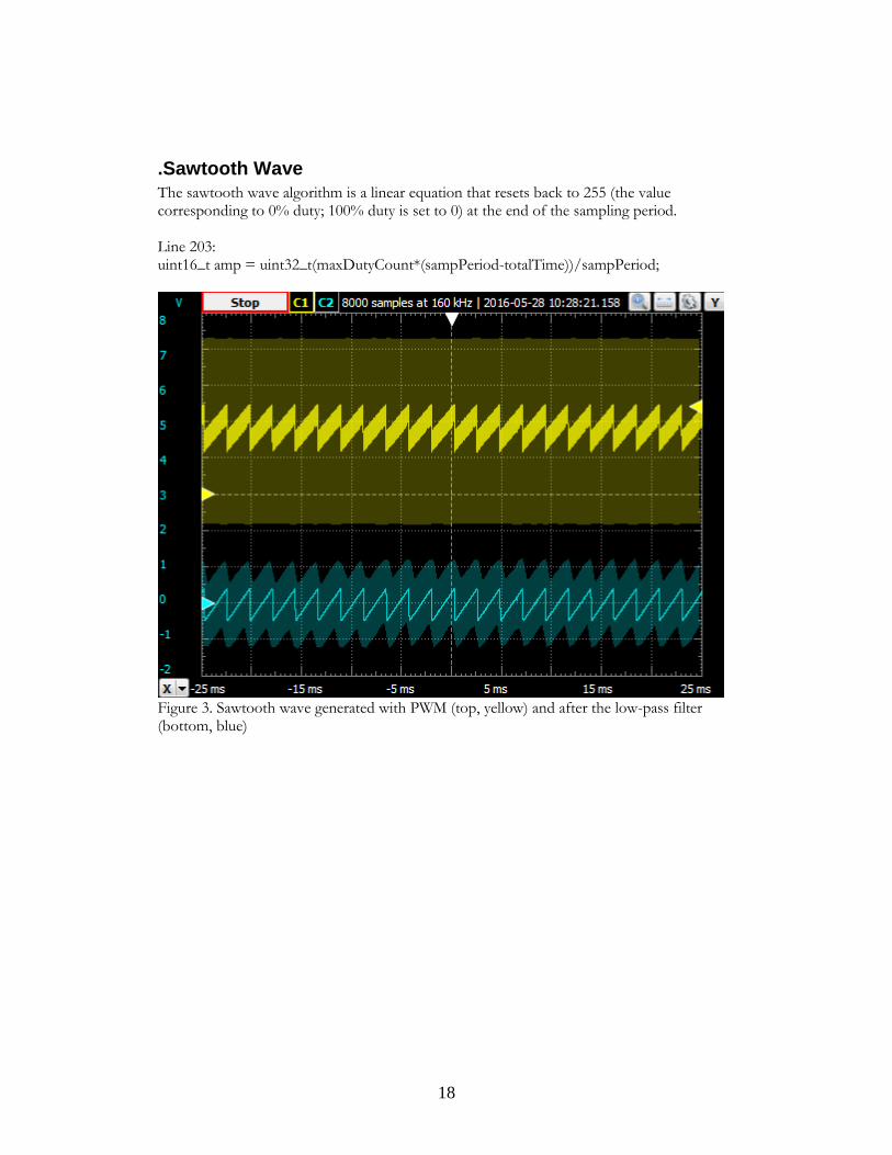
.Sawtooth Wave
The sawtooth wave algorithm is a linear equation that resets back to 255 (the value corresponding to 0% duty; 100% duty is set to 0) at the end of the sampling period. Line 203: uint16_t amp = uint32_t(maxDutyCount*(sampPeriod-totalTime))/sampPeriod;
Figure 3. Sawtooth wave generated with PWM (top, yellow) and after the low-pass filter (bottom, blue)

19
.Triangle Wave
The triangle wave combines the square wave and sawtooth wave algorithms. If it is in the first half of the period, it uses the sawtooth algorithm, and if it is in the second half, it reverses the sawtooth algorithm. Lines 228-234 uint16_t amp = 50; if (totalTime > (sampPeriod>>1)) // if in first half { amp = 2*maxDutyCount*totalTime/sampPeriod-maxDutyCount; } else { // if in second half amp = maxDutyCount-2*maxDutyCount*totalTime/sampPeriod; }
Figure 4. Triangle wave generated with PWM (top, yellow) and after the low-pass filter (bottom, blue)

20
.Sine Wave
To generate a sine tone, I wrote a test program (see Appendix) to generate a table with 9600 values. Since the synthesizer can produce sounds from 20Hz to 5000kHz, the most samples that are needed (for 20Hz) are 9600. The values range from 0 to 255, where 255 indicates a 0% duty cycle, and 0 represents a 100% duty cycle. 222: amp = sineTable[sizeof(sineTable)/(sampPeriod)*totalTime];
Figure 5. Sine wave generated with PWM (top, yellow) and after the low-pass filter (bottom, blue)
.Output Circuit
The synthesizer uses a Sallen-Key 4th Order Butterworth Low Pass Filter as an output, which is a similar circuit to that used in the Nexys 4 FPGA (Digilent, 2013). 1% tolerance resistors and 741 op-amps were chosen to build the circuit. The +/-5V op-amp rails are powered by the Digilent Analog Discovery 2, which was also used as an oscilloscope. The synthesizer can be connected to an amplifier by a standard 35mm audio jack.

21
Figure 6. Schematic for low-pass filter in LT Spice
Figure 7. Simulated frequency response of low-pass filter in LT Spice.
.Code Walkthrough
To handle the MIDI inputs, the MIDI Arduino library was used, as well as example code written by Francois Best and by SparkFun (Best, 2013) (SparkFun Electronics).

22
The first thing the sketch does after declaring libraries is to set up the second serial port, Serial1, to be used for MIDI in line 5. The first serial port, Serial, is used for communication with the console. The PWM is set up in lines 120-141. Next, the MIDI is set up in lines 150-154, calling out two functions: handleNoteOn and handleNoteOff. HandleNoteOn handles the NOTE ON packet when it is received, and creates a linked list of notes. HandleNoteOff handles the NOTE OFF packet when a note is released, and removes the note from the list. It is important that the list is up to date and cleared when necessary, so that so that no notes are lost. For example, if one note “A” is pressed and then a note “B” is also pressed without releasing “A”, “A” will sound, and then “B” will sound instead of “A” when “B” is pressed. If “B” is released and “A” is still being held, “A” will sound again when “B” is released. Since MIDI sends information only when a note is pressed or released (and does not refresh the information), it is important to keep track of which notes have been pressed. Another function, handleNotesChanged (line 63), responds to handleNoteOn and handleNoteOff. If no note is being pressed, handleNotesChanged calls noTone, which triggers the PWM interrupt to begin the ADSR release stage, disabling the PWM. If a note is being pressed, the function reads in the current note, resets the ADSR stage, and calculates the necessary note frequency and sampling period (77-82). Then, the function calls tone (83), which enables the PWM and interrupt. The tone and noTone functions will be discussed in the following section. In the main loop of the sketch, the first function called is MIDI.read (162), which checks on the Serial1 port for a MIDI message, which will then be handled by handleNoteOn or handleNoteOff. Next, the code determines the status of the button that switches the waveform type, which also includes debouncing. The code for the button state is adapted from the Button example sketch that comes with Arduino. Following the code is a table of sine values for the sine calculation.
.Tone and noTone
Tone and noTone are not the default Arduino functions, since these default functions do not compile for the Due. The contents of Tone and noTone were created using the hardware PWM for the purpose of this project. Tone simply enables the PWM and the PWM interrupt, PWM_Handler (263), discussed below. noTone, called when all notes have been released, sets the ADSR switch to the release portion (247-250). The interrupt service routine, PWM_Handler, is laid out on the following page, in Figure 9.

23
Figure 8. Flowchart for PWM_Handler

24
PWM_Handler first forces the test pin high for debugging purposes. The test pin is used to determine the timing of PWM_Handler and to make sure that execution does not take too long. Code that runs too slowly will not run, since the function will be called repeatedly each time the interrupt triggers and it will not finish executing. The interrupt flags are then cleared so that the interrupt occurs only when it should. Reading in the button state, the program selects the waveform to calculate (and calls the appropriate function) using a switch statement (270-286). The code then uses another switch statement to determine the duty cycle of the PWM (corresponding to the amplitude value of the waveform, based on ADSR (290-327). Attack, Decay, and Release are all based on timer values, and Sustain is based on an amplitude value. Attack (291-300) specifies the time in which the waveform goes from no amplitude all the way up to maximum amplitude, and calculates the necessary slope. Decay (301-309) begins when attack has finished and specifies the time in which the waveform goes from maximum amplitude down to the sustain value. Sustain (311-314) holds the wave at a constant amplitude until the key is released. Release (315-327) calculates the slope of the waveform with amplitude decreasing from the sustain value to no amplitude, and then disables the PWM and interrupt. The duty cycle for the ADSR portion is calculated by scaling the ADSR value found above and then dividing by 256 (329-330). The final duty cycle is calculated by adding the duty cycles in the ADSR portion and the waveform calculation together. As a failsafe, lines 333-336 ensure that the value of dutyAct (the final duty cycle) is within the appropriate range. dutyAct is then written to the PWM, and totalTime (where the PWM is within the audio waveform) is calculated by incrementing itself and then a modulo divide is performed by the sampPeriod (calculated in handleNotesChanged based on the necessary note frequency). The test pin is then written low, and the interrupt is ready to be called again to calculate the next value.
.Summary This section reviewed the technical details about how the MIDI synthesizer works, focusing on each subsystem. The PWM interrupt is the heart of the code that generate the audio.
25
Chapter 4 Project Summary
.Overview This section discusses other non-technical aspects of the project, including challenges, how the project relates to coursework, new skills, and time management.
.Project Challenges There were several challenges during the course of this project. The first challenge, on the original schedule that Vicki Depew and I planned, was learning how to program the Digilent Nexys 4 FPGA using Vivado. Both Vicki and I learned HDL using Xilinx’s other program (ISE) and Vivado is very different. Vivado would allow us to do some parts of our project much more easily (such as making a sine tone generator). However, neither she nor I were able to become skilled in using Vivado in a reasonable amount of time. This problem was fixed by changing the scope of the program, and electing to use a microcontroller for the project instead. Another (minor) challenge that I faced was trying to connect the MIDI shield to the Due, since the shield requires 5V and the Due uses 3.3V. This was solved by discussing the problem with Professor Douglas, who suggested that I use logic level shifters to interface the two devices. The most challenging part was getting the PWM interrupt to work correctly. Originally, the tone generator initially used timers, but those proved to be inconsistent, so I decided to utilize the Due’s powerful hardware PWM. The hardware PWM was relatively easy to set up using a test program. After viewing some example code online (SparkFun Electronics), I was able to configure the hardware PWM to output square waves of chosen frequencies (less than the clock frequency of the microcontroller, of course) to a pin, so that I could see the output on an oscilloscope. Looking into the datasheet about the Due’s processor, I could see that there was a way for the PWM itself to affect the timing of the interrupt I added another output pin to my test program that would toggle when the interrupt triggered so that I could test it. Initially, I could not get the interrupt to trigger at all. Professor Douglas and I determined that another subsystem (Nested Vectored Interrupt Controller, or NVIC) in the Atmel processor needed to be initialized to enable the interrupt. However, once the NVIC was configured, the interrupt started interrupting too much, and I only needed it to interrupt once per PWM cycle, at the beginning of the 5.2us period. I poured through the data sheet for a long time, trying to set any registers that might trigger an interrupt (since the interrupt can be configured to trigger during several events in each PWM cycle), but the interrupt triggered the same way, no matter what I did. I eventually figured out that the interrupt was triggering even when the PWM was not, so I knew that the interrupt had nothing to do with the PWM frequency or cycle. Jennifer Guyot, the lab instructor for my Electronics

26
III class, pointed me to the tutoring center, where Loren Lang and I worked together to try to figure out how to configure the interrupt. Luckily, Loren and I were able to make it work. In order to set up the interrupt correctly, the interrupt status register must be read, which tells the Atmel chip that the hardware responds to the interrupt, so I added a few lines of code that do just that. A few more changes to the code set up the interrupt to trigger at the beginning of each 5.2us cycle. Once the interrupt was set up and working, there were a few minor problems with the waveform algorithms that took too long to run in the interrupt, mostly having to do with division (since the Due’s processor does not have a floating point unit). However, once the PWM interrupt problem was solved, the rest of the project was relatively easy in comparison.
.Coursework For this project, I used knowledge gained in many of my classes at OIT. Professor Almy’s microcontroller and digital hardware design courses taught me how to program the hardware and how to work with machine code, since Professor Almy’s microcontroller courses used assembly language. While I did not need to use assembly language for this project, it helped me to understand what was going on inside the hardware, and also how to handle bitwise commands. I also learned how to code a specific piece of hardware using the hardware’s data sheet. In Professor Almy’s HDL classes, I had a project where I had to learn PDP-8 Assembly Language. Since it is an old language specific to the PDP-8 family, there were only a few resources I could rely on to learn the language well enough to program the hardware. From that experience, I figured out how to use the registers in the Atmel chip. Professor Scher’s Digital Signal Processing class, taught me about digital signal processing, which came in handy when I was trying to create different waveform with PWM. In the Circuits and Electronics sequences, I learned about filters and how to design and implement them, which was useful for designing the output filter. My math classes proved especially useful for coming up with algorithms for the various waveforms, especially the general form of a linear equation. I also took the lower-division portion of a computer science program at Portland Community College. Learning C and C++, and also object oriented programming, helped me in this project.
.New Skills I learned several new skills over the course of this project. Before starting this project, I had only made a simple tutorial program using the Arduino Uno with a friend for fun. I really

27
needed to delve into the chip architecture itself for this project, and I had to learn how to read and use the Atmel SAM3x data sheet, as well as look into the CPP and .H files that are compiled into the main Arduino program, since I needed to look up functions to control the PWM.
.Time and Project Management As far as time and project management went, I did not have too many problems once the project started. I had to do about as much work as I was expecting and I was able to pace myself each week for the most part. Once the project was well underway in winter term (when I started working by myself and the scope had changed), I was able to set and meet most of my goals every week. Except for the PWM interrupt problem (discussed above), I feel that I made good progress most weeks. During winter break, since fall term had not been very productive, Vicki and I needed to pick a new piece of hardware and a new plan for the project to continue. Since I was out of the country for most of the break, we had to do it by email. I did not have not have to do much work over spring break, but at that point, I was very stuck on the PWM interrupt problem and progress had stalled and I did not know what to do.
.Summary This section discussed non-technical topics related to the project, including challenges, related coursework, new skills, and time management.

28
Chapter 5 Impact on Career Goals
.Overview This section discusses how the project has affected my career goals and how it will prepare me for success in industry.
.Career Goals Before and After
Before this project started, my career goals were perhaps to go back and work for Intel full-time, possibly in my old group doing microscopy work. However, during the course of my senior year and senior project, I have decided that a technical career is not for me. I am capable of doing the work and I have a good understanding of the concepts involved in electrical engineering and computer science, but I do not believe that I have the personality nor desire to have technical problems being the most important part of my job. I would be much happier working with people. Though I especially enjoy working with technical people, I do not enjoy doing technical work. I become frustrated and stuck easily and cannot move beyond difficult problems. I am much better at divergent thinking, instead of convergent thinking, which is what many technical problems require to solve. I would be more interested in a job in sales, marketing, or management at a technical company where my engineering background would serve me well in helping my employer and potential customers, and leave the building/designing/implementing to somebody who actually enjoys doing it.
.The First Job
Currently, I intend to pursue a PhD in linguistics, focusing on second language acquisition or sociolinguistics, and do not plan to pursue an engineering job. I plan to apply for graduate schools in the fall and then attend in fall 2017. I do not think that it is a good idea to get a real job for a little more than a year, so I have not yet decided what I will do in the meantime except for preparing my application. Perhaps I will go for a short-term assignment, an internship, or a temporary job. Linguistics is sort of my side interest, and I have taken and enjoyed several classes on the subject at Portland State University. In my spare time, I try to learn world languages.

29
.Working in Industry As I have stated above, I do not intend to pursue a technical position. However, I have developed skills that allow me to find resources when I am stuck on things, whether they are people or a manual. I have also become better at reading data sheets and finding programming commands, which would help out if I decided to work in marketing or sales (in order to understand the product and what it can do). I believe my programming skills might also help me out in my linguistics PhD program, as I have been told that many people in the field of linguistics use programming to sort through large sets of data, depending on the subfield.
.Summary
My senior year (among other things) has changed my mind about pursuing a technical career, and I believe I would be much more fulfilled pursuing a non-technical job at a technical company or studying linguistics. World languages are much more interesting to me than computer languages.

30
Chapter 6 Conclusions
.Overview This chapter provides concluding remarks.
.Most Important Things I’ve Learned
In this project, I learned about how to work with the Arduino Due. I also learned about signal processing and how to invent mathematical algorithms.
.Next Time
Since there were a lot of problems at the beginning with the schedule, I would have chosen a simpler project and then added on more features. Since the synthesizer can easily be added on to, adding features and functionality would be possible.
.Continuing the Project This project could be continued by adding on more features to the synthesizer. Right now, the values for ADSR must be hard-coded and compiled. A way to set the values with a button press or potentiometer would make it easier to experiment with sounds. An extra oscillator could be added without too much difficulty. A low-frequency oscillator could add some new sound effects. Since the project was wires on a breadboard, the filter and logic level shifters could be printed on a PCB and an enclosure could be made. Since there are countless effects that can be created with synthesizers, the possibilities are endless.
.Summary
This project is completed.

31
Chapter 7 References Digilent. (2013, September 6). Nexys4 FPGA Board Reference Manual. Retrieved
from Xilinx:
http://www.xilinx.com/support/documentation/university/XUP%20Boards
/XUPNexys4/documenatation/Nexys4_RM_VB1_Final_3.pdf
SparkFun Electronics. (2015, 10 14). MIDI Tutorial. Retrieved from SparkFun.
SparkFun Electronics. (n.d.). MIDI Shield Hookup Guide. Retrieved from
SparkFun: https://learn.sparkfun.com/tutorials/midi-shield-hookup-guide

32
Appendix A: Source Code

[code] 1 #include <MIDI.h> //include library 2 #include "noteList.h" 3 #include "pitches.h" 4 5 MIDI_CREATE_INSTANCE(HardwareSerial, Serial1, MIDI); // use the Serial1 for MIDI 6 7 uint32_t totalTime = 0; // total elapsed time in one waveform 8 9 uint32_t sAudioOutPin = 8; // PWM output pin 10 uint32_t irqPin = 5; // interrupt test pin 11 uint32_t channel = g_APinDescription[sAudioOutPin].ulPWMChannel; // set channel 12 for PWM out 13 uint32_t sampFreq = 192000ul; // sampling frequency (Hz) 14 uint16_t maxDutyCount = 255; // PWM resolution 15 uint32_t clkAFreq = 42000000ul; // clock frequency (Hz) 16 uint32_t pwmFreq = (clkAFreq * 2)/sampFreq; // calculate PWM frequency 17 uint16_t dutyPercent = 128; // starting duty percent 18 uint16_t dutyAct = pwmFreq * (maxDutyCount-dutyPercent) / maxDutyCount; // formula 19 to calculate duty for the processor 20 extern const byte sineTable[9600]; // declare sine table with size 9600 21 22 uint32_t noteFreq = 440; // note frequency, start at middle A 23 uint32_t sampPeriod = sampFreq/noteFreq; // calculate period 24 25 uint16_t ADSRattack = 10000; // attack value in # of PWM cycles 26 uint16_t ADSRdecay = 10000; // decay value in # of PWM cycles 27 uint16_t ADSRsustain = 128; // sustain value in amplitude out of maxDutyCount 28 uint16_t ADSRrelease = 1000; // release value in # of PWM cycles 29 int ADSRtype = 0; // variable to keep track of if we are in attack, decay, etc. 30 uint16_t ADSRtimer = 0; // count number of cycles for ADSR 31 32 static const unsigned sGatePin = 13; 33 //static const unsigned sAudioOutPin = 8; 34 static const unsigned sMaxNumNotes = 16; 35 MidiNoteList<sMaxNumNotes> midiNotes; // keeps track of which notes have been 36 pressed at the same time 37 38 static const uint16_t DEBOUNCE_COUNT = 50; // debounces MIDI input 39 40 //button press for wave select 41 int waveType = 0; // select wave type: 0 sawtooth 1 42 const int buttonPin = 4; // the number of the pushbutton pin 43 const int ledPin = 7; // the number of the LED pin 44 int ledState = HIGH; // the current state of the output pin 45 int buttonState; // the current reading from the input pin 46 int lastButtonState = LOW; // the previous reading from the input pin 47 long lastDebounceTime = 0; // the last time the output pin was toggled 48 long debounceDelay = 50; // the debounce time; increase if the output flickers 49 50 //button press for ADSR select 51 int ADSRsel = 0; // select ADSR values 52 const int ADSRbuttonPin = 5; 53 int ADSRbuttonState; // current state of output pin 54 int ADSRlastButtonState = LOW; // the previous reading from the input pin 55 56 // ----------------------------------------------------------------------------- 57 58 inline void handleGateChanged(bool inGateActive) 59 { 60 digitalWrite(sGatePin, inGateActive ? HIGH : LOW); 61 } 62 63

34
inline void pulseGate() 64 { 65 handleGateChanged(false); 66 delay(1); 67 handleGateChanged(true); 68 } 69 70 // ----------------------------------------------------------------------------- 71 72 void handleNotesChanged(bool isFirstNote = false) 73 { 74 if (midiNotes.empty()) 75 { 76 handleGateChanged(false); 77 noTone();//sAudioOutPin); 78 } 79 else 80 { 81 // Possible playing modes: 82 // Mono Low: use midiNotes.getLow 83 // Mono High: use midiNotes.getHigh 84 // Mono Last: use midiNotes.getLast 85 86 byte currentNote = 0; 87 if (midiNotes.getLast(currentNote)) 88 { 89 ADSRtype = 0; //reset to attack 90 noteFreq = sNotePitches[currentNote+1]; // test frequency 91 sampPeriod = sampFreq/noteFreq; // calculate period 92 tone(); // make a sound! 93 94 if (isFirstNote) 95 { 96 handleGateChanged(true); 97 } 98 else 99 { 100 pulseGate(); // Retrigger envelopes. Remove for legato effect. 101 } 102 } 103 } 104 } 105 106 // ----------------------------------------------------------------------------- 107 108 void handleNoteOn(byte inChannel, byte inNote, byte inVelocity) 109 { 110 const bool firstNote = midiNotes.empty(); 111 midiNotes.add(MidiNote(inNote, inVelocity)); 112 handleNotesChanged(firstNote); 113 } 114 115 void handleNoteOff(byte inChannel, byte inNote, byte inVelocity) 116 { 117 midiNotes.remove(inNote); 118 handleNotesChanged(); 119 } 120 121 // ----------------------------------------------------------------------------- 122 123 void setup() 124 { 125 // put your setup code here, to run once: 126

35
Serial.begin(115200); 127 128 // set up PWM 129 pmc_enable_periph_clk(PWM_INTERFACE_ID); 130 PWMC_ConfigureClocks(clkAFreq, 0, VARIANT_MCK); 131 132 PIO_Configure( 133 g_APinDescription[sAudioOutPin].pPort, 134 g_APinDescription[sAudioOutPin].ulPinType, 135 g_APinDescription[sAudioOutPin].ulPin, 136 g_APinDescription[sAudioOutPin].ulPinConfiguration); 137 138 channel = g_APinDescription[sAudioOutPin].ulPWMChannel; // channel 5 139 PWMC_ConfigureChannel(PWM_INTERFACE, channel, clkAFreq, 0, 0); 140 PWMC_SetPeriod(PWM_INTERFACE, channel, pwmFreq); 141 PWMC_EnableChannel(PWM_INTERFACE, channel); 142 PWMC_SetDutyCycle(PWM_INTERFACE, channel, dutyAct); 143 PWM_INTERFACE->PWM_IER1 = 0x20; //enable interrupt on channel 5 144 PWM_INTERFACE->PWM_IDR1 = 0xFFFFFFDF; //enable interrupt on channel 5 145 PWM_INTERFACE->PWM_IER2 = 0x00002001; //enable interrupt on channel 5 146 PWM_INTERFACE->PWM_IDR2 = 0xFFFFDFFE; //enable interrupt on channel 5 147 148 NVIC_DisableIRQ(PWM_IRQn); // set up interrupt 149 NVIC_ClearPendingIRQ(PWM_IRQn); 150 NVIC_SetPriority(PWM_IRQn, 0); 151 //NVIC_EnableIRQ((IRQn_Type)36); //NVIC_EnableIRQ(PWM_IRQn); 152 //PWMC_EnableChannel(PWM_INTERFACE, channel); 153 //Enable of the Interrupts (writing CHIDx and FCHIDx 154 //in PWM_IER1 register, and writing WRDYE, ENDTXE, 155 //TXBUFE, UNRE, CMPMx and CMPUx in PWM_IER2 register) 156 Serial.println("Test"); 157 158 // set up MIDI 159 pinMode(sGatePin, OUTPUT); 160 //pinMode(sAudioOutPin, OUTPUT); 161 MIDI.setHandleNoteOn(handleNoteOn); 162 MIDI.setHandleNoteOff(handleNoteOff); 163 MIDI.begin(); 164 165 // set up button 166 pinMode(buttonPin, INPUT); 167 } 168 169 void loop() 170 { 171 MIDI.read(); 172 173 // read the state of the switch into a local variable: 174 int reading = digitalRead(buttonPin); 175 176 // check to see if you just pressed the button 177 // (i.e. the input went from LOW to HIGH), and you've waited 178 // long enough since the last press to ignore any noise: 179 180 // If the switch changed, due to noise or pressing: 181 if (reading != lastButtonState) { 182 // reset the debouncing timer 183 lastDebounceTime = millis(); 184 } 185 186 if ((millis() - lastDebounceTime) > debounceDelay) { 187 // whatever the reading is at, it's been there for longer 188 // than the debounce delay, so take it as the actual current state: 189
36
190 // if the button state has changed: 191 if (reading != buttonState) { 192 buttonState = reading; 193 194 // only toggle the LED if the new button state is HIGH 195 if (buttonState == HIGH) { 196 //ledState = !ledState; 197 waveType = (waveType+1)%4; // cycle through various wavetypes 198 } 199 } 200 } 201 202 // save the reading. Next time through the loop, 203 // it'll be the lastButtonState: 204 lastButtonState = reading; 205 206 207 208 // ADSR: read the state of the switch into a local variable: 209 reading = digitalRead(ADSRbuttonPin); 210 211 // check to see if you just pressed the button 212 // (i.e. the input went from LOW to HIGH), and you've waited 213 // long enough since the last press to ignore any noise: 214 215 // If the switch changed, due to noise or pressing: 216 if (reading != ADSRlastButtonState) { 217 // reset the debouncing timer 218 lastDebounceTime = millis(); 219 } 220 221 if ((millis() - lastDebounceTime) > debounceDelay) { 222 // whatever the reading is at, it's been there for longer 223 // than the debounce delay, so take it as the actual current state: 224 225 // if the button state has changed: 226 if (reading != ADSRbuttonState) { 227 ADSRbuttonState = reading; 228 229 // only toggle the LED if the new button state is HIGH 230 if (ADSRbuttonState == HIGH) { 231 //ledState = !ledState; 232 ADSRsel = (ADSRsel+1)%4; // cycle through various wavetypes 233 } 234 } 235 } 236 237 // save the reading. Next time through the loop, 238 // it'll be the lastButtonState: 239 ADSRlastButtonState = reading; 240 241 switch (ADSRsel) { // select wavetype 242 default: 243 case 0: 244 ADSRattack = 10000; // attack value in # of PWM cycle 245 ADSRdecay = 10000; // decay value in # of PWM cycles 246 ADSRsustain = 128; // sustain value in amplitude out of maxDutyCount 247 ADSRrelease = 1000; // release value in # of PWM cycles 248 break; 249 case 1: 250 ADSRattack = 500000; // attack value in # of PWM cycle 251 ADSRdecay = 1000; // decay value in # of PWM cycles 252

37
ADSRsustain = 200; // sustain value in amplitude out of maxDutyCount 253 ADSRrelease = 50000; // release value in # of PWM cycles 254 break; 255 case 2: 256 ADSRattack = 1000; // attack value in # of PWM cycle 257 ADSRdecay = 50000; // decay value in # of PWM cycles 258 ADSRsustain = 100; // sustain value in amplitude out of maxDutyCount 259 ADSRrelease = 2000; // release value in # of PWM cycles 260 break; 261 case 3: 262 ADSRattack = 80000; // attack value in # of PWM cycle 263 ADSRdecay = 4000; // decay value in # of PWM cycles 264 ADSRsustain = 128; // sustain value in amplitude out of maxDutyCount 265 ADSRrelease = 100; // release value in # of PWM cycles 266 break; 267 } 268 } 269 270 271 /* Waveforms */ 272 273 uint16_t sawtooth(void) 274 { 275 uint16_t amp = uint32_t(maxDutyCount*(sampPeriod-totalTime))/sampPeriod; 276 return amp; 277 } 278 279 uint16_t square(void) 280 { 281 uint16_t amp = 128; 282 if ((totalTime%sampPeriod) > (sampPeriod>>1)) // if in first half 283 { 284 amp = 0; // set duty to 100% 285 } else { // if in second half 286 amp = pwmFreq; // set duty to 0% 287 } 288 return amp; 289 } 290 291 uint16_t sineTone(void) 292 { 293 uint16_t amp = 128; 294 amp = sineTable[sizeof(sineTable)/(sampPeriod)*totalTime]; 295 return amp; 296 } 297 298 uint16_t triangle(void) 299 { 300 uint16_t amp = 50; 301 if (totalTime > (sampPeriod>>1)) // if in first half 302 { 303 amp = 2*maxDutyCount*totalTime/sampPeriod-maxDutyCount; 304 } else { // if in second half 305 amp = maxDutyCount-2*maxDutyCount*totalTime/sampPeriod; 306 } 307 return amp; 308 } 309 310 /* Tone */ 311 // frequency (in hertz) and duration (in milliseconds). 312 313 void tone(void) 314 { 315

38
NVIC_EnableIRQ((IRQn_Type)36); //NVIC_EnableIRQ(PWM_IRQn); 316 PWMC_EnableChannel(PWM_INTERFACE, channel); 317 } 318 319 void noTone(void) 320 { 321 ADSRtype = 3; // set type to release 322 ADSRtimer = 0; // reset timer 323 // uint16_t ADSRcalc = 0; 324 // if (ADSRtimer < ADSRrelease) // for duration of release time 325 // { 326 // ADSRcalc = (maxDutyCount-ADSRsustain)/ADSRrelease*ADSRtimer+ADSRsustain; 327 // ADSRtimer++; 328 // } else { 329 //// NVIC_DisableIRQ((IRQn_Type)36); //NVIC_EnableIRQ(PWM_IRQn); 330 //// PWMC_DisableChannel(PWM_INTERFACE, channel); //disable PWM 331 // } 332 } 333 334 //PWM ISR 335 void PWM_Handler(void) // PWM interrupt handler 336 { 337 g_APinDescription[irqPin].pPort -> PIO_SODR = g_APinDescription[irqPin].ulPin; 338 //write pin high 339 340 volatile long dummy = PWM_INTERFACE->PWM_ISR1; // clear interrupt flag 341 dummy = PWM_INTERFACE->PWM_ISR2; // clear interrupt flag 342 343 switch (waveType) { // select wavetype 344 case 0: 345 dutyAct = square(); 346 break; 347 case 1: 348 dutyAct = sawtooth(); 349 break; 350 case 2: 351 dutyAct = triangle(); 352 break; 353 case 3: 354 dutyAct = sineTone(); 355 break; 356 default: 357 dutyAct = sineTone(); 358 break; 359 } 360 361 uint16_t ADSRcalc = 0; 362 363 switch (ADSRtype) { //select ADSR response 364 case 0: // attack 365 if (ADSRtimer < ADSRattack) // for duration of attack time 366 { 367 ADSRcalc = maxDutyCount-maxDutyCount*ADSRtimer/ADSRattack; 368 ADSRtimer++; 369 break; 370 } else { 371 ADSRtype = 1; // set to decay 372 ADSRtimer = 0; //reset ADSRtimer 373 } 374 case 1: // decay 375 if (ADSRtimer < ADSRdecay) 376 { 377 ADSRcalc = ADSRsustain*ADSRtimer/ADSRdecay; 378

39
ADSRtimer++; 379 break; 380 } else { 381 ADSRtype = 2; // set to sustain 382 ADSRtimer = 0; //reset ADSRtimer 383 } 384 case 2: // sustain 385 default: 386 ADSRcalc = maxDutyCount-ADSRsustain; 387 break; 388 case 3: //release 389 if (ADSRtimer < ADSRrelease) // for duration of release time 390 { 391 ADSRcalc = (maxDutyCount-ADSRsustain)/ADSRrelease*ADSRtimer+ADSRsustain; 392 ADSRtimer++; 393 break; 394 } else { 395 ADSRcalc = 0; 396 NVIC_DisableIRQ((IRQn_Type)36); //NVIC_EnableIRQ(PWM_IRQn); 397 PWMC_DisableChannel(PWM_INTERFACE, channel); //disable PWM 398 break; 399 } 400 } 401 402 uint32_t ADSRduty = ((maxDutyCount-ADSRcalc)*dutyAct); 403 dutyAct = ADSRduty>>8; 404 dutyAct = dutyAct + ADSRcalc; 405 406 if (dutyAct > pwmFreq) // safety net 407 { 408 dutyAct = pwmFreq; //dutyAct cannot be more than pwmFreq 409 } 410 411 PWMC_SetDutyCycle(PWM_INTERFACE, channel, dutyAct); //set duty cycle 412 413 totalTime=(totalTime+1)%sampPeriod; 414 415 g_APinDescription[irqPin].pPort -> PIO_CODR = g_APinDescription[irqPin].ulPin; 416 //write pin low 417 } 418 419 420 const byte sineTable[] = {128, 127, 127, 127, 127, 127, 127, 127, 127, 127, 421 //table of sine values 422 423

40
Appendix B: Sine Code #include <math.h>
void setup() {
// put your setup code here, to run once:
Serial.begin(115200);
Serial.println("Test");
Serial.print("{");
double y = 128;
int scaled;
int col;
for(int i = 0; i < 9600; i++)
{
y = sin(2*PI/9600*i);
scaled = -255/2*(y+1)+255;
if(scaled > 255)
{
scaled = 255;
}
else if (scaled < 0)
{
scaled = 0;
}
if ((i % 10) == 0)
{
Serial.println();
}
Serial.print(scaled);
Serial.print(", ");
}
Serial.print("}");
}
void loop() {
// put your main code here, to run repeatedly:
}