mid-section open water measurements using adcps open water mid-section measurements using adcps ......
TRANSCRIPT

qSOP-NA046-01-2015 Open Water Mid-Section measurements using ADCPs
Standard Operating Procedures for Mid-section open water discharge measurements using ADCPs Water Survey of Canada
P Campbell, Water Survey of Canada, Environment Canada, Ottawa, 2015
Version 1.0

1 qSOP-NA046-01-2015 Open Water Mid-Section measurements using ADCPs
Revision History
Version Date Source Description/Rational for Change
1.0 March 2015 PFC
Table of Contents
1 Introduction............................................................................................................ 2
1.1 Note on instrumentation, software and firmware .................................... 5
2 Getting Started with Mid-Section Method Software ....................................... 6
3 Prior to departure: ................................................................................................ 7
4 On arrival at site: .................................................................................................. 8
5 Start measurement: ........................................................................................... 10
6 Data Review ......................................................................................................... 26
Acknowledgements:
This document was written with the assistance of people both within and external to the Water Survey
of Canada. Curt Naumann, Andrew Creighton, Francois Rainville, Alain DuCap, Elizabeth Jamieson, Scott
Hill, Jeff Woodward, Murray Jones, Paul-Emile Bergeron either contributed material, reviewed technical
information or contributed to the development of the mid-section software. Some material was adapted
from previously existing training material created by the USGS Hydroacoustics Working Group (HaWG).
The WSC has benefitted from investigations and recommendations related to mid-section ADCP
measurements originating from the HaWG.

2 qSOP-NA046-01-2015 Open Water Mid-Section measurements using ADCPs
1 Introduction Acoustic Doppler current profilers (ADCPs) are typically used for measuring river discharge from a
floating platform or boat that is continuously moving across the river from one bank to the other. A
hydrographer can also use ADCP’s to measure river discharge using the mid-section method in which the
ADCP is held in place for a specified duration at multiple discrete locations, or verticals1, across the
stream. Water velocity data is captured throughout the depth of flow and averaged to obtain a mean
velocity estimate integrated over the full depth at each vertical. The depth for each vertical is
determined with the ADCP, and representative areas and discharges for each vertical are calculated and
summed to obtain a total discharge.
This document presents guidance and standard operating procedures specific to deploying ADCPs for
open water mid-section measurements. To learn more about WSC Standard operating procedures for
ADCP winter measurements, see qSOP-NA041-2014 Under Ice Discharge Measurements using ADCPs.
1.1 When to do a mid-section ADCP measurement A mid-section ADCP measurement may be a second or third attempt at a discharge measurement that
cannot be completed using the moving boat method. If there is moving bed and the compass is not
functioning as required, alternate ADCP measurement options are mid-section method or stationary
moving bed analysis (SMBA). Figure 1 presents a decision tree diagram to aid the hydrographer in
deciding what type of discharge measurement to carry out for non-wading conditions.
Reasons for using an ADCP in mid-section mode include;
Under- ice measurements
Poor bottom tracking performance combined with poor GPS reception or suspect compass
performance
Difficulty completing moving boat transects
Confirming bank overflow discharges
Check measurements
The mid-section method is not biased by moving-bed conditions because the ADCP is assumed to be held stationary for each measurement location. Bottom tracking is not referenced, only water velocity is measured by the ADCP. This means that moving bed tests are not required as part of a mid-section ADCP measurement.
1 “Verticals” and “panels” are terms used within WSC for the sub-sectioned areas across a stream, each
represented by a water velocity and depth observation at its centre. RiverSurveyor Stationary Live uses “station” to describe the same thing.

3 qSOP-NA046-01-2015 Open Water Mid-Section measurements using ADCPs
Figure 1: Decision tree for discharge measurement options.
(Note: MB = Moving Bed; SMBA = Stationary Moving Bed Analysis)
4 qSOP-NA046-01-2015 Open Water Mid-Section measurements using ADCPs
Some advantages to using the mid-section method for open water hydroacoustic measurements include;
a valid boat speed reference (bottom track or GPS) is not required, eliminating a source of uncertainty
discharge measurement procedures are familiar to hydrographers and
software is available to assist in the procedure. There are also some disadvantages, such as;
a requirement to manually measure positions,
operators need to be careful to account for angled flow (flow not perpendicular to tagline orientation)
the procedure assumes ADCP movement is negligible. Therefore the ADCP must be kept stationary for a valid measurement. 2
1.2 Basic Principles of the ADCP Mid-Section Method Many of the mid-section method standards and procedures defined in the Hydrometric Field Manual-
Measurement of Streamflow (Terzi, 1981) written for mechanical current meters also apply to open
water and under-ice ADCP mid-section measurements. Desirable characteristics of measurement cross
sections for hydroacoustics are the same as a good cross section for a current meter measurement.
These characteristics include:
a measurement section normal or perpendicular to the predominant direction of flow,
a section that has relatively straight and parallel streamlines,
low levels of turbulence (for example, strong eddy lines downstream of bridge piers are not
desirable),
very little to no reverse flows,
regular streambed geometry with few abrupt changes in elevation
A good rule of thumb is to select a measurement location with straight and uniform river banks and bed
for a distance of approximately five times the river width upstream of the section and two times the
width downstream.
The hydrographer must have a method of determining the tagline location of each vertical, referenced
to an initial point on shore and use a deployment platform that will keep the ADCP in a stable position
minimizing rotation/swimming/lateral movements during sampling. A measurement will have a
minimum of 20 verticals (or panels). The locations of each vertical should be distributed such that large
changes in river depths and water velocity are represented. If verticals are correctly located, they
should each represent approximately 5% of total discharge. It is strongly recommended to add an extra
vertical or two where 10% or more of total discharge is represented in a single vertical.
The ADCP provides velocity and depth data for each vertical. The vertical (or panel) width is half the
distance from the current vertical to the previous vertical plus half the distance from the current vertical
2 qSOP NA038-010-2013 Measuring Discharge Using Acoustic Doppler Current Profilers from a moving boat
adapted from USGS Techniques and Methods 3-A22

5 qSOP-NA046-01-2015 Open Water Mid-Section measurements using ADCPs
to the next vertical. Vertical area is vertical width multiplied by the depth measured during the velocity
sampling period. Discharge for each vertical is computed by multiplying the mean water velocity by the
vertical area and incremental discharges are summed to determine the total discharge.
1.3 A note on instrumentation, software and firmware A variety of ADCP types may be used for mid-section measurements, and depending on the
manufacturer, the mid-section discharge measurement software will also vary. Software approved for
under-ice ADCP measurements for WSC operations are SonTek YSI’s RiverSurveyor Stationary Live (RSSL)
and Teledyne RDI’s Section by Section Pro (SxS Pro).
The procedures and guidelines presented in this document are described in the help sections of each of the two primary software packages. Both have detailed, searchable user guides and help functions accessible within the software. Consult them regularly to learn more beyond this document. For a list of the current versions of approved software and firmware, see the Recommended Software and Firmware for Hydroacoustic Instrumentation document (qREC-NA058--201x), found on the WSC intranet Library.

6 qSOP-NA046-01-2015 Open Water Mid-Section measurements using ADCPs
2 Getting Started with Mid-Section Method Software SonTek YSI’s RiverSurveyor Stationary Live (RSSL) and Teledyne RDI’s Section by Section Pro (SxS Pro) are
software that allow ADCP discharge measurements to be run in accordance to mid-section procedures.
NOTE: Information specific to SonTek YSI (SonTek) and Teledyne RDI (TRDI) are identified in separate
boxes. SonTek information is highlighted in grey. Information specific to TRDI is not highlighted.
Both RSSL and SxS Pro software are free, allowing review of existing measurements by anyone with a
personal computer (PC). However some form of registration key is required for RSSL and SxS Pro to
acquire data in mid-section mode.
TRDI: Each ADCP is assigned a unique SxS Pro key to unlock the software for acquiring data. This key
needs to be input into each PC operating SxS Pro Software for that ADCP. Open SxS Pro and select menu
items Help/Register ADCP. The user will be prompted to enter the ADCP serial number and the SxS
software key assigned for that ADCP by TRDI. All WSC RiverRay ADCP’s would have been assigned SxS
Pro keys as standing offer requirement since 2011. It is recommended to display the SxS Pro key clearly
on the exterior of any ADCP if a key exists for that instrument.
SonTek: To acquire data with RSSL software, a key is input into the ADCP firmware using utility software
(SonUtils4). Afterwards any PC with RSSL software will function with the M9/S5 ADCP.

7 qSOP-NA046-01-2015 Open Water Mid-Section measurements using ADCPs
3 Prior to departure: Pre-departure checks and tasks are almost identical to what is done for a moving boat ADCP
measurement. These are described in detail in our standard operating procedures, qSOP-NA038-01-
2013 Measuring Discharge with Acoustic Doppler Current Profilers from a Moving Boat.
The following is a summary of pre-departure tasks.
Inspect ADCP transducer face(s), cables and connectors for damage.
Confirm communication with the ADCP works. For detailed instructions on setting up Sena
Parani SD1000U Bluetooth communications consult qTEC-NA018-01-2013 Recommended WSC
Bluetooth Com Device in the WSC library.
Check that mid-section acquisition software is up to date and the ADCP key code(s) are
recognized:
o For SxS Pro, open the software select from upper menu, configure/ADCP port settings.
Select the COM port number as determined previously (115200 baud, no parity, one
stop bit) then check port by selecting TEST option. It should indicate a good connection
with a green checkmark.
o The listing of the latest firmware and software versions are available in the WSC library
(qREC-NA058201x: Recommended Software and Firmware for Hydroacoustic
Instrumentation)
Assess if the ADCP is suitable for the expected effective depths,
o The TRDI RiverRay typically requires 0.75m depth or more, the SonTek M9 requires at
least 0.4m depth using a screening distance of 16 cm beyond the transducer face.
o StreamPro or S5 are best for consistently shallow depths but like all ADCP’s they can
experience attenuation of signals in cold, clear water. Although a StreamPro may profile
to 6m depths in ideal conditions, in very clear water the range may be limited to less
than 2.5m.
o Be aware that users can switch water modes for ADCPs such as the StreamPro or Rio
Grande to adapt to changing conditions at different verticals within the same
measurement.
Check that batteries or battery packs are fully charged
Ensure the measurement platform is suited for the conditions expected. For example, if
expected water velocities are above 3m/s a standard tethered boat may not be sufficient.
However a high speed tethered boat or remotely operated boat may work better.
Run ADCP system tests. If possible, conduct the test in relatively still water, for example, near
the shore. Some tests require little or no water motion relative to the ADCP and some tests may
fail when not submersed in water.

8 qSOP-NA046-01-2015 Open Water Mid-Section measurements using ADCPs
4 On arrival at site: The selected measurement cross section should have characteristics similar to a good
conventional measurement section.
Look for a measurement section on a location of the river with relatively straight streamlines not significantly influenced by upstream changes in river alignment.
In tethered boat deployments, avoid sections with strong eddy lines/shear layers that may cause rotation and horizontal movement of the ADCP or potentially flip a tethered boat. Tethered boats cannot be controlled where the flow reverses. Sometimes the effects of pier disturbance can be reduced by paying out the tether further downstream but usually it is difficult to obtain a good quality measurement where strong shear effects are visible on the surface.
Do not take unnecessary risks to recover a lost tethered boat. Ensure in advance that contact information is inside the hull or attached to the tethered boat.
A measurement section allowing the hydrographer to be positioned so they can measure the direction of flow relative to the tagline (angle of flow) is preferred but not absolutely necessary. There are methods to measure the angle of flow using the ADCP internal compass but it is preferable to be able to visually estimate/confirm the angle of flow from a position directly upstream or downstream of the ADCP. However do not choose this option if it means selecting a location with significantly more turbulence, strong eddy lines or significant reverse flow.
Check battery voltages and replace if necessary
Obtain an independent water temperature to check against the ADCP measured water temperature.
Don’t forget that mid-section software such as SxS Pro and RSSL have complete help features
integrated into the software. Take the time to learn about it.
If you are using a RiverRay or compass-equipped StreamPro TRDI instrument, this is a good
time to calibrate the compass. Although there is a compass calibration option within SxS
Pro, this will only function for a Rio Grande compass. The ISM compass in a Water Survey
of Canada RiverRay or compass-equipped StreamPro can be calibrated only within
WinRiver II.
Since the compass for a Rio Grande ADCP can be calibrated within SxS Pro, the compass
calibration routine can be done after the initial measurement information is input and the ADCP
test is run. The compass calibration routine in SxS Pro is found under the menu options Tests/
Compass Calibration.

9 qSOP-NA046-01-2015 Open Water Mid-Section measurements using ADCPs
TRDI: Compass calibration (River Ray and compass-equipped StreamPro)
Establish communications between the ADCP and the PC as for a moving boat method either through
radio (i.e. Bluetooth) or direct cable connection for manned boat measurements. For details on
establishing reliable BT communication with RiverRay ADCPs, see qTEC-NA018-01-2013 Recommended
WSC BlueTooth Com Device in the WSC library. Once communication is working within WR II, compass
calibration (accessed through Acquire/Execute Compass Calibration).
Click on the Calibrate button. There is a prompt ”Use Pitch/Roll?” Unless significant pitch and roll is
expected, select No. The “No” or “flat” calibration requires two rotations (one for calibration and one for
verification).
Figure 2: example of compass calibration dialog for flat calibration
The bars will change color as the RiverRay or StreamPro is rotated. Colours indicate the following:
Green(Good), Light Green(Acceptable), Yellow(Within parameters- one or two yellow bars for the entire
rotation is OK) Orange (Unacceptable - Rotate slower), Red(Not measured). The calibration error should
be less than 1 degree. The results will be displayed but will not be recorded within the measurement file
so it is important to record the results after the evaluation in the field notes.
Why are we doing this again? The calibrated compass will be used to account for rotation of the
instrument during velocity sampling periods.
If Pitch/roll is selected, the calibration will require up to eight rotations (four for calibration and four for
verification) while pitching the RiverRay or StreamPro up and down.
After a successful calibration, close WinRiver II and open SxS Pro to start the measurement.

10 qSOP-NA046-01-2015 Open Water Mid-Section measurements using ADCPs
5 Start measurement:
The following are some common elements for starting a new measurement in both SxS Pro and RSSL.
Use WSC folder and file naming conventions.
o The convention for SxS Pro filenames: StationID_YYYYMMDD.sxs.mmt.
(folder can be named Station ID_YYYYMMDD.AQ#)
o The convention for RSSL folder names: (Station ID_YYYYMMDD.SQ#)
ADCP data acquisition parameters :
o Duration: The default sampling period for ADCP mid-section software is 40 seconds.
Depending on the quality of the acquired data the user may be prompted to extend
the sampling period. More details are in the software specific instructions below. If
experience shows that 40 seconds is frequently not enough time to obtain a
minimum 30 valid samples, you may choose to use a 50 second sampling duration.
o ADCP depth: Set the ADCP depth/draft as for a moving boat measurement. If there
is any uncertainty about the ADCP draft, for example, a GPS or radio modem is
removed from the tethered boat, re-measure the draft with a measuring tape.
o Discharge method: The two options for discharge method are mean-section method
and mid-section method. Select mid-section method.
11 qSOP-NA046-01-2015 Open Water Mid-Section measurements using ADCPs
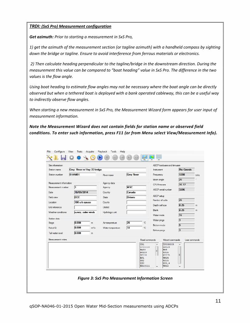
TRDI: (SxS Pro) Measurement configuration
Get azimuth: Prior to starting a measurement in SxS Pro,
1) get the azimuth of the measurement section (or tagline azimuth) with a handheld compass by sighting
down the bridge or tagline. Ensure to avoid interference from ferrous materials or electronics.
2) Then calculate heading perpendicular to the tagline/bridge in the downstream direction. During the
measurement this value can be compared to “boat heading” value in SxS Pro. The difference in the two
values is the flow angle.
Using boat heading to estimate flow angles may not be necessary where the boat angle can be directly
observed but when a tethered boat is deployed with a bank operated cableway, this can be a useful way
to indirectly observe flow angles.
When starting a new measurement in SxS Pro, the Measurement Wizard form appears for user input of
measurement information.
Note the Measurement Wizard does not contain fields for station name or observed field
conditions. To enter such information, press F11 (or from Menu select View/Measurement Info).
Figure 3: SxS Pro Measurement Information Screen

12 qSOP-NA046-01-2015 Open Water Mid-Section measurements using ADCPs
TRDI:cont’d
The rated discharge value can be input at any time during the measurement. This is used to
estimate % discharge per panel, optimizing panel spacing during the measurement and ensuring no
single panel represents more than 10% of total flow at the end of the measurement.
Input the independently observed water temperature.
Once the measurement information form is complete,
Set the ADCP time to the PC time. (see menu option Acquire or Shift-F4)
Run ADCP tests (see menu option Tests/ADCP tests or Shift-F8)
Press ctrl-W (or from Menu select File/New Measurement) to open the New Measurement Form.
Figure 4: Examples of new measurement forms for Rio Grande and RiverRay

13 qSOP-NA046-01-2015 Open Water Mid-Section measurements using ADCPs
TRDI:cont’d
Figure 5: Example of new measurement form for StreamPro
Measurement name: To match WSC file naming convention, select YYYYMMDD date option and
underscore symbol as the delimiter. When the Station ID is typed into the Station number field, it is
automatically set as a name prefix.
Duration: If less than 75% of ensembles are valid at the end of a sampling period, the operator will be
asked if they wish to extend the duration of the data collection period. It is recommended to obtain a
minimum of 30 valid and consistent ensembles at a station/vertical. A 40 second sampling period will
be sufficient for most deployments.
Discharge method: There are two options for discharge method; Mean-section and Mid-section. Select
Mid-section.
Velocity method: There are two ways in which flow directions are referenced in SxS Pro; 1) Magnitude
and 2) Y-velocity. The magnitude method is used in the large majority of open water mid-section
measurements. Magnitude method is used when the ADCP is free to rotate with the changing angle
of flow (i.e. a tethered boat deployment with a single point of attachment). The Y-velocity method
measures the horizontal water velocity parallel to beam 3 and is used in under-ice measurements
or when the transducer orientation is fixed (i.e. no rotation with respect to the measurement
section). Magnitude velocity method is usually used for open water measurements but if y-velocity
is used for a fixed-orientation platform, the user should be aware that the TRDI convention for SxS
Pro is to hold beam 3 downstream (perpendicular to tagline, facing downstream to be more
precise).In this case, it may be necessary to use a beam 3 misalignment factor of 180, 240 or 320
degrees to re-orientate beam 3 so it is facing in the predominant downstream direction.

14 qSOP-NA046-01-2015 Open Water Mid-Section measurements using ADCPs
TRDI:cont’d
If a velocity method other than magnitude is used for an open water measurement, justify the
reason in the comments section and also in the field notes.
For the Rio Grande and Stream Pro it is recommended to input maximum water depth and
maximum water speed but it is not recommended to complete the secondary depth field for the Rio
Grande form. Instead, at changes of water depth and/or velocity, the user should stop pinging
change the depth/velocity settings and restart pinging. Use the auto water mode setting.
After completing the new measurement form/ Measurement Wizard form, address any warnings in the
text box at the bottom and correct as necessary.
The software prompts the user for information about the starting edge of the water. SxS Pro labels the
starting edge as Vertical 1.
Select right or left bank starting edge as per convention (looking D/S), input the distance from IP to the
edge of water. In many cases, distance from IP may be zero. If there is a vertical wall at the starting
edge, the depth at edge must be input at this time as well as a velocity correction factor. The default
velocity correction factor is 0.00 for SxS Pro. A measured vertical would be at a distance approximately
equal to the depth at the wall and in this case a typical correction factor for the velocity at the wall or
pier with a smooth surface is 0.65. This correction factor would be reduced with increasing wall/pier
roughness. (VALIDATE coefficient with reference)
Fig 6 – Input initial edge information (SxS Pro)
Once the starting edge information is complete and the user selects “OK”, commands are sent to the
ADCP. The ADCP is pinging but not yet recording, providing depth and quality of signal information.
Before hitting the “Next” vertical button (or F5 start recording) choose a location for vertical 2 with at
least 2 good depth cells. Monitor the intensity profile for irregular spikes in one or more beams at varying
depth potentially indicating static objects like submerged branches. If contamination from static objects
is suspected, change the location of the vertical.

15 qSOP-NA046-01-2015 Open Water Mid-Section measurements using ADCPs
TRDI:cont’d
Figure 7 -Example of Intensity Profile in SxS Pro without beam obstructions
Figure 8 - Example of SNR profile with beam obstruction (RSSL)
When the location for vertical 2 looks suitable, push F5 or the “Next” button. This will be the first vertical
with a measurable water velocity. Each vertical form has space for notes specific to that vertical. Notes
can be input prior to recording. To insert a note on a previously recorded vertical, double click on that
vertical.
Figure 9 – Vertical detail form

16 qSOP-NA046-01-2015 Open Water Mid-Section measurements using ADCPs
TRDI:cont’d
Input the tagline position as distance from IP and select the velocity profile type. The Water tracking
error velocity is a function of the previously input maximum depths/velocity values (for Rio Grande and
StreamPro).
Flow angle: If the hydrographer is in a good position to directly measure the angle of flow now is a good
time to measure and input the angle. Flow angle can be input as either 1) angle in degrees from the
expected perpendicular from tagline or 2) coefficient such as 0.99 based on the cosine.
After inputting a flow angle correction or coefficient value, check to ensure it is not inadvertently
repeated in subsequent verticals. This has been a reported issue within SxS Pro.
Water Depth Source: The default method to determine depth at the current vertical is by Bottom Track,
which is the average depth measured by the 4 beams. Other options include vertical beam and
composite for instruments equipped with vertical beams. The composite depth method will use the
vertical beam if it is generating acceptable data and use bottom track otherwise. It is recommended to
use the default setting of composite depth for ADCPs equipped with vertical beams.
If the ADCP is having issues detecting the bottom, use manual depth by sounding with a wading rod,
survey rod, weighted line, or some other method. Intermittent valid pings from SxS Pro might also be
used. Once the manual depth has been measured, select manual depth as the source and enter the
value. There are many cases where the ADCP can’t measure a depth, but with a manual depth, can still
measure a valid water profile.
At any time, a processing form can be viewed by hitting F3.
If there are less than five bins at a vertical, the user should consider changing the max depth setting in
the Measurement Wizard (this is not applicable to RiverRay deployments where the bin sizes are
automatically selected). To do this, stop pinging (F4), open the measurement wizard (F2) and change the
max depth setting. It is not advisable to change the configuration at every vertical but this setting
can be changed on occasions where depths and/or velocities change significantly. Selecting smaller
bin sizes will introduce greater noise in bin velocities. You might try fewer and larger bins when the
velocities appear too noisy.
Figure 10 – Processing interface for SxS Pro

17 qSOP-NA046-01-2015 Open Water Mid-Section measurements using ADCPs
TRDI:cont’d
The default setting for minimum number of good ensembles for a cell is 1. This means that if only
one velocity sample over 40 seconds is available for a given cell depth, this cell will still be used in
the determination of the average water velocity for the vertical. This can be adjusted in post
processing to get rid of anomalous velocities.
The default setting for 3 beam solution for water tracking (WT) is off. If there is suspected
interference with one of the 4 beams (for example vertical walls), turn on 3 beam solution to see if
there is an improvement.
Check thermistor: If the ADCP measured temperature is not within 2 degrees of the independent
temperature, wait until the ADCP thermistor stabilizes to within this range. If there is a suspected broken
thermistor, override the ADCP temperatures with a manually input value, noting the discrepancy in the
measurement field notes. Tag the ADCP for suspected faulty thermistor and have the ADCP thermistor
checked by the manufacturer.
As with moving boat measurements a minimum of 2 depth cells must be obtained at every vertical.
Figure 11 - SxS Pro acquire view with red circle (<2 good depths cells),yellow circle ( 2 good depth
cells)and green circle (>2 good depth cells)
Once the station (vertical) is complete, a Measurement Results dialog shows a summary of the station
for review and prompts to Accept to proceed to the next station or Reject to measure the same station
again. Continue this process for the entire cross section. If a station is inadvertently accepted, it cannot
be deleted but instead it can be “unselected” at any time so it will not be used in the final measurement
results. This capability applies to both SxS Pro and RSSL. To “unselect” a desired vertical simply navigate
to the discharge summary page and “unselect/uncheck” a vertical in SxS Pro this is done within the
vertical/details selection view, accessed through F12 or select view/vertical details selection from the
main menu.
Inserting stations/verticals: If necessary, a station/vertical can be inserted at any time during the
measurement. Neither SxS Pro nor RSSL will allow two active stations/verticals at the same location. SxS
Pro allows replacing one station with another station at the same location, keeping only one active.
If velocity data cannot be obtained, a manual vertical can be inserted (F8). A manual vertical requires
user input for depth and water velocity which may be estimated or obtained from another instrument
such as a FlowTracker.

18 qSOP-NA046-01-2015 Open Water Mid-Section measurements using ADCPs
TRDI:cont’d
SxS Pro uses manual verticals for islands/piers. A pier can be represented clearly by using manual
verticals in the following way. If the width of the pier is relatively narrow compared to the panel widths,
set a panel on either side of the pier equal to ½ the pier’s width. For instance if you are collecting at 10m
intervals and there is a 4m wide pier, set a measurement at 2m from either edge of the pier. If it is not
deep enough at these locations, you can make a manual estimate of velocity at those locations. Set a
manual measurement at the centerline of the pier with a depth of 0.00m and a velocity of 0.00m/s.
There should be a clear representation of the pier in the contour plot.
Users can temporarily abort a partially completed measurement and continue the measurement at a
later time.
Press<F6> to end the measurement. The following dialog box opens
.
Figure 12: End measurement form

19 qSOP-NA046-01-2015 Open Water Mid-Section measurements using ADCPs
SonTek: (RSSL)
When creating a new measurement in SonTek RiverSurveyor Stationary Live, connect to the ADCP by
clicking on the connection command or Cntl+N shortcut. Select the appropriate COM port number, if
unsure which COM port checking under Control Panel/Device Manager/Ports (COM &LPT).
Figure 13: RSSL Initial connection to ADCP
Once connected, the Start Page appears (Figure 14).There is an option to retrieve a station template. A
station template contains the ADCP measurement location information (i.e. tagline location of start/end
edges and all panels, transducer depth at each panel etc.) typically saved from a previous measurement
at the same site. Site information such as the station name and ID can also be saved and retrieved for
future measurements. If no site information file is available, the site information can be easily input
manually. The start page directs users to follow many of the necessary steps prior to starting a
measurement.
Set the time from the PC/tablet.
Run a beam check and confirm there are no unusual artifacts or separation of beams at the
different frequency options. An example of an expected beam check result for the 3MHz
transducers is shown in Figure 15.
Run System tests.

20 qSOP-NA046-01-2015 Open Water Mid-Section measurements using ADCPs
SonTek: (cont’d)
Figure 14 – RSSL Start Page
Figure 15 – RSSL Beam Check test

21 qSOP-NA046-01-2015 Open Water Mid-Section measurements using ADCPs
SonTek: (cont’d)
For under ice measurements the M9/S5 is deployed using XYZ (or instrument reference) for
orientation but for open water RSSL deployments, the ADCP is usually free to rotate with the
changing flow angles. To account for these changes in orientation, the M9/S5 compass is
calibrated, the tagline azimuth is determined and ENU (or earth) reference is used.
Figure 16 – Example of RSSL Compass Calibration output (RSSL version 2.6)
Figure 17 – Example of RSSL Compass Calibration output (RSSL version 3.8)
Review compass calibration instructions in the software documentation prior to calibrating the
compass.

22 qSOP-NA046-01-2015 Open Water Mid-Section measurements using ADCPs
SonTek: (cont’d)
Calibrate the compass at a location representative of the magnetic environment at the
measurement section. For example, do not calibrate the compass next to bridge wing-wall
containing rebar and attempt to measure several meters downstream of the bridge. Ensure no
electronics or ferrous materials are near the instrument during calibration. Vary the pitch and roll
enough during the calibration to cover the expected range the ADCP will experience during the
measurement and induce pitch and roll slowly during calibration. Note that calibration criteria for
the G3 compass (firmware and software versions 3.8 and later) are different than previous versions
of RSSL and RSL. The recommended passing compass calibration error is 0.5 degrees or less.
Water Survey of Canada had placed restrictions on the use of the M9/S5 using a compass not yet
upgraded to version G3 compass (2014 or later using version 3.8 firmware and software). All
versions of the M9/S5 compass can be used for open water mid-section deployment provided the
user closely monitors the orientation of the ADCP during acquisition for flow directions inconsistent
with observed conditions. In the interim, it is recommended that all M9s and S5s be upgraded to
the G3 compass.
After calibrating the compass, set the tagline azimuth. To do this you can select “change system
settings” command/get tagline azimuth then follow the software instructions. The tagline azimuth
value is obtained by setting the ADCP in the flow typically near the center of the river where the
streamlines are likely parallel to the riverbanks. The tagline azimuth value will automatically
update after running the azimuth routine. This routine assumes that the tagline is perpendicular to
flow, which is often the case but in cases where tethered boats are deployed from a bridge that is
not perpendicular to flow, obtain an independent value of tagline azimuth with a hand held
compass and input that value. This should also be validated against the ADCP compass by
comparing the measured instrument heading to an observed heading from a handheld compass.
Figure 18 – Steps to obtain tagline Azimuth using M9/S5 compass

23 qSOP-NA046-01-2015 Open Water Mid-Section measurements using ADCPs
SonTek: (cont’d)
Other recommended system settings are; “System” for track reference, “Vertical Beam” for depth
reference, Mid-Section for discharge method and Smart Pulse enabled.
Figure 19: RSSL Start Edge form
Once Start Measurement is selected, there is a prompt for starting edge information. RSSL prompts for
starting bank (left or right), distance from an Initial point to the water’s edge, edge depth and velocity
correction factor. The velocity correction factor allows the user to input an estimated water velocity at an
edge section as a percentage of the closest measured velocity. The default velocity correction factor is
1.00 for RSSL. When a starting or terminating edge is a vertical wall, the nearest measured station would
be at a distance approximately equal to the depth at the wall. In this case a typical correction factor for
the velocity at the wall or pier with a smooth surface is 0.65. This correction factor would be reduced
with increasing wall/pier roughness. (VALIDATE coefficient with reference)
If the ADCP measured temperature is not within 2 degrees of the independent temperature, wait until
the ADCP thermistor stabilizes to within this range. If there is a suspected broken thermistor, override
the ADCP temperatures with a manually input value, noting the discrepancy in the field notes. Tag the
ADCP for suspected faulty thermistor and have the ADCP thermistor checked.
RSSL labels the starting edge as Station 1. Users will be prompted to input the water surface type, open
water in this case, after inputting the starting bank information.

24 qSOP-NA046-01-2015 Open Water Mid-Section measurements using ADCPs
SonTek: (cont’d)
When edge information is complete, go to the first vertical beyond the edge of water.
In RSSL, once the edge (Station 1) is complete and you have moved the instrument to the first
measurement location (Station 2), the station dialog opens, the instrument starts pinging and you can
monitor the SNR (signal to noise ratio) profile plot for obstructions on individual beams.
Set Screening Distance: transducer depth from water surface + 0.16m Coordinate System: ENU
Water Surface Type select “Open Water”.
Figure 20 – Station details within RSSL
Press the Measure button to begin collecting data, Cancel to go back to review the measured station information, or End Edge to input the end edge location information. If you had pressed Cancel and now wish to proceed with the measurement, look for the Next Station (F5) on raw sample display form. As with moving boat measurements a minimum of 2 depth cells must be obtained at every vertical to
ensure the velocity profile is more accurately represented.

25 qSOP-NA046-01-2015 Open Water Mid-Section measurements using ADCPs
SonTek: (cont’d)
If water velocities can be measured but an accurate depth cannot be obtained due to weeds or high
suspended sediment concentrations, RSSL has an option to manually input depths at a vertical/station.
This depth value might be obtained by manual sounding or observing intermittent valid depths while
pinging.
Be aware of obstructions within the water column by monitoring the SNR levels. During data acquisition, monitor the following:
profile plots for beam blockage(see figure 8). contour plots for obvious input errors in depths.
Inserting stations/verticals: If necessary, a station/vertical can be inserted at any time during the measurement. Neither SxS Pro nor RSSL will allow two active stations/verticals at the same location. Temporarily Interrupting a measurement: If it is necessary to temporarily stop collecting data, shut down the software or change instruments prior to ending the measurement, the measurement can be reopened and restarted at a later time as long as end measurement/end transect was not confirmed. When a user reopens a measurement without an ending edge they will be prompted to either end the measurement or continue with data collection. Islands or Piers Edges are handled in RSSL through the Island Edge box at the bottom of the station dialog window. The user will be prompted for all information once selecting this option. End Edge to input the ending edge location. Beware that once the measurement has ended you will not be allowed to insert any additional stations/verticals. If a station/vertical has more than 5% of the flow, now is time to insert the extra panel prior to selecting End Edge. Finally you will be prompted to end the measurement. Press the End Transect button to complete the measurement.

26 qSOP-NA046-01-2015 Open Water Mid-Section measurements using ADCPs
6 Data Review Data must be thoroughly reviewed while still on site to identify and correct any potential acquisition error. Use the Hydrometric survey notes to conduct a thorough field review. Among the listed items within the survey note, check:
Diagnostic test results OK and logged.
ADCP clock set.
Temperature sensor valid
Review contour plot as a visual check on input errors for ADCP draft, water depths widths of verticals etc.
Suitable number of panels and % of discharge per panel not excessive
Look at flow vectors/flow direction to detect obvious inconsistencies or errors.
Minimum number of valid number of ensembles and sampling duration achieved
(SxS Pro only) Are there several missing cells within station/vertical? If so, check to see if there are enough bins measured to allow reasonable extrapolations at the top and bottom. In clear water, there may be several missing bins. This is displayed as intensity and correlation profiles drop to noise floor level and staying at those levels (60 counts or lower for RiverRays, 85 or lower for StreamPro) It may be necessary to increase sampling times at each panel, increase the size of the bins or change the water mode. Another possible solution to increase the range of the StreamPro is to increase the supply voltage. The StreamPro will handle up to 19VDC. WSC offices are investigating options to boost voltage to 18v.
SNR/intensity. Look for spikes caused by obstructions.
Click on individual stations/verticals to view extrapolated portions of profiles Do the top and bottom extrapolations look like reasonable extensions of the measured portions or are there discontinuities between the measured and estimated portions? You may need to adjust the exponents (to do this, see explanation below). In most cases, extrapolation settings are consistent among stations/verticals.
The typical extrapolation method for open water is 1/6th power law. If there are strong wind effects or bidirectional flow, the upper extrapolation methods can be changed to constant and no slip in RSSL or constant and 3 point in SxS Pro. Operators should obtain previous extrapolation settings used in the application of the USGS EXTRAP program for moving boat measurements at that site as a point of reference for setting extrapolation settings in mid-section measurements. The exponent can be changed from the default 1/6 value to another by accessing the processing form (F3). These alternate top profile extrapolations are a reflection of the site conditions observed by the hydrographer at the time of the measurement.
SonTek: To edit extrapolation settings (or other profile information like depths/offsets or reference system) double click on any station within the contour plot or select Edit Station within the samples tab view. There is a Profile Extrapolation button in the bottom left corner of the dialogue to make changes. The station details form will appear. If applying a change to all profiles don’t forget to check “Apply to All”. A commonly seen problem with recent versions of RSSL is an apparent insensitivity to adjusting the number of cells or % of vertical for the application of the top extrapolation.

27 qSOP-NA046-01-2015 Open Water Mid-Section measurements using ADCPs
TRDI: In SxS Pro, it is important to visually review the top and bottom extrapolations. Check the contour plot for consistent velocity profiles, flow directions and effective depths between verticals. The tabular view is also very helpful for checking consistency in data such as large changes in flow directions between verticals as well as detecting input errors. To change the extrapolation settings, hit F3 for the processing form. And change the power exponent value. This value applies to all verticals not individual verticals. Do not spend time trying to optimize the extrapolation for every vertical. Instead choose the extrapolation method and exponent that fits best with the most verticals. You may check to see how sensitive the final discharge is to changes in extrapolation settings. Changing exponents often result in insignificant changes to final discharge.
When on site review is finished, lock measurement.
Backup the measurement file to a USB key

28 qSOP-NA046-01-2015 Open Water Mid-Section measurements using ADCPs
Appendix A – Shortcuts/Quick keys
Section by Section Pro Shortcuts KEY Description
F1 Help
F2 Configure Measurement Wizard
F3 Configure Processing Parameters
F4 Start/Stop Pinging
F5 Start/Stop collecting verticals data
F6 Create Start/End edge
F7 Configure (edit) current vertical
F8 Toggle left or right bank
F11 Toggle Measurement Info view
F12 Toggle Verticals Details/Selection view
Ctrl + C Copy table when in verticals details/selection view
Ctrl + E Close measurement file
Ctrl + L Lock/Unlock measurement file
Ctrl + O Open measurement file
Ctrl + S Save measurement file
Ctrl + W Create new measurement file
Ctrl + M View Summary XML file
Ctrl + E View Summary CVS
Ctrl + A View Summary ASCII file
Shift + F4 Set ADCP clock
Shift + F8 Execute or view ADCP tests
Shift + F9 Execute or view compass calibration
Ctrl + ← Move to the previous vertical
Ctrl + → Move to the next vertical
RiverSurveyor Stationary Live Shortcuts (partial list) KEY Description
Ctrl + O Select stationary measurement file to open
Ctrl + T Toggle Processing tools menu options
Ctrl + N Connect to ADCP
Ctrl + N
Page up/down Toggle through view tabs (System/Samples/Time series/Transect)
Arrow up/left Toggle back through stations
Arrow down /right Toggle forward through stations

29 qSOP-NA046-01-2015 Open Water Mid-Section measurements using ADCPs
Appendix B Example of Hydrometric Survey Notes for
Mid-Section method
For complete copies of the survey notes, see WSC Library;

30 qSOP-NA046-01-2015 Open Water Mid-Section measurements using ADCPs

31 qSOP-NA046-01-2015 Open Water Mid-Section measurements using ADCPs

32 qSOP-NA046-01-2015 Open Water Mid-Section measurements using ADCPs