microwave oven installation instructionsmanuals.electroluxusa.com/prodinfo_pdf/springfield/... ·...
TRANSCRIPT

MICROWAVE OVEN INSTALLATION INSTRUCTIONS
INSTALLATION AND SERVICE MUST BE PERFORMED BY A QUALIFIED INSTALLER.IMPORTANT: SAVE FOR LOCAL ELECTRICAL INSPECTOR'S USE.
READ AND SAVE THESE INSTRUCTIONS FOR FUTURE REFERENCE.
The electrical requirements for this oven are 115-120 volts AC, 15 amps or larger.
IMpORTANT - pLEASE REAd ANd FOLLOWBefore beginning, please read these instructions completely and carefully.•
Be sure to DISCONNECT THE PLUG of the microwave oven from the electrical outlet before installing the built-in trim kit. •Remove the turntable from the oven cavity.
Because the kit includes metal parts, caution should be used in handling and installation to avoid the possibility of injury.•
Do not remove permanently affixed labels, warnings, or plates from the product. This may void the warranty.•
Please observe all local and national codes and ordinances.•
The installer should leave these instructions with the consumer who should retain for local inspector’s use and for •future reference.
pARTS INCLUdEd IN THE KITS 1) FRONT FRamE aSSEmBLy
QTy 12) BOTTOm DUCT aSSEmBLy
QTy 1
3) SCREw a (1 3/16" LENGTH) QTy 2
4) SCREw B (1 3/4" LENGTH) QTy 4
MICROWAVE OVEN INSTALLATION INSTRUCTIONS

E2
MICROWAVE OVEN INSTALLATION INSTRUCTIONSBASIC SPECIFICATIONS
Refer to Illustration 1. all dimensions are in inches (cm).
Illustration 1
Provide an opening in the wall or cabinet as indicated 1. in Illustration 1. The depth should be a minimum of 20" (50.8 cm). The floor of the opening should be constructed of plywood strong enough to support the weight of the microwave oven (about 100 lbs.) and should be level for proper operation of the oven.
NOTE: while the proper functioning of the microwave oven does not require that the opening be enclosed (with sides, ceiling and rear partition), this may be
required by local code, and it is suggested that the local code be checked for any such requirement.
Outlet should NOT be in the shaded area as indicated 2. on Illustration 1. at the rear of the opening, provide a 3-pronged, polarized, electrical outlet, 115-120 volt aC, 15 amp or larger.
minimum required distance between the microwave 3. oven and the wall oven should be 2-inches of visible cabinet showing after installation.
PRODUCT DIMENSIONS
EI30M045T TRIM KIT
A B C D E F G
30" (76.2 cm) 18 1/16" (45.9 cm) 2 5/16" (5.9 cm) 24" (60.96 cm) 13 3/8" (33.9 cm) 17 3/4" (45.1 cm) min. 30" (76.2 cm)
EI27M045T TRIM KIT
A B C D E F G
27" (68.6 cm) 18 1/16" (45.9 cm) 2 5/16" (5.9 cm) 24" (60.96 cm) 13 3/8" (33.9 cm) 17 3/4" (45.1 cm) min. 27" (68.6 cm)
CUTOUT DIMENSIONSmin. H max. min. I max. J
25 1/4" (64.14 cm) 25 3/8" (64.5 cm) 16 1/4" (41.3 cm) 16 3/8" (41.6 cm) min. 20" (50.8 cm)
BASIC SPECIFICATIONS
OVEN INTERIOR ELECTRICaL REQUIREmENTS
aPPROxImaTE SHIPPING wT. max amP. USaGE
wIDTH HEIGHT DEPTH OVERaLL120VaC/60 Hz (UL)120VaC/60 Hz (CSa) 46 lbs. (20.9 kg) 1.5 Kw 13.0 amps (UL)
1.50 Kw 13 (CSa)17 3/8" (44.1 cm) 10 1/2" (26.6 cm) 18 5/8" (47.3 cm) 2.0 cu. ft.
AD
C
E
F
G
I
J
H
B
6" (15.2 cm)
4" (10.2 cm)
4" (10.2 cm)
installation over an electric walloven 2" (5.1 cm) minimum gap
Product overlap7/8" (2.2 cm)

Illustration 1
E3
MICROWAVE OVEN INSTALLATION INSTRUCTIONS
BOTTOM dUCT ASSEMBLY1. Place the bottom duct in the opening and center. when
the Bottom Duct assembly is in the opening correctly, the flange will be tight against the lower edge of the opening. See Illustration 2.
Illustration 2 Illustration 3
Illustration 4 Illustration 5
SCREw aSCREw a
2. Secure the Bottom Duct assembly with the two (1 3/16") screws a. IMPORTANT: Secure screws to the inside cabinet. See Illustration 3.
UNIT INSTALLATION1. Place the oven adjacent to the wall or cabinet opening.
Plug the power cord into the electrical outlet. Carefully guide the oven into the prepared opening. Slide the oven on the Bottom Duct assembly. avoid pinching the cord between the oven and the wall. adjust the position of the oven so that it will rest on the Bottom Duct assembly, but not fully pushed in. See Illustration 4.
2. Locate tabs on the built in trim kit to the slots on control panel. Snap the built in trim kit into the control panel to lock in place. See Illustration 5.
SHaPE ON BOTTOm

MICROWAVE OVEN INSTALLATION INSTRUCTIONS
3. Push the position of the oven into the cabinet so that the feet of the oven are fitted into the recesses of the Bottom Duct assembly. make sure that the kit now rests flush with the cabinet. See Illustration 6.
Illustration 6
Illustration 7
SCREw B
SCREw B
SCREw B
SCREw B
4. adjust the frame so that the gap around the top of the door and frame is even. Pre-drill 4 holes using an ¹⁄₈" bit, using the kit to guide the holes. attach the built-in trim kit frame with four screws B to the cabinet. See Illustration 7.
IMPORTANT: Install top left mounting screw first in order to secure proper alignment of frame to oven face.
TINS-B003mRR1

F1
dIRECTIVES d’INSTALLATION dU FOUR À MICRO-ONdES
UN INSTALLATEUR QUALIFIÉ dOIT pROCÉdER À L’INSTALLATION ET AUX RÉpARATIONS.IMpORTANT : CONSERVER À L’USAGE d’UN INSpECTEUR EN ÉLECTRICITÉ LOCAL.
LIRE ET CONSERVER CES dIRECTIVES pOUR RÉFÉRENCE FUTURE.
AVERTISSEMENT L’alimentation électrique pour ce four est de 115-120 volts CA, 15 ampères et plus.
IMpORTANT - pRIÈRE dE LIRE ET dE SUIVRE• Prièredelireattentivementtoutescesdirectivesavantdecommencer.
• VeilleràDÉBRANCHERLAFICHEdufouràmicro-ondesdelapriseélectriqueavantd’installerlagarnitureàencastrer.Retirerlatabletournantedelacavitédufour.
• Lekitcomprenddespartiesmétalliques,ilfautfaireattentionlorsdelamanipulationetdel’installationpouréviteréventuellesblessures.
• Nepasretirerdefaçonpermanentelesétiquettes,lesmisesengardeoulesplaquesfixéesauproduit.Celapourraitannulerlagarantie.
• Veuillezobservertouslescodesetrèglementslocauxetnational.
• L’installateur devra laisser ces directives au client qui devra les conserver pour l’usage d’un inspecteur local et pour référence ultérieure.
pIÈCES FOURNIES AVEC LES KITS 1) ENSEmBLE DU CHâSSIS aVaNT
QTÉ12)ENsEmBLEDuCoNDuITINFÉRIEuR
QTÉ1
3) VIS a (LONGUEUR 1 ³₁₆ po)QTÉ2
4) VIS B (LONGUEUR 1 ³₄ po)QTÉ4
F2
dIRECTIVES d’INSTALLATION dU FOUR À MICRO-ONdES BASIC SPECIFICATIONS
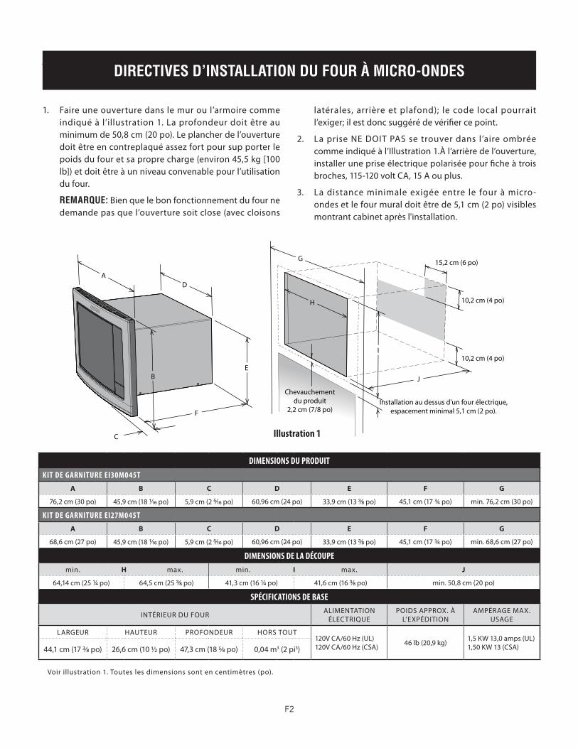
Voirillustration1.Touteslesdimensionssontencentimètres(po).
Illustration 1
Faireuneouverturedanslemuroul’armoirecomme1. indiquéàl’illustration1.Laprofondeurdoitêtreauminimumde50,8cm(20po).Leplancherdel’ouverturedoitêtreencontreplaquéassezfortpoursupporterlepoids du four et sa propre charge (environ 45,5 kg [100 lb])etdoitêtreàunniveauconvenablepourl’utilisationdu four.
REMARQUE: Bien que le bon fonctionnement du four ne demandepasquel’ouverturesoitclose(aveccloisons
latérales,arrièreetplafond); lecode localpourraitl’exiger;ilestdoncsuggérédevérifiercepoint.
La prise NE2. DOIT PAssetrouverdans l ’aireombréecommeindiquéàl’Illustration1.Àl’arrièredel’ouverture,installerunepriseélectriquepolariséepourficheàtroisbroches, 115-120 volt Ca, 15 a ou plus.
Ladistanceminimaleexigéeentre le fouràmicro-3. ondesetlefourmuraldoitêtrede5,1cm(2po)visiblesmontrantcabinetaprèsl'installation.
DIMENSIONS DU PRODUIT
KIT DE gARNITURE EI30M045T
A B C D E F G
76,2 cm (30 po) 45,9 cm (18 ¹₁₆ po) 5,9 cm (2 ⁵₁₆ po) 60,96 cm (24 po) 33,9 cm (13 ³₈ po) 45,1 cm (17 3/4 po) min. 76,2 cm (30 po)
KIT DE gARNITURE EI27M045T
A B C D E F G
68,6 cm (27 po) 45,9 cm (18 ¹₁₆ po) 5,9 cm (2 ⁵₁₆ po) 60,96 cm (24 po) 33,9 cm (13 ³₈ po) 45,1 cm (17 3/4 po) min. 68,6 cm (27 po)
DIMENSIONS DE LA DÉCOUPEmin. H max. min. I max. J
64,14 cm (25 ¹₄ po) 64,5 cm (25 ³₈ po) 41,3 cm (16 ¹₄ po) 41,6 cm (16 ³₈ po) min. 50,8 cm (20 po)
SPÉCIFICATIONS DE BASE
INTÉRIEuRDuFouR aLImENTaTION ÉLECTRIQuE
PoIDsAPPRoX.ÀL’EXPÉDITIoN
AmPÉRAGEmAX.USaGE
LaRGEUR HaUTEUR PROFONDEUR HORS TOUT120V Ca/60 Hz (UL)120V Ca/60 Hz (CSa) 46 lb (20,9 kg) 1,5 Kw 13,0 amps (UL)
1,50 Kw 13 (CSa)44,1 cm (17 3/8 po) 26,6 cm (10 1/2 po) 47,3 cm (18 5/8 po) 0,04 m3 (2 pi3)
AD
C
E
F
G
I
J
H
B
15,2 cm (6 po)
10,2 cm (4 po)
10,2 cm (4 po)
Installation au dessus d'un four électrique,espacement minimal 5,1 cm (2 po).
Chevauchementdu produit
2,2 cm (7/8 po)

Illustration 1
F3
dIRECTIVES d’INSTALLATION dU FOUR À MICRO-ONdES
1. Placerleconduitinférieurdansl’ouvertureetcentrer.Quand il estplacécorrectement, lesbridesserontserréescontrelabordureinférieuredel’ouverture.VoirIllustration 2.
Illustration 2 Illustration 3
Illustration 4 Illustration 5
VIS aVIS a
2. Fixerl’ensembleduconduitinférieuravecdeuxvisA(1 ³₁₆ po). IMPORTANT:Bienfixerlesvisàl’intérieurdel’armoire.VoirIllustration3.
INSTALLATION dE L’AppAREIL1. Placerlefourprèsdel’ouverturedumuroudel’armoire.
Brancherlecordond’alimentationdanslapriseélectrique.Guideravecprécautionlefourassemblédansl’ouverturepréparée.Faireglisserlefoursurl’ensembleduconduitinférieur.Éviterdepincerlecordonentrelefouretlemur.Ajusterlapositiondufourafinqu’ilreposesurl’ensembleduconduitinférieurd’évacuation,maispascomplètementpoussédansl’armoire.VoirIllustration4.
2. mettreleslanguettesdukitdegarnitureàencastrerenface des fentes du panneau de commande. Enclencher le kitdegarnitureàencastrerdanslepanneaudecommandepour le verrouiller en place. Voir Illustration 5.
FoRmEÀLABaSE
ENSEMBLE dU CONdUIT INFÉRIEUR d’ÉVACUATION

F4
dIRECTIVES d’INSTALLATION dU FOUR À MICRO-ONdES
3. Pousserlefourdansl’armoireafinquesespattesentrentdanslesévidementsdel’ensembleduconduitinférieurd’évacuation.Vérifieralorsquelekitsoitaffleurantàl’armoire.VoirIllustration6.
Illustration 6
Illustration 7
VIS B
VIS B
VIS B
VIS B
4. Ajusterlechâssisafinquel’espacementausommetdelaporteetlechâssissoitàégalité.Percer4avant-trousavecun foret de ¹⁄₈,àl’aidedukitpourguiderlestrous.Fixerlechâssisdukitdegarnitureàencastreravec4visB.VoirIllustration 7.
IMPORTANT : Installerlavisdefixationsupérieuregaucheafind’alignercorrectementlechâssissurlafaçadedufour.
TINS-B003mRR1

S1
INSTRUCCIONES dE INSTALACIÓN dEL HORNO MICROONdAS
LA INSTALACIÓN Y EL SERVICIO dEBEN SER REALIZAdOS pOR UN INSTALAdOR CALIFICAdO.IMpORTANTE: GUARdE pARA USO dEL INSpECTOR ELÉCTRICO LOCAL. LEA Y GUARdE ESTAS INSTRUCCIONES pARA REFERENCIA FUTURA.
ADVERTENCIA Los requisitos eléctricos de este horno son de 115-120 voltios de CA, 15 amperios o más.
IMpORTANTE - LEA Y SIGA LAS INSTRUCCIONESantes de comenzar, lea estas instrucciones completa y detalladamente.•
AsegúresedeDEsCoNECTARelhornomicroondasdeltomacorrienteeléctricoantesdeinstalareljuegodemoldurapara•empotrado. Retire el plato giratorio de la cavidad del horno.
El juego incluye partes de metal por lo que debe manipularlo e instalarlo con precaución para evitar el riesgo de lesiones.•
No retire las etiquetas, advertencias o placas permanentes del producto. Esto puede anular la garantía.•
Cumpla todos los códigos y normas locales y nacionales.•
El instalador debe devolver estas instrucciones al cliente quien debe conservarlas para uso del inspector local y para •referencias futuras.
pARTES INCLUÍdAS EN LOS JUEGOS 1) CONjUNTO DEL maRCO FRONTaL
CaNT. 12) CONjUNTO DE DUCTO INFERIOR
CaNT. 1
3) TORNILLO a (1 ³₁₆" DE LaRGO) CaNT. 2
4) TORNILLO B (1 ³₄" LONGITUD) CaNT. 4
INSTRUCCIONES dE INSTALACIÓN dEL HORNO MICROONdAS

S2
INSTRUCCIONES dE INSTALACIÓN dEL HORNO MICROONdASBASIC SPECIFICATIONS
Consulte la ilustración 1. Todas las dimensiones están en pulgadas (cm).
Ilustración 1
Haga una abertura en la pared o en el gabinete como se 1. indica en la ilustración 1. La profundidad debe ser de un mínimo de 20" (50.8 cm). La superficie de la abertura debe ser construida de madera laminada lo suficientemente resistente para soportar el peso del horno microondas (aproximadamente 100 libras) y debe estar nivelada para obtener un funcionamiento adecuado del horno.
NOTA: aunque el correcto funcionamiento del horno norequierequelaaberturaestécerrada(contabiqueslaterales, superiores y posteriores), el código local puede
exigirlo y se sugiere revisar en el código local alguna indicación de ese tipo.
El tomacorriente NO debe estar en el área sombreada 2. como se indica en la ilustración 1. En la parte posterior delaabertura,debehaberuntomacorrienteeléctricodetres clavijas polarizado de 115-120 volt Ca, 15 amperios o mayor.
La distancia mínima necesaria entre el horno microondas 3. y el horno de pared debe ser de 2 pulgadas de gabinete muestranvisiblesdespuésdelainstalación.
DIMENSIONES DEL PRODUCTO
JUEgO DE MOLDURAS EI30M045T
A B C D E F G
30" (76.2 cm) 18 ¹₁₆" (45.9 cm) 2 ⁵₁₆" (5.9 cm) 24" (60.96 cm) 13 ³₈" (33.9 cm) 17 3/4" (45.1 cm) min. 30" (76.2 cm)
JUEgO DE MOLDURAS EI27M045T
A B C D E F G
27" (68.6 cm) 18 ¹₁₆" (45.9 cm) 2 ⁵₁₆" (5.9 cm) 24" (60.96 cm) 13 ³₈" (33.9 cm) 17 3/4" (45.1 cm) min. 27" (68.6 cm)
DIMENSIONES DE RECORTEmin. H max. min. I max. J
25 ¹₄" (64.14 cm) 25 ³₈" (64.5 cm) 16 ¹₄" (41.3 cm) 16 ³₈" (41.6 cm) min. 20" (50.8 cm)
ESPECIFICACIONES BÁSICAS
PaRTE INTERNa DEL HORNO REQUISITOS ELÉCTRICos
PESO aPROxImaDO DE EmBaRQUE
CaP. mÁx. EN amPERIOS
aNCHO aLTURa PROFUNDIDaD TOTaL120VaC/60 Hz (UL)120VaC/60 Hz (CSa) 46 lbs. (20.9 kg) 1.5 Kw 13.0 amps (UL)
1.50 Kw 13 (CSa)17 ³₈" (44.1 cm) 10 ¹⁄₂" (26.6 cm) 18 ⁵₈" (47.3 cm) 2.0 cu. ft.
AD
C
E
F
G
I
J
H
B
6" (15.2 cm)
4" (10.2 cm)
4" (10.2 cm)
Instalación sobre un horno eléctrico depared separación mínima de 2" (5.1 cm)
Colocacióndel producto7/8" (2.2 cm)

Illustration 1
S3
INSTRUCCIONES dE INSTALACIÓN dEL HORNO MICROONdAS
CONJUNTO dE dUCTO INFERIOR1. Coloqueelductoinferiorenlaaberturaycéntrelo.Cuando
elconjuntodeductoinferiorestécolocadocorrectamenteen la abertura, las bridas quedarán firmes contra el borde inferior de la abertura. Vea la ilustración 2.
Ilustración 2 Ilustración 3
Ilustración 4 Ilustración 5
TORNILLO aTORNILLO a
2. asegure el conjunto del ducto inferior con dos tornillos a (1 ³₁₆"). IMPORTANTE: asegure los tornillos en el interior del gabinete. Vea la ilustración 3.
INSTALACIÓN dE LA UNIdAd1. Coloque el horno al lado de la abertura de la pared o
gabinete. Conec te e l cordón de a l imentac ión a l tomacorrienteeléctrico.Guíeconcuidadoelhornodentro de la abertura preparada. Deslice el horno sobre el conjunto del ducto inferior. Evite que el cable quede entre el horno y la pared. ajuste la posición del horno para que se apoye en el conjunto del ducto inferior pero no lo introduzca por completo. Vea la ilustración 4.
2. Coloque las pestañas del juego de molduras para empotrado en las ranuras del panel de control. Presione el juego de molduras para empotrado en el panel de control para fijar en su lugar. Vea la ilustración 5.
PERFIL INFERIOR

S4
INSTRUCCIONES dE INSTALACIÓN dEL HORNO MICROONdAS
3. Empuje el horno dentro del gabinete para que las patas del horno encajen en las ranuras del conjunto de ducto inferior.Asegúresedequeeljuegoesténiveladoconelgabinete. Vea la ilustración 6.
Ilustración 6
Ilustración 7
TORNILLO B
TORNILLO B
TORNILLO B
TORNILLO B
4. ajuste el marco de modo que el espacio alrededor de la puerta y el marco sea uniforme. Pre-taladre 4 agujeros usando una broca de ¹⁄₈", usando el juego para guiar la posición de los agujeros. Fije el juego de molduras para empotrado al gabinete con cuatro tornillos B. Vea la ilustración 7.
IMPORTANTE: Instale primero el tornillo de montaje de la parte superior izquierda, para asegurar un alineamiento correcto del marco hacia la parte frontal del horno.
TINS-B003mRR1