microwave assisted magnetic recordingmicrowave assisted ... · microwave assisted magnetic...
TRANSCRIPT
Microwave Assisted Magnetic RecordingMicrowave Assisted Magnetic Recording
Jimmy Zhu, Xiaochun Zhu, and Yuhui Tang
IDEMA Dec. 6, 2007
Data Storage Systems CenterDept. of Electrical and Computer EngineeringCarnegie Mellon University
IDEMA, Dec. 6th, 2007 Jimmy Zhu
OutlineOutline
Microwave assisted magnetic recording
Generation of localized microwave field: spin torque
Analysis of AC field generation
Recording simulation
Summary
IDEMA, Dec. 6th, 2007 Jimmy Zhu
OutlineOutline
Microwave assisted magnetic recording
Generation of localized microwave field: spin torque
Analysis of AC field generation
Recording simulation
Summary
IDEMA, Dec. 6th, 2007 Jimmy Zhu
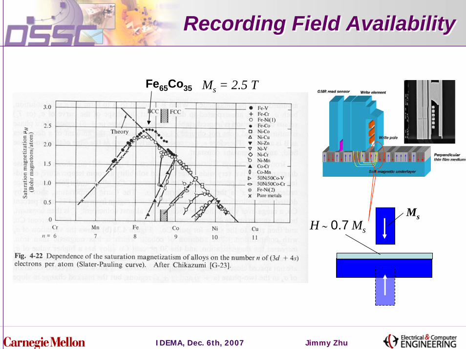
Recording Field AvailabilityRecording Field Availability
Fe65Co35
MsH ∼ 0.7 Ms
Ms = 2.5 T
IDEMA, Dec. 6th, 2007 Jimmy Zhu
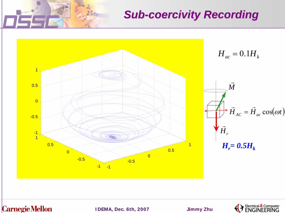
SubSub--coercivity Recordingcoercivity Recording
( )tHH acAC ωcosrr
=
kac HH 1.0
Hr= 0.5Hk
=
-1-0.5
00.5
1
-1-0.5
0
0.51
-1
-0.5
0
0.5
1
rHr
Mr
IDEMA, Dec. 6th, 2007 Jimmy Zhu
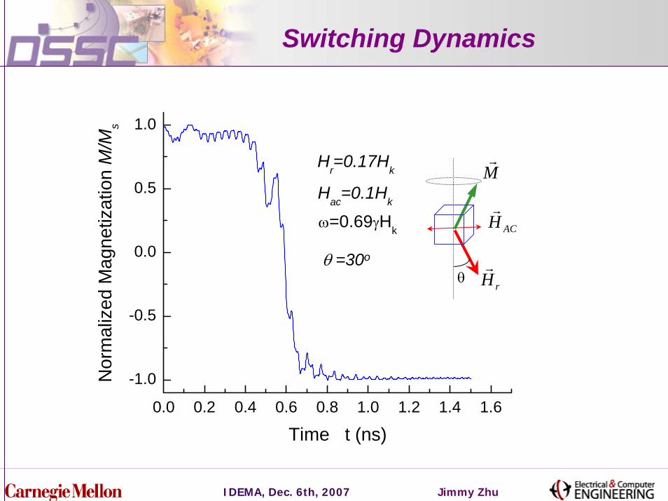
Switching Dynamics
0.0 0.2 0.4 0.6 0.8 1.0 1.2 1.4 1.6
-1.0
-0.5
0.0
0.5
1.0
ω=0.69γHk
Hr=0.17Hk
Nor
mal
ized
Mag
netiz
atio
n M
/Ms
Time t (ns)
Hac=0.1Hk
θ =30o
ACHr
rHr
Mr
θ
IDEMA, Dec. 6th, 2007 Jimmy Zhu
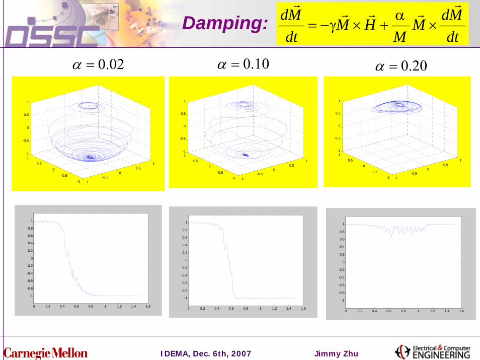
dtMdM
MHM
dtMd
rrrr
r
×α
+×γ−=Damping:
10.0=α
-1-0.5
00.5
1
-1-0.5
0
0.51
-1
-0.5
0
0.5
1
02.0=α 20.0=α
-1-0.5
00.5
1
-1-0.5
0
0.51
-1
-0.5
0
0.5
1
-1-0.5
00.5
1
-1-0.5
0
0.51
-1
-0.5
0
0.5
1
0 0.2 0.4 0.6 0.8 1 1.2 1.4 1.6
-1
-0.8
-0.6
-0.4
-0.2
0
0.2
0.4
0.6
0.8
1
0 0.2 0.4 0.6 0.8 1 1.2 1.4 1.6
-1
-0.8
-0.6
-0.4
-0.2
0
0.2
0.4
0.6
0.8
1
0 0.2 0.4 0.6 0.8 1 1.2 1.4 1.6
-1
-0.8
-0.6
-0.4
-0.2
0
0.2
0.4
0.6
0.8
1
IDEMA, Dec. 6th, 2007 Jimmy Zhu
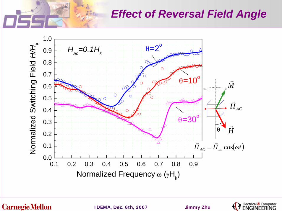
Effect of Reversal Field Angle
0.1 0.2 0.3 0.4 0.5 0.6 0.7 0.8 0.90.0
0.1
0.2
0.3
0.4
0.5
0.6
0.7
0.8
0.9
1.0
θ=30o
θ=10o
θ=2oHac=0.1Hk
Nor
mal
ized
Sw
itchi
ng F
ield
H/H
k
Normalized Frequency ω (γHk)
ACHr
Hr
Mr
θ
( )tHH acAC ωcosrr
=

IDEMA, Dec. 6th, 2007 Jimmy Zhu
Reversal Field Angular Dependence
0 5 10 15 20 25 30 35 40 45 500.0
0.1
0.2
0.3
0.4
0.5
0.6
0.7
0.8
0.9
1.0
Hac
=0.1Hk
With AC Field (Broadband)
Stoner-Wohlfarth Model
Nor
mal
ized
Sw
itchi
ng F
ield
H/H
k
Reversal Field Angle θ (degree)
ACHr
Hr
Mr
θ
IDEMA, Dec. 6th, 2007 Jimmy Zhu
OutlineOutline
Microwave assisted magnetic recording
Generating localized microwave field: spin torque
Analysis of AC field generation
Recording simulation
Summary
IDEMA, Dec. 6th, 2007 Jimmy Zhu
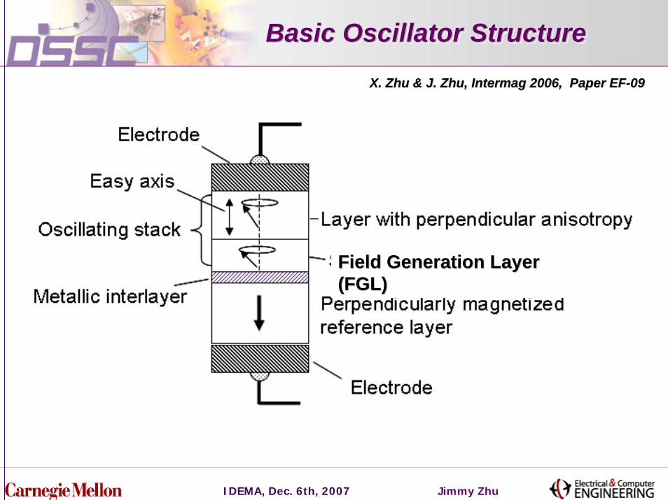
Basic Oscillator StructureBasic Oscillator StructureBasic Oscillator Structure
X. Zhu & J. Zhu, Intermag 2006, Paper EFX. Zhu & J. Zhu, Intermag 2006, Paper EF--0909
Field Generation Layer Field Generation Layer (FGL)(FGL)
IDEMA, Dec. 6th, 2007 Jimmy Zhu
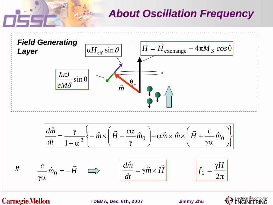
About Oscillation FrequencyAbout Oscillation FrequencyAbout Oscillation Frequency
Field Generating Field Generating LayerLayer θπ4exchange cosMHH S−=
rr
mrθθ
θsinα effH
θsinδ
εeM
Jh
⎭⎬⎫
⎩⎨⎧
⎟⎟⎠
⎞⎜⎜⎝
⎛γα
+××α−⎟⎟⎠
⎞⎜⎜⎝
⎛γα
−×−α+
γ= 0021
m̂cHm̂m̂m̂cHm̂dtm̂d rr
Hm̂dtm̂d r
×γ=π
γ=
20HfHm̂c r
−=γα 0
If
IDEMA, Dec. 6th, 2007 Jimmy Zhu
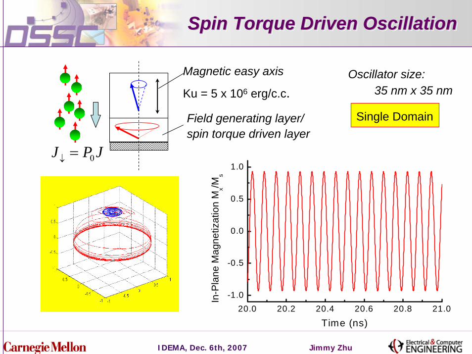
Spin Torque Driven OscillationSpin Torque Driven OscillationSpin Torque Driven Oscillation
20.0 20.2 20.4 20.6 20.8 21.0-1.0
-0.5
0.0
0.5
1.0
In-P
lane
Mag
netiz
atio
n M
x/Ms
Time (ns)
JPJ 0=↓
Magnetic easy axis Oscillator size: 35 nm x 35 nmKu = 5 x 10⁶ erg/c.c.
Field generating layer/ spin torque driven layer
Single Domain
IDEMA, Dec. 6th, 2007 Jimmy Zhu
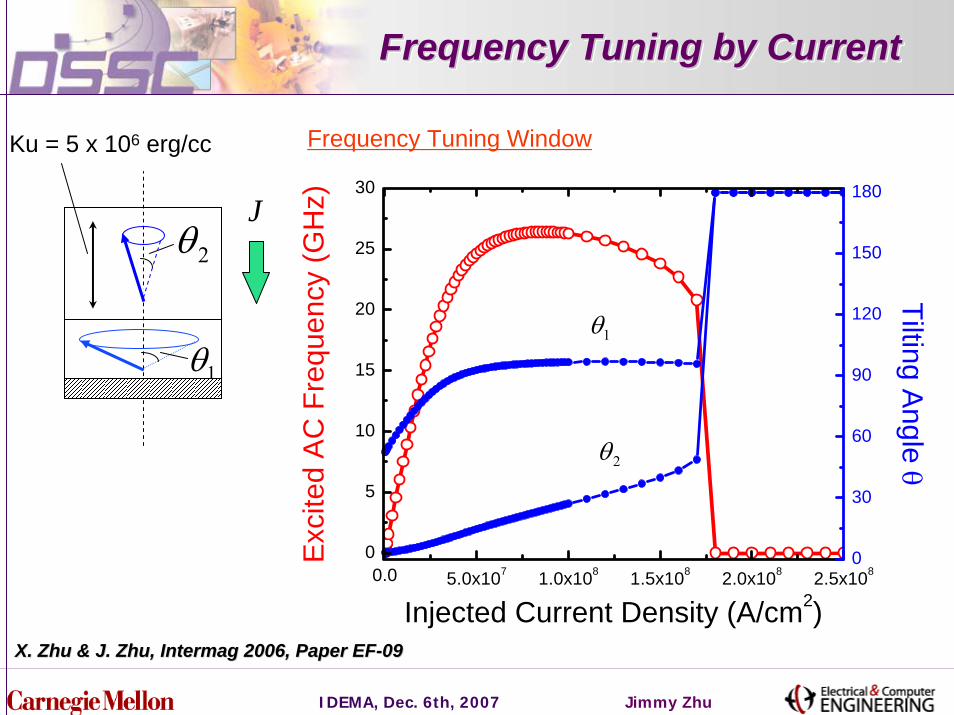
Frequency Tuning by CurrentFrequency Tuning by CurrentFrequency Tuning by Current
0.0 5.0x10⁷ 1.0x10⁸ 1.5x10⁸ 2.0x10⁸ 2.5x1080
5
10
15
20
25
30
Injected Current Density (A/cm2)
Exc
ited
AC
Fre
quen
cy (G
Hz)
0
30
60
90
120
150
180
Tilting Angle θ
1θ
2θ
Frequency Tuning WindowKu = 5 x 10⁶ erg/cc
J
1θ
2θ
X. Zhu & J. Zhu, Intermag 2006, Paper EFX. Zhu & J. Zhu, Intermag 2006, Paper EF--0909
IDEMA, Dec. 6th, 2007 Jimmy Zhu
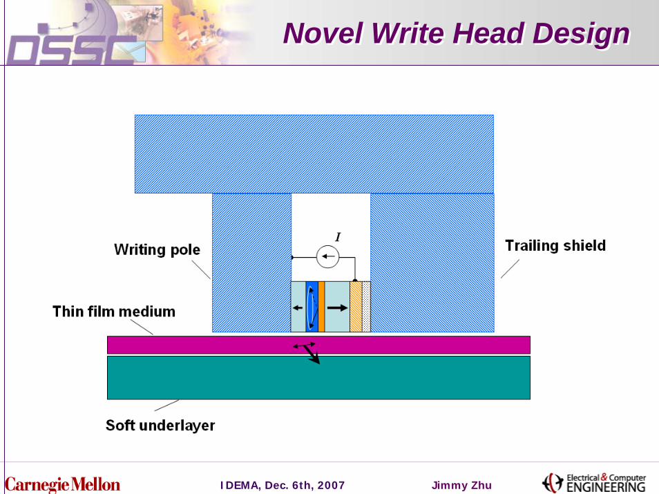
Novel Write Head DesignNovel Write Head Design
IDEMA, Dec. 6th, 2007 Jimmy Zhu
OutlineOutline
Microwave assisted magnetic recording
Generating localized microwave field: spin torque
Analysis of AC field generation
Recording simulation
Summary
IDEMA, Dec. 6th, 2007 Jimmy Zhu
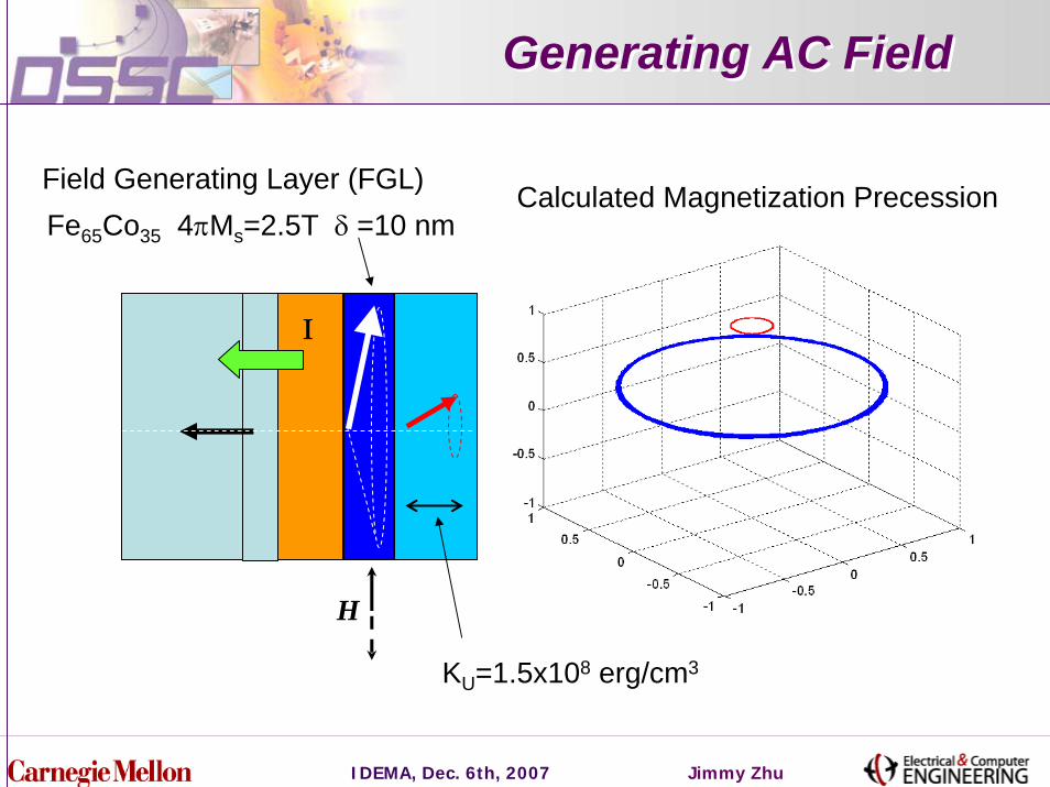
Generating AC FieldGenerating AC Field
Field Generating Layer (FGL) Calculated Magnetization PrecessionFe65Co35 4πMs=2.5T δ =10 nm
Ι
H
KU=1.5x10⁸ erg/cm3
IDEMA, Dec. 6th, 2007 Jimmy Zhu
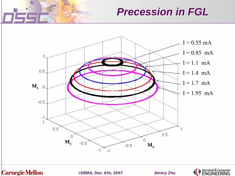
Precession in FGLPrecession in FGL
I = 0.55 mA
I = 1.95 mA
I = 1.7 mA
I = 1.4 mA
I = 1.1 mA
I = 0.85 mA
MxMy
Mz
IDEMA, Dec. 6th, 2007 Jimmy Zhu
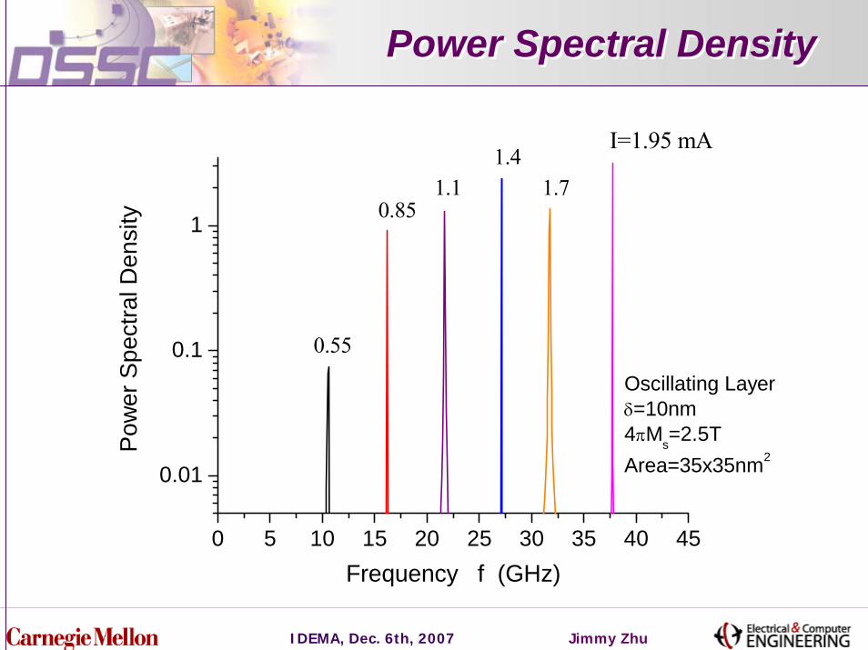
Power Spectral DensityPower Spectral Density
0 5 10 15 20 25 30 35 40 45
0.01
0.1
1
Oscillating Layerδ=10nm4πMs=2.5TArea=35x35nm2
0.55
0.851.1
1.41.7
I=1.95 mAP
ower
Spe
ctra
l Den
sity
Frequency f (GHz)
IDEMA, Dec. 6th, 2007 Jimmy Zhu
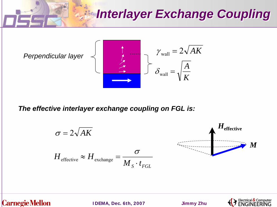
Interlayer Exchange CouplingInterlayer Exchange Coupling
AK2wall =γ
KA
=wallδ
Perpendicular layer
The effective interlayer exchange coupling on FGL is:
M
HeffectiveAK2=σ
FGLS tMHH
⋅=≈
σexchangeeffective

IDEMA, Dec. 6th, 2007 Jimmy Zhu
Field and Injected Current Field and Injected Current
0.0 1.0 2.0 3.0 4.00.0
0.4
0.7
1.1
1.4
1.8
2.2
2.5
2.9
3.2 42GHz35GHz20GHzδ = 15 nm4πMs=2.5T
K=3x10⁸ erg/cm3
K=2x10⁸ erg/cm3
K=1x10⁸ erg/cm3
AC F
ield
Am
plitu
de H
(x10
3 Oe)
Current Density J (x108 A/cm2)
AK2wall =γ
M
Heffective
FGLS tMAKH⋅
≈effective
IDEMA, Dec. 6th, 2007 Jimmy Zhu
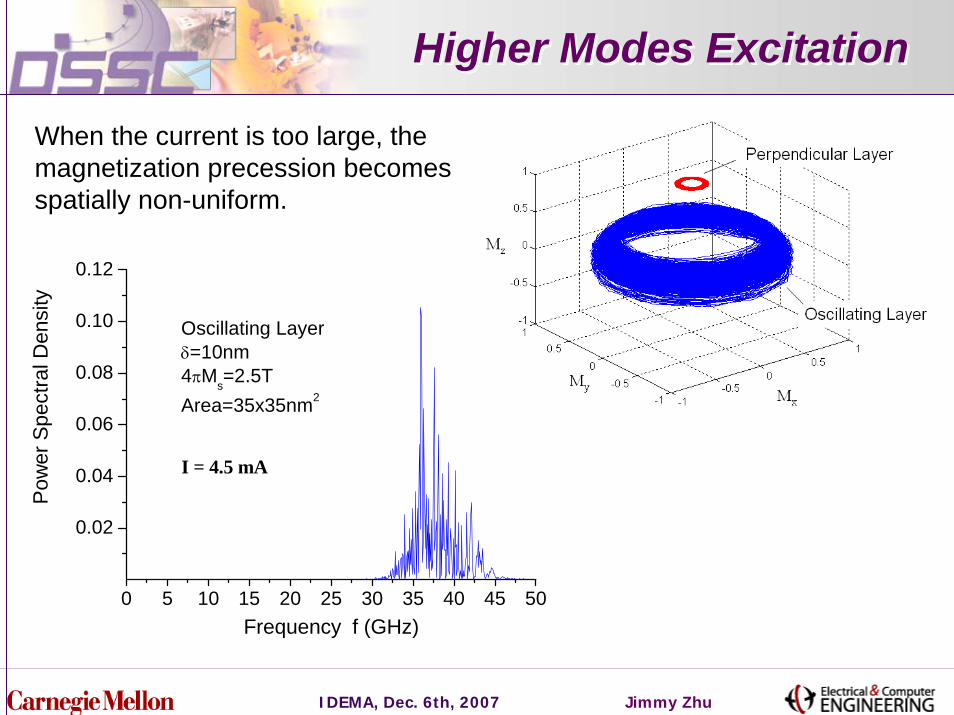
Higher Modes ExcitationHigher Modes Excitation
0 5 10 15 20 25 30 35 40 45 50
0.02
0.04
0.06
0.08
0.10
0.12
I = 4.5 mA
Pow
er S
pect
ral D
ensi
ty
Frequency f (GHz)
Oscillating Layerδ=10nm4πMs=2.5TArea=35x35nm2
When the current is too large, the magnetization precession becomes spatially non-uniform.
IDEMA, Dec. 6th, 2007 Jimmy Zhu
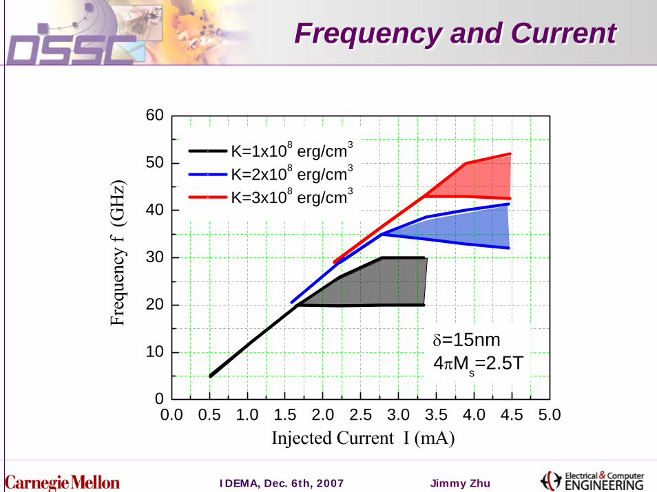
Frequency and CurrentFrequency and Current
0.0 0.5 1.0 1.5 2.0 2.5 3.0 3.5 4.0 4.5 5.00
10
20
30
40
50
60
δ=15nm4πMs=2.5T
K=1x10⁸ erg/cm3
K=2x10⁸ erg/cm3
K=3x10⁸ erg/cm3
Injected Current I (mA)
Fre
quen
cy f
(GH
z)
IDEMA, Dec. 6th, 2007 Jimmy Zhu
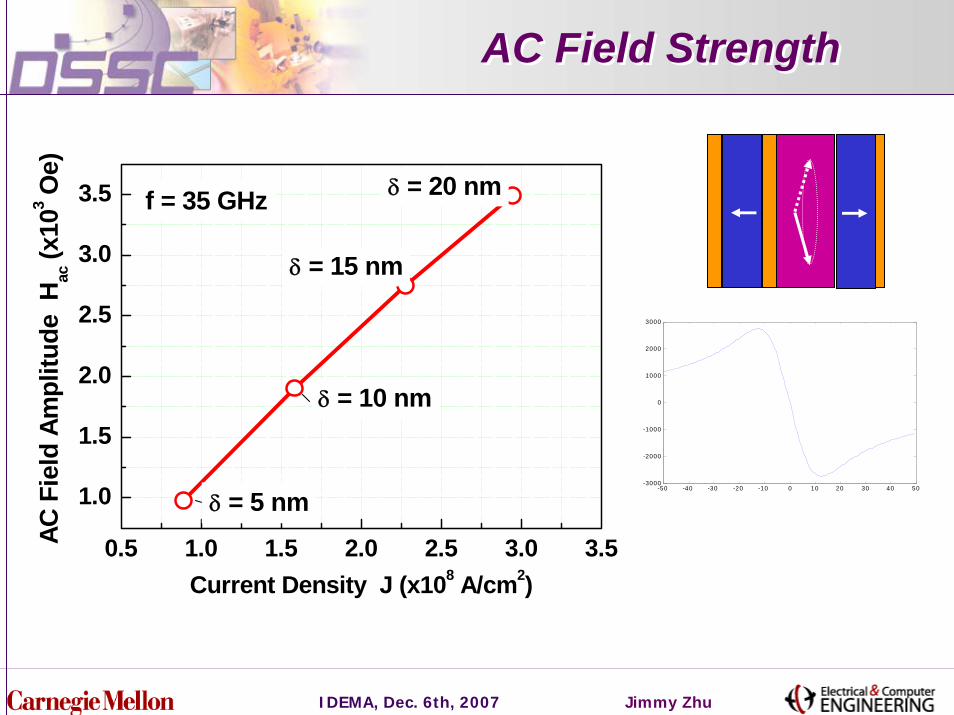
AC Field StrengthAC Field Strength
0.5 1.0 1.5 2.0 2.5 3.0 3.5
1.0
1.5
2.0
2.5
3.0
3.5 f = 35 GHz δ = 20 nm
δ = 15 nm
δ = 10 nm
δ = 5 nm
AC F
ield
Am
plitu
de H
ac (x
103 O
e)
Current Density J (x108 A/cm2)
-50 -40 -30 -20 -10 0 10 20 30 40 50-3000
-2000
-1000
0
1000
2000
3000
IDEMA, Dec. 6th, 2007 Jimmy Zhu
OutlineOutline
Microwave assisted magnetic recording
Generating localized microwave field: spin torque
Analysis of AC field generation
Recording simulation
Summary
IDEMA, Dec. 6th, 2007 Jimmy Zhu
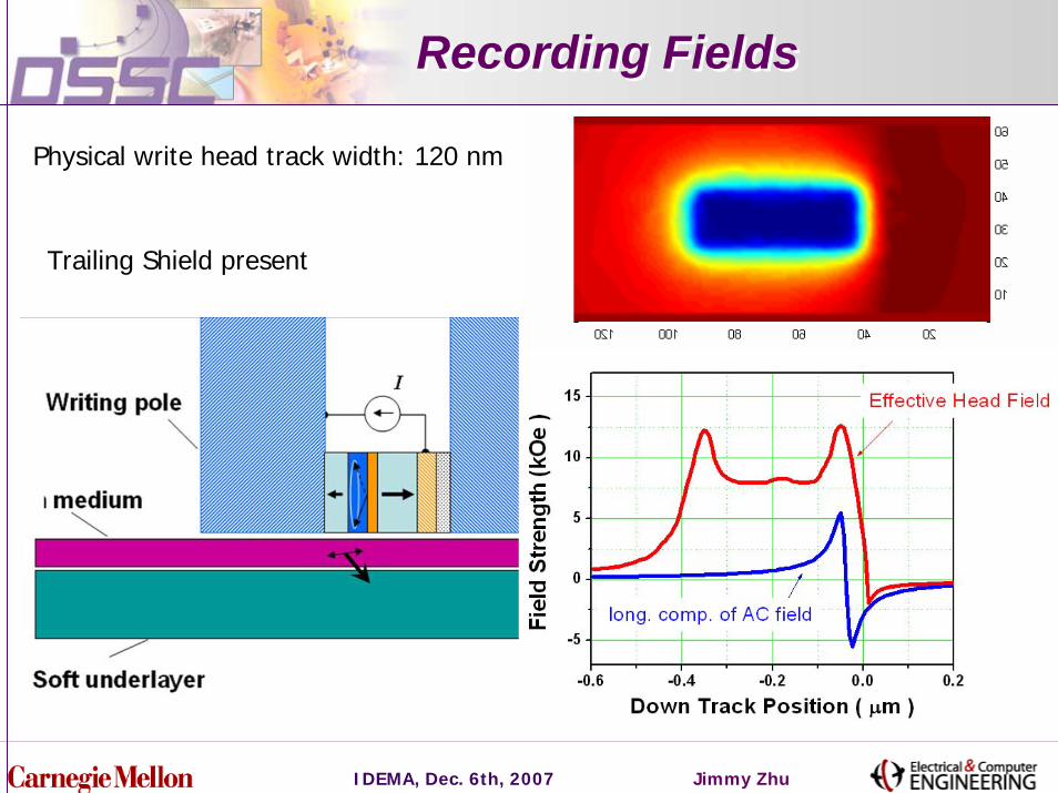
Recording FieldsRecording Fields
Physical write head track width: 120 nm
Trailing Shield present
IDEMA, Dec. 6th, 2007 Jimmy Zhu
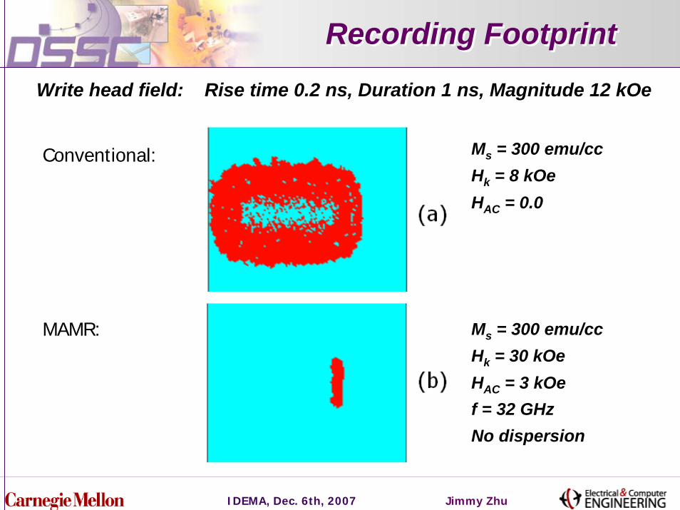
Recording FootprintRecording Footprint
Write head field: Rise time 0.2 ns, Duration 1 ns, Magnitude 12 kOe
Ms = 300 emu/ccHk = 8 kOeHAC = 0.0
Conventional:
Ms = 300 emu/ccHk = 30 kOeHAC = 3 kOef = 32 GHz No dispersion
MAMR:
IDEMA, Dec. 6th, 2007 Jimmy Zhu
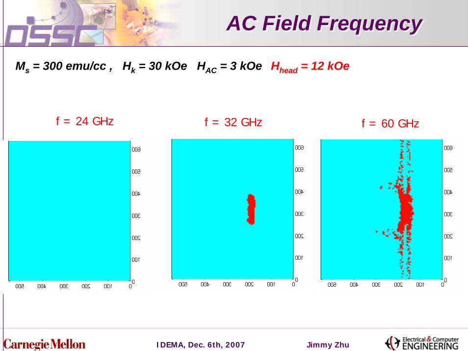
AC Field FrequencyAC Field Frequency
Ms = 300 emu/cc , Hk = 30 kOe HAC = 3 kOe Hhead = 12 kOe
f = 24 GHz f = 32 GHz f = 60 GHz
IDEMA, Dec. 6th, 2007 Jimmy Zhu
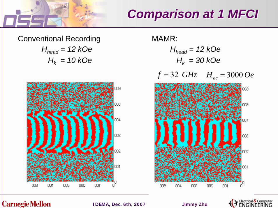
Comparison at 1 MFCIComparison at 1 MFCI
Conventional Recording MAMR: Hhead = 12 kOe
Hk = 10 kOeHhead = 12 kOe
Hk = 30 kOe
GHzf 32= OeHac 3000=
IDEMA, Dec. 6th, 2007 Jimmy Zhu
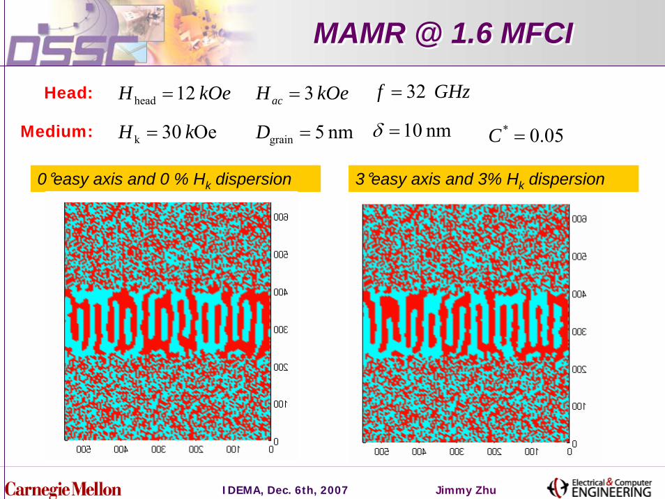
MAMR @ 1.6 MFCIMAMR @ 1.6 MFCI
GHzf 32=Head: kOeH 12head = kOeHac 3=
nm 10=δMedium: Oe 30k kH = nm 5grain =D 05.0* =C
0°easy axis and 0 % Hk dispersion 3°easy axis and 3% Hk dispersion
IDEMA, Dec. 6th, 2007 Jimmy Zhu
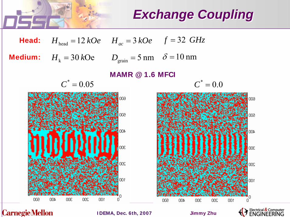
Exchange CouplingExchange Coupling
GHzf 32=Head: kOeH 12head = kOeHac 3=
nm 10=δMedium: Oe 30k kH = nm 5grain =D
05.0* =C 0.0* =CMAMR @ 1.6 MFCI
IDEMA, Dec. 6th, 2007 Jimmy Zhu
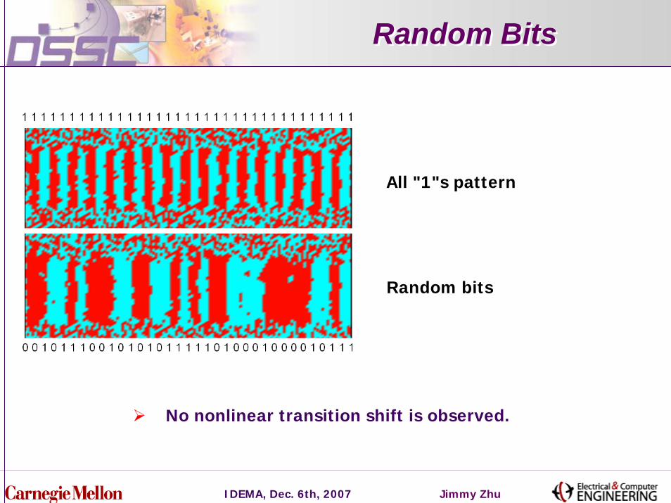
Random BitsRandom Bits
All "1"s pattern
Random bits
No nonlinear transition shift is observed.
IDEMA, Dec. 6th, 2007 Jimmy Zhu
Summary
An in-plane ac field at the FMR frequencies results significant reduction of perpendicular switching field.
The scheme enables recording at a write field that is significantly below the medium coercivity.
Spin momentum transfer can be used to generate localized ac field.
Micromagnetic simulation of recording shows very promising results.