microstructure and tensile properties of carbon-epoxy...
TRANSCRIPT

1
Please note that this is an author-produced PDF of an article accepted for publication following peer review. The definitive publisher-authenticated version is available on the publisher Web site.
Composites Part A: Applied Science and Manufacturing November 2015, Volume 78, Pages 124-134 http://dx.doi.org/10.1016/j.compositesa.2015.07.023 http://archimer.ifremer.fr/doc/00275/38609/ © 2015 Elsevier Ltd. All rights reserved
Achimer http://archimer.ifremer.fr
Microstructure and tensile properties of carbon-epoxy laminates produced by automated fibre placement:
Influence of a caul plate on the effects of gap and overlap embedded defects
Lan Marine 1, *
, Cartié Denis 2, Davies Peter
3, Baley Christophe
1
1 University of South Brittany, LIMATB, Rue de Saint Maudé, 56000 Lorient, France
2 Coriolis Composites SAS, Rue Condorcet, Z.A. du Mourillon, 56350 Quéven, France
3 Ifremer, Centre Bretagne, Technopôle Brest Iroise, 29280 Plouzané, France
* Corresponding author : Marine Lan, email address : [email protected]
Abstract : Automated fibre placement (AFP) enables the trajectory of unidirectional composite tape to be optimized, but laying down complex shapes with this technology can result in the introduction of defects. The aim of this experimental study is to investigate the influence of gaps and overlaps on the microstructure and tensile properties of carbon-epoxy laminates. First, a comparison between a hand-layup and AFP layup, draped and cured under the same conditions, shows equivalent microstructures and tensile properties. This provides the reference values for the study. Then, gap and overlap embedded defects (more or less severe) are introduced during manufacturing, on two cross-ply layups [(0°/(90°)5/0°] and [(90°/0°)2/90°]. Autoclave cure without a caul plate results in local thickness variation and microstructural changes which depend on the defect type. This has a strong influence on mechanical performance. Use of a caul plate avoids these variations and in this case embedded defects hardly affect tensile properties.
Keywords : A. Carbon fibres, B. Automated layup, C. Defects, D. Mechanical properties

1. INTRODUCTION
Composite materials have been used for many years in the aeronautical industry to reduce
aircraft weight and to optimize performance. The traditional manufacturing techniques are
being required to produce increasingly complex shapes while reducing defect levels. In order
to address this, new processes such as AFP (Automated Fibre Placement) have been
developed, which allow the optimization of reinforcement lay-up and close control of process
parameters [1]. An automated fibre placement machine applies tows (of 3.175 mm to 12.7
mm width), in the form of a ribbon of unidirectional prepreg with fibres in either
thermosetting or thermoplastic matrix but also powder tows for RTM, onto the surface of a
mould through a placement head. Thirty-two tows may be placed simultaneously side by side
on the mould surface. The orientation of plies, the precision of draping, repeatability and
reliability of manufactured parts is ensured while reducing mechanical tolerances. This
technology has the advantage of making parts of complex curvilinear shapes, with single or
double curvature, in order to optimize the composite structure [2]. It is also possible to
produce laminates with large thickness variations. The combinations of controlled pressure
exerted by roller compaction and the local application of temperature by a heating system
(infrared lamp or hot air torches) removes air trapped between the layers, reduces porosity and
allows the adhesion of different plies of the laminate to the mould or onto previously draped
plies [3–5]. Following the layup, the manufactured part is placed in an autoclave to
consolidate the laminate plies, polymerizing the resin contained in the prepreg tapes.
Mechanical tests on specimens from laminated AFP components have highlighted an increase
in buckling load [6,7], reduced effects of stress concentrations [8,9] and reduced notch
sensitivity [10].
During the layup of composite parts by AFP, gaps and overlaps are generally avoided so as
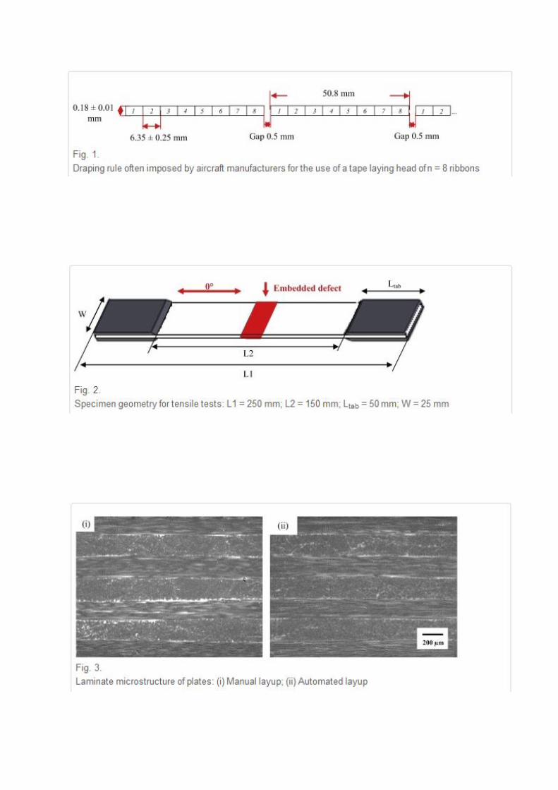
not to impact on the mechanical properties. However, aircraft manufacturers impose a gap of

0.5 mm between each series of n ribbons, with n depending on the placement head used for
draping. Figure 1 illustrates this rule for a tape laying head of n = 8 ribbons. This gap prevents
the creation of an overlap which is generally forbidden by the aircraft manufacturers. The
value of this gap is defined according to the machine tolerances.
During the draping of non-developable surfaces, misalignment of the tows’ edges will be
induced, so management of the gap and/or overlap will be necessary. The AFP programming
software allows optimization of the positioning of the tow drop offs. This option allows the
location of singularities and their dimensions to be understood, but discontinuities may occur.
The tows are cut perpendicular to the fibres and this may create heterogeneous areas
depending on the draping strategy. In addition, gaps and tape overlaps, directly related to
machine and material tolerances, can be introduced and affect the mechanical properties of
the manufactured parts. Research has been conducted for many years to understand the impact
of these constraints on carbon fibre reinforced thermoset materials. There are now methods
which allow the tape laying trajectory to be optimized, to reduce the impact on mechnical
properties [11–13].
Sawicki et al. [14] modelled the influence of gaps and overlaps in plies oriented at 90° to the
loading direction in compression. Ply waviness in defect regions resulted in a loss of
compression strength. Blom et al. [15] presented a numerical investigation of the compression
behaviour that showed the effect of the tow drop areas on AFP laminate panel properties.
They concluded that a significant decrease of the strength and the stiffness results when the
numbers of tows per course increases. The position of the tow drop area influences the
strength and the stress distribution. Turoski [16] performed experimental and numerical tests
to investigate the impact of the number of gaps (one, two, three or four) and offset of gap on
the tensile and compression strength for unnotched and notched quasi-isotropic laminates. He
showed that in tension, the gaps have a smaller effect than when there is an open hole. For

compression, unnotched and notched samples showed failure stress reductions as the number
of gaps increases. In general, the compression tests revealed larger variations than the tension
tests. These previous studies show that the losses in mechanical properties are mainly due to
modifications to the geometry in the gap area, related to thickness variation and out-of-plane
ply waviness.
Croft et al. [17] presented results from an experimental study which allowed the influence of
the main defects (gap, overlap, half spacing /overlap defects and twisting) to be quantified for
laminates loaded in tension, compression and shear. They showed that defects present along
the specimen length caused a larger drop in mechanical properties than defects across the
specimen width. Open-hole test specimens showed a larger variation in properties due to fibre
waviness near defects, which initiated micro-buckling. For open hole compression [18], gaps
and overlaps have a limited effect when they are placed in the loading direction. When plies
are oriented at 90°, the fibre waviness causes a drop in properties. More recently, Falco et al.
[19] studied the effect of fibre angle discontinuities on the un-notched and open-hole tensile
strength of quasi-isotropic laminates. Observation of the geometry of embedded defects and
the resulting mechanical behaviour showed that the influence of gaps was more significant
when staggering rules (offsetting of the defects in successive plies) were not applied.
However the test results showed that an open hole has a stronger negative influence than that
of a gap singularity. The effects of impact and compression after impact were also studied,
experimentally and numerically [20,21].
Li et al. [22] developed a 3D meshing tool to automatically generate gaps and overlaps
numerically. This enabled them to investigate the thickness variations associated with
singularities, as well as out-of-plane ply waviness. Models with different sizes and
distributions of gaps and overlaps were set up in order to study how these singularities affect
properties. Numerical studies have also been performed to examine the influence of gap and

overlap defects on the in-plane stiffness and buckling of laminates laid up by AFP [23–25].
These indicate that overlaps can result in an increase in properties, in contrast to gaps which
tend to weaken these materials.
The aim of the work presented here is to develop an experimental method for the analysis of
the consequences of the presence of singularities, which are introduced by AFP, for the
mechanical properties of carbon/epoxy laminates. Two singularity configurations, gaps and
overlaps, of different geometries, have been deliberately introduced into laminates with
different stacking sequences, in order to examine how they affect tensile properties. The
sequences are only based on 0° and 90° layers and are loaded in tension to avoid membrane-
bending coupling. First, a comparison is made between a plate produced by hand layup and
one made by AFP, without embedded defects , in order to provide reference values. Then
plates with two stacking sequences but the same number of 0° plies, [0°/90°5/0°] and
[(90°/0°)2/90°], were prepared with embedded defects . These sequences were chosen to study
first an extreme case, with superposed embedded defects , then a more realistic case. The
embedded defects were only introduced in the 90° plies. C-scan inspections were used to
check the quality of all plates. Then scanning electron microscopy (SEM) was used to
examine the microstructure of the stacks at the location of embedded defects in detail.
Finally, tensile loading enabled the influence of the embedded defects on tensile properties to
be quantified. Plates were cured both with and without a caul plate; caul plates are often but
not always used during cure in the aeronautical industry. The influence of this plate is
examined as it has a strong effect on both geometry and microstructure, but few systematic
studies of caul plate effects on AFP composite performance are available.

2. MATERIALS AND METHODS
2.1. Material
The material studied is carbon-reinforced prepreg (8552/AS4/RC34/AW194) from Hexcel
Composites [26]. The nominal baseline fibre volume fraction and the nominal cured ply
thickness are respectively 57 ± 2 % and 0.18 ± 0.01 mm. Three samples were taken from
different areas in each panel and analyzed to obtain these values. In the case of manual layup,
the prepreg is used directly in its original configuration as unidirectional bands. In the case of
draping with the fibre placement process, the prepreg is presented as a tow of width 6.35 ±
0.25 mm. The unidirectional bands and the tows come from the same batch of material in
order to compare the properties.
2.2. Manufacture of samples
To manufacture the different plates (400 mm wide by 500 mm long), the robotic arm and
placement head developed by Coriolis Composite were used [27]. This enabled 8 prepreg
fibre tows to be draped simultaneously with a total width of 50.8 mm (8*6.35 mm) per course.
Heating was by an IR lamp which provides localized heat to enhance adhesion between the
successive plies. A compaction force of 100 N was applied during the draping operation. The
draping speed was 0.1 m/s. To obtain a smooth surface, the first ply was draped over a film of
Teflon Wrightlon 5200 supplied by Airtech® maintained by vacuum. Finally, to make a gap
or overlap, the software of the fibre placement machine was programmed by indicating in the
draping program either not to place a tow or to place an extra tow.
2.3. Processing cycle
The autoclave cycle imposed on samples respects the conditions of polymerization of pre-
impregnated carbon/epoxy provided by the supplier of the material (110°C during 60 min
followed by 180°C for 120 min with a maximum autoclave pressure of 7 bars).
The specifications of aircraft manufacturers for the autoclave polymerization of structural
parts sometimes require the application of a caul plate acting as a backing mould. This caul
plate is generally made of thin metal or CFRP laminate, positioned within the vacuum bag.
The purpose of this caul plate is to allow a better final consolidation of parts and a smooth
surface finish. To determine the influence of this caul plate on the microstructure of lay-ups
draped by AFP, a series of plates containing defects was polymerized without a caul plate.
All the other plates of this study were polymerized according to the specifications of aircraft
manufacturers with a 2 mm thick aluminium caul plate. Wrigthlon 5200 release film supplied
by Airtech® were used between to mould surface and the panel as well as between the panel
and the caul plate to permit the flow of the material.
2.4. Ultrasonic C-Scan inspections
For this study, ultrasonic C-Scan was chosen for analysis of the sample material health. The
ultrasonic C-scan equipment (Sofratest 49944) used for the inspections was equipped with a
transducer and a plane aluminium panel acting as a reflector. For these inspections, the plates
were placed on the reflector on spacers and immersed in a tank containing water. The control
was performed by a focused transducer, with a frequency of 10 MHz and a focalization length
of 76 mm, which scans in the X and Y directions thanks to a motorized system that allows the
entire surface of the part to be covered. The acquisition step is one millimeter, in all cases a
measurement was made at the centre of the defect region .

2.5. SEM analysis
The morphology of embedded defects and the organization of plies have been observed with
a Jeol JSM 6460 LV scanning electron microscope (SEM). The area examined was located in
the middle of the plates, where the defects introduced during the layup were located. The
samples were cut then polished to 1 micron in order to obtain flat, clean surfaces before
examination.
2.6. Image analysis
Fibre volume fraction and porosity levels were determined using image analysis of SEM
images with ImageJ software. Assemblies of several images were necessary to re-create all
the zones affected by the embedded defects . Contrast was first adjusted, to reveal fibres,
matrix and porosity. The software then quantified the amount of each.
2.7. Mechanical experiments
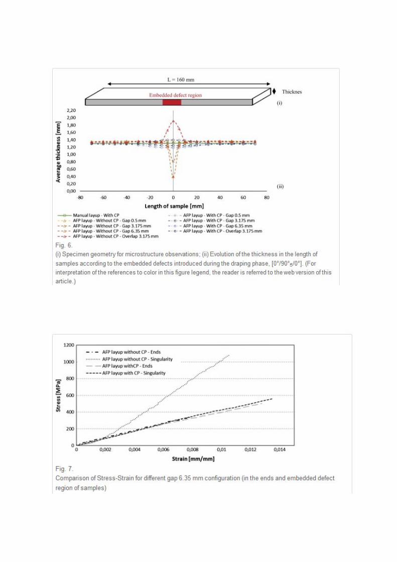
Standard tensile tests were carried out according to the ASTM D3039 [28]. In order to
measure the influence of defects on the mechanical properties in the most critical situation,
defects were placed in the middle of the sample, perpendicular to the direction of tensile
loading (Figure 2 ). These tests were performed on an Instron hydraulic test machine, with a
load cell of 50 kN, at a loading rate of 2 mm/min. In order to limit stress concentrations that
may be caused by the clamping system of the tensile testing machine and to avoid premature
failure, aluminium tabs of 2 mm thickness were bonded to each end of the specimen using a
two component epoxy adhesive. For each configuration, an average of eight specimens was
tested.
The Aramis® (GOM, Germany) optical system was used in these tests to measure the full-
field displacements and strains on the outer plies with Digital Image Correlation. Longitudinal

strain gauges were also positioned on the other side of the specimen in three locations (one at
the middle of specimen and one at each end) to check strain values.
3. RESULTS AND DISCUSSION
3.1. Comparative study of hand layup and layup by AFP
Two plates consisting of 7 plies with a [(0°/90°)3/0°] stacking sequence were laid up. The
first was laid by hand, using standard industrial practice. The second was laid up by AFP with
bands cut from the same roll of prepreg as the hand lay-up plate, applying an aeronautical
procedure (respecting a space of 0.5mm between each passage of the placement head, Figure
1). The two plates were cured at the same time in the same autoclave with caul plates.
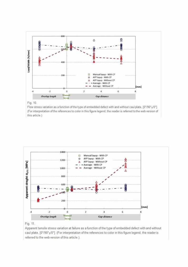
C-Scan and SEM observations revealed the microstructure of both composites. Fibre volume
fractions were determined to be 58.5 % and 59.7 % for the hand and AFP lay-ups
respectively. Impregnation quality was good for both, see Figure 3 (i) and Figure 3 (ii), with
low porosity levels around 0.01% and 0.02%. Only a small number of micro porosities, of
diameters similar to carbon fibre diameter, were noted in interply regions.
The final thickness of both materials was similar as will be shown below. Tensile tests on the
two materials showed very similar properties, with modulus values close to the estimated
value of 84.8 GPa based on suppliers’ fibre and matrix properties (the theoretical longitudinal
modulus and the theoretical transverse modulus are respectively 141 GPa and 10 GPa).
There is no significant difference between the microstructures or the tensile properties for
plates layup by hand or AFP then cured with a caul plate, so these values will now be used as
a reference to examine the influence of embedded defects .

3.2. Stacking with embedded defects in five superimposed plies
The aim of the first series of tests was to introduce extreme examples of superposed gaps and
overlaps into a sensitive stacking sequence in order to assess their effects. It should be
emphasized that this is a very severe test case.
Two series of four plates, each with seven plies [0°/90°5/0°], were manufactured by AFP. A
reference plate was produced with the same sequence at the same time for comparison. The
defects have been designed to represent the most critical situations. Indeed, they were
introduced into the plies oriented at 90° and superimposed on each other at the centre of each
of the plates, Figure 4. The dimensions of the defects have also been exaggerated to
accentuate their effects on mechanical properties. They are equivalent to either half the width
of a tow (3.175 mm) or the complete width (6.35 mm).
The first configuration plate studied is draped manually from unidirectional plies, Figure 4 (i).
This plate is the reference plate which contains no singularity. The second configuration
studied is a gap of 0.5 mm, Figure 4 (ii), imposed between each passage of the placement
head. This plate is considered to be the aeronautical reference for the AFP process. The third
configuration, Figure 4 (iii) studied is a gap of 3.175 mm. This singularity is obtained by
programming a gap of the equivalent of half tow in the center of the plate in each 90° plies.
This defect is commonly induced during the production of curved parts when passing from
one sector to another. The fourth pattern corresponds to the creation of a gap of 6.35 mm
width, Figure 4 (iv). This configuration simulates the absence of a ribbon in the centre of the
plate in 90° oriented plies. The last configuration studied corresponds to an overlap of 3.175
mm, Figure 4 (v). This configuration corresponds to addition of the equivalent of a half-tow at
the centre of the plate and thus creates a local extra thickness of the plies at 90°. This defect
may arise during the manufacture of a complex shape which results in a variation of the
position of the ribbons.

The first series of four plates was manufactured with a caul plate. A second series of four
plates with exactly the same stacking sequence and embedded defects was then produced
without the caul plate. C-scan inspection of all plates indicated no significant defects outside
the singularity regions. Only a variation in thickness revealed the presence of defects in
samples cured without a caul plate.
Observation of the material microstructure is essential in order to understand the influence of
gap and overlap defects , so all plates were examined. SEM micrographs of the hand layup
and AFP reference plates are shown in Figure 5 (i) and Figure 5 (ii) and reveal good quality
laminates and similar thicknesses. Plates with gap defects (3.175 mm and 6.35 mm) reveal a
quite different microstructure depending on whether a caul plate is used or not, Figure 5 (iii)
and Figure 5 (iv). The large white regions in these images are unreinforced resin. When no
caul plate is used there is a local significant reduction in plate thickness. For the 6.35mm gap
the 5 plies at 90° are no longer visible in the gap area. The use of a caul plate for plates with
the same allows the gaps to be filled during cure and only the appearance of resin rich regions
at the 0°/90°interface reveals their presence. For the overlap a local increase in thickness is
noted (Figure 5 (v)), which is reduced by the presence of the caul plate.
The pressure exerted by the caul plate assists the movement of the material in the singularity
zone during autoclave cure and compacting is more homogeneous, limiting porosity
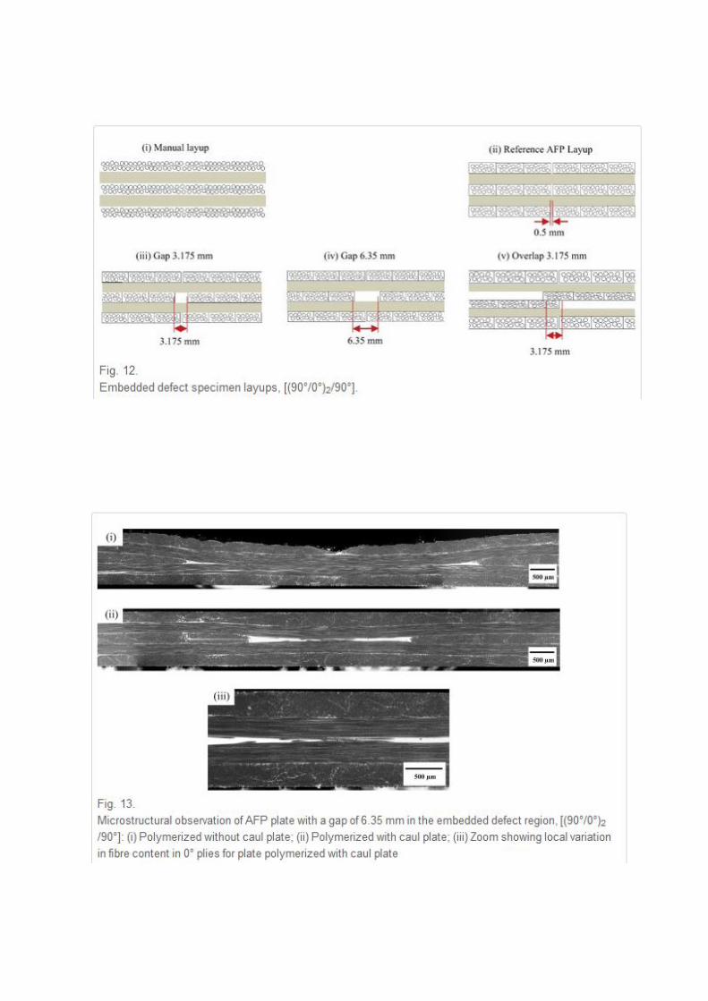
development near the embedded defects . The cure step is critical in determining the final
microstructure and the caul plate limits the thickness variations in the length of samples,
introduced during lay-up, as shown in Figure 6. These values were determined with a
micrometer and checked by image analysis of SEM images. Values for the distance over
which there is a variation in microstructure, i.e. the zone where ply waviness or swelling of
the 0° plies occurs due to the presence of the embedded defects, vary considerably . If caul
plates are not used large thickness variations are noted except for the reference plates (0.5mm
gap).
Figure 7 shows an example of stress-strain plots for 6.35mm gap specimens with and without
caul plates. Two plots of apparent stress are shown for the case without caul plate, one using
the local thickness at the gap and a second using the thickness away from the gap; it is clear
that locally the stress is much higher, but in the gap region only 0° plies are present,
elsewhere in the specimen the response is similar to that of the plates with caul plates. Figure
8 shows examples of strain measurements.
The modulus values from all the tests are shown in Figure 9. These are calculated using the
local thickness to determine the stress, and strain measurements in the embedded defect
region, the latter obtained using DIC. It should be emphasized that these are apparent modulus
values strongly influenced by both the 0° plies remaining when 90° reinforcement leaves the
zone and by the modified thickness. The theoretical modulus of this laminates is 47.4 GPa.
There is no significant variation for specimens with embedded defects , values vary by about
4% compared to the AFP reference value in zones away from the singularity. The absence of
a caul plate does not affect this value either. In the specimen centre close to the singularity,
the absence of a caul plate results in significant thickness and microstructure variations as
shown above, and this is reflected in the local moduli. When the caul plate is employed the
differences are small, a maximum variation of 14% is measured. Gap defects reduce
thickness and increase local modulus while overlaps increase thickness and reduce modulus.
Sample strength can be evaluated in terms of load flux, a tensile load normalized by specimen
width but not including thickness. These values are shown in Figure 10. For the specimens
manufactured with a caul plate these values vary little when embedded defects are
introduced. For plates cured without caul plates however, the presence of gaps and embedded
defects result in significant drops in load flux, with a reduction of 35% for the overlaps.
The failure behaviour can also be analysed using an apparent stress estimated for the central
zone of the sample using the measured local thickness, Figure 11. These tests are performed
with the loading in the direction perpendicular to the 5 plies at 90°, but final failure is
governed by the two outer plies at 0°. For specimens from the plate cured with a caul plate
final failures are randomly distributed along the specimens when embedded defects are
present. The small variations in stress correspond to the very small thickness variations. When
caul plates were not employed all failures occurred at the embedded defects except for the
reference AFP specimens. The large variation in apparent strengths for the latter is a result of
both thickness variations and local ply orientation. The gap of 6.35 mm leads to swelling of
the 0 ° plies due to the significant presence of excess resin . The absence of 90° fibres leads to
an increase of the apparent strength, while the 3.175 mm overlap causes a local increase in
thickness and a drop in local 90° fibre content resulting in a large drop in break stress.
In summary, the use of a caul plate ensures that the applied autoclave pressure is mostly
reacted at high thickness spots in the lay-up, generating the localised pressure gradients that
are needed to cause flow to equalize the thickness. As a result the influence of gap and
overlap defects on tensile properties are very small even for this extreme [0°/90°5/0°]
stacking sequence with superposed embedded defects . Without the caul plate during cure the
large thickness and microstructure variations can promote either higher or lower properties.
The stacking sequence adopted in this first study, with singularities superposed in the centre
of the plate, is an extreme situation. The lay-up rules applied in the aeronautical industry are
designed to avoid such a “worst case”, and the fibre placement robots are equipped to detect
missing tapes during lay-up. In order to complete this study of the influence of caul plates on
embedded defects a second more traditional lay-up was therefore examined.

3.3. Stacking with embedded defects in single ply
The aim of this second part of the study was to examine the influence of gap and overlap
defects on an alternating ply laminate. This stacking sequence, [(90°/0°)2/90°], is
manufactured in a more standard fashion by alternating the 0° and 90° plies and would be
expected to be more sensitive to defects as the single alternating plies will restrict flow during
cure to a greater extent than in the previous laminate, which contained a block of similar plies.
Two series, each of four plates, were manufactured by AFP, with the same embedded defects
as in the first part of the study, with and without caul plates, Figure 12. A hand lay-up
reference plate was also made. The embedded defects were introduced into the central ply at
90°. The other plies respected the 0.5 mm gap between passes, as shown in Figure 1.
All plates were inspected by C-scan and no macro-porosities were revealed. Only a thickness
variation was noted near the gaps and overlap for the plates cured without caul plates. For the
plates with 0.5 mm gaps there was no influence of the caul plate on the microstructure. For
the plates with gap of 3.175 and 6.35 mm ( Figure 13), the microstructures are similar, with
resin-rich zones and missing 90° reinforcement in the central ply. The caul plate again results
in significantly reduced thickness variations for all the alternate ply laminates compared to
those without caul plates, Figure 14. However, the singularity is not completely filled even
with the caul plate due to the restricting effect of adjacent plies on material movement (Figure
3 (ii) ). When an overlap is introduced in the central ply, there is an over-thickness with and
without the caul plate, but the microstructure is less disturbed when the caul plate is present.
Figure 15 shows the measured moduli values. The theoretical modulus of this laminates is
62.4 GPa. The variations in this modulus for specimens with defects , at the specimen ends,
are not significant even for cure without a caul plate (less than 6%). In the central sections
close to the embedded defects , a small drop is noted for specimens with caul plates, due to

the small variation in microstructure. When there is no caul plate a marked influence of the
singularity is apparent as a result of reduced local thickness (Figure 14).
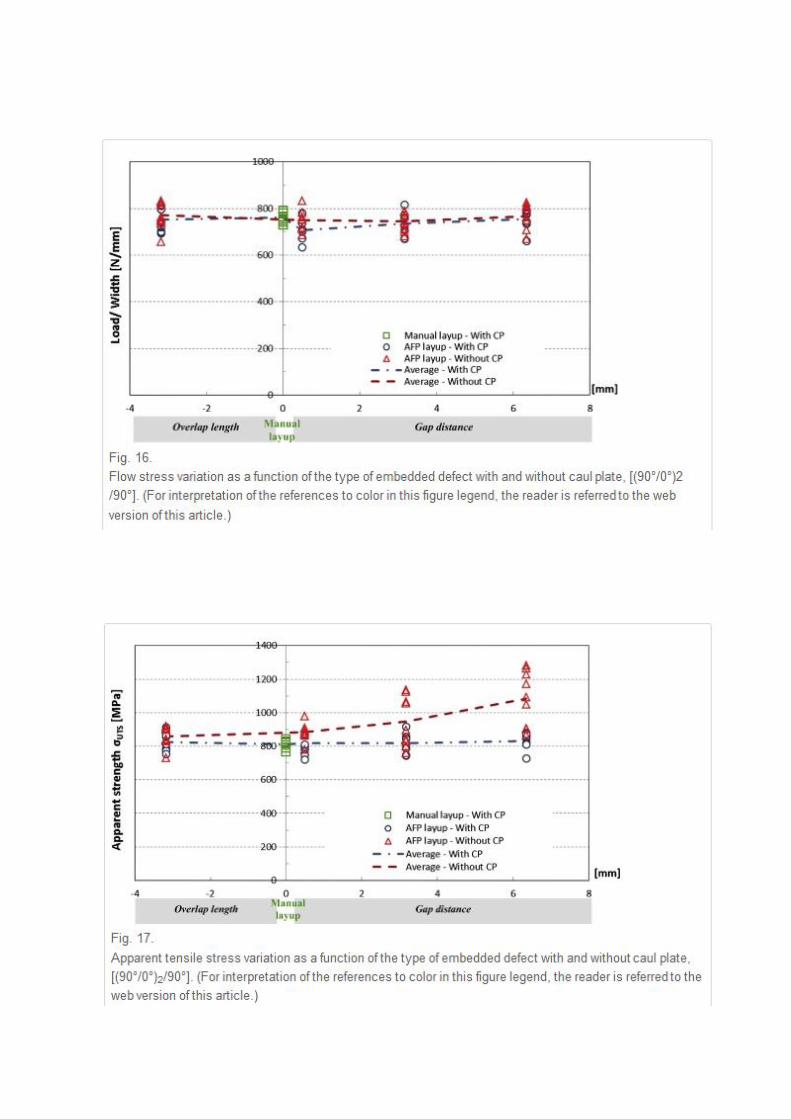
Figure 16 shows the load flux at failure and it is interesting to note that there is no significant
influence of these embedded defects , with or without caul plate. The variations in thickness
do not affect the ability of the material to transfer load as the 0° plies are in place and there is
no global stress concentration effect in the singularity region.
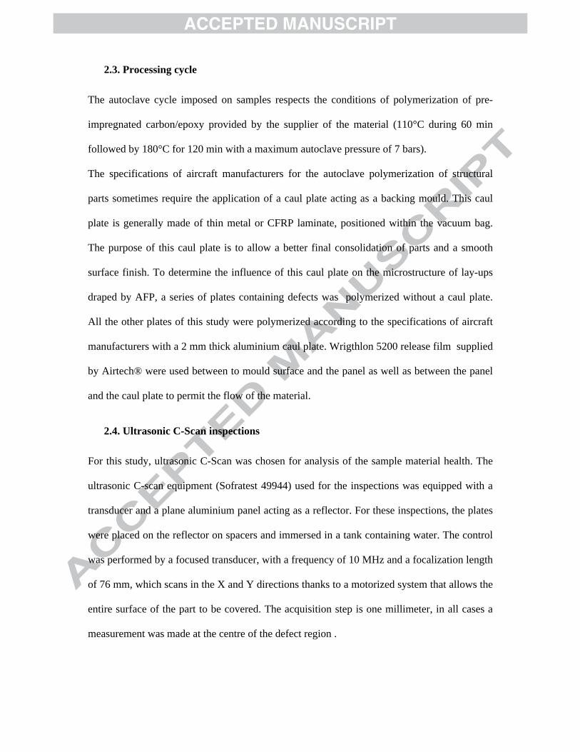
Figure 17 shows the local apparent stresses at failure estimated in the singularity region.
Again, as for the previous stacking sequence when caul plates are used the failures occur
randomly along the specimens. A maximum variation of tensile properties of 5% is measured
between the AFP reference plate and the plate containing an overlap. Without caul plates the
failures occur close to the singularity and here the apparent break stresses tend to increase as
thickness decreases, but even for the overlap case there is no drop in stress compared to the
reference values.
In summary for this alternate ply stacking sequence the caul plate is less effective in
homogenizing the material at gaps and overlaps than for the sequence with a block of 90°
plies. However, in spite of significant thickness variations, particularly if caul plates are not
used during cure, the properties in tension vary very little in spite of large initial embedded
defects .
4. CONCLUSION
In the present experimental study, the influence of the presence of a caul plate during cure has
been quantified for different gap and overlap defects. Both microstructure and tensile
behaviour of two cross-ply layups [0°/90°5/0°] and [(90°/0°)2/90°] have been examined.
A first comparison between specimens draped manually and draped by AFP indicated no
differences between either the microstructure of the laminates or their mechanical properties,
and provided baseline reference values.
Different gap and overlap singularities were then introduced. First, an extremely severe
stacking sequence was studied, [0°/90°5/0°] with five superposed embedded defects . The
presence of a caul plate during cure reduces thickness variations and encourages resin flow so
that even large singularities are attenuated, and tensile properties vary by less than 10% with
respect to the reference values. Without the caul plate large thickness variations and resin-rich
regions cause significant changes in tensile properties.
In a second series of tests a more realistic stacking sequence was employed, [(90°/0°)2/90°],
with embedded defects in only one ply. In this case the defects remain after cure but their
dimensions are reduced. Again, tensile properties change little with a caul plate but the
absence of a caul plate results in property changes due to local thickness variations.
Overall, in spite of the introduction of large embedded defects during lay-up, which affect
both local microstructure and geometry, their influence on tensile properties is surprisingly
small in all cases when the sample was polymerized with a caul plate.
In order to complete this study it is important to quantify the influence of these singularities
under other loading conditions. Tests have been performed under in-plane shear and
compression loading, and results from these will be presented subsequently. The next step is
to examine how these defects affect properties of more complex structures.
ACKNOWLEDGEMENTS
The authors would like to thank the region of Brittany (France) and the Regional Council of
Morbihan for their financial support. The authors are also pleased to express their grateful
acknowledgements to Mathieu Gestalin and Amaury Ducloux (Coriolis Composite) for the
manufacture of plates by Automated Fibre Placement, and to Luc Riou (Ifremer) for the
ultrasonic C-Scan analysis.

REFERENCES
[1] Lukaszewicz DH-JA, Ward C, Potter KD. The engineering aspects of automated prepreg layup: History, present and future. Composites Part B: Engineering 2012;43:997–1009. doi:10.1016/j.compositesb.2011.12.003.
[2] Goldworthy WB. Geodesic path length compensator for composite-tape placement head. 3810.805, n.d.
[3] Lukaszewicz DH-JA. Optimisation of high-speed automated layup of thermoset carbon-fibre preimpregnates. Ph.D. University of Bristol, 2011.
[4] Lukaszewicz DH-JA, Potter KD. The internal structure and conformation of prepreg with respect to reliable automated processing. Composites Part A: Applied Science and Manufacturing 2011;42:283–92. doi:10.1016/j.compositesa.2010.11.014.
[5] Lukaszewicz DH-JA, Potter KD, Eales J. A concept for the in situ consolidation of thermoset matrix prepreg during automated lay-up. Composites Part B: Engineering 2013;45:538–43. doi:10.1016/j.compositesb.2012.09.008.
[6] Lopes CS, Gürdal Z, Camanho PP. Variable-stiffness composite panels: Buckling and first-ply failure improvements over straight-fibre laminates. Computers & Structures 2008;86:897–907. doi:10.1016/j.compstruc.2007.04.016.
[7] Gürdal Z, Tatting BF, Wu CK. Variable stiffness composite panels: Effects of stiffness variation on the in-plane and buckling response. Composites Part A: Applied Science and Manufacturing 2008;39:911–22. doi:10.1016/j.compositesa.2007.11.015.
[8] Cairns DS, Ilcewicz LB, Walker T. Far-field and near-field strain response of Automated Tow-Placed laminates to stress concentrations. Composites Engineering 1993;3:1087–97. doi:10.1016/0961-9526(93)90023-D.
[9] Lopes CS, Gürdal Z, Camanho PP. Tailoring for strength of composite steered-fibre panels with cutouts. Composites Part A: Applied Science and Manufacturing 2010;41:1760–7. doi:10.1016/j.compositesa.2010.08.011.
[10] Cairns DS, Ilcewicz LB, Walker T, Minguet PJ. Fracture scaling parameters of inhomogeneous microstructure in composite structures. Composites Science and Technology 1995;53:223–31. doi:10.1016/0266-3538(95)00022-4.
[11] Blom AW, Stickler PB, Gürdal Z. Optimization of a composite cylinder under bending by tailoring stiffness properties in circumferential direction. Composites Part B: Engineering 2010;41:157–65. doi:10.1016/j.compositesb.2009.10.004.
[12] Arian Nik M, Fayazbakhsh K, Pasini D, Lessard L. Surrogate-based multi-objective optimization of a composite laminate with curvilinear fibers. Composite Structures 2012;94:2306–13. doi:10.1016/j.compstruct.2012.03.021.
[13] Arian Nik M, Fayazbakhsh K, Pasini D, Lessard L. A comparative study of metamodeling methods for the design optimization of variable stiffness composites. Composite Structures 2014;107:494–501. doi:10.1016/j.compstruct.2013.08.023.
[14] Sawicki A, Minguett P. The effect of intraply overlaps and gaps upon the compression strength of composite laminates. 39th AIAA/ASME/ASCE/AHS/ASC Structures, Structural Dynamics, and Materials Conference and Exhibit, American Institute of Aeronautics and Astronautics; 1998.
[15] Blom AW, Lopes CS, Kromwijk PJ, Gurdal Z, Camanho PP. A Theoretical Model to Study the Influence of Tow-drop Areas on the Stiffness and Strength of Variable-stiffness Laminates. Journal of Composite Materials 2009;43:403–25. doi:10.1177/0021998308097675.
[16] Turoski LE. Effects of manufacturing defects on the strength of toughened carbon/epoxy prepreg composites /. 2000.

[17] Croft K, Lessard L, Pasini D, Hojjati M, Chen J, Yousefpour A. Experimental study of the effect of automated fiber placement induced defects on performance of composite laminates. Composites Part A: Applied Science and Manufacturing 2011;42:484–91. doi:10.1016/j.compositesa.2011.01.007.
[18] Legay P. Étude de l’influence de défauts sur les propriétés mécaniques de matériaux composites fabriqués par le procédé de placement de fibres. masters. École Polytechnique de Montréal, 2011.
[19] Falcó O, Mayugo JA, Lopes CS, Gascons N, Costa J. Variable-stiffness composite panels: Defect tolerance under in-plane tensile loading. Composites Part A: Applied Science and Manufacturing 2014;63:21–31. doi:10.1016/j.compositesa.2014.03.022.
[20] Rhead AT, Dodwell TJ, Butler R. The effect of tow gaps on compression after impact strength of robotically laminated structures. Computers, Materials and Continua 2013;35:1–16.
[21] Falcó O, Lopes CS, Mayugo JA, Gascons N, Renart J. Effect of tow-drop gaps on the damage resistance and tolerance of Variable-Stiffness Panels. Composite Structures 2014;116:94–103. doi:10.1016/j.compstruct.2014.05.005.
[22] Li X, Hallett SR, Wisnom MR. Modelling the effect of gaps and overlaps in automated fibre placement (AFP)-manufactured laminates. Science and Engineering of Composite Materials 2015;22:115–29.
[23] Fayazbakhsh K, Arian Nik M, Pasini D, Lessard L. Defect layer method to capture effect of gaps and overlaps in variable stiffness laminates made by Automated Fiber Placement. Composite Structures 2013;97:245–51. doi:10.1016/j.compstruct.2012.10.031.
[24] Arian Nik M, Fayazbakhsh K, Pasini D, Lessard L. Optimization of variable stiffness composites with embedded defects induced by Automated Fiber Placement. Composite Structures 2014;107:160–6. doi:10.1016/j.compstruct.2013.07.059.
[25] Arian Nik M, Lessard L, Pasini D. Size-dependent behavior of laminates with curvilinear fibers made by automated fiber placement�: Science and Engineering of Composite Materials. Science and Engineering of Composite Materials 2014;Volume 22:157–63.
[26] http://www.hexcel.com/fr/ 2015. [27] http://www.coriolis-composites.com/ 2015. [28] American Society for Testing and Materials, ASTM D3039/ASTM D3039M,Test
Method for Tensile Properties of Polymer Matrix Composite Materials. ASTM International; 2014.