microsoft windows server 2008 functionality and features
TRANSCRIPT

Microsoft Windows Server 2008 Functionality and Features
By
Guy Wilkin
Submitted to
the Faculty of the Information Technology Program in Partial Fulfillment of the Requirements for
the Degree of Bachelor of Science in Information Technology
University of Cincinnati
College of Applied Science June 2009

Microsoft Windows Server 2008 Functionality and Features
by
Guy Wilkin
Submitted to
the Faculty of the Information Technology Program in Partial Fulfillment of the Requirements
for the Degree of Bachelor of Science
in Information Technology
© Copyright 2009 Guy Wilkin
The author grants to the Information Technology Program permission to reproduce and distribute copies of this document in whole or in part.
___________________________________________________ __________________ Guy Wilkin Date ___________________________________________________ __________________ Sam Geonetta, Ph.D. Date ___________________________________________________ __________________ Hazem Said, Ph.D. Department Head Date

Wilkin i
Acknowledgements
I would like to give special thanks to Dr. Sam Geonetta, my Senior Design advisor. He
has provided assistance with all stages of this project. His advising included feedback on the
direction of the project, report contents, report formatting and presentation board layout. His
advising was critical in aiding my success in the execution of this project.

Wilkin ii
Table of Contents
Section Page Acknowledgements i Table of Contents ii List of Figures iv
Abstract viii 1. Statement of the Problem 1
1.1 Definition of the Need 1
1.1.1 Hyper-V Server Virtualization 1
1.1.2 Windows Advanced Firewall 2
1.1.3 Terminal Services RemoteApp 2
1.1.4 Network Access Protection 3
2. Project Description and Intended Use 4
3. User Profiles 4
3.1 Systems Administrators 4
3.2 Information Technology Managers 5
4. Design Protocols 5
4.1 Hyper-V 6
4.2 Windows Advanced Firewall 8
4.3Terminal Services RemoteApp 9
4.4 Network Access Protection 11
5. Proof of Concept 12
5.1 Physical Components 12
5.2 Hyper-V Virtualization 14
5.3 Windows Advanced Firewall 25
5.4 TS RemoteApp 39
5.5 Network Access Protection 52

Wilkin iii
6. Timeline 71
7. Budget 72
8. Deliverables 73
9. Testing Plan 73
10. Risk Management Plan 74
11. Conclusion 75

Wilkin iv
List of Figures
Figure 1. Physical Lab Layout 5 Figure 2. Hyper-V Networking via Virtual NICs and Virtual Switch 7 Figure 3. Windows Advanced Firewall Layout 9 Figure 4. TS RemoteApp – Client Server Interaction 10 Figure 5. NAP Server and Switch Layout 11 Figure 6. Project Lab 13 Figure 7. Hyper-V Console on Host Server 14 Figure 8. Physical Adapter Settings 15 Figure 9. Virtual Adapter Settings 16 Figure 10. Virtual Machine Directory 17 Figure 11. Virtual Machine - ID 18 Figure 12. Virtual Machine - XML File 19 Figure 13. Hyper-V Snapshot Feature 20 Figure 14. Snapshot in Progress 20 Figure 15. After Snapshot Completed 21 Figure 16. Changing of Desktop Theme 21 Figure 17. Change Made After Snapshot 22 Figure 18. Applying the Snapshot 23 Figure 19. Applying the Snapshot Verification 23 Figure 20. Status of Applying Snapshot 23 Figure 21. Machine Rolled Back 24

Wilkin v
Figure 22. Firewall Enabled on Virtual Server 25 Figure 23. Windows Firewall Domain Profile 26 Figure 24. Domain Profile Customization 27 Figure 25. Firewall Log Settings 28 Figure 26. Ping without Firewall Rule 29 Figure 27. Outbound Rules 30 Figure 28. Creating New Outbound Rule 30 Figure 29. Custom Rule 31 Figure 30. Applying to All Programs 32 Figure 31. Configuring to Block ICMPv4 33 Figure 32. Applying Rule from Any IP Address to Any IP Address 34 Figure 33. Setting to Block the Connection 35 Figure 34. Applying Rule to All Profiles 36 Figure 35. Naming Rule “ICMP Block” 37 Figure 36. Rule as Seen in Console 37 Figure 37. Failed Ping Request 38 Figure 38. TS RemoteApp Enabled on Virtual Server 39 Figure 39. Terminal Server Settings 40 Figure 40. TS RemoteApp Action Menu 41 Figure 41. RemoteApp Wizard 42 Figure 42. Choosing Programs for TS RemoteApp 43 Figure 43. Final TS RemoteApp Wizard Screen 44 Figure 44. Programs Enabled for TS RemoteApp Access 45
Wilkin vi
Figure 45. Accessing TS RemoteApp from the Client Machine 46 Figure 46. Programs Available to Client User 47 Figure 47. RemoteApp Security Warning 47 Figure 48. Domain Credentials Are Required 48 Figure 49. OpenOffice.org as Seen on Client Machine 48 Figure 50. OpenOffice.org Drawing Application Drawing 49 Figure 51. Image Saved as “smile.odg” 50 Figure 52. Opening “smile.odg” on the Server 51 Figure 53. Network Policy Server Console 52 Figure 54. NAP Network Connection Method 53 Figure 55. NAP System Health Validators 54 Figure 56. Health Validator Properties 55 Figure 57. Setting the Health Validator to Require a Firewall 56 Figure 58. Configuring DHCP for NAP 57 Figure 59. Setting the NAP DHCP Scope and Name 58 Figure 60. Enabling NAP for the DHCP Scope 59 Figure 61. Configuring Scope Options 60 Figure 62. Setting the Default User Class DNS Server IP Address 61 Figure 63. Configuring the DNS Name of the Default DNS Server 62 Figure 64. Configuring the Default NAP Class DNS Server IP Address 63 Figure 65. Configuring the DNS Name of the DNS Server for the Restricted Network 64 Figure 66. NAP Client Configuration Console 65 Figure 67. Verifying the NAP Client Configuration 66

Wilkin vii
Figure 68. Verifying the IP Address assigned to the Client 66 Figure 69. NAP Server Log – Client with Firewall Disabled 67 Figure 70. After Remediation the Client Is Granted Full Access to the Network 68 Figure 71. Pinging 192.168.1.22 (TS-PG1) from VISTA02 69 Figure 72. Unsuccessful Ping Results from the Client to TS-PG1 69 Figure 73. Verifying that the NAP Agent Is not Running on the Client 69 Figure 74. Ipconfig Run on VISTA02 Indicates it is on the Restricted Network 70
Table 1. Systems and Their Functions 9 Table 2. Firewall Log on Server 30 Table 3. Firewall Log from Server – Dropped Packets 38 Table 4. Project Timeline 71 Table 5. Project Budget 72 Table 6. Project Risks 75

Wilkin viii
Abstract
Microsoft Windows 2008 Features and Functionality is a project which explores certain features of Microsoft Windows Server 2008. Many businesses will be upgrading to Windows Server 2008 for their server needs or implementing a new rollout to take advantage of these new features. This project explores and demonstrates Hyper-V, Windows Advanced Firewall, Terminal Services RemoteApp and Network Access Protection. These features provide enhanced security and virtualization. System administrators can use this project as a learning tool from a technical aspect. Information technology managers will be able to use this project to learn more about the new features of Server 2008.

Wilkin 1
Microsoft Windows Server 2008 Functionality and Features 1. Statement of the Problem 1.1 Definition of the Need
Windows Server 2008 is the latest and greatest server operating system out on the market
provided by Microsoft. This operating system release comes with some new features which
includes Hyper-V, Windows Advanced Firewall, Terminal Services RemoteApp (TS
RemoteApp) and Network Access Protection (NAP). Many businesses will be considering
upgrading or implementing Windows Server 2008 into their network infrastructures in the
coming years. Information technology managers need to know what the new features are and
what they do. System administrators need to understand the technical working of these new
features.
1.1.1 Hyper-V Server Virtualization
The main driver for server virtualization is utilization of unused excess capacity of server
processors as most servers, according to Morimoto and Guillet, “run under 5% to 10% processor
utilization” (8, p. 7). Efficiently using server processing power results in savings because
businesses spend less money on hardware and possibly on operating system licenses. This is
achieved by using fewer physical servers which reduces power consumption for servers and
cooling devices. Power requirements can be reduced by 50% to 75% by decreasing the same
percentage of physical servers (8, p. 8).
Reasons for utilizing virtualization technology include a development environment,
server consolidation and disaster recovery and high availability. With physical servers today
having multiple processors in a single system, “organizations can host dozens of test and
development virtual server sessions just by setting up 1 or 2 host servers” (8, p. 11). Hyper-V

Wilkin 2
gives administrators the ability to configure these virtual servers in various network
configurations to best fit their needs. Server consolidation using virtualization involves planning
the virtualized environment in a way that takes in consideration existing physical server roles and
how to implement the minimum physical and virtual servers to meet the business needs (8, p.
12). As previously noted, this can result in significant cost savings to businesses. Server
consolidation generally results in less physical servers being used. This can free up servers to be
used as redundant backup systems. Virtual servers are also easily backed up and easily
implemented in case of disaster recovery is needed (8, p. 383).
1.1.2 Windows Advanced Firewall
Windows Server 2008 comes with the Windows Advanced Firewall which provides new
functionality not seen before. The new features include an improved management interface,
Windows service hardening, outbound filtering and granular rules (4, p. 118-120). Utilizing
Windows Advanced Firewall can help provide better security for businesses.
1.1.3 Terminal Services RemoteApp
TS RemoteApp is a role which comes with Windows Server 2008 which allows users to
access programs running on a remote server via their client machines. According to Mackin and
Desai, TS RemoteApp is advantageous in the following ways:
• Users need to access programs hosted on your network from remote locations. In this case, you can deploy TS RemoteApp together with TS Gateway so that the remote users can access the programs from the Internet.
• The network includes old computers that lack the hardware or software resources needed to run a required application.
• The company has a branch office that lacks the IT personnel needed to support a given application on site.

Wilkin 3
• The network includes user desktops with operating system or software conflicts that prevent the installation of a required application.
• The need to support users who do not have assigned computers but who do need to use a particular application consistently.
• The need to reduce costs associated with an application by installing it on only one computer. (5, p. 218)
Typically a user would be granted Remote Desktop access to a server which hosted applications
to which they needed access. TS RemoteApp provides a layer of security by giving the user
remote access to only the application(s) they need. The management of access and applications is
flexible which helps systems administrators effectively implement remote access while
maintaining a secure environment (10).
1.1.4 Network Access Protection
NAP is a role which is available for implementation in Windows Server 2008. NAP
enables the ability to require specific “health” requirements of clients connecting to the network.
According to Joseph Davies and Tony Northrup, “The system health is defined by a computer's
current configuration state, which includes the set of installed malware prevention technologies,
their current state (such as enabled or disabled and current or delinquent with the latest updates),
and other configuration settings” (1, p. 569). NAP will help in keeping systems virus- and
malware-free by preventing infected or under-protected machines from having full access to the
network until the problem is remediated. NAP provides for automatic remediation by changing
the settings on clients in order to bring it into compliance with the health requirements of the
network.

Wilkin 4
2. Project Description and Intended Use Many businesses today use Microsoft server technology to provide indispensible services
to their employees and customers. Microsoft Server 2008 is Microsoft’s newest server operating
system platform, which provides new features and new functionality which will be of benefit to
many. Management at any company that currently uses or has interest in services that Microsoft
Windows Servers provide, such as email, corporate intranet, and access to applications, would
need to make an informed decision whether or not to implement the servers themselves and what
operating system to use.
This project demonstrates some new key features of Windows Server 2008. Specifically
this project explores and demonstrates Hyper-V, Windows Advanced Firewall, TS RemoteApp
and NAP. The resulting project is a virtual network which Skipjack Financial Services or any
other interested party can view along with detailed documentation. The two main areas which
these features address are security and networking.
3. User Profiles
This project is intended for two groups: systems administrators and information
technology managers
3.1 Systems Administrators
The first set of users for this project are system administrators who wish to get a better
understanding of the key new features of Windows Server 2008. The virtualized environment
and documentation will provide a technical understanding of Hyper-V, Windows Advanced
Firewall, TS RemoteApp, and NAP. System administrators who will be upgrading to Windows
Server 2008 over the coming years can use this project as a technical reference.

Wilkin 5
3.2 Information Technology Managers
The second set of users for this project are IT managers who are interested in the new key
features of Windows Server 2008, how they function, and how these features could possibly
benefit their organization. The documentation for this project contains clear, in-depth
explanations of the uses of the key features; they are available for demonstration using the virtual
machines which were created.
4. Design Protocols
The project consists of one host server, a Dell PowerEdge T105, running Windows
Server 2008 Standard. The Hyper-V role was enabled on this server which acted as the host for
virtual machines. At least one virtual Vista client and several virtualized servers setup were used
to implement and demonstrate Windows Advanced Firewall, TS RemoteApp and NAP. The
servers are part of a domain with the Vista client joined to this same domain. These virtual
machines were setup in a virtual network using Hyper-V with access to the Internet using the
host server’s NIC. The physical layout of the lab used to work on this project can be seen in
Figure 1.

Wilkin 6
Figure 1. Physical Lab Layout
The host server was connected to the Internet and accessible in several ways. The host
server was accessed directly with keyboard, mouse, and monitor. Secondly, it was accessed via
Remote Desktop on the local network. Lastly, it was accessible via Remote Desktop on the
Internet using either the IP address or a domain name setup through Dyndns.com. Dydns.com
provided the ability to use a hostname which points to a server, making it accessible via the
Internet even if the IP address (dynamic IP) changes.
4.1 Hyper-V
Hyper-V is Microsoft’s answer to server virtualization which has been released with
Windows Server 2008. A standalone version is available or it is enabled as a role on Windows
Server 2008. For the purpose of this project, Windows Server 2008 Standard with the Hyper-V
role enabled was used. This was the project or “host” server. Figure 2 shows the virtual network.

Wilkin 7
Figure 2. Hyper-V Networking via Virtual NICs and Virtual Switch
As seen in Figure 2, Hyper-V transformed the NIC settings on the host server. The physical
Network Interface Card (NIC), the Broadcom NetXtreme Gigabit Ethernet, had only the
Microsoft Virtual Network Switch Protocol and Broadcom driver bound to it. Hyper-V
connected the physical NIC to a virtual switch. A second NIC was configured on the host server
which was a virtual NIC with all of the required protocols bound to it for Internet access (i.e.,
TCP/IPv4). This NIC was also connected to the virtual switch. The combination of physical NIC,

Wilkin 8
virtual NIC and virtual switch was part of the parent partition. Hyper-V used this parent partition
to create child partitions. The parent partition directly accessed the hardware (i.e., devices and
memory). The child partition did not have direct access to the hardware, but rather was routed
through the parent partition to access hardware. Child partitions cannot create other partitions.
The parent partition contained the physical NIC, virtual switch and virtual NIC. The host
machine utilized the virtual NIC to communicate TCP/IP traffic via the virtual switch to the
physical NIC. The child partition contained a virtual NIC which is "connected" to the virtual
switch just as Cat5 cable connects a physical NIC Ethernet port to a switch or router.
4.2 Windows Advanced Firewall
The Windows Server 2008 firewall offers the new ability of bi-directional filtering. The
firewall was enabled and configured on the server. Filtering rules included both inbound and
outbound traffic. In Figure 3, it is shown that the Windows Advanced Firewall was enabled and
running on the domain controller. In this configuration traffic to/from the domain controller and
the Terminal Services server, the NAP server and any clients had to pass through the firewall on
the domain controller. The firewall filtered inbound and outbound traffic.

Wilkin 9
Figure 3. Windows Advanced Firewall Layout
One physical server hosted three virtual servers and two virtual client machines. All of
these machines were joined to the domain purplegoat.com. Each server was assigned a static IP
address and the two clients used DHCP to obtain IP addresses. Table 1 shows all of the machines
which were involved as well as their IP addresses and functions.
Computer Name IP Address Function Operating System YUG01 192.168.1.5/24 Physical host server
Hyper-V role Windows Server 2008 Standard
DC-PG1 192.168.1.20/24 Domain Controller Windows Firewall NAP Remediation
Windows Server 2008 Standard
NAP-PG1 192.168.1.21/24 NAP server DHCP
Windows Server 2008 Standard
TS-PG1 192.168.1.22/24 Terminal services TS RemoteApp Host OpenOffice.org
Windows Server 2008 Standard
VISTA01 Dynamic Client Vista Business Edition VISTA02 Dynamic Client Vista Business Edition
Table 1. Systems and Their Functions
4.3Terminal Services RemoteApp
TS RemoteApp is another new feature of Windows Server. TS RemoteApp allows certain
Windows clients to access applications which are installed on the server and run them as if they
were applications installed locally. This contrasts with Remote Desktop, which allows users to

Wilkin 10
access the full desktop of the server using a Windows client. The project demonstrates this using
a virtual Vista client. Figure 4 shows three stages of interaction between a client and server using
TS RemoteApp.
Figure 4. TS RemoteApp – Client Server Interaction
As seen in Figure 4, the client-server interaction when a remote application is accessed is shown.
The user brings up the TS RemoteApp Web page and clicks on the “Open Office” icon. The
server receives the request and serves up the Open Office program to the client. Open office
opens on the client’s desktop and appears to be running as a local program.

Wilkin 11
4.4 Network Access Protection
NAP is a new feature of Windows Server which gives administrators the ability to
configure controls over client access to the network and its resources. The project includes the
functionality of protecting the network from clients trying to connect to the network that are not
in compliance with policies such as requiring an enabled firewall or an active antivirus on the
client.
The network configuration to operate NAP requires a NAP-enabled server set up as a
Network Policy Server (NPS) and a NAP Remediation server as shown in Figure 5.
Figure 5. NAP Server and Switch Layout
The NPS is set up as an independent virtual server acting as the NAP health policy server and
DHCP server. In effect it holds the policies created to require security settings on clients such as
enabled firewalls. It does this by assigning the appropriate IP addresses via DHCP to the clients.
Clients complying with the health policies are granted a valid IP address with full access to the
network. Clients not complying with the health policies are granted restricted access only.
Restricted access includes access to the domain controller server. Some clients may be able to be

Wilkin 12
made compliant by the remediation server and then granted full access to the network. For
example, the remediation server has the ability to enable the firewall on a client. This is precisely
the purpose of the remediation server: to fix or change the settings on the client side which are
non-compliant with the health policy without user intervention.
5. Proof of Concept
5.1 Physical Components
A Dell PowerEdge T105 tower server was set up with Windows Server 2008 Standard
installed for the host operating system. The server was connected to a four port router using
CAT5 cable. An external Western Digital hard drive was connected to the server using a USB
cable. A desktop workstation was also connected to the router using CAT 5 cable. A monitor,
keyboard and mouse were connected to the desktop workstation. A laptop had wireless
connectivity to the router. The router was connected to a cable modem which was connected to
the Internet. The complete physical lab configuration was as shown in Figure 6.

Wilkin 13
Figure 6. Project Lab
On the far left side was a desktop connected to the router via an Ethernet cable. The monitor,
mouse and keyboard were connected to the desktop. The project server was sitting to the
immediate right side of the monitor. The project server was connected to the router via an
Ethernet cable. The router was situated on top of the project server. The small, black device
between the project server and laptop was the external backup drive. The laptop seen in the far
right was used to connect wirelessly to the router.

Wilkin 14
5.2 Hyper-V Virtualization
The Hyper-V role was enabled successfully as shown Figure 7.
Figure 7. Hyper-V Console on Host Server
There were several Hyper-V virtual servers and a Vista client set up. The Hyper-V console is the
control panel for all virtual machines. From this console, virtual machines were created and
maintained. As shown in Figure 8, the physical network adapter settings after the Hyper-V role
was enabled on the project server are displayed.

Wilkin 15
Figure 8. Physical Adapter Settings
All of the items except for the Microsoft Virtual Network Switch Protocol and Broadcom Driver
were enabled. Without Hyper-V enabled, the physical NIC would have had all protocols, as
listed in Figure 8, except the Microsoft Virtual Network Switch Protocol enabled. This
configuration connected the physical NIC to the virtual switch. The purpose of this configuration
was to allow any and all virtual NICs to be able to communicate TCP/IP traffic to the physical
NIC, giving them access to the Internet.
As shown in Figure 9, the virtual NIC properties which were created by the Hyper-V role
are displayed. These included all protocols except the Microsoft Virtual Network Switch
Protocol.

Wilkin 16
Figure 9. Virtual Adapter Settings
This NIC was also connected to the virtual switch, also created by the Hyper-V role. The host
server communicated TCP/IP traffic via this virtual NIC, which in turn communicated to the
virtual switch, and then finally to the physical NIC. The Internet could be reached from the
physical NIC.

Wilkin 17
Each virtual machine had a virtual hard disk (“.vhd”) file associated with it. Each contained the
entire virtual machine, including the operating system and applications. The virtual machine
directory on the project server listed the files as shown in Figure 10. A total of five virtual
machines can be easily identified by the file name.
Figure 10. Virtual Machine Directory

Wilkin 18
Each virtual machine had a unique identifier assigned to it by Hyper-V, as shown in Figure 11.
Figure 11. Virtual Machine - ID
The XML document held parameters which told Hyper-V what settings to use for the virtual
machine. A sample of one of the XML file contents is as shown in Figure 12.

Wilkin 19
Figure 12. Virtual Machine - XML File

Wilkin 20
Hyper-V boasts a “snapshot” feature which allows the state of the machine to be saved
prior to making any changes such as installing a Windows patch. The virtual machine can be
rolled back to the state it was in when the snapshot was taken if desired. If not then the snapshot
can be discarded. Taking a snapshot involves first clicking the “Snapshot” menu option on the
lower right side of the Hyper-V console as shown in Figure 13.
Figure 13. Hyper-V Snapshot Feature
Figure 14 shows an image taken from the Hyper-V console which displays the status of the
snapshot.
Figure 14. Snapshot in Progress
After the snapshot was completed, a “Now” entry appeared in the sub tree of the snapshot
window in the Hyper-V console, as shown in Figure 15.

Wilkin 21
Figure 15. After Snapshot Completed
Figure 16 shows the change of background on this virtual machine from the Vista theme to the
Windows Classic theme.
Figure 16. Changing of Desktop Theme

Wilkin 22
As shown in Figure 17, the “Now” state displays the desktop wall paper as the Windows Classic
wall paper.
Figure 17. Change Made After Snapshot

Wilkin 23
Next, the snapshot (taken when the system was set with the Vista desktop wallpaper) was applied
via the Hyper-V console action menu as shown in Figure 18.
Figure 18. Applying the Snapshot
The apply snapshot wizard presented an option to “take a snapshot then apply” or just “apply” as
shown in Figure 19. The snapshot option which was chosen was “apply”.
Figure 19. Applying the Snapshot Verification
The Hyper-V console showed the status of the virtual machine being rolled back to the snapshot
as shown in Figure 20.
Figure 20. Status of Applying Snapshot

Wilkin 24
Once the virtual machine was rolled back to the snapshot, the desktop wall paper was back to the
Vista themed wall paper as shown in Figure 21.
Figure 21. Machine Rolled Back

Wilkin 25
5.3 Windows Advanced Firewall
The Windows Advanced Firewall console accessed via the Administrative Tools menu
on the server was as shown in Figure 22.
Figure 22. Firewall Enabled on Virtual Server
As shown, the firewall can be used in three profiles. They were: Domain Profile, Private Profile,
and Public Profile. The firewall was enabled for all three profiles by default. Also by default, the
firewall was set to block inbound connections that do not match a rule and allow outbound
connections that do not match a rule. For outbound traffic, this means an explicit rule must be
created to block the desired traffic; if not the traffic will be transmitted. This project was
concerned with the Domain Profile because all traffic will be transmitted on the domain and
therefore the rule in this profile applied.

Wilkin 26
Accessing the firewall settings was achieved by right clicking on the “Windows Firewall
Advanced Security” on the left menu and then choosing “Properties.”. Figure 23 shows the
resulting properties box.
Figure 23. Windows Firewall Domain Profile
The firewall could be turned on/off here as well as inbound and outbound connections could be
set to block or allow. Clicking on the “Customize” button under Settings resulted in the
properties box as shown in Figure 24.

Wilkin 27
Figure 24. Domain Profile Customization
The “Domain Profile” applies when a server is a member of a domain and authenticated
in Active Directory. The “Private Profile” is applied when a server is on a private network sitting
behind a gateway or router. The “Public Profile” is applied when a server is directly connected to
a public or unidentified location on a new network. IPsec settings allows configuration of
security rules for connections between servers.
For the purposes of this project, the “Domain Profile” was the only profile which was
configured. Since all connections are via the domain controller, only this profile was applied.
The firewall was turned on (on the Domain Controller). “Inbound connections” was set to
“Block”. “Outbound connections” was set to “Allow”.

Wilkin 28
Here the firewall can be set to display a notification to the user when there are inbound
connection attempts being made to a program. This was set to “No”. By default the unicast
response traffic was set to be allowed and this setting was maintained. Rule merging is
configurable via group policy only; hence it was not editable here.
Firewall logging options were as shown in Figure 25.
Figure 25. Firewall Log Settings
The default firewall log location was set as C:Windows\system32\LogFiles\
Firewall\pfirewall.log. The size limit and logging options were configured here. The default size
limit of the file is 4,096KB. Logging of dropped packets and successful connections was “No”
by default. For this project, logging of dropped packets and successful connections had been
enabled. These actions were written to the pfirewall.log file which was useful for demonstration
and documentation purposes.
These settings combined to result in the following behavior pertaining to packets.
Inbound packets were dropped if there was not an explicit rule configured in the firewall rule set.
If there was a rule to allow the packet based upon the rule parameters, the packet was allowed to

Wilkin 29
be received. Outbound packets were dropped only if there was an explicit rule configured in the
firewall rule set. If there was not a rule to block the outbound packet based upon the rule
parameters, the packet was allowed to be sent.
To demonstrate the blocking of outbound connections from the server, first a firewall rule
had to be created to block the desired packets. A common type of traffic used to demonstrate this
is the Internet Control Message Protocol (ICMP). The program called “ping” was executed on
the server, which used ICMP to transmit a request to another server on the network then waited
for a reply. The results of the request were then reported on the command line interface.
Before a firewall rule was created to block outbound ICMP traffic, the results of using
ping with ICMP unblocked were analyzed. Executing the ping program in the command line
interface on DC-PG1 was successful, as shown in Figure 26.
Figure 26. Ping without Firewall Rule
The ping program sent ICMP packets to the IP address 192.168.1.21. This was the IP address of
the NAP server, NAP-PG1. NAP-PG1 received the ping request and replied as shown in the
reply strings. This took place four times, resulting in four successful replies from NAP-PG1.
The server firewall log results of this ping request indicated that it was allowed to process as
shown in Table 2. This shows that ICMP traffic was permitted outbound on DC-PG1.

Wilkin 30
date time action protocol src-ip dst-ip size icmptype icmpcode path 4/13/2009 9:29:37 ALLOW ICMP 192.168.1.20 192.168.1.21 0 8 0 SEND 4/13/2009 9:29:38 ALLOW ICMP 192.168.1.20 192.168.1.21 0 8 0 SEND 4/13/2009 9:29:39 ALLOW ICMP 192.168.1.20 192.168.1.21 0 8 0 SEND 4/13/2009 9:29:40 ALLOW ICMP 192.168.1.20 192.168.1.21 0 8 0 SEND
Table 2. Firewall Log on Server
Next a firewall rule had to be created on DC-PG1 which was set to explicitly block
outbound ICMP traffic. In the Windows Firewall console on DC-PG1, “Outbound Rules” was
selected by clicking on it as shown in Figure 27.
Figure 27. Outbound Rules
Next, in the “Actions” column on the right hand side, “New Rule” was clicked as shown in
Figure 28.
Figure 28. Creating New Outbound Rule

Wilkin 31
As shown in Figure 29, the type of rule created was “Custom”.
Figure 29. Custom Rule

Wilkin 32
As shown in Figure 30, the rule was applied to every program that had connections matching the
rule properties.
Figure 30. Applying to All Programs

Wilkin 33
As shown in Figure 31, the protocol type selected was ICMPv4.
Figure 31. Configuring to Block ICMPv4

Wilkin 34
As shown in Figure 32, the rule was set to apply to any local IP address and any remote IP
address.
Figure 32. Applying Rule from Any IP Address to Any IP Address

Wilkin 35
As shown in Figure 33, the type of rule was set to block the connection.
Figure 33. Setting to Block the Connection

Wilkin 36
As shown in Figure 34, the rule was applied to all three profiles.
Figure 34. Applying Rule to All Profiles

Wilkin 37
As shown in Figure 35, the rule was given the name “ICMP Block” with a description as a
reminder what it does.
Figure 35. Naming Rule “ICMP Block”
After clicking “Finish”, the new rule was created. As shown in Figure 36, it appeared in the
Windows Firewall console under the outbound rules.
Figure 36. Rule as Seen in Console

Wilkin 38
Ping was executed from the command line interface. The ping request from DC-PG1 to NAP-
PG1 (192.168.1.21) was unsuccessful as shown in Figure 37.
Figure 37. Failed Ping Request
Each request from the ping resulted in “General failure” and 100% packet loss, indicating that
the ping requests were not successful. Analysis of the firewall log file determined that the ping
requests were unsuccessful as a result of being dropped, as shown in Table 3. This was a direct
result of the outbound ICMP block rule.
date time action protocol src-ip dst-ip size icmptype icmpcode path
4/13/2009 9:59:06 DROP ICMP 192.168.1.20 192.168.1.21 0 8 0 SEND
4/13/2009 9:59:07 DROP ICMP 192.168.1.20 192.168.1.21 0 8 0 SEND
4/13/2009 9:59:08 DROP ICMP 192.168.1.20 192.168.1.21 0 8 0 SEND
4/13/2009 9:59:09 DROP ICMP 192.168.1.20 192.168.1.21 0 8 0 SEND Table 3. Firewall Log from Server – Dropped Packets

Wilkin 39
5.4 TS RemoteApp
TS RemoteApp was enabled on the server. A Vista client was set up as a virtual machine.
The TS RemoteApp manager, as shown in Figure 38, defined the programs enabled for the Vista
client machine to access.
Figure 38. TS RemoteApp Enabled on Virtual Server

Wilkin 40
The Terminal Server settings were configured as shown in Figure 39. The server name was TS-
PG1.purplegoat.com. Terminal services used port number 3389 by default. Port 3389 was the
Remote Desktop Protocol (RDP). Require server authentication was enabled. Users were not
allowed to initiate unlisted programs on the intitial connection.
Figure 39. Terminal Server Settings

Wilkin 41
The action menu of the Terminal Services console was, as shown in Figure 40, the launching
pad to configure the TS RemoteApp. Here applications that were to be made available in TS
RemoteApp Web Access were specified. This was accomplibshed by clicking the Add
RemoteApp Programs option to start the wizard.
Figure 40. TS RemoteApp Action Menu

Wilkin 42
The Add RemoteApp Programs wizard started off with the screen as shown in Figure 41.
Figure 41. RemoteApp Wizard

Wilkin 43
The next step in the RemoteApp wizard was to select the applications which were to be made
accessible via the RemoteApp interface. The programs listed, as shown in Figure 42, were
installed on TS-PG1. The OpenOffice.org application suite was selected by checking the check
boxes for each OpenOffice.org application.
Figure 42. Choosing Programs for TS RemoteApp

Wilkin 44
The final screen of the wizard, as shown in Figure 43, gave the opportunity to review the
program list. The review shows that the OpenOffice.org application suite had been selected.
Figure 43. Final TS RemoteApp Wizard Screen

Wilkin 45
After completing the wizard, the programs which were available for remote access were listed in
the console window as shown in Figure 44.
Figure 44. Programs Enabled for TS RemoteApp Access

Wilkin 46
On the Vista client machine a Web browser was engaged and pointed to: http://192.168.1.22/ts
as shown in Figure 45. This was the Web address of the TS RemoteApp Web interface.
Credentials for the purplegoat.com network were required to access this resource.
Figure 45. Accessing TS RemoteApp from the Client Machine

Wilkin 47
Once the credentials were entered and passed, a list of programs available to the user was
displayed on the screen as shown in Figure 46.
Figure 46. Programs Available to Client User
When the user selects OpenOffice.org by double clicking the icon, he/she is then presented with
a warning that the site wants to establish a remote connection as shown in Figure 47.
Figure 47. RemoteApp Security Warning

Wilkin 48
The remote connection required purplegoat.com network credentials to be entered, as shown in
Figure 48.
Figure 48. Domain Credentials Are Required
Next the user was presented with the OpenOffice.org application menu from where the drawing
application was selected as shown in Figure 49.
Figure 49. OpenOffice.org as Seen on Client Machine
Wilkin 49
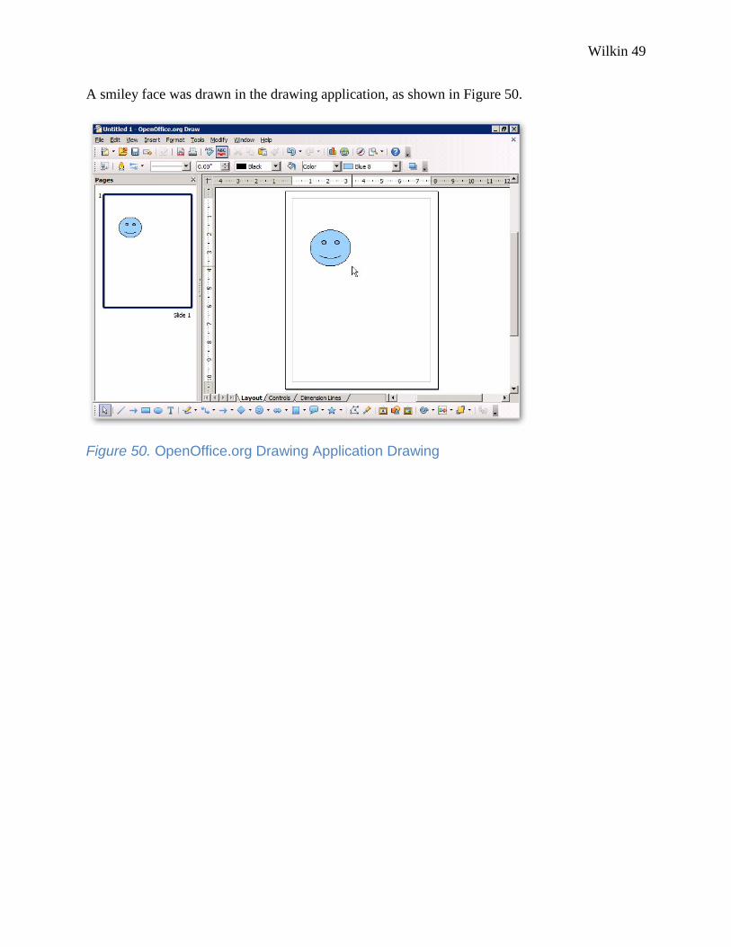
A smiley face was drawn in the drawing application, as shown in Figure 50.
Figure 50. OpenOffice.org Drawing Application Drawing

Wilkin 50
The drawing was then saved as “smile.odg” to the user’s documents folder, as shown in Figure
51.
Figure 51. Image Saved as “smile.odg”

Wilkin 51
On the TS-PG1 server the ‘smile.odg’ file was opened and viewed successfully as shown in
Figure 52.
Figure 52. Opening “smile.odg” on the Server

Wilkin 52
5.5 Network Access Protection
NAP requires a NPS to be setup and running in order to create and enforce health
policies. Health policies can include requiring a firewall, antivirus and Windows updates to be
installed and enabled on the client. If a client which is connecting to the network is non-
compliant with the health policies but is NAP capable, then remediation can be configured to
automatically correct the problem. This requires a second server to serve the remediation role.
Another possible scenario is that the client is either not NAP capable (i.e. Windows XP SP2 or
earlier) or cannot be remediated. In this case the client is not allowed full network access. Rather
it is given restricted access until the problem can be fixed.
To configure NAP on the network, first a NPS had to be created. In the NPS console the
NAP configuration scenario was selected and the “Configure NAP” option clicked, as shown in
Figure 53.
Figure 53. Network Policy Server Console

Wilkin 53
The network connection method selected was “DHCP” and a user friendly policy name was
entered as shown in Figure 54.
Figure 54. NAP Network Connection Method

Wilkin 54
In the NPS console, under NPS – Network Access Protection, “System Health Validators” was
selected as shown in Figure 55.
Figure 55. NAP System Health Validators

Wilkin 55
The Health Validator properties box appeared as shown in Figure 56. Configure was clicked to
open the configuration options for the Health Validator.
Figure 56. Health Validator Properties

Wilkin 56
As shown in Figure 57, under the Windows Vista tab the checkbox for “A firewall is enabled for
all network connections” was checked while all the other checkboxes were unchecked.
Figure 57. Setting the Health Validator to Require a Firewall
The next box which appeared was "Specify NAP Enforcement Servers Running DHCP Server".
This was left blank because the DHCP server was set to run on the same server as NPS.

Wilkin 57
At this stage, the next step was to configure DHCP for NAP. This was done via the DHCP
console by navigating to DHCP – nap-pg1.purplegoat.com – Ipv4, then right clicking on “Scope
[192.168.1.0]” and selecting “Properties”, as shown in Figure 58.
Figure 58. Configuring DHCP for NAP

Wilkin 58
“NAP Scope” was entered for Scope name. The starting IP address was set to 192.168.1.26 and
the end IP address was set to 192.168.1.60, as shown in Figure 59. The default lease duration of
six days was maintained.
Figure 59. Setting the NAP DHCP Scope and Name

Wilkin 59
Under the Network Access Protection tab, “Enable for this scope” and “Use default Network
Access Protection profile” were selected, as shown in Figure 60.
Figure 60. Enabling NAP for the DHCP Scope

Wilkin 60
When clients connect to the network, DHCP was used to assign each client a unique
private IP address. The default user class was applied and used for all NAP compliant clients.
This was done via the DHCP console by right clicking “Scope Options” under the IPv4 window
of “Scope [192.168.1.0]”, and then clicking “Configure Options”, as shown in Figure 61.
Figure 61. Configuring Scope Options

Wilkin 61
In the Scope Options under the “Advanced” tab, the vendor class was set to “DHCP
Standard Options” and “Default Class” for the user class. Under Available Options, “006 DNS
Servers” was checked and the DNS server IP address (192.168.1.20) was added, as shown in
Figure 62.
Figure 62. Setting the Default User Class DNS Server IP Address

Wilkin 62
In the same window, “015 DNS Domain Name” was checked under Available Options with a
string value of “purplegoat.com” entered as shown in Figure 63. These settings enabled NAP to
recognize the DNS server with an IP address of 192.168.1.20 and the domain name of
“purplegoat.com” as the setting to use for NAP compliant clients connecting to the network. This
gave the client full network access.
Figure 63. Configuring the DNS Name of the Default DNS Server

Wilkin 63
Noncompliant clients were assigned to a restricted access network. This was done by
adding an entry in DHCP for “restricted.purplegoat.com”. The vendor class remained “DHCP
Standard Options” but the user class was set to “Default Network Access Protection Class”. The
same IP address of 192.168.1.20 was used for “006 DNS Servers” as shown in Figure 64.
Figure 64. Configuring the Default NAP Class DNS Server IP Address

Wilkin 64
The string value for “015 DNS Domain Name” was set to “restricted.purplegoat.com”, as
shown in Figure 65.
Figure 65. Configuring the DNS Name of the DNS Server for the Restricted Network
The restricted.purplegoat.com was the restricted access network set up for NAP non-compliant
and non-capable clients to be assigned to.
In order for NAP to be fully functional it had to be configured on the server as well as the
client. There was a NAP service which ran on the client called the “Network Access Protection
Agent”. The NAP agent service was set to run automatically on Vista machines. Also the
“Enforcement Client” had to be enabled. This was done by opening the NAP client configuration
console and then executing ‘napclcfg.msc’ at the run prompt.

Wilkin 65
The “DHCP Quarantine Enforcement Client” was enabled on the client machine as
shown in Figure 66.
Figure 66. NAP Client Configuration Console

Wilkin 66
Executing “netsh nap client show state” from the command line interface verified that the
NAP client service was running and that the DHCP Quarantine Enforcement Client was enabled,
as shown in Figure 67.
Figure 67. Verifying the NAP Client Configuration
Executing ipconfig on the client showed that it was logged onto the purplegoat.com network
with a valid IP address of 192.168.1.29 on the network, as shown in Figure 68. Ipconfig also
showed the subnet mask of 255.255.255.0, which was the network of the purplegoat.com
domain.
Figure 68. Verifying the IP Address assigned to the Client

Wilkin 67
This indicated that this client was compliant with NAP health policies which were set to require
that the client was NAP capable and that the firewall on the client was enabled. Comparing
Figure 68 with Figure 67 shows that the NAP client service was running which means it is NAP
capable.
If a NAP-capable client connects to the network with the firewall disabled or the firewall
is disabled after it is connected to the network, NAP will detect this situation and remediate the
problem by automatically enabling the firewall on the client. Figure 69 displays the resulting
NAP server log when the firewall was disabled on VISTA02.
Figure 69. NAP Server Log – Client with Firewall Disabled

Wilkin 68
The log details show that VISTA02 was quarantined due to failing to be NAP DHCP Compliant.
The remediation took place when NAP automatically enabled the firewall on VISTA02. Figure
70 shows the NAP log which indicates that the client was compliant with NAP DHCP. The client
was removed from the restricted network (quarantine)”restricted.purplegoat.com”, and was given
full access to purplegoat.com.
Figure 70. After Remediation the Client Is Granted Full Access to the Network
If the client were not NAP capable, it would have been assigned to the restricted network
(restricted.purplegoat.com). This was achievable by disabling the “Network Access Protection
Agent” service on VISTA02, and then renewing the DHCP IP address. The
restricted.purplegoat.com domain included DC-PG1 and NAP-PG1. However, TS-PG1 was not
included. Therefore VISTA02 could ping TS-PG1 only when given full access by NAP. If

Wilkin 69
VISTA02 was on the restricted network, it would not have been able to ping TS-PG1. The ping
result when VISTA02 had full access to the network was successful, as shown in Figure 71.
Since the ping request was successful and there was 0% packet loss, it verified that the VISTA02
client could communicate with TS-PG1.
Figure 71. Pinging 192.168.1.22 (TS-PG1) from VISTA02
The result of the ping with the “Network Access Protection Agent” service disabled on VISTA02
was unsuccessful as shown in Figure 72. Since the ping request failed with 100% packet loss it
verified that VISTA02 could not communicate with TS-PG1.
Figure 72. Unsuccessful Ping Results from the Client to TS-PG1
To verify if the NPA agent service was running, “netsh nap client show state” was run from the
command line interface which indicates it was not running, as shown in Figure 73.
Figure 73. Verifying that the NAP Agent Is not Running on the Client

Wilkin 70
VISTA02 was on the restricted network since the NAP agent had been disabled, thus rendering it
NAP non-capable. Running ipconfig on VISTA02 resulted in a valid IP address; however, it also
indicated that it was assigned to the restricted.purplegoat.com network as shown in Figure 74.
Figure 74. Ipconfig Run on VISTA02 Indicates it is on the Restricted Network

Wilkin 71
6. Timeline
Table 4 shows the timeline the entire project.
ID Task Name Start Finish2008 2009
Oct Nov Dec Jan Feb Mar Apr May
1 10/24/20089/24/2008Research
2 12/4/200810/13/2008Write Proposal
3 11/24/200811/24/2008Present Proposal
4 1/12/20091/5/2009Set Up Windows Server 2008
1/20/20091/20/2009List of Deliverables
1/26/20091/14/2009Configure Virtual Servers in Hyper-V
5
6
11
10
9
8
7 1/26/20091/26/2009Updated Project Budget and Risk Analysis Plan
2/18/20091/26/2009Configure TS RemoteApp
2/16/20092/16/2009Design Freeze – First Draft
2/24/20092/18/2009Configure Firewall
3/2/20093/2/2009Present Final Prototype
3/11/20093/11/2009Design Freeze – Final Draft12
18
17
16
15
14 4/1/20093/11/2009Configure NAP
4/1/20093/11/2009Screenshots of Procedures13
5/29/20094/1/2009Final Report
5/1/20095/1/2009Present Project
5/7/20095/7/2009Tech Expo
6/2/20096/2/2009Final Report – Signed and Bound
Table 4. Project Timeline
The first phase of the project consisted of research for the project and creating a
proposal. The proposal was presented at the University of Cincinnati. The second phase
was dedicated to starting the actual building of the prototype as well as creating a list of
deliverables. These items made up the design freeze which was presented to the
University. The third phase involved finalizing the prototype to meet the deliverables.
The project was presented at Tech Expo as well as at the University. The report was
finalized and published.

Wilkin 72
7. Budget
The budget for this project is shown in Table 5. The total retail cost of the project was
$5,410.00. Over half of the cost was covered by the Microsoft Academic Alliance and Skipjack
Financial Services (for the laptop). The out-of-pocket cost was $2,014.00, which covered the
project server, desktop, and external backup hard drive.
Item Description Retail Cost My Cost
Dell PowerEdge T105 Project server to host all virtual machines $1,130.00 $1,130.00
Desktop Desktop used for accessing server 800 800
Laptop Laptop used for accessing server 1400 0
Western Digital Hard Drive Hard drive used for backups 84 84
Windows Server 2008 Provided by Academic Alliance 1000 0
Windows Server 2003 Provided by Academic Alliance 1000 0
Total $5,410 $2,014
Table 5. Project Budget (2, 13)

Wilkin 73
8. Deliverables
The Hyper-V role was enabled on host server. The primary role of the host server was to
host the virtual machines which made up the network for implementing the other deliverables.
Hyper-V successfully fulfilled this role. In addition, the external backup drive was connected to
this server and Windows Server Backup used to back up the entire project including the host
server and virtual machines.
Three virtual servers were created: the domain controller, the NAP server and the TS
server. All three ran Windows Server 2008 Standard edition. The domain controller ran DNS,
provided the Active Directory service and also provided the remediation role for NAP. Windows
Advanced Firewall was enabled and demonstrated on the domain controller.
A virtual server dedicated to the NAP implementation of a Dynamic Host Configuration
Protocol (DHCP) was created and implemented. Clients were required to have Windows
Firewall enabled in order to gain full network access.
TS RemoteApp was configured using the TS Web Access method and Open Office.org as
the software. Clients were able to utilize TS RemoteApp to run OpenOffice.org and create and
save documents.
Windows Server 2008 Advanced firewall was enabled and configured on domain
controller. Custom advanced firewall rules were configured to limit outbound traffic
9. Testing Plan
This project was tested by the author. Reliance on logs on the servers themselves verified
the results of the implementation. The manager at Skipjack Financial Services, a Microsoft
Certified Systems Engineer, reviewed the deliverables and confirmed they were met. Testing
helped ensure that the features implemented were operating properly and as designed. Testing

Wilkin 74
also served to get feedback, which was helpful in improving the project. Testing of Hyper-V
functionality was done via the Hyper-V console on the host server. Functions tested included
creating virtual servers, controlling virtual server status, and creating snapshots of virtual servers.
Testing of TS RemoteApp involved connecting a Vista client to the TS RemoteApp service on
the server in order to access the desired applications. A check was done to ensure that the client
machine could access applications and execute them successfully via the desktop. Conversely,
tests were conducted to see if clients without permissions could access applications on the server.
The Windows 2008 Firewall was tested similarly, except that what was being tested was
blocking of outbound traffic. Logging showed details which helped determine if the firewall
rules were being applied correctly. NAP was set up to require that a firewall be enabled on the
client. A NAP Health Policy Server was set up and added to the network. Testing the connection
to the network from the client side was either allowed or prohibited, depending on the client state
and the NAP settings. On the server side, logs showed the result of a client which was either
permitted or denied to access the network.
10. Risk Management Plan
Some risks to the project were successfully mitigated, as shown in Table 6. Hyper-V
requires a processor that supports virtualization in order to function properly. For this reason, the
Dell PowerEdge T105 with AMD Opteron Quad Core 1352 Processor was selected for use as the
host server. Using the snapshot feature allowed any problematic changes to be undone, in a sense
rolling it back. The virtual machines were backed up on the external hard drive so if the server
failed, the virtual machines could be restored once the server was fixed. Functionality was a key
part of the presentation, and for this purpose a live demonstration was used. However, since a

Wilkin 75
free, unguaranteed dynamic DNS service was being used, videos using CamStudio software were
created for the presentation.
Risk Description Risk Level Risk Mitigation Plan
Change to servers causes problems High Use the snapshot feature of Hyper-V
Hyper-V does not work on server High Spec out server hardware to meet Hyper-V
requirements
Project server crashes and burns High Backups on external hard drive
Detailed notes on configuration
Utilize Dell warranty
Remote connection to not available High Videos of what will be presented as a backup
Test remote connection often
Table 6. Project Risks
11. Conclusion
Microsoft Windows Server 2008 offers many new features that are designed to make
businesses more secure and productive. This project explored a number of these new features:
Hyper-V, NAP, TS RemoteApp and Server 2008 Firewall. In the not-so-distant future, many
companies will consider upgrading their servers’ infrastructures in order to meet security
demands and the changes in the way server technology is used in the workplace. This project
demonstrated the key features which those businesses will regard as important.
Systems administrators working with Windows Server 2008 can reference this document
for the technical content. They can use it to implement their own network infrastructure.
Information Technology managers can reference this document in order to get a better
understanding of the key new features of Server 2008.

Wilkin 76
References
1. Davies, Joseph, and Tony Northrup. Windows Server 2008 Networking and Network
Access Protection (NAP). New York: Microsoft Press, 2008.
2. Dell Inc. 2008. 30 Nov. 2008 <http://www.dell.com>.
3. Holme, Dan, Dan Ruest, and Danielle Ruest. MCTS Self-Paced Training Kit (Exam 70-
640): Configuring Windows Server 2008 Active Directory. Redmond: Microsoft Press,
May 5, 2008.
4. Johansson, Jesper M. Windows Server 2008 Security Resource Kit (PRO - Resource Kit)
(PRO - Resource Kit). New York: Microsoft P, 2008.
5. Mackin, J. C., and Anil Desai. MCTS Self-Paced Training Kit (Exam 70-643):
Configuring Windows Server 2008 Application Platform. New York: Microsoft P,
2008.
6. Russel, Charlie, and Sharon Crawford. Windows Server 2008 Administrator's
Companion. Redmond: Microsoft Press, April 19, 2008.
7. Morimoto, Rand, Michael Noel, Omar Droubi, Ross Mistry, and Chris Amaris. Windows
Server 2008 Unleashed. Indianapolis: Sams, 2008.

Wilkin 77
8. Morimoto, Rand, and Jeff Guillet. Windows Server 2008 Hyper-V Unleashed.
Indianapolis: Sams, 2008.
9. Shinder, Debra Littlejohn. "10 Things to Consider when Making a Windows Server 2008
Upgrade Decision." CNET Networks. October 15, 2008
<http://blogs.techrepublic.com.com/10things/?p=269>.
10. Shinder, Dr. Tom. "Introducing Windows Server 2008: Top 10 Reasons to Upgrade".
WindowsNetworking.com. October 15, 2008
<http://www.windowsnetworking.com/articles_tutorials/Windows-Server-2008-Top-
10-Reasons-Upgrade.html>.
11. Stanek, William R. Windows Server 2008 Administrator's Pocket Consultant (Pro -
Administrator's Pocket Consultant). New York: Microsoft Press, 2008.
12. Stanek, William R. Windows Server 2008 Inside Out. New York: Microsoft Press, 2008.
13. Windows Server 2008 Pricing. 2008. Microsoft. 30 Nov. 2008
<http://www.microsoft.com/windowsserver2008/en/us/pricing.aspx>.