microprocessor supervisory circuit - maxim integrated · max791 microprocessor supervisory circuit...
TRANSCRIPT

MA
X7
91
Microprocessor Supervisory Circuit
________________________________________________________________ Maxim Integrated Products 1
19-0075; Rev. 7; 11/05
General DescriptionThe MAX791 microprocessor (µP) supervisory circuitreduces the complexity and number of components need-ed to monitor power-supply and battery-control functionsin µP systems. The 50µA supply current makes theMAX791 ideal for use in portable equipment, while the 6nschip-enable propagation delay and 250mA output capa-bility (25mA in battery-backup mode) make it suitable forlarger, higher-performance equipment.The MAX791 comes in 16-pin DIP, TSSOP, and narrow SOpackages and provides the following functions:• µP reset.
–R—E—S—E—T–
output is asserted during power-up,power-down, and brownout conditions, and is guaran-teed to be in the correct state for VCC down to 1V, even with no battery in the circuit.
• Manual-reset input.• A 1.25V threshold detector provides for power-fail
warning and low-battery detection, or monitors apower supply other than +5V.
• Two-stage power-fail warning. A separate low-linecomparator compares VCC to a threshold 150mVabove the reset threshold.
• Backup-battery switchover for CMOS RAM, real-timeclocks, µPs, or other low-power logic.
• Software monitoring of backup-battery voltage.• A watchdog-fault output is asserted if the watchdog
input has not been toggled within either a preset oran adjustable timeout period.
• Write protection of CMOS RAM or EEPROM.• Pulsed watchdog output to give advance warning of
impending–W—D—O–
assertion caused by watchdog timeout.
ApplicationsComputers Critical µP Power MonitoringControllers Intelligent InstrumentsPortable/Battery-Powered Equipment
Features♦ Precision 4.65V Voltage Monitoring♦ 200ms Power-OK/Reset Time Delay♦ Independent Watchdog Timer—Preset or Adjustable♦ 1µA Standby Current♦ Power Switching
250mA Output in VCC Mode25mA Output in Battery-Backup Mode
♦ On-Board Gating of Chip-Enable SignalsMemory Write-Cycle Completion6ns CE Gate Propagation Delay
♦ MaxCap or SuperCap Compatible♦ Voltage Monitor for Power-Fail or Low-Battery Warning♦ Backup-Battery Monitor♦ Guaranteed
–R—E—S—E—T–
Valid to VCC = 1V
Ordering Information
16
15
14
13
12
11
10
9
1
2
3
4
5
6
7
8
WDPO
RESET
WDO
CE INGND
VCC
VOUT
VBATTTOP VIEW
MAX791
CE OUT
WDI
LOWLINE
MRSWT
PFI
PFO
BATT ON
DIP/SO/TSSOP
CMOSRAM
MAX791
RESET
LOWLINE
WDI
CE IN
CE OUT
+5V
OTHER SYSTEMRESET SOURCES
+12V
VOUTVBATT
*MaxCap
A0–A15
MR
+12V SUPPLY
FAILURE
BATTON
SWT
ADDRESSDECODE
0.1µF0.1µF
0.47F*VCC
PFI
PFO
GND
I/OµP
NMI
INTRESET
WDO
Pin Configuration
Typical Operating Circuit
PART TEMP RANGE PIN-PACKAGE
MAX791CPE 0°C to +70°C 16 Plastic DIP
MAX791CSE 0°C to +70°C 16 Narrow SO
MAX791C/D 0°C to +70°C Dice*
MAX791EPE -40°C to +85°C 16 Plastic DIP
MAX791ESE -40°C to +85°C 16 Narrow SO
MAX791EJE -40°C to +85°C 16 CERDIP
MAX791MJE -55°C to +125°C 16 CERDIP
MaxCap is a registered trademark of Cesiwid Inc. SuperCap is a registered trademark of Baknor Industries.
* Dice are specified at TA = +25°C.Devices in PDIP, SO and TSSOP packages are available in bothleaded and lead-free packaging. Specify lead free by addingthe + symbol at the end of the part number when ordering.Lead free not available for CERDIP package.
MAX791CUE 0°C to +70°C 16 TSSOP
MAX791EUE -40°C to +85°C 16 TSSOP
For pricing, delivery, and ordering information, please contact Maxim/Dallas Direct! at 1-888-629-4642, or visit Maxim’s website at www.maxim-ic.com.

MA
X7
91
Microprocessor Supervisory Circuit
2 _______________________________________________________________________________________
Input Voltage (with respect to GND)VCC.......................................................................-0.3V to +6VVBATT..................................................................-0.3V to + 6VAll Other Inputs.....................................-0.3V to (VOUT + 0.3V)
Input CurrentVCC Peak ..........................................................................1.0AVCC Continuous ............................................................250mAVBATT Peak ..................................................................250mAVBATT Continuous ..........................................................25mAGND, BATT ON.............................................................100mAAll Other Outputs ............................................................25mA
Continuous Power Dissipation (TA = +70°C)Plastic DIP (derate 10.53mW/°C above +70°C) ..........842mWNarrow SO (derate 8.70mW/°C above +70°C) ............696mWCERDIP (derate 10.00mW/°C above +70°C)...............800mWTSSOP (derate 6.70mW/°C above +70°C) ..................533mW
Operating Temperature RangesMAX791C_ _ ......................................................O°C to +70°CMAX791E_ _ ....................................................-40°C to +85°CMAX791MJE ..................................................-55°C to +125°C
Storage Temperature Range .............................-65°C to +160°CLead Temperature (soldering, 10s) .................................+300°C
ELECTRICAL CHARACTERISTICS(VCC = 4.75V to 5.5V, VBATT = 2.8V, TA = TMIN to TMAX, unless otherwise noted.)
Stresses beyond those listed under “Absolute Maximum Ratings” may cause permanent damage to the device. These are stress ratings only, and functionaloperation of the device at these or any other conditions beyond those indicated in the operational sections of the specifications is not implied. Exposure toabsolute maximum rating conditions for extended periods may affect device reliability.
ABSOLUTE MAXIMUM RATINGS
PARAMETER CONDITIONS
Supply Current in Battery-BackupMode (excludes IOUT) (Note 2)
MIN TYP MAX UNITS
VBATT = 4.5V, IOUT = 20mA VBATT - 0.3
Operating Voltage RangeVCC, VBATT (Note 1)
0 5.5 V
VCC - 0.3 VCC - 0.2
VCC - 0.05 VCC - 0.02
VBATT-to-VOUT On-Resistance
5
VBATT = 2.0V
µA
17 30
Ω
Battery-Switchover ThresholdPower down VBATT - 0.03
V
VOUT in NormalOperating Mode
VCC = 3V, VBATT = 2.8V, IOUT = 100mA VCC - 0.2 VCC - 0.12
V
VCC = 4.5V0.8 1.6
0.8 1.2
VCC = 4.5V
VCC - 0.40
VBATT = 2.8V, IOUT = 10mA VBATT - 0.25
0.04 1
Supply Current in NormalOperating Mode (excludes IOUT)
VCC > VBATT - 1V 50 150 µA
VCC-to-VOUT On-Resistance
VCC = 3V 1.2 2.0
Ω
VBATT = 4.5V 8 15
VBATT = 2.8V
Power up
13 25
VBATT + 0.03
VOUT in Battery-Backup Mode
VBATT = 2.0V, IOUT = 5mA VBATT - 0.15
V
Battery-Switchover Hysteresis 60 mV
Low-Battery Detector Threshold 2 V
IOUT = 250mA
IOUT = 25mA
MAX791C/E
MAX791M
MAX791C/E
MAX791M
VCC < VBATT - 1.2V,VBATT = 2.8V
TA = +25°C
TA = TMIN to TMAX
VBATT Standby Current(Note 3) TA = TMIN to TMAX
TA = +25°C
-1.0 0.02µAVBATT + 0.2V ≤ VCC
-0.1 0.02

ns
MA
X7
91
Microprocessor Supervisory Circuit
_______________________________________________________________________________________ 3
ELECTRICAL CHARACTERISTICS (continued)(VCC = 4.75V to 5.5V, VBATT = 2.8V, TA = TMIN to TMAX, unless otherwise noted.)
0.7 1.5ISINK = 25mA
mA7 20Output source current–W—D—P—O–
Output Short-Circuit Current
V0.1 0.4ISINK = 3.2mABATT ON Output
Low Voltage
ms104.7nF capacitor connected from SWT to GNDMinimum WatchdogTimeout Period
ms1–W—D—P—O–
Pulse Width
ns100VIL = 0.8V, VIH = 0.75 x VCCMinimum Watchdog InputPulse Width
µs80Power downVCC-to-–L—O—W— —L—I—N—E–
Delay
s1.0 1.6 2.25SWT connected to VOUT
V4.50 4.65 4.75–R—E—S—E—T–
Threshold Voltage
mV150–L—O—W— —L—I—N—E–-to-
–R—E—S—E—T–
Threshold Voltage
µs100Power downVCC-to-–R—E—S—E—T–
Delay
mV15–R—E—S—E—T–
Threshold Hysteresis
Watchdog Timeout Period
ns70–W—D—P—O–-to-–W—D—O– Delay
µA
ms
1 15 100Source currentBATT ON OutputShort-Circuit Current
mA60Sink current
140 200 280Power up
UNITSMIN TYP MAX
–R—E—S—E—T–
Active Timeout Period
CONDITIONSPARAMETER
0.004 0.3MAX791E/M, ISINK = 50µA, VCC = 1.2V, VCC falling
0.1 0.4ISINK = 3.2mA, VCC = 4.25VV
3.5ISOURCE = 1.6mA, VCC = 5V
–R—E—S—E—T–
Output Voltage
mA7 20Output source current–R—E—S—E—T–
Output Short-Circuit Current
0.4ISINK = 3.2mA, VCC = 4.25V
µA15 100Output source current–L—O—W— —L—I—N—E–
Output Short-Circuit Current
V3.5ISOURCE = 1µA, VCC = 5V
–L—O—W— —L—I—N—E–
Output Voltage
0.4ISINK = 3.2mA
mA3 10Output source current–W—D—O–
Output Short-Circuit Current
V3.5ISOURCE = 500µA, VCC = 5V
–W—D—O–
Output Voltage
0.4ISINK = 3.2mAV
3.5ISOURCE = 1mA–W—D—P—O–
Output Voltage
0.004 0.3MAX791C, ISINK = 50µA, VCC = 1.0V, VCC falling
RESET, LOW-LINE, AND WATCHDOG TIMER

MA
X7
91
Microprocessor Supervisory Circuit
4 _______________________________________________________________________________________
ELECTRICAL CHARACTERISTICS (continued)(VCC = 4.75V to 5.5V, VBATT = 2.8V, TA = TMIN to TMAX, unless otherwise noted.)
Note 1: Either VCC or VBATT can go to 0V, if the other is greater than 2.0V.Note 2: The supply current drawn by the MAX791 from the battery (excluding IOUT) typically goes to 10µA when
(VBATT - 1V) < VCC < VBATT. In most applications, this is a brief period as VCC falls through this region.Note 3: "+" = battery-discharging current, "-" = battery-charging current.Note 4: WDI is internally connected to a voltage-divider between VOUT and GND. If unconnected, WDI is driven to 1.6V (typ),
disabling the watchdog function.Note 5: The chip-enable resistance is tested with VCC = 4.75V V –C—E
–IN = V C—E
–OUT = VCC / 2.
Note 6: The chip-enable propagation delay is measured from the 50% point at –C—E– IN to the 50% point at –C—E– OUT.
ns6 1050Ω source impedance driver, CLOAD = 50pF–C—E– IN-to-C—E– OUT PropagationDelay (Note 6)
-50 -10WDI = 0VµA
20 50WDI = VOUTWDI Input Current
0.75 x VCCVIH
µA23 250–M—R– = 0V–M—R– Pull-Up Current
µs7
Ω75 150Enabled mode
–M—R–-to -–R—E—S—E—T–
Propagation Delay
–C—E– IN-to-–C—E– OUT Resistance(Note 5)
µA±0.005 ±1Disabled mode–C—E– IN Leakage Current
µs15Power down–R—E—S—E—T–-to-–C—E– OUT Delay
nA±0.01 ±25PFI Leakage Current
V1.25VCC = 5V–M—R– Threshold
mA0.1 0.75 2.0
µs
Disabled mode, –C—E– OUT = 0V
25 15
–C—E– OUT Short-Circuit Current(Reset Active)
V1.20 1.25 1.30VCC = 5VPFI Input Threshold
V0.8VIL
WDI Threshold Voltage(Note 4)
UNITSMIN TYP MAX
–M—R– Minimum Pulse Width
CONDITIONSPARAMETER
0.4ISINK = 3.2mAV
3.5ISOURCE = 1µA, VCC = 5V–P—F—O–
Output Voltage
mA60Output sink current
µA1 15 100Output source current–P—F—O–
Short-Circuit Current
µs55VIN = 20mV, VOD = 15mV
PFI-to-–P—F—O–
Delay15VIN = -20mV, VOD = 15mV
3.5VCC = 5V, IOUT = -100µAV
2.7VCC = 0V, VBATT = 2.8V, IOUT = 1µA
–C—E– OUT Output Voltage High(Reset Active)
POWER-FAIL COMPARATOR
CHIP-ENABLE GATING
MANUAL RESET INPUT

MA
X7
91
Microprocessor Supervisory Circuit
58
38-60 -30 30 150
VCC SUPPLY CURRENT vs. TEMPERATURE(NORMAL OPERATING MODE)
42
54
MAX
791-
01
TEMPERATURE (°C)
V CC
SUPP
LY C
URRE
NT (µ
A)
0 1209060
46
50
VCC = +5VVBATT = 2.8VPFI, CE IN = 0V
4.80
4.30
4.40
4.35
-60 -30 30 150
RESET THRESHOLDvs. TEMPERATURE
MAX
791-
07
TEMPERATURE (°C)
RESE
T TH
RESH
OLD
(V)
0 1209060
4.45
4.50
4.55
4.60
4.65
4.70
4.75
VBATT = 0V,POWER DOWN
600
0
100
-60 -30 30 150
RESET OUTPUT RESISTANCEvs. TEMPERATURE
MAX
791-
08
TEMPERATURE (°C)
RESE
T OU
TPUT
RES
ISTA
NCE
(Ω)
0 1209060
200
300
400
500
VCC = 0V, VBATT = 2.8VSINKING CURRENT
VCC = +5V, VBATT = 2.8VSOURCING CURRENT
230
170
180
-60 -30 30 150
RESET DELAYvs. TEMPERATURE
MAX
791-
09
TEMPERATURE (°C)
RESE
T DE
LAY
(ms)
0 1209060
190
200
210
220
VCC = 0V TO 5V STEPVBATT = 2.8V
Typical Operating Characteristics(TA = +25°C, unless otherwise noted.)
20
5-60 -30 30 150
VBATT-to-VOUT ON-RESISTANCEvs. TEMPERATURE
MAX
791-
04
TEMPERATURE (°C)
VBAT
T-to
-VOU
T ON-
RESI
STAN
CE (
Ω)
0 1209060
10
15
VBATT = 2.0V
VBATT = 2.8V
VBATT = 4.5V
VCC = 0V
2.0
0-60 -30 30 150
BATTERY-SUPPLY CURRENT vs. TEMPERATURE(BATTERY-BACKUP MODE)
0.5
MAX
791-
02
TEMPERATURE (°C)
BATT
ERY
SUPP
LY C
URRE
NT (µ
A)
0 1209060
1.0
1.5
VCC = 0VVBATT = 2.8VNO LOAD
120
40-60 -30 30 150 180
CHIP-ENABLE ON-RESISTANCEvs. TEMPERATURE
60
MAX
791-
03
TEMPERATURE (°C)
CE O
N-RE
SIST
ANCE
(Ω
)
0 1209060
80
100
VCC = +4.75VVBATT = 2.8VCE IN = VCC/2
1.2
0.6
0.7
-60 -30 30 150
VCC-to-VOUT ON-RESISTANCEvs. TEMPERATURE
MAX
791-
05
TEMPERATURE (°C)
V CC-
to-V
OUT
ON-R
ESIS
TANC
E (Ω
)
0 1209060
0.8
0.9
1.0
1.1
VCC = +5V,VBATT = 0V
1.50
0
0.25
-60 -30 30 150
PFI THRESHOLDvs. TEMPERATURE
MAX
791-
05
TEMPERATURE (°C)
PFI T
HRES
HOLD
(V)
0 1209060
0.50
0.75
1.00
1.25
VCC = +5V,VBATT = 0V,NO LOAD ON PFO
_______________________________________________________________________________________ 5

MA
X7
91
Microprocessor Supervisory Circuit
6 _______________________________________________________________________________________
Typical Operating Characteristics (continued)(TA = +25°C, unless otherwise noted.)
1000
11 100 1000
VCC to VOUT vs.OUTPUT CURRENT
10
100
MAX
791-
13
IOUT (mA)
V CC
- VOU
T (m
V)
10
VCC = 4.5VVBATT = 0V
SLOPE = 0.8Ω
1000
11 10 100
VBATT to VOUT vs.OUTPUT CURRENT
MAX
791-
14
IOUT (mA)
VBAT
T - V
OUT
(mV)
10
100
VCC = 0VVBATT = 4.5V
SLOPE = 8Ω
0
50
0 4020
WATCHDOG TIMEOUTvs. TIMING CAPACITOR
MAX
791-
11
TIMING CAPACITOR (nF)
WAT
CHDO
G TI
MEO
UT (m
s)
3010 70 80 90 1006050
100
150
200
250
VCC = +5VVBATT = 2.8V
0
4
0 10050
CHIP-ENABLE PROPAGATION DELAYvs. CE OUT LOAD CAPACITANCE
MAX
791-
12
CLOAD (pF)
PROP
AGAT
ION
DELA
Y (n
s)
200 250 300150
8
12
16
20
VCC = +5VCE IN = 0V TO 5VDRIVER SOURCEIMPEDANCE = 50Ω
0
4
8
1 5
BATTERY CURRENTvs. INPUT SUPPLY VOLTAGE
MAX
791-
10
VCC (V)
I BAT
T (µA
)
0 432
12
16
20
VBATT = 2.8V,IOUT = 0A

MA
X7
91
Microprocessor Supervisory Circuit
_______________________________________________________________________________________ 7
Pin DescriptionPIN NAME FUNCTION
1 VBATT
2 VOUT
Output Supply Voltage. VOUT connects to VCC when VCC is greater than VBATT and VCC is above the resetthreshold. When VCC falls below VBATT and VCC is below the reset threshold, VOUT connects to VBATT.Connect a 0.1µF capacitor from VOUT to GND.
3 VCC Input Supply Voltage—+5V input
4 GND
5 BATT ON
6–P—F—O–
7 PFI
8 SWT
9 –M—R–
10–L—O—W— —L—I—N—E–
11 WDI
12 –C—E– OUTChip-Enable Output. –C—E– OUT goes low only when ––C—E– IN is low and VCC is above the reset threshold. If –C—E– IN islow when reset is asserted, –C—E– OUT will stay low for 15µs or until –C—E– IN goes high, whichever occurs first.
13 ––C—E– IN
Backup-Battery Input. Connect to external battery or capacitor and charging circuit.
Ground. 0V reference for all signals.
Battery-On Output. Goes high when VOUT switches to VBATT. Goes low when VOUT switches to VCC. Connectthe base of a PNP through a current-limiting resistor to BATT ON for VOUT current requirements greater than250mA.
Power-Fail Output. This is the output of the power-fail comparator. –P—F—O–
goes low when PFI is less than 1.25V.This is an uncommitted comparator, and has no effect on any other internal circuitry.
Power-Fail Input. This is the noninverting input to the power-fail comparator. When PFI is less than 1.25V,–P—F—O–
goes low. Connect PFI to GND or VOUT when not used.
Set Watchdog-Timeout Input. Connect this input to VOUT to select the default 1.6s watchdog-timeout period.Connect a capacitor between this input and GND to select another watchdog-timeout period. Watchdog-timeoutperiod = 2.1 x (capacitor value in nF) ms.
16–W—D—P—O–
15–R—E—S—E—T–
14–W—D—O–
Manual-Reset Input. This input can be tied to an external momentary pushbutton switch, or to a logic gate out-put.
–R—E—S—E—T–
remains low as long as –M—R– is held low and for 200ms after –M—R– returns high.
–L—O—W— —L—I—N—E–
Output goes low when VCC falls to 150mV above the reset threshold. The output can be used to gen-erate an NMI if the unregulated supply is inaccessible.
Watchdog Input. WDI is a three-level input. If WDI remains either high or low for longer than the watchdog time-out period,
–W—D—O–
goes low. –W—D—O–
remains low until the next transition at WDI. Leaving WDI unconnected disablesthe watchdog function. WDI connects to an internal voltage-divider between VOUT and GND, which sets it to mid-supply when left unconnected.
Chip-Enable Input. The input to chip-enable gating circuit. Connect to GND or VOUT if not used.
Watchdog Output. –W—D—O–
goes low if WDI remains either high or low longer than the watchdog-timeout period. –W—D—O–
returns high on the next transition at WDI. –W—D—O–
remains high if WDI is unconnected. –W—D—O–
is also highwhen
–R—E—S—E—T–
is asserted.
–R—E—S—E—T–
Output goes low whenever VCC falls below the reset threshold. –R—E—S—E—T–
will remain low for typically 200msafter VCC crosses the reset threshold on power-up.
Watchdog-Pulse Output. Upon the absence of a transition at WDI, –W—D—P—O–
will pulse low for a minimum of 1ms.–W—D—P—O–
precedes ––W—D—O–
by 70ns.

_______________Detailed Description
Manual Reset InputMany µP-based products require manual-reset capabil-ity, allowing the operator or test technician to initiate areset. The Manual Reset Input (MR) can be connecteddirectly to a switch, without an external pull-up resistoror debouncing network. It connects to a 1.25V com-parator, and has a pull-up to VOUT as shown in Figure1. The propagation delay from asserting MR to RESETasserted is 4µs typ. Pulsing MR low for a minimum of15µs resets all the internal counters, sets the WatchdogOutput (WDO) and Watchdog-Pulse Output (WDPO)
high, and sets the Set Watchdog-Timeout (SWT) inputto VOUT - 0.6V, if it is not already connected to VOUT(for internal timeouts). It also disables the chip-enablefunction, setting the Chip-Enable Output (CE OUT) to ahigh state. The RESET output remains active as long asMR is held low, and the reset-timeout period beginsafter MR returns high (Figure 2).
Use this input as either a digital-logic input or a secondlow-line comparator. Normal TTL/CMOS levels can bewire-OR connected via pull-down diodes (Figure 3),and open-drain/collector outputs can be wire-OReddirectly.
MA
X7
91
Microprocessor Supervisory Circuit
8 _______________________________________________________________________________________
MAX791
CHIP-ENABLEOUTPUT
CONTROL
VCC 3
1
13
9
8
11
7
VBATT
CE IN
MR
SWT
WDI
PFI
RESETGENERATION
TIMEBASE FORRESET ANDWATCHDOG
WATCHDOGTRANSITIONDETECTOR
WATCHDOGTIMER
VOUT
1.25V
GND4
4.65V150mV
10
LOWLINE
5
2
12
15
16
14
PFO
WDO
WDPO
RESET
CE OUT
6
VOUT
BATT ON
Figure 1. MAX791 Block Diagram
MR
RESET
CE IN0V
7.5µs TYP
15µs TYP
25µs MIN
CE OUT
Figure 2. Manual-Reset Timing Diagram
MAX791*
*
OTHER RESET
SOURCES
MANUAL RESET
MR
* DIODES NOT REQUIRED ON OPEN-DRAIN OUTPUTS
Figure 3. Diode "OR" Connections Allow Multiple Reset Sourcesto Connect to MR

RESET OutputThe MAX791’s RESET output ensures that the µP pow-ers up in a known state, and prevents code-executionerrors during power-down or brownout conditions.
The RESET output is active low, and typically sinks3.2mA at 0.1V saturation voltage in its active state.When deasserted, RESET sources 1.6mA at typicallyVOUT - 0.5V. When no backup battery is used, RESEToutput is guaranteed to be valid down to VCC = 1V, andan external 10kΩ pull-down resistor on RESET ensuresthat RESET will be valid with VCC down to GND (Figure4). As VCC goes below 1V, the gate drive to the RESEToutput switch reduces accordingly, increasing therDS(ON) and the saturation voltage. The 10kΩ pull-downresistor ensures the parallel combination of switch plusresistor is around 10kΩ and the output saturation volt-age is below 0.4V while sinking 40µA. When using a10kΩ external pull-down resistor, the high state for theRESET output with VCC = 4.75V is 4.5V typ. For batteryvoltages ≥ 2V connected to VBATT, RESET remainsvalid for VCC from 0V to 5.5V.
RESET will be asserted during the following conditions:
• VCC < 4.65V (typ).
• MR < 1.25V (typ).
• RESET remains asserted for 200ms (typ) after VCCrises above 4.65V or after MR has exceeded 1.25V.
The MAX791 battery-switchover comparator does notaffect RESET assertion. However, RESET is asserted inbattery-backup mode since VCC must be below thereset threshold to enter this mode.
Watchdog FunctionThe watchdog monitors µP activity via the WatchdogInput (WDI). If the µP becomes inactive, WDO andWDPO are asserted. To use the watchdog function,connect WDI to a bus line or µP I/O line. If WDI remains
high or low for longer than the watchdog timeout period(1.6s nominal), WDPO and WDO are asserted, indicat-ing a software fault condition (see Watchdog Outputand Watchdog-Pulse Output sections).
Watchdog InputA change of state (high to low, low to high, or a mini-mum 100ns pulse) at WDI during the watchdog periodresets the watchdog timer. The watchdog default time-out is 1.6s. Select alternative timeout periods by con-necting an external capacitor from SWT to GND (seeSelecting an Alternative Watchdog Timeout Period sec-tion).
To disable the watchdog function, leave WDI floating.An internal resistor network (100kΩ equivalent imped-ance at WDI) biases WDI to approximately 1.6V.Internal comparators detect this level and disable thewatchdog timer. When VCC is below the reset thresh-old, the watchdog function is disabled and WDI is dis-connected from its internal resistor network, thusbecoming high impedance.
Watchdog OutputWDO remains high if there is a transition or pulse atWDI during the watchdog-timeout period. The watch-dog function is disabled and WDO is a logic high whenVCC is below the reset threshold, battery-backup modeis enabled, or WDI is an open circuit. In watchdogmode, if no transition occurs at WDI during the watch-dog-timeout period, WDO goes low 70ns after thefalling edge of WDPO and remains low until the nexttransition at WDI (Figure 5). A flip-flop can force thesystem into a hardware shutdown if there are two suc-cessive watchdog faults (Figure 6). WDO has a 2 x TTLoutput characteristic.
MA
X7
91
Microprocessor Supervisory Circuit
_______________________________________________________________________________________ 9
MAX791
RESET
10k
TO µP RESET15
Figure 4. Adding an External Pull-Down Resistor Ensures –R—E—S—E—T–
is Valid with VCC Down to GND
WDPO
WDI
70ns
1.6s100ns MIN
WDO
Figure 5. WDI, –W—D—O–, and
–W—D—P—O–
Timing Diagram (VCC Mode)

MA
X7
91
Watchdog-Pulse OutputAs described in the preceding section, WDPO can beused as the clock input to an external D flip-flop. Uponthe absence of a watchdog edge or pulse at WDI at theend of a watchdog-timeout period, WDPO will pulse lowfor 1ms. The falling edge of WDPO precedes WDO by70ns. Since WDO is high when WDPO goes low, theflip-flop’s Q output remains high as WDO goes low(Figure 5). If the watchdog timer is not reset by a transi-tion at WDI, WDO remains low and WDPO clocks alogic low to the Q output, causing the MAX791 to latchin reset. If the watchdog timer is reset by a transition atWDI, WDO goes high and the flip-flop’s Q outputremains high. Thus, a system shutdown is only causedby two successive watchdog faults.
The internal pull-up resistors associated with WDO andWDPO connect to VOUT. Therefore, do not connectthese outputs directly to CMOS logic that is poweredfrom VCC since, in the absence of VCC (i.e., batterymode), excessive current will flow from WDO or WDPO through the protection diode(s) of the CMOS-logic inputs to ground.
Selecting an Alternative Watchdog-Timeout Period
SWT input controls the watchdog-timeout period.Connecting SWT to VOUT selects the internal 1.6s watch-
dog-timeout period. Select an alternative timeout periodby connecting a capacitor between SWT and GND. Donot leave SWT floating, and do not connect it to ground.The following formula determines the watchdog-timeoutperiod:
Watchdog-timeout period = 2.1 x (capacitor valuein nF) ms
This formula is valid for capacitance values between4.7nF and 100nF (see the Watchdog Timeout vs.Timing Capacitor graph in the Typical OperatingCharacteristics). SWT is internally connected to a±100nA (typ) current source, which charges and dis-charges the timing capacitor to create the oscillator fre-quency that sets the watchdog-timeout period (seeConnecting a Timing Capacitor to SWT section).
Chip-Enable Signal GatingThe MAX791 provides internal gating of chip-enable(CE) signals to prevent erroneous data from corruptingthe CMOS RAM in the event of a power failure. Duringnormal operation, the CE gate is enabled and passesall CE transitions. When reset is asserted, this pathbecomes disabled, preventing erroneous data fromcorrupting the CMOS RAM. The MAX791 uses a seriestransmission gate from the Chip-Enable Input (CE IN) toCE OUT (Figure 1).
The 10ns max CE propagation from CE IN to CE OUT
Microprocessor Supervisory Circuit
10 ______________________________________________________________________________________
MAX791
CLOCK VCC
CD4013
VCC
GND
VOUT
MR
0.1µF
4.7k
*SETS Q HIGH ON POWER-UP
VBATT
RESETWDI
WDPO
WDO
µP POWER
µP
RESET
TWOCONSECUTIVEWATCHDOG
FAULTINDICATIONS
I/O
QD
QSET RESET VSS
2
1511
LOWLINE NMIINTERRUPT
10
161/6 74HC04
141
5
3 14
3
2
746*1µF+5V
1
9
4
REACTIVATE
+5V
3.6V
Figure 6. Two Consecutive Watchdog Faults Latch the System in Reset

enables the MAX791 to be used with most µPs.
Chip-Enable Input
CE IN is high impedance (disabled mode) while RESETis asserted.
During a power-down sequence where VCC passes4.65V, CE IN assumes a high-impedance state whenthe voltage at CE IN goes high or 15µs after reset isasserted, whichever occurs first (Figure 7).
During a power-up sequence, CE IN remains highimpedance, regardless of CE IN activity, until reset isdeasserted following the reset-timeout period.
In the high-impedance mode, the leakage currents intothis input are ±1µA max over temperature. In the low-impedance mode, the impedance of CE IN appears asa 75Ω resistor in series with the load at CE OUT.
The propagation delay through the CE transmissiongate depends on both the source impedance of thedrive to CE IN and the capacitive loading on CE OUT(see the Chip-Enable Propagation Delay vs. CE OUTLoad Capacitance graph in the Typical OperatingCharacteristics). The CE propagation delay is produc-tion tested from the 50% point on CE IN to the 50%point on CE OUT using a 50Ω driver and 50pF of loadcapacitance (Figure 8). For minimum propagationdelay, minimize the capacitive load at CE OUT and use
a low output-impedance driver.
Chip-Enable Output
In the enabled mode, the impedance of CE OUT isequivalent to 75Ω in series with the source driving CEIN. In the disabled mode, the 75Ω transmission gate isoff and CE OUT is actively pulled to VOUT. This sourceturns off when the transmission gate is enabled.
LOWLINE OutputThe low-line comparator monitors VCC with a typicalthreshold voltage 150mV above the reset threshold,and has 15mV of hysteresis. LOWLINE typically sinks3.2mA at 0.1V. For normal operation (VCC above the LOWLINE threshold), LOWLINE is pulled to VOUT. Ifaccess to the unregulated supply is unavailable, use LOWLINE to provide a nonmaskable interrupt (NMI) tothe µP as VCC begins to fall (Figure 9a).
Power-Fail ComparatorThe power-fail comparator is an uncommitted compara-tor that has no effect on the other functions of the IC.Common uses include monitoring supplies other than5V (see the Typical Operating Circuit and theMonitoring a Negative Voltage section) and earlypower-fail detection when the unregulated power iseasily accessible (Figure 9b).
MA
X7
91
Microprocessor Supervisory Circuit
______________________________________________________________________________________ 11
VCC
CE IN
RESETTHRESHOLD
CE OUT
RESET
RESET
100µs15µs100µs
Figure 7. Reset and Chip-Enable Timing
MAX791
CE IN
CLOAD
CE OUT
GND
+5V
50Ω DRIVER
VCC
Figure 8. CE Propagation Delay Test Circuit

MA
X7
91
Power-Fail Input
PFI is the input to the power-fail comparator. PFI has aguaranteed input leakage of ±25nA max over tempera-ture. The typical comparator delay is 15µs from VIL toVOL (power failing), and 55µs from VIH to VOH (powerbeing restored). If unused, connect this input toground.
Power-Fail Output
The Power-Fail Output (PFO) goes low when PFI goesbelow 1.25V. It typically sinks 3.2mA with a saturationvoltage of 0.1V. With PFI above 1.25V, PFO is activelypulled to VOUT. Connecting PFI through a voltage-divider to an unregulated supply allows PFO to gener-ate an NMI as the unregulated power begins to fall(Figure 9b). If the unregulated supply is inaccessible,
use LOWLINE to generate the NMI. The LOWLINEthreshold is typically 150mV above the reset threshold(see LOWLINE Output section).
Battery-Backup ModeThe MAX791 requires two conditions to switch to bat-tery-backup mode: 1) VCC must be below the resetthreshold; 2) VCC must be below VBATT. Table 1 liststhe status of the inputs and outputs in battery-backupmode.
Microprocessor Supervisory Circuit
12 ______________________________________________________________________________________
Table 1. Input and Output States inBattery-Backup Mode
* VCC must be below the reset threshold to enter battery-backup mode.
Logic high. The open-circuit outputvoltage is equal to VOUT.
–W—D—P—O–
16
Logic low* –R—E—S—E—T–
15
Logic high. The open-circuit outputvoltage is equal to VOUT.
–W—D—O–
14
High impedance–C—E–
IN13
Logic high. The open-circuit outputvoltage is equal to VOUT.
–C—E–
OUT12
WDI is ignored, and goes high impedance.
WDI11
Logic low*–L—O—W—L—I—N—E–
10
––M—R– is ignored.–M—R–9
SWT is ignored.SWT8
The power-fail comparator remainsactive in the battery-backup mode forVCC ≥ VBATT - 1.2V typ.
PFI7
The power-fail comparator remainsactive in the battery-backup mode forVCC ≥ VBATT - 1.2V typ. Below thisvoltage,
–P—F—O–
is forced low.
–P—F—O–
6
Logic high. The open-circuit output isequal to VOUT.
BATT ON5
GND—0V reference for all signals.GND4
Battery-switchover comparator monitors VCC for active switchover.
VCC3
VOUT is connected to VBATT throughan internal PMOS switch.
VOUT2
Supply current is 1µA maximum.VBATT1
STATUSNAMEPIN
MAX791
VOUTVCC
FROMREGULATED
SUPPLY POWER TOCMOS RAM
VBATT
RESETLOWLINE
WDIGND
RESETNMII/O LINE
µP
µP POWER2
0.1µF0.1µF
3.0V
1
3
4a)
b)
151011
MAX791
VOUTVCC
PFI
POWER TOCMOS RAM
VBATT
RESETPFOWDI
GND
VOLTAGEREGULATOR
RESETNMII/O LINE
µP
µP POWER2
0.1µF0.1µF
3.0V
1
3
7
4
15611
Figure 9. a) If the unregulated supply is inaccessible,LOWLINE generates the NMI for the µP. b) Use PFO to gener-ate the µP NMI if the unregulated supply is inaccessible.

Battery On OutputThe Battery On (BATT ON) output indicates the statusof the internal VCC/battery-switchover comparator,which controls the internal VCC and VBATT switches.For VCC greater than VBATT (ignoring the small hys-teresis effect), BATT ON typically sinks 3.2mA at 0.1Vsaturation voltage. In battery-backup mode, this termi-nal sources approximately 10µA from VOUT. Use BATTON to indicate battery-switchover status or to supplybase drive to an external pass transistor for higher-cur-rent applications (see Typical Operating Circuit).
Input Supply VoltageThe Input Supply Voltage (VCC) should be a regulated+5V. VCC connects to VOUT via a parallel diode and alarge PMOS switch. The switch carries the entire cur-rent load for currents less than 250mA. The paralleldiode carries any current in excess of 250mA. Both theswitch and the diode have impedances less than 1Ωeach (Figure 10). The maximum continuous current is250mA, but power-on transients may reach a maximumof 1A.
Backup-Battery InputThe Backup-Battery Input (VBATT) is similar to VCC,except the PMOS switch and parallel diode are muchsmaller. Accordingly, the on-resistances of the diodeand the switch are each approximately 10Ω.Continuous current should be limited to 25mA and peakcurrents (only during power-up) limited to 250mA. The
reverse leakage of this input is less than 1µA over tem-perature and supply voltage.
Output Supply VoltageThe Output Supply Voltage (VOUT) is internally connect-ed to the substrate of the IC and supplies all the currentto the external system and internal circuitry. All open-circuit outputs will, for example, assume the VOUT volt-age in their high states rather than the VCC voltage. Atthe maximum source current of 250mA, VOUT will typi-cally be 200mV below VCC. Decouple this terminal witha 0.1µF capacitor.
Low-Battery MonitorThe MAX791 low-battery voltage function monitorsVBATT. Low-battery detection of 2.0V ±0.15V is moni-tored only during the reset-timeout period (200ms) thatoccurs either after a normal power-up sequence orafter the MR reset input has been returned to its highstate. If the battery voltage is below 2.0V, the secondCE pulse is inhibited after reset timeout. If the batteryvoltage is above 2.0V, all CE pulses are allowedthrough the CE gate after the reset timeout period. Touse this function, after the 200ms reset delay, write 00(HEX) to a location using the first CE pulse, and writeFF (HEX) to the same location using the second CEpulse following RESET going inactive on power-up. Thecontents of the memory then indicates a good battery(FF) or a low battery (00) (Figure 11).
MA
X7
91
Microprocessor Supervisory Circuit
______________________________________________________________________________________ 13
200ms TYP
RESETTHRESHOLD
VCC
RESET
CE IN
CE OUT
SECOND CE PULSE ABSENT WHEN VBATT < 2V
Figure 11. Backup-Battery Monitor Timing Diagram
MAX791
VBATT
VCC
1
3
2
0.1µF
VOUT
Figure 10. VCC and VBATT-to-VOUT Switch

MA
X7
91
Applications InformationThe MAX791 is not short-circuit protected. ShortingVOUT to ground, other than power-up transients suchas charging a decoupling capacitor, destroys thedevice.
All open-circuit outputs swing between VOUT and GNDrather than VCC and GND.
If long leads connect to the chip inputs, ensure thatthese lines are free from ringing and other conditionsthat would forward bias the chip’s protection diodes.
There are three distinct modes of operation:
1) Normal operating mode with all circuitry poweredup. Typical supply current from VCC is 60µA, whileonly leakage currents flow from the battery.
2) Battery-backup mode where VCC is typically within0.7V below VBATT. All circuitry is powered up andthe supply current from the battery is typically lessthan 60µA.
3) Battery-backup mode where VCC is less thanVBATT by at least 0.7V. VBATT supply current isless than 1µA max.
Using SuperCaps or MaxCapswith the MAX791
VBATT has the same operating voltage range as VCC,and the battery-switchover threshold voltages are typi-
cally ±30mV centered at VBATT, allowing use of aSuperCap and a simple charging circuit as a backupsource (Figure 12).
If VCC is above the reset threshold and VBATT is 0.5Vabove VCC, current flows to VOUT and VCC from VBATTuntil the voltage at VBATT is less than 0.5V above VCC.For example, with a SuperCap connected to VBATTand through a diode to VCC, if VCC quickly changesfrom 5.4V to 4.9V, the capacitor discharges throughVOUT and VCC until VBATT reaches 5.3V typ. Leakagecurrent through the SuperCap charging diode andMAX791 internal power diode eventually discharges theSuperCap to VCC. Also, if VCC and VBATT start from0.5V above the reset threshold and power is lost atVCC, the SuperCap on VBATT discharges through VCCuntil VBATT reaches the reset threshold; the MAX791then switches to battery-backup mode and the currentthrough VCC goes to zero (Figure 10).
Using Separate Power Suppliesfor VBATT and VCC
If using separate power supplies for VCC and VBATT,VBATT must be less than 0.3V above VCC when VCC isabove the reset threshold. As described in the previoussection, if VBATT exceeds this limit and power is lost atVCC, current flows continuously from VBATT to VCC viathe VBATT-to-VOUT diode and the VOUT-to-VCC switchuntil the circuit is broken (Figure 10).
Alternative Chip-Enable GatingUsing memory devices with CE and CE inputs allowsthe MAX791 CE loop to be bypassed. To do this, con-nect CE IN to ground, pull up CE OUT to VOUT, andconnect CE OUT to the CE input of each memorydevice (Figure 13). The CE input of each part then con-nects directly to the chip-select logic, which does nothave to be gated by the MAX791.
Adding Hysteresis to the Power-Fail Comparator
Hysteresis adds a noise margin to the power-fail com-parator and prevents repeated triggering of PFO whenVIN is near the power-fail comparator trip point. Figure14 shows how to add hysteresis to the power-fail com-parator. Select the ratio of R1 and R2 so that PFI sees1.25V when VIN falls to the desired trip point (VTRIP).Resistor R3 adds hysteresis. It will typically be an orderof magnitude greater than R1 or R2. The currentthrough R1 and R2 should be at least 1µA to ensurethat the 25nA (max) PFI input current does not shift thetrip point. R3 should be larger than 10kΩ to prevent itfrom loading down the PFO pin. Capacitor C1 addsadditional noise rejection.
Microprocessor Supervisory Circuit
14 ______________________________________________________________________________________
MAX791
1
0.47F
1N4148
+5V
2
3VCC
GND
VBATT
4
VOUT
Figure 12. SuperCap or MaxCap on VBATT

Monitoring a Negative VoltageThe power-fail comparator can be used to monitor anegative supply voltage using Figure 15’s circuit. Whenthe negative supply is valid, PFO is low. When the neg-ative supply voltage drops, PFO goes high. This cir-cuit’s accuracy is affected by the PFI threshold toler-ance, the VCC voltage, and resistors R1 and R2.
Backup-Battery ReplacementThe backup battery may be disconnected while VCC isabove the reset threshold. No precautions are neces-sary to avoid spurious reset pulses.
Negative-Going VCC TransientsWhile issuing resets to the µP during power-up, power-down, and brownout conditions, these supervisors arerelatively immune to short-duration negative-going VCCtransients (glitches). It is usually undesirable to resetthe µP when VCC experiences only small glitches.
Figure 16 shows maximum transient duration vs. resetcomparator overdrive, for which reset pulses are notgenerated. The graph was produced using negative-
going VCC pulses, starting at 5V and ending below thereset threshold by the magnitude indicated (reset com-parator overdrive). The graph shows the maximumpulse width that a negative-going VCC transient maytypically have without causing a reset pulse to beissued. As the amplitude of the transient increases (i.e.,goes farther below the reset threshold), the maximumallowable pulse width decreases. Typically, a VCC tran-sient that goes 100mV below the reset threshold andlasts for 40µs or less will not cause a reset pulse to beissued.
A 100nF bypass capacitor mounted close to the VCCpin provides additional transient immunity.
Connecting a Timing Capacitor to SWTSWT is internally connected to a ±100nA currentsource. When a capacitor is connected from SWT toground (to select an alternative watchdog-timeout peri-od), the current source charges and discharges thetiming capacitor to create the oscillator that controls thewatchdog-timeout period. To prevent timing errors oroscillator start-up problems, minimize external currentleakage sources at this pin, and locate the capacitor as
MA
X7
91
Microprocessor Supervisory Circuit
______________________________________________________________________________________ 15
MAX791
VCC
GND
PFI
*OPTIONAL
R2R3
R1
VIN+5V
C1*
TO µP
PFO
VTRIP = 1.25 R1 + R2 R2
VH = 1.25 / R2 || R3 VL - 1.25 + 5 - 1.25 = 1.25
R1 + R2 || R3 R1 R3 R2
PFO
+5V
0V0V VHVTRIP
VIN
VL
Figure 14. Adding Hysteresis to the Power-Fail Comparator
MAX791
VOUT
GND
CE IN
CE
CE
CE OUTCE
CE
CE
CE
CE
CE
*MAXIMUM Rp VALUE DEPENDS ON THE NUMBER OF RAMs. MINIMUM Rp VALUE IS 1kΩ ACTIVE-HIGH CE
LINES FROM LOGIC
RAM 1
RAM 2
RAM 3
RAM 4
Rp*
Figure 13. Alternate CE Gating

MA
X7
91
close to SWT as possible. The sum of PC board leak-age + SWT capacitor leakage must be small comparedto ±100nA.
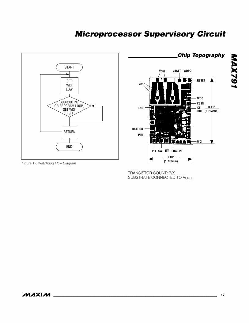
Watchdog Software ConsiderationsA way to help the watchdog timer keep a closer watchon software execution involves setting and resetting thewatchdog input at different points in the program,rather than “pulsing” the watchdog input high-low-highor low-high-low. This technique avoids a “stuck” loopwhere the watchdog timer continues to be reset withinthe loop, keeping the watchdog from timing out.
Figure 17 shows an example flow diagram where theI/O driving the watchdog input is set high at the begin-ning of the program, set low at the beginning of everysubroutine or loop, then set high again when the pro-
gram returns to the beginning. If the program should“hang” in any subroutine, the I/O is continually set lowand the watchdog timer is allowed to time out, causinga reset or interrupt to be issued.
Maximum VCC Fall TimeThe VCC fall time is limited by the propagation delay ofthe battery switchover comparator and should notexceed 0.03V/µs. A standard rule of thumb for filtercapacitance on most regulators is on the order of100µF per amp of current. When the power supply isshut off or the main battery is disconnected, the associ-ated initial VCC fall rate is just the inverse or 1A / 100µF= 0.01V/µs. The VCC fall rate decreases with time asVCC falls exponentially, which more than satisfies themaximum fall-time requirement.
Microprocessor Supervisory Circuit
16 ______________________________________________________________________________________
100
010 1000 10,000
40
20
80
60
MAX
791-
16
RESET COMPARATOR OVERDRIVE (mV)(Reset Threshold Voltage - VCC)
MAX
IMUM
TRA
NSIE
NT D
URAT
ION
(µs)
100
VCC = +5VTA = +25°C0.1µF CAPACITORFROM VOUT TO GND
Figure 16. Maximum Transient Duration Without Causing aReset Pulse vs. Reset Comparator Overdrive
MAX791
VCC
GND
PFI
R2
R1
+5V
PFO
PFO
+5V
0V
NOTE: VTRIP IS NEGATIVE
0VVTRIPV-
5 - 1.25 = 1.25 - VTRIP R1 R2
V-
Figure 15. Monitoring a Negative Voltage
MA
X7
91
Microprocessor Supervisory Circuit
______________________________________________________________________________________ 17
START
SETWDILOW
SUBROUTINEOR PROGRAM LOOP,
SET WDIHIGH
RETURN
END
Figure 17. Watchdog Flow Diagram
RESET
GND
VCC
PFO
BATT ON
VOUT VBATT
SWTPFI
0.11"(2.794mm)
0.07"(1.778mm)
WDPO
WDO
CE INCEOUT
MR LOWLINE
WDI
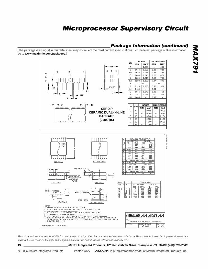
Chip Topography
TRANSISTOR COUNT: 729SUBSTRATE CONNECTED TO VOUT

MA
X7
91
Microprocessor Supervisory Circuit
18 ______________________________________________________________________________________
DIM
AA1A2A3B
B1C
D1E
E1e
eAeBL
MIN–
0.0150.1250.0550.0160.0450.0080.0050.3000.2400.1000.300
–0.115
MAX0.200
–0.1750.0800.0220.0650.0120.0800.3250.310
––
0.4000.150
MIN–
0.383.181.400.411.140.200.137.626.102.547.62
–2.92
MAX5.08
–4.452.030.561.650.302.038.267.87
––
10.163.81
INCHES MILLIMETERS
Plastic DIPPLASTIC
DUAL-IN-LINEPACKAGE(0.300 in.)
DIM
DDDDDD
MIN0.3480.7350.7450.8851.0151.14
MAX0.3900.7650.7650.9151.0451.265
MIN8.84
18.6718.9222.4825.7828.96
MAX9.9119.4319.4323.2426.5432.13
INCHES MILLIMETERSPINS
81416182024
C
A A2
E1D
E
eA
eB
A3
B1B
0° - 15°A1L
D1
e
DIM
AA1BCEeHL
MIN0.0530.0040.0140.0070.150
0.2280.016
MAX0.0690.0100.0190.0100.157
0.2440.050
MIN1.350.100.350.193.80
5.800.40
MAX1.750.250.490.254.00
6.201.27
INCHES MILLIMETERS
21-0041A
SOSMALL OUTLINE
PACKAGE(0.150 in.)
DIM
DDD
MIN0.1890.3370.386
MAX0.1970.3440.394
MIN4.808.559.80
MAX5.008.7510.00
INCHES MILLIMETERSPINS
81416
1.270.050
L
0°-8°
HE
D
e
A
A1 C
0.101mm0.004in.
B
Package Information(The package drawing(s) in this data sheet may not reflect the most current specifications. For the latest package outline information,go to www.maxim-ic.com/packages.)
MA
X7
91
Microprocessor Supervisory Circuit
C
0°-15°
AD
B1B
DIM
AB
B1CE
E1eL
L1QS
S1
MIN–
0.0140.0380.0080.2200.290
0.1250.1500.015
–0.005
MAX0.2000.0230.0650.0150.3100.320
0.200–
0.0700.098
–
MIN–
0.360.970.205.597.37
3.183.810.38
–0.13
MAX5.080.581.650.387.878.13
5.08–
1.782.49
–
2.54 0.100
Q
L
S1
e
CERDIPCERAMIC DUAL-IN-LINE
PACKAGE(0.300 in.)
S
L1
E
E1
PINS
81416182024
DIM
DDDDDD
MIN––––––
MAX0.4050.7850.8400.9601.0601.280
MIN––––––
MAX10.2919.9421.3424.3826.9232.51
INCHES MILLIMETERS
INCHES MILLIMETERS
TSS
OP
4.40
mm
.EP
S
PACKAGE OUTLINE, TSSOP 4.40mm BODY
21-0066 11
G
Package Information (continued)(The package drawing(s) in this data sheet may not reflect the most current specifications. For the latest package outline information,go to www.maxim-ic.com/packages.)
Maxim cannot assume responsibility for use of any circuitry other than circuitry entirely embodied in a Maxim product. No circuit patent licenses are
implied. Maxim reserves the right to change the circuitry and specifications without notice at any time.
19 ____________________________Maxim Integrated Products, 120 San Gabriel Drive, Sunnyvale, CA 94086 (408) 737-7600
© 2005 Maxim Integrated Products Printed USA is a registered trademark of Maxim Integrated Products, Inc.