micropilot fmr50/51/52/53/54/56/57 (sd) - … 71207371 functional safety manual micropilot...
TRANSCRIPT

SD01087F/00/EN/01.12
71207371
Functional Safety Manual
Micropilot
FMR50/51/52/53/54/56/57
Level-Radar for Liquids and Bulk Solids
with 4 to 20 mA Output Signal
Application
Operating minimum (e.g. dry run protection),
maximum (e.g. overfill protection) and range monitoring
of liquids and bulk solids of all types in systems to satisfy
particular safety systems requirements as per IEC 61508
Edition 2.0.
The measuring device fulfils the requirements
concerning
• Functional safety as per IEC 61508 Edition 2.0
• Explosion protection (depending on the version)
• Electromagnetic compatibility as per EN 61326 and
NAMUR recommendation NE 21
• Electrical safety as per IEC/EN 61010-1
Your benefits
• Used for level monitoring (MIN, MAX, range) up to
SIL 2 (single-channel architecture) or SIL 3 (multi-
channel architecture, also with homogeneous
redundancy)
– Independently assessed and certified by TÜV
Rheinland as per IEC 61508 Edition 2.0
• Permanent self-monitoring
• Continuous measurement
• Non-contact measurement is virtually independent of
product properties
• Easy commissioning
• Proof-test possible without demounting of the device
and without variation of the level
Micropilot
2 Endress+Hauser
Table of contents
SIL Declaration of Conformity . . . . . . . . . . . . . . . . . . . 3
Introduction. . . . . . . . . . . . . . . . . . . . . . . . . . . . . . . . . 4
Structure of the measuring system. . . . . . . . . . . . . . . . 4
System components . . . . . . . . . . . . . . . . . . . . . . . . . . . . . . . . . . . 4
Description of use as a protective system . . . . . . . . . . . . . . . . . . . . 5
Permitted device types . . . . . . . . . . . . . . . . . . . . . . . . . . . . . . . . . 6
Supplementary device documentation . . . . . . . . . . . . . . . . . . . . . . 7
Description of the safety requirements and
restrictions. . . . . . . . . . . . . . . . . . . . . . . . . . . . . . . . . . 8
Safety function . . . . . . . . . . . . . . . . . . . . . . . . . . . . . . . . . . . . . . . 8
Restrictions for use in safety-related applications . . . . . . . . . . . . . . 8
Functional safety parameters . . . . . . . . . . . . . . . . . . . . . . . . . . . . . 9
Behavior of device during operation and in case of error . . . . . . . 10
Installation . . . . . . . . . . . . . . . . . . . . . . . . . . . . . . . . . . . . . . . . . 11
Commissioning . . . . . . . . . . . . . . . . . . . . . . . . . . . . . . . . . . . . . 11
Operation . . . . . . . . . . . . . . . . . . . . . . . . . . . . . . . . . . . . . . . . . . 12
Maintenance . . . . . . . . . . . . . . . . . . . . . . . . . . . . . . . . . . . . . . . 18
Proof-test . . . . . . . . . . . . . . . . . . . . . . . . . . . . . . . . . . 19
Proof-test . . . . . . . . . . . . . . . . . . . . . . . . . . . . . . . . . . . . . . . . . . 19
Process for proof-testing . . . . . . . . . . . . . . . . . . . . . . . . . . . . . . . 19
Repairs. . . . . . . . . . . . . . . . . . . . . . . . . . . . . . . . . . . . 22
Repairs . . . . . . . . . . . . . . . . . . . . . . . . . . . . . . . . . . . . . . . . . . . . 22
Appendix . . . . . . . . . . . . . . . . . . . . . . . . . . . . . . . . . . 23
Notes on the redundant use of multiple sensors . . . . . . . . . . . . . 23
Commissioning or proof test protocol . . . . . . . . . . . . . . . . . . . . . 24
Certificate . . . . . . . . . . . . . . . . . . . . . . . . . . . . . . . . . 25
Micropilot
Endress+Hauser 3
SIL Declaration of Conformity
SIL-11001b
Micropilot
4 Endress+Hauser
Introduction
! Note!
General information on functional safety (SIL) is available at:
www.de.endress.com/SIL (German) or www.endress.com/SIL (English) and in Competence Brochure
CP002Z "Functional Safety in the Process Industry - Risk Reduction with Safety Instrumented Systems".
Structure of the measuring system
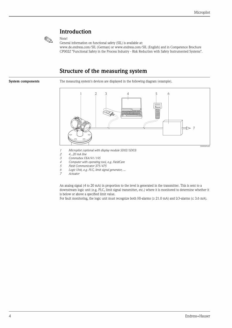
System components The measuring system's devices are displayed in the following diagram (example).
SD00326Fxx01
1 Micropilot (optional with display module SD02/SD03)
2 4...20 mA line
3 Commubox FXA191/195
4 Computer with operating tool, e.g. FieldCare
5 Field Communicator 375/475
6 Logic Unit, e.g. PLC, limit signal generator, ...
7 Actuator
An analog signal (4 to 20 mA) in proportion to the level is generated in the transmitter. This is sent to a
downstream logic unit (e.g. PLC, limit signal transmitter, etc.) where it is monitored to determine whether it
is below or above a specified limit value.
For fault monitoring, the logic unit must recognize both HI-alarms (21.0 mA) and LO-alarms ( 3.6 mA).
1 3 4 5 6
7
2

Micropilot
Endress+Hauser 5
Description of use as a
protective system
The Micropilot is a "downward-looking" measuring system that functions according to the ToF method (ToF =
Time of Flight). The distance from the reference point (process connection of the measuring device) to the
product surface is measured. High-frequency pulses are emitted by an antenna.
The pulses are reflected by the product surface, received by the electronic evaluation unit and converted into
level information. This method is also known as level radar.
Typical measuring arrangement:
FMx_03
1 Flange: reference point of measurement
2 20 mA, 100 %
3 4 mA, 0 %
The Micropilot can be used in this arrangement in safety instrumented systems for MIN safety, MAX safety
and range monitoring.
! Note!
Correct installation is a prerequisite for safe operation of the device.
1
2
3

Micropilot
6 Endress+Hauser
Permitted device types The details pertaining to functional safety in this manual relate to the device versions listed below and are valid
as of the specified software and hardware version.
Unless otherwise specified, all subsequent versions can also be used for safety instrumented systems.
A modification process according to IEC 61508 is applied for device changes.
Valid device versions for safety-related use:
Valid firmware version: as of 01.00.zz (nameplate of the device)
Valid hardware version (electronics): as of date of production 17.12.2012 (nameplate of the device)
! Note!
SIL certified devices are marked with the following symbol on the nameplate:
Feature Designation Version
010 Approval all
020 Power Supply; Output A, B*1, C*2, K
030 Display; Operation all
040 Housing all
050 Electrical Connection all
070 Antenna all
090 Seal
(only FMR51/54/57)
all
100 Process Connection all
110 Air Purge Connection
(only FMR57)
all
500 Additional Operation
Language
all
540 Application Package all
550 Calibration all
570 Service all
580 Test; Certificate
(only FMR51/52/53/54/57)
all
590 Additional Approval LA
An additional selection of any further versions is possible.
610 Accessory Mounted all
620 Accessory Enclosed all
850 Firmware Version If no version is selected here, the latest SIL-enabled SW is supplied.
Alternatively, the following SW version may be selected:
78 (01.00.zz, HART, DevRev01)
*1 For this version with current output and switch output, only the current output (terminals 1 and 2) is approved for
safety functions. The switch output can, if necessary, be wired for non-safety-oriented purposes.
*2 For this version with 2 current outputs, only the first output (terminals 1 and 2) is approved for safety functions.
The second output can, if necessary, be wired for non-safety-oriented purposes.

Micropilot
Endress+Hauser 7
Supplementary device
documentationDocumentation Contents Comment
Technical Information
TI01039F/00 (FMR50)
TI01040F/00 (FMR51/52)
TI01041F/00 (FMR53/54)
TI01042F/00 (FMR56/57)
– Technical data
– Instructions on accessories
– The documentation is supplied with
the device in pdf format on a CD.
– The documentation is also available on
the Internet.
www.endress.com.
Operating Instructions
(HART)
BA01045F/00 (FMR50)
BA01049F/00 (FMR51/52)
BA01050F/00 (FMR53/54)
BA01048F/00 (FMR56/57)
– Basic safety instructions
– Product description
– Incoming acceptance and product
identification
– Storage, Transport
– Mounting
– Electrical connection
– Operating options
– Device integration via the
HARTprotocol
– Commissioning
– Trouble shooting
– Repairs
– Maintenance
– Accessories
– Return
– Disposal
– Overview of the operating menu
– Description of device parameters
– The documentation is supplied with
the device in pdf format on a CD.
– The documentation is also available on
the Internet.
www.endress.com.
Brief Operating Instructions
(HART)
KA01099F/00 (FMR50)
KA01100F/00 (FMR51/52)
KA01101F/00 (FMR53/54)
KA01102F/00 (FMR56/57)
– Basic safety instructions
– Product description
– Incoming acceptance and product
identification
– Storage, Transport
– Mounting
– Electrical connection
– Commissioning
– The documentation is supplied with
the device in pdf format on a CD.
– The documentation is also available on
the Internet.
www.endress.com.
Description of Device Parameters
GP01014F/00
– Operating options
– Overview of the operating menu
– The "Expert" menu
– The documentation is supplied with
the device in pdf format on a CD.
– The documentation is also available on
the Internet.
www.endress.com.
Safety instructions depending
on the selected version
"Approval"
– Safety, installation and operating
instructions for devices, which are
suitable for use in potentially
explosive atmospheres or as overfill
protection (WHG, German Water
Resources Act).
Additional safety instructions
(XA, ZE) are supplied with certified device
versions.
Please refer to the nameplate for the
relevant safety instructions.
Micropilot
8 Endress+Hauser
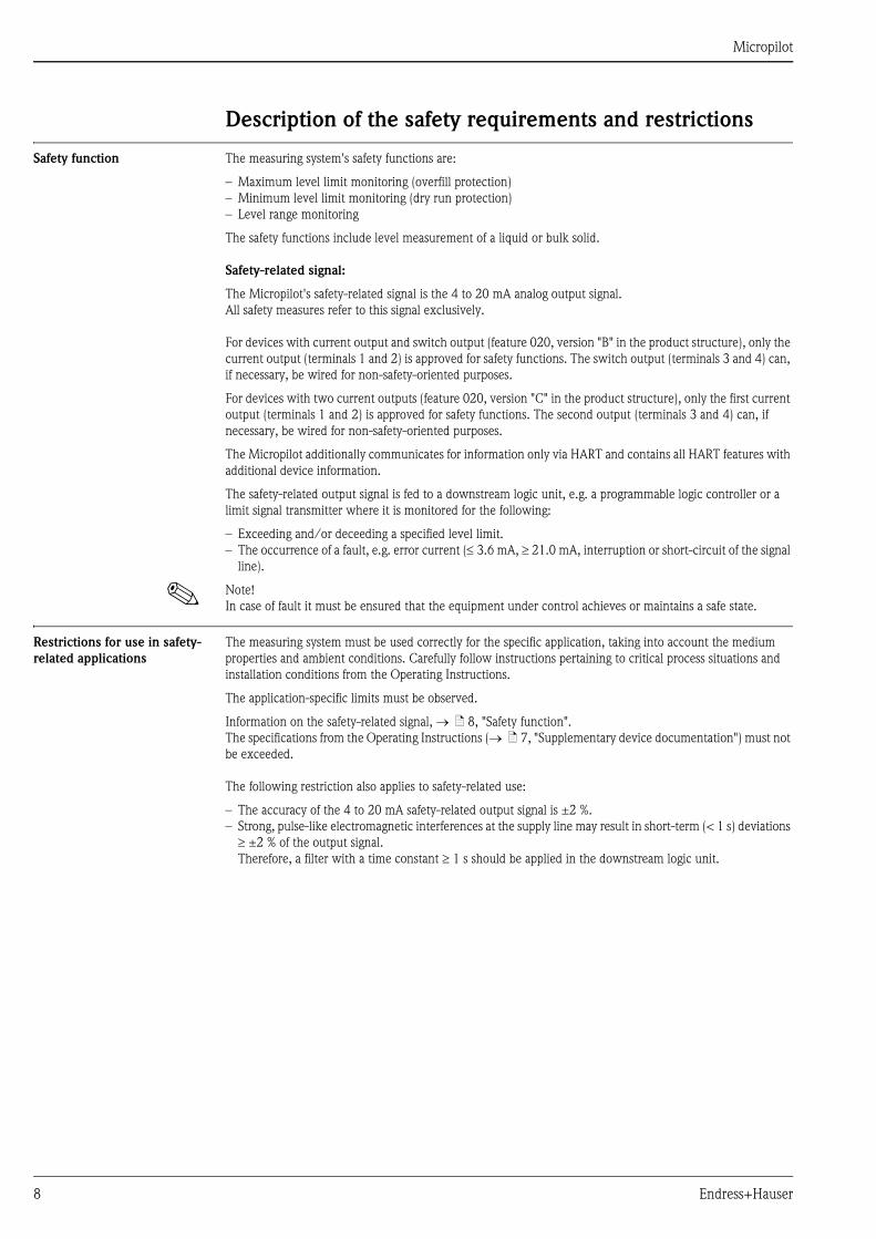
Description of the safety requirements and restrictions
Safety function The measuring system's safety functions are:
– Maximum level limit monitoring (overfill protection)
– Minimum level limit monitoring (dry run protection)
– Level range monitoring
The safety functions include level measurement of a liquid or bulk solid.
Safety-related signal:
The Micropilot's safety-related signal is the 4 to 20 mA analog output signal.
All safety measures refer to this signal exclusively.
For devices with current output and switch output (feature 020, version "B" in the product structure), only the
current output (terminals 1 and 2) is approved for safety functions. The switch output (terminals 3 and 4) can,
if necessary, be wired for non-safety-oriented purposes.
For devices with two current outputs (feature 020, version "C" in the product structure), only the first current
output (terminals 1 and 2) is approved for safety functions. The second output (terminals 3 and 4) can, if
necessary, be wired for non-safety-oriented purposes.
The Micropilot additionally communicates for information only via HART and contains all HART features with
additional device information.
The safety-related output signal is fed to a downstream logic unit, e.g. a programmable logic controller or a
limit signal transmitter where it is monitored for the following:
– Exceeding and/or deceeding a specified level limit.
– The occurrence of a fault, e.g. error current ( 3.6 mA, 21.0 mA, interruption or short-circuit of the signal
line).
! Note!
In case of fault it must be ensured that the equipment under control achieves or maintains a safe state.
Restrictions for use in safety-
related applications
The measuring system must be used correctly for the specific application, taking into account the medium
properties and ambient conditions. Carefully follow instructions pertaining to critical process situations and
installation conditions from the Operating Instructions.
The application-specific limits must be observed.
Information on the safety-related signal, ä 8, "Safety function".
The specifications from the Operating Instructions ( ä 7, "Supplementary device documentation") must not
be exceeded.
The following restriction also applies to safety-related use:
– The accuracy of the 4 to 20 mA safety-related output signal is ±2 %.
– Strong, pulse-like electromagnetic interferences at the supply line may result in short-term (< 1 s) deviations
±2 % of the output signal.
Therefore, a filter with a time constant 1 s should be applied in the downstream logic unit.

Micropilot
Endress+Hauser 9
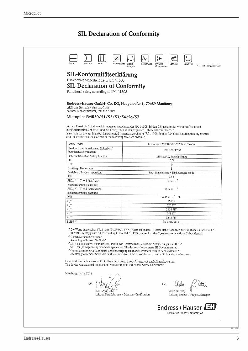
Functional safety parameters The table shows the specific functional safety parameters:
Characteristic as per IEC 61508 Value
Safety function MIN, MAX, Range
SIL SIL 2 (single-channel architecture 1oo1),
SIL 3 (multi-channel architecture, also with homogeneous
redundancy, e.g. 1oo2, 2oo3)
HFT 0
Device type B
Mode of operation Low demand mode, High demand mode
SFF 92 %
MTTR 8 h
Recommended time interval for proof-testing T1 2 years
sd 15 FIT
su 520 FIT
dd 2438 FIT
du 245 FIT
tot *1 3218 FIT
PFDavg for T1 = 1 year *2 1.09 × 10⁻³
PFDavg for T1 = 2 years *2 2.17 × 10⁻³
PFH 2.45 × 10⁻⁷ 1/h
MTBF *1 50 years
Diagnostic test interval *3 30 min
Fault reaction time *4 30 s
System reaction time *5 – In "Increased safety mode":
– for "Medium type = Liquid":
dependent on the "Tank type" parameter:
"Workbench test" (not recommended during operation): < 1 s
"Bypass/pipe": < 5 s
"Storage vessel": < 40 s
all others: < 20 s
– for "Medium type = Solid":
dependent on the parameters "Max. filling speed solid" and
"Max. draining speed solid" for filling or draining, respectively:
"No filter/test" (not recommended during operation): < 1 s
"Very fast > 8 m (26 ft)/h": < 10 s
"Fast < 8 m (26 ft)/h": < 70 s
"Medium < 4 m (13 ft)/h": < 170 s
"Standard < 2 m (6.5 ft)/h": < 340 s
"Slow < 1 m (3.3 ft)/h": < 600 s
"Very slow < 0.5 m (1.6 ft)/h": < 910 s
– In "Expert mode":
freely configurable, shortest response time:
– for level measurement: 1 s
*1 According to Siemens SN29500. This value takes into account failure types relevant to the function of the electronic
components without soft errors.
*2 Valid for ambient temperatures up to 40°C. Where the average temperature when in continuous use is in the region
of 50°C, a factor of 1.3 should be taken into account.
*3 During this time, all diagnostic functions are executed at least once.
*4 Time between error detection and error response.
*5 Step response time as per DIN EN 61298-2. For steps greater than 175 mm/6.89 in (FMR50/51/52/53/54) or
400 mm/15.7 in (FMR56/57) the step response time may exceed these values.
Micropilot
10 Endress+Hauser
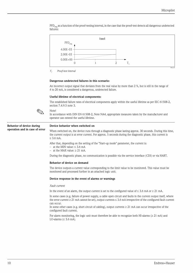
PFDavg as a function of the proof-testing interval, in the case that the proof-test detects all dangerous undetected
failures:
FMx_04
T1 Proof-test interval
Dangerous undetected failures in this scenario:
An incorrect output signal that deviates from the real value by more than 2 %, but is still in the range of
4 to 20 mA, is considered a dangerous, undetected failure.
Useful lifetime of electrical components:
The established failure rates of electrical components apply within the useful lifetime as per IEC 61508-2,
section 7.4.9.5 note 3.
! Note!
In accordance with DIN EN 61508-2, Note NA4, appropriate measures taken by the manufacturer and
operator can extend the useful lifetime.
Behavior of device during
operation and in case of error
Device behavior when switched on
When switched on, the device runs through a diagnostic phase lasting approx. 30 seconds. During this time,
the current output is at error current. For approx. 5 seconds during the diagnostic phase, this current is
3.6 mA.
After that, depending on the setting of the "Start-up mode" parameter, the current is:
– at the MIN value: 3.6 mA
– at the MAX value: 21 mA.
During the diagnostic phase, no communication is possible via the service interface (CDI) or via HART.
Behavior of device on demand
The device outputs a current value corresponding to the limit value to be monitored. This value must be
monitored and processed further in an attached logic unit.
Device response in the event of alarms or warnings
Fault current
In the event of an alarm, the output current is set to the configured value of 3.6 mA or 21 mA.
In some cases (e.g. failure of power supply, a cable open circuit and faults in the current output itself, where
the error current 21 mA cannot be set), output currents 3.6 mA irrespective of the configured fault current
can occur.
In some other cases (e.g. short circuit of cabling), output currents 21 mA can occur irrespective of the
configured fault current.
For alarm monitoring, the logic unit must therefore be able to recognize both HI-alarms (21 mA) and
LO-alarms ( 3.6 mA).
0 1 2 T1
1oo1
4.00E -03
PFDavg
2.00E -03
0.00E+00

Micropilot
Endress+Hauser 11
Alarm and warning messages
Additional information is provided by the alarm and warning messages in the form of error codes and associated
clear text messages.
The following table shows the correlation between the error code and the current output.
! Note!
When SIL locking is active on the device, additional diagnostics are activated (e.g. a comparison between the
readback-current with the nominal value). If one of these diagnostics results in an error message (e.g. F803
loop current) and the SIL locking is then deactivated, the error message remains while the error persists, even
if the diagnostics is no longer active in the unlocked state.
In this case, the device must be disconnected briefly from the power supply (e.g. by unplugging the terminals).
When the device is then restarted, a self-check is carried out, and the error message is reset where applicable.
Installation Mounting and wiring
The mounting and wiring of the device is described in the accompanying Operating Instructions ( ä 7,
"Supplementary device documentation").
Mounting orientation
The permitted mounting orientations of the device are described in the Operating Instructions.
Commissioning Commissioning of the device is described in the accompanying Operating Instructions ( ä 7,
"Supplementary device documentation").
Error code*1 Current output (message type) Note
Fxxx 21 mA or 3.6 mA xxx = three-digit number
Mxxx corresponding to measuring mode xxx = three-digit number
Cxxx corresponding to measuring mode xxx = three-digit number
Sxxx corresponding to measuring mode xxx = three-digit number
Exceptions:
Error code*1 Current output (message type) Note
M272 21 mA or 3.6 mA Main electronic failure
C484 21 mA or 3.6 mA Simulation failure mode
S942 21 mA or 3.6 mA In safety distance
*1 The error codes are listed in the Operating Instructions.

Micropilot
12 Endress+Hauser
Operation Calibration of the measuring point
Calibration of the measuring point is described in the Operating Instructions.
Check the initial factory setting of the E (zero point) and F (range) parameters in accordance with the desired
measuring range and correct if necessary.
Methods of device configuration
When using the devices in process control safety systems, the device configuration must comply with two
requirements:
1. Confirmation concept:
Proven, independent testing of safety-related parameters entered.
2. Locking concept:
Locking of the device once configuration is complete (as required by IEC 61511-1 §11.6.4 and
NE 79 §3).
To activate SIL mode, the Micropilot must run through an operating sequence, during which the device can
be operated by means of the device display or any Asset Management Tool (FieldCare, Pactware, AMS, PDM,
Field Communicator 375, …), for which integration is available.
Two methods of configuring the device are provided, which differ mainly with regard to the confirmation
concept:
1. "Increased safety mode"
While running through the commissioning sequence here, critical parameters which control functions in
the safety path are either set automatically by the device to safe values or transferred to the display/
operating tool via an alternative data format, to enable checking of the setting.
This mode can be used for standard applications.
As there are only a few safety-related parameters which can be freely configured, the risk of operating
errors is greatly reduced, and the level in the tank does not need to be changed during commissioning in
order to check the settings.
2. "Expert mode"
A larger number of safety-related parameters can be freely configured here. This means that the device
difficult applications can be adapted to. However, the settings must be checked by directly approaching
the level in the tank.
A detailed description of both modes is provided in the following sections.
! Note!
It is only in the case of SIL devices (feature 590 "Additional Approval", version "LA", "SIL declaration of
conformity") that the SIL commissioning sequence is visible on the display and in external operating tools.
For this reason, SIL locking can only be activated on these devices.

Micropilot
Endress+Hauser 13
Locking in increased safety mode
To commission the device, carry out and document the following steps in the order shown (template ä 24).
1. Reset device.
To do this, select "Diagnostics > Device reset > To factory defaults" or "Diagnostics > Device reset >
To delivery settings". This resets all parameters to defined values.
2. Carry out configuration.
The configuration procedure and the meaning of the individual parameters are described in the Operating
Instructions.
The following restrictions must be taken into account:
Description Parameter displayed
These parameters affect the safety function.
However, they may be freely configured in
accordance with the application.
In increased safety mode, it is necessary to
confirm the configured values during the
remainder of the commissioning process.
Confirmation is not required in expert mode.
Recommendation: Note configured values!
Setup > Level > Tank type *1
> Tube diameter *1, *2
> Bin type *3
> Max. filling speed *3
> Max. draining speed *3
> Empty calibration
> Full calibration
> Advanced setup > Level > Advanced process conditions
> Tank/silo height
These parameters affect the safety function
and are not freely configurable in increased
safety mode. Instead, they are automatically
set by the device at the start of the SIL/WHG
confirmation to the safety-oriented values
mentioned.
If these parameters are to be set to other
values, expert mode must be selected.
Setup > Advanced setup > Level
> Linearization
> Curr.output 1
> Display
> Level correction = 0
> Linearization type = None
> Assign current output = Level
> Damping = 0
> Backlight = Disable
Expert > Sensor > Level
> Safety sett.
> Distance offset = 0
> L max. drain speed = 0
> L max. fill speed = 0
> Level limit mode = Off
> Output mode = Level
> Jump delay echo lost = Off
> Delay time echo lost = 3 s
> Output > Curr.output 1 > Turn down = Off
> Measuring mode = Standard
> Communication > Configuration > HART address = 0

Micropilot
14 Endress+Hauser
These parameters affect the safety function
and are automatically set by the device when
configuring higher-ranking parameters
(known as application parameters).
This indirect setting is permitted in increased
safety mode. However, it is not permitted to
change the parameters directly.
If these parameters were changed directly,
only expert mode is available for selection in
the SIL/WHG confirmation.
Setup > Advanced setup > Level > Max. draining speed
> Max. filling speed
Env. curve > Envelope curve statistic
> Envelope statistics down
> Envelope statistics up
> Envelope smoothing mode
> Asymmetric envelope smoothing near down
> Asymmetric envelope smoothing near up
> Asymmetric envelope smoothing far down
> Asymmetric envelope smoothing far up
> Envelope smoothing
Expert > Sensor > Sensor prop.
> Distance
> Safety sett.
> Weighting curves
> Mapping
> First echo fact.
> Echo adjust.fine
> Tank bottom eval
> Echo tracking
> HF module mode
> Dead time
> Integration time
> Max. integration time
> Delta at integration time
> Echo lost window right
> Echo lost window left
> Draining filter
> Filling filter
> Weighting curve selection
> FAC window size
> FAC offset
> FMC window size
> FMC offset
> IEC offset
> Map offset
> Mapping window size
> First echo mode
> First echo factor
> Fine adjustment mode
> Parabolic fit window size
> Merge echo distance
> Merging echo window
> Merging ratio
> Tank bottom range
> Min. amplitude TBD
> Lower level area
> Evaluation mode
> Window size tracking
> Maximal track counter
These parameters affect the safety function
and cannot be freely configured neither in
increased safety mode nor in expert mode.
Instead they are automatically set at the start
of the SIL/WHG confirmation to the
safety-oriented values mentioned.
Setup > Advanced setup > Safety sett. > Output echo lost = Alarm
Diagnostics > Simulation > Assign measurement variable = Off
> Simulation current output 1 = Off
> Simulation device alarm = Off
> Simulation diagnostic event = 65533
Expert > Sensor > Distance > Hysteresis = 0
> Velocity filter = Off
Description Parameter displayed
Micropilot
Endress+Hauser 15
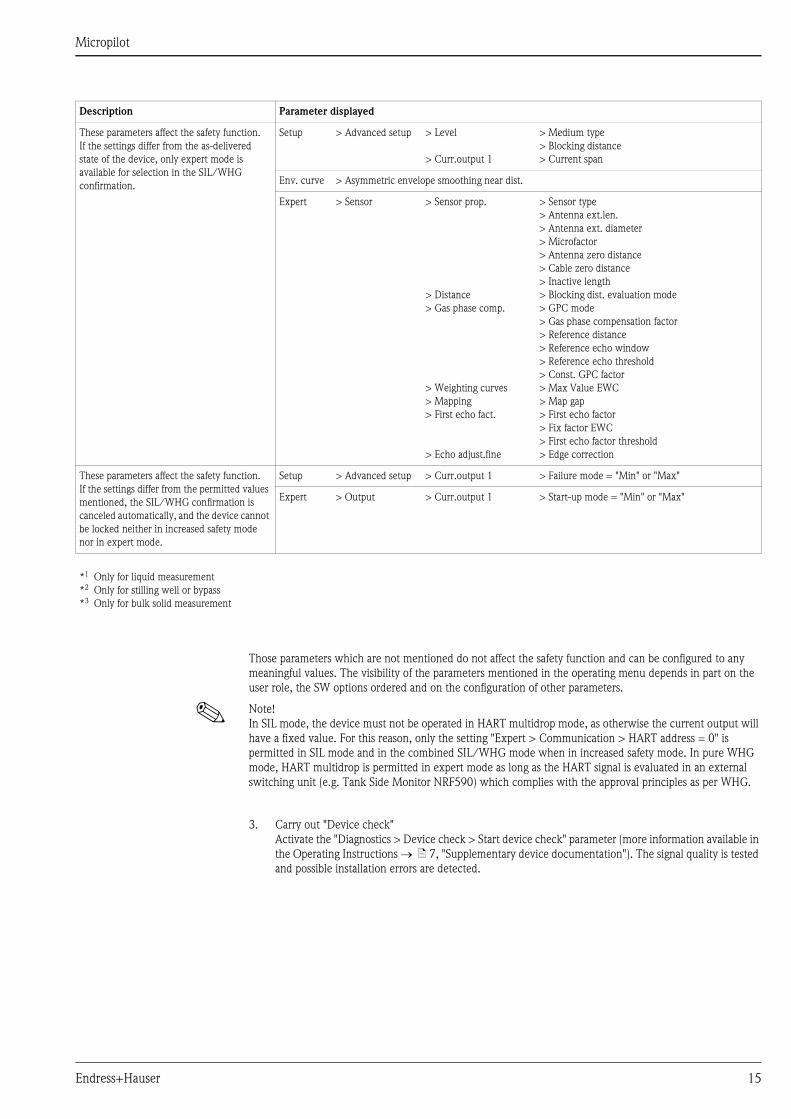
Those parameters which are not mentioned do not affect the safety function and can be configured to any
meaningful values. The visibility of the parameters mentioned in the operating menu depends in part on the
user role, the SW options ordered and on the configuration of other parameters.
! Note!
In SIL mode, the device must not be operated in HART multidrop mode, as otherwise the current output will
have a fixed value. For this reason, only the setting "Expert > Communication > HART address = 0" is
permitted in SIL mode and in the combined SIL/WHG mode when in increased safety mode. In pure WHG
mode, HART multidrop is permitted in expert mode as long as the HART signal is evaluated in an external
switching unit (e.g. Tank Side Monitor NRF590) which complies with the approval principles as per WHG.
3. Carry out "Device check"
Activate the "Diagnostics > Device check > Start device check" parameter (more information available in
the Operating Instructions ä 7, "Supplementary device documentation"). The signal quality is tested
and possible installation errors are detected.
These parameters affect the safety function.
If the settings differ from the as-delivered
state of the device, only expert mode is
available for selection in the SIL/WHG
confirmation.
Setup > Advanced setup > Level
> Curr.output 1
> Medium type
> Blocking distance
> Current span
Env. curve > Asymmetric envelope smoothing near dist.
Expert > Sensor > Sensor prop.
> Distance
> Gas phase comp.
> Weighting curves
> Mapping
> First echo fact.
> Echo adjust.fine
> Sensor type
> Antenna ext.len.
> Antenna ext. diameter
> Microfactor
> Antenna zero distance
> Cable zero distance
> Inactive length
> Blocking dist. evaluation mode
> GPC mode
> Gas phase compensation factor
> Reference distance
> Reference echo window
> Reference echo threshold
> Const. GPC factor
> Max Value EWC
> Map gap
> First echo factor
> Fix factor EWC
> First echo factor threshold
> Edge correction
These parameters affect the safety function.
If the settings differ from the permitted values
mentioned, the SIL/WHG confirmation is
canceled automatically, and the device cannot
be locked neither in increased safety mode
nor in expert mode.
Setup > Advanced setup > Curr.output 1 > Failure mode = "Min" or "Max"
Expert > Output > Curr.output 1 > Start-up mode = "Min" or "Max"
*1 Only for liquid measurement
*2 Only for stilling well or bypass
*3 Only for bulk solid measurement
Description Parameter displayed

Micropilot
16 Endress+Hauser
4. Start SIL/WHG confirmation sequence.
To do so, enter the appropriate locking code in the "Setup > Advanced setup > SIL/WHG confirmation
> Set write prot." parameter:
– WHG: 7450
– SIL: 7452
– SIL and WHG: 7454
! Note!
In this way, forbidden parameter changes (e.g. via external operating tools if the confirmation sequence
is performed at the device display) are prevented already during the SIL/WHG confirmation sequence.
5. For "Commissioning" select the "Increased safety mode" entry from the list.
The device checks the parameter settings in accordance with the table ( ä 13) and carries out a forced
switching of parameters if necessary. Once testing is complete, "SIL/WHG preparation: Finished" is
displayed, and the commissioning sequence can continue.
! Note!
If configuration was not performed in accordance with the specifications in point 2, only "Expert mode"
can be selected at this point.
6. Simulate distance values via the "Value sim. dist." parameter, and verify that the response of the current
output is correct. For MIN monitoring and MAX monitoring, in each case simulate a distance directly
above and below the switch point. For range monitoring, 5 distance values should be simulated which
cover the entire measuring range.
" Caution!
During distance simulation, the loop current does not correspond to the measured value. It must be
ensured that there is no risk of danger arising from this.
7. Confirm that the distance simulation is correct. To do so, select the "Yes" value for the "Sim. correct"
parameter.
8. Compare the character string which is now output ("0123456789+-,.") with the reference string printed
here, and confirm if the output is correct.
9. The parameters previously configured and which require confirmation are transferred via an independent
data format to the display/operating tool.
Check the parameters one after the other and confirm if correct.
10. Enter locking code again under "Set write prot.":
– WHG: 7450
– SIL: 7452
– SIL and WHG: 7454
The "End of sequence" message indicates that the device was successfully locked.
11. Optional, hardware locking may also be activated (via the DIP switch marked "WP" on main electronics).

Micropilot
Endress+Hauser 17
Locking in expert mode
To commission the device, carry out and document the following steps in the order shown (template ä 24).
1. Reset device.
To do this, select "Diagnostics > Device reset > To factory defaults" or "Diagnostics > Device reset > To
delivery settings". This resets all parameters to defined values.
2. Carry out configuration.
The configuration procedure and the meaning of the individual parameters are described in the Operating
Instructions.
The basic conditions under point 2 in "Increased safety mode" must be taken into account.
3. Carry out "Device check".
Activate the "Diagnostics > Device check > Start device check" parameter (more information available in
the Operating Instructions ä 7, "Supplementary device documentation"). The signal quality is tested
here and possible installation errors are detected.
4. Start SIL/WHG confirmation sequence.
To do so, enter the appropriate locking code in the "Setup > Advanced setup > SIL/WHG confirmation
> Set write prot." parameter:
– WHG: 7450
– SIL: 7452
– SIL and WHG: 7454
5. For "Commissioning" select the "Expert mode" entry from the list.
The device checks the parameter settings in accordance with the table ( ä 13) and forces the
switching of parameters if necessary. Once testing is complete, "SIL/WHG preparation: Finished" is
displayed, and the commissioning sequence can continue.
6. Carry out function test.
For MIN monitoring and MAX monitoring, in each case approach a level directly above and below the
switch point. For range monitoring, 5 distance values should be approached which cover the entire
measuring range.
7. Confirm that the function test has been successful. To do so, select the "Yes" entry for "Conf. funct. test".
8. Enter locking code again under "Set write prot.":
– WHG: 7450
– SIL: 7452
– SIL and WHG: 7454
The "End of sequence" message indicates that the device was successfully locked.
9. Optional, hardware locking may also be activated (via the dip switch marked "WP" on main electronics).
Micropilot
18 Endress+Hauser
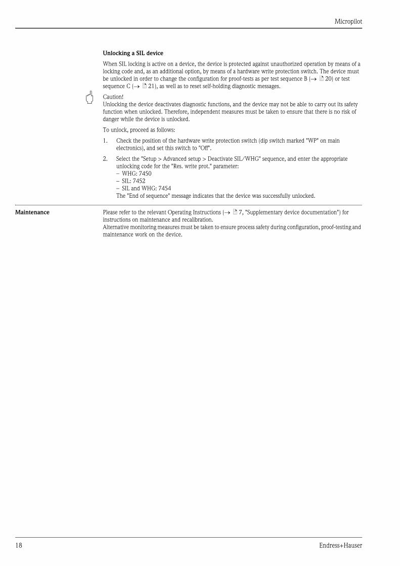
Unlocking a SIL device
When SIL locking is active on a device, the device is protected against unauthorized operation by means of a
locking code and, as an additional option, by means of a hardware write protection switch. The device must
be unlocked in order to change the configuration for proof-tests as per test sequence B ( ä 20) or test
sequence C ( ä 21), as well as to reset self-holding diagnostic messages.
" Caution!
Unlocking the device deactivates diagnostic functions, and the device may not be able to carry out its safety
function when unlocked. Therefore, independent measures must be taken to ensure that there is no risk of
danger while the device is unlocked.
To unlock, proceed as follows:
1. Check the position of the hardware write protection switch (dip switch marked "WP" on main
electronics), and set this switch to "Off".
2. Select the "Setup > Advanced setup > Deactivate SIL/WHG" sequence, and enter the appropriate
unlocking code for the "Res. write prot." parameter:
– WHG: 7450
– SIL: 7452
– SIL and WHG: 7454
The "End of sequence" message indicates that the device was successfully unlocked.
Maintenance Please refer to the relevant Operating Instructions ( ä 7, "Supplementary device documentation") for
instructions on maintenance and recalibration.
Alternative monitoring measures must be taken to ensure process safety during configuration, proof-testing and
maintenance work on the device.

Micropilot
Endress+Hauser 19
Proof-test
Proof-test Check the operativeness and safety of safety functions at appropriate intervals!
The operator must determine the time intervals.
You can refer to the diagram "Proof-test interval", ä 10, for this purpose.
! Note!
In a single-channel architecture, the PFDavg value to be used depends on the diagnostic rate of coverage for the
proof-test (PTC = Proof Test Coverage) and the intended lifetime (LT = Lifetime), as specified in the following
formula:
For the proof-tests described as follows, the respective proof test coverages are specified, which may be used
for calculation.
Proof-testing of the device can be performed as follows:
– Approaching the level in the original tank ( test sequence A).
– Removing of the device and measurement of the surface of a medium with comparable properties
( test sequence B).
– Device self-test and level simulation ( test sequence C).
No change of level in the tank is necessary for this sequence.
You must also check that all cover seals and cable entries are sealing correctly.
" Caution!
During the proof-test, alternative monitoring measures must be taken to ensure process safety.
! Note!
If one of the test criteria from the following test sequences is not fulfilled, the device may no longer be used as
part of a safety instrumented system.
The purpose of proof-testing is to detect random device failures (du). The impact of systematic faults on the
safety function is not covered by this test and must be assessed separately.
Systematic faults can be caused, for example, by process material properties, operating conditions, build-up or
corrosion.
Process for proof-testing Test sequence A
Preparation
1. Connect suitable measuring device (recommended accuracy better ±0.1 mA) to the current output.
2. Determine the safety setting (level limit or range monitoring).
Procedure for level limit monitoring
1. Approach a level directly below (MAX monitoring) or directly above (MIN monitoring) the level limit to
be monitored.
2. Read the output current, record it and assess for accuracy.
3. Approach a level directly above (MAX monitoring) or directly below (MIN monitoring) the level limit to
be monitored.
4. Read the output current, record it and assess for accuracy.
5. The test is deemed successful if the current in step 2 does not result in activation of the safety function
but the current in step 4 does.
Procedure for range monitoring
1. Approach five levels within the range to be monitored.
2. Read the output current at each level value, record it and assess for accuracy.
3. The test is deemed successful if the current values in step 2 are within the required level of accuracy.
• • • •• • •PFD = T +PTC MTTR + (1 – PTC) LT� � �avg DU 1 DD DU1 12 2

Micropilot
20 Endress+Hauser
! Note!
The proof-test is deemed to have failed if the expected current value deviates for a specific level by > ±2 %.
For troubleshooting, Operating Instructions ( ä 7, "Supplementary device documentation").
98 % of dangerous, undetected failures are detected using this test (Proof test coverage, PTC = 0.98).
Test sequence B
Preparation
1. Prepare a test tank with test medium (dielectric constant comparable to that of the medium to be
measured). The tank may be open or closed.
For installation instructions, Operating Instructions ( ä 7, "Supplementary device
documentation").
2. Deactivate SIL mode. To do so, enter the appropriate unlocking code in the "Setup > Advanced setup >
Deactivate SIL/WHG" operating menu:
– WHG: 7450
– SIL: 7452
– SIL and WHG: 7454
3. Remove the device and mount it in the closed or above the open test tank, respectively.
4. Connect suitable measuring device (recommended accuracy better than ±0.1 mA) to the current output.
5. Perform interference echo mapping if the shape and size of the test tank is different.
6. Determine the safety setting (level limit or range monitoring).
Procedure for level limit monitoring
Test sequence A
Procedure for range monitoring
Test sequence A.
! Note!
The proof-test is deemed to have failed if the expected current value deviates for a specific level by > ±2 %.
For troubleshooting, Operating Instructions ( ä 7, "Supplementary device documentation").
98 % of dangerous, undetected failures are detected using this test (Proof test coverage, PTC = 0.98).
" Caution!
After re-installation in the original tank, SIL mode must be reactivated, ä 12.
If an interference echo mapping was performed in the test tank, it is necessary following installation in the
original tank to carry out another interference echo mapping that is valid for that tank.
Micropilot
Endress+Hauser 21
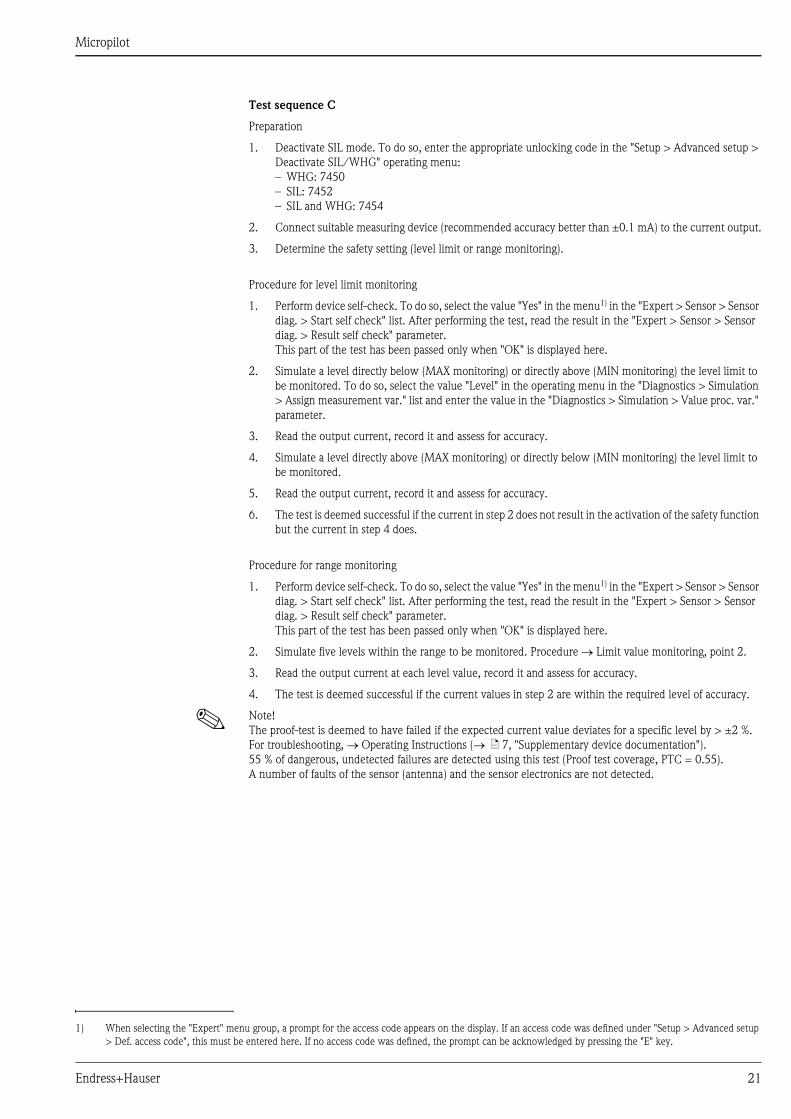
Test sequence C
Preparation
1. Deactivate SIL mode. To do so, enter the appropriate unlocking code in the "Setup > Advanced setup >
Deactivate SIL/WHG" operating menu:
– WHG: 7450
– SIL: 7452
– SIL and WHG: 7454
2. Connect suitable measuring device (recommended accuracy better than ±0.1 mA) to the current output.
3. Determine the safety setting (level limit or range monitoring).
Procedure for level limit monitoring
1. Perform device self-check. To do so, select the value "Yes" in the menu1) in the "Expert > Sensor > Sensor
diag. > Start self check" list. After performing the test, read the result in the "Expert > Sensor > Sensor
diag. > Result self check" parameter.
This part of the test has been passed only when "OK" is displayed here.
2. Simulate a level directly below (MAX monitoring) or directly above (MIN monitoring) the level limit to
be monitored. To do so, select the value "Level" in the operating menu in the "Diagnostics > Simulation
> Assign measurement var." list and enter the value in the "Diagnostics > Simulation > Value proc. var."
parameter.
3. Read the output current, record it and assess for accuracy.
4. Simulate a level directly above (MAX monitoring) or directly below (MIN monitoring) the level limit to
be monitored.
5. Read the output current, record it and assess for accuracy.
6. The test is deemed successful if the current in step 2 does not result in the activation of the safety function
but the current in step 4 does.
Procedure for range monitoring
1. Perform device self-check. To do so, select the value "Yes" in the menu1) in the "Expert > Sensor > Sensor
diag. > Start self check" list. After performing the test, read the result in the "Expert > Sensor > Sensor
diag. > Result self check" parameter.
This part of the test has been passed only when "OK" is displayed here.
2. Simulate five levels within the range to be monitored. Procedure Limit value monitoring, point 2.
3. Read the output current at each level value, record it and assess for accuracy.
4. The test is deemed successful if the current values in step 2 are within the required level of accuracy.
! Note!
The proof-test is deemed to have failed if the expected current value deviates for a specific level by > ±2 %.
For troubleshooting, Operating Instructions ( ä 7, "Supplementary device documentation").
55 % of dangerous, undetected failures are detected using this test (Proof test coverage, PTC = 0.55).
A number of faults of the sensor (antenna) and the sensor electronics are not detected.
1) When selecting the "Expert" menu group, a prompt for the access code appears on the display. If an access code was defined under "Setup > Advanced setup
> Def. access code", this must be entered here. If no access code was defined, the prompt can be acknowledged by pressing the "E" key.

Micropilot
22 Endress+Hauser
Repairs
Repairs Repairs on the devices must always be carried out by Endress+Hauser.
Safety functions cannot be guaranteed if repairs are carried out by anybody else.
Exceptions:
The customer may replace the following components on condition that original replacement parts are used, the
member of staff responsible has previously been trained by Endress+Hauser to carry out this task and the
relevant repair instructions are observed:
– Display
– Antennas
– Overvoltage protection
– Main electronics
– I/O modules
– Terminals for I/O modules
– Housing covers
– Seal kits for housing covers
– Housing filters (vent plugs)
– Safety clamps, housing
The replaced components must be sent to Endress+Hauser for the purpose of fault analysis.
Once the components have been replaced, a proof-test must be carried out as per test sequence A ( ä 19)
or test sequence B ( ä 20).
In the event of failure of a SIL-labeled Endress+Hauser device, which has been operated in a protection
function, the "Declaration of Contamination and Cleaning" with the corresponding note "Used as SIL device in
protection system" must be enclosed when the defective device is returned.
Please refer to the Section "Return" in the Operating Instructions ( ä 7, "Supplementary device
documentation").

Micropilot
Endress+Hauser 23
Appendix
Notes on the redundant use of
multiple sensors
This section provides additional information regarding the use of homogeneously redundant sensors e.g. 1oo2
or 2oo3 architectures.
The common cause factors ß and ßD indicated in the table below are minimum values for the Micropilot.
These must be used when designing the sensor subsystem.
The device meets the requirements for SIL 3 in homogeneously redundant applications.
The following must be taken into account in proof-testing:
– If an error is detected in one of the redundantly operated devices, the other devices must be checked to see
if there is the same error.
Minimum value ß with homogeneous redundant use 2 %
Minimum value ßD with homogeneous redundant use 1 %

Micropilot
24 Endress+Hauser
Commissioning or proof test
protocol
Protokoll_01-EN
*1 Only for liquid measurement
*2 Only for stilling well or bypass
*3 Only for bulk solid measurement
System-specific data
Device-specific commissioning parameters ( )only in “Increased safety mode”
Company
Measuring point / TAG no.
System / Plant
Device type / Order
Serial number of device
Name
Date
Signature
code
Access code (if individual to each device)
Locking code used WHG:SIL:SIL and WHG:
Tank type *
Tube diameter * , *
Bin type *
Max. filling speed *
Max. draining speed *
Empty calibration
Full calibration
Advanced process conditions
Tank/silo height
1
1 2
3
3
3
Test step
Proof-test protocol
1. Current value 1
2. Current value 2
3. Current value 3 (if necessary)
4. Current value 4 (if necessary)
5. Current value 5 (if necessary)
Set point Actual value
745074527454

Micropilot
Endress+Hauser 25
Certificate

Micropilot
26 Endress+Hauser

Micropilot
Endress+Hauser 27

Micropilot
www.endress.com/worldwide
SD01087F/00/EN/01.12
71207371
FM+SGML 9.0 71207371