microphone test system - nti audio nti audio microphone test system is a powerful solution ... which...
TRANSCRIPT
www.nti-audio.com Mar 18, Page 1 / 6
Microphone Test System
Product data
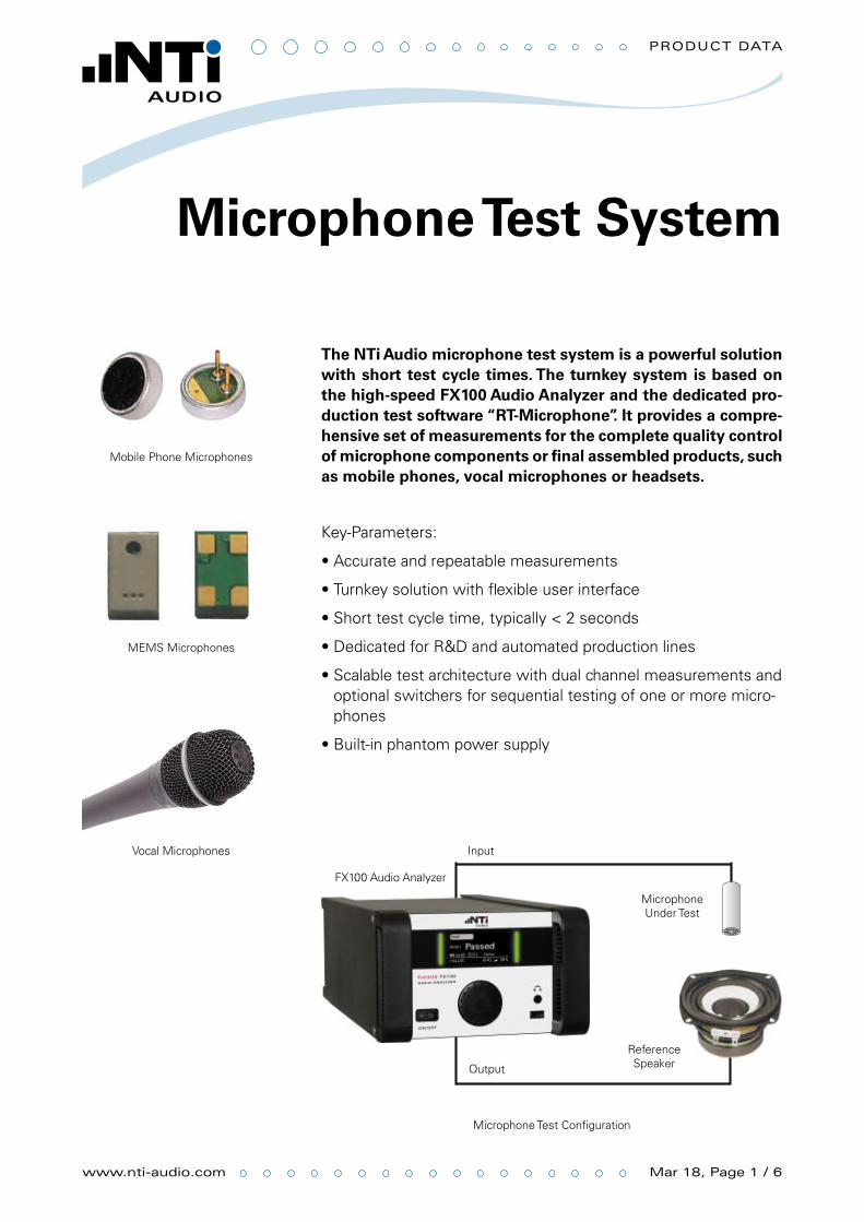
The NTi Audio microphone test system is a powerful solution with short test cycle times. The turnkey system is based on the high-speed FX100 Audio Analyzer and the dedicated pro-duction test software “RT-Microphone”. It provides a compre-hensive set of measurements for the complete quality control of microphone components or final assembled products, such as mobile phones, vocal microphones or headsets.
Key-Parameters:
Accurate and repeatable measurements •
Turnkey solution with flexible user interface •
Short test cycle time, typically < 2 seconds•
Dedicated for R&D and automated production lines•
Scalable test architecture with dual channel measurements and •optional switchers for sequential testing of one or more micro-phones
Built-in phantom power supply •
Mobile Phone Microphones
MEMS Microphones
Vocal Microphones
Microphone Test Configuration
FX100 Audio Analyzer
Microphone Under Test
Reference Speaker
Input
Output
www.nti-audio.com Page 2 / 6
Product data
Flexible Parameter and Tolerance Setting
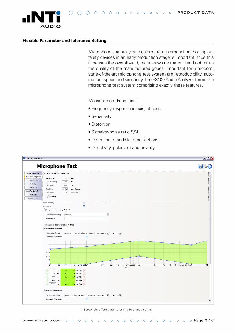
Microphones naturally bear an error rate in production. Sorting out faulty devices in an early production stage is important, thus this increases the overall yield, reduces waste material and optimizes the quality of the manufactured goods. Important for a modern, state-of-the-art microphone test system are reproducibility, auto-mation, speed and simplicity. The FX100 Audio Analyzer forms the microphone test system comprising exactly these features.
Measurement Functions:
Frequency response in-axis, off-axis•
Sensitivity•
Distortion•
Signal-to-noise ratio S/N•
Detection of audible imperfections•
Directivity, polar plot and polarity•
Screenshot: Test parameter and tolerance setting

www.nti-audio.com Page 3 / 6
Product data
Polar plot measured of cardiod microphone
High-Resolution Polar Plot Measurement
The polar plot analysis with the NTi Audio precision turntable com-plements the microphone measurement system to an all-in-one solution. The polar diagram displays the directional characteristic related to the measurement frequency of the microphone. For de-tailed analysis, the measurement angles might be set in arbitrary resolution down to less than 1°.
The high-speed FX100 Audio Analyzer generates a series of fast sweep signals, covering the complete audio band from 20 Hz – 20 kHz, and turns the microphone to the configured angles be-tween the sweeps. The measurement time halves by choosing the 180° mode, which mirrors the polar image. The polar plot graphics can be adjusted after the completed measurement, thus the microphone test system offers full flexibility for post process-ing.
www.nti-audio.com Page 4 / 6
Product data
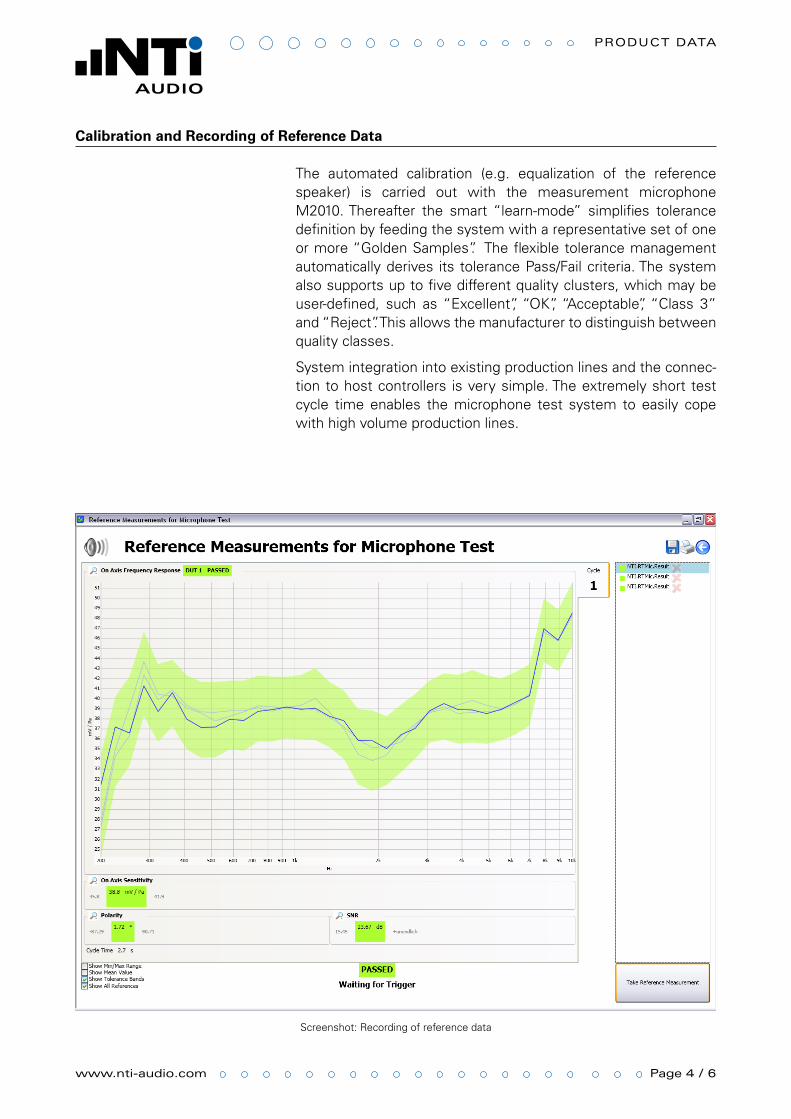
Screenshot: Recording of reference data
Calibration and Recording of Reference Data
The automated calibration (e.g. equalization of the reference speaker) is carried out with the measurement microphone M2010. Thereafter the smart “learn-mode” simplifies tolerance definition by feeding the system with a representative set of one or more “Golden Samples”. The flexible tolerance management automatically derives its tolerance Pass/Fail criteria. The system also supports up to five different quality clusters, which may be user-defined, such as “Excellent”, “OK”, “Acceptable”, “Class 3” and “Reject”. This allows the manufacturer to distinguish between quality classes.
System integration into existing production lines and the connec-tion to host controllers is very simple. The extremely short test cycle time enables the microphone test system to easily cope with high volume production lines.
www.nti-audio.com Page 5 / 6
Product data
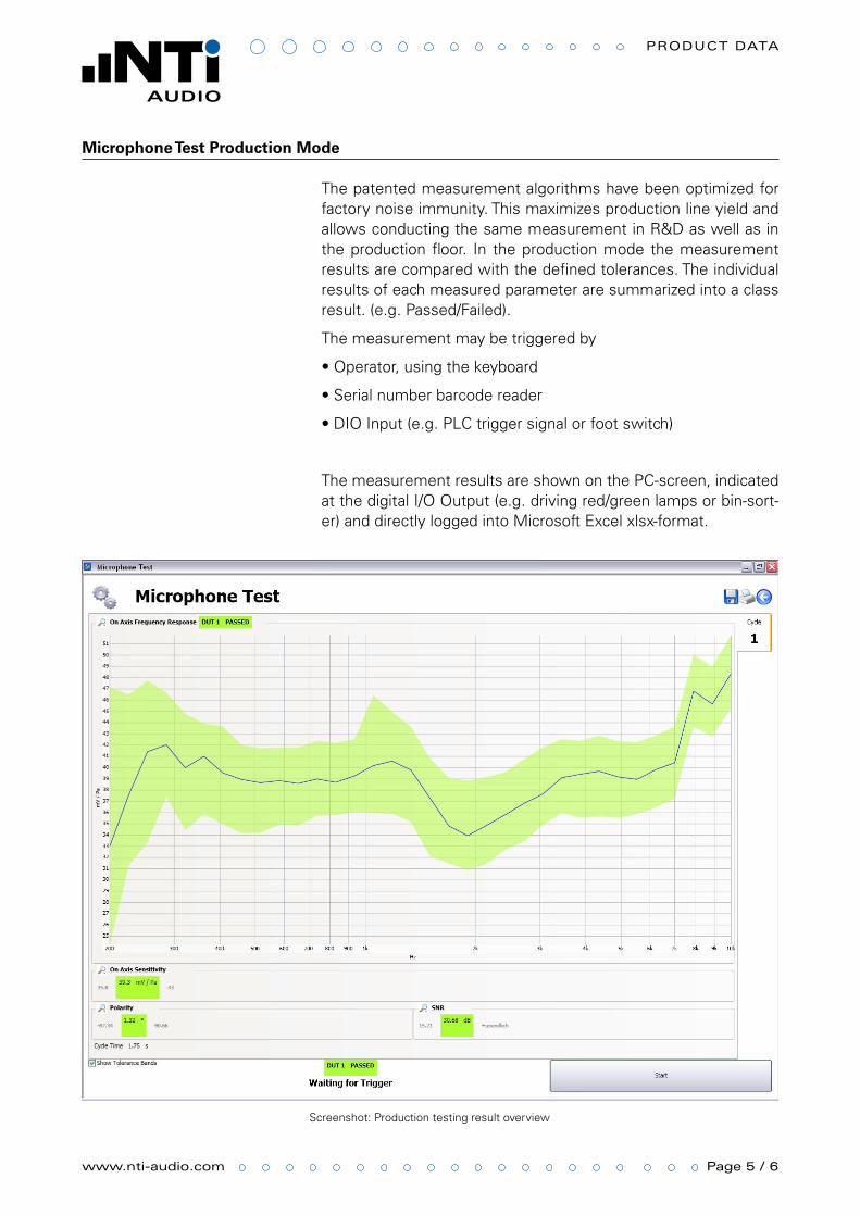
Screenshot: Production testing result overview
Microphone Test Production Mode
The patented measurement algorithms have been optimized for factory noise immunity. This maximizes production line yield and allows conducting the same measurement in R&D as well as in the production floor. In the production mode the measurement results are compared with the defined tolerances. The individual results of each measured parameter are summarized into a class result. (e.g. Passed/Failed).
The measurement may be triggered by
Operator, using the keyboard•
Serial number barcode reader•
DIO Input (e.g. PLC trigger signal or foot switch)•
The measurement results are shown on the PC-screen, indicated at the digital I/O Output (e.g. driving red/green lamps or bin-sort-er) and directly logged into Microsoft Excel xlsx-format.
www.nti-audio.com Page 6 / 6
Product data
All information subject to change without notice. FX100, RT-Microphone and M2010 are trademarks of NTi Audio AG.
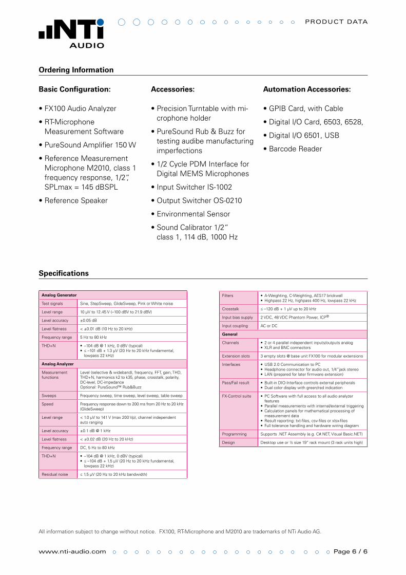
Ordering Information
Basic Configuration:
FX100 Audio Analyzer •
RT-Microphone •Measurement Software
PureSound Amplifier 150 W •
Reference Measurement •Microphone M2010, class 1 frequency response, 1/2“, SPLmax = 145 dBSPL
Reference Speaker•
Accessories:
Precision Turntable with mi-•crophone holder
PureSound Rub & Buzz for •testing audibe manufacturing imperfections
1/2 Cycle PDM Interface for •Digital MEMS Microphones
Input Switcher IS-1002•
Output Switcher OS-0210•
Environmental Sensor•
Sound Calibrator 1/2“ •class 1, 114 dB, 1000 Hz
Automation Accessories:
GPIB Card, with Cable•
Digital I/O Card, 6503, 6528, •
Digital I/O 6501, USB•
Barcode Reader•
Analog Generator
Test signals Sine, StepSweep, GlideSweep, Pink or White noise
Level range 10 μV to 12.45 V (–100 dBV to 21.9 dBV)
Level accuracy ±0.05 dB
Level flatness < ±0.01 dB (10 Hz to 20 kHz)
Frequency range 5 Hz to 80 kHz
THD+N –104 dB @ 1 kHz, 0 dBV (typical)•≤ –101 dB + 1.3 μV (20 Hz to 20 kHz fundamental, •lowpass 22 kHz)
Analog Analyzer
Measurement functions
Level (selective & wideband), frequency, FFT, gain, THD, THD+N, harmonics k2 to k35, phase, crosstalk, polarity, DC-level, DC-impedance Optional: PureSound™ Rub&Buzz
Sweeps Frequency sweep, time sweep, level sweep, table sweep
Speed Frequency response down to 200 ms from 20 Hz to 20 kHz (GlideSweep)
Level range < 1.0 μV to 141 V (max 200 Vp), channel independent auto ranging
Level accuracy ±0.1 dB @ 1 kHz
Level flatness < ±0.02 dB (20 Hz to 20 kHz)
Frequency range DC, 5 Hz to 80 kHz
THD+N –104 dB @ 1 kHz, 0 dBV (typical)•≤ –104 dB + 1.5 μV (20 Hz to 20 kHz fundamental, •lowpass 22 kHz)
Residual noise ≤ 1.5 μV (20 Hz to 20 kHz bandwidth)
Filters A-Weighting, C-Weighting, AES17 brickwall•Highpass 22 Hz, highpass 400 Hz, lowpass 22 kHz•
Crosstalk ≤ –120 dB + 1 μV up to 20 kHz
Input bias supply 2 VDC, 48 VDC Phantom Power, ICP®
Input coupling AC or DC
General
Channels 2 or 4 parallel independent inputs/outputs analog•XLR and BNC connectors•
Extension slots 3 empty slots @ base unit FX100 for modular extensions
Interfaces USB 2.0 Communication to PC•Headphone connector for audio out, 1/4”jack stereo•LAN (prepared for later firmware extension)•
Pass/Fail result Built-in DIO-Interface controls external peripherals•Dual color display with green/red indication•
FX-Control suite PC Software with full access to all audio analyzer •featuresParallel measurements with internal/external triggering•Calculation panels for mathematical processing of •measurement dataResult reporting: txt-files, csv-files or xlsx-files•Full tolerance handling and hardware wiring diagram•
Programming Supports .NET Assembly (e.g. C#.NET, Visual Basic.NET)
Design Desktop use or ½ size 19’’ rack mount (3 rack units high)
Specifications