microlupi operating manual...
TRANSCRIPT

MicroLUPI� Operating Manual
OMP-0448
Zygo Corporation Laurel Brook Road P.O. Box 448 Middlefield, Connecticut 06455-0448 Telephone: (860) 347-8506 Fax: (860) 346-4188 E-mail: [email protected] Website: www.zygo.com

Customer Information
© Copyright 2000 by Zygo Corporation; All Rights Reserved. • Product or company names mentioned in thismanual are trademarks or registered trademarks of their respective companies, and are hereby acknowledged.
i
ZYGO CUSTOMER SUPPORTFor help within North America, please use the contacts listed below. For help in othercountries, please contact your local Zygo representative. Be sure to supply theinstrument model and serial number, and the software version.
PHONE Monday - Friday, 8 a.m. - 5 p.m. (Eastern Standard Time)(800) ZYGO NOW (800) 994-6669or (860) 704-5191
FAX (860) 346-4188
INTERNET [email protected]
WRITE Zygo CorporationLaurel Brook RoadP.O. Box 448Middlefield, CT 06455-0448Attn: Customer Support
MANUAL REVISION INFORMATIONThe document (OMP) number and the applicable revision letter for this manual appear onthe title page. The publication date appears below.
Revision Publication Date Revision Publication Date1st Release August 2001
MANUAL NOTATIONS
Warning! Denotes a hazard that could cause injury to personnel, and can alsocause damage to the equipment.
Note: Provides helpful information.
NOTICE: The descriptions, drawings, and specifications contained herein are subject tochange. Zygo is not responsible for errors or omissions herein or for incidental damagesin connection with the furnishing or use of this information. This document shall not bereproduced, photocopied, or duplicated, in whole or in part, without prior writtenapproval of Zygo Corp.
Customer Information
ii
ZYGO STATEMENT OF WARRANTY AND PRODUCT SUPPORTZygo Corporation provides this warranty to protect its customers from defects in product workmanshipor product materials. This warranty covers all products manufactured by Zygo Corporation. Zygowarrants that the equipment purchased will be free from any defects in material and/or workmanshipunder normal operating conditions for a period of one year from the date of shipment.In addition, being committed to providing our customers with superior service, Zygo will support allstandard products for a period of five years after the sale of the last newly-manufactured unit. Beyondthis five-year period, we will continue to support these products on a "best-effort" basis.WARRANTY SERVICEZygo's responsibility under this warranty shall be limited to the repair or replacement (at Zygo's option)of defective equipment at no cost to the buyer, except for transportation, cleaning, and recalibrationcharges.Zygo will perform warranty service by: (1) sending replacement parts with appropriate installationinstructions to the buyer, the buyer returning his defective part to Zygo or; (2) repairing the product at aZygo repair facility after it has been returned freight prepaid, or; (3) at the buyer's request, dispatching aservice representative to the buyer's facility. The buyer shall pay Zygo's travel and living expenses aswell as travel time.Defective products or parts will be repaired or replaced with new or like-new parts. These replacementparts will be warranted for a period of 90 days after they are shipped, or for the remainder of the originalwarranty period, whichever is longer. Warranty service will be performed only if the buyer notifiesZygo within 14 days of discovering any defects. Equipment or parts that are to be returned to Zygo mustbe issued a Return Authorization number. This number can be obtained by contacting the Zygo ServiceDepartment. Should Zygo's subsequent inspection reveal that the parts were not defective, all expensesincurred by Zygo shall be charged back to the buyer. Defective equipment that is replaced shall becomethe property of Zygo.Warranty period begins when the product is shipped from Zygo. Replacement parts, serviceworkmanship, used equipment, and refurbished equipment are warranted for a period of 90 days.RETURNSUnused and undamaged products, in their original shipping containers, may be returned for credit within30 days of receipt. All such products will be subject to a restocking fee equal to 20 percent of thepurchase price. Custom products are not returnable.EXCLUSIONSThe above warranty and product support statement applies only to equipment that is an integral part of aZygo manufactured product. It does not apply to peripheral equipment manufactured by others, such as:computers, printers, vibration isolation tables, etc. In such cases, the warranty and the support that theoriginal manufacturer supplies will apply.In addition, warranty service does not include or apply to any product or part which, in Zygo's judgment:a. Has been repaired by others, improperly installed, altered, modified, or damaged in any way.b. Malfunctions because the customer has failed to perform maintenance, calibration checks or good
operating procedures.c. Is expendable or consumable (such as panel lights, fuses, batteries, windows, and filters) if such
items were operable at the time of initial use.d. Requires replacement because of decomposition due to chemical action.e. Fails because of poor facility, operating conditions, or utilities.Other than expressly described above, Zygo makes no express or implied warranties, including anyregarding merchantability or fitness for a particular purpose relating to the use or performance of theequipment. Zygo will not be liable for personal injury or property damage (unless caused solely by itsown negligence), loss of profit or other incidental or consequential damages arising out of the use orinability to use the equipment. Nor does this warranty apply to any equipment, which has been subjectto misuse, neglect or accident; or repaired or altered by other than service representatives qualified byZygo.
01/96

Customer Information
iii
CE Notice
Marking by the CE symbol indicates compliance of this Zygo Corp. instrument to EMC(electromagnetic compatibility) Directive and the Low Voltage Directive of the EuropeanUnion. Such marking indicates that this system meets the following technical standards:
EN 55011 – “Limits and methods of measurements or radio disturbancecharacteristics of ISM (Industrial Scientific & Medical) radio frequency equipment.”Class A, for use in typical commercial environments.
EN 55022 – “Limits and methods of measurements of radio disturbancecharacteristics of ITE (Information Technology Equipment).” Class A, for use intypical commercial environments.
EN 50082-1 1992 – “Electromagnetic compatibility generic immunity standard for theresidential, commercial, and light industrial environments.”
EN 61010-1 1993/A2: 1995 – “Safety requirements for electrical equipment formeasurement, control and laboratory use – Part 1:General requirements.”
EN 60825-1:1994/IEC825-1 :1993 – “Safety of laser products—Part 1. Equipmentclassification, requirements and user’s guide. Part 2. Safety of optical fibrecommunication systems.”
A Declaration of Conformity in accordance with the preceding directives and standardshas been made and is on file at Zygo Corporation, Middlefield, Connecticut, USA.

Customer Information
iv

Contents
v
CHAPTER 1 – OVERVIEW AND SAFETYThe MicroLUPI System............................................................................................. 1-1
Options........................................................................................................... 1-1How the MicroLUPI Works .......................................................................... 1-3
MicroLUPI Components............................................................................................ 1-4Specifications................................................................................................. 1-5Motor Driver Assembly................................................................................. 1-6Motion Controller .......................................................................................... 1-6
Computer Components .............................................................................................. 1-7Laser Safety ............................................................................................................... 1-8
Laser Safety Standards .................................................................................. 1-8Product Use Warning..................................................................................... 1-8Output Beam Data ......................................................................................... 1-8Laser Emission Control Devices ................................................................... 1-9Laser Safety Labels........................................................................................ 1-9
Safety Labels ............................................................................................................. 1-11Setting Objective Crash Protection................................................................ 1-12
CHAPTER 2 – INSTALLATIONNote Regarding Installation....................................................................................... 2-1Preinstallation Considerations ................................................................................... 2-1
Operating Environment ................................................................................. 2-2Required Utilities........................................................................................... 2-2
Installation Checklist ................................................................................................. 2-3Positioning Components – Space Requirements ....................................................... 2-4Cable Connections ..................................................................................................... 2-5Installing and Removing an Objective ...................................................................... 2-7Setting the Objective’s Working Distance ................................................................ 2-7Leveling the Head to the X/Y Stage .......................................................................... 2-8
CHAPTER 3 – MAKING MEASUREMENTSNote on MetroPro Documentation............................................................................. 3-1A Note About Operation............................................................................................ 3-2Start Up...................................................................................................................... 3-2Location of Controls .................................................................................................. 3-3Motion Controller Controls ....................................................................................... 3-3
Using the Motion Controller.......................................................................... 3-4Light Level Controls.................................................................................................. 3-5
The Light Level Window............................................................................... 3-5Making and Using System Error Files....................................................................... 3-6Measurement Overview............................................................................................. 3-8
Contents
vi
CHAPTER 3 – CONTINUEDThe MicroLUPI Application...................................................................................... 3-9
MicroLUPI Controls Window ....................................................................... 3-10Radius Measurement Parameters................................................................... 3-11Auto Calibrate Parameters ............................................................................. 3-11Measuring the Radius Calibration Standard .................................................. 3-12
Using the Pattern Editor............................................................................................. 3-13Sample Steps for Creating a Pattern .............................................................. 3-13Pattern Controls Window .............................................................................. 3-14
Frequently Used MicroLUPI Software Operations ................................................... 3-15Shutdown ................................................................................................................... 3-16
CHAPTER 4 – MEASUREMENT TYPESChoosing the Right Objective.................................................................................... 4-1Surface Reflection Measurement............................................................................... 4-3Radius of Curvature Measurement ............................................................................ 4-3
CHAPTER 5 – MAINTENANCEGeneral Care .............................................................................................................. 5-1Maintenance and Care for Computer Components.................................................... 5-1Maintenance and Care for the MicroLUPI ................................................................ 5-2
Cleaning of External Surfaces ....................................................................... 5-2Cleaning Optics ............................................................................................. 5-2Recommended Optical Cleaning Procedures ................................................ 5-3
Servicing the MicroLUPI .......................................................................................... 5-4Returning Equipment to Zygo Corporation............................................................... 5-4
(1) US patents pending.
1-1
Overview and Safety Chapter
1In This Chapter
• The MicroLUPI System- Options- How the MicroLUPI Works
• MicroLUPI Components- Specifications
• Computer Components• Laser Safety• General Safety
– Setting Objective Crash Protection
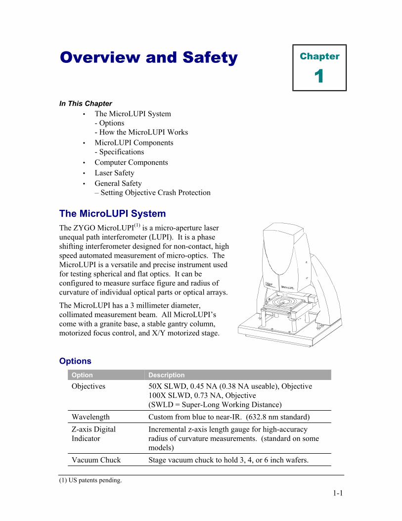
The MicroLUPI SystemThe ZYGO MicroLUPI(1) is a micro-aperture laserunequal path interferometer (LUPI). It is a phaseshifting interferometer designed for non-contact, highspeed automated measurement of micro-optics. TheMicroLUPI is a versatile and precise instrument usedfor testing spherical and flat optics. It can beconfigured to measure surface figure and radius ofcurvature of individual optical parts or optical arrays.
The MicroLUPI has a 3 millimeter diameter,collimated measurement beam. All MicroLUPI’scome with a granite base, a stable gantry column,motorized focus control, and X/Y motorized stage.
OptionsOption DescriptionObjectives 50X SLWD, 0.45 NA (0.38 NA useable), Objective
100X SLWD, 0.73 NA, Objective(SWLD = Super-Long Working Distance)
Wavelength Custom from blue to near-IR. (632.8 nm standard)Z-axis DigitalIndicator
Incremental z-axis length gauge for high-accuracyradius of curvature measurements. (standard on somemodels)
Vacuum Chuck Stage vacuum chuck to hold 3, 4, or 6 inch wafers.
MicroLUPI
1-2
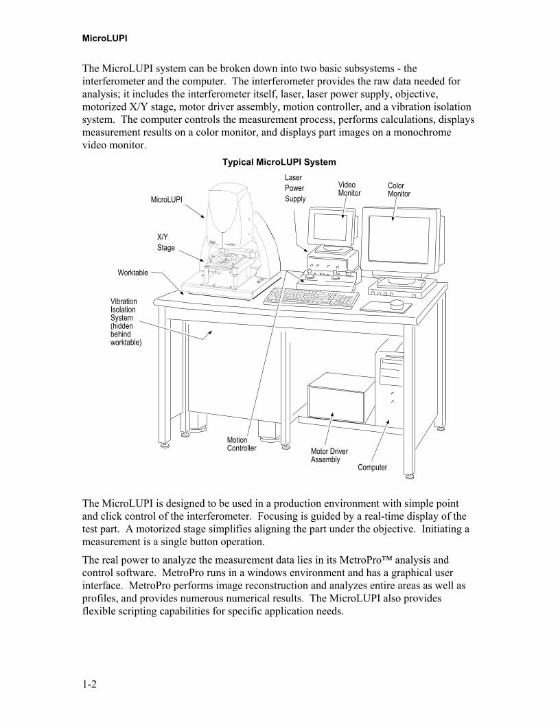
The MicroLUPI system can be broken down into two basic subsystems - theinterferometer and the computer. The interferometer provides the raw data needed foranalysis; it includes the interferometer itself, laser, laser power supply, objective,motorized X/Y stage, motor driver assembly, motion controller, and a vibration isolationsystem. The computer controls the measurement process, performs calculations, displaysmeasurement results on a color monitor, and displays part images on a monochromevideo monitor.
Typical MicroLUPI System
Motor DriverAssembly
Computer
ColorMonitor
MotionController
VibrationIsolationSystem(hiddenbehindworktable)
Worktable
X/YStage
VideoMonitor
LaserPowerSupplyMicroLUPI
The MicroLUPI is designed to be used in a production environment with simple pointand click control of the interferometer. Focusing is guided by a real-time display of thetest part. A motorized stage simplifies aligning the part under the objective. Initiating ameasurement is a single button operation.
The real power to analyze the measurement data lies in its MetroPro™ analysis andcontrol software. MetroPro runs in a windows environment and has a graphical userinterface. MetroPro performs image reconstruction and analyzes entire areas as well asprofiles, and provides numerous numerical results. The MicroLUPI also providesflexible scripting capabilities for specific application needs.

Overview and Safety
1-3
How the MicroLUPI WorksThe MicroLUPI is a Twyman-Green, unequal-path interferometer.Light from the laser is ported to theMicroLUPI head through a fiberoptic cable. The laser beam is splitinto two beams by an internalbeamsplitter. One portion exits theinterferometer through the objectiveand reflects from the test surfaceback into the interferometer. Theother portion reflects from aninternal, high quality phase-shiftingreference mirror assembly. Bothportions are then recombined anddirected onto a solid-state camera.
Helium-neon LaserCamera
Fold Mirrors
Beamsplitter
Phase-ShiftingMirror Assembly
Objective
Attenuator
Due to surface irregularities, the test or measurement wavefront travels differentdistances. When the reference and measurement wavefronts are recombined, the wavesare out of phase and form an interference pattern. This interference pattern between thetwo light wavefronts results in an image of light and dark bands, called fringes, thatindicate the surface quality of the part being tested. Beam differences indicate surfacetopography and the variation from an “ideal” surface of the part being measured.
The phase-shifting reference mirror assembly uses a piezoelectric transducer (or PZT) tomove the reference element forward and backward, causing constant phase variationsbetween the reference wavefront and the measurement wavefront. The motion of thereference element is precisely controlled and is synchronized with the frame rate of thesolid-state video camera. During a data acquisition sequence, the computer takes several“snapshots” of the interference pattern, each at a point when the interfering wavefrontshave undergone a 90-degree phase shift in relation to one another.
These snapshots are processed in MetroPro by the computer to determine the phase of thewavefront at each point when the interfering wavefronts have undergone a 90-degreephase shift in relation to one another. The result is a very accurate map of the wavefrontand therefore, the quality of the component being tested.
Measurements are three-dimensional. Vertical measurements, normal to the surface, areperformed interferometrically. Lateral measurements, in the plane of the surface, areperformed by calculating the pixel size from the field of view of the objective in use.Results are displayed on a color display as solid images, plots, and numericrepresentations of the surface or wavefront.

MicroLUPI
1-4
MicroLUPI ComponentsActual equipment may vary; see specification page for more detail. Items not to scale.
Motion Controller
VideoMonitor
Motor DriverAssembly
Worktable
VibrationIsolation System
LaserPower Supply
MicroLUPI
MotorizedX/Y Stage
MicroLUPIThe MicroLUPI is a phase-shiftinginterferometer. It provides non-contactmeasurement and analysis of highlycurved, nominally spherical surfaces,radius of curvature, and transmittedwavefront measurements of micro-optics.The MicroLUPI objective forms aconverging spherical wavefront fortesting spherical parts.
X/Y Motorized StageHolds the part under test and provides forpositioning under the objective.
Video MonitorDisplays a monochrome live image of thepart under test.
Laser Power SupplyProvides power for the laser. Foradditional information, refer to themanual provided by Melles Griot.
Motion Controllerand Motor Driver AssemblyDrives the stages. Moves the X/Y stagefor part positioning and the MicroLUPIZ-Axis for part focusing.
Vibration Isolation SystemIsolates the interferometer fromenvironmental vibrations that degrademeasurements.
WorktableNests against the vibration isolationsystem and holds the various systemcomponents.

Overview and Safety
1-5
MicroLUPIGeneral:Dimensions: see Chapter 2, “PositioningComponents”Weight: 170 lb (77 kg)Measurement Technique: Phase-shifting interferometry
Laser:Type: frequency stabilized Helium-Neon laser with fiber optic outputWavelength: 632.8 nanometersMaximum Output Power: <1 milliwattOutput Power at Instrument Aperture: ≤1 milliwattTest Beam Diameter: 3 mmCoherence Length: ≥10 meters
Objectives:Mounting: DovetailType: Infinity Corrected SLWDMag. N.A. Working Dist.50X 0.45(1) 13.80 mm100X 0.73 4.70 mm(1) 0.38 NA useable
Z-Drive (Focus) Stage:Motor: DC brushless, microstepperDrive: leadscrewRange: 6 in. (152 mm)Resolution: 4 µin. (0.1 µm)
X/Y Stage:Motor: DC brushless, microstepperDrive: leadscrewRange: 6 in. (152 mm)Resolution: 4 µin. (0.1 µm)Maximum Velocity: 0.50 in/sec (12.7 mm/sec)
Sample Viewing:Camera Size: 640 x 480 pixels maximumViewing: 9 in. monochrome video monitor and MetroPro on-screen displayFocus: manual or automatic
Test Part Characteristics:Type: nominally spherical surfaces (usingobjective) and flat surfaces (without objective)Radius of Curvature: from 100 µm to 3 mmReflectivity: 4 to 100 %
Utility Requirements:Electrical: 90 – 250 VAC, 50/60 Hz
(for laser power supply, motor driver assembly,video monitor, and computer) The MicroLUPIreceives +12 VDC from Zygo Controller Boardinstalled in the computer
Compressed Air (for Vibration Isolation Table): 60 psi minimum, with 1/4 in. input
Operating Environment:Temperature: 15° to 30°C (59° to 86° F)Rate of Temperature Change: <1.0°C/15 min.Humidity: 5 to 95% relative, noncondensingVibration: Frequency Isolation 1Hz < freq < 120Hz
Compliance:DHHS Laser Safety Classification: Class II laser product conforming to NCDRH regulations.

MicroLUPI
1-6
Motor Driver AssemblyPhysical Characteristics:
Dimensions as shown.Weight: 16.3 lb. (7.4 kg)
Electrical:Incoming Power:100/240 VAC, 50/60 HzPower Dissipation: 200 watts max.Fuse Rating (supply module): 2A 250V
13.3( 337 )
11.0( 279)
7.6( 194)
Do not blockfan vent
Dimensions shown in inches and (millimeters).
Motion Controller
Physical Characteristics:Dimensions as shown.Weight: 6.0 lb (2.7 kg)
Electrical:Incoming power and signal from Motor Driver Assembly
FocusJoystick
StageJoystick
EmergencyStop
7.3(184)
5.5(140)
11.5(292)
Dimensions shown in inches and (millimeters).
Overview and Safety
1-7
Computer Components
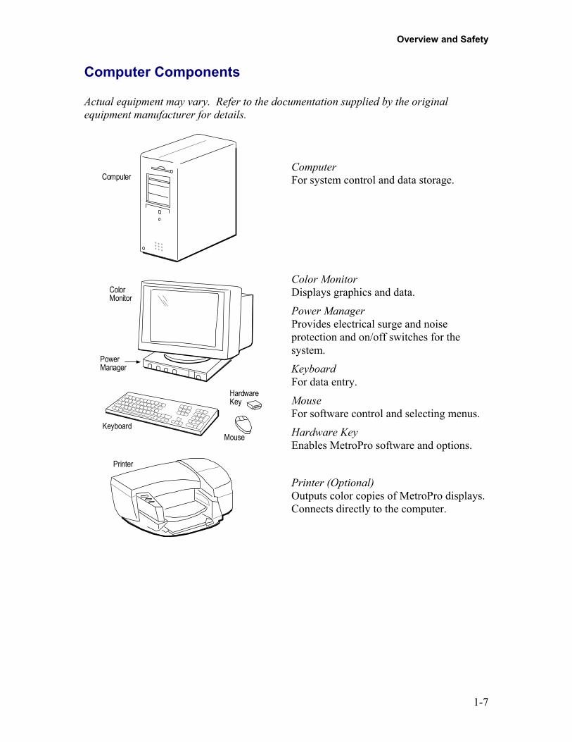
Actual equipment may vary. Refer to the documentation supplied by the originalequipment manufacturer for details.
Computer
ColorMonitor
PowerManager
Keyboard
HardwareKey
Mouse
Printer
ComputerFor system control and data storage.
Color MonitorDisplays graphics and data.
Power ManagerProvides electrical surge and noiseprotection and on/off switches for thesystem.
KeyboardFor data entry.
MouseFor software control and selecting menus.
Hardware KeyEnables MetroPro software and options.
Printer (Optional)Outputs color copies of MetroPro displays.Connects directly to the computer.
MicroLUPI
1-8
Laser SafetyThe MicroLUPI emits visible red light only; no invisible radiation is emitted. Theradiation emitted cannot burn or drill holes, even if a lens is used to focus the light.However, the laser light emitted by the MicroLUPI should be treated with caution andcommon sense. It will not damage skin, but to protect your eyes, do not look directly intothe laser beam or stare at its bright reflections.
Laser Safety StandardsThe American National Standard for the Safe Use of Lasers (ANSI Z136.1-1986) classifiesthis laser product as low power-Class II (per Table A1), and provides reasonable andadequate guidelines for its safe use. The user and personnel responsible for the safe use ofthe MicroLUPI in the user’s organization should consult the ANSI standard. It is availablefrom:
The American National Standards Institute1430 BroadwayNew York, New York 10018
The MicroLUPI conforms to the National Center for Devices and Radiological Health(NCDRH) of the Food and Drug Administration and to international laser safetyregulations.
To encourage proper laser safety and to abide by the above laser safety regulations, Zygosupplies the information listed on the next page. Refer to the following tables and figure tolocate the controls and the labels listed.
Product Use WarningWarningUse of controls or adjustments or performance of procedures otherthan those specified herein may result in hazardous radiationexposure.
WarningFor complete laser safety information refer to the Melles Griotmanual included with the system. To stop laser emission, turn offthe keyed power switch on the laser power supply.
Overview and Safety
1-9
Output Beam DataLaser Medium: Frequency stabilized Helium-Neon with fiber
optic output
Radiant Power: <1 milliwatt
Output Power atInstrument Aperture: ≤1 milliwatt
Wavelength: 632.8 nanometers
Laser Emission Control Devices
Device Function
Emission Indicator (on laser power supply) When lit, indicates that power is beingsupplied to the laser, and that Class II laserradiation may be emitted from theinstrument’s aperture.
Power Switch (Keyed power switch onlaser power supply)
In the off position, the laser is notenergized and laser radiation is not emittedfrom the instrument.
Laser Safety Labels
Label Purpose
Class II Laser Warning Federal Requirement for Class II lasers.
Aperture Labels the instrument’s aperture throughwhich laser radiation is emitted.
Noninterlocked Protective Housing Reminds you that when the covers areremoved, and the system is turned on,Class II laser radiation is being emitted.
Certification Shows that Zygo Corp. has conformed tothe DHHS standard.
Identification Provides information about the instrument,including serial number, manufacture date,model number, etc.
MicroLUPI
1-10
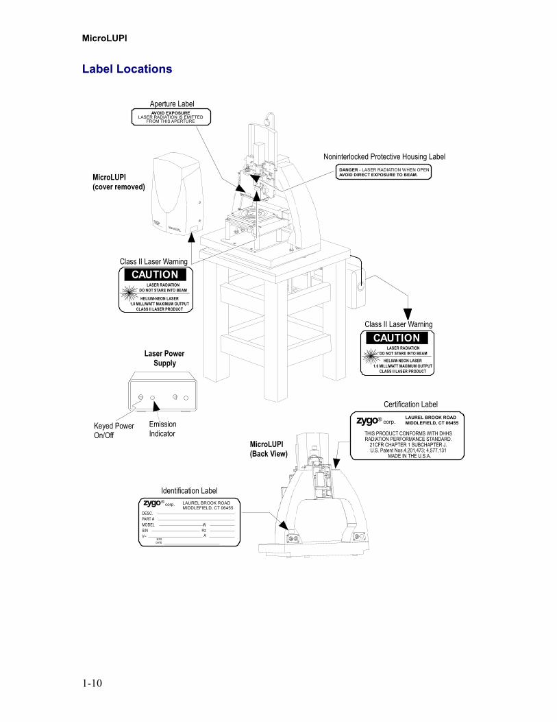
Label Locations
MicroLUPI(cover removed)
AVOID EXPOSURELASER RADIATION IS EMITTED
FROM THIS APERTURE
Aperture Label
DANGER - LASER RADIATION WHEN OPENAVOID DIRECT EXPOSURE TO BEAM.
Noninterlocked Protective Housing Label
DESC.PART #MODELS/NV~
WHz
A
LAUREL BROOK ROADMIDDLEFIELD, CT 06455
MFGDATE
corp.zygo®
Identification Label
CAUTIONLASER RADIATION
DO NOT STARE INTO BEAM
HELIUM-NEON LASER1.0 MILLIWATT MAXIMUM OUTPUT
CLASS II LASER PRODUCT
Class II Laser Warning
Laser PowerSupply
Keyed PowerOn/Off
EmissionIndicator
MicroLUPI(Back View)
Certification Label
THIS PRODUCT CONFORMS WITH DHHSRADIATION PERFORMANCE STANDARD.
21CFR CHAPTER 1 SUBCHAPTER J.U.S. Patent Nos.4,201,473; 4,577,131
MADE IN THE U.S.A.
LAUREL BROOK ROADMIDDLEFIELD, CT 06455corp.zygo®
LASER RADIATIONDO NOT STARE INTO BEAM
HELIUM-NEON LASER1.0 MILLIWATT MAXIMUM OUTPUT
CLASS II LASER PRODUCT
CAUTIONClass II Laser Warning

Overview and Safety
1-11
Safety LabelsThe following table describes the general meaning of safety labels found on theinstrument. Specific warnings are covered in the applicable section within this manual.Failure to follow the safety labels and the recommendations in this manual could result indamage to personnel and the instrument, and may void the warranty.
Label Meaning
General hazard. Proceed with caution.Refer to the manual for instructions.
Electrical shock hazard. Proceed withcaution, there is a risk of electrical shock.
Hot surface; possibility of burns. Keephands and objects away.
Objective crash warning. Do not drive theobjective into the part or stage.
Disconnect power.
Refer to the manual for instructions.
Earth ground.
Protective conductor terminal.
MicroLUPI
1-12
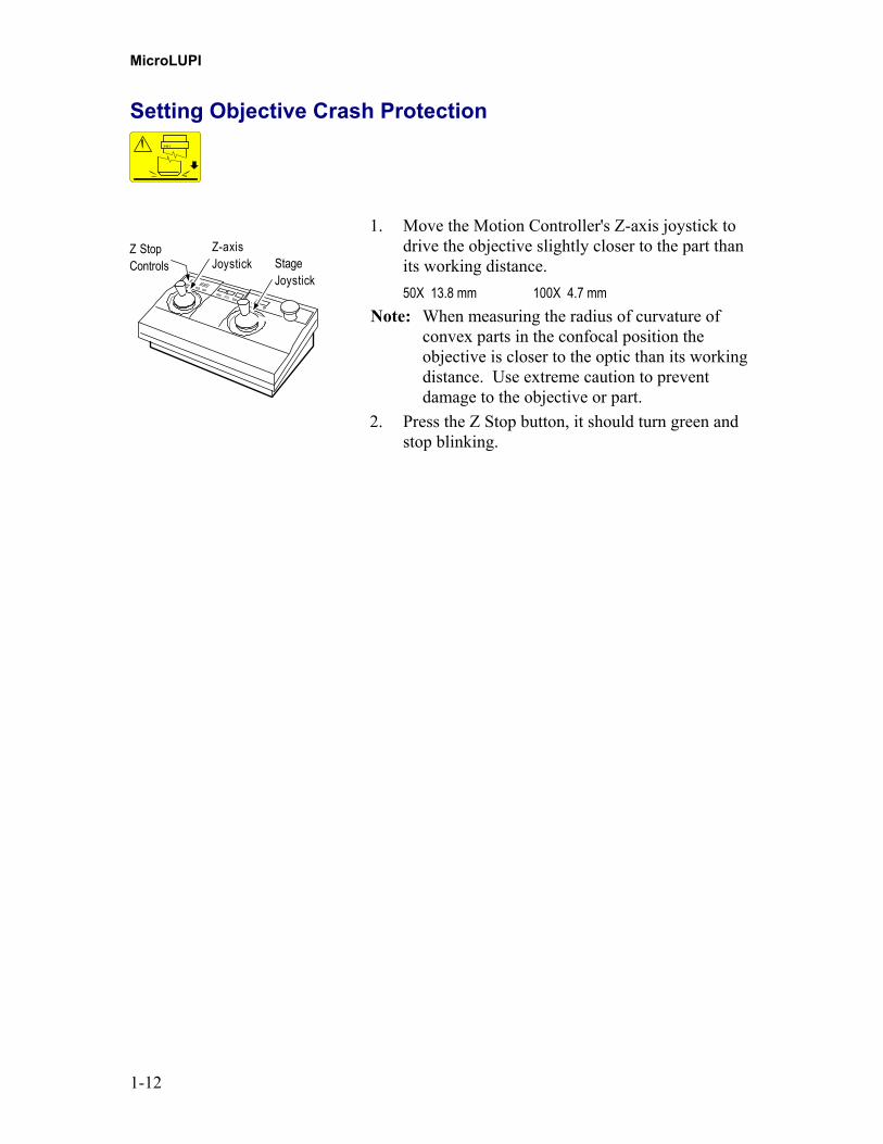
Setting Objective Crash Protection
Z StopControls
Z-axisJoystick Stage
Joystick
1. Move the Motion Controller's Z-axis joystick todrive the objective slightly closer to the part thanits working distance.50X 13.8 mm 100X 4.7 mm
Note: When measuring the radius of curvature ofconvex parts in the confocal position theobjective is closer to the optic than its workingdistance. Use extreme caution to preventdamage to the objective or part.
2. Press the Z Stop button, it should turn green andstop blinking.
2-1
Installation Chapter
2In This Chapter
• Note Regarding Installation• Preinstallation Considerations
- Operating Environment– Required Utilities
• Installation Checklist• Positioning Components – Space Requirements• Cable Connections• Installing and Removing an Objective Assembly• Leveling the Head to the X/Y Stage
Note Regarding InstallationThis equipment is intended for Category 2 Installation per EN 61010-1, Clause 5.4.1, ofthe Low Voltage Directive of the European Union.
This chapter describes the appropriate operating environment, which should beconsidered before the system is set up. It also provides installation instructions.
Installation instructions for the computer are covered separately in documentationprovided by the original manufacturers.
WarningInstallation must be performed by Zygo Corporation trainedpersonnel.
Preinstallation ConsiderationsBecause your instrument is capable of measuring to the sub-Angstrom level, theenvironment in which it is installed is significant and will have an effect on its overallperformance. Before installing your instrument, you should carefully consider theoperating location to ensure that the system can be easily installed and operate asdesigned.

MicroLUPI
2-2
Operating EnvironmentVibration Isolation - Vibration is the most significant environmental concern for thesystem, and the most difficult to control. Vibration can be introduced by any of severalsources: floors with insufficient support or rigidity, acoustic noise, other equipment (fans,etc.), human activity, and so on. The vibration isolation table included with theMicroLUPI should minimize vibration effects.Ideally, the floor of the installation site should be a poured concrete slab at ground level.This greatly reduces large-amplitude vibrations. Small amplitude vibrations transmittedthrough the ground, such as those caused by human activity, can be eliminated by using avibration isolation system.Acoustic vibration (sound) of sufficient amplitude can cause vibration of the instrument,items under test, and even of the vibration isolation table. This is especially true of low-frequency vibrations, which may not be audible even at relatively high amplitude.Uninsulated walls made are prone to retransmitting acoustic vibration from adjoiningareas and suspended ceilings can couple roof mounted air conditioning noise.Vibration can also be transmitted to the instrument through connecting cables. Be carefulnot to run cables where they would be touching sources of vibration or are likely to bejarred or kicked. Don’t place the keyboard, mouse, or anything that has moving parts, onthe vibration isolation table.Temperature Change- Rapid temperature changes degrade system performance becausedifferent materials absorb and release heat at different rates, resulting in unevenexpansion and contraction of the instrument and components under test. Temperaturedifferences can be caused by air conditioning, heating devices, or vents. Wide concurrenttemperature differences in the operating environment also degrade performance becausethey create air turbulence.Air Turbulence - Air turbulence, or the movement of air, causes uneven air densitywithin small areas, which can refract parts of the measurement beam and alter themeasurement. Fans or blowers may help to even out temperature differences in theoperating area, but they can introduce air turbulence if positioned improperly.Airborne Impurities - Smoke, dust, and oil impurities can accumulate on opticalcomponents; degrading system performance and even ruining optical coatings.
Required UtilitiesElectrical - Supply voltage must be 100/240 V at 50/60 Hz. The system should beconnected to an isolated circuit with an earth ground.
WarningThe power manager plug is used as the disconnecting device.Ensure that the outlet is accessible.
Air Supply - The Vibration Isolation Table requires a compressed air supply. Operationat maximum load requires a supply line pressure of approximately 80 psi (5.5 bar),although typical operation pressure is less. The flow rate is negligible once the isolatorhas been pressurized. The air supply should be filtered and oil and water free.Vacuum – The optional Vacuum Chuck requires a 1/8-inch NPT Male fitting for a1/8 in. (3 mm) plastic tube. A shop vacuum source must be supplied.
Installation
2-3
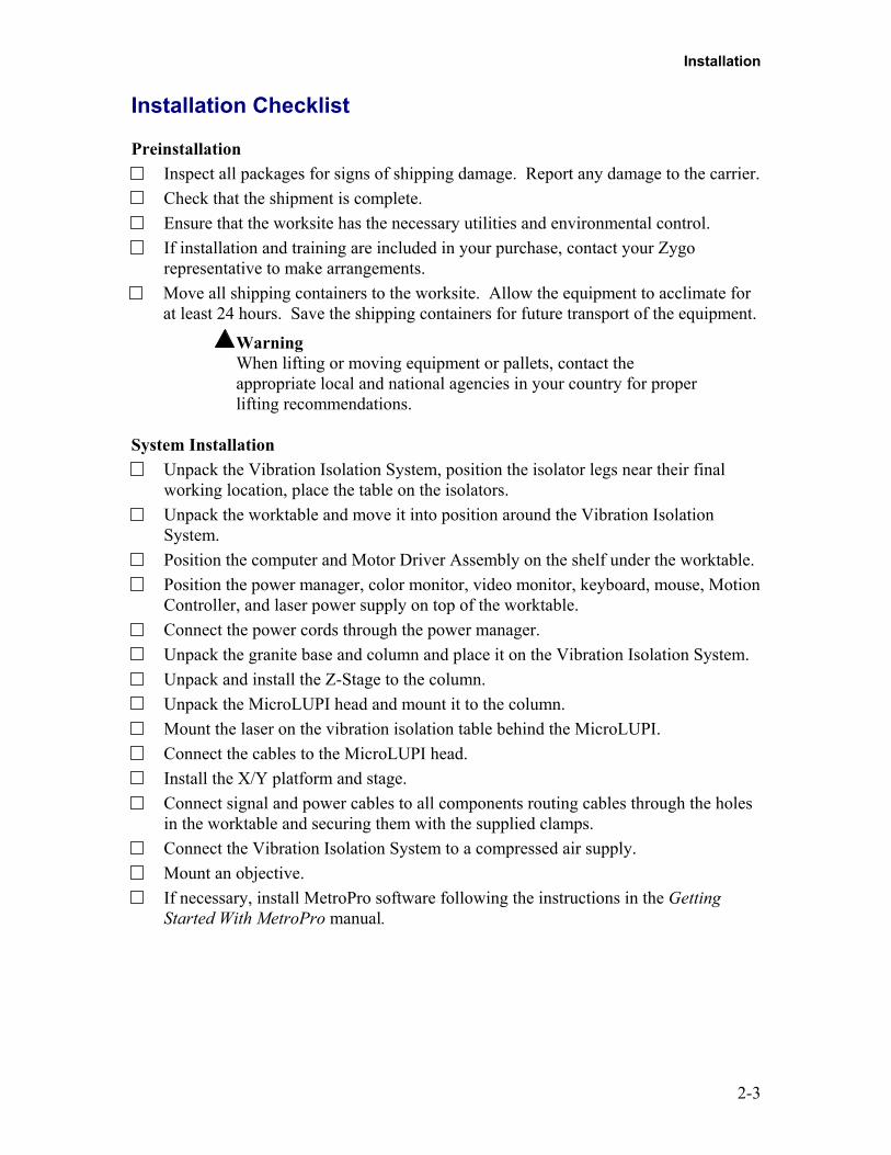
Installation Checklist
PreinstallationInspect all packages for signs of shipping damage. Report any damage to the carrier.Check that the shipment is complete.Ensure that the worksite has the necessary utilities and environmental control.If installation and training are included in your purchase, contact your Zygorepresentative to make arrangements.Move all shipping containers to the worksite. Allow the equipment to acclimate forat least 24 hours. Save the shipping containers for future transport of the equipment.
WarningWhen lifting or moving equipment or pallets, contact theappropriate local and national agencies in your country for properlifting recommendations.
System InstallationUnpack the Vibration Isolation System, position the isolator legs near their finalworking location, place the table on the isolators.Unpack the worktable and move it into position around the Vibration IsolationSystem.Position the computer and Motor Driver Assembly on the shelf under the worktable.Position the power manager, color monitor, video monitor, keyboard, mouse, MotionController, and laser power supply on top of the worktable.Connect the power cords through the power manager.Unpack the granite base and column and place it on the Vibration Isolation System.Unpack and install the Z-Stage to the column.Unpack the MicroLUPI head and mount it to the column.Mount the laser on the vibration isolation table behind the MicroLUPI.Connect the cables to the MicroLUPI head.Install the X/Y platform and stage.Connect signal and power cables to all components routing cables through the holesin the worktable and securing them with the supplied clamps.Connect the Vibration Isolation System to a compressed air supply.Mount an objective.If necessary, install MetroPro software following the instructions in the GettingStarted With MetroPro manual.
MicroLUPI
2-4
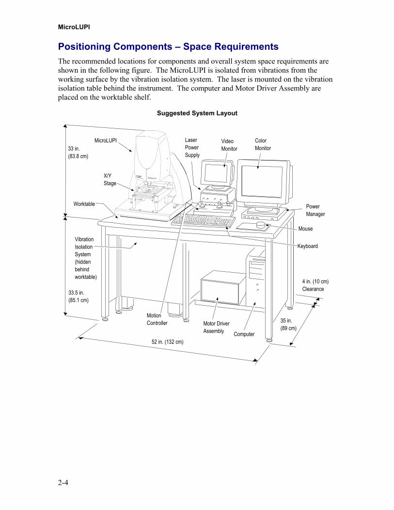
Positioning Components – Space RequirementsThe recommended locations for components and overall system space requirements areshown in the following figure. The MicroLUPI is isolated from vibrations from theworking surface by the vibration isolation system. The laser is mounted on the vibrationisolation table behind the instrument. The computer and Motor Driver Assembly areplaced on the worktable shelf.
Suggested System Layout
Motor DriverAssembly Computer
ColorMonitor
MotionController
VibrationIsolationSystem(hiddenbehindworktable)
Worktable
MicroLUPI
X/YStage
VideoMonitor
LaserPowerSupply
PowerManager
Mouse
Keyboard
4 in. (10 cm)Clearance
35 in.(89 cm)
52 in. (132 cm)
33 in.(83.8 cm)
33.5 in.(85.1 cm)

Installation
2-5
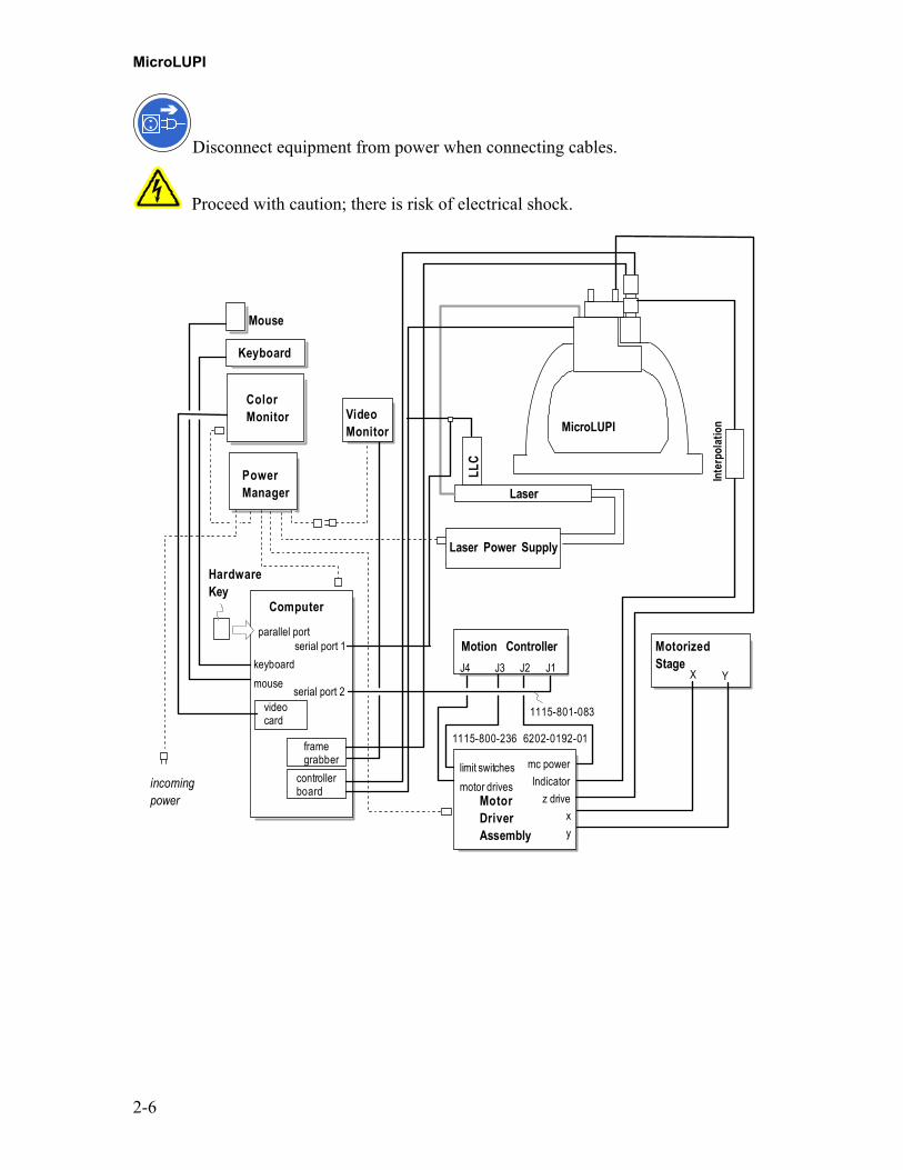
Cable ConnectionsThe computer connections shown in the following figure are for reference only; alwaysconsult the original equipment documentation.
WarningThe equipment must be electrically grounded through the supplyoutlet. The power manager is for power distribution for thesystem. Other equipment should not be connected to the powermanager.
The Hardware Key and the Controller Board cable have identicalconnectors. Make sure they are properly connected or theequipment may be damaged. The Hardware Key is connected tothe computer’s parallel port. The MicroLUPI cable is connected tothe Controller Board.
MicroLUPI
2-6
Disconnect equipment from power when connecting cables.
Proceed with caution; there is risk of electrical shock.
Motion ControllerJ4 J3 J2 J1
Computer
Keyboard
Mouse
HardwareKey
MotorizedStage
ColorMonitor
MotorDriverAssembly
parallel port
X Y
videocard
framegrabber mc power
Indicatorz drive
xy
limit switchesmotor drives
keyboardmouse serial port 2
6202-0192-01
1115-801-083
incomingpower
PowerManager
VideoMonitor
1115-800-236
MicroLUPI
controllerboard
Laser Power Supply
Laser
serial port 1
Inte
rpol
atio
n
LLC
Installation
2-7
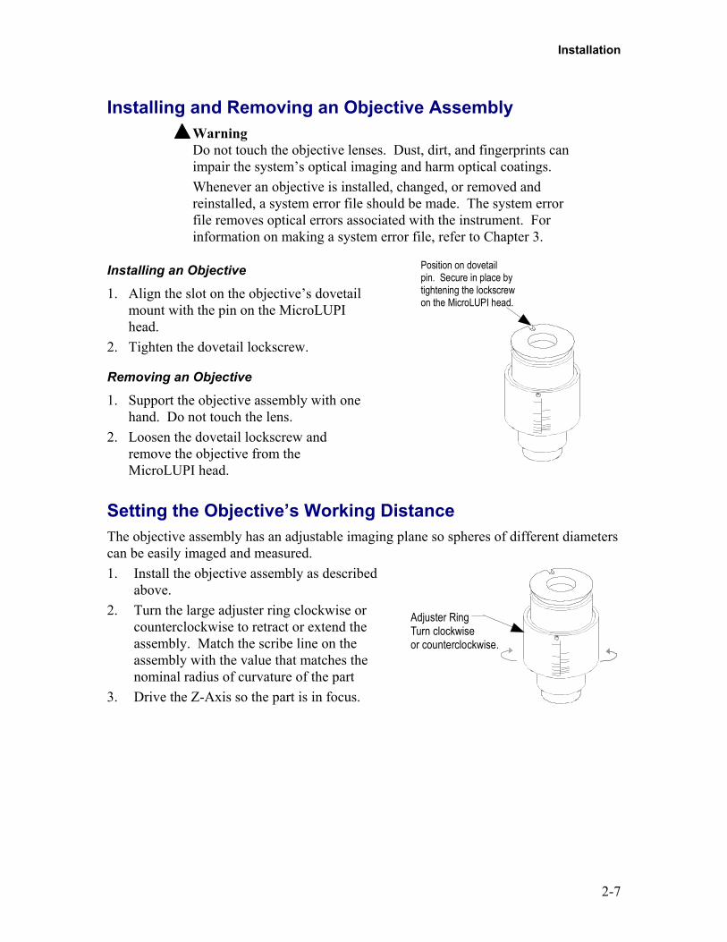
Installing and Removing an Objective AssemblyWarningDo not touch the objective lenses. Dust, dirt, and fingerprints canimpair the system’s optical imaging and harm optical coatings.Whenever an objective is installed, changed, or removed andreinstalled, a system error file should be made. The system errorfile removes optical errors associated with the instrument. Forinformation on making a system error file, refer to Chapter 3.
Installing an Objective
1. Align the slot on the objective’s dovetailmount with the pin on the MicroLUPIhead.
2. Tighten the dovetail lockscrew.
Removing an Objective
1. Support the objective assembly with onehand. Do not touch the lens.
2. Loosen the dovetail lockscrew andremove the objective from theMicroLUPI head.
Position on dovetailpin. Secure in place bytightening the lockscrewon the MicroLUPI head.
Setting the Objective’s Working DistanceThe objective assembly has an adjustable imaging plane so spheres of different diameterscan be easily imaged and measured.1. Install the objective assembly as described
above.2. Turn the large adjuster ring clockwise or
counterclockwise to retract or extend theassembly. Match the scribe line on theassembly with the value that matches thenominal radius of curvature of the part
3. Drive the Z-Axis so the part is in focus.
Adjuster RingTurn clockwiseor counterclockwise.
MicroLUPI
2-8
Leveling the Head to the X/Y StageThis procedure properly aligns the axes of the MicroLUPI head with the X/Y stage. Itshould be performed when the system is first installed. It can also be checked andverified as part of preventive maintenance, if desired.
Note: The hardware and software must be operational to perform thisprocedure. Refer to Chapter 3 for system power up instructions.
1. If an objective is installed,remove the objective.
2. Place a mirrored optical flaton the X/Y stage under theobjective area. If necessarydrive the stage to positionthe optical flat under thecollimated beam.
Note: A quality silicon carbideoptical flat is availablefrom Zygo Corp.
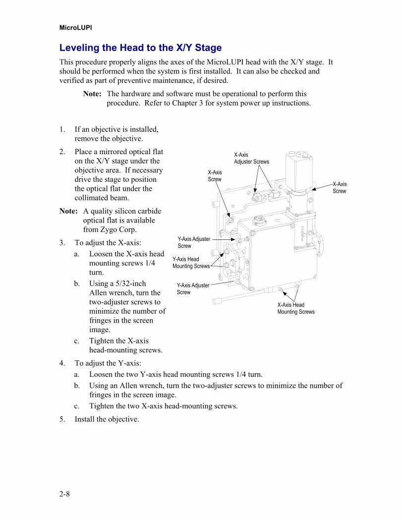
3. To adjust the X-axis:a. Loosen the X-axis head
mounting screws 1/4turn.
b. Using a 5/32-inchAllen wrench, turn thetwo-adjuster screws tominimize the number offringes in the screenimage.
c. Tighten the X-axishead-mounting screws.
X-AxisAdjuster Screws
X-AxisScrew
Y-Axis HeadMounting Screws
X-Axis HeadMounting Screws
Y-Axis AdjusterScrew
Y-Axis AdjusterScrew
X-AxisScrew
4. To adjust the Y-axis:a. Loosen the two Y-axis head mounting screws 1/4 turn.b. Using an Allen wrench, turn the two-adjuster screws to minimize the number of
fringes in the screen image.c. Tighten the two X-axis head-mounting screws.
5. Install the objective.

3-1
Making Measurements Chapter
3In This Chapter
• Note on MetroPro Documentation• Start-Up• Measurement Overview• Motion Controller Controls
- Using the Motion Controller• Light Level Controls
- The Light Level Window• Making and Using System Error Files• A Look at the MicroLUPI™ Application
– Home the Stage– Home the Z Axis– Using AutoNULL– Using AutoCalibrate– Setting Measurement Parameters– Making a Radius of Curvature Measurement– Defining a Measurement Pattern
• Shutdown
Note on MetroPro DocumentationMetroPro software is documented in separate manuals. For information on MetroProsoftware, and for software details not covered in this manual, refer to the manuals listedbelow.
Manual Description Source
Getting Started WithMetroPro, OMP-0398
How to install and use the basicfeatures of MetroPro.
Paper copyincluded.
MetroPro Reference Guide,OMP-0347
Listing and explanation, in adictionary format, of mostMetroPro’s features.
ZygoManual CD
MetroScript ProgrammingLanguage, OMP-0399
A user’s guide for MetroPro’sscripting language.
ZygoManual CD
MicroLUPI
3-2
A Note About OperationWarningThe operator must be trained before operating the system. Read alloperation instructions before starting the equipment. Theequipment should only be used in the manner in which it isintended.
Start-UpWarningThe operator is responsible for ensuring that the joysticks are notactivated when the system is first started. People and objects mustbe clear of the stage area. For emergencies, press the Motion Stopbutton to halt all stage motion.
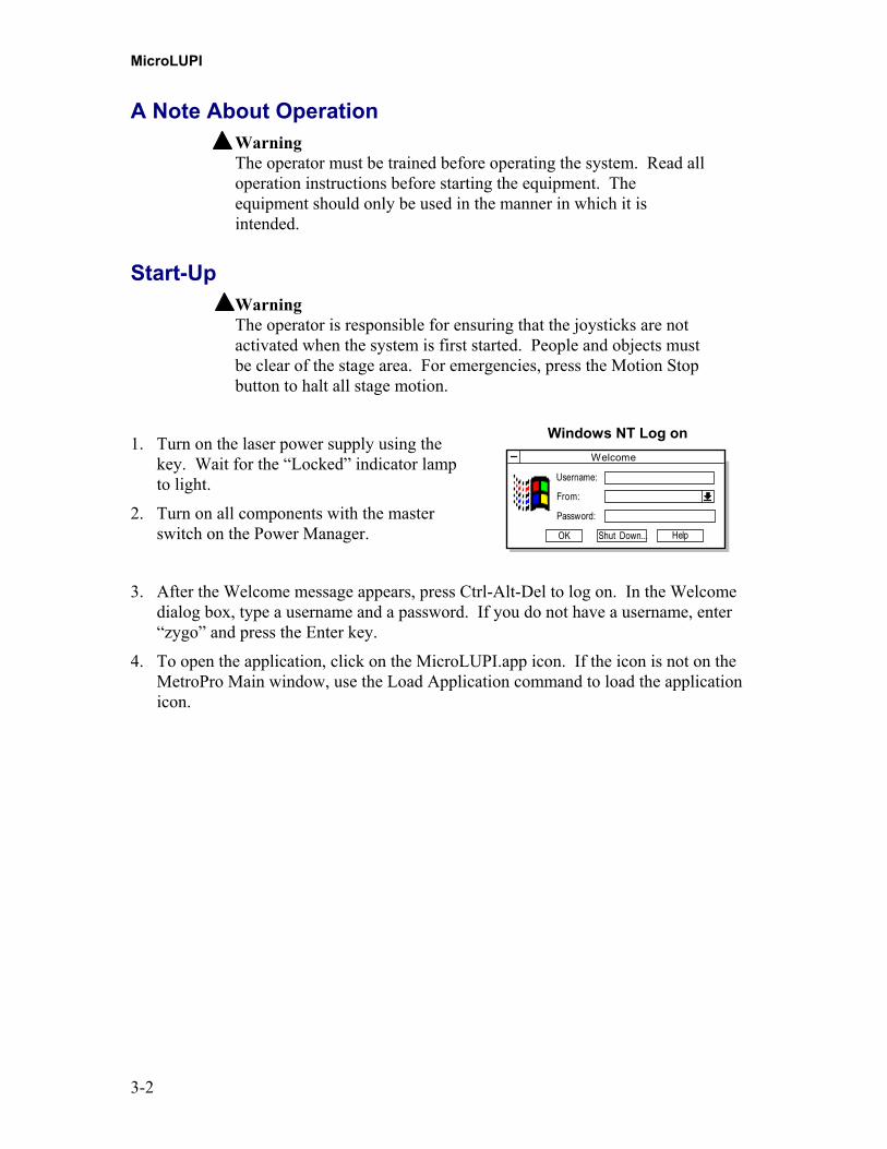
1. Turn on the laser power supply using thekey. Wait for the “Locked” indicator lampto light.
2. Turn on all components with the masterswitch on the Power Manager.
Windows NT Log on
Username:
From:
Password:
OK Shut Down... Help
Welcome
3. After the Welcome message appears, press Ctrl-Alt-Del to log on. In the Welcomedialog box, type a username and a password. If you do not have a username, enter“zygo” and press the Enter key.
4. To open the application, click on the MicroLUPI.app icon. If the icon is not on theMetroPro Main window, use the Load Application command to load the applicationicon.
Making Measurements
3-3
Location of Controls
Motor Driver Assembly Controls
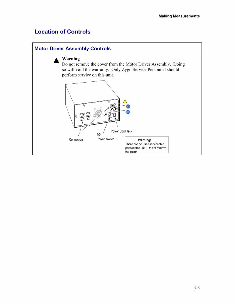
WarningDo not remove the cover from the Motor Driver Assembly. Doingso will void the warranty. Only Zygo Service Personnel shouldperform service on this unit.
Connectors1/0Power Switch
Power Cord Jack
There are no user-serviceableparts in this unit. Do not removethe cover.
Warning!
MicroLUPI
3-4
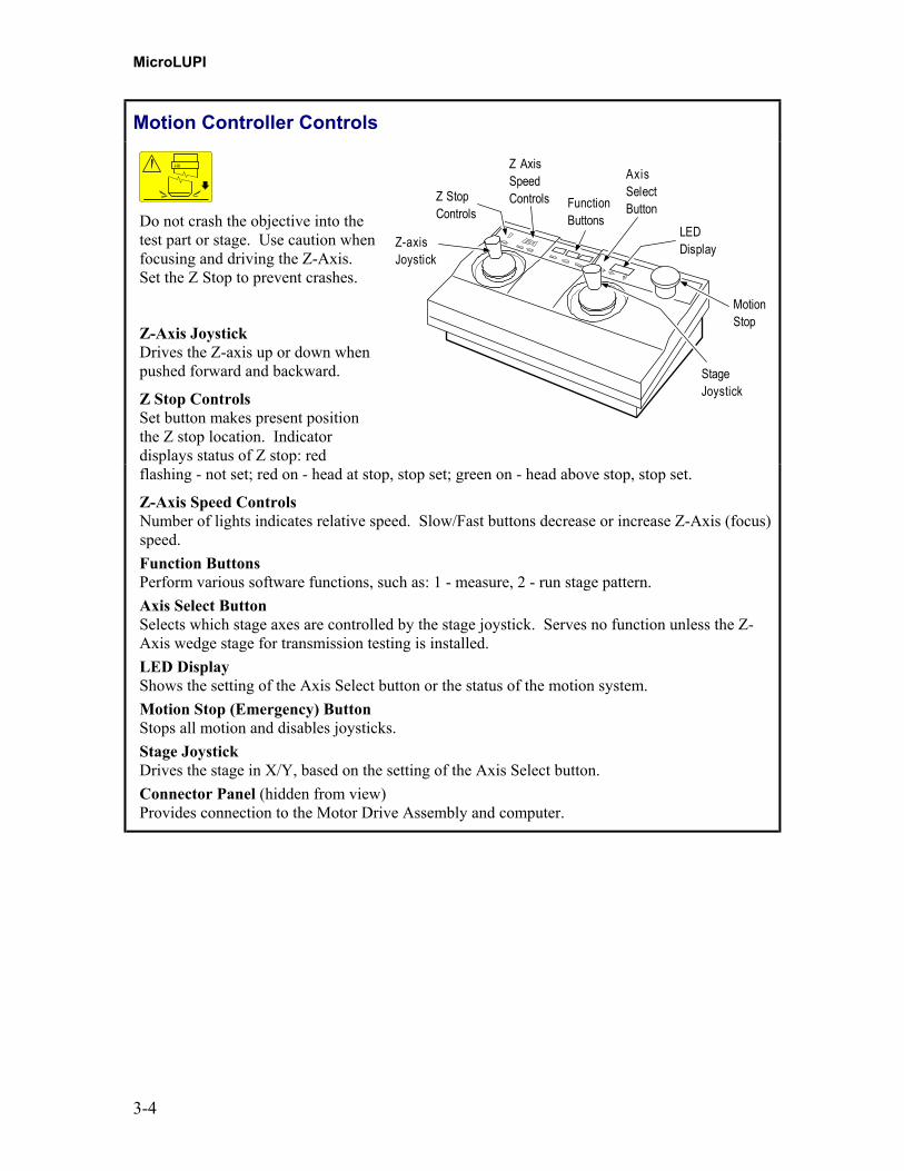
Motion Controller Controls
Do not crash the objective into thetest part or stage. Use caution whenfocusing and driving the Z-Axis.Set the Z Stop to prevent crashes.
Z-Axis JoystickDrives the Z-axis up or down whenpushed forward and backward.
Z Stop ControlsSet button makes present positionthe Z stop location. Indicatordisplays status of Z stop: red
Z StopControls
Z-axisJoystick
Z AxisSpeedControls Function
Buttons
MotionStop
StageJoystick
AxisSelectButton
LEDDisplay
flashing - not set; red on - head at stop, stop set; green on - head above stop, stop set.
Z-Axis Speed ControlsNumber of lights indicates relative speed. Slow/Fast buttons decrease or increase Z-Axis (focus)speed.Function ButtonsPerform various software functions, such as: 1 - measure, 2 - run stage pattern.Axis Select ButtonSelects which stage axes are controlled by the stage joystick. Serves no function unless the Z-Axis wedge stage for transmission testing is installed.LED DisplayShows the setting of the Axis Select button or the status of the motion system.Motion Stop (Emergency) ButtonStops all motion and disables joysticks.Stage JoystickDrives the stage in X/Y, based on the setting of the Axis Select button.Connector Panel (hidden from view)Provides connection to the Motor Drive Assembly and computer.

Making Measurements
3-5
Using The Motion ControllerThe Motion Controller is used formanually focusing the instrumentand driving the stage motors. Thetable below summarizes how to usethe Motion Controller.
Z STOP Z AXIS SPEED
SET SLOW FAST
FUNCTIONAXIS
SELECT
MOTIONSTOP1 2 3
Z-axis
X-axis
Y-axis
Operation How To
Drive Z-Axis
Push Z-axis (left) joystick to raise, pull to lower. Thegreater the deflection the faster the motion.
Do not crash the objective into the test part or stage.Use caution when focusing and driving the Z-Axis. Setthe Z Stop to prevent crashes.
Z-Axis speed Press SLOW (decrease) or FAST (increase).
Set Z Stop Lower head with Z-Axis joystick to slightly less thanobjective working distance; press SET.
Unset Z Stop Raise head with Z-Axis (left) joystick until the Z STOPindicator is green, then press SET.
Select stage axes Press AXIS SELECT repeatedly until the axes are shownin the display. [X Y] should be displayed.
Drive stage(controlling speed)
Move the stage (right) joystick.Up/Down for y-axis. Left/Right for x-axis. The greaterthe deflection the faster the motion.
Emergency Stop Press MOTION STOP to stop stage motion. Foremergency stop only.
Reset afterMOTION STOP pressed
Press and hold AXIS SELECT, turn MOTION STOPknob clockwise until it pops back up, and then release theAXIS SELECT button. Also click the Reset MC button inMetroPro.
MetroPro shortcuts Press 1 to Measure, Press 2 to Run Pattern,Press 3 to Focus.
MicroLUPI
3-6
Light Level ControlsThe MetroPro Light Level Window is used as a readout. The light level must be adjustedevery time the part changes.
Key Function
F4 Open Light Level Window to manually set light level.F5 Automatically set light level.
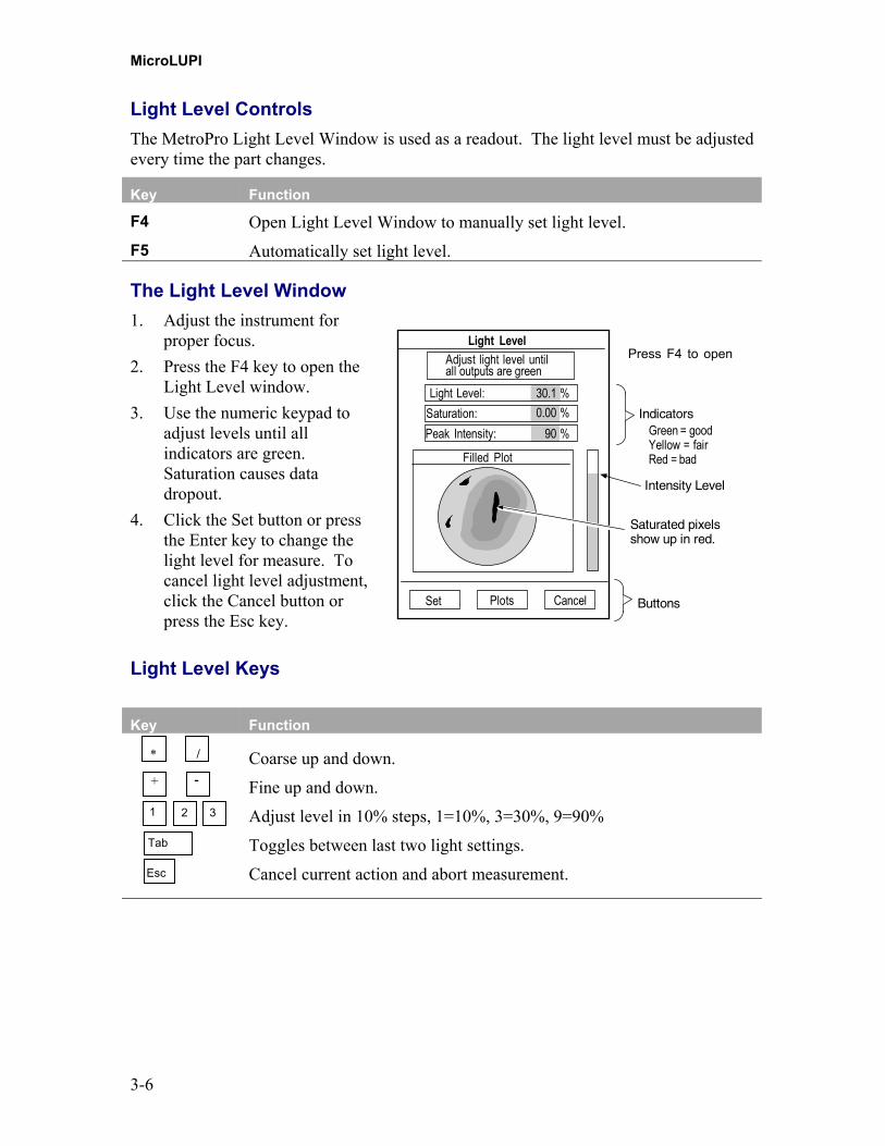
The Light Level Window1. Adjust the instrument for
proper focus.2. Press the F4 key to open the
Light Level window.3. Use the numeric keypad to
adjust levels until allindicators are green.Saturation causes datadropout.
4. Click the Set button or pressthe Enter key to change thelight level for measure. Tocancel light level adjustment,click the Cancel button orpress the Esc key.
Intensity Level
CancelPlots
Light Level
Saturation:Peak Intensity:
Filled Plot
90 %0.00 %
Light Level: 30.1 %
���������������������������������������������������������������������������������������������������������������������������������������������������������������������������������������������������������������������������������������
������������������������������������������������������������������������������������������������������������������������������������������������������������������������������������������
Saturated pixelsshow up in red.
Indicators
Adjust light level untilall outputs are green
Set
Green = goodYellow = fairRed = bad
Buttons
Press F4 to open
Light Level Keys
Key Function
Coarse up and down.
Fine up and down.
Adjust level in 10% steps, 1=10%, 3=30%, 9=90%
Toggles between last two light settings.
Cancel current action and abort measurement.
* /
+ -
1 2 3
Tab
Esc
Making Measurements
3-7
Making and Using System Error FilesSystem error files are used to subtract the systematic errors associated with theinstrument's optics to improve measurement accuracy. Zygo recommends that you usesystem error files for optimum measurement performance. Create a system error file bymeasuring a component of known high quality. Use a Zygo Reference Sphere whenusing an objective to measure radius of curvature. Use the Zygo silicon carbide opticalflat when measuring flat surfaces without an objective.
Make new system error files when:• Software changes in the Camera Mode control, or Phase Res control• Changes in the operating environment, especially temperature fluctuations• Removing and installing an objective.
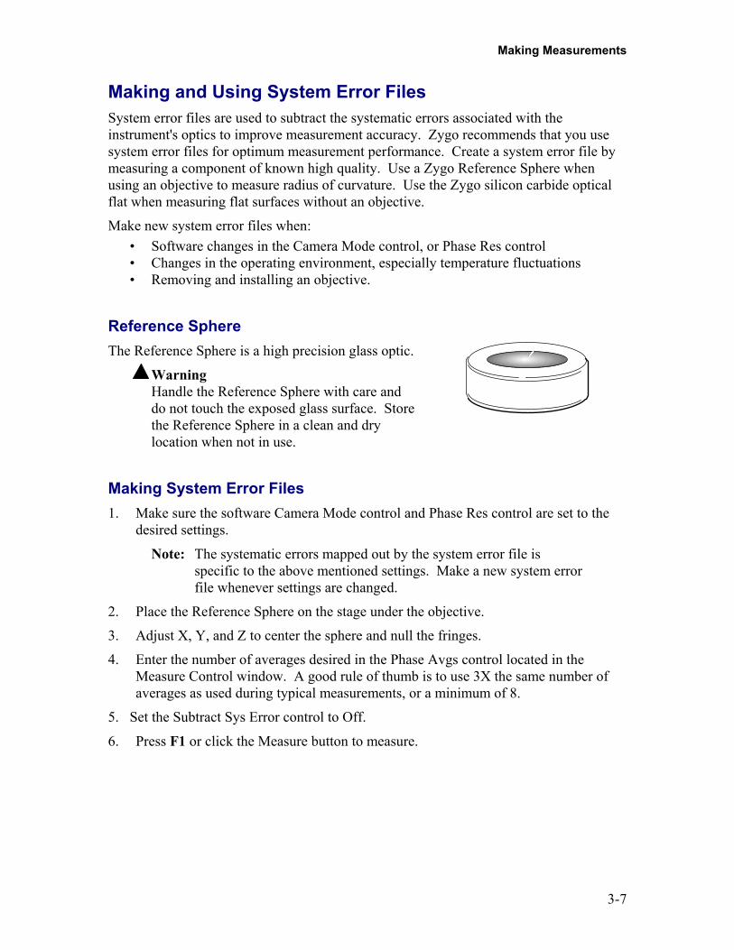
Reference SphereThe Reference Sphere is a high precision glass optic.
WarningHandle the Reference Sphere with care anddo not touch the exposed glass surface. Storethe Reference Sphere in a clean and drylocation when not in use.
Making System Error Files1. Make sure the software Camera Mode control and Phase Res control are set to the
desired settings.
Note: The systematic errors mapped out by the system error file isspecific to the above mentioned settings. Make a new system errorfile whenever settings are changed.
2. Place the Reference Sphere on the stage under the objective.
3. Adjust X, Y, and Z to center the sphere and null the fringes.
4. Enter the number of averages desired in the Phase Avgs control located in theMeasure Control window. A good rule of thumb is to use 3X the same number ofaverages as used during typical measurements, or a minimum of 8.
5. Set the Subtract Sys Error control to Off.
6. Press F1 or click the Measure button to measure.

MicroLUPI
3-8
7. Click the Save Data button. In the File Handler, click the "Current Selection" box,enter a name for the reference error file, ending with ".dat" and press Enter, thenclick the Done button to close the File Handler.
Note: Try to use a naming convention that you will recognize, such asthat shown below. The default directory for storing system errorfiles is "C:\Users\Zygo\MetroPro\Apps".
SysErrLN1x.dat
Camera ModeL - 320x240H - 640x480
Zoom SettingPhase ResN - normalH - high
Using System Error Files1. Click the Measure Cntrl button.
2. Click the Subtract Sys Err control to set it to On.
4. Click the Sys Err File control and enter the name of the system error file thatmatches your software and instrument settings, then press Enter.
Making Measurements
3-9
Measurement Overview (Spherical Part)(Additional information is provided in the MicroLUPI Application section of this chapter.Be sure to review the following Objective Crash Protection procedure before beginning ameasurement sequence.)
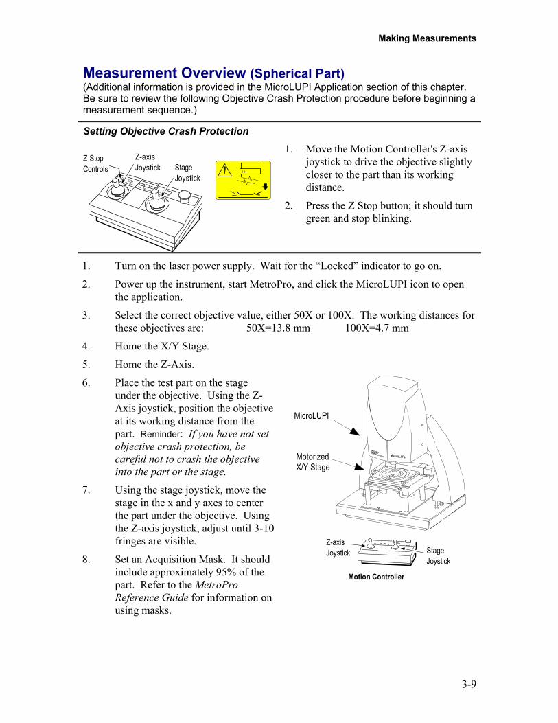
Setting Objective Crash Protection
Z StopControls
Z-axisJoystick Stage
Joystick
1. Move the Motion Controller's Z-axisjoystick to drive the objective slightlycloser to the part than its workingdistance.
2. Press the Z Stop button; it should turngreen and stop blinking.
1. Turn on the laser power supply. Wait for the “Locked” indicator to go on.
2. Power up the instrument, start MetroPro, and click the MicroLUPI icon to openthe application.
3. Select the correct objective value, either 50X or 100X. The working distances forthese objectives are: 50X=13.8 mm 100X=4.7 mm
4. Home the X/Y Stage.
5. Home the Z-Axis.
6. Place the test part on the stageunder the objective. Using the Z-Axis joystick, position the objectiveat its working distance from thepart. Reminder: If you have not setobjective crash protection, becareful not to crash the objectiveinto the part or the stage.
7. Using the stage joystick, move thestage in the x and y axes to centerthe part under the objective. Usingthe Z-axis joystick, adjust until 3-10fringes are visible.
8. Set an Acquisition Mask. It shouldinclude approximately 95% of thepart. Refer to the MetroProReference Guide for information onusing masks.
MicroLUPI
MotorizedX/Y Stage
Motion Controller
Z-axisJoystick Stage
Joystick

MicroLUPI
3-10
9. Toggle either AutoNULL Power or AutoNULL Focus on.
10. Click the Auto Calibrate button. Verify that the fit quality numbers are good.This number should be as close to 1 as possible.
11. Enter a value for Lateral Pass Limit and a value for either Power Pass Limit orFocus Pass Limit.
12. Click the AutoNULL button.
13. Press the F1 key or click the MEASURE button to make the measurement.
The MicroLUPI ApplicationThis is a typical display for the MicroLUPI Application including a sample data set.Buttons, controls, and results specific to this application are described below. Forinformation on all other items shown on this screen which are not described in thischapter, refer to the MetroPro Reference Guide, OMP-0347.
These buttons and controls are described in this chapter. All other items on theMicroLUPI screen are covered in the MetroPro Reference Guide.

Making Measurements
3-11
Click to activatethe function.
Home StageEstablishes a reference start position for the X/Y Stage. Home Stageshould be done each time the system is powered on.Home Z AxisEstablishes a beginning travel position for the Z-Axis head. Before usingthis function, the Motion Controller Z Stop control must be in the setposition (red).
Click to activatethe function.
Auto Null ButtonInitiates the Auto Null routine. Set values for the correspondingparameters. See MicroLUPI Controls for usage information on AutoNull.Measure Radius ButtonMeasures the Radius of Curvature of a part. Set values for thecorresponding parameters. See MicroLUPI Controls for usageinformation on Measure Radius.Auto Calibrate ButtonBegins the Auto Calibrate Routine. Set values for the correspondingparameters. See MicroLUPI Controls for usage information on AutoCalibrate.Radius Calibrate ButtonBegins the Radius Calibrate routine. This function establishes the radiusof curvature calibration factor. The system automatically updates thecorresponding .cfg file in the working directory. The Radius Calibrationstandard is used for this procedure. Refer to the “Measuring the RadiusCalibration Standard” section of this chapter.
MicroLUPI ControlsWindow
AutoNULL Power: On(AutoNULL Focus: Off)
Provide values for:
Lateral Pass Limit Power Pass Limit
AutoNull ProcessDesigned to minimize tilt magnitude and establish limitsfor the removal of either power or defocus. Several parametersmust be set for this feature to function correctly.
AutoNULL Focus: On(AutoNULL Power: Off)
Provide values for:
Lateral Pass Limit Focus Pass Limit
Precision AutoNULL can be ON at thesame time as either AutoNULL Power orAutoNULL Focus. The Precision featureadds 5 extra attempts to the software routine.
Important! Run Auto Calibrate before using AutoNULL as AutoCalibrate establishes the X, Y, and Z Calibration factors.
MicroLUPI
3-12
AutoNULL PowerThe Z calibration factors and the Lateral Pass Limit values are used to adjust part positioning.The Z-Axis head is moved to find the optimum location for fringes and power. The X/Y Stage ismoved to minimize the number of tilt fringes.
When using AutoNULL Power, set these parameters:• Click on Power Pass Limit. (This value identifies the maximum number of waves of power.) •Type a value and press Enter.• Click on Lateral Pass Limit. Type a value and press Enter. This value identifies the maximum number of waves of tilt that can be allowed in the measurement.AutoNULL FocusThe Z calibration factors and the Lateral Pass Limit values are used to adjust partpositioning. The Z-Axis head is moved to find the optimum location for fringes andfocus. The X/Y Stage is moved to minimize the number of tilt fringes.Click on Lateral Pass Limit. Enter a value and press Enter.This control specifies the maximum number of waves of tilt that can be allowed in themeasurement.Click on Focus Pass Limit. Enter a value and press Enter. This control specifies themaximum number of waves of defocus that can be allowed in the measurement.
Radius Measurement ParametersMeasure RadiusThis is a toggle that is either on or off. When it is on and a pattern is used, MeasureRadius is activated automatically, and the radius of curvature of the part is measured.Radius of Curvature is defined as the distance from the surface (or its best-fit sphericalequivalent) to the center of curvature. The system automatically measures both theconfocal and cat’s eye positions. These measurements are used to calculate slight partpositioning (null or focus) errors and eliminate them from the radius measurement.Nominal RadiusClick on this control and enter the nominal radius value. Press Enter.
Auto Calibrate ParametersThe calibrate routine establishes the lateral measurement resolution of each camera pixel.This process provides a reference dimension with which to compute lateral dimensionseen by each pixel of the instrument’s camera. Calibration is covered in more detail in“Chapter 7” of the MetroPro Reference Guide.Auto Cal X/Y stepSpecifies the distance to step in the X and Y axes during auto calibration. Use the defaultvalues.Auto Cal Z stepSpecifies the distance to step in the Z-Axis during auto calibration. Use the defaultvalues.

Making Measurements
3-13
Measuring the Radius Calibration Standard1. Select the correct objective value, either 50X or
100X.
2. Home the X/Y Stage.
3. Home the Z Axis.
4. Place the Radius Calibration Standard on the stage.The small pin on the bottom of the standard fits intothe slot in the center of the stage.
Radius Calibration Standard
5. Using the stage joystick, center the standard under the objective. There should befringes on the monitor. Adjust in the Z Axis until there are between 3 and 10fringes.
6. Create a circular acquisition mask over 95% of the surface.
7. Click either AutoNULL Focus or AutoNULL Power.
8. Click the Auto Calibrate button.
9. Click on Lateral Pass Limit and enter a value. Press Enter.
10. Click on either Focus or Power Pass Limit, enter a value, and press Enter
11. Click the AutoNULL button.
12. Click on Nominal Radius and enter the standard’s actual radius value. Press Enter.
13. Click on the Radius Calibrate button.
The Light Level Window will open automatically. Adjust for proper light level.
14. Use the numeric keypad to adjust levels until all indicators are green. Saturationcauses data dropout. Click the Set button or press the Enter key to change the lightlevel for measure. To cancel light level adjustment, click the Cancel button or pressthe Esc key.
15. Click yes to set the radius calibration factor.
MicroLUPI
3-14
Using the Pattern EditorThe Pattern Editor function is used for creating, editing, saving and loading stage controlpattern files. Pattern files direct the movement of programmable stages. The informationin this section is an overview of Pattern Editor operation. Refer to “Chapter 8” in theMetroPro Reference Guide for a complete explanation.
Sample Steps for Creating a Pattern1. Click the Pattern Cntrl button (on the left side of the MicroLUPI Main Window) to
open the Pattern Editor.
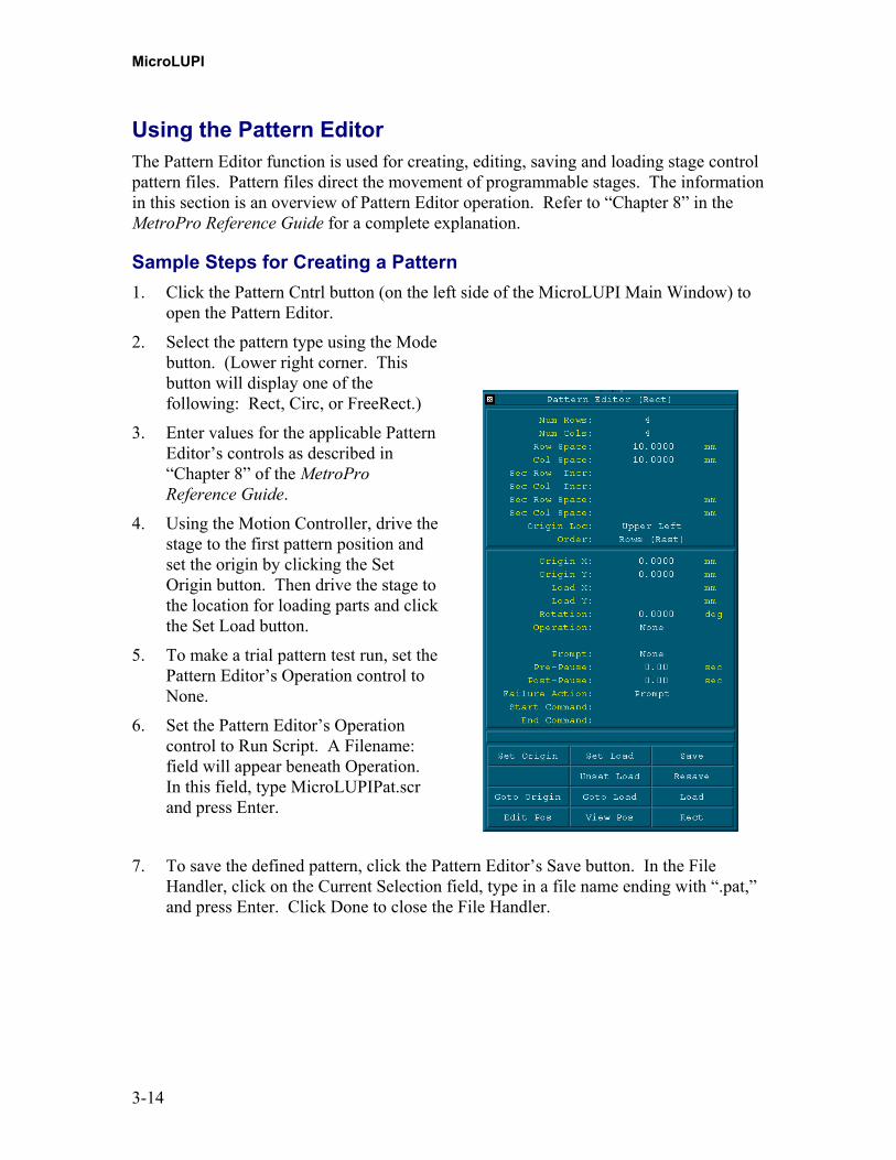
2. Select the pattern type using the Modebutton. (Lower right corner. Thisbutton will display one of thefollowing: Rect, Circ, or FreeRect.)
3. Enter values for the applicable PatternEditor’s controls as described in“Chapter 8” of the MetroProReference Guide.
4. Using the Motion Controller, drive thestage to the first pattern position andset the origin by clicking the SetOrigin button. Then drive the stage tothe location for loading parts and clickthe Set Load button.
5. To make a trial pattern test run, set thePattern Editor’s Operation control toNone.
6. Set the Pattern Editor’s Operationcontrol to Run Script. A Filename:field will appear beneath Operation.In this field, type MicroLUPIPat.scrand press Enter.
7. To save the defined pattern, click the Pattern Editor’s Save button. In the FileHandler, click on the Current Selection field, type in a file name ending with “.pat,”and press Enter. Click Done to close the File Handler.
Making Measurements
3-15
8. Click the Auto Load Pattern control to On. Enter the name of the pattern in thePattern File Control.
9. Save changes to the application. If it is an application from Zygo, select the SaveApplication command from the Application Window menu. In the File Handler,enter a name for the file, ending with “.app,” and press Enter. Click the Donebutton.
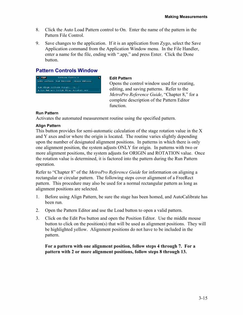
Pattern Controls WindowEdit PatternOpens the control window used for creating,editing, and saving patterns. Refer to theMetroPro Reference Guide, “Chapter 8,” for acomplete description of the Pattern Editorfunction.
Run PatternActivates the automated measurement routine using the specified pattern.Align PatternThis button provides for semi-automatic calculation of the stage rotation value in the Xand Y axes and/or where the origin is located. The routine varies slightly dependingupon the number of designated alignment positions. In patterns in which there is onlyone alignment position, the system adjusts ONLY for origin. In patterns with two ormore alignment positions, the system adjusts for ORIGIN and ROTATION value. Oncethe rotation value is determined, it is factored into the pattern during the Run Patternoperation.
Refer to “Chapter 8” of the MetroPro Reference Guide for information on aligning arectangular or circular pattern. The following steps cover alignment of a FreeRectpattern. This procedure may also be used for a normal rectangular pattern as long asalignment positions are selected.
1. Before using Align Pattern, be sure the stage has been homed, and AutoCalibrate hasbeen run.
2. Open the Pattern Editor and use the Load button to open a valid pattern.
3. Click on the Edit Pos button and open the Position Editor. Use the middle mousebutton to click on the position(s) that will be used as alignment positions. They willbe highlighted yellow. Alignment positions do not have to be included in thepattern.
For a pattern with one alignment position, follow steps 4 through 7. For apattern with 2 or more alignment positions, follow steps 8 through 13.
MicroLUPI
3-16
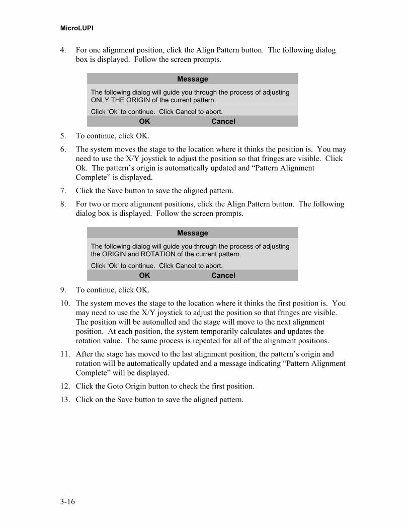
4. For one alignment position, click the Align Pattern button. The following dialogbox is displayed. Follow the screen prompts.
Message
The following dialog will guide you through the process of adjustingONLY THE ORIGIN of the current pattern.
Click ‘Ok’ to continue. Click Cancel to abort.OK Cancel
5. To continue, click OK.
6. The system moves the stage to the location where it thinks the position is. You mayneed to use the X/Y joystick to adjust the position so that fringes are visible. ClickOk. The pattern’s origin is automatically updated and “Pattern AlignmentComplete” is displayed.
7. Click the Save button to save the aligned pattern.
8. For two or more alignment positions, click the Align Pattern button. The followingdialog box is displayed. Follow the screen prompts.
Message
The following dialog will guide you through the process of adjustingthe ORIGIN and ROTATION of the current pattern.
Click ‘Ok’ to continue. Click Cancel to abort.OK Cancel
9. To continue, click OK.
10. The system moves the stage to the location where it thinks the first position is. Youmay need to use the X/Y joystick to adjust the position so that fringes are visible.The position will be autonulled and the stage will move to the next alignmentposition. At each position, the system temporarily calculates and updates therotation value. The same process is repeated for all of the alignment positions.
11. After the stage has moved to the last alignment position, the pattern’s origin androtation will be automatically updated and a message indicating “Pattern AlignmentComplete” will be displayed.
12. Click the Goto Origin button to check the first position.
13. Click on the Save button to save the aligned pattern.
Making Measurements
3-17
Run Align Pattern ScriptWhen on, the script file specified below is activated during the align pattern routine.This control should be on.Align Pattern Script FileSpecifies the filename of the script that should run during the pattern alignmentprocedure. Do not delete or change the AutoNULL.scr file name.
Frequently Used MicroLUPI Software OperationsOperation How To …
Save data Click the Save Data button. In the File Handler, click the CurrentSelection box, enter a name for the file, ending with “.dat,” and pressEnter. Then click Done.
Print results Click the word “zygo” in the window you want to print, orselect the Print command from the window’s menu. In the PrintPanel, click the Print button.
Save changes made tocontrols, plots, results,and windows
You must save the application under a new name. Select theSave Application command from the Application Windowmenu. In the File Handler, click the Current Selection box,enter a name for the file, ending with “.app” and press Enter.Then click Done.
Define a mask Click the Mask Data button. Use the Mask Editor to defineareas to include or exclude from the test part measurement. See“Chapter 7” of the MetroPro Reference Guide.
Turn off the System Warning! Improper shutdown can damage the instrument.Select the Quit command from the MetroPro menu; turn offpower after you have shut down from within Windows. See the“Shut Down” section of this chapter.
MicroLUPI
3-18
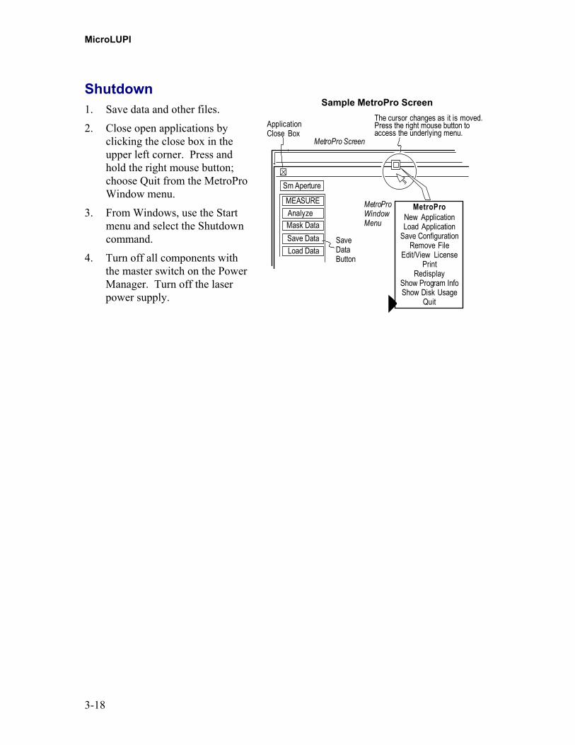
Shutdown1. Save data and other files.
2. Close open applications byclicking the close box in theupper left corner. Press andhold the right mouse button;choose Quit from the MetroProWindow menu.
3. From Windows, use the Startmenu and select the Shutdowncommand.
4. Turn off all components withthe master switch on the PowerManager. Turn off the laserpower supply.
Sample MetroPro Screen
Sm Aperture
The cursor changes as it is moved.Press the right mouse button toaccess the underlying menu.
MetroProWindowMenu
MetroPro Screen
MEASUREAnalyzeMask DataSave DataLoad Data
MetroProNew ApplicationLoad Application
Save ConfigurationRemove File
Edit/View LicensePrint
RedisplayShow Program InfoShow Disk Usage
Quit
ApplicationClose Box
SaveDataButton

4-1
Measurement Types Chapter
4In This Chapter
• Choosing the Right Objective• Surface Reflection Measurement• Radius of Curvature Measurement
Choosing the Right ObjectiveTo successfully use the MicroLUPI to measure parts, it is necessary to understand somebackground information about objectives and spherical elements. The objective is usedto transform the collimated output beam of the instrument into a spherical wavefront.Zygo Corp. offers various objectives to accommodate a range of concave and convex testparts. Objectives are specified by numerical aperture (NA).
Background Information - What is NA?
The objective’s Numerical Aperture (N.A.) is a term representative of the angle includedby a cone of light accepted by the objective. The higher the N.A., the greater theresolving power and the larger the part diameter that can be measured.
LightCone
σ
A A
The numerical aperture of an objective is a measure of itsability to gather light and resolve fine part detail at a fixedobject distance. Image-forming light waves from the testpart enter the objective in an inverted cone. A longitudinalslice of this cone of light shows the angular aperture (A), avalue that is determined by the focal length of the objective.
The angle σ is one-half the angular aperture (A) and isrelated to the numerical aperture through the followingequation:
Numerical Aperture (NA) = n (sin σ)
Where n is the refractive index of the imaging medium between the front lens of theobjective and the test part, which is a value of 1.00 for air. Since the refractive index ofair is 1.0, the numerical aperture is dependent only upon the angle σ whose maximumvalue is 90°. The theoretical maximum numerical aperture of a lens operating with air asthe imaging medium is 1.0 [NA = 1 (sin 90°)].

MicroLUPI
4-2
In practice, however, itis difficult to achievenumerical aperturevalues above 0.95 withobjectives used in air.The examples shownhere illustrate a series oflight cones derived fromobjectives of varyingfocal length andnumerical aperture.
σ
A A
σA A
NA = n (sin σ)
σA A
σ = 7° NA = 0.12 σ = 20° NA = 0.34 σ = 60° NA = 0.87
Determining the NA of the Test Optic
The NA of the test optic must bematched to the NA of the objective. Tocalculate the NA of the test optic youhave to know the clear aperture andnominal radius of curvature.
The NA of the objective must begreater than or equal to the NA of theoptic under test.
CA (clearaperture)
R(radius ofcurvature)
σ
Sinσ = CA2R = NA
MicroLUPI Objective Specifications
Objective NA Working Distance
50X 0.45 13.80 mm
100X 0.73 4.70 mm
Measurement Constraints
To measure the entire surface of aspherical test part, the cone of lightfrom the objective must be largeenough to completely fill the testpart. The objective NA must beequal to or larger than the NA of thetest part.
Concave PartObjective NA ≥ Part NA
Convex PartObjective NA ≥ Part NA
Measurement Types
4-3
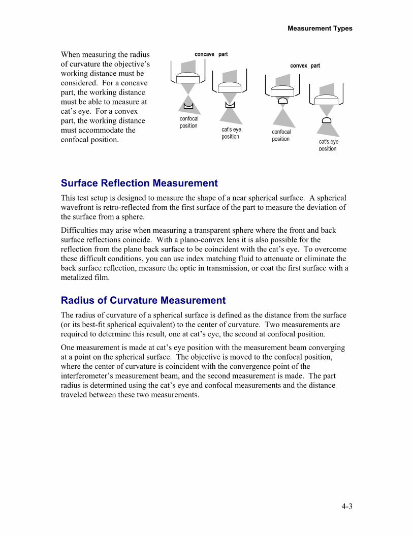
When measuring the radiusof curvature the objective’sworking distance must beconsidered. For a concavepart, the working distancemust be able to measure atcat’s eye. For a convexpart, the working distancemust accommodate theconfocal position.
confocalposition cat's eye
position
concave part
cat's eyeposition
confocalposition
convex part
Surface Reflection MeasurementThis test setup is designed to measure the shape of a near spherical surface. A sphericalwavefront is retro-reflected from the first surface of the part to measure the deviation ofthe surface from a sphere.
Difficulties may arise when measuring a transparent sphere where the front and backsurface reflections coincide. With a plano-convex lens it is also possible for thereflection from the plano back surface to be coincident with the cat’s eye. To overcomethese difficult conditions, you can use index matching fluid to attenuate or eliminate theback surface reflection, measure the optic in transmission, or coat the first surface with ametalized film.
Radius of Curvature MeasurementThe radius of curvature of a spherical surface is defined as the distance from the surface(or its best-fit spherical equivalent) to the center of curvature. Two measurements arerequired to determine this result, one at cat’s eye, the second at confocal position.
One measurement is made at cat’s eye position with the measurement beam convergingat a point on the spherical surface. The objective is moved to the confocal position,where the center of curvature is coincident with the convergence point of theinterferometer’s measurement beam, and the second measurement is made. The partradius is determined using the cat’s eye and confocal measurements and the distancetraveled between these two measurements.

MicroLUPI
4-4

5-1
Maintenance Chapter
5In This Chapter
• A Note About Maintenance• General Care• Maintenance and Care for Computer Components• Maintenance and Care for the MicroLUPI
- Cleaning of External Surfaces- Cleaning Optics- Recommended Optical Cleaning Procedures
• Servicing the MicroLUPI
General CareThe components used in the MicroLUPI system will provide many years of service withlittle maintenance if a few guidelines are observed:
• Keep the Environment CleanThe working environment should be as clean, dry, and as dust-free as possible.Occasionally clean painted surfaces and covers by wiping with a cloth dampenedwith a mild cleaning solution.
• Handle Objectives CarefullyObjectives are precision optics. Handle objectives only when necessary. Keepunused objectives stored in their protective containers. Do not clean objectivesunless you have experience cleaning optics.
• Do Not Disassemble ComponentsDo not attempt to remove component covers, dismantle optical parts or repaircircuit boards since system performance may be impaired. There are no user-serviceable internal parts.
• Contact Zygo Customer Support Center or Your Zygo RepresentativeCall Zygo or your Zygo representative if you have questions or problems.
MicroLUPI
5-2
Maintenance and Care for Computer ComponentsRefer to the original manufacturer’s documentation for maintenance information for thecomputer components, which includes the computer, color display, mouse, keyboard, andany accessories, such as a printer.
If you are experiencing problems, but are not sure of the cause, contact Zygo.
Maintenance and Care for the MicroLUPIMicroLUPI components require minimal upkeep. For details, refer to the followingsections. Recommended maintenance items are listed below.
Maintenance Schedule
Maintenance Frequency
Clean exterior surfaces of equipment. As needed, based on the operatingenvironment.
Clean optics (objectives). As needed; only when dirty.
Cleaning of External SurfacesOccasionally clean the painted surfaces of the equipment and covers by wiping with acloth dampened, but not wet, with a mild cleaning solution.
Cleaning OpticsCleaning of any precision optic risks degrading the surface. All the cleanable objectivelens surfaces are coated. Coated optics are easily damaged by improper or unnecessarycleaning. The need for cleaning can be minimized by proper handling techniques,returning the objectives to their plastic case when not in use, and by keeping theenvironment clean.
Do not attempt to clean optics within the instrument head since system performance maybe impaired.
Recommended Cleaning Materials:
• Polyethylene lab glovesWear to prevent contamination of surfaces and protect the skin against harshchemicals.
• Compressed gas with blower nozzleUse to blow off dust and lint from the optic.
• Lens tissue Use when it is necessary to clean an optical surface. The lens tissue should beoptics grade.
Maintenance
5-3
• Cotton swabsUse to clean difficult to reach surfaces. The swabs should have wood or paperstems; plastic stems can dissolve in acetone.
• SolventsUse spectroscopic grade isopropyl alcohol and methanol to remove contaminatesfixed to the optical surface. Use a mild, neutral 1% soap solution or lens cleanerto remove oily contaminates.
Recommended Optic Cleaning ProceduresWarning
• Be careful when using isopropyl alcohol and methanol; both areflammable and toxic.
• Do not reuse any cleaning tissue or pads, reusing tissues can causecontamination and damage to the optic.
• Before cleaning optics, remove all rings and jewelry from yourhands and wrists; wash your hands thoroughly to remove excessskin oils; and put on lab gloves.
Optics Cleaning Procedures
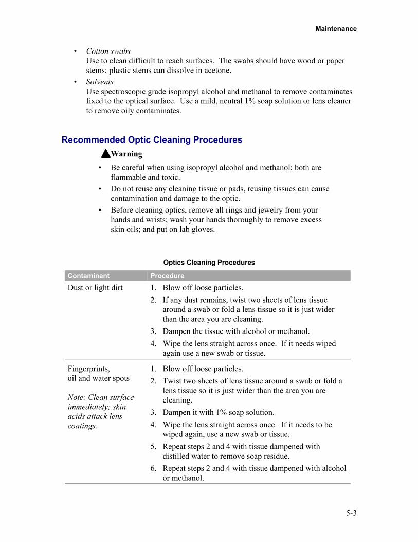
Contaminant ProcedureDust or light dirt 1. Blow off loose particles.
2. If any dust remains, twist two sheets of lens tissuearound a swab or fold a lens tissue so it is just widerthan the area you are cleaning.
3. Dampen the tissue with alcohol or methanol.4. Wipe the lens straight across once. If it needs wiped
again use a new swab or tissue.
Fingerprints,oil and water spots
Note: Clean surfaceimmediately; skinacids attack lenscoatings.
1. Blow off loose particles.2. Twist two sheets of lens tissue around a swab or fold a
lens tissue so it is just wider than the area you arecleaning.
3. Dampen it with 1% soap solution.4. Wipe the lens straight across once. If it needs to be
wiped again, use a new swab or tissue.5. Repeat steps 2 and 4 with tissue dampened with
distilled water to remove soap residue.6. Repeat steps 2 and 4 with tissue dampened with alcohol
or methanol.
MicroLUPI
5-4
Servicing the MicroLUPIWarningThe equipment does not have any user-serviceable components.Service must be performed by Zygo Corporation trained servicepersonnel. Any attempt to service or repair equipment may voidthe warranty.
Components have been selected for conformance to applicable industry standards, allreplacement parts must be approved by Zygo Corporation. Contact your ZygoCorporation representative for service.
For service on the computer equipment, refer to the original manufacturer’sdocumentation.
Returning Equipment to ZygoTo return equipment to Zygo Corporation, it is necessary to have an RA (returnauthorization) number. Contact Zygo Corporation for an RA number and instructions onpacking and shipping the equipment.
Note: Do not return equipment to Zygo without an RA number.Equipment returned without an RA number is not accepted.

Index
OMP-0448 page 1
AAir Supply Requirements, 2-3Air Turbulence, 2-2Airborne Impurities, 2-2Align Pattern Script File, 3-16Align Pattern, 3-14Alignment Positions, 3-14Aperture Label, 1-9Auto Cal X/Y Step, 3-11Auto Cal Z Step, 3-11Auto Calibrate Button, 3-10Auto Calibrate Parameters, 3-9Auto Null,
Button, 3-10Description of, 3-10Focus Control, 3-11Parameters for, 3-9Power Control, 3-11
Axis Select Button, 3-4
BBeamsplitter, 1-3
CCable Connections, 2-5Cat’s Eye Position, 4-3CE Labels, 1-11Certification Label, 1-9Class II Laser Warning, 1-9Cleaning Optics, 5-2Computer Maintenance, 5-2Confocal position, 4-3Controlling Speed, 3-5Creating a Pattern, 3-13
DDefine a Mask, 3-16Disconnect Power Label, 1-11
EEarth Ground Label, 1-11Edit Pattern, 3-14Electrical Shock Hazard Label, 1-11Electrical Supply Requirements, 2-2Emergency Stop Button, 3-4Equipment Labels,
see CE Labels, Laser Safety
FFocus Joystick, 1-6Focus Pass Limit Control, 3-11Function Buttons, 3-4
GGeneral Hazard Label, 1-11
HHardware Key, 1-7Home Stage, 3-10Home Z Axis, 3-10Hot Surface Label, 1-11
IIdentification Label, 1-9Installation,
Checklist for, 2-3Objective Assembly, 2-7Warning Notice for, 2-1
JJoystick Controls, 3-3
KKeyboard, 1-7
Index
page 2 OMP-0448
LLaser Safety,
Emission Control Devices, 1-9Labels for, 1-9Standards for, 1-8
Lateral Pass Limit Control, 3-11LED Display, 3-4Leveling the Head to the X/Y Stage, 2-8Light Level Controls, 3-5Light Level Keys, 3-6Light Level Window, 3-5Location of Controls, 3-3Location of Labels, 1-10
MMaintenance, 5-1Making a System Error File, 3-7Making Measurements, 3-1Measure Radius Button, 3-10Measure Radius Control, 3-11Measurement Overview for
Spherical Part, 3-8Measuring the Radius
Calibration Standard, 3-12MicroLUPI,
Application window, 3-9Controls window, 3-9, 3-10How it works,Maintenance of, 5-2Specifications for, 1-5
Motion ControllerControls for, 3-3Specifications for, 1-6
Motion Stop Button, 3-4Motor Driver Assembly
Controls for, 3-3Specifications for, 1-6
NNominal Radius Control, 3-11
Noninterlocked ProtectiveHousing Label, 1-9
Numerical Aperture(na), 4-1
OObjectives,
Installation of, 2-7Removal of, 2-7Selecting na for, 4-1Setting crash protection for, 1-12Working Distance for, 1-5
Objective Crash Warning Label, 1-11Operating Environment, 2-2Operation Note, 3-2Optical Cleaning Materials, 5-2Optics Cleaning Procedure, 5-3Output Beam Data, 1-8
PPattern Cntrl Button, 3-9Pattern Controls Window, 3-14Pattern Editor, 3-13Phase-Shifting Interferometry, 1-3Positioning Components, 2-4Power Manager, 1-7Power Pass Limit Control, 3-11Precision AutoNULL Control, 3-11Preinstallation Considerations, 2-1Preinstallation Guidelines, 2-3Printing, 3-16Product Use Warning, 1-8Protective Conductor Terminal Label, 1-11
QQuitting, see Shutdown

Index
OMP-0448 page 3
RRA Number, 5-4Radius Calibrate Button, 3-10Radius Calibration Standard, 3-12Radius of Curvature Measurement, 4-3Radius Measurement Parameters, 3-9Refer to Manual Label, 1-11Reference Sphere, 3-6Removing an Objective Assembly, 2-7Reset Motion Controller, 3-5Returning Equipment, 5-4Run Align Pattern Script, 3-16Run Pattern, 3-14
SSafety Labels, 1-11Select Stage Axes, 3-5Service, 5-4Setting Z Stop, 3-4Setting Objective Crash Protection, 1-12Setting the Objective’s Working Distance,
2-7Shutdown, 3-17Space Requirements for Components, 2-4Specifications, 1-5, 1-6Stage Joystick, 3-4Start-Up Procedure, 3-2Surface Reflection Measurement, 4-3System Description, 1-1, 1-3System Error FileSystem Illustration, 1-2System Installation, 2-3
TTemperature Changes, 2-2
UUtility Requirements, 1-5
VVacuum Chuck, 1-1, 2-3Vibration Isolation, 2-2Voltage Requirements, 2-2
WWarnings, 1-8, 1-11Warranty, iiWindow, Light Level, 3-5Windows NT Log On, 3-2Working Distance, 3-8
XX-Axis Adjuster Screws, 2-8X/Y Stage
Leveling Procedure for, 2-8Specifications for, 1-5
YY-Axis
Adjuster Screws, 2-8Mounting Screws, 2-8
ZZ Stop Controls, 3-4Z-Axis Joystick, 3-3Z-Axis Speed Control, 3-4
