microguard 586 retrofit - crane repair service...
TRANSCRIPT

MicroGuard® 586RetrofitRated Capacity Indicator System
Troubleshooting


MicroGuard 586 Retrofit i W450589A 10/08
ContentsTroubleshooting ................................................................................................................................................................................ 1
System Fault Messages ............................................................................................................................................... 1
Extension Reel Voltage Checks ................................................................................................................................. 3
Computer Internal Status Indicators ...................................................................................................................... 4
Computer Replacement ................................................................................................................................................ 5
Power Indicator States and Actions ........................................................................................................................ 6
Communication Indicator ............................................................................................................................................. 6
Start-up Problems ............................................................................................................................................................ 7
System Schematic ............................................................................................................................................................ 8
Terminal Block Positions and Functions ................................................................................................................ 9
Suggested Swing Connections ................................................................................................................................ 10

MicroGuard 586 Retrofit ii W450589A 10/08

MicroGuard 586 Retrofit 1 W450589A 10/08
Troubleshooting
System Fault Messages
When the system detects a fault, the red warning lamp will illuminate and the message, “WARNING: SYSTEM FAULT” will flash on the display. When a more serious fault is detected, the message, “WARNING: SYSTEM OUT OF SERVICE” will flash.
To determine the fault, press the UP arrow or DowN arrow key once or twice. The information window will display the related fault message. This message will appear for up to 20 seconds before the display returns to its normal display mode. If the UP arrow or DowN arrow key is pressed before the 20 seconds have elapsed, the display will automatically return to its normal display mode.
Fault messages that can appear on the display and the required corrective action follow:
Fault Message Corrective ActionReselect Crane Setup This message indicates that there is an error in
the crane setup selection, or there is an internal computer fault. Reselect the correct crane setup code; the error should correct itself. If not, replace the computer. Refer to “Computer Replacement” on page 5.
Check Extension This message indicates a problem with the boom extension sensor.
Inspect/check cabling and connections from 1. computer to extension reel on the side of the boom.
Inspect/check the extension reel-off cable 2. for damage.
Refer to “03 Angle Sensor” on page 18 of 3. the Calibration Manual (W450588) and “04 Extension Sensor” on page 19 of the Calibration Manual (W450588).
Remove the extension reel cover to verify 4. operation of the extension reel. Refer to “Extension Reel Voltage Checks” on page 3.
Check Angle This message indicates a problem with the boom angle sensor.
Inspect/check cabling and connections from 1. computer to extension reel on the side of the boom.
Refer to “03 Angle Sensor” on page 18 of 2. the Calibration Manual (W450588).
Remove the extension reel cover to verify 3. operation of the extension reel. Refer to “Extension Reel Voltage Checks” on page 3.

MicroGuard 586 Retrofit 2 W450589A 10/08
Fault Message Corrective ActionCheck ATB Wiring This message indicates an anti two-block wiring
problem usually due to an electrical short to the boom or a damaged cable.
Inspect/check cabling and connections from 1. computer to extension reel on the side of the boom.
Inspect/check reel-off cable from extension 2. reel to boom tip and Anti Two-Block switch connections.
Verify electrical signals for the two-block 3. drive and signal within the extension reel. Refer to “Extension Reel Voltage Checks” on page 3.
Check FKO This message indicates a Function Kick-Out wiring problem that is usually caused by a fuse or crane circuit breaker failure. Remove the computer unit lid and check the 10A fuse.
Replace System Chip This message indicates a problem with the system chip fitted inside the computer.
Remove the computer lid and replace the 1. system chip.
Note: Use only proper chip insertion and removal tools to perform this operation. Never use a screwdriver.
Replace the Computer This message indicates an internal fault in the computer. In some cases, it may not be necessary to replace the computer unit.
Remove the computer unit lid and check the 1. Internal LED status indicators located on the computer circuit board.
Refer to “Computer Internal Status 2. Indicators” on page 4.

MicroGuard 586 Retrofit 3 W450589A 10/08
Extension Reel Voltage Checks
If problems occur with the two-block alarm operation, angle, or extension sensor, the following chart details voltage checks that may be made within the extension reel. Follow the action column before measuring voltages at the specified points in the voltmeter connection columns. Measure all voltages with a digital voltmeter set to DC volts range.
SIGNAL BOOM POSITION/AC-TION
VOLTAGE VOLTMETER CONNECTIONMIN MAX RED (+) BLACK (-)
SENSOR DRIVE
- +4.7V +5.3V TB1/4 - RED TB1/1 - BLUE
ANGLE SEN-SOR OUTPUT
0 degrees 0.4V 0.6V TB1/2 - GREEN
TB1/1 - BLUE
EXTENSION SENSOR OUT-PUT
0 ft. (0m) FULL RETRACTED
0.15V 0.35V TB1/3 - WHITE TB1/1 - BLUE
TWO-BLOCK DRIVE
A2B WEIGHT DOWN
5.5V 7.5V TB1/6 - BLACK TB1/1 - BLUE
A2B WEIGHT UP 9.5V 10.5V TB1/6 - BLACK TB1/1 - BLUETWI-BLOCK SIGNAL
A2B WEIGHT DOWN
5.5V 7.5V TB1/5 - BROWN
TB1/1 - BLUE
A2B WEIGHT UP 0V 2V TB1/5 - BROWN
TB1/1 - BLUE
Notes:
Angle sensor output is set to 10% (1/10th) of sensor drive voltage with boom at zero degrees.
Extension sensor is set to 5% (1/20th) of sensor drive voltage with boom fully retracted.

MicroGuard 586 Retrofit 4 W450589A 10/08
Computer Internal Status Indicators
The computer unit contains six LED indicators that provide an aid to checking presence of power supply voltages and communications between the computer and display console. There are five power indicators (D2 through D6) and one communications indicator (D7), all Indicators are bright green light emitting diodes.
With the exception of the communications indicator, all indicators should be illuminated at the same brightness level with the system power on. A missing or dimly lit indicator indicates a power supply problem.
D6 D5 D4 D3
D2 D7
LED Indicator FunctionD2 Battery PowerD3 +5V Analog PoserD4 +5V Digital PowerD5 +10V Relay Drive PowerD6 Protected Machine PowerD7 Communication Indicator

MicroGuard 586 Retrofit 5 W450589A 10/08
Computer Replacement
To remove the computer unit:
Place the boom in its rest. 1.
Turn off electrical power. 2.
Disconnect all electrical connectors from/to the computer. 3.
Disconnect hydraulic hose connections from/to the computer. 4.
Remove computer from mounting. 5.
mWaRnIng ThE hydRaulIC hoSES ConnECT dIRECTly To ThE booM hoIST CylIndER. do noT
opERaTE ThE CRanE unlESS ThE CoMpuTER haS bEEn pRopERly REplaCEd oR ThE hydRaulIC ConnECTIonS aRE pRopERly CappEd.
To install a new computer unit:
Mount the computer unit. 1.
Ensure that a new system chip has been supplied with the computer.2.
Note: Do not use the system chip from the original computer unit.
Ensure that all electrical power is turned off. 3.
Connect all electrical connectors to the computer unit. 4.
Connect hydraulic hoses to the computer pressure ports. (Green is base-side and red is rod-5. side of the boom hoist cylinder.)
Follow the system setup instructions in this manual.6.
Note: If more than one fault is present, the most serious fault will appear first and must be resolved first. When the first fault is corrected, other existing faults will be displayed and must be resolved one at a time until no further fault codes are listed.
Fault messages should be reported to the Service Representative along with any noticeable damage done during System installation or routine checks. Please refer to Routine Checks and Maintenance in this manual.

MicroGuard 586 Retrofit 6 W450589A 10/08
power Indicator States and actions
Power Indicator State Corrective ActionAll indicators OFF Check power and ensure that PTO switch is
properly engaged.D2 ON but all other indicators OFF Check display console cable and connection.D5 OFF but all other indicators ON Replace computerD3, D4 and D7 OFF but all other indicators ON Replace computerD3 OFF but all other indicators ON Check extension reel signal cable and internal
voltages within extension reel.
Communication Indicator
The Communication Indicator provides an indication of the success or otherwise of communication with the display console, and of the running state of the computer program.
Carefully observe the Communication indicator and the display console at power on and through self-test, and then use the following chart to help decide the course of action.
Communication Indicator Indications At Power On ACTION
From the moment the system power is applied, the COMM indicator does not illuminate. During and after the self-test period of eight seconds, the COMM indicator remains off.
The computer is not running.
Check status indicators (D2 through D6).
Try to reset the system by powering off and on again. Listen to the computer for the relays to click. If they do not click, replace the System Chip
If not successful, replace the computer.
If the relays do click, replace Communication chips IC1 and IC2.
From the moment the system power is applied, the COMM indicator does not illuminate. The display console, which never goes to normal, continually reads: “No Communication with MicroGuard.”
Communication with the display has not been made.
Is the display console connected?
Check connector and cabling to the display console.At the moment power is applied, the COMM indicator flashes briefly, then switches off. After a few seconds, the COMM indicator starts to flash at a fast rate and never stops.
This is the normal operation of the communication between the computer and display console.
MicroGuard 586 Retrofit 7 W450589A 10/08
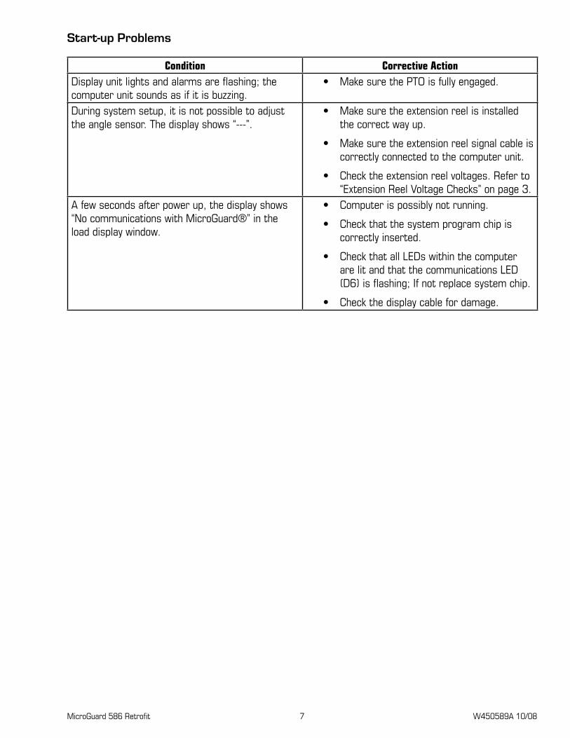
Start-up problems
Condition Corrective ActionDisplay unit lights and alarms are flashing; the computer unit sounds as if it is buzzing.
Make sure the PTO is fully engaged.•
During system setup, it is not possible to adjust the angle sensor. The display shows “---”.
Make sure the extension reel is installed •the correct way up.
Make sure the extension reel signal cable is •correctly connected to the computer unit.
Check the extension reel voltages. Refer to •“Extension Reel Voltage Checks” on page 3.
A few seconds after power up, the display shows “No communications with MicroGuard®” in the load display window.
Computer is possibly not running. •
Check that the system program chip is •correctly inserted.
Check that all LEDs within the computer •are lit and that the communications LED (D6) is flashing; If not replace system chip.
Check the display cable for damage.•

MicroGuard 586 Retrofit 8 W450589A 10/08
System Schematic
DISPLAY UNIT
COMPUTER UNIT
CABLE #1 CABLE #4
BOOM EXTENSION REEL
ATB(optional)
POWER& FKO
SWING SWITCHESOR SWING POT
(optional)
PORT 1PISTON SIDE
PORT 2RODSIDE

MicroGuard 586 Retrofit 9 W450589A 10/08
Terminal block positions and Functions
JP11
JP7
JP8
JP9
JP10
JP12
JP13JP
3JP
5JP
6
1 2
3 4
5 6
1 2
3 4
5 6
1 2
3 4
5 6
1 2
3 4
51 2
3 4
5
1 2
3 4
1 2
3 4
1 2
3
1 2
3
1 2
3 4
CABLE 1: Power and FKO ConnectionsColor Function Connection
Black System Ground JP3-1 (Battery -VE)Red System Power JP3-2 (Battery +VE)
JumperSystem Supply JP3-3 (Battery +VE)Power Feed to FKO Relays JP5-1 (FKO In)
Green FKO Output to Mach. Solenoids JP5-2 (FKO Out)Not Used JP5-3 (RLY3 NO)Not Used JP5-4 (RLY3 NC)
CABLE 2: Display ConnectionsColor Function Connection
White Communication A JP12-1 (Display Data A)Green Communication B JP12-2 (Display Data B)Blue Reset JP12-3 (Reset)Red/Yellow + Power JP12-4 (DSPLY 1 PWR)Black/Orange - Power JP12-5 (DSPLY 1 GND)
MicroGuard 586 Retrofit 10 W450589A 10/08
CABLE 2: Display ConnectionsColor Function Connection
Not Used JP12-6 (DSPLY 1 GND)
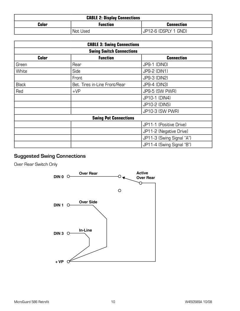
CABLE 3: Swing ConnectionsSwing Switch Connections
Color Function ConnectionGreen Rear JP9-1 (DIN0)White Side JP9-2 (DIN1)
Front JP9-3 (DIN2)Black Bet. Tires in-Line Front/Rear JP9-4 (DIN3)Red +VP JP9-5 (SW PWR)
JP10-1 (DIN4)JP10-2 (DIN5)JP10-3 (SW PWR)
Swing Pot ConnectionsJP11-1 (Positive Drive)JP11-2 (Negative Drive)JP11-3 (Swing Signal “A”)JP11-4 (Swing Signal “B”)
Suggested Swing Connections
Over Rear Switch Only
DIN 0
DIN 1
DIN 3
+ VP
ActiveOver Rear
Over Rear
Over Side
In-Line

MicroGuard 586 Retrofit 11 W450589A 10/08
Over Rear/Over Side Switch
DIN 0
DIN 1
DIN 3
+ VP
Over Rear
Over Side
In-Line
Over Rear/Side & In-Line/Houselock
DIN 0
DIN 1
DIN 3
+ VP
Over RearGreen
Over SideWhite
In-Line(Houseblock)
Black
Red
CABLE 4: Extension Reel ConnectionsColor Function Connection
Black ATB Switch Feed (2) JP8-1 (ATB FD)White Extension Sensor Signal JP8-2 (BM EXTN SIG)Green Angle Sensor Signal JP8-3 (BM ANG SIG)Brown ATB Switch Signal (1) JP8-4 (ATB SIG)Red + Sensor Drive JP8-5 (BM SNSR +DR)Blue - Sensor Drive JP8-6 (BM SNSR -DR)

MicroGuard 586 Retrofit 12 W450589A 10/08

COMMENTS?
SUGGESTIONS?
CORRECTIONS?
Send your feedback to:
Please include your name, company, and crane type.

Voice: 918-249-6125Fax: 918-459-2501
Greer Company is a part of Tulsa Winch Group.
www.team-twg.com
As a leader in product innovation, Greer Company is committed to the ongoing improvement of its equipment. We reserve the right to make changes to our products without notice.
© 2008 Tulsa Winch Group. All rights reserved. W450589A 10/08
For use with K450586