microfluidic free-surface flows: simulation and application j.e sprittles y.d. shikhmurzaev indian...
TRANSCRIPT
Microfluidic Free-Surface Flows: Simulation and ApplicationMicrofluidic Free-Surface Flows: Simulation and Application
J.E Sprittles
Y.D. Shikhmurzaev
Indian Institute of Technology, Mumbai
November 5th 2011
The University
Of Birmingham
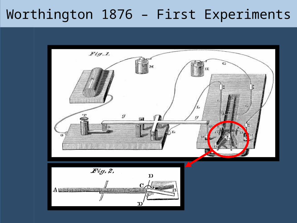
Worthington 1876 – First Experiments
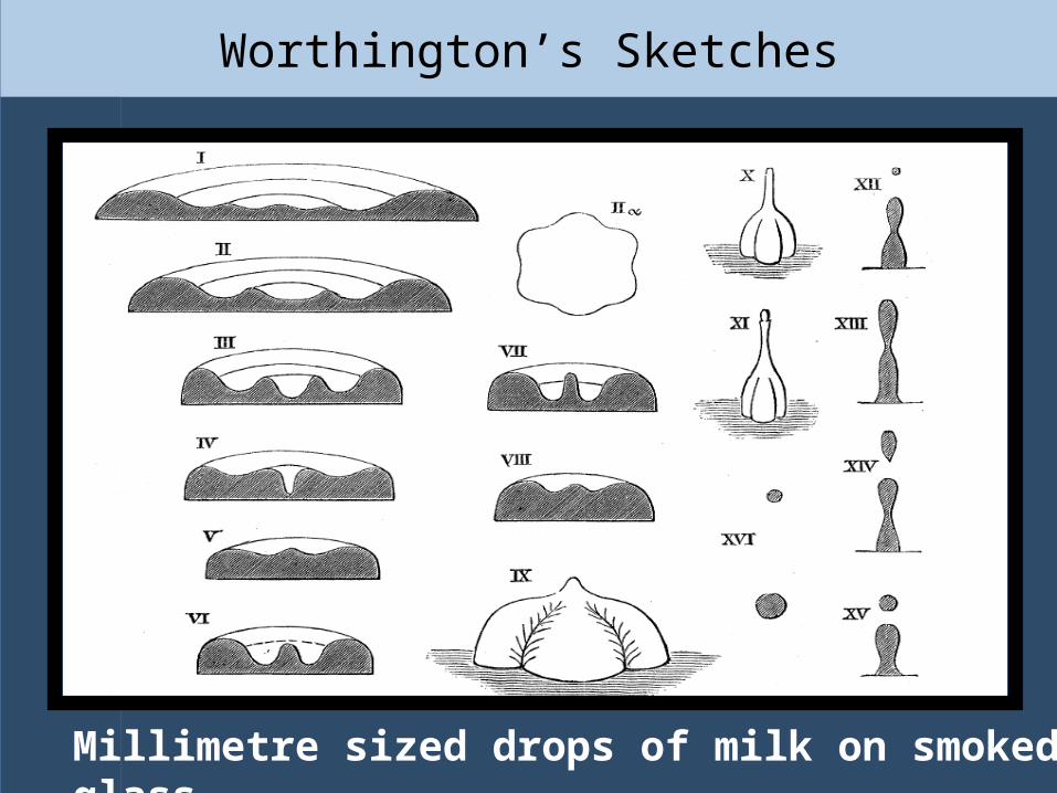
Worthington’s Sketches
Millimetre sized drops of milk on smoked glass.
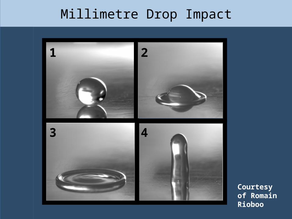
Millimetre Drop Impact
Courtesy of Romain Rioboo
1 2
3 4

Flow Control Using Chemically Patterned Solids
Hydrophobic
Hydrophilic
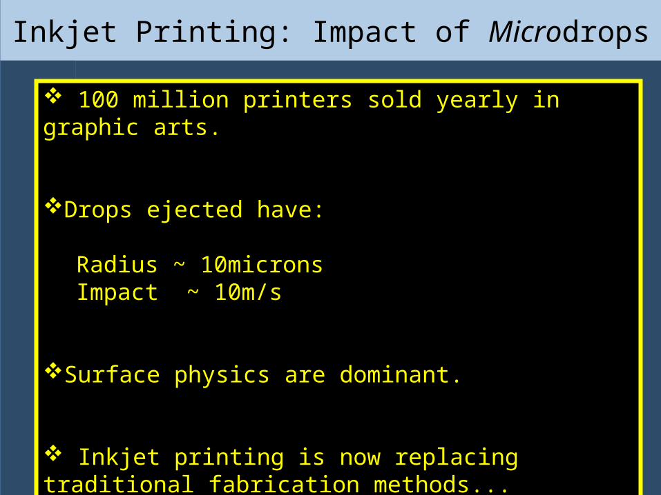
Inkjet Printing: Impact of Microdrops
100 million printers sold yearly in graphic arts.
Drops ejected have:
Radius ~ 10micronsImpact ~ 10m/s
Surface physics are dominant.
Inkjet printing is now replacing traditional fabrication methods...
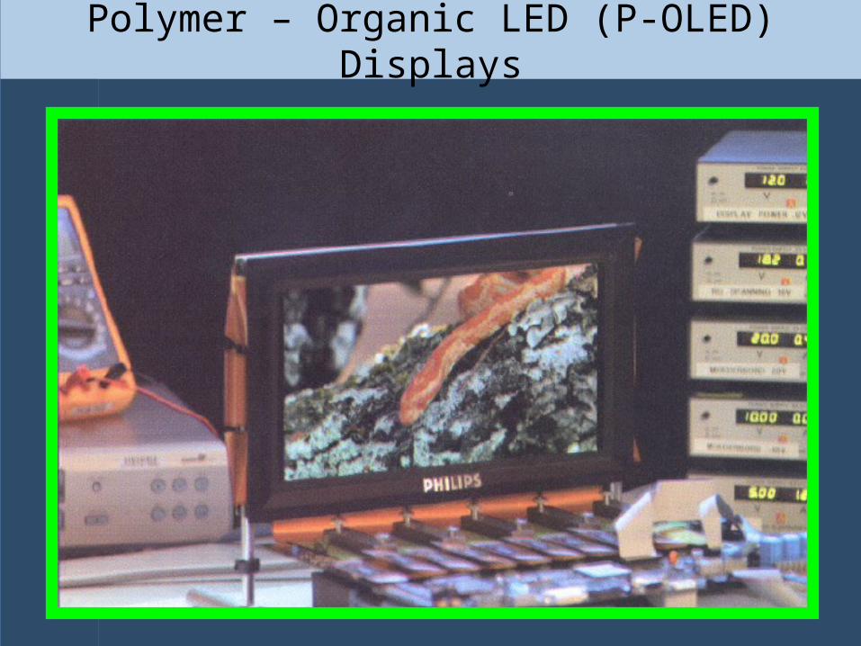
Polymer – Organic LED (P-OLED) Displays
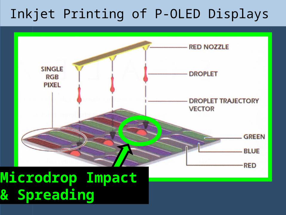
Inkjet Printing of P-OLED Displays
Microdrop Impact & Spreading
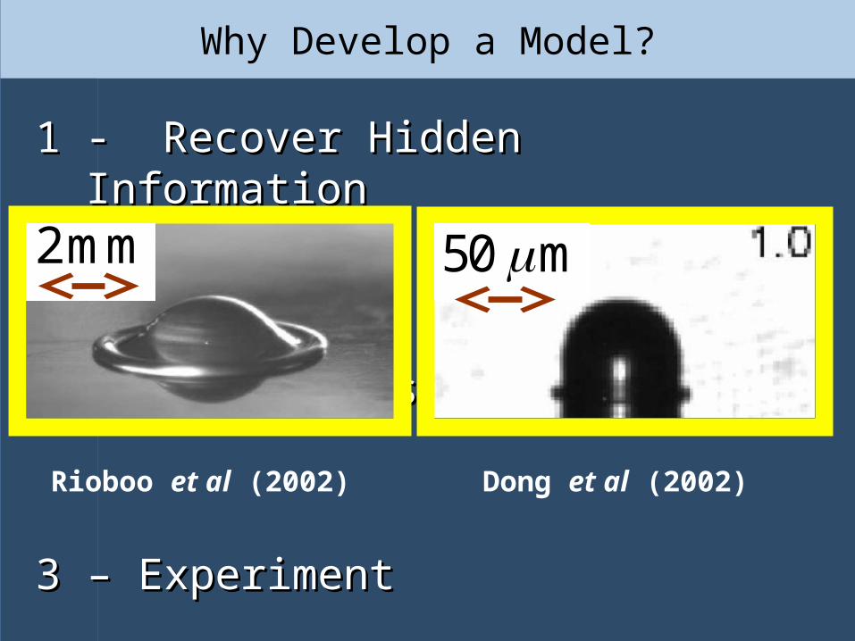
Why Develop a Model?
11 - Recover Hidden Information- Recover Hidden Information
22 - Map Regimes of Spreading - Map Regimes of Spreading
3 – Experiment3 – ExperimentRioboo et al (2002) Dong et al (2002)
2mm 50 m
Previous Modelling of Drop Spreading
Phenomena
Previous Modelling of Drop Spreading
Phenomena
r
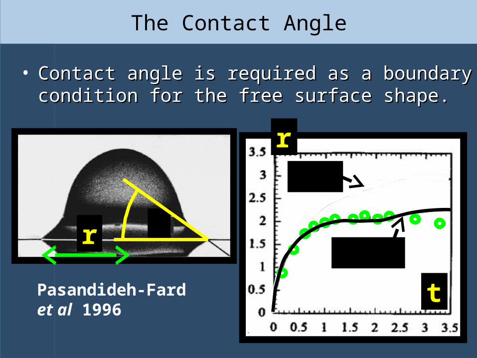
Pasandideh-Fard et al 1996
The Contact Angle
r
t
d( )d f t
d e
• Contact angle is required as a boundary condition Contact angle is required as a boundary condition for the free surface shape.for the free surface shape.
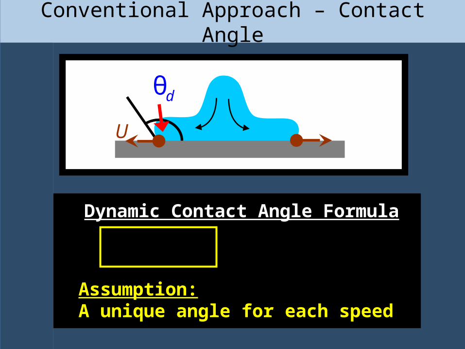
Conventional Approach – Contact Angle
1 3 2cose e e e
R
σ1
σ3 - σ2
Young Equation Young Equation Dynamic Contact Angle FormulaDynamic Contact Angle Formula
)
θd
U
Assumption:Assumption:A unique angle for each speedA unique angle for each speed
edθ = ( )f U

Is the Angle Always a Function of the Speed?(Experiments of Bayer & Megaridis 06)
1mm
60e
Water
10.18ms
10.25ms
)
U
d
-1(ms )U
d 30d d ( )f U
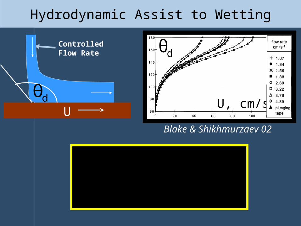
Hydrodynamic Assist to Wetting
Blake & Shikhmurzaev 02
U, cm/s
dθControlled Flow Rate
dθU
d ( )f U
Specific Physics of Wetting:
Interface Formation
Specific Physics of Wetting:
Interface Formation

The Simplest Model of Interface Formation (Shikhmurzaev 93)
uu 0, Re u u P + FSt
t
s1
1
1
1 1s1
1 1s11 1
11|| ||
v 0
n P n n
n P (I nn)=-
(u v ) n
( v )
5(v u )
4
s se
s sses
s
ff
t
t
* 12 || ||2
2 2s2
2 2s22 2
11
2|| || || 2 22
1,2 (0) 1,2
n [ u ( u) ] (I nn) (u U )
(u v ) n
( v )
v (u U ) , v U
s se
s sses
s s
s s
t
In the bulk:
On liquid-solid interfaces:
At contact lines:
On free surfaces:
Interface Formation Model
s s1 1 1 2 2 2
1 3 2
v e v e 0
cos
s s
d
/ 0U L
1
1 1 1 1 1||
u 0
n P n n
n P (I nn)=0
; ; v =u s s se e
ff
t
*|| ||
2 2 2 2
12|| || || 22
n [ u ( u) ] (I nn) (u U )
u U
; ;
v (u U ), v U
s se e
s s
e
Conventional Model
1,2 1,21,2 s1,2 1,2( v )
s sses
t
1,2 s
1,2 1,2 1,2 1,2( v )s
s s se
U
L t
U
Numerical Simulation of Drop Impact and
Spreading Phenomena
Numerical Simulation of Drop Impact and
Spreading Phenomena
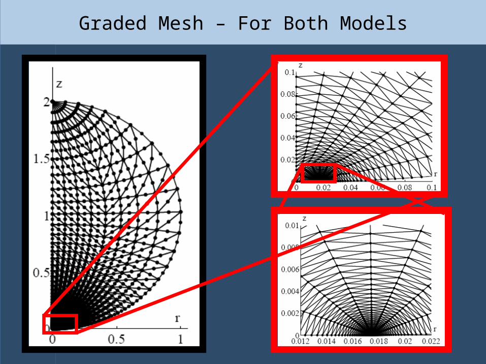
Graded Mesh – For Both Models
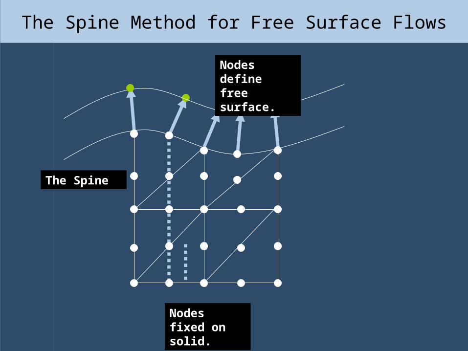
The Spine Method for Free Surface Flows
The Spine
Nodes fixed on solid.
Nodes define free surface.
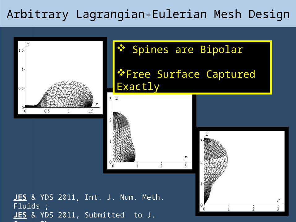
Arbitrary Lagrangian-Eulerian Mesh Design
JES & YDS 2011, Int. J. Num. Meth. Fluids ;JES & YDS 2011, Submitted to J. Comp. Phys.
Spines are Bipolar
Free Surface Captured Exactly
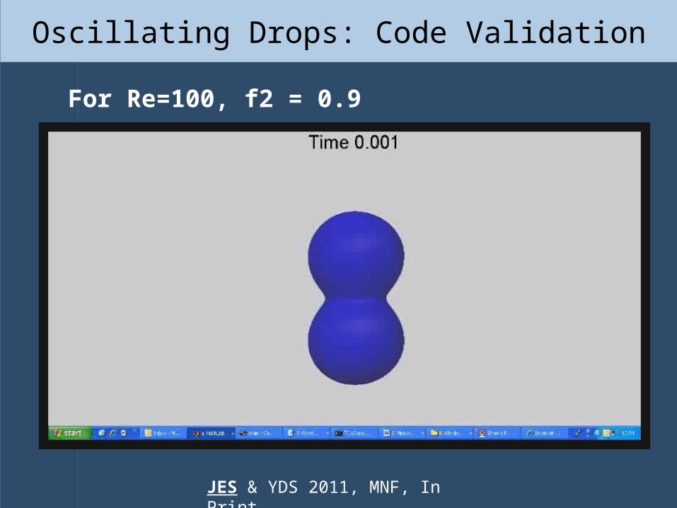
Oscillating Drops: Code Validation
For Re=100, f2 = 0.9
JES & YDS 2011, MNF, In Print
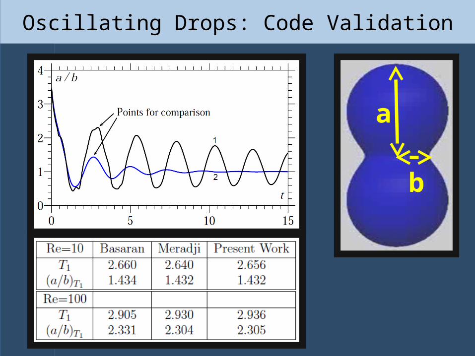
Oscillating Drops: Code Validation
a
b
Removal of Spurious Pressure
Removal of Spurious Pressure

Pressure Behaviour for Obtuse Angles
The pressure plot from a typical simulation.
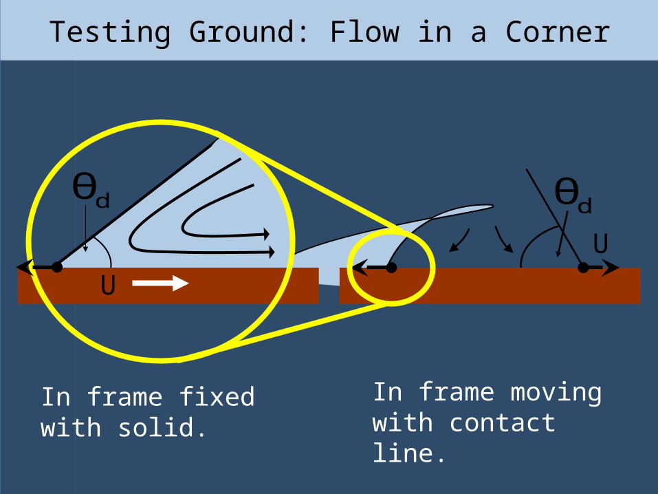
Testing Ground: Flow in a Corner
dθ
U
dθ
In frame moving with contact line.
In frame fixed with solid.
U
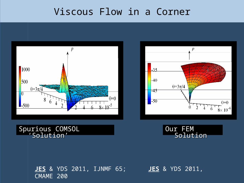
Viscous Flow in a Corner
Spurious COMSOL ‘Solution’Spurious COMSOL ‘Solution’
JES & YDS 2011, IJNMF 65; JES & YDS 2011, CMAME 200
Our FEM SolutionOur FEM Solution

Results Results
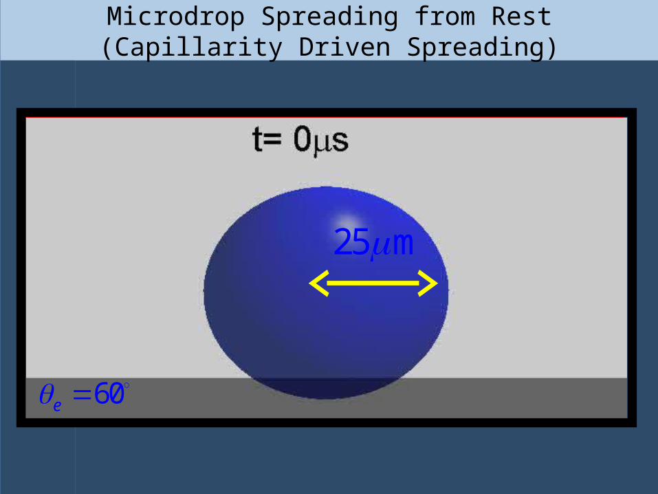
Microdrop Spreading from Rest(Capillarity Driven Spreading)
Apex
Velocity Scale
Pressure Scale
CapillaryWave
25 m
60e
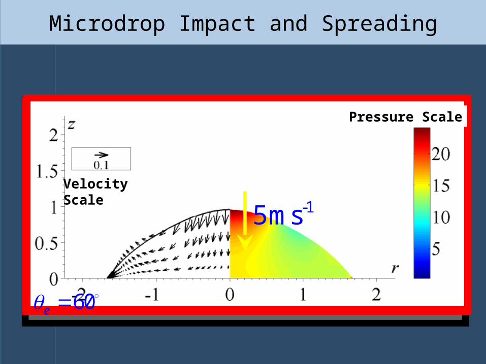
Microdrop Impact and Spreading
60e
Velocity Scale
Pressure Scale
-15ms

Speed – Angle Relationships:Comparison of IFM with Conventional Model.
0.702cos cos
tanh 4.96cos 1e d
e
U
0.01 100 1
Rest (IFM)
Impact (IFM)
-1(ms )U
Conventional Model.
d
Jiang et al 79
Increase in Contact Line Speed
Jump in Contact Line Speed
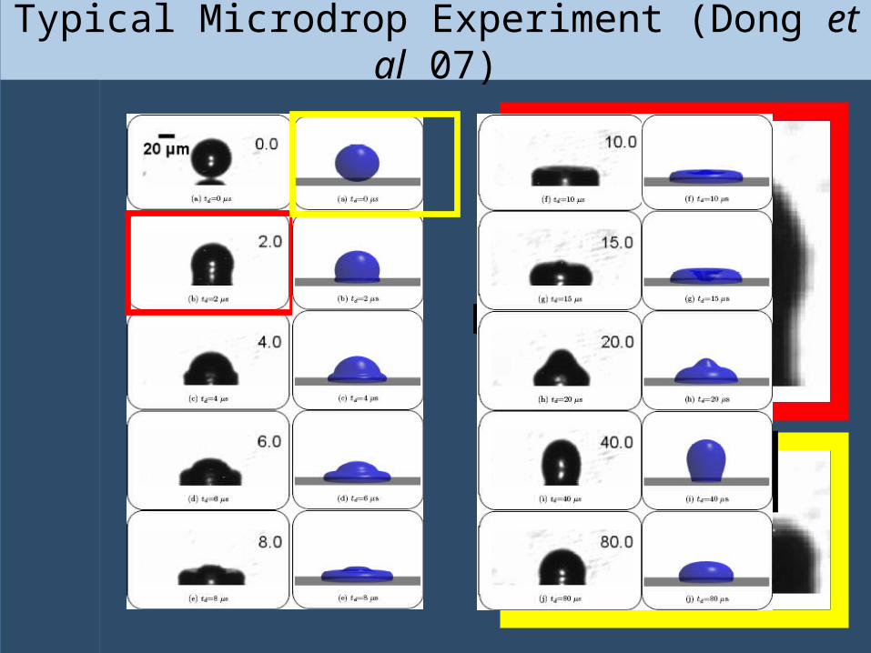
Typical Microdrop Experiment (Dong et al 07)
?
?
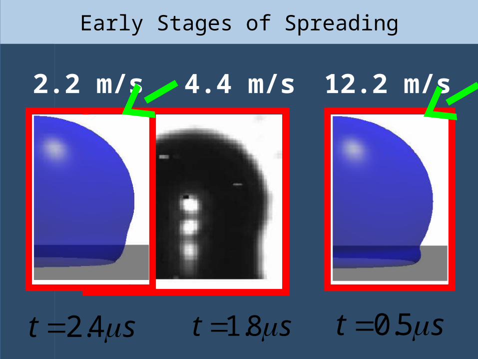
Early Stages of Spreading
0.5t s1.8t s2.4t s
2.2 m/s 4.4 m/s 12.2 m/s
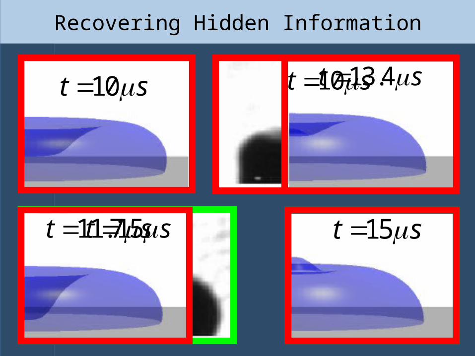
Recovering Hidden Information
15t s11.7t s
13.4t s10t s
15t s
10t s
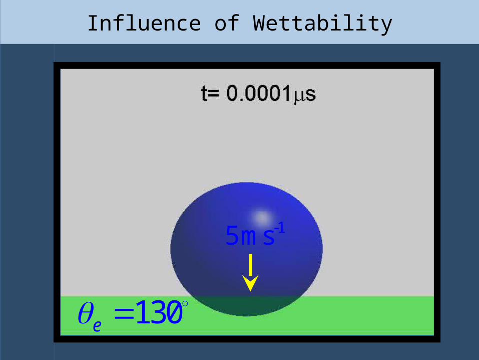
Influence of Wettability
130e
-15ms
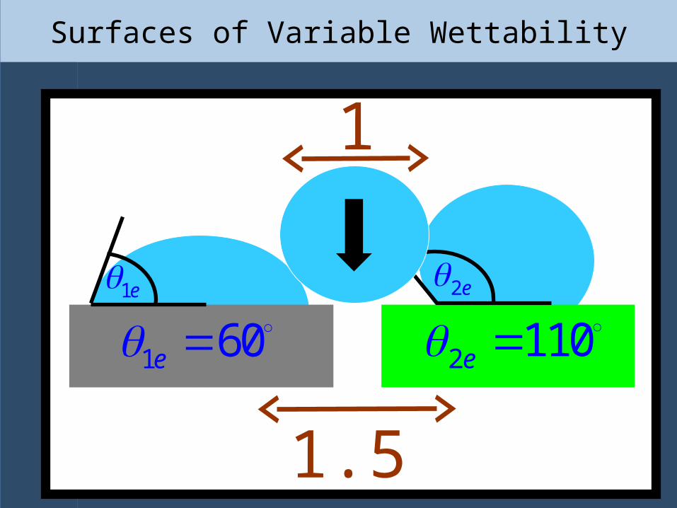
Surfaces of Variable Wettability
2e1e
1 60e 2 110e
1
1.5
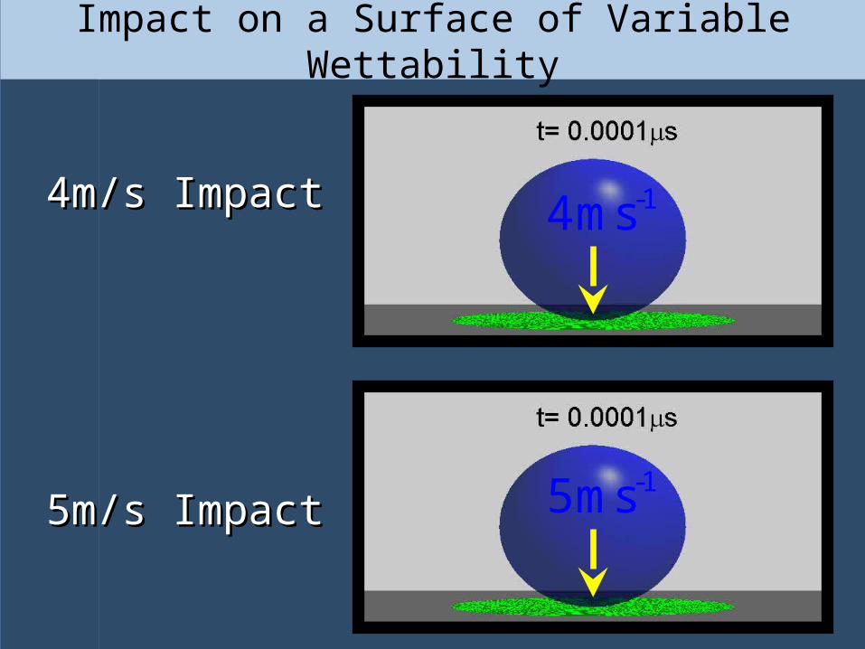
Impact on a Surface of Variable Wettability
4m/s Impact4m/s Impact
5m/s Impact5m/s Impact
-14ms
-15ms

Current/Future Work & Possible Avenues for
Collaboration
Current/Future Work & Possible Avenues for
Collaboration
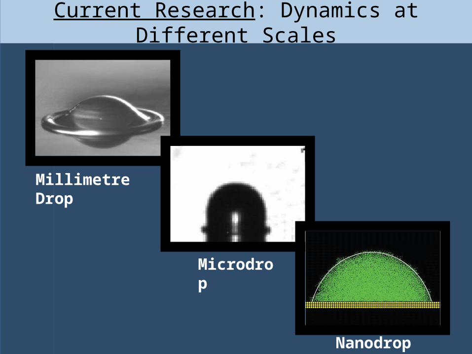
Current Research: Dynamics at Different Scales
Millimetre Drop
Microdrop
Nanodrop
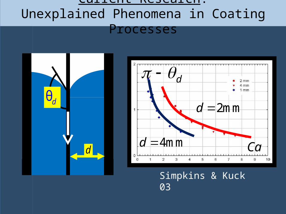
Current Research:Unexplained Phenomena in Coating Processes
Ca
d
2mmd
4mmd d
θd
Simpkins & Kuck 03

Current Research: Nanofluidics
“While inertial effects may also be important, the influence of the dynamic contact angle should not be ignored.” (Martic et al 02)
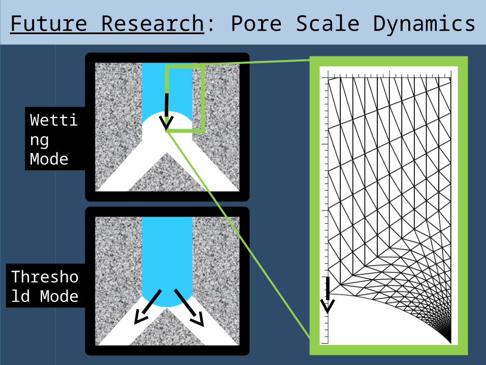
Future Research: Pore Scale Dynamics
Wetting Mode
Threshold Mode
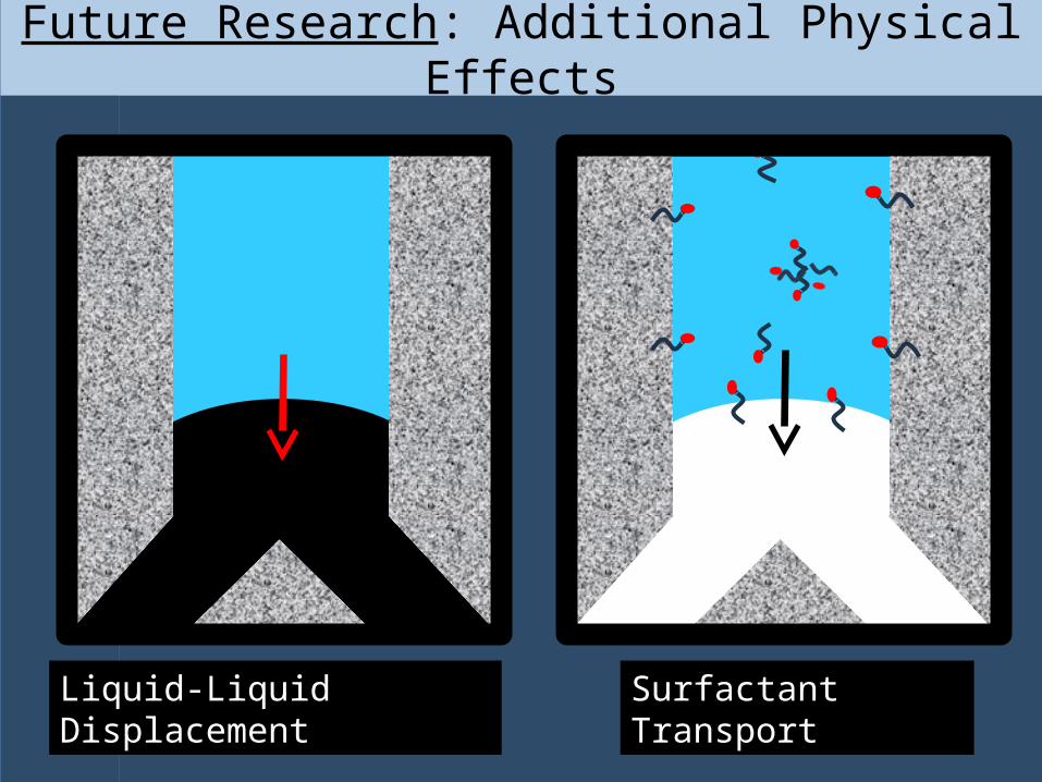
Future Research: Additional Physical Effects
Liquid-Liquid Displacement Surfactant Transport
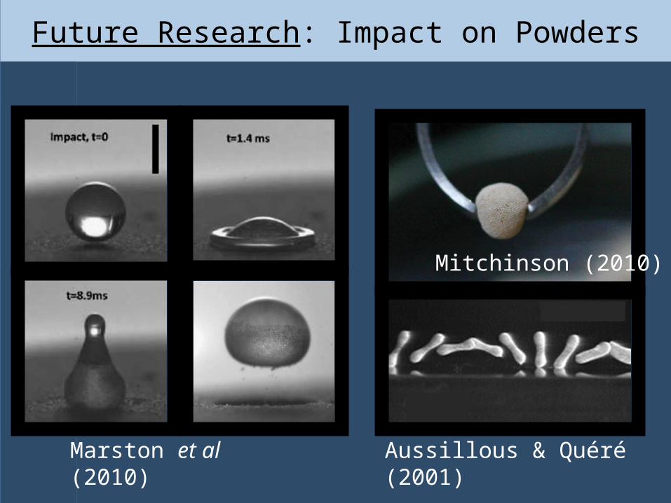
Future Research: Impact on Powders
Marston et al (2010) Aussillous & Quéré (2001)
Mitchinson (2010)
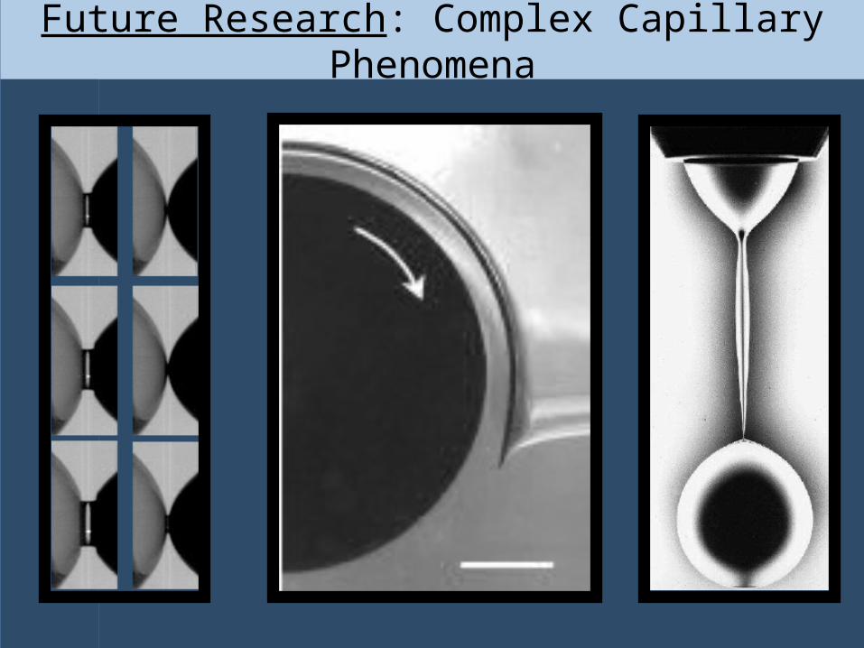
Future Research: Complex Capillary Phenomena
ThanksThanks

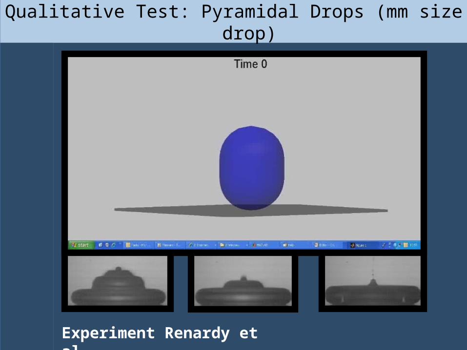
Qualitative Test: Pyramidal Drops (mm size drop)
Experiment Renardy et al.
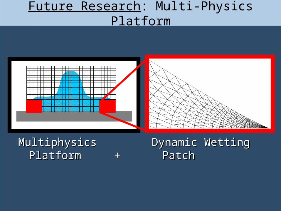
Future Research: Multi-Physics Platform
)
Multiphysics Platform + Multiphysics Platform + Dynamic Wetting PatchDynamic Wetting Patch
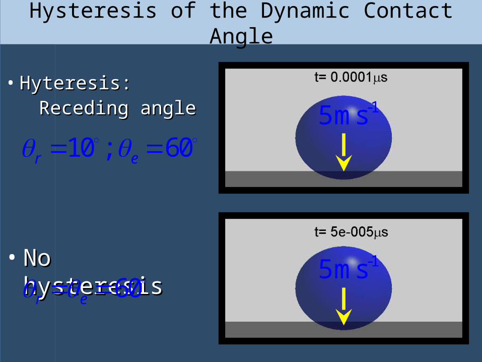
Hysteresis of the Dynamic Contact Angle
• Hyteresis:Hyteresis: Receding angleReceding angle
• No hysteresisNo hysteresis -15ms
-15ms
60r e
60e 10 ;r

Small DropsHigh Impact Speed
Analytic Progress: When Does ?
Stokes Region(viscous forces dominate inertial forces)
Length of interface formation process
d ( )f U
Slow Spreading of Large Drops

Comparison With Experiments
0.0001 0.0010 0.0100 0.1000 1.0000
0
30
60
90
120
150
180
d
Ca
0.0001 0.0010 0.0100 0.1000 1.0000
0
30
60
90
120
150
180
d
Ca
Perfect wetting (Hoffman 1975; Ström et al. 1990; Fermigier & Jenffer 1991)
Partial wetting (□: Hoffman 1975;
: Burley & Kennedy 1976; , ,: Ström et al. 1990)
The theory is in good agreement with all experimental The theory is in good agreement with all experimental data published in the literature.data published in the literature.
s/P. 10-103 , 67
0.0 0.1 0.2 0.3
60
90
120
150
180d
Ca
0.0 0.1 0.2 0.3 0.4 0.5
60
90
120
150
180
d
Ca
0.0 0.1 0.2 0.3 0.4
60
90
120
150
180
d
Ca
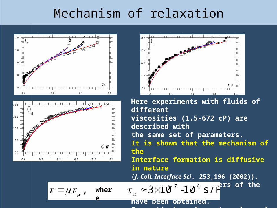
Here experiments with fluids of differentviscosities (1.5-672 cP) are described with the same set of parameters.It is shown that the mechanism of theInterface formation is diffusive in nature (J. Coll. Interface Sci. 253,196 (2002)). Estimates for parameters of the modelhave been obtained.In particular, for water-glycerol mixtures:
where
Mechanism of relaxation
Numerical Artifacts in the Computation of
Viscous Corner Flow
Numerical Artifacts in the Computation of
Viscous Corner Flow
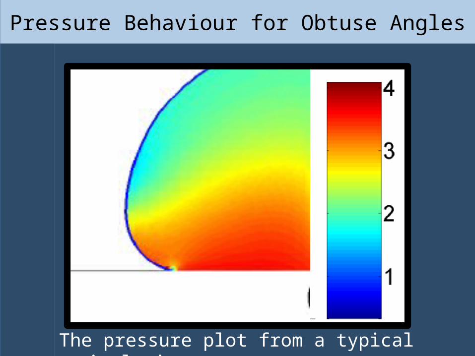
Pressure Behaviour for Obtuse Angles
The pressure plot from a typical simulation.

Testing Ground: Flow in a Corner
dθ
U
dθ
In frame moving with contact line.
In frame fixed with solid.
U
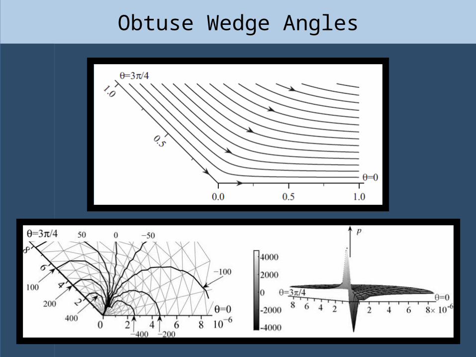
Obtuse Wedge Angles
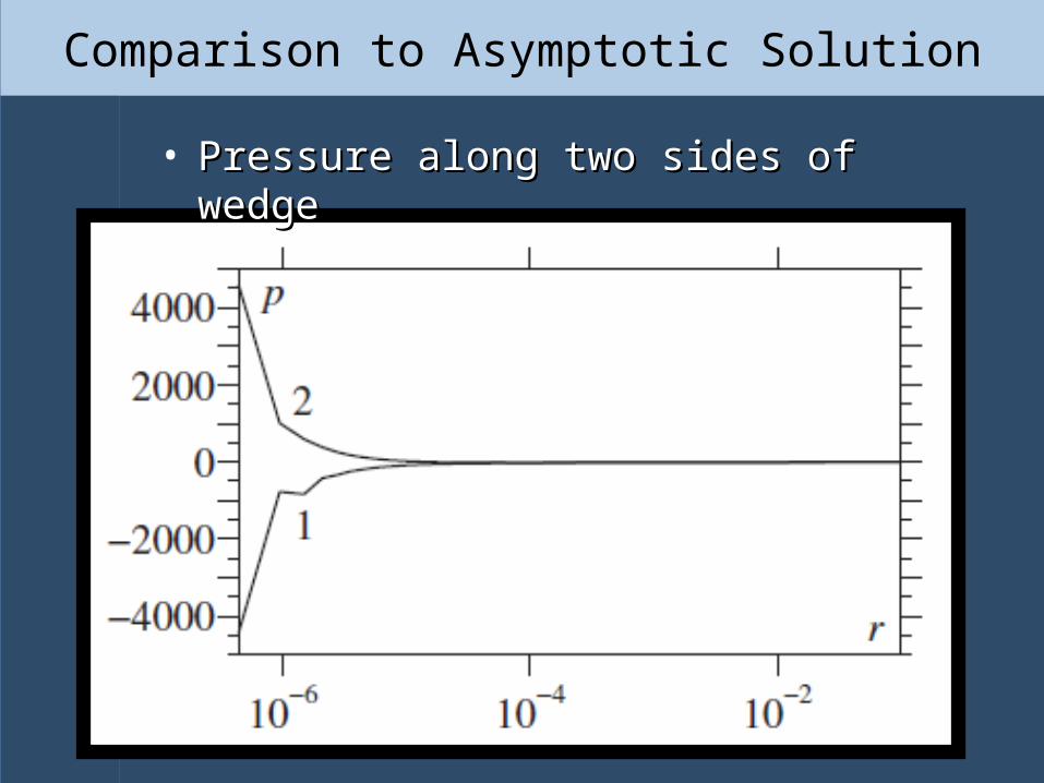
Comparison to Asymptotic Solution
• Pressure along two sides of wedgePressure along two sides of wedge
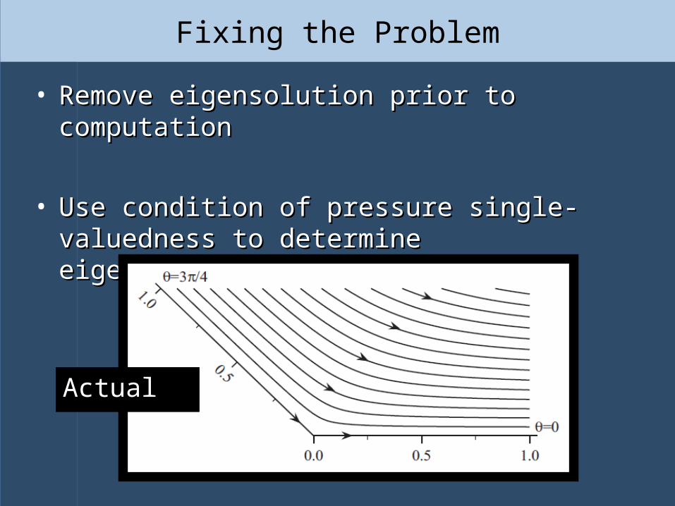
Fixing the Problem
• Remove eigensolution prior to computationRemove eigensolution prior to computation
• Use condition of pressure single-valuedness to Use condition of pressure single-valuedness to determine eigensolution’s contribution.determine eigensolution’s contribution.
ComputedComputedActualActual
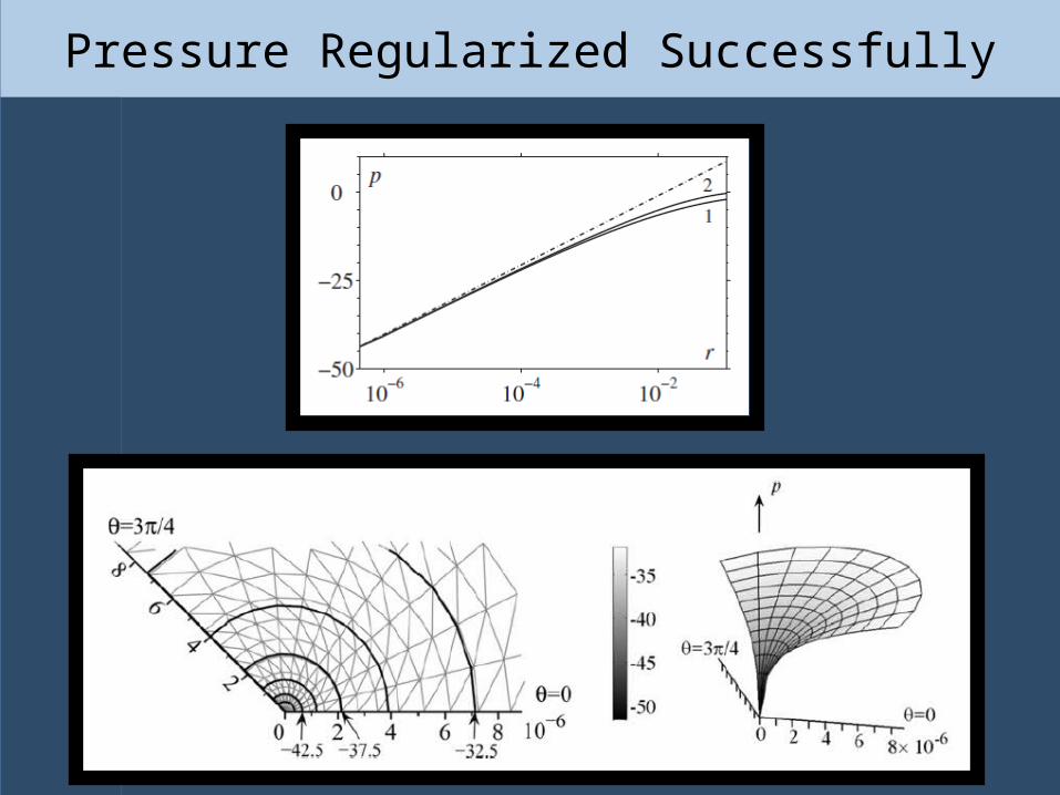
Pressure Regularized Successfully