microchannel heat exchangers based on alloy 230 – exposure ... · fwp 1022406 –advanced alloy...
TRANSCRIPT

Microchannel Heat Exchangers Based on Alloy 230 – Exposure
Characteristics and Mechanical Behavior
FWP 1022406 –Advanced Alloy Development Period of performance: 10/1/2016 – 9/30/2017
Ömer N. DoğanResearch & Innovation Center
National Energy Technology Laboratory1450 Queen Avenue, S.W., Albany, Oregon 97321
Month 31, 2016
Crosscutting Technology Research Project Review March 22, 2017 – Pittsburgh, PA
2
Acknowledgements
Monica KapoorKyle RozmanRichard OleksakSajedur Akanda
Casey CarneyJeffrey HawkGordon Holcomb
Rajesh SaranamPatrick McNeffBrian Paul
DISCLAIMER"This report was prepared as an account of work sponsored by an agency of the United States Government. Neither the United States Government nor any agency thereof, nor any of their employees, makes any warranty, express or implied, or assumes any legal liability or responsibility for the accuracy, completeness, or usefulness of any information, apparatus, product, or process disclosed, or represents that its use would not infringe privately owned rights. Reference herein to any specific commercial product, process, or service by trade name, trademark, manufacturer, or otherwise does not necessarily constitute or imply its endorsement, recommendation, or favoring by the United States Government or any agency thereof. The views and opinions of authors expressed herein do not necessarily state or reflect those of the United States Government or any agency thereof."
This work was performed in support of the U.S. Department of Energy’s Fossil Energy (FE) Crosscutting Technology Research and Advanced Turbines Programs. The research was executed through NETL’s Research and Innovation Center’s Advanced Alloy Development Field Work Proposal.

3
• Accelerating commercialization of supercritical carbon dioxide power cycle technology by addressing materials and manufacturing challenges for components of sCO2 power systems.
• Joining of similar and dissimilar power plant alloys• Performance of joints in sCO2 power cycle environments
• Milestones• Demonstrate mechanical and environmental performance of joints in supercritical CO2 ‐ 09/30/2017
• Deliverables• Technical report (either presentation or publication) on the high temperature corrosion of the joined power plant materials. ‐ 09/30/2017
• Technical report (either presentation or publication) on the cross‐joint strength of typical power plant materials. ‐ 09/30/2017
Project Goals and Objectives

4
• Supercritical CO2 power cycles and compact heat exchangers• Materials issues in manufacturing compact heat exchangers
• Diffusion bonding (DB)• Transient liquid phase bonding (TLPB)
• Mechanical strength of bonded structures• High‐temperature corrosion of bonds in sCO2
Outline

5
Supercritical CO2 Power Cycles
Indirect sCO2 Cycle
MainCompressor
RecycleCompressor
sCO2Turbine
Heater
Primary Heat Exchanger
High Temperature Recuperator
Low Temperature Recuperator
Direct sCO2 Cycle
Primary Heat Exchanger
sCO2TurbinePressurized
Oxy‐combustion Generator
Essentially pure CO2
CO2 with combustion products including O2, H2O and SO2

6
Compact Heat Exchangers for sCO2 Cycles

7
Micro channel heat exchangers
Heat Exchangers
Microfluidics.com, Basuki et al., MSEA, 538 (2012) 340‐348; Zapirain et al. Physics Procedia, 12 (2011) 105‐112
• Pattern microscale flow paths• Join these using laser welding,
diffusion bonding or brazing
• Dimensional Tolerances‐ Pressure & Temperature Drop
• Uniform microstructure ‐ Environmental Resistance
• Higher heat transfer efficiency due to shorter heat diffusion lengths• Smaller size • Modular Design
Bond
Diffusion bonding, brazing, and transient‐liquid‐phase (TLP) bonding are the most robust approaches for sCO2 cycles

8
Schematic of diffusion bonding process
Parallel, elliptical voids, contact between ridge tops
550 µm shims
Area Bonded
Pressure & Temperature
• Solid state process• Applied high pressure at high
temperature• Void closure due to diffusion of
constituent atoms and creep processes by application of high pressure
H230 @ 1150°C
Balance creep, time, pressure and bonded area
Are
a B
onde
d
Bond Pressure (MPa)
A. Hill, E. Wallach. Modeling solid‐state diffusion bonding, Acta Metallurgica 37 (1989) 2425‐2437.

9
Transient-Liquid-Phase Bonding
10 µm
Ni‐P plating acts as a low‐melting interlayer
Bonding Temperature
H230
Ni‐PP
Solid
ificatio
n• Both solid state and
liquid state reactions
• Less pressure than diffusion bonding
• Lower melting point interlayer
• Isothermal melting and solidification of interlayer

10
Output of Bonding - stacks
Cold rolled and 1232 °C solution annealed ‐ 550 µm H230 shims
Stacks
Stacked onto a fixture Pressed at 1150°C, 12.7MPa in vac
Tensile Samples
• Downselect between H230 & H282
• H230 – NiCrW solid solution strengthend alloy
• H282 – Gamma prime strengthened alloy
• H230 was selected and challenges with H282 will be discussed later

11
Microstructure
200 µm
Sheet Sheet
100 µm
Grain growth
Etched microstructure to observe grain growth through the bond line
Diffusion Bonding of Alloy H230
Mechanical Behavior
W, C
0.0
0.1
0.2
0.3
0.4
0.5
Yield Strength (GPa) Elongation
DiffusionBondedBase Alloy230
RT
Ductile fracture along the precipitate bands.

12
TLP Bonding of Alloy H230
100 nm50 µm
Grain growth across the bond
100 µm
Bondline
Isothe
rmally
Solid
ified
Zon
e Primary CarbidesTLP Bond
Sheet
Sheet
No nanoscale phase near the bondline
Base Alloy
Bondline
18
19
20
21
22
23
24
0 50 100 150 200 250 300
Cr
Distance from the bondline (µm)
Compo
sitio
n (W
t. %)
H230ISZ
0.00
0.10
0.20
0.30
0 50 100 150 200 250 300
P
Distance from the bondline (µm)
Compo
sitio
n (W
t. %) H230ISZ
• Cr important for oxidation resistance ‐Slight reduction in Cr near the bondline
• P should be as low as possible to avoid formation of brittle phases ‐ P is ~0.2 wt. % near the bondline
M. Kapoor, Mat. & Met. Trans. A, 2017

13
Tensile Testing Yield strength of TLP stacks is ~86% of bulk H230
Tensile samples from H230 stacks
Plastic strain is constrained in the ISZ
1 mm10 µm100 µm
Fracture Surface
Ductile fracture through the ISZ
750°C

14
High temperature mechanical propertiesLow cycle fatigue properties @ 760°C
TLPB H230
Cycles to Failure
Bulk H230 760°C
0.01
0.1
1
10 100 1000 10000 100000
Total Strain Ra
nge (%
)
Cycles to Failure
Creep properties

15
Challenges in bonding of H282
Challenges with TLP bonding of H282 – Surface oxides & Intermetallic Formation
20 um
Al2O3 particles (dark) on the fracture surface
Fracture Surface
50 um
Intermetallic formation
EDS maps in the vicinity of the bondline
P Ti Mo
Al2O3 particles (dark) along the bondline
Bondline after TLP bonding
20 µm
Al
O
50 µmH282
Ni‐12P coating on the metal for TLP bonding
Coating does not adhere to the metal

16
Shrinkage Pores in TLP Bonding
1 µm
Bond line
50 µm
Pores in the vicinity of the bondlinewith a lamellar structure.
H230
Ni‐PP
Solid
ificatio
n

17
High-Temperature Oxidation of Bonded Regions in CO2
• Gas: 1 bar CO2 (99.999% purity) • O2 level in furnace tube: <12 ppm• Gas flow rate: 0.032 kg/h• Temperature: 700°C• Duration: 4000 h in 500 h increments• 24 h purging with CO2 before heating
CharacterizationMass Change
XRDSEM
1 bar CO2 Exposures250 bar CO2 Exposure
• Gas: CO2 (99.999% purity)• Flow rate: 2 ml/min• Temperature: 720°C• Duration: 1500 h in 500 h incr.• Argon purging before heating
18
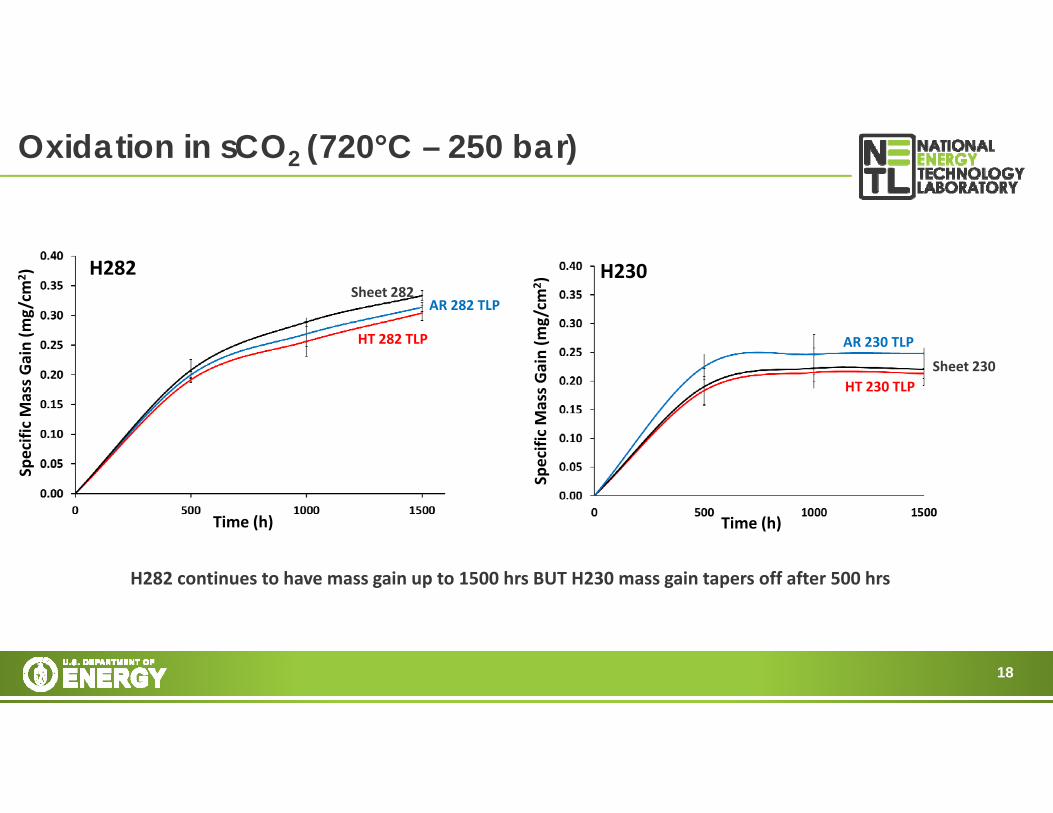
Oxidation in sCO2 (720°C – 250 bar)
Sheet 282
HT 282 TLP
AR 282 TLP
Specific Mass Gain (m
g/cm
2 )
Time (h)
H282
Specific Mass Gain (m
g/cm
2 )Time (h)
Sheet 230HT 230 TLP
AR 230 TLP
H230
H282 continues to have mass gain up to 1500 hrs BUT H230 mass gain tapers off after 500 hrs
19
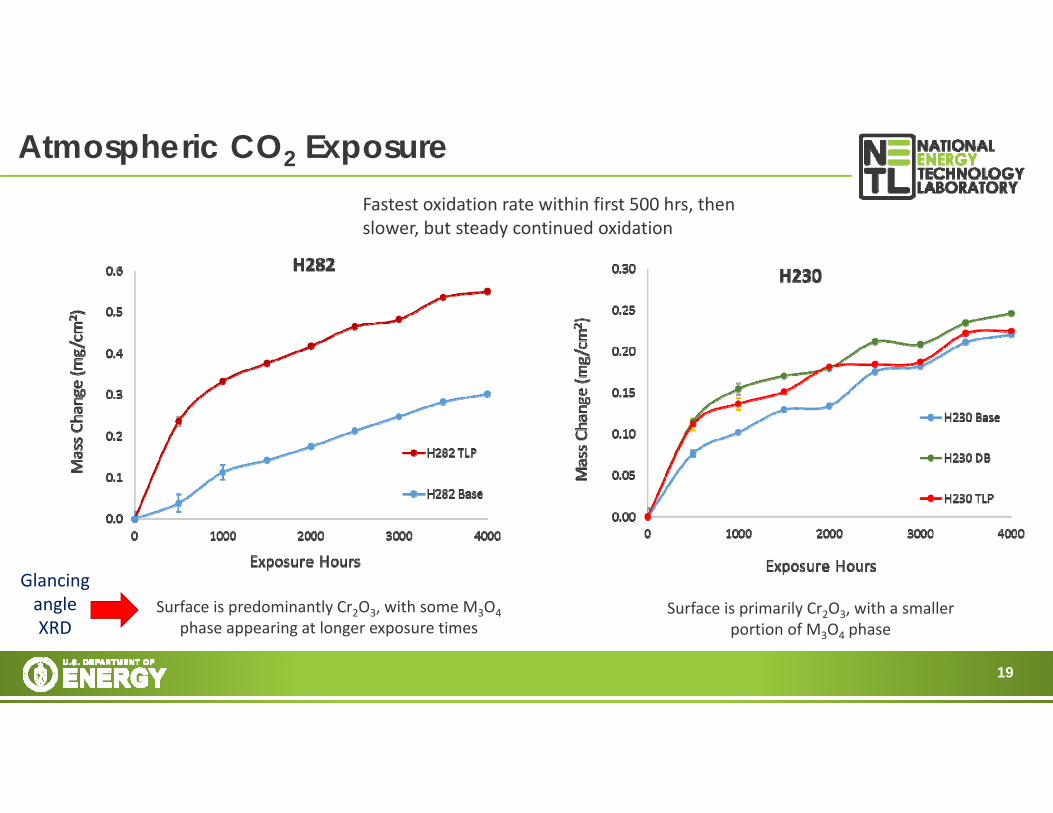
Atmospheric CO2 ExposureFastest oxidation rate within first 500 hrs, then slower, but steady continued oxidation
Surface is predominantly Cr2O3, with some M3O4phase appearing at longer exposure times
Surface is primarily Cr2O3, with a smaller portion of M3O4 phase
Glancing angle XRD

20
Bonded alloys exposed to 700 °C aCO2
500 h exposure time 1500 h exposure time
• Thin, protective Cr-rich oxide layers are formed for H230 and H282 during exposure to 700 °C aCO2.• Internal oxidation of Al leads to a sub-surface layer depleted of γ’ phase in H282.• No difference in oxidation resistance is observed near/far from the bond layer for either alloy.

21
Bonded alloys exposed to 720 °C sCO2
500 h exposure timeSimilar results as H230 and H282 bonded samples exposed to 700 °C aCO2:
• Thin Cr-rich oxide layers.
• Internal oxidation of Al leads to a sub-surface layer depleted of γ’ phase in H282.
• No difference in oxidation resistance observed near/far from the bond layer.
One difference is that sCO2 exposures show a 2-layer oxide structure containing some Mn(H230) or Ti (H282) in addition to Cr. This is the subject of ongoing investigation.
22
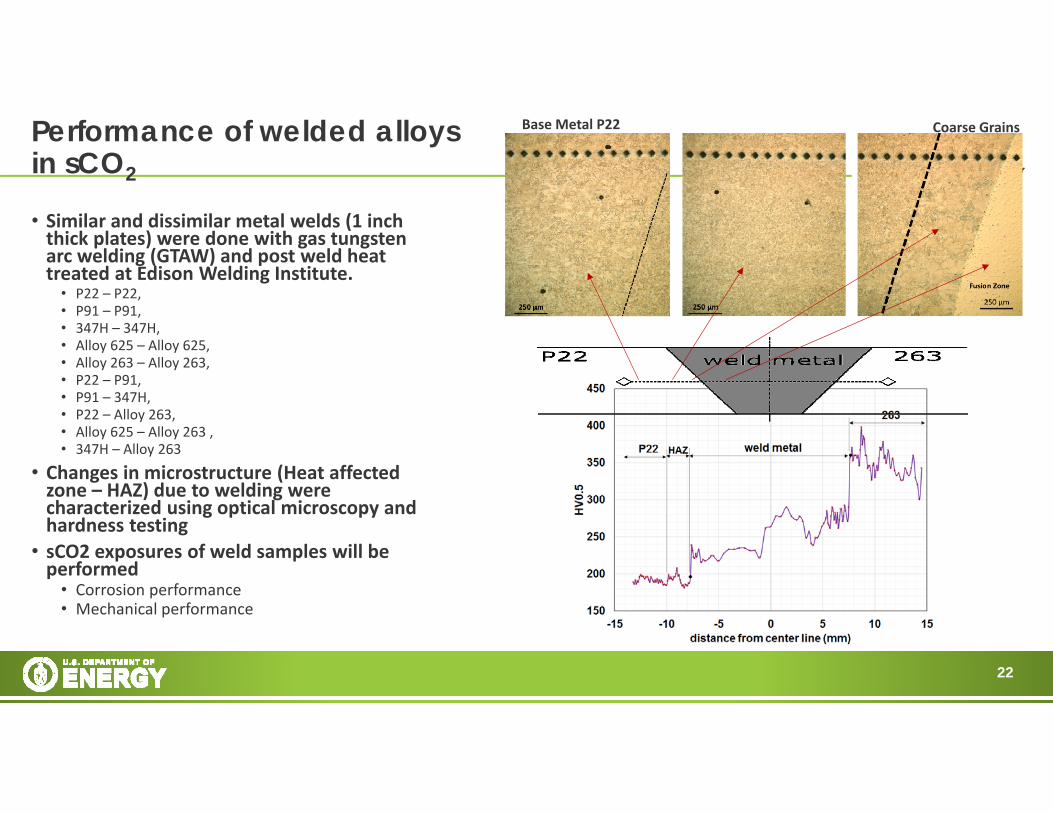
• Similar and dissimilar metal welds (1 inch thick plates) were done with gas tungsten arc welding (GTAW) and post weld heat treated at Edison Welding Institute.
• P22 – P22, • P91 – P91, • 347H – 347H, • Alloy 625 – Alloy 625, • Alloy 263 – Alloy 263, • P22 – P91, • P91 – 347H, • P22 – Alloy 263, • Alloy 625 – Alloy 263 , • 347H – Alloy 263
• Changes in microstructure (Heat affected zone – HAZ) due to welding were characterized using optical microscopy and hardness testing
• sCO2 exposures of weld samples will be performed
• Corrosion performance• Mechanical performance
Performance of welded alloys in sCO2
Coarse Grains Base Metal P22
23
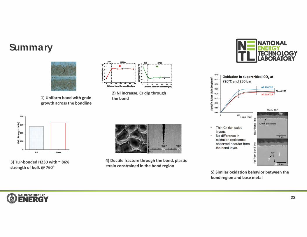
Summary
1) Uniform bond with grain growth across the bondline
2) Ni increase, Cr dip through the bond
3) TLP‐bonded H230 with ~ 86% strength of bulk @ 760°
4) Ductile fracture through the bond, plastic strain constrained in the bond region
5) Similar oxidation behavior between the bond region and base metal