micro motion technical overview and specification summary · 2019-06-17 · micro motion products...
TRANSCRIPT
Product Data SheetPS-00232, Rev X
June 2019
Micro Motion® Technical Overview andSpecification Summary
Micro Motion productsEmerson’s world-leading Micro Motion Coriolis flow and density measurement devices have set the standard for superiormeasurement technology. Micro Motion offers the best measurement solutions for any process challenge.
Micro Motion advantages
Technology leadership
Micro Motion is committed to technology innovations that deliver the highest-performing solutions for your complexmeasurement challenges.
Widest breadth of products
Micro Motion has the widest range of flow and density measurement devices for virtually any process, application, or fluid. A widevariety of wetted materials, line sizes, and an extensive range of output options enable optimal system integration.
Unparalleled value
Benefit from expert field and technical application service and support made possible from more than one million meters installedworldwide and over 40 years of flow and density measurement experience.
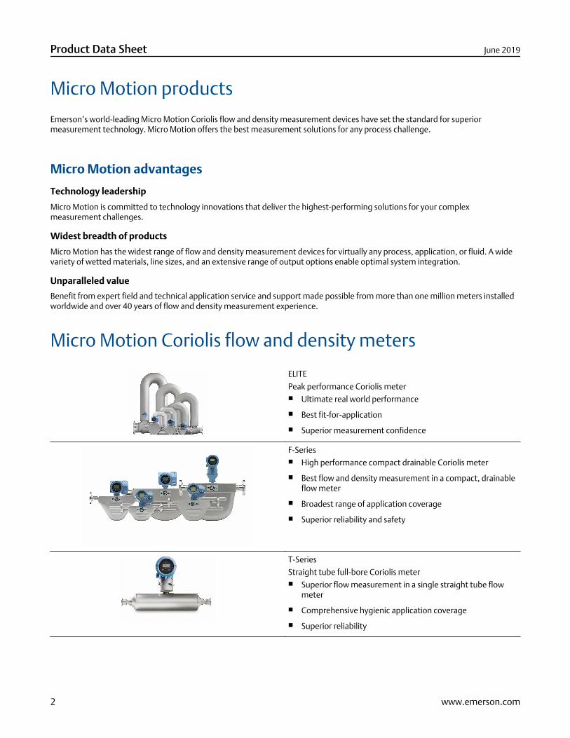
Micro Motion Coriolis flow and density meters
ELITE
Peak performance Coriolis meter■ Ultimate real world performance
■ Best fit-for-application
■ Superior measurement confidence
F-Series■ High performance compact drainable Coriolis meter
■ Best flow and density measurement in a compact, drainableflow meter
■ Broadest range of application coverage
■ Superior reliability and safety
T-Series
Straight tube full-bore Coriolis meter■ Superior flow measurement in a single straight tube flow
meter
■ Comprehensive hygienic application coverage
■ Superior reliability
Product Data Sheet June 2019
2 www.emerson.com
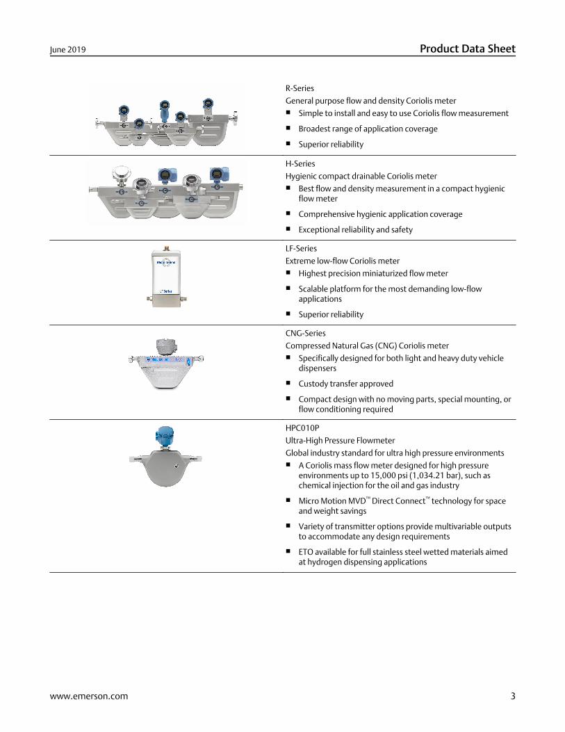
R-Series
General purpose flow and density Coriolis meter■ Simple to install and easy to use Coriolis flow measurement
■ Broadest range of application coverage
■ Superior reliability
H-Series
Hygienic compact drainable Coriolis meter■ Best flow and density measurement in a compact hygienic
flow meter
■ Comprehensive hygienic application coverage
■ Exceptional reliability and safety
LF-Series
Extreme low-flow Coriolis meter■ Highest precision miniaturized flow meter
■ Scalable platform for the most demanding low-flowapplications
■ Superior reliability
CNG-Series
Compressed Natural Gas (CNG) Coriolis meter■ Specifically designed for both light and heavy duty vehicle
dispensers
■ Custody transfer approved
■ Compact design with no moving parts, special mounting, orflow conditioning required
HPC010P
Ultra-High Pressure Flowmeter
Global industry standard for ultra high pressure environments■ A Coriolis mass flow meter designed for high pressure
environments up to 15,000 psi (1,034.21 bar), such aschemical injection for the oil and gas industry
■ Micro Motion MVD™ Direct Connect™ technology for spaceand weight savings
■ Variety of transmitter options provide multivariable outputsto accommodate any design requirements
■ ETO available for full stainless steel wetted materials aimedat hydrogen dispensing applications
June 2019 Product Data Sheet
www.emerson.com 3
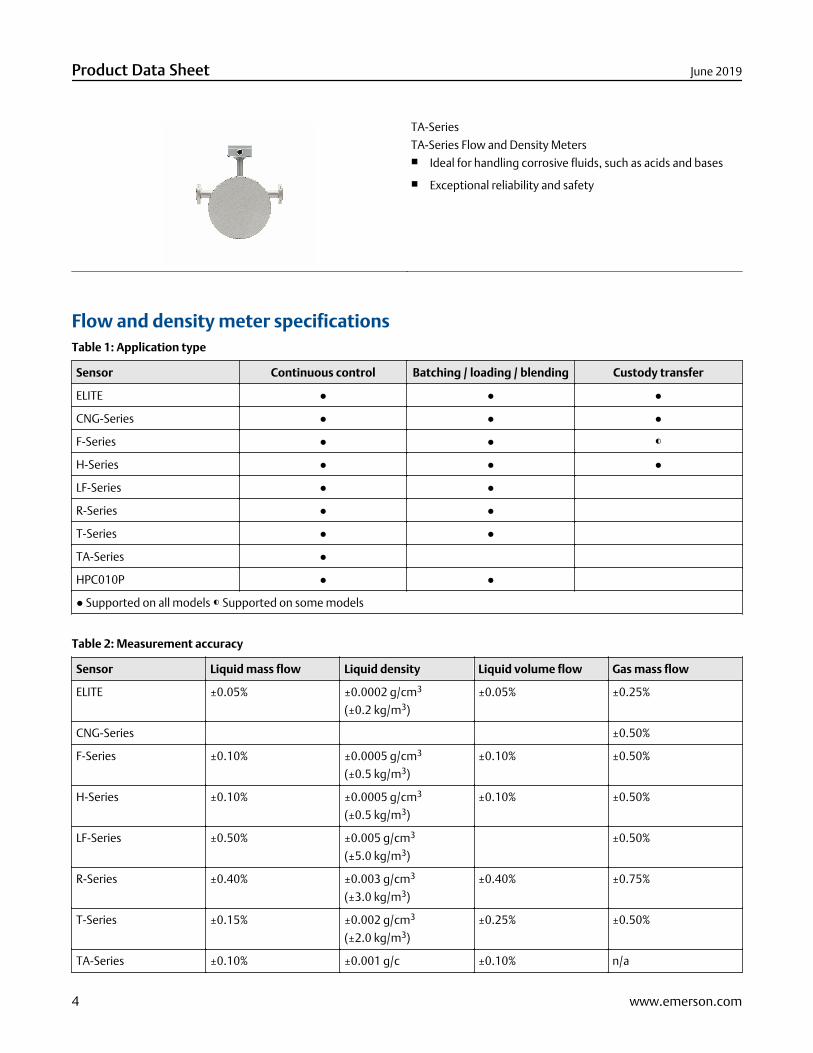
TA-Series
TA-Series Flow and Density Meters■ Ideal for handling corrosive fluids, such as acids and bases
■ Exceptional reliability and safety
Flow and density meter specificationsTable 1: Application type
Sensor Continuous control Batching / loading / blending Custody transfer
ELITE ● ● ●
CNG-Series ● ● ●
F-Series ● ● ◐
H-Series ● ● ●
LF-Series ● ●
R-Series ● ●
T-Series ● ●
TA-Series ●
HPC010P ● ●
● Supported on all models ◐ Supported on some models
Table 2: Measurement accuracy
Sensor Liquid mass flow Liquid density Liquid volume flow Gas mass flow
ELITE ±0.05% ±0.0002 g/cm3
(±0.2 kg/m3)
±0.05% ±0.25%
CNG-Series ±0.50%
F-Series ±0.10% ±0.0005 g/cm3
(±0.5 kg/m3)
±0.10% ±0.50%
H-Series ±0.10% ±0.0005 g/cm3
(±0.5 kg/m3)
±0.10% ±0.50%
LF-Series ±0.50% ±0.005 g/cm3
(±5.0 kg/m3)
±0.50%
R-Series ±0.40% ±0.003 g/cm3
(±3.0 kg/m3)
±0.40% ±0.75%
T-Series ±0.15% ±0.002 g/cm3
(±2.0 kg/m3)
±0.25% ±0.50%
TA-Series ±0.10% ±0.001 g/c ±0.10% n/a
Product Data Sheet June 2019
4 www.emerson.com
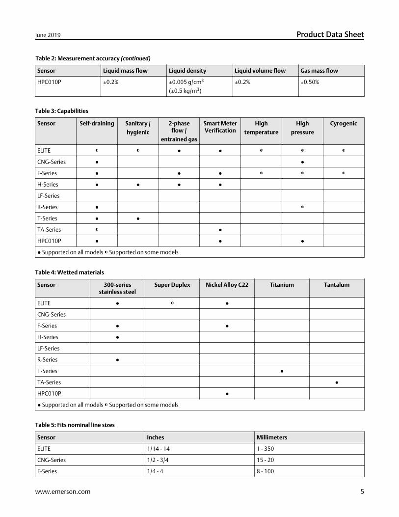
Table 2: Measurement accuracy (continued)
Sensor Liquid mass flow Liquid density Liquid volume flow Gas mass flow
HPC010P ±0.2% ±0.005 g/cm3
(±0.5 kg/m3)
±0.2% ±0.50%
Table 3: Capabilities
Sensor Self-draining Sanitary /
hygienic
2-phaseflow /
entrained gas
Smart MeterVerification
High
temperature
High
pressure
Cyrogenic
ELITE ◐ ◐ ● ● ◐ ◐ ◐
CNG-Series ● ●
F-Series ● ● ● ◐ ◐ ◐
H-Series ● ● ● ●
LF-Series
R-Series ● ◐
T-Series ● ●
TA-Series ◐ ●
HPC010P ● ● ●
● Supported on all models ◐ Supported on some models
Table 4: Wetted materials
Sensor 300-seriesstainless steel
Super Duplex Nickel Alloy C22 Titanium Tantalum
ELITE ● ◐ ●
CNG-Series
F-Series ● ●
H-Series ●
LF-Series
R-Series ●
T-Series ●
TA-Series ●
HPC010P ●
● Supported on all models ◐ Supported on some models
Table 5: Fits nominal line sizes
Sensor Inches Millimeters
ELITE 1/14 - 14 1 - 350
CNG-Series 1/2 - 3/4 15 - 20
F-Series 1/4 - 4 8 - 100
June 2019 Product Data Sheet
www.emerson.com 5

Table 5: Fits nominal line sizes (continued)
Sensor Inches Millimeters
H-Series 1/4 - 3 8 - 80
LF-Series 1/32 - 1/4 0.8 - 8
R-Series 1/4 - 4 8 - 50
T-Series 1/4 - 2 8 - 50
TA-Series 1/4 - 2 8 - 50
HPC010P 1/10 - 3/4 3 - 20
Micro Motion transmitters and controllers
5700
Advanced field-mount transmitter■ Integral and remote mount options
■ Wide variety of I/O and application capabilities to fit yourneeds
■ Large graphical display
■ Real time data logging and storage
4200
2-wire transmitter■ Integral and remote mount options
■ Compact, integral 2-wire transmitter design saves electricalcost and space for use on integrated systems and skids
■ Large graphical display
■ Certified for SIL2 and SIL3 Safety applications per IEC 61508
1700/2700
Versatile field-mount transmitter■ Integral and remote mount options
■ Wide variety of I/O and application capabilities to fit yourneeds
■ Available with a full stainless steel housing for harshenvironments
1500/2500
Compact control-room transmitter■ DIN rail mount with flexible installation options
■ Wide variety of I/O and application capabilities to fit yourneeds
Product Data Sheet June 2019
6 www.emerson.com
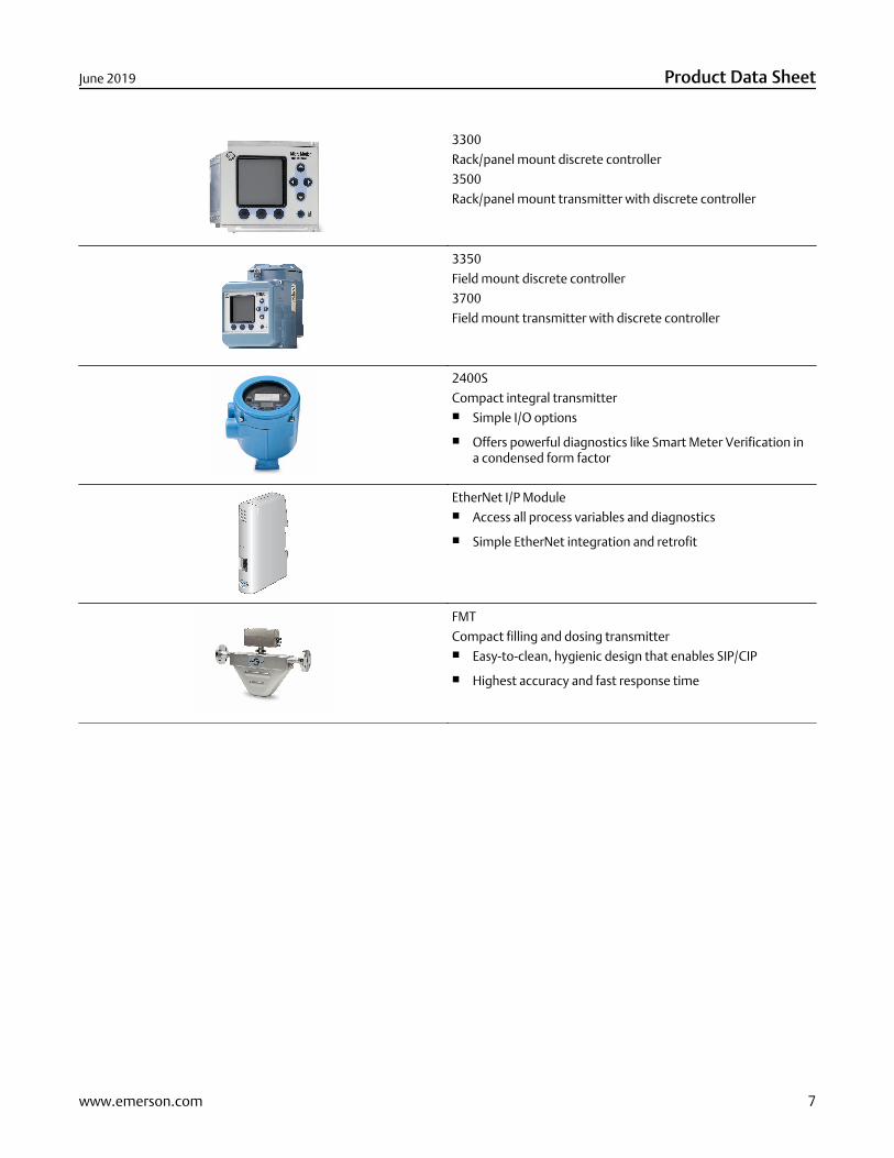
3300
Rack/panel mount discrete controller
3500
Rack/panel mount transmitter with discrete controller
3350
Field mount discrete controller
3700
Field mount transmitter with discrete controller
2400S
Compact integral transmitter■ Simple I/O options
■ Offers powerful diagnostics like Smart Meter Verification ina condensed form factor
EtherNet I/P Module■ Access all process variables and diagnostics
■ Simple EtherNet integration and retrofit
FMT
Compact filling and dosing transmitter■ Easy-to-clean, hygienic design that enables SIP/CIP
■ Highest accuracy and fast response time
June 2019 Product Data Sheet
www.emerson.com 7

Transmitter and controller specificationsTable 6: Output variables
Transmitter Mass / volumeflow
Net productcontent / flow(1)(2)
Temperature Density Concentration(2)
1500 ●
1700 ●
2400S ● ● ● ● ●
2500 ● ● ● ● ●
2700 ● ● ● ● ●
FMT ● ● ●
3300 ●
3350 ●
3500 ● ● ● ● ●
3700 ● ● ● ● ●
4200 ● ● ● ●
5700 ● ● ● ● ●
● Supported on all models
(1) Flow rate of product based on concentration. For example, in a dissolved sugar solution, the measurement is the flow rate of the sugar alone, andin a net oil application, the measurement is water alone or oil alone.
(2) Optional feature.
Table 7: Local display
Transmitter 2-line Graphical
1500
1700 ●
2400S ●
2500
2700 ●
FMT
3300 ●
3350 ●
3500 ●
3700 ●
4200 ●
5700 ●
● Supported on all models
Product Data Sheet June 2019
8 www.emerson.com
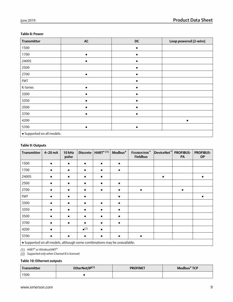
Table 8: Power
Transmitter AC DC Loop powered (2-wire)
1500 ●
1700 ● ●
2400S ● ●
2500 ●
2700 ● ●
FMT ●
K-Series ● ●
3300 ● ●
3350 ● ●
3500 ● ●
3700 ● ●
4200 ●
5700 ● ●
● Supported on all models.
Table 9: Outputs
Transmitter 4–20 mA 10 kHzpulse
Discrete HART® (1) Modbus® FOUNDATION™
FieldbusDeviceNet™ PROFIBUS-
PAPROFIBUS-
DP
1500 ● ● ● ● ●
1700 ● ● ● ● ●
2400S ● ● ● ● ● ●
2500 ● ● ● ● ●
2700 ● ● ● ● ● ● ●
FMT ● ● ● ● ●
3300 ● ● ● ● ●
3350 ● ● ● ● ●
3500 ● ● ● ● ●
3700 ● ● ● ● ●
4200 ● ●(2) ●
5700 ● ● ● ● ● ●
● Supported on all models, although some combinations may be unavailable.
(1) HART® or WirelessHART®
(2) Supported only when Channel B is licensed.
Table 10: Ethernet outputs
Transmitter EtherNet/IP(1) PROFINET Modbus® TCP
1500 ●
June 2019 Product Data Sheet
www.emerson.com 9
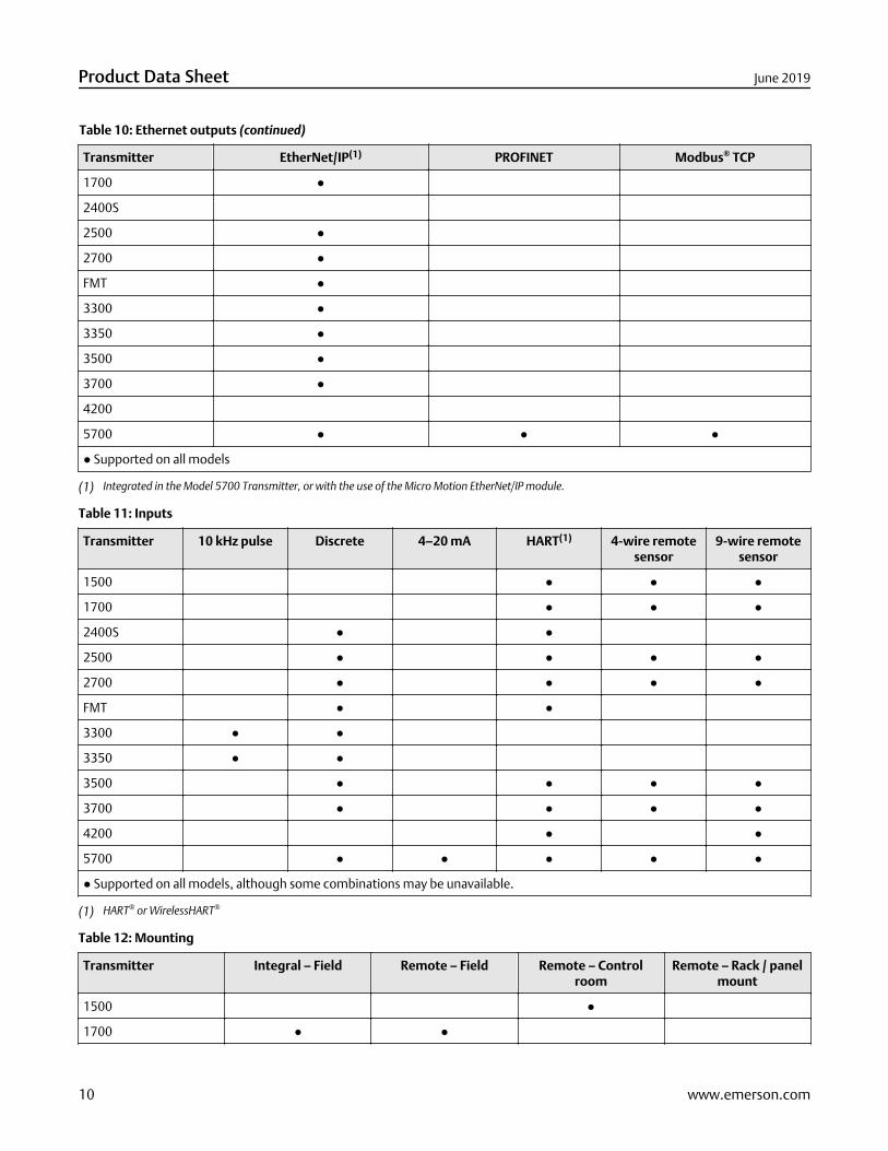
Table 10: Ethernet outputs (continued)
Transmitter EtherNet/IP(1) PROFINET Modbus® TCP
1700 ●
2400S
2500 ●
2700 ●
FMT ●
3300 ●
3350 ●
3500 ●
3700 ●
4200
5700 ● ● ●
● Supported on all models
(1) Integrated in the Model 5700 Transmitter, or with the use of the Micro Motion EtherNet/IP module.
Table 11: Inputs
Transmitter 10 kHz pulse Discrete 4–20 mA HART(1) 4-wire remotesensor
9-wire remotesensor
1500 ● ● ●
1700 ● ● ●
2400S ● ●
2500 ● ● ● ●
2700 ● ● ● ●
FMT ● ●
3300 ● ●
3350 ● ●
3500 ● ● ● ●
3700 ● ● ● ●
4200 ● ●
5700 ● ● ● ● ●
● Supported on all models, although some combinations may be unavailable.
(1) HART® or WirelessHART®
Table 12: Mounting
Transmitter Integral – Field Remote – Field Remote – Controlroom
Remote – Rack / panelmount
1500 ●
1700 ● ●
Product Data Sheet June 2019
10 www.emerson.com
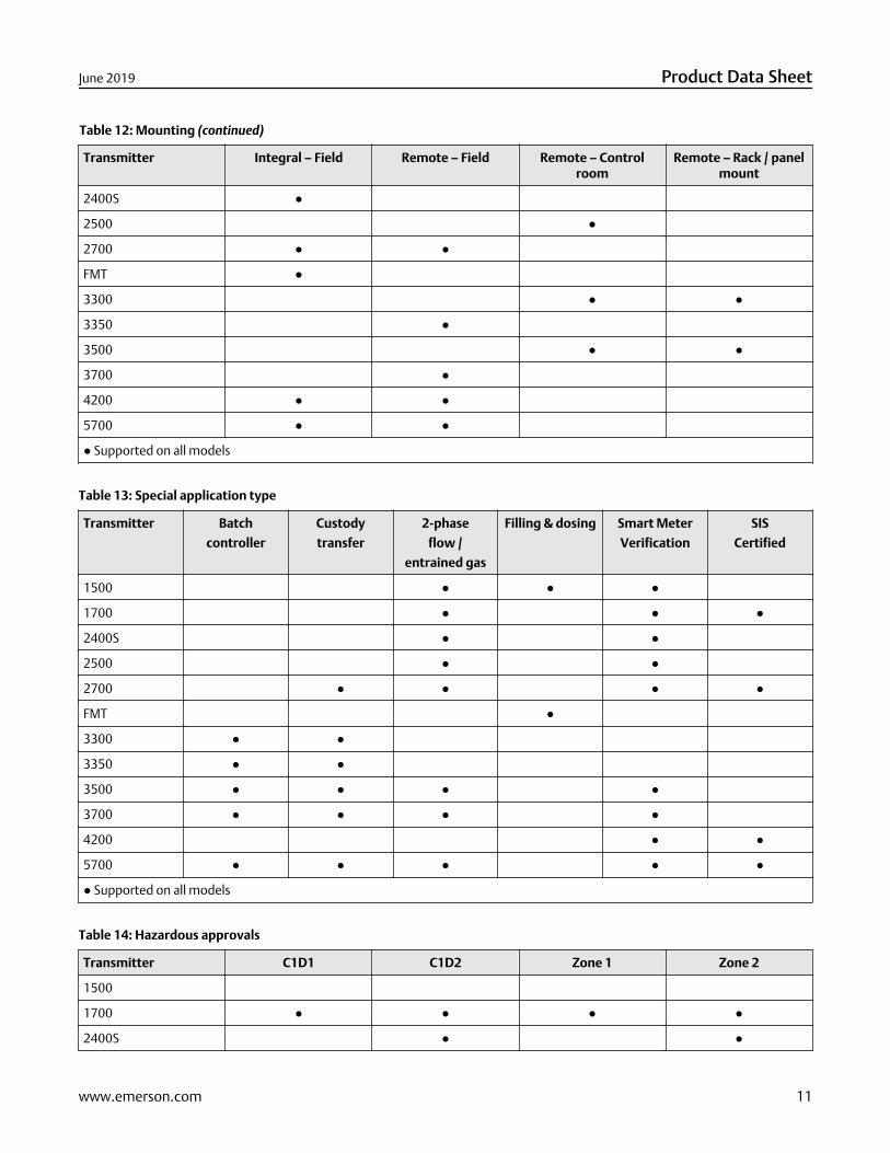
Table 12: Mounting (continued)
Transmitter Integral – Field Remote – Field Remote – Controlroom
Remote – Rack / panelmount
2400S ●
2500 ●
2700 ● ●
FMT ●
3300 ● ●
3350 ●
3500 ● ●
3700 ●
4200 ● ●
5700 ● ●
● Supported on all models
Table 13: Special application type
Transmitter Batch
controller
Custody
transfer
2-phase
flow /
entrained gas
Filling & dosing Smart Meter
Verification
SIS
Certified
1500 ● ● ●
1700 ● ● ●
2400S ● ●
2500 ● ●
2700 ● ● ● ●
FMT ●
3300 ● ●
3350 ● ●
3500 ● ● ● ●
3700 ● ● ● ●
4200 ● ●
5700 ● ● ● ● ●
● Supported on all models
Table 14: Hazardous approvals
Transmitter C1D1 C1D2 Zone 1 Zone 2
1500
1700 ● ● ● ●
2400S ● ●
June 2019 Product Data Sheet
www.emerson.com 11
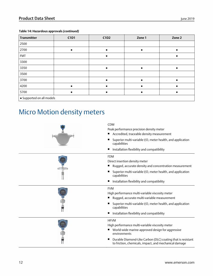
Table 14: Hazardous approvals (continued)
Transmitter C1D1 C1D2 Zone 1 Zone 2
2500
2700 ● ● ● ●
FMT ● ●
3300
3350 ● ● ●
3500
3700 ● ● ●
4200 ● ● ● ●
5700 ● ● ● ●
● Supported on all models
Micro Motion density meters
CDM
Peak performance precision density meter■ Accredited, traceable density measurement
■ Superior multi-variable I/O, meter health, and applicationcapabilities
■ Installation flexibility and compatibility
FDM
Direct insertion density meter■ Rugged, accurate density and concentration measurement
■ Superior multi-variable I/O, meter health, and applicationcapabilities
■ Installation flexibility and compatibility
FVM
High performance multi-variable viscosity meter■ Rugged, accurate multi-variable measurement
■ Superior multi-variable I/O, meter health, and applicationcapabilities
■ Installation flexibility and compatibility
HFVM
High performance multi-variable viscosity meter■ World-wide marine-approved design for aggressive
environments
■ Durable Diamond-Like Carbon (DLC) coating that is resistantto friction, chemicals, impact, and mechanical damage
Product Data Sheet June 2019
12 www.emerson.com
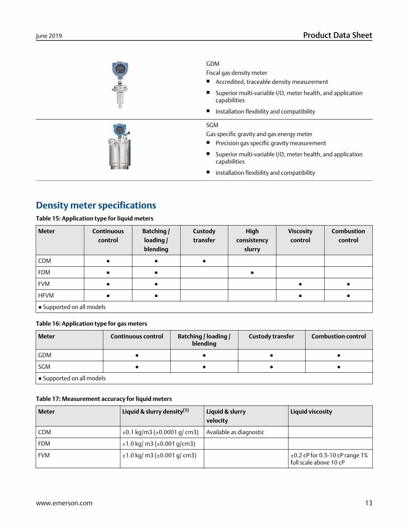
GDM
Fiscal gas density meter■ Accredited, traceable density measurement
■ Superior multi-variable I/O, meter health, and applicationcapabilities
■ Installation flexibility and compatibility
SGM
Gas specific gravity and gas energy meter■ Precision gas specific gravity measurement
■ Superior multi-variable I/O, meter health, and applicationcapabilities
■ installation flexibility and compatibility
Density meter specificationsTable 15: Application type for liquid meters
Meter Continuous
control
Batching /
loading /
blending
Custody
transfer
High
consistency
slurry
Viscosity
control
Combustion
control
CDM ● ● ●
FDM ● ● ●
FVM ● ● ● ●
HFVM ● ● ● ●
● Supported on all models
Table 16: Application type for gas meters
Meter Continuous control Batching / loading /blending
Custody transfer Combustion control
GDM ● ● ● ●
SGM ● ● ● ●
● Supported on all models
Table 17: Measurement accuracy for liquid meters
Meter Liquid & slurry density(1) Liquid & slurry
velocity
Liquid viscosity
CDM ±0.1 kg/m3 (±0.0001 g/ cm3) Available as diagnostic
FDM ±1.0 kg/ m3 (±0.001 g/cm3)
FVM ±1.0 kg/ m3 (±0.001 g/ cm3) ±0.2 cP for 0.5-10 cP range 1%full scale above 10 cP
June 2019 Product Data Sheet
www.emerson.com 13
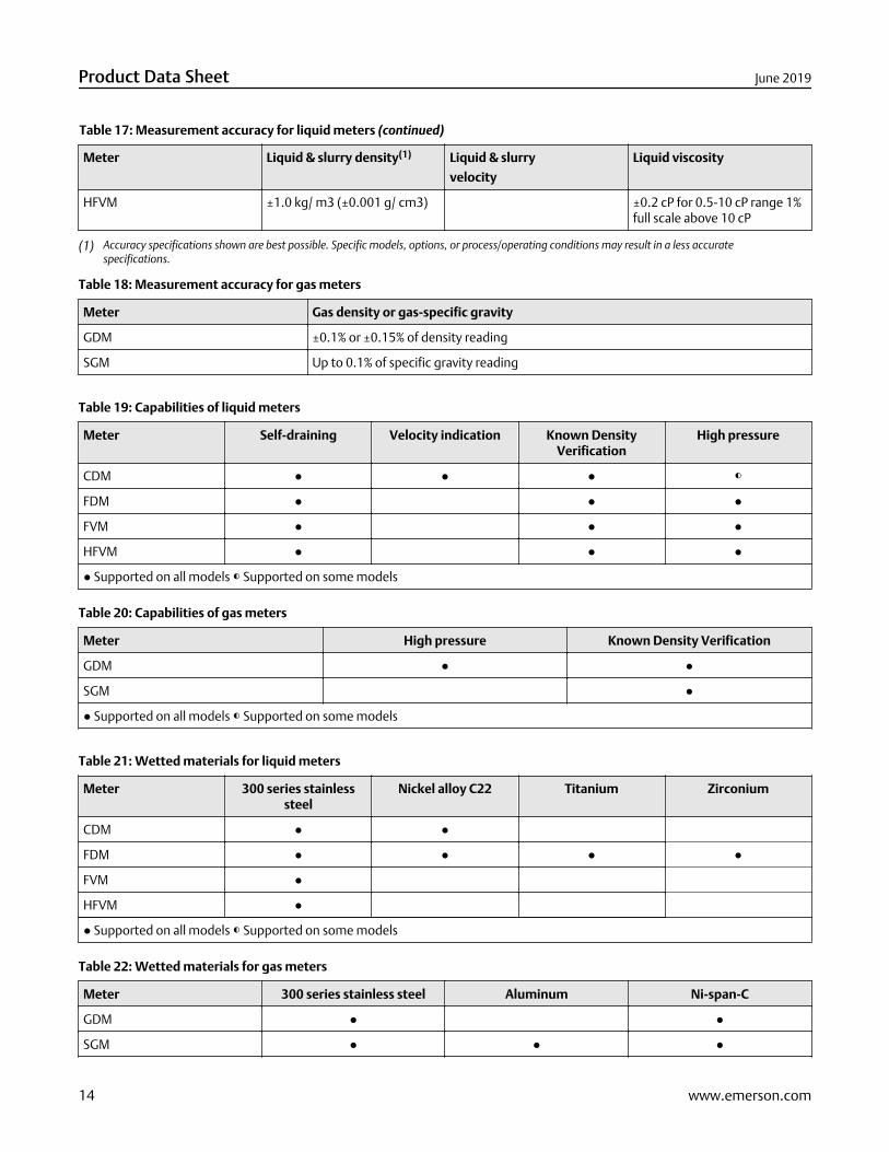
Table 17: Measurement accuracy for liquid meters (continued)
Meter Liquid & slurry density(1) Liquid & slurry
velocity
Liquid viscosity
HFVM ±1.0 kg/ m3 (±0.001 g/ cm3) ±0.2 cP for 0.5-10 cP range 1%full scale above 10 cP
(1) Accuracy specifications shown are best possible. Specific models, options, or process/operating conditions may result in a less accuratespecifications.
Table 18: Measurement accuracy for gas meters
Meter Gas density or gas-specific gravity
GDM ±0.1% or ±0.15% of density reading
SGM Up to 0.1% of specific gravity reading
Table 19: Capabilities of liquid meters
Meter Self-draining Velocity indication Known DensityVerification
High pressure
CDM ● ● ● ◐
FDM ● ● ●
FVM ● ● ●
HFVM ● ● ●
● Supported on all models ◐ Supported on some models
Table 20: Capabilities of gas meters
Meter High pressure Known Density Verification
GDM ● ●
SGM ●
● Supported on all models ◐ Supported on some models
Table 21: Wetted materials for liquid meters
Meter 300 series stainlesssteel
Nickel alloy C22 Titanium Zirconium
CDM ● ●
FDM ● ● ● ●
FVM ●
HFVM ●
● Supported on all models ◐ Supported on some models
Table 22: Wetted materials for gas meters
Meter 300 series stainless steel Aluminum Ni-span-C
GDM ● ●
SGM ● ● ●
Product Data Sheet June 2019
14 www.emerson.com
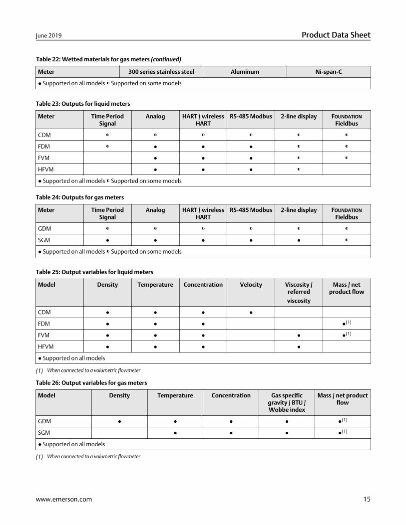
Table 22: Wetted materials for gas meters (continued)
Meter 300 series stainless steel Aluminum Ni-span-C
● Supported on all models ◐ Supported on some models
Table 23: Outputs for liquid meters
Meter Time PeriodSignal
Analog HART / wirelessHART
RS-485 Modbus 2-line display FOUNDATION
Fieldbus
CDM ◐ ◐ ◐ ◐ ◐ ◐
FDM ◐ ● ● ● ◐ ◐
FVM ● ● ● ◐ ◐
HFVM ● ● ● ◐
● Supported on all models ◐ Supported on some models
Table 24: Outputs for gas meters
Meter Time PeriodSignal
Analog HART / wirelessHART
RS-485 Modbus 2-line display FOUNDATION
Fieldbus
GDM ◐ ◐ ◐ ◐ ◐ ◐
SGM ● ● ● ● ● ◐
● Supported on all models ◐ Supported on some models
Table 25: Output variables for liquid meters
Model Density Temperature Concentration Velocity Viscosity /referred
viscosity
Mass / netproduct flow
CDM ● ● ● ●
FDM ● ● ● ●(1)
FVM ● ● ● ● ●(1)
HFVM ● ● ● ●
● Supported on all models
(1) When connected to a volumetric flowmeter
Table 26: Output variables for gas meters
Model Density Temperature Concentration Gas specificgravity / BTU /Wobbe index
Mass / net productflow
GDM ● ● ● ● ●(1)
SGM ● ● ● ●(1)
● Supported on all models
(1) When connected to a volumetric flowmeter
June 2019 Product Data Sheet
www.emerson.com 15
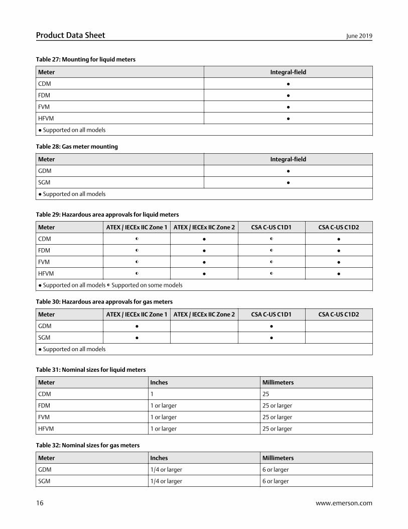
Table 27: Mounting for liquid meters
Meter Integral-field
CDM ●
FDM ●
FVM ●
HFVM ●
● Supported on all models
Table 28: Gas meter mounting
Meter Integral-field
GDM ●
SGM ●
● Supported on all models
Table 29: Hazardous area approvals for liquid meters
Meter ATEX / IECEx IIC Zone 1 ATEX / IECEx IIC Zone 2 CSA C-US C1D1 CSA C-US C1D2
CDM ◐ ● ◐ ●
FDM ◐ ● ◐ ●
FVM ◐ ● ◐ ●
HFVM ◐ ● ◐ ●
● Supported on all models ◐ Supported on some models
Table 30: Hazardous area approvals for gas meters
Meter ATEX / IECEx IIC Zone 1 ATEX / IECEx IIC Zone 2 CSA C-US C1D1 CSA C-US C1D2
GDM ● ●
SGM ● ●
● Supported on all models
Table 31: Nominal sizes for liquid meters
Meter Inches Millimeters
CDM 1 25
FDM 1 or larger 25 or larger
FVM 1 or larger 25 or larger
HFVM 1 or larger 25 or larger
Table 32: Nominal sizes for gas meters
Meter Inches Millimeters
GDM 1/4 or larger 6 or larger
SGM 1/4 or larger 6 or larger
Product Data Sheet June 2019
16 www.emerson.com

Performance specifications
Reference operating conditionsFor determining the performance capabilities of our meters, the following conditions were observed/used:
■ Water at 68 °F (20.0 °C) to 77 °F (25.0 °C) and 14.5 psig (1.000 barg) to 29 psig (2.00 barg)
■ Air and Natural Gas at 68 °F (20.0 °C) to 77 °F (25.0 °C) and 500 psig (34.47 barg) to1,450 psig (99.97 barg)
■ Accuracy is verified by industry leading accredited calibration stands according to ISO 17025
Accuracy and repeatability on liquids and slurries
Sensor Accuracy(1) Mass/volumeflow repeatability
Mass flow(2) Volume flow(2)
ELITE ±0.05% ±0.05% 0.025%
F-Series ±0.10% ±0.1% 0.05%
H-Series ±0.10% ±0.1% 0.05%
LF-Series ±0.50% ±0.50% 0.05%
T-Series ±0.15% ±0.25% 0.05%
TA-Series ±0.10% of rate ±z.s. ±0.10% of rate ±z.s. ±0.05% ± [½ (zero stability /flow rate) × 100] % of rate
R-Series ±0.40% ±0.4% 0.20%
HPC010 ±0.20% ±0.20% 0.10%
(1) Flow rate accuracies are base percentages. For total accuracy see Measurement accuracy for liquid meters. Stated accuracy includes thecombined effects of repeatability, linearity, and hysteresis.
(2) Flow rate accuracies may vary with calibration option selected. Consult the sensor Product Data Sheet for details.
Accuracy and repeatability on gases
Sensor Accuracy(1) Repeatability
ELITE ±0.25% of rate 0.20% of rate
CNG-Series ±0.50% of rate 0.25% of rate
F-Series ±0.50% of rate 0.25% of rate
H-Series ±0.50% of rate 0.25% of rate
LF-Series ±0.50% of rate 0.05% of rate(2)
T-Series ±0.50% of rate 0.05% of rate
TA-Series ±0.50% of rate 0.05% of rate
R-Series ±0.75% of rate ±0.5% of rate
HPC010 ±0.50% of rate ±0.25% of rate
(1) Flow accuracies are base percentages. For total accuracy see Table 18. Stated accuracy includes the combined effects of repeatability, linearity,and hysteresis.
June 2019 Product Data Sheet
www.emerson.com 17
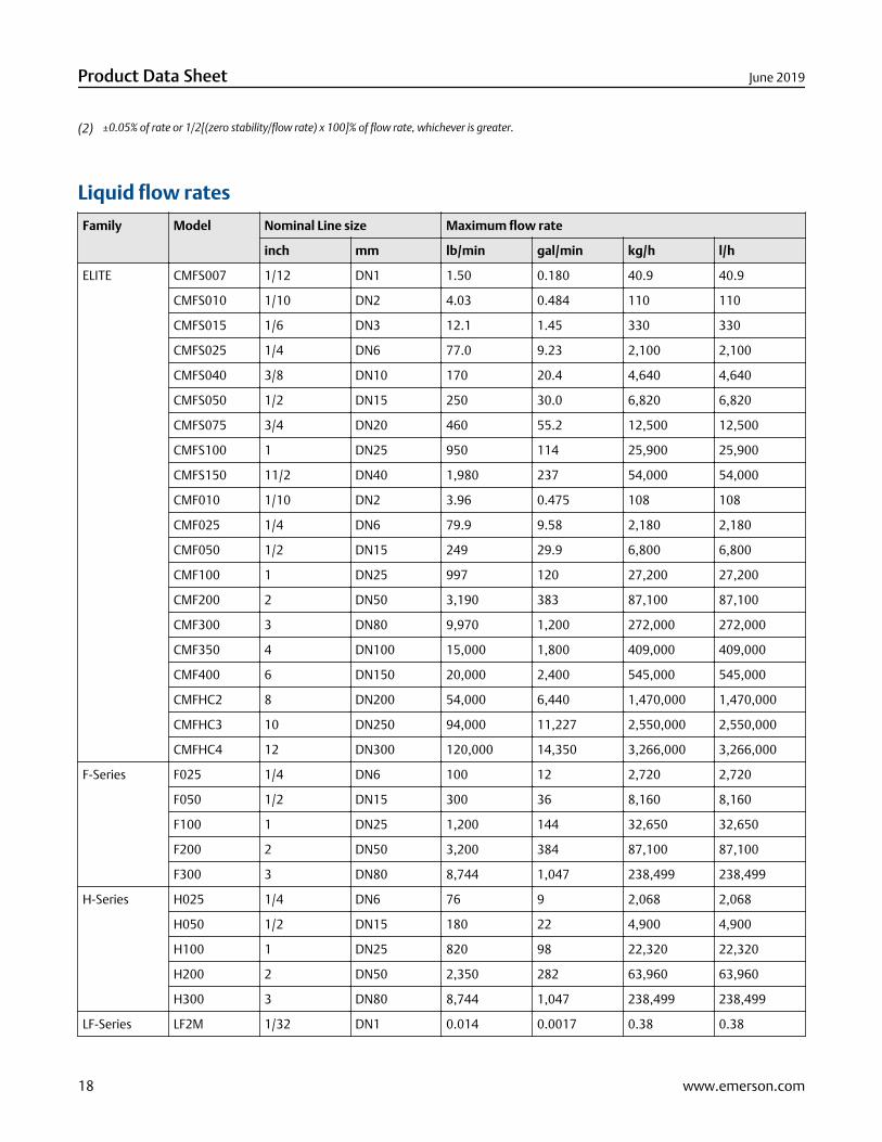
(2) ±0.05% of rate or 1/2[(zero stability/flow rate) x 100]% of flow rate, whichever is greater.
Liquid flow rates
Family Model Nominal Line size Maximum flow rate
inch mm lb/min gal/min kg/h l/h
ELITE CMFS007 1/12 DN1 1.50 0.180 40.9 40.9
CMFS010 1/10 DN2 4.03 0.484 110 110
CMFS015 1/6 DN3 12.1 1.45 330 330
CMFS025 1/4 DN6 77.0 9.23 2,100 2,100
CMFS040 3/8 DN10 170 20.4 4,640 4,640
CMFS050 1/2 DN15 250 30.0 6,820 6,820
CMFS075 3/4 DN20 460 55.2 12,500 12,500
CMFS100 1 DN25 950 114 25,900 25,900
CMFS150 11/2 DN40 1,980 237 54,000 54,000
CMF010 1/10 DN2 3.96 0.475 108 108
CMF025 1/4 DN6 79.9 9.58 2,180 2,180
CMF050 1/2 DN15 249 29.9 6,800 6,800
CMF100 1 DN25 997 120 27,200 27,200
CMF200 2 DN50 3,190 383 87,100 87,100
CMF300 3 DN80 9,970 1,200 272,000 272,000
CMF350 4 DN100 15,000 1,800 409,000 409,000
CMF400 6 DN150 20,000 2,400 545,000 545,000
CMFHC2 8 DN200 54,000 6,440 1,470,000 1,470,000
CMFHC3 10 DN250 94,000 11,227 2,550,000 2,550,000
CMFHC4 12 DN300 120,000 14,350 3,266,000 3,266,000
F-Series F025 1/4 DN6 100 12 2,720 2,720
F050 1/2 DN15 300 36 8,160 8,160
F100 1 DN25 1,200 144 32,650 32,650
F200 2 DN50 3,200 384 87,100 87,100
F300 3 DN80 8,744 1,047 238,499 238,499
H-Series H025 1/4 DN6 76 9 2,068 2,068
H050 1/2 DN15 180 22 4,900 4,900
H100 1 DN25 820 98 22,320 22,320
H200 2 DN50 2,350 282 63,960 63,960
H300 3 DN80 8,744 1,047 238,499 238,499
LF-Series LF2M 1/32 DN1 0.014 0.0017 0.38 0.38
Product Data Sheet June 2019
18 www.emerson.com

Family Model Nominal Line size Maximum flow rate
inch mm lb/min gal/min kg/h l/h
LF3M 1/16 DN2 0.037 0.0043 1.00 1.00
LF4M 1/8 DN3 0.992 0.119 27.00 27.00
T-Series T025 1/4 DN6 25 3 680 680
T050 1/2 DN15 140 17 3,800 3,800
T075 3/4 DN20 500 60 14,000 14,000
T100 1 DN25 1,100 132 30,000 30,000
T150 11/2 DN40 3,200 384 87,000 87,000
TA-Series TA010T 0.0198 2.49 12.9 1.5 350 350
TA025T 0.24 6.1 44.1 5.3 1,200 1,200
TA050T 0.5 13 110.2 13.2 3,000 3,000
TA075T 0.75 19 220.5 26.5 6,000 6,000
TA100T 0.98 24.9 661.4 79.4 18,000 18,000
TA200T 2.00 51 1102.3 132.3 30,000 30,000
R-Series R025 1/4 DN6 100 12 2,720 2,720
R050 1/2 DN15 300 36 8,160 8,160
R100 1 DN25 1,200 144 32,650 32,650
R200 2 DN50 3,200 384 87,100 87,100
R300 3 DN80 8,744 1,047 238,499 238,499
CDM CDM100 1 DN25 625 75 17,000 17,000
HPC HPC010P ± 1/8 ± 3 8.8 0.22 240 49.0
FDM, FVM, HFVM Line sizes and flow rates are installation-dependent. Contact your sales representative.
Gas flow ratesWhen selecting sensors for gas applications, pressure drop through the sensor is dependent upon operating temperature,pressure, and fluid composition. Therefore, when selecting a sensor for any particular gas application, it is highly recommendedthat each sensor be sized using the Sizing and Selection Tool at the Micro Motion web site (Discover Flow Measurement Sizing andSelection Tool) for detailed information regarding performance and sizing of the meters.
The below table indicates flow rates that produce approximately 25 psi (1.72 bar) pressure drop on gulf coast natural gas, exceptfor the T-Series sensor, that produces approximately 10 psi (0.69 bar) pressure drop on gulf coast natural gas.
Gas flow rate table
NoteThe following table assumes natural gas with molecular weight of 16.799 at 60 °F (15.6 °C) and 1,014.7 psi (69.961 bar).
Family Model Mass flow Volume flow
lb/min kg/h SCFM(1) SCFH(2) SCCM Nm3/h l/h
ELITE CMFS007 0.5 15 12 20
June 2019 Product Data Sheet
www.emerson.com 19
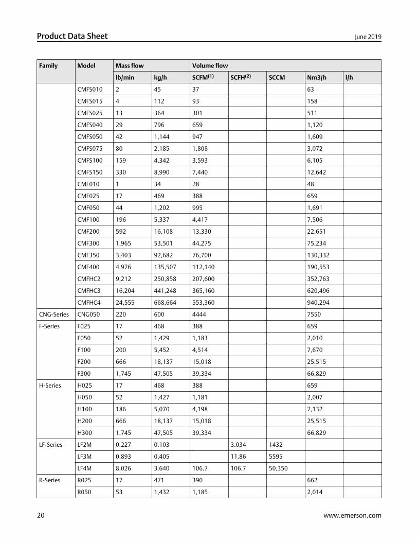
Family Model Mass flow Volume flow
lb/min kg/h SCFM(1) SCFH(2) SCCM Nm3/h l/h
CMFS010 2 45 37 63
CMFS015 4 112 93 158
CMFS025 13 364 301 511
CMFS040 29 796 659 1,120
CMFS050 42 1,144 947 1,609
CMFS075 80 2,185 1,808 3,072
CMFS100 159 4,342 3,593 6,105
CMFS150 330 8,990 7,440 12,642
CMF010 1 34 28 48
CMF025 17 469 388 659
CMF050 44 1,202 995 1,691
CMF100 196 5,337 4,417 7,506
CMF200 592 16,108 13,330 22,651
CMF300 1,965 53,501 44,275 75,234
CMF350 3,403 92,682 76,700 130,332
CMF400 4,976 135,507 112,140 190,553
CMFHC2 9,212 250,858 207,600 352,763
CMFHC3 16,204 441,248 365,160 620,496
CMFHC4 24,555 668,664 553,360 940,294
CNG-Series CNG050 220 600 4444 7550
F-Series F025 17 468 388 659
F050 52 1,429 1,183 2,010
F100 200 5,452 4,514 7,670
F200 666 18,137 15,018 25,515
F300 1,745 47,505 39,334 66,829
H-Series H025 17 468 388 659
H050 52 1,427 1,181 2,007
H100 186 5,070 4,198 7,132
H200 666 18,137 15,018 25,515
H300 1,745 47,505 39,334 66,829
LF-Series LF2M 0.227 0.103 3.034 1432
LF3M 0.893 0.405 11.86 5595
LF4M 8.026 3.640 106.7 106.7 50,350
R-Series R025 17 471 390 662
R050 53 1,432 1,185 2,014
Product Data Sheet June 2019
20 www.emerson.com
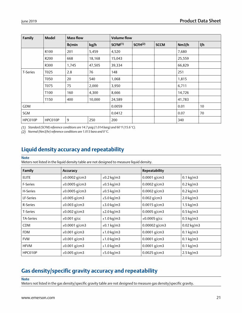
Family Model Mass flow Volume flow
lb/min kg/h SCFM(1) SCFH(2) SCCM Nm3/h l/h
R100 201 5,459 4,520 7,680
R200 668 18,168 15,043 25,559
R300 1,745 47,505 39,334 66,829
T-Series T025 2.8 76 148 251
T050 20 540 1,068 1,815
T075 75 2,000 3,950 6,711
T100 160 4,300 8,666 14,726
T150 400 10,000 24,589 41,783
GDM 0.0059 0.01 10
SGM 0.0412 0.07 70
HPC010P HPC010P 9 250 200 340
(1) Standard (SCFM) reference conditions are 14.7 psig (1.014 barg) and 60 °F (15.6 °C).(2) Normal (Nm3/hr) reference conditions are 1.013 bara and 0 °C.
Liquid density accuracy and repeatabilityNoteMeters not listed in the liquid density table are not designed to measure liquid density.
Family Accuracy Repeatability
ELITE ±0.0002 g/cm3 ±0.2 kg/m3 0.0001 g/cm3 0.1 kg/m3
F-Series ±0.0005 g/cm3 ±0.5 kg/m3 0.0002 g/cm3 0.2 kg/m3
H-Series ±0.0005 g/cm3 ±0.5 kg/m3 0.0002 g/cm3 0.2 kg/m3
LF-Series ±0.005 g/cm3 ±5.0 kg/m3 0.002 g/cm3 2.0 kg/m3
R-Series ±0.003 g/cm3 ±3.0 kg/m3 0.0015 g/cm3 1.5 kg/m3
T-Series ±0.002 g/cm3 ±2.0 kg/m3 0.0005 g/cm3 0.5 kg/m3
TA-Series ±0.001 g/cc ±1.0 kg/m3 ±0.0005 g/cc 0.5 kg/m3
CDM ±0.0001 g/cm3 ±0.1 kg/m3 0.00002 g/cm3 0.02 kg/m3
FDM ±0.001 g/cm3 ±1.0 kg/m3 0.0001 g/cm3 0.1 kg/m3
FVM ±0.001 g/cm3 ±1.0 kg/m3 0.0001 g/cm3 0.1 kg/m3
HFVM ±0.001 g/cm3 ±1.0 kg/m3 0.0001 g/cm3 0.1 kg/m3
HPC010P ±0.005 g/cm3 ±5.0 kg/m3 0.0025 g/cm3 2.5 kg/m3
Gas density/specific gravity accuracy and repeatabilityNoteMeters not listed in the gas density/specific gravity table are not designed to measure gas density/specific gravity.
June 2019 Product Data Sheet
www.emerson.com 21
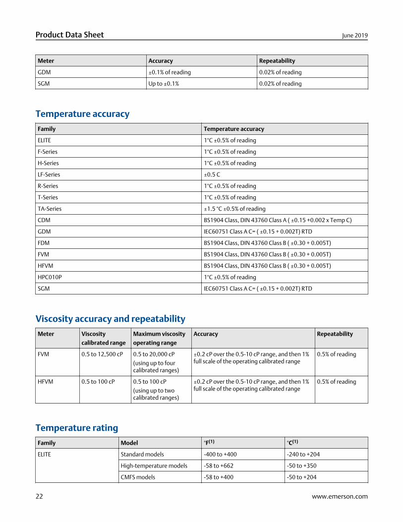
Meter Accuracy Repeatability
GDM ±0.1% of reading 0.02% of reading
SGM Up to ±0.1% 0.02% of reading
Temperature accuracy
Family Temperature accuracy
ELITE 1°C ±0.5% of reading
F-Series 1°C ±0.5% of reading
H-Series 1°C ±0.5% of reading
LF-Series ±0.5 C
R-Series 1°C ±0.5% of reading
T-Series 1°C ±0.5% of reading
TA-Series ±1.5 °C ±0.5% of reading
CDM BS1904 Class, DIN 43760 Class A ( ±0.15 +0.002 x Temp C)
GDM IEC60751 Class A C= ( ±0.15 + 0.002T) RTD
FDM BS1904 Class, DIN 43760 Class B ( ±0.30 + 0.005T)
FVM BS1904 Class, DIN 43760 Class B ( ±0.30 + 0.005T)
HFVM BS1904 Class, DIN 43760 Class B ( ±0.30 + 0.005T)
HPC010P 1°C ±0.5% of reading
SGM IEC60751 Class A C= ( ±0.15 + 0.002T) RTD
Viscosity accuracy and repeatability
Meter Viscosity
calibrated range
Maximum viscosity
operating range
Accuracy Repeatability
FVM 0.5 to 12,500 cP 0.5 to 20,000 cP
(using up to fourcalibrated ranges)
±0.2 cP over the 0.5-10 cP range, and then 1%full scale of the operating calibrated range
0.5% of reading
HFVM 0.5 to 100 cP 0.5 to 100 cP
(using up to twocalibrated ranges)
±0.2 cP over the 0.5-10 cP range, and then 1%full scale of the operating calibrated range
0.5% of reading
Temperature rating
Family Model °F(1) °C(1)
ELITE Standard models -400 to +400 -240 to +204
High-temperature models -58 to +662 -50 to +350
CMFS models -58 to +400 -50 to +204
Product Data Sheet June 2019
22 www.emerson.com
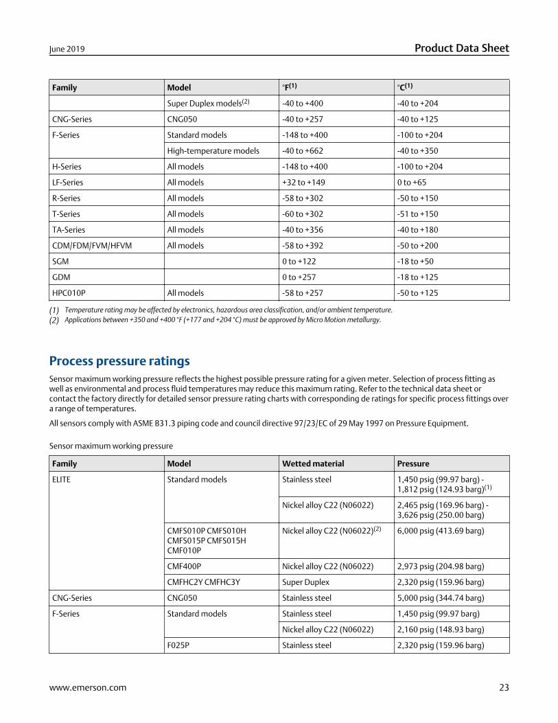
Family Model °F(1) °C(1)
Super Duplex models(2) -40 to +400 -40 to +204
CNG-Series CNG050 -40 to +257 -40 to +125
F-Series Standard models -148 to +400 -100 to +204
High-temperature models -40 to +662 -40 to +350
H-Series All models -148 to +400 -100 to +204
LF-Series All models +32 to +149 0 to +65
R-Series All models -58 to +302 -50 to +150
T-Series All models -60 to +302 -51 to +150
TA-Series All models -40 to +356 -40 to +180
CDM/FDM/FVM/HFVM All models -58 to +392 -50 to +200
SGM 0 to +122 -18 to +50
GDM 0 to +257 -18 to +125
HPC010P All models -58 to +257 -50 to +125
(1) Temperature rating may be affected by electronics, hazardous area classification, and/or ambient temperature.(2) Applications between +350 and +400 °F (+177 and +204 °C) must be approved by Micro Motion metallurgy.
Process pressure ratingsSensor maximum working pressure reflects the highest possible pressure rating for a given meter. Selection of process fitting aswell as environmental and process fluid temperatures may reduce this maximum rating. Refer to the technical data sheet orcontact the factory directly for detailed sensor pressure rating charts with corresponding de ratings for specific process fittings overa range of temperatures.
All sensors comply with ASME B31.3 piping code and council directive 97/23/EC of 29 May 1997 on Pressure Equipment.
Sensor maximum working pressure
Family Model Wetted material Pressure
ELITE Standard models Stainless steel 1,450 psig (99.97 barg) -1,812 psig (124.93 barg)(1)
Nickel alloy C22 (N06022) 2,465 psig (169.96 barg) -3,626 psig (250.00 barg)
CMFS010P CMFS010HCMFS015P CMFS015HCMF010P
Nickel alloy C22 (N06022)(2) 6,000 psig (413.69 barg)
CMF400P Nickel alloy C22 (N06022) 2,973 psig (204.98 barg)
CMFHC2Y CMFHC3Y Super Duplex 2,320 psig (159.96 barg)
CNG-Series CNG050 Stainless steel 5,000 psig (344.74 barg)
F-Series Standard models Stainless steel 1,450 psig (99.97 barg)
Nickel alloy C22 (N06022) 2,160 psig (148.93 barg)
F025P Stainless steel 2,320 psig (159.96 barg)
June 2019 Product Data Sheet
www.emerson.com 23
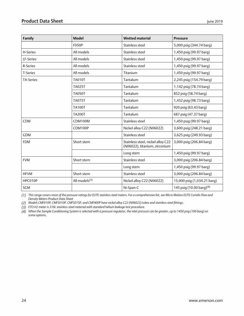
Family Model Wetted material Pressure
F050P Stainless steel 5,000 psig (344.74 barg)
H-Series All models Stainless steel 1,450 psig (99.97 barg)
LF-Series All models Stainless steel 1,450 psig (99.97 barg)
R-Series All models Stainless steel 1,450 psig (99.97 barg)
T-Series All models Titanium 1,450 psig (99.97 barg)
TA-Series TA010T Tantalum 2,245 psig (154.79 barg)
TA025T Tantalum 1,142 psig (78.74 barg)
TA050T Tantalum 852 psig (58.74 barg)
TA075T Tantalum 1,432 psig (98.73 barg)
TA100T Tantalum 920 psig (63.43 barg)
TA200T Tantalum 687 psig (47.37 barg)
CDM CDM100M Stainless steel 1,450 psig (99.97 barg)
CDM100P Nickel alloy C22 (N06022) 3,600 psig (248.21 barg)
GDM Stainless steel 3,625 psig (249.93 barg)
FDM Short stem Stainless steel, nickel alloy C22(N06022), titanium, zirconium
3,000 psig (206.84 barg)
Long stem 1,450 psig (99.97 barg)
FVM Short stem Stainless steel 3,000 psig (206.84 barg)
Long stem 1,450 psig (99.97 barg)
HFVM Short stem Stainless steel 3,000 psig (206.84 barg)
HPC010P All models(3) Nickel alloy C22 (N06022) 15,000 psig (1,034.21 barg)
SGM Ni-Span-C 145 psig (10.00 barg)(4)
(1) This range covers most of the pressure ratings for ELITE stainless steel meters. For a comprehensive list, see Micro Motion ELITE Coriolis Flow andDensity Meters Product Data Sheet
(2) Models CMF010P, CMFS010P, CMFS015P, and CMF400P have nickel alloy C22 (N06022) tubes and stainless steel fittings.(3) ETO H2 meter is 316L stainless steel material with standard helium leakage test procedure.(4) When the Sample Conditioning System is selected with a pressure regulator, the inlet pressure can be greater, up to 1450 psig (100 barg) on
some options.
Product Data Sheet June 2019
24 www.emerson.com

June 2019 Product Data Sheet
www.emerson.com 25

Product Data Sheet June 2019
26 www.emerson.com

June 2019 Product Data Sheet
www.emerson.com 27
PS-00232Rev. X
June 2019
Emerson Automation SolutionsWorldwide Headquarters7070 Winchester CircleBoulder, Colorado USA 80301T: +1 800-522-6277T: +1 303-527-5200F: +1 303-530-8459Mexico: 52 55 5809 5300Argentina: 54 11 4837 7000Brazil: 55 15 3413 8147Chile: 56 2 2928 4800
Emerson Automation SolutionsCentral Europe: +41 41 7686 111Eastern Europe: +41 41 7686 111Dubai: +971 4 811 8100Abu Dhabi: +971 2 697 2000Austria: +43 2236 607-0France: 0800 917 901Germany: +49 (0) 2173 3348 0Italy: 8008 77334The Netherlands: +31 318 495 555Belgium: +32 2 716 77 11Spain: 900 901 986U.K.: 0870 240 1978Russian/CIS: +7 495 981 9811
Emerson Automation SolutionsAustralia: (61) 3 9721 0200China: (86) 21 2892 9000India: (91) 22 6662 0566Japan: (81) 3 5769 6803South Korea: (82) 31 8034 0000Singapore: (65) 6 363 7766
©2019 Micro Motion, Inc. All rights reserved.
The Emerson logo is a trademark and service mark of Emerson Electric Co. Micro Motion, ELITE,ProLink, MVD and MVD Direct Connect marks are marks of one of the Emerson AutomationSolutions family of companies. All other marks are property of their respective owners.