micro motion f-series flow and density meters...product data sheet ps-00603, rev ae december 2019...
TRANSCRIPT
Product Data SheetPS-00603, Rev AE
December 2019
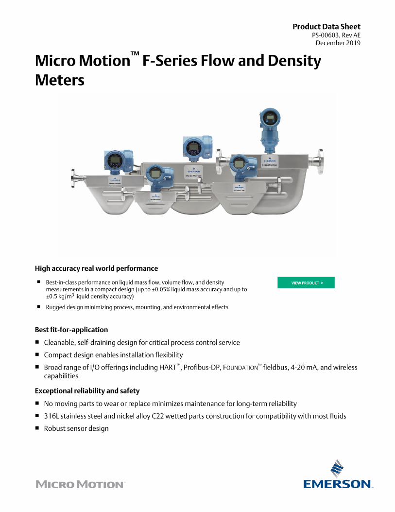
Micro Motion™ F-Series Flow and DensityMeters
High accuracy real world performance
■ Best-in-class performance on liquid mass flow, volume flow, and densitymeasurements in a compact design (up to ±0.05% liquid mass accuracy and up to±0.5 kg/m3 liquid density accuracy)
■ Rugged design minimizing process, mounting, and environmental effects
VIEW PRODUCT >
Best fit-for-application
■ Cleanable, self-draining design for critical process control service
■ Compact design enables installation flexibility
■ Broad range of I/O offerings including HART™, Profibus-DP, FOUNDATION™ fieldbus, 4-20 mA, and wirelesscapabilities
Exceptional reliability and safety
■ No moving parts to wear or replace minimizes maintenance for long-term reliability
■ 316L stainless steel and nickel alloy C22 wetted parts construction for compatibility with most fluids
■ Robust sensor design

Micro Motion F-Series flow and density metersMicro Motion F-Series meters deliver superb measurement with exceptional flow and density performance as well as outstandingreliability for use in critical process control environments.
Optimal flow and density fit for critical process applications■ High performance rugged measurement in a compact drainable design that maximizes process up time
■ Low frequency, high sensitivity fit-and-forget meter provides robust measurements even under demanding process conditions
■ Multiple line sizes provide an ideal platform for batching, distribution, allocation and intra-plant measurement applications
Smart Meter Verification™: advanced diagnostics for your entire system■ Included as standard, with the option to license flow range detection and other advanced meter health diagnostics
■ A comprehensive test that can be scheduled, run locally, or from the control room to provide confidence in your meterfunctionality and performance
■ Verifies that your meter performs as well as the day it was installed, giving you assurance in less than 90 seconds
■ Saves significant expenditure by reducing labor and extending or eliminating calibration intervals without interrupting theprocess
Industry-leading capabilities that unleash your process potential■ Available with the most extensive offering of transmitter and mounting options for maximum compatibility with your system
■ State of the art, ISO/IEC 17025 compliant calibration stands achieving ±0.014% uncertainty drive best in class measurementaccuracy
■ The most comprehensive communication protocol offering in the industry including Smart Wireless
■ True multi-variable technology measures necessary flow and density process variables simultaneously
Widest range of installation and process condition flexibility■ Featuring a low pressure drop, low weight design that reduces installation and commissioning costs
■ Unmatched MVD™ transmitter technology with digital signal processing (DSP) delivers the fastest response rates enablingaccurate batch and process measurement
■ Design flexibility enables operation at high temperature up to 662 °F (350 °C) or high pressure up to 6,237 psig (430 barg) tosolve your toughest measurement challenges
F-Series Flow and Density Meters December 2019
2 www.emerson.com
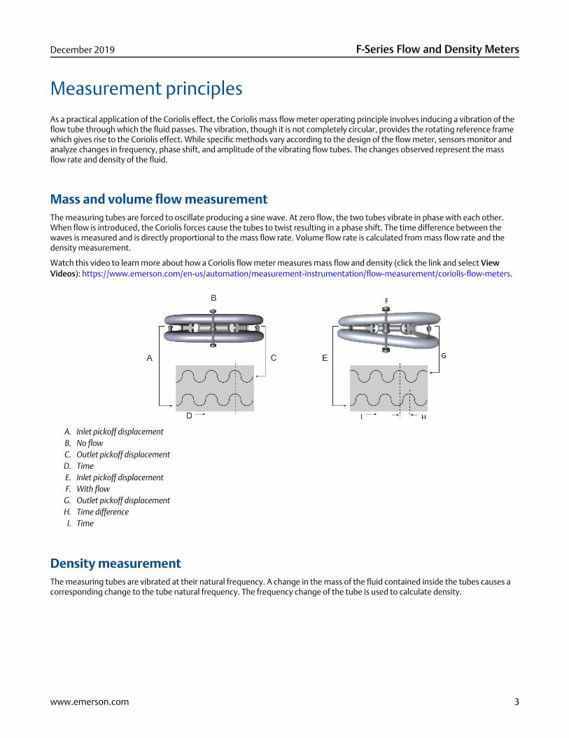
Measurement principlesAs a practical application of the Coriolis effect, the Coriolis mass flow meter operating principle involves inducing a vibration of theflow tube through which the fluid passes. The vibration, though it is not completely circular, provides the rotating reference framewhich gives rise to the Coriolis effect. While specific methods vary according to the design of the flow meter, sensors monitor andanalyze changes in frequency, phase shift, and amplitude of the vibrating flow tubes. The changes observed represent the massflow rate and density of the fluid.
Mass and volume flow measurementThe measuring tubes are forced to oscillate producing a sine wave. At zero flow, the two tubes vibrate in phase with each other.When flow is introduced, the Coriolis forces cause the tubes to twist resulting in a phase shift. The time difference between thewaves is measured and is directly proportional to the mass flow rate. Volume flow rate is calculated from mass flow rate and thedensity measurement.
Watch this video to learn more about how a Coriolis flow meter measures mass flow and density (click the link and select ViewVideos): https://www.emerson.com/en-us/automation/measurement-instrumentation/flow-measurement/coriolis-flow-meters.
A. Inlet pickoff displacementB. No flowC. Outlet pickoff displacementD. TimeE. Inlet pickoff displacementF. With flow
G. Outlet pickoff displacementH. Time difference
I. Time
Density measurementThe measuring tubes are vibrated at their natural frequency. A change in the mass of the fluid contained inside the tubes causes acorresponding change to the tube natural frequency. The frequency change of the tube is used to calculate density.
December 2019 F-Series Flow and Density Meters
www.emerson.com 3

Temperature measurementTemperature is a measured variable that is available as an output. The temperature is also used internal to the sensor tocompensate for temperature influences on Young’s Modulus of Elasticity.
Meter characteristics■ Measurement accuracy is a function of fluid mass flow rate independent of operating temperature, pressure, or composition.
However, pressure drop through the sensor is dependent upon operating temperature, pressure, and fluid composition.
■ Specifications and capabilities vary by model and certain models may have fewer available options. For detailed informationregarding performance and capabilities, either contact customer service or visit www.emerson.com/flowmeasurement.
■ The letter at the end of the base model code (for example F100S) represents wetted part material and/or applicationdesignation: S = stainless steel, H = nickel alloy C22, P = high pressure, A = high temperature 316L stainless steel, B = hightemperature nickel alloy C22. Detailed information about the complete product model codes are described later in thisdocument.
Performance specifications
Reference operating conditionsMicro Motion calibrates:
■ Water at 68 °F (20.0 °C) to 77 °F (25.0 °C) and 14.5 psig (1 barg) to 29 psig (2 barg)
■ Accuracy based on industry leading accredited calibration standards according to ISO/IEC 17025
■ A density range up to 3 g/cm³ (3,000 kg/m³)
Accuracy and repeatability
Accuracy and repeatability on liquids and slurries
Performance specifications Premium Enhanced Intermediate Basic
Mass and volume flow(1)(2) ±0.05% ±0.1% ±0.15% ±0.2%
Mass and volume repeatability(1) 0.025% 0.05% 0.075% 0.10%
Density accuracy(1) ±0.0005 g/cm³(±0.5 kg/m³)
±0.001 g/cm³ (±1 kg/m³) ±0.002 g/cm³(±2 kg/m³)
Density repeatability ±0.0002 g/cm³(±0.2 kg/m³)
±0.0005 g/cm³ (±0.5 kg/m³) ±0.001 g/cm³(±1 kg/m³)
Temperature accuracy ±1 °C ±0.5% of reading
Temperature repeatability ±0.2 °C
(1) Not available on all models.(2) Stated flow accuracy includes the combined effects of repeatability, linearity, and hysteresis.
F-Series Flow and Density Meters December 2019
4 www.emerson.com
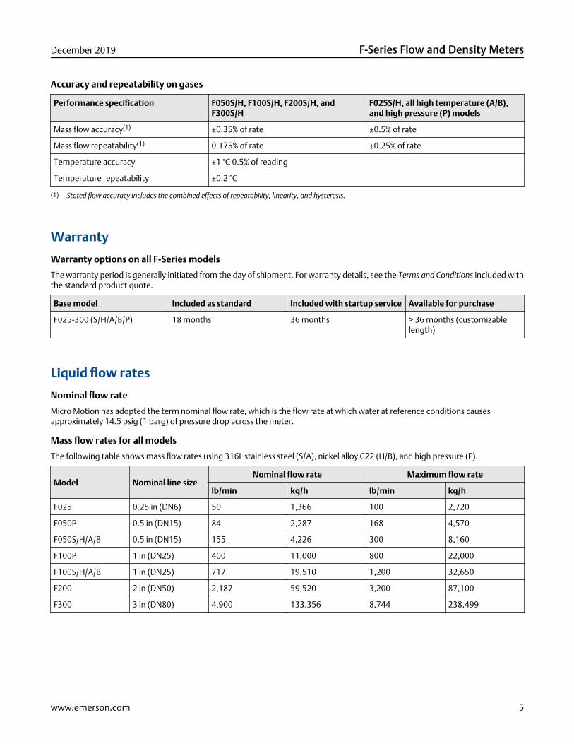
Accuracy and repeatability on gases
Performance specification F050S/H, F100S/H, F200S/H, andF300S/H
F025S/H, all high temperature (A/B),and high pressure (P) models
Mass flow accuracy(1) ±0.35% of rate ±0.5% of rate
Mass flow repeatability(1) 0.175% of rate ±0.25% of rate
Temperature accuracy ±1 °C 0.5% of reading
Temperature repeatability ±0.2 °C
(1) Stated flow accuracy includes the combined effects of repeatability, linearity, and hysteresis.
Warranty
Warranty options on all F-Series models
The warranty period is generally initiated from the day of shipment. For warranty details, see the Terms and Conditions included withthe standard product quote.
Base model Included as standard Included with startup service Available for purchase
F025-300 (S/H/A/B/P) 18 months 36 months > 36 months (customizablelength)
Liquid flow rates
Nominal flow rate
Micro Motion has adopted the term nominal flow rate, which is the flow rate at which water at reference conditions causesapproximately 14.5 psig (1 barg) of pressure drop across the meter.
Mass flow rates for all models
The following table shows mass flow rates using 316L stainless steel (S/A), nickel alloy C22 (H/B), and high pressure (P).
Model Nominal line sizeNominal flow rate Maximum flow rate
lb/min kg/h lb/min kg/h
F025 0.25 in (DN6) 50 1,366 100 2,720
F050P 0.5 in (DN15) 84 2,287 168 4,570
F050S/H/A/B 0.5 in (DN15) 155 4,226 300 8,160
F100P 1 in (DN25) 400 11,000 800 22,000
F100S/H/A/B 1 in (DN25) 717 19,510 1,200 32,650
F200 2 in (DN50) 2,187 59,520 3,200 87,100
F300 3 in (DN80) 4,900 133,356 8,744 238,499
December 2019 F-Series Flow and Density Meters
www.emerson.com 5

Volume flow rates for all models
The following table shows volume flow rates using 316L stainless steel (S/A), nickel alloy C22 (H/B), and high pressure (P).
ModelNominal flow rate Maximum flow rate
gal/min barrels/h l/h gal/min barrels/h l/h
F025 6 9 1,366 12 18 2,720
F050S/H/A/B 19 27 4,226 38 52 8,160
F050P 10 15 2,287 20 29 4,574
F100P 48 69 11,000 96 138 22,000
F100S/H/A/B 86 123 19,510 144 206 32,650
F200 262 374 59,520 384 550 87,100
F300 587 839 133,356 1,047 1,497 238,499
Gas flow rates
Gas flow rates
When selecting sensors for gas applications, pressure drop through the sensor is dependent upon operating temperature,pressure, and fluid composition. Therefore, when selecting a sensor for any particular gas application, it is highly recommendedthat each sensor be sized using the Online Store Sizing and Selection Tool at www.emerson.com/flowmeasurement.
Gas flow rates for all models
For general recommendations on nominal and maximum gas mass flow rates a Mach number of 0.2 or 0.3, respectively, use the gasbeing measured. The Sizing and Selection Tool will report both the actual velocity and the sonic velocity for each flow rate andmeter size considered. The ratio of actual velocity divided by sonic velocity reflects the Mach number, or alternatively, the massflow rate to match a particular Mach number can be calculated with the following formula:ṁ(gas) = %M * ρ(gas) * VOS * 14π *D2 * 2 (for sensors with dual‐tube design)ṁ(gas) Gas mass flow rate
%M Use Mach number “0.2” for calculating typical nominal rate; use Mach number “0.3” for calculating maximumrecommended rate
ρ(gas) Gas density at operating conditions
VOS Velocity of Sound of the measured gas
D Internal diameter of the measuring tube
For a complete list of sensor tube IDs, see the Micro Motion F-Series Flow and Density Meters Technical Data Sheet.
NoteGas maximum flow rate can never be greater than the liquid maximum rate; the lower of the two values should be assumed asapplicable.
F-Series Flow and Density Meters December 2019
6 www.emerson.com

Sample calculation
The following calculation is an example of the maximum recommended gas mass flow rate for an F300S measuring natural gas witha molecular weight of 19.5 at 60 °F (16 °C) and 500 psig (34.47 barg):ṁ(gas) = 0.3 * 24(kg/m3) * 430(m/s) * 14π * .040m2 * 2ṁ(gas) = 28,012 kg/hr; maximum recommended rate for F300S with natural gas at given conditions%M 0.3 (used for calculating maximum recommended rate)
Gas density 24 kg/m3
VOS(NG) 430 m/s (Velocity of Sound of natural gas at given conditions)
F300S tube ID 40 mm
Zero stabilityZero stability is used when the flow rate approaches the low end of the flow range where the meter accuracy begins to deviate fromthe stated accuracy rating, as depicted in the turndown section. When operating at flow rates where meter accuracy begins todeviate from the stated accuracy rating, accuracy is governed by the formula: accuracy = (zero stability/flow rate) x 100%.Repeatability is similarly affected by low flow conditions.
Turndown capabilities
The graph and table below represent an example of the measurement characteristics under various flow conditions. At flow ratesrequiring large turndowns (greater than 20:1), the zero stability values may begin to govern capability dependent upon flowconditions and meter in use.
0
0.2
0.4
0.6
0.8
1.0
0 100908070605040302010
40:1
20:1
1:1
2:1
A
B
A. Accuracy, %B. Flow rate, % of nominal
Turndown fromnominal flow rate
40:1 20:1 2:1 1:1
Accuracy 0.26 0.20 0.20 0.20
Pressure drop 0.0 psig (0.000 barg) 0.04 psig (0.0028 barg) 4.2 psig (0.290 barg) 14.5 psig (1.000 barg)
December 2019 F-Series Flow and Density Meters
www.emerson.com 7
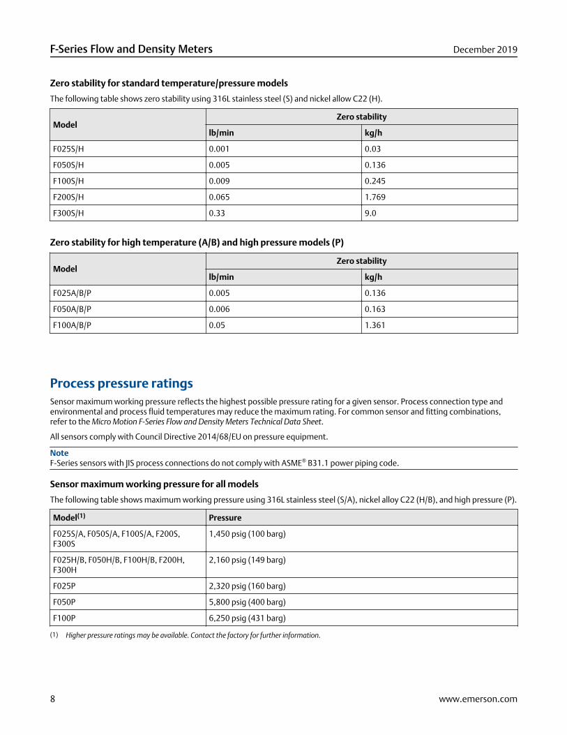
Zero stability for standard temperature/pressure models
The following table shows zero stability using 316L stainless steel (S) and nickel allow C22 (H).
ModelZero stability
lb/min kg/h
F025S/H 0.001 0.03
F050S/H 0.005 0.136
F100S/H 0.009 0.245
F200S/H 0.065 1.769
F300S/H 0.33 9.0
Zero stability for high temperature (A/B) and high pressure models (P)
ModelZero stability
lb/min kg/h
F025A/B/P 0.005 0.136
F050A/B/P 0.006 0.163
F100A/B/P 0.05 1.361
Process pressure ratingsSensor maximum working pressure reflects the highest possible pressure rating for a given sensor. Process connection type andenvironmental and process fluid temperatures may reduce the maximum rating. For common sensor and fitting combinations,refer to the Micro Motion F-Series Flow and Density Meters Technical Data Sheet.
All sensors comply with Council Directive 2014/68/EU on pressure equipment.
NoteF-Series sensors with JIS process connections do not comply with ASME® B31.1 power piping code.
Sensor maximum working pressure for all models
The following table shows maximum working pressure using 316L stainless steel (S/A), nickel alloy C22 (H/B), and high pressure (P).
Model(1) Pressure
F025S/A, F050S/A, F100S/A, F200S,F300S
1,450 psig (100 barg)
F025H/B, F050H/B, F100H/B, F200H,F300H
2,160 psig (149 barg)
F025P 2,320 psig (160 barg)
F050P 5,800 psig (400 barg)
F100P 6,250 psig (431 barg)
(1) Higher pressure ratings may be available. Contact the factory for further information.
F-Series Flow and Density Meters December 2019
8 www.emerson.com
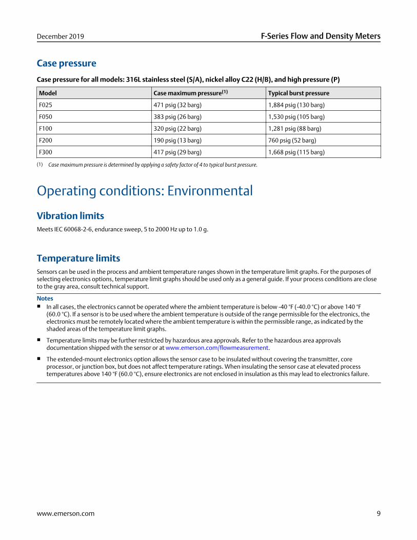
Case pressure
Case pressure for all models: 316L stainless steel (S/A), nickel alloy C22 (H/B), and high pressure (P)
Model Case maximum pressure(1) Typical burst pressure
F025 471 psig (32 barg) 1,884 psig (130 barg)
F050 383 psig (26 barg) 1,530 psig (105 barg)
F100 320 psig (22 barg) 1,281 psig (88 barg)
F200 190 psig (13 barg) 760 psig (52 barg)
F300 417 psig (29 barg) 1,668 psig (115 barg)
(1) Case maximum pressure is determined by applying a safety factor of 4 to typical burst pressure.
Operating conditions: Environmental
Vibration limitsMeets IEC 60068-2-6, endurance sweep, 5 to 2000 Hz up to 1.0 g.
Temperature limitsSensors can be used in the process and ambient temperature ranges shown in the temperature limit graphs. For the purposes ofselecting electronics options, temperature limit graphs should be used only as a general guide. If your process conditions are closeto the gray area, consult technical support.
Notes■ In all cases, the electronics cannot be operated where the ambient temperature is below -40 °F (-40.0 °C) or above 140 °F
(60.0 °C). If a sensor is to be used where the ambient temperature is outside of the range permissible for the electronics, theelectronics must be remotely located where the ambient temperature is within the permissible range, as indicated by theshaded areas of the temperature limit graphs.
■ Temperature limits may be further restricted by hazardous area approvals. Refer to the hazardous area approvalsdocumentation shipped with the sensor or at www.emerson.com/flowmeasurement.
■ The extended-mount electronics option allows the sensor case to be insulated without covering the transmitter, coreprocessor, or junction box, but does not affect temperature ratings. When insulating the sensor case at elevated processtemperatures above 140 °F (60.0 °C), ensure electronics are not enclosed in insulation as this may lead to electronics failure.
December 2019 F-Series Flow and Density Meters
www.emerson.com 9
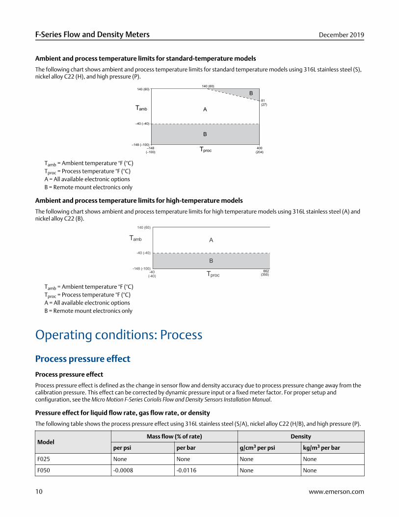
Ambient and process temperature limits for standard-temperature models
The following chart shows ambient and process temperature limits for standard temperature models using 316L stainless steel (S),nickel alloy C22 (H), and high pressure (P).
140 (60)
–40 (–40)
81 (27)
–148 (–100)–148
(–100)400
(204)
140 (60)
A
B
B
Tamb
Tproc
Tamb = Ambient temperature °F (°C)Tproc = Process temperature °F (°C)A = All available electronic optionsB = Remote mount electronics only
Ambient and process temperature limits for high-temperature models
The following chart shows ambient and process temperature limits for high temperature models using 316L stainless steel (A) andnickel alloy C22 (B).
-40 (-40)
-148 (-100)
Tamb
Tproc
A
B
140 (60)
-40(-40)
662(350)
Tamb = Ambient temperature °F (°C)Tproc = Process temperature °F (°C)A = All available electronic optionsB = Remote mount electronics only
Operating conditions: Process
Process pressure effect
Process pressure effect
Process pressure effect is defined as the change in sensor flow and density accuracy due to process pressure change away from thecalibration pressure. This effect can be corrected by dynamic pressure input or a fixed meter factor. For proper setup andconfiguration, see the Micro Motion F-Series Coriolis Flow and Density Sensors Installation Manual.
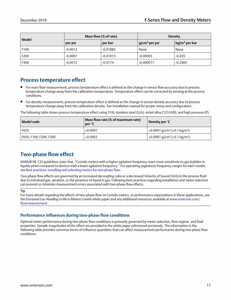
Pressure effect for liquid flow rate, gas flow rate, or density
The following table shows the process pressure effect using 316L stainless steel (S/A), nickel alloy C22 (H/B), and high pressure (P).
ModelMass flow (% of rate) Density
per psi per bar g/cm3 per psi kg/m3 per bar
F025 None None None None
F050 -0.0008 -0.0116 None None
F-Series Flow and Density Meters December 2019
10 www.emerson.com
ModelMass flow (% of rate) Density
per psi per bar g/cm3 per psi kg/m3 per bar
F100 -0.0013 -0.01885 None None
F200 -0.0007 -0.01015 -0.00003 -0.435
F300 -0.0012 -0.0174 -0.000017 -0.2465
Process temperature effect■ For mass flow measurement, process temperature effect is defined as the change in sensor flow accuracy due to process
temperature change away from the calibration temperature. Temperature effect can be corrected by zeroing at the processconditions.
■ For density measurement, process temperature effect is defined as the change in sensor density accuracy due to processtemperature change away from the calibration density. See installation manual for proper setup and configuration.
The following table shows process temperature effect using 316L stainless steel (S/A), nickel alloy C22 (H/B), and high pressure (P).
Model codeMass flow rate (% of maximum rate)per °C
Density per °C
F025 ±0.0007 ±0.0001 g/cm³ (±0.1 kg/m³)
F050, F100, F200, F300 ±0.0002 ±0.0001 g/cm³ (±0.1 kg/m³)
Two-phase flow effectNAMUR NE 132 guidelines state that, “Coriolis meters with a higher agitation frequency react more sensitively to gas bubbles inliquids when compared to devices with a lower agitation frequency.” For operating (agitation) frequency ranges for each model,see Best practices: installing and selecting meters for two-phase flow.
Two-phase flow effects are governed by an increased decoupling ratio or a decreased Velocity of Sound (VoS) in the process fluiddue to entrained gas, aeration, or the presence of liquid in gas. Following best practices regarding installation and meter selectioncan prevent or minimize measurement errors associated with two-phase flow effects.
TipFor more details regarding the effects of two-phase flow on Coriolis meters, or performance expectations in these applications, seethe Entrained Gas Handling in Micro Motion Coriolis white paper and any additional resources available at www.emerson.com/flowmeasurement.
Performance influences during two-phase flow conditionsOptimal meter performance during two-phase flow conditions is primarily governed by meter selection, flow regime, and fluidproperties. Sample magnitudes of the effect are provided in the white paper referenced previously. The information in thefollowing table provides common forms of influence quantities that can affect measurement performance during two-phase flowconditions.
December 2019 F-Series Flow and Density Meters
www.emerson.com 11

Two-phase flow performance influence factors
Type of influence Specific influence on measurement Recommendation
VoS / fluid compressibility Over-reading due to interaction betweenfrequency of the acoustic and drivemodes
Select a meter that operates in an ULTRA-LOW(1) or LOW drive frequency range toavoid VoS effects.
Decoupling Under-reading as a result of bubble orparticle movement with respect to thefluid
Increase fluid viscosity, decrease bubblesize, or use a meter with lower drivefrequency in order to minimizedecoupling.
Signal processing noise Ability to maintain signal accuracy duringhigh noise conditions or rapid processchanges
Select advanced electronics that usehigh-speed mass and density signalprocessing methods for effective noiserejection.
(1) See Operating drive mode frequency range for all models.
Best practices: installing and selecting meters for two-phase flowFlow sensor best practices:
■ Ensure that the meter is sized correctly to maintain a flow rate greater than 5:1 turndown from nominal.
■ Install the meter with the preferred orientation. For orientation based on fluid type, see the Micro Motion F-Series Coriolis Flowand Density Sensors Installation Manual.
■ Select a meter design with the lowest available operating frequency.
Transmitter and electronics best practices:
■ Enable multiphase severity alerts to accurately detect when two-phase flow is present.
■ Select a meter with a real-time clock and historian capabilities to diagnose process events or upsets.
■ Use Advanced Phase Measurement in intermittent high %GVF or %LVF installations where density or volume flow is required.
Operating drive mode frequency range for all models
Reference conditions: water at 14.7 psig (1.014 barg) and 60 °F (16 °C).
ULTRA-LOW (<100 hZ) Preferred solution for installations with two-phase flow conditions
LOW (100 - 150 hZ) Preferred solution for installations with two-phase flow conditions
MID-RANGE (150 - 300 hZ) Suitable in some instances for installations with two-phase flow conditions
HIGH (> 300 hZ) Not recommended for two-phase flow installations
Range Model code
ULTRA-LOW (< 100 Hz) See the Micro Motion ELITE Coriolis Flow and Density MetersProduct Data Sheet
LOW (100-150 Hz) See the Micro Motion ELITE Coriolis Flow and Density MetersProduct Data Sheet
MID-RANGE (150-300 Hz) F025, F050, F100, F200, F300
HIGH (> 300 Hz) None
F-Series Flow and Density Meters December 2019
12 www.emerson.com
Viscosity rangeFor installations with 3 in (DN80) or larger meters, and fluid viscosities greater than 500 centistokes (cSt), consult your MicroMotion sales representative or technical support for guidance on optimizing your configuration. This recommendation is notapplicable for smaller meters or processes with viscosities less than 500 cSt.
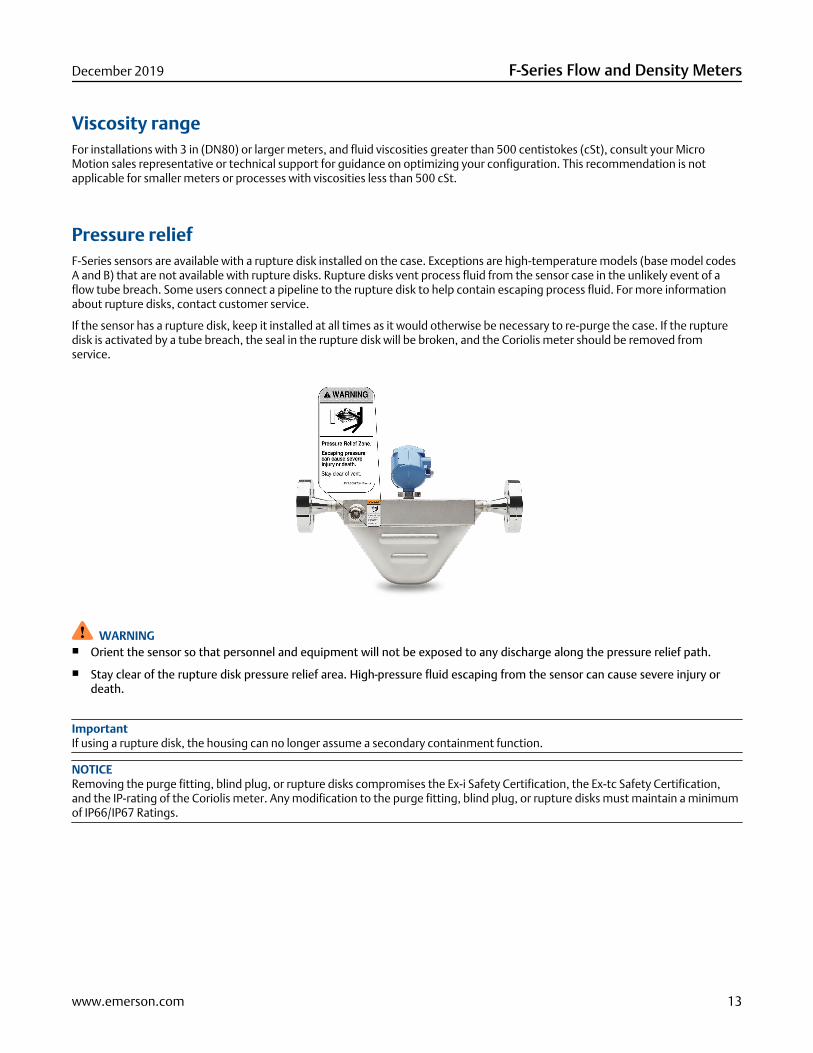
Pressure reliefF-Series sensors are available with a rupture disk installed on the case. Exceptions are high-temperature models (base model codesA and B) that are not available with rupture disks. Rupture disks vent process fluid from the sensor case in the unlikely event of aflow tube breach. Some users connect a pipeline to the rupture disk to help contain escaping process fluid. For more informationabout rupture disks, contact customer service.
If the sensor has a rupture disk, keep it installed at all times as it would otherwise be necessary to re-purge the case. If the rupturedisk is activated by a tube breach, the seal in the rupture disk will be broken, and the Coriolis meter should be removed fromservice.
WARNING■ Orient the sensor so that personnel and equipment will not be exposed to any discharge along the pressure relief path.
■ Stay clear of the rupture disk pressure relief area. High-pressure fluid escaping from the sensor can cause severe injury ordeath.
ImportantIf using a rupture disk, the housing can no longer assume a secondary containment function.
NOTICERemoving the purge fitting, blind plug, or rupture disks compromises the Ex-i Safety Certification, the Ex-tc Safety Certification,and the IP-rating of the Coriolis meter. Any modification to the purge fitting, blind plug, or rupture disks must maintain a minimumof IP66/IP67 Ratings.
December 2019 F-Series Flow and Density Meters
www.emerson.com 13

Hazardous area classifications
Approvals and certifications
Type Approval or certification (typical)
CSA and CSA C-US Ambient temperature:
Ambient temperature: -40 °F (-40.0 °C) to 140 °F (60.0 °C)
Class I, Div. 1, Groups C and D
Class I, Div. 2, Groups A, B, C, and D Class II, Div.1, Groups E, F, and G
ATEX II 1(2) G Ex ib IIB/IIC T6.T1 Ga/Gb
II 2 D Ex ib IIIC T* °C Db IP66/IP67
II 3G Ex nA IIC T1–T4/T5 Gc
II 3D Ex tc IIIC T*°C Dc IP66
IECEx Ex ib IIB/IIC T1–T4/T5/T6 Ga/Gb
Ex ib IIIC T* °C Db
Ex nA IIC T1-T4/T5 Gc
Ex tc IIIC T* °C Dc
NEPSI Ex ib IIB/IIC T1–T6 Gb
Ex ibD 21 T450°C-T85°C Ex nA IIC T1–T6 Gc
DIP A22 T* T1-T6
Ingress ProtectionRating
IP 66 for sensors; IP 66/67 for transmitters
EMC effects Complies with EMC directive 2004/108/EC per EN 61326 Industrial
Complies with NAMUR NE-21 (09.05.2012)
Notes■ Approvals shown are for F-Series meters. Meters with integral electronics may have more restrictive approvals. For transmitter
details, see Micro Motion F-Series Flow and Density Meters Technical Data Sheet.
■ When a meter is ordered with hazardous area approvals, detailed information is shipped along with the product.
■ You can find more information about hazardous approvals, including detailed specifications and temperature graphs for allmeter configurations on the F-Series product page at www.emerson.com/flowmeasurement.
F-Series Flow and Density Meters December 2019
14 www.emerson.com

Industry standards
Type Standard
Weights & Measures forcustody transferapplications
■ MID OIML R117
■ National Type Evaluation Program (NTEP)
■ Measurement Canada
■ INMETRO Brazil
Industry standards andcommercial approvals
■ NAMUR: NE132 (burst pressure, sensor flange to flange length), NE131
■ Pressure Equipment Directive (PED)
■ Canadian Registration Number (CRN)
■ Dual Seal
■ ASME B31.1 power piping code and ASME B31.3 process piping code
■ SIL2 and SIL3 safety certifications
NoteSome models do not meet all of the listed standards. Contact a sales representative for more information.
Marine approval classifications
For models F025S, F050S, F100S/P, F200S and F300S.
Marine approval Country
Lloyd’s Register ENV1, ENV2, ENV3, ENV5 United Kingdom
Det Norske Veritas- Germanischer Lloyd Norway-Germany
Bureau Veritas France
American Bureau of Shipping USA
Nippon Kaiji Kyokai Japan
December 2019 F-Series Flow and Density Meters
www.emerson.com 15
ConnectivityF-Series sensors are highly customizable to provide a configuration that is tailor-fit to specific applications.
For help determining which Micro Motion products are right for your application, see the Micro Motion Technical Overview andSpecification Summary and other resources at www.emerson.com/flowmeasurement.
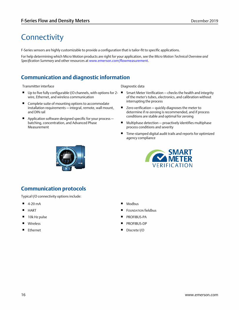
Communication and diagnostic information
Transmitter interface Diagnostic data
■ Up to five fully configurable I/O channels, with options for 2-wire, Ethernet, and wireless communication
■ Complete suite of mounting options to accommodateinstallation requirements — integral, remote, wall mount,and DIN rail
■ Application software designed specific for your process —batching, concentration, and Advanced PhaseMeasurement
■ Smart Meter Verification — checks the health and integrityof the meter's tubes, electronics, and calibration withoutinterrupting the process
■ Zero verification — quickly diagnoses the meter todetermine if re-zeroing is recommended, and if processconditions are stable and optimal for zeroing
■ Multiphase detection — proactively identifies multiphaseprocess conditions and severity
■ Time-stamped digital audit trails and reports for optimizedagency compliance
Communication protocolsTypical I/O connectivity options include:
■ 4-20 mA
■ HART
■ 10k Hz pulse
■ Wireless
■ Ethernet
■ Modbus
■ FOUNDATION fieldbus
■ PROFIBUS-PA
■ PROFIBUS-DP
■ Discrete I/O
F-Series Flow and Density Meters December 2019
16 www.emerson.com

Transmitter compatibility and primary attributesFor a complete list of all transmitter configurations and options, see the transmitter product data sheets and other resourcesavailable at www.emerson.com/flowmeasurement.
ModelTransmitter
1500/2500 1700/2700 2400S 3000 series FMT 4200 5700
Flow meters
F025, F050,F100
• • • • • • •
F200, F300 • • • • • •
Power
AC • • • •
DC • • • • • •
Loop powered(2-wire)
•
Diagnostics
SMV basic(included)
• • • • • •
SMV Pro • • • • • •
Real timeclock
• •
Onboard datahistorian
• •
Local operator interface
2-line display • •
Graphicaldisplay
• • •
Certifications and approvals
SIS certified • • •
Custodytransfer
• • •
December 2019 F-Series Flow and Density Meters
www.emerson.com 17
Physical specifications
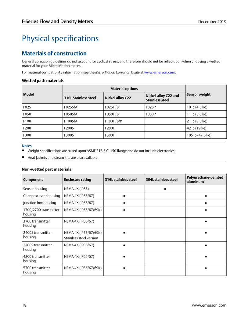
Materials of constructionGeneral corrosion guidelines do not account for cyclical stress, and therefore should not be relied upon when choosing a wettedmaterial for your Micro Motion meter.
For material compatibility information, see the Micro Motion Corrosion Guide at www.emerson.com.
Wetted path materials
Model
Material options
Sensor weight316L Stainless steel Nickel alloy C22
Nickel alloy C22 andStainless steel
F025 F025S/A F025H/B F025P 10 lb (4.5 kg)
F050 F050S/A F050H/B F050P 11 lb (5.0 kg)
F100 F100S/A F100H/B/P 21 lb (9.5 kg)
F200 F200S F200H 42 lb (19 kg)
F300 F300S F300H 105 lb (47.6 kg)
Notes■ Weight specifications are based upon ASME B16.5 CL150 flange and do not include electronics.
■ Heat jackets and steam kits are also available.
Non-wetted part materials
Component Enclosure rating 316L stainless steel 304L stainless steelPolyurethane-paintedaluminum
Sensor housing NEMA 4X (IP66) ●
Core processor housing NEMA 4X (IP66/67) ● ●
Junction box housing NEMA 4X (IP66/67) ● ●
1700/2700 transmitterhousing
NEMA 4X (IP66/67/69K) ● ●
3700 transmitterhousing
NEMA 4X (IP66/67) ●
2400S transmitterhousing
NEMA 4X (IP66/67/69K)
Stainless steel version
● ●
2200S transmitterhousing
NEMA 4X (IP66/67) ● ●
4200 transmitterhousing
NEMA 4X (IP66/67) ● ●
5700 transmitterhousing
NEMA 4X (IP66/67/69K) ● ●
F-Series Flow and Density Meters December 2019
18 www.emerson.com

Flanges
Sensor type Flange types
Stainless steel 316L ■ ASME B16.5 weld neck flange raised face (up to CL600)
■ EN 1092-1 weld neck flange form B1, B2, D (up to PN100), and F
■ JIS B2220 weld neck raised face (up to 40K)
■ NAMUR NE 132 compliant flange options for standardized face-to-face dimensions
■ VCO, VCR swagelok compatible fitting
■ Hygienic Tri-Clamp® compatible
Nickel alloy C22 ■ ASME B16.5 lap joint flange (up to CL900/1500)
■ EN 1092-1 lap joint flange form B1 (up to PN40)
■ JIS B2220 lap joint flange (up to 10K)
■ Hygienic Tri-Clamp compatible
High pressure ■ ASME B16.5 weld neck flange (up to CL2500)
■ VCO swagelok compatible fitting
■ EN 1092-1 weld neck flange type B2, D (up to PN160)
Notes■ For flange compatibility, see the Online Store Sizing and Selection Tool at www.emerson.com/flowmeasurement.
■ For more information on available NAMUR NE 132 compliant flange options, see the Micro Motion F-Series Flow and DensityMeters Technical Data Sheet.
DimensionsThese dimensional drawings provide a basic guideline for sizing and planning.
For Face-to-Face (Dim. A, below) dimensions for all F-Series meters with each available process connection, see the Micro Motion F-Series Flow and Density Meters Technical Data Sheet.
For detailed dimensional drawings, go to www.emerson.com/flowmeasurement.
Notes■ All dimensions are ±0.13 in (±3 mm).
■ Representative of a sensor model fitted with ASME B16.5 CL150 flange, and 2400 transmitter
December 2019 F-Series Flow and Density Meters
www.emerson.com 19
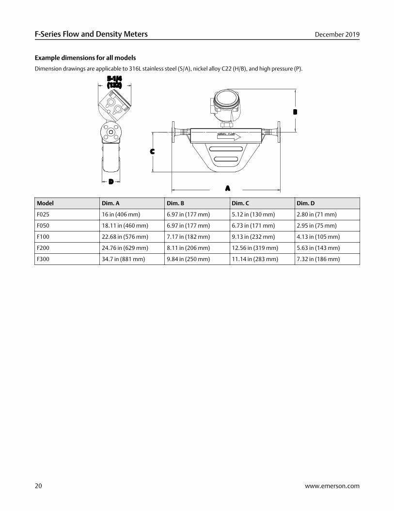
Example dimensions for all models
Dimension drawings are applicable to 316L stainless steel (S/A), nickel alloy C22 (H/B), and high pressure (P).
A
5-1/4(132)
B
C
D
Model Dim. A Dim. B Dim. C Dim. D
F025 16 in (406 mm) 6.97 in (177 mm) 5.12 in (130 mm) 2.80 in (71 mm)
F050 18.11 in (460 mm) 6.97 in (177 mm) 6.73 in (171 mm) 2.95 in (75 mm)
F100 22.68 in (576 mm) 7.17 in (182 mm) 9.13 in (232 mm) 4.13 in (105 mm)
F200 24.76 in (629 mm) 8.11 in (206 mm) 12.56 in (319 mm) 5.63 in (143 mm)
F300 34.7 in (881 mm) 9.84 in (250 mm) 11.14 in (283 mm) 7.32 in (186 mm)
F-Series Flow and Density Meters December 2019
20 www.emerson.com
Ordering informationUse this section to select the correct ordering codes for your configuration.
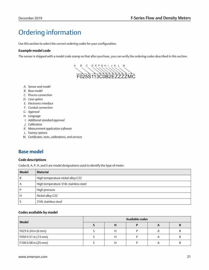
Example model code
The sensor is shipped with a model code stamp so that after purchase, you can verify the ordering codes described in this section.
F025S113C0B2EZZZZMC
A B C D E F G H I J K L M
A. Sensor and modelB. Base modelC. Process connectionD. Case optionE. Electronics interfaceF. Conduit connection
G. ApprovalH. Language
I. Additional standard approvalJ. Calibration
K. Measurement application softwareL. Factory options
M. Certificates, tests, calibrations, and services
Base model
Code descriptions
Codes B, A, P, H, and S are model designations used to identify the type of meter.
Model Material
B High temperature nickel alloy C22
A High temperature 316L stainless steel
P High pressure
H Nickel alloy C22
S 316L stainless steel
Codes available by model
ModelAvailable codes
S H P A B
F025 0.24 in (6 mm) S H P A B
F050 0.51 in (13 mm) S H P A B
F100 0.98 in (25 mm) S H P A B
December 2019 F-Series Flow and Density Meters
www.emerson.com 21

ModelAvailable codes
S H P A B
F200 1.97 in (50 mm) S H
F300 3.15 in (80 mm) S H
Process connections
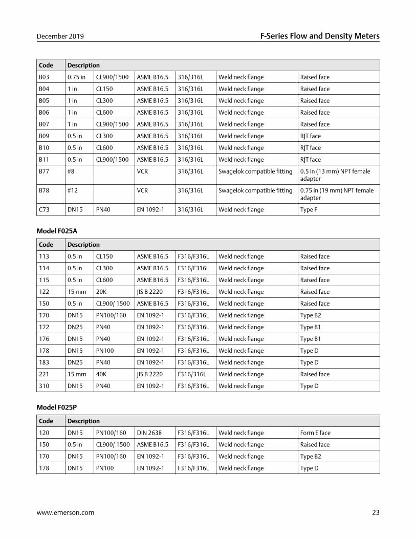
Model F025S
Code Description
113 0.5 in CL150 ASME B16.5 F316/F316L Weld neck flange Raised face
114 0.5 in CL300 ASME B16.5 F316/F316L Weld neck flange Raised face
115 0.5 in CL600 ASME B16.5 F316/F316L Weld neck flange Raised face
116 DN15 PN40 DIN 2635 F316/F316L Weld neck flange Form C face
120 DN15 PN100/160 DIN 2638 F316/F316L Weld neck flange Form E face
121 0.5 in Tri-Clampcompatible
316L Hygienic fitting
122 15 mm 20K JIS B 2220 F316/316L Weld neck flange Raised face
150 0.5 in CL900/1500 ASME B16.5 F316/316L Weld neck flange Raised face
170 DN15 PN100/160 EN 1092-1 F316/F316L Weld neck flange Type B2
172 DN25 PN40 EN 1092-1 F316/F316L Weld neck flange Type B1
176 DN15 PN40 EN 1092-1 F316/F316L Weld neck flange Type B1
178 DN15 PN100 EN 1092-1 F316/F316L Weld neck flange Type D
183 DN25 PN40 EN 1092-1 F316/F316L Weld neck flange Type D
221 15 mm 40K JIS B 2220 F316/316L Weld neck flange Raised face
222 DN15 DIN11851 316/316L Hygienic coupling
310 DN15 PN40 EN 1092-1 F316/F316L Weld neck flange Type D
319 #8 VCO 316/316L Swagelok compatible fitting 0.5 in (13 mm) NPT femaleadapter
A94 0.5 in CL150 ASME B16.5 316/316L Weld neck flange Raised face 63-125 RA facefinish
A95 0.5 in CL300 ASME B16.5 316/316L Weld neck flange Raised face 63-125 RA facefinish
A96 0.5 in CL600 ASME B16.5 316/316L Weld neck flange Raised face 63-125 RA facefinish
A97 0.5 in CL900/1500 ASME B16.5 316/316L Weld neck flange Raised face 63-125 RA facefinish
A99 0.75 in CL150 ASME B16.5 316/316L Weld neck flange Raised face
B01 0.75 in CL300 ASME B16.5 316/316L Weld neck flange Raised face
B02 0.75 in CL600 ASME B16.5 316/316L Weld neck flange Raised face
F-Series Flow and Density Meters December 2019
22 www.emerson.com
Code Description
B03 0.75 in CL900/1500 ASME B16.5 316/316L Weld neck flange Raised face
B04 1 in CL150 ASME B16.5 316/316L Weld neck flange Raised face
B05 1 in CL300 ASME B16.5 316/316L Weld neck flange Raised face
B06 1 in CL600 ASME B16.5 316/316L Weld neck flange Raised face
B07 1 in CL900/1500 ASME B16.5 316/316L Weld neck flange Raised face
B09 0.5 in CL300 ASME B16.5 316/316L Weld neck flange RJT face
B10 0.5 in CL600 ASME B16.5 316/316L Weld neck flange RJT face
B11 0.5 in CL900/1500 ASME B16.5 316/316L Weld neck flange RJT face
B77 #8 VCR 316/316L Swagelok compatible fitting 0.5 in (13 mm) NPT femaleadapter
B78 #12 VCR 316/316L Swagelok compatible fitting 0.75 in (19 mm) NPT femaleadapter
C73 DN15 PN40 EN 1092-1 316/316L Weld neck flange Type F
Model F025A
Code Description
113 0.5 in CL150 ASME B16.5 F316/F316L Weld neck flange Raised face
114 0.5 in CL300 ASME B16.5 F316/F316L Weld neck flange Raised face
115 0.5 in CL600 ASME B16.5 F316/F316L Weld neck flange Raised face
122 15 mm 20K JIS B 2220 F316/F316L Weld neck flange Raised face
150 0.5 in CL900/ 1500 ASME B16.5 F316/F316L Weld neck flange Raised face
170 DN15 PN100/160 EN 1092-1 F316/F316L Weld neck flange Type B2
172 DN25 PN40 EN 1092-1 F316/F316L Weld neck flange Type B1
176 DN15 PN40 EN 1092-1 F316/F316L Weld neck flange Type B1
178 DN15 PN100 EN 1092-1 F316/F316L Weld neck flange Type D
183 DN25 PN40 EN 1092-1 F316/F316L Weld neck flange Type D
221 15 mm 40K JIS B 2220 F316/316L Weld neck flange Raised face
310 DN15 PN40 EN 1092-1 F316/F316L Weld neck flange Type D
Model F025P
Code Description
120 DN15 PN100/160 DIN 2638 F316/F316L Weld neck flange Form E face
150 0.5 in CL900/ 1500 ASME B16.5 F316/F316L Weld neck flange Raised face
170 DN15 PN100/160 EN 1092-1 F316/F316L Weld neck flange Type B2
178 DN15 PN100 EN 1092-1 F316/F316L Weld neck flange Type D
December 2019 F-Series Flow and Density Meters
www.emerson.com 23

Code Description
180 DN25 PN100 EN 1092-1 F316/F316L Weld neck flange Type B2
319 #8 VCO 316/316L Swagelok compatible fitting 0.5 in (13 mm) NPT femaleadapter
Models F025H and F025B
Code Description
517 0.5 in CL600 ASME B16.5 F304/F304L Lap joint flange N06022 stub
520 0.5 in CL150 ASME B16.5 F304/F304L Lap joint flange N06022 stub
521 0.5 in CL300 ASME B16.5 F304/F304L Lap joint flange N06022 stub
522 15 mm 10K JIS B 2220 F304/F304L Lap joint flange N06022 stub
524 DN15 PN40 EN 1092-1 F304/F304L Lap joint flange Type B1, N06022 stub
Model F050S
Code Description
113 0.5 in CL150 ASME B16.5 F316/F316L Weld neck flange Raised face
114 0.5 in CL300 ASME B16.5 F316/F316L Weld neck flange Raised face
115 0.5 in CL600 ASME B16.5 F316/F316L Weld neck flange Raised face
116 DN15 PN40 DIN 2635 F316/F316L Weld neck flange Form C face
120 DN15 PN100/160 DIN 2638 F316/F316L Weld neck flange Form E face
122 15 mm 20K JIS B 2220 F316/316L Weld neck flange Raised face
131 DN25 PN40 DIN 2635 F316/F316L Weld neck flange Form C face
150 0.5 in CL900/1500 ASME B16.5 F316/F316L Weld neck flange Raised face
170 DN15 PN100/160 EN 1092-1 F316/F316L Weld neck flange Type B2
172 DN25 PN40 EN 1092-1 F316/F316L Weld neck flange Type B1
176 DN15 PN40 EN 1092-1 F316/F316L Weld neck flange Type B1
178 DN15 PN100 EN 1092-1 F316/F316L Weld neck flange Type D
183 DN25 PN40 EN 1092-1 F316/F316L Weld neck flange Type D
221 15 mm 40K JIS B 2220 F316/316L Weld neck flange Raised face
222 DN15 DIN11851 316/316L Hygienic coupling
239 #12 VCO 316/316L Swagelok compatible fitting 0.75 in (19 mm) NPT femaleadapter
310 DN15 PN40 EN 1092-1 F316/F316L Weld neck flange Type D
322 0.75 in Tri-Clampcompatible
316L Hygienic fitting
A94 0.5 in CL150 ASME B16.5 316/316L Weld neck flange Raised face 63-125 RA facefinish
A95 0.5 in CL300 ASME B16.5 316/316L Weld neck flange Raised face 63-125 RA facefinish
F-Series Flow and Density Meters December 2019
24 www.emerson.com

Code Description
A96 0.5 in CL600 ASME B16.5 316/316L Weld neck flange Raised face 63-125 RA facefinish
A97 0.5 in CL900 ASME B16.5 316/316L Weld neck flange Raised face 63-125 RA facefinish
A99 0.75 in CL150 ASME B16.5 316/316L Weld neck flange Raised face
B01 0.75 in CL300 ASME B16.5 316/316L Weld neck flange Raised face
B02 0.75 in CL600 ASME B16.5 316/316L Weld neck flange Raised face
B03 0.75 in CL900/1500 ASME B16.5 316/316L Weld neck flange Raised face
B04 1 in CL150 ASME B16.5 316/316L Weld neck flange Raised face
B05 1 in CL300 ASME B16.5 316/316L Weld neck flange Raised face
B06 1 in CL600 ASME B16.5 316/316L Weld neck flange Raised face
B07 1in CL900/1500 ASME B16.5 316/316L Weld neck flange Raised face
B09 0.5 in CL300 ASME B16.5 316/316L Weld neck flange RTJ face
B10 0.5 in CL600 ASME B16.5 316/316L Weld neck flange RTJ face
B11 0.5 in CL900/1500 ASME B16.5 316/316L Weld neck flange RTJ face
B77 #8 VCR 316/316L Swagelok compatibile fitting 0.5 in (13 mm) 316 NPTfemale adapter
B78 #12 VCR 316/316L Swagelok compatibile fitting 0.75 in (19 mm) 316 NPTfemale adapter
C73 DN15 PN40 EN 1092-1 316/316L Weld neck flange Type F
Model F050A
Code Description
113 0.5 in CL150 ASME B16.5 F316/F316L Weld neck flange Raised face
114 0.5 in CL300 ASME B16.5 F316/F316L Weld neck flange Raised face
115 0.5 in CL600 ASME B16.5 F316/F316L Weld neck flange Raised face
122 15 mm 20K JIS B 2220 F316/F316L Weld neck flange Raised face
150 0.5 in CL900/ 1500 ASME B16.5 F316/F316L Weld neck flange Raised face
170 DN15 PN100/160 EN 1092-1 F316/F316L Weld neck flange Type B2
172 DN25 PN40 EN 1092-1 F316/F316L Weld neck flange Type B1
176 DN15 PN40 EN 1092-1 F316/F316L Weld neck flange Type B1
178 DN15 PN100 EN 1092-1 F316/F316L Weld neck flange Type D
183 DN25 PN40 EN 1092-1 F316/F316L Weld neck flange Type D
221 15 mm 40K JIS B 2220 F316/316L Weld neck flange Raised face
310 DN15 PN40 EN 1092-1 F316/F316L Weld neck flange Type D
December 2019 F-Series Flow and Density Meters
www.emerson.com 25

Model F050P
Code Description
113 0.5 in CL150 ASME B16.5 F316/F316L Weld neck flange Raised face
114 0.5 in CL300 ASME B16.5 F316/F316L Weld neck flange Raised face
115 0.5 in CL600 ASME B16.5 F316/F316L Weld neck flange Raised face
116 DN15 PN40 DIN 2635 F316/F316L Weld neck flange Form C face
120 DN15 PN100/160 DIN 2638 F316/F316L Weld neck flange Form E face
122 15 mm 20K JIS B 2220 F316/F316L Weld neck flange Raised face
131 DN25 PN40 DIN 2635 F316/F316L Weld neck flange Form C face
150 0.5 in CL900/ 1500 ASME B16.5 F316/F316L Weld neck flange Raised face
170 DN15 PN100/160 EN 1092-1 F316/F316L Weld neck flange Type B2
178 DN15 PN100 EN 1092-1 F316/F316L Weld neck flange Type D
180 DN25 PN100 EN 1092-1 F316/F316L Weld neck flange Type B2
222 DN15 DIN11851 316/316L Hygienic coupling
239 #12 VCO 316/316L Swagelok compatible fitting 0.75 in (19 mm) NPT femaleadapter
322 0.75 in Tri-Clampcompatible
316L Hygienic fitting
Models F050H and F050B
Code Description
517 0.5 in CL600 ASME B16.5 F304/F304L Lap joint flange N06022 stub
520 0.5 in CL150 ASME B16.5 F304/F304L Lap joint flange N06022 stub
521 0.5 in CL300 ASME B16.5 F304/F304L Lap joint flange N06022 stub
522 15 mm 10K JIS B 2220 F304/F304L Lap joint flange N06022 stub
524 DN15 PN40 EN 1092-1 F304/F304L Lap joint flange Type B1, N06022 stub
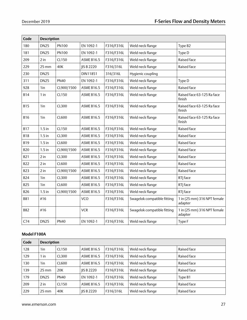
Model F100S
Code Description
128 1in CL150 ASME B16.5 F316/F316L Weld neck flange Raised face
129 1 in CL300 ASME B16.5 F316/F316L Weld neck flange Raised face
130 1in CL600 ASME B16.5 F316/F316L Weld neck flange Raised face
131 DN25 PN40 DIN 2635 F316/F316L Weld neck flange Form C face
137 DN25 PN100/160 DIN 2638 F316/F316L Weld neck flange Form E face
138 1in Tri-Clampcompatible
316L Hygienic fitting
139 25 mm 20K JIS B 2220 F316/F316L Weld neck flange Raised face
179 DN25 PN40 EN 1092-1 F316/F316L Weld neck flange Type B1
F-Series Flow and Density Meters December 2019
26 www.emerson.com
Code Description
180 DN25 PN100 EN 1092-1 F316/F316L Weld neck flange Type B2
181 DN25 PN100 EN 1092-1 F316/F316L Weld neck flange Type D
209 2 in CL150 ASME B16.5 F316/F316L Weld neck flange Raised face
229 25 mm 40K JIS B 2220 F316/316L Weld neck flange Raised face
230 DN25 DIN11851 316/316L Hygienic coupling
311 DN25 PN40 EN 1092-1 F316/F316L Weld neck flange Type D
928 1in CL900/1500 ASME B16.5 F316/F316L Weld neck flange Raised face
B14 1 in CL150 ASME B16.5 F316/F316L Weld neck flange Raised face 63-125 Ra facefinish
B15 1in CL300 ASME B16.5 F316/F316L Weld neck flange Raised face 63-125 Ra facefinish
B16 1in CL600 ASME B16.5 F316/F316L Weld neck flange Raised face 63-125 Ra facefinish
B17 1.5 in CL150 ASME B16.5 F316/F316L Weld neck flange Raised face
B18 1.5 in CL300 ASME B16.5 F316/F316L Weld neck flange Raised face
B19 1.5 in CL600 ASME B16.5 F316/F316L Weld neck flange Raised face
B20 1.5 in CL900/1500 ASME B16.5 F316/F316L Weld neck flange Raised face
B21 2 in CL300 ASME B16.5 F316/F316L Weld neck flange Raised face
B22 2 in CL600 ASME B16.5 F316/F316L Weld neck flange Raised face
B23 2 in CL900/1500 ASME B16.5 F316/F316L Weld neck flange Raised face
B24 1in CL300 ASME B16.5 F316/F316L Weld neck flange RTJ face
B25 1in CL600 ASME B16.5 F316/F316L Weld neck flange RTJ face
B26 1.5 in CL900/1500 ASME B16.5 F316/F316L Weld neck flange RTJ face
B81 #16 VCO F316/F316L Swagelok compatible fitting 1 in (25 mm) 316 NPT femaleadapter
B82 #16 VCR F316/F316L Swagelok compatible fitting 1 in (25 mm) 316 NPT femaleadapter
C74 DN25 PN40 EN 1092-1 F316/F316L Weld neck flange Type F
Model F100A
Code Description
128 1in CL150 ASME B16.5 F316/F316L Weld neck flange Raised face
129 1 in CL300 ASME B16.5 F316/F316L Weld neck flange Raised face
130 1in CL600 ASME B16.5 F316/F316L Weld neck flange Raised face
139 25 mm 20K JIS B 2220 F316/F316L Weld neck flange Raised face
179 DN25 PN40 EN 1092-1 F316/F316L Weld neck flange Type B1
209 2 in CL150 ASME B16.5 F316/F316L Weld neck flange Raised face
229 25 mm 40K JIS B 2220 F316/316L Weld neck flange Raised face
December 2019 F-Series Flow and Density Meters
www.emerson.com 27

Code Description
311 DN25 PN40 EN 1092-1 F316/F316L Weld neck flange Type D
928 1in CL900 ASME B16.5 F316/F316L Weld neck flange Raised face
Models F100H and F100B
Code Description
530 1 in CL150 ASME B16.5 F304/F304L Lap joint flange N06022 stub
531 1 in CL300 ASME B16.5 F304/F304L Lap joint flange N06022 stub
532 25 mm 10K JIS B 2220 F304/F304L Lap joint flange N06022 stub
534 DN25 PN40 EN 1092-1 F304/F304L Lap joint flange Type B1, N06022 stub
535 1 in CL600 ASME B16.5 F304/F304L Lap joint flange N06022 stub
Model F100P
Code Description
C55 1 in CL2500 ASME B16.5 Nickel alloyC22
Weld neck flange RTJ
C56 1.5 in CL2500 ASME B16.5 Nickel alloyC22
Weld neck flange RTJ
C57 1 in CL2500 (360bar)
ASME B16.5 F316/F316L Weld neck flange RTJ
C58 1.5 in CL2500(360bar)
ASME B16.5 F316/F316L Weld neck flange RTJ
C64 1 in CL2500 ASME B16.5 F316/F316L Weld neck flange RTJ
C65 1.5 in CL2500 ASME B16.5 F316/F316L Weld neck flange RTJ
Model F200S
Code Description
312 DN40 PN40 EN 1092-1 F316/F316L Weld neck flange Type D
316 DN50 PN40 EN 1092-1 F316/F316L Weld neck flange Type D
341 1.5 in
inch
CL150 ASME B16.5 F316/F316L Weld neck flange Raised face
342 1.5 in CL300 ASME B16.5 F316/F316L Weld neck flange Raised face
343 1.5 in CL600 ASME B16.5 F316/F316L Weld neck flange Raised face
351 1.5 in Tri-Clampcompatible
316L Hygienic fitting
352 2 in Tri-Clampcompatible
316L Hygienic fitting
353 DN40 DIN11851 316/316L Hygienic coupling
363 DN40 PN100 EN 1092-1 F316/F316L Weld neck flange Type B2
F-Series Flow and Density Meters December 2019
28 www.emerson.com

Code Description
365 DN50 PN100 EN 1092-1 F316/F316L Weld neck flange Type B2
366 DN40 PN100 EN 1092-1 F316/F316L Weld neck flange Type D
367 DN50 PN100 EN 1092-1 F316/F316L Weld neck flange Type D
368 DN40 PN40 EN 1092-1 F316/F316L Weld neck flange Type B1
369 DN50 PN40 EN 1092-1 F316/F316L Weld neck flange Type B1
378 DN50 PN100 DIN 2637 F316/F316L Weld neck flange Form E face
381 DN40 PN40 DIN 2635 F316/F316L Weld neck flange Form C face
382 DN50 PN40 DIN 2635 F316/F316L Weld neck flange Form C face
385 40 mm 10K JIS B 2220 F316/F316L Weld neck flange Raised face
386 50 mm 10K JIS B 2220 F316/316L Weld neck flange Raised face
387 40 mm 20K JIS B 2220 F316/F316L Weld neck flange Raised face
388 50 mm 20K JIS B 2220 F316/316L Weld neck flange Raised face
418 2 in CL150 ASME B16.5 F316/F316L Weld neck flange Raised face
419 2 in CL300 ASME B16.5 F316/F316L Weld neck flange Raised face
420 2 in CL600 ASME B16.5 F316/F316L Weld neck flange Raised face
A31 1.5 in CL900/1500 ASME B16.5 F316/F316L Weld neck flange Raised face
A32 1.5 in CL150 ASME B16.5 F316/F316L Weld neck flange Raised face 63-125 Ra facefinish
A33 1.5 in CL300 ASME B16.5 F316/F316L Weld neck flange Raised face 63-125 Ra facefinish
A34 1.5 in CL600 ASME B16.5 F316/F316L Weld neck flange Raised face 63-125 Ra facefinish
A35 2 in CL900/1500 ASME B16.5 F316/F316L Weld neck flange Raised face
A36 3 in CL150 ASME B16.5 F316/F316L Weld neck flange Raised face
A37 3 in CL300 ASME B16.5 F316/F316L Weld neck flange Raised face
A38 3 in CL600 ASME B16.5 F316/F316L Weld neck flange Raised face
A39 2 in CL150 ASME B16.5 F316/F316L Weld neck flange Raised face 63-125 Ra facefinish
A40 2 in CL300 ASME B16.5 F316/F316L Weld neck flange Raised face 63-125 Ra facefinish
A41 2 in CL600 ASME B16.5 F316/F316L Weld neck flange Raised face 63-125 Ra facefinish
A42 2 in CL150 ASME B16.5 F316/F316L Weld neck flange RTJ face
A43 2 in CL300 ASME B16.5 F316/F316L Weld neck flange RTJ face
A44 2 in CL600 ASME B16.5 F316/F316L Weld neck flange RTJ face
A45 2 in CL900/1500 ASME B16.5 F316/F316L Weld neck flange RTJ face
B55 2 in CL600 ASME B16.5 A105 CarbonSteel
Lap joint flange 316/316L stub
December 2019 F-Series Flow and Density Meters
www.emerson.com 29
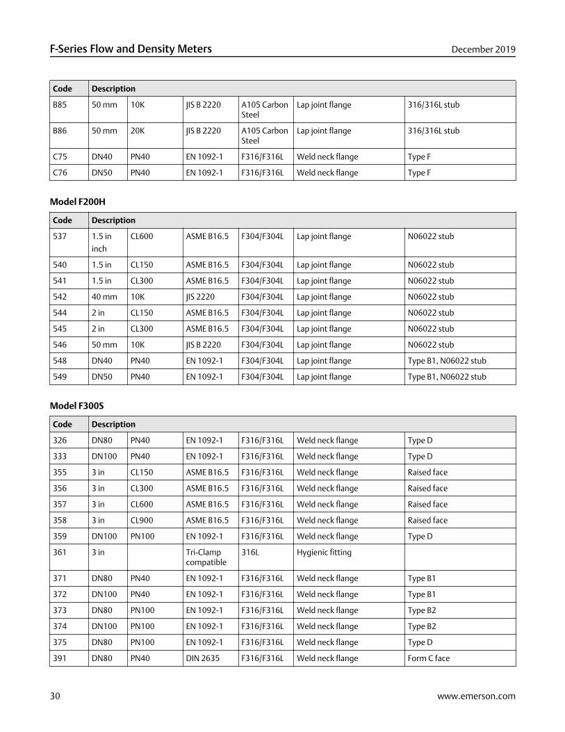
Code Description
B85 50 mm 10K JIS B 2220 A105 CarbonSteel
Lap joint flange 316/316L stub
B86 50 mm 20K JIS B 2220 A105 CarbonSteel
Lap joint flange 316/316L stub
C75 DN40 PN40 EN 1092-1 F316/F316L Weld neck flange Type F
C76 DN50 PN40 EN 1092-1 F316/F316L Weld neck flange Type F
Model F200H
Code Description
537 1.5 in
inch
CL600 ASME B16.5 F304/F304L Lap joint flange N06022 stub
540 1.5 in CL150 ASME B16.5 F304/F304L Lap joint flange N06022 stub
541 1.5 in CL300 ASME B16.5 F304/F304L Lap joint flange N06022 stub
542 40 mm 10K JIS 2220 F304/F304L Lap joint flange N06022 stub
544 2 in CL150 ASME B16.5 F304/F304L Lap joint flange N06022 stub
545 2 in CL300 ASME B16.5 F304/F304L Lap joint flange N06022 stub
546 50 mm 10K JIS B 2220 F304/F304L Lap joint flange N06022 stub
548 DN40 PN40 EN 1092-1 F304/F304L Lap joint flange Type B1, N06022 stub
549 DN50 PN40 EN 1092-1 F304/F304L Lap joint flange Type B1, N06022 stub
Model F300S
Code Description
326 DN80 PN40 EN 1092-1 F316/F316L Weld neck flange Type D
333 DN100 PN40 EN 1092-1 F316/F316L Weld neck flange Type D
355 3 in CL150 ASME B16.5 F316/F316L Weld neck flange Raised face
356 3 in CL300 ASME B16.5 F316/F316L Weld neck flange Raised face
357 3 in CL600 ASME B16.5 F316/F316L Weld neck flange Raised face
358 3 in CL900 ASME B16.5 F316/F316L Weld neck flange Raised face
359 DN100 PN100 EN 1092-1 F316/F316L Weld neck flange Type D
361 3 in Tri-Clampcompatible
316L Hygienic fitting
371 DN80 PN40 EN 1092-1 F316/F316L Weld neck flange Type B1
372 DN100 PN40 EN 1092-1 F316/F316L Weld neck flange Type B1
373 DN80 PN100 EN 1092-1 F316/F316L Weld neck flange Type B2
374 DN100 PN100 EN 1092-1 F316/F316L Weld neck flange Type B2
375 DN80 PN100 EN 1092-1 F316/F316L Weld neck flange Type D
391 DN80 PN40 DIN 2635 F316/F316L Weld neck flange Form C face
F-Series Flow and Density Meters December 2019
30 www.emerson.com

Code Description
392 DN100 PN40 DIN 2635 F316/F316L Weld neck flange Form C face
393 DN80 PN40 DIN 2635 F316/F316L Weld neck flange Form N grooved face
394 DN100 PN40 DIN 2635 F316/F316L Weld neck flange Form N grooved face
395 DN80 PN100 DIN 2637 F316/F316L Weld neck flange Form E face
396 DN100 PN100 DIN 2637 F316/F316L Weld neck flange Form E face
397 DN80 PN100 DIN 2637 F316/F316L Weld neck flange Form N grooved face
398 DN100 PN100 DIN 2637 F316/F316L Weld neck flange Form N grooved face
400 80 mm 10K JIS B 2220 F316/F316L Weld neck flange Raised face
401 100 mm 10K JIS B 2220 F316/F316L Weld neck flange Raised face
402 80 mm 20K JIS B 2220 F316/F316L Weld neck flange Raised face
410 3 in Groovedcoupling
316L Hygienic coupling
425 4 in CL150 ASME B16.5 F316/F316L Weld neck flange Raised face
426 4 in CL300 ASME B16.5 F316/F316L Weld neck flange Raised face
427 4 in CL600 ASME B16.5 F316/F316L Weld neck flange Raised face
428 4 in CL900 ASME B16.5 F316/F316L Weld neck flange Raised face
A47 3 in CL150 ASME B16.5 F316/F316L Weld neck flange Raised face 63-125 Ra facefinish
A48 3 in CL300 ASME B16.5 F316/F316L Weld neck flange Raised face 63-125 Ra facefinish
A49 3 in CL600 ASME B16.5 F316/F316L Weld neck flange Raised face 63-125 Ra facefinish
A50 3 in CL900 ASME B16.5 F316/F316L Weld neck flange Raised face 63-125 Ra facefinish
A52 4 in CL600 ASME B16.5 F316/F316L Weld neck flange Raised face 63-125 Ra facefinish
A53 4 in CL900 ASME B16.5 F316/F316L Weld neck flange Raised face 63-125 Ra facefinish
A54 3 in CL150 ASME B16.5 F316/F316L Weld neck flange RTJ face
A55 3 in CL300 ASME B16.5 F316/F316L Weld neck flange RTJ face
A56 3 in CL600 ASME B16.5 F316/F316L Weld neck flange RTJ face
A57 3 in CL900 ASME B16.5 F316/F316L Weld neck flange RTJ face
A58 4 in CL150 ASME B16.5 F316/F316L Weld neck flange RTJ face
A59 4 in CL300 ASME B16.5 F316/F316L Weld neck flange RTJ face
A60 4 in CL600 ASME B16.5 F316/F316L Weld neck flange RTJ face
A61 4 in CL900 ASME B16.5 F316/F316L Weld neck flange RTJ face
B59 3 in CL300 ASME B16.5 A105 CarbonSteel
Lap joint flange 316/316L stub
December 2019 F-Series Flow and Density Meters
www.emerson.com 31

Code Description
B60 3 in CL600 ASME B16.5 A105 CarbonSteel
Lap joint flange 316/316L stub
B87 100 mm 10K JIS B 2220 A105 CarbonSteel
Lap joint flange 316/316L stub
B88 100 mm 20K JIS B 2220 A105 CarbonSteel
Lap joint flange 316/316L stub
C77 DN80 PN40 EN 1092-1 F316/F316L Weld neck flange Type F
Model F300H
Code Description
550 3 in CL150 ASME B16.5 F304/F304L Lap joint flange N06022 stub
551 3 in CL300 ASME B16.5 F304/F304L Lap joint flange N06022 stub
552 80 mm 10K JIS B 2220 F304/F304L Lap joint flange N06022 stub
554 DN80 PN40 EN 1092-1 F304/F304L Lap joint flange Type B1, N06022 stub
539 3 in CL600 ASME B16.5 F304/F304L Lap joint flange N06022 stub
Case options
Case options for F025 – F200 (except F100P)
Code Case option
C Compact case
P Compact case with purge fittings 0.5 in (13 mm) NPT female
D Compact case with rupture disk 0.5 in (13 mm) NPT male
Case options for F100P only
Code Case option
K Compact 316L case with rupture disk 1 in (25 mm) NPT male fitting
Case options for F300 only
Code Case option
D Enhanced case with rupture disk 0.5 in (13 mm) NPT male
E Enhanced case
P Enhanced case with purge fittings 0.5 in (13 mm) NPT female
F 3 in (76 mm) compact case retrofit installation (face-to-face extension mount)
F-Series Flow and Density Meters December 2019
32 www.emerson.com

Electronics interface
Code descriptions
Code Description
0 For integral mount 2400S transmitter
1 For extended mount 2400S transmitter
2 4-wire polyurethane-painted aluminum integral enhanced core processor for remote mount transmitters
3 4-wire stainless steel integral enhanced core processor for remote mount transmitters
4 4-wire polyurethane-painted aluminum integral extended mount enhanced core processor for remote mounttransmitters
5 4-wire extended mount stainless steel integral enhanced core processor for remote mount transmitters
6 MVDSolo™; polyurethane-painted aluminum integral enhanced core processor (for OEMs)
When electronics interface W, D, 6, 7, 8 or 9 is ordered with approval C, A, I, Z, P, or G (with Country Specificapproval R1 or B1), MVD Direct Connect™ I.S. barrier is supplied.
7 MVDSolo; stainless steel integral enhanced core processor (for OEMs)
When electronics interface W, D, 6, 7, 8 or 9 is ordered with approval C, A, I, Z, P, or G (with Country Specificapproval R1 or B1), MVD Direct Connect I.S. barrier is supplied.
8 MVDSolo; extended mount polyurethane-painted aluminum integral enhanced core processor (for OEMs)
When electronics interface W, D, 6, 7, 8 or 9 is ordered with approval C, A, I, Z, P, or G (with Country Specificapproval R1 or B1), MVD Direct Connect I.S. barrier is supplied.
9 MVDSolo; extended mount stainless steel enhanced core processor (for OEMs)
When electronics interface W, D, 6, 7, 8 or 9 is ordered with approval C, A, I, Z, P, or G (with Country Specificapproval R1 or B1), MVD Direct Connect I.S. barrier is supplied.
C For integrally mounted 1700 or 2700 transmitter
L For integrally mounted standard-finish FMT transmitter
Must be ordered with transmitter; only available with case code C; on F025S, only available with process connection319, 121, or 222.
K Integrally mounted improved-surface finish (64 Ra) FMT transmitter
Must be ordered with transmitter; only available with case code C; on F025S, only available with process connection319, 121, or 222.
R 9-wire polyurethane-painted aluminum junction box
H 9-wire polyurethane-painted aluminum junction box with extended mount
S 9-wire stainless steel junction box
T 9-wire stainless steel junction box with extended mount
J For integrally mounted 2200S transmitter; only available with calibration option Z
U Extended 2200S transmitter; only available with calibration option Z
F For integral mount 5700 transmitter
Z Other electronic interface (4200 transmitter) - requires a selection from Other electronics interface.
December 2019 F-Series Flow and Density Meters
www.emerson.com 33
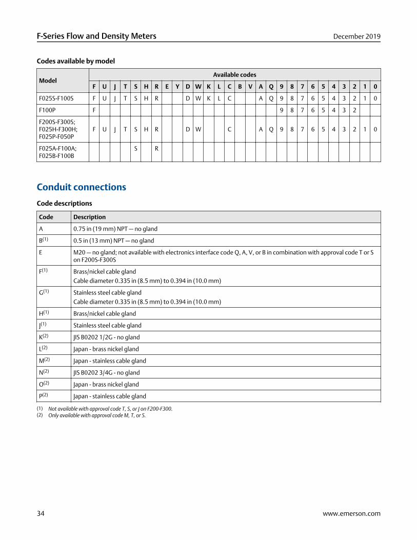
Codes available by model
ModelAvailable codes
F U J T S H R E Y D W K L C B V A Q 9 8 7 6 5 4 3 2 1 0
F025S-F100S F U J T S H R D W K L C A Q 9 8 7 6 5 4 3 2 1 0
F100P F 9 8 7 6 5 4 3 2
F200S-F300S;F025H-F300H;F025P-F050P
F U J T S H R D W C A Q 9 8 7 6 5 4 3 2 1 0
F025A-F100A;F025B-F100B
S R
Conduit connections
Code descriptions
Code Description
A 0.75 in (19 mm) NPT — no gland
B(1) 0.5 in (13 mm) NPT — no gland
E M20 — no gland; not available with electronics interface code Q, A, V, or B in combination with approval code T or Son F200S-F300S
F(1) Brass/nickel cable gland
Cable diameter 0.335 in (8.5 mm) to 0.394 in (10.0 mm)
G(1) Stainless steel cable gland
Cable diameter 0.335 in (8.5 mm) to 0.394 in (10.0 mm)
H(1) Brass/nickel cable gland
J(1) Stainless steel cable gland
K(2) JIS B0202 1/2G - no gland
L(2) Japan - brass nickel gland
M(2) Japan - stainless cable gland
N(2) JIS B0202 3/4G - no gland
O(2) Japan - brass nickel gland
P(2) Japan - stainless cable gland
(1) Not available with approval code T, S, or J on F200-F300.(2) Only available with approval code M, T, or S.
F-Series Flow and Density Meters December 2019
34 www.emerson.com
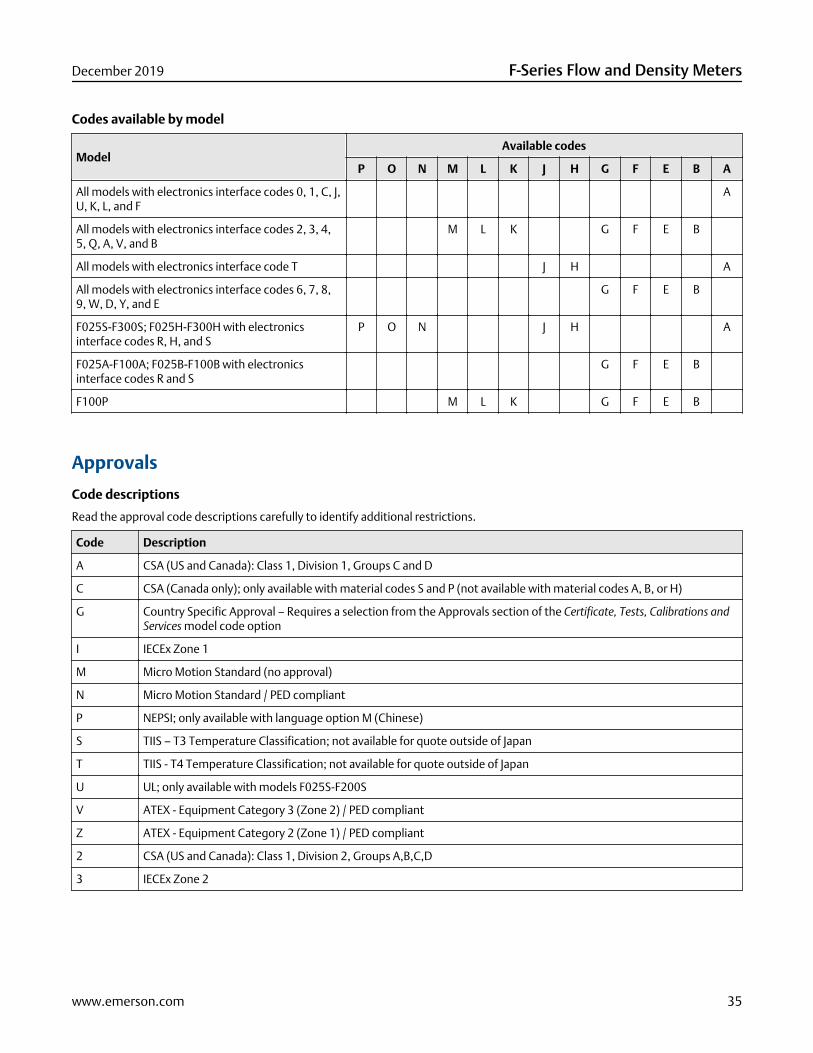
Codes available by model
ModelAvailable codes
P O N M L K J H G F E B A
All models with electronics interface codes 0, 1, C, J,U, K, L, and F
A
All models with electronics interface codes 2, 3, 4,5, Q, A, V, and B
M L K G F E B
All models with electronics interface code T J H A
All models with electronics interface codes 6, 7, 8,9, W, D, Y, and E
G F E B
F025S-F300S; F025H-F300H with electronicsinterface codes R, H, and S
P O N J H A
F025A-F100A; F025B-F100B with electronicsinterface codes R and S
G F E B
F100P M L K G F E B
Approvals
Code descriptions
Read the approval code descriptions carefully to identify additional restrictions.
Code Description
A CSA (US and Canada): Class 1, Division 1, Groups C and D
C CSA (Canada only); only available with material codes S and P (not available with material codes A, B, or H)
G Country Specific Approval – Requires a selection from the Approvals section of the Certificate, Tests, Calibrations andServices model code option
I IECEx Zone 1
M Micro Motion Standard (no approval)
N Micro Motion Standard / PED compliant
P NEPSI; only available with language option M (Chinese)
S TIIS – T3 Temperature Classification; not available for quote outside of Japan
T TIIS - T4 Temperature Classification; not available for quote outside of Japan
U UL; only available with models F025S-F200S
V ATEX - Equipment Category 3 (Zone 2) / PED compliant
Z ATEX - Equipment Category 2 (Zone 1) / PED compliant
2 CSA (US and Canada): Class 1, Division 2, Groups A,B,C,D
3 IECEx Zone 2
December 2019 F-Series Flow and Density Meters
www.emerson.com 35

Codes available by model
Model(1) With electronicsinterface code
Available codes
3 2 Z V U T S P N M J I G C A
All (except F100P) 0, 1, L, and K 3 2 V N M G
Q, A, V, and B Z T S P N M J I G C A
6, 7, 8, 9 Z P N M I G C A
C 3 2 Z T S P N M J I G C A
T Z N M I C A
W, D, Y, and E Z P N M I G C A
F 3 2 Z V T S N M I G A
F025H-F300H; F025S-F300S; F025P-F050P
R, H, and S Z U T S P N M J I G C A
F025H-F300H; F025S-F300S
2, 3, 4, 5 Z T S P N M J I G A
J and U 3 Z V T S N M J I G C A
F025A-F100A; F025B-F100B
R and S Z P N M I G A
F025P-F050P 2, 3, 4, 5 Z P N M I G A
J and U 3 Z V N M I G C A
F100P 2, 3, 4, 5 Z N M I A
6, 7, 8, 9 Z N M I A
J and U 3 Z V N M I A
F 3 2 Z V T S N M I G A
(1) Read the approval code descriptions carefully to identify additional restrictions.
Languages
Code Language option
A Danish CE requirements document and English installation manual
D Dutch CE requirements document and English installation manual
E English installation manual
F French installation manual
G German installation manual
H Finnish CE requirements document and English installation manual
I Italian installation manual
J Japanese installation manual
M Chinese installation manual
N Norwegian CE requirements document and English installation manual
P Portuguese installation manual
F-Series Flow and Density Meters December 2019
36 www.emerson.com

Code Language option
S Spanish installation manual
W Swedish CE requirements document and English installation manual
B Hungarian CE requirements document and English installation manual
K Slovak CE requirements document and English installation manual
T Estonian CE requirements document and English installation manual
U Greek CE requirements document and English installation manual
L Latvian CE requirements document and English installation manual
V Lithuanian CE requirements document and English installation manual
Y Slovenian CE requirements document and English installation manual
Additional standard approvals
Code Additional standard approvals
Z No additional standard approval options selected; does not apply to F100P
Z Rated to 5,220 psi (360 bar) – no additional standard approval options selected; only applies to F100P
N Rated to 5,220 psi (360 bar) – all nickel alloy C22 components comply with NORSOK M-650 where applicable
H Rated up to 6,250 psi (431 bar) – no additional standard approval options selected
K Rated up to 6,250 psi (431 bar) – all nickel alloy C22 components comply with NORSOK M-650 where applicable
Calibration
Code Calibration option
Z ±0.20% mass and 0.002 g/cm³ (2 kg/m³) density calibration
A ±0.15% mass and 0.002 g/cm³ (2 kg/m³) density calibration
Not available on all models
1 ±0.10% mass and 0.001 g/cm³ (1 kg/m³) density calibration
Not available on all models
C ±0.10% mass and 0.002 g/cm³ (2 kg/m³) density calibration
Not available on all models
K ±0.10% mass and 0.0005 g/cm³ (0.5 kg/m³) density calibration
Not available on all models
2 ±0.05% mass and 0.0005 g/cm³ (0.5 kg/m³) density calibration
Not available on all models
December 2019 F-Series Flow and Density Meters
www.emerson.com 37

Measurement application software (all models)
Code Measurement application software option
Z No measurement application software
Factory options
Code Factory option
Z Standard product
X ETO product
R Restocked product (if available)
Certificates, tests, calibrations, and servicesThese option codes can be added to the end of the model code if needed, but no code is required when none of these options isselected.
NoteThere may be additional options or limitations depending on total meter configuration. Contact a sales representative beforemaking your final selections.
Material quality examination tests and certificates
Select as many codes from this table as required.
Code Factory option
MC Material inspection certificate 3.1 (supplier lot traceability per EN 10204)
NC NACE certificate 2.1 (MR0175 and MR0103)
KH KHK package 3.1 — certificate package to accommodate approval in Japan. Includes:■ Radiographic and tube wall examination
■ HSB witness primary containment hydrostatic and pneumatic testing
■ Material inspection certificate
Not available with codes RI, RC, HT, MC (because they are already included); not available with nickel alloy C22models (F025H–F300H or F025B–F100B)
Radiographic testing
Select only one code from the following table.
Code Factory option
RE X-ray package 3.1 (radiographic examination certificate; weld map; radiographic inspection NDE qualification)
RT X-Ray package 3.1 (radiographic examination certificate with digital image; weld map; radiographic inspection NDEqualification)
F-Series Flow and Density Meters December 2019
38 www.emerson.com

Pressure testing
Code Factory option
HT Hydrostatic test certificate 3.1 (wetted components only)
Dye penetrant examination
Code Factory option
D1 Dye penetrant test package 3.1 (Liquid Dye Penetration NDE Qualification):■ Process connection only for F300 sensors
■ Sensor only for all other sensor models
Weld examination
Code Factory option
WP Weld procedure package (weld map, weld procedure specification, weld procedure qualification record, welderperformance qualification)
Positive material testing
Select only one from this group.
Code Factory option
PM Positive material test certificate 3.1 (without carbon content)
PC Positive material test certificate 3.1 (including carbon content); not available with nickel alloy C22 models (F025H–F300H or F025B–F100B)
ASME B31.1 power piping design code certification
Code Factory option
GC B31.1 power piping design code certification; not available with F100P
Special cleaning
Code Factory option
O2 Declaration of compliance oxygen service 2.1
Accredited calibration
Code Factory option
IC ISO17025 accredited calibration and certificates (9 points total)
Special calibration options
Select either none, CV, or CV with one of the additional verification point options.
NoteMinimum flow rates may apply when selecting the special calibration option.
December 2019 F-Series Flow and Density Meters
www.emerson.com 39

Code Factory option
CV Custom verification (alter original verification points)
01 Add 1 additional verification point
02 Add 2 additional verification point
03 Add 3 additional verification point
06 Add up to 6 additional verification points
08 Add up to 8 additional verification points
16 Add up to 16 additional verification points
Weights & Measures
Code Factory option
WM Tag for US NTEP certified applications; not available on F100P or any F025 or F300 models
WC Tag for Measurements Canada certified applications; not available with approval code P
Sensor completion
Select as many codes from this table as required.
Code Factory option
WG Witness general
SP Special packaging
Country specific approvals
Select one of the following if approval code G is selected. Not available on F100P.
Code Factory option
R1 EAC Zone 1 – Hazardous Approval
Not available with electronics code 0 or 1.
R3 EAC Zone 2 – Hazardous Approval
Only available with electronics code 0,1, J, U, K, and L.
B1 INMETRO Zone 1 – Hazardous Approval
Not available with electronics code 0 or 1.
B3 INMETRO Zone 2 – Hazardous Approval
Only available with electronics code 0,1, J, U, K, and L.
Other electronics interface
Code Factory option
UA 4200 integral mount aluminum housing
F-Series Flow and Density Meters December 2019
40 www.emerson.com

December 2019 F-Series Flow and Density Meters
www.emerson.com 41

F-Series Flow and Density Meters December 2019
42 www.emerson.com

December 2019 F-Series Flow and Density Meters
www.emerson.com 43
PS-00603Rev. AE
December 2019
Emerson Automation SolutionsWorldwide Headquarters7070 Winchester CircleBoulder, Colorado USA 80301T: +1 800-522-6277T: +1 303-527-5200F: +1 303-530-8459Mexico: +52 55 5809 5300Argentina: +54 11 4837 7000Brazil: +55 15 3413 8000Chile: +56 2 2928 4800Peru: +51 15190130
Emerson Automation SolutionsCentral Europe: +41 41 7686 111Eastern Europe: +41 41 7686 111Dubai: +971 4 811 8100Abu Dhabi: +971 2 697 2000Austria: +43 2236 607-0France: +33 (0) 800 917 901Germany: +49 (0) 2173 3348 0Italy: +39 8008 77334The Netherlands: +31 318 495 555Belgium: +32 2 716 77 11Spain: 900 901 983U.K. and Ireland: 0870 240 1978Russian/CIS: +7 495 995 9559
Emerson Automation SolutionsAustralia: (61) 3 9721 0200China: (86) 21 2892 9000India: (91) 22 6662 0566Japan: (81) 3 5769 6803South Korea: (82) 31 8034 0000Singapore: (65) 6 363 7766
©2020 Micro Motion, Inc. All rights reserved.
The Emerson logo is a trademark and service mark of Emerson Electric Co. Micro Motion, ELITE,ProLink, MVD and MVD Direct Connect marks are marks of one of the Emerson AutomationSolutions family of companies. All other marks are property of their respective owners.