micro-hydro power generation in the case of power
TRANSCRIPT

IET Renewable Power Generation
Research Article
Proportional-resonant control applied onvoltage regulation of standalone SEIG formicro-hydro power generation
ISSN 1752-1416Received on 10th October 2016Revised 28th December 2016Accepted on 17th January 2017E-First on 10th February 2017doi: 10.1049/iet-rpg.2016.0857www.ietdl.org
Celso Becker Tischer1 , Jonas Roberto Tibola1, Lucas Giuliani Scherer1, Robinson Figueiredo deCamargo1
1Federal University of Santa Maria — UFSM, 97105-900 — Santa Maria, RS, Brazil E-mail: [email protected]
Abstract: This study deals with the development of a proportional-resonant (PR) control applied on voltage regulation andharmonics compensation of a standalone self-excited induction generator (SEIG) for micro-hydro power generation system. Thegeneration system considers: (i) a three-phase induction generator (IG) as SEIG, (ii) which is driven by an unregulated micro-hydro turbine, (iii) a three-phase three-legs distribution static synchronous compensator (DSTATCOM) and (iv) linear and non-linear loads connected to the AC bus. The voltage regulation is performed through the injection of reactive power to the AC busthrough the DSTATCOM, providing excitation current to the IG. It is considered the employment of PR control techniques, whichoffers suitable voltage regulation through voltage harmonics compensation in the point of common coupling. Furthermore,frequency regulation is performed on the demand side by an electronic load control connected to the DC bus of theDSTATCOM. Experimental results were obtained to demonstrate the good performance of the voltage and frequency regulation,provided by the control system during transients of linear and non-linear loads.
1 IntroductionThe use of renewable energy sources, such as hydro, wind, biomassand solar, has increased considerably to electricity generation inremote and rural communities mainly those in hilly and remoteregions. Often, the electric power demanded by these communitiesis in the range of 1 to 100 kW and isolated micro-grids appears tobe the best solution for that, eliminating the high-cost investmentrequired for transmission line by conventional transmission/distribution system. Among several renewable energy sources,micro-hydro shows a great promise as it is environmentallyfriendly, pollution free and does not result in large deforestation[1]. Practical examples of standalone micro hydro-powergeneration systems are presented in [2–4].
Self-excited induction generators (SEIGs) applied in micro-hydro power generating system presents advantages compared withthe conventional synchronous generator, such as absence of DCexcitation, brushless construction, ruggedness and inherent short-circuit protection [5–8]. Despite the attracting features, the terminalvoltage and output frequency of SEIG are not guaranteed just withthe self-excitation of the induction generator (IG) by shunt-connection of a capacitor bank and hence, voltage and frequencycontrollers are required for such systems [9, 10].
Several voltage regulating schemes have been proposed byresearchers to control the terminal voltage of SEIG, such asswitching reactive banks by semiconductor devices, as the onesbased on static VAr compensators, and more recently the based onconverters, such as voltage source converter (VSC)-baseddistributed static synchronous compensators (DSTATCOMs) [11–14]. The topologies using DSTATCOM offer enhancedperformance and advantages in terms of voltage regulation, once itoffers superior dynamic response compared with other availableschemes and does not inject lower order harmonics into the system[15–18].
Non-linear loads drain non-sinusoidal currents from thegenerating system, injecting harmonic currents in it. Injectedharmonics may pollute the generated voltage as the standaloneSEIG is usually small in size. The DSTATCOM compensates theharmonic currents and supplies the reactive power to the load andgenerator. However, to take advantage of all the features of the
DSTATCOM, the applied control techniques must be robust andintroduce accuracy and fast transient response.
The method of generation of reference signals is a major issuewhich affects the performance of the DSTATCOM [19]. Inliterature the estimation of current reference for the DSTATCOM isusually addressed using instantaneous reactive power theory,synchronous reference frame theory, and modified p-q theory [20].Most of these schemes have complex control and do notcompensate the ripples or delay realised in computation ofreference signals [21].
Another issue for DSTATCOM proper operation is the currentcontrol. The evolution of DSPs, turned feasible the use of manydigital control techniques, as such the proportional-integral (PI)controller, which is traditionally fed by the error signal todetermine the gate signal of the DSTATCOM. However, in thepresence of non-linear loads, PI controllers are unable tocompensate the current harmonics due its limited bandwidth [22–27]. Hysteresis control is a widely used current control technique inmost of the DSTATCOM, but this control scheme suffers fromcertain disadvantages of wide variation in switching frequency andhigher losses of the inverter switches due to an increased numberof switching per cycle [28–33].
The proportional-resonant (PR) controllers, based on theinternal model principle, have been employed with satisfactoryresults in several power converters applications, such as, activepower filters, hydro and wind generation systems, photovoltaicinverters, dynamic voltage restorers, active rectifier motor drivesand fuel cell inverters [34]. This controller is commonly used toprovide an infinite gain at chosen frequencies in order to ensuretracking for sinusoidal references and to ensure rejection ofdisturbance harmonics at specific frequencies [20, 25, 26, 35–37].In the case of power generator applications, a set of resonantcontrollers can be used to ensure perfect disturbance rejection withzero steady-state error at the fundamental frequency [14].
In terms of frequency regulation, two main different scenariosreferent to the primary machine are usually considered: constant-speed constant-frequency; and variable-speed constant-frequency(VSCF) [38]. The first case considers the continuous adjustment ofthe primer machine to keep its speed constant, by means of speedgovernors. The second case, the prime machine imposes a specific
IET Renew. Power Gener., 2017, Vol. 11 Iss. 5, pp. 593-602© The Institution of Engineering and Technology 2017
593

speed on the IG rotor and the stator frequency regulation must bedone by the auxiliary load, which is known in the literature aselectronic load control (ELC), controlled to consume all theexceeding generated power [7, 11, 17, 18, 39]. In SEIG-basedmicro-hydro power generation (<100 kW) VSCF is preferablebecause usually there is no reservoir, being the water flow constant[18].
This paper deals with the analysis, design and implementationof the PR control applied on voltage regulation and harmonicscompensation of a SEIG-based micro-hydro power generation. Thecontrol strategy proposed presents the integration of outer voltageloops running on rotating frame and inner current loops using PRcontrollers running on stationary frame, it offers advantages suchas harmonic currents mitigation, stable DC-link voltage duringtransient conditions and the terminal voltage with null error insteady-state conditions. Besides, the frequency regulation isperformed by means of an ELC composed by a chopper with anauxiliary load connected to the DC bus of DSTATCOM, beingcontrolled by a PI controller considering the nominal frequency ofthe system as reference. The parameters of power quality at pointof common coupling (PCC), considered for the analysis of theregulation system, are defined by the Institute of Electrical andElectronics Engineers (IEEE)-519 standard [40].
This paper is organised as follows: Section 2 presents theconfiguration of the micro-hydro power generation system and themodelling of the three-phase system. The control structure,including voltage and frequency control and designing principlesapplied to the current control, are present in Section 3. Finally, theexperimental results, taken from a prototype generation system, aregiven in Section 4 to validate the proposed control.
2 System configurationThe proposed system consists of a three-phase three wires IGmechanically coupled with an uncontrolled hydro turbine. The IGterminals are shunt connected to an excitation capacitor bank,consisting in the SEIG, from what derives the PCC. TheDSTATCOM is connected to the PCC through of an inductivefilter. At the DSTATCOM's DC-link is connected an ELC, which iscomposed by an insulated-gate bipolar transistor (IGBT) chopperand an auxiliary load (RELC). The schematic diagram of the wholesetup, considered as a micro-hydro power generation system, isshown in Fig. 1.
The prime mover, coupled to the SEIG, is considered anunregulated turbine with no real time control of mechanical powersupplied to IG's shaft. For this reason, the voltage frequencydepends on the balance between input mechanical power andoutput electrical power of the SEIG. Therefore, to keep thefrequency regulation, the electrical power generated by the SEIGmust be consumed by the loads plus the ELC and DSTATCOM.Since the loads connected to the AC bus are unknown, the ELC isused to consume the excess power generated by the SEIG.
The DSTATCOM is an IGBT three-legs VSC with a dedicatedcontrol system developed in a DSP. The combination ofDSTATCOM and ELC controls the voltage and frequency of the
system simultaneously during load perturbations, which allowsactive and reactive power regulation. As proposal, the powergeneration system must be capable of feeding three-phase linearand non-linear consumer loads, with unit power factor or not.
2.1 System modelling
This section deals with the system modelling, which is indeedimportant for the design of the controllers applied on the regulationof the system described in Fig. 1. For that, a few assumptions areconsidered:
• The IG is assumed to be in steady-state operation, and its modelis the IG equivalent circuit per-phase in steady-state as presentedin [41], which is composed by a stator and rotor resistance(Rs, Rr′), stator, rotor and mutual inductances (Ls, Lr′, Lm), rotorvoltage (Var), and rated slip (s). A simplified model, moresuitable for control purpose, can be achieved using Theveninequivalent circuit composed by a sinusoidal voltage source (vg)and an inductance (Lg) in series with a resistance (Rg). Theparameters (Rg, Lg) of the equivalent Thevenin circuit can befound as shown below:
Rg = Rs + Rr′Lm
2 ω2
R′r2 + ω2 Lm + L′r
2 (1)
Lg =R′r
2 Lm + Ls + ω2 Lm2 L′r
2 + Ls Lm + L′r2
R′r2 + ω2 Lm + L′r
2 (2)
where ω is the electric frequency.• the input DC-link voltage vdc is represented as a constant DC
input source;• the inverter switches are considered ideal;• the inductance of DSTATCOM output filter are identical with
the same value;• the switching frequency is much higher than the frequency of
the fundamental voltage, which allows to neglect the effect ofthe high order pulse-width modulation (PWM) harmonics;
• the DSTATCOM is replaced by a voltage source with voltagevalue equal to its average value inside the PWM period;
• the variables are sampled at its average values.
Considering the assumptions above, one can obtain a set of statevariables equations of the micro-hydro power generation system:
xabc = Aabcxabc + Babcuabc + Fabcvabc (3)
which gives a model with nine state variables as
xabc = iga igb igc vCa vCb vCc ista istb istcT (4)
Fig. 1 Schematic diagram of the proposed micro-hydro power generation system
594 IET Renew. Power Gener., 2017, Vol. 11 Iss. 5, pp. 593-602© The Institution of Engineering and Technology 2017
three voltage control inputs variables uabc = u1 u2 u3 , andthree disturbance inputs, vabc = vga vgb vgc , where the voltagesare estimated from the line-to-line voltages using thetransformation given in Appendix 7.1, igx is the generator current,vCx is the capacitor voltage and istx is the DSTATCOM current inx = a b c coordinates.
The matrices Aabc, Babc and Fabc are defined as:
Aabc =I3 × 3 −Rg/Lg Ap1 03 × 3
I3 × 3 1/C I3 × 3 −1/RLC I3 × 3 −1/C03 × 3 Ap2 I3 × 3 −Rf /Lf
,
Babc =03 × 3
03 × 3
−Ap2
, Fabc =− Ap1
03 × 3
03 × 3
(5)
where C is the excitation capacitance, RL is the load resistance, Lfand Rf are the filter inductance and resistance, respectively, andIi × j is the identity matrix with dimensions equal to i rows and jcolumns. The coefficients of (5) are
Ap1 =−2/3Lg 1/3Lg 1/3Lg
1/3Lg −2/3Lg 1/3Lg
1/3Lg 1/3Lg −2/3Lg
,
Ap2 =2/3Lf −1/3Lf −1/3Lf
−1/3Lf 2/3Lf −1/3Lf
−1/3Lf −1/3Lf 2/3Lf
.
(6)
Now, by representing this state-space equation in the stationary αβframe, to obtain an uncoupled single-phase system, the state-spacemodel (7) is obtained, using the linear transformation given inAppendix 7.1. Note that, in three-wire three-phase DSTATCOM,there is no path for the axis 0 current. Therefore, the state-spaceequations can be represented by xαβ = Aαβxαβ + Bαβuαβ + Fαβvαβwhere the states variables arexαβ = igα igβ vCα vCβ istα istβ
T, uαβ = uα uβT,
vαβ = vα vβT and the matrices are given as,
Aαβ =I2 × 2 −Rg/Lg I2 × 2 −1/Lg 02 × 2
I2 × 2 1/C I2 × 2 −1/RLC I2 × 2 −1/C02 × 2 I2 × 2 1/Lf I2 × 2 −Rf /Lf
,
Bαβ =02 × 2
02 × 2
I2 × 2 −1/Lf
, Fαβ =I2 × 2 1/Lg
02 × 2
02 × 2
.
(7)
The sinusoidal components in the stationary αβ frame can beexpressed as constant magnitudes in the synchronous dq frameusing the Park's transformation given in Appendix 7.1. Thus, thestate-space equations can be represented asxdq = Adqxdq + Bdqudq + Fdqvdq, where
xdq = igd igq vCd vCq istd istqT, udq = ud uq
T andvdq = vd vq
T, it can be expressed as
Adq =Ap1 I2 × 2 −1/Lg 02 × 2
I2 × 2 1/C Ap2 I2 × 2 −1/C02 × 2 I2 × 2 1/Lf Ap3
,
Bdq =02 × 2
02 × 2
I2 × 2 −1/Lf
, Fdq =I2 × 2 1/Lg
02 × 2
02 × 2
(8)
where the coefficients of (8) are given as
Ap1 =−Rg/Lg −ω
ω −Rg/Lg, Ap2 =
−1/RLC −ωω −1/RLC
,
Ap3 =−Rf /Lf −ω
ω −Rf /Lf.
(9)
The models obtained in αβ and dq coordinate systems are used todesign a cascaded control strategy. Where, the inner loop is thecurrent control loop performed in αβ reference frame, and the outerloop is the AC voltage control loop and DC-link voltage controlloop performed in dq reference frame.
The αβ current controller design is performed in frequencydomain. Therefore, a transfer function that relates the DSTATCOMαβ currents with the control variables can be defined as,
Gistαβ, uαβs =
istα suα s =
istβ suβ s = Cαβ sI − Aαβ
−1Bαβ (10)
where, Cαβ = 0 0 0 0 1 0 orCαβ = 0 0 0 0 0 1 , since istα = istβ. The cross couplingbetween αβ axis are disregarded, since its dynamical influence areminimal and can be compensated in the control loop.
The outer AC voltage control loop is performed in dqsynchronous frame by injection of the current component istq.Therefore, a relationship between the output voltage vCd (vCq = 0due dq synchronous orientation) and the istq need to be achieved. Asimple way to achieve this transfer functions is given by
GvCd, istqs =
vCd sistq s =
GvCd, uds
Gistq, uds =
CdqvC sI − Adq
−1Bdq
Cdqiq sI − Adq
−1Bdq
(11)
where CdqvC = 0 0 1 0 0 0 and
Cdqiq = 0 0 0 0 0 1 .
The transfer function that defines the behaviour of DC-linkvoltage is obtained through the power balance between AC andDC-link of the DSTATCOM, being defined by
Gvdc, istds =
vdc2 s
istd s = −2vCdCdcs
(12)
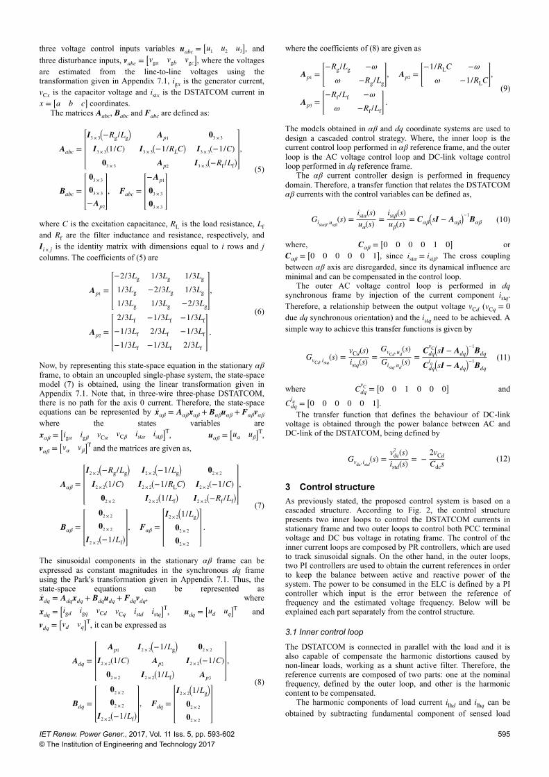
3 Control structureAs previously stated, the proposed control system is based on acascaded structure. According to Fig. 2, the control structurepresents two inner loops to control the DSTATCOM currents instationary frame and two outer loops to control both PCC terminalvoltage and DC bus voltage in rotating frame. The control of theinner current loops are composed by PR controllers, which are usedto track sinusoidal signals. On the other hand, in the outer loops,two PI controllers are used to obtain the current references in orderto keep the balance between active and reactive power of thesystem. The power to be consumed in the ELC is defined by a PIcontroller which input is the error between the reference offrequency and the estimated voltage frequency. Below will beexplained each part separately from the control structure.
3.1 Inner control loop
The DSTATCOM is connected in parallel with the load and it isalso capable of compensate the harmonic distortions caused bynon-linear loads, working as a shunt active filter. Therefore, thereference currents are composed of two parts: one at the nominalfrequency, defined by the outer loop, and other is the harmoniccontent to be compensated.
The harmonic components of load current ilhd and ilhq can beobtained by subtracting fundamental component of sensed load
IET Renew. Power Gener., 2017, Vol. 11 Iss. 5, pp. 593-602© The Institution of Engineering and Technology 2017
595
currents in d- and q-axis (ilfd and ilfq), achieved through a 2nd orderlow pass filter), from its load current as
ilhd = ild − ilfd (13)
ilhq = ilq − ilfq (14)
The alternated signals on stationary frames of reference currents ofactive and reactive power defined by outer loops (ivα
∗ and ivβ∗ ) and
harmonic component of actual load (ilα∗ and ilβ
∗ ) (i.e. consumer load)are obtained using the inverse Park's transformation given inAppendix 7.1. These reference currents are compared with thesensed DSTATCOM currents in stationary frames (istα and istβ) andthen the current errors (eiα and eiβ) are fed to the PR controlleremployed for current control. The current errors are defined as
eiα = ivα∗ + ilα
∗ − istα (15)
eiβ = ivβ∗ + ilβ
∗ − istβ (16)
The output of the PR controllers are applied to a phasecompensator to improve open loop phase margin at the zerocrossing gain frequency. The output of the phase compensator uαand uβ are the control actions, which are used to generate the PWMsignals to be applied to the IGBT switches of the DSTATCOM.The PWM signals (uPWM) are generated using the geometricmodulation in accordance to [42]. The following subsectiondescribes control design.
3.2 Inner control loop design
As previously stated, PI controllers are considered unsatisfactory totrack sinusoidal signals on stationary frames in order tocompensate harmonic distortions caused by non-linear loads.Therefore, to ensure tracking of sinusoidal reference, PRcontrollers based on the internal model principle [43] are used.
As its main feature, the PR controller is able to provide infinitegain at the resonance frequency. This effect is the result of thepresence of resonant poles and conceptually equal to an integratorwith infinite gain for continuous signals, which forces the error tozero in steady-state. In the frequency domain, the PR controller isdefined as [20],
GPR(s) = kP +2kRξωns
s2 + 2ξωns + ωn2 (17)
In this representation, ωn is the frequency of resonant controller, ξis a damping factor, kR is the resonant gain and kP is theproportional gain of the resonant controller. This controllerachieves infinite gain in a narrow frequency band around theresonance frequency, which is directly related with the dampingfactor ξ. On the other hand, the proportional gain kP determines thedynamics in terms of phase of the bandwidth and gain margin, andit is tuned in a similar way to the PI controller.
In the general case, a set of PR controllers can be used tocompensate several fixed and known frequencies. This can beachieved by adding more resonant terms in (17). The multipleresonant controllers can be represented as
GPR(s) = kP + ∑h = 1, 5, 7, 11…
2kRhξhωnss2 + 2ξhωns + (hωn)
2 (18)
where, h is the harmonic order to be compensated and kRhrepresents the individual resonant gain.
Resonant controllers are used to ensure reference tracking anddisturbance rejection, however the transient results of thesecontrollers are not generally satisfactory. Thus, as explained before,it is proposed the use of a phase compensator. This phasecompensation is obtained through the use of the transfer functiongiven by,
GPH(s) =s + ω f Z
s + ω f P
(19)
where ω f Z and ω f P
is the zero and pole location of the phasecompensator, respectively.
According to Erickson and Maksimovic [44], the maximumachievable phase compensation (θ) of GPH, occurs at the geometricmean of the pole and zero frequency. Besides that, (θ) is usuallyplaced at the desired zero crossing gain frequency ( f c). Thisspecification is obtained when the frequency location of the zero( f Z) and the pole ( f P) is made according to,
f Z = f c1 − sin(θ)1 + sin(θ) , f P = f c
1 + sin(θ)1 − sin(θ) (20)
Fig. 2 Block diagram of proposed voltage and frequency regulator for SEIG
596 IET Renew. Power Gener., 2017, Vol. 11 Iss. 5, pp. 593-602© The Institution of Engineering and Technology 2017
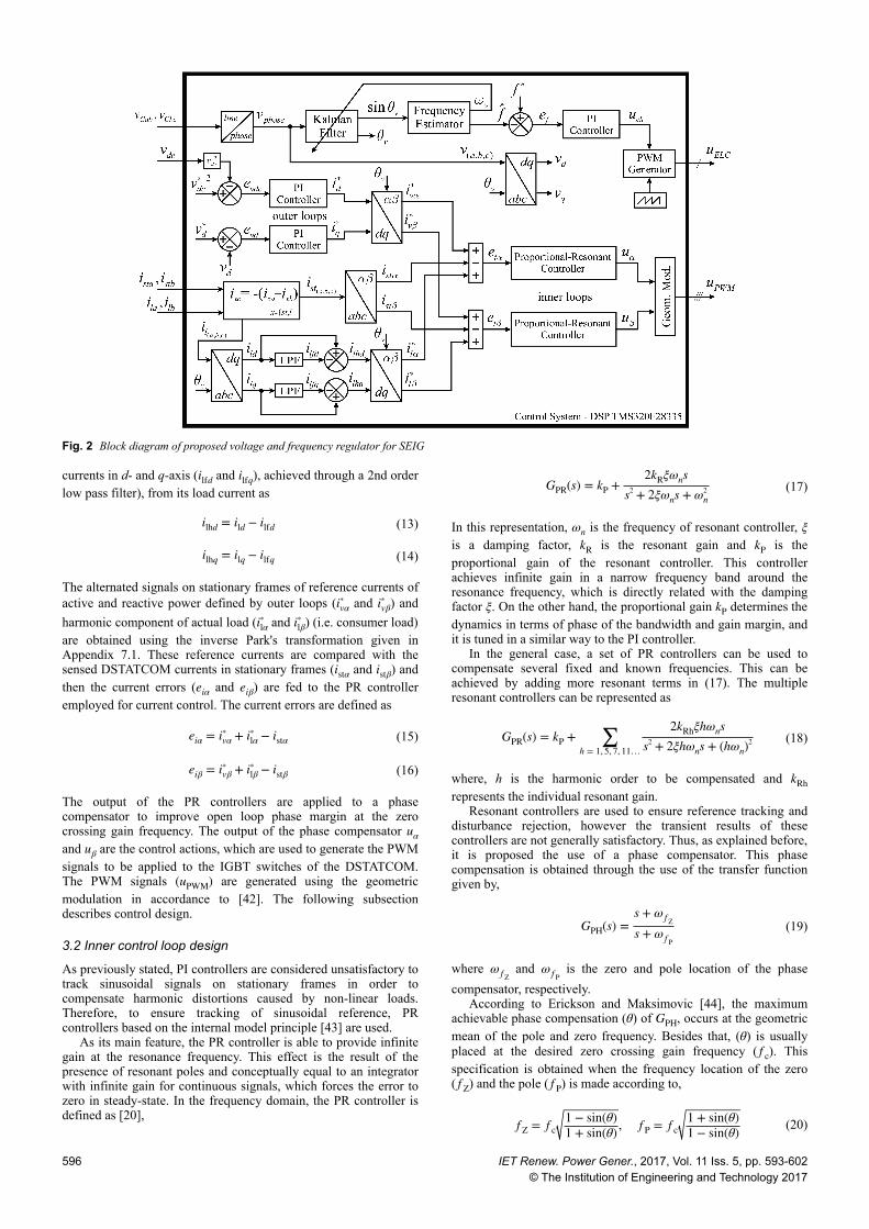
The system current control diagram is presented in Fig. 3a. Itconsists of a set of resonant proportional compensation block forreference tracking in steady-state, and a phase compensator block,designed in order to ensure an adequate phase margin, the zero gaincrossover frequency. The output the phase compensator are thecontrol actions uα and uβ.
The aim of the control design proposed is to obtain controllersgains to ensure: (i) zero steady-state error, (ii) good transientresponse and (iii) system current reference tracking and PCCvoltage disturbance rejection.
The following procedure can be taken to get a PR controller.First, choose (ωn) in (18) for each resonant controller, taking intoaccount that these frequencies are related with the frequency of thecurrent reference to be tracked and the frequencies of the loadharmonics to be compensated. Second, choose a damping factor (ξ)for each resonant controller in (18). Third, get the phase angle (θ)needed to match the desired phase margin at the open-loop zerogain crossover frequency. Fourth, use angle (θ) to find the pole andzero in (20) of the phase compensation portion and adjust thecurrent controller gain until the desired phase margin, afterwarddiscretise the compensator (19) and each resonant controller withTustin discretisation method.
3.3 Outer control loop
As stated before the outer loops are responsible to control both DC-link voltage and PCC voltage. The outer loops are performed bytwo PI controllers, in dq frame, whose define the reference currentfor the inner loops. The PI controller for d-axis is responsible tomaintain DC-link voltage at its reference value. This controllergives the reference current id
∗ as described in Fig. 3b, which processthe active power to charge the DC bus, to keep the DSTATCOMoperational and to supply power to the ELC, which is described inthe next subsection.
The outer loops bandwidths are set at least one decade below ofthe current control loops bandwidths. Thus, it can be considered nointeraction between outer and inner loops, what leads, from theouter loop point of view id
∗ = id and iq∗ = iq. This fact simplifies the
outer loop design, since the inner loop is considered as an unitarygain. On the other hand the PI controller for q-axis is responsible tocontrol PCC voltage at its reference value. This controller gives thereference current iq
∗, which process the reactive power supplied tothe IG, and eventually to the load. The PCC voltages are sensedand transformed to dq frame using Clark's and Park'stransformation described in Appendix 7.1. As the voltage vector isaligned with the PCC voltage angle, therefore (vq = 0) and vdcorrespond to the rms (root mean square) value of the PCC linevoltage (vCab), as described in Fig. 3c.
3.4 Frequency control and synchronisation method
An unregulated hydro turbine is considered as the prime mover,and the frequency control is performed on the demand side by anELC. The ELC is composed by an IGBT chopper connected to theDC bus of DSTATCOM, as presented in Fig. 1.
The voltage frequency depends on the balance between inputmechanical power and output power of the SEIG. Therefore, thepower consumed by the system must be maintained constantirrespective of the load variations. The ELC is used to consume theexcess power generated by the SEIG.
The ELC control is based on the estimated PCC terminalvoltage frequency, which is performed by a Kalman-basedsynchronisation method followed by a frequency identificationalgorithm [45]. The Kalman filter is well known due its ability todeal with linear systems corrupted by uncertainties in the states ofthe plant as well as measurement noise [46].
The estimated frequency ( f^) is then compared with the
reference value, which generates a frequency error, ef = f ∗ − f^.
The error is fed to a PI controller which defines the power to beconsumed by the ELC (PELC). The relationship between the powerto be consumed by the ELC, and the control action (uch) imposedby the element chopper over the RELC is defined by,
uch = PELC ⋅ RELC (21)
The uch is modulated to generate a PWM signal (uELC) to beapplied to the IGBT which drives the RELC.
4 Discussion and experimental resultsIn this section, the design of PR controller is carried out and theperformance of the system is presented. Experimental validation isalso provided, based on a prototype that emulates a micro-hydropower standalone generation system, as shown in Fig. 4, in whichthe uncontrolled hydro turbine is emulated by an induction motordriven by a frequency inverter. The prototype also count with athree-phase IGBT DSTATCOM, Hall effect sensors for voltage andcurrent measurements, and a floating point DSP (Texas Instrumentsmodel TMS320F28335) for control algorithm implementation.
The parameters of the experimental prototype, includingparameters of SEIG, DSTATCOM, ELC and PI controllers gainsare presented in Appendix 7.2. For the resonant controllers, oneuses the choices of the fundamental (60 Hz), fifth, seventh,eleventh and thirteenth harmonics, proportional gain kP = 0.999986and ξ = 0.00001 for all frequencies. The design requirements forcurrent controller are a gain crossover frequency of 1 kHz and aphase margin >40°. Applying the designing steps described above,the PR control gains are obtained.
Fig. 3 Diagram of the controllers(a) PR regulator in the αβ reference frame, (b) PI regulator for DC-link voltage loop in the d reference frame, (c) PI regulator for PCC voltage loop in the q reference frame
IET Renew. Power Gener., 2017, Vol. 11 Iss. 5, pp. 593-602© The Institution of Engineering and Technology 2017
597

kRhξ =
0.02637999538086390.02615698579350150.02593773434969550.02530151089265820.0248944286635638
(22)
The phase lead compensator obtained is given by the transferfunction in discrete domain as
GPH(s) = 0.77008(z − 0.6833)(z − 0.3619) (23)
The Bode diagram of the current control system that relates thereference currents and the DSTATCOM current istαβ in open-loop isshowed in Fig. 5a. Note the high attenuation of grid voltageharmonics to the control current at the 60 Hz, as well as for 5, 7, 11and 13° harmonics. The internal model principle can be observedin the Bode diagram in closed-loop showed in Fig. 5b, once the
magnitudes and phases remain equal to 0 dB and 0 degrees,respectively, for resonant frequencies.
The relationship between the PCC voltage, in dq frame (vCd),and the istq is given in (11) and it is used to design q-PI controller,with a zero gain crossover frequency of 7.34 Hz and a phasemargin between 60 and 80°. On the other hand, the relationshipbetween the DC-link voltage vdc and the istd is given in (12) and itis used to design the d-PI controller, with a zero gain crossoverfrequency of 47.6 Hz and a phase margin between 70 and 90°. Theopen-loop Bode diagrams for the outer loops are shown in Figs. 5cand d, respectively.
The performance of reference tracking of inner and outer loopscontrollers is established through experimental tests carried out inthe system. The current reference ivα
∗ and DSTATCOM current istαare presented in Fig. 6a. Note that, a step in the reference isimplemented and, at instant 0.26 s, is performed a phase variationin the reference. Fast transients and good tracking response of thePR controller can be noticed. Results with similar response can beseen in Fig. 6b, for current tracking in β coordinate.
The voltage reference vd∗ and PCC voltage in the d-axes are
presented in Fig. 6c. It is possible to observe the good response ofthe controller when occurs the change in the reference value. Theresponse of the DC-link voltage controller can be verified inFig. 6d, where, initially it is set in 450 V and, at instant 2 s, ischanged to 350 V. From this result, it is possible to verify the goodperformance of the PI controllers employed in the outer loops.
The steady-state performances of hydropower system feeding abalanced non-linear load are presented in Figs. 7 and 8. A three-phase diode bridge rectifier feeding series R − L load is used asnon-linear load. Figs. 7a–c shows the waveforms of PCC voltage(vCab) along with its SEIG current (iga), load current (ila) of ‘a’phase and the DSTATCOM current (ista) injected in the ‘a’ phase.Since the system is feeding a non-linear load, the DSTATCOMinjects non-linear currents to suppress the load harmonics thatkeeps the SEIG currents almost sinusoidal and the voltage andfrequency are maintained at rated value, 220 V and 60 Hz,
Fig. 4 Experimental prototype of micro-hydro power generation system
Fig. 5 Frequency responses of the system(a), (b) Current control system in open-loop and closed-loop, (c) Outer loop in open-loop in the q reference, (d) Outer loop in open-loop in the d reference
598 IET Renew. Power Gener., 2017, Vol. 11 Iss. 5, pp. 593-602
© The Institution of Engineering and Technology 2017

respectively. The consumer load power (Pload) is shown in Fig. 7d.It can be seen that the load is consuming an active power of 3.56 kW along with a reactive power of 0.18 kVAr.
Figs. 8a–c shows harmonic spectra of vCab, vCbc and iga out ofwhich PCC voltage total harmonic distortion (THD) is observed as3.1 and 3.3%. The THD of SEIG current is noticed to be less than5%, thereby the compliance with the IEEE-519 standard for THDand harmonic content are corroborated. Fig. 8d shows the harmonicspectrum of consumer load current ila and its THD is observed tobe around 27.5%.
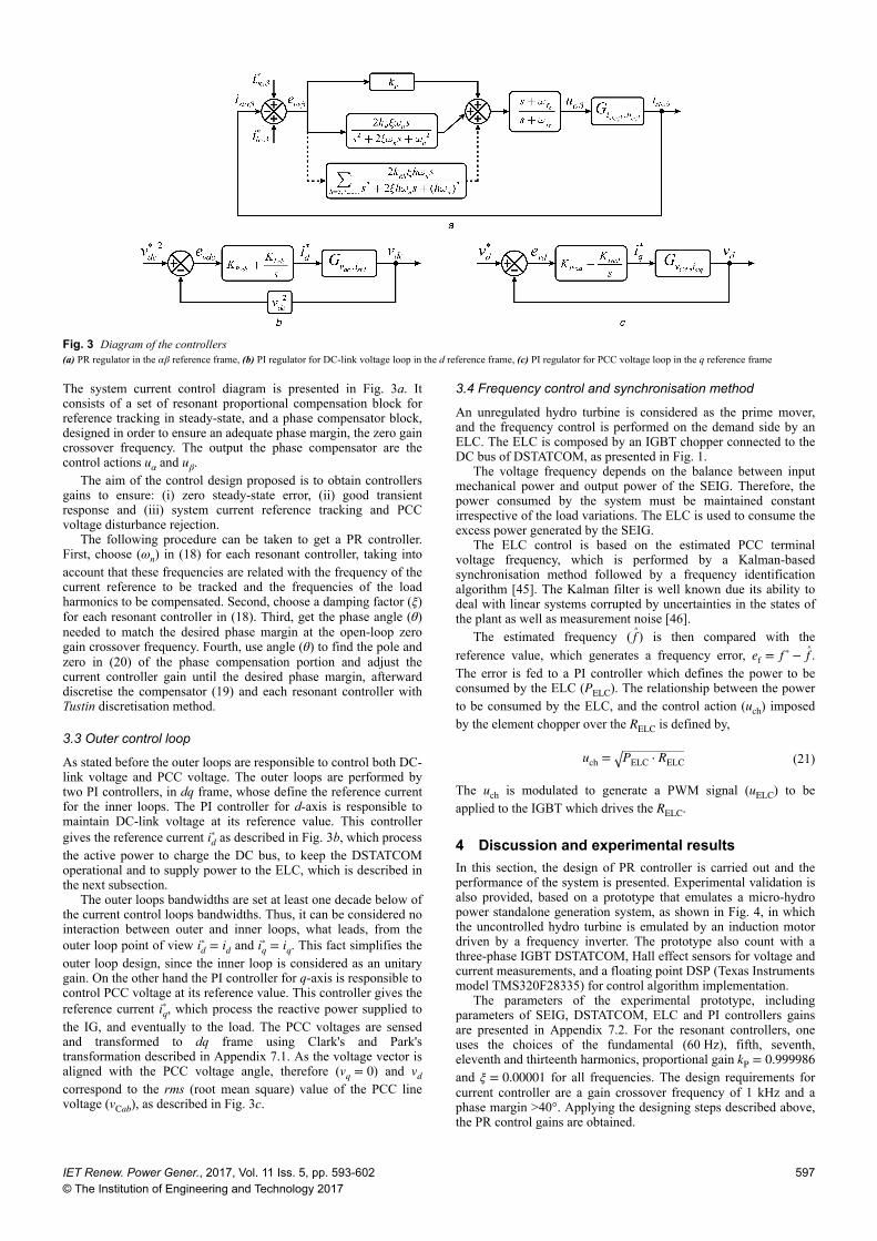
The satisfactory dynamic performance of DSTATCOM can beseen from Fig. 9 which gives the behaviour about some variablesof the micro-hydro power system during the application andremoval of sequential loads with different characteristics. The firstgraph of Fig. 9 shows the active power of load applied. Two 1.8 kW linear three-phase loads are connected in sequence, at 1 and 3 s, after that, both resistances are thrown off at 5 s. At 7 and 9 soccur the non-linear load application and removal, respectively,with active power equal 3.56 kW.
Moreover, Fig. 9 shows the rms value of PCC line voltage(vrms), the estimated frequency of PCC voltages ( f
^), the DC-bus
Fig. 6 Experimental results of the response of inner and outer loops controllers to changes in the references. In grey (dashed) the references variable and inblack (solid) the measures variable(a) ivα
∗ and istα, (b) ivβ∗ and istβ, (c) vd
∗ and vd, (d) vdc∗ and vdc
Fig. 7 Steady-state performance of micro-hydro power system under balanced non-linear load(a)–(c) vCab with iga, ila and ista, (d) Pload along with vCab and ila
Fig. 8 Steady-state performance of micro-hydro power system under balanced non-linear load(a)–(d) vCab, vCbc, iga and ila harmonic spectra
IET Renew. Power Gener., 2017, Vol. 11 Iss. 5, pp. 593-602© The Institution of Engineering and Technology 2017
599
voltage (vdc) and the behaviour of control's variables that keep thebalance active and reactive power of the system, id
∗ and iq∗,
respectively. When the load is applied on system, at instant 1, 3 and7 s, a small dip in vrms and f
^ can be observed, however, the voltage
and the frequency are regulated well and found to be stable. Theopposite behaviour occur with the vdc, a small rise in the DC-busvoltage happens, due to the ELC action for frequency control byconsumption of active power in excess of the system. This effectcan be observed by a negative reference current id
∗ , which processthe active power to charge the DC bus and to supply power to theELC. The reactive power required by the system can be observedacross reference current iq
∗, that keeps the excitation of IG andconsequently the PCC voltages regulated.
By the similar way, the performance under load removal can beanalysed, at instant 5 and 9 s, from Fig. 9. The sudden removal ofconsumer load causes on PCC voltage and frequency a small rise,however, a fast recovery of controller gains can be noticed andquickly they are kept within the limits. Through id
∗ can be noticedthat auxiliary load by ELC started consuming more power,ensuring the frequency and DC-link voltage regulation. The goodresponse of PI controllers together with PR control during transientconditions can be observed in the reference currents id
∗ and iq∗, it
gives the fast dynamic response for PCC voltage and DC-linkvoltage, besides it gives zero error during all steady-stateconditions.
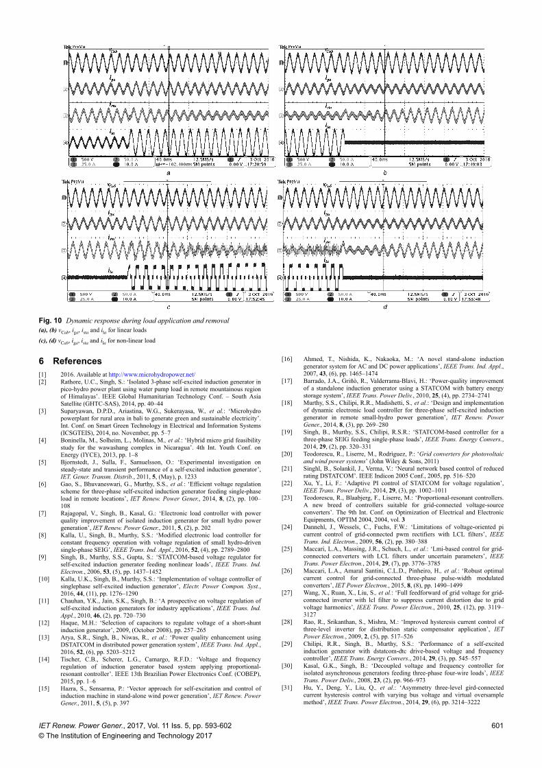
For a better analysis of the transient response in Fig. 9, Fig. 10presents by a detailed way form the waveforms of PCC voltage(vCab), SEIG current (iga), DSTATCOM current (ista) and loadcurrent (ila) of ‘a’ phase under loads step. Fig. 10a shows thevariables behaviour, at instant 3 s, when occur a step change of twothree-phase linear load, both with active power equal 1.8 kW. It isobserved that the peak voltages decrease instantly on the loadapplication, but these are well regulated in steady-state condition.The sudden removal of two loads that occur at 5 s, is presented inFig. 10b, in which an instantly increases can be observed on PCCvoltage.
Figs. 10c and d, presents the PCC voltage and currents of thesystem under the connection and removal of a non-linear loadcomposed by 3.56 kW three-phase load at 7 and 9 s, respectively.Can be verified a sudden change in load magnitude and shape, theDSTATCOM current is react immediately to keep the SEIG currentand PCC voltage sinusoidal.
5 ConclusionsThis paper presented a control system for voltage regulationapplied in a standalone micro-hydro power generation systembased on SEIG. For such regulation is proposed the design of a PRcontroller for currents control loop, in association with PIscontrollers for voltages control loop. Terminal voltages quality isas well improved by the frequency regulation which is achieved byan ELC, composed by chopper element and auxiliary loadconnected in DC-link of DSTATCOM. Experimental results arepresented, illustrating that the PR can ensure good tracking ofreference and rejection of disturbances. Moreover, an experimentalvalidation is carried out, showing that the closed-loop system withthe PR controller tracks efficiently a sinusoidal pattern forDSTATCOM currents, with changes in phase and amplitude. Theexperimental results have presented effective and satisfactoryvoltage and frequency control under steady-state and dynamicconditions for distinct loads. In addition, the quality of the SEIGcurrent and PCC voltage are corroborated by means of an analysisof THD and harmonic components that proves the system outputcomplies with requirements of the IEEE-519 standard when thereare non-linear loads connected.
Fig. 9 Dynamic response during loads application and removal
600 IET Renew. Power Gener., 2017, Vol. 11 Iss. 5, pp. 593-602© The Institution of Engineering and Technology 2017
6 References[1] 2016. Available at http://www.microhydropower.net/[2] Rathore, U.C., Singh, S.: ‘Isolated 3-phase self-excited induction generator in
pico-hydro power plant using water pump load in remote mountainous regionof Himalayas’. IEEE Global Humanitarian Technology Conf. – South AsiaSatellite (GHTC-SAS), 2014, pp. 40–44
[3] Suparyawan, D.P.D., Ariastina, W.G., Sukerayasa, W., et al.: ‘Microhydropowerplant for rural area in bali to generate green and sustainable electricity’.Int. Conf. on Smart Green Technology in Electrical and Information Systems(ICSGTEIS), 2014, no. November, pp. 5–7
[4] Boninella, M., Solheim, L., Molinas, M., et al.: ‘Hybrid micro grid feasibilitystudy for the wawashang complex in Nicaragua’. 4th Int. Youth Conf. onEnergy (IYCE), 2013, pp. 1–8
[5] Bjornstedt, J., Sulla, F., Samuelsson, O.: ‘Experimental investigation onsteady-state and transient performance of a self-excited induction generator’,IET. Gener. Transm. Distrib., 2011, 5, (May), p. 1233
[6] Gao, S., Bhuvaneswari, G., Murthy, S.S., et al.: ‘Efficient voltage regulationscheme for three-phase self-excited induction generator feeding single-phaseload in remote locations’, IET Renew. Power Gener., 2014, 8, (2), pp. 100–108
[7] Rajagopal, V., Singh, B., Kasal, G.: ‘Electronic load controller with powerquality improvement of isolated induction generator for small hydro powergeneration’, IET Renew. Power Gener., 2011, 5, (2), p. 202
[8] Kalla, U., Singh, B., Murthy, S.S.: ‘Modified electronic load controller forconstant frequency operation with voltage regulation of small hydro-drivensingle-phase SEIG’, IEEE Trans. Ind. Appl., 2016, 52, (4), pp. 2789–2800
[9] Singh, B., Murthy, S.S., Gupta, S.: ‘STATCOM-based voltage regulator forself-excited induction generator feeding nonlinear loads’, IEEE Trans. Ind.Electron., 2006, 53, (5), pp. 1437–1452
[10] Kalla, U.K., Singh, B., Murthy, S.S.: ‘Implementation of voltage controller ofsinglephase self-excited induction generator’, Electr. Power Compon. Syst.,2016, 44, (11), pp. 1276–1290
[11] Chauhan, Y.K., Jain, S.K., Singh, B.: ‘A prospective on voltage regulation ofself-excited induction generators for industry applications’, IEEE Trans. Ind.Appl., 2010, 46, (2), pp. 720–730
[12] Haque, M.H.: ‘Selection of capacitors to regulate voltage of a short-shuntinduction generator’, 2009, (October 2008), pp. 257–265
[13] Arya, S.R., Singh, B., Niwas, R., et al.: ‘Power quality enhancement usingDSTATCOM in distributed power generation system’, IEEE Trans. Ind. Appl.,2016, 52, (6), pp. 5203–5212
[14] Tischer, C.B., Scherer, L.G., Camargo, R.F.D.: ‘Voltage and frequencyregulation of induction generator based system applying proportional-resonant controller’. IEEE 13th Brazilian Power Electronics Conf. (COBEP),2015, pp. 1–6
[15] Hazra, S., Sensarma, P.: ‘Vector approach for self-excitation and control ofinduction machine in stand-alone wind power generation’, IET Renew. PowerGener., 2011, 5, (5), p. 397
[16] Ahmed, T., Nishida, K., Nakaoka, M.: ‘A novel stand-alone inductiongenerator system for AC and DC power applications’, IEEE Trans. Ind. Appl.,2007, 43, (6), pp. 1465–1474
[17] Barrado, J.A., Griñò, R., Valderrama-Blavi, H.: ‘Power-quality improvementof a standalone induction generator using a STATCOM with battery energystorage system’, IEEE Trans. Power Deliv., 2010, 25, (4), pp. 2734–2741
[18] Murthy, S.S., Chilipi, R.R., Madishetti, S., et al.: ‘Design and implementationof dynamic electronic load controller for three-phase self-excited inductiongenerator in remote small-hydro power generation’, IET Renew. PowerGener., 2014, 8, (3), pp. 269–280
[19] Singh, B., Murthy, S.S., Chilipi, R.S.R.: ‘STATCOM-based controller for athree-phase SEIG feeding single-phase loads’, IEEE Trans. Energy Convers.,2014, 29, (2), pp. 320–331
[20] Teodorescu, R., Liserre, M., Rodrìguez, P.: ‘Grid converters for photovoltaicand wind power systems’ (John Wiley & Sons, 2011)
[21] Singhl, B., Solankil, J., Verma, V.: ‘Neural network based control of reducedrating DSTATCOM’. IEEE Indicon 2005 Conf., 2005, pp. 516–520
[22] Xu, Y., Li, F.: ‘Adaptive PI control of STATCOM for voltage regulation’,IEEE Trans. Power Deliv., 2014, 29, (3), pp. 1002–1011
[23] Teodorescu, R., Blaabjerg, F., Liserre, M.: ‘Proportional-resonant controllers.A new breed of controllers suitable for grid-connected voltage-sourceconverters’. The 9th Int. Conf. on Optimization of Electrical and ElectronicEquipments, OPTIM 2004, 2004, vol. 3
[24] Dannehl, J., Wessels, C., Fuchs, F.W.: ‘Limitations of voltage-oriented picurrent control of grid-connected pwm rectifiers with LCL filters’, IEEETrans. Ind. Electron., 2009, 56, (2), pp. 380–388
[25] Maccari, L.A., Massing, J.R., Schuch, L., et al.: ‘Lmi-based control for grid-connected converters with LCL filters under uncertain parameters’, IEEETrans. Power Electron., 2014, 29, (7), pp. 3776–3785
[26] Maccari, L.A., Amaral Santini, C.L.D., Pinheiro, H., et al.: ‘Robust optimalcurrent control for grid-connected three-phase pulse-width modulatedconverters’, IET Power Electron., 2015, 8, (8), pp. 1490–1499
[27] Wang, X., Ruan, X., Liu, S., et al.: ‘Full feedforward of grid voltage for grid-connected inverter with lcl filter to suppress current distortion due to gridvoltage harmonics’, IEEE Trans. Power Electron., 2010, 25, (12), pp. 3119–3127
[28] Rao, R., Srikanthan, S., Mishra, M.: ‘Improved hysteresis current control ofthree-level inverter for distribution static compensator application’, IETPower Electron., 2009, 2, (5), pp. 517–526
[29] Chilipi, R.R., Singh, B., Murthy, S.S.: ‘Performance of a self-excitedinduction generator with dstatcom-dtc drive-based voltage and frequencycontroller’, IEEE Trans. Energy Convers., 2014, 29, (3), pp. 545–557
[30] Kasal, G.K., Singh, B.: ‘Decoupled voltage and frequency controller forisolated asynchronous generators feeding three-phase four-wire loads’, IEEETrans. Power Deliv., 2008, 23, (2), pp. 966–973
[31] Hu, Y., Deng, Y., Liu, Q., et al.: ‘Asymmetry three-level gird-connectedcurrent hysteresis control with varying bus voltage and virtual oversamplemethod’, IEEE Trans. Power Electron., 2014, 29, (6), pp. 3214–3222
Fig. 10 Dynamic response during load application and removal(a), (b) vCab, iga, ista and ila for linear loads
(c), (d) vCab, iga, ista and ila for non-linear load
IET Renew. Power Gener., 2017, Vol. 11 Iss. 5, pp. 593-602© The Institution of Engineering and Technology 2017
601

[32] Chauhan, Y.K., Jain, S.K., Singh, B.: ‘Operating performance of static seriescompensated three-phase self-excited induction generator’, Int. Journal ofElectrical Power and Energy Systems, 2013, 49, pp. 137–148
[33] Sekhar, V., Kant, K., Singh, B.: ‘DSTATCOM supported induction generatorfor improving power quality’, IET Renew. Power Gener., 2016, 10, (4), pp.495–503
[34] Yepes, A.G., Freijedo, F.D., López, Ó., et al.: ‘Analysis and design ofresonant current controllers for voltage-source converters by means of nyquistdiagrams and sensitivity function’, IEEE Trans. Ind. Electron., 2011, 58, (11),pp. 5231–5250
[35] Zmood, D.N., Holmes, D.G.: ‘Stationary frame current regulation of PWMinverters with zero steady-state error’, IEEE Trans. Power Electron., 2003,18, (3), pp. 814–822
[36] Liserre, M., Teodorescu, R., Blaabjerg, F.: ‘Multiple harmonics control forthree-phase grid converter systems with the use of PI-RES current controllerin a rotating frame’, IEEE Trans. Power Electron., 2006, 21, (3), pp. 836–841
[37] Yepes, A.G., Freijedo, F.D., Doval-Gandoy, J., et al.: ‘Effects of discretizationmethods on the performance of resonant controllers’, IEEE Trans. PowerElectron., 2010, 25, (7), pp. 1692–1712
[38] Bansal, R.C.: ‘Three-phase self-excited induction generators: an overview’,IEEE Trans. Energy Convers., 2005, 20, (2), pp. 292–299
[39] Kalla, U.K., Singh, B., Murthy, S.S.: ‘Adaptive noise suppression filter basedintegrated voltage and frequency controller for two-winding single-phase self-excited induction generator’, IET Renew. Power Gener., 2014, (August 2013),8(8), pp. 827–837
[40] Ieee, S.M.: ‘IEEE recommended practices and requirements for harmoniccontrol in electrical power systems – IEEE Std 519’ (Institute of Electricaland Electronics Engine Ehxtronics Engineers, New York, USA, 2014)
[41] Krause, P.C., Wasynczuk, O., Sudhoff, S.D., et al.: ‘Analysis of electricmachinery and drive systems’, 2013
[42] Ryan, M., Lorenz, R., De Doncker, R.: ‘Modeling of sinewave inverters: ageometric approach’. IECON ‘98. Proc. of the 24th Annual Conf. of the IEEEIndustrial Electronics Society (Cat. No.98CH36200), 1998, vol. 1, pp. 396–401
[43] Yuan, X., Allmeling, J., Merk, W., et al.: ‘Stationary frame generalizedintegrators for current control of active power filters with zero steady stateerror for current harmonics of concern under unbalanced and distortedoperation conditions’, IEEE Transactions, 2000, 38(2), pp. 2143–2150
[44] Erickson, R.W., Maksimovic, D.: ‘Fundamentals of power electronics’(Kluwer Academics Publishers, Colorado, 2001, 2nd edn.)
[45] Scherer, L.G., Tambara, R.V., de Camargo, R.F.: ‘Voltage and frequencyregulation of standalone self-excited induction generator for micro-hydropower generation using discrete time adaptive control’, IET Renew. PowerGener., 2016, 10, (4), pp. 531–540
[46] Cardoso, R., de Camargo, R., Pinheiro, H., et al.: ‘Kalman filter basedsynchronization methods’, IET. Gener. Transm. Distrib., 2008, 2, (4), p. 542
7 Appendices 7.1 Transformation matrices
va
vb
vc
=−1 1 00 −1 11 1 1
−1 vab
vbc
0(24)
xα
xβ
x0
= 23
1 −1/2 −1/20 3/2 − 3/2
1/ 2 1/ 2 1/ 2
xa
xb
xc
(25)
xd
xq
x0
=cos(θv) sin(θv) 0
−sin(θv) cos(θv) 00 0 1
xα
xβ
x0
(26)
xα
xβ
x0
=cos(θv) −sin(θv) 0sin(θv) cos(θv) 0
0 0 1
xd
xq
x0
(27)
7.2 System parameters
7.2.1 Self-excited induction generator: 3.7 kW, 220 V, 60 HZ,Δ-connected, four pole; Rs = 3.0 Ω, Rr′ = 1.0 Ω, Ls = 7.73 mH,Lr′ = 7.73 mH, Lm = 175.73 mH, at rated voltage; Rg = 3.8 Ω,Lg = 7.8 mH; Excitation capacitor bank: C = 40 μF (each), Δ -connected; Load resistance: RL = 39 Ω.
7.2.2 DSTATCOM parameters: Three-legs IGBT – VSI;Lf = 2.5 mH, Rf = 0.03 Ω; IGBT module: SKM75GB128D; DCbus capacitance/voltage: Cdc = 4700 μF/450 V.
7.2.3 Load parameters: Non-linear load: three-phase full bridgeuncontrolled rectifier with R = 22 Ω and L = 64 mH; Linear loads:1.8 kW + 1.8 kW.
7.2.4 Digital signal processor: Texas Instruments Inc. DSPTMS320F28335, floating point.
7.2.5 PI controllers gains: DC-link voltage PI controller:KPvdc = − 1.4391, KIvdc = 0.9994; PCC voltage PI controller:KPvd = − 0.9571, KIvd = 0.9987; Frequency PI controller:KPf = − 0.4182, KIf = 0.999.
7.2.6 Devices to results record: Power analyses (‘Fluke’ 43B);Four-channel digital storage oscilloscope (Agilent Technologymake).
602 IET Renew. Power Gener., 2017, Vol. 11 Iss. 5, pp. 593-602© The Institution of Engineering and Technology 2017