micro-electro-flow reactor ( -efr) system for ultra-fast ... · bhushan mahajan, 1, , taufiqueahmed...
TRANSCRIPT

Supporting Information
Micro-Electro-Flow Reactor (-EFR) System for Ultra-Fast Arene
Synthesis, and Manufacturing of Daclatasvir
Bhushan Mahajan, 1,, Taufiqueahmed Mujawar,1, Subhash Ghosh, Srihari Pabbaraja,
Ajay K. Singh
Division of Organic Synthesis and Process Chemistry,
CSIR-Indian Institute of Chemical Technology, Hyderabad-500007, India.
[] Academy of Scientific and Innovative Research (AcSIR), CSIR-Human Resource
Development Centre (CSIR-HRDC) Campus, Ghaziabad 201002, Uttar Pradesh, India
E-mail: [email protected]; [email protected];
[+] These authors contributed equally to this work.
Electronic Supplementary Material (ESI) for Chemical Communications.This journal is © The Royal Society of Chemistry 2019

S2
Table of contents: 1. General
1.1. Material and method used in experiments.
1.2. Measurement method.
S3
2. General reaction procedure and fabrication of micro-electrolysis
flow reactor (µ-EFR).
2.1. Micro-patterned nanoparticle deposited anode preparation.
2.1.1. Ni@Cu anode preparation.
2.1.2. Pt@Ni@Cu anode preparation.
2.2. Fabrication of µ-EFR.
S4
3. 3. General procedure for the synthesis of core biphenyl and DCV
API:
3.1. Integrated continuous micro-flow platform for the synthesis,
extraction and separation of core-biphenyl.
3.1.1. Optimization of-EFR platform for synthesis of symmetrical
arenes.
3.1.2. Optimization of micro-separator platform for extraction and
separation of symmetrical arenes.
3.1.3. Procedure for synthesis, extraction and separation of
symmetrical arenes.
3.1.4. Procedure for synthesis, extraction and separation of
symmetrical arenes with unactivated para-substituted group.
S13
4 Continuous flow DCV synthesis.
4.1. New generation continuous flow DCV synthesis.
S25
5. Spectra S37
6. Supporting references S66

S3
1. General
1.1. Material and method used in experiments
Most of the reagents and chemicals are bought from Spectrochem, AVRA and Sigma-
Aldrich, which were used as such without any further purification. Common organic
chemicals and salts were purchased from AVRA chemicals, India. Water used was
deionized water (18.2 mS conductivity) in the experiments. All work-up and purification
procedures were carried out with reagent-grade solvents. Analytical thin-layer
chromatography (TLC) was performed using analytical chromatography silica gel 60
F254 pre-coated plates (0.25 mm). The developed chromatogram was analysed by UV
lamp (254 nm). PTFE (id = 100-1000 μm) tubing, T-junction and back-pressure
controller (BPR) were procured from Upchurch IDEX HEALTH & SCIENCE. HPLC
Pump used was from KNAUER. SS318 capillary bought from the spectrum market,
Mumbai, India. Heating reactor used was from the Thales Nano Nanotechnology, Inc.
1.2. Measurement method.
Nuclear magnetic resonance (NMR) spectra were recorded on a Bruker 600, 500, 400
or 300 MHz in CDCl3 or DMSO-d6 solvent. Chemical shifts for 1H NMR are expressed
in parts per million (ppm) relative to tetramethylsilane (δ 0.00 ppm). Chemical shifts for
13C NMR are expressed in ppm relative to CDCl3 (δ 77.0 ppm). Data are reported as
follows: chemical shift, multiplicity (s = singlet, d = doublet, dd = doublet of doublets, t =
triplet, q = quartet, quin = quintet, sext = sextet, m = multiplet), coupling constant (Hz),
and integration. For scanning electron microscopy (SEM), gold sputter coating was
carried out on desired samples at pressure ranging in between 1 and 0.1 Pa. Sample
was loaded in the chamber of JSM-7610F and recorded by operating at 10-2 to 10-3 Pa
with EHT 15.00 kV with 300 V collector bias. LC-MS was conducted on Shimadzu
technology LCMS-8040 instrument equipped with LUNA C8 (250 4.6mm, 5.0u) and in

S4
build triple quadrupole detector. GC/MS analysis was conducted on Shimadzu
technology GCMS-QP2010 instrument equipped with a HP-5 column (30 m × 0.25 mm,
Hewlett-Packard) and inbuilt MS 5975C VL MSD system with triple axis detector.
Sonication (Power Sonic 405) was used for washing the metal surface. ATR analysis
was conducted on Portable FTIR spectrometer Bruker ALPHA. High-resolution mass
spectra (HRMS) were obtained from a JMS-T100TD instrument (DART) and Thermo
Fisher Scientific Exactive (APCI). Datalog model DCS-PS-6401 power supply system
was used to supply the constant current. Han’s Yueming laser series (model CMA0604-
B-A, Carbon dioxide based, laser power 60W) equipment was used for the fabrication
of micro-channel.
2. General reaction procedure and fabrication of micro-electrolysis flow reactor
(µ-EFR).
2.1. Micro-patterned nanoparticle deposited anode preparation:
Micro electro-flow outer body was fabricated with a stainless-steel body Fig. S1, (: 60
mm length x 60 mm width x 10 mm thickness). The second layer was fabricated with
teflon (60 mm length x 60 mm width x 1 mm thickness) layer made with laser cutter for
protecting the stainless steel from the corrosive acid base and insulator for the current
flow. Next, graphite cathode was customized as per the reactor size (60 mm length x
60 mm width x 2 mm thickness). For the solution flow under the constant current, third
layer consisted of a laser cutted teflon plastic (60 mm x 60 mm x 1 mm thickness) zig-
zag groove with rectangular shape (2 mm x 80.0 mm). Another copper electrode was
customized as per the reactor size (60 mm length x 60 mm width x 2 mm thickness).
After fabrication of each layer and to align the patterns, the 4-corners of each two teflon
film were drilled to make a hole (1 mm diameter). Thereafter, both the electrodes were
sandwiched by teflon zig-zag channel sheets with identical dimension to fit groove

S5
channels and coupled to each other by inserting metal pins through the holes at the film
corners (Fig. S1).
2.1.1. Ni@Cu anode preparation: Ni nanoparticles were patterned over copper plate
made by electrodeposition method.S1 In this method, copper plate was cleaned by 2N
acetic acid, followed by deionized water to remove oxidized layer and dried by N2 flow.
Then, the copper plate was sandwiched between the designed reactor and connected
with pump (Fig. S1). Copper plate was connected with negative charge and graphite
plate was connected with positive charge. Aqueous solution of Ni.acetate.H2O (0.125
wt.%) was passed through the microreactor channel with flow rate of 100 µL min−1 at
2V for 2 h, which typically led to the generation of an ash colored pattern, and then
washed with water thoroughly to remove any unreacted salt and nanoparticle (Fig. S2
and S3).
Fig. S1. Schematic diagram of continuous flow micro-patterned nickel nano-particle
generation over the copper support.

S6
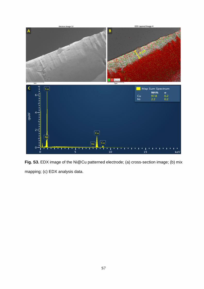
Fig. S2. Scanning Electron Microscopic, EDX and elemental mapping analysis of the Ni@Cu patterned electrode; (a) original image;
(b) low resolution image; (c) high-resolution image; (d) high-resolution mix mapping of electrode; (e) EDX analysis data; (f) low
resolution mix mapping at interface between Cu and Ni; (g) Cu elemental mapping; (h) Ni elemental mapping.
S7
Fig. S3. EDX image of the Ni@Cu patterned electrode; (a) cross-section image; (b) mix
mapping; (c) EDX analysis data.

S8
2.1.2. Pt@Ni@Cu anode preparation: Modified phosphates bath-based method has
been used for deposition of Pt over the Ni@Cu pre-deposited anode. 2 In this method,
stock electrolytic solution containing mixture of Pt(IV) chlorides 150 mg, diammonium
hydrogen phosphate (NH4)2HPO4 80 mg, disodium hydrogen phosphate (Na)2HPO4 200
mg, ammonium chloride 50 mg, and water 10 mL, was pumped with fix flow rate of 100
L min−1 for 2h at 70 oC under current density of 0.3 A/dm2, which typically led to the
generation of a black colored patterning, and then washed with water thoroughly to
remove any unreacted salt and nanoparticle (Fig. S5). Flower shape pattern morphology
was confirmed by SEM/EDX (Fig.S5, S6).
Fig. S4. Schematic diagram of continuous flow micro-patterned Pt nano-particle
generation over the Ni@Cu anode.

S9
Fig. S5 Micro-electro flow reactor. (a) schematic illustration of fabrication of Micro-
electro flow reactor; Step 1: patterning of Ni over the copper plate. Step 2: preparation
of Pt nano-flower deposition over the Ni@Cu; Step 3: fabrication of laser grooved PFTE
channel. Step 4: fabrication of graphite electrode; Step 5: fabrication of metal protection
layer. Step 6: mannual screw tight micro-electro flow reactor, showing one inlet and
one outlets; (b) original image of the Pt@Ni@Cu micro-pattern electrode; (c&d) top
view: low and high resolution SEM image respectively; (e) EDX graph from top view, (f-
i) top view elemental Pt, Cu, Ni and mix mapping respectively; (j-h) cross-sectional mix
mapping elemental, Pt, Cu, and Ni respectively.

S10
Fig. S6. (A) Cross-sectional SEM of Pt@Ni@Cu, (B) EDX of cross-sectional of Pt@Ni@Cu electrode.

S11
2.2 Fabrication of -EFR: After the fabrication of nano-particle deposited electrode
through electro-deposition method, the electrode was cleaned by washing with water
under ultrasonic and dried. Polytetrafluoroethylene (PTFE) channel sandwiched by two
electrodes with matching dimension of microchannel were placed between metal holder,
the set was aligned by inserting metal pins through the holes at the film corners. Finally,
the metal holder was tightly pressed by screw to seal the device with no leak (Fig.S7).

S12
Fig. S7. Schematic presentation of micro-electro flow reactor; (A & B) original image and 3D model; () customized metal plate; ()
laser cutted PTFE film; () customized graphite electrode; () Laser cutted zig-zag PTFE channel; () Pt@Ni patterned structure.

S13
3. General procedure for the synthesis of core biphenyl and DCV API:
3.1. Integrated continuous micro-flow platform for the synthesis, extraction and
separation of core-biphenyl.
3.1.1. Optimization of-EFR platform for synthesis of symmetrical biphenyl:
We proceeded further by monitoring the model C-C coupling reaction of a solution containing
bromobenzene(1a)/ NiCl2.glyme/ bipyridine/ LiCl/ DMA, which was taken in the syringe and
connected with above designed -EFR as described in (Fig. S8) to synthesize biphenyl. The
solution, in a stoichiometric molar ratio of 10 (1a/ NiCl2.glyme), was passed through a EFR
(reactor volume 200 L) containing Ni@Cu anode and graphite cathode held at 25 °C with
current 4 mA at a flow rate of 50 L min−1 (residence time = 4 min), which typically led to the
generation of a brownish coloured solutions with 5% yield of the desired product 2a (Table
S1, entry 1). The use of various electrode combination of Ni/C, Ni foam/C, Cu/C, Pt/C, C/C,
and Pt@Ni@Cu furnished 2a (0–98%) (Table S1, entries 2–6). Notably, only the Pt@Ni@Cu
anode was found to be the best system suitable for the ultra-fast biphenyl generation reaction
(Table S1, entry 6). Assured of the feasibility of the -EFR with Pt@Ni@Cu anode system
for use in C-C coupling reaction, we next examined the solvent effect. The use of either
dimethylacetamide (DMA) or dimethylformamide (DMF) as a solvent led to complete
conversion and excellent selectivity within 4 min, whereas tetrahydrofuran (THF),
dimethylsulphoxide (DMSO), acetonitrile (MeCN), and water were not successful to produce
the product in desired yield. Ligand screening experiments shows that the inexpensive
combination of NiCl2·glyme and a bipyridyl ligand (L1) provides the most effective catalyst
system for the transformation on bromobenzene (Table S1, entries 12-19). Optimized micro-
electrolysis reaction conditions, 98% yield of 2a was obtained in 4.0 min of residence time at
S14
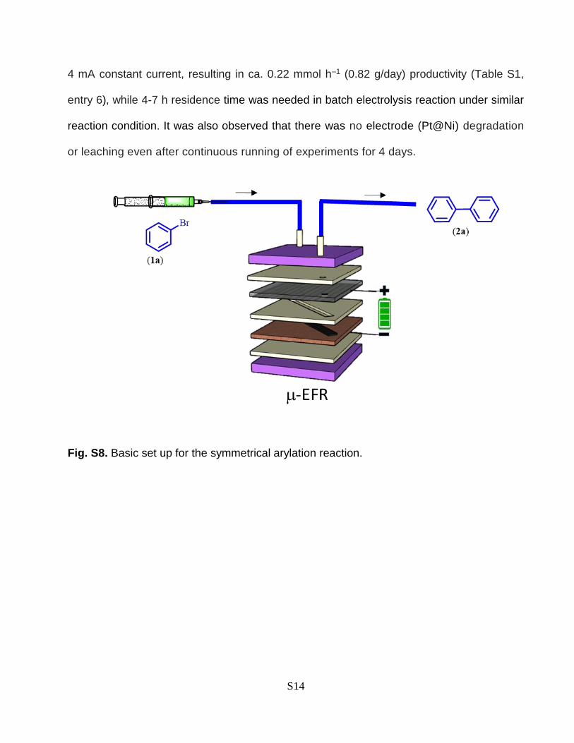
4 mA constant current, resulting in ca. 0.22 mmol h–1 (0.82 g/day) productivity (Table S1,
entry 6), while 4-7 h residence time was needed in batch electrolysis reaction under similar
reaction condition. It was also observed that there was no electrode (Pt@Ni) degradation
or leaching even after continuous running of experiments for 4 days.
Fig. S8. Basic set up for the symmetrical arylation reaction.

S15
Table S1. Evaluation of reaction optimization experiment with -EFR.
Conditions Entry Deviation from above % Yielde
Effect of Anode (-) (a) 1 Ni/C 05
2 Ni Foam/C 0
3 Cu/C 0
4 Pt/C Trace
5 C/C 0
6 Pt@Ni@Cu/C 98
Effect of solvent(b) 7 DMF 87
8 MeCN 5
9 THF Trace
10 DMSO 34
11 DMA/H2O (9:1) Trace
Effect of ligand(c) 12 L2 20
13 L3 Trace
14 L4 60
15 L5 Trace
19 NA No reaction
Retention time
(min.)(d)
17 1 73
18 2 77
19 10 98
20 0.5 25
Reaction condition: bromobenzene (0.15 mmol), NiCl2.glyme (10 mol%), bipyridine (L1, 10 mol%),
LiCl (4 eq.), DMA 0.01 M, current (4 mA), flow rate 50 L/min; (a) various anode; (b) anode
(Pt@Ni@Cu); (c) bipyridine replace with difference ligand (10 mol%), anode (Pt@Ni@Cu), (d) anode
(Pt@Ni@Cu), reaction time variation; (e) yield is based on GC-Mass analysis with anisole as internal
standard.

S16
3.1.2. Optimization of micro-separator platform for extraction and separation of
symmetrical arenes.
Fabrication of microseparator: As shown in (Fig. S9), laser ablation on PTFE film was
employed to fabricate the proposed dual channel device. The PTFE film layers of 1000 μm
thick were ablated by UV laser 355 nm, to form serpentine microchannel (1000 μm width,
1000 μm depth and 80 cm length) as per our previously reported procedure. 3 The 4-corners
of each film were drilled to make holes of1 mm diameter to align the film patterns. After laser
ablation, the films were cleaned by washing with DCM under ultrasonic and dried.
Polypropylene coated polytetrafluoroethylene (PTFE) membrane (Whatmann, 0.45 μm pore,
47 mm dia.) was sandwiched by two sheets of PTFE film with microchannel. The sandwich
was in turn covered by metal protecting PTFE films and covered by metal holder. All the
sheets were aligned by inserting metal pins through the holes at the film corners (Fig. S9).
Finally, the metal holder was tightly pressed by screw to seal the device with no leak.

S17
Fig. S9. Illustration of a fluoropolymer PTFE membrane based microseparator; (a) SS-metal
body; (b) metal protecting PTFE layer; (c) laser grooved PTFE channel; (d) propylene coated
PTFE membrane. (e) 3D model; (f) original photograph.

S18
Solvent exchange optimization: To switch the solvent containing product from DMA to low
volatile solvent DCM, the additional PTFE membrane embedded phase separator was
connected to the outlet of the -EFR reactor as shown in (Table S2). A serial process of
droplet formation, extraction and separation for purification of the symmetrical biaryls was
conducted in droplet microfluidics equipped with the PTFE membrane microseparator, as
explained in a stepwise manner. Step 1: At first, formation of alternating organic-aqueous
droplets by introducing water into the product mixture in DMA through X-junction. Secondly,
extraction of reaction wastes into aqueous stream by passing through a length of 0.5 m
capillary during 0.7 min. Step 2: Finally, complete separation of the mixture of reactant,
catalyst and product containing organic phase by wetting and crossing through thin
fluoropolymer membrane to the bottom of the separator, whereas the waste aq. DMA
containing aqueous phase did not wet the membrane and passed as the original stream
(Table S2).

S19
Table S2. Solvent exchange through the micro-separator.
Entry Flow rate (µL/min.) Extraction
time (min.)
Separation
time (min.)
Extracting
solvent
% Yield
Solvent Water 2a
1 50 500 0.65 0.33 DCM 98
2 20 500 0.68 0.35 DCM 97
3 100 500 0.65 0.33 DCM 95
4 100 100 2.2 1.2 DCM 41
5 50 500 0.65 0.33 Toluene 94
6 50 500 0.65 0.33 DEE 98
7 50 500 0.65 0.33 MTBP 98
Yields are based on GC-MS analysis using anisole as an internal standard; average of
two measurements.

S20
3.1.3. Procedure for the synthesis, extraction and separation of symmetrical
arenes.
Table S3: Comparative table of macro and integrated continuous micro-flow
electrolysis reaction for the C-C coupling reaction.
Entry Substrate (1) Product (2) [% yield in our study]/ (Comparative
result) ref.
1
1a
2a
[98]/
(Pd, 100 %, 100 oC, K2CO3 base, 24 h; 4
Pd/C, Zn, CO2, 91%, 15 hr) 5
2
1b 2b
[91]
3
1c
2c
[90]
4
1d
2d
[74]/
(Pd-PEOOSI-IPr, t-BuLi, 92%, 10 min) 6
5
1e
2e
[65]/(Pd-PEOOSI IPr, 62%, 1h) 7
6
1f
2f
[72]
7
1g
2g
[89]

S21
The stock solution containing a mixture of bromobenzene (1a) (15 mmol) and
NiCl2.glyme (10 mol%), 2,2'-bipyridine (10 mol%), LiCl (6 mmol) in 100 mL of DMA was
passed through the pre-designed µ-EFR, keeping 4 min. residence time and 4 mA
constant current. The reaction mixture was quenched, and solvent exchange was
achieved (from high boiling solvent DMA to low boiling solvent DCM by introducing water
and low boiling solvent (DCM) through additional X-mixer to form organic-aqueous
droplets (Table S3). Complete extraction between the organic-aqueous segments was
observed with 0.7 min retention time by flowing through a PTFE capillary (id = 1000 µm,
length = 0.5 m, vol. = 392 µL). Further, organic-aqueous segment was separated by
passing through the above designed homemade microseparator and complete
separation was achieved by regulating the back pressure with a retention time (0.3 min),
flow rate of water (500 µL/min) and flow rate of DCM (50 µL/min). The extracted waste
aqueous layer was further extracted with DCM and analyzed by GC-MS, which showed
no product and was also confirmed by the absence of the corresponding peaks in the
crude NMR analysis (1H and 13C NMR spectra). Under similar extracting conditions,
several other solvents were tested even for the replacement of DCM with diethyl ether,
toluene, MTBP solvent and could see that the results are encouraged. The extracting
solvent was removed under reduced pressure and the residue was purified by column
chromatography (hexane/ethyl acetate) to give the product 2a-2g.
Note: Distribution ratio is very important parameter for the liquid-liquid membrane based
extraction of the product. In optimized solvent distribution ratio, we need to use 1:10:1
ratio of DMA: Water: DCM.
S22
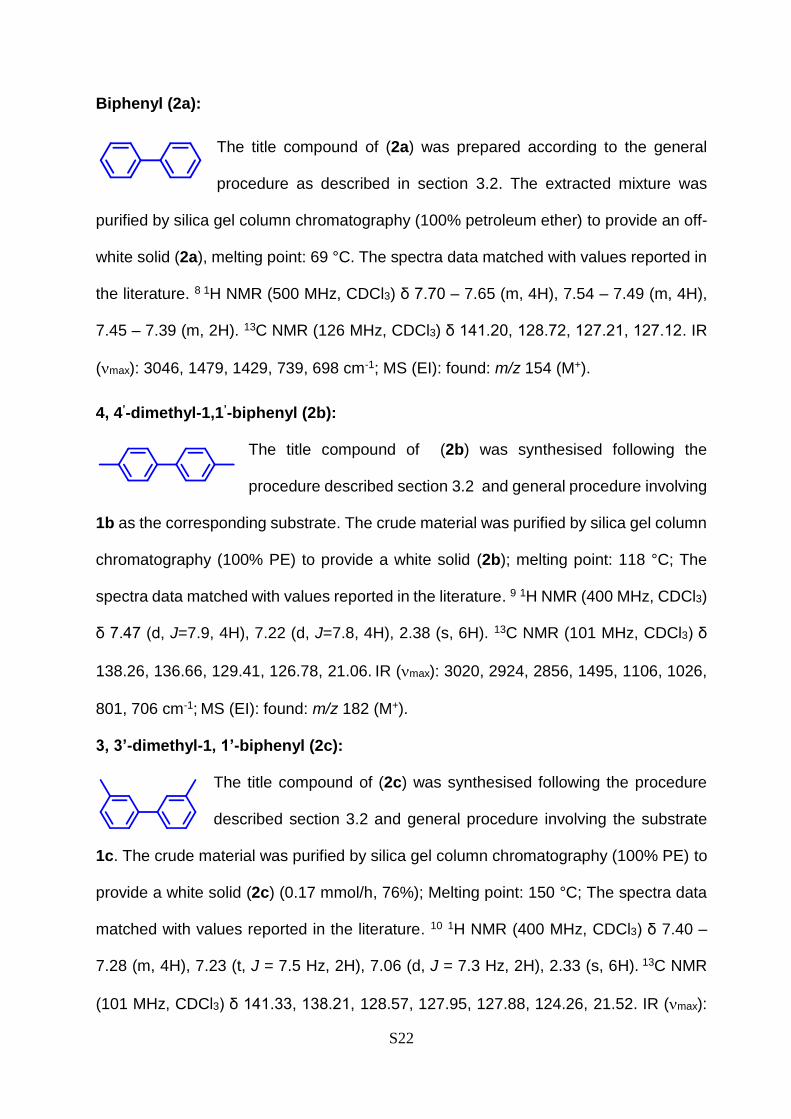
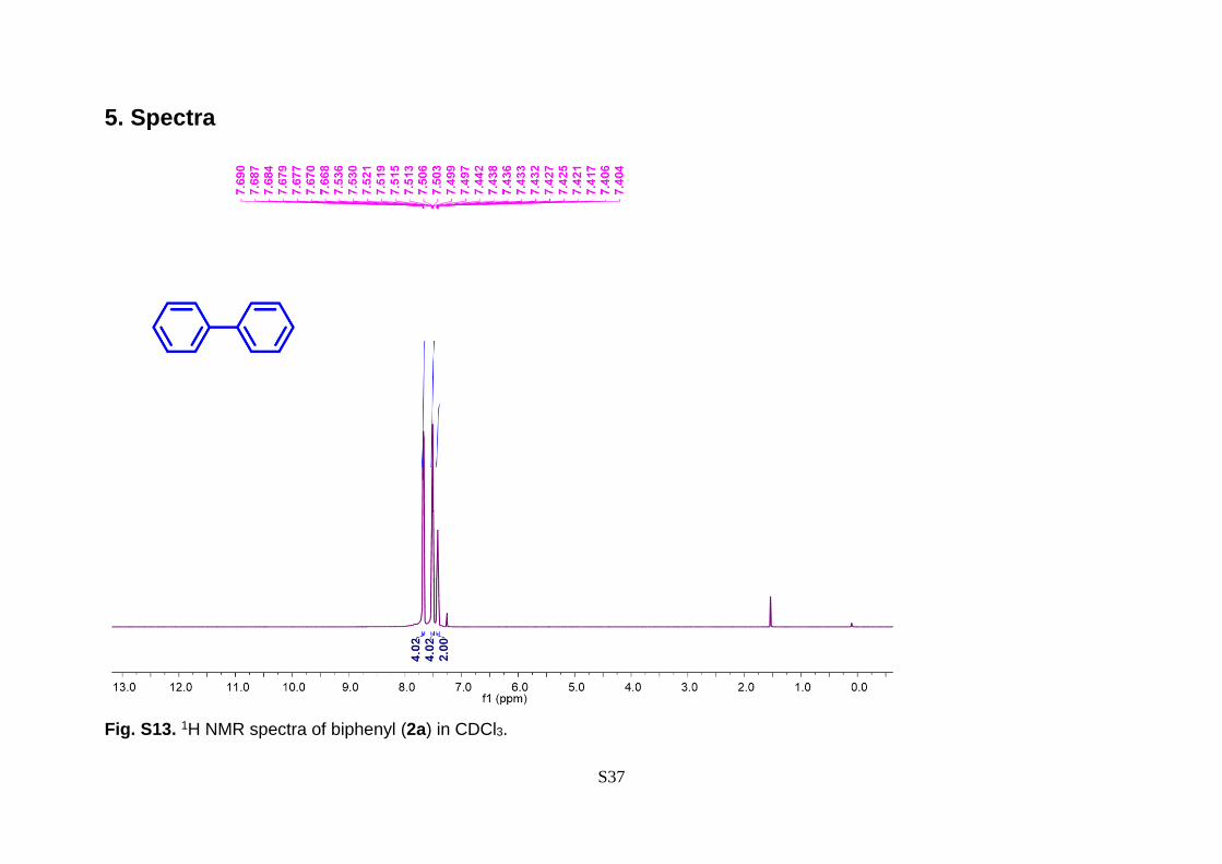
Biphenyl (2a):
The title compound of (2a) was prepared according to the general
procedure as described in section 3.2. The extracted mixture was
purified by silica gel column chromatography (100% petroleum ether) to provide an off-
white solid (2a), melting point: 69 °C. The spectra data matched with values reported in
the literature. 8 1H NMR (500 MHz, CDCl3) δ 7.70 – 7.65 (m, 4H), 7.54 – 7.49 (m, 4H),
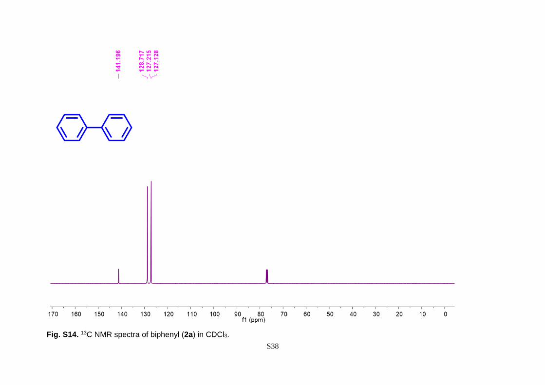
7.45 – 7.39 (m, 2H). 13C NMR (126 MHz, CDCl3) δ 141.20, 128.72, 127.21, 127.12. IR
(max): 3046, 1479, 1429, 739, 698 cm-1; MS (EI): found: m/z 154 (M+).
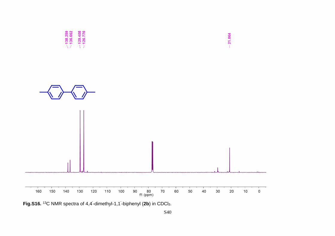
4, 4’-dimethyl-1,1’-biphenyl (2b):
The title compound of (2b) was synthesised following the
procedure described section 3.2 and general procedure involving
1b as the corresponding substrate. The crude material was purified by silica gel column
chromatography (100% PE) to provide a white solid (2b); melting point: 118 °C; The
spectra data matched with values reported in the literature. 9 1H NMR (400 MHz, CDCl3)
δ 7.47 (d, J=7.9, 4H), 7.22 (d, J=7.8, 4H), 2.38 (s, 6H). 13C NMR (101 MHz, CDCl3) δ
138.26, 136.66, 129.41, 126.78, 21.06. IR (max): 3020, 2924, 2856, 1495, 1106, 1026,
801, 706 cm-1; MS (EI): found: m/z 182 (M+).
3, 3’-dimethyl-1, 1’-biphenyl (2c):
The title compound of (2c) was synthesised following the procedure
described section 3.2 and general procedure involving the substrate
1c. The crude material was purified by silica gel column chromatography (100% PE) to
provide a white solid (2c) (0.17 mmol/h, 76%); Melting point: 150 °C; The spectra data
matched with values reported in the literature. 10 1H NMR (400 MHz, CDCl3) δ 7.40 –
7.28 (m, 4H), 7.23 (t, J = 7.5 Hz, 2H), 7.06 (d, J = 7.3 Hz, 2H), 2.33 (s, 6H). 13C NMR
(101 MHz, CDCl3) δ 141.33, 138.21, 128.57, 127.95, 127.88, 124.26, 21.52. IR (max):

S23
3021, 2924, 1600, 1472, 1216, 758, 708, 66. cm-1; MS (EI): found: m/z182 (M+).
1,1’ -binaphthalene (2d):
The title compound of (2d) was synthesised following the procedure
described section 3.2 and general procedure involving substrate (1d).
The crude material was purified by silica gel column chromatography
(100% PE) to provide a white solid (2d); Melting point: 159 °C. The spectra data
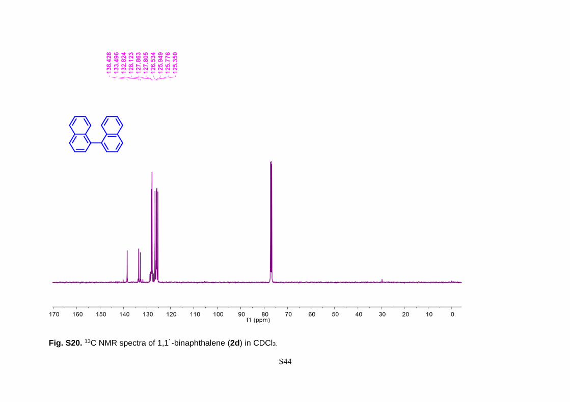
matched with values reported in the literature. 7 1H NMR (500 MHz, CDCl3) δ 7.92 (dd,
J = 26.7, 5.5 Hz, 4H), 7.66 – 7.55 (m, 2H), 7.54 – 7.43 (m, 4H), 7.40 (t, J = 12.7 Hz, 2H),
7.27 (t, J = 7.0 Hz, 2H). 13C NMR (101 MHz, CDCl3) δ 138.42, 133.49, 132.82, 128.12,
127.86, 127.80, 126.53, 125.94, 125.77, 125.35. IR (max): 3023, 1215, 740, 670 cm-1;
MS (EI): found: m/z 254.11 (M+).
2, 2’-binaphthalene (2e):
The title Compound of (2e) was synthesised following the
procedure described section 3.2 and general procedure
involving substrate (1e). The crude material was purified by silica gel column
chromatography 100% PE) to provide a white solid (2e) (0.16 mmol/h, 73%); Melting
point: 184 °C; the spectra data matched with values reported in the literature. 7 1H NMR
(400 MHz, CDCl3) δ 7.94 (d, J = 4.3 Hz, 4H), 7.58 (t, J = 7.4 Hz, 2H), 7.55 – 7.44 (m,
4H), 7.39 (d, J = 8.1 Hz, 2H), 7.26 (dd, J = 18.2, 11.1 Hz, 2H). 13C NMR (126 MHz,
CDCl3) δ 138.43, 133.49, 132.82, 128.12, 127.86, 127.80, 126.53, 125.95, 125.78,
125.35. IR (max): 3023, 1215, 741, 670 cm-1; MS (EI): found: m/z 254.11 (M+).

S24
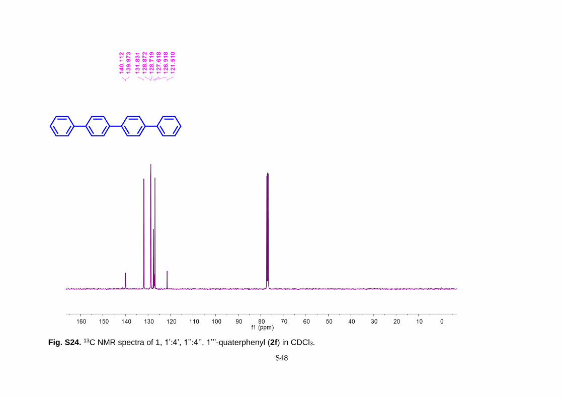
1, 1’:4’, 1’’:4’’, 1’’’-quaterphenyl (2f):
The title Compound of (2f) was synthesised following
the procedure described in Section 4.1 with substrate
(1f). The crude material was purified by silica gel column chromatography (100% PE)
to provide a white solid (2f) (0.16 mmol/h, 72%); Melting point: 298 °C. The spectra data
matched with values reported in the literature. 11 1H NMR (500 MHz, CDCl3) δ 7.61 –
7.55 (m, 8H), 7.47 – 7.43 (m, 8H), 7.38 (t, J = 7.3 Hz, 2H). 13C NMR (126 MHz, CDCl3)
δ 140.11, 139.97, 131.90, 128.86, 128.87, 127.68, 126.98, 121.57. IR (max): 3734,
3422, 3026, 2928, 1958, 1897, 1727, 1659, 1592, 1476, 1391, 1272, 1211, 1076, 1004,
828, 756, 693 cm-1; MS (EI): m/z 306.14 (M+).
1, 1’-([1, 1’-biphenyl]-4,4'-diyl) diethanone (2g):
Compound (2g) was synthesised following the procedure
described in Section 4.1 with substrate (1g). The crude
material was purified by silica gel column chromatography (hexane/ethyl acetate; 95:05)
to provide a white solid (2g); melting point: 148 °C; 1H NMR (400 MHz, CDCl3) δ 7.49 –
7.44 (m, 4H), 7.38 – 7.33 (m, 4H), 4.03 (td, J = 6.1, 4.2 Hz, 4H), 3.75 (td, J = 6.1, 4.2
Hz, 4H), 1.63 (s, 6H). 13C NMR (75 MHz, CDCl3) δ 142.44, 131.28, 127.13, 121.83,
108.41, 64.45, 27.49. IR (max): 3390, 2980, 2888, 1479, 1383, 1245, 1197, 1082, 1031,
876, 825 cm-1; MS (EI): m/z 326.15 (M+)

S25
4: Continuous flow DCV synthesis:
Scheme S1. First generation novel metal assisted DCV synthesis.12

S26
Scheme S2. Second generation batch protocols for the synthesis of DCV.13

S27
4.1. New generation continuous flow synthesis.
Step 1: Fridel-Craft acylation
A solution of compound 2a in DCE was charged in one syringe. 2-Chloroacetyl chloride,
various lewis acid (aluminum chloride, aluminum bromide, ferric chloride, tin chloride, or
stannic chloride) dissolved in DCE was charged in the capillary microreactor with a T-
mixer using separate syringe pumps (Fig.S10). The two solutions were introduced into a
T-mixer in a varied flow rate and ratio to maintain the stoichiometry, and then passed
through PTFE tubing for Friedel-Craft acylation reaction. Optimization conditions were
varied depending on the nature of the catalyst reagent, retention time, temperature, and
pressure etc (Table S4).

S28
Table S4. Optimization of continuous micro-flow reaction to synthesize daclatasvir intermediate 3 ultra-fast manner.
Entry Flow rate (L/min) Temperature
(oC)
Pressure
(bar)
Retention
time (min.)
Yield (%)
Compound 2a 2-chloro acetyl chloride 8m 8
1a 100 100 40 1 50 36 10
2a 100 100 40 5 50 44 20
3a 100 100 80 5 50 * *
4b 100 200 80 5 33.3 12 7
5b 100 250 80 5 28.6 0 98
Reaction condition: (a) 2a: 0.25 M in DCM; mixture of chloroacetyl chloride and Aluminum chloride (0.625 M in DCM with 1:1 molar
ratio); (b) 2a: 0.16 M in DCE; mixture of chloroacetyl chloride and Aluminum chloride (0.4 M in DCE with 1:1 molar ratio); Yields are
based on isolated yields; * represent the tube blocking problem was encountered.

S29
Figure S10. Schematic presentation of continuous micro-flow synthesis of daclatasvir
API (3).
A solution of 2a disolved in DCE (0.16 M) and charged in one syringe. In another syringe
filled with the solution of chloroacetyl chloride (0.4 M in DCE), and AlCl3 (1 equiv.)
(Fig.S10). The two solutions were introduced to a T-mixer in a flow rate with the ratio of
1: 6.25 (compound 2a: chloroacetyl chloride) to maintain the stoichiometry, and then
passed through a PTFE tubing (id = 1000 µm, l = 12.8 m, vol. = 10 ml) to occur the Friedel-
craft acylation during 28.6 min of residence time and 80 oC temperature and 5 bar
pressure (Table S4, entry 5). The resulting solution was quenching with cold water and
extracting through the regular process. 1H NMR (400 MHz, CDCl3) δ 8.14 – 8.04 (d, 4H),
7.84 – 7.73 (d, 4H), 4.74 (s, 4H).13C NMR (126 MHz, CDCl3) δ 190.66, 144.92, 133.85,
129.37, 127.80, 45.84. IR (max): 2992, 2935, 1692, 1601, 1555, 1399, 1308, 1214, 966,
808, 765, 642 cm-1; MS (EI): m/z 307.17 (M+).

S30
Step 2: Ester formation.
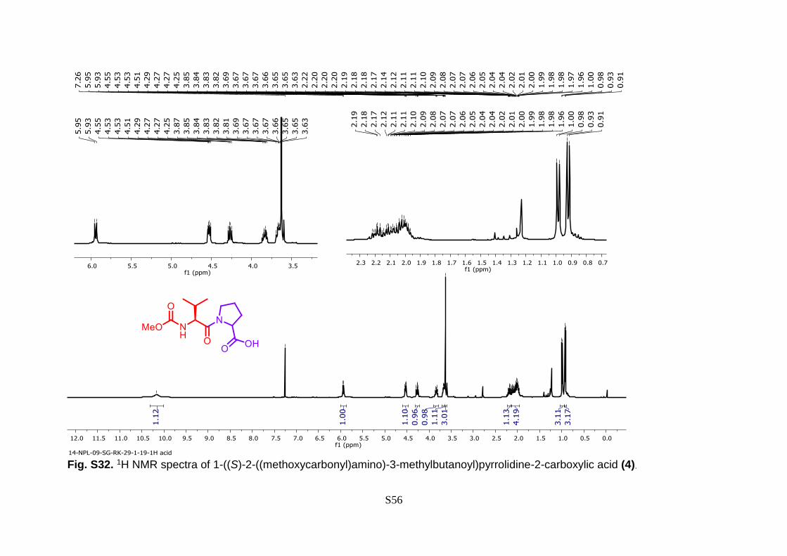
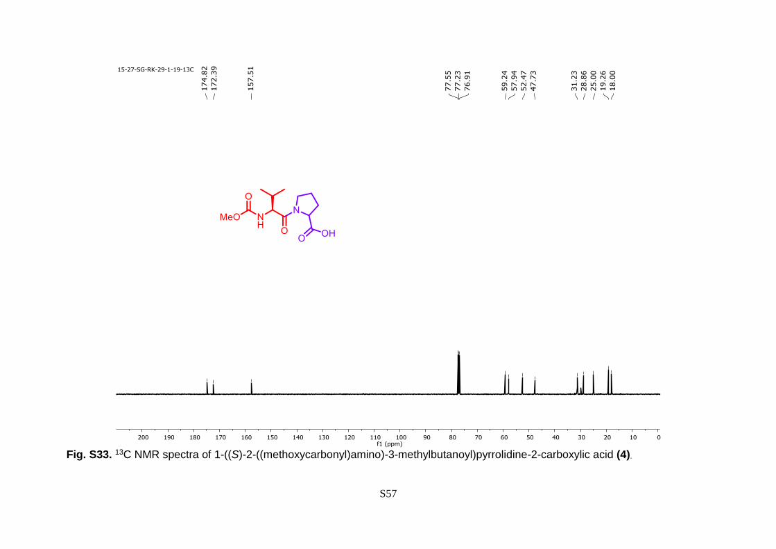
Reported batch method has been followed for the preparation of compound 4. 14 1H NMR
(400 MHz, CDCl3) δ 10.17 (s, 1H), 5.94 (d, J = 9.4 Hz, 1H), 4.53 (dd, J = 8.4, 4.5 Hz, 1H),
4.27 (dd, J = 9.3, 7.5 Hz, 1H), 3.84 (dt, J = 9.6, 6.9 Hz, 1H), 3.70 – 3.65 (m, 1H), 3.63 (s,
3H), 2.23 – 2.14 (m, 1H), 2.15 – 1.96 (m, 4H), 0.99 (d, J = 6.7 Hz, 3H), 0.92 (d, J = 6.7
Hz, 3H). 13C NMR (100 MHz, CDCl3) δ 174.82, 172.39, 157.51, 59.24, 57.94, 52.47,
47.73, 31.23, 28.86, 25.00, 19.26, 18.00.
A solution of compound 3 and 4 in MeCN was charged in one syringe and triethylamine
in DCE was taken in another syringe (Fig. S11). The two solutions were introduced into
a T-mixer in a varied flow rate and ratio to maintain the stoichiometry, and then passed
through PTFE tubing for Friedel-craft acylation reaction. Optimization conditions were
varied depending on the nature of the reagent, retention time, temperature, and pressure
etc (Table S5).

S31
Table S5. Optimization of continuous micro-flow reaction to synthesize daclatasvir intermediate API (5) in ultra-fast manner.
Entry Flow rate (mL/min) Temperature
(oC)
Pressure
(bar)
Retention
time (min.)
Yield (%)
Compound 3 + 4 TEA 10
1 2.5 2.5 80 5 2 99
2 3.0 2.0 80 5 2 99
3 3.5 1.5 80 5 2 99
4 4.0 1.0 50 5 2 43
Reaction condition: (a) Stock solution 3 (0.25M in MeCN) + 4 (0.5M in MeCN); TEA (1.3M in MeCN); Yields are based on isolated
yields.

S32
Fig. S11. Schematic presentation of continuous micro-flow synthesis of daclatasvir API
(5).
A reactant of 3 disolved in MeCN (0.25 M) and mix with 4 (0.5 in MeCN) charged in one
syringe. In another syringe filled with the solution of triethylamine (1.3 M in MeCN) (Fig.
S11). The two solutions were introduced to a T-mixer in a flow rate with the ratio of 1:
2.25 (compound 4: TEA) to maintain the stoichiometry, and then passed through a PTFE
tubing (id = 1000 µm, l = 12.8 m, vol. = 10 ml) for the ester formation during 2 min of
residence time and 80 oC temperature and 5 bar pressure (Table S5, entry 3). Under the
stable condition, product was collected in reservoir containing cold water and extracting
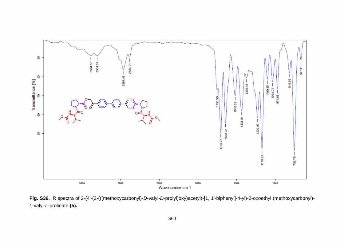
through the routine process. 1H NMR (500 MHz, CDCl3) 7.99 (t, J = 7.7 Hz, 2H), 7.72 (d,
J = 8.3 Hz, 2H), 5.56 (d, J = 16.4 Hz, 1H), 5.40 (d, J = 9.3 Hz, 1H), 5.26 (d, J = 16.4 Hz,
1H), 4.71 (dd, J = 8.2, 5.1 Hz, 1H), 4.37 – 4.26 (m, 1H), 3.86 – 3.79 (m, 1H), 3.75 – 3.63
(m, 4H), 2.35 (ddd, J = 12.8, 9.8, 5.7 Hz, 2H), 2.24 – 2.15 (m, 1H), 2.11 – 2.03 (m, 2H),
1.01 (t, J = 13.6 Hz, 3H), 0.94 (t, J = 8.7 Hz, 3H).13C NMR (101 MHz, CDCl3) δ 191.33,
171.41, 171.09, 157.09, 144.84, 133.55, 128.42, 127.72, 66.21, 58.70, 57.43, 52.24,
47.28, 31.24, 29.16, 24.93,19.19, 17.50. IR (max): 3384, 3304, 2964, 2883, 1751, 1703,
1641, 1518, 1434, 1370, 1230, 1170, 1100, 1034, 971, 816, 752, 667 cm-1; MS (EI): m/z
739.39 (M+).
S33
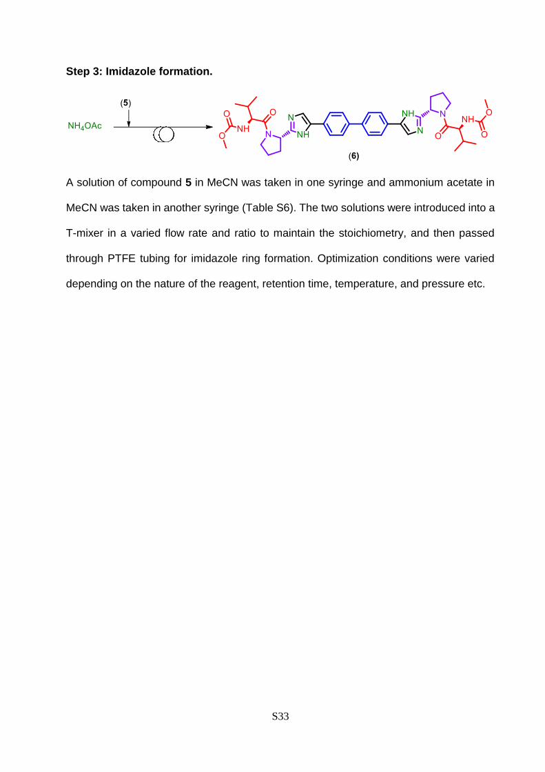
Step 3: Imidazole formation.
A solution of compound 5 in MeCN was taken in one syringe and ammonium acetate in
MeCN was taken in another syringe (Table S6). The two solutions were introduced into a
T-mixer in a varied flow rate and ratio to maintain the stoichiometry, and then passed
through PTFE tubing for imidazole ring formation. Optimization conditions were varied
depending on the nature of the reagent, retention time, temperature, and pressure etc.

S34
Table S6. Optimization of continuous micro-flow reaction to synthesize daclatasvir API (6) in ultra-fast manner.
Entry Flow rate (mL/min) Temperature
(oC)
Pressure
(bar)
Retention
time (min.)
Yield (%)
Compound 5 NH4OAc 11
1 4.7 0.25 160 17 3.20 23
2 4.5 0.50 160 17 3.20 66
3 4.2 0.75 160 17 3.20 84
4 4.0 1.0 160 17 3.20 83
5 3.7 1.25 160 17 3.20 79
6 4.9 0.90 160 17 2.67 82
7 5.4 0.97 160 17 2.46 69
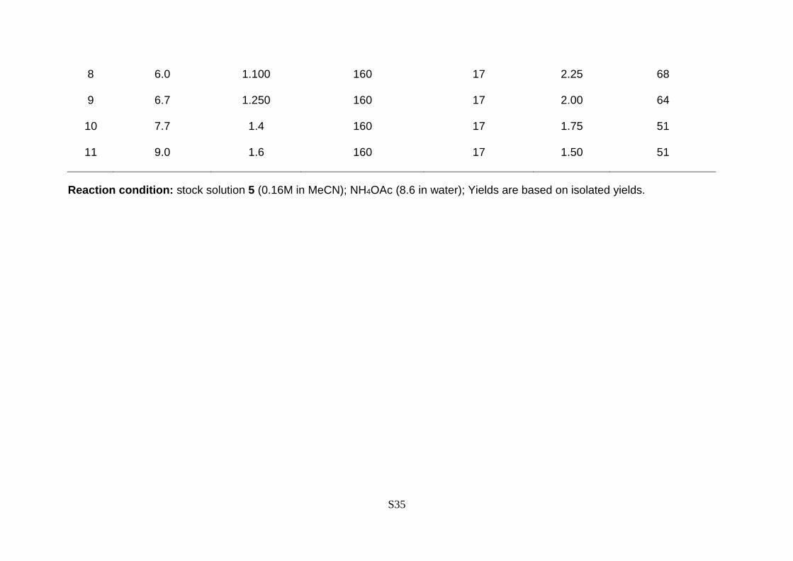
S35
8 6.0 1.100 160 17 2.25 68
9 6.7 1.250 160 17 2.00 64
10 7.7 1.4 160 17 1.75 51
11 9.0 1.6 160 17 1.50 51
Reaction condition: stock solution 5 (0.16M in MeCN); NH4OAc (8.6 in water); Yields are based on isolated yields.

S36
Fig. S12. Schematic presentation of continuous micro-flow synthesis of daclatasvir API
(6).
The reactant 5 dissolved in MeCN (0.16 M) was charged in one syringe. In another
syringe was taken solution of NH4OAc (8.6 M in MeCN) (Fig. S12). The two solutions
were introduced to a T-mixer in a flow rate with the ratio of 1: 9.6 (compound 5: NH4OAc)
to maintain the stoichiometry, and then passed through a PTFE tubing (id = 1000 µm, l =
20.4 meter, vol. = 16 ml) to occur the ester formation during 3.2 min of residence time
and 160 oC temperature and 17 bar pressure (Table S6, entry 3). The product was
collected in reservoir containing cold water and extracted through the routine process.
1H NMR (300 MHz, DMSO) δ 8.17 (s, 1H), 8.04 (d, J = 8.2 Hz, 2H), 7.94 (d, J = 8.4 Hz,
2H), 7.29 (d, J = 8.4 Hz, 1H), 5.22 (t, J = 6.8 Hz, 1H), 4.20 – 3.98 (m, 2H), 3.84 (s, 1H),
3.54 (s, 3H), 2.35 (dd, J = 20.1, 12.9 Hz, 1H), 2.28 – 1.96 (m, 4H), 0.99 – 0.81 (m, 3H),
0.77 (d, J = 6.6 Hz, 3H). 13C NMR (75 MHz, DMSO) δ 170.95, 156.93, 149.31, 139.14,
131.66, 127.15, 126.47, 125.86, 115.00, 31.03, 28.93, 24.89, 19.56, 17.71. IR (max):
3283, 2964, 1707, 1628, 1524, 1441, 1361, 1246, 1189, 1106, 1035, 831,755 cm-1. MS
(EI): m/z 738.39 (M+).S15
S37
5. Spectra
Fig. S13. 1H NMR spectra of biphenyl (2a) in CDCl3.
S38
Fig. S14. 13C NMR spectra of biphenyl (2a) in CDCl3.

S39
Fig. S15. 1H NMR spectra of 4,4’-dimethyl-1,1’-biphenyl (2b) in CDCl3.
S40
Fig.S16. 13C NMR spectra of 4,4’-dimethyl-1,1’-biphenyl (2b) in CDCl3.

S41
Fig. S17. 1H NMR spectra of 3, 3’-dimethyl-1,1’-biphenyl (2c) in CDCl3.

S42
Fig. S18. 13C NMR spectra of 3, 3’-dimethyl-1,1’-biphenyl (2c) in CDCl3.

S43
Fig. S19. 1H NMR spectra of 1,1’ -binaphthalene (2d) in CDCl3.
S44
Fig. S20. 13C NMR spectra of 1,1’ -binaphthalene (2d) in CDCl3.

S45
Fig. S21. 1H NMR spectra of 2,2’ -binaphthalene (2e) in CDCl3.

S46
Fig. S22. 13C NMR spectra of 2,2’ -binaphthalene (2e) in CDCl3.

S47
Fig. S23. 1H NMR spectra of 1, 1’:4’, 1’’:4’’, 1’’’-quaterphenyl (2f) in CDCl3.
S48
Fig. S24. 13C NMR spectra of 1, 1’:4’, 1’’:4’’, 1’’’-quaterphenyl (2f) in CDCl3.

S49
Fig. S25. 1H NMR spectra of 1,1'-([1,1'-biphenyl]-4,4'-diyl) diethanone (2g) in CDCl3.

S50
Fig. S26. 13C NMR spectra of 1,1'-([1,1'-biphenyl]-4,4'-diyl) diethanone (2g) in CDCl3.

S51
Fig. S27. 1H NMR spectra of 1,1'-([1,1'-biphenyl]-4,4'-diyl) diethanone (2h) in CDCl3.

S52
Fig. S28. 13C NMR spectra of 1,1'-([1,1'-biphenyl]-4,4'-diyl) diethanone (2h) in CDCl3.
S53
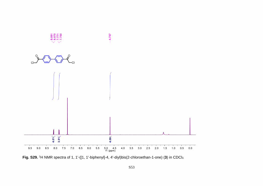
Fig. S29. 1H NMR spectra of 1, 1'-([1, 1'-biphenyl]-4, 4'-diyl)bis(2-chloroethan-1-one) (3) in CDCl3.

S54
Fig. S30. 13C NMR spectra of 1, 1'-([1,1'-biphenyl]-4, 4'-diyl)bis(2-chloroethan-1-one) (3) in CDCl3.

S55
Fig. S31. IR spectra of 1, 1'-([1, 1'-biphenyl]-4, 4'-diyl)bis(2-chloroethan-1-one) (3).
S56
Fig. S32. 1H NMR spectra of 1-((S)-2-((methoxycarbonyl)amino)-3-methylbutanoyl)pyrrolidine-2-carboxylic acid (4).
S57
Fig. S33. 13C NMR spectra of 1-((S)-2-((methoxycarbonyl)amino)-3-methylbutanoyl)pyrrolidine-2-carboxylic acid (4).

S58
Fig. S34. 1H NMR spectra of 2-(4'-(2-(((methoxycarbonyl)-D-valyl-D-prolyl)oxy)acetyl)-[1, 1'-biphenyl]-4-yl)-2-oxoethyl
(methoxycarbonyl)-L-valyl-L-prolinate (5) in CDCl3.

S59
Fig. S35. 13C NMR spectra of 2-(4'-(2-(((methoxycarbonyl)-D-valyl-D-prolyl)oxy)acetyl)-[1, 1'-biphenyl]-4-yl)-2-oxoethyl
(methoxycarbonyl)-L-valyl-L-prolinate (5) in CDCl3.
S60
Fig. S36. IR spectra of 2-(4'-(2-(((methoxycarbonyl)-D-valyl-D-prolyl)oxy)acetyl)-[1, 1'-biphenyl]-4-yl)-2-oxoethyl (methoxycarbonyl)-
L-valyl-L-prolinate (5).

S61
Fig. S37. 1H NMR spectra of Daclatasvir (6) in DMSO-d6.

S62
Fig. S38. 13C NMR spectra of daclatasvir (6) in DMSO-d6.

S63
Fig. S39. IR spectra of daclatasvir (6).
S64
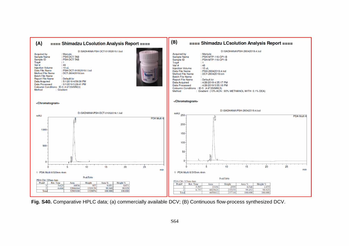
Fig. S40. Comparative HPLC data; (a) commercially available DCV; (B) Continuous flow-process synthesized DCV.

S65
Fig. S41. Pictorial set-up for the halobenzene to DCV synthesis.

S66
6. Supporting references
1. Ghosh, S. K.; Grover, A. K.; Dey, G. K.; Totlani, M. K. Surf. Coat. Tech. 2000, 126, 48.
2. Raub, M. E. B. C. J. Platinum Metals Rev. 1988, 32, 188.
3. Aand, D.; Karekar, S.; Mahajan, B.; Pawar, A. B.; Singh, A. K. Green Chem. 2018, 20,
4584.
4. Nadri, S.; Azadi, E.; Ataei, A.; Joshaghani, M.; Rafiee, E. J. Organomet. Chem. 2011,
696, 2966.
5. Li, J.-H.; Xie, Y.-X.; Yin, D.-L. The Journal of Organic Chemistry 2003, 68, 9867.
6. Pinxterhuis, E. B.; Visser, P.; Esser, I.; Gualtierotti, J.-B.; Feringa, B. L. Angew. Chem.
Int. Ed. 2018, 57, 9452.
7. Buter, J.; Heijnen, D.; Vila, C.; Hornillos, V.; Otten, E.; Giannerini, M.; Minnaard, A. J.;
Feringa, B. L. Angew. Chem. Int. Ed. 2016, 55, 3620.
8. Cheng, Y.; Gu, X.; Li, P. Organic Lett. 2013, 15, 2664.
9. Zhou, Y.; You, W.; Smith, K. B.; Brown, M. K. Angew. Chem. Int. Ed. 2014, 53, 3475.
10. Peng, Z.; Hu, G.; Qiao, H.; Xu, P.; Gao, Y.; Zhao, Y. J.Org. Chem. 2014, 79, 2733.
11. Vantourout, J. C.; Miras, H. N.; Isidro-Llobet, A.; Sproules, S.; Watson, A. J. B. J. Am.
Chem. Soc. 2017, 139, 4769.
12. Johnson, J. J. L. D. S. John Wiley & Sons, 2015, 43.
13. Medikonduri, S. S., Rammohan; Indukuri, Venkata Sunil Kumar; Kalindi, Srihari Raju;
Chava, Satyanarayana World Intellectual Prop. Org. 2017, 021904 A1.
14. Seiwert, B. B. J. B. N. V. S. S. D. WO2011075607A1 2010, WO2011/075607.
15. Hamm, S. K. P. P. G. M. J. S. J. US Patent 2008, US7728027B2.