micro air corporation - aj madison
TRANSCRIPT
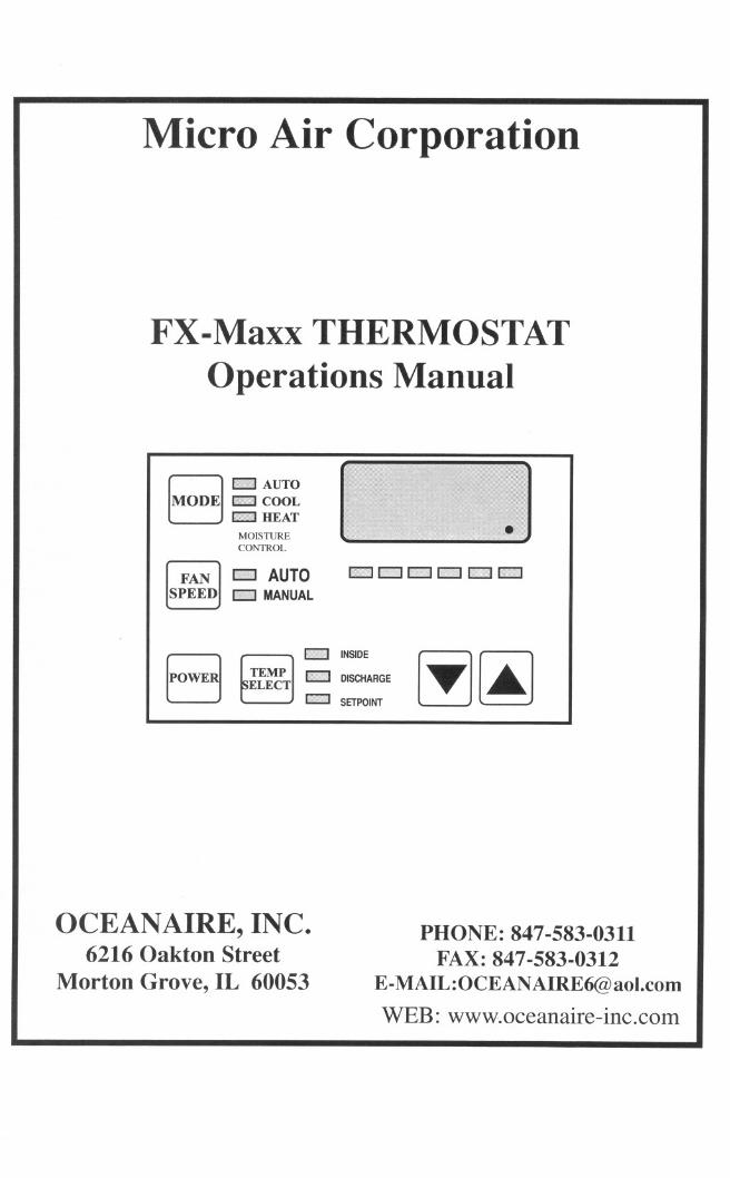
Micro Air Corporation
FX-Maxx THERMOSTATOperations Manual
B I>'n] AUTO
MODE I>'>" COOLIMMM'IHEAT
MOISTURECONTROL
I FAN] - AUTOSPEED -MANUAL
Eil II_I I' c na
[POWE1 Sit~T :: ::'RGE [Tn..]1,,1 SETPOINT
OCEANAIRE, INC.6216 Oakton Street
Morton Grove, IL 60053
PHONE: 847-583-0311FAX: 847-583-0312
E-MAIL:[email protected]: www.oceanaire-inc.com

FX-Maxx Operations Manual
CONTENTS
FX-Maxx Operations ManualMicro Air Corporation124 Route 526Allentown, NJ 08501
BASICOPERATION....... ... ...... ... 1OPERATOR CONTROLS AND DISPLAY PANEL 2 & 3
MODES OF OPERATION ... 4
MOISTURE CONTROL MODE. ... 4
FANMODES 5
SPECIFICATIONS 6
WIRING DIAGRAMS ...... .... . . ......... .. 7 & 8
Copyright @ 1997 Micro Air Corporation, All Rights Reserved
No part of this publication may be reproduced, translated, stored in a retrieval system, ortransmitted on any form or by means electronic, mechanical, photocopying, recording orotherwise without prior written consent by Micro Air Corporation.
Every precaution has been taken in the preparation of this manual to insure its accuracy.However, Micro Air Corporation assumes no responsibility for efforts and omissions. Neitheris any liability assumed for damages resulting from the use of this product and informationcontained herein.
Revision: 03 01/02/98

FX-Maxx Operations Manual BASIC OPERATION
POWER BUTTON Press the power button once to toggle the unit to the on mode. Press the powerbutton again to toggle the unit to the off mode.
[ FAN ]II1II AUTOSPEED MANUAL
I' ;,1 10J!IWi1I +;,','1 IF' %'1 191' &I IID>':I1
FAN BUTTON Press and release the fanbutton to advance from auto to manual fan.Press and release to increase the manual fanspeeds, 1 through 6. Press and release againreturns to the auto fan mode. The selected fanmode is indicated by the Auto and Manual fanLED's
B INb':lI] AUTO
MODE ""'"Mi. COOLI':':II'IIIIHEAT
MOISTURECONTROL
BINI'I;]1:" INSIDE
TEMP1
1§:@]1'1 DISCHARGEELECT
E;9JWI SETPOINT
UP BUTTON Momentarily press and the setpoint will appear in the temperature display.
rwl W I
The set point increases one degree each time
~ ~ the up button is pressed and released.
DOWN BUTTON Momentarily press and release to display the set point. The set point is decreasedone degree each time the down button is pressed and released.
MODE BUTTON The mode button is used to select one of 4 Operating Modes. Press and release toadvance to the next mode. Continue to press and release until the desired Operating Mode is reached.The mode selected is indicated by the Mode LED.
TEMP SELECT BUTTON Press and release to view inside [return] air temperature, outside[discharge] air temperature or set point. The appropriate LED will be lit indicating the temperature is dis-played.
THREE DIGIT DISPLAY The inside [return] temperature is displayed whenever the control is turnedon. The display provides a readout of the inside air temperature which is located in the supply duct.
HEA T MODE LED The heat mode LED is lit when Heating is selected.
COOL MODE LED The cool mode LED is lit when the Cooling is selected.
AUTO LED The auto LED is lit when the "Automatic Heating or Cooling Mode is selected. The controlwill automatically switch to heating or cooling when this mode is selected.
MOISTURE CONTROL LED The moisture LED is lit when the Moisture Control is selected.
MANUAL FAN LED The manual fan LED is lit when a manual fan speeds is selected.
AUTO FAN LED The auto fan LED is lit when automatic fan speed operation is selected.
FAN SPEED BAR GRAPH There are six [6] individual fan speed LED's. Each LED represents one[1] fan speed. Low fan [1] is indicated by illuminating the first LED. High fan speed is indicated by illu-minating all six [6] LED's.
COMPRESSOR LED The system operating status [Compressor On or Off] is indicated by turningOn the right most decimal point in the 3 Digit Display.
Revision: 03 01/02/98 Page 1

FX-Maxx Operations Manual OPERATOR CONTROLS AND DISPLAY PANEL
Refer to figure 1 for the buttons locations and display functions listed on the following pages.
FX-MaxxDisplay Panel
[::Jt:;i AUTO~ I;:;'" ~~~
7
MOISTURECONTROL
[ FAN ] .. AUTOSPEED tm;"? MANUAL
18
1314
12
15
1 8 TEMPELECT
IIImoo INSIDE
DISCHARGE
I, I SETPOINT ~~6
16
17 4 3
Figure 1: FX-Maxx Control Buttons and Indicator Displays
1. POWER BUTTON The power button is used to toggle between the on and off modes.Press the power button once to toggle the unit to the on mode. Press the power button again totoggle the unit to the off mode.
2. FAN BUTTON Press and release the fan button to advance from auto fan to manualfan. Press and release the fan button to advance the manual fan speeds, 1 through 6. Press andrelease again to return to the automatic fan mode. The selected fan mode is indicated by theauto and manual fan LED's.
3. UP BUTTON Momentarily press the up button and the set point will appear in thetemperature display. Press and release the up button to increase the set point one degree. Theset point is increased by one degree each time the up button is pressed and released. The high-est set point allowed is 85° F. The up button is used in conjunction with the down button to dis-play the outside air temperature when the control is on.
4. DOWN BUTTON Momentarily press and release the down button to display the setpoint. Press and release the down button to decrease the set point. The set point is decreasedone degree each time the down button is pressed and released. The lowest set point allowed is55° Fahrenheit. The down button is used in conjunction with the up button to display the out-side air temperature when the control is on.
Revision: 03 01/02/98 Page 2
109
5
8 -II'
2

FX-Maxx Operations Manual
5. MODE BUTTON The mode button is used to select one of the four operating modes. Press andrelease the mode button and the FX-Maxx will advance to the next mode. Continue to press and release theMode button until the desired operating mode is reached. The mode selected is indicated by the Mode LED, i.e., "Cool, Heat, Automatic or Moisture Mode.
6. TEMP SELECT BUTTON Press and release the Temp Select Button to view inside air tempera-ture, discharge air temperature or the set point. The appropriate LED, Inside, Discharge or Set Point will be litindicating which temperature is being displayed. If no outside air sensor is installed three [3] dashes will appearin the Three Digit Display.
7. THREE DIGIT SEVEN SEGMENT DISPLAY The inside air temperature is displayed in thewindow whenever the control is turned on. The three digit 7 segment display provides a readout of the inside airtemperature which is located in the face plate.
The display also indicates fault codes and discharge air temperature when the discharge air sensor is installed.
The display momentarily indicates the set point when the up or down button is pressed.
When the control resumes operation after a power interruption all the display LEDs will turn on for one second.This is a normal operating condition and is referred to as "Power On Reset".
8. HEAT MODE LED The heat mode LED will be lit when the Heat Mode has been selected. The heatmode LED is also lit when the optional electric heat is installed and the heat mode is selected.
9. COOL MODE LED The cool mode LED will be lit when the Cooling Mode has been selected.
10. AUTO LED The autoLEDislitwhentheautomaticheatingorcoolingmodehasbeenselected. The controlwill automatically switch to heating or cooling when this mode is selected.
'\
11. MOISTURE CONTROL LED The moisture mode LED is lit when the Moisture Control has beenselected. This mode is used to control humidity during periods when the temperature is satisfied but humidity isstill high.
12. MANU AL FAN LED The manual fan LED will be lit when one of six manual fan speeds has beenselected.
13. AUTO FAN LED The auto fan LED is illuminated when automatic fan speed operation has been selected.
14. FAN SPEED BAR GRAPH There are six [6] individual fan speed LED's in the Fan Speed BarGraph. Each LED represents one [1] fan speed. Low fan speed [1] is indicated by illuminating the first LED.High fan speed is indicated by illuminating all six [6] LED's. Any of the six [6] fan speeds available are dis-played by illuminating the appropriate LED's.
15. INSIDE LED The inside LED is lit when the inside air temperature is being displayed.
16. DISCHARGE LED The discharge LED is turned on when the discharge temperature is displayed.
17. SET POINT LED The set point LED is turned on when the set point is displayed.
18. COMPRESSOR LED The system operating status [Compressor On or Offl is indicated byturning On the right most decimal point in the 3 Digit Display.
'"
Revision: 03 01/02/98 Page 3

FX-Maxx Operations Manual MODES OF OPERATION
Off ModeWhen the FX-Maxx is in the off mode, all control outputs are turned off. Operating parametersand user settings are saved in nonvolatile memory.
On Mode
When the control is in the on mode, power will be supplied to the appropriate control outputsand the display will indicate the current state of operation. The operating and program parame-ters resume based on those stored the last time the unit was operating.
Cool Only ModeWhen Cool LED is on, only the cooling systems are selected and operated as required. Whenthe temperature drops below the set point, the system will not automatically switch to the heat-ing mode. Cooling only is available for customers that do not want automatic cooling and heat-ing operation.
Heating Only ModeWhen the Heat LED is on, only the heating systems are selected and operated as required.Should the temperature rise above the set point, the system will not automatically switch to thecooling mode. Heating only is supplied for customers that require the system to not automati-cally switch from the heating to the cooling mode.
Automatic Mode
When the Automatic LED is on, both heating and cooling are supplied as required. The heatand cool LEDs will be lit according to the mode required. When the system requires compres-sor operation for heating or cooling the right most decimal point [ I 8] will turn on when thecompressor ISon.
Temperature in a given mode will be maintained at two degrees Fahrenheit 2° F, however, afour degree difference is required to allow the control to change modes. Once in a new mode,the temperature will remain within two degrees Fahrenheit 2° F of the set point.
Moisture Mode
While in the on mode, press the Mode Button until the Moisture Mode LED is illuminated.Every four (4) hours, the fan is started and air circulated for thirty (30) minutes. During thistime the air temperature is sampled and entered into memory. The cooling cycle is started andcontinues until the temperature is lowered 2° F. The compressor is allowed a maximum of onehour running time to reach the desired temperature. Four (4) hours after the temperature is sat-isfied or the compressor the cycle will be repeated. The right most decimal point is lit while the. .compressor ISrunmng.
Revision: 03 01/02/98 Page 4

FX-Maxx Operations Manual FAN MODES
Automatic Fan SpeedsFX-Maxx has 6 automatic fan speeds. Speed 6 is high, 3 is medium and 1 is low or the slowest speed,Automatic fan mode allows the FX-Maxx to determine the required fan speed based on room temperature.The closer the room temperature is to the set point, the slower the fan will run. This permits a balance be-tween the most efficient temperature control and slower, quieter fan speeds. Automatic fan operation isthe factory default, however, manual fan speed control is available.
Manual Fan ModeSix (6) is the fastest and 1 represents the slowest speed. Manual fan modeallows the user to select and maintain the desired fan speed manually.When a manual fan speed has been selected, the fan speed bar graphwill indicate the speed selected by the number of LED's lit.Select speed 3, for example, and the first 3 LEDs in the fan bar graph will turnon. Manual fan is sometimes preferred when room temperature is constantly changing due to varying heatloads.
FAN SPEEDS- - _I,W"",'].?})??II""HW/!
1 2 3 4 5 6
FAIL SAFE AND FAULT HANDLING CODES
When a fault is detected FX-Maxx will display one of the following Mnemonic fault codes:
HPF indicates high Freon pressure. 15 Second Delay Ignored in Heat Mode.
LAC indicates low AC line power
AAA ... .indicates failed air sensor. Unit will not run until repaired.
Fail-SafeThere are four levels of fail-safe protection including the fail-safe off mode. Level one monitorsthe sensors, takes appropriate action and allows continuous restarts after a 90 second delay...Does not display the fault code. Level two worjis the same as level one, however, the appropri-ate fault code mnemonic is displayed during the time-out between restarts. Level three is identi-cal to level two with the inclusion of a three successive failures lockout routine. After four [4]consecutive failures the system is shut down and a manual reset is required.
Lockout
Lockout occurs if four consecutive faults are detected within a heating or cooling cycle. Lockoutcauses the system to shut down and flash the appropriate mnemonic fault code. Lockout can onlybe cleared by turning the unit off, then .on with the power button.
F auit DisplayWhen a fault occurs the appropriate mnemonic code is flashed in the display. The flashing mne-monic can be removed from the display by pressing and releasing the power button to reset thecontrol. Resetting the control does not solve the problem that caused the fault!
Revision: 03 01/02/98 Page 5

FX-Maxx Operations Manual SPECIFICATIONS
SPECIFICATIONS
SET POINT RANGE 55°F to 85°F
TEMPERATURE RANGE DISPLAYED OaF to 150°F
TEMPERATURE SENSOR RANGE... . " ... ... ... .. . .. . ... OaF to 150°F
FREQUENCY """ ... '" ... 50 OR 60 Hz
FAN OUTPUT... ... """ """ """ 6 Amps @ 230 VAC
VALVE OR REA TER OUTPUT 6 Amps @ 230 VAC
PUMP OUTPUT 125 volt 1/4 HP @ 125 VAC
PUMP OUTPUT 250 volt 1/2 HP @ 250 VAC
COMPRESSOR OUTPUT 125 volt 1 HP @ 125 VAC
COMPRESSOR OUTPUT 250 volt 2 HP @ 250 VAC
DISPLAY DIMENSIONS
DISPLAY PANEL 5.310" X 4.130"
DISPLAY PANEL CUT OUT 5.5" X 4.5"
PC BOARD DIMENSIONS
LENGTH ... ... """""" """ ..., 7.000"
WIDTH... """ ,. ... ... '" 3.750"
HEIGHT 1.560"
Revision: 03 01/02/98 Page 6

1..J::.. DISPLAY OAT/H20 I I~ n Sdr ~I\I 11\1
C:::::>I 0 ..J::..
ODD I c::> :R:: ~
OB n~ qOonD ~ ICLo ~00 q g 01 qI g = ~ ==>-
g QClo1o~IO\'-'{Jq~DD
DI ID
On Jpl i
FX-Moxx f!l.erations Manual
Place this sensor indischarge air stream
~ 0
Compressor
FX-MAxx WIRING DIAGRAM
Tank Full Cutout SwitchC olNO
r-- Place this sensor
/ in returnairstream
AC-1 t
L1 L2
ReversingVOlve 11OVor 230Vor trOlsformer con be comectedbetween valve output Old valve.
Revision: 03 01/02/98 Page7

FX-Maxx f!J!.erationsManual
FX1-WilingDiagram
High Pressure Switch
D-~.So-\-t DISPLAY OATIH2O 9dr. 1:11...J.Wnn ~-C::::::>I In c:::JQOO~ -t
OB 'io QDjJ 0 g I 7'=00 q ~ 01 QI"IHP ~ odB:
~ 0 d~n~nnONW ~ 0 D -c::::J-
I
n a D V~~g°0 CJ! 1°
0 On nOc=> B~ 0
L1 L2
Compressor
Reversing valve 11OVor 230Vor transformer can be connectedbetween \/ClIve output anv valve.
Revision: 03 01/02198Page 8