micom p124 · technical guide p124/en t/e44 micom p124 page 1/2 self & dual powered overcurrent...
TRANSCRIPT

MiCOM P124
Self & Dual Powered Overcurrent Relays
P124/EN T/E44
Technical Guide


Technical Guide P124/EN T/E44 MiCOM P124 Page 1/2
SELF & DUAL POWERED OVERCURRENT RELAYS
MiCOM P124
CONTENT
Safety instructions
Introduction Chapter 1
Handling, installation and case dimensions Chapter 2
User Guide P124 Self-powered Relay Chapter 3-1
Menu Content MiCOM P124 Self-powered Chapter 3-2
User Guide P124 Dual-powered Relay Chapter 4-1
Menu Content MiCOM P124 Dual-powered Chapter 4-2
Technical data & curves characteristics Chapter 5
Applications Guide Chapter 6
Commissioning and Maintenance Guide Chapter 7
Communication Database Chapter 8
Connection Diagrams APPENDIX 1
Commissioning test and record sheets APPENDIX 2

P124/EN T/E44 Technical Guide Page 2/2 MiCOM P124

Pxxx/EN SS/G11
SAFETY SECTION


Pxxx/EN SS/G11 Safety Section Page 1/8
STANDARD SAFETY STATEMENTS AND EXTERNAL LABEL INFORMATION FOR SCHNEIDER ELECTRIC EQUIPMENT
1. INTRODUCTION 3
2. HEALTH AND SAFETY 3
3. SYMBOLS AND EXTERNAL LABELS ON THE EQUIPMENT 4
3.1 Symbols 4 3.2 Labels 4
4. INSTALLING, COMMISSIONING AND SERVICING 4
5. DECOMMISSIONING AND DISPOSAL 7
6. TECHNICAL SPECIFICATIONS FOR SAFETY 8
6.1 Protective fuse rating 8 6.2 Protective Class 8 6.3 Installation Category 8 6.4 Environment 8

Pxxx/EN SS/G11 Page 2/8 Safety Section
BLANK PAGE

Pxxx/EN SS/G11 Safety Section Page 3/8
1. INTRODUCTION
This guide and the relevant equipment documentation provide full information on safe handling, commissioning and testing of this equipment. This Safety Guide also includes descriptions of equipment label markings.
Documentation for equipment ordered from Schneider Electric is despatched separately from manufactured goods and may not be received at the same time. Therefore this guide is provided to ensure that printed information which may be present on the equipment is fully understood by the recipient.
The technical data in this safety guide is typical only, see the technical data section of the relevant product publication(s) for data specific to a particular equipment.
Before carrying out any work on the equipment the user should be familiar with the contents of this Safety Guide and the ratings on the equipment’s rating label.
Reference should be made to the external connection diagram before the equipment is installed, commissioned or serviced.
Language specific, self-adhesive User Interface labels are provided in a bag for some equipment.
2. HEALTH AND SAFETY
The information in the Safety Section of the equipment documentation is intended to ensure that equipment is properly installed and handled in order to maintain it in a safe condition.
It is assumed that everyone who will be associated with the equipment will be familiar with the contents of that Safety Section, or this Safety Guide.
When electrical equipment is in operation, dangerous voltages will be present in certain parts of the equipment. Failure to observe warning notices, incorrect use, or improper use may endanger personnel and equipment and also cause personal injury or physical damage.
Before working in the terminal strip area, the equipment must be isolated.
Proper and safe operation of the equipment depends on appropriate shipping and handling, proper storage, installation and commissioning, and on careful operation, maintenance and servicing. For this reason only qualified personnel may work on or operate the equipment.
Qualified personnel are individuals who:
• Are familiar with the installation, commissioning, and operation of the equipment and of the system to which it is being connected;
• Are able to safely perform switching operations in accordance with accepted safety engineering practices and are authorised to energize and de-energize equipment and to isolate, ground, and label it;
• Are trained in the care and use of safety apparatus in accordance with safety engineering practices;
• Are trained in emergency procedures (first aid).
The equipment documentation gives instructions for its installation, commissioning, and operation. However, the manual cannot cover all conceivable circumstances or include detailed information on all topics. In the event of questions or specific problems, do not take any action without proper authorization. Contact the appropriate Schneider Electric technical sales office and request the necessary information.

Pxxx/EN SS/G11 Page 4/8 Safety Section
3. SYMBOLS AND EXTERNAL LABELS ON THE EQUIPMENT
For safety reasons the following symbols and external labels, which may be used on the equipment or referred to in the equipment documentation, should be understood before the equipment is installed or commissioned.
3.1 Symbols
Caution: refer to equipment documentation
Caution: risk of electric shock
Protective Conductor (*Earth) terminal
Functional/Protective Conductor (*Earth) terminal. Note: This symbol may also be used for a Protective Conductor (Earth) Terminal if that terminal is part of a terminal block or sub-assembly e.g. power supply.
*NOTE: THE TERM EARTH USED THROUGHOUT THIS GUIDE IS THE DIRECT EQUIVALENT OF THE NORTH AMERICAN TERM GROUND.
3.2 Labels
See Safety Guide (SFTY/4L M/G11) for equipment labelling information.
4. INSTALLING, COMMISSIONING AND SERVICING
Equipment connections
Personnel undertaking installation, commissioning or servicing work for this equipment should be aware of the correct working procedures to ensure safety.
The equipment documentation should be consulted before installing, commissioning, or servicing the equipment.
Terminals exposed during installation, commissioning and maintenance may present a hazardous voltage unless the equipment is electrically isolated.
The clamping screws of all terminal block connectors, for field wiring, using M4 screws shall be tightened to a nominal torque of 1.3 Nm.
Equipment intended for rack or panel mounting is for use on a flat surface of a Type 1 enclosure, as defined by Underwriters Laboratories (UL).
Any disassembly of the equipment may expose parts at hazardous voltage, also electronic parts may be damaged if suitable electrostatic voltage discharge (ESD) precautions are not taken.
If there is unlocked access to the rear of the equipment, care should be taken by all personnel to avoid electric shock or energy hazards.
Voltage and current connections shall be made using insulated crimp terminations to ensure that terminal block insulation requirements are maintained for safety.
Watchdog (self-monitoring) contacts are provided in numerical relays to indicate the health of the device. Schneider Electric strongly recommends that these contacts are hardwired into the substation's automation system, for alarm purposes.

Pxxx/EN SS/G11 Safety Section Page 5/8
To ensure that wires are correctly terminated the correct crimp terminal and tool for the wire size should be used.
The equipment must be connected in accordance with the appropriate connection diagram.
Protection Class I Equipment
- Before energizing the equipment it must be earthed using the protective conductor terminal, if provided, or the appropriate termination of the supply plug in the case of plug connected equipment.
- The protective conductor (earth) connection must not be removed since the protection against electric shock provided by the equipment would be lost.
- When the protective (earth) conductor terminal (PCT) is also used to terminate cable screens, etc., it is essential that the integrity of the protective (earth) conductor is checked after the addition or removal of such functional earth connections. For M4 stud PCTs the integrity of the protective (earth) connections should be ensured by use of a locknut or similar.
The recommended minimum protective conductor (earth) wire size is 2.5 mm² (3.3 mm² for North America) unless otherwise stated in the technical data section of the equipment documentation, or otherwise required by local or country wiring regulations.
The protective conductor (earth) connection must be low-inductance and as short as possible.
All connections to the equipment must have a defined potential. Connections that are pre-wired, but not used, should preferably be grounded when binary inputs and output relays are isolated. When binary inputs and output relays are connected to common potential, the pre-wired but unused connections should be connected to the common potential of the grouped connections.
Before energizing the equipment, the following should be checked:
- Voltage rating/polarity (rating label/equipment documentation),
- CT circuit rating (rating label) and integrity of connections,
- Protective fuse rating,
- Integrity of the protective conductor (earth) connection (where applicable),
- Voltage and current rating of external wiring, applicable to the application.
Accidental touching of exposed terminals
If working in an area of restricted space, such as a cubicle, where there is a risk of electric shock due to accidental touching of terminals which do not comply with IP20 rating, then a suitable protective barrier should be provided.
Equipment use
If the equipment is used in a manner not specified by the manufacturer, the protection provided by the equipment may be impaired.
Removal of the equipment front panel/cover
Removal of the equipment front panel/cover may expose hazardous live parts, which must not be touched until the electrical power is removed.

Pxxx/EN SS/G11 Page 6/8 Safety Section
UL and CSA/CUL Listed or Recognized equipment
To maintain UL and CSA/CUL Listing/Recognized status for North America the equipment should be installed using UL or CSA Listed or Recognized parts for the following items: connection cables, protective fuses/fuseholders or circuit breakers, insulation crimp terminals and replacement internal battery, as specified in the equipment documentation.
For external protective fuses a UL or CSA Listed fuse shall be used. The Listed type shall be a Class J time delay fuse, with a maximum current rating of 15 A and a minimum d.c. rating of 250 Vd.c., for example type AJT15.
Where UL or CSA Listing of the equipment is not required, a high rupture capacity (HRC) fuse type with a maximum current rating of 16 Amps and a minimum d.c. rating of 250 Vd.c. may be used, for example Red Spot type NIT or TIA.
Equipment operating conditions
The equipment should be operated within the specified electrical and environmental limits.
Current transformer circuits
Do not open the secondary circuit of a live CT since the high voltage produced may be lethal to personnel and could damage insulation. Generally, for safety, the secondary of the line CT must be shorted before opening any connections to it.
For most equipment with ring-terminal connections, the threaded terminal block for current transformer termination has automatic CT shorting on removal of the module. Therefore external shorting of the CTs may not be required, the equipment documentation should be checked to see if this applies.
For equipment with pin-terminal connections, the threaded terminal block for current transformer termination does NOT have automatic CT shorting on removal of the module.
External resistors, including voltage dependent resistors (VDRs)
Where external resistors, including voltage dependent resistors (VDRs), are fitted to the equipment, these may present a risk of electric shock or burns, if touched.
Battery replacement
Where internal batteries are fitted they should be replaced with the recommended type and be installed with the correct polarity to avoid possible damage to the equipment, buildings and persons.
Insulation and dielectric strength testing
Insulation testing may leave capacitors charged up to a hazardous voltage. At the end of each part of the test, the voltage should be gradually reduced to zero, to discharge capacitors, before the test leads are disconnected.
Insertion of modules and pcb cards
Modules and PCB cards must not be inserted into or withdrawn from the equipment whilst it is energized, since this may result in damage.
Insertion and withdrawal of extender cards
Extender cards are available for some equipment. If an extender card is used, this should not be inserted or withdrawn from the equipment whilst it is energized. This is to avoid possible shock or damage hazards. Hazardous live voltages may be accessible on the extender card.

Pxxx/EN SS/G11 Safety Section Page 7/8
External test blocks and test plugs
Great care should be taken when using external test blocks and test plugs such as the MMLG, MMLB and MiCOM P990 types, hazardous voltages may be accessible when using these. *CT shorting links must be in place before the insertion or removal of MMLB test plugs, to avoid potentially lethal voltages.
*Note: When a MiCOM P992 Test Plug is inserted into the MiCOM P991 Test Block, the secondaries of the line CTs are automatically shorted, making them safe.
Fiber optic communication
Where fiber optic communication devices are fitted, these should not be viewed directly. Optical power meters should be used to determine the operation or signal level of the device.
Cleaning
The equipment may be cleaned using a lint free cloth dampened with clean water, when no connections are energized. Contact fingers of test plugs are normally protected by petroleum jelly, which should not be removed.
5. DECOMMISSIONING AND DISPOSAL
De-commissioning The supply input (auxiliary) for the equipment may include capacitors across the supply or to earth. To avoid electric shock or energy hazards, after completely isolating the supplies to the equipment (both poles of any dc supply), the capacitors should be safely discharged via the external terminals prior to de-commissioning.
Disposal
It is recommended that incineration and disposal to water courses is avoided. The equipment should be disposed of in a safe manner. Any equipment containing batteries should have them removed before disposal, taking precautions to avoid short circuits. Particular regulations within the country of operation, may apply to the disposal of the equipment.

Pxxx/EN SS/G11 Page 8/8 Safety Section
6. TECHNICAL SPECIFICATIONS FOR SAFETY
Unless otherwise stated in the equipment technical manual, the following data is applicable.
6.1 Protective fuse rating
The recommended maximum rating of the external protective fuse for equipments is 16A, high rupture capacity (HRC) Red Spot type NIT, or TIA, or equivalent. Unless otherwise stated in equipment technical manual, the following data is applicable. The protective fuse should be located as close to the unit as possible.
CAUTION - CTs must NOT be fused since open circuiting them may produce lethal hazardous voltages.
6.2 Protective Class
IEC 60255-27: 2005
EN 60255-27: 2006
Class I (unless otherwise specified in the equipment documentation). This equipment requires a protective conductor (earth) connection to ensure user safety.
6.3 Installation Category
IEC 60255-27: 2005
EN 60255-27: 2006
Installation Category III (Overvoltage Category III):
Distribution level, fixed installation.
Equipment in this category is qualification tested at 5 kV peak, 1.2/50 µs, 500 Ω, 0.5 J, between all supply circuits and earth and also between independent circuits.
6.4 Environment
The equipment is intended for indoor installation and use only. If it is required for use in an outdoor environment then it must be mounted in a specific cabinet or housing which will enable it to meet the requirements of IEC 60529 with the classification of degree of protection IP54 (dust and splashing water protected).
Pollution Degree - Pollution Degree 2 Compliance is demonstrated by reference Altitude - Operation up to 2000m to safety standards.
IEC 60255-27:2005
EN 60255-27: 2006

Technical Guide P124/EN T01/B44 MiCOM P124
CHAPTER 1 Introduction


Technical Guide P124/EN T01/B44 Introduction CHAPTER 1 MiCOM P124 Page 1/6
CONTENT
1. INTRODUCTION 3
2. HOW TO USE THIS MANUAL 3
3. INTRODUCTION TO THE MiCOM P124 RELAYS 4
4. MAIN FUNCTIONS 5

P124/EN T01/B44 Technical Guide CHAPTER 1 Introduction Page 2/6 MiCOM P124
PAGE BLANCHE

Technical Guide P124/EN T01/B44 Introduction CHAPTER 1 MiCOM P124 Page 3/6
1. INTRODUCTION
The overcurrent relays of the MiCOM P124 series are Schneider Electric™s self- and dual-powered relays. The MiCOM P124 series are designed to control, protect and supervise industrial plants as well as public distribution systems and substations and do not require an external power supply. They may also be used as backup to distance protection relays in electrical transmission networks.
2. HOW TO USE THIS MANUAL
This guide provides a description of the overcurrent relays:
− MiCOM P124 self-powered relay,
− MiCOM P124 dual-powered relay.
It allows the user to become familiar with the relays' applications, installation, setting and commissioning.
This manual has the following format :
Chapter 1. Introduction
Contents of the manual and general introduction to the MiCOM P124 of relays covered by the Guide.
Chapter 2. Handling, installation and case dimensions
Precautions to be taken when handling electronic equipment.
Chapter 3. User Guide of MiCOM P124 self-powered relays
A detailed description of the features of the MiCOM P124 self-powered relay.
Chapter 4. User Guide of MiCOM P124 dual-powered relays
A detailed description of the features of the MiCOM P124 dual-powered relay.
Chapter 5. Technical specifications and curves characteristics
Comprehensive details on nominal values, setting ranges, specifications and curves characteristics
Chapter 6. Application Guide
Detailed recommendations for choosing the CTs.
Chapter 7. Commissioning and Maintenance Guide
Guide to commissioning, problem solving and maintenance of MiCOM P124 relays.
APPENDICES :
• Connection diagrams
• Commissioning test records
• Hardware and Software versions historical

P124/EN T01/B44 Technical Guide CHAPTER 1 Introduction Page 4/6 MiCOM P124
3. INTRODUCTION TO THE MiCOM P124 RELAYS
The range of MiCOM protection relays follows on from the success of the MIDOS, K, MODN and OPN ranges by incorporating the last changes in digital technology. The relays from the MiCOM P124 are fully compatible and use the same modular box concept. The MiCOM P124 of relays provides more protection for the most demanding applications.
Each relay has a large number of functions for controlling and collecting data. This can form part of a fully integrated system covering protection, control, instrumentation, data acquisition and the recording of faults, events and disturbances. The relays are equipped on the front panel with a liquid crystal display (LCD) with 2 x 16 back-lit alphanumerical characters, a tactile 7 button keypad (to gain access to all the parameters, alarms and measurements) and 8 LEDs simply displaying the state of the MiCOM P124 relays. In addition, the use of the RS485 communication port makes it possible to read, reinitialise and change the settings of the relays, if required, from a local or remote PC computer equipped with appropriate software.
An RS232 port is available on the front panel of the MiCOM P124 relays for downloading a software version (for updating, changing language, etc) and connecting the PC equipped with the support software MiCOM S1.
Its flexibility of use, reduced maintenance requirements and ease of integration allow the MiCOM P124 to provide an evolving solution for the problems of the protection of electric networks.
The MiCOM P124 relays provide earth fault and overcurrent protection for electrical distribution systems, industrial systems and any application requiring overcurrent protection where no auxiliary supply is available or where the auxiliary supply is not reliable. The earth fault element is sensitive enough for use with electrical systems where the earth fault current is low.

Technical Guide P124/EN T01/B44 Introduction CHAPTER 1 MiCOM P124 Page 5/6
4. MAIN FUNCTIONS
The following table shows the functions available in the various models of the MiCOM P124 of relays.
Type SELF-POWERED (Order code Vaux = S)
DUAL-POWERED (Order code Vaux = A, F, or M)
Protection functions
Non-directional three-phase overcurrent (50/51)
X X
Non-directional earth fault overcurrent (50N/51N)
X X
Instantaneous thresholds X X
Thermal overload (49) X X
Negative sequence overcurrent (46) X
Undercurrent (37) X (note 1)
Circuit breaker failure (50 BF) X
Cold load pickup X (note 1)
Broken conductor detection X
Blocking logic X (note 1)
Relay selective scheme logic X (note 1)
Output relays latching (86) X (note 1)
Fail-safe operation X
Autorecloser option (79) X (note 1)
Ancillary functions
Dual power supply (Vaux + CT) X
Output for striker X X
Trip changeover output relay for CB coil
X X
Healthy LED 1 led (note 2) 1 led (note 2)
Other LEDs No 3 + 4 programmable
Magnetic flag for trip information 1 1
4 magnetic flags option No option 4 programmable
Setting groups 1 2
Measurements (true RMS values) X X
Current maximum and average values X X
Fault records X (note 4) X
Event records X (note 1)
Disturbance records X (note 1)
Circuit breaker supervision X
Communication RS485 rear port Not applicable X
Communication RS232 front port X (note 3) X (note 3)

P124/EN T01/B44 Technical Guide CHAPTER 1 Introduction Page 6/6 MiCOM P124
NOTES : (1) Functions not available in case of loss of auxiliary power supply
(2) The Healthy LED indicates that the relay is being powered by either the auxiliary voltage or the CTs above the minimum required current.
(3) For the self-powered MiCOM P124 relay, and for the dual- powered MiCOM P124 relay during loss of auxiliary voltage, the power necessary to set the relay can be provided via this RS232 port, thanks to the battery box MiCOM E1.
(4) Simplified fault record (date and time not available).

Technical Guide P124/EN T02/C44 MiCOM P124
CHAPTER 2 Handling, Installation and Case
Dimensions


Technical Guide P124/EN T02/C44 Handling, installation and CHAPTER 2 case dimensions Page 1/8 MiCOM P124
CONTENT
1. GENERAL CONSIDERATIONS 3
1.1 Receipt of relays 3
1.2 Electrostatic discharge (ESD) 3
2. HANDLING OF ELECTRONIC EQUIPMENT 4
3. RELAY MOUNTING 5
4. UNPACKING 5
5. STORAGE 5
6. CASE DIMENSIONS 6

P124/EN T02/C44 Technical Guide CHAPTER 2 Handling, installation and case dimensions Page 2/8 MiCOM P124
BLANK PAGE

Technical Guide P124/EN T02/C44 Handling, installation and CHAPTER 2 case dimensions Page 3/8 MiCOM P124
1. GENERAL CONSIDERATIONS
1.1 Receipt of relays
Protective relays, although generally of robust construction, require careful treatment prior to installation on site. Upon receipt, relays should be examined immediately to ensure no damage has been sustained in transit. If damage has been sustained during transit a claim should be made to the transport contractor and Schneider Electric should be promptly notified.
Relays that are supplied unmounted and not intended for immediate installation should be returned to their protective polythene bags.
1.2 Electrostatic discharge (ESD)
The relays use components that are sensitive to electrostatic discharges.
The electronic circuits are well protected by the metal case and the internal module should not be withdrawn unnecessarily. When handling the module outside its case, care should be taken to avoid contact with components and electrical connections. If removed from the case for storage, the module should be placed in an electrically conducting antistatic bag.
There are no setting adjustments within the module and it is advised that it is not unnecessarily disassembled. Although the printed circuit boards are plugged together, the connectors are a manufacturing aid and not intended for frequent dismantling; in fact considerable effort may be required to separate them. Touching the printed circuit board should be avoided, since complementary metal oxide semiconductors (CMOS) are used, which can be damaged by static electricity discharged from the body.

P124/EN T02/C44 Technical Guide CHAPTER 2 Handling, installation and case dimensions Page 4/8 MiCOM P124
2. HANDLING OF ELECTRONIC EQUIPMENT
A person's normal movements can easily generate electrostatic potentials of several thousand volts. Discharge of these voltages into semiconductor devices when handling electronic circuits can cause serious damage, which often may not be immediately apparent but the reliability of the circuit will have been reduced.
The electronic circuits are completely safe from electrostatic discharge when housed in the case. Do not expose them to risk of damage by withdrawing modules unnecessarily.
Each module incorporates the highest practicable protection for its semiconductor devices. However, if it becomes necessary to withdraw a module, the following precautions should be taken to preserve the high reliability and long life for which the equipment has been designed and manufactured.
1. Before removing a module, ensure that you are at the same electrostatic potential as the equipment by touching the case.
2. Handle the module by its frontplate, frame or edges of the printed circuit board. Avoid touching the electronic components, printed circuit track or connectors.
3. Do not pass the module to another person without first ensuring you are both at the same electrostatic potential. Shaking hands achieves equipotential.
4. Place the module on an antistatic surface, or on a conducting surface which is at the same potential as yourself.
5. Store or transport the module in a conductive bag.
If you are making measurements on the internal electronic circuitry of an equipment in service, it is preferable that you are earthed to the case with a conductive wrist strap. Wrist straps should have a resistance to ground between 500kΩ − 10ΜΩ.
If a wrist strap is not available you should maintain regular contact with the case to prevent a build-up of static. Instrumentation which may be used for making measurements should be earthed to the case whenever possible.
More information on safe working procedures for all electronic equipment can be found in BS5783 and IEC 147-OF. It is strongly recommended that detailed investigations on electronic circuitry or modification work should be carried out in a special handling area such as described in the above-mentioned BS and IEC documents.

Technical Guide P124/EN T02/C44 Handling, installation and CHAPTER 2 case dimensions Page 5/8 MiCOM P124
3. RELAY MOUNTING
Relays are dispatched either individually or as part of a panel/rack assembly.
If an MMLG test block is to be included it should be positioned at the right-hand side of the assembly (viewed from the front). Modules should remain protected by their metal case during assembly into a panel or rack.
For individually mounted relays an outline diagram is supplied in section 6 of this chapter showing the panel cut-outs and hole centres.
4. UNPACKING
Care must be taken when unpacking and installing the relays so that none of the parts is damaged or the settings altered. Relays must only be handled by skilled persons. The installation should be clean, dry and reasonably free from dust and excessive vibration. The site should be well lit to facilitate inspection. Relays that have been removed from their cases should not be left in situations where they are exposed to dust or damp. This particularly applies to installations which are being carried out at the same time as construction work.
5. STORAGE
If relays are not to be installed immediately upon receipt they should be stored in a place free from dust and moisture in their original cartons. Where de-humidifier bags have been included in the packing they should be retained. The action of the de- humidifier crystals will be impaired if the bag has been exposed to ambient conditions and may be restored by gently heating the bag for about an hour, prior to replacing it in the carton.
Dust which collects on a carton may, on subsequent unpacking, find its way into the relay; in damp conditions the carton and packing may become impregnated with moisture and the de-humifier will lose its efficiency.
Storage temperature : 25°C to +70°C.

P124/EN T02/C44 Technical Guide CHAPTER 2 Handling, installation and case dimensions Page 6/8 MiCOM P124
6. CASE DIMENSIONS
MiCOM P124 relays are available in a 4U metal case for panel or flush mounting.
Weight : about 2.9 Kg
External size : Height Case 152 mm Front panel 177 mm Width Case 148,1 mm Front panel 155 mm Depth Case 140,8 mm Front panel + case 166 mm
150(Top)
Front panel
148.1
4 holes Ø 3.4
4 holes Ø 4.4
168
(Holes sizes)
158 ±0.5
Flush mounting
139.825.1155
(Front)
177
(Right)
10
Flush mounting
155.2
129.6
103.6
10.2
23.2
Trip
Alarm
Warning
Healthy
MiCOM P124
+ 0.80
Trip
IA = 214A

Technical Guide P124/EN T02/C44 Handling, installation and CHAPTER 2 case dimensions Page 7/8 MiCOM P124
MiCOM E1 Battery case sizes :
Height Case 30 mm Width Case 68 mm Length Case 110 mm

P124/EN T02/C44 Technical Guide CHAPTER 2 Handling, installation and case dimensions Page 8/8 MiCOM P124
BLANK PAGE

Technical Guide P124/EN T31/B44 MiCOM P124
CHAPTER 3-1 User Guide
P124 Self-powered Relay


Technical Guide P124/EN T31/B44 User Guide CHAPTER 3-1 MiCOM P124 Page 1/24
CONTENT
1. DESCRIPTION OF THE MiCOM P124 RELAYS 3
1.1 General information 3
1.2 Trip of the circuit breaker 3
2. USER INTERFACE 5
2.1 Front panel display and keypad 5
2.1.1 The display 5
2.1.2 Keypad 5
2.2 Front panel LED and magnetic flag 6
2.3 The two areas under the top and bottom flaps 6
2.4 The battery box 6
2.5 Description of the MiCOM P124 self-powered front panel 7
2.5.1 LEDs 7
2.5.2 Magnetic flag 7
3. MENUS 8
3.1 Default display 8
3.2 Access to the menu 8
3.3 Password 8
3.3.1 Password protection 8
3.3.2 Entering the password 8
3.3.3 Changing the password 9
3.4 ALARM display 9
3.4.1 Electrical system ALARMS 9
3.4.2 Relay Hardware or Software ALARMS 10
3.5 Menu contents 11
3.5.1 O.P. Parameters menu 12
3.5.2 CONFIGURATION Menu 13
3.5.3 MEASUREMENTS Menu 14
3.5.4 PROTECTION Menu 15
3.5.4.1 [50/51] Phase OC sub-menu 15
3.5.4.2 [50N/51N] E/Gnd sub-menu 17
3.5.4.3 [49] Therm OL sub-menu 19

P124/EN T31/B44 Technical Guide CHAPTER 3-1 User Guide Page 2/24 MiCOM P124
3.5.5 AUTOMAT. CTRL Menu 20
3.5.5.1 Trip Commands sub-menu 20
3.5.6 RECORD Menu 21
3.5.6.1 Fault Record sub-menu 21
3.5.6.2 Time Peak Value 22
4. WIRING 23
4.1 Current inputs (measurement) 23
4.2 Output relays 23
4.3 Striker output 24
4.4 RS 232 Front Communication port 24
Technical Guide P124/EN T31/B44 User Guide CHAPTER 3-1 MiCOM P124 Page 3/24
1. DESCRIPTION OF THE MiCOM P124 RELAYS
1.1 General information
The MiCOM P124 relays, in their self-powered and dual-powered versions, make best use of numerical techniques to provide protection and control functions.
They have 4 analogue inputs (3 phase currents and 1 earth current). The current inputs have to be specified on order (1A or 5A).
The front panel allows the user access to the information in the relay, either via the LEDs and/or magnetic flags, or via the LCD and keypad.
The various alarms are saved in memory and are available to the user on the backlit LCD. Reading and clearing of these alarms are possible without password.
Wiewing the settings and measurements is not password protected but modification or deletion can only be done after entering the saved password.
MiCOM P124 dual-powered version:
The MiCOM relay dual-powered version can be powered either by an external power supply source or by the line currents from the CTs (the minimum load current must be over 0.2 In on at least one phase).
MiCOM P124 self-powered version:
This model provides fully comprehensive protection functions without and external power supply.
The power is taken from line currents provided by the CTs (the minimum load current must be over 0.2 In on at least one phase).
THIS CHAPTER 3 OF THE P124 TECHNICAL GUIDE DESCRIBES THE USER INTERFACE AND THE CONNECTIONS OF THE SELF-POWERED VERSION OF THE MiCOM P124 RELAY.
1.2 Trip of the circuit breaker
Whatever the version (dual or self-powered), the MiCOM P124 relays can trip the circuit breaker via a C/O contact or striker output.
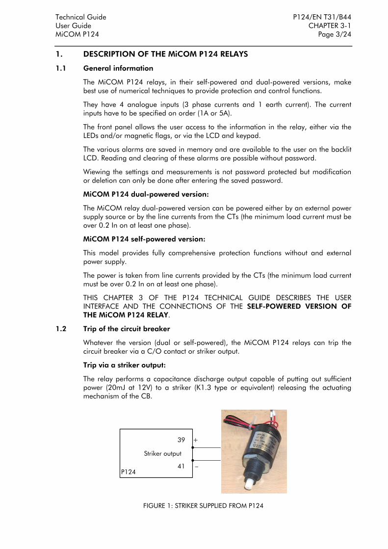
Trip via a striker output:
The relay performs a capacitance discharge output capable of putting out sufficient power (20mJ at 12V) to a striker (K1.3 type or equivalent) releasing the actuating mechanism of the CB.
P124
Striker output
39 +
41
FIGURE 1: STRIKER SUPPLIED FROM P124

P124/EN T31/B44 Technical Guide CHAPTER 3-1 User Guide Page 4/24 MiCOM P124
This tripping output is completely independent from any auxiliary supply.
Trip via a changeover contact:
The relay performs a changeover contact relay output with a high breaking capacity to trip the circuit breaker coil.
The operation of the changeover contact is completely independent from any auxiliary supply. On the other hand, an auxiliary supply will be necessary for the supply of the CB coil.
Auxiliary supply
P124
RL1
44
42
40
Auxiliary supply
FIGURE 2: TRIP OF THE CB COIL VIA A CHANGEOVER CONTACT

Technical Guide P124/EN T31/B44 User Guide CHAPTER 3-1 MiCOM P124 Page 5/24
2. USER INTERFACE
The MiCOM P124 relay front panel serves as an interface between the user and the protection relay. It enables the user to enter relay settings, display the measured values, alarms and display clearly the various actions carried out by MiCOM P124 relay.
The front panel of the relay consists of three separate sections:
− The LCD display and the keypad,
− The LED's
− The two zones under the upper and lower flaps.
The battery box (accessory):
Associated with the MiCOM P124 relays, the battery box MiCOM E1 can be used to allow the user to access the menu when there is no line current (circuit breaker open).
2.1 Front panel display and keypad
2.1.1 The display
The front panel of the MiCOM P124 relays caries a liquid crystal display (LCD) on which data such as settings, measured values and alarms can be viewed. The data is accessed through a menu system.
The liquid crystal display has two lines each with sixteen characters. A back-light is activated when any key is pressed and will remain lit for five minutes after the last key press. This allows the display to be read in most lighting conditions.
NOTA : IN ORDER TO SAVE ENERGY, THE LCD IS BACKLIT ONLY WHEN THERE IS AT LEAST ONE PHASE CURRENT ABOVE 0.5 In.
2.1.2 Keypad
The keypad has seven keys divided into two groups :
Two keys situated immediately under the screen (keys ! and ").
Five main keys situated at the middle of the front face are for programming.
The two keys ! and " are dedicated for reading and acknowledging the alarms. So as to display successive alarms, press on key ". The alarms are presented in reverse order for their detection (the most recent first, the oldest last). So as to acknowledge the alarms, the user can either acknowledge each alarm using ! or go to the end of the ALARM menu and carry out a general acknowledgement.
NOTA : NO PASSWORD IS REQUIRED TO ACKNOWLEDGE ALARMS.
The five keys situated in the middle of the MiCOM front panel are dedicated to setting the relay.
The # $ % & keys make it possible to move in the direction indicated to the various levels of the menus. The ' key validates a choice or value (modification of settings).

P124/EN T31/B44 Technical Guide CHAPTER 3-1 User Guide Page 6/24 MiCOM P124
2.2 Front panel LED and magnetic flag
One LED and one magnetic flag are available for the self-powered version of the P124 relay.
The default corresponding labels on the front panel are in the English language but the user is provided with a set of French stickers.
2.3 The two areas under the top and bottom flaps
Under the upper flap, a label identifies the relay according to its model (ordering code) and series number. This information defines the product uniquely and specifically.
In making all requests for information from Schneider Electric After Sales Department, please quote these two numbers.
Information indicated in the lower portion of this label covers the nominal earth current value and the rated current (1A or 5A).
Under the lower flap, an RS232 port is available to download a new version of the protection software, as well as the settings created in a dedicated PC software MiCOM S1. The same software allows to view all the relays internal data (measurements, events…).
When there is no line current from the CTs (circuit breaker open), the user can view or modify the settings by powering the MiCOM P124 relay with the battery box MiCOM E1 connected to the RS232 port.
The withdrawal of the MiCOM active part (chassis) from the case is effected by opening the two flaps, then with a 3mm screwdriver, turn the extractor situated under the upper flap, and pull using the two slots situated behind these flaps.
2.4 The battery box
To MiCOM P124RS 232
Battery box
Input forexternal supply12Vcc – 24Vcc
FIGURE 3: BATTERY BOX MiCOM E1
The battery box performs the two following functions:
1. Temporary powering of the relay in order to allow the user to view or modify data. The battery used is a 6LR61 type (9V) which can power the relay up to 3 hours. When the battery is flat it is possible to power the battery box with an external dc supply. The dc voltage value must be comprised between 12Vdc and 24Vdc.
2. RS232 interface between the MiCOM P124 relay and the PC equipped with the setting software MiCOM S1.

Technical Guide P124/EN T31/B44 User Guide CHAPTER 3-1 MiCOM P124 Page 7/24
2.5 Description of the MiCOM P124 self-powered front panel
2 tactile buttonsto view andacknowledgealarms andindications
Healthy LED
5-key keypad forsettings andviewing
RS 232
Retractable flapsallowing toremove theactive part of therelay
2 x 16 characterbacklit display
Magnetic flag fortrip indication
Battery boxMiCOM E1
FIGURE 4: MiCOM P124 SELF-POWERED FRONT PANEL
2.5.1 LEDs
One LED is available on the left hand side of the front panel:
LED 4 Colour: GREEN Label: HEALTHY
This LED is lit when the relay correctly powered by a sufficient line current, provided by one or several CTs.
The LED is also lit when the relay is powered by the battery box.
Note: the front panel of the self-powered relay has holes meant for the dual-powered relay. On the self-powered relay, only LED 4 is used.
2.5.2 Magnetic flag
The magnetic flag indicates that a tripping command has been issued to the CB coil or striker by switching to yellow.
The flag can be reset (black side) by depressing the ! key either the relay is being powered by the battery box when the circuit breaker is open, or when it is powered by a sufficient line current.

P124/EN T31/B44 Technical Guide CHAPTER 3-1 User Guide Page 8/24 MiCOM P124
3. MENUS
The menu of the MiCOM P124 relays is organised into main and sub menus.
3.1 Default display
By default, the value of the current IA is continuously displayed.
As soon as an alarm is generated by the MiCOM relay, that information is considered as priority and replaces the default value.
3.2 Access to the menu
Complete menu access is performed by manipulation of the keys # $ % &.
The general arrangement of the menus is shown in figure 3.
Reading of parameters and measurements is possible without entering the password.
Modification of the parameters requires entering the password.
Should an error be made in entering a parameter, press ! to cancel.
Except for reading and cancelling, the keys ! and " are inactive.
NOTA : The letter P is displayed at the botton-right of each first (main menu) and second menu level when the password is entered.
This password remains active for 5 minutes of keypad inactivity.
3.3 Password
3.3.1 Password protection
Password protection is applicable to the relay settings, especially to the selection of the various thresholds, time delays, communication parameters, allocation of inputs and outputs relays.
The password consists of four alphabetical capital characters. When leaving the factory, the password is AAAA. The user can define his own combination of characters. Should the password be lost or forgotten, the modification of the stored parameters of the relay is prohibited. It is then necessary to contact the manufacturer or his agent by specifying the serial number of the relay so as to receive a stand-by password specific to the relay concerned.
3.3.2 Entering the password
The input of the password is requested as soon as a modification of a parameter is made for any one of the menus or sub-menus. The user enters for each of the 4 characters/letters and validates the entire password with '.
After 5 seconds, the display returns to the point of the preceding menu. If no action is taken on the keypad for 5 minutes, the password is deactivated. A new request shall be associated with any subsequent parameter modification.
NOTE : WHILE THE PASSWORD IS ACTIVE, IT IS NOT POSSIBLE TO DOWNLOAD A SETTING FILE FROM THE PC SETTING SOFTWARE MiCOM S1.

Technical Guide P124/EN T31/B44 User Guide CHAPTER 3-1 MiCOM P124 Page 9/24
3.3.3 Changing the password
To change the active password, go to the OP. PARAMETERS menu and then to the point of the Password sub menu. Enter the old password and validate. Then press ' and enter the new password character per character and validate the new password using '.
The message NEW PASSWORD OK is displayed to indicate that the password has changed.
3.4 ALARM display
The management of alarms is directly displayed on the LCD. The display of alarm messages has priority over the default current value. As soon as an alarm is detected by the relay (threshold crossing for example), the message is displayed on the MiCOM LCD display.
The alarm messages are classed as follows :
• Electrical power network alarm message
• Hardware or software fault message from the relay.
3.4.1 Electrical system ALARMS
Any crossing of a threshold (instantaneous or time delay) generates an "electrical network alarm". For each threshold the involved threshold is indicated. If several alarms are triggered, they are all stored in their order of appearance the most recent alarm first, the oldest alarm last. Each message is numbered and the total of messages is shown.
The user read all the alarm messages using " without entering the password.
The user acknowledges the alarms using !. The user can acknowledge each message one by one or all by going to the end of the list and acknowledge all the messages using !.
The different Electrical system alarms are described below :
I0> 1ST stage earth fault pick-up
I0>> 2nd stage earth fault pick-up
I0>>> 3rd stage earth fault pick-up
I> 1st stage overcurrent pick-up
I>> 2nd stage overcurrent pick-up
I>>> 3rd stage overcurrent pick-up
tI0> 1st stage earth fault time-out
tI0>> 2nd stage earth fault time-out
tI0>>> 3rd stage earth fault time-out
tI> 1st stage overcurrent time-out
tI>> 2nd stage overcurrent time-out
tI>>> 3rd stage overcurrent time-out
THERMAL ALARM thermal alarm threshold pick-up
THERMAL TRIP thermal trip threshold pick-up

P124/EN T31/B44 Technical Guide CHAPTER 3-1 User Guide Page 10/24 MiCOM P124
3.4.2 Relay Hardware or Software ALARMS
Any software or hardware Fault of the MiCOM relay generates a "hard/software alarm". If several alarms are acquired they are all stored in their order of appearance. Display of the alarms is in reverse order (the most recent first and the oldest last). Each message is numbered and the total of messages is indicated below.
The user can read all the alarm messages with the aid of ", without entering the password.
The acknowledgement of the relay alarm messages is IMPOSSIBLE. Only the disappearance of the cause reset the alarm.
Possible Hardware or Software alarm messages :
« EEPROM ERROR DATA » : Data in EEPROM memory in fault
« CT ERROR » : Analogue channel in fault
« EEPROM ERROR CALIBR » : Calibration zone in fault
WARNING: IN ORDER TO SAVE ENERGY, THE WATCHDOG RELAY RL0 IS USED ONLY WHEN THERE IS A 0.4 IN CURRENT ON AT LEAST ONE PHASE. RL0 IS DE-ENERGISED BELOW THAT CURRENT LEVEL OR IN CASE OF HARDWARE OR SOFTWARE PROBLEM.

Technical Guide P124/EN T31/B44 User Guide CHAPTER 3-1 MiCOM P124 Page 11/24
3.5 Menu contents
DEFAULT DISPLAY
IA = 1245 AOP PARAMETERS
CONFIGURATION
MEASUREMENTS
PROTECTION
AUTOMAT.CTRL
RECORDS
FIGURE 3 : ORGANISATION OF MICOM P124 SELF-POWERED MAIN MENU
The menu of the MiCOM P124 Self-powered (without auxiliary power supply) relays is divided into 6 sections :
OP PARAMETERS
CONFIGURATION
MEASUREMENTS
PROTECTION
AUTOMAT. CTRL
RECORDS
To access these menus from the default display use $.
To return to the default display from these menus or sub-menus press #.
NOTE: A menu content table is given in the chapter 3-2.

P124/EN T31/B44 Technical Guide CHAPTER 3-1 User Guide Page 12/24 MiCOM P124
3.5.1 O.P. Parameters menu
OP Parameters Heading of the OP PARAMETERS menu To gain access to the menu content, press $.
Password = * * * *
Entry of the password to be able to modify the MiCOM relaysettings and parameters. To enter the password, press '.
Password = AAAA
Entry of the password is made letter by letter using # $ to go up or down the alphabet. After each letter, press % to enter the following letter. At the end, press ' to validate the password. If the password is correct, the message « PASSWORD OK » is displayed on the screen. The password is initailly set in the factory to AAAA
WARNING : AS SOON AS THE PASSWORD HAS BEEN ENTERED, NO SETTING CHANGE USING THE FRONT PORT COMMUNICATION CAN BE ACCEPTED AND THIS DURING 5 MINUTES.
Description = P124 S
Displays the MiCOM P124applicable relay model S = Without auxiliary power supply (self-powered) D = Dual-powered (with auxiliary power supply)
Reference = ALST
Displays the name of the equipment associated with the relay. NOTE : The reference is initially set in the factory to ALST.
Software Version 1.B
Displays the version of the software
Frequency = 50 Hz
Nominal value of the network frequency. Select either 50 or 60 Hz. To modify this value, press ' and press # $ to select the desired value. Validate your choice using '.
Relay Status = 1 0
Displays the state of the trip logic output. (RL1) - state 0 : output relay inactive - state 1 : output relay active NOTA : The Watch-dog output (RL0) is not display in the output status menu.

Technical Guide P124/EN T31/B44 User Guide CHAPTER 3-1 MiCOM P124 Page 13/24
3.5.2 CONFIGURATION Menu
The CONFIGURATION menu is used to set the earth and phase CT ratios so that primary values can be displayed.
CONFIGURATION Heading of the CONFIGURATION menu. To gain access to the CT RATIO menu, press $, %.
CT Ratio
Heading of the CT RATIO sub-menu. To gain access to the sub-menu content, press $.
Line CT primary = 1000
Display of the primary ratio of the phase CT. The value consists of 4 digits: Minimum 1, Maximum 9999. Press ' to modify this value and use # $ % & to display the new primary phase CT ratio. Enable your choice using ' at the end of selection
E/Gnd CT primary = 1000
Display of the primary ratio of the earth CT. The consist of 4 digits : Minimum 1, Maximum 9999. Press ' to modify this value and use # $ % & to display the new primary earth CT ratio. Enable your choice using 'at the end of selection.

P124/EN T31/B44 Technical Guide CHAPTER 3-1 User Guide Page 14/24 MiCOM P124
3.5.3 MEASUREMENTS Menu
MEASUREMENTS
Heading of the MEASUREMENTS menu. To gain access to the MEASUREMENTS menu, press $, %, 2 times.
Frequency = 50.01 Hz
Display the network frequency calculated from phase currents
I A = 257.05 A
Display the A phase current (True RMS value) taking into account the phase CT ratio (CONFIGURATION/CT RATIO sub-menu).
I B = 258.80 A
Display the B phase current (True RMS value) taking into account the phase CT ratio (CONFIGURATION/CT RATIO sub-menu)
I C = 257.50 A
Display the C phase current (True RMS value) taking into account the phase CT ratio (CONFIGURATION/CT RATIO sub-menu).
I N = 20.00 A
Display the earth current (True RMS value) taking into account the earth CT ratio (CONFIGURATION/CT RATIO sub-menu).
Thermal 2 = RST = [C] 0%
Display the % thermal state based on true RMS values. To clear the % values, press !.
Max. & Average. I RST = [C]
Allows the user to clear the maximum (peak) and average (rolling) memorised values of the current. To clear these values, press !.
Max. IA Rms = 350 A
Display the peak value for phase A. The value is the true RMS maximum value.
Max. IB Rms = 0.00 A
Display the peak value for phase B. The value is the true RMS maximum value.
Max. IC Rms = 0.00 A
Display the peak value for phase C. The value is the true RMS maximum value.
Average. IA Rms = 150 A
Display the rolling value for phase A. The value is the true RMS average value.
Average. IB Rms = 148 A
Display the rolling value for phase B. The value is the true RMS average value.

Technical Guide P124/EN T31/B44 User Guide CHAPTER 3-1 MiCOM P124 Page 15/24
Average. IC Rms = 153 A
Display the rolling value for phase C. The value is the true RMS average value.
3.5.4 PROTECTION Menu
The PROTECTION menu enables a user to program various protection functions and settings (thresholds, time delay) associated with each of the phase or earth protection functions.
The various sub-menus are :
⇒ [50/51] Phase OC
⇒ [50N/51N] E/Gnd
⇒ [49] Therm OL
3.5.4.1 [50/51] Phase OC sub-menu
PROTECTION
Heading of the PROTECTION menu.
[50/51] Phase OC Heading of the [50/51] Phase OC sub-menu To gain access to the sub-menu points, press $.
I> ? Yes
Selection of the first phase threshold (I>). Select Yes or No. If the user enters I>(Yes), the following menu is displayed. If the user enters I> (No), go to I>> menu.
I> = 0.1 In
Displays the threshold current value I>. To modify this value, press '.The threshold I> is adjustable from 0.1 to 4 In. Press ' to enable your adjustment.
Delay Type DMT
Selection of the I> time delay type threshold. Select (DMT for definite time, IDMT for inverse time curves, RI for the electromechanical inverse time curve).
3.5.4.1.1 I> DMT threshold menu
Delay Type DMT
Display of the I> DMT time delay.
tl > 100 ms
Selection of the I> time delay. Select the time delay from 0 to 180 s using # and enable your choice using '.

P124/EN T31/B44 Technical Guide CHAPTER 3-1 User Guide Page 16/24 MiCOM P124
3.5.4.1.2 I> IDMT threshold, IEC or IEEE/ANSI curve menu
Delay Type IDMT
Display the I> inverse time delay (IEC or IEEE/ANSI curves).
Idmt = IEC SI
Selection of the I> curve. Select from IEC SI, IEC STI, IEC VI, IEC EI, IEC LTI, CO2, IEEE MI, CO8, IEEE VI, IEEE EI using # and enable your choice using the key '
Tms = 0.025
Select the curve TMS value. Select from 0.025 to 1.5 using # and enable your choice using '
3.5.4.1.3 I> IDMT threshold, Electromechanical RI curve menu
Delay Type RI
Display of the I> inverse time delay (electromechanical RI curve)
K = 0.1
Selection of the RI curve K value. Select from 0.100 to 10 using # and enable your choice using '.
3.5.4.1.4 I>> threshold menu
I >> ? Yes
Selection of the I>> second phase threshold. Select Yes or No. If the user enters I>>(Yes), the following menu is displayed. If the user enters I>> (No) go to I>>> menu.
I >> 2.0 In
Selection of the I>> second threshold current value. To modify this value, press '. The threshold I>>> is adjustable from 0.5 to 40 In. Press ' to enable your adjustment.
tI >> 300 ms
Selection of the second threshold I>> time delay. Select the time delay from 0 to 180 s using # and enable your choice using '.
3.5.4.1.5 I>>> threshold menu
I >>> ? Yes
Selection of the I>>> third phase threshold. Select Yes or No. If the user enters I>>>(Yes), the following menu is displayed. If the user enters I>>> (No), the LCD display returns to the heading of the menu [50/51] Phase OC.
I >>> 10.0 In
Selection of the I>>> third threshold current value. To modify this value, press '. The threshold I>>> is adjustable from 0.5 to 40 In. Press ' to enable your adjustment.
tI >>> 110 ms
Selection of the third threshold I>>> time delay. Select the time delay from 0 to 180 s using # and enable your choice using '.

Technical Guide P124/EN T31/B44 User Guide CHAPTER 3-1 MiCOM P124 Page 17/24
3.5.4.2 [50N/51N] E/Gnd sub-menu
PROTECTION
Heading of the PROTECTION menu.
[50N/51N] E Gnd Heading of the [50N/51N] E/Gnd sub-menu To gain access to the sub-menu content, press $.
le> ? Yes
Selection of the first earth threshold (Ie>). Select Yes or No. If the user enters Ie>(Yes), the following menu is displayed. User enters > (No), go to Ie>> menu.
le> 0.01 len
Displays the current threshold value Ie>. To modify this value, press '. The threshold Ie> is adjustable from :
0.002 to 1 Ien (0.002 to 1 Ien Range) 0.01 to 1 Ien (0.01 to 8 Ien Range) 0.1 to 25 Ien (0.1 to 40 Ien Range) Press ' to enable your adjustment.
Delay Type DMT
Selection of the Ie> threshold time delay type. Select (DMT for definite time, IDMT for inverse time curves, RI for the electromechanical inverse time curve) using # and enable your choice using '.
3.5.4.2.1 Ie> DMT threshold menu
Delay Type DMT
Display of the Ie> DMT time delay.
t le> 100 ms
Selection of the Ie> time delay. Select the time delay from 0 to 180 s using # and enable your choice using '.
3.5.4.2.2 Ie> IDMT threshold, IEC or IEEE/ANSI curves menu
Delay Type DMT
Display of the Ie> inverse time delay (IEC or IEEE/ANSI curves).
Idmt IEC SI
Selection of the Ie> curve. Select from IEC SI, IEC STI, IEC VI, IEC EI, IEC LTI, CO2, IEEE MI, CO8, IEEE VI, IEEE EI using # and enable your choice using the key '.
Tms 0.025
Selection of the selected curve Tms value. Select from 0.025 to 1.5 using # and enable your choice using '.

P124/EN T31/B44 Technical Guide CHAPTER 3-1 User Guide Page 18/24 MiCOM P124
3.5.4.2.3 Ie> IDMT threshold, Electromechanical RI curve menu
Delay Type RI
Display of the Ie> inverse time delay (electromechanical RI curve)
K 0.1
Selection of the RI curve K value. Select from 0.100 to 10 using # and enable your choice using '.
3.5.4.2.4 Ie>> threshold menu
le >> ? Yes
Selection of the Ie>> second earth threshold. Select Yes orNo. If the user enters Ie>>(Yes), the following menu isdisplayed. If the user enters>> (No) go to Ie>>> menu.
Ie >> 0.1 Ien
Selection of the Ie>> second threshold current value. To modify this value, press '. The threshold Ie>> is adjustable from : 0.002 to 1Ien (0.002 to 1 Ien Range) 0.01 to 8 Ien (0.01 to 8 Ien Range) 0.5 to 40 Ien (0.1 to 40 Ion Range) Press ' to validate your adjustment.
t Ie >> 300 ms
Selection of the second threshold Ie>> time delay. Select the time delay from 0 to 180 s using # and validate your choice using '.
3.5.4.2.5 Seuil I0>>> à temps constant CST
le >>> ? Yes
Selection of the Ie>>> third earth threshold. Select Yes or No. If the user validates Ie>>>(Yes), the following menu is displayed. If the user enters Ie>>> (No), the LCD display returns to the heading of the menu [50N/51N] E/Gnd.
Ie >>> 1.0 Ien
Selection of the Ie>>> third threshold current value. To modify this value, press 'T he threshold Ie>>> is adjustable from : 0.002 to 1Ien (0.002 to 1 Ien Range) 0.01 to 8 Ien (0.01 to 8 Ien Range) 0.5 to 40 Ien (0.1 to 40 Ion Range) Press ' to validate your adjustment.
t Ie >>> 300 ms
Selection of the third threshold Ie>>> time delay. Select the time delay from 0 to 180 s using # and validate your choice using '.

Technical Guide P124/EN T31/B44 User Guide CHAPTER 3-1 MiCOM P124 Page 19/24
3.5.4.3 [49] Therm OL sub-menu
PROTECTION
Heading of the PROTECTION menu.
[49] Therm OL [Heading of the [49] Therm OL (Thermal Overload) sub- menu.
Therm OL Yes
Selection of the thermal overload function. Select Yes or No. If the user enters Yes, the following menu is displayed. If the user enters No, no menu content is displayed.
Iθ> = 0.3 In
Displays the thermal current threshold value Iθ>. To modify this value, press '. The threshold Iθ> is adjustable from 0.2 to 3.2 In step of 0.01. Press ' to validate your choice.
Te = 1 mn
Displays the Te thermal time constant associated with the thermal overload formula. To modify this value, press '. The time constant Te is adjustable from 1 min to 200 min, step of 1 min. Press ' to validate your adjustment.
k = 1.05
Displays the k factor associated with the thermal overload function. To modify this value, press '. k factor is adjustable from 1 to 1.5, step of 0.01. Press ' to validate your adjustment.
θ Trip 100%
Displays the percentage applicable to the thermal overload trip threshold. To modify this value, press '. θ Trip is adjustable from 50 % to 200 % step of 1%. Press ' to validate your adjustment.
θ Alarm ? Yes
Selection of the thermal overload alarm function. Select Yes or No. If the user validates Yes, the following menu is displayed. If the user validate No, refer to the THERMAL OVERLOAD sub-menu.
θ Alarm ? Yes
Displays the percentage applicable to the thermal overload alarm threshold. To modify this value, press '. θ Trip is adjustable from 50 % to 200 % step of 1%. Press ' to validate your adjustment.

P124/EN T31/B44 Technical Guide CHAPTER 3-1 User Guide Page 20/24 MiCOM P124
3.5.5 AUTOMAT. CTRL Menu
The AUTOMAT. CTRL Menu makes it possible to programme the various automation functions included in the MiCOM P124.
⇒ Trip Commands
3.5.5.1 Trip Commands sub-menu
This sub-menu is used to set the time-delayed thresholds which activate the striker and/or the special tripping relay and send a tripping command to the circuit breaker or contactor.
AUTOMAT. CTRL
Heading of the AUTOMAT.CTRL Menu.
Trip Commands Heading of the Trip ORDER sub-menu.
Trip tI > = Yes
Allocation of the first phase time delay overcurrent threshold (tI>) to the trip output relay and/or the striker (select Yes or No). If the user validates Yes, the trip output relay (RL1) shall be activated at the end of the time delay tI>. If the user validates No, the trip output relay (RL1) shall never be activated, even at the end of the time delay tI>.
Trip tI >> Yes
Allocation of the second phase time delay overcurrent threshold (tI>>) to the trip output. Select Yes or No.
Trip tI >>> Yes
Allocation to the third phase time delay overcurrent threshold (tI>>>) to the trip output. Select Yes or No.
Trip tIe > Yes
Allocation of the first earth time delay overcurrent threshold (tIe>) to the trip output. Select Yes or No.
Trip tIe >> Yes
Allocation of the second earth time delay overcurrent threshold (tIe>>) to the trip output. Select Yes or No.
Trip tIe >>> Yes
Allocation of the third earth time delay overcurrent threshold (tIe>>>) to the trip output. Select Yes or No.
Trip Thermal θ Yes
Allocation of the thermal overload Trip information (θ Trip) to the trip output. Select Yes or No.

Technical Guide P124/EN T31/B44 User Guide CHAPTER 3-1 MiCOM P124 Page 21/24
3.5.6 RECORD Menu
The RECORD menu makes it possible to read the MiCOM P124 records.
The various sub-menus are :
⇒ Fault Record
⇒ Time Peak Value
3.5.6.1 Fault Record sub-menu
The Fault RECORD sub-menu makes possible to read the various parameters and measurement for each of the five fault store in MiCOM P124 memory.
RECORD Heading of the RECORD menu.
Fault record
Heading of the Fault Record sub-menu
Record Number 4
Selection of the Fault record number (by selecting either 1, 2, 3, 4 or 5) to be displayed. To modify this fault record number, press ' then using # enter the required number. Validate your choice using '.
Faulted Phase Phase A
Display the faulty phase for the chosen fault record. (NONE, phase A, B, C, EARTH, AB, AC, BC, or ABC).
Threshold I>>
Display the origin of the fault that as generated the trip order.
Magnitude 1200 A
Display the magnitude of the faulty current. This value is the 50/60 Hz amplitude.

P124/EN T31/B44 Technical Guide CHAPTER 3-1 User Guide Page 22/24 MiCOM P124
3.5.6.2 Time Peak Value
The DISTURBANCE sub-menu makes possible to set the various parameters and thresholds associated to this recording function.
RECORD Heading of the RECORD menu.
Time Peak Value
Heading of the Time Peak Value sub-menu.
Time Window = 5 mn
Display of the time window during which the mean and maximum current values are stored. To change this value, press the ' key. This window can be set with the following values: 5mn, 10mn, 15mn, 30mn or 60mn. Press the ' key to confirm the setting.

Technical Guide P124/EN T31/B44 User Guide CHAPTER 3-1 MiCOM P124 Page 23/24
4. WIRING
The external connection diagrams of MiCOM P124 are provided in APPENDIX 1 to this document.
4.1 Current inputs (measurement)
The MiCOM P124 relays have 4 analogue inputs (3 phase current inputs and 1 earth current input). The rated current value of these measurement inputs is either 1A or 5A (must be specified on order).
The rated current is indicated on the front panel of the relay, behind the top flap.
WARNING: THE CONNECTION OF THE EARTH CURRENT INPUT MAY DIFFER DEPENDING ON WHETHER IT IS CONNECTED TO A CORE BALANCED CT OR TO A SUMMATION OF THE 3 PHASE CTS.
Connection to 3 phase CTs and 1 core balanced CT:
Generally, when the relay is used with three phase CTs and one core balanced CT, there is not need to power the relay through the earth channel.
In this case, the core balanced CT can be connected to terminals 47 and 48.
For some phase to earth faults, when some specific cores are used, it can be possible that the fault does not generate a current high enough* to power the relay from only one phase circuit. It will then be necessary to connect the core TC to terminals 55 and 56 in order to power the relay through the earth circuit as well.
*reminder: the MiCOM P124 relay is self-powered from a 0.2 In current on at least one phase.
Connection to 3 phase CTs:
In this case the earth current is derived from the summation of the 3 phase currents.
It is not necessary to power the relay via the earth circuit. The summation of the 3 CTs must be connected to terminals 47 and 48.
Connection to 2 phase CTs and 1 core balanced CT:
In this case it is necessary to power the relay through the earth circuit. The core balanced CT must be connected to terminals 55 and 56.
4.2 Output relays
Two output relays are available on the self-powered model:
• One trip relay (RL1) with a C/O contact (1 common, 1 normally open, 1 normally closed)
• One watchdog relay (RL0) with a C/O contact (1 common, 1 normally open, 1 normally closed)
WARNING : IN ORDER TO SAVE ENERGY, THE WATCHDOG RELAY IS USED ONLY WHEN THERE IS A 0.4 IN CURRENT ON AT LEAST ONE PHASE. IT IS DE-ENERGISED BELOW THAT CURRENT LEVEL OR WHEN A SOFTWARE OR HARDWARE FAULT IS PRESENT.

P124/EN T31/B44 Technical Guide CHAPTER 3-1 User Guide Page 24/24 MiCOM P124
4.3 Striker output
The P124 relays are fitted with a striker output used to trip the circuit breaker via a striker device in the absence of an external auxiliary supply.
The 2 terminals to be connected to the striker are polarised:
− + terminal 39
− terminal 41
according to the external connection diagrams provided in Appendix 1 of the Technical Guide.
4.4 RS 232 Front Communication port
MiCOM P124 relays provide the user an RS 232 communication port. This link is dedicated to the Setting software MiCOM S1.
The cable between the P124 and the PC is a standard RS 232 shield-cable.
RS232 PC port RS 232 Cable
MiCOM P124 end 9 pin male connector
2 2
3 3
5 5
7 7
In cases where the battery box MiCOM E1 is used to power the P124 relay, it is placed between the PC and the P124 relay.

Technical Guide P124/EN T32/B44 MiCOM P124
CHAPTER 3-2 Menu Content
MiCOM P124 Self-powered


Technical Guide P124/EN T32/B44 Menu content CHAPTER 3-2 MiCOM P124 Page 1/2
MiC
OM
P1
24
S
Men
u co
nten
tFr
om V
1A
Sof
twar
e
DEF
AU
LT D
ISPL
AY
IA =
1245
A
Pass
wor
d**
**
Des
crip
tion P1
24-
S
Refe
renc
eA
LST
Soft
war
e ve
rsio
n1.B
Freq
uenc
y50 H
z
OP
PARA
MET
ERS
Rela
y St
atus
1 0
CO
NFI
GU
RATI
ON
CT
Ratio
Line
CT
prim
ary
1000
E/G
nd C
T pr
imar
y10
00
Freq
uenc
y50
.01 H
z
I A25
7.0
5 A
I B25
8.8
0 A
I C25
7.5
0 A
MEA
SURE
MEN
TS
Ther
mal
θRS
T =
[C
]0%
Max
& A
vera
ge I
RST
= [
C]
Max
IA R
ms
0.0
2 A
I N20
.00 A
Max
IB
Rm
s0.0
2 A
Max
IC
Rm
s0.0
2 A
Ave
rage
IA R
ms
0.0
0 A
Ave
rage
IB R
ms
0.0
0 A
Ave
rage
IC R
ms
0.0
0 A
PRO
TEC
TIO
N
[50/5
1]
Phas
e O
C
I >
?Yes
I >
0.1
In
Del
ay T
ype DM
T
Del
ay T
ype ID
MT
Idm
tIE
C S
I
Del
ay T
ype
RI
K =
0.1
I>>
?Ye
sI>
>2.
0 In
tl>>
300
ms
tl >
100
ms
Tms
0.02
5
[50N
/51N
] E/G
nd
Ie >
?Yes
Ie >
0.0
1 Ie
n
Del
ay T
ype D
MT
Idm
t
IEC
SI
Tms
0.025
K0.1
Ie>
> ?
Yes
Ie>
> 0
.1 Ie
nt
Ie >
>300
ms
Ie>
>>
?Yes
Ie>
>>
1.0
Ien
t Ie
>>
> 3
00
ms
t le
>10
0 m
s
Del
ay T
ype
RI
[49]
The
rm O
L
Ther
m O
L ? Ye
s
Iθ>
0.3
In
Te1 m
n
θ Tr
ip100
%
θ A
larm
?Yes
K1.0
5
θ A
larm
100
%
AU
TOM
AT.
C
TRL
Trip
C
omm
ands
Trip
tI >
Yes
Trip
tI >
> Yes
Trip
tI >
>>
Yes
Trip
tIe
>>
Yes
Trip
tIe
>>
>Ye
s
Trip
The
rmal
θYe
s
Trip
tIe
> Yes
Faul
t Re
cord
Tim
e Pe
ak
Val
ue
Tim
e W
indo
w =
5 m
n
REC
ORD
Reco
rd N
umbe
r 4
Faul
ted
Phas
ePH
ASE
A B
Thre
shol
d l>>
Mag
nitu
de 120
0 A
I>>
> ?
Yes
I>>
>10
.0 In
tl>>
>11
0 m
s
Del
ay T
ype ID
MT

P124/EN T32/B44 Technical Guide CHAPTER 3-2 Menu content Page 2/2 MiCOM P124
BLANK PAGE

Technical Guide P124/EN T41/B44 MiCOM P124
CHAPTER 4-1 User Guide
P124 Dual-Powered Relay


Technical Guide P124/EN T41/B44 User Guide CHAPTER 4-1 MiCOM P124 Page 1/68
CONTENT
1. DESCRIPTION OF THE MiCOM P124 RELAYS 5
1.1 General information 5
1.2 Trip of the circuit breaker 6
2. USER INTERFACE 7
2.1 The LCD display and the keypad 7
2.1.1 The LCD display 7
2.1.2 Keypad 7
2.2 Front panel LED and magnetic flag 8
2.3 The two areas under the top and bottom flaps 8
2.4 The battery box 9
2.5 Description of the MiCOM P124 dual-powered front panel 10
2.5.1 Leds 10
2.5.2 Magnetic flags 11
2.5.3 Battery backup 11
3. MENUS 12
3.1 Default display 12
3.2 Access to the menu 12
3.3 Password 12
3.3.1 Password protection 12
3.3.2 Entering the password 12
3.3.3 Changing the password 13
3.4 ALARM display 13
3.4.1 Electrical system ALARMS 13
3.4.2 Relay Hardware or Software ALARMS 16
3.5 Contenu du menu 17
3.5.1 OP. PARAMETERS Menu 19
3.5.2 CONFIGURATION Menu 21
3.5.2.1 DISPLAY sub-menu 21
3.5.2.2 CT RATIO sub-menu 22
3.5.2.3 RL1 Output Relay sub-menu 22
3.5.2.4 Led 5 to 8 configuration sub-menus 23
3.5.2.5 Group Select sub-menu 26
3.5.2.6 Alarms sub-menu 27

P124/EN T41/B44 Technical Guide CHAPTER 4-1 User Guide Page 2/68 MiCOM P124
3.5.2.7 Configuration Inputs sub-menu 27
3.5.2.8 Date format sub-menu 28
3.5.3 MEASUREMENTS Menu 29
3.5.4 COMMUNICATION Menu 32
3.5.4.1 MODBUS COMMUNICATION Menu 32
3.5.4.2 Courier COMMUNICATION Menu 32
3.5.4.3 IEC 60870-5-103 COMMUNICATION Menu 33
3.5.4.4 DNP3 COMMUNICATION Menu 33
3.5.5 PROTECTION Menu 34
3.5.5.1 [50/51] Phase OC sub-menu 34
3.5.5.1.1 I> DMT threshold menu 35
3.5.5.1.2 I> IDMT threshold, IEC or IEEE/ANSI curve menu 35
3.5.5.1.2.1 I> DMT reset time, IEC curves menu 35
3.5.5.1.2.2 I> DMT reset time, ANSI curves menu 35
3.5.5.1.2.2.1 I> IDMT reset time, ANSI curves menu 35
3.5.5.1.3 I> IDMT threshold, Electromechanical RI curve menu 36
3.5.5.1.3.1 I> DMT reset time, Electromechanical RI curves menu 36
3.5.5.1.4 >> threshold menu 36
3.5.5.1.5 I>>> threshold menu 36
3.5.5.2 [50N/51N] E/Gnd sub-menu 37
3.5.5.2.1 Ie> DMT threshold menu 37
3.5.5.2.2 Ie> IDMT threshold, IEC or IEEE/ANSI curves menu 37
3.5.5.2.2.1 Ie> DMT reset time, IEC curves menu 38
3.5.5.2.2.2 Ie> DMT reset time, ANSI curves menu 38
3.5.5.2.2.3 Ie> IDMT reset time, ANSI curves menu 38
3.5.5.2.3 Ie> IDMT threshold, Electromechanical RI curve menu 38
3.5.5.2.3.1 Ie> DMT reset time, RI curves menu 38
3.5.5.2.4 Ie> threshold, LABORELEC curve 38
3.5.5.2.5 Ie>> threshold menu 39
3.5.5.2.6 Ie>>> threshold menu 39
3.5.5.3 [46] NEGATIVE Phase SEQUENCE I2> sub-menu 39
3.5.5.3.1 I2> DMT threshold menu 40
3.5.5.3.2 I2> IDMT threshold, IEC or IEEE/ANSI curves menu 40
3.5.5.3.2.1 I2> DMT reset time, IEC curves menu 40

Technical Guide P124/EN T41/B44 User Guide CHAPTER 4-1 MiCOM P124 Page 3/68
3.5.5.3.2.2 I2> DMT reset time, ANSI curves menu 40
3.5.5.3.2.3 I2> IDMT reset time, ANSI curves menu 41
3.5.5.3.3 I2> IDMT threshold, Electromechanical RI curve menu 41
3.5.5.3.3.1 I2> DMT reset time, RI curves 41
3.5.5.4 [49] Therm OL sub-menu 42
3.5.5.5 [37] UNDERCURRENT I< sub-menu 43
3.5.5.6 [79] AUTORECLOSE sub-menu 43
3.5.5.6.1 [79] EXTERNAL CB FAILURE 44
3.5.5.6.2 [79] EXTERNAL BLOCKING 44
3.5.5.6.3 [79] DEAD and RECLAIM TIMES 44
3.5.6 AUTOMAT. CTRL Menu 46
3.5.6.1 Trip Commands sub-menu 46
3.5.6.2 Latch Functions Sub-Menu 48
3.5.6.3 Blocking Logic sub-menu 49
3.5.6.4 Logic Select sub-menu 51
3.5.6.5 Outputs Relays sub-menu 52
3.5.6.6 Latch of the Output relays RL2 to RL6 55
3.5.6.7 Inputs sub-menu 56
3.5.6.8 BROKEN CONDUCTOR sub-menu 57
3.5.6.9 COLD LOAD PICK-UP sub-menu 58
3.5.6.10 CIRCUIT BREAKER FAILURE sub-menu 59
3.5.6.11 CIRCUIT BREAKER SUPERVISION sub-menu 60
3.5.7 RECORDS Menu 62
3.5.7.1 CB MONITORING sub-menu 62
3.5.7.2 Fault Record sub-menu 63
3.5.7.3 DISTURBANCE RECORD sub-menu 64
3.5.7.4 Time PEAK VALUE sub-menu 65
4. WIRING 66
4.1 Current inputs (measurement) 66
4.2 Output relays 66
4.3 Striker output 67
4.4 RS232 front communication port 67
4.5 Auxiliary supply 67
4.6 Logic inputs 68
4.7 RS485 rear communication port 68

P124/EN T41/B44 Technical Guide CHAPTER 4-1 User Guide Page 4/68 MiCOM P124
BLANK PAGE

Technical Guide P124/EN T41/B44 User Guide CHAPTER 4-1 MiCOM P124 Page 5/68
1. DESCRIPTION OF THE MiCOM P124 RELAYS
1.1 General information
The MiCOM P124 relays, in their self-powered and dual-powered versions, make best use of numerical techniques to provide protection and control functions.
They have 4 analogue inputs (3 phase currents and 1 earth current). The current inputs have to be specified on order (1A or 5A).
The front panel allows the user access to the information in the relay, either via the LEDs and/or magnetic flags, or via the LCD and keypad.
The various alarms are saved in memory and are available to the user on the backlit LCD. Reading and clearing of these alarms are possible without password.
Viewing the settings and measurements is not password protected but modification or deletion can only be done after entering the saved password.
MiCOM P124 Self-powered :
This model provides fully comprehensive protection functions without and external power supply.
The power is taken from line currents provided by the CTs (the minimum load current must be over 0.2 In on at least one phase).
MiCOM P124 Dual-powered :
The MiCOM relay dual-powered version can be powered either by an external power supply source or by the line currents from the CTs (the minimum load current must be over 0.2 In on at least one phase).
The auxiliary power supply of the relay is provided by a dc or ac auxiliary source through a high capacity internal transformer which protects the relays against short interruptions (<50ms). In case of auxiliary power loss, the relay is powered by the line CTs (downgraded mode) and performs the same functions as the self-powered model.
MiCOM P124 Dual-powered relays have available via their rear connectors, a standard RS485 port. Communication protocols can be chosen at the time of order, from MODBUS RTU, Courier, IEC 60870-5-103 or DNP3. Using the communication channel, all stored information (measurements, alarms, parameters) can be read, and settings can be modified.
RS485 based communication allows MiCOM P124 Dual-powered relays to be directly linked to a digital control system (MiCOM S10 for example). All the available data is then placed at the disposal of the supervisor and can be processed either locally or remotely.
Consultation and modification of this data can be carried out on site with a normal PC and the appropriate Schneider Electric software MiCOM S1.
It is possible to assign the output relays to any of the available control or protection functions. The logic inputs can also be assigned to the control functions.
CHAPTER 4 OF THE TECHNICAL GUIDE DESCRIBES THE USER INTERFACE AND THE CONNECTIONS OF THE MiCOM P124 RELAY DUAL-POWERED VERSION.

P124/EN T41/B44 Technical Guide CHAPTER 4-1 User Guide Page 6/68 MiCOM P124
1.2 Trip of the circuit breaker
Both versions of the MiCOM P124 relays can trip the circuit breaker from a C/O output contact and/or a heavy burden output to power a striker
Whatever the version (dual or self-powered), the MiCOM P124 relays can trip the circuit breaker via a C/O contact or striker output.
Trip via a striker output:
The relay performs a capacitance discharge output capable of putting out sufficient power (20mJ at 12V) to a striker (K1.3 type or equivalent) releasing the actuating mechanism of the CB.
P124
Striker output
39 +
41
FIGURE 1: STRIKER SUPPLIED FROM P124
This tripping output is completely independent from any auxiliary supply.
Trip via a changeover contact:
The relay performs a changeover contact relay output with a high breaking capacity to trip the circuit breaker coil.
The operation of the changeover contact is completely independent from any auxiliary supply. On the other hand, an auxiliary supply will be necessary for the supply of the CB coil.
Auxiliary supply
P124
RL1
44
42
40
Auxiliary supply
FIGURE 2: TRIP OF THE CB COIL VIA A CHANGEOVER CONTACT NOTE: The change over contact can be used with fail-safe operation.
This mode can be programmed in the "Configuration/RL1 output relay/fail-safe relay".

Technical Guide P124/EN T41/B44 User Guide CHAPTER 4-1 MiCOM P124 Page 7/68
2. USER INTERFACE
The MiCOM P124 relay front panel serves as an interface between the user and the protection relay. It enables the user to enter relay settings, display the measured values, alarms and display clearly the various actions carried out by MiCOM P124 relay.
The front panel of the relay consists of three separate sections:
− The LCD display and the keypad,
− The Led's
− The two zones under the upper and lower flaps.
The battery box (accessory):
Associated with the MiCOM P124 relays, the battery box MiCOM E1 can be used to allow the user to access the menu when there is no line current (circuit breaker open).
2.1 The LCD display and the keypad
2.1.1 The LCD display
The front panel of the MiCOM P124 relays caries a liquid crystal display (LCD) on which data such as settings, measured values and alarms can be viewed. The data is accessed through a menu system.
The liquid crystal display has two lines each with sixteen characters. A back-light is activated when any key is pressed and will remain lit for five minutes after the last key press. This allows the display to be read in most lighting conditions.
NOTA : IN CASE OF AUXILIARY POWER SUPPLY FAILURE AND IN ORDER TO SAVE ENERGY, THE LCD IS BACKLIT ONLY WHEN THERE IS AT LEAST ONE PHASE CURRENT ABOVE 0.5 IN.
2.1.2 Keypad
The keypad has seven keys divided into two groups :
Two keys situated immediately under the screen (keys ! and ").
Five main keys situated at the middle of the front face are for programming.
The two keys ! and " are dedicated for reading and acknowledging the alarms. So as to display successive alarms, press on key ". The alarms are presented in reverse order for their detection (the most recent first, the oldest last). So as to acknowledge the alarms, the user can either acknowledge each alarm using ! or go to the end of the ALARM menu and carry out a general acknowledgement.
NOTA : NO PASSWORD IS REQUIRED TO ACKNOWLEDGE ALARMS.

P124/EN T41/B44 Technical Guide CHAPTER 4-1 User Guide Page 8/68 MiCOM P124
The five keys situated in the middle of the MiCOM front panel are dedicated to set the relay.
The keys make it possible to move in the direction indicated to the various levels of the menus.
The key validates a choice or value (modification of settings).
2.2 Front panel LED and magnetic flag
Height LEDS and up to 5 magnetic flags are available for the dual-powered version of the P124 relay.
The default corresponding labels on the front panel are in the English language but the user is provided with a set of French stickers.
2.3 The two areas under the top and bottom flaps
Under the upper flap, a label identifies the relay according to its model (ordering code) and series number. This information defines the product uniquely and specifically.
In making all requests for information from Schneider Electric After Sales Department, please quote these two numbers.
Information indicated in the lower portion of this label covers the auxiliary supply voltage, the nominal earth current value and the rated current (1A or 5A).
Under the lower flap, a RS232 port is available to download a new version of the protection software, as well as the settings created in a dedicated PC software MiCOM S1. The same software allows to view all the relays internal data (measurements, events…).
In case of auxiliary power supply failure and when there is no line current from the CTs (circuit breaker open), the user can view or modify the settings by powering the MiCOM P124 relay with the battery box MiCOM E1 connected to the RS232 port.
The withdrawability of the MiCOM active part (chassis) from the case is effected by opening the two flaps, then with a 3mm screwdriver, turn the extractor situated under the upper flap, and pull using the two slots situated behind these flaps.

Technical Guide P124/EN T41/B44 User Guide CHAPTER 4-1 MiCOM P124 Page 9/68
2.4 The battery box
To MiCOM P124RS 232
Battery box
Input forexternal supply12Vcc 24Vcc
FIGURE 3: BATTERY BOX MiCOM E1
The battery box performs the two following functions:
1. Temporary powering of the relay in order to allow the user to view or modify data when the auxiliary power supply has failed. The battery used is a 6LR61 type (9V) which can power the relay up to 3 hours.
When the battery is flat it is possible to power the battery box with an external dc supply. The dc voltage value must be comprised between 12Vdc and 24Vdc.
2. RS232 interface between the MiCOM P124 relay and the PC equipped with the setting software MiCOM S1.

P124/EN T41/B44 Technical Guide CHAPTER 4-1 User Guide Page 10/68 MiCOM P124
2.5 Description of the MiCOM P124 dual-powered front panel
2 tactile keys to readand clear alarms andmessages
Healthy LEDWarning LEDAlarm LEDTrip LED
Pile
5-key keypad forsettings and viewing
RS 232
Removable flapsto extract theactive part
2 x 16 characterbacklit LCD display
Magnetic flags :- 1 trip- 4 programmable
4 programmable LEDs
FIGURE 4: MiCOM P124 DUAL-POWERED FRONT PANEL
2.5.1 Leds
Eight Leds are located in the left portion of the front face (numbered from 1 to 8 starting from the top):
Led 1 Colour : RED Label : Trip
Led 1 indicates when a trip order has been issued by the relay to the cut-off element (circuit breaker, contactor). This Led recopies the trip order issued to the Trip logic output relay and/or the striker output. Its normal state is unlit. It is illuminated as soon as a triggering order is issued. It goes out when the associated alarm is acknowledged.
NOTE: this LED is out of service when the auxiliary power supply has failed, even if sufficient line currents are present in the CTs.
Led 2 Colour : ORANGE Label : Alarm
Led 2 indicates that an alarm has been registered by MiCOM P124 relay. The alarms are either threshold crossings (instantaneous), or tripping orders (time delayed). As soon as an alarm is registered, the Led flashes. When all the stored alarms are read, the Led is illuminated continuously.
When all the alarms are acknowledged, the Led goes out.
NOTE: - the alarms generated by intantaneous indications are self or hand-resettable. - the programmation self-reset (Yes or No) is possible in the "Configuration/Alarms" menu. - this Led is out of service when the auxiliary supply has failed, even if sufficient line currents are present in the CTs.

Technical Guide P124/EN T41/B44 User Guide CHAPTER 4-1 MiCOM P124 Page 11/68
Led 3 Color : ORANGE Label : Warning
Led 3 is dedicated to the internal alarms of MiCOM P124 relay. When a « minor » internal alarm (typically communication Fault) is detected, the Led flashes continuously. When the Fault is classed as « major », the Led is illuminated continuously. The extinction of this Led is only possible by the disappearance of the cause that provoked it (repair of the module, disappearance of the Fault).
NOTA : this LED is out of service when the auxiliary power supply has failed, even if sufficient line currents are present in the CTs. In that case, equipment failure is indicated by the watchdog contact (RL0).
Led 4 Colour : GREEN Label : Healthy
This LED indicates that the MiCOM P124 relay is powered by an auxiliary voltage within the rated operative range (0.8 to 1.2Uaux). In case of auxiliary supply failure, the LED indicates that the relay is correctly powered by a sufficient line current, provided by one or several CTs.
The LED is also lit when the relay is powered by the battery box.
Led 5 to 8 Colour : RED Label : Aux.1 to 4.
These Leds can be programmed by the user on the basis of information on available thresholds (instantaneous and time-delayed) and state of the logic. The user selects the information he wishes to see associates with each Led from the menu element (Logic OR). Each Led illuminates when the associated information is valid. The extinction of each Led is linked to the acknowledgement of the associated alarms.
NOTE: these LEDs are out of service when the auxiliary power supply has failed, even if sufficient line currents are present in the CTs.
2.5.2 Magnetic flags
There are five flags on the right hand side of the front panel.
On the base model, only one flag is available. It indicates that a tripping command has been issued to the CB coil or striker by switching to yellow. This flag is functional even during auxiliary power supply failure.
Optionally (selectable on order), four extra magnetic flags are functional even during power supply failure. These flags are used as backups of LEDS 5 to 8.
2.5.3 Battery backup
The front panel of each dual-powered MiCOM P124 relay is fitted with a battery to save the event, fault and disturbance records as well as thermal state in case of auxiliary power failure
The battery used is a 3.6V lithium battery.
WARNING: ONLY RECORDS MADE WHEN AUXILIARY POWER SUPPLY IS PRESENT ARE SAVED IN MEMORY.

P124/EN T41/B44 Technical Guide CHAPTER 4-1 User Guide Page 12/68 MiCOM P124
3. MENUS
The menu of the MiCOM P124 relays is organised into main and sub menus.
3.1 Default display
By default, the current value (selected phase or earth) is continuously displayed.
As soon as an alarm is generated by the MiCOM relay, that information is considered as priority and replaces the default value.
The default display choice is made in the CONFIGURATION/Display menu.
3.2 Access to the menu
Complete menu access is performed by manipulation of the keys # $ % &.
The general arrangement of the menus is shown in figure 3.
Reading of parameters and measurements is possible without entering the password.
Modification of the parameters requires entering the password.
Should an error be made in entering a parameter, press ! to cancel.
Except for reading and cancelling, the keys ! and " are inactive.
NOTA : The letter P is displayed when the password is entered.
If no key is pushed during 5 minutes, the password becomes inactive.
3.3 Password
3.3.1 Password protection
Password protection is applicable to the relay settings, especially to the selection of the various thresholds, time delays, communication parameters, allocation of inputs and outputs relays.
The password consists of four alphabetical capital characters. When leaving the factory, the password is AAAA. The user can define his own combination of characters.
Should the password be lost or forgotten, the modification of the stored parameters of the relay is prohibited. It is then necessary to contact the manufacturer or his agent by specifying the serial number of the relay so as to receive a stand-by password specific to the relay concerned.
3.3.2 Entering the password
The input of the password is requested as soon as a modification of a parameter is made for any one of the menus or sub-menus. The user enters for each of the 4 characters/letters and validates the entire password with '.
After 5 seconds, the display returns to the point of the preceding menu.
If no action is taken on the keypad for 5 minutes, the password is desactivated. A new request shall be associated with any subsequent parameter modification. WARNING : WHILE THE PASSWORD IS ACTIVE, IT IS NOT POSSIBLE TO
DOWNLOAD A SETTING FILE FROM THE PC SETTING SOFTWARE.

Technical Guide P124/EN T41/B44 User Guide CHAPTER 4-1 MiCOM P124 Page 13/68
3.3.3 Changing the password
To change the active password, go to the OP. PARAMETERS menu and then to the point of the Password sub menu. Enter the old password and validate. Then press ' and enter the new password character per character and validate the new password using '.
The message NEW PASSWORD OK is displayed to indicate that the password has changed.
3.4 ALARM display
The management of alarms is directly displayed on the LCD. The display of alarm messages has priority over the default current value. As soon as an alarm is detected by the relay (threshold crossing for example), the message is displayed on the MiCOM LCD display and the Alarm Led (2nd Led) lights up.
The alarm messages are classed as follows :
⇒ Electrical power network alarm message
⇒ Hardware or software fault message from the relay.
3.4.1 Electrical system ALARMS
Any crossing of a threshold (instantaneous or time delay) generates an "electrical network alarm". For each threshold the involved threshold is indicated.
If several alarms are triggered, they are all stored in their order of appearance the most recent alarm first, the oldest alarm last. Each message is numbered and the total of messages is shown.
The user read all the alarm messages using " without entering the password.
The user acknowledges the alarms using !. The user can acknowledge each message one by one or all by going to the end of the list and acknowledge all the messages using !.
NOTE : note that the self-reset of the alarms generated by instantaneous (crossing of threshold) is possible by configuration in the "Configuration/Alarms/Inst. Self-reset. ?" menu.
The management of the Alarm Led is directly linked to the status of the stored alarms.
If one or several messages are NOT READ and NOT ACKNOWLEDGED, the alarm Led flashes.
If all the messages have been READ but NOT ACKNOWLEDGED, the alarm Led remains lights up continuously.
If all the messages have been READ and ACKNOWLEDGED, (if the alarm cause has been cleared) the alarm Led goes out.

P124/EN T41/B44 Technical Guide CHAPTER 4-1 User Guide Page 14/68 MiCOM P124
The different electrical systems alarms are described below :
Ie> 1ST stage earth fault pick-up
Ie>> 2nd stage earth fault pick-up
Ie>>> 3rd stage earth fault pick-up
I> 1st stage overcurrent pick-up
I>> 2nd stage overcurrent pick-up
I>>> 3rd stage overcurrent pick-up
tIe> 1st stage earth fault time-out
tIe>> 2nd stage earth fault time-out
tIe>>> 3rd stage earth fault time-out
tI> 1st stage overcurrent time-out
tI>> 2nd stage overcurrent time-out
tI>>> 3rd stage overcurrent time-out
THERMAL ALARM thermal alarm threshold pick-up
THERMAL TRIP thermal trip threshold pick-up
I< undercurrent element pick-up
BRKN COND. broken conductor indication. I2/I1 element pick-up for longer than tBC. TBC is settable in the AUTOMAT. CTRL/Broken cond. menu.
t AUX 1 t AUX1 time-out
t AUX 2 t AUX2 time-out
CB FAILURE cirduit breaker failure indication (the CB does not trip on tBF time-out) tBF is settable in the AUTOMAT. CTRL/CB Fail menu.
I 2> negative sequence current threshold pick-up
tI 2> negative sequence current threshold time-out
SF6 LOW Faulty circuit breaker indication by assignable logic input (settable in AUTOMAT. CTRL/Inputs menu).
T operating CB Operating (or tripping) time of the circuit breaker longer than the value set in the AUTOMAT. CTRL/CB Supervision menu.
CB OPEN NB Number of circuit breaker operation higher that the value set in the AUTOMAT. CTRL/CB Supervision menu.
Sum An Broken current measured higher than the value set in the AUTOMAT. CTRL/CB Supervision menu.
TRIP CIRCUIT Circuit breaker trip circuit failure for longer than the supervision timer t SUP settable in the AUTOMAT. CTRL/CB Supervision menu.

Technical Guide P124/EN T41/B44 User Guide CHAPTER 4-1 MiCOM P124 Page 15/68
CB CLOSE FAILURE Circuit breaker closing time longer than the value set in the AUTOMAT. CTRL/CB Supervision menu.
RECLOSER SUCCESS Successful reclose indication. Indicates that when the fault has been cleared upon circuit breaker reclosure, and has not re-appeared before expiry of the reclaim time.
RECLOSER LOCKED Recloser blocking indication. Generated by:
- auxiliary power supply failure during dead time (definitive trip).
- external breaker failure indication (ex. SF6 low). Indication provided via a logic input assigned to the CB FAILURE function in the AUTOMAT. CTRL/Inputs menu.
- external blocking indication, external blocking can be set by the user in the PROTECTION/ [79] AUTORECLOSE/EXT BLOCK menu. This blocking information is provided via a logic input assigned to the Block [79] function in the AUTOMAT. CTRL/Inputs menu.
- definitive trip.
- remote trip command during the reclaim time.
- pick-up of I2> or thermal trip during dead time.
- breaker failure (circuit breaker failure to trip on expiry of tBF).
- breaker operating time (or tripping time) longer than the set time.
CONFLICT RECLOS. Configuration conflict of the recloser function. This indication is generated by:
- O/O Interlock not assigned to a logic input or assigned but not wired to the input.
- no output relay assigned to the CB CLOSE function (AUTOMAT. CTRL/Output Relays menu ).
- trip contact latched.
- no recloser cycle assigned to the protection functions (PROTECTION/ [79] Autoreclose menu ).
LATCH OUTPUT RELAY Information displayed when at least an output relay (RL2 to RL6) is latched.

P124/EN T41/B44 Technical Guide CHAPTER 4-1 User Guide Page 16/68 MiCOM P124
3.4.2 Relay Hardware or Software ALARMS
Any software or hardware Fault of the MiCOM relay generates a "hard/software alarm". If several alarms are acquired they are all stored in their order of appearance. Display of the alarms is in reverse order (the most recent first and the oldest last). Each message is numbered and the total of messages is indicated below.
The user can read all the alarm messages with the aid of ", without entering the password.
The acknowledgement of the relay alarm messages is IMPOSSIBLE. Only the disappearance of the cause reset the alarm.
The management of the WARNING Led is directly linked to the status of the alarms stored in the memory.
If the fault is major (the relay cannot perform protection functions), the WARNING Led is lit fixed.
If the Fault is minor (no influence on the protection and automation function e.g.communication failure), the WARNING Led is flashing.
Possible Hardware or Software alarm messages :
Major fault :
The protection and automation functions are stopped. The RL0 watchdog relay is de-energised (35-36 contact closed).
« AUX SUPPLY LOST » : Information displayed in case of loose of auxiliary power supply and RL1 configured in fail-safe operation. The MiCOM P124 relay being self-powered by CTs.
« EEPROM ERROR DATA » : Data in EEPROM memory in fault
« CT ERROR » : Analogue channel in fault
« EEPROM ERROR CALIBR » : Calibration zone in fault
Minor fault :
The MiCOM P124 is fully operational. The RL0 watchdog relay is energised (35-36 contact open, 36-37 contact closed).
« BATTERY FAIL » : Battery in fault ; battery flat or not correctly in place.
« COMM. ERROR » : Communications failure
« RAM ERROR » : Battery backed memory
« CLOCK ERROR » : Clock error
NOTE : the "Battery fail" and "RAM error" messages can be configured displayed yes or no in the "Configuration/Alarms" menu.

Technical Guide P124/EN T41/B44 User Guide CHAPTER 4-1 MiCOM P124 Page 17/68
3.5 Contenu du menu
DEFAULT DISPLAY
IA = 1245 AOP PARAMETERS
CONFIGURATION
MEASUREMENTS
COMMUNICATION
PROTECTION G1
PROTECTION G2
AUTOMAT. CTRL
RECORDS
FIGURE 3 : ORGANISATION OF MiCOM P124 DUAL-POWERED MAIN MENU

P124/EN T41/B44 Technical Guide CHAPTER 4-1 User Guide Page 18/68 MiCOM P124
The menu of the MiCOM P124 Dual-powered relays is divided into 8 sections :
⇒ OP PARAMETERS
⇒ CONFIGURATION
⇒ MEASUREMENTS
⇒ COMMUNICATION
⇒ PROTECTION G1
⇒ PROTECTION G2
⇒ AUTOMAT. CTRL
⇒ RECORDS
To access these menus from the default display use $
To return to the default display from these menus or sub-menus press #. NOTE : a Menu content table is given in the chapter 4-2.

Technical Guide P124/EN T41/B44 User Guide CHAPTER 4-1 MiCOM P124 Page 19/68
3.5.1 OP. PARAMETERS Menu
OP PARAMETERS Heading of the OP PARAMETERS menu.
Password ****
Entry of the password to be able to modify the MiCOM relay settings and parameters. To enter the password, press '
Password AAAA
Entry of the password is made letter by letter using # $ to go up or down the alphabet. After each letter, press % to enter the following letter. At the end, press ' to validate the password. If the password is correct, the message « PASSWORD OK » is displayed on the screen.
WARNING : AS SOON AS THE PASSWORD HAS BEEN ENTERED, NO SETTING CHANGE USING THE COMMUNICATION (RS485 OR RS232) CAN BE ACCEPTED AND THIS DURING 5 MINUTES
Description P124 D
Displays the MiCOM P124 applicable relay model S = Self-powered (Without auxiliary power supply) D = Dual-powered power supply (with auxiliary supply)
Reference = ALST
Displays the name of the equipment associated with the relay. The entry of the reference is made by character by character using # $. After each character (letter, number or sign), press % to enter the following character. At the end of entering, press ' to validate the reference. NOTE : The reference is initially set in the factory to ALST.
Software Version 4.A
Displays the version of the software.
Frequency = 50 Hz
Nominal value of the network frequency. Select either 50 or 60 Hz. To modify this value, press ' and press # $ to select the desired value. Validate your choice using '.
Active Group = 1
Displays the Active Group 1 = Protection Group G1 2 = Protection Group G2

P124/EN T41/B44 Technical Guide CHAPTER 4-1 User Guide Page 20/68 MiCOM P124
Input 54321 Status 01011
Displays the state of the logic Inputs. The Logic Inputs are numbered from 1 to 5 starting from the right. The state of each input is : - state 0 : input inactive - state 1 : input active
Relay 654321 Status 001011
Displays the state of the logic outputs. The Logic Outputs are numbered from 1 to 6 starting from the right. The state of each output is : - state 0 : output relay inactive - state 1 : output relay active NOTE : The Watch-dog output (RL0) is not display in the output status menu.
Date 09/11/01
Displays the date. To modify this date press 'then using % to enter the required value. Enable your choice using '. In this example the date is : 09 November 2001.
Time 13:15:33
Displays the hour. To modify this hour press ' then using % to enter the required value. Enable your choice using '. In this example the time is : 13 hours, 15 minutes, 33 secondes

Technical Guide P124/EN T41/B44 User Guide CHAPTER 4-1 MiCOM P124 Page 21/68
3.5.2 CONFIGURATION Menu
The CONFIGURATION menu makes it possible to configure the labels used to display currents, the Earth and Phase CT ratios and also configure Leds 5 to 8.
The various sub-menus are :
⇒ Display
⇒ CT Ratio
⇒ Led 5
⇒ RL1 Output Relay
⇒ Led 6
⇒ Led 7
⇒ Led 8
⇒ Group Select
⇒ Alarms
⇒ Configuration Inputs
⇒ Date format
To gain access to the CONFIGURATION menu from the default display, press $ then %.
3.5.2.1 DISPLAY sub-menu
CONFIGURATION Heading of the CONFIGURATION menu.
Display
Heading of the DISPLAY sub-menu.
Default Display RMS I A
Display of the default current value (by selecting either Phase A, Phase B , Phase C, or Earth N). To modify this default value, press ' then using % to enter the required value. Enable your choice using '.
Phase A Text A
Edit phase A label by selecting A, L1, or R. This value can be modified after entering the password and is displayed with the corresponding measurement.
Phase B Text B
Edit phase B label by selecting B, L2, or S. This value can be modified after entering the password and is displayed with the corresponding measurement.

P124/EN T41/B44 Technical Guide CHAPTER 4-1 User Guide Page 22/68 MiCOM P124
Phase C Text C
Edit phase C label by selecting C, L3, or T. This value can be modified after entering the password and is displayed with the corresponding measurement.
E/Gnd Text N
Edit earth label by selecting N, E, or G. This value can be modified after entering the password and is displayed with the corresponding measurement.
3.5.2.2 CT RATIO sub-menu
CONFIGURATION Heading of the CONFIGURATION menu.
CT Ratio
Heading of the CT RATIO sub-menu.
Line CT primary 1000
Display of the primary ratio of the phase CT. The value consists of 4 digits: Minimum 1, Maximum 9999.
Press ' to modify this value and use # $ % & to display the new primary phase CT ratio.
Enable your choice using ' at the end of selection.
E/Gnd CT primary 1000
Display of the primary ratio of the earth CT. The consistof 4 digits : Minimum 1, Maximum 9999.
Press ' to modify this value and use # $ % & to display the new primary earth CT ratio.
Enable your choice using ' at the end of selection.
3.5.2.3 RL1 Output Relay sub-menu
This sub-menu enables the user to choose the operation mode of the trip output relay RL1. Fail-safe operation is possible.
CONFIGURATION Heading of the CONFIGURATION menu.
RL1Output Relay Heading of the RL1 Output Relay sub-menu.
Fail-safe Relay Yes
Choice of the operation mode of the trip output relay RL1. Yes = fail-safe operation
NOTE : the fail-safe operation programmation is possible only without
alarm displayed.

Technical Guide P124/EN T41/B44 User Guide CHAPTER 4-1 MiCOM P124 Page 23/68
3.5.2.4 Led 5 to 8 configuration sub-menus
25 different parameters can be assigned to each led.
These parameters are :
TEXT Information
I> Instantaneous first phase threshold
I>> Instantaneous second phase threshold
I>>> Instantaneous third phase threshold
tI> Time delayed first phase threshold
tI>> Time delayed second phase threshold
tI>>> Time delayed third phase threshold
Ie> Instantaneous first earth threshold
Ie>> Instantaneous second earth threshold
Ie>>> Instantaneous third earth threshold
tIe> Time delayed first earth threshold
tIe>> Time delayed second earth threshold
tIe>>> Time delayed third earth threshold
Therm Trip Trip on Thermal overload
Brkn Cond. Broken conductor detection
CB Fail Detection of a Circuit Breaker failure
tI2> Time delayed negative phase sequence
Input 1 Copy of the state of the Logic Input n°1
Input 2 Copy of the state of the Logic Input n°2
Input 3 Copy of the state of the Logic Input n°3
Input 4 Copy of the state of the Logic Input n°4
Input 5 Copy of the state of the Logic Input n°5
Recloser Run Auto-recloser function in progress
Recloser Blocked Auto-recloser function locked
t Aux 1 Copy of the state of the Logic Input delayed by t Aux 1
t Aux 2 Copy of the state of the Logic Input delayed by t Aux 2
NOTES : - Each parameter can be assigned to one or more Led's. - Each Led can be lit by one or more parameters (OR logic).

P124/EN T41/B44 Technical Guide CHAPTER 4-1 User Guide Page 24/68 MiCOM P124
Example of Led 5 setting :
CONFIGURATION Heading of the CONFIGURATION menu.
Led 5
Heading Led 5 sub-menu.
Led I > No
Displays the instantaneous threshold I> associated withLed 5. To modify this choice, press ' and using # scroll through the available selections. Enable your choice using '.
Led tI > No
Displays the time delay threshold tI> associated with LED 5. To modify this choice, press ' and using # scroll through the available selections. Enable your choice using '.
Led I >> No
Displays the instantaneous threshold I>> associated with LED 5.
Led tI >> No
Displays the time delay threshold tI>> associated with LED 5.
Led I >>> No
Displays the instantaneous threshold I>>> associated with LED 5.
Led tI >>> No
Displays the time delay threshold tI>>> associated with LED 5.
Led Ie > No
Displays the instantaneous threshold Ie> associated with LED 5.
Led tIe > No
Displays the time delay threshold tIe> associated with LED 5.
Led Ie >> No
Displays the instantaneous threshold Ie>> associated with LED 5.

Technical Guide P124/EN T41/B44 User Guide CHAPTER 4-1 MiCOM P124 Page 25/68
Led tIe >> No
Displays the time delay threshold tIe>> associated with LED 5.
Led Ie >>> No
Displays the instantaneous threshold Ie>>> associated with LED 5.
Led tIe >>> No
Displays the time delay threshold tIe>>> associated with LED 5.
Led Therm. Trip Yes
Displays the thermal threshold tIθ trip order associated with LED 5. To modify this choice, press ' and using # scroll through the available selections. Enable your choice using '.
Led Brkn. Cond No
Displays the broken conductor information associated with LED 5.
Led CB Fail Yes
Displays the circuit breaker failure information associated with LED 5.
Led tI2 > Yes
Displays the negative phase sequence threshold tI2> associated with LED 5.
Led Input 1 No
Displays the state of the logic input 1 associated with LED 5.
Led Input 2 No
Displays the state of the logic input 2 associated with LED 5.
Led Input 3 No
Displays the state of the logic input 3 associated with LED 5.
Led Input 4 No
Displays the state of the logic input 4 associated with LED 5.

P124/EN T41/B44 Technical Guide CHAPTER 4-1 User Guide Page 26/68 MiCOM P124
Led Input 5 No
Displays the state of the logic input 5 associated with LED 5.
Led Recloser Run No
Displays the state of the auto-recloser function (running or not) associated with LED 5.
Led Recloser Blocked No
Displays the state of the auto-recloser function (locked or free) associated with LED 5.
Led t Aux 1 Yes
Displays the state of the logic input delayed by t Aux 1.
Led t Aux 2 Yes
Displays the state of the logic input delayed by t Aux 2.
3.5.2.5 Group Select sub-menu
CONFIGURATION
Heading of the CONFIGURATION menu. To gain access to the menu, press $, %, $, % 6 times.
Group Select
Heading of the CONFIGURATION SELECTION sub-menu. This allows the user to select the active setting group (1 or 2)
Change Group Input = EDGE
Displays the operation mode of the digital input associated to the change of group of protection : "EDGE" or "LEVEL". To change the operation mode, press ' then using #enter the required value. Enable your choice using '.
Setting Group 1
Display of the active setting group (1 or 2). To change the active setting group, press ' then using #enter the required value (1 or 2).

Technical Guide P124/EN T41/B44 User Guide CHAPTER 4-1 MiCOM P124 Page 27/68
3.5.2.6 Alarms sub-menu
CONFIGURATION Heading of the configuration menu. To gain access to Alarms menu, press $, %, $, % 7 times.
Alarms Heading of the Alarms sub-menu. To gain access to the sub-menu content, press $.
Inst. Self-reset ? No
Displays the reset mode of the alarms concerning the instantaneous : self-reset Yes or No. If the user choosesNo, the reset will be done by push button. To change the reset mode press ' then using # scroll throught the available selections. Enable your choice using '.
Alarm Battery No
Displays the possibility Yes or No to display the alarm "RAM ERROR" or "BATTERY FAIL" in case of ram error orbattery failure.
3.5.2.7 Configuration Inputs sub-menu
It is possible to configure the operation of the digital input, either on falling edge/low level, or on rising edge/high level.
Falling edge or low level (idem for rising edge or high level) depends of the application of the digital inputs.
Example : a digital input configured "blocking logic" will operate on level, on the other hand a digital input configured "Cold load pick up" will operate on edge.
ONLY a digital input configured "change of setting group" can operate either on edge or on level.
Function allocated to the Digital Input Operation of the Digital Input
Unlatch of the output relays On level Position of the CB, 52a or 52b On level Blocking logic 1 & 2 On level Logic Selectivity 1 & 2 On level Aux 1 & Aux 2 On level CB Fault On level Reset of the thermal state On edge Blocking of the Autorecloser On level Cold load Pick Up On edge Start of disturbance record On edge Trip circuit supervision On level Change of setting group On edge, or on level CB Fail start On edge

P124/EN T41/B44 Technical Guide CHAPTER 4-1 User Guide Page 28/68 MiCOM P124
CONFIGURATION Heading of the CONFIGURATION menu. To gain access to Configuration Inputs menu, press $, %, $, %8 times.
Configuration Inputs
Heading of the Configuration Inputs sub-menu. To gain access to the sub-menu content, press $.
Inputs 5 4 3 2 1 1 0 1 1 0
Displays the operation of the digital Inputs either on falling edge/low level, or on rising edge/high level. 0 = falling edge/low level 1 = rising edge/high level To change the operation mode press ' then using # scroll throught the available selections. Enable your choice using '.
3.5.2.8 Date format sub-menu
This sub-menu enables the user to choose the format of the date for Modbus communication.
CONFIGURATION Heading of the CONFIGURATION menu.
Date format Heading of the Date format sub-menu.
Date format = PRIVATE
Displays the format of the date either PRIVATE or IEC protocol.

Technical Guide P124/EN T41/B44 User Guide CHAPTER 4-1 MiCOM P124 Page 29/68
3.5.3 MEASUREMENTS Menu
MEASUREMENTS Heading of the MEASUREMENTS menu. To gain access to the MEASUREMENTS menu, press $, %, 2 times.
Frequency 50.01 Hz
Display the network frequency calculated from phase currents
I A 257.05 A
Display the A phase current (True RMS value) taking into account the phase CT ratio (CONFIGURATION/CTRATIO sub-menu).
I B 258.80 A
Display the B phase current (True RMS value) taking into account the phase CT ratio (CONFIGURATION/CTRATIO sub-menu).
I C 257.50 A
Display the C phase current (True RMS value) taking into account the phase CT ratio (CONFIGURATION/CTRATIO sub-menu).
I N 20.00 A
Display the earth current (True RMS value) taking into account the earth CT ratio (CONFIGURATION/CT RATIO sub-menu).
I1 103 A
Display the positive sequence component
I2 50 A
Display the negative sequence component
RATIO I2/I1 50%
Display the ratio I2/I1
In - fn RST = [C] 0.0 A
Display the earth current (True RMS value) minus the current value at the fundamental frequency (value of the harmonics).
Thermal θ RST = [C] 0%
Displays the % thermal state based on true RMS values. To clear the % values, press !.

P124/EN T41/B44 Technical Guide CHAPTER 4-1 User Guide Page 30/68 MiCOM P124
Max & Average I RST = [C]
Allows the user to clear the maximum (peak) and average (rolling) memorised values of the current. To clear these values, press !.
Max IA Rms 350 A
Display the peak value for phase A. The value is the true RMS maximum value.
Max IB Rms 0.00 A
Display the peak value for phase B. The value is the true RMS maximum value.
Max IC Rms 0.00 A
Display the peak value for phase C. The value is the true RMS maximum value.
Average IA Rms 150 A
Display the rolling value for phase A. The value is the true RMS average value.
Average IB Rms 148 A
Display the rolling value for phase B. The value is the true RMS average value.
Average IC Rms 153 A
Display the rolling value for phase C. The value is the true RMS average value.
Reclose Stats RST = [C]
Allows the user to clear the reclosing statistics. To clear these values, press !.
Total Recloses 0
Display the total number of reclosers.
Cycle 1 Recloses 0
Display the total number of cycle 1 reclosers.
Cycle 2 Recloses 0
Display the total number of cycle 2 reclosers.

Technical Guide P124/EN T41/B44 User Guide CHAPTER 4-1 MiCOM P124 Page 31/68
Cycle 3 Recloses 0
Display the total number of cycle 3 reclosers.
Cycle 4 Recloses 0
Display the total number of cycle 4 reclosers.
Total Trip & Lockout 0
Display the total number of definitive trips issued from the autorecloser.

P124/EN T41/B44 Technical Guide CHAPTER 4-1 User Guide Page 32/68 MiCOM P124
3.5.4 COMMUNICATION Menu
The COMMUNICATION menu depends on the type of communication : MODBUS, Courier, IEC 60870-5-103 or DNP3.
3.5.4.1 MODBUS COMMUNICATION Menu
COMMUNICATION
Heading of the COMMUNICATION menu. To gain access to the menu, press $, %, 3 times.
Communication ? Yes
Use MODBUS RTU communication via the RS485 on the rear of the relay. To activate communication, press the key ' and use $ to select Yes. Enable your choice using '.
Baud Rate 19200 Bd
Display of the speed of MODBUS transmission. Select from : 300, 600, 1200, 2400, 4800, 9600, 19200, 38400 bauds using # and enable your choice using '.
Parity None
Display the parity in the MODBUS frame. Select Even, Odd or None using # and enable your choice using '.
Data Bits 8
Display of the number of data bits in the MODBUS frame. Select 7 or 8 using # and enable your choice using '.
Stop Bits 1
Display of the number of stop bits in the MODBUS frame. Select 0 or 1 using # and enable your choice using '.
Relay Address 12
Display of the network address of the MiCOM relay in the MODBUS network. Select from 1 to 255 using # and enable your choice using '.
WARNING : A MODBUS NETWORK CAN ONLY COMPRISE 32 RELAY ADDRESSES ON THE SAME MODBUS SUB-LAN.
3.5.4.2 Courier COMMUNICATION Menu
COMMUNICATION
Heading of the COMMUNICATION menu. To gain access to the menu, press $, %, 3 times.
Communication ? Yes
Use Courier communication via the RS485 on the rear of the relay. To activate communication, press the key ' and use # to select Yes. Enable your choice using '.
Relay Address 12
Display the network address of the MiCOM relay in the Courier network. Select from 1 to 255 using # and enable your choice using '.

Technical Guide P124/EN T41/B44 User Guide CHAPTER 4-1 MiCOM P124 Page 33/68
3.5.4.3 IEC 60870-5-103 COMMUNICATION Menu
COMMUNICATION
Heading of the COMMUNICATION menu. To gain access to the menu, press $, %, 3 times.
Communication ? Yes
Use IEC 60870-5-103 communication via the RS485 on the rear of the relay. To activate communication, press the ' key and use # to select Yes. Enable your choice using '.
Data Bits 19200 Bd
Display of the speed of IEC 60870-5-103 transmission.Select from : 300, 600, 1200, 2400, 4800, 9600, 19200, 38400 bauds using # and enable your choice using '.
Relay Address 29
Display of the network address of the MiCOM relay in the IEC 60870-5-103 network. Select from 1 to 255 using # and enable your choice using the key '.
3.5.4.4 DNP3 COMMUNICATION Menu
COMMUNICATION
Heading of the COMMUNICATION menu. To gain access to the menu, press $, %, 3 times.
To gain access to the sub-menu content, press $.
Communication ? Yes
Use DNP3 communication via the RS485 on the rear ofthe relay. To activate communication, press the key ' and use # to select Yes. Enable your choice using '.
Data Bits 9600 bd
Display of the speed of DNP3 transmission. Select from : 300, 600, 1200, 2400, 4800, 9600, 19200, 38400 bauds using # and enable your choice using '.
Relay Address 29
Display of the network address of the MiCOM relay in the DNP3 network. Select from 1 to 255 using # and enable your choice using the key '.

P124/EN T41/B44 Technical Guide CHAPTER 4-1 User Guide Page 34/68 MiCOM P124
3.5.5 PROTECTION Menu
The PROTECTION menu (design as PROTECTION G1 and PROTECTION G2 menus in MiCOM P124 Dual-powered enables a user to program various protection functions and settings (thresholds, time delay) associated with each of the phase or earth protection functions.
The various sub-menus are :
⇒ [50/51] Phase OC
⇒ [50N/51N] E/Gnd
⇒ [46] Neg seq OC
⇒ [49] Therm OL
⇒ [37] Under Current
⇒ [79] Autoreclose
To gain access to the PROTECTION G1 menu for press $ then % four times.
To gain access to the PROTECTION G2 menu, press $ then % five times.
3.5.5.1 [50/51] Phase OC sub-menu
PROTECTION G1 Heading of the PROTECTION menu.
50/51] Phase OC
Heading of the [50/51] Phase OC sub-menu.
I > ? Yes
Selection of the first phase threshold (I>). Select Yes or No. If the user enters I>(Yes), the following menu is displayed. If the user enters I> (No), go to I>> menu.
I > 0.1 In
Displays the threshold current value I>. To modify this value, press '.The threshold I> is adjustable from 0.1 to 4 In. Press ' to enable your adjustment.
Delay Type DMT
Selection of the I> time delay type threshold. Select (DMT for definite time, IDMT for inverse time curves, RI for the electromechanical inverse time curve).

Technical Guide P124/EN T41/B44 User Guide CHAPTER 4-1 MiCOM P124 Page 35/68
3.5.5.1.1 I> DMT threshold menu
Delay Type DMT
Display of the I> DMT time delay.
t I > 100 ms
Selection of the I> time delay. Select the time delay from 0 to 180 s using # and enable your choice using '.
3.5.5.1.2 I> IDMT threshold, IEC or IEEE/ANSI curve menu
Delay Type IDMT
Display the I> inverse time delay (IEC or IEEE/ANSI curves).
Idmt IEC SI
Selection of the I> curve. Select from IEC SI, IEC STI, IEC VI, IEC EI, IEC LTI, CO2, IEEE MI, CO8, IEEE VI, IEEE EI, IEC RC, using # and enable your choice using the key '.
Tms 0.025
Select the curve TMS value. Select from 0.025 to 1.5 using # and enable your choice using '.
3.5.5.1.2.1 I> DMT reset time, IEC curves menu
t Reset 60 ms
Selection of the t Reset value from 40 ms to 100 s using # and enable your choice using '.
3.5.5.1.2.2 I> DMT reset time, ANSI curves menu
Type Tempo Reset DMT
Selection of the type of reset time delay. Select between DMT (Definitive Time) and IDMT (Inverse Time) using # and enable your choice using '.
t Reset 60 ms
Selection of the t Reset value associated with the DMT reset time choice. Select from 40 ms to 100 s using # and enable your choice using '.
3.5.5.1.2.2.1 I> IDMT reset time, ANSI curves menu
Type Tempo Reset IDMT
Selection of the type of reset time delay. Select between DMT (Definitive Time) and IDMT (Inverse Time) using # and enable your choice using '.
Rtms 0.025
Selection of the Rtms value associated with the IDMT reset time choice. Select from 0.025 to 1.5 using # and enable your choice using '.
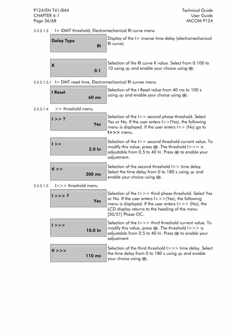
P124/EN T41/B44 Technical Guide CHAPTER 4-1 User Guide Page 36/68 MiCOM P124
3.5.5.1.3 I> IDMT threshold, Electromechanical RI curve menu
Delay Type RI
Display of the I> inverse time delay (electromechanical RI curve)
K 0.1
Selection of the RI curve K value. Select from 0.100 to 10 using # and enable your choice using '.
3.5.5.1.3.1 I> DMT reset time, Electromechanical RI curves menu
t Reset 60 ms
Selection of the t Reset value from 40 ms to 100 s using # and enable your choice using '.
3.5.5.1.4 >> threshold menu
I >> ? Yes
Selection of the I>> second phase threshold. Select Yes or No. If the user enters I>>(Yes), the following menu is displayed. If the user enters I>> (No) go to I>>> menu.
I >> 2.0 In
Selection of the I>> second threshold current value. Tomodify this value, press '. The threshold I>>> is adjustable from 0.5 to 40 In. Press ' to enable your adjustment.
tI >> 300 ms
Selection of the second threshold I>> time delay. Select the time delay from 0 to 180 s using # and enable your choice using '.
3.5.5.1.5 I>>> threshold menu
I >>> ? Yes
Selection of the I>>> third phase threshold. Select Yesor No. If the user enters I>>>(Yes), the following menu is displayed. If the user enters I>>> (No), the LCD display returns to the heading of the menu [50/51] Phase OC.
I >>> 10.0 In
Selection of the I>>> third threshold current value. To modify this value, press '. The threshold I>>> is adjustable from 0.5 to 40 In. Press ' to enable your adjustment
tI >>> 110 ms
Selection of the third threshold I>>> time delay. Selectthe time delay from 0 to 180 s using # and enable your choice using '.

Technical Guide P124/EN T41/B44 User Guide CHAPTER 4-1 MiCOM P124 Page 37/68
3.5.5.2 [50N/51N] E/Gnd sub-menu
PROTECTION G1 Heading of the PROTECTION menu.
[50N/51N] E/Gnd Heading of the [50N/51N] E/Gnd sub-menu
Ie> ? Yes
Selection of the first earth threshold (Ie>). Select Yes or No. If the If the user enters Ie>(Yes), the following menu is displayed. If the user user enters > (No), go to Ie>> menu
le > 0.01 I0n
Displays the current threshold value Ie>. To modify thisvalue, press '. The threshold Ie> is adjustable from : 0.002 to 1 Ien (0.002 to 1 Ien Range) 0.01 to 1 Ien (0.01 to 8 Ien Range) 0.1 to 25 Ien (0.1 to 40 Ien Range) Press ' to enable your adjustment.
Delay Type DMT
Selection of the Ie> threshold time delay type. Select (DMT for definite time, IDMT for inverse time curves, RI for the electromechanical inverse time curve and LABOR.* for Laborelec curves) using # and enable your choice using '. *Note: available for 0.01 to 8 Ien range only.
3.5.5.2.1 Ie> DMT threshold menu
Delay Type DMT
Display of the Ie> DMT time delay.
tIe > 100 ms
Selection of the Ie> time delay. Select the time delay from 0 to 180 s using # and enable your choice using '.
3.5.5.2.2 Ie> IDMT threshold, IEC or IEEE/ANSI curves menu
Delay Type DMT
Display of the Ie> inverse time delay (IEC or IEEE/ANSI curves).
Idmt IEC SI
Selection of the Ie> curve. Select from IEC SI, IEC STI, IEC VI, IEC EI, IEC LTI, CO2, IEEE MI, CO8, IEEE VI, IEEE EI, or IEC RC, using # and enable your choice using the key '.
Tms 0.025
Selection of the selected curve Tms value. Select from 0.025 to 1.5 using # and enable your choice using '.

P124/EN T41/B44 Technical Guide CHAPTER 4-1 User Guide Page 38/68 MiCOM P124
3.5.5.2.2.1 Ie> DMT reset time, IEC curves menu
t Reset 60 ms
Selection of the t Reset value from 40 ms to 100 s using # and enable your choice using '.
3.5.5.2.2.2 Ie> DMT reset time, ANSI curves menu
Type Tempo Reset DMT
Selection of the type of reset time delay. Select between DMT (Definitive Time) and IDMT (Inverse Time) using # and enable your choice using '.
t Reset 60 ms
Selection of the t Reset value associated with the DMT reset time choice. Select from 40 ms to 100 s using # and enable your choice using '.
3.5.5.2.2.3 Ie> IDMT reset time, ANSI curves menu
Type Tempo Reset IDMT
Selection of the type of reset time delay. Select between DMT (Definitive Time) and IDMT (Inverse Time) using # and enable your choice using '.
Rtms 0.025
Selection of the Rtms value associated with the IDMT reset time choice. Select from 0.025 to 1.5 using # and enable your choice using '.
3.5.5.2.3 Ie> IDMT threshold, Electromechanical RI curve menu
Delay type RI
Display of the Ie> inverse time delay (electromechanical RI curve).
K 0.1
Selection of the RI curve K value. Select from 0.100 to 10 using # and enable your choice using '.
3.5.5.2.3.1 Ie> DMT reset time, RI curves menu
t Reset 60 ms
Selection of the t Reset value from 40 ms to 100 s using # and enable your choice using '.
3.5.5.2.4 Ie> threshold, LABORELEC curve
Delay Type LABOR.
Display of the Ie> inverse time delay type LABORELEC
Idmt 1
Selection of the associated curve. Select curve 1, curve 2 or curve 3.
t Reset 40 ms
Selection of the t Reset value associated to the LABORELEC curve. Select from 40 ms to 100 s using ' and enable your choice using '.

Technical Guide P124/EN T41/B44 User Guide CHAPTER 4-1 MiCOM P124 Page 39/68
3.5.5.2.5 Ie>> threshold menu
Ie>> ? Yes
Selection of the Ie>> second earth threshold. Select Yes or No. If the user enters Ie>>(Yes), the following menu is displayed. If the user enters>> (No) go to Ie>>> menu
Ie>> 0.1 I0n
Selection of the Ie>> second threshold current value. To modify this value, press '. The threshold Ie>> is adjustable from : 0.002 to 1Ien (0.002 to 1 Ien Range) 0.01 to 8 Ien (0.01 to 8 Ien Range) 0.5 to 40 Ien (0.1 to 40 Ien Range) Press ' to validate your adjustment.
tIe>> 300 ms
Selection of the second threshold Ie>> time delay. Select the time delay from 0 to 150 s using # and validate your choice using '.
3.5.5.2.6 Ie>>> threshold menu
Ie>>> ? Yes
Selection of the Ie>>> third earth threshold. Select Yes or No. If the user validates Ie>>>(Yes), the following menu is displayed. If the user enters Ie>>> (No), the LCD display returns to the heading of the menu [50N/51N] E/Gnd.
Ie>>> 1.0 I0n
Selection of the Ie>>> third threshold current value.The threshold Ie>> is adjustable from : 0.002 to 1Ien (0.002 to 1 Ien Range) 0.01 to 8 Ien (0.01 to 8 Ien Range) 0.5 to 40 Ien (0.1 to 40 Ion Range) Press ' to validate your adjustment.
tIe>>> 300 ms
Selection of the third threshold Ie>>> time delay. Select the time delay from 0 to 180 s using # and validate your choice using '.
3.5.5.3 [46] NEGATIVE Phase SEQUENCE I2> sub-menu
PROTECTION G1 Heading of the PROTECTION menu.
[46] Neg Seq OC Heading of the [46] NEGATIVE Phase SEQUENCE I2>sub-menu.
I2 > ? Yes
Selection of the negative phase sequence overcurrent function. Select Yes or No. If the user validates (Yes), the following menu is displayed. If the user does not validate (No), no menu is activated.

P124/EN T41/B44 Technical Guide CHAPTER 4-1 User Guide Page 40/68 MiCOM P124
I2 > 0.1 In
Displays the negative phase sequence threshold value I2>. To modify this value, press '. The threshold I2> is adjustable from 0.01 to 40 In step of 0.01 In. Press ' to validate your adjustment.
Delay Type DMT
Selection of the I2> threshold time delay type. Select (DMT for independent time, IDMT for inverse time curves, RI for the electromechanical inverse time curve) using # and validate your choice using '.
3.5.5.3.1 I2> DMT threshold menu
Delay Type DMT
Display of the I2> DMT time delay.
t I2 > 100 ms
Selection of the I2> time delay. Select the time delay from 0 to 150 s using # and validate your choice using '.
3.5.5.3.2 I2> IDMT threshold, IEC or IEEE/ANSI curves menu
Delay Type IDMT
Display of the I2> inverse time delay (IEC or IEEE/ANSIcurves).
Curve IEC SI
Selection of the I2> curve. Select from IEC SI, IEC STI, IEC VI, IEC EI, IEC LTI, CO2, IEEE MI, CO8, IEEE VI, IEEE EI using # and validate your choice using the key '.
Tms 0.025
Selection of the selected curve Tms value. Select from 0.025 to 1.5 using # and validate your choice using '.
3.5.5.3.2.1 I2> DMT reset time, IEC curves menu
t Reset 60 ms
Selection of the t Reset value from 40 ms to 100 s using # and validate your choice using '.
3.5.5.3.2.2 I2> DMT reset time, ANSI curves menu
Type Tempo Reset DMT
Selection of the type of reset time delay. Select between DMT (Definitive Time) and IDMT (Inverse Time) using # and validate your choice using '.
t Reset 60 ms
Selection of the t Reset value associated with the DMT reset time choice. Select from 40 ms to 100 s using # and validate your choice using '.

Technical Guide P124/EN T41/B44 User Guide CHAPTER 4-1 MiCOM P124 Page 41/68
3.5.5.3.2.3 I2> IDMT reset time, ANSI curves menu
Type Tempo Reset IDMT
Selection of the type of reset time delay. Select between DMT (Definitive Time) and IDMT (Inverse Time) using # and validate your choice using '.
Rtms 0.025
Selection of the Rtms value associated with the IDMT reset time choice. Select from 0.025 to 1.5 using # and validate your choice using '.
3.5.5.3.3 I2> IDMT threshold, Electromechanical RI curve menu
Delay Type RI
Display of the I2> inverse time delay (electromechanical RI curve).
K 0.1
Selection of the RI curve K value. Select from 0.100 to 10 using # and validate your choice using '.
3.5.5.3.3.1 I2> DMT reset time, RI curves
t Reset 60 ms
Selection of the t Reset value from 40 ms to 100 s using # and validate your choice using '.

P124/EN T41/B44 Technical Guide CHAPTER 4-1 User Guide Page 42/68 MiCOM P124
3.5.5.4 [49] Therm OL sub-menu
PROTECTION G1 Heading of the PROTECTION menu.
[49] Therm OL Heading of the [49] Therm OL (Thermal Overload) sub-menu
Therm OL ? Yes
Selection of the thermal overload function. Select Yes or No. If the user enters Yes, the following menu is displayed. If the user enters No, no menu content is displayed.
Iθ > 0.3 In
Displays the thermal current threshold value Iθ>. To modify this value, press '. The threshold Iθ> is adjustable from 0.2 to 3.2 In step of 0.01. Press ' to validate your choice.
Te 1 mn
Displays the Te thermal time constant associated with the thermal overload formula. To modify this value, press '. The time constant Te is adjustable from 1 min to 200 min, step of 1 min. Press ' to validate your adjustment.
k 1.05
Displays the k factor associated with the thermal overload function. To modify this value, press '. k factor is adjustable from 1 to 1.5, step of 0.01. Press ' to validate your adjustment.
θ Trip 100%
Displays the percentage applicable to the thermal overload trip threshold. To modify this value, press . θ Trip is adjustable from 50 % to 200 % step of 1%. Press ' to validate your adjustment.
θ Alarm ? Yes
Selection of the thermal overload alarm function. SelectYes or No. If the user validates Yes, the following menu is displayed. If the user validate No, refer to the THERMAL OVERLOAD sub-menu.
θ Alarm 100%
Displays the percentage applicable to the thermal overload alarm threshold. To modify this value, press '. θ Trip is adjustable from 50 % to 200 % step of 1%. Press ' to validate your adjustment.

Technical Guide P124/EN T41/B44 User Guide CHAPTER 4-1 MiCOM P124 Page 43/68
3.5.5.5 [37] UNDERCURRENT I< sub-menu
PROTECTION G1 Heading of the PROTECTION menu.
[37] Under Current
Heading of the [37] Under-Current sub-menu.
I < ? Yes
Selection of the undercurrent function. Select Yes or No. If the user validates (Yes), the following menu is displayed. If the user does not validate (No), no menu points is activated.
I < 20 %
Displays the undercurrent threshold value I<. To modify this value, press '. The threshold I< is adjustable from 2 % to 100 % In, step of 1 %. Press ' to validate your adjustment.
tI < 100 ms
Selection of the tI< time delay. Select the time delay from 0 to 180 s.
3.5.5.6 [79] AUTORECLOSE sub-menu
PROTECTION G1 Heading of the PROTECTION menu.
[79] Autoreclose Heading of the [79] AUTORECLOSER sub-menu
Autoreclose ? Yes
Selection of the autoreclose function. Select Yes or No. If the user validates (Yes), the following menu is displayed. If the user does not validate (No), no menu is activated.
Ext CB Fail ? Yes
Selection of the external circuit breaker failure function associated with the autorecloser function. Select Yes or No. If the user validates (Yes), the following menu is displayed. If the user does not validate (No), the Ext Block sub menu is activated.

P124/EN T41/B44 Technical Guide CHAPTER 4-1 User Guide Page 44/68 MiCOM P124
3.5.5.6.1 [79] EXTERNAL CB FAILURE
Ext CB Fail Yes
Allows the use of a dedicated input (CB FLT) to inform the autorecloser function of the state (failure or operational) of the CB.
Ext CB Fail Time 10 ms
Selection of the external CB failure time delay tCFE. Select the time delay from 10 ms to 600 s using #. Validate your choice using '.
3.5.5.6.2 [79] EXTERNAL BLOCKING
Ext Block ? No
Allows the use of a dedicated input (Block_79) to block the autorecloser function.
3.5.5.6.3 [79] DEAD and RECLAIM TIMES
Dead Time tD1 150 ms
Selection of the First Cycle Dead Time (tD1) value associated with the autoreclose function. Select from 10 ms to 300 s step of 10 ms using # and validate your choice using '.
Dead Time tD2 1.5 s
Selection of the Second Cycle Dead Time (tD2) value associated with the autoreclose function. Select from 10 ms to 300 s step of 10 ms using # and validate your choice using '.
Dead Time tD3 10 s
Selection of the Third Cycle Dead Time (tD3) value associated with the autoreclose function. Select from 10 ms to 600 s step of 10 ms using # and validate your choice using '.
Dead Time tD4 10 s
Selection of the Fourth Cycle Dead Time (tD4) value associated with the autoreclose function. Select from 10 ms to 600 step of 10 ms using # and validate your choice using '.
Reclaim Time tR 10 s
Selection of the Reclaim Time (tR) value associated with the autoreclose function. Select from 20 ms to 600 s step of 10 ms using # and validate your choice using '.
Inhib Time tI 520 ms
Selection of the Inhibit Time (tI) value associated with the autoreclose function (following a manual CB closure). Select from 20 ms to 600 s step of 10 ms using # and validate your choice using '.
Phase Cycles 3
Selection of the number of cycles associated with the phase autoreclose function. Select from 0 to 4 using # and validate your choice using '.

Technical Guide P124/EN T41/B44 User Guide CHAPTER 4-1 MiCOM P124 Page 45/68
E/Gnd Cycles 2
Selection of the number of cycles associated with the earth autoreclose function. Select from 0 to 4 using # and validate your choice using '.
CYCLES 4321 tI > 1101
0 = no action on autorecloser: definitive trip 1 = trip on tI> pick-up, followed by reclosing cycle 2 = no trip on tI> pick-up
CYCLES 4321 tI >> 1211
0 = no action on autorecloser: definitive trip 1 = trip on tI>> pick-up, followed by reclosing cycle 2 = no trip on tI>> pick-up
CYCLES 4321 tI >>> 1110
0 = no action on autorecloser: definitive trip 1 = trip on tI>>> pick-up, followed by reclosing cycle 2 = no trip on tI>>> pick-up
CYCLES 4321 tIe > 0111
0 = no action on autorecloser: definitive trip 1 = trip on tIe> pick-up, followed by reclosing cycle 2 = no trip on tIe> pick-up
CYCLES 4321 tIe >> 1121
0 = no action on autorecloser: definitive trip 1 = trip on tIe>> pick-up, followed by reclosing cycle 2 = no trip on tIe>> pick-up
CYCLES 4321 tIe >>> 1111
0 = no action on autorecloser: definitive trip 1 = trip on tIe>>> pick-up, followed by reclosing cycle
CYCLES 4321 tAux1 1112
0 = no action on autorecloser: definitive trip 1 = trip on tAux1 pick-up, followed by reclosing cycle 2 = no trip on t Aux1 pick-up
CYCLES 4321 tAux2 0111
0 = no action on autorecloser: definitive trip 1 = trip on t Aux2 pick-up, followed by reclosing cycle 2 = no trip on tAux2 pick-up

P124/EN T41/B44 Technical Guide CHAPTER 4-1 User Guide Page 46/68 MiCOM P124
3.5.6 AUTOMAT. CTRL Menu
The AUTOMAT. CTRL Menu makes it possible to programme the various automation functions included in the MiCOM P124.
The various sub-menus are :
⇒ Trip Commands
⇒ Latch Functions (associated to trip relay RL1)
⇒ Blocking logic 1
⇒ Blocking Logic 2
⇒ Logic Select. 1
⇒ Logic Select. 2
⇒ Outputs Relays (RL2 to RL6)
⇒ Latch output relay (RL2 to RL6)
⇒ Inputs
⇒ Broken Conductor
⇒ Cold load PU
⇒ CB Fail
⇒ CB Supervision
To access the AUTOMAT. CTRL Menu, press # then the key $ six times.
3.5.6.1 Trip Commands sub-menu
This sub-menu makes it possible to assign to the trip output (RL1) part or all the selected thresholds.
AUTOMAT.CTRL Heading of the AUTOMAT.CTRL Menu.
Trip Commands Heading of the Trip ORDER sub-menu.
Trip tI> Yes
Allocation of the first phase time delay overcurrent threshold (tI>) to the trip output (select Yes or No). If the user validates Yes, the trip output relay (RL1) shall be activated at the end of the time delay tI>. If the user validates No, the trip output relay (RL1) shall never be activated, even at the end of the time delay tI>.
Trip tI>> Yes
Allocation of the second phase time delay overcurrent threshold (tI>>) to the trip output. Select Yes or No.

Technical Guide P124/EN T41/B44 User Guide CHAPTER 4-1 MiCOM P124 Page 47/68
Trip tI>>> Yes
Allocation to the third phase time delay overcurrent threshold (tI>>>) to the trip output. Select Yes or No.
Trip tIe> Yes
Allocation of the first earth time delay overcurrent threshold (tIe>) to the trip output. Select Yes or No.
Trip tIe>> Yes
Allocation of the second earth time delay overcurrent threshold (tIe>>) to the trip output. Select Yes or No.
Trip tIe>>> Yes
Allocation of the third earth time delay overcurrent threshold (tIe>>>) to the trip output. Select Yes or No.
Trip tI < No
Allocation of the under-current threshold to the trip output Select Yes or No.
Trip tI2 > Yes
Allocation of the delayed negative phase sequence overcurrent threshold (tI2>) to the trip output. Select Yes or No.
Trip Thermal θ Yes
Allocation of the thermal overload Trip information (θ Trip) to the trip output. Select Yes or No.
Trip Brkn.Cond No
Allocation of the broken conductor detection to the trip output. Select Yes or No.
Trip t Aux 1 Yes
Allocation of the delayed auxiliary input Aux 1 to the trip output. Select Yes or No.
Trip t Aux 2 Yes
Allocation of the delayed auxiliary input Aux 2 to the trip output. Select Yes or No.

P124/EN T41/B44 Technical Guide CHAPTER 4-1 User Guide Page 48/68 MiCOM P124
3.5.6.2 Latch Functions Sub-Menu
This sub-menu makes it possible to latch the trip output relay (RL1) associated with one or several thresholds after the cause has disappeared.
AUTOMAT. CTRL Heading of the AUTOMAT. CTRL menu.
Latch Functions Heading of the Latch functions associated to the trip output relay RL1 sub-menu.
Latch tI> Yes
Latch of the trip output relay (RL1) associated with the first phase time delay overcurrent threshold (tI>) (select Yes or No). If the user validates Yes, RL1 shall be latched after tI> disappeared. If the user validates No, RL1 shall drop out after tI>.
Latch tI>> Yes
Latch of the trip output relay (RL1) associated with the second phase time delay overcurrent threshold (tI>>) (select Yes or No). If the user validates Yes, RL1 shall be latched after tI>> disappeared. If the user validates No, RL1 shall drop out after tI>>.
Latch tI>>> Yes
Latch of the trip output relay (RL1) associated with the third phase time delay overcurrent threshold (tI>>>) (select Yes or No). If the user validates Yes, RL1 shall be latched after tI>>> disappeared. If the user validates No, RL1 shall drop out after tI>>>.
Latch tIe> Yes
Latch of the trip output relay (RL1) associated with the first earth time delay overcurrent threshold (tIe>) (selectYes or No). If the user validates Yes, RL1 shall be latched after tIe> disappeared. If the user validates No, RL1 shall drop out after tIe>.
Latch tIe>> Yes
Latch of the trip output relay (RL1) associated with the second earth time delay overcurrent threshold (tIe>>) (select Yes or No). If the user validates Yes, RL1 shall be latched after tIe>> disappeared. If the user validates No, RL1 shall drop out after tIe>>.
Latch tIe>>> Yes
Latch of the trip output relay (RL1) associated with the third earth time delay overcurrent threshold (tIe>>>) (select Yes or No). If the user validates Yes, RL1 shall be latched after tIe>>> disappeared. If the user validates No, RL1 shall drop out after tIe>>>.
Latch tI < Yes
Latch of the trip output relay (RL1) associated with the time delay undercurrent threshold (tI<) (select Yes or No). If the user validates Yes, RL1 shall be latched after tI< disappeared. If the user validates No, RL1 shall drop out after tI<.

Technical Guide P124/EN T41/B44 User Guide CHAPTER 4-1 MiCOM P124 Page 49/68
Latch tI2 > Yes
Latch of the trip output relay (RL1) associated with the time delay negative phase overcurrent threshold (tI2>) (select Yes or No). If the user validates Yes, RL1 shall be latched after tI2> disappeared. If the user validatesNo, RL1 shall drop out after tI2>.
Latch Thermal θ Yes
Latch of the trip output relay (RL1) associated with the thermal overload trip information (θ trip) (select Yes or No). If the user validates Yes, RL1 shall be latched after θ trip disappeared. If the user validates No, RL1 shall drop out after θ trip.
Latch Brkn.Cond No
Latch of the trip output relay (RL1) associated with the broken conductor function (Latch Brkn. Cond) (select Yes or No). If the user validates Yes, RL1 shall be latched after Latch Brkn. Cond. Information disappeared. If the user validates No, RL1 shall drop out after Latch Brkn. Cond.
Latch t Aux 1 Yes
Latch of the trip output relay (RL1) associated with the delayed auxiliary input (Aux 1) (select Yes or No). If the user validates Yes, RL1 shall be latched after tAux 1 disappeared. If the user validates No, RL1 shall drop out after tAux 1.
Latch t Aux 2 Yes
Latch of the trip output relay (RL1) associated with the delayed auxiliary input (Aux 2) (select Yes or No). If the user validates Yes, RL1 shall be latched after tAux 2 disappeared. If the user validates No, RL1 shall drop out after tAux 2.
3.5.6.3 Blocking Logic sub-menu
The Blocking Logic sub-menu is labelled as Blocking Logic 1 t and Blocking Logic 2 t for the dual powered MiCOM P124 relays.
The Blocking Logic (1) t allows blocking of each time delayed stage by the input assigned to the Blocking Logic function (1) BLOCK LG 1 (refer to inputs menu).
The same Blocking Logic (2) t submenu allows blocking of each time delayed stage by the input assigned to the Blocking Logic function (2) BLOCK LG 2 (refer to inputs menu).
AUTOMAT. CTRL Heading of the AUTOMAT. CTRL menu.
Blocking Logic Heading of the Blocking Logic sub-menu.
Block 1 tI> Yes
Blocking logic of the first phase time delay overcurrent threshold (tI>) (select Yes or No). If the user validates Yes, the first threshold shall be locked on the transition (logic state 1) of the Logic "Blk log" logic input. If the user validates No, the transition of the "Blk log" logic input shall not alter the first phase threshold tI>.

P124/EN T41/B44 Technical Guide CHAPTER 4-1 User Guide Page 50/68 MiCOM P124
Block 1 tI>> Yes
Blocking logic of the second phase time delay overcurrent threshold (tI>>). Select Yes or No.
Block 1 tI>>> Yes
Blocking logic of the third phase time delay overcurrent threshold (tI>>>) Select Yes or No.
Block 1 tIe> Yes
Blocking logic of the first earth time delay overcurrent threshold (tIe>). Select Yes or No.
Block 1 tIe>> Yes
Blocking logic of the second earth time delay overcurrent threshold (tIe>>). Select Yes or No.
Block 1 tIe>>> Yes
Blocking logic of the third earth time delay overcurrent threshold (tIe>>>). Select Yes or No.
Block 1 tI2 > Yes
Blocking logic of the time delay negative phase sequence overcurrent threshold (tI2>) to the trip output. Select Yes or No.
Block 1 Thermal θ Yes
Blocking logic of the thermal state calculation. Select Yes or No.
Block 1 Brkn.Cond No
Blocking logic of the broken conductor function Select Yes or No.
Block 1 t Aux 1 No
Blocking logic of the time delay of the auxiliary input Aux 1. Select Yes or No.
Block 1 t Aux 2 No
Blocking logic of the time delay of the auxiliary input Aux 2. Select Yes or No.

Technical Guide P124/EN T41/B44 User Guide CHAPTER 4-1 MiCOM P124 Page 51/68
3.5.6.4 Logic Select sub-menu
The Logic Select. 1 sub-menu allows the user to delay the 2nd and 3rd time delayed stages through the logic input assigned to the Log Sel 1 function (INPUTS sub-menu).
The Logic Select. 2 sub-menu allows the user to delay the 2nd and 3rd time delayed stages through the logic input assigned to the Log Sel 2 function (INPUTS sub-menu).
AUTOMAT. CTRL Heading of the AUTOMAT. CTRL menu.
Logic Select. 1 Heading of the Logic Select. 1 sub-menu.
Sel1 tI>> Yes
Logic selectivity of the second phase time delay overcurrent threshold (tI>>) (select Yes or No). If the user validates Yes, operation of the second threshold shall be delayed for tSel1 on the transition (logic state 1) of the "Log Sel 1" logic input. If the user validates No, the transition of the "Log Sel 1" logic input shall notalter the second phase threshold tI>>.
Sel1 tI>>> Yes
Logic selectivity of the third phase time delay overcurrent threshold (tI>>>) Select Yes or No.
Sel1 tIe>> Yes
Logic selectivity of the second earth time delay overcurrent threshold (tIe>>). Select Yes or No.
Sel1 tIe>>> Yes
Logic selectivity of the third earth time delay overcurrent threshold (tIe>>>). Select Yes or No.
t Sel1 150 ms
Displays the selective scheme logic time delay t Sel1. To modify this value, press '. The t Sel1 is adjustable from 0 ms to 150 s by step of 10 ms. Press ' to validate your adjustment.

P124/EN T41/B44 Technical Guide CHAPTER 4-1 User Guide Page 52/68 MiCOM P124
3.5.6.5 Outputs Relays sub-menu
This sub-menu makes it possible to allocate to each logic output (excepted Watchdog RL0 and Tripping RL1 refer to Trip Commands submenu) the various thresholds (instantaneous and/or time delay).
• MiCOM P124 dual-powered : allows 5 outputs, RL2 to RL6
AUTOMAT. CTRL Heading of the AUTOMAT.CTRL menu.
Output Relays Heading of the Output Relays sub-menu.
Trip 65432 00101
Allocation of trip orders to the output relays RL2 to RL6 (copies the trip contact onto one or several selected relays). To allocate this information to the output relay(s), press ', then allocate to the desired output relay the value 1using #. Repeat the operation on the other output relays if desired, then validate using '.
I > 65432 00101
Allocation of the first phase instantaneous overcurrent threshold (I>) to the output relays RL2 to RL6. Select output relays.
tI > 65432 00101
Allocation of the first phase time delay overcurrent threshold (tI>) to the output relays RL2 to RL6. Select output relays.
I >> 65432 00101
Allocation of the second phase instantaneous overcurrent threshold (I>>) to the output relays RL2 to RL6.
tI >> 65432 00101
Allocation of the second phase time delay overcurrent threshold (tI>>) to the output relays RL2 to RL6. Select output relays.
I >>> 65432 01101
Allocation of the third phase instantaneous overcurrent threshold (I>>>) to the output relays RL2 to RL6. Select output relays.
tI >>> 65432 00101
Allocation of the third phase time delay overcurrent threshold (tI>>>) to the output relays RL2 to RL6. Select output relays .

Technical Guide P124/EN T41/B44 User Guide CHAPTER 4-1 MiCOM P124 Page 53/68
Ie > 65432 00101
Allocation of the first earth instantaneous overcurrent threshold (Ie>) to the output relays RL2 to RL6. Select output relays .
tIe > 65432 00101
Allocation of the first earth time delay overcurrent threshold (tIe>) to the output relays RL2 to RL6. Select output relays.
Ie >> 65432 00101
Allocation of the second earth instantaneous overcurrent threshold (Ie>>) to the output relays RL2 toRL6.
tIe >> 65432 00101
Allocation of the second earth time delay overcurrent threshold (tIe>>) to the output relays RL2 to RL6. Select output relays.
Ie >>> 65432 00101
Allocation of the third earth instantaneous overcurrent threshold (Ie>>>) to the output relays RL2 to RL6. Select output relays.
tIe >>> 65432 00101
Allocation of the third earth time delay overcurrent threshold (tIe>>>) to the output relays RL2 to RL6. Select output relays.
tI < 65432 00101
Allocation of the minimum current time delay threshold (tI<) to the output relays RL2 to RL6. Select output relays.
tI2 > 65432 00101
Allocation of the negative phase sequence overcurrent time delay threshold (tI2>) to the output relays RL2 to RL6.
Therm. 65432 Alarm 00101
Allocation of the thermal alarm threshold to the output relays RL2 to RL6. Select output relays.
Therm. 65432 Trip 00101
Allocation of the thermal trip threshold to the output relays RL2 to RL6. Select output relays.
CB Alarm 65432 00101
Allocation of the Circuit Breaker Alarm function to the output relays (CB OPEN Nb, SUM An, Tripping and closing Time) RL2 to RL6. Select output relays.

P124/EN T41/B44 Technical Guide CHAPTER 4-1 User Guide Page 54/68 MiCOM P124
52 Fail 65432 00101
Allocation of the Circuit Breaker Trip Supervision Failure function to the output relays RL2 to RL6. Select output relays.
Brkn. 65432 Cond 01101
Allocation of the broken conductor function to the output relays RL2 to RL6. Select output relays.
CB Fail 65432 01101
Allocation of the circuit breaker failure function to the output relays RL2 to RL6. CB Fail = CB not open at the end of tBF timer
CB 65432 Close 00101
Allocation of the circuit breaker closing order to the output relays RL2 to RL6. Select output relays.
t Aux 1 65432 00101
Allocation of the delayed auxiliary input Aux 1 to the output relays RL2 to RL6. Select output relays.
t Aux 2 65432 00101
Allocation of the delayed auxiliary input Aux 2 to the output relays RL2 to RL6. Select output relays.
79 Run 65432 00101
Allocation of the "autorecloser in progress" information to the output relays RL2 to RL6. Select output relays.
79 Trip 65432 00101
Allocation of the autorecloser final trip function to the output relays RL2 to RL6. Select output relays.
Active 65432 Group 10000
Allocation of the Active Group indication to the output relays RL2 to RL6. Select output relays.

Technical Guide P124/EN T41/B44 User Guide CHAPTER 4-1 MiCOM P124 Page 55/68
3.5.6.6 Latch of the Output relays RL2 to RL6
This sub-menu makes it possible to latch the auxiliary output relays, relay by relay.
AUTOMAT. CTRL Heading of the AUTOMAT.CTRL menu. To gain access to the menu, press $, % 6 times.
Latch Output Relays
Heading of the Latch Output Relays sub-menu. To gain access to the sub-menu points, press $.
Output 2 No
Latch of the auxiliary output relay RL2. Select Yes or No.
Output 3 Yes
Latch of the auxiliary output relay RL3. Select Yes or No.
Output 4 Yes
Latch of the auxiliary output relay RL4. Select Yes or No.
Output 5 Yes
Latch of the auxiliary output relay RL5. Select Yes or No.
Output 6 No
Latch of the auxiliary output relay RL6. Select Yes or No.
Output 7 Yes
Latch of the auxiliary output relay RL7. Select Yes or No.
Output 8 No
Latch of the auxiliary output relay RL8. Select Yes or No.

P124/EN T41/B44 Technical Guide CHAPTER 4-1 User Guide Page 56/68 MiCOM P124
3.5.6.7 Inputs sub-menu
This sub-menu makes it possible to allocate to each logic input either a label or an automation function, following the table :
Label abstract Label signification
None No allocation
Unlatch Delocking the latching of the outputs
52 a Position of the circuit breaker (open)
52 b Position of the circuit breaker (close)
CB FLT External failure information from the CB
Aux 1 Allocation to the input the external information Aux 1
Aux 2 Allocation to the input the external information Aux 2
Blk Log (1) Blocking logic 1
Blk Log 2 Blocking logic 2
Strt Dist Starting of the disturbance recording function
Cold L PU Cold load pick up alloction
Log Sel 1 Logic selectivity 1
Log Sel 2 Logic selectivity 2
Change set Change of setting group (default setting group 1)
θ Reset Reset of the thermal state
Block-79 Blocking of the autorecloser function [79]
Trip Circ Trip circuit supervision input
Start tBf Starting of the breaker failure timer
AUTOMAT. CTRL Heading of the AUTOMAT.CTRL menu.
Inputs Heading of the Inputs sub-menu.
Input 1 O/O
Allocation of logic input 1. To allocate labels to logic input 1, press ' then with # $ select the desired label from the available list, then validate your choice using '.
Input 2 BLC LG
Allocation of logic input 2. To allocate labels to logic input 2, press ' then with # $ select the desired label from the available list, then validate your choice using '.

Technical Guide P124/EN T41/B44 User Guide CHAPTER 4-1 MiCOM P124 Page 57/68
Input 3 AUX1
Allocation of logic input 3. To allocate labels to logic input 3, press ' then with # $ select the desired label from the available list, then validate your choice using '.
Input 4 C.L.S
Allocation of logic input 4. To allocate labels to logic input 4, press ' then with # $ select the desired label from the available list, then validate your choice using '.
Input 5 RAZ TH
Allocation of logic input 5. To allocate labels to logic input 5, press ' then with # $ select the desired label from the available list, then validate your choice using '.
Aux1 Time t Aux1 300 ms
Displays the time delay t Aux 1 associated with the logic input Aux1. To modify this value, press '. The t Aux 1 is adjustable from 0 ms to 200 s by step of 10 ms, then validate your choice using '.
Aux2 Time t Aux2 8 s
Displays the time delay t Aux 2 associated with the logic input Aux 2. To modify this value, press '. The t Aux 2 is adjustable from 0 ms to 200 s by step of 10 ms, then validate your choice using '.
3.5.6.8 BROKEN CONDUCTOR sub-menu
AUTOMAT. CTRL Heading of the AUTOMAT. CTRL menu.
Broken Cond. Heading of the BROKEN CONDUCTOR sub-menu.
Brkn. Cond. ? Yes
Selection of the broken conductor function. Select Yes or No. If the user validates (Yes), the following menu is displayed. If the user validates (No), the broken conductor function is inactive.
Brkn.Cond Time tBC 32 s
Display the broken conductor time delay tBC. To modify this value, press '. The tBC is adjustable from 1 to 14400 s with step of 1 s. Press ' to validate your adjustment
Ratio I2/I1 20%
Display the broken conductor threshold. This threshold is a ratio between the negative phase sequence and the positive phase sequence current. To modify this value, press '. The I2/I1 ratio is adjustable from 20 to 100% by step of 1%. Press ' to validate your adjustment

P124/EN T41/B44 Technical Guide CHAPTER 4-1 User Guide Page 58/68 MiCOM P124
3.5.6.9 COLD LOAD PICK-UP sub-menu
AUTOMAT. CTRL Heading of the AUTOMAT.CTRL menu.
Cold Load PU Heading of the Cold Load PU sub-menu.
Cold Load PU ? Yes
Selection of the cold load pick-up function. Select Yes or No. If the user validates (Yes), the following menu is displayed. If the user does not validate (No), the cold load pick-upfunction is inactive.
Cold Load PU tI> ? Yes
Associate the I> time delay threshold with the cold load pick up function. To modify this choice, press ' and using # allocate the desired threshold to the cold load pick-up function. Validate your choice using '.
Cold Load PU tI>> ? Yes
Associate the I>> time delay threshold with the cold load pick up function. To modify this choice, press ' and using # allocate the desired threshold to the cold load pick up function. Validate your choice using '.
Cold Load PU tI >>> ? Yes
Associated the I>>> time delay threshold to the cold load pick up function. To modify this choice, press ' and using # allocate the desired threshold to the cold load pick up function. Validate your choice using '.
Cold Load PU tIe > ? Yes
Associated the Ie> time delay threshold to the cold load pick up function. To modify this choice, press ' and using # allocate the desired threshold to the cold load pick-up function. Validate your choice using '.
Cold Load PU tIe >> ? Yes
Associated the Ie>> time delay threshold to the cold load pick up function. To modify this choice, press ' and using # allocate the desired threshold to the cold load pick-up function. Validate your choice using '.
Cold Load PU tIe >>> ? Yes
Associated the Ie>>> time delay threshold to the cold load pick up function. To modify this choice, press ' and using # allocate the desired threshold to the cold load pick-up function. Validate your choice using '.

Technical Guide P124/EN T41/B44 User Guide CHAPTER 4-1 MiCOM P124 Page 59/68
COLD LOAD P/UP tI2> ? Yes
Associated the I2> time delay threshold the cold load pick up function. To modify this choice, press ' and using # allocate desired threshold to the cold load start pick up function. Validate your choice using '.
Cold Load PU t Therm. ? Yes
Associated the Thermal overload time delay threshold to the cold load pick up function. To modify this choice,press ' and using # allocate the desired threshold to the cold load pick-up function. Validate your choice using '.
Cold Load PU level 120%
Selection of the cold load pick up percentage scaling value associated with the selected thresholds. Select from 20% to 500% with steps of 1 % using # and validate your choice using '.
Cold Load PU tCL = 2 s
Selection of the cold load pick up time delay. Select from 100 ms to 3600 s with steps of 10 ms using # and validate your choice using '.
3.5.6.10 CIRCUIT BREAKER FAILURE sub-menu
AUTOMAT. CTRL Heading of the AUTOMAT.CTRL menu.
CB Fail Heading of the CB Fail sub-menu.
CB Fail ? Yes
Selection of the circuit breaker failure function. If the user validates (Yes), the next menu is displayed. If the user does not validate (No), the breaker failure function is inactive.
I< 20% In
Display of the I< threshold value which defines the current monitoring band zone. To modify that value, press '. The threshold is settable between 2% and 100%. To confirm the setting, press '.
CB Fail Time tBF 200 ms
Selection of the circuit breaker failure time delay. Select from 30 ms to 10 s with steps of 10 ms using # and validate your choice using '.
Bloc I > ? No
Selection of the blocking function for 1st overcurrent stage assigned to the output relay upon breaker failure. Choose YES or NO.
Bloc Ie > ? No
Selection of the blocking function for 1st earth fault stage assigned to the output relay upon breaker failure. Choose YES or NO.

P124/EN T41/B44 Technical Guide CHAPTER 4-1 User Guide Page 60/68 MiCOM P124
3.5.6.11 CIRCUIT BREAKER SUPERVISION sub-menu
AUTOMAT. CTRL Heading of the AUTOMAT.CTRL menu.
CB Supervision Heading of the CB Supervision sub-menu.
TC Supervision Yes
Selection of the trip circuit supervision function. Select Yes or No. If the user validates (Yes), the function is active. If the user does not validate (No), go to CB Open Time menu. The trip circuit supervision function is inactive.
t Trip Circuit t SUP 3 s
Selection of the Trip circuit supervision timer. Select from 100 ms to 10 s with steps of 10 ms using # Validate your choice using '.
CB Open S'vision Yes
Selection of the CB open operating time supervision function. Select Yes or No. If the user validates (Yes) the following menu is displayed. If the user does not validate (No), go to CB Close menu. The CB open operating time supervision function is inactive.
CB OpenTime 150 ms
Selection of the CB open operating time (tCBO). Select from 50 ms to 1.0 s with steps of 10 ms using #. Validate your choice using '.
CB Close S'vision Yes
Selection of the CB close operating time supervision function. Select Yes or No. If the user validates (Yes), the following menu is displayed. If the user does not validate (No), go to CB.Open Alarm menu. The CB close operating time supervision function is inactive.
CB Close Time 150 ms
Selection of the CB close operating time (tCBC). Select from 50 ms to 1.0 s with steps of 10 ms using #. Validate your choice using '.
CB Open Alarm ? Yes
Selection of the maximum CB operations function. Select Yes or No. If the user validates (Yes), the following menu is displayed. If the user does not validate (No), refer to ΣAmps(n) menu. The CB open maximum number function is inactive.

Technical Guide P124/EN T41/B44 User Guide CHAPTER 4-1 MiCOM P124 Page 61/68
CB Open NB 1500
Selection of the CB open numbers alarm threshold. Select from 0 to 50000 by step of 1 using #. Validate your choice using '.
ΣAmps(n) ? Yes
Selection of the Summation Amps (or square Amps) interrupted by the CB function. Select Yes or No. If the user validates (Yes), the following menu is displayed. If the user does not validate (No), refer to t open pulse menu. The Summation Amps function is inactive.
ΣAmps(n) 3 E6
Selection of the summation Amps (or square Amps) alarm threshold. Select from 0 to 4000 E6 A (or A2) with steps of 1 E6 using #. Validate your choice using '.
n 2
Selection of the type of summation (Amps or square Amps). Select 1 or 2 using #. Validate your choice using '.
t Open Pulse 300 ms
Selection of the tripping pulse time. Select from 100 ms to 5 s with steps of 100 ms using #. Validate your choice using '.
t Close Pulse 500 ms
Selection of the closing time. Select from 100 ms to 5 s with steps of 100 ms using #. Validate your choice using '.

P124/EN T41/B44 Technical Guide CHAPTER 4-1 User Guide Page 62/68 MiCOM P124
3.5.7 RECORDS Menu
The RECORDING menu makes it possible to read the records.
The various sub-menus are :
⇒ CB Monitoring
⇒ Fault record
⇒ Disturb record
⇒ Time peak value
3.5.7.1 CB MONITORING sub-menu
The CB Monitoring sub-menu makes possible to read and clear the parameters and measurements associated to this function.
RECORD Heading the RECORD menu.
CB Monitoring Heading the CB Monitoring sub-menu.
CB Opening Time 83 ms
Display the circuit breaker opening time in ms.
CB Closing Time 100 ms
Display the circuit breaker closing time in ms.
CB Operations RST=[C] 1312
Display the number of opening commands sent by the relay. To clear these values, press !.
Σ Amps (n) RST=[C]
Allows the user to clear the memorised summations of interrupted currents. All 3 phases currents are clear together. To clear these values, press !.
Σ Amps (n) IA 5 E6
Display the summation of the Amps (or square Amps) interrupted by the circuit breaker phase A.
Σ Amps (n) IB 5 E6
Display the summation of the Amps (or square Amps) interrupted by the circuit breaker phase B.

Technical Guide P124/EN T41/B44 User Guide CHAPTER 4-1 MiCOM P124 Page 63/68
Σ Amps (n) IC 5 E6
Display the summation of the Amps (or square Amps) interrupted by the circuit breaker phase C.
3.5.7.2 Fault Record sub-menu
The Fault RECORD sub-menu makes possible to read the various parameters and measurement for each of the five fault store in MiCOM P124 memory.
RECORD Heading of the RECORD menu.
Fault Record Heading of the Fault Record sub-menu.
Record Number 4
Selection of the Fault record number (by selecting either 1, 2, 3, 4 or 5) to be displayed. To modify this fault record number, press ' then using # enter the required number. Validate your choice using '.
Fault Time 12:05:23:42
Display the time of the fault record. The format of the time is HH:MM:ss:msms In this example the fault appeared at 12H am, 05 minutes, 23 seconds and 420 ms.
Fault Date 12/10/99
Display the Date of the fault record. The format of the Date is DD/MM/YY. In this example, the fault appeared on 12 October 1999.
Active Set Group 2
Display the active setting group (1 or 2).
Faulted Phase Phase A
Display the faulty phase for the chosen fault record (NONE, phase A, B, C, EARTH, AB, AC, BC, or ABC).
Threshold I>>
Display the origin of the fault that as generated the trip order.
Magnitude 1200 A
Display the magnitude of the faulty current. This value is the 50/60 Hz amplitude.
IA Magnitude 1200 A
Display the magnitude of the phase A current at the time of the Fault. This value is the 50/60 Hz amplitude.

P124/EN T41/B44 Technical Guide CHAPTER 4-1 User Guide Page 64/68 MiCOM P124
IB Magnitude 500 A
Display the magnitude of the phase B current at the time of the Fault. This value is the 50/60 Hz amplitude.
IC Magnitude 480 A
Display the magnitude of the phase C current at the time of the Fault. This value is the 50/60 Hz amplitude.
In Magnitude 103 A
Display the magnitude of the earth current at the time of the Fault. This value is the 50/60 Hz amplitude.
3.5.7.3 DISTURBANCE RECORD sub-menu
The DISTURBANCE sub-menu makes possible to set the various parameters and thresholds associated to this recording function.
RECORD Heading of the RECORD menu.
Disturb Record Heading of the Disturb Record sub-menu.
Pre-Time 1.3 s
Selection of the disturbance record pre-time. Select from 100 ms to 3s by step of 100 ms using #. Validate your choice using '.
Post-Time 0.2 s
Selection of the disturbance record post-time. Select from 100 ms to 3s by step of 100 ms using # and validate your choice using '.
WARNING : THE TOTAL DISTURBANCE RECORDING TIME IS 3 SECONDS (PRE TIME + POST TIME).
Disturb Rec Trig ON INST.
Selection of start criteria for the disturbance recording function. Select between ON INST. (start on instantaneous thresholds) or ON Trip (start on trip conditions) using # and validate your choice using '.

Technical Guide P124/EN T41/B44 User Guide CHAPTER 4-1 MiCOM P124 Page 65/68
3.5.7.4 Time PEAK VALUE sub-menu
The Time PEAK VALUE sub-menu makes possible to set parameters associated to this function. (Peak and Average values displayed in the Measurements menu).
RECORD Heading of the RECORD menu.
Time Peak Value Heading of the Time Peak Value sub-menu.
Time Window 5 mn
Selection of the time of the window during the peak and average values are stored. Select either 5mn, 10mn, 15mn, 30mn, or 60mn using '. Validate your choice using '.

P124/EN T41/B44 Technical Guide CHAPTER 4-1 User Guide Page 66/68 MiCOM P124
4. WIRING
The external connection diagrams of the MiCOM P124 relays are provided in Appendix 1 of the Technical Guide.
4.1 Current inputs (measurement)
The MiCOM P124 relays have 4 analogue inputs (3 phase current inputs and 1 earth current input). The rated current value of these measurement inputs is either 1A or 5A (must be specified on order).
The rated current is indicated on the front panel of the relay, behind the top flap.
WARNING: THE CONNECTION OF THE EARTH CURRENT INPUT MAY DIFFER DEPENDING ON WHETHER IT IS CONNECTED TO A CORE BALANCED CT OR TO A SUMMATION OF THE 3 PHASE CTs.
Connection to 3 phase CTs and 1 core balanced CT:
Generally, when the relay is used with three phase CTs and one core balanced CT, there is not need to power the relay through the earth channel.
In this case, the core balanced CT can be connected to terminals 47 and 48.
For some phase to earth faults, when some specific cores are used, it can be possible that the fault does not generate a current high enough* to power the relay from only one phase circuit. It will then be necessary to connect the core TC to terminals 55 and 56 in order to power the relay through the earth circuit as well.
*reminder: the MiCOM P124 relay is self-powered from a 0.2 In current on at least one phase.
Connection to 3 phase CTs:
In this case the earth current is derived from the summation of the 3 phase currents.
It is not necessary to power the relay via the earth circuit. The summation of the 3 CTs must be connected to terminals 47 and 48.
Connection to 2 phase CTs and 1 core balanced CT:
In this case it is necessary to power the relay through the earth circuit. The core balanced CT must be connected to terminals 55 and 56.
4.2 Output relays
7 output relays are available on the DUAL-POWERED model.
6 relays are freely programmable (RL1 à RL6), the first relay RL0 being allocated to signalling an equipment Fault (WATCH DOG) :
• All the output relays are of change-over relays (1 common, 1 normally open contact, 1 normaly closed contact). The protection and control functions to which these relays respond can be selected by means of the AUTOMAT. CTRL. Menu.
NOTE : RL1 is the default trip contact. This relay can be programmed for fail-safe operation (Configuration/RL1 output relay menu).
• One watchdog relay with a C/O contact (1 common, 1 normally open, 1 normally closed)

Technical Guide P124/EN T41/B44 User Guide CHAPTER 4-1 MiCOM P124 Page 67/68
WARNING : DURING AUXILIARY POWER SUPPLY FAILURE, AND IN ORDER TO SAVE ENERGY, THE WATCHDOG RELAY IS USED ONLY WHEN THERE IS A 0.4 IN CURRENT ON AT LEAST ONE PHASE. IT IS DE-ENERGISED BELOW THAT CURRENT LEVEL OR WHEN A SOFTWARE OR HARDWARE FAULT IS PRESENT.
Only the relays RL0 and RL1 are functional during an auxiliary power supply failure:
− RL0: from a 0.4 In current on at least one phase,
− RL1: when the relay is not programmed in fail-safe operation. If RL1 is programmed in fail-safe operation, in that case the command of RL1 is blocked as well as the protection function.
4.3 Striker output
The P124 relays are fitted with a striker output used to trip the circuit breaker via a striker device in the absence of an external auxiliary supply.
The 2 terminals to be connected to the striker are polarised:
− + terminal 39
− terminal 41
according to the external connection diagrams provided in Appendix 1 of the Technical Guide.
4.4 RS232 front communication port
MiCOM P124 relays provide the user an RS 232 communication port. This link is dedicated to the MiCOM Setting software MiCOM S1.
Le câble entre le PC et le relais MiCOM doit être équipé de 2 connecteurs Sub D 9 points reliés en point à point.
RS 232 PC port RS 232 Cable
MiCOM P124 end 9 pin male connector
2 2
3 3
5 5
7 7
In case where the battery box MiCOM E1 is used to power the P124 relay, it is placed between the PC and the P124 relay.
4.5 Auxiliary supply
The auxiliary supply of the MiCOM P124 dual powered relays can be either :
• Dc (range 24-60 Vdc or 48-150 Vdc or 130-250 Vdc)
• Ac (100-250 Vac/ 50-60 Hz).
The voltage range is indicated on the front panel, under the top flag.
The power supply must be connected to terminals 33-34 only.

P124/EN T41/B44 Technical Guide CHAPTER 4-1 User Guide Page 68/68 MiCOM P124
4.6 Logic inputs
MiCOM P124 Dual-powered model relays have 5 opto-isolated logic inputs. Each input has its own independent polarity. The voltage range of the inputs is identical to the dc auxiliary supply range of the MiCOM relay (e.g. Uaux = 48-150 Vdc, logic input voltage range = 48-150 Vdc).
On the same MiCOM P124 relay, the user can mixed different voltage level for the logic inputs (e.g. Uaux = 48-150 Vdc, Input 1= 48 Vdc, Input 2-5= 125 Vdc)
The automation operations and signalling functions to which these logic inputs respond can be selected by means of the AUTOMAT. CTRL Menu.
WARNING : THESE LOGIC INPUTS CAN ONLY BE USED WHEN THE MICOM RELAY IS POWERED BY AN EXTERNAL AUXILIARY SUPPLY.
4.7 RS485 rear communication port
All MiCOM P124 Dual-powered relays have an RS485 rear communication port.
The connection of communication is allocated to terminals 29-30-31-32, following the schemes given in the Appendix 1 of the Technical Guide.
WARNING : THE REARPORT COMMUNICATION CAN ONLY BE USED WHEN THE MICOM RELAY IS POWERED BY AN EXTERNAL AUXILIARY SUPPLY.

Technical Guide P124/EN T42/B44 MiCOM P124
CHAPTER 4-2 Menu Content
MiCOM P124 Dual-powered


Technical Guide P124/EN T42/B44 Menu content CHAPTER 4-2 MiCOM P124 Page 1/12
DEF
AU
LT D
ISPL
AY
IA =
124
5 A
Pass
wor
d**
**
Des
crip
tion P1
24-D
Refe
renc
eA
LST
Soft
war
e V
ersi
on4
.A
Freq
uenc
y50
Hz
Inpu
t St
5432
1 01
011
OP
PARA
MET
ERS
Rela
y St
6543
2100
1011
Dat
e06
/08/
01
Tim
e13
:15:
33
Dis
play
Def
ault
Dis
play
RMS
I L1
Phas
e A
Tex
tL1
Phas
e B
Text
L2
Phas
e C
Tex
tL3
E/G
nd T
ext
N
CO
NFI
GU
RATI
ON
CT
RATI
O
Line
CT
prim
ary
1000
E/G
nd C
T pr
imar
y10
00
LED
5 /
6 /
7 /
8
I>Y/N
tl>Y/N
I>>
Y/N
tI>
>Y/N
I>>
>Y/N
tI>
>>
Y/N
Ie>
Y/N
tIe>
Y/N
Ie>
>Y/
NtIe
>>
Y/N
Ie>
>>
Y/N
tIe>
>>
Y/N
Led
Ther
m T
rip
Y/N
Led
Brkn
. C
ond
Y/N
Led
CB
Fail
Y/N
Led
tI2>
Y/N
Led
Inpu
t 1
Y/N
Led
Inpu
t 2
Y/N
Led
Inpu
t 3
Y/N
Led
Inpu
t 4
Y/N
Led
Inpu
t 5
Y/N
Led
Recl
oser
Run
Y/N
Led
Recl
oser
Bloc
ked
Y/N
Led
tAux
1Y/N
Led
tAux
2Y/N
Gro
up S
elec
t
Cha
nge
Gro
upin
put
=ED
GE
MiC
OM
P1
24
D
with
aut
orec
lose
Men
u co
nten
t
From
V4
.A s
oftw
areRL
1 O
utpu
t Re
lay
Fail-
safe
Rel
ay No
Sett
ing
Gro
up1
Ala
rms
Inst
. Se
lf-re
set
?N
o
Ala
rm B
atte
ry = No
Act
ive
Gro
up = 1

P124/EN T42/B44 Technical Guide CHAPTER 4-2 Menu content Page 2/12 MiCOM P124
DEF
AU
LT D
ISPL
AY
IA =
124
5 A
Freq
uenc
y 50.0
1 H
z
I L1
=25
7.05
A
I L2
=25
8.80
A
I L3
=25
7.50
A
I1 =
103
A
I2 =
50 A
MEA
SURE
MEN
TS
IN -
fn
=RS
T =
[C
]0.
00A
Ther
mal
θRS
T =
[C
]0%
I N =
20.0
0 A
RATI
O I2
/ I1
=50
%
Max
& A
vera
ge I
RST
= [
C]
Max
1L1
Rms
350
A
Max
1L2
Rms
0.00
A
Max
1L3
Rms
0.00
A
Ave
rage
IL1
Rms
0.00
A
Ave
rage
IL2
Rms
0.00
A
Recl
ose
Stat
sRS
T =
[C
]
Tota
l rec
lose
s0
Cyc
le2
Recl
oses 0
Cyc
le3
Recl
oses 0
Cyc
le4
Recl
oses 0
Tota
l Tri
p &
Lock
out
0
Ave
rage
IL3
Rms
0.00
A
Cyc
le1
Recl
oses 0
Con
figur
atio
n In
puts
Inpu
ts :
5432
110
101
Dat
e fo
rmat
Dat
e fo
rmat
= PRIV
ATE
CO
NFI
GU
RATI
ON
Com
mun
icat
ion
?Ye
s
Baud
Rat
e19
200
Bd
Pari
tyN
one
Dat
a bi
ts8
Stop
bits
1
Rela
y A
ddre
ss12
CO
MM
UN
ICA
TIO
NPR
OTE
CTI
ON
G
1/G
2
[50
/51
] Ph
ase
OC
I > ?
Yes
I >0.
1 In
Del
ay T
ype
IDM
T
Tms
0.02
5
I>>
2.0
In
t I>
>30
0 m
s
I>>
> ?
Yes
I>>
>10
.01
In
t I>
>>
110
ms
Idm
tIE
C S
I
I>>
?Ye
s
[50
N/5
1N
] E/
Gnd
Ie >
?Ye
s
Ie >
0.01
Ien
Del
ay T
ype ID
MT
Tms
0.02
5
tRes
et60 m
s
Ie >
>0.
1 Ie
n
t Ie
>>
300 m
s
Ie >
>>
?Ye
s
Ie >
>>
1.0
1 Ie
n
t Ie
>>
>300 m
s
Idm
tIE
C S
I
Ie >
> ?
Yes
tRes
et60
ms
MiC
OM
P1
24
D
with
aut
orec
lose
Men
u co
nten
t
From
V4
.Aso
ftw
are

Technical Guide P124/EN T42/B44 Menu content CHAPTER 4-2 MiCOM P124 Page 3/12
DEF
AU
LT D
ISPL
AY
IA =
124
5 A
[46
] N
eg S
eq O
C
I2 >
?Ye
s
I2 >
0.1 In
Del
ay T
ype
IDM
T
Tms
0.025
Del
ay T
ype
RI
K0.1
Cur
veIE
C S
I
tRes
et40
ms
[49
] Th
erm
OL
Ther
m O
L ?
Yes
Iθ>
0.3
In
Te1 m
n
θ Tr
ip100
%
θ A
larm
?Yes
K1.0
5
θ A
larm
100
%
[37
] U
nder
Cur
rent
I <
?Ye
s
I <
20 %
In
[79
] A
utor
eclo
se
Aut
orec
lose
? Yes
[Ext
CB
Fail
? Yes
Ext
CB
Fail
Tim
e10
ms
Recl
aim
Tim
etR
10
ms
Inhi
b Ti
me
tI52
0 m
s
E/G
nd C
ycle
s2
Cyc
les
4
321
1
110
tI >
tI>>
tI>>
>tIe
>tIe
>>
tIe >
>>
t A
ux1
t A
ux2
Dea
d Ti
me
tD1/
tD2/
tD3/
tD4
Phas
e C
ycle
s0
Ext
Bloc
k ?
No
tI <
1 m
s
PRO
TEC
TIO
N
G1
/G2
AU
TOM
AT.
CTR
L
Latc
h Fu
nctio
ns
Latc
h tI
>Yes
Latc
h tI
>>
Yes
Latc
h tI
>>
>Yes
Latc
h tIe
>>
Yes
Latc
h tIe
>>
>Yes
Latc
h Th
erm
al θ Y
es
Latc
h Br
kn.
Con
dYes
Latc
h tA
ux 1
Yes
Latc
h tA
ux 2
Yes
Latc
h tIe
>Yes
Latc
h tI2
>Yes
Bloc
king
Log
ic 1
/2
Bloc
k1 t
I >Yes
Bloc
k1 t
I >>
Yes
Bloc
k1 t
I >>
>Yes
Bloc
k1 t
Ie >
>Yes
Bloc
k1 t
Ie >
>> Y
es
Bloc
k1 T
herm
al θ Y
es
Bloc
k1 B
rkn.
Con
dN
o
Bloc
k1 t
Aux
1N
o
Bloc
k1 t
Aux
2 N
o
Bloc
k1 t
Ie >
Yes
Bloc
k1 t
I2 >
Yes
Trip
Com
man
ds
Trip
tI >
Yes
Trip
tI >
>Ye
s
Trip
tI >
>>
Yes
Trip
tIe
>>
Yes
Trip
tIe
>>
>Ye
s
Trip
tI2
>Ye
s
Trip
The
rmal
θ Yes
Trip
Brk
n. C
ond
No
Trip
tA
ux 1
Yes
Trip
tA
ux 2
Yes
Trip
tIe
>
Yes
Trip
tI <
Yes
Latc
h tI
<Yes
MiC
OM
P1
24
D
with
aut
orec
lose
Men
u co
nten
t
From
V4
.A s
oftw
are
tRes
et40
ms

P124/EN T42/B44 Technical Guide CHAPTER 4-2 Menu content Page 4/12 MiCOM P124
DEF
AU
LT D
ISPL
AY
IA =
124
5 A
Logi
c Se
lect
. 1
/2
Sel1
tI >
>Ye
s
Sel1
tI >
>>
Yes
Sel1
tle
>>
Yes
t Se
l115
0 m
s
Sel1
tle
>>
> Yes
Out
put
Rela
ysIn
puts
1/2
/3/4
/5Br
oken
Con
duct
or
Brkn
. C
ond
? Yes
Brkn
. C
ond
Tim
etB
C32 s
Ratio
I2/I
120
%
Trip
654
32
0010
1I > tl
>I >
>tl
>>
I >>
>tl
>>
>Ie
>tle
>Ie
>>
tle >
>Ie
>>
>tle
>>
>tl
<tl2
>Th
erm
Ala
rmTh
erm
Tri
pC
B A
larm
52 F
ail
Brkn
Con
dC
B Fa
ilC
B C
lose
tAux
1tA
ux 2
79 R
un79
Tri
pA
ctiv
e G
roup
Non
eU
nlat
ch52
a52
bC
B FL
TA
ux 1
Aux
2Bl
k Lo
g 1
Blk
Log
2St
rt D
ist
Col
d L
PULo
g Se
l 1Lo
g Se
l 2C
hang
e se
tBl
ock_
79θ
Rese
tTr
ip C
irc
Star
t_tB
F
Latc
h O
utpu
t Re
lays
Out
put
2N
o
Out
put
3Ye
s
Out
put
4N
o
Out
put
6N
o
Out
put
5Ye
s
CB
Fail
CB
Fail
?Ye
s
I< =
20 %
In
CB
Fail
Tim
etB
F200 m
s
Bloc
Ie>
?N
o
Bloc
I >
?N
o
Col
d Lo
ad P
U
Col
d Lo
ad P
U ? Ye
s
Col
d Lo
ad P
Utl>
?Ye
s
Col
d Lo
ad P
Utl>
> ?
Yes
Col
d Lo
ad P
Utle
> ?
Yes
Col
d Lo
ad P
Utle
>>
?Ye
s
Col
d Lo
ad P
Utl2
> ?
Ye
s
Col
d Lo
ad P
UtT
herm
?
Yes
Col
d Lo
ad P
ULe
vel
120 %
Col
d Lo
ad P
UtC
L 2
s
Col
d Lo
ad P
Utl>
>>
?Ye
s
Col
d Lo
ad P
Utle
>>
> ?
Yes
AU
TOM
AT.
CTR
L
MiC
OM
P1
24
D
with
aut
orec
lose
Men
u co
nten
t
From
V4.A
sof
twar
e

Technical Guide P124/EN T42/B44 Menu content CHAPTER 4-2 MiCOM P124 Page 5/12
DEF
AU
LT D
ISPL
AY
IA =
124
5 A
AU
TOM
AT.
CTR
L
CB
Supe
rvis
ion
TC S
uper
visi
on ?
Yes
t tr
ip c
ircu
itt S
UP
3 s
CB
Ope
n S
visi
onYe
s
CB
Clo
se S
vis
ion
Yes
CB
Clo
se T
ime
150
ms
CB
Ope
n N
B 150
0
∑A
mps
(n)
?Ye
s
∑A
mps
(n)
3 E6
n 2
CB
Ope
n Ti
me
150
ms
CB
Ope
n A
larm
?Ye
s
CB
Mon
itori
ng
CB
Ope
ning
Tim
e 8
3 m
s
CB
Clo
sing
Tim
e100
ms
CB
Ope
ratio
nsRS
T =
[C]
0
∑A
mps
(n)
IA5
E6
∑A
mps
(n)
RS
T =
[C]
Faul
t Re
cord
Dis
turb
Rec
ord
Pre-
Tim
e1.
3 s
Post
-Tim
e0.
2 s
Tim
e Pe
ak V
alue
Tim
e W
indo
w 5 m
n
Dis
turb
Rec
Tri
gO
N IN
ST.
tOpe
n Pu
lse
300
ms
REC
ORD
S
∑A
mps
(n)
IC5
E6
∑A
mps
(n)
IB5
E6
Reco
rd N
umbe
r 4
Faul
t Ti
me
12:0
5:2
3:42
Faul
t D
ate 06
/08/
01
Faul
ted
Phas
ePh
ase
A
Thre
shol
dI>
>
IA M
agni
tude
12
00 A
IB M
agni
tude 50
0 A
IC M
agni
tude 48
0 A
IN M
agni
tude 1
03 A
Act
ive
Set
Gro
up2
Mag
nitu
de12
00 A
tClo
se P
ulse
500 m
s
MiC
OM
P1
24
D
With
aut
orec
lose
Men
u co
nten
t
From
V4.A
sof
twar
e

P124/EN T42/B44 Technical Guide CHAPTER 4-2 Menu content Page 6/12 MiCOM P124
BLANK PAGE

Technical Guide P124/EN T42/B44 Menu content CHAPTER 4-2 MiCOM P124 Page 7/12
DEF
AU
LT D
ISPL
AY
IA =
124
5 A
Pass
wor
d**
**
Des
crip
tion P1
24-D
Refe
renc
eA
LST
Soft
war
e V
ersi
on4
.A
Freq
uenc
y50
Hz
Inpu
t St
5432
1 01
011
OP
PARA
MET
ERS
Rela
y St
6543
2100
1011
Dat
e06
/08/
01
Tim
e13
:15:
33
Dis
play
Def
ault
Dis
play
RMS
I L1
Phas
e A
Tex
tL1
Phas
e B
Text
L2
Phas
e C
Tex
tL3
E/G
nd T
ext
N
CO
NFI
GU
RATI
ON
CT
RATI
O
Line
CT
prim
ary
1000
E/G
nd C
T pr
imar
y10
00
LED
5 /
6 /
7 /
8
I>Y/N
tl>Y/N
I>>
Y/N
tI>
>Y/N
I>>
>Y/N
tI>
>>
Y/N
Ie>
Y/N
tIe>
Y/N
Ie>
>Y/
NtIe
>>
Y/N
Ie>
>>
Y/N
tIe>
>>
Y/N
Led
Ther
m T
rip
Y/N
Led
Brkn
. C
ond
Y/N
Led
CB
Fail
Y/N
Led
tI2>
Y/N
Led
Inpu
t 1
Y/N
Led
Inpu
t 2
Y/N
Led
Inpu
t 3
Y/N
Led
Inpu
t 4
Y/N
Led
Inpu
t 5
Y/N
Led
tAux
1Y/N
Led
tAux
2Y/N
Gro
up S
elec
t
Cha
nge
Gro
upin
put
=ED
GE
MiC
OM
P1
24
D
with
out
auto
recl
ose
Men
u co
nten
t
From
V4
.A s
oftw
areRL
1 O
utpu
t Re
lay
Fail-
safe
Rel
ay No
Sett
ing
Gro
up1
Ala
rms
Inst
. Se
lf-re
set
?N
o
Ala
rm B
atte
ry = No
Act
ive
Gro
up = 1

P124/EN T42/B44 Technical Guide CHAPTER 4-2 Menu content Page 8/12 MiCOM P124
DEF
AU
LT D
ISPL
AY
IA =
124
5 A
Freq
uenc
y 50.0
1 H
z
I L1
257.
05 A
I L2
258.
80 A
I L3
257.
50 A
I1 =
103
A
I2 =
50 A
MEA
SURE
MEN
TS
IN -
fn
=RS
T =
[C
]0.
00A
Ther
mal
θRS
T =
[C
]0%
I N20
.00
A
RATI
O I2
/ I1
=50
%
Max
& A
vera
ge I
RST
= [
C]
Max
1L1
Rms
350
A
Max
1L2
Rms
0.00
A
Max
1L3
Rms
0.00
A
Ave
rage
IL1
Rms
0.00
A
Ave
rage
IL2
Rms
0.00
A
Ave
rage
IL3
Rms
0.00
A
Con
figur
atio
n In
puts
Inpu
ts :
5432
110
101
Dat
e fo
rmat
Dat
e fo
rmat
= PRIV
ATE
CO
NFI
GU
RATI
ON
Com
mun
icat
ion
?Ye
s
Baud
Rat
e19
200
Bd
Pari
tyN
one
Dat
a bi
ts8
Stop
bits
1
Rela
y A
ddre
ss12
CO
MM
UN
ICA
TIO
NPR
OTE
CTI
ON
G
1/G
2
[50
/51
] Ph
ase
OC
I > ?
Yes
I >0.
1 In
Del
ay T
ype
IDM
T
Tms
0.02
5
I>>
2.0
In
t I>
>30
0 m
s
I>>
> ?
Yes
I>>
>10
.01
In
t I>
>>
110
ms
Idm
tIE
C S
I
I>>
?Ye
s
[50
N/5
1N
] E/
Gnd
Ie >
?Ye
s
Ie >
0.01
Ien
Del
ay T
ype ID
MT
Tms
0.02
5
tRes
et60 m
s
Ie >
>0.
1 Ie
n
t Ie
>>
300 m
s
Ie >
>>
?Ye
s
Ie >
>>
1.0
1 Ie
n
t Ie
>>
>300 m
s
Idm
tIE
C S
I
Ie >
> ?
Yes
tRes
et60
ms
MiC
OM
P1
24
D
with
out
auto
recl
ose
Men
u co
nten
t
From
V4
.Aso
ftw
are

Technical Guide P124/EN T42/B44 Menu content CHAPTER 4-2 MiCOM P124 Page 9/12
DEF
AU
LT D
ISPL
AY
IA =
124
5 A
[46
] N
eg S
eq O
C
I2 >
?Ye
s
I2 >
0.1
In
Del
ay T
ype
IDM
T
Tms
0.02
5
Del
ay T
ype
RI
K0.
1
Cur
veIE
C S
I
tRes
et40
ms
[49
] Th
erm
OL
Ther
m O
L ?
Yes
Iθ>
0.3
In
Te1
mn
θ Tr
ip10
0 %
θ A
larm
?Ye
s
K1.
05
θ A
larm
10
0 %
[37
] U
nder
Cur
rent
I < ?
Yes
I <20
% In
tI <
1 m
s
PRO
TEC
TIO
N
G1
/G2
AU
TOM
AT.
CTR
L
Latc
h Fu
nctio
ns
Latc
h tI
>Ye
s
Latc
h tI
>>
Yes
Latc
h tI
>>
>Ye
s
Latc
h tIe
>>
Yes
Latc
h tIe
>>
>Ye
s
Latc
h Th
erm
al θ Ye
s
Latc
h Br
kn.
Con
dYe
s
Latc
h tA
ux 1
Yes
Latc
h tA
ux 2
Yes
Latc
h tIe
>Ye
s
Latc
h tI2
>Ye
s
Bloc
king
Log
ic 1
/2
Bloc
k1 t
I >Ye
s
Bloc
k1 t
I >>
Yes
Bloc
k1 t
I >>
>Ye
s
Bloc
k1 t
Ie >
>Ye
s
Bloc
k1 t
Ie >
>> Ye
s
Bloc
k1 T
herm
al θ Ye
s
Bloc
k1 B
rkn.
Con
dN
o
Bloc
k1 tA
ux 1
No
Bloc
k1 tA
ux 2
No
Bloc
k1 t
Ie >
Yes
Bloc
k1 t
I2 >
Yes
Trip
Com
man
ds
Trip
tI >
Yes
Trip
tI >
>Ye
s
Trip
tI >
>>
Yes
Trip
tIe
>>
Yes
Trip
tIe
>>
>Ye
s
Trip
tI2
>Ye
s
Trip
The
rmal
θ Yes
Trip
Brk
n. C
ond
No
Trip
tA
ux 1
Yes
Trip
tA
ux 2
Yes
Trip
tIe
>
Yes
Trip
tI <
Yes
Latc
h tI
<Ye
s
MiC
OM
P1
24
D
with
out
auto
recl
ose
Men
u co
nten
t
From
V4.A
sof
twar
e
tRes
et40
ms

P124/EN T42/B44 Technical Guide CHAPTER 4-2 Menu content Page 10/12 MiCOM P124
DEF
AU
LT D
ISPL
AY
IA =
124
5 A
Logi
c Se
lect
. 1
/2
Sel1
tI >
>Ye
s
Sel1
tI >
>>
Yes
Sel1
tle
>>
Yes
t Se
l115
0 m
s
Sel1
tle
>>
> Yes
Out
put
Rela
ysIn
puts
1/2
/3/4
/5Br
oken
Con
duct
or
Brkn
. C
ond
? Yes
Brkn
. C
ond
Tim
etB
C32 s
Ratio
I2/I
120
%
Trip
654
32
0010
1I > tl
>I >
>tl
>>
I >>
>tl
>>
>Ie
>tle
>Ie
>>
tle >
>Ie
>>
>tle
>>
>tl
<tl2
>Th
erm
Ala
rmTh
erm
Tri
pC
B A
larm
52 F
ail
Brkn
Con
dC
B Fa
ilC
B C
lose
tAux
1tA
ux 2
Act
ive
Gro
up
Non
eU
nlat
ch52
a52
bC
B FL
TA
ux 1
Aux
2Bl
k Lo
g 1
Blk
Log
2St
rt D
ist
Col
d L
PULo
g Se
l 1Lo
g Se
l 2C
hang
e se
tRe
serv
edθ
Rese
tTr
ip C
irc
Star
t_tB
F
Latc
h O
utpu
t Re
lays
Out
put
2N
o
Out
put
3Ye
s
Out
put
4N
o
Out
put
6N
o
Out
put
5Ye
s
CB
Fail
CB
Fail
?Ye
s
I< =
20 %
In
CB
Fail
Tim
etB
F200 m
s
Bloc
Ie>
?N
o
Bloc
I >
?N
o
Col
d Lo
ad P
U
Col
d Lo
ad P
U ? Ye
s
Col
d Lo
ad P
Utl>
?Ye
s
Col
d Lo
ad P
Utl>
> ?
Yes
Col
d Lo
ad P
Utle
> ?
Yes
Col
d Lo
ad P
Utle
>>
?Ye
s
Col
d Lo
ad P
Utl2
> ?
Ye
s
Col
d Lo
ad P
UtT
herm
?
Yes
Col
d Lo
ad P
ULe
vel
120 %
Col
d Lo
ad P
UtC
L 2
s
Col
d Lo
ad P
Utl>
>>
?Ye
s
Col
d Lo
ad P
Utle
>>
> ?
Yes
AU
TOM
AT.
CTR
L
MiC
OM
P1
24
D
with
out au
tore
clos
e
Men
u co
nten
t
From
V4.A
sof
twar
e

Technical Guide P124/EN T42/B44 Menu content CHAPTER 4-2 MiCOM P124 Page 11/12
DEF
AU
LT D
ISPL
AY
IA =
124
5 A
AU
TOM
AT.
CTR
L
CB
Supe
rvis
ion
TC S
uper
visi
on ?
Yes
t tr
ip c
ircu
itt S
UP
3 s
CB
Ope
n S
visi
onYe
s
CB
Clo
se S
vis
ion
Yes
CB
Clo
se T
ime
150
ms
CB
Ope
n N
B 150
0
∑A
mps
(n)
?Ye
s
∑A
mps
(n)
3 E6
n 2
CB
Ope
n Ti
me
150
ms
CB
Ope
n A
larm
?Ye
s
CB
Mon
itori
ng
CB
Ope
ning
Tim
e 8
3 m
s
CB
Clo
sing
Tim
e100
ms
CB
Ope
ratio
nsRS
T =
[C]
0
∑A
mps
(n)
IA5
E6
∑A
mps
(n)
RS
T =
[C]
Faul
t Re
cord
Dis
turb
Rec
ord
Pre-
Tim
e1.
3 s
Post
-Tim
e0.
2 s
Tim
e Pe
ak V
alue
Tim
e W
indo
w 5 m
n
Dis
turb
Rec
Tri
gO
N IN
ST.
tOpe
n Pu
lse
300
ms
REC
ORD
S
∑A
mps
(n)
IC5
E6
∑A
mps
(n)
IB5
E6
Reco
rd N
umbe
r 4
Faul
t Ti
me
12:0
5:2
3:42
Faul
t D
ate 06
/08/
01
Faul
ted
Phas
ePh
ase
A
Thre
shol
dI>
>
IA M
agni
tude
12
00 A
IB M
agni
tude 50
0 A
IC M
agni
tude 48
0 A
IN M
agni
tude 1
03 A
Act
ive
Set
Gro
up2
Mag
nitu
de12
00 A
tClo
se P
ulse
500 m
s
MiC
OM
P1
24
D
With
out
auto
recl
ose
Men
u co
nten
t
From
V4.A
sof
twar
e

P124/EN T42/B44 Technical Guide CHAPTER 4-2 Menu content Page 12/12 MiCOM P124
BLANK PAGE

Technical Guide P124/EN T05/C44 MiCOM P124
CHAPTER 5 Technical Data & Curves
Characteristics


Technical Guide P124/EN T05/C44 Technical data and CHAPTER 5 curves characteristics MiCOM P124 Page 1/32
CONTENT
1. PROTECTION FUNCTIONS 3
1.1 Minimum Level of current 3
1.2 Phase overcurrent protection 3
1.3 Neutral/Ground/Earth Overcurrent Protection 4
1.4 Thermal overload protection 6
1.5 Undercurrent protection (P124 dual-powered only) 6
1.6 Negative sequence overcurrent protection (P124 dual-powered only) 6
2. AUTOMATION FUNCTIONS (DUAL-POWERED ONLY) 7
2.1 Cold load pickup 7
2.2 Auxiliary timers 7
2.3 Multishot autorecloser 7
2.4 Broken conductor detection 7
2.5 Circuit breaker failure 7
2.6 Trip circuit supervision 7
2.7 Circuit breaker control and monitoring 7
2.8 Logic selectivity 7
3. RECORDING FUNCTIONS : SELF-POWERED RELAY 8
4. RECORDING FUNCTIONS : DUAL-POWERED RELAY 8
4.1 Fault recorder 8
4.2 Event recorder 8
4.3 Disturbance recorder 8
5. COMMUNICATION 9
5.1 Front communication 9
5.2 Rear communication (dual-powered only) 9
6. INPUTS AND OUTPUTS 9
6.1 AC Inputs 9
6.2 Striker output 9
6.3 Logic Output 9
6.3.1 Special trip output : Relay RL1 9
6.3.2 Other logic outputs (dual-powered version only) RL2 to RL6 10
6.4 Logic Input (dual-powered version only) 10
6.5 Power supply (dual-powered version only) 10

P124/EN T05/C44 Technical Guide CHAPTER 5 Technical data & curves characteristics Page 2/32 MiCOM P124
7. ACCURACY 11
8. CT DATA 11
9. HIGH VOLTAGE WITHSTAND 11
10. ELECTRICAL ENVIRONMENT 11
11. ENVIRONMENT 11
12. CURVES 12
12.1 IDMT Curves 12
12.1.1 Mathematical formula 12
12.1.1.1 IDMT thresholds 12
12.1.1.2 Reset timer 13
12.1.2 IEC CURVES. 16
12.1.3 RI curves. 22
12.1.4 IEEE/ANSI Curves. 23
12.1.5 Rectifier protection curve 29
12.1.6 LABORELEC CURVE 30
12.2 Thermal overload curves 31
12.2.1 Mathematical formula 31
12.2.2 Tripping curve 32

Technical Guide P124/EN T05/C44 Technical data and CHAPTER 5 curves characteristics MiCOM P124 Page 3/32
1. PROTECTION FUNCTIONS
1.1 Minimum Level of current
Starting current sensitivity to self-power the MiCOM P124 relay on at least one phase: 0.2 In
1.2 Phase overcurrent protection
− Current Fundamental only
− Phase Current Range 0.1 to 40 x rated current, step of 0.01 In Thresholds 3 independent (I>, I>>, I>>>) I> 0.1 to 4 In (see note)
I>> 0.5 to 40 In I>>> 0.5 to 40 In
NOTE : When I> is associated to an IDMT curve the maximum setting recommanded should be 2 In.
− Hysteresis 95 %
− Instantaneous time
− From zero current < 60 ms
− From a 0.2 In current < 30 ms
− Drop out time 30 ms
− Phase time delays (tI>, tI>>, tI>>>)
DMT 0 ms to 180 s, step of 10 ms
IDMT curves IEC: Short time inverse (Schneider Electric),
Standard Inverse (IEC), Very inverse (IEC),
Extremely inverse (IEC),
Long time inverse (Schneider Electric).
RI : (Electromechanical type).
IEEE/ANSI : Short time inverse (CO2),
Moderately inverse (ANSI),
Inverse (CO8),
Very inverse (ANSI), Extremely inverse (ANSI).
RC : Rectifier curve
Time Multiplier Setting (TMS) 0.025 to 1.5, step of 0.025

P124/EN T05/C44 Technical Guide CHAPTER 5 Technical data & curves characteristics Page 4/32 MiCOM P124
− Reset time
MiCOM P124 self-powered
− For DMT phase time delay: Fixed: 0 ms
− For IDMT Phase time delay : Fixed: 50 ms
MiCOM P124 dual-powered
− For DMT phase time delay : Fixed : 0 ms
− For IEEE/ANSI phase time delay : Short time inverse (CO2),
Moderately Inverse (ANSI),
Inverse (CO8),
Very inverse (ANSI),
Extremely Inverse (ANSI).
Reset Time Multiplier Setting (RTMS) 0.025 to 3.2, step of 0.025
or DMT 0.04 to 100s, step of 0.01 s
For IEC and RI characteristics: 0.04 to 100s, step of 0.01 s
1.3 Neutral/Ground/Earth Overcurrent Protection
− Current Fundamental only
− Earth current Ranges 0.002 to 1 x rated current, step of 0.005 Ien
0.01 to 8 x rated current, step of 0.005 Ien
0.1 to 40 x rated current, step of 0.005 Ien
Thresholds 3 independent (Ie>, Ie>>, Ie>>>)
Range 0.002 to 1 x Ien
Ie> 0.002 to 1 Ien (see note)
Ie>> 0.002 to 1 Ien
Ie>>> 0.002 to 1 Ien
Range 0.01 to 8 x Ien
Ie> 0.01 to 1 Ien (see note)
Ie>> 0.01 to 8 Ien
Ie>>> 0.01 to 8 Ien
Range 0.1 to 40 x Ien
Ie> 0.1 to 25 Ien (see note)
Ie>> 0.5 to 40 Ien
Ie>>> 0.5 to 40 Ien
NOTE : When Ie> is associated to an IDMT curve the maximum setting recommanded should be : For the range 0.002 to 1 Ien : 0.05 Ien For the range 0.01 to 8 Ien : 0.4 Ien For the range 0.1 to 40 Ien : 2 Ien
− Hysteresis 95 %

Technical Guide P124/EN T05/C44 Technical data and CHAPTER 5 curves characteristics MiCOM P124 Page 5/32
− Instantaneous time
− From zero current < 60 ms
− From a 0,2 In current < 30 ms
− Drop out time 30 ms
− Earth time delays (tIe>, tIe>>, tIe>>>)
DMT 0 ms to 180 s, step of 10 ms
IDMT Curves IEC : Short time inverse (Schneider Electric),
Standard Inverse (CEI), Very Inverse (CEI),
Extremely Inverse (CEI),
Long time inverse (Schneider Electric).
RI : (Electromechanical type).
IEEE/ANSI : Short time inverse (CO2),
Moderately Inverse (ANSI),
Inverse (CO8),
Very Inverse (ANSI),
Extremely Inverse (ANSI).
RC : Rectifier curve.
Time Multiplier Setting (TMS) 0.025 to 1.5, step of 0.025.
LABORELEC curve 3 types : 1, 2 or 3 used with 0.01 to 8 Ien range only.
− Reset time
MiCOM P124 self-powered
− For DMT phase time delay: Fixed: 0 ms
− For IDMT Phase time delay : Fixed: 50 ms
MiCOM P124 dual-powered
− For DMT phase time delay: Fixed: 0 ms
− For IEEE/ANSI Earth time delay Short time inverse (CO2),
Moderately Inverse (ANSI),
Inverse (CO8),
Very inverse (ANSI),
Extremely Inverse (ANSI).
Reset Time Multiplier Setting (RTMS) 0.025 to 3.2, step of 0.025
or DMT: 0.04 to 100s, step of 0.01s
For IEC and RI characteristics: 0.04 to 100s, step of 0.01 s

P124/EN T05/C44 Technical Guide CHAPTER 5 Technical data & curves characteristics Page 6/32 MiCOM P124 1.4 Thermal overload protection
Current RMS
Current threshold I θ > 0.2 to 3.2 x rated current, step of 0.01
Thermal state (alarm and trip) 50 to 200 % x 2 , step of 1 %
Constant Time Te 1 to 200 min, step of 1 min
k factor 1 to 1.5, step of 0.01
1.5 Undercurrent protection (P124 dual-powered only)
Current Fundamental only
Phase Current Range I< 2 to 100% x rated current, step of 1%
Time delay t<I 0 to 180 s, step of 0.01 s
Hysteresis 105 %
1.6 Negative sequence overcurrent protection (P124 dual-powered only)
− Current Fundamental only
− Phase Current Range I2> 0.1 to 40 x rated current
NOTE : when I2> is associated to an IDMT curve the maximum setting recommended should be 2 In.
− Hysteresis 95 %
− I2> Time delay
DMT 0 ms to 150 s, step of 10 ms
IDMT curves IEC : Short time inverse (Schneider Electric),
Standard Inverse (CEI), Very Inverse (CEI),
Extremely Inverse (CEI),
Long time inverse (Schneider Electric).
RI : (Electromechanical type).
IEEE/ANSI : Short time inverse (CO2),
Moderately Inverse (ANSI),
Inverse (CO8),
Very Inverse (ANSI),
Extremely Inverse (ANSI).
Time Multiplier Setting (TMS) 0.025 to 1.5, step of 0.025
− Hysteresis 95 %
− Reset time
− For TD phase time delay: Fixed: 0 ms
− For IEEE/ANSI I2> Time delay : Short time inverse (CO2),
Moderately Inverse (ANSI),
Inverse (CO8),
Very Inverse (ANSI),
Extremely Inverse (ANSI).
Reset Time Multiplier Setting (RTMS) 0.025 to 3.2, step of 0.025
or DMT 0.04 to 100s, step of 0.01s
For IEC and RI characteristics: 0.04 to 100s, step of 0.01 s

Technical Guide P124/EN T05/C44 Technical data and CHAPTER 5 curves characteristics MiCOM P124 Page 7/32
2. AUTOMATION FUNCTIONS (DUAL-POWERED ONLY)
2.1 Cold load pickup
Range 20 to 500 % x nominal settings, step of 1%
Time delay tCL 0,1s to 3600s, step of 100 ms
2.2 Auxiliary timers
2 independent associated to the logic inputs Aux1 and Aux2
tAux1 & tAux2 Range 0 ms to 200 s, step of 10 ms
2.3 Multishot autorecloser
Main shots 4 independent shots phase and/or earth
Dead times Cycles 1 & 2 0.01 to 300s ; step of 10ms
Cycles 3 & 4 0.01 to 600s ; step of 10ms
Reclaim time 20ms to 600s; step of 10ms
Inhibition time 20ms to 600s; step of 10ms
2.4 Broken conductor detection
Principle used I2/I1
Broken conductor threshold 20 to 100 % ; step of 1%
Time delay tBC 1 to 14400s ; step of 1s
2.5 Circuit breaker failure
CB failure time tBF 30ms to 10s ; step of 10ms
Phase current range I< 2 % to 100 % x rated current, step of 1 %
Accuracy from 0.02 In to 0.1 In : 0.006 In from 0.1 In to 1 In : 2 % x nominal setting
Hysteresis maximum 0.008 In or 0.95 x nominal setting
2.6 Trip circuit supervision
Trip circuit supervision time t SUP 100ms to 10s, step of 50ms
2.7 Circuit breaker control and monitoring
− Circuit breaker opening time (t Open Pulse) 50ms to 1s ; step of 10ms
− Circuit breaker closing time (t Close Pulse) 50ms to 1s ; step of 10ms
− Circuit breaker opening alarm threshold 0 to 50000 operations
− Amps or square amps alarm threshold 0 to 4.10 9 ; step of 10 6
− Circuit breaker tripping time alarm threshold 100ms to 5s ; step of 100ms
− Circuit breaker closing time alarm threshold 100ms to 5s ; step of 100ms
2.8 Logic selectivity
2 Independant timers : tAux 1 & tAux 2
− Range 0ms to 150s ; step of 10ms

P124/EN T05/C44 Technical Guide CHAPTER 5 Technical data & curves characteristics Page 8/32 MiCOM P124
3. RECORDING FUNCTIONS : SELF-POWERED RELAY
Fault recorder
Capacity 5 faults
Triggers Any selected protection alarm and threshold
Data Protection thresholds AC inputs measurements (RMS) Fault magnitudes
4. RECORDING FUNCTIONS : DUAL-POWERED RELAY
4.1 Fault recorder
Capacity 5 faults
Time-tag to 1 millisecond
Triggers Any selected protection alarm and threshold
Data Fault date Protection thresholds Setting Group AC inputs measurements (RMS) Fault magnitudes
4.2 Event recorder
Capacity 75 events
Time-tag to 1 millisecond
Triggers Any selected protection alarm and threshold Logic input change of state Setting changes
4.3 Disturbance recorder
Capacity 5 records of 3 s each
Sampling rate 32 samples per frequency cycle
Settings Pre-time 100 ms to 3 s, step of 100 ms Post-time 100 ms to 3 s, step of 100 ms
Triggers Any selected protection alarm and threshold Logic input Remote command
Data 4 AC input channels Digital input and output states Frequency value.

Technical Guide P124/EN T05/C44 Technical data and CHAPTER 5 curves characteristics MiCOM P124 Page 9/32
5. COMMUNICATION
5.1 Front communication
RS 232 port front port, screened twisted wire pair Protocols MODBUSTM
RTU Connectors Sub-D 9 pin female connector
5.2 Rear communication (dual-powered only)
RS 485 port rear port, screened twisted wire pair Connectors screws or snap-on Protocols MODBUSTM
RTU Courier
IEC 60870-5-103 DNP3 Data rate 300 to 38 400 bauds (programmable)
6. INPUTS AND OUTPUTS
6.1 AC Inputs
Phase and earth current inputs 1 and 5 Amps (choice on ordering code) Frequency Range 45 to 65 Hz Nominal 50/60 Hz Current inputs burden In=1A or In=5A Phase : < 2.5 VA Earth : < 2.5 VA Thermal withstand 1s @ 100 x rated current 2s @ 40 x rated current continuous @ 3 x rated current
6.2 Striker output
For an initial minimum voltage of 12V, the minimum energy delivered is 20mJ.
For a 100Ω resistive load, the residual voltage after 15ms is higher than 6V.
6.3 Logic Output
6.3.1 Special trip output : Relay RL1
Logic output type dry contact Ag Cdo Current Make 30 Amps and carry for 3 s Carry 8 Amps continuous Break dc: 100 W resistive, 50 W inductive (L/R 40 ms) with a maximum of 5A or 300V. ac: 1250 VA with a maximum of 5A or 300V (power factor = 0.5) Logic output operation time < 7 ms Logic output mechanical durability > 100 000 operations

P124/EN T05/C44 Technical Guide CHAPTER 5 Technical data & curves characteristics Page 10/32 MiCOM P124 6.3.2 Other logic outputs (dual-powered version only) RL2 to RL6
Logic output type dry contact Ag Cdo
Current Make 30 Amps and carry for 3 s
Carry 5 Amps continuous
Break 135 Vdc, 0.3 A (L/R = 30 ms)
250 Vdc : 50W resistive ou 25W inductive
(L/R = 40 ms)
220 Vac, 5 Amps (cos ϕ = 0.6)
Logic output operation time < 7 ms
Logic output mechanical durability > 100 000 operations
6.4 Logic Input (dual-powered version only)
Logic input type independent optical isolated
Logic input burden 10 mAmps per input
Logic input recognition time < 2 ms
Supply :
Logic input operation
Cortec Code
Relay auxiliary voltage range
Auxiliary voltage range for the logic inputs
Minimum polarisation
voltage level (Volt)
Minimum current level
A 24 – 60 Vdc 24 – 60 Vdc (*) 15 Vdc 3.35 mA
F 48 – 150 Vdc 48 – 150 Vdc (*) 25 Vdc 3.35 mA
M 130 – 250 Vdc 100 – 250 Vac
130 – 250 Vdc (*) 48 – 250 Vac (*)
38 Vdc 38 Vdc
2.20 mA 1.90 mA
H 125 - 250 Vdc 100 – 250 Vac
105 – 145 Vdc 96 Vdc 1.80 mA
V 48 – 150 Vdc 110 – 250 Vac
110 Vdc (-30%/+20%)
77 Vdc 7.4 mA at 110 Vdc
W 125 – 250 Vdc 110 – 250 Vac
220 Vdc (-30%/+20%)
154 Vdc 3.8 mA at 220 Vdc
(*) The tolerance on the auxiliary voltage variations for the logic inputs is +20% in dc voltage and –20%, +10% in ac voltage.
6.5 Power supply (dual-powered version only)
Auxiliary voltage Vaux, 3 ranges 24-60 Vdc 48-150 Vdc 130-250 Vdc / 100-250 Vac, 50/60 Hz
Power supply variations dc ± 20 % ac – 20 %, + 10 %
Ripple 12 %.
Power off withstand 50 ms
Burden dc 3 W standby + 0.25 W per energised relay
ac 6 VA standby + 0.4 VA per energised relay

Technical Guide P124/EN T05/C44 Technical data and CHAPTER 5 curves characteristics MiCOM P124 Page 11/32
7. ACCURACY
Protection thresholds ±2 %
Time delay ± 2 % with a minimum of 10 ms
Measurements typical ± 0.2 % at In
Measurements pass band 500 Hz
8. CT DATA
MiCOM P124 relay settings
Phase CT primary 1 to 9999, step of 1 Earth CT primary 1 to 9999, step of 1
Recommendations : 5 VA 5P10 or 5 VA 10P10
Connections: refer to external connection diagrams in Appendix 1
9. HIGH VOLTAGE WITHSTAND
Dielectric withstand IEC 60 255-5 2 kV common mode 1 kV differential mode
Impulse voltage IEC 60 255-5 5 kV common mode 1 kV differential mode
Insulation resistance IEC 60 255-5 > 1000 MΩ.
10. ELECTRICAL ENVIRONMENT
High frequency disturbance IEC 1000-4-1 2.5 kV common mode, class 3 1 kV differential mode, class 3
Fast transient IEC 1000-4-4 4 kV auxiliary voltage, class 4 ANSI C37.90.1 2 kV others, class 4
Electrostatic discharge IEC 1000-4-2 8 kV, class 4
Radio frequency impulse ANSI C37.90.2 35 V/m IEC 1000-4-3 10 V/m
11. ENVIRONMENT
Temperature IEC 60255-6 Storage –25°C to +70°C Operation –25°C to + 55°C
Humidity IEC 60068-2-3 56 days at 93% RH and 40°C
Protection de l'enveloppe IEC 60529 IP52, IK07
Vibrations IEC 60255-21-1 Response and endurance, class 2
Shocks and bumps IEC 60255-21-11 Response and withstand, class 1
Seismic IEC 60255-21-3 Class 1.
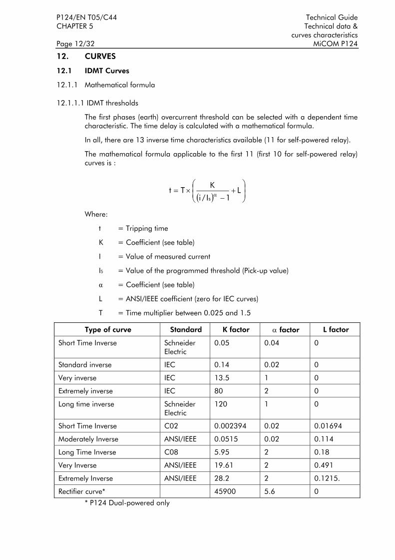
P124/EN T05/C44 Technical Guide CHAPTER 5 Technical data & curves characteristics Page 12/32 MiCOM P124
12. CURVES
12.1 IDMT Curves
12.1.1 Mathematical formula
12.1.1.1 IDMT thresholds
The first phases (earth) overcurrent threshold can be selected with a dependent time characteristic. The time delay is calculated with a mathematical formula.
In all, there are 13 inverse time characteristics available (11 for self-powered relay).
The mathematical formula applicable to the first 11 (first 10 for self-powered relay) curves is :
( ) ⎟⎟⎠
⎞⎜⎜⎝
⎛+
−×=
αL
1I/i
KTt
s
Where:
t = Tripping time
K = Coefficient (see table)
I = Value of measured current
IS = Value of the programmed threshold (Pick-up value)
α = Coefficient (see table)
L = ANSI/IEEE coefficient (zero for IEC curves)
T = Time multiplier between 0.025 and 1.5
Type of curve Standard K factor α factor L factor
Short Time Inverse Schneider Electric
0.05 0.04 0
Standard inverse IEC 0.14 0.02 0
Very inverse IEC 13.5 1 0
Extremely inverse IEC 80 2 0
Long time inverse Schneider Electric
120 1 0
Short Time Inverse C02 0.002394 0.02 0.01694
Moderately Inverse ANSI/IEEE 0.0515 0.02 0.114
Long Time Inverse C08 5.95 2 0.18
Very Inverse ANSI/IEEE 19.61 2 0.491
Extremely Inverse ANSI/IEEE 28.2 2 0.1215.
Rectifier curve* 45900 5.6 0
* P124 Dual-powered only

Technical Guide P124/EN T05/C44 Technical data and CHAPTER 5 curves characteristics MiCOM P124 Page 13/32
The RI curve (electromechanical) is given by the following formula:
( )⎟⎟⎠
⎞⎜⎜⎝
⎛−
×=sI/I/236.0339.0
1Kt
With K adjustable from 0.10 to 10 in steps of 0.05
This equation is valid for 1.1<= (I/IS)<= 20
Although the curves tend towards infinite when the current approaches Is, the minimum guaranteed value of the operating current for all the curves with the inverse time characteristic is 1.1Is (with a tolerance of ± 0,05Is), except rectifier Protection curve for which the minimum value is 1.6 Is ±0.05 Is.
LABORELEC CURVES (P124 Dual-powered only):
The first and second earth threshold can be selected with dedicated Laborelec curves.
There are 3 curves available with the following formula :
bat += I
where : t = tripping time a and b = coefficient (see table) I = Primary residual current (between 1 and 40A)
Type of curve a b
LABORELEC 1 – 0.0897 4.0897
LABORELEC 2 – 0.0897 4.5897
LABORELEC 3 – 0.0897 5.0897
In order to be compliant with the Laborelec specifications the relay must be used with :
− An earth current range 0.01 Ion to 8 Ion
− A rated current wiring 1A
− A core balanced CT with a ratio 20/1.
For a complete operating of the curve, the relay MiCOM P124 must be set to 0.05Ion (secondary residual current).
12.1.1.2 Reset timer
The first phase overcurrent threshold [I>/tI>] ([Ie>/tIe>] for the earth) has a reset time. The fixed period for this determines the minimum time during the current need to remain lower than 95% of the phase (earth) threshold before the time delay associated with the phase (earth) overcurrent threshold resets.
NOTE : There is an exception to this rule when the protection triggers. In fact, in this situation, the time delays tI>/tIe> are immediately reinitialised.

P124/EN T05/C44 Technical Guide CHAPTER 5 Technical data & curves characteristics Page 14/32 MiCOM P124
The value of the Reset Timer depends on the type of the timer associated to the pick-up first phase (Earth) threshold.
Type of timer associated to the first & second phase (earth) threshold
Reset Timer
DMT 0 ms LABORELEC *, Rectifier, IDMT IEC or RI Settable from 40 ms to 100s
IDMT IEEE or CO
Settable from 40 ms to 100s or
Inverse Time (Choice of 5 IEEE curves)
* earth threshold only
Reset timer settable:
The first phase and earth overcurrent stages in the P124 relays are provided with a timer hold facility "t Reset", which may be set to a definite time value or to an inverse time characteristic (IEEE/ANSI curves only). This may be useful in certain applications, for example when grading with upstream electromechanical overcurrent relays which have inherent reset time delays.
Another possible situation where the timer hold facility may be used to reduce fault clearance times is where intermittent faults occur. An example of this may occur in a plastic insulated cable . In this application it is possible that the fault energy melts and reseals the cable insulation, thereby extinguishing the fault. This process repeats to give a succession of fault current pulses, each of increasing duration with reducing intervals between the pulses, until the fault becomes permanent.
When the reset time of the overcurrent relay is minimum the relay will be repeatedly reset and not be able to trip until the fault becomes permanent. By using the Timer Hold facility the relay will integrate the fault current pulses, thereby reducing fault clearance time.
The reset timer "t Reset" facility for the MiCOM P124 can be found in the following menu :
− If the first phase (earth) threshold is selected with an IDMT IEC, Rectifier, Laborelec or RI curve, the reset timer "t Reset" with DMT characteristic is settable in the menu :
− Protection /[50/51] Phase OC/t Reset for the phase
− Protection /[50N/51N] E/Gnd/t Reset for the earth.
− If the first phase (earth) threshold is selected with an IDMT IEEE or CO curve, the reset timer "t Reset" with a DMTor IDMT characteristic is settable in the menu :
− Protection /[50/51] Phase OC/Type Tempo Reset for the phase
− Protection /[50N/51N] E/Gnd/Type Tempo Reset for the earth.
Reset Time "t Reset" with an IDMT characteristic :
The mathematical formula applicable to the five curves is :
( ) ⎟⎟⎠
⎞⎜⎜⎝
⎛
−×= α
sII1K
Tt

Technical Guide P124/EN T05/C44 Technical data and CHAPTER 5 curves characteristics MiCOM P124 Page 15/32
Where :
t = Reset time
K = Coefficient (see table)
I = Value of the measured current
IS = Value of the programmed threshold (pick-up value)
α = Coefficient (see table)
T = Reset Time Multiplier (Rtms) between 0.025 and 3.2
Type of curves Standard K factor α factor Short time inverse C02 0.323 2 Moderately Inverse ANSI/IEEE 4.85 2 Long time Inverse C08 5.95 2 Very inverse ANSI/IEEE 21.6 2 Extremely inverse ANSI/IEEE 29.1 2

P124/EN T05/C44 Technical Guide CHAPTER 5 Technical data & curves characteristics Page 16/32 MiCOM P124 12.1.2 IEC CURVES.
IEC & Schneider Electric Curves
(TMS=0,025)
0,001
0,01
0,1
1
10
1 10 100
MULTIPLES OF PICK UP SETTING
Short time inverse (Schneider Electric)Standard Inverse
Very InverseExtremely Inverse
Long Time Inverse (Schneider Electric)
TIM
E IN
SE
CO
ND
S

Technical Guide P124/EN T05/C44 Technical data and CHAPTER 5 curves characteristics MiCOM P124 Page 17/32
Short Time Inverse (Schneider Electric)
0,001
0,01
0,1
1
10
1 10 100
MULTIPLES OF PICK UP SETTING
TMS=0.025 TMS=0.2 TMS=0.5 TMS=1 TMS=1.25
B
B :
C
C :
D
D :
E
E :
A
A :
TIM
E IN
SE
CO
ND
S

P124/EN T05/C44 Technical Guide CHAPTER 5 Technical data & curves characteristics Page 18/32 MiCOM P124
STANDARD INVERSE (IEC)
MULTIPLES OF PICK UP SETTING
TIM
EIN
SEC
ON
DS

Technical Guide P124/EN T05/C44 Technical data and CHAPTER 5 curves characteristics MiCOM P124 Page 19/32
VERY INVERSE (IEC)
MULTIPLES OF PICK UP SETTING
TIM
EIN
SEC
ON
DS

P124/EN T05/C44 Technical Guide CHAPTER 5 Technical data & curves characteristics Page 20/32 MiCOM P124
EXTREMEMELY INVERSE (IEC)
MULTIPLES OF PICK UP SETTING
TIM
EIN
SEC
ON
DS

Technical Guide P124/EN T05/C44 Technical data and CHAPTER 5 curves characteristics MiCOM P124 Page 21/32
0,1
1
100
1000
10000
1 10 100
E : TMS=0.025 D : TMS=0.2 C : TMS=0.5 B : TMS=1 A : TMS=1.25
LONG TIME INVERSE (Schneider Electric)
AB
C
D
E
TIM
E IN
SE
CO
ND
S
MULTIPLES OF PICK UP SETTING

P124/EN T05/C44 Technical Guide CHAPTER 5 Technical data & curves characteristics Page 22/32 MiCOM P124 12.1.3 RI curves.
RI CURVES
MULTIPLES OF PICK UP SETTING
TIM
EIN
SEC
ON
DS

Technical Guide P124/EN T05/C44 Technical data and CHAPTER 5 curves characteristics MiCOM P124 Page 23/32 12.1.4 IEEE/ANSI Curves.
ANSI/IEEE & CO curves(TMS/RTMS = 0.025)
MULTIPLES OF PICK UP SETTING
Short Time Inverse (CO2)
Long Time Inverse (CO8)
Extremely Inverse
Moderately Inverse
Very Inverse
TIM
EIN
SEC
ON
DS

P124/EN T05/C44 Technical Guide CHAPTER 5 Technical data & curves characteristics Page 24/32 MiCOM P124
SHORT TIME INVERSE (CO2)
MULTIPLES OF PICK UP SETTING
TIM
EIN
SEC
ON
DS

Technical Guide P124/EN T05/C44 Technical data and CHAPTER 5 curves characteristics MiCOM P124 Page 25/32
MODERATELY INVERSE (ANSI/IEEE)
MULTIPLES OF PICK UP SETTING
TIM
EIN
SEC
ON
DS

P124/EN T05/C44 Technical Guide CHAPTER 5 Technical data & curves characteristics Page 26/32 MiCOM P124
LONG TIME INVERSE (CO8)
MULTIPLES OF PICK UP SETTING
TIM
EIN
SEC
ON
DS

Technical Guide P124/EN T05/C44 Technical data and CHAPTER 5 curves characteristics MiCOM P124 Page 27/32
VERY INVERSE (ANSI/IEEE)
MULTIPLES OF PICK UP SETTING
tim
ein
seco
nd
s

P124/EN T05/C44 Technical Guide CHAPTER 5 Technical data & curves characteristics Page 28/32 MiCOM P124
EXTREMELY INVERSE (ANSI/IEEE)
MULTIPLES OF PICK UP SETTING
TIM
EIN
SEC
ON
DS

Technical Guide P124/EN T05/C44 Technical data and CHAPTER 5 curves characteristics MiCOM P124 Page 29/32 12.1.5 Rectifier protection curve
TRIPPING CURVE FUNCTION OF THE PREFAULT LOAD
(k=1.1 & T e=10mn)
MULTIPLES OF THERMAL THRESHOLD SETTING I >
A : no prefault load, thermal state = 0%
B : Thermal state = 30%
C : Thermal state = 50%
D : Thermal state = 70%
E : Thermal state = 90%
TIM
EIN
SEC
ON
DS

P124/EN T05/C44 Technical Guide CHAPTER 5 Technical data & curves characteristics Page 30/32 MiCOM P124 12.1.6 LABORELEC CURVE
Time (sec)
Prim
ary
zero
seq
uenc
e cu
rren
t (A
)
5
1.5
1.0
0.5
1
123
12345
1020
3040
50

Technical Guide P124/EN T05/C44 Technical data and CHAPTER 5 curves characteristics MiCOM P124 Page 31/32 12.2 Thermal overload curves
12.2.1 Mathematical formula
The thermal time characteristic is given by:
exp(-t/τ) = (I2 - (k.IFLC)2 ) / (I2 - IP2)
Where: t = Time to trip, following application of the overload current, I;
τ = Heating and cooling time constant of the protected plant;
I = Largest phase current (RMS value);
IFLC = Full load current rating (relay setting 'Thermal Trip');
k = 1.05 constant, allows continuous operation up to < 1.05 IFLC.
IP = Steady state pre-loading before application of the overload.
The time to trip varies depending on the load current carried before application of the overload, i.e. whether the overload was applied from "hot" or "cold".
Mathematical formula applicable to the MiCOM Relays :
The calculation of the Time to Trip is given by :
⎟⎟⎠
⎞⎜⎜⎝
⎛
θ−θ−
=²trip²K
²²KIn TeTtrip
With :
Ttrip = Time to trip (in seconds)
Te = Thermal time constant of the protected element (in seconds)
K = Thermal overload equal to Ieq/k Iθ>
Ieq = Equivalent current corresponding to the RMS value of the largest phase current.
Iθ> = Full load current rating given by the national standard or by the supplier.
k = Factor associated to the thermal state formula.
θ2 = Initial thermal state. If the initial thermal state = 30% then θ2
= 0.3
θtrip2 = Trip thermal state. If the trip thermal state is set at 100%, then θ trip2
= 1
The calculation of the thermal state is given by the following formula :
θι+1 =(Ieq/ k Iθ>)2 [1- exp(-t/Te)] + θι exp(-t/Te)
θ being calculated every 100ms.
Typical alarm setting : 70 % of t he thermal capacity of the protected element.

P124/EN T05/C44 Technical Guide CHAPTER 5 Technical data & curves characteristics Page 32/32 MiCOM P124 12.2.2 Tripping curve

Technical Guide P124/EN T06/B44 MiCOM P124
CHAPTER 6 Applications Guide


Technical Guide P124/EN T06/B44 Applications Guide CHAPTER 6 MiCOM P124 Page 1/22
CONTENT
1. INTRODUCTION 3
2. RECAP OF THE CURRENT TRANSFORMER CHARACTERISTICS 4
2.1 Characterisation of a current transformer 4
2.2 Equivalent diagram of a current transformer 5
2.2.1 How to calculate the rated output burden in VA of a CT from its characteristic magnitudes (Vk , Rct ) 6
2.2.2 Definition equivalence for common CT 6
2.2.3 How to calculate the knee-point voltage Vk of a CT defined in class P 6
3. REQUIREMENTS FOR CTS TO OPERATE WITH A MiCOM P124 7
3.1 Consumption of MiCOM P124 relays 7
3.1.1 MiCOM P124, rated current 1A 8
3.1.2 MiCOM P124, rated current 5A 9
3.2 Is the MiCOM P124 adapted to a given current transformer? 10
3.2.1 P124 connected to a type AEG IED 24 with a ratio of 1/197 10
3.2.2 P124 CT connected to a type AEG IED 24 with a ratio of 1/150 11
3.3 Recommendations for selecting the CT 11
4. POSSIBLE CONNECTIONS OF THE CTS AT THE P124 INPUT 12
4.1 Connection to 3 phase CTs + core balanced CT 12
4.1.1 Core balanced CT connected to the self-powered earth current input (terminals 55-56) 12
4.1.2 Core balanced CT connected to the measurement earth current input (terminals 47- 48) 12
4.2 The earth current input is connected to the summation of the 3 phase CTs 12
4.3 Connection to 2 phases CTs + core balanced CT 12
5. DESCRIPTION AND SETTING GUIDE OF THE AUTORECLOSE FUNCTION (P124 DUAL-POWERED) 13
5.1 Introduction 13
5.2 Description of the function 15
5.2.1 Autorecloser activation 15
5.2.2 Autoreclose menu 15
5.2.3 Logic Functions 16
5.2.3.1 Logic Inputs 16 5.2.3.2 External CB fail 16

P124/EN T06/B44 Technical Guide CHAPTER 6 Applications Guide Page 2/22 MiCOM P124
5.2.3.3 External starting orders 16 5.2.3.4 External blocking order 16 5.2.3.5 Autoreclose Logic Outputs 17 5.2.3.6 Autoreclose in progress 17 5.2.3.7 Final trip 17 5.2.4 Autoreclose logic operating sequence 17
5.2.5 Autoreclose Inhibit Following Manual Close 18
5.2.6 Recloser lockout 18
5.2.7 Setting group change lockout 18
5.3 Setting Guidelines 18
5.3.1 Number Of Shots 18
5.3.2 Dead Timer Setting 19
5.3.2.1 Load 19 5.3.2.2 Circuit Breaker 19 5.3.2.3 Fault De-ionising Time 20 5.3.2.4 Protection Reset 20 5.3.3 Reclaim Timer Setting 20

Technical Guide P124/EN T06/B44 Applications Guide CHAPTER 6 MiCOM P124 Page 3/22
1. INTRODUCTION
The P124 Self and Dual-Powered overcurrent relays in the MICOM range have been designed to test, protect and monitor both industrial installations and public power distribution networks and substations, without having to resort to an external auxiliary power supply. They can also be used as backup for HV protections of power transmission networks.
These two non-directional overcurrent protection models offer functions of protection and automation that are common with the MiCOM P122 and P123 models. For instance, for applications of MiCOM relays concerning these functions, the user should refer to document P124/EN T05/A44.
The protection relays self-powered by the fault current offer the specific feature of non-conventional current inputs. Accordingly, special attention will be given to the choice of the current transformers supplying these relays.
The following chapters describe our recommendations for choosing the current transformers associated to the MiCOM P124 relays.
The MiCOM P124 protection relays combined with the wiring represent a load for the current transformers. Consequently, the dimensions of the current transformers must be correctly calculated in order to comply with:
• the electrical installation diagram,
• the electrical data such as the nominal current, short-circuit current, ,

P124/EN T06/B44 Technical Guide CHAPTER 6 Applications Guide Page 4/22 MiCOM P124
2. RECAP OF THE CURRENT TRANSFORMER CHARACTERISTICS
2.1 Characterisation of a current transformer
A CT for protection relays is characterised on the basis of:
• Its rated output burden expressed in VA, its relevant accuracy class (5P or 10P) and the accuracy limit current (5In, 10In, 15In, 20In). The accuracy limit factor (K) being the ratio between the precision limit current and the nominal current rating.
• Naturally, the transformation ratio of the CT is to be added to this. This ratio is the ratio of the primary current to the secondary current I1/I2. The secondary current rating is generally 1 A or 5 A.
• Other characteristics such as the insulating voltage or the thermal behaviour are also taken into account.
Standard BS 3938 proposes a specification identical to that of IEC 185 for the class P transformers. The CT is characterised in accordance with a second class known as the X class (Cx) which, in addition to the calculation ratio, requires a knee-point voltage Vk and an internal resistance Rct .
The following magnitudes are associated to the magnetization curve of a CT:
• The knee-point voltage Vk, which is determined by the point of the curve V=f (Im ) beyond which an increase of 10% in the voltage V results in an increase of 50% in the magnetizing current.
• The voltage related to the precision limit of the CT.
⇒ For a 5PK CT (accuracy class 5P, accuracy limit factor K):
At the saturation voltage Vs1 we will have an accuracy of 5% on the current
K * In.
⇒ For a 10PK TC (accuracy class 10P, accuracy limit factor K):
At the saturation voltage Vs2 we will have an accuracy of 10% on the current K*In
Knee pointvoltage
FIGURE 1: DEFINITION OF KNEE-POINT OF MAGNETIZATION CURVE.

Technical Guide P124/EN T06/B44 Applications Guide CHAPTER 6 MiCOM P124 Page 5/22
With the materials generally used to manufacture current transformers, we have:
Vk corresponds to 1.4 tesla
Vs1 corresponds to 1.6 tesla
Vs2 correspond à 1.9 tesla
2.2 Equivalent diagram of a current transformer
The equivalent diagram of a CT is indicated below:
• CT ratio: n2/n1
• Lm : magnetization self-induction coil of CT
• Im : magnetizing current
• I1 : primary current
• I2 : secondary current = I1 * n2 /n1
• Is : secondary current passing through the load Rp. :
• Rct : secondary winding resistance of CT (ohms)
FIGURE 2: EQUIVALENT DIAGRAM OF A CURRENT TRANSFORMER
The magnetizing current I m of the transformer depends on the voltage generated at the secondary windings of the transformer.
It is this current that introduces an error signal into the measurement. If the CT was perfect, the magnetizing current would be zero.
→ → → Is= I2 Im

P124/EN T06/B44 Technical Guide CHAPTER 6 Applications Guide Page 6/22 MiCOM P124
2.2.1 How to calculate the rated output burden in VA of a CT from its characteristic magnitudes (Vk , Rct )
The saturation voltage is derived by the following formula: Vs = (Rct + Rp ) Is
The nominal load rating of the CT being Rp = Pn /I n2
We have Vs = (Rct + Pn /In2 ) Is
whence Pn = (Vs /Is - Rct )In2
• For transformer with in a 5P accuracy class: Vs1 / Vk = 1.6/1.4
Thus: Vs1 = 1.6/1.4 * Vk, at Is1 equals K * In
whence Pn = [(1.6/1.4 * Vk )/K* In - Rct ] *In2
• For transformer with a 10P accuracy class: Vs2 / Vk = 1.9/1.4
thus Vs2 = 1.9/1.4 * Vk, at Is2 equals K * In
whence Pn = [(1.9/1.4 * Vk )/K* In - Rct ] *In2
2.2.2 Definition equivalence for common CT
Knowing that the only constants of a CT are its magnetization curve, its resistance Rct and its transformation ratio , it is possible change from a transformer with a power Pn1 in VA of the 5PK1 type to a transformer with a power of Pn2 in VA of the 5PK2 type.
Given known values of Vs1 and Rct:
Vs1 = (Rct +Pn1 /In2 )*K1 * In = (Rct + Pn2 /In2 )*K2 *In
Pi = Rct * In2 (ohmic loss of CT)
(Pi +Pn1) * K1 = (Pi + Pn2 ) * K2
whence K2 = [(Rct * In2 + Pn1 )/ (Rct * In2 + Pn2 )] * K1
2.2.3 How to calculate the knee-point voltage Vk of a CT defined in class P
• For a transformer with accuracy class of 5P : Vs1 / Vk = 1.6/1.4
Pn = [(1.6/1.4 * Vk )/K* In - Rct ] *In2
whence Vk = 1.4/1.6 (Pn / In 2 + Rct) K * In
• For a transformer with a precision class 10P : V s2 / V k = 1.9/1.4
Pn = [(1.9/1.4 * Vk )/K* In - Rct ] *In2
whence Vk = 1.4/1.9 (Pn / In 2 + Rct) K * In.

Technical Guide P124/EN T06/B44 Applications Guide CHAPTER 6 MiCOM P124 Page 7/22
3. REQUIREMENTS FOR CTS TO OPERATE WITH A MiCOM P124
For the conventional case of a resistive load, the voltage at the secondary winding of the transformer is proportional to the primary current, so the error remains constant.
In the case of a MiCOM P124 type self-powered protection relay, this no longer applies, since the voltage at the input of the protection circuit is in a non-proportional ratio to the input current.
The best solution to check whether the MiCOM P124 relay is adapted to a given CT is to have available the magnetization curve and the internal resistance of the CT in question.
To guarantee good precision at low currents, the magnetizing current of the CT must be low. In other words, the input voltage of the relay must be sufficiently low compared with the knee-point voltage Vk of the CT.
The following paragraphs show the ac burden of the P124 MiCOM relay and, knowing the magnetisation curve of a CT, one can then determine the precision of the system as a whole, for the entire current range: PROTECTION P124 + associated CT.
3.1 Consumption of MiCOM P124 relays
The MiCOM P124 self and dual-powered models (with identical ac burden at their current inputs) have a minimum self-supply starting current of 0.2 In. This minimum level of current is needed on at least one phase to enable the MiCOM relay to be correctly self-powered to ensure the full capability of its protection functions:
CAUTION: THE FOLLOWING ARE THE THERMAL CHARACTERISTICS
• 3 In continuous rating
• 40 In during 100 s
• 100 In during 1 s

P124/EN T06/B44 Technical Guide CHAPTER 6 Applications Guide Page 8/22 MiCOM P124
3.1.1 MiCOM P124, rated current 1A
The figure below indicates the voltage (average value of signal for 10 ms) on each phase or on earth current input (across terminals 55 and 56), depending on the current injected.
P124
ver
sion
In=
1A
05
1015
0.00
10.0
020
.00
30.0
040
.00
50.0
060
.00
Cur
rent
In (A
)In
Average voltage (V)
FIGURE 3: CURRENT INPUT BURDEN, RATED CURRENT 1A

Technical Guide P124/EN T06/B44 Applications Guide CHAPTER 6 MiCOM P124 Page 9/22
3.1.2 MiCOM P124, rated current 5A
The figure below indicates the voltage (average value of signal for 10 ms) on each phase or on earth current input (across terminals 55 and 56), depending on the current injected.
P124
ver
sion
In=
5A
012 0.00
10.0
020
.00
30.0
040
.00
50.0
060
.00
Cur
rent
In (A
)In
Average voltage (V)
FIGURE 4: CURRENT INPUT BURDEN, RATED CURRENT 5A

P124/EN T06/B44 Technical Guide CHAPTER 6 Applications Guide Page 10/22 MiCOM P124
3.2 Is the MiCOM P124 adapted to a given current transformer?
The purpose of this chapter is to show the adequacy of the MiCOM P124 relay to a given CT.
We propose to take as an example the AEG IED 24 reference multi-secondary windings CT.
3.2.1 P124 connected to a type AEG IED 24 with a ratio of 1/197
The characteristics indicated by the maker of the CT are as follows:
Rated current In = 1A, Class X (Cx), Vk>38.0 V, Rct <0.443 ohms
Given the burden of a phase input for a given current (see paragraphs 3.1.1 and 3.1.2). The charts of the maker of the CT indicate the magnetizing current in terms of the voltage and we can then calculate the error caused by the magnetizing current for the following three currents:
MiCOM P124, rated current In = 1A
Current 0.2 In (starting current) In 40 In
Voltage 4.3 V 2.66 V 11.8 V
Magnetizing current
0,006 A 0.006 A 0.01 A
Error 3 % 0.6 % 0.025 %
The errors calculated reveal a maximum error of 3 % at minimum current, with this error inversely proportional to the current.
Referring to chapter 2.2.1, we can derive the corresponding rated output burden in the P class of this transformer expressed in terms of Vk and R ct. as follows:
• The corresponding rated output burden of this CT in class 5 is:
Pn = [(1.6/1.4 * Vk )/10* In - Rct ] *In2
with In = 1 A and an accuracy limit factor of 10
Pn = 3.89 VA 5P10
• The corresponding rated output burden of this CT in class 10 is:
Pn = [(1.9/1.4 * Vk )/10* In - Rct ] *In2
with In = 1 A and an accuracy limit factor of 10.
Pn = 4.71 VA 10P10
Test were conducted on the MiCOM P124 with this CT and confirmed the satisfactory operation of the combination CT + P124.
NOTE: in this example, the relay was connected along side the CT; in this way, the influence of the wiring was negligible.

Technical Guide P124/EN T06/B44 Applications Guide CHAPTER 6 MiCOM P124 Page 11/22
3.2.2 P124 CT connected to a type AEG IED 24 with a ratio of 1/150
The characteristics indicated by the maker of the CT are:
Rated current In = 1A, Class X (Cx), Vk>28.6 V, Rct <0.393 ohms
Given the burden of a phase input for a given current (see paragraphs 3.1.1 and 3.1.2). Since the charts of the maker of the CT indicate a magnetizing current against voltage, we can calculate the error caused by the magnetizing current for the following three currents :
MiCOM P124, rated current In = 1A
Current 0.2 In (starting current)
In 40 In
Voltage 4.3 V 2.66 V 11.8 V
Magnetising current 0.01 A 0.01 A 0.017 A
Error 5 % 1 % 0.042 %
The errors calculated reveal a maximum error of 5 % at minimum current, with this error inversely proportional to the current.
Referring to chapter 2.2.1, we can derive a corresponding rated output burden in class P of this transformer expressed in terms of Vk and R ct as folles :
• The corresponding rated output burden of this CT in class 5 is:
Pn = [(1.6/1.4 * Vk )/10* In - Rct ] *In2
with In = 1 A and an accuracy limit factor of 10
Pn = 2.87 VA 5P10
• The corresponding rated output burden of this CT in class 10 is:
Pn = [(1.9/1.4 * Vk )/10* In - Rct ] *In2
with In = 1 A and an accuracy limit factor of 10.
Pn = 3.48 VA 10P10
Tests were conducted on the MiCOM P124 with this CT and confirmed the satisfactory operation of the combination CT + P124.
NOTE: in this example, the relay was connected alongside the CT, so the influence of the wiring was negligible.
3.3 Recommendations for selecting the CT
Assuming that the CT does not supply any circuits other than the MiCOM P124, in practice, we can recommend CTs of the following types:
5VA 5P10 or 5VA 10P10
secondary 1A or 5A.

P124/EN T06/B44 Technical Guide CHAPTER 6 Applications Guide Page 12/22 MiCOM P124
4. POSSIBLE CONNECTIONS OF THE CTS AT THE P124 INPUT
For the diagrams, consult those indicated in appendix 1 of the technical guide.
4.1 Connection to 3 phase CTs + core balanced CT
4.1.1 Core balanced CT connected to the self-powered earth current input (terminals 55-56)
Advantage:
This connection is advantageous when the transformation ratio of the core CT is less than that of the phase CTs (greater sensitivity demand on the earth range). This enables the fault at the earth current input of the protection to be perceived even if this fault is not of sufficient level (0.2 In) to supply the protection via the phase currents, in which case the fault could self-power the protection through the earth current input.
Disadvantage:
The core CT must be appropriately dimensioned, that is it must have few turns, to ensure good sensitivity whilst nonetheless being capable of providing the burden in VA needed for the protection.
4.1.2 Core balanced CT connected to the measurement earth current input (terminals 47- 48)
Advantage:
In this case, there is no need for the core CT to supply the MiCOM P124 through the earth current input, so the core has no need to be overdimensioned in terms of power.
Disadvantage:
No self-supply of the MiCOM P124 by the earth current input and hence the need for a minimum current at the phases (0.2 In).
4.2 The earth current input is connected to the summation of the 3 phase CTs
Advantage:
In this case, the earth current is detected by summing the 3 phase CTs, so there is no need to use a core CT. The summing operation is conducted at terminals 47-48 of the earth current input, so there is no need for the CTs to supply the relay via the earth current input.
Disadvantage:
Less accuracy than core CT connection.
4.3 Connection to 2 phases CTs + core balanced CT
Advantage:
Only 2 CTs are used, resulting in saving one phase CT. The third phase is reformed by the wiring.
Disadvantage:
The phase and earth CTs must be suitably overdimensioned. The core CT must be connected to the supply input of the earth current input (terminals 55-56).
We assume that the system is balanced.

Technical Guide P124/EN T06/B44 Applications Guide CHAPTER 6 MiCOM P124 Page 13/22
5. DESCRIPTION AND SETTING GUIDE OF THE AUTORECLOSE FUNCTION (P124 DUAL-POWERED ONLY)
5.1 Introduction
An analysis of faults on any overhead line network has shown that 80-90% are transient in nature.
A transient fault, such as an insulator flash-over, is a self clearing non-damage fault. This type of fault can be cleared by the immediate tripping of one or more circuit breakers to isolate the fault, and does not recur when the line is re-energised. Lightning is the most common cause of transient faults, other possible causes being clashing conductors and wind blown debris. The remaining 10 - 20% of faults are either non-permanent (arcing fault) or permanent.
A non-permanent fault could be caused by a small tree branch falling on the line. Here the cause of the fault would not be removed by the immediate tripping of the circuit, but could be burnt away during a time delayed trip.
Permanent faults could be broken conductors, transformer faults, cable faults or machine faults which must be located and repaired before the supply can be restored.
In the majority of fault incidents, if the faulty line is immediately tripped out, and time is allowed for the fault arc to de-ionise, reclosure of the circuit breakers will result in the line being successfully re-energised. Autoreclose schemes are employed to automatically reclose a switching device a set time after it has been opened due to operation of protection where transient and non-permanent faults are prevalent.
On HV/MV distribution networks, auto-reclosing is applied mainly to radial feeders where system stability problems do not generally arise. The main advantages to be derived from using autoreclose can be summarised as follows:
• Minimises interruptions in supply to the consumer.
• Reduces operating costs - less man hours in repairing fault damage and the possibility of running substations unattended. With autoreclose instantaneous protection can be used which means shorter fault durations which gives rise to less fault damage and fewer permanent faults.
As 80% of overhead line faults are transient, elimination of loss of supply from such faults, by the introduction of autoreclosing gives obvious benefits. Furthermore, autoreclosing may allow a particular substation to operate unattended. In the case of unattended substations, the number of visits by personnel to reclose a circuit breaker manually after a fault can be substantially reduced, an important consideration for substations in remote areas.
Autoreclosing gives an important benefit on circuits using time graded protection, in that it allows the use of instantaneous protection to give a high speed first trip. With fast tripping, the duration of the power arc resulting from an overhead line fault is reduced to a minimum, thus lessening the chance of damage to the line, which might otherwise cause a transient fault to develop into a permanent fault.
Using short time delay protection also prevents blowing of fuses and reduces circuit breaker maintenance by eliminating pre-arc heating when clearing transient faults.

P124/EN T06/B44 Technical Guide CHAPTER 6 Applications Guide Page 14/22 MiCOM P124
Figure 5 shows an example of 4 autoreclose cycles to the final trip :
td1, td2, td3, td4 = dead time 1, 2, 3 and 4 timers
tr = Reclaim type
O = CB open
C = CB closed.
FIGURE 5: TYPICAL AUTORECLOSE CYCLES
It should be noted that when short time delay protection is used with autoreclosing, the scheme is normally arranged to block the instantaneous protection after the first trip. Therefore, if the fault persists after reclosure, the time graded protection will give discriminative tripping with fuses or other protection devices, resulting in the isolation of the faulted section. However, for certain applications, where the majority of the faults are likely to be transient, it is not uncommon to allow more than one instantaneous trip before the instantaneous protection is blocked.
Some schemes allow a number of reclosures and time graded trips after the first instantaneous trip, which may result in the burning out and clearance of non-permanent faults. Such a scheme may also be used to allow fuses to operate in teed feeders where the fault current is low.
When considering feeders which are partly overhead line and partly underground cable, any decision to install autoreclosing would be influenced by any data known on the frequency of transient faults. When a significant proportion of the faults are permanent, the advantages of autoreclosing are small, particularly since reclosing on to a faulty cable is likely to aggravate the damage.

Technical Guide P124/EN T06/B44 Applications Guide CHAPTER 6 MiCOM P124 Page 15/22
5.2 Description of the function
5.2.1 Autorecloser activation
The autoreclose function of the MiCOM P124 Dual-powered is available only if the following conditions are verified :
• The auxiliary contact of the CB status 52a must be connected to the relay See AUTOMAT. CTRL/Inputs menu
• The trip output relay RL1 must not be latched to the earth and/or phase protection function See AUTOMAT. CTRL/Latch functions menu
CAUTION : IF THE AUXILIARY SUPPLY IS LOST DURING AN AUTORECLOSE CYCLE, THE AUTORECLOSE FUNCTION IS TOTALLY DISABLED.
5.2.2 Autoreclose menu
The following table shows the relay settings for the autoreclose function, including the available setting ranges. The same settings are available in the PROTECTION 2 Menu.
MENU TEXT SETTING RANGE STEP SIZE PROTECTION G1 MIN MAX Autoreclose ? NO YES Ext CB Fail ? NO YES Ext CB Fail Time 10 ms 600 s 10 ms Ext Block ? NO YES Dead Time tD1 10 ms 300 000 ms 10 ms Dead Time tD2 10 ms 300 000 ms 10 ms Dead Time tD3 10 ms 600 000 ms 10 ms Dead Time tD4 10 ms 600 000 ms 10 ms Reclaim Time tR 20 ms 600 000 ms 10 ms Inhib Time tI 20 ms 600 000 ms 10 ms Phase Cycles 0 4 1 E/Gnd Cycles 0 4 1 CYCLES tI>
4321 1201
CYCLES tI>>
4321 1211
CYCLES tI>>>
4321 1110
CYCLES tIe>
4321 0111
CYCLES tIe>>
4321 1121
CYCLES tIe>>>
4321 1111
CYCLES tAux1
4321 1112
CYCLES tAux2
4321 0101

P124/EN T06/B44 Technical Guide CHAPTER 6 Applications Guide Page 16/22 MiCOM P124
Example of setting :
CYCLES tI>
4321 1201
4321 are the cycles 1 to 4 associated to the trip on tI> pick up 1201 are the actions following the tI> time out : 0 = no action on autorecloser : definitive trip 1 = trip on tI> pick up, followed by reclosing cycle 2 = no trip on tI> pick up : and this whatever the setting in AUTOMAT. CRTL/Trip commands/Trip tI> menu.
In addition to these settings, function links in the PROTECTION G1/Phase OC or PROTECTION/E/Gnd menus are also required to fully integrate the autoreclose logic in the MiCOM P124 relay. Refer to the User Guide of the Technical Guide.
5.2.3 Logic Functions
5.2.3.1 Logic Inputs
The autoreclose function has four inputs affecting the logic, which are configured to any of the opto-isolated inputs on the relay via the AUTOMAT. CTRL/Inputs menu. External inputs may be used to influence the autorecloser scheme. The function of these inputs are described below.
5.2.3.2 External CB fail
The majority of circuit breakers are only capable of providing one trip-close-trip cycle. Following this, it is necessary to establish if there is sufficient energy to reclose the CB. The input assigned to CB FLT function is used to ensure that there is sufficient energy available to close and trip the CB before initiating a CB close command. If on completion of the dead time, sufficient energy is not available by checking the CB FLT input for a time given by the tCFE, a lockout occur and the CB remains open.
This function is disabled by not allocating the function in the PROTECTION G1/Autoreclose menu (function Ext CB Fail to NO).
5.2.3.3 External starting orders
Two separate and programmable inputs (AUTOMAT.CTRL/INPUTS/Aux1(2) menu) may be used to initiate the autorecloser function from an external device (such as an existing overcurrent relay). These logic inputs may be used independently and also in parallel with the MiCOM P124 Overcurrent settings.
These external orders can be disabled independently by not allocating the functions in the PROTECTION G1/Autoreclose/CYCLES tAux1 menu and PROTECTION G1/Autoreclose/CYCLES tAux2 menu.
5.2.3.4 External blocking order
The input assigned to the Block-79 function (programmable in the AUTOMAT.CTRL/INPUTS menu) may block the autoreclose function and cause a lock-out if the autorecloser function is in progress. This input can be used when protection operation without autorecloser function is required.
A typical example is on a transformer feeder, where autoreclosing may be initiated from the feeder protection but need to be blocked from the transformer protection side.

Technical Guide P124/EN T06/B44 Applications Guide CHAPTER 6 MiCOM P124 Page 17/22
These external order can be disabled by not allocating the function in the PROTECTION/Autoreclose/Ext Block menu.
5.2.3.5 Autoreclose Logic Outputs
The following output signals can be assigned to relay contact or to LEDs to provide information about the status of the auto Reclose cycle. These are described below, identified by their namings.
5.2.3.6 Autoreclose in progress
The "Autoreclose in progress" signal is present during the complete reclose cycles from protection initiation to the end of the reclaim time or lockout.
The "Autoreclose in progress" information is allocated to a LED in the CONFIGURATION/Led/Recloser Run menu.
The "Autoreclose in progress" information is allocated to the output relays in the AUTOMAT.CTRL/Output Relays/79 Run menu.
5.2.3.7 Final trip
The "Final trip" signal indicates that an autoreclose cycle has been completed. A autoreclose signal is given after the CB has tripped from the protection and reclosed whereupon the fault has not been cleared. The "Final trip" signal is reset at the next CB manual closing order after the inhibit time (tI).
The inhibit time (tI) is settable in the PROTECTION G1/Autoreclose/Inhib Time menu.
The "Final trip" signal is allocated to the output relays in the AUTOMAT.Ctrl/Output Relays/79 Trip menu.
The "Final trip" signal is allocated to a LED in the CONFIGURATION/Led/Recloser Blocked menu.
5.2.4 Autoreclose logic operating sequence
The autoreclose function provides multi-shot three phase autoreclose control. It can be adjusted to perform a single shot, two shot, three shot or four shot cycle, selectable via Phase Cycles numbers and E/Gnd Cycles numbers. Dead times for all shots (reclose attempts) are independently adjustable.
The number of shots is directly related to the type of faults likely to occur on the system and the voltage level of the system. Generally, on medium voltage networks where the percentage of transient and non-permanent faults is likely to be high, a multi-shot autoreclose device will increase the possibility of the distribution line being successfully re-energised following reclosure of the circuit breaker.
An autoreclose cycle can be internally initiated by operation of a protection element (phase or earth), provided the circuit breaker is closed until the instant of protection operation. The dead time (Dead Time tD1, Dead Time tD2, Dead Time tD3, Dead Time tD4) starts when the CB has tripped (when the 52a input disappears).
At the end of the relevant dead time, a CB close signal is given, provided system conditions are suitable. The system conditions to be met for closing are that the circuit breaker closing spring, or other energy source, is fully charged indicated from the CB FLT input. The CB close signal is cut-off when the circuit breaker closes.
When the CB has closed the reclaim time (Reclaim Time tR) starts.
If the circuit breaker does not trip again, the autoreclose function resets at the end of the reclaim time.

P124/EN T06/B44 Technical Guide CHAPTER 6 Applications Guide Page 18/22 MiCOM P124
If the protection operates during the reclaim time the relay either advances to the next shot in the programmed autoreclose cycle, or, if all programmed reclose attempts have been made, goes to lockout.
The total number of reclosures and for each cycle is shown in the MEASUREMENT menu. This value can be reset to zero with command "C" (Clear) in the MEASUREMENTS/Reclose Stats menu.
5.2.5 Autoreclose Inhibit Following Manual Close
The Inhib Time tI setting can be used to prevent autoreclose being initiated when the CB is manually closed onto a fault. Autoreclose is disabled for the Inhib Time tI following manual CB Closure.
5.2.6 Recloser lockout
If protection operates during the reclaim time, following the final reclose attempt, the relay will lockout and the autoreclose function is disabled until the lockout condition resets.
The lockout condition is reset by a manual closing after the "Inhib Time tI".
Autoreclose lockout can also be caused by a CB FLT input. This CB FLT information can be issued from the CB springs are not charged/Low gas pressure.
Note, lockout can also be caused by :
• CB no open after tBf delay (CB Fail)
• CB Operating Time over the threshold set.
5.2.7 Setting group change lockout
Change of setting groups is only assumed by the MiCOM P124 relays if no protection functions (except thermal overload function) or automation functions is running. During the whole autorecloser cycles, if any setting group change order is received, this order is stored in memory, and will be executed after the last timer of the autorecloser cycle.
5.3 Setting Guidelines
5.3.1 Number Of Shots
There are no clear-cut rules for defining the number of shots for a particular application. Generally medium voltage systems utilise only two or three shot autoreclose schemes. However, in certain countries, for specific applications, four shots is not uncommon. Four shots have the advantage that the final dead time can be set sufficiently long to allow any thunderstorms to pass before reclosing for the final time, this arrangement will prevent unnecessary lockout for consecutive transient faults.
Typically, the first trip, and sometimes the second, will result from short time protection since 80% of faults are transient, the subsequent trips will be time delayed, all with increasing dead times to clear non-permanent faults.
In order to determine the required number of shots the following factors must be taken into account.

Technical Guide P124/EN T06/B44 Applications Guide CHAPTER 6 MiCOM P124 Page 19/22
An important consideration is the ability of the circuit breaker to perform several trip-close operations in quick succession and the effect of these operations on the maintenance period.
If statistical information on a particular system shows a moderate percentage of non-permanent faults which could be burned out, two or more shots are justified. In addition to this, if fused tees are used and the fault level is low, the fusing time may not discriminate with the main IDMT relay and it would then be useful to have several shots. This would warm up the fuse to such an extent that it would eventually blow before the main protection operated.
5.3.2 Dead Timer Setting
The factors which influence the choice of dead timer setting are as follows.
5.3.2.1 Load
Due to the great diversity of load which may exist on a system it may prove very difficult to arrive at an optimum dead time. However, it is possible to address each type of load individually and thereby arrive at a typical dead time. The most common types of load are addressed below.
Synchronous motors are only capable of tolerating extremely short interruptions of supply without loss of synchronism. In practice it is desirable to disconnect the motor from the supply in the event of a fault; the dead time should be sufficient to allow the motor no-volt device to operate. Typically, a minimum dead time of 0.2-0.3 seconds has been suggested to allow this device to operate. Induction motors, on the other hand, can withstand supply interruptions, up to a maximum of 0.5 seconds and re-accelerate successfully. In general dead times of 3-10 seconds are normally satisfactory, but there may be special cases for which additional time is required to permit the resetting of manual controls and safety devices.
Loss of supply to lighting circuits, such as street lighting may be important for safety reasons as intervals of 10 seconds or more may be dangerous for traffic. The main considerations for domestic customers are those of inconvenience.
An important measurement criteria for many power utilities is the number of minutes lost per year to customers which will be reduced on feeders using autoreclose and will also be affected by the dead time settings used.
5.3.2.2 Circuit Breaker
For high speed autoreclose the minimum dead time of the power system will depend on the minimum time delays imposed by the circuit breaker during a tripping and reclosing operation.
Since a circuit breaker is a mechanical device, it will have an inherent contact separation time. This operating time for a modern circuit breaker is usually within the range of 50-100ms, but could be longer with older designs.
After tripping, time must be allowed for the mechanism to reset before applying a closing pulse. This resetting time will vary depending on the circuit breaker, but is typically 0.1 seconds.
Once the circuit breaker has reset, the breaker can begin to close. The time interval between the energisation of the closing mechanism and the making of the contacts is termed the closing time. Owing to the time constant of a solenoid closing mechanism and the inertia of the plunger, a solenoid closing mechanism may take 0.3s. A spring operated breaker, on the other hand, can close in less than 0.2 seconds.

P124/EN T06/B44 Technical Guide CHAPTER 6 Applications Guide Page 20/22 MiCOM P124
Where high speed reclosing is required, for the majority of medium voltage applications, the circuit breaker mechanism itself dictates the minimum dead time. However, the fault de-ionising time may also have to be considered.
High speed autoreclose may be required to maintain stability on a network with two or more power sources. For high speed autoreclose the system disturbance time should be minimised by using fast protection, <50 ms, such as distance or feeder differential protection and fast circuit breakers < 100 ms. Fast fault clearance can reduce the required fault arc de-ionising time.
For stability between two sources a dead time of <300 ms may typically be required. The minimum system dead time only considering the CB is the mechanism reset time plus the CB closing time. Thus, a solenoid mechanism will not be suitable for high speed autoreclose as the closing time is generally too long.
5.3.2.3 Fault De-ionising Time
For high speed autoreclose the fault de-ionising time may be the most important factor when considering the dead time. This is the time required for ionised air to disperse around the fault position so that the insulation level of the air is restored. This can be approximated from:
De-ionising time = (10.5 + ((system voltage in kV)/34.5)) / frequency
For 66 kV = 0.25 s (50Hz)
For 132 kV = 0.29 s (50 Hz)
5.3.2.4 Protection Reset
It is essential that the protection fully resets during the dead time, so that correct time discrimination will be maintained after reclosure on to a fault. For high speed autoreclose instantaneous reset of protection is required.
Typical 11/33kV dead time settings in the UK are as follows;
1st dead time = 5 - 10 seconds
2nd dead time = 30 seconds
3rd dead time = 60 - 100 seconds
4th dead time (uncommon in the UK, however used in South Africa) = 60 - 100 seconds
5.3.3 Reclaim Timer Setting
A number of factors influence the choice of the reclaim timer, such as;
• Supply continuity - Large reclaim times can result in unnecessary lockout for transient faults.
• Fault incidence/Past experience - Small reclaim times may be required where there is a high incidence of lightning strikes to prevent unnecessary lockout for transient faults.
• Spring charging time - For high speed autoreclose the reclaim time may be set longer than the spring charging time to ensure there is sufficient energy in the circuit breaker to perform a trip-close-trip cycle. For delayed autoreclose there is no need as the dead time can be extended by an extra CB healthy check window time if there is insufficient energy in the CB. If there is insufficient energy after the check window time the relay will lockout.

Technical Guide P124/EN T06/B44 Applications Guide CHAPTER 6 MiCOM P124 Page 21/22
• Switchgear Maintenance - Excessive operation resulting from short reclaim times can mean shorter maintenance periods. A minimum reclaim time of >5s may be needed to allow the CB time to recover after a trip and close before it can perform another trip-close-trip cycle. This time will depend on the duty (rating) of the CB.
The reclaim time must be long enough to allow any time delayed protection initiating autoreclose to operate. Failure to do so would result in premature resetting of the autoreclose scheme and re-enabling of instantaneous protection.
If this condition arose, a permanent fault would effectively look like a number of transient faults, resulting in continuous autoreclosing unless additional measures were taken to overcome this such as excessive fault frequency lockout protection.
It is possible to have short reclaim times by blocking the reclaim time from the protection start signals. If short reclaim times are to be used then the switchgear rating may dictate the minimum reclaim time. The advantage of a short reclaim time is that there are less lockouts of the CB, however, there will be more CB operations and so maintenance periods would be reduced.
Sensitive earth fault protection is applied to detect high resistance earth faults and usually has a long time delay, typically 10-15s. This longer time may have to be taken into consideration, if autoreclosing from SEF protection, when deciding on a reclaim time, if the reclaim time is not blocked by an SEF protection start signal. Sensitive earth faults, for example, a broken overhead conductor in contact with dry ground or a wood fence, is rarely transient and may be a danger to the public.
It is therefore common practice to block autoreclose by operation of sensitive earth fault protection and lockout the circuit breaker.
Where motor-wound spring closed circuit breakers are used, the reclaim time must be at least as long as the spring winding time for high speed autoreclose to ensure that the breaker can perform a trip-close-trip cycle.
A typical 11/33kV reclaim time is 3-10 seconds, this prevents unnecessary lockout during thunderstorms. However, times up to 60-180 seconds may be used.

P124/EN T06/B44 Technical Guide CHAPTER 6 Applications Guide Page 22/22 MiCOM P124
BLANK PAGE

Technical guide P124/EN T07/B44 MiCOM P124
CHAPTER 7 Commissioning and Maintenance Guide


Technical Guide P124/EN T07/B44 Commissioning and Maintenance CHAPTER 7 MiCOM P124 Page 1/22
CONTENT
1. REQUIREMENTS PRIOR TO COMMISSIONING 3
2. COMMISSIONING TEST ENVIRONMENT 4
2.1 Important notes 4
2.1.1 Injection test sets 4
2.1.2 Additional commissioning test equipment 4
2.1.3 Communication 4
2.2 Commissioning test sheets 5
3. PRODUCT VERIFICATION TESTS 6
3.1 Allocation of terminals 6
3.2 Electrostatic discharge (ESD) 6
3.3 Visual inspection 6
3.4 Earthing 6
3.5 Current transformers (CT's) 6
3.5.1 Use of a Core CT for earth faults. 6
3.5.1.1 Cable shields and core CT 7
3.5.1.2 Induced current flow through electric cables 7
3.5.1.3 Core CT polarity 8
3.6 Auxiliary supply (Dual-powered model only) 8
3.7 Logic inputs (Dual-powered model only) 9
3.8 Logic outputs (Dual-powered model only) 9
3.9 Logic outputs (Self-powered version ) 10
3.10 RS 485 rear communication (Dual-powered model only) 10
4. COMMISSIONING 11
4.1 Settings 11
4.2 Measurements 11
4.2.1 MiCOM P124 Self-powered 11
4.2.2 MiCOM P124 Dual-powered 11
4.3 Phase overcurrent (I> and I>>) 12
4.3.1 Test wiring diagram 12
4.3.2 MiCOM settings 13
4.3.3 I> threshold with DMT tI> 13
4.3.4 I> threshold with IDMT tI> 14
4.3.5 I>> threshold 16
4.4 Final checks 17

P124/EN T07/B44 Technical Guide CHAPTER 7 Commissioning and Maintenance Page 2/22 MiCOM P124
5. MAINTENANCE 18
5.1 Equipment failure 18
5.1.1 Minor fault (Version Dual-powered only) 18
5.1.2 Major fault 19
5.2 Method of repair 20
5.2.1 Replacing the active part 20
5.2.2 Replacing the complete relay 20
5.2.3 Changing the battery (MiCOM P124 Dual-powered only) 21
5.3 Problem solving 21
5.3.1 Password lost or not accepted 21
5.3.2 Communication (version Dual-powered only) 21
5.3.2.1 Values measured locally and remotely 21
5.3.2.2 MiCOM relay no longer responds 22
5.3.2.3 A remote command is not taken in account 22

Technical Guide P124/EN T07/B44 Commissioning and Maintenance CHAPTER 7 MiCOM P124 Page 3/22
1. REQUIREMENTS PRIOR TO COMMISSIONING
The MiCOM P124 relays are fully numerical in their design, implementing all protection and non-protection functions in software. The MiCOM relays employ a high degree of self-checking and, in the unlikely event of a failure, will give an alarm. As a result of this, the commissioning test do not need to be as extensive as with non- numerical relays (static or electromechanical).
To commission MiCOM relays, it is only necessary to verify that the hardware is functioning correctly and the application-specific software setting have been applied to the MiCOM relay. It is considered unnecessary to test every function of the relay if the settings have been verified by one of the following method :
− Extracting the settings applied to the relay using the setting software MiCOM S1 (preferred method)
− Via the front panel user interface.
Reminder : It is not possible to download a new setting software as long as the programming mode is active.
NOTA : Blank commissioning test and setting records are provided at the APPENDIX 2 of the Technical Guide for completion as required.
WARNING : BEFORE COMMISSIONING THE RELAY, THE SAFETY SECTION OF THE MANUAL MUST BE READ.

P124/EN T07/B44 Technical Guide CHAPTER 7 Commissioning and Maintenance Page 4/22 MiCOM P124
2. COMMISSIONING TEST ENVIRONMENT
2.1 Important notes
All the commissioning tests of the MiCOM P124 relay are carried out by injecting currents to the secondary of the earth and/or phases CTs using appropriate injection test sets provided for this purpose.
2.1.1 Injection test sets
For reasons of convenience (weight, spatial requirement, transportation), a single- phased injection test set is more suitable for commissioning and is able to perform all commissioning tests regarding MiCOM P124 relay.
Thus, the following descriptions indicate how to conduct the commissioning tests with a single-phase injection test set.
Single-phase injection test set
1 current (0 to 50 A), timer (precision 1 ms).
The output power necessary to power the relay is: 2.5 VA
2.1.2 Additional commissioning test equipment
• 1 multimeter (precision 1%),
• 1 connecting terminal to measure the currents exceeding 10 A (precision 2%),
• Test plugs and wires to carry out injections to the CT's secondary (dimension according to the currents injected).
• Battery box MiCOM E1 for the self-powered model (see note) if the injected current is lower than the minimum current specified to power the relay.
• Type K1.3 or equivalent striker.
NOTE : the battery box can also be used for the dual-powered model, when it is not powered by an external auxiliary voltage.
2.1.3 Communication
For all commissioning tests, the records can be made by using the RS 485 communication on the rear connector of the MiCOM P124 (dual-powered only) relays or using the RS232 front port (both self and dual-powered models).
According to each RS 485 communication protocol (MODBUS, Courier, IEC 60870-5-103 or DNP3), use the dedicated Schneider Electric software MiCOM S1.

Technical Guide P124/EN T07/B44 Commissioning and Maintenance CHAPTER 7 MiCOM P124 Page 5/22
2.2 Commissioning test sheets
Commissioning test sheets are available in the APPENDIX 2 of the Technical Guide.
The presentation of the Commissioning test sheets follows the description of the tests of this chapter.
The contents of these Commissioning test sheets enable you to log :
• The name of the relay, station and circuit
• The characteristics of the MiCOM P124 relay
• The various settings
• The results of the protection and automation checks
• The result of the test records after commissioning.

P124/EN T07/B44 Technical Guide CHAPTER 7 Commissioning and Maintenance Page 6/22 MiCOM P124
3. PRODUCT VERIFICATION TESTS
3.1 Allocation of terminals
It is necessary to consult the appropriate wiring diagram provided in the APPENDIX 1 of the Technical Guide whilst observing the various polarities and ground/earth connection.
3.2 Electrostatic discharge (ESD)
Before any handling of the module (active part of the relay), please refer to the recommendations in User guide of this Technical Guide.
3.3 Visual inspection
Carefully examine the relay to see if there has been any possible deterioration following installation.
Check if the external wiring corresponds to the appropriate relay diagram or the assembly diagram. The reference number of the relay diagram is indicated on a label situated under the upper flap of the front panel.
When the relay is withdraw from its case, use a continuity tester to check if the current short-circuits (phases and earth CT's) between the terminals indicated on the wiring diagram are closed.
3.4 Earthing
Check if the earth connection of the case situated above the rear terminal block is used to connect the relay to a local earth bar. With several relays present, make sure that the copper earth bar is properly installed for solidly connecting the earthing terminals of each case.
3.5 Current transformers (CT's)
NEVER OPEN CIRCUIT THE SECONDARY CIRCUIT OF A CURRENT TRANSFORMER SINCE THE HIGH VOLTAGE PRODUCED MAY BE LETHAL AND COULD DAMAGE INSULATION.
3.5.1 Use of a Core CT for earth faults.
If a core CT is used to detect earth faults, prior to any test, the user must check the following points :
1. MV or HV cable screens and core CT,
2. No current flow through the MV or HV cables,
3. Orientation of the core CT (P1-S1, P2-S2).
!

Technical Guide P124/EN T07/B44 Commissioning and Maintenance CHAPTER 7 MiCOM P124 Page 7/22
3.5.1.1 Cable shields and core CT
When mounting a core CT around electric cables, check the connection to the earth of the cable shields. It is vital that the earth cable of the shield moves in the opposite direction through the core CT. This cancel the currents carried by the cable shields through the core CT.
S1
S2
P1
P2
Electrical cables directedto the busbar Screen shields
Other endsof electrical cables
FIGURE 1: SCREEN SHIELDS AND CT CORE
3.5.1.2 Induced current flow through electric cables
When an electric line is earthed at its two ends for logging purposes, induced current may circulate if a second line is in parallel. This current can be read on the MiCOM P124 and produce false readings.
P124with CT core
Busbar 2Busbar 1
Earthing 1 Earthing 2
Circuit Breaker 1 Circuit breaker 2Electrical line
FIGURE 2: LOGGING OF AN ELECTRICAL LINE.

P124/EN T07/B44 Technical Guide CHAPTER 7 Commissioning and Maintenance Page 8/22 MiCOM P124
3.5.1.3 Core CT polarity
It is necessary to check the polarity of the core CT by following the figure below :
Momentarily connect the battery + to P1 and to P2. The centre zero ammeter connected with + to S1 and to S2 will deflect in the positive direction if the wiring is correct.
CT phase may be tested using the same method.
+P1
P2
S1
S2
+mA
_
_
FIGURE 3: CORE CT ORIENTATION TEST
NOTA : De-magnetise the CT after polarity test. Inject an ac current starting from zero and increase to slowly exceed the CT nominal value and then decrease slowly to zero.
3.6 Auxiliary supply (Dual-powered model only)
Check the value of the auxiliary supply voltage (terminals 33 and 34). The value measured shall be between 0.8 and 1.2 time the nominal auxiliary supply voltage indicated on the MiCOM P124.
Uaux range (Volts)
Uaux nominal zone (Volts)
Maximum peak value (Volts)
24 60 Vdc 19 72 Vcc 80
48 150 Vdc 38 180 Vcc 201
130 250 Vdc/ 100-250Vca 104 300 Vdc/ 80-300 Vca 336.

Technical Guide P124/EN T07/B44 Commissioning and Maintenance CHAPTER 7 MiCOM P124 Page 9/22
3.7 Logic inputs (Dual-powered model only)
This test checks that all the opto-isolated inputs are functioning correctly. The MiCOM P124 dual-powered relays have 5 opto-isolated inputs.
Energise the opto inputs one by one, and check in the OP. PARAMETERS menu and Input status sub-menu the status of each input. « 1 » indicates that the input is energised, « 0 » indicates that the input is not energised.
Input OP. PARAMETERS/Inputs Status. cell value 54321
Opto input 1 9-11 Terminals 00001
Opto input 2 13-15 Terminals
00010
Opto input 3 17-19 Terminals 00100
Opto input 4 21-23 Terminals
01000
Opto input 5 25-27 Terminals 10000
3.8 Logic outputs (Dual-powered model only)
This test checks that all outputs operate correctly.
The MiCOM P124 dual-powered relays have 7 outputs :
One watchdog relay (RL0) which output is a change-over contact (35-36 normally closed, 36-37 normally open).
The other relays, RL1 to RL6, are programmable, change-over, types.
Each contact is a dry contact and can therefore be powered by an independent source.
Energise the output relays in turn and check in the OP PARAMETERS menu and Relay status sub-menu the status of the output relays. « 1 » indicates that the relay is energised, « 0 » indicates that the relay is not energised.
Output OP. PARAMETERS/Relay Status. cell value : 654321
RL 1 000001
RL 2 000010
RL 3 000100
RL 4 001000
RL 5 010000
RL 6 100000
WARNING: THE TRIP OUTPUT RELAY CAN BE PROGRAMMED FOR FAIL-SAFE OPERATION

P124/EN T07/B44 Technical Guide CHAPTER 7 Commissioning and Maintenance Page 10/22 MiCOM P124
3.9 Logic outputs (Self-powered version )
This test checks that all outputs operate correctly.
The MiCOM P124 self-powered relays have 2 outputs :
One watchdog relay (RL0) which output is a change-over contact (35-36 normally closed, 36-37 normally open).
Another relay (RL1) is used to trip the circuit breaker coil. Its output contact is a change-over type.
Each contact is a dry contact and can therefore be powered by an independent source.
Energise the RL1 trip relay and check its status in the OP. PARAMETERS menu and Relay status sub-menu. « 1 » indicates that the relay is energised, « 0 » indicates that the relay is not energised.
Output OP. PARAMETERS/Relay status. cell value : 1
RL 1 0
3.10 RS 485 rear communication (Dual-powered model only)
This test should only be performed where the relay is to be accessed from a remote location and will vary depending on the communication protocol being adopted (refer to label under the upper flap).
It is not the intention of the test to verify the operation of the complete system from the relay to the remote location, just the relay's rear communication port and any protocol converter necessary.
Connect a laptop PC to the RS485 rear port (via a KITZ for Courier communication) and check the communication with the appropriate command.
If you encounter any problems, please refer to the « Maintenance » chapter.

Technical Guide P124/EN T07/B44 Commissioning and Maintenance CHAPTER 7 MiCOM P124 Page 11/22
4. COMMISSIONING
The various operations for commissioning the MiCOM relays described in this chapter are not extensive : it is only necessary to verify that the application-specific software settings applied to the relay are correct.
Using a PC support software MiCOM S1 connected to the RS 485 rear port (dual-powered model only) or to the RS 232 front port is not compulsory. The various indications associated to each commissioning module are described for the operator interface on the P124 front panels.
The commissioning is following the points below :
1. Logging of the settings
2. Validation of the measurements
3. Validation of the thresholds and associated timers.
4.1 Settings
Carry forward the settings on the commissioning test sheets.
4.2 Measurements
The MiCOM P124 relays measure phase and earth currents as a True RMS value up to the 10th
harmonics. The value(s) indicated take account of the phase and/or earth CT ratio.
WARNING : THE MiCOM P124 RELAYS HAVE 1 OR 5 AMP CURRENT INPUTS.CHECK THAT THE INJECTED CURRENT IS COMPATIBLE WITH THE SELECTED RANGE.
To measure the earth channel, the current will be injected via a phase channel in order to power the relay through that phase channel. This way, by injecting the earth current through terminals 48 and 47, the earth self-power transformer of the relay is avoided and the burden on the test equipment lowered.
4.2.1 MiCOM P124 Self-powered
⇒ Note the select phase and earth CTs ratio.
⇒ Inject on each current input (according to the external connection diagram given in Appendix 1) a current higher than the minimum specified current level (0,2 In) and check on the LCD display the corresponding current value.
⇒ Carry forward the results to the Commissioning test sheets (Applied values and relay values displayed).
4.2.2 MiCOM P124 Dual-powered
⇒ Note the select phase and earth CTs ratio.
⇒ Energise the MiCOM P124 relay.
⇒ Inject on each current input (according to the external connection diagram given in Appendix 1) a current higher than the minimum specified current level (0,2 In) and check on the LCD display the corresponding current value.
⇒ Carry forward the results to the Commissioning test sheets (Applied values and relay values displayed).

P124/EN T07/B44 Technical Guide CHAPTER 7 Commissioning and Maintenance Page 12/22 MiCOM P124
4.3 Phase overcurrent (I> and I>>)
Assign the various thresholds to the trip contact and therefore to the striker output (see User Guide, AUTOMAT.CTRL/Trip command menu)
4.3.1 Test wiring diagram
This test wiring diagram makes it possible to conduct tests relating to the I> and I>> thresholds.
The diagram describes current injection onto the phase current inputs (terminals 49- 50, 51-52, 53-54).
MiCOMP124
33
34
Case earth29
-
RS 485 communication port31
32
+
-
30*
Watchdog
246
RL1 Trip output
INJECTIONTEST SET
CURRENT
N
A
AUXILIARYSUPPLY
+Uaux-Uaux
TIMER Stop
49
5051
5253
541 ou 5 A
1 ou 5 A
1 ou 5A
Dual-poweredModel only
363537
+
_3941
Striker
Striker output
FIGURE 4: I> AND I>> TESTS WIRING

Technical Guide P124/EN T07/B44 Commissioning and Maintenance CHAPTER 7 MiCOM P124 Page 13/22
4.3.2 MiCOM settings
Protection Menu
Ie> YES
Ie> 1 In
tIe> DMT or IDMT or RI
tIe> (if DMT) 20 s
Type of curve (if IDMT) IEC VI or IEEE VI
TMS value (if IDMT) 1
K value (if RI) 1
Ie>> YES
Ie>> 12 In
tIe>> 10 s
AUTOMAT.CTRL/Trip command Menu
TRIP tIe> YES
TRIP tIe>> YES
4.3.3 I> threshold with DMT tI>
Values to be recorded :
1. I> threshold for each phase
2. Time delay tI> for each phase.
I> threshold check :
1. If the time delay tI> is short, gradually increase the injection current up to the value of the I> threshold.
2. If the time delay tI> is long, inject 0.95 x I threshold and check that there is no tripping. Then inject 1,1 x I threshold and check the trip.
3. Gradually decreases the injected current and record the value of the drop outI > threshold.

P124/EN T07/B44 Technical Guide CHAPTER 7 Commissioning and Maintenance Page 14/22 MiCOM P124
Checks :
1. Alarm message on the LCD display.
2. Alarm LED flashes (Dual-powered model only)
3. Trip LED on (Dual-powered model only)
4. The magnetic "Trip" flag's state changes.
5. I> threshold LED on (if programmed and for the version dual-powered only).
6. The state of the magnetic flag assigned to that I> threshold changes (if it has been set and only for the dual-powered).
7. I> threshold output closes (if programmed and for the version dual-powered only).
8. The trip contact (RL1) operates on expiry of the time delay.
9. The striker output operates on expiry of the time delay.
tI> time delay check :
1. Apply a current onto one of the phases and measure the time delay tI> by pre- setting the current above the I> threshold (I injected > 2 x I threshold).
2. Apply a current onto one of the phases and measure the time delay tI> by pre- setting the current above the I> threshold (I injected > 10 x I threshold).
4.3.4 I> threshold with IDMT tI>
Values to be recorded :
1. I> threshold for each phase
2. I>time delay for each phase.
I> threshold check :
Inject a current equal to 2 x I threshold onto one of the phase current inputs. Repeat the operation for various current values (n x I threshold with n ranging from 4 to 10, for example). Check that the values measured correspond to those indicated in the table below (for TMS = 1).
IEC curves
Type of curve Tripping time (in seconds) for TMS =1
IEC 2 x I threshold 10 x I threshold
Nominal Min - Max Nominal Min - Max
STI 1,78 1,62 1,98 0,5 0,45 0,55
SI 10,1 9,1 11,1 3 2,7 3,3
VI 13,5 12,2 14,9 1,5 1,35 1,65
EI 26,7 24 29,5 0,8 0,72 0,88
LTI 120 108 132 13,3 12 14,6.

Technical Guide P124/EN T07/B44 Commissioning and Maintenance CHAPTER 7 MiCOM P124 Page 15/22
IEEE/ANSI curves
Type of curve Tripping time (in seconds) for TMS =1
IEEE/ANSI 2 x I threshold 10 x I threshold
Nominal Min - Max Nominal Min - Max
STI 0,25 0,22 0,28 0,08 0,07 0,09
MI 3,8 3,4 4,2 1,2 1,08 1,32
I 2,2 1,9 2,4 0,3 0,27 0,33
VI 7,2 6,5 8 0,7 0,63 0,77
EI 9,5 8,5 10,5 0,4 0,36 0,44
RI electromechanical curve
Type of curve Tripping time (in seconds) for K =1
Electromechanical 2 x I threshold 10 x I threshold
Nominal Min - Max Nominal Min - Max
RI 4,5 4 5 3,2 2,8 3,6
Rectifier curve
Type of curve Tripping time (in seconds) for TMS =1
Rectifier 2 x I threshold 10 x I threshold
Nominal Min - Max Nominal Min - Max
RC 966 917 - 1014 0.402 0.382 - 0.422
Laborelec curve
Type of curve Tripping time (in seconds)
Primary zero sequence 1A
Primary zero sequence 40A
Nominal Min - Max Nominal Min - Max
Laborelec 1 4 3.80 - 4.20 0.5 0.48 - 0.52
Laborelec 2 4.5 4.22 - 4.73 1 0.96 - 1.04
Laborelec 3 5 4.75 - 5.25 1.5 1.44 - 1.56
For other injected current values, compare the values found with the theoretical values calculated according to the formulae of the curves. Equations of IEC, IEEE/ANSI, RI, RC and Laborelec curves are given in Chapter "Technical data and curves characteristics" of the present Technical Guide.

P124/EN T07/B44 Technical Guide CHAPTER 7 Commissioning and Maintenance Page 16/22 MiCOM P124
Checks :
1. Display of an alarm message on the front panel LCD.
2. Alarm LED flashes (version dual-powered only).
3. Trip LED on (version dual-powered only).
4. The magnetic iaTriplc flags state changes.
5. I> threshold LED on (if programmed and for the version dual-powered only).
6. The state of the magnetic flag assigned to that I> threshold changes (if it has been set and only for the dual-powered).
7. I> threshold output closes (if programmed and for the version dual-powered only).
8. The trip contact (RL1) operates on expiry of the time delay.
9. The striker output operates on expiry of the time delay.
4.3.5 I>> threshold
Values to be recorded :
1. l>> threshold for each phase
2. tl>> time delay for each phase
I>> threshold check :
1. If tI>> time delay is short, gradually raise the injection current up to the value of I>> threshold.
2. If tI>> time delay is long, inject 0.95 x I threshold and check there is no trip. Then inject 1.1 x I threshold and check the trip output is close.
3. Gradually lower the injected current and note the value of the drop out I>> threshold.
Checks :
1. Display of an alarm message on the front panel LCD.
2. Alarm LED flashes (version dual-powered only).
3. Trip LED on (version dual-powered only).
4. The magnetic "Trip" flag's state changes.
5. I>> threshold LED on (if programmed and for the version dual-powered only).
6. The state of the magnetic flag assigned to that I>> threshold changes (if it has been set and only for the dual-powered).
7. I>> threshold output closes (if programmed and for the version dual-powered only).
8. The trip contact (RL1) operates on expiry of the time delay.
9. The striker output operates on expiry of the time delay.

Technical Guide P124/EN T07/B44 Commissioning and Maintenance CHAPTER 7 MiCOM P124 Page 17/22
tI>> time delay check :
1. Apply a current onto one of the phases and measure the time delay tI>> by pre-setting the current above the I>> threshold (I injected > 2 x I threshold).
2. Apply a current onto one of the phases and measure the time delay tI>> by pre-setting the current above the I>> threshold (I injected > 10 x I threshold).
4.4 Final checks
The tests are complete, and before leaving the relay :
For both models, make sure that all alarms and magnetic flags have been reset.
For MiCOM P124 dual-powered models, verify :
• that all the counters in the RECORDS menu, CB Monitoring. Sub-menu are reset.
• that the counters in the MEASUREMENTS menu are reset. .

P124/EN T07/B44 Technical Guide CHAPTER 7 Commissioning and Maintenance Page 18/22 MiCOM P124
5. MAINTENANCE
5.1 Equipment failure
MiCOM P124 relays are full digital and permanent self-diagnosing. Any failure of software or hardware elements is instantly detected. As soon as an internal fault is detected, depending on its type (minor or major), an alarm message is displayed as a priority on the front panel LCD before the fault LED is illuminated (fixed or flashing) and the watchdog relay is closed (if the fault is a major one).
An equipment failure (major or minor) cannot be acknowledged on the front panel (using the dedicated tactile button keypad). Only the disappearance of the cause will acknowledge the fault and hence reset the fault LED.
NOTE : any failure detected by the P124 self-powered relay is always a major failure.
5.1.1 Minor fault (Version Dual-powered only)
In case of minor fault the P124 is fully operational. The RL0 watchdog relay is energised (35-36 contact open, 36-37 contact closed).
For the MiCOM P124 dual-powered relays a minor fault is :
1. A communication failure. If the communication is in fault, protection and automation modules are not affected :
Message :
« COMM.ERROR » : Communication fault
Cause :
Hardware or software failure of the communication module
Action :
Withdraw the active part and return it to the factory for repair.
Alternative : If communication is not used, disable communication in the COMMUNICATION menu (Communication ? = No).
2. Failure of the battery-backed memory or of the battery itself :
Message :
« RAM ERROR » (failure of the battery-backed memory)
Cause :
Hardware or software failure
Action :
Check that the battery is correctly positioned and restart the protection software by disconnecting the power supply, if the software fault still remain after restart, withdraw the active part and return the module to the factory for repair.
Message :
« BATTERY FAIL » (battery in fault)

Technical Guide P124/EN T07/B44 Commissioning and Maintenance CHAPTER 7 MiCOM P124 Page 19/22
Cause :
Hardware failure
Action :
Check that the battery is correctly positioned and restart the protection software by disconnecting the power supply. If the message fault still remains after restart, change the battery. If the fault still remains after restart, withdraw the active part and return the module to the factory for repair.
NOTE : it is possible to mask the message "Battery fail" in the Configuration/Alarms/Alarm Battery menu
3. Clock for event stamping in fault
Message :
« CLOCK ERROR »
Cause :
Hardware or software failure
Action :
Restart the software by disconnecting the power supply, if the fault still remains after restart, withdraw the active part and return the module to the factory for repair.
5.1.2 Major fault
Major fault for MiCOM P124 relays are dedicated software and hardware failures. As soon as this type of failure is detected, the watchdog (WD) is de-energised (35-36 contact closed, 36-37 contact open) and all operations are stopped (protection, automation, communication for Dual-powered model).
1. Hardware and software faults of the memory components
Messages :
« EEPROM ERROR DATA » or « EEPROM ERROR CALIBR. » (Data zone or Calibration zone in fault)
« CT ERROR » (Analogue channel in fault)
Cause :
Hardware or software failure
Action :
Restart the protection software by disconnecting the power supply, if the software fault still remains after restart, withdraw the active part and return the module to the factory for repair.
2. Loss of auxiliary supply (P124 Dual-powered only)
If the trip output relay RL1 is programmed in fail-safe operation and the auxiliary power supply lost, the MiCOM P124 relay is not able to perform the trip of the CB via RL1.
In this case only the HMI is operational if the current load is over the minimum required (0.2 In on at least one phase).
All the protection and automation functions are inhibited.

P124/EN T07/B44 Technical Guide CHAPTER 7 Commissioning and Maintenance Page 20/22 MiCOM P124
Messages :
« AUX SUPPLY LOST »
Cause :
RL1 configured with fail-safe operation and the auxiliary power supply is lost.
Action :
Supply the P124 with an auxiliary power supply or configure the trip output relay RL1 in the Configuration/RL1 output relay/Fail-safe relay menu on NO.
5.2 Method of repair
5.2.1 Replacing the active part
The case and the rear terminals blocks have been designed to facilitate removal of the MiCOM P124 relay should replacement or repair become necessary without disconnect the scheme wiring.
NOTE : The MiCOM P124 of relays have integral current transformer shorting switches which will close when the active part is removed from the case.
Remove the upper and lower flap without exerting excessive force. Remove the external screws.
Under the upper flap, turn the extractor with a 3 mm screwdriver and extract the active part of the relay by pulling from the upper and lower notches on the front panel of the MiCOM relay.
The reinstall the repaired or replacement relay follow the above instruction in reverse, ensuring that no modification has been done on the scheme wiring.
5.2.2 Replacing the complete relay
Before working at the rear of the relay, isolate all current supplies to the MiCOM relay and ensure that the relay is no more powered.
To remove the complete relay (active part and case) the entire wiring must be removed from the rear connector.
NEVER OPEN CIRCUIT THE SECONDARY CIRCUIT OF A CURRENT TRANSFORMER SINCE THE HIGH VOLTAGE PRODUCED MAY BE LETHAL AND COULD DAMAGE INSULATION.
Lift the top and bottom flaps and remove the screws which attach the active part to the casing.
Live the top flap of the MiCOM relay, and flip the extractor using a 3mm screwdriver.
Pull the active part.
Remove the screws linking the casing to its environment.
Re-installation of the MiCOM relay and of its case will be done using the reverse procedure.
!

Technical Guide P124/EN T07/B44 Commissioning and Maintenance CHAPTER 7 MiCOM P124 Page 21/22
5.2.3 Changing the battery (MiCOM P124 Dual-powered only)
Each MiCOM P124 Dual-powered relay has a battery to maintain recording data and the correct time when the auxiliary voltage fails. The data maintained include event, fault and disturbance records and the thermal state at the time failure.
The battery is designed for a life of 10 years in standard atmospheric conditions.
To replace the battery follow the following instructions :
• Open the lower flap on the front of the relay
• Gently extract the battery from its socket. If necessary, use a small screwdriver.
• Ensure that metal terminals in the battery socket are free from corrosion, grease and dust.
• The replacement battery should be removed from its packaging and placed into the battery holder.
WARNING : ONLY USE A TYPE 1/2AA LITHIUM BATTERY WITH A NOMINAL VOLTAGE OF 3.6 V.
• Ensure that the polarity markings on the battery agree with those adjacent to the socket.
5.3 Problem solving
5.3.1 Password lost or not accepted
Problem :
Password lost or not accepted
Cause :
MiCOM P124 relays are supplied with the password set to AAAA.
This password can be changed by the user ( refer OP PARAMETERS menu).
Action :
There is an additional unique recovery password associated to the relay which can be supplied by the factory or service agent, if given details of its serial number (under the upper flap of the front panel). With this serial number, contact your Schneider Electric local dealer or Schneider Electric After Sales Dept.
5.3.2 Communication (version Dual-powered only)
5.3.2.1 Values measured locally and remotely
Problem :
The measurements noted remotely and locally (via RS485 communication) differ.
Cause :
The values accessible on the front face via the Measurement menu are refreshed every second. Those fed back via the communication and accessible by the Schneider Electric Setting software generally have skeletal refreshing frequencies. If the refreshing frequency of the supervision software differs from that of MiCOM P124 relays (1s), there may be a difference between indicated values.

P124/EN T07/B44 Technical Guide CHAPTER 7 Commissioning and Maintenance Page 22/22 MiCOM P124
Action :
Adjust the frequency for refreshing the measurements of the supervision software or of the setting software to 1 second.
5.3.2.2 MiCOM relay no longer responds
Problem :
No response from MiCOM P124 relays when asked by the supervision software without any communication fault message.
Cause :
Mainly, this type of problem is linked to an error in the MiCOM P124 communication parameters.
Action :
Check MiCOM P124 communication parameters (data rate, parity, etc.) are in accordance with the supervision settings.
Check MiCOM P124 network address.
Check that this address is not used by another device connected on the same LAN.
Check that the other devices on the same LAN answer to supervision requests.
5.3.2.3 A remote command is not taken in account
Problem :
The communication between the relay and the PC is correct, but the relay does not accept any remote command or file downloading.
Cause :
Generally this is due to the fact that the relay is in programming situation. This means that the password is active.
Action :
Check that the password is not active in the relay since the last 5 minutes.
Technical Guide P124/EN T08/B44 MiCOM P124
CHAPTER 8 Communication Database P124 Dual-Powered Relay


Technical Guide P124/EN T08/B44 Communication Database CHAPTER 8 MiCOM P124 Page 1/98
CONTENT
1. INTRODUCTION 5
1.1 Purpose of this document 5
1.2 Glossary 5
2. MODBUS PROTOCOL 6
2.1 Technical characteristics of the MODBUS connection 6
2.1.1 Parameters of the MODBUS connection 6
2.1.2 Synchronisation of exchanges messages 7
2.1.3 Message validity check 7
2.1.4 Address of the MiCOM relays 7
2.2 MODBUS functions of the MiCOM relays 7
2.3 Presentation of the MODBUS protocol 8
2.3.1 Format of frames sent by the MiCOM relay 8
2.3.2 Messages validity check 9
2.4 MiCOM P124 Dual-powered relay database organisation 10
2.4.1 Description of the application mapping 10
2.4.2 Page 0h : Product information, remote signalling, measurements 12
2.4.3 Page 1h, MiCOM P124 : general remote parameters 15
2.4.4 Page 2h : setting Group 1 19
2.4.5 Page 3h : setting Group 2 22
2.4.6 Page 4h : remote controls 25
2.4.7 Pages 5h/6h 25
2.4.8 Page 7h 25
2.4.9 Page 8h : time synchronisation 25
2.4.10 Mapping access characteristics 26
2.4.11 Pages 9h to 21h : disturbance record data (25 pages). 27
2.4.12 Page 22h : disturbance record index frame 29
2.4.13 Page 35h (addresses 3500h to 354Ah) : event record data (9 words) 30
2.4.14 Page 36h 32
2.4.15 Page 37h : fault record value data 32
2.4.16 Page 3Eh : most older Fault record value data 34
2.4.17 Pages 38h to 3Ch 35
2.4.18 Pages 3Dh : number of disturbance records available 36
2.4.19 Description of the mapping format, MiCOM P124 Dual-powered 38
2.4.20 Disturbance record additional information 46

P124/EN T08/B44 Technical Guide CHAPTER 8 Communication Database Page 2/98 MiCOM P124
2.4.21 Request to retrieve the oldest non-acknowledge event 47
2.4.22 Request to retrieve a dedicated event 48
2.4.23 Modbus request definition used to retrieve the fault records 48
3. K-BUS PROTOCOL AND COURIER LANGUAGE 49
3.1 K-BUS 49
3.1.1 K-Bus transmission layer 49
3.1.2 K-Bus connection 49
3.1.3 Auxiliary equipment 50
3.2 Relay courier database 50
3.2.1 Cell reference 51
3.2.2 List of events created by the relay 77
3.3 Setting changes 79
3.4 Systems integration data 79
3.4.1 Address of the relay 79
3.4.2 Measured values 79
3.4.3 Status word 80
3.4.4 Unit status word 80
3.4.5 Control status word 80
3.4.6 Measurement control 80
3.4.7 Change of remote measurements 81
3.5 Event extraction 81
3.5.1 Automatic event extraction 81
3.5.2 Event types 81
3.5.3 Event format 82
3.5.4 Manual record extraction 82
3.6 Disturbance record extraction 82
4. IEC60870-5-103 INTERFACE 83
4.1 Physical connection and link layer 83
4.2 Initialisation 83
4.3 Time synchronisation 84
4.4 Spontaneous events 84
4.5 General interrogation 84
4.6 Cyclic measurements 84
4.7 Commands 84
4.8 Disturbance records 84
4.9 Blocking of monitor direction 85
4.10 List of events produced by the relay 85

Technical Guide P124/EN T08/B44 Communication Database CHAPTER 8 MiCOM P124 Page 3/98
5. DNP 3.0 CONFIGURATION/INTEROPERABILITY GUIDE 87
5.1 Introduction 87
5.2 DNP V3.00 device profile 87
5.3 Implementation table 90
5.4 Point List 93
5.4.1 Binary Input Points 93
5.4.2 Binary Output Status Points and Control Relay Output Blocks 96
5.4.3 Counters 97
5.4.4 Analog Inputs 98

P124/EN T08/B44 Technical Guide CHAPTER 8 Communication Database Page 4/98 MiCOM P124
BLANK PAGE

Technical Guide P124/EN T08/B44 Communication Database CHAPTER 8 MiCOM P124 Page 5/98
1. INTRODUCTION
1.1 Purpose of this document
This document describes the characteristics of the different communication protocol of MiCOM P124 Dual-powered relay.
The available communication protocols of MiCOM P124 Dual-powered relay are as follows:
• MODBUS.
• K-BUS/Courier.
• IEC 60870-5-103.
• DNP3
1.2 Glossary
Ir, Is, It : currents measured on the concerned phases (r, s, t)
IE : residual current measured by earth input (= 3.I zero sequence)
pf : soft weight of a word of 16 bits
PF : heavy weight of a word of 16 bits.

P124/EN T08/B44 Technical Guide CHAPTER 8 Communication Database Page 6/98 MiCOM P124
2. MODBUS PROTOCOL
MiCOM P124 Dual-powered relay can communicate by a RS 485 link behind the unit following the MODBUS RTU protocol.
2.1 Technical characteristics of the MODBUS connection
2.1.1 Parameters of the MODBUS connection
The different parameters of the MODBUS connection are as follows :
• Isolated two-point RS485 connection (2kV 50Hz),
• MODBUS line protocol in RTU mode
• Communication speed can be configured by an operator dialog in the front panel of the relay :
Baud rate
300
600
1200
2400
4800
9600
19200
38400
− Transmission mode of the configured characters by operator dialog
Mode
1 start / 8 bits / 1 stop : total 10 bits
1 start / 8 bits / even parity / 1 stop : total 11 bits
1 start / 8 bits / odd parity / 1 stop : total 11 bits
1 start / 8 bits / 2 stop : total 11 bits
1 start / 7 bits / 2 stop : total 10 bits
1 start / 7 bits / 1 stop : total 9 bits
1 start / 7 bits / even parity / 1 stop : total 10 bits
1 start / 7 bits / odd parity / 1 stop : total 10 bits
1 start / 7 bits / 2 stop : total 10 bits
1 start / 7 bits / 2 stop : total 10 bits.

Technical Guide P124/EN T08/B44 Communication Database CHAPTER 8 MiCOM P124 Page 7/98
2.1.2 Synchronisation of exchanges messages
All character received after a silence on the line with more or equal to a transmission time of 3 characters is considered as a firm start.
2.1.3 Message validity check
The frame validity is working with a cyclical redundancy code CRC with 16 bits. The generator polynomial is:
1 + x² + x15 + x16 = 1010 0000 0000 0001 binary = A001h
2.1.4 Address of the MiCOM relays
The address of the MiCOM relay on a same MODBUS network is situated between 1 and 255. The address 0 is reserved for the broadcast messages
2.2 MODBUS functions of the MiCOM relays
The MODBUS functions implemented on the MiCOM relays are :
Function 1 or 2 : Reading of n bits
Function 3 or 4 : Reading of n words
Function 5 : Writing of 1 bit
Function 6 : Writing of 1 word
Function 7 : Fast reading of 8 bits
Function 8 : Reading of the diagnostics counter
Function 11 : Reading of the Event counter
Function 15: Writing of n bits
Function 16 : Writing of n words

P124/EN T08/B44 Technical Guide CHAPTER 8 Communication Database Page 8/98 MiCOM P124
2.3 Presentation of the MODBUS protocol
Master slave protocol, all exchange understands a master query and a slave response
Frame size received from MiCOM P124 Dual-powered relay
Frame transmitted by the master ( query) :
Slave number
Function code
Information CRC1 6
1 byte 1 byte n bytes 2 bytes
0 à FFh 1 à 10h
Slave number:
The slave number is situated between 1 and 255.
A frame transmitted with a slave number 0 is globally addressed to all pieces of equipment (broadcast frame )
Function code:
Requested MODBUS function (1 to 16)
Information:
Contains the parameters of the selected function.
CRC16:
Value of the CRC16 calculated by the master.
Note: the MiCOM relay does not respond to globally broadcast frames sent out by the master.
2.3.1 Format of frames sent by the MiCOM relay
Frame sent by the MiCOM relay ( response)
Slave number
Function code
Data CRC16
1 byte 1 byte n bytes 2 bytes
1 à FFh 1 à 10h
Slave number :
The slave number is situated between 1 and 255.
Function code :
Processed MODBUS function (1 to 16) .
Data :
Contains reply data to master query .
CRC 16:
Value of the CRC 16 calculated by the slave.

Technical Guide P124/EN T08/B44 Communication Database CHAPTER 8 MiCOM P124 Page 9/98
2.3.2 Messages validity check
When MiCOM P124 relay receive a master query, it validates the frame :
• If the CRC is false, the frame is invalid. MiCOM P124 relay do not reply to the query. The master must retransmit its query. Excepting a broadcast message, this is the only case of non-reply by MiCOM P124 relay to a master query.
• If the CRC is good but the MiCOM relay can not process the query, it sends an exception response.
Warning frame sent by the MiCOM relay (response)
Slave number Function code Warning code CRC16
1 byte 1 byte 1 byte 2 bytes
1 to FFh 81h or 83h or 8Ah or 8Bh pf ... PF
Slave number :
The slave number is situated between 1 and 255.
Function code :
The function code returned by the MiCOM relay in the warning frame is the code in which the most significant bit (b7) is forced to 1.
Warning code :
On the 8 warning codes of the MODBUS protocol, the MiCOM relay manages two of them :
• code 01 : function code unauthorised or unknown.
• code 03 : a value in the data field is unauthorised ( incorrect data ).
Control of pages being read
Control of pages being written
Control of addresses in pages
Length of request messages
CRC16:
Value of the CRC16 calculated by the slave.

P124/EN T08/B44 Technical Guide CHAPTER 8 Communication Database Page 10/98 MiCOM P124
2.4 MiCOM P124 Dual-powered relay database organisation
2.4.1 Description of the application mapping
2.4.1.1 Settings
MiCOM P123 application mapping has 9 pages of parameters.
Page 0h: Product information, remote signalling, measurements
Page 1h: General remote parameters
Page 2h: Setting group 1 remote parameters
Page 3h: Setting group 2 remote parameters
Page 4h: Remote controls
Pages 5h/6h: Reserved pages
Pages 7h: Quick reading byte
Pages 8h: Time synchronisation
2.4.1.2 Disturbance records
Before uploading any disturbance record, a service request must be send to select the record number to be uploaded.
The answer following this request contain the following information:
1. Numbers of samples (pre and post time)
2. Phase CT ratio
3. Earth CT ratio
4. Internal phase and earth ratios
5. Number of the last disturbance mapping page
6. Number of samples in this last disturbance mapping page
The mapping pages used for this service request are from 38h to 3Ch.
Pages 9h to 21h : Contain the disturbance data (25 pages)
A disturbance mapping page contains 250 words:
0900 à 09FAh : 250 disturbance data words 0A00 à 0AFAh : 250 disturbance data words 0B00 à 0BFAh : 250 disturbance data words
...... 2100 à 21FAh : 250 disturbance data words
The disturbance data pages contain the sample of a single channel from a record.
Page 22h : contains the index of the disturbance
Page 38h à 3Ch : Selection of the disturbance record and channel
Page 3Dh : A dedicated request allows to know the number of disturbance records stored in SRAM.

Technical Guide P124/EN T08/B44 Communication Database CHAPTER 8 MiCOM P124 Page 11/98
2.4.1.3 Event records
To upload the event records two requests are allowed:
Page 35h: Request to upload an event record without acknowledge of this event.
Used addresses:
3500h : EVENT 1
..... 354Ah : EVENT 75
Page 36h: Request to upload the non-acknowledged oldest stored event record.
Two modes are available for the acknowledgement: automatic acknowledgement or manual acknowledgement
The mode depends of the state of bit 12 of telecommand word (address 400 h).
If this bit is set, then the acknowledgement is manual else the acknowledgement is automatic.
In automatic mode, the reading of the event acknowledges the event.
In manual mode, it is necessary to write a specific command to acknowledge the oldest event
(set the bit 13 of control word 400 h )
2.4.1.4 Fault records
Page 37h: Page dedicated to upload fault record
Used addresses:
3700h : FAULT 1 3701h : FAULT 2
..... 3704h : FAULT 5
Page 3Eh: Request to upload the non-acknowledged oldest stored fault record.
Two modes are available for the acknowledgement: automatic acknowledgement or manual acknowledgement
The mode depends of the state of bit 12 of telecommand word (address 400 h).
If this bit is set, then the acknowledgement is manual else the acknowledgement is automatic.
In automatic mode, the reading of the fault acknowledges automatically the event.
In manual mode, it is necessary to write a specific command to acknowledge the oldest fault.
(set the bit 14 of control word 400 h )
2.4.1.5 Characteristics
Page 0h can only be read through communication.
Pages 1h, 2h, 3h and 4h can be read and write.
Page 7h can be access in quick reading only.
Page 8h can be write.
They are describe more precisely in the following chapters.

P124/EN T08/B44 Technical Guide CHAPTER 8 Communication Database Page 12/98 MiCOM P124
2.4.2 Page 0h : Product information, remote signalling, measurements
Read access only
Address Group Description Values range
Step Unit Format Fault Value
0000 Product Information
Relay description characters 1 and 2
32-127 1 - F10
0001 Relay description characters 3 and 4
32-127 1 - F10 P1
0002 Relay description characters 5 and 6
32-127 1 - F10 24
0003 Unit reference characters 1 and 2
32-127 1 - F10 AL
0004 Unit reference characters 3 and 4
32-127 1 - F10 ST
0005 Software version 10-xx 1 - F21
0006 Front communication 0-1 1 - F41
0007 Internal phase ratio - F1
0008 Internal earth ratio - F1
0009 to 000B
Reserved
000C Active Group 1-2 1 - F1
000D Electromechani-cal
Flag status 0 to FF 2n - F52
000E Password active - F24
000F Relay status - F45
0010 Remote signalling
Logical inputs 0 to 31 1 - F12
0011 Logical data 0 to FFFF 2n - F20
0012 Internal Logic 0 to FFFF 2n - F22
0013 Output contacts 0 to 511 1 - F13
0014 Output information: I> 0 to FFFF 1 - F17
0015 Output information: I>> 0 to FFFF 1 - F17
0016 Output information: I>>>
0 to FFFF 1 - F17
0017 Output information: IE> 0 to FFFF 1 - F16
0018 Output information: IE>> 0 to FFFF 1 - F16
0019 Output information: IE>>>
0 to FFFF 1 - F16
001A I> memorisation 0 to FFFF 1 - F17
001B I>> memorisation 0 to FFFF 1 - F17
001C I>>> memorisation 0 to FFFF 1 - F17
001D tI> memorisation 0 to FFFF 1 - F17
001E tI>> memorisation 0 to FFFF 1 - F17

Technical Guide P124/EN T08/B44 Communication Database CHAPTER 8 MiCOM P124 Page 13/98
Address Group Description Values range Step Unit Format Fault
Value
001F tI>>> memorisation 0 to FFFF 1 - F17
0020 Thermal state information 0 to 3 1 - F37
0021 Output information: I< 0 to FFFF 1 - F17
0022 Output information: I2> 0 to FFFF 1 - F16
0023 Output information: broken conductor / CB failure / CB alarm
0 to FFFF 1 - F38
0024 tI< memorisation 0 to FFFF 1 - F17
0025 Memorised flag for non acknowledge alarms
- F36
0026 Number of disturbance records available
0 to 5 1 - F31
0027 Tripping output (RL1) status 0 to 1 1 - F1
0028 CB supervision flag - F43
0029 Non acknowledge alarm memorised flag 2
- F44
002A to 002F
Reserved
0030 Remote measurements
Phase A current RMS value 0 to 600 000
1 A/100 F18
0032 Phase B current RMS value 0 to 600 000
1 A/100 F18
0034 Phase C current RMS value
0 to 600 000
1 A/100 F18
0036 Earth current RMS value 0 to 120 000
1 A/100 F18
0038-0039 Reserved
003A Thermal state % F1
003B Frequency 4500 to 6500
1 1/100 Hz
F1
003C Phase A current peak RMS value
0 to 600 000
1 A/100 F18
003E Phase B current peak RMS value
0 to 600 000
1 A/100 F18
0040 Phase C current peak RMS value
0 to 600 000
1 A/100 F18
0042 Phase A current rolling RMS value
0 to 600 000
1 A/100 F18
0044 Phase B current rolling RMS value
0 to 600 000
1 A/100 F18.
0046 Phase C current rolling RMS value
0 to 600 000
1 A/100 F18

P124/EN T08/B44 Technical Guide CHAPTER 8 Communication Database Page 14/98 MiCOM P124
Address Group Description Values range Step Unit Format Fault
Value
0048 Io harmonique 0 to 600 000
1 A/100 F18
004A I2 1 A/100 F18
004C Positive phase sequence current value (fundamental)
1 A/100 F18
004E Ratio I2/I1 1 % F1
004F Trip number 0 to 65535 1 - F1
0050 Fourier Module Module IA - F1
0051 Module IB - F1
0052 Module IC - F1
0053 Module IE - F1
0054 Fourier Argument
Argument IA - F1
0055 Argument IB - F1
0056 Argument IC - F1
0057 Argument IE - F1
0058 Module I2 - F1
0059 Module I1 - F1
005A Recloser statistics
Cycle total number - F1
005B Cycle 1 number - F1
005C Cycle 2 number - F1
005D Cycle 3 number - F1
005E Cycle 4 number - F1
005F Definitive tripping number
- F1
0060 Closing order number - F1
0061 to 006F
Reserved.

Technical Guide P124/EN T08/B44 Communication Database CHAPTER 8 MiCOM P124 Page 15/98
2.4.3 Page 1h, MiCOM P124 : general remote parameters
Read and write access
Address Group Description Values range
Step Unit Format Fault Value
0100 Remote parameters
Address 1 to 255 1 - F1 1
0101 Reserved
0102 Password characters 1 and 2
32 -127 1 - F10 AA
0103 Password characters 3 and 4
32 -127 1 - F10 AA
0104 Frequency 50-60 10 Hz F1 50
0105 Phase A label L1-A-R VTA - F25 A
0106 Phase B label L2-B-S VTA - F25 B
0107 Phase C label L3-C-T VTA - F25 C
0108 Earth label N-G-E VTA - F25 N
0109 Fault display 1-4 1 - F26 1
010A User reference (characters 1 and 2)
32-127 1 F10 AL
010B User reference (characters 3 and 4)
32-127 1 F10 ST
010C Fault number to display 1-5 1 F31 5
010D Inputs operation 0-31 1 - F12 0
010E to 010F
Reserved
0110 CB monitoring measurements
Operation number 1 - F1
0111 CB Operating time 1/100 s F1
0112 Switched square Amps phase A sum
An F18
0114 Switched square Amps phase B sum
An F18
0116 Switched square Amps phase C sum
An F18
0118 CB Closing time 1/100 s F1
0119 to 011E
Reserved
011F Latch relay 0-31 1 - F14 0
0120 Ratio Primary phase CT value 1 to 9999*
1 - F1 1000
0121 Reserved
0122 Primary earth CT value 1 to 9999
1 - F1 1000

P124/EN T08/B44 Technical Guide CHAPTER 8 Communication Database Page 16/98 MiCOM P124
Address Group Description Values range Step Unit Format Fault
Value
0123 to 012F
Reserved.
0130 Communication Speed 0 to 7 1 - F4 6 = 19200 bds
0131 Parity 0 to 2 1 - F5 0 = without
0132 Data bits 0 to 1 1 - F28 1 = 8 bits
0133 Stop bit 0 to 1 1 - F29 0 = 1 stop bit
0134 COM available 0 to 1 1 - F30 1=COM available
0135 Format datation 0-1 1 - F54 0=private
0136 to 013F
Reserved
0140 Configuration Setting group 1 to 2 1 - F1 1
0141 Alarm self-reset enable
0142 Active group change 0-1 1 - F55 1
0143 Battery alarm and RAM alarm displayed
0-1 1 - F1 0
0144 RL1 fail-safe operation 0-1 1 - F1 0
0145 to 014F
Reserved
0150 LEDs allocation Led 5 1 - F19 4
0151 Led 6 1 - F19 16
0152 Led 7 1 - F19 32
0153 Led 8 1 F19 64
0154 Led PF 5 1 F19' 0
0155 Led PF 6 1 F19' 0
0156 Led PF 7 1 F19' 0
0157 Led PF 8 1 F19' 0
0158 to 015A
Reserved
015B Logic input allocation
Logic input 1 next VTA - - F15'
015C Logic input 2 next VTA - - F15'
015E Logic input 3 next VTA - - F15'
015F Logic input 4 next VTA - - F15'
0160 Logic input allocation
Logic input 1 VTA - F15 0
0161 Logic input 2 VTA - F15 0
0162 Logic input 3 VTA - F15 0
0163 Logic input 4 VTA - F15 0
0164 Logic input 5 VTA - F15 0

Technical Guide P124/EN T08/B44 Communication Database CHAPTER 8 MiCOM P124 Page 17/98
Address Group Description Values range Step Unit Format Fault
Value
0165 Output relay allocation
Broken conductor detection
0-31 1 - F14 0
0166 CB failure 0 - 31 1 - F14 0
0167 I< 0 - 31 1 - F14 0
0168 I2> 0 - 31 1 - F14 0
0169 Thermal overload alarm 0 - 31 1 - F14 0
016A Thermal overload trip 0-31 1 - F14 0
016B CB close 0-31 1 - F14 0
016C tAUX1 0-31 1 - F14 0
016D tAUX2 0-31 1 - F14 0
016E CB alarms 0-31 1 - F14 0
016F Trip circuit 0-31 1 - F14 0
0170 Active group 0-31 1 - F14 0
0171 Trip 0 - 31 1 - F14 1
0172 tI> 0 - 31 1 - F14 0
0173 tI>> 0 - 31 1 - F14 0
0174 tI>>> 0 - 31 1 - F14 0
0175 tIE > 0 - 31 1 - F14 0
0176 tIE >> 0 - 31 1 - F14 0
0177 tIE >>> 0 - 31 1 - F14 0
0178 I> 0 - 31 1 - F14 0
0179 I>> 0 - 31 1 - F14 0
017A I>>> 0 - 31 1 - F14 0
017B IE > 0 - 31 1 - F14 0
017C IE >> 0 - 31 1 - F14 0
017D IE >>> 0 - 31 1 - F14 0
017E Recloser running 0 - 31 1 - F14 0
017F Recloser final trip 0 - 31 1 - F14 0
0180 Automation Trip 0 to 63 1 - F6 1
0181 Relay latching 0 to 63 1 - F8 0
0182 Blocking logic 1 0 to 63 1 - F8' 0
0183 Blocking logic 2 0 to 63 1 - F8' 0
0184 Broken conductor detection
0 - 1 1 - F24 0
0185 tBC 0 to 14400 1 - F1 0
0186 Cold load start 0 - 1 1 - F24 0
0187 Cold load start thresholds 0 to 255 1 - F33 0
0188 Cold load start % 20 to 500 1 % F1 50
0189 Cold load start delay 1 to 36000 1 1/10 s F1 10

P124/EN T08/B44 Technical Guide CHAPTER 8 Communication Database Page 18/98 MiCOM P124
Address Group Description Values range Step Unit Format Fault
Value
018A CB failure 0 - 1 1 F24 0
018B tBF 0 to 1000 1 1/100 s F1 10
018C Selective scheme logic 1 0 to 15 1 F40 0
018D tSEL1 0 to 15000 1 1/100 s F1 0
018E Selective scheme logic 2 0 to 15 1 - F40 0
018F tSEL2 0 to 15000
1 1/100 s F1 0
0190 Disturbance Pre-time 1 to 30 1 - F1 1
0191 Post-time 1 to 30 1 - F1 1
0192 Disturbance starting condition
0 - 1 1 - F32 0
0193 CB monitoring Operating time 0 - 1 1 - F24 0
0194 Operating time threshold
5 to 100 5 1/100 s F1 5
0195 Operation number 0 - 1 1 - F24 0
0196 Operation number threshold
0 - 50000 1 - F1 0
0197 CB switched Amps sum 0 - 1 1 - F24 0
0198 CB switched Amps sum threshold
0 to 4000
10 E 6 A n F3
0199 Amps or square Amps 1 - 2 1 F1' 1
019A Closing time threshold 5 to 100 5 1/100 s F8' 0
019B Auxiliary timer 1 0 to 20000 1 1/100 s F1 0
019C Auxiliary timer 2 0 to 20000 1 1/100 s F1 0
019D Peak value 5 to 60 VTA mn F42 5
019E I2/I1 threshold 20 to 100 1 % F1 20
019F Tripping time 10 to 500 5 1/100 s F1 10
01A0 Closing time 10 to 500 5 1/100 s F1 10
01A1 Closing time threshold validation
0 - 1 1 F24 0
01A2 Trip circuit supervision validation
0 - 1 1 F24 0
01A3 t SUP* 10 to 1000
5 1/100 s F1 10
01A4 I<thershold for CB fail function
2 to 100 1 1/100 F1 2
01A5 Instantaneous I>blocking if CB fail
0 - 1 1 - F24 0
01A6 Instantaneous le>blocking if CB fail
0 - 1 1 - F24 0
01A7 to 1AF
Reserved.

Technical Guide P124/EN T08/B44 Communication Database CHAPTER 8 MiCOM P124 Page 19/98
2.4.4 Page 2h : setting Group 1
Access in reading and in writing
Address Group Description Values range
Step Unit Format Fault Value
0200 Setting group 1 I> 0-1 1 - F24 0
0201 I> threshold 10 to 400 1 In/100 F1 10
0202 I> time delay type 0 to 2 1 - F27 0
0203 I> IDMT Curve Type 0 to 10 1 - F3 1
0204 I> TMS value 25 to 1500
25 1/1000 F1 25
0205 I> K value (RI curve) 100 to 10000
5 1/1000 F1 100
0206 tI> value 0 to 18000
1 1/100 s F1 4
0207 I> Reset type 0 1 1 F27 0
0208 I> RTMS value 25 to 3200 25 1/1000 F1 25
0209 I> tRESET value 4 to 10000
1 1/100 s F1 4
020A to 020F
Reserved 0
0210 I>> 0-1 1 - F24 0
0211 I>> value 50 to 4000
5 In/100 F1 50
0212 tI>> value 0 to 18000
1 1/100 s F1 1
0213 to 021F
Reserved 0
0220 I>>> 0-1 1 - F24 0
0221 I>>> value 50 to 4000
5 In/100 F1 50
0222 tI>>> value 0 to 18000
1 1/100 s F1 1
0223 to 022F
Reserved 0
0230 IE> 0-1 1 - F24 0
IE > value sensitive version 10 to 1000 5 1/1000 I0n F1 10
IE > value normal version 10 to 400 1 1/100 I0n F1 10
0231
IE > value very sensitive version
2 to 1000 1 1/1000 I0n F1 2
0232 IE > time delay type 0 to 3 1 - F27 0
0233 IE > IDMT curve type 0 to 10 1 - F3 1
0234 IE > TMS value 25 to 1500
25 1/1000 F1 25

P124/EN T08/B44 Technical Guide CHAPTER 8 Communication Database Page 20/98 MiCOM P124
Address Group Description Values range
Step Unit Format Fault Value
0235 IE > K value (RI curve) 100 to 10000
5 1/1000 F1 100
0236 TiE > value 0 to 18000
1 1/100 s F1 4
0237 IE > reset type 0 1 1 F27 0
0238 IE > RTMS value 25 to 3200
25 1/1000 F1 25
0239 IE > Treset value 4 to 10000
1 1/100 s F1 4
023A Laborelec curve 0 to 2 1 F3 0
023B to 023F
Reserved 0
0240 IE >> 0-1 1 - F24 0
0241 IE >> value 10 to 8000
5 1/1000 I0n
F1 10
0242 t IE >> value 0 to 18000
1 1/100 s F1 1
0243 to 024F
Reserved 0
0250 IE >>> 0-1 1 - F24 0
0251 IE >>> value 10 to 8000
5 1/1000 I0n
F1 10
0252 tIE >>>value 0 to 18000
1 1/100 s F1 1
0253 Ith> 0 1 1 F24 0
0254 Ith> value 10 to 320 5 1/100 F1 8
0255 Ith> k value 100 to 150
1 1/100 F1 105
0256 Ith> trip threshold 50 to 200 1 % F1 100
0257 Ith> alarm 0 1 1 F24 0
0258 Ith> alarm threshold 50 to 200 1 % F1 90
0259 Thermal overload time constant
1 to 200 1 mn F1 1
025A I< 0-1 1 - F24 0
025B I< threshold 0 to 100 1 % In F1 20
025C I2> 0-1 1 - F24 0
025D I2> threshold 10 to 4000
1 In/100 F1 10
025E I2> time delay type 0 to 2 1 - F27 0
025F I2> IDMT type 0 to 9 1 - F3 1
0260 2> TMS value 25 to 1500
25 1/1000 F1 25

Technical Guide P124/EN T08/B44 Communication Database CHAPTER 8 MiCOM P124 Page 21/98
Address Group Description Values range
Step Unit Format Fault Value
0261 I2> K value (RI) 100 to 10000
5 1/1000 F1 100
0262 tI2> value 0 to 15000
1 1/100 s F1 4
0263 I2> Reset type 0 - 1 1 F27 0
0264 I2> RTMS value 25 to 3200
25 1/1000 F1 25
0265 I2> tRESET value 4 to 10000
1 1/100 s F1 4
0266 to 026E
Reserved
026F tI< value 0 to 18000 1 1/100 s F1 0
0270 Recloser valid 0 - 1 1 F24 0
0271 CB position active 0 - 1 1 F1 0
0272-0273 Supervision window 1 to 60000
1 1/100 s F18 1
0274 External blocking input 0 - 1 1 F24 0
0275-0276 Reserved
0277 Dead time 1 0 to 30000
1 1/100 s F1 1
0278 Dead time 2 0 to 30000
1 1/100 s F1 1
0279-027A Dead time 3 0 to 60000
1 1/100 s F18 1
027B-027C
Dead time 4 0 to 60000
1 1/100 s F18 1
027D-027 Reclaim time 2 to 60000
1 1/100 s F18 2
027F-0280 Inhibit time 2 to 60000
1 1/100 s F18 2
0281 Recloser cycles for phase faults
0 to 4 1 F1 0
0282 Recloser cycles for earth faults
0 to 4 1 F1 0
0283 t I> cycles configuration 0 to 2222 1 F49 1111
0284 t I>> cycles configuration 0 to 2222 1 F49 1111
0285 t I>>> cycles configuration 0 to 2222 1 F49 1111
0286 t Ie> cycles configuration 0 to 2222 1 F49 1111
0287 t Ie>> cycles configuration 0 to 2222 1 F49 1111
0288 t Ie>>> cycles configuration
0 to 2222 1 F49 1111
0289 t Aux1 cycles configuration 0 to 2222 1 F49 1111
028A t Aux2 cycles configuration 0 to 2222 1 F49 1111

P124/EN T08/B44 Technical Guide CHAPTER 8 Communication Database Page 22/98 MiCOM P124
2.4.5 Page 3h : setting Group 2
Access in reading and in writing
Address Group Description Values range
Step Unit Format Fault Value
0300 Setting group 2 I> 0-1 1 - F24 0
0301 I> threshold 10 to 2500
1 In/100 F1 10
0302 I> time delay type 0 to 2 1 - F27 0
0303 I> IDMT Curve Type 0 to 10 1 - F3 1
0304 I> TMS value 25 to 1500
25 1/1000 F1 25
0305 I> K value (RI curve) 100 to 10000
5 1/1000 F1 100
0306 Ti> value 0 to 15000
1 1/100 s F1 4
0307 I> Reset type 0 1 1 F27 0
0308 I> RTMS value 0 to 15000
25 1/1000 F1 25
0309 I> Treset value 4 to 10000
1 1/1000 F1 4
030A to 030F
Reserved 0
0310 I>> 0-1 1 - F24 0
0311 I>> value 50 to 4000
5 In/100 F1 50
0312 Ti>> value 0 to 15000
1 1/100 s F1 1
0313 to 031F
Reserved 0
0320 I>>> 0-1 1 - F24 0
0321 I>>> value 50 to 4000
5 In/100 F1 50
0322 Ti>>> value 0 to 15000
1 1/100 s F1 1
0323 to 032F
Reserved 0
0330 IE > 0-1 1 - F24 0
IE > value sensitive version 10 to 1000 5 1/1000 I0n F1 10
IE > value normal version 10 to 400 1 1/100 I0n F1 10
0331
IE > value very sensitive version
2 to 1000 1 1/1000 I0n F1 2
0332 IE > time delay type 0 to 3 1 - F27 0
0333 IE > IDMT curve type 0 to 10 1 - F3 1
0334 IE > TMS value 25 to 1500
25 1/1000 F1 25

Technical Guide P124/EN T08/B44 Communication Database CHAPTER 8 MiCOM P124 Page 23/98
Address Group Description Values range Step Unit Format Fault
Value
0335 IE> K value (RI) 100 to 10000
5 1/1000 F1 100
0336 TiE > value 0 to 18000
1 1/100 s F1 4
0337 IE > reset type 0 1 1 F27 0
0338 IE > RTMS value 25 to 3200
25 1/1000 F1 25 25
0339 IE > Treset value 4 to 10000
1 1/100 s F1 4
033A Laborelec curve 0 to 2 1 F3 0
033B to 033F
Reserved 0
0340 IE >> 0-1 1 - F24 0
0341 IE >> value 10 to 8000
5 1/1000 I0n
F1 10
0342 tIE >> value 0 to 18000
1 1/100 s F1 1
0343 to 034F
Reserved 0
0350 IE >>> 0-1 1 - F24 0
0351 IE >>> value 10 to 8000
5 1/1000 I0n
F1 10
0352 t E >>>value 0 to 18000
1 1/100 s F1 1
0353 Ith> 0 - 1 1 F24 0
0354 Ith> value 10 to 320 5 1/100 F1 8
0355 Ith> k value 100 to 150
1 1/100 F1 105
0356 Ith> trip threshold 50 to 200 1 % F1 100
0357 Ith> alarm 0 1 1 F24 0
0358 Ith> alarm threshold 50 to 200 1 % F1 90
0359 Thermal overload time constant
1 to 200 1 mn F1 1
035A I< 0-1 1 - F24 0
035B I< threshold 0 to 100 1 % In F1 20
035C I2> 0-1 1 - F24 0
035D I2> threshold 10 to 4000
1 In/100 F1 20
035E I2> time delay type 0 to 2 1 - F27 0
035F I2> IDMT type 0 to 9 1 - F3 1
0360 I2> TMS value 25 to 1500
25 1/1000 F1 25

P124/EN T08/B44 Technical Guide CHAPTER 8 Communication Database Page 24/98 MiCOM P124
Address Group Description Values range Step Unit Format Fault
Value
0361 I2> K value (RI) 100 to 10000
5 1/1000 F1 100
0362 tI2> value 0 to 15000
1 1/100 s F1 4
0363 I2> Reset type 0 1 1 F27 0
0364 I2> RTMS value 25 to 3200
25 1/1000 F1 25
0365 I2> tRESET value 4 to 10000
1 1/100 s F1 4
0366 to 036E
Reserved
036F tI< value 0 to 18000 1 1/100 s F1 0
0370 Recloser valid 0 - 1 1 F24 0
0371 CB position active 0 - 1 1 F1 0
0372-0373 Supervision window 1 to 60000
1 1/100 s F18 0
0374 External blocking input 0 - 1 1 F24 0
0375-0376 Reserved
0377 Dead time 1 0 to 30000
1 1/100 s F1 1
0378 Dead time 2 0 to 3000
1 1/100 s F1 1
0379-037A Dead time 3 0 to 60000
1 1/100 s F18 1
037B-037C
Dead time 4 0 to 60000
1 1/100 s F18 1
037D-037E Reclaim time 2 to 60000
1 1/100 s F18 2
037F-0380 Inhibit time 2 to 60000
1 1/100 s F18 2
0381 Recloser cycles for phase faults
0 to 4 1 F1 0
0382 Recloser cycles for earth faults
0 to 4 1 F1 0
0383 t I> cycles configuration 0 to 2222 1 F49 1111
0384 t I>> cycles configuration 0 to 2222 1 F49 1111
0385 t I>>> cycles configuration 0 to 2222 1 F49 1111
0386 t Ie> cycles configuration 0 to 2222 1 F49 1111
0387 t Ie>> cycles configuration 0 to 2222 1 F49 1111
0388 t Ie>>> cycles configuration
0 to 2222 1 F49 1111
0389 t Aux1 cycles configuration 0 to 2222 1 F49 1111
038A t Aux2 cycles configuration 0 to 2222 1 F49 1111

Technical Guide P124/EN T08/B44 Communication Database CHAPTER 8 MiCOM P124 Page 25/98
2.4.6 Page 4h : remote controls
Access in writing
Address Group Description Values range
Step Unit Format Fault Value
0400 Remote control Remote control word 1 0 to 31 1 - F9 0
0401 Reserved
0402 Remote control word 2 (single output command)
0 to 127 1 - F39 0
0403 Remote control word 3 0 to 1 1 - F46 0
2.4.7 Pages 5h/6h
These pages are reserved
2.4.8 Page 7h
Access in quick reading only (MODBUS 07 function)
Address Group Description Values range
Step Unit Format Fault Value
0700 Quick reading byte
Relay status description 1 - F23 0
2.4.9 Page 8h : time synchronisation
Access in writing for n words (function 16). The time synchronisation format is based on 8 bits (4 words).
Timer @page Nb bits Values range Unit
Year pF+pf 8 2 year
Month 8 1 1 - 12 month
Day 8 1 1 31 day
Hour 8 1 0 - 23 hour
Minute 8 1 0 59 minute
Millisecond pF+pf 8 2 0 59999 ms

P124/EN T08/B44 Technical Guide CHAPTER 8 Communication Database Page 26/98 MiCOM P124
2.4.10 Mapping access characteristics
• Description of accessible addresses in reading of words (function 03 and 04).
PAGE 00h PAGE 01h PAGE 02h 0000h to 0060h 0100h to 01AFh 0200h to 027F
PAGE 03h PAGE 05h 0300h to 037Fh 0500h to 052Ah
• Definition of accessible addresses in writing of 1 word (function 06).
PAGE 01h PAGE 02h PAGE 03h 0100h to 01AFh 0200h to 027Fh 0300h to 037Fh
PAGE 04h PAGE 05h 0400h to 0402h 0500h to 052Ah
• Definition of accessible addresses in writing of n words (function 16).
PAGE 01h PAGE 02h PAGE 03h 0100h to 01AFh 0200h to 027Fh 0300h to 037Fh
PAGE 05h PAGE 08h 0500h to 052Ah 0800h to 0803h
• Definition of accessible addresses in reading of bits (function 01 and 02).
Warning:
The bits number must not be higher than 16. Addresses are given in bit addresses.
PAGE 00h PAGE 01h 0100h to 0250h 1500h to 1830h
• Definition of accessible addresses in writing of 1 bit (function 05).
Warning:
The bits number must not be higher than 16.
PAGE 04h 4000h to 400Bh
• Definition of accessible addresses in writing of n bits (function 15).
Warning :
The bits number must not be higher than 16.
PAGE 01h PAGE 04h 1500h to 1830h 4000h to 400Bh.

Technical Guide P124/EN T08/B44 Communication Database CHAPTER 8 MiCOM P124 Page 27/98
2.4.11 Pages 9h to 21h : disturbance record data (25 pages).
Access in words writing (function 03)
Each disturbance mapping page contain 250 words.
Address Contents
0900h to 09FAh 250 disturbance data words
0A00h to 0AFAh 250 disturbance data words
0B00h to 0BFAh 250 disturbance data words
0C00h to 0CFAh 250 disturbance data words
0D00h to 0DFAh 250 disturbance data words
0E00h to 0DFAh 250 disturbance data words
0F00h to 0FFAh 250 disturbance data words
1000h to 10FAh 250 disturbance data words
1100h to 11FAh 250 disturbance data words
1200h to 12FAh 250 disturbance data words
1300h to 13FAh 250 disturbance data words
1400h to 14FAh 250 disturbance data words
1500h to 15FAh 250 disturbance data words
1600h to 16FAh 250 disturbance data words
1700h to 17FAh 250 disturbance data words
1800h to 18FAh 250 disturbance data words
1900h to 19FAh 250 disturbance data words
1A00h to 1AFAh 250 disturbance data words
1B00h to 1BFAh 250 disturbance data words
1C00h to 1CFAh 250 disturbance data words
1D00h to 1DFAh 250 disturbance data words
1E00h to 1EFAh 250 disturbance data words
1F00h to 1FFAh 250 disturbance data words
2000h to 20FAh 250 disturbance data words
2100h to 21FAh 250 disturbance data words
NB: The disturbance data pages contain values of one channel from one given disturbance record.

P124/EN T08/B44 Technical Guide CHAPTER 8 Communication Database Page 28/98 MiCOM P124
2.4.11.1 Meaning of each value channel
• IA, IB, IC and IE channels:
The value is an signed 16 bits word equivalent to the ADC value
Calculation formula for phase current values
Line phase current value (primary value) = phase sampled value (e.g. word 10, 11, 12 or 13) * phase primary CT ratio/phase internal CT ratio (mapping address 0007) *√2
Calculation formula for earth current values
The formula depends of nominal earth current :
0.1 to 40 Ion range Line earth current value (primary value) = earth sampled value (e.g. word 10 or 14) * earth primary CT ratio/ earth internal CT ratio (mapping address 0008=800) *√2
0.01 to 8 Ion range Line earth current value (primary value) = earth sampled value (e.g. word 10 or 14) * earth primary CT ratio/ earth internal CT ratio (mapping address 0008=3277) *√2
0.002 to 1 Ion range Line earth current value (primary value) = earth sampled value (e.g. word 10 or 14) * earth primary CT ratio/ earth internal CT ratio (mapping address 0008=32700) *√2
• Frequency channel:
Time between two samples in microseconds
• Logic channels:
Logic channel Contents
Bit 0 Trip relay (RL1)
Bit 1 Output relay 2 (RL2)
Bit 2 Output relay 3 (RL3)
Bit 3 Output relay 4 (RL4)
Bit 4 Watchdog relay (RL0)
Bit 5 Output relay 5 (RL5)
Bit 6 Output relay 6 (RL6)
Bit 7 to bit 9 Reserved
Bit 10 Logic input 1 (EL1)
Bit 11 Logic input 2 (EL2)
Bit 12 Logic input 3 (EL3)
Bit 13 Logic input 4 (EL4)
Bit 14 Logic input 5 (EL5)
Bit 15 Reserved.

Technical Guide P124/EN T08/B44 Communication Database CHAPTER 8 MiCOM P124 Page 29/98
2.4.12 Page 22h : disturbance record index frame
Access in word reading (function 03)
Address Contents
2200h Disturbance data index frame
Disturbance record index frame
Word Contents
n° 1 Disturbance record number
n° 2 Disturbance record finish date (second)
n° 3 Disturbance record finish date (second)
n° 4 Disturbance record finish date (millisecond)
n° 5 Disturbance record finish date (millisecond)
n° 6 Disturbance record starting condition :
1 : tripping (RL1)
2 : instantaneous
3 : remote command
4 : logic input
n° 7 Frequency at the post-time beginning

P124/EN T08/B44 Technical Guide CHAPTER 8 Communication Database Page 30/98 MiCOM P124
2.4.13 Page 35h (addresses 3500h to 354Ah) : event record data (9 words)
Word n° 1: Event meaning
Word n° 2: MODBUS associated value
Word n° 3: MODBUS address
Word n° 4: Reserved
Words n° 5 & 6: Event date (second) number of seconds since 01/01/94
Words n° 7 & 8: Event date (millisecond)
Word n° 9: Acknowledge 0=event non acknowledged 1= event acknowledged)
Code Meaning of the event Type MODBUS address
00 No event -
01 Remote closing F9 013h
02 Remote tripping F9 013h
03 Disturbance recording start F9
04 Trip output delatch F9 013h
05 Setting change Address
06 Remote thermal reset F9
07 Maintenance Mode F9 ↑↓ 0400h
08 Control relay in maintenance mode F39 ↑↓ 013h
09 I> F17 ↑↓ 014h
10 I>> F17 ↑↓ 015h
11 I>>> F17 ↑↓ 016h
12 IE > F16 ↑↓ 017h
13 IE >> F16 ↑↓ 018h
14 IE >>> F16 ↑↓ 019h
15 Thermal overload alarm F37 ↑↓ 020h
16 Thermal overload threshold F37 ↑↓ 020h
17 tI> F17 ↑↓ 014h
18 tI>> F17 ↑↓ 015h
19 tI>>> F17 ↑↓ 016h
20 TIE > F16 ↑↓ 017h
21 TIE >> F16 ↑↓ 018h
22 tIE >>> F16 ↑↓ 019h
23 tI< F16 ↑↓ 021h
24 Broken conductor F38 ↑↓ 023h
25 t Aux 1 F38 ↑↓ 023h
26 t Aux 2 F38 ↑↓ 023h

Technical Guide P124/EN T08/B44 Communication Database CHAPTER 8 MiCOM P124 Page 31/98
Code Meaning of the event Type MODBUS address
27 CB failure F20 ↑↓ 023h
28 Selective scheme logic 1 F20 ↑↓ 011h
29 Selective scheme logic 2 F20 ↑↓ 011h
30 Blocking logic 1 F20 ↑↓ 011h
31 Blocking logic 2 F20 ↑↓ 011h
32 Setting group change F20 011h
33 52a F20 ↑↓ 011h
34 52b F20 ↑↓ 011h
35 Acknowledgement of the output relay latched, by logic input
F20 ↑↓ 011h
36 External CB failure F20 ↑↓ 011h
37 Cold load start F20 ↑↓ 011h
38 Change of input logic state F12 ↑↓ 010h
39 Thermal overload trip F37 013h
40 tI> trip F13 013h
41 tI>> trip F13 013h
42 tI>>> trip F13 013h
43 tIE > trip F13 013h
44 tIE >> trip F13 013h
45 tIE >>> trip F13 013h
46 tI< trip F13 013h
47 Broken conductor trip F13 013h
48 tAUX 1 trip F13 013h
49 tAUX 2 trip F13 013h
50 Output relays command F39 ↑↓ 013h
51 Front panel single alarm acknowledge -
52 Front panel all alarms acknowledge -
53 Remote single alarm acknowledge -
54 Remote all alarms acknowledge -
55 Major material alarm F45 ↑↓ 00Fh
56 Minor material alarm F45 ↑↓ 00Fh
57 I2> F16 ↑↓ 022h
58 tI2> F16 ↑↓ 022h
59 Working time F43 ↑↓ 028h
60 Operation numbers F43 ↑↓ 028h
61 Sum of switched square amps F43 ↑↓ 028h
62 Trip circuit supervision F43 ↑↓ 028h
63 Closing time F43 ↑↓ 028h

P124/EN T08/B44 Technical Guide CHAPTER 8 Communication Database Page 32/98 MiCOM P124
Code Meaning of the event Type MODBUS address
64 Reclose successful F43 ↑↓ 028h
65 Recloser locked F43 ↑↓ 028h
66 Recloser settings error F43 ↑↓ 028h
67 I2> trip F13 ↑↓ 013h
NOTA: The double arrow ↑↓ means the event is generated on event occurrence (↑) and on event disappearance (↓).
On event occurrence, the corresponding bit of the associated format is set to « 1 ».
On event disappearance, the corresponding bit of the associated format is set to « 0 ».
2.4.14 Page 36h
Most older event data
Access in word reading (function 03)
Address Contents
3600h Most older event data
2.4.15 Page 37h : fault record value data
Access in word reading (function 03)
Address Contents
3700h Fault value record n°1
3701h Fault value record n°2
3702h Fault value record n°3
3703h Fault value record n°4
3704h Fault value record n°5

Technical Guide P124/EN T08/B44 Communication Database CHAPTER 8 MiCOM P124 Page 33/98
Word n° 1 : Fault number
Words n° 2 & 3 : Fault date (second) number of seconds since 01/01/94
Words n° 4 & 5 : Fault date (millisecond)
Word n° 6 : Fault date (season) 0= winter 1= summer 2= undefined
Word n° 7 : Active setting group during the fault (1 or 2)
Word n° 8 : Fault origin 0= none 1= phase A 2= phase B 3= phase C 4= phases A-B 5= phases A-C 6= phases B-C 7= phases A-B-C 8= earth
Word n° 9: Fault recording starting origin
Fault nature code meaning
Code Fault origin
00 Null event
01 Remote trip
02 Thermal overload trip
03 tI> trip
04 tI>> trip
05 tI>>> trip
06 tlE> trip
07 tlE> trip
08 tlE>> trip
09 tI< trip
10 Broken conductor trip
11 t Aux 1 trip
12 T Aux 2 trip
13 tI2> trip

P124/EN T08/B44 Technical Guide CHAPTER 8 Communication Database Page 34/98 MiCOM P124
Word n° 10: Fault value current (nominal value)
Word n° 11: Phase A current value (nominal value)
Word n° 12: Phase B current value (nominal value)
Word n° 13: Phase C current value (nominal value)
Word n° 14: Earth current value (nominal value)
Word n° 15: Acknowledge of fault 0 : fault non-acknowledged 1 : fault acknowledged
2.4.15.1 Calculation formula for phase current values
Line phase current value (primary value) = phase sampled value (e.g. word 10, 11, 12 or 13) * phase primary CT ratio/ phase internal CT ratio (mapping address 0007)
2.4.15.2 Calculation formula for earth current values
The formula depends of nominal earth current :
0.1 to 40 Ion range Line earth current value (primary value) = earth sampled value (e.g. word 10 or 14) * earth primary CT ratio/ earth internal CT ratio (mapping address 0008=800)
0.01 to 8 Ion range Line earth current value (primary value) = earth sampled value (e.g. word 10 or 14) * earth primary CT ratio/ earth internal CT ratio (mapping address 0008=3277)
0.002 to 1 Ion range Line earth current value (primary value) = earth sampled value (e.g. word 10 or 14) * earth primary CT ratio/ earth internal CT ratio (mapping address 0008=32700)
2.4.16 Page 3Eh : most older Fault record value data
Access in word reading (function 03)
Address Contents
3E00h Most older Fault record

Technical Guide P124/EN T08/B44 Communication Database CHAPTER 8 MiCOM P124 Page 35/98
2.4.17 Pages 38h to 3Ch
Selection of the disturbance record and channel (11 words are uploaded for each address reading)
Access in word reading (function 03)
Address Disturbance record number Format
3800h 1 IA
3801h 1 IB
3802h 1 IC
3803h 1 IE
3804h 1 Frequency
3805h 1 Logic input and outputs
3900h 2 IA
3901h 2 IB
3902h 2 IC
3903h 2 IE
3904h 2 Frequency
3905h 2 Logic input and outputs
3A00h 3 IA
3A01h 3 IB
3A02h 3 IC
3A03h 3 IE
3A04h 3 Frequency
3A05h 3 Logic input and outputs
3B00h 4 IA
3B01h 4 IB
3B02h 4 IC
3B03h 4 IE
3B04h 4 Frequency
3B05h 4 Logic input and outputs
3C00h 1 IA
3C01h 1 IB
3C02h 1 IC
3C03h 1 IE
3C04h 1 Frequency
3C05h 1 Logic input and outputs
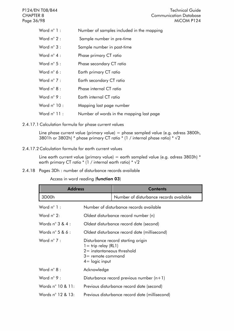
P124/EN T08/B44 Technical Guide CHAPTER 8 Communication Database Page 36/98 MiCOM P124
Word n° 1 : Number of samples included in the mapping
Word n° 2 : Sample number in pre-time
Word n° 3 : Sample number in post-time
Word n° 4 : Phase primary CT ratio
Word n° 5 : Phase secondary CT ratio
Word n° 6 : Earth primary CT ratio
Word n° 7 : Earth secondary CT ratio
Word n° 8 : Phase internal CT ratio
Word n° 9 : Earth internal CT ratio
Word n° 10 : Mapping last page number
Word n° 11 : Number of words in the mapping last page
2.4.17.1 Calculation formula for phase current values
Line phase current value (primary value) = phase sampled value (e.g. adress 3800h, 3801h or 3802h) * phase primary CT ratio * (1 / internal phase ratio) * √2
2.4.17.2 Calculation formula for earth current values
Line earth current value (primary value) = earth sampled value (e.g. adress 3803h) * earth primary CT ratio * (1 / internal earth ratio) * √2
2.4.18 Pages 3Dh : number of disturbance records available
Access in word reading (function 03)
Address Contents
3D00h Number of disturbance records available
Word n° 1 : Number of disturbance records available
Word n° 2: Oldest disturbance record number (n)
Words n° 3 & 4 : Oldest disturbance record date (second)
Words n° 5 & 6 : Oldest disturbance record date (millisecond)
Word n° 7 : Disturbance record starting origin 1= trip relay (RL1) 2= instantaneous threshold 3= remote command 4= logic input
Word n° 8 : Acknowledge
Word n° 9 : Disturbance record previous number (n+1)
Words n° 10 & 11: Previous disturbance record date (second)
Words n° 12 & 13: Previous disturbance record date (millisecond)

Technical Guide P124/EN T08/B44 Communication Database CHAPTER 8 MiCOM P124 Page 37/98
Word n° 14 : Disturbance record starting origin 1= trip relay (RL1) 2= instantaneous threshold 3= remote command 4= logic input
Word n° 15 : Acknowledge
Word n° 16 : Disturbance record previous number (n+2)
Words n° 17 & 18: Previous disturbance record date (second)
Words n° 19 & 20: Previous disturbance record date (millisecond)
Word n° 21 : Disturbance record starting origin 1= trip relay (RL1) 2= instantaneous threshold 3= remote command 4= logic input
Word n° 22 : Acknowledge
Word n° 23 : Disturbance record previous number (n+3)
Words n° 24 & 25: Previous disturbance record date (second)
Words n° 26 & 27: Previous disturbance record date (millisecond)
Word n° 28 : Disturbance record starting origin 1= trip relay (RL1) 2= instantaneous threshold 3= remote command 4= logic input
Word n° 29 : Acknowledge
Word n° 30 : Disturbance record previous number (n+4)
Words n° 31 & 32: Previous disturbance record date (second)
Words n° 33 & 34: Previous disturbance record date (millisecond)
Word n° 35 : Disturbance record starting origin 1= trip relay (RL1) 2= instantaneous threshold 3= remote command 4= logic input
Word n° 36 : Acknowledge

P124/EN T08/B44 Technical Guide CHAPTER 8 Communication Database Page 38/98 MiCOM P124
2.4.19 Description of the mapping format, MiCOM P124 Dual-powered
CODE DESCRIPTION
F1 Unsigned integer numerical data : 1 - 65535
F2 Signed integer numerical data : -32768 - 32767
F3 Unsigned integer curves type 0 : STI (IEC) 1 : SI (IEC) 2 : VI (IEC) 3 : EI (IEC) 4 : LTI (IEC) 5: STI (C02) 6: MI (ANSI) 7 : LTI (CO8) 8 : VI (ANSI) 9 : EI (ANSI) 10 : RC Rectifier curve
F3' Unsigned integer Laborelec curve type 0 : curve 1 1 : curve 2 2 : curve 3
F4 Unsigned integer : MODBUS speed 0 : 300 1 : 600 2 : 1200 3 : 2400 4 : 4800 5 : 9600 6 : 19200 7 : 38400
F5 Unsigned integer : parity 0 : without 1 : even 2 : odd
F6 Unsigned integer : Tripping configuration bit 0 : tI> bit 1 : tI>> bit 2 : tI>>> bit 3 : tlE> bit 4 : tlE >> bit 5 : tlE >>> bit 6 : I< bit 7 : tIth> bit 8 : Broken conductor detection bit 9 : t Aux 1 bit 10 : t Aux 2 bit 11 : tI2> bits 12 to 15 : reserved
F7 Reserved

Technical Guide P124/EN T08/B44 Communication Database CHAPTER 8 MiCOM P124 Page 39/98
CODE DESCRIPTION
F8 Unsigned integer : Latching configuration bit 0 : I> latching bit 1 : I>> bit 2 : I>>> bit 3 : lE> bit 4 : lE>> bit 5 : lE>>> bit 6 : I< bit 7 : tIth> bit 8 : Broken conductor detection bit 9 : t Aux 1 bit 10 : t Aux 2 bit 11 : tI2> bits 12 to 15 : reserved
F8' Unsigned integer : Blocking logic configuration bit 0 : I> blocking bit 1 : I>> bit 2 : I>>> bit 3 : lE> bit 4 : lE>> bit 5 : lE>>> bit 6 : reserved bit 7 : tIth> bit 8 : Broken conductor detection bit 9 : t Aux 1 bit 10 : t Aux 2 bit 11 : tI2> bits 12 to 15 : reserved
F9 Unsigned integer : Remote control 1 bit 0 : Tripping contact delatched bit 1 : 1st
alarm acknowledge bit 2 : All alarms acknowledge bit 3 : Remote tripping bit 4 : Remote closing bit 5 : Setting group change bit 6 : Thermal state reset bit 7 : Peak and rolling value reset bit 8 : Disturbance record remote start bit 9 : Maintenance mode bit 10 : Recloser counter reset bit 11 : Recloser reset bit 12 : Local maintenance acknowledge bit 13 : Oldest event acknowledge bit 14 : Oldest fault acknowledge bit 15 : Hardware Sram alarm acknowledge
F10 2 characters ASCII 32 127 = ASCII character1 32 127 = ASCII character 2
F11 Unsigned integer : triggered output type 0 : stricker output 1 : trip output relay, RL1 2 : stricker + trip output relay RL1 outputs

P124/EN T08/B44 Technical Guide CHAPTER 8 Communication Database Page 40/98 MiCOM P124
CODE DESCRIPTION
F12 Unsigned integer : Logic input status it 0 : logic input number 1 bit 1 : logic input number 2 bit 2 : logic input number 3 bit 3 : logic input number 4 bit 4 : logic input number 5 bits 5 to 15 : reserved
F13 Unsigned integer : logic outputs status bit 0 : watchdog RL0 bit 1 : logic output RL1 (tripping) bit 2 : stricker output bit 3 : V1 flag command bit 4 : V1 flag reset bits 5 to 15 : reserved
F14 Unsigned integer : logic outputs configuration bit 0 : selection logic output number RL2 bit 1 : selection logic output number RL3 bit 2 : selection logic output number RL4 bit 3 : selection logic output number RL5 bit 4 : selection logic output number RL6 bits 5 to 15 : reserved
F15 Unsigned integer : logical input allocation bit 0 : delatch allocation bit 1 : allocation 52 a bit 2 : allocation 52 b bit 3 : allocation external CB failure bit 4 : allocation external input 1 bit 5 : allocation external input 2 bit 6 : allocation logic blocking 1 bit 7 : allocation logic blocking 2 bit 8 : allocation disturbance start bit 9 : allocation cold load start bit 10 : allocation selective scheme logic 1 bit 11 allocation selective scheme logic 2 bit 12 : allocation change of setting group bit 13 : allocation recloser locked bit 14 : allocation thermal state reset bit 15 : allocation trip circuit supervision
F15' Unsigned integer : logical input allocation (next)
bit 0 : start CB fail timer
F16 Unsigned integer : threshold earth information status bit 0 : reserved bit 1 : reserved bit 2 : reserved bit 3 : reserved bit 4 : reserved bit 5 : Instantaneous information IE> or IE>> or IE>>> bit 6 : Tripping information tIE> or tIE>> or tIE>>> bits 7 to 15 : reserved

Technical Guide P124/EN T08/B44 Communication Database CHAPTER 8 MiCOM P124 Page 41/98
CODE DESCRIPTION
F17 Unsigned integer : threshold phase information status bit 0 : reserved bit 1 : Instantaneous IA bit 2 : Instantaneous IB bit 3 : Instantaneous IC bit 4 : reserved bit 5 : Instantaneous information I> or I>> or I>>> bit 6 : Tripping information tI> or tI>> or tI>>> bits 7 to 15 : reserved
F18 Long integer
F19 Unsigned integer : LEDs allocation bit 0 : I> bit 1 : tI> bit 2 : I>> bit 3 : tI>> bit 4 : I>>> bit 5 : tI>>> bit 6 : IE> bit 7 : tIE> bit 8 : IE>> bit 9 : tIE>> bit 10 : IE>>> bit 11 : tIE>>> bit 12 : Thermal overload trip bit 13 : tI2> bit 14 : Broken conductor trip bit 15 : CB failure bit 16 : Logic input 1 bit 17 : Logic input 2 bit 18 : Logic input 3 bit 19 : Logic input 4 bit 20 : Logic input 5 bit 21 : Recloser running bit 22 : Recloser locked bit 23 : t Aux1 bit 24 : t Aux2

P124/EN T08/B44 Technical Guide CHAPTER 8 Communication Database Page 42/98 MiCOM P124
CODE DESCRIPTION
F20 Unsigned integer : logic input data status bit 0 : Selective scheme logic 1 bit 1 : Selective scheme logic 2 bit 2 : Relay delatch bit 3 : CB position (52 a) bit 4 : CB position (52 b) bit 5 : External CB failure bit 6 : External 1 bit 7 : External 2 bit 8 : Blocking logic 1 bit 9 : Blocking logic 2 bit 10 : Disturbance record start bit 11 : Cold load start bit 12 : Setting group change bit 13 : Recloser locked bit 14 : Thermal state reset bit 15 : Trip circuit supervision
F21 Unsigned integer : software version 10 : Version 1.A 11 : Version 1.B 20 : Version 2.A
F22 Unsigned integer : internal logic data bit 0 : Blocking bit 1 : reserved
F23 Unsigned integer : relay status bit 0 : Relay status (major alarm) bit 1 : Minor material alarm bit 2 : Presence of non-acknowledged event bit 3 : Synchronisation state bit 4 : Presence of non-acknowledged disturbance record bit 5 : Presence of non-acknowledged fault record bit 6 : reserved bit 7 : reserved
F24 0 : Out of service 1 : Healthy
F25 2 ASCII characters
F26 1 : IA measurement display (True RMS) 2 : IB measurement display (True RMS) 3 : IC measurement display (True RMS) 4 : IN measurement display (True RMS)
F27 0 : DMT time delay 1 : IDMT time delay 2 : RI time delay
F27' 0 : DMT time delay 1 : IDMT time delay 2 : RI time delay 3 : Laborelec curve
F28 0 : 7 data bits 1 : 8 data bits

Technical Guide P124/EN T08/B44 Communication Database CHAPTER 8 MiCOM P124 Page 43/98
CODE DESCRIPTION
F29 0 : 1 stop bit 1 : 2 stop bits.
F30 0 : Communication non-available 1 : Communication available
F31 Unsigned integer : Number of available event records 0 : None 1 : 1 event record available 2 : 2 event records available 3 : 3 event records available 4 : 4 event records available 5 : 5 event records available
F32 Unsigned integer : 0 : Disturbance record start condition on INSTANTANEOUS 1 : Disturbance record start condition on TRIPPING
F33 Cold load start thresholds bit 0 : tI> bit 1 : tI>> bit 2 : tI>>> bit 3 : tIE> bit 4 : tIE>> bit 5 : tIE>>> bit 6 : Thermal overload trip bit 7 : tI2> bit 8 to 15 : reserved
F34 Reserved
F35 0 : No disturbance record uploaded 1 : Disturbance record upload running
F36 Memorised flags of non acknowledged alarms : bit 0 : IE> bit 1 : tIE> bit 2 : IE>> bit 3 : tIE>> bit 4 : IE>>> bit 5 : tIE>>> bit 6 : Thermal overload alarm bit 7 : Thermal overload trip bit 8 : Broken conductor bit 9 : CB failure bit 10 : reserved bit 11 : I2> bit 12 : tI2> bit 13 : t Aux 1 bit 14 : t Aux 2 bit 15 : reserved
F37 Unsigned integer : Thermal overload information bit 0 : Thermal overload alarm bit 1 : Thermal overload trip

P124/EN T08/B44 Technical Guide CHAPTER 8 Communication Database Page 44/98 MiCOM P124
CODE DESCRIPTION
F38 Unsigned integer : bit 0 : reserved bit 1 : CB failure bit 2 : Pole A opening bit 3 : Pole B opening bit 4 : Pole C opening bit 5 : Broken conductor bit 6 : t Aux 1 bit 7 : t Aux 2 bit 8 : Broken conductor time delay bit 9 : CB failure time delay bit 10 : Cold load pick up time delay bit 11 : CB alarms or bits 0,1,2,4 of F43
F39 Unsigned integer : output relay remote word in maintenance mode bit 0 : RL1 (trip) bit 1 : RL2 bit 2 : RL3 bit 3 : RL0 (watchdog) bit 4 : RL4 bit 5 : RL5 bit 6 : RL6
F40 Unsigned integer : selective scheme logic configuration bit 0 : tI>> bit 1 : tI>>> bit 2 : tlE>> bit 3 : tlE>>
F41 0 : Front and rear MODBUS communication 1 : Front MODBUS and rear Courier communication
F42 5, 10, 15, 30 or 60 minutes
F43 bit 0 : CB operating time overreach bit 1 : CB operation number overreach bit 2 : Square Amps sum overreach bit 3 : Trip circuit self-test bit 4 : CB closing time overreach bits 5 to 10 : Reserved
F44 bit 0 : CB, operating time overreach, memorised alarm bit 1 : CB operation number overreach, memorised alarm bit 2 : Square Amps sum overreach, memorised alarm bit 3 : Trip circuit self-test, memorised alarm bit 4 : CB closing time overreach, memorised alarm bits 5 to 7 : reserved
F45 Unsigned integer : relay status bit 0 : Watchdog bit 1 : Communicatio n failure bit 2 : EEPROM data failure bit 3 : Analogue failure bit 4 : Datation failure bit 5 : EEPROM calibration failure bit 6 : SRAM failure bit 7 : reserved

Technical Guide P124/EN T08/B44 Communication Database CHAPTER 8 MiCOM P124 Page 45/98
CODE DESCRIPTION
F46 bit 0 : Io harmonic calculation bit 1 : trip number reset
F49 bit 0 : cycle 1 configuration (trip followed by reclosing cycle) bit 1 : cycle 1 configuration (no trip in cycle 1) bit 2 to bit 3 : reserved bit 4 : cycle 2 configuration (trip followed by reclosing cycle) bit 5 : cycle 2 configuration (no trip in cycle 2) bit 6 to bit 7 : reserved bit 8 : cycle 3 configuration (trip followed by reclosing cycle) bit 9 : cycle 3 configuration (no trip in cycle 3) bit 10 to bit 11 : reserved bit 12 : cycle 4 configuration (trip followed by reclosing cycle) bit 13 : cycle 4 configuration (no trip in cycle 4)
F50 Unsigned integer : CTs and model configuration "A" : model standard, CT 1A "B" : model standard, CT 5A "C" : model sensitive, CT 1A "D" : model sensitive, CT 5A
F51 Unsigned integer : option configuration 0 : 1 electromagnetic flag 1 : 5 electromagnetic flags 2 : 5 flags + autorecloser
F52 Unsigned integer : electromechanical flags status (P124D)
bit 0 : V2 flag bit 1 : V2 flag reset bit 2 : V3 flag bit 3 : V3 flag reset bit 4 : V4 flag bit 5 : V4 flag reset bit 6 : V5 flag bit 7 : V5 flag reset
F53 Unsigned integer : internal data 2
bit 0 : CB fail by external input
F54 Unsigned integer : datation format
0 : private format 1 : IEC format
F55 0 : setting group change either on edge of digital input, or on remote command, or of the relay front 1 : setting group change on level of digital input

P124/EN T08/B44 Technical Guide CHAPTER 8 Communication Database Page 46/98 MiCOM P124
2.4.20 Disturbance record additional information
2.4.20.1 MODBUS request definition used for disturbance record
To upload a disturbance record, the following requests must be done in the exact given order :
1. (optional) : Send a request to know the number of disturbance records available in SRAM.
2. (compulsory) : Send a request with the record number and the channel number.
3. (compulsory) : Send one or several requests to upload the disturbance record data. It depends of the number of samples.
4. (compulsory) : Send a request to upload the index frame.
2.4.20.2 Request to know the number of disturbance records in SRAM
Slave number Function code Word address Word number CRC
xx 03h 3Dh 00 00 24h xx xx
This request may be answered an error message with the error code :
EVT_NOK(OF) : No record available
NOTA : If there is less than 5 records available, the answer will contains zero in the non-used words.
2.4.20.3 Service requests
This request must be send before uploading the disturbance record channel samples. It allows to know the record number and the channel number to upload. It allows also to know the number of samples in the channel.
Slave number Function code Word address Word number CRC
xx 03h Refer to mapping
00 0Bh xx xx
This request may be answered an error message with two different error codes :
CODE_DEF_RAM(02) : SRAM failure
CODE_EVT_NOK(03) : no disturbance record available in SRAM

Technical Guide P124/EN T08/B44 Communication Database CHAPTER 8 MiCOM P124 Page 47/98
2.4.20.4 Disturbance record upload request
Slave number Function code Word address Word number CRC
xx 03h Refer to mapping
01 to 7Dh xx xx
This request may be answered an error message with two different error codes :
CODE_DEP_DATA(04) : the required disturbance data number is greater than the memorised number.
CODE_SERV_NOK(05) : the service request for disturbance record and channel number has not been send.
2.4.20.5 Index frame upload request
Slave number Function code Word address Word number CRC
xx 03h 22h 00 00 07h xx xx
This request may be answered an error message with an error code :
CODE_SERV_NOK(05) : the service request for disturbance record and channel number has not been send.
Two ways can be followed to retrieve an event record :
− Send a request to retrieve the oldest non-acknowledge event.
− Send a request to retrieve a dedicated event.
2.4.21 Request to retrieve the oldest non-acknowledge event
Slave number Function code Word address Word number CRC
xx 03h 36h 00 00 09h xx xx
This event request may be answered an error message with the error code :
EVT_EN_COURS_ECRIT (5) : An event is being written into the saved RAM.
NOTA : On event retrieval, two possibilities exist regarding the event record acknowledgement : a) Automatic event record acknowledgement on event retrieval. b) Non automatic event record acknowledgement on event retrieval.
a) Automatic event record acknowledgement on event retrieval :
The bit12 of the remote order frame (format F9 mapping address 0400h) shall be set to 0. On event retrieval, this event record is acknowledged.
b) Non automatic event record acknowledgement on event retrieval :
The bit12 of the remote order frame (format F9 mapping address 0400h) shall be set to 1. On event retrieval, this event record is not acknowledged. To acknowledge this event, an other remote order shall be sent to the relay. The bit 13 of this frame (format F9 mapping address 0400h) shall be set to 1.

P124/EN T08/B44 Technical Guide CHAPTER 8 Communication Database Page 48/98 MiCOM P124
2.4.22 Request to retrieve a dedicated event
Slave number Function code Word address Word number CRC
xx 03h Refer to mapping
00 09h xx xx
This event request may be answered an error message with the error code :
EVT_EN_COURS_ECRIT (5) : An event is being written into the saved RAM.
NOTA : This event retrieval does not acknowledge this event.
2.4.23 Modbus request definition used to retrieve the fault records
Two ways can be followed to retrieve a fault record :
− Send a request to retrieve the oldest non-acknowledge fault record.
− Send a request to retrieve a dedicated fault record.
2.4.23.1 Request to retrieve the oldest non-acknowledge fault record
Slave number Function code Word address Word number CRC
xx 03h 3Eh 00 00 0Fh xx xx
NOTA : On fault retrieval, two possibilities exist regarding the fault record acknowledgement: a) Automatic fault record acknowledgement on event retrieval. b) Non automatic fault record acknowledgement on event retrieval.
a) Automatic fault record acknowledgement on fault retrieval :
The bit12 of the remote order frame (format F9 mapping address 0400h) shall be set to 0. On fault retrieval, this fault record is acknowledged.
b) Non automatic fault record acknowledgement on fault retrieval :
The bit12 of the remote order frame (format F9 mapping address 0400h) shall be set to 1. On fault retrieval, this fault record is not acknowledged. To acknowledge this fault, an other remote order shall be sent to the relay. The bit 14 of this frame (format F9 mapping address 0400h) shall be set to 1.
2.4.23.2 Request to retrieve a dedicated fault record
Slave number Function code Word address Word number CRC
xx 03h Refer to mapping
00 0Fh xx xx
NOTA : This fault value retrieval does not acknowledge this fault record.

Technical Guide P124/EN T08/B44 Communication Database CHAPTER 8 MiCOM P124 Page 49/98
3. K-BUS PROTOCOL AND COURIER LANGUAGE
The serial communications are transmitted on K-Bus, a multi-drop network proposin an instantaneous interface with IEC 870 - 5 - FT1.2 standards. The language and th communication protocol used are Courier. This concept permits especially to the generic programmes of the principal units to access to a high number of different relay types without need to change permanently the principal unit program for each relay type. The relays forms a distributed database in which the principal workstation proceeds to a selective call of the slave relays in order to know all necessary information.
Courier has a concept for the functions with a selective call system which allows not a slave periphery to communicate directly with the central unit when one shall informs another about a particular event. The slave workstation has to wait that the principal workstation asks for the information. With Courier each information is given into a box with a code of the length and the database type. In knowing the database format the reception periphery can read them.
3.1 K-BUS
K-Bus is a communication system developed for connecting the slave peripheries in remoting on the central unit, permitting them to execute all remote monitoring and remote control functions using the appropriated communication language. K-Bus is not able to permit a direct communication between the slave peripheries. Only a communication between the central unit and the slave peripheries can be established. The principal characteristics of the K-Bus are his profitability, his high security level, his installation facility and his user friendliness.
3.1.1 K-Bus transmission layer
The communication port is supported on the reception levels and the voltage transmission RS485 with galvanic isolation assured by a transformer. A selective call protocol is used. No relay unit is allowed to transmit before having received a validation message without any error detection. The transmission is synchronous on a pair of isolated waves. The data are coded FM0 with a clock signal for eliminate all CC-component, allows the signal to cross the transformers.
With the exception of the central units, each network node is passive. No defective unit from the system can interfere with the communications established with the other units. The message format is HDLC. The data transmission speed is 64 kbits/s.
3.1.2 K-Bus connection
The connection on the K-Bus port is realised by screwed terminals of 4 mm of MIDOS standards or by FASTON-connectors. A cabled pair is sufficient to realise the connection, knowing that the polarity is not important. It is recommended to use an external screen earth linked at the end of the principal workstation only. The screen has to be fixed with a M4 screw following the wiring scheme (cf. Appendice 1 of the Technical Guide). The functioning of the K-BUS network is guaranteed for 32 units connected on 1000 meters of cables. Thanks to the data code method, the polarity of the Bus cable connection is not important.
NOTE : The K-Bus network has to finish with a 150 ohms resistance on each end of the Bus. The principal workstation can be placed anywhere on the network. This command point has to be unique

P124/EN T08/B44 Technical Guide CHAPTER 8 Communication Database Page 50/98 MiCOM P124
3.1.3 Auxiliary equipment
For communication with the relay it is necessary to have at least one converter case K-Bus/IEC870-5 of the type KITZ and a computer suitable software, an interconnection cable RS232 for connecting the KITZ to the computer and a software conform to the specification of the Courier protocol.
3.2 Relay courier database
The Courier database is two dimensional structure with each cell in the database being referenced by a row and column address. Both the column and the row can take a range from 0 to 255. Addresses in the database are specified as hexadecimal values, eg 0A02 is column 0A (10 decimal) row 02. Associated settings/data will be part of the same column, row zero of the column contains a text string to identify the contents of the column.

Tech
nica
l Gui
de
P1
24/E
N T
08/B
44
Com
mun
icat
ion
Dat
abas
e
CH
APT
ER 8
M
iCO
M P
124
Pa
ge 5
1/98
3.2.
1 C
ell r
efer
ence
Col
Ro
w
Men
u T
ext
Data
Typ
e
Ind
Valu
es
(* :
def
au
lt)
Dep
end
Cel
l Typ
e M
in/M
ax/
Step
00
00
SYST
EM D
ATA
01
La
ngua
ge
Ver>
: In
dexe
d St
ring
0 1 2 3
Lang
1 (F
renc
h)
Lang
2 (E
nglis
h) *
La
ng3
(Ger
man
) La
ng4
(Spa
nish
)
Se
tting
0/
3/1
02
Pa
ssw
ord
ASC
II Pa
ssw
ord(
4 by
tes)
AA
AA
Setti
ng
32/1
27/1
03
Fn
links
: NO
N IM
PLEM
ENTE
04
D
escr
iptio
n A
SCII
Text
(6 b
ytes
)
P1
24-D
*
Se
tting
32
/127
/1
05
Pl
ant R
efer
ence
A
SCII
Text
(4 b
ytes
)
Pr
ef
Setti
ng
32/1
27/1
06
M
odel
Num
ber
ASC
II Te
xt (1
6 by
tes)
M
odel
Num
ber
Dat
a
07
Fi
rmw
are
Num
ber
ASC
II Te
xt (1
6 by
tes)
Fi
rmw
are
Num
ber
Dat
a
08
Se
rial N
umbe
r A
SCII
Text
(16
byte
s)
Seria
l Num
ber
Dat
a
09
Fr
eque
ncy
Uns
igne
d In
tege
r (2
byt
es)
XX
XX H
z
Setti
ng
50/6
0/10
0A
C
omm
unic
atio
n Le
vel
Uns
igne
d In
tege
r (2
byt
es)
1
D
ata
0B
A
ddre
ss
Uns
igne
d In
tege
r (2
byt
es)
1*
Setti
ng
1/25
5/1
0C
Pl
ant S
tatu
s W
ord:
NO
N IM
PLEM
ENTE
0D
C
ontr
ol S
tatu
s W
ord:
NO
N IM
PLEM
ENTE
0E
Se
tting
Gro
up
Uns
igne
d In
tege
r
Dat
a
0F
Lo
ad s
hed
Stag
e: N
ON
IMPL
EMEN
TE
10
C
ircui
t Bre
aker
Con
trol
A
1+, A
2: N
ON
IMPL
EMEN
TE
11
So
ftwar
e Re
fere
nce
ASC
II Te
xt (1
6 ch
arac
ters
)
Dat
a
12
-1F
Unu
sed,
res
erve
d
20
Lo
gic
Inpu
t Sta
tus
Bina
ry fl
ag (5
bits
)
0: lo
g in
put 1
1:
log
inpu
t 2
2: lo
g in
put 3
3:
log
inpu
t 4
4: lo
g in
put 5
D
ata

P124
/EN
T08
/B44
Tech
nica
l Gui
de
CH
APT
ER 8
Com
mun
icat
ion
Dat
abas
e Pa
ge 5
2/98
MiC
OM
P12
4
Col
Ro
w
Men
u T
ext
Data
Typ
e
Ind
Valu
es
(* :
def
au
lt)
Dep
end
Cel
l Typ
e M
in/M
ax/
Step
21
Re
lay
Out
put S
tatu
s Bi
nary
flag
(7 b
its)
0:
rel
ay 1
(trip
)
1: w
atch
dog
rela
y
2: r
elay
2
3: r
elay
3
4: r
elay
4
5 :
rela
y 5
6 :
rela
y 6
D
ata
22
Ala
rm
Bina
ry fl
ag (1
6 bi
ts)
0:
res
erve
d 1:
Com
m e
rr
2:
Eep
rom
err
dat
a 3:
Ct e
rror
4:
Eep
rom
err
cal
ib
5: C
lock
err
or
6: B
bram
err
or
7 to
15:
res
erve
d
D
ata
23
Pseu
do L
ogic
Inpu
t Sta
tus
grou
p 1
Bina
ry fl
ag (1
6 bi
ts)
0:
I>
1: I>
>
2: I>
>>
3:
I0>
4:
I0>
>
5: I0
>>
>
6: t
I>
7: t
I>>
8:
t I>
>>
9:
t I0
>
10:
t I0>
>
11:
t I0>
>>
12
: Th
erm
al A
larm
13
: Th
erm
. Ove
rload
14
: t I
<
15:
rese
rved
D
ata

Tech
nica
l Gui
de
P1
24/E
N T
08/B
44
Com
mun
icat
ion
Dat
abas
e
CH
APT
ER 8
M
iCO
M P
124
Pa
ge 5
3/98
Col
Ro
w
Men
u T
ext
Data
Typ
e
Ind
Valu
es
(* :
def
au
lt)
Dep
end
Cel
l Typ
e M
in/M
ax/
Step
24
Pseu
do L
ogic
Inpu
t Sta
tus
grou
p 2
Bina
ry fl
ag (1
6 bi
ts)
0:
Bro
ken
Con
duct
or
1: t
Aux
1
2: t
Aux
2
3: B
reak
er F
ail.
4: Ii
nv >
5:
t Iin
v>
6: O
pen
oper
atin
g tim
e 7:
Trip
ope
ratio
n N
b 8:
SA
2 n
9:
SW
Trip
Circ
uit
10:
Clo
se o
pera
ting
time
11:
Succ
essf
ul
auto
recl
ose
12:
Lock
ed a
utor
eclo
ser
13:
Aut
orec
lose
r co
nf. f
ail
14:
rese
rved
15
: re
serv
ed
D
ata
01
00
USE
R C
ON
TRO
L
01
Re
mot
e co
ntro
l 1
Bina
ry fl
ag (1
5 bi
ts)
0:
Unl
ock
trip
con
t.*
1: A
ck fi
rst a
larm
2
: A
ck a
ll al
arm
s 3
: TR
IP
4 :
CLO
SE
5 :
Setti
ng C
hang
e 6
: Th
. Sta
te R
eset
7
: RM
S ov
er&
max
Res
et
8 :
Dis
t. Re
c. T
rig
9 :
Mai
nten
ance
Sta
rt
10 :
Rec
lose
r tim
er R
eset
11
: R
eclo
ser
Rese
t 12
: M
anua
l Ack
mod
e 13
: A
ck. o
lder
eve
nt
14 :
Ack
. old
er d
efau
lt 15
: S
RAM
def
. a
ck.
Se
tting
0/
6553
5/1

P124
/EN
T08
/B44
Tech
nica
l Gui
de
CH
APT
ER 8
Com
mun
icat
ion
Dat
abas
e Pa
ge 5
4/98
MiC
OM
P12
4
Col
Ro
w
Men
u T
ext
Data
Typ
e
Ind
Valu
es
(* :
def
au
lt)
Dep
end
Cel
l Typ
e M
in/M
ax/
Step
02
Re
mot
e co
ntro
l 2
Bina
ry fl
ag (1
0 bi
ts)
0
: Re
serv
ed
1 :
Rese
rved
2
: Re
serv
ed
3 :
Rela
y :
Spec
ial
Trip
ping
4
: W
atch
dog
Rela
y 5
: Re
lay
1 6
: Re
lay
2 7
: Re
lay
3 8
: Re
lay
4 9
: Re
lay
5
Se
tting
0/
1023
/1
03
Re
mot
e co
ntro
l 3
Bina
ry fl
ag (2
bits
)
0 :
Rese
t I0
Har
mon
ic
1 :
Unl
ock
TRIP
Rel
ay
Se
tting
0/
3/1
02
00
VIE
W R
ECO
RD
S
01
Re
cord
num
ber
Uns
igne
d In
tege
r (2
byt
es)
5 Se
tting
1/
5/1
02
O
ccur
dat
e U
nsig
ned
Inte
ger
(2 b
ytes
)
03
A
ctiv
e se
t gro
up
Uns
igne
d In
tege
r (2
byt
es)
04
Ph
ase
in fa
ult
ASC
II Te
xt
05
Fa
ult I
d A
SCII
Text
06
M
agni
tude
C
ourie
r flo
atin
g po
int
num
ber
07
Ia
mag
nitu
de
Cou
rier
float
ing
poin
t nu
mbe
r
08
Ib
mag
nitu
de
Cou
rier
float
ing
poin
t nu
mbe
r
09
Ic
mag
nitu
de
Cou
rier
float
ing
poin
t nu
mbe
r
0A
In
mag
nitu
de
Cou
rier
float
ing
poin
t nu
mbe
r

Tech
nica
l Gui
de
P1
24/E
N T
08/B
44
Com
mun
icat
ion
Dat
abas
e
CH
APT
ER 8
M
iCO
M P
124
Pa
ge 5
5/98
Col
Ro
w
Men
u T
ext
Data
Typ
e
Ind
Valu
es
(* :
def
au
lt)
Dep
end
Cel
l Typ
e M
in/M
ax/
Step
03
00
MEA
SUREM
ENTS
01
IA
RM
S C
ourie
r flo
atin
g po
int
num
ber
D
ata
02
IB
RM
S C
ourie
r flo
atin
g po
int
num
ber
D
ata
03
IC
RM
S C
ourie
r flo
atin
g po
int
num
ber
D
ata
04
I0
RM
S C
ourie
r flo
atin
g po
int
num
ber
D
ata
05
Id
irect
C
ourie
r flo
atin
g po
int
num
ber
D
ata
06
IIN
V C
ourie
r flo
atin
g po
int
num
ber
D
ata
07
Ra
tio Id
ir /
Iinv
Cou
rier
float
ing
poin
t nu
mbe
r
Dat
a
08
TH
ERM
AL
STA
TE (
Rst
) U
nsig
ned
Inte
ger
(2 b
ytes
) (%
)
Dat
a
09
FR
EQU
ENC
Y C
ourie
r flo
atin
g po
int
num
ber
D
ata
0A
Rst
MA
X &
MO
Y RM
S
0B
M
AX
RMS
IA
Cou
rier
float
ing
poin
t nu
mbe
r
Dat
a
0C
M
AX
RMS
IB
Cou
rier
float
ing
poin
t nu
mbe
r
Dat
a
0D
M
AX
RMS
IC
Cou
rier
float
ing
poin
t nu
mbe
r
Dat
a
0E
IA
RM
S A
VERA
GE
Cou
rier
float
ing
poin
t nu
mbe
r
Dat
a
0F
IB
RM
S A
VERA
GE
Cou
rier
float
ing
poin
t nu
mbe
r
Dat
a
10
IC
RM
S A
VERA
GE
Cou
rier
float
ing
poin
t nu
mbe
r
Dat
a
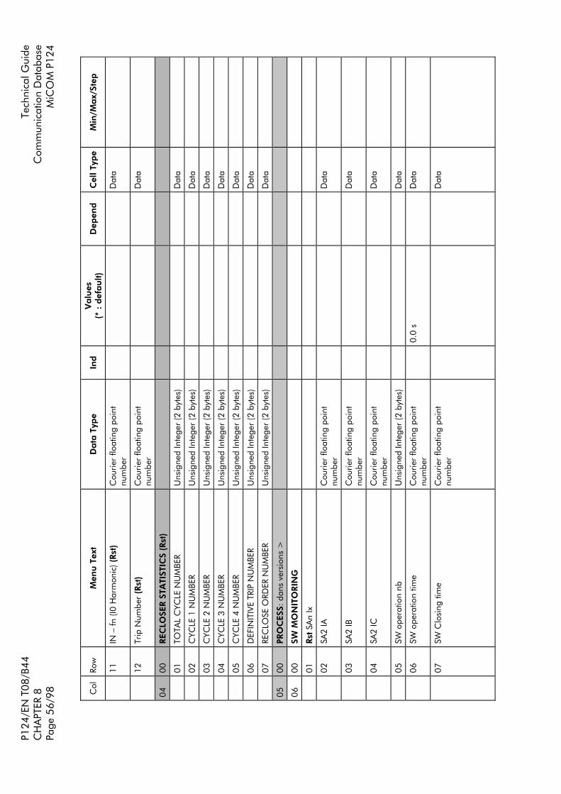
P124
/EN
T08
/B44
Tech
nica
l Gui
de
CH
APT
ER 8
Com
mun
icat
ion
Dat
abas
e Pa
ge 5
6/98
MiC
OM
P12
4
Col
Ro
w
Men
u T
ext
Data
Typ
e
Ind
Valu
es
(* :
def
au
lt)
Dep
end
Cel
l Typ
e M
in/M
ax/
Step
11
IN
fn
(I0
Har
mon
ic) (
Rst
) C
ourie
r flo
atin
g po
int
num
ber
D
ata
12
Tr
ip N
umbe
r (R
st)
Cou
rier
float
ing
poin
t nu
mbe
r
Dat
a
04
00
REC
LOSE
R S
TATI
STIC
S (R
st)
01
TO
TAL
CYC
LE N
UM
BER
Uns
igne
d In
tege
r (2
byt
es)
D
ata
02
C
YCLE
1 N
UM
BER
Uns
igne
d In
tege
r (2
byt
es)
D
ata
03
C
YCLE
2 N
UM
BER
Uns
igne
d In
tege
r (2
byt
es)
D
ata
04
C
YCLE
3 N
UM
BER
Uns
igne
d In
tege
r (2
byt
es)
D
ata
05
C
YCLE
4 N
UM
BER
Uns
igne
d In
tege
r (2
byt
es)
D
ata
06
D
EFIN
ITIV
E TR
IP N
UM
BER
Uns
igne
d In
tege
r (2
byt
es)
D
ata
07
RE
CLO
SE O
RDER
NU
MBE
R U
nsig
ned
Inte
ger
(2 b
ytes
)
Dat
a
05
00
PRO
CES
S: d
ans
vers
ions
>
06
00
SW M
ON
ITO
RIN
G
01
Rst
SA
n Ix
02
SA
2 IA
C
ourie
r flo
atin
g po
int
num
ber
D
ata
03
SA
2 IB
C
ourie
r flo
atin
g po
int
num
ber
D
ata
04
SA
2 IC
C
ourie
r flo
atin
g po
int
num
ber
D
ata
05
SW
ope
ratio
n nb
U
nsig
ned
Inte
ger
(2 b
ytes
)
Dat
a
06
SW
ope
ratio
n tim
e C
ourie
r flo
atin
g po
int
num
ber
0.
0 s
D
ata
07
SW
Clo
sing
tim
e C
ourie
r flo
atin
g po
int
num
ber
D
ata

Tech
nica
l Gui
de
P1
24/E
N T
08/B
44
Com
mun
icat
ion
Dat
abas
e
CH
APT
ER 8
M
iCO
M P
124
Pa
ge 5
7/98
Col
Ro
w
Men
u T
ext
Data
Typ
e
Ind
Valu
es
(* :
def
au
lt)
Dep
end
Cel
l Typ
e M
in/M
ax/
Step
08
00
TIM
E:
01
D
ate/
Tim
e IE
C87
0 Ti
me
& D
ate
D
ata
0E
00
CT
RA
TIO
S
01
Ph
ase
CT
Prim
ary
Uns
igne
d In
tege
r (2
byt
es)
10
00 *
Setti
ng
1/99
99/1
03
N
eutr
al C
T Pr
imar
y U
nsig
ned
Inte
ger
(2 b
ytes
)
1000
*
Se
tting
1/
9999
/1
0F
00
SETT
ING
GRO
UPS
01
Se
lect
set
ting
grou
p U
nsig
ned
Inte
ger
(2 b
ytes
)
1*
Se
tting
1/
2
02
G
roup
1 v
isib
le
Inde
xed
Strin
g
0 :
YES
* 1
: N
O
Se
tting
0
(YES
) / 1
(NO
)
03
G
roup
2 v
isib
le
Inde
xed
Strin
g
0 :
YES
1 :
NO
*
Se
tting
0
(YES
) / 1
(NO
)
Prote
ctio
n G
rou
p n
° 1
20
00
PHA
SE O
VER
CU
RREN
T
01
St
age
1 O
verc
urre
nt
(Sub
Hea
ding
)
02
M
ax I>
Bi
nary
(1 b
it)
0 D
isab
led
* /
Enab
led
Se
tting
0/
1/1
03
Th
resh
old
I>
Cou
rier
float
ing
poin
t nu
mbe
r
0.1
In *
20
02=
1 Se
tting
0.
1/4.
0/0.
1
04
Te
mpo
risat
ion
Type
In
dexe
d St
ring
0 1 2
0: d
efin
ite ti
me
* 1
: in
vers
e tim
e 2:
RI c
urve
2002
=1
Setti
ng
0/2/
1
05
C
urve
type
In
dexe
d St
ring
0 1 2 3 4 5 6 7 8 9
STI (
CEI
) *
SI (C
EI)
VI (C
EI)
EI (C
EI)
LTI (
CEI
) ST
I (C
O2)
M
I (A
NSI
) LT
I (C
O8)
VI
(AN
SI)
EI (A
NSI
)
2004
=1
Setti
ng
0/9/
1
06
TM
S C
ourie
r flo
atin
g po
int
num
ber
0.
025
* 20
04=
1 Se
tting
0.
025/
1.5/
0.02
5

P124
/EN
T08
/B44
Tech
nica
l Gui
de
CH
APT
ER 8
Com
mun
icat
ion
Dat
abas
e Pa
ge 5
8/98
MiC
OM
P12
4
Col
Ro
w
Men
u T
ext
Data
Typ
e
Ind
Valu
es
(* :
def
au
lt)
Dep
end
Cel
l Typ
e M
in/M
ax/
Step
07
K
Cou
rier
float
ing
poin
t nu
mbe
r
0.1
* 20
04=
2 Se
tting
0.
1/10
.0/0
.005
08
Te
mpo
I>
Cou
rier
float
ing
poin
t nu
mbe
r
0.01
s *
20
04=
0 Se
tting
0/
180.
0/0.
01
09
Te
mpo
res
et ty
pe
Inde
xed
Strin
g
0 :
defin
ite ti
me
1 :
inve
rse
time
2004
=1
and
2005
>=
5
and
2005
<
= 9
Setti
ng
0/1
0A
RT
MS
Cou
rier
float
ing
poin
t nu
mbe
r
0.02
5 *
2009
= 1
Se
tting
0.
025/
1.5/
0.02
5
0B
T
RESE
T C
ourie
r flo
atin
g po
int
num
ber
0.
04 *
20
09 =
0
Setti
ng
0.04
/100
/0.0
1
0C
-0F
Rese
rved
10
St
age
2 O
verc
urre
nt
(Sub
Hea
ding
)
11
M
ax I>
>
Bina
ry (1
bit)
0
Dis
able
d *
/ En
able
d
Setti
ng
0/1/
1
12
Th
resh
old
I>>
C
ourie
r flo
atin
g po
int
num
ber
0.
50 In
*
2011
=1
Setti
ng
0.5/
40.0
/0.0
5
13
Te
mpo
I>>
C
ourie
r flo
atin
g po
int
num
ber
0.
01 s
*
2011
=1
Setti
ng
0/18
0.0/
0.01
14
-1F
Rese
rved
20
St
age
3 O
verc
urre
nt
(Sub
Hea
ding
)
21
M
ax I>
>>
Bi
nary
(1 b
it)
0 D
isab
led
* /
Enab
led
Se
tting
0/
1/1
22
Th
resh
old
I>>
>
Cou
rier
float
ing
poin
t nu
mbe
r
0.50
In *
20
21=
1 Se
tting
0.
5/40
.0/0
.05
23
Te
mpo
I>>
>
Cou
rier
float
ing
poin
t nu
mbe
r
0.01
s *
20
21=
1 Se
tting
0/
180.
0/0.
01
21
00
EARTH
FA
ULT
01
St
age
1 O
verc
urre
nt
(Sub
Hea
ding
)
02
M
ax I0
>
Bina
ry (1
bit)
0
Dis
able
d *
/ En
able
d
Setti
ng
0/1/
1
03
Th
resh
old
I0>
C
ourie
r flo
atin
g po
int
num
ber
0.
01 I0
n*
2102
=1
Setti
ng
0.01
/1.0
/0.0
05

Tech
nica
l Gui
de
P1
24/E
N T
08/B
44
Com
mun
icat
ion
Dat
abas
e
CH
APT
ER 8
M
iCO
M P
124
Pa
ge 5
9/98
Col
Ro
w
Men
u T
ext
Data
Typ
e
Ind
Valu
es
(* :
def
au
lt)
Dep
end
Cel
l Typ
e M
in/M
ax/
Step
04
Te
mpo
Typ
e In
dexe
d St
ring
0 1 2
0: d
efin
ite ti
me
* 1:
inve
rse
time
2: R
I cur
ve
2102
=1
Setti
ng
0/2/
1
05
C
urve
Typ
e
Inde
xed
Strin
g 0 1 2 3 4 5 6 7 8 9
STI (
CEI
) *
SI (C
EI)
VI (C
EI)
EI (C
EI)
LTI (
CEI
) ST
I (C
O2)
M
I (A
NSI
) LT
I (C
O8)
VI
(AN
SI)
EI (A
NSI
)
2104
=1
Setti
ng
1/10
/1
06
TM
S C
ourie
r flo
atin
g po
int
num
ber
0.
025
* 21
04=
1 Se
tting
0.
025/
1.5/
0.02
5
07
K
Cou
rier
float
ing
poin
t nu
mbe
r
0.1
* 21
04=
2 Se
tting
0.
1/10
.0/0
.005
08
Te
mpo
I0>
C
ourie
r flo
atin
g po
int
num
ber
0.
01 s
*
2104
=0
Setti
ng
0/18
0.0/
0.01
09
Te
mpo
res
et T
ype
Inde
xed
Strin
g
0 :
def
inite
tim
e 1
: in
vers
e tim
e 21
04=
1 an
d 21
05 >
= 5
an
d 21
05
<=
9
Setti
ng
0/1
0A
RT
MS
Cou
rier
float
ing
poin
t nu
mbe
r
0.02
5 *
2109
= 1
Se
tting
0.
025/
3.2/
0.02
5
0B
T
RESE
T C
ourie
r flo
atin
g po
int
num
ber
0.
04 *
21
09 =
0
Setti
ng
0.04
/100
/0.0
1
0C
-0F
Rese
rved
10
St
age
2 O
verc
urre
nt
(Sub
Hea
ding
)
11
M
ax I0
>>
Bi
nary
(1 b
it)
0 D
isab
led
* /
Enab
led
Se
tting
0/
1/1
12
Th
resh
old
I0>
>
Cou
rier
float
ing
poin
t nu
mbe
r
0.01
I0n*
21
11=
1 Se
tting
0.
01/8
.0/0
.005

P124
/EN
T08
/B44
Tech
nica
l Gui
de
CH
APT
ER 8
Com
mun
icat
ion
Dat
abas
e Pa
ge 6
0/98
MiC
OM
P12
4
Col
Ro
w
Men
u T
ext
Data
Typ
e
Ind
Valu
es
(* :
def
au
lt)
Dep
end
Cel
l Typ
e M
in/M
ax/
Step
13
Te
mpo
I0>
>
Cou
rier
float
ing
poin
t nu
mbe
r
0.01
s *
21
11=
1 Se
tting
0/
180.
0/0.
01
14
-1F
Rese
rved
20
St
age
3 O
verc
urre
nt
(Sub
Hea
ding
)
21
M
ax I0
>>
>
Bina
ry (1
bit)
0
Dis
able
d *
/ En
able
d
Setti
ng
0/1/
1
22
Th
resh
old
I0>
>>
C
ourie
r flo
atin
g po
int
num
ber
0.
01 I0
n *
2121
=1
Setti
ng
0.01
/8.0
/0.0
05
23
Te
mpo
I0>
>>
C
ourie
r flo
atin
g po
int
num
ber
0.
01 s
*
2121
=1
Setti
ng
0/18
0.0/
0.01
22
00
THER
MA
L O
VER
LOA
D
01
Ith
>
Bina
ry (1
bit)
0
Dis
able
d *
/ En
able
d
Setti
ng
0/1/
1
02
Th
resh
old
Ith>
C
ourie
r flo
atin
g po
int
num
ber
0.
20 It
h*
2201
=1
Setti
ng
0.01
/3.2
/0.0
1
03
K
Ith>
C
ourie
r flo
atin
g po
int
num
ber
1.
05 *
22
01=
1 Se
tting
1.
0/1.
50/0
.01
In
04
θ
TRIP
U
nsig
ned
Inte
ger
(2 b
ytes
)
100
% *
22
01=
1 Se
tting
50
/ 2
00/
1 %
05
θ
ALA
RM ?
Bi
nary
(1 b
it)
0 D
isab
led
* /
Enab
led
2201
=1
Setti
ng
0/1/
1
06
θ
ALA
RM
Uns
igne
d In
tege
r (2
byt
es)
90
% *
22
05 =
1 Se
tting
50
/ 2
00/
1 %
07
Th
erm
al c
onst
ant
Uns
igne
d In
tege
r (2
byt
es)
1
* 22
01=
1 Se
tting
1/
200
/ 1
mn
23
00
MIN
I<
01
I<
Bi
nary
(1 b
it)
0 D
isab
led
* /
Enab
led
Se
tting
0/
1/1
02
Th
resh
old
I<
Uns
igne
d In
tege
r (2
byt
es)
20
%In
*
2301
=1
Setti
ng
2 /
100
/ 1
%In
24
00
NEG
ATI
VE
CU
RREN
T
01
Iin
v>
Bina
ry (1
bit)
0
Dis
able
d *
/ En
able
d
Setti
ng
0/1/
1
02
Th
resh
old
Iinv>
C
ourie
r flo
atin
g po
int
num
ber
0.
1 In
*
2401
= 1
Se
tting
0.
1/40
.0/0
.01
In
03
Te
mpo
risat
ion
Type
In
dexe
d St
ring
0 1 2
0: d
efin
ite ti
me
* 1:
inve
rse
time
2: R
I cur
ve
2401
= 1
Se
tting
0/
2/1

Tech
nica
l Gui
de
P1
24/E
N T
08/B
44
Com
mun
icat
ion
Dat
abas
e
CH
APT
ER 8
M
iCO
M P
124
Pa
ge 6
1/98
Col
Ro
w
Men
u T
ext
Data
Typ
e
Ind
Valu
es
(* :
def
au
lt)
Dep
end
Cel
l Typ
e M
in/M
ax/
Step
04
C
urve
type
In
dexe
d St
ring
0 1 2 3 4 5 6 7 8 9
STI (
CEI
) *
SI (C
EI)
VI (C
EI)
EI (C
EI)
LTI (
CEI
) ST
I (C
O2)
M
I (A
NSI
) LT
I (C
O8)
VI
(AN
SI)
EI (A
NSI
)
2401
= 1
Se
tting
0/
9/1
05
TM
S C
ourie
r flo
atin
g po
int
num
ber
0.
025
* 24
03=
1 Se
tting
0.
025/
1.5/
0.02
5
06
K
(RI)
Cou
rier
float
ing
poin
t nu
mbe
r
0.1
* 24
03=
2 Se
tting
0.
1/10
.0/0
.005
07
Te
mpo
Iinv
>
Cou
rier
float
ing
poin
t nu
mbe
r
0.01
s *
24
03=
0 Se
tting
0/
180.
0/0.
01
08
Re
set t
empo
type
In
dexe
d St
ring
0
: de
finite
tim
e 1
: in
vers
e tim
e 24
03=
1 an
d 24
04 >
= 5
an
d 24
04
<=
9
Setti
ng
0/1/
1
09
RT
MS
Cou
rier
float
ing
poin
t nu
mbe
r
0.02
5 *
2408
= 1
Se
tting
0.
025/
3.2/
0.02
5
0A
T
RESE
T C
ourie
r flo
atin
g po
int
num
ber
0.
04 *
24
08 =
0
Setti
ng
0.04
/100
/0.0
1
25
00
AU
TOREC
LOSE
R
01
A
utor
eclo
ser
Bina
ry (1
bit)
0
Dis
able
d *
/ En
able
d
Setti
ng
0/1/
1
02
St
ate
circ
uit b
reak
er
Bina
ry (1
bit)
Dis
able
d *
/ En
able
d 25
01 =
1
Setti
ng
0/1/
1
03
C
ontr
ol w
indo
w
Cou
rier
float
ing
poin
t nu
mbe
r
0.01
s *
25
02 =
1
Setti
ng
0.01
/ 6
00.0
0 /
0.01
s
04
Ex
tern
al b
lock
ing
Bina
ry (1
bit)
Dis
able
d *
/ En
able
d 25
01 =
1
Setti
ng
0/1/
1
07
Te
mpo
risat
ion
cyc
le 1
C
ourie
r flo
atin
g po
int
num
ber
0.
01 s
*
2501
= 1
Se
tting
0.
01 /
300
.00
/ 0.
01 s

P124
/EN
T08
/B44
Tech
nica
l Gui
de
CH
APT
ER 8
Com
mun
icat
ion
Dat
abas
e Pa
ge 6
2/98
MiC
OM
P12
4
Col
Ro
w
Men
u T
ext
Data
Typ
e
Ind
Valu
es
(* :
def
au
lt)
Dep
end
Cel
l Typ
e M
in/M
ax/
Step
08
Te
mpo
risat
ion
cyc
le 2
C
ourie
r flo
atin
g po
int
num
ber
0.
01 s
*
2501
= 1
Se
tting
0.
01 /
300
.00
/ 0.
01 s
09
Te
mpo
risat
ion
cyc
le 3
C
ourie
r flo
atin
g po
int
num
ber
0.
01 s
*
2501
= 1
Se
tting
0.
01 /
600
.00
/ 0.
01 s
0A
Te
mpo
risat
ion
cyc
le 4
C
ourie
r flo
atin
g po
int
num
ber
0.
01 s
*
2501
= 1
Se
tting
0.
01 /
600
.00
/ 0.
01 s
0B
Re
clai
m T
IME
Cou
rier
float
ing
poin
t nu
mbe
r
0.02
s *
25
01 =
1
Setti
ng
0.02
/ 6
00.0
0 /
0.01
s
0C
In
hibi
tion
time
Cou
rier
float
ing
poin
t nu
mbe
r
0.02
s *
25
01 =
1
Setti
ng
0.02
/ 6
00.0
0 /
0.01
s
0D
N
umbe
r of
sho
rt c
ircui
t cyc
le
Uns
igne
d In
tege
r (2
byt
es)
0
* 25
01 =
1
Setti
ng
0 /
4 /
1
0E
N
umbe
r of
ear
th fa
ult c
ycle
U
nsig
ned
Inte
ger
(2 b
ytes
)
0 *
2501
= 1
Se
tting
0
/ 4
/ 1
0F
C
ycle
s tI>
con
figur
atio
n U
nsig
ned
Inte
ger
(2 b
ytes
)
0x11
11 *
25
01 =
1
Setti
ng
0/2/
1 on
eac
h 4
bit
grou
p
10
C
ycle
s tI>
> c
onfig
urat
ion
Uns
igne
d In
tege
r (2
byt
es)
0x
1111
*
2501
= 1
Se
tting
0/
2/1
on e
ach
4 bi
t gr
oup
11
C
ycle
s tI>
>>
con
figur
atio
n U
nsig
ned
Inte
ger
(2 b
ytes
)
0x11
11 *
25
01 =
1
Setti
ng
0/2/
1 on
eac
h 4
bit
grou
p
12
C
ycle
s tI0
> c
onfig
urat
ion
Uns
igne
d In
tege
r (2
byt
es)
0x
1111
*
2501
= 1
Se
tting
0/
2/1
on e
ach
4 bi
t gr
oup
13
C
ycle
s tI0
>>
con
figur
atio
n U
nsig
ned
Inte
ger
(2 b
ytes
)
0x11
11 *
25
01 =
1
Setti
ng
0/2/
1 on
eac
h 4
bit
grou
p
14
C
ycle
s tI0
>>
> c
onfig
urat
ion
Uns
igne
d In
tege
r (2
byt
es)
0x
1111
*
2501
= 1
Se
tting
0/
2/1
on e
ach
4 bi
t gr
oup
15
C
ycle
s tA
ux1>
con
figur
atio
n U
nsig
ned
Inte
ger
(2 b
ytes
)
0x11
11 *
25
01 =
1
Setti
ng
0/2/
1 on
eac
h 4
bit
grou
p
16
C
ycle
s tA
ux2>
con
figur
atio
n U
nsig
ned
Inte
ger
(2 b
ytes
)
0x11
11 *
25
01 =
1
Setti
ng
0/2/
1 on
eac
h 4
bit
grou
p

Tech
nica
l Gui
de
P1
24/E
N T
08/B
44
Com
mun
icat
ion
Dat
abas
e
CH
APT
ER 8
M
iCO
M P
124
Pa
ge 6
3/98
Col
Ro
w
Men
u T
ext
Data
Typ
e
Ind
Valu
es
(* :
def
au
lt)
Dep
end
Cel
l Typ
e M
in/M
ax/
Step
Prote
ctio
n G
rou
p n
° 2
40
00
PHA
SE O
VER
CU
RREN
T
01
St
age
1 O
verc
urre
nt
(Sub
Hea
ding
)
02
M
ax I>
Bi
nary
(1 b
it)
0 D
isab
led
* /
Enab
led
Se
tting
0/
1/1
03
Th
resh
old
I>
Cou
rier
float
ing
poin
t nu
mbe
r
0.1
In *
40
02=
1 Se
tting
0.
1/4.
0/0.
01
04
Te
mpo
Typ
e In
dexe
d St
ring
0 1 2
0: d
efin
ite ti
me
* 1:
inve
rse
time
2: R
I cur
ve
4002
=1
Setti
ng
0/2/
1
05
C
urve
Typ
e In
dexe
d St
ring
0 1 2 3 4 5 6 7 8 9
STI (
CEI
) *
SI (C
EI)
VI (C
EI)
EI (C
EI)
LTI (
CEI
) ST
I (C
O2)
M
I (A
NSI
) LT
I (C
O8)
VI
(AN
SI)
EI (A
NSI
)
4004
=1
Setti
ng
0/9/
1
06
TM
S C
ourie
r flo
atin
g po
int
num
ber
0.
025
* 40
04=
1 Se
tting
0.
025/
1.5/
0.02
5
07
K
Cou
rier
float
ing
poin
t nu
mbe
r
0.1
* 40
04=
2 Se
tting
0.
1/10
.0/0
.005
08
Te
mpo
I>
Cou
rier
float
ing
poin
t nu
mbe
r
0.01
s *
40
04=
0 Se
tting
0/
180.
0/0.
01
09
Re
set t
empo
type
In
dexe
d St
ring
0
: de
finite
tim
e 1
: in
vers
e tim
e 40
04=
1 an
d 40
05 >
= 5
an
d 40
05
<=
9
Setti
ng
0/1
0A
RT
MS
Cou
rier
float
ing
poin
t nu
mbe
r
0.02
5 *
4009
= 1
Se
tting
0.
025/
1.5/
0.02
5
0B
T
RESE
T C
ourie
r flo
atin
g po
int
num
ber
0.
04 *
40
09 =
0
Setti
ng
0.04
/100
.0/0
.01

P124
/EN
T08
/B44
Tech
nica
l Gui
de
CH
APT
ER 8
Com
mun
icat
ion
Dat
abas
e Pa
ge 6
4/98
MiC
OM
P12
4
Col
Ro
w
Men
u T
ext
Data
Typ
e
Ind
Valu
es
(* :
def
au
lt)
Dep
end
Cel
l Typ
e M
in/M
ax/
Step
0C
-0F
Rese
rved
10
St
age
2 O
verc
urre
nt
(Sub
Hea
ding
)
11
M
ax I>
>
Bina
ry (1
bit)
0
Dis
able
d *
/ En
able
d
Setti
ng
0/1/
1
12
Th
resh
old
I>>
C
ourie
r flo
atin
g po
int
num
ber
0.
50 In
*
4011
=1
Setti
ng
0.5/
40.0
/0.0
5
13
Te
mpo
I>>
C
ourie
r flo
atin
g po
int
num
ber
0.
01 s
*
4011
=1
Setti
ng
0/18
0.0/
0.01
14
-1F
Rese
rved
20
St
age
3 O
verc
urre
nt
(Sub
Hea
ding
)
21
M
ax I>
>>
Bi
nary
(1 b
it)
0 D
isab
led
* /
Enab
led
Se
tting
0/
1/1
22
Th
resh
old
I>>
>
Cou
rier
float
ing
poin
t nu
mbe
r
0.50
In *
40
21=
1 Se
tting
0.
5/40
.0/0
.05
23
Te
mpo
I>>
>
Cou
rier
float
ing
poin
t nu
mbe
r
0.01
s *
40
21=
1 Se
tting
0/
180.
0/0.
01
41
00
EARTH
FA
ULT
01
St
age
1 O
verc
urre
nt
(Sub
Hea
ding
)
02
M
ax I0
>
Bina
ry (1
bit)
0
Dis
able
d *
/ En
able
d
Setti
ng
0/1/
1
03
Th
resh
old
I0>
C
ourie
r flo
atin
g po
int
num
ber
0.
01 I0
n*
4102
=1
Setti
ng
0.01
/1.0
/0.0
05
04
Te
mpo
risat
ion
Type
In
dexe
d St
ring
0 1 2
0: d
efin
ite ti
me
* 1:
inve
rse
time
2: R
I cur
ve
4102
=1
Setti
ng
0/2/
1
05
C
urve
type
In
dexe
d St
ring
0 1 2 3 4 5 6 7 8 9
STI (
CEI
) *
SI (C
EI)
VI (C
EI)
EI (C
EI)
LTI (
CEI
) ST
I (C
O2)
M
I (A
NSI
) LT
I (C
O8)
VI
(AN
SI)
EI (A
NSI
)
4104
=1
Setti
ng
0/9/
1

Tech
nica
l Gui
de
P1
24/E
N T
08/B
44
Com
mun
icat
ion
Dat
abas
e
CH
APT
ER 8
M
iCO
M P
124
Pa
ge 6
5/98
Col
Ro
w
Men
u T
ext
Data
Typ
e
Ind
Valu
es
(* :
def
au
lt)
Dep
end
Cel
l Typ
e M
in/M
ax/
Step
06
TM
S C
ourie
r flo
atin
g po
int
num
ber
0.
025
* 41
04=
1 Se
tting
0.
025/
1.5/
0.02
5
07
K
Cou
rier
float
ing
poin
t nu
mbe
r
0.1
* 41
04=
2 Se
tting
0.
1/10
.0/0
.005
08
Te
mpo
I0>
C
ourie
r flo
atin
g po
int
num
ber
0.
01 s
*
4104
=0
Setti
ng
0/18
0.0/
0.01
09
Te
mpo
res
et T
ype
Inde
xed
Strin
g
0 :
defin
ite ti
me
1 :
inve
rse
time
4104
=1
and
4105
>=
5
and
4105
<
= 9
Setti
ng
0/1
0A
RT
MS
Cou
rier
float
ing
poin
t nu
mbe
r
0.02
5 *
4109
= 1
Se
tting
0.
025/
3.2/
0.02
5
0B
T
RESE
T C
ourie
r flo
atin
g po
int
num
ber
0.
04 *
41
09 =
0
Setti
ng
0.04
/100
.0/0
.01
0C
-0F
Rese
rved
10
St
age
2 O
verc
urre
nt
(Sub
Hea
ding
)
11
M
ax I0
>>
Bi
nary
(1 b
it)
0 D
isab
led
* /
Enab
led
Se
tting
0/
1/1
12
Th
resh
old
I0>
>
Cou
rier
float
ing
poin
t nu
mbe
r
0.01
I0n*
41
11=
1 Se
tting
0.
01/8
.0/0
.005
13
Te
mpo
I0>
>
Cou
rier
float
ing
poin
t nu
mbe
r
0.01
s *
41
11=
1 Se
tting
0/
180.
0/0.
01
14
-1F
Rese
rved
20
St
age
3 O
verc
urre
nt
(Sub
Hea
ding
)
21
M
ax I0
>>
>
Bina
ry (1
bit)
0
Dis
able
d *
/ En
able
d
Setti
ng
0/1/
1
22
Th
resh
old
I0>
>>
C
ourie
r flo
atin
g po
int
num
ber
0.
01 I0
n *
4121
=1
Setti
ng
0.01
/8.0
/0.0
05
23
Te
mpo
I0>
>>
C
ourie
r flo
atin
g po
int
num
ber
0.
01 s
*
4121
=1
Setti
ng
0/18
0.0/
0.01
42
00
THER
MA
L O
VER
LOA
D
01
Ith
>
Bina
ry (1
bit)
0
Dis
able
d *
/ En
able
d
Setti
ng
0/1/
1

P124
/EN
T08
/B44
Tech
nica
l Gui
de
CH
APT
ER 8
Com
mun
icat
ion
Dat
abas
e Pa
ge 6
6/98
MiC
OM
P12
4
Col
Ro
w
Men
u T
ext
Data
Typ
e
Ind
Valu
es
(* :
def
au
lt)
Dep
end
Cel
l Typ
e M
in/M
ax/
Step
02
Th
resh
old
Ith>
C
ourie
r flo
atin
g po
int
num
ber
0.
20 It
h*
4201
=1
Setti
ng
0.01
/3.2
/0.0
1
03
K
Ith>
C
ourie
r flo
atin
g po
int
num
ber
1.
05 *
42
01=
1 Se
tting
1.
0/1.
50/0
.01
In
04
θ
TRIP
U
nsig
ned
Inte
ger
(2 b
ytes
)
100
% *
42
01=
1 Se
tting
50
/ 2
00/
1 %
05
θ
ALA
RM ?
Bi
nary
(1 b
it)
0 D
isab
led
* /
Enab
led
4201
=1
Setti
ng
0/1/
1
06
θ
ALA
RM
Uns
igne
d In
tege
r (2
byt
es)
90
% *
42
05 =
1 Se
tting
50
/ 2
00/
1 %
07
Th
erm
al c
onst
ant
Uns
igne
d In
tege
r (2
byt
es)
1
* 42
01=
1 Se
tting
1/
200
/ 1
mn
43
00
MIN
I<
01
I<
Bi
nary
(1 b
it)
0 D
isab
led
* /
Enab
led
Se
tting
0/
1/1
02
Th
resh
old
I<
Uns
igne
d In
tege
r (2
byt
es)
20
%In
*
4301
=1
Setti
ng
2 /
100
/ 1
%In
44
00
NEG
ATI
VE
CU
RREN
T
01
Iin
v>
Bina
ry (1
bit)
0
Dis
able
d *
/ En
able
d
Setti
ng
0/1/
1
02
Th
resh
old
Iinv>
C
ourie
r flo
atin
g po
int
num
ber
0.
1 In
*
4401
= 1
Se
tting
0.
1/40
.0/0
.1 In
03
Te
mpo
risat
ion
type
In
dexe
d St
ring
0 1 2
0: d
efin
ite ti
me
* 1:
inve
rse
time
2: R
I cur
ve
4401
= 1
Se
tting
0/
2/1
04
C
urve
Typ
e
Inde
xed
Strin
g 0 1 2 3 4 5 6 7 8 9
STI (
CEI
) *
SI (C
EI)
VI (C
EI)
EI (C
EI)
LTI (
CEI
) ST
I (C
O2)
M
I (A
NSI
) LT
I (C
O8)
VI
(AN
SI)
EI (A
NSI
)
4401
=1
Setti
ng
0/9/
1
05
TM
S C
ourie
r flo
atin
g po
int
num
ber
0.
025
* 44
03=
1 Se
tting
0.
025/
1.5/
0.02
5
06
K
(RI)
Cou
rier
float
ing
poin
t nu
mbe
r
0.1
* 44
03=
2 Se
tting
0.
1/10
.0/0
.005

Tech
nica
l Gui
de
P1
24/E
N T
08/B
44
Com
mun
icat
ion
Dat
abas
e
CH
APT
ER 8
M
iCO
M P
124
Pa
ge 6
7/98
Col
Ro
w
Men
u T
ext
Data
Typ
e
Ind
Valu
es
(* :
def
au
lt)
Dep
end
Cel
l Typ
e M
in/M
ax/
Step
07
Te
mpo
Iinv
>
Cou
rier
float
ing
poin
t nu
mbe
r
0.01
s *
44
03=
0 Se
tting
0/
180.
0/0.
01
08
Te
mpo
risat
ion
rese
t typ
e C
ourie
r flo
atin
g po
int
num
ber
0
: de
finite
tim
e 1
: in
vers
e tim
e 44
03=
1 an
d 44
04 >
= 5
an
d 44
04
<=
9
Setti
ng
0/1/
1
09
RT
MS
Cou
rier
float
ing
poin
t nu
mbe
r
0.02
5 *
4408
=1
Setti
ng
0.02
5/3.
2/0.
025
0A
T
RESE
T C
ourie
r flo
atin
g po
int
num
ber
0.
04 *
44
08=
0 Se
tting
0.
04/1
00.0
/0.0
1
45
00
AU
TOREC
LOSE
R
01
A
utor
eclo
ser
Bina
ry (1
bit)
0
Dis
able
d *
/ En
able
d
Setti
ng
0/1/
1
02
St
ate
circ
uit b
reak
er
Bina
ry (1
bit)
Dis
able
d *
/ En
able
d 45
01 =
1
Setti
ng
0/1/
1
03
C
ontr
ol w
indo
w
Cou
rier
float
ing
poin
t nu
mbe
r
0.01
s *
45
02 =
1
Setti
ng
0.01
/ 6
00.0
0 /
0.01
s
04
Ex
tern
al b
lock
ing
Bina
ry (1
bit)
Dis
able
d *
/ En
able
d 45
01 =
1
Setti
ng
0/1/
1
07
Te
mpo
risat
ion
cyc
le 1
C
ourie
r flo
atin
g po
int
num
ber
0.
01 s
*
4501
= 1
Se
tting
0.
01 /
300
.00
/ 0.
01 s
08
Te
mpo
risat
ion
cyc
le 2
C
ourie
r flo
atin
g po
int
num
ber
0.
01 s
*
4501
= 1
Se
tting
0.
01 /
300
.00
/ 0.
01 s
09
Te
mpo
risat
ion
cyc
le 3
C
ourie
r flo
atin
g po
int
num
ber
0.
01 s
*
4501
= 1
Se
tting
0.
01 /
600
.00
/ 0.
01 s
0A
Te
mpo
risat
ion
cyc
le 4
C
ourie
r flo
atin
g po
int
num
ber
0.
01 s
*
4501
= 1
Se
tting
0.
01 /
600
.00
/ 0.
01 s
0B
Re
clai
m T
IME
Cou
rier
float
ing
poin
t nu
mbe
r
0.02
s *
45
01 =
1
Setti
ng
0.02
/ 6
00.0
0 /
0.01
s
0C
In
hibi
tion
time
Cou
rier
float
ing
poin
t nu
mbe
r
0.02
s *
45
01 =
1
Setti
ng
0.02
/ 6
00.0
0 /
0.01
s
0D
N
umbe
r of
sho
rt c
ircui
t cyc
le
Uns
igne
d In
tege
r (2
byt
es)
0
* 45
01 =
1
Setti
ng
0 /
4 /
1
0E
N
umbe
r of
ear
th fa
ult c
ycle
U
nsig
ned
Inte
ger
(2 b
ytes
)
0 *
4501
= 1
Se
tting
0
/ 4
/ 1

P124
/EN
T08
/B44
Tech
nica
l Gui
de
CH
APT
ER 8
Com
mun
icat
ion
Dat
abas
e Pa
ge 6
8/98
MiC
OM
P12
4
Col
Ro
w
Men
u T
ext
Data
Typ
e
Ind
Valu
es
(* :
def
au
lt)
Dep
end
Cel
l Typ
e M
in/M
ax/
Step
0F
C
ycle
s tI>
con
figur
atio
n U
nsig
ned
Inte
ger
(2 b
ytes
)
0x11
11 *
45
01 =
1
Setti
ng
0/2/
1 on
eac
h 4
bit
grou
p
10
C
ycle
s tI>
> c
onfig
urat
ion
Uns
igne
d In
tege
r (2
byt
es)
0x
1111
*
4501
= 1
Se
tting
0/
2/1
on e
ach
4 bi
t gr
oup
11
C
ycle
s tI>
>>
con
figur
atio
n U
nsig
ned
Inte
ger
(2 b
ytes
)
0x11
11 *
45
01 =
1
Setti
ng
0/2/
1 on
eac
h 4
bit
grou
p
12
C
ycle
s tI0
> c
onfig
urat
ion
Uns
igne
d In
tege
r (2
byt
es)
0x
1111
*
4501
= 1
Se
tting
0/
2/1
on e
ach
4 bi
t gr
oup
13
C
ycle
s tI0
>>
con
figur
atio
n U
nsig
ned
Inte
ger
(2 b
ytes
)
0x11
11 *
45
01 =
1
Setti
ng
0/2/
1 on
eac
h 4
bit
grou
p
14
C
ycle
s tI0
>>
> c
onfig
urat
ion
Uns
igne
d In
tege
r (2
byt
es)
0x
1111
*
4501
= 1
Se
tting
0/
2/1
on e
ach
4 bi
t gr
oup
15
C
ycle
s tA
ux1>
con
figur
atio
n U
nsig
ned
Inte
ger
(2 b
ytes
)
0x11
11 *
45
01 =
1
Setti
ng
0/2/
1 on
eac
h 4
bit
grou
p
16
C
ycle
s tA
ux2>
con
figur
atio
n U
nsig
ned
Inte
ger
(2 b
ytes
)
0x11
11 *
45
01 =
1
Setti
ng
0/2/
1 on
eac
h 4
bit
grou
p
60
00
AU
TOM
ATI
SM
01
Tr
ip C
onfig
urat
ion
Bi
nary
(16
bits
)
1 *
Se
tting
0/
6553
5/1
02
La
tche
d C
onfig
urat
ion
Bi
nary
(16
bits
)
0 *
Se
tting
0/
6553
5/1
03
Bl
ocki
ng 1
Con
figur
atio
n
Bina
ry (1
6 bi
ts)
0
*
Setti
ng
0/65
535/
1
04
Bl
ocki
ng 2
Con
figur
atio
n
Bina
ry (1
6 bi
ts)
0
*
Setti
ng
0/65
535/
1
05
Br
oken
con
duct
or d
etec
tion
Bina
ry (1
bit)
Dis
able
d *
/ En
able
d
Setti
ng
0/1/
1
06
Te
mpo
tBC
U
nsig
ned
Inte
ger
(2 b
ytes
)
0 *
6005
= 1
Se
tting
0/
144.
0/0.
01 s
07
Th
resh
old
mod
iinv
/idi
rect
in %
C
ourie
r flo
atin
g po
int
num
ber
20
% *
60
05 =
1
Setti
ng
20/1
00/1
%
08
C
old
load
sta
rt
Bina
ry (1
bit)
Dis
able
d *
/ En
able
d
Setti
ng
0/1/
1
09
Th
resh
old
of c
old
load
sta
rt
Bina
ry (8
bits
)
0 *
6008
= 1
Se
tting
0/
255/
1
0A
%
of c
old
load
sta
rt
Uns
igne
d In
tege
r (2
byt
es)
50
% *
60
08 =
1
Setti
ng
20/5
00/1
0B
C
old
load
sta
rt T
empo
C
ourie
r flo
atin
g po
int
num
ber
1.
0 s
* 60
08 =
1
Setti
ng
0.1/
3600
.0/0
.1 s

Tech
nica
l Gui
de
P1
24/E
N T
08/B
44
Com
mun
icat
ion
Dat
abas
e
CH
APT
ER 8
M
iCO
M P
124
Pa
ge 6
9/98
Col
Ro
w
Men
u T
ext
Data
Typ
e
Ind
Valu
es
(* :
def
au
lt)
Dep
end
Cel
l Typ
e M
in/M
ax/
Step
0C
Br
eake
r fa
ilure
Bi
nary
(1 b
it)
D
isab
led
* /
Enab
led
Se
tting
0/
1/1
0D
I<
Thr
esho
ld fo
r Br
eake
r fa
ilure
C
ourie
r flo
atin
g po
int
num
ber
20
% *
60
0C =
1
Setti
ng
2/10
0/1
%
0E
Te
mpo
tBF
Uns
igne
d In
tege
r (2
byt
es)
0.
1 s
* 60
0C =
1
Setti
ng
0/10
.0/0
.01
s
0F
Ph
ase
inst
ant b
lock
ing
Bina
ry (1
bit)
Dis
able
d *
/ En
able
d 60
0C =
1
Setti
ng
0/1/
1
10
Ea
rth
inst
ant b
lock
ing
Bina
ry (1
bit)
Dis
able
d *
/ En
able
d 60
0C =
1
Setti
ng
0/1/
1
11
lo
gic
sele
ctiv
ity 1
Bi
nary
(4 b
its)
Se
tting
0/
15/1
12
Te
mpo
sél
ectiv
ity1
Cou
rier
float
ing
poin
t nu
mbe
r
60
11 =
1
Setti
ng
0/15
0.0/
0.01
s
13
lo
gic
sele
ctiv
ity 2
Bi
nary
(4 b
its)
Se
tting
0/
15/1
14
Te
mpo
sél
ectiv
ity 2
C
ourie
r flo
atin
g po
int
num
ber
6013
= 1
Se
tting
0/
150.
0/0.
01 s
61
00
AFF
ECTA
TIO
N D
ES T
S
01
Lo
gica
l inp
ut a
lloca
tion
1 In
dexe
d St
ring
0 1 2 3 4 5 6 7 8 9 10
11
12
13
14
15
16
0: n
othi
ng *
1:
del
atch
2:
52
a 3:
52
b 4:
ext
erna
l CB
failu
re
5: E
xter
nal i
nput
1
6: E
xter
nal i
nput
2
7 :
Logi
c bl
ocki
ng 1
8
: Lo
gic
bloc
king
2
9 :
Dis
turb
ance
sta
rt
10 :
Col
d lo
ad s
tart
11
: L
og S
elec
tivity
1
12 :
Log
Sel
ectiv
ity 2
13
: C
hang
e of
gro
up
14 :
Rec
lose
r lo
cked
15
: T
herm
al r
eset
16
: T
rip c
ircui
t su
perv
isio
n
Se
tting
0/
16/1
02
Lo
gica
l inp
ut a
lloca
tion
2 In
dexe
d St
ring
0 1 2
0: n
othi
ng *
1:
del
atch
2:
52
a
Se
tting
0/
16/1

P124
/EN
T08
/B44
Tech
nica
l Gui
de
CH
APT
ER 8
Com
mun
icat
ion
Dat
abas
e Pa
ge 7
0/98
MiC
OM
P12
4
Col
Ro
w
Men
u T
ext
Data
Typ
e
Ind
Valu
es
(* :
def
au
lt)
Dep
end
Cel
l Typ
e M
in/M
ax/
Step
3 4 5 6 7 8 9 10
11
12
13
14
15
16
3: 5
2 b
4: e
xter
nal C
B fa
ilure
5:
Ext
erna
l inp
ut 1
6:
Ext
erna
l inp
ut 2
7
: Lo
gic
bloc
king
1
8 :
Logi
c bl
ocki
ng 2
9
: D
istu
rban
ce s
tart
10
: C
old
load
sta
rt
11 :
Log
Sel
ectiv
ity 1
12
: L
og S
elec
tivity
2
13 :
Cha
nge
of g
roup
14
: R
eclo
ser
lock
ed
15 :
The
rmal
res
et
16 :
Trip
circ
uit
supe
rvis
ion
03
Lo
gica
l inp
ut a
lloca
tion
3 In
dexe
d St
ring
0 1 2 3 4 5 6 7 8 9 10
11
12
13
14
15
16
0: n
othi
ng *
1:
del
atch
2:
52
a 3:
52
b 4:
ext
erna
l CB
failu
re
5: E
xter
nal i
nput
1
6: E
xter
nal i
nput
2
7 :
Logi
c bl
ocki
ng 1
8
: Lo
gic
bloc
king
2
9 :
Dis
turb
ance
sta
rt
10 :
Col
d lo
ad s
tart
11
: L
og S
elec
tivity
1
12 :
Log
Sel
ectiv
ity 2
13
: C
hang
e of
gro
up
14 :
Rec
lose
r lo
cked
15
: T
herm
al r
eset
16
: T
rip c
ircui
t su
perv
isio
n
Se
tting
0/
16/1

Tech
nica
l Gui
de
P1
24/E
N T
08/B
44
Com
mun
icat
ion
Dat
abas
e
CH
APT
ER 8
M
iCO
M P
124
Pa
ge 7
1/98
Col
Ro
w
Men
u T
ext
Data
Typ
e
Ind
Valu
es
(* :
def
au
lt)
Dep
end
Cel
l Typ
e M
in/M
ax/
Step
04
Lo
gica
l inp
ut a
lloca
tion
4 In
dexe
d St
ring
0 1 2 3 4 5 6 7 8 9 10
11
12
13
14
15
16
0: n
othi
ng *
1:
del
atch
2:
52
a 3:
52
b 4:
ext
erna
l CB
failu
re
5: E
xter
nal i
nput
1
6: E
xter
nal i
nput
2
7 :
Logi
c bl
ocki
ng 1
8
: Lo
gic
bloc
king
2
9 :
Dis
turb
ance
sta
rt
10 :
Col
d lo
ad s
tart
11
: L
og S
elec
tivity
1
12 :
Log
Sel
ectiv
ity 2
13
: C
hang
e of
gro
up
14 :
Rec
lose
r lo
cked
15
: T
herm
al r
eset
16
: T
rip c
ircui
t su
perv
isio
n
Se
tting
0/
16/1
05
Lo
gica
l inp
ut a
lloca
tion
5 In
dexe
d St
ring
0 1 2 3 4 5 6 7 8 9 10
11
12
13
14
15
16
0: n
othi
ng *
1:
del
atch
2:
52
a 3:
52
b 4:
ext
erna
l CB
failu
re
5: E
xter
nal i
nput
1
6: E
xter
nal i
nput
2
7 :
Logi
c bl
ocki
ng 1
8
: Lo
gic
bloc
king
2
9 :
Dis
turb
ance
sta
rt
10 :
Col
d lo
ad s
tart
11
: L
og S
elec
tivity
1
12 :
Log
Sel
ectiv
ity 2
13
: C
hang
e of
gro
up
14 :
Rec
lose
r lo
cked
15
: T
herm
al r
eset
16
: T
rip c
ircui
t su
perv
isio
n
Se
tting
0/
16/1

P124
/EN
T08
/B44
Tech
nica
l Gui
de
CH
APT
ER 8
Com
mun
icat
ion
Dat
abas
e Pa
ge 7
2/98
MiC
OM
P12
4
Col
Ro
w
Men
u T
ext
Data
Typ
e
Ind
Valu
es
(* :
def
au
lt)
Dep
end
Cel
l Typ
e M
in/M
ax/
Step
06
Ti
mer
aux
1
Setti
ng
0/20
0.0/
0.01
07
Ti
mer
aux
2
Setti
ng
0/20
0.0/
0.01
62
00
CT
ALL
OC
ATI
ON
01
G
ENER
AL
TRIP
Bi
nary
(5 b
its)
00
000
*
Setti
ng
0/31
/1
02
I>
Bi
nary
(5 b
its)
00
000
*
Setti
ng
0/31
/1
03
tI>
Bi
nary
(5 b
its)
00
000
*
Setti
ng
0/31
/1
04
I>
>
Bina
ry (5
bits
)
0000
0 *
Se
tting
0/
31/1
05
t I
>>
Bi
nary
(5 b
its)
00
000
*
Setti
ng
0/31
/1
06
I>
>>
Bi
nary
(5 b
its)
00
000
*
Setti
ng
0/31
/1
07
t I
>>
>
Bina
ry (5
bits
)
0000
0 *
Se
tting
0/
31/1
08
I0
>
Bina
ry (5
bits
)
0000
0 *
Se
tting
0/
31/1
09
t I
0>
Bina
ry (5
bits
)
0000
0 *
Se
tting
0/
31/1
0A
I0
>>
Bi
nary
(5 b
its)
00
000
*
Setti
ng
0/31
/1
0B
t I
0>>
Bi
nary
(5 b
its)
00
000
*
Setti
ng
0/31
/1
0C
I0
>>
>
Bina
ry (5
bits
)
0000
0 *
Se
tting
0/
31/1
0D
t I
0>>
>
Bina
ry (5
bits
)
0000
0 *
Se
tting
0/
31/1
0E
t
I<
Bina
ry (5
bits
)
0000
0 *
Se
tting
0/
31/1
0F
t I
inv>
Bi
nary
(5 b
its)
00
000
*
Setti
ng
0/31
/1
10
Th
erm
al a
larm
Bi
nary
(5 b
its)
00
000
*
Setti
ng
0/31
/1
11
Th
erm
al tr
ip
Bina
ry (5
bits
)
0000
0 *
Se
tting
0/
31/1
12
Br
eake
r al
arm
Bi
nary
(5 b
its)
00
000
*
Setti
ng
0/31
/1
13
Tr
ip c
ircui
t ala
rm
Bina
ry (5
bits
)
0000
0 *
Se
tting
0/
31/1
14
Br
oken
con
duct
or
Bina
ry (5
bits
)
0000
0 *
Se
tting
0/
31/1
15
Br
eake
r fa
ilure
Bi
nary
(5 b
its)
00
000
*
Setti
ng
0/31
/1
16
Re
clos
ing
Bina
ry (5
bits
)
0000
0 *
Se
tting
0/
31/1
17
TA
ux 1
Bi
nary
(5 b
its)
00
000
*
Setti
ng
0/31
/1

Tech
nica
l Gui
de
P1
24/E
N T
08/B
44
Com
mun
icat
ion
Dat
abas
e
CH
APT
ER 8
M
iCO
M P
124
Pa
ge 7
3/98
Col
Ro
w
Men
u T
ext
Data
Typ
e
Ind
Valu
es
(* :
def
au
lt)
Dep
end
Cel
l Typ
e M
in/M
ax/
Step
18
TA
ux 2
Bi
nary
(5 b
its)
00
000
*
Setti
ng
0/31
/1
19
A
utor
eclo
se in
pro
gres
s Bi
nary
(5 b
its)
00
000
*
Setti
ng
0/31
/1
1A
D
efin
itive
trip
Bi
nary
(5 b
its)
00
000
*
Setti
ng
0/31
/1
63
00
LED
s C
ON
FIG
URA
TIO
N
01
Le
d 5
Bina
ry (1
6 bi
ts)
4
*
Setti
ng
0/65
535/
1
02
Le
d 6
Bina
ry (1
6 bi
ts)
16
*
Se
tting
0/
6553
5/1
03
Le
d 7
Bina
ry (1
6 bi
ts)
32
*
Se
tting
0/
6553
5/1
04
Le
d 8
Bina
ry (1
6 bi
ts)
64
*
Se
tting
0/
6553
5/1
05
Le
d P
F5
Bina
ry (9
bits
)
0 *
Se
tting
0/
511/
1
06
Le
d PF
6 Bi
nary
(9 b
its)
0
*
Setti
ng
0/51
1/1
07
Le
d PF
7 Bi
nary
(9 b
its)
0
*
Setti
ng
0/51
1/1
08
Le
d PF
8 Bi
nary
(9 b
its)
0
*
Setti
ng
0/51
1/1
69
00
SW S
UPE
RV
ISIO
N
01
Tr
ip c
ircui
t sup
ervi
sion
?
Bina
ry (1
bit)
0
Dis
able
d *
/ En
able
d
Setti
ng
0/1/
1
02
Tr
ip c
ircui
t tim
e ?
Cou
rier
float
ing
poin
t nu
mbe
r
0.1
s *
6901
= 1
Se
tting
0.
1/10
.0/0
.05
s
03
SW
Ope
ratin
g tim
e?
Bina
ry (1
bit)
0
Dis
able
d *
/ En
able
d
Setti
ng
0/1/
1
04
SW
Ope
ratin
g tim
e C
ourie
r flo
atin
g po
int
num
ber
0.
05 s
* 69
03 =
1
Setti
ng
0.05
/1.0
/0.0
1 s
05
SW
Ope
ratin
g nu
mbe
r?
Bina
ry (1
bit)
0
Dis
able
d *
/ En
able
d
Setti
ng
0/1/
1
06
SW
Clo
sing
tim
e ?
Cou
rier
float
ing
poin
t nu
mbe
r
0.05
s*
6905
= 1
Se
tting
0.
05/1
.0/0
.01
s
07
SW
Clo
sing
tim
e Bi
nary
(1 b
it)
0 D
isab
led
* /
Enab
led
Se
tting
0/
1/1
08
SW
Ope
ratin
g nu
mbe
r U
nsig
ned
Inte
ger
(2 b
ytes
)
0 *
6907
= 1
Se
tting
0/
5000
0/1
09
SA
2n?
Bina
ry (1
bit)
0
Dis
able
d *
/ En
able
d
Setti
ng
0/1/
1
0A
Sa
2n
Cou
rier
float
ing
poin
t nu
mbe
r
0 ex
p+06
A²
* 69
09 =
1
Setti
ng
0/40
00/1
(*ex
p+06
)

P124
/EN
T08
/B44
Tech
nica
l Gui
de
CH
APT
ER 8
Com
mun
icat
ion
Dat
abas
e Pa
ge 7
4/98
MiC
OM
P12
4
Col
Ro
w
Men
u T
ext
Data
Typ
e
Ind
Valu
es
(* :
def
au
lt)
Dep
end
Cel
l Typ
e M
in/M
ax/
Step
0B
n
Uns
igne
d In
tege
r (2
byt
es)
1
*
Setti
ng
1/2/
1
0C
TR
IP t
Cou
rier
float
ing
poin
t nu
mbe
r
0.1
s*
Se
tting
0.
1/5.
0/0.
05 s
0D
C
LOSE
t C
ourie
r flo
atin
g po
int
num
ber
0.
1 s*
Setti
ng
0.1/
5.0/
0.05
s
70
00
REC
ORD
ER C
ON
TRO
L (V
ERSI
ON
P1
22 e
t >
)
01
St
art/
Trig
ger
reco
rder
In
dexe
d St
ring
0 1 2
Stop
ped
Trig
erre
d Ru
nnin
g *
Se
tting
1/
2/1
20
Re
cord
er S
ourc
e In
dexe
d St
ring
0 Sa
mpl
es *
Dat
a
21
Pr
etem
ps
Cou
rier
float
ing
poin
t nu
mbe
r
0.1
seco
ndes
Setti
ng
0.1/
3.0/
0.1
22
Po
stem
ps
Cou
rier
float
ing
poin
t nu
mbe
r
0.1
seco
ndes
Setti
ng
0.1/
3.0/
0.1
80
00
DIS
TURBA
NC
E REC
01
Re
cord
Num
ber
Uns
igne
d in
tege
r (1
byt
e)
0*
Setti
ng
0/5/
1 (s
elon
con
text
e)
02
Tr
igge
r Ti
me
IEC
870
Tim
e &
Dat
e
dd/m
m/y
y hh
:mm
Dat
a
03
A
vaila
ble
Cha
nnel
Bit
Mas
k Bi
nary
Fla
g
Inde
xed
Strin
g
0 1 2 3 4
1111
1
Ia
Ib
Ic
I0
Inpu
ts/O
utpu
ts
D
ata
04
C
hann
el T
ypes
Bi
nary
Fla
g 0:
dig
ital,
1:
anal
ogue
0111
1
Dat
a
05
C
hann
el O
ffset
s Re
peat
ed g
roup
of C
ourie
r nu
mbe
rs
U
ploa
d O
ffset
s
Dat
a
06
Sc
alin
g Fa
ctor
s Re
peat
ed g
roup
of C
ourie
r nu
mbe
rs
U
ploa
d Sc
al. F
acto
rs
D
ata

Tech
nica
l Gui
de
P1
24/E
N T
08/B
44
Com
mun
icat
ion
Dat
abas
e
CH
APT
ER 8
M
iCO
M P
124
Pa
ge 7
5/98
Col
Ro
w
Men
u T
ext
Data
Typ
e
Ind
Valu
es
(* :
def
au
lt)
Dep
end
Cel
l Typ
e M
in/M
ax/
Step
07
-0F
NO
N IM
PLEM
ENTE
- r
éser
vé
10
Re
cord
Len
gth
Inte
ger
(2 b
ytes
)
Dat
a
11
Tr
igge
r po
sitio
n In
tege
r (2
byt
es)
D
ata
12
Ti
me
Base
C
ourie
r flo
atin
g po
int
num
ber
D
ata
13
N
ON
IMPL
EMEN
TED
- r
eser
ved
14
U
ploa
d Ti
mer
Re
peat
ed g
roup
of I
nteg
ers
D
ata
15
-1F
NO
N IM
PLEM
ENTE
D -
res
erve
d
20
U
ploa
d C
hann
el 0
Re
peat
ed g
roup
of I
nteg
ers
D
ata
21
U
ploa
d C
hann
el 1
Re
peat
ed g
roup
of I
nteg
ers
D
ata
22
U
ploa
d C
hann
el 2
Re
peat
ed g
roup
of I
nteg
ers
D
ata
23
U
ploa
d C
hann
el 3
Re
peat
ed g
roup
of I
nteg
ers
D
ata
24
U
ploa
d C
hann
el In
puts
/Out
puts
Re
peat
ed g
roup
of
Inte
ger/
Bin.
flag
s
Dat
a
90
00
AU
TOM
AT.
FLT
01
Re
cord
num
ber
Uns
igne
d In
tege
r (2
byt
es)
Se
tting
(a
utom
atic
)
02
O
ccur
faul
t dat
e U
nsig
ned
Inte
ger
(2 b
ytes
)
Dat
a
03
A
ctiv
e se
t gro
up
Uns
igne
d In
tege
r (2
byt
es)
1
D
ata
04
Ph
ase
in fa
ult
ASC
II Te
xt (1
0 by
tes)
PH
ASE
A
Dat
a
05
Fa
ult I
d A
SCII
Text
(18
byte
s)
I >
>
Dat
a
06
M
agni
tude
C
ourie
r flo
atin
g po
int
num
ber
12
.34
A
D
ata
07
Ia
Mag
nitu
de
Cou
rier
float
ing
poin
t nu
mbe
r
12.3
4 A
Dat
a
08
Ib
Mag
nitu
de
Cou
rier
float
ing
poin
t nu
mbe
r
12.3
4 A
Dat
a
09
Ic
Mag
nitu
de
Cou
rier
float
ing
poin
t
12.3
4 A
Dat
a

P124
/EN
T08
/B44
Tech
nica
l Gui
de
CH
APT
ER 8
Com
mun
icat
ion
Dat
abas
e Pa
ge 7
6/98
MiC
OM
P12
4
Col
Ro
w
Men
u T
ext
Data
Typ
e
Ind
Valu
es
(* :
def
au
lt)
Dep
end
Cel
l Typ
e M
in/M
ax/
Step
num
ber
0A
In
Mag
nitu
de
Cou
rier
float
ing
poin
t nu
mbe
r
12.3
4 A
Dat
a
BF
00
CO
MM
SYST
EM D
ATA
01
D
ist R
ecor
d C
ntrl
Ref
Men
u C
ell (
2)
0x
7000
Dat
a
02
D
ist R
ecor
d Ex
trac
t Ref
M
enu
Cel
l (2)
0x80
00
D
ata
03
Se
tting
Tra
nsfe
rt
04
Re
set D
eman
d Ti
mer
s N
ON
IMPL
EMEN
TED
05
Re
set E
vent
Rep
ort
NO
N IM
PLEM
ENTE
D

Technical Guide P124/EN T08/B44 Communication Database CHAPTER 8 MiCOM P124 Page 77/98
3.2.2 List of events created by the relay
Code Cell text Cell reference
00 UNKNOWN EVENT -
01 TC CLOSE 0
02 TC TRIP 0
03 DIST TRIG 0
04 UNLOCK TRIP 0
05 SET. CHANGE 0
06 RESET THERM 0
07 SET MAINT MODE 0
08 SET RELAY MAINT MODE 0021
09 I> 0023
10 I>> 0023
11 I>>> 0023
12 IE> 0023
13 IE>> 0023
14 IE>>> 0023
15 TH. ALARM 0023
16 TH OVERLOAD 0023
17 tI> 0023
18 tI>> 0023
19 tI>>> 0023
20 tlE> 0023
21 tlE>> 0023
22 tlE>>> 0023
23 tI< 0023
24 BROKEN CONDUCTOR 0024
25 t Aux1 0024
26 t Aux2 0024
27 BREAKER FAILURE 0024
28 Logic Sel. 1 0020
29 Logic Sel. 2 0020
30 Blocking Logic 1 0020
31 Blocking Logic 2 0020
32 Setting group change 0020
33 52 a 0020

P124/EN T08/B44 Technical Guide CHAPTER 8 Communication Database Page 78/98 MiCOM P124
Code Cell text Cell reference
34 52 b 0020
35 ACK RELAY LATCHED ( by Input) 0020
36 External failure from the CB 0020
37 COLD LOAD PICKUP 0020
38 TS Change 0020
39 TRIP : TH OVERLOAD 0
40 TRIP : tI> 0
41 TRIP : tI>> 0
42 TRIP : tI>>> 0
43 TRIP : tlE> 0
44 TRIP : tlE>> 0
45 TRIP : tlE>>> 0
46 TRIP : tI< 0
47 TRIP : BROKEN CONDUCTOR 0
48 TRIP : t Aux 1 0
49 TRIP : t Aux 2 0
50 Output relays change 0021
51 ACK 1 ALARM (FRONT) 0
52 ACK ALARMS (FRONT) 0
53 ACK 1 ALARM (COM) 0
54 ACK ALARMS (COM) 0
55 Major material alarm 0022
56 Minor material alarm 0022
57 I2 > 0024
58 t 2 > 0024
59 OPEN OPERATING TIME 0024
60 TRIP OPERATION Nb 0024
61 SA2N 0024
62 TRIP CIRCUIT SUPERVISION 0024
63 CLOSE OPERATING TIME 0024
64 SUCCESS AUTORECLOSE 0024
65 LOCKED AUTORECLOSER 0024
66 AUTORECLOSER CONF. FAIL 0024
67 TRIP : t I2 > 0
NOTA : When the cell reference is different of zero this means that the event is generated on event occurrence and another is generated on event disappearance.

Technical Guide P124/EN T08/B44 Communication Database CHAPTER 8 MiCOM P124 Page 79/98
When the cell reference is equal to zero, only the event on edging edge is generated.
Twelve bits are available in the string of characters to describe the contain of the Courier cell:
On event occurrence, the corresponding bit of the associated format is set to « 1 ».
On event disappearance, the corresponding bit of the associated format is set to « 0 ».
3.3 Setting changes
This uses a combination of three commands to perform a settings change:
Enter Setting Mode - checks that the cell is settable and returns the limits
Preload Setting - Places a new value to the cell, this value is echoed to ensure that setting corruption has not taken place, the validity of the setting is not checked by this action.
Execute Setting - Confirms the setting change, if the change is valid then a positive response will be returned, if the setting change fails then an error response will be returned.
Abort Setting - This command can be used to abandon the setting change.
This is the most secure method and is ideally suited to on-line editors as the setting limits are taken from the relay before the setting change is made. However this method can be slow if many settings are being changed as three commands are required for each change.
3.4 Systems integration data
3.4.1 Address of the relay
The relays can have any address between 1 and 254 included. The address 255 corresponds to the global address to which all relays and all the other slave peripheries are responding. The Courier protocol specifies that no response can be resent from a slave periphery to a global message. This permits to avoid that all peripheries respond at the same time creating by this way user conflict on the Bus.
Each relay possess an address settled on 255 in order to guarantee that in case of his connection to the operating network, his address cannot create any conflict with the address of another periphery already in exploitation. In order to permit to a new periphery to get entirely operational, his address has to be settled. The address can be modified manually in capturing the password, than in following the method of the setting change through the user interface on the front plate of the relay.
The same, if the network functioning on a computer takes in charge the auto- addressing, the relay address can be settled on 0 to active the characteristic of auto- addressing of the computer software. The relay receives then the next valid address on the Bus.
If the address is 255 or not known, she can be modified in sending a new address, with a global message, to a periphery possessing a particular serial number. This method is used for those peripheries which are not having any user interface for reading or changing the address in process.
3.4.2 Measured values
Each measured value can be periodically extracted by a selective call of MiCOM P124 relay.
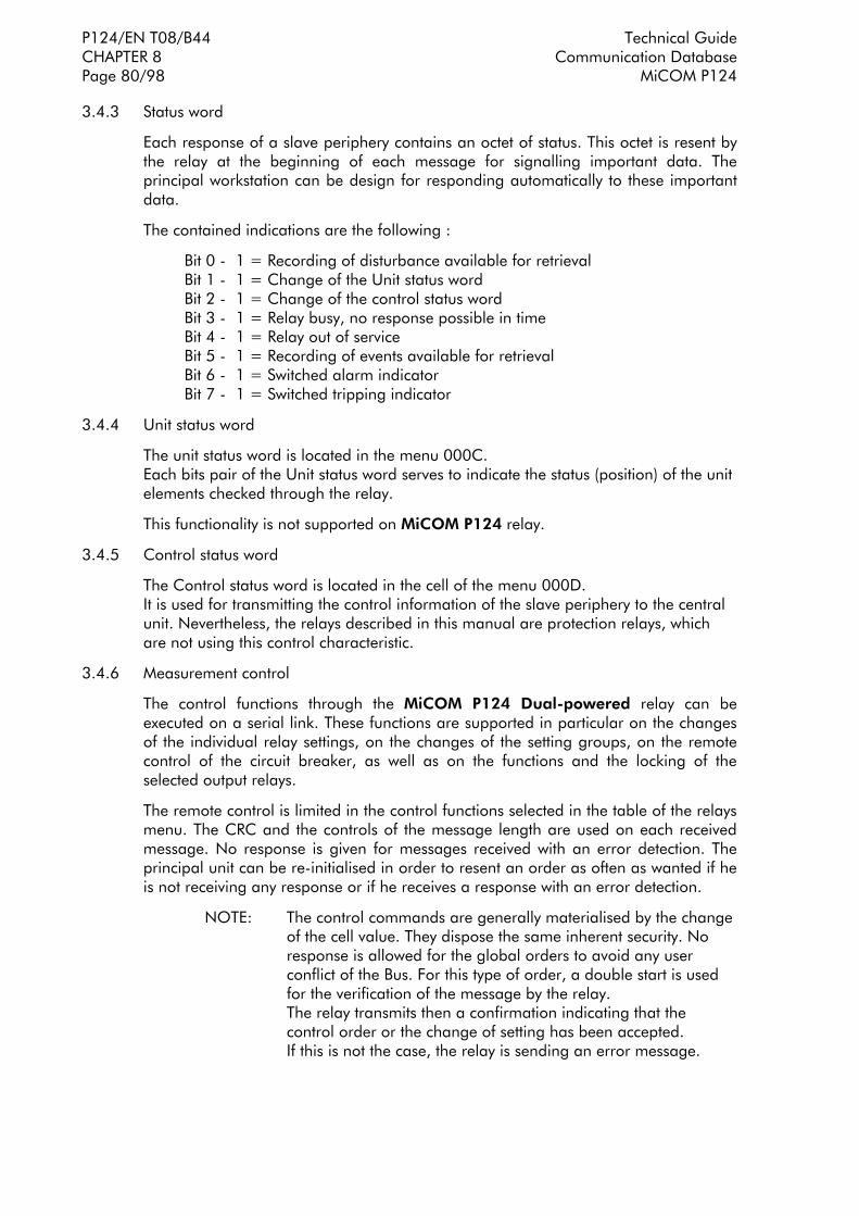
P124/EN T08/B44 Technical Guide CHAPTER 8 Communication Database Page 80/98 MiCOM P124
3.4.3 Status word
Each response of a slave periphery contains an octet of status. This octet is resent by the relay at the beginning of each message for signalling important data. The principal workstation can be design for responding automatically to these important data.
The contained indications are the following :
Bit 0 - 1 = Recording of disturbance available for retrieval Bit 1 - 1 = Change of the Unit status word Bit 2 - 1 = Change of the control status word Bit 3 - 1 = Relay busy, no response possible in time Bit 4 - 1 = Relay out of service Bit 5 - 1 = Recording of events available for retrieval Bit 6 - 1 = Switched alarm indicator Bit 7 - 1 = Switched tripping indicator
3.4.4 Unit status word
The unit status word is located in the menu 000C. Each bits pair of the Unit status word serves to indicate the status (position) of the unit elements checked through the relay.
This functionality is not supported on MiCOM P124 relay.
3.4.5 Control status word
The Control status word is located in the cell of the menu 000D. It is used for transmitting the control information of the slave periphery to the central unit. Nevertheless, the relays described in this manual are protection relays, which are not using this control characteristic.
3.4.6 Measurement control
The control functions through the MiCOM P124 Dual-powered relay can be executed on a serial link. These functions are supported in particular on the changes of the individual relay settings, on the changes of the setting groups, on the remote control of the circuit breaker, as well as on the functions and the locking of the selected output relays.
The remote control is limited in the control functions selected in the table of the relays menu. The CRC and the controls of the message length are used on each received message. No response is given for messages received with an error detection. The principal unit can be re-initialised in order to resent an order as often as wanted if he is not receiving any response or if he receives a response with an error detection.
NOTE: The control commands are generally materialised by the change of the cell value. They dispose the same inherent security. No response is allowed for the global orders to avoid any user conflict of the Bus. For this type of order, a double start is used for the verification of the message by the relay. The relay transmits then a confirmation indicating that the control order or the change of setting has been accepted. If this is not the case, the relay is sending an error message.

Technical Guide P124/EN T08/B44 Communication Database CHAPTER 8 MiCOM P124 Page 81/98
3.4.7 Change of remote measurements
The relay is only responding to the orders of a setting change through the serial port if the SD0 link = 1 is selected. The selection of the SD0 link = 1 is blocking all the changes of remote setting with the exception of the SC logical links and the password capture. When the SD0 link = 0 is selected, the remote setting are protected by the password.
For changing the remote links, the password has to be first remote captured and the SD and SD0 function links have to be settled on 1.
3.5 Event extraction
Events can be extracted either automatically or manually . For automatic extraction all events are extracted in sequential order using the standard Courier mechanism, this includes fault. The manual approach allows the user to select events, faults at random from the stored records.
3.5.1 Automatic event extraction
This method is intended for continuous extraction of event and fault information as it is produced via the rear port.
When new event information is created the Event bit is set within the Status byte, this indicates to the Master device that event information is available. The oldest, unextracted event can be extracted from the relay using the Send Event command. The relay will respond with the event data, which will be either a Courier Type 0 or Type 3 event. The Type 3 event is used for fault records.
Once an event has been extracted from the relay the Accept Event can be used to confirm that the event has been successfully extracted. If all events have been extracted then the event bit will reset, if there are more events still to be extracted the next event can be accessed using the Send Event command as before.
3.5.2 Event types
Events will be created by the relay under the following circumstances:
• Change of state of output contact
• Change of state of opto input
• Protection element operation
• Alarm condition
• Setting Change
• Fault Record (Type 3 Courier Event)

P124/EN T08/B44 Technical Guide CHAPTER 8 Communication Database Page 82/98 MiCOM P124
3.5.3 Event format
The Send Event command results in the following fields being returned by the relay:
• Cell Reference
• Timestamp
• Cell Text
• Cell Value
The table of the events created by the relay (3.2.2) indicates how the contents of the above fields are interpreted. Fault records will return a Courier Type 3 event which contains the above fields together with two additional fields:
• Event extraction column
• Event number
These events contain additional information which is extracted from the relay using the referenced extraction column. Row 01 of the extraction column contains a setting which allows the fault record to be selected. This setting should be set to the event number value returned within the record, the extended data can be extracted from the relay by uploading the text and data from the column.
3.5.4 Manual record extraction
Column 02 of the database can be used for manual viewing fault records. The contents of this column will depend of the nature of the record selected. It is possible to select directly a fault record.
Fault Record Selection (Row 01) - This cell can be used to directly select a fault record using a value between 0 and 4 to select one of up to five stored fault records (0 will be the most recent fault and 4 will be the oldest). The column will then contain the details of the fault record selected (row 02 to 0A)
It should be noted that if this column is used to extract event information from the relay the number associated with a particular record will change when a new fault occurs.
3.6 Disturbance record extraction
The stored disturbance records within the relay are accessible via the Courier interface.
Select Record Number (Row 01) - This cell can be used to select the record to be extracted. Record 0 will be the oldest unextracted record, older records will be assigned positive values, and negative values will be used for more recent records. To facilitate automatic extraction via the rear port the Disturbance bit of the Status byte is set by the relay whenever there are unextracted disturbance records.
Once a record has been selected, using the above cell, the time and date of the record can be read from cell 02. The disturbance record itself can be extracted using the block transfer mechanism from cell B00B.
As has been stated the rear Courier port can be used to automatically extract disturbance records as they occur. This operates using the standard Courier mechanism defined in Chapter 8 of the Courier User Guide.

Technical Guide P124/EN T08/B44 Communication Database CHAPTER 8 MiCOM P124 Page 83/98
4. IEC60870-5-103 INTERFACE
The IEC60870-5-103 interface is a master/slave interface with the relay as the slave device. This protocol is based on the VDEW communication protocol. The relay conforms to compatibility level 2, compatibility level 3 is not supported.
The following IEC60870-5-103 facilities are supported by this interface:
• Initialisation (Reset)
• Time Synchronisation
• Event Record Extraction
• General Interrogation
• Cyclic Measurements
• General Commands
4.1 Physical connection and link layer
Connection is available for IEC60870-5-103 through the rear RS485 port. It is possible to select both the relay address and baud rate using the front panel interface. Following a change, a reset command is required to re-establish communications.
The parameters of the communication are the following :
• Even Parity
• 8 Data bits
• 1 stop bit
• Data rate 9600 or 19200 bauds
4.2 Initialisation
Whenever the relay has been powered up, or if the communication parameters have been changed a reset command is required to initialise the communications. The relay will respond to either of the two reset commands (Reset CU or Reset FCB), the difference being that the Reset CU will clear any unsent messages in the relay's transmit buffer.
The relay will respond to the reset command with an identification message ASDU 5, the Cause Of Transmission COT of this response will be either Reset CU or Reset FCB depending on the nature of the reset command. The following information will be contained in the data section of this ASDU:
Manufacturer Name: Schneider Electric
The Software Identification Section will contain the first four characters of the relay model number to identify the type of relay, eg P124.
In addition to the above identification message, if the relay has been powered up it will also produce a power up event.

P124/EN T08/B44 Technical Guide CHAPTER 8 Communication Database Page 84/98 MiCOM P124
4.3 Time synchronisation
The relay time and date can be set using the time synchronisation feature of the IEC60870-5-103 protocol. The relay will correct for the transmission delay as specified in IEC60870-5-103. If the time synchronisation message is sent as a send/confirm message then the relay will respond with a confirm. Whether the time synchronisation message is sent as a send confirm or a broadcast (send/no reply) message, a time synchronisation message will be returned as Class 1 data.
4.4 Spontaneous events
The events created by the relay will be passed using the standard function type/information numbers to the IEC60870-5-103 master station. Private codes are not used, thus any events that cannot be passed using the standardised messages will not be sent.
Events are categorised using the following information:
• Common Address
• Function Type
• Information number
Section 4.10 contains a complete listing of all events produced by the relay. The common address is used to differentiate in circumstances where the relay produces more events of a certain type than can be passed using the standardised messages. For example if the relay produces starts and trips for three stages of overcurrent only two stages can be passed using the standardised messages.
Using the different common address for two of the overcurrent stages allows each stage to be indicated. The table in 4.10 of the present chapter shows the common address as an offset value. The common address offset will be added to the station address in order to pass these events.
4.5 General interrogation
The GI request can be used to read the status of the relay, the function numbers, information numbers and common address offsets that will be returned during the GI cycle are indicated in 4.10.
4.6 Cyclic measurements
The relay will produce measured values using ASDU 9 on a cyclical basis, this can be read from the relay using a Class 2 poll (note ADSU 3 is not used).
It should be noted that the measurands transmitted by the relay are sent as a proportion of either 1.2 or 2.4 times the rated value of the analogue value. The selection of either 1.2 or 2.4 for a particular value is indicated in 4.10.
4.7 Commands
A list of the supported commands is contained in 4.10. The relay will respond to other commands with an ASDU 1, with a cause of transmission (COT) of negative acknowledgement of a command.
4.8 Disturbance records
The disturbance records stored by the relay cannot be extracted using the mechanism defined in the IEC60870-5-103 standard. The relay maintains compatibility with the VDEW control system by transmitting an ASDU 23 with no disturbance records at the start of every GI cycle.

Technical Guide P124/EN T08/B44 Communication Database CHAPTER 8 MiCOM P124 Page 85/98
4.9 Blocking of monitor direction
The relay does not support a facility to block messages in the Monitor direction.
4.10 List of events produced by the relay
Two kinds of ASDU can be generated for the events : ASDU 1 (time-tagged message) or ASDU2 (Time-tagged message with relative time)
The list of events is the following with the associated values : INFORMATION NUMBER, TYPE OF ASDU ,CAUSE OF TRANSMISSION and COMMON ADDRESS OF ASDU
Status indication in monitor direction :
− Auto-recloser active : INF <16>; TYP <1>;COT<1>, <ADDRESS> ↓↑
− LED reset : INF <19>; TYP <1>; COT<1>, <ADDRESS> − Characteristic 1 : INF <23>; TYP <1>; COT<1>, <ADDRESS> ↓↑
− Characteristic 2 : INF <24>; TYP <1>; COT<1>, <ADDRESS> ↓↑
− Logic input 1 : INF <27>; TYP <1>; COT<1>, <ADDRESS> ↓↑
− Logic input 2 : INF <28>; TYP <1>; COT<1>, <ADDRESS> ↓↑
− Logic input 3 : INF <29>; TYP <1>; COT<1>, <ADDRESS> ↓↑
− Logic input 4 : INF <30>; TYP <1>; COT<1>, <ADDRESS> ↓↑
− Logic input 5 : INF <27>; TYP <1>; COT<1>, <ADDRESS+1> ↓↑
Supervision indications in monitor direction :
− Trip circuit supervision : INF <36>; TYP <1>; COT<1>, <ADDRESS> ↓↑
Fault indications in monitor direction :
− Start/pick-up N : INF <67>; TYP <2>; COT<1>, <ADDRESS> ↓↑
− General TRIP : INF <68>; TYP <2>; COT<1>,<ADDRESS>
− TRIP L1 : INF <69>; TYP <2>; COT<1>,<ADDRESS>
− TRIP L2 : INF <70>; TYP <2>; COT<1>, <ADDRESS>
− TRIP L3 : INF <71>; TYP <2>; COT<1>, <ADDRESS> − General start : INF <84>; TYP <2>; COT<1>, <ADDRESS> ↓↑
− Breaker failure : INF <85>; TYP <2>; COT<1>, <ADDRESS>
− TRIP I> : INF <90>; TYP <2>; COT<1>, <ADDRESS>
− TRIP I>> : INF <91>; TYP <2>; COT<1>, <ADDRESS>
− TRIP I>>> : INF <90>; TYP <2>; COT<1>, <ADDRESS+1>
− TRIP IN> : INF <92>; TYP <2>; COT<1>, <ADDRESS>
− TRIP IN>>: INF <93>; TYP <2>; COT<1>, <ADDRESS>
− TRIP IN>>> : INF <92>; TYP <2>; COT<1>, <ADDRESS+1>
− Auto-reclosure indications in monitor direction
− CB 'on' by AR : INF <128>; TYP <1>; COT<1>, <ADDRESS>
− CB 'on' by long time AR : INF <129>; TYP <1>; COT<1>,<ADDRESS> − AR blocked : INF <130>; TYP <1>; COT<1>, <ADDRESS> ↓↑
NOTA : The italics events are only valid for the MiCOM P124. The double arrow ↓↑ means the event is generated on event occurrence and another is generated on event disappearance.
• List of data contained in General Interrogation

P124/EN T08/B44 Technical Guide CHAPTER 8 Communication Database Page 86/98 MiCOM P124
Status indication in monitor direction :
− Auto-recloser active : INF <16>; TYP <1>; COT <9>, <ADDRESS>
− Characteristic 1 : INF <23>; TYP <1>; COT <9>, <ADDRESS>
− Characteristic 2 : INF <24>; TYP <1>; COT <9>, <ADDRESS>
− Auxiliary input 1 : INF <27>; TYP <1>; COT <9>, <ADDRESS>
− Auxiliary input 2 : INF <28>; TYP <1>; COT <9>, <ADDRESS>
− Auxiliary input 3 : INF <29>; TYP <1>; COT <9>, <ADDRESS>
− Auxiliary input 4 : INF <30>; TYP <1>; COT <9>, <ADDRESS>
− Auxiliary input 5 : INF <27>; TYP <1>; COT <9>, <ADDRESS+1>
Supervision indications in monitor direction :
− Trip circuit supervision : INF <36>; TYP <1>; COT <9>, <ADDRESS>
Fault indications in monitor direction :
− Start/pick-up N : INF <67>; TYP <2>; COT <9>,<ADDRESS>
− General start : INF <84>; TYP <2>; COT <9>, <ADDRESS>
Auto-reclosure indications in monitor direction
− AR blocked : INF <130>; TYP <1>; COT <9>, <ADDRESS>
• Cyclic measurements
The selection of either 1.2 or 2.4 for a particular value is the following :
For the current value Ia, Ib and Ic the rate is equal to 2.4
For the frequency the rate is equal to 1.2
The other fields of ASDU 9 are not updated.
• List of the supported commands
⇒ Autorecloser ON/OFF only on MiCOM P123 : INF<16>, TYP<20>, COT <20>
⇒ LED reset . This command corresponds to the acknowledgment of all alarms by the front plate on MiCOM P12x products : INF<19>, TYP<20>, COT <20>
⇒ Charcateristic 1 : INF<23>, TYP<20>, COT <20>
⇒ Characteristic 2 : INF<23>, TYP<20>, COT <20>

Technical Guide P124/EN T08/B44 Communication Database CHAPTER 8 MiCOM P124 Page 87/98
5. DNP 3.0 CONFIGURATION/INTEROPERABILITY GUIDE
5.1 Introduction
The purpose of this document is to describe the specific implementation of the Distributed Network Protocol (DNP) 3.0 within P12x.
P12x uses the Triangle MicroWorks, Inc. DNP 3.0 Slave Source Code Library Version 2.18.
This document, in conjunction with the DNP 3.0 Basic 4 Document Set, and the DNP Subset Definitions Document, provides complete information on how to communicate with P12x via the DNP 3.0 protocol.
This implementation of DNP 3.0 is fully compliant with DNP 3.0 Subset Definition Level 2, contains many Subset Level 3 features, and contains some functionality even beyond Subset Level 3.
5.2 DNP V3.00 device profile
The following table provides a irDevice Profile DocumentlK in the standard format defined in the DNP 3.0 Subset Definitions Document. While it is referred to in the DNP 3.0 Subset Definitions as a isDocument,l. it is only a component of a total interoperability guide. This table, in combination with the following should provide a complete interoperability/configuration guide for P12x :
• the Implementation Table provided in Section 0 (beginning on page 66),
• the Point List Tables provided in Section 5.4 (beginning on page 69),
DNP V3.00
DEVICE PROFILE DOCUMENT
(Also see the Implementation Table in Section 0, beginning on page 66.)
Vendor Name: Schneider Electric
Device Name: SERIAL 20 Platform using the Triangle MicroWorks, Inc. DNP 3.0 Slave Source
Code Library, Version 2.18.
Highest DNP Level Supported:
For Requests: Level 2
For Responses: Level 2
Device Function:
Master
Slave
Notable objects, functions, and/or qualifiers supported in addition to the Highest DNP Levels Supported (the complete list is described in the attached table):
For static (non-change-event) object requests, request qualifier codes 00 and 01 (start-stop), 07 and 08 (limited quantity), and 17 and 28 (index) are supported in addition to request qualifier code 06 (no range – or all points).
Static object requests received with qualifiers 00, 01, 06, 07, or 08, will be responded with qualifiers 00 or 01. Static object requests received with qualifiers 17 or 28 will be responded with qualifiers 17 or 28.
For change-event object requests, qualifiers 17 or 28 are always responded.
16-bit and 32-bit Analog Change Events with Time may be requested.
The read function code for Object 50 (Time and Date), variation 1, is supported.
Maximum Data Link Frame Size (octets):
Transmitted: 292
Received 292
Maximum Application Fragment Size (octets):
Transmitted: 2048
Received: 2048

P124/EN T08/B44 Technical Guide CHAPTER 8 Communication Database Page 88/98 MiCOM P124
DNP V3.00
DEVICE PROFILE DOCUMENT
(Also see the Implementation Table in Section 0, beginning on page 66.)
Maximum Data Link Re-tries: ! None " Fixed at 2 ! Configurable
Maximum Application Layer Re-tries:
" None ! Configurable
Requires Data Link Layer Confirmation: " Never Always Sometimes Configurable
Requires Application Layer Confirmation: Never Always " When reporting Event Data " When sending multi-fragment responses Sometimes Configurable
Timeouts while waiting for: Data Link Confirm: None " Fixed at 100 ms Variable Configurable Complete Appl. Fragment: " None Fixed at ____ Variable Configurable Application Confirm: None " Fixed at 1s Variable Configurable Complete Appl. Response: " None Fixed at ____ Variable Configurable
Others: Binary input change scanning period: 5ms Analog input change scanning period: 1s
Sends/Executes Control Operations: WRITE Binary Outputs " Never Always Sometimes Configurable SELECT/OPERATE Never " Always Sometimes Configurable DIRECT OPERATE Never " Always Sometimes Configurable DIRECT OPERATE NO ACK Never " Always Sometimes Configurable
Count > 1 " Never Always Sometimes Configurable Pulse On Never " Always Sometimes Configurable Pulse Off " Never Always Sometimes Configurable Latch On " Never Always Sometimes Configurable Latch Off " Never Always Sometimes Configurable
Queue " Never Always Sometimes Configurable Clear Queue " Never Always Sometimes Configurable
Reports Binary Input Change Events when no specific variation requested:
Never " Only time-tagged Configurable
Reports time-tagged Binary Input Change Events when no specific variation requested:
Never " Binary Input Change With Time Binary Input Change With Relative Time Configurable (attach explanation)

Technical Guide P124/EN T08/B44 Communication Database CHAPTER 8 MiCOM P124 Page 89/98
DNP V3.00
DEVICE PROFILE DOCUMENT
(Also see the Implementation Table in Section 0, beginning on page 66.)
Sends Unsolicited Responses:
" Never Configurable Only certain objects Sometimes (attach explanation) ENABLE/DISABLE UNSOLICITED Function codes supported
Sends Static Data in Unsolicited Responses:
" Never When Device Restarts When Status Flags Change
No other options are permitted.
Default Counter Object/Variation:
No Counters Reported Configurable " Default Object: 20 Default Variation: 5 Point-by-point list attached
Counters Roll Over at:
No Counters Reported Configurable (attach explanation) " 16 Bits " 32 Bits Other Value: _____ " Point-by-point list attached
Sends Multi-Fragment Responses:
" Yes No

P124/EN T08/B44 Technical Guide CHAPTER 8 Communication Database Page 90/98 MiCOM P124
5.3 Implementation table
The following table identifies the variations, function codes, and qualifiers supported by the P12x in both request messages and in response messages.
For static (non-change-event) objects, requests sent with qualifiers 00, 01, 06, 07, or 08, will be responded with qualifiers 00 or 01. Static object requests sent with qualifiers 17 or 28 will be responded with qualifiers 17 or 28. For change-event objects, qualifiers 17 or 28 are always responded.
In the table below text shaded as Subset Level 3 indicates Subset Level 3 functionality (beyond Subset Level 2), and text shaded as beyond Subset Level 3 indicates functionality beyond Subset Level 3.
OBJECT REQUEST
(Library will parse) RESPONSE (Library will
respond with)
Object Number
Variation Number
Description Function Codes (dec)
Qualifier Codes (hex)
Function Codes (dec)
Qualifier Codes (hex)
1 0 Binary Input (Variation 0 is used to request default variation)
1 (read) 00, 01 (start-stop) 06 (no range, or all) 07, 08 (limited qty) 17, 28 (index)
1 1 (default
see note 1)
Binary Input 1 (read) 22 00, 01 (start-stop) 06 (no range, or all) 07, 08 (limited qty) 17, 28 (index)
129 (response) 00, 01 (start-stop) 17, 28 (index see note 2)
2 0 Binary Input Change (Variation 0 is used to request default variation)
1 (read) 06 (no range, or all) 07, 08 (limited qty)
2 1 (default see note 1 for P120 -
P121)
Binary Input Change without Time
1 (read) 06 (no range, or all) 07, 08 (limited qty)
129 (response) 17, 28 (index)
2 2 (default
see note 1)
Binary Input Change with Time 1 (read) 06 (no range, or all) 07, 08 (limited qty)
129 (response) 17, 28 (index)
10 0 Binary Output Status (Variation 0 is used to request default variation)
1 (read) 00, 01 (start-stop) 06 (no range, or all) 07, 08 (limited qty) 17, 28 (index)
10 2 (default
see note 1)
Binary Output Status 1 (read) 00, 01 (start-stop) 06 (no range, or all) 07, 08 (limited qty) 17, 28 (index)
129 (response) 00, 01 (start-stop) 17, 28 (index see note 2)
12 1 Control Relay Output Block 3 (select) 4 (operate) 5 (direct op) 6 (dir. op, noack)
00, 01 (start-stop) 0 7, 08 (limited qty) 17, 28 (index)
129 (response) echo of request
20 0 Binary Counter (Variation 0 is used to request default variation)
1 (read) 7 (freeze) 8 (freeze noack) 9 (freeze clear) 10 (frz. cl. noack)
00, 01 (start-stop) 06 (no range, or all) 07, 08 (limited qty) 17, 28 (index)
20 1 32-Bit Binary Counter 1 (read) 7 (freeze) 8 (freeze noack) 9 (freeze clear) 10 (frz. cl. noack)
00, 01 (start-stop) 06 (no range, or all) 07, 08 (limited qty) 17, 28 (index)
129 (response) 00, 01 (start-stop) 17, 28 (index see note 2)
20 2 16-Bit Binary Counter 1 (read) 7 (freeze) 8 (freeze noack) 9 (freeze clear) 10 (frz. cl. noack)
00, 01 (start-stop) 06 (no range, or all) 07, 08 (limited qty) 17, 28 (index)
129 (response) 00, 01 (start-stop) 17, 28 (index see note 2)
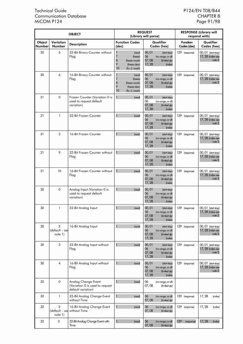
Technical Guide P124/EN T08/B44 Communication Database CHAPTER 8 MiCOM P124 Page 91/98
OBJECT REQUEST
(Library will parse) RESPONSE (Library will
respond with)
Object Number
Variation Number
Description Function Codes (dec)
Qualifier Codes (hex)
Function Codes (dec)
Qualifier Codes (hex)
20 5 32-Bit Binary Counter without Flag
1 (read) 7 (freeze) 8 (freeze noack) 9 (freeze clear) 10 (frz. cl. noack)
00, 01 (start-stop) 06 (no range, or all) 07, 08 (limited qty) 17, 28 (index)
129 (response) 00, 01 (start-stop) 17, 28 (indexsee note 2)
20 6 16-Bit Binary Counter without Flag
1 (read) 7 (freeze) 8 (freeze noack) 9 (freeze clear) 10 (frz. cl. noack)
00, 01 (start-stop) 06 (no range, or all) 07, 08 (limited qty) 17, 28 (index)
129 (response) 00, 01 (start-stop) 17, 28 (indexsee note 2)
21 0 Frozen Counter (Variation 0 is used to request default variation)
1 (read) 00, 01 (start-stop) 06 (no range, or all) 07, 08 (limited qty) 17, 28 (index)
21 1 32-Bit Frozen Counter 1 (read) 00, 01 (start-stop) 06 (no range, or all) 07, 08 (limited qty) 17, 28 (index)
129 (response) 00, 01 (start-stop) 17, 28 (indexsee note 2)
21 2 16-Bit Frozen Counter 1 (read) 00, 01 (start-stop) 06 (no range, or all) 07, 08 (limited qty) 17, 28 (index)
129 (response) 00, 01 (start-stop) 17, 28 (indexsee note 2)
21 9 32-Bit Frozen Counter without Flag
1 (read) 00, 01 (start-stop) 06 (no range, or all) 07, 08 (limited qty) 17, 28 (index)
129 (response) 00, 01 (start-stop) 17, 28 (indexsee note 2)
21 10 16-Bit Frozen Counter without Flag
1 (read) 00, 01 (start-stop) 06 (no range, or all) 07, 08 (limited qty) 17, 28 (index)
129 (response) 00, 01 (start-stop) 17, 28 (indexsee note 2)
30 0 Analog Input (Variation 0 is used to request default variation)
1 (read) 00, 01 (start-stop) 06 (no range, or all) 07, 08 (limited qty) 17, 28 (index)
30 1 32-Bit Analog Input 1 (read) 00, 01 (start-stop) 06 (no range, or all) 07, 08 (limited qty) 17, 28 (index)
129 (response) 00, 01 (start-stop) 17, 28 (indexsee note 2)
30 2 (default see
note 1)
16-Bit Analog Input 1 (read) 00, 01 (start-stop) 06 (no range, or all) 07, 08 (limited qty) 17, 28 (index)
129 (response) 00, 01 (start-stop) 17, 28 (indexsee note 2)
30 3 32-Bit Analog Input without Flag
1 (read) 00, 01 (start-stop) 06 (no range, or all) 07, 08 (limited qty) 17, 28 (index)
129 (response) 00, 01 (start-stop) 17, 28 (indexsee note 2)
30 4 16-Bit Analog Input without Flag
1 (read) 00, 01 (start-stop) 06 (no range, or all) 07, 08 (limited qty) 17, 28 (index)
129 (response) 00, 01 (start-stop) 17, 28 (indexsee note 2)
32 0 Analog Change Event (Variation 0 is used to request default variation)
1 (read) 06 (no range, or all) 07, 08 (limited qty)
32 1 32-Bit Analog Change Event without Time
1 (read) 06 (no range, or all) 07, 08 (limited qty)
129 (response) 17, 28 (index)
32 2 (default see
note 1)
16-Bit Analog Change Event without Time
1 (read) 06 (no range, or all) 07, 08 (limited qty)
129 (response) 17, 28 (index)
32 3 32-Bit Analog Change Event with Time
1 (read) 06 (no range, or all) 07, 08 (limited qty)
129 (response) 17, 28 (index)

P124/EN T08/B44 Technical Guide CHAPTER 8 Communication Database Page 92/98 MiCOM P124
OBJECT REQUEST
(Library will parse) RESPONSE (Library will
respond with)
Object Number
Variation Number
Description Function Codes (dec)
Qualifier Codes (hex)
Function Codes (dec)
Qualifier Codes (hex)
32 4 16-Bit Analog Change Event with Time
1 (read) 06 (no range, or all) 07, 08 (limited qty)
129 (response) 17, 28 (index)
50 0 Time and Date 1 (read) 00, 01 (start-stop) 06 (no range, or all) 07, 08 (limited qty) 17, 28 (index)
129 (response) 00, 01 (start-stop) 17, 28 (index see note 2)
50 1 default see
note 1)
Time and Date 1 (read) 2 (write)
00, 01 (start-stop) 06 (no range, or all) 07, 08 (limited qty) 17, 28 (index)
129 (response) 00, 01 (start-stop) 17, 28 (index see note 2)
52 2 Time Delay Fine 129 (response) 07 (limited qty) (qty = 1)
60 0 Class 0, 1, 2, and 3 Data 1 (read) 06 (no range, or all)
60 1 Class 0 Data 1 (read)
06 (no range, or all) 129 17,28
60 2 Class 1 Data 1 (read)
06 (no range, or all) 07, 08 (limited qty)
129 17,28
60 3 Class 2 Data 1 (read)
06 (no range, or all) 07, 08 (limited qty)
129 17,28
60 4 Class 3 Data 1 (read)
06 (no range, or all) 07, 08 (limited qty)
129 17,28
80 1 Internal Indications 2 (write) 00 (start-stop) (index must =7)
No Object (function code only) See Note 3 13 (cold restart)
No Object (function code only) 14 (warm restart)
No Object (function code only) 23 (delay meas.)
NOTE 1: A Default variation refers to the variation responded when variation 0 is requested and/or in class 0, 1, 2, or 3 scans.
NOTE 2: For static (non-change-event) objects, qualifiers 17 or 28 are only responded when a request is sent with qualifiers 17 or 28, respectively. Otherwise, static object requests sent with qualifiers 00, 01, 06, 07, or 08, will be responded with qualifiers 00 or 01. (For change-event objects, qualifiers 17 or 28 are always responded.)
NOTE 3: For P12x, a cold restart is implemented as a warm restart the executable is not restarted, but the DNP process is restarted.

Technical Guide P124/EN T08/B44 Communication Database CHAPTER 8 MiCOM P124 Page 93/98
5.4 Point List
The tables in the following sections identify all the individual data points provided by this implementation of DNP 3.0. P12x uses the database protection.
5.4.1 Binary Input Points
Every Binary Input Status points are included in class 0 polls, because they are included in one of classes 1, 2 or 3.
Binary Input Points
Static (Steady-State) Object Number: 1
Change Event Object Number: 2
Request Function Codes supported: 1 (read)
Static Variation reported when variation 0 requested: 1 (Binary Input without status)
Change Event Variation reported when variation 0 requested: 2 (Binary Input Change with Time)
Point Index
Name/Description init val. Change Event Class
(1, 2, 3 or none)
0 Output relay 1 (trip) 0 1
1 Output r elay 2 0 2
2 Output r elay 3 0 2
3 Output r elay 4 0 2
4 Output relay 0 ( watch dog) 0 2
5 Output r elay 5 0 2
6 Output r elay 6 0 2
9 Opto isolator 1 0 2
10 Opto isolator 2 0 2
11 Opto isolator 3 0 2
12 Opto isolator 4 0 2
13 Opto isolator 5 0 2
14 Phase overcurrent stage 1 start 0 1
15 Phase overcurrent stage 1 trip 0 1
16 Phase overcurrent stage 2 start 0 1
17 Phase overcurrent stage 2 trip 0 1
18 Phase overcurrent stage 3 start 0 1
19 Phase overcurrent stage 3 trip 0 1
20 Earth overcurrent stage 1 start 0 1
21 Earth overcurrent stage 1 trip 0 1
22 Earth overcurrent stage 2 start 0 1
23 Earth overcurrent stage 2 trip 0 1
24 Earth overcurrent stage 3 start 0 1
25 Earth overcurrent stage 3 trip 0 1
26 tI< 0 1
27 thermal start 0 1
28 thermal trip 0 1
29 taux1 0 1

P124/EN T08/B44 Technical Guide CHAPTER 8 Communication Database Page 94/98 MiCOM P124
Binary Input Points
Static (Steady-State) Object Number: 1
Change Event Object Number: 2
Request Function Codes supported: 1 (read)
Static Variation reported when variation 0 requested: 1 (Binary Input without status)
Change Event Variation reported when variation 0 requested: 2 (Binary Input Change with Time)
Point Index
Name/Description init val. Change Event Class
(1, 2, 3 or none)
30 taux2 0 1
31 broken conductor 0 1
32 cb failure 0 1
33 I2> start 0 1
34 tI2> trip 0 1
35 number of cb operation 0 1
36 Cb operation time alarm 0 1
37 sa2n 0 1
38 trip circuit alarm 0 1
39 cb close time alarm 0 1
40 Recloser locked 0 1
41 Recloser success 0 1
42 Recloser running 0 1
43 Logic selectivity 1 0 1
44 Logic selectivity 2 0 1
45 Blocking logic 1 0 1
46 Blocking logic 2 0 1
47 52a 0 1
48 52b 0 1
49 CB external failure 0 1
50 Cold load pick up 0 1
51 Unlatch by logic input 0 1
52 Unlatch RL1 by remote command 0 1
53 Close remote command 0 1
54 Trip remote command 0 1
55 Reset thermal state by communication 0 1
56 Maintenance mode 0 1
57 Major hardware alarm 0 1
58 Minor hardware alarm 0 1
59 Phase overcurrent stage 1 trip alarm (latched) 0 3
60 Phase overcurrent stage 2 trip alarm (latched) 0 3
61 Phase overcurrent stage 3 trip alarm (latched) 0 3
62 Earth overcurrent stage 1 trip alarm (latched) 0 3
63 Earth overcurrent stage 2 trip alarm (latched) 0 3

Technical Guide P124/EN T08/B44 Communication Database CHAPTER 8 MiCOM P124 Page 95/98
Binary Input Points
Static (Steady-State) Object Number: 1
Change Event Object Number: 2
Request Function Codes supported: 1 (read)
Static Variation reported when variation 0 requested: 1 (Binary Input without status)
Change Event Variation reported when variation 0 requested: 2 (Binary Input Change with Time)
Point Index
Name/Description init val. Change Event Class
(1, 2, 3 or none)
64 Earth overcurrent stage 3 trip alarm (latched) 0 3
65 tI< alarm (latched) 0 3
66 thermal start alarm (latched) 0 3
67 thermal trip alarm (latched) 0 3
68 taux1 alarm (latched) 0 3
69 taux2 alarm (latched) 0 3
70 broken conductor alarm (latched) 0 3
71 cb failure alarm (latched) 0 3
72 tI2> alarm (latched) 0 3
73 Cb operation time alarm(latched) 0 3
74 number of cb operation (latched) 0 3
75 sa2n alarm (latched) 0 3
76 trip circuit alarm(latched) 0 3
77 cb close time alarm ( latched) 0 3
78 Conflict recloser 0 3

P124/EN T08/B44 Technical Guide CHAPTER 8 Communication Database Page 96/98 MiCOM P124
5.4.2 Binary Output Status Points and Control Relay Output Blocks
The following table lists both the Binary Output Status Points (Object 10) and the Control Relay Output Blocks (Object 12).
Binary Output Status points are not included in class 0 polls.
Binary Output Status Points
Object Number: 10
Request Function Codes supported: 1 (read)
Default Variation reported when variation 0 requested: 2 (Binary Output Status)
Control Relay Output Blocks
Object Number: 12
Request Function Codes supported: 3 (select), 4 (operate), 5 (direct operate), 6 (direct operate, noack)
Point Index
Name/Description Initial Status
Value
Supported Control Relay Output Block
Fields
0 Unlatch of the relays 0 Pulse On
1 First alarm acknowledge 0 Pulse On
2 All alarm acknowledge 0 Pulse On
3 Trip c ommand 0 Pulse O n
4 Close command 0 Pulse On
5 Change of setting group 0 Pulse On
6 Thermal state reset 0 Pulse On
7 Peak and average value reset 0 Pulse On
8 RAM hardware alarm acknowledge 0 Pulse On
9 Reclose counter reset 0 Pulse On

Technical Guide P124/EN T08/B44 Communication Database CHAPTER 8 MiCOM P124 Page 97/98
5.4.3 Counters
The following table lists both Binary Counters (Object 20) and Frozen Counters (Object 21). When a freeze function is performed on a Binary Counter point, the frozen value is available in the corresponding Frozen Counter point.
Binary Counters and Frozen Counters are not included in class 0 polls.
P120 and P121 do not support binary Counters and Frozen Counters.
Binary Counters
Static (Steady-State) Object Number: 20 Change Event Object Number: not supported Request Function Codes supported: 1 (read), 7 (freeze), 8 (freeze noack) 9 (freeze and clear), 10 (freeze and clear, noack) Static Variation reported when variation 0 requested: 5 (32-Bit Binary Counter without Flag Change Event Variation reported when variation 0 requested: none-not supported
Frozen Counters
Static (Steady-State) Object Number: 21 Change Event Object Number: not supported Request Function Codes supported: 1 (read) Static Variation reported when variation 0 requested: 9 (32-Bit Frozen Binary without Flag) Change Event Variation reported when variation 0 requested: none-not supported
Point Index
Name/Description Data type
0 Max I a R ms D1
1 Max I b R ms D1
2 Max I c R ms D1
3 Average I a R ms D1
4 Average I b R ms D1
5 Average I c R ms D1
6 CB operations D2
7 Σ Amps (n) Ia D3
8 Σ Amps (n) Ib D3
9 Σ Amps (n) Ic D3
10 total number of reclosing shots D2
11 cycle 1 number D2
12 cycle 2 number D2
13 cycle 3 number D2
14 cycle 4 number D2
15 definitive trip number D2
16 close command number D2

P124/EN T08/B44 Technical Guide CHAPTER 8 Communication Database Page 98/98 MiCOM P124
5.4.4 Analog Inputs
The following table lists Analog Inputs (Object 30). It is important to note that 16-bit and 32-bit variations of Analog Inputs, Analog Output Control Blocks, and Analog Output Statuses are transmitted through DNP as signed numbers. Even for analog input points that are not valid as negative values, the maximum positive representation is 32767. For each point, the ihScaling and Unitsli column indicates the value of a transmitted 32767. This also implies the value of a transmitted 32767. The entry in the column does not imply a valid value for the point.
Always indicating the representation of 32767 in the tables below is a consistent method for representing scale, applicable to all scaling possibilities.
The ihDefault Deadband,ln and the ihDefault Change Event Assigned Classl columns are used to represent the absolute amount by which the point must change before an analog change event will be generated, and once generated in which class poll (1, 2, 3) will the change event be reported. Only the default values for these columns are documented here because the values may change in operation due to either local (user-interface) or remote (through DNP) control.
Every Analog Inputs points are included in class 0 polls, because they are included in one of classes 1, 2 or 3.
Analog Inputs Static (Steady-State) Object Number: 30 Change Event Object Number: 32 Request Function Codes supported: 1 (read) Static Variation reported when variation 0 requested: 2 (16-Bit Analog Input) Change Event Variation reported when variation 0 requested: 2 (Analog Change Event w/o Time) Change Event Scan Rate: The scan rate for analog input change events is fixed at 1s
Point Index Name/Description
Initial Value
Scaling and Units (representation of
32767 see above) Valid Range
Change Event Dead-band
Initial Change Event Class (1, 2, 3 or
none)
0 active group 1 32767 1 à 2 1 1
1 module IA 0 40 In 0 to 40 In 0.1 In 2
2 module IB 0 40 In 0 to 40 In 0.1 In 2
3 module IC 0 40 In 0 to 40 In 0.1 In 2
4 module IN 0 40 I0n 0 to 40 I0n 0.02 In 2
5 rms IA 0A 327.67A 0 to 40000000 A/100
10% 2
6 rms IB 0A 327.67A 0 to 40000000 A/100
10% 2
7 rms IC 0A 327.67A 0 to 40000000 A/100
10% 2
8 rms IN 0A 327.67A 0 to 40000000 A/100
10% 2
9 thermal state 0% 32767% 0 to 65535 10 2
10 frequency 0 327,67 Hz 45Hz to 65 Hz and 99.99Hz ==
ERROR
1Hz 2
11 module I2 0 40 In 0 to 40 In 0.1 In 2
12 module I1 0 40 In 0 to 40 In 0.1 In 2
13 trip time 0 327.67s 0 to 10.00s 10 ms 2
14 close time 0 327.67s 0 to 10.00s 10 ms 2

Technical Guide P124/EN TA1/B44 MiCOM P124
APPENDIX 1 Connection diagrams


Technical Guide P124/EN TA1/B44 Connection Diagrams APPENDIX 1 MICOM P124 Page 1/6
MiCOM P124 Self-powered model Typical application diagram
P12
4S
elt-
po
wer
ed m
od
el
3 p
has
e C
Ts
con
nec
tio
nC
B
A
3537 36 44 42 40 39+
41-
Wat
chd
og
Tri
p o
utp
ut
for
CB
co
il
Tri
p o
utp
ut
for
stri
ker
Cas
e ea
rth
con
nec
tio
n
No
tes
:(1
)
(2)
(a)
CT
co
nn
ecti
on
s ar
e ty
pic
al o
nly
CT
sh
ort
ing
lin
ks m
od
e b
efo
re (
b)
and
(c)
dis
con
nec
t
(b)
Sh
ort
term
inal
s b
reak
bef
ore
(c)
(c)
Lo
ng
term
inal
s
(d)
Pin
s te
rmin
als
(p c
b t
ype)
RL
0
RL
1
Ph
ase
rota
tio
n
Alt
ern
ativ
e :
3 p
has
e C
Ts
+ co
re b
alan
ced
CT
co
nn
ecti
on
A B C
P2
P1
S2
S1
49 501
A o
u 5A
1 A
ou
5 A
1 A
ou
5 A
S2
S1
-
-
51 52 53 54 56 55 48 47
1 A
ou
5A
1 A
ou
5A
A B C
P2
P1
S2
S1
49 501
A o
u 5A
1 A
ou
5 A
-
51 52 53 54 56 55
1 A
ou
5A
1 A
ou
5A
48 47
30 32 34 36 38 40 42 44 46 48 50 52 54 56
29 31 33 35 37 39 41 43 45 47 49 51 53 55
Mo
du
le t
erm
inal
blo
ckvi
ewed
fro
m r
ear
Alt
ern
ativ
e :
2 p
has
e C
Ts
+ co
re b
alan
ced
CT
co
nn
ecti
on
A B C
P2
P1
S2
S1
49 501
A o
u 5A
1 A
ou
5 A
S2
S1
-
51 52 53 54 56 55 48 47
1 A
ou
5A
1 A
ou
5A
SCHEME REPRESENTING MiCOM RELAY OFF

P124/EN TA1/B44 Technical Guide APPENDIX 1 Connection Diagrams Page 2/6 MiCOM P124
MiCOM P124 self-powered model Rear connections
In case of Self-powered model, only one 28 connection points Midos connector is used following the diagram below :
29
31
33
35
37
39
41
43
45
47
49
51
53
55
30
32
34
36
38
40
42
44
46
48
50
52
54
56
NC
NC
NC
Common RL0 (Watchdog)
NC
Common RL1 (trip)
RL1 (trip) normally closed contact
RL1 (trip) normally open contact
Reserve, do not use
Common earth current inputfor 3CTs connectionCommun
Phase A
Common Phase B
Common Phase C
Common earth current input(2)
NC
NC
NC
RL0 (WD) normally closed contact
RL0 (WD) normally open contact
Striker output +
Striker output -
Reserved, do not use
Reserve, do not use
Earth current input (1)for 3CTs connection
Phase A (1)
Phase B (1)
Phase C (1)
Earth current input (1)(2)
Rear view, connector 1 :
NC : no connected
(1) the current inputs are 1 or 5A and defined on ordering code
(2) inputs used when it is necessary to power the MiCOM P124 relay via the earth current input.

Technical Guide P124/EN TA1/B44 Connection Diagrams APPENDIX 1 MICOM P124 Page 3/6
MiCOM P124 Dual-powered model Typical application diagram
C
A
3537 36 44 42 40 39+
41-
30 32 34 36 38 40 42 44 46 48 50 52 54 56
29 31 33 35 37 39 41 43 45 47 49 51 53 55
2 4 6 8 10 12 14 16 18 20 22 24 26 28
3 5 7 9 11 13 15 17 19 21 23 25 27
RL
0
RL
1
11-
13+
15-
17+
19-
21+
23-
25+
3334
+-
27-
6 4 2R
L2
12 10 8R
L3
22 20 18R
L4
28 26 24R
L5
5 3 1R
L6
*
29 30
+ -31 32
A B C
P2
P1
S2
S1
49 50
S2
S1
-
-
51 52 53 54 56 55 48 47
A B
BC
P2
P1
S2
S1
49 50
-
51 52 53 541A
or
5A
1A o
r 5A
1A o
r 5A
1A o
r 5A
1A o
r 5A
1A o
r 5A
1A o
r 5A
1A o
r 5A
1A o
r 5A
56 55 48 47 9 +
1
Wat
chd
og
Trip
ou
tpu
tco
nta
ct fo
r C
B c
oil
Pro
gra
mm
eble
ou
tpu
t
Pro
gra
mm
eble
o
utp
ut
Trip
ou
tpu
tfo
r st
rike
r
Cas
e ea
rth
con
nec
tio
n
RS
485
com
mu
nic
atio
n p
ort
P12
4D
ual
-po
wer
edm
od
el
3 p
has
e C
Ts
con
nec
tio
n
(*)
term
inat
ing
res
isto
r fo
r th
e la
stre
lay
to b
e co
nn
ecte
d b
etw
een
30-3
2
Au
xilia
rysu
pp
ly
CT
s sh
ort
ing
lin
ks m
od
eb
efo
re (
b)
and
(c)
dis
con
nec
t
Lo
ng
ter
min
als
Pin
s te
rmin
als
(p c
b t
ype)
CT
co
nn
ecti
on
s ar
e ty
pic
al o
nly
(2)
(1)
(a)
No
tes
:
(b)
(c)
(d)
Pro
gra
mm
eble
o
utp
ut
Pro
gra
mm
eble
o
utp
ut
Pro
gra
mm
eble
o
utp
ut
Mo
du
le t
erm
inal
blo
ckvi
ewed
fro
m r
ear
Alt
ern
ativ
e :
3 p
has
e C
Ts
+ co
re b
alan
ced
CT
co
nn
ecti
on
.
Ph
ase
rota
tio
n
Pro
gra
mm
able
inp
ut
L1
Pro
gra
mm
able
inp
ut
L2
Pro
gra
mm
able
inp
ut
L3
Pro
gra
mm
able
inp
ut
L4
Pro
gra
mm
able
inp
ut
L5
A B C
P2
P1
S2
S1
49 50
S2
S1
-
51 52 53 54 56 55 48 47
1A o
r 5A
1A o
r 5A
1A o
r 5A
1A o
r 5A
1A o
r 5A
Alt
ern
ativ
e :
3 p
has
e C
Ts
+ co
re b
alan
ced
CT
co
nn
ecti
on
.
Sh
ort
ter
min
als
bre
ak b
efo
re (
c)
SHEME REPRESENTING MiCOM RELAY OFF

P124/EN TA1/B44 Technical Guide APPENDIX 1 Connection Diagrams Page 4/6 MiCOM P124
MiCOM Dual-powered model Rear connections
In case of dual-powered model, two 28 connection points Midos connectors (total 56 connection points) are used following the diagram below :
Rear view, connector 1 :
29
31
33
35
37
39
41
43
45
47
49
51
53
55
30
32
34
36
38
40
42
44
46
48
50
52
54
56
RS485 terminating resistor for the last relay
RS485 -
Auxiliary suppl -
Common RL0 (Watchdog)
NC
Common RL1 (trip)
RL1 (trip) normally closed contact
RL1 (trip) normally open contact
Reseved, do not use
Common earth current inputFor 3CTs connection
Common Phase A
Common Phase B
Common Phase C
Common earth current input(2)
0V (to be linked to the earth case)
RS485+
Auxiliary supply +
RL0 (WD) normally closed contact
RL0 (WD) normally open contact
Striker output +
Striker output -
Reserved, do not use
Reseved, do not use
Earth current input (1)for 3CTs connection
Phase A (1)
Phase B (1)
Phase C (1)
Earth current input(1)(2)
NC : no connected
(1) the current inputs are 1 or 5A and defined on ordering code
(2) inputs used when it is necessary to power the MiCOM P124 relay via the earth current input.

Technical Guide P124/EN TA1/B44 Connection Diagrams APPENDIX 1 MICOM P124 Page 5/6
MiCOM P124 Dual-powered model Real connections (continued)
1
3
5
7
9
11
13
15
17
19
21
23
25
27
2
4
6
8
10
12
14
16
18
20
22
24
26
28
Common RL2
RL2 normally closed contact
RL6 normally open contact
Common RL3
RL3 normally closedcontact
RL3 normally open contact
NCR
NC
Common RL4
RL4 normally closedcontact
RL4 normally open contact
Common RL5
RL5 normally closedcontact
RL5 normally open contact
Common RL6
RL6 normally closed contact
RL6 normally open contact
NC
Logic input EL1+
Logic input EL1 -
Logic input EL2+
Logic input EL2 -
Logic input EL3+
Logic input EL3 -
Logic input EL4+
Logic input EL4 -
Logic input EL5+
Logic input EL5 -
Rear view, connector 2 :
NC : no connected

P124/EN TA1/B44 Technical Guide APPENDIX 1 Connection Diagrams Page 6/6 MiCOM P124
BLANK PAGE

Technical Guide P124/EN TA2/B44 MiCOM P124
APPENDIX 2 Commissioning Test and Record
Sheets


Technical Guide P124/EN TA2/B44 Commissioning test and APPENDIX 2 record sheets MiCOM P124 Page 1/32
CONTENT
1. COMMISSIONING TEST SHEETS 3
1.1 Relay identification 3
1.2 Commissioning test record 3
2. COMMISSIONING SETTING RECORD SHEETS 7
2.1 MiCOM P124 Self-powered model 7
2.1.1 OP PARAMETERS Menu 7
2.1.2 CONFIGURATION / CT Ratio Menu 7
2.1.3 PROTECTION Menu 8
2.1.4 AUTOMAT. CTRL Menu 10
2.1.5 RECORDS Menu 10
2.2 MiCOM P124 Dual-powered model 11
2.2.1 OP PARAMETERS Menu 11
2.2.2 CONFIGURATION Menu 11
2.2.3 COMMUNICATION Menu 13
2.2.4 PROTECTION G1 Menu 14
2.2.5 PROTECTION G2 Menu 19
2.2.6 AUTOMAT.CTRL Menu 23
2.2.7 RECORDS Menu 31

P124/EN TA2/B44 Technical Guide APPENDIX 2 Commissioning test and record sheets Page 2/32 MiCOM P124
BLANK PAGE

Technical Guide P124/EN TA2/B44 Commissioning test and APPENDIX 2 record sheets MiCOM P124 Page 3/32
1. COMMISSIONING TEST SHEETS
1.1 Relay identification
Commissioning date : ________________________________________________
Engineer : ________________________________________________
Substation : ________________________________________________
Circuit : ________________________________________________
Rated frequency : ________________________________________________
Model ! !
P124 Self-powered model
P124 Dual-powered model
Serial number : __________________________________________________
Rated current In : __________________________________________________
Auxiliary voltage Uaux (Dual-powered model only): __________________________________________________ Communication protocol (Dual-powered model only): __________________________________________________ Language : __________________________________________________
1.2 Commissioning test record
(put a cross after each checked stage)
Serial number check ? !
All current transformer shorting switches closed ? !
Wiring checked against diagram (if available) ? !
Case earth installed ? !
Test block connections checked (if installed) ? !
Insulation tested ? !

P124/EN TA2/B44 Technical Guide APPENDIX 2 Commissioning test and record sheets Page 4/32 MiCOM P124
Auxiliary supply control (Dual-powered model only)
Auxiliary voltage to relay ! Auxiliary voltage value ___________ Vdc/Vac
Watchdog contacts
With auxiliary supply off Terminals 35 36 37 !
With auxiliary supply on Terminals 35 36 37 !
NOTE : for the Self-powered model the watchdog test is done with the battery box MiCOM E1.

Technical Guide P124/EN TA2/B44 Commissioning test and APPENDIX 2 record sheets MiCOM P124 Page 5/32
Measurements
Applied value Relay value
Phase CT input
Phase A current _____________A ______________A
Phase B current _____________A ______________A
Phase C current _____________A ______________A
Earth CT input
Earth current _____________A ______________A
Phase protection test
Theoretical value Relay value
I> threshold _____________A
I> threshold ______________A
I> drop threshold ______________A
Time delay
Time delay at 2 x I> _____________ms ______________ms
Time delay at 10 x I> _____________ms ______________ms
I>> threshold _____________A
I>> threshold ______________A
I>> drop threshold ______________A
Time delay
Time delay at 2 x I>> _____________A ______________A
Time delay at 10 x I>> _____________A ______________A

P124/EN TA2/B44 Technical Guide APPENDIX 2 Commissioning test and record sheets Page 6/32 MiCOM P124
Earth protection test
Theoretical value Relay value
Ie> threshold _______________A
Ie> threshold ______________A
Ie> drop threshold ______________A
Time delay
Time delay at 2 x Ie> ______________ms ______________ms
Time delay at 10 x Ie> ______________ms ______________ms
Ie>> threshold ______________A
Ie>> threshold ______________A
Ie>> drop threshold ______________A
Time delay
Time delay at 2 x Ie>> ______________ms ______________ms
Time delay at 10 x Ie>> ______________ms ______________ms
Commissioning Engineer Date
____________________________________________ ______________

Technical Guide P124/EN TA2/B44 Commissioning test and APPENDIX 2 record sheets MiCOM P124 Page 7/32
2. COMMISSIONING SETTING RECORD SHEETS
2.1 MiCOM P124 Self-powered model
2.1.1 OP PARAMETERS Menu
Password : ________________________________________
Reference : ________________________________________
Software version : ________________________________________
Frequency: ! 50 Hz ! 60 Hz
2.1.2 CONFIGURATION / CT Ratio Menu
Line CT primary Primary phase CT ratio
E/Gnd CT primary Primary earth CT ratio

P124/EN TA2/B44 Technical Guide APPENDIX 2 Commissioning test and record sheets Page 8/32 MiCOM P124 2.1.3 PROTECTION Menu
2.1.3.1 Phase Overcurrent [50/51]
2.1.3.1.A [50/51] I>
I> ? ! YES ! NO
I> In
Delay Type ! IDMT ! DMT ! RI
2.1.3.1.A.A [51] I> DMT
tI> ms
2.1.3.1.A.B [51] I> IDMT
! IEC SI ! IEC STI
! IEC VI ! IEC EI
! IEC LTI ! CO2
! IEEE MI ! CO8
Idmt
! IEEE VI ! IEEE EI
Tms
2.1.3.1.A.C [51] I> DMT reset time
t Reset ms
2.1.3.1.A.D [51] I> IDMT reset time
Rtms
2.1.3.1.A.E [51] I> RI
K
t Reset ms
2.1.3.1.B [51] I>>
I>> ? ! YES ! NO
I>> In
tI>> ms
2.1.3.1.C [51] I>>>
I>>> ? ! YES ! NO
I>>> In
tI>>> ms

Technical Guide P124/EN TA2/B44 Commissioning test and APPENDIX 2 record sheets MiCOM P124 Page 9/32
2.1.3.2 Earth Overcurrent [50N/51N]
2.1.3.2.A [50N/51N] E/Gnd
le> ? ! YES ! NO
le> len
Delay Type ! IDMT ! DMT ! RI
2.1.3.2.A.A [51N] Ie > DMT
tle> ms
2.1.3.2.A.B [51N] Ie > IDMT
! IEC SI ! IEC STI
! IEC VI ! IEC EI
! IEC LTI ! CO2
! IEEE MI ! CO8
Idmt
! IEEE VI ! IEEE EI
Tms
2.1.3.2.A.C [51N] Ie> DMT reset time
t Reset ms
2.1.3.2.A.D [51N] Ie> IDMT reset time
Rtms ms
2.1.3.2.A.E [51N] Ie> RI
K
t Reset ms
2.1.3.2.B [51N] Ie>>
le>> ? ! YES ! NO
Ie>> Ien
tIe>> ms
2.1.3.2.C [51N] Ie>>>
Ie>>> ? ! YES ! NO
Ie>>> Ien
tIe>>> ms

P124/EN TA2/B44 Technical Guide APPENDIX 2 Commissioning test and record sheets Page 10/32 MiCOM P124
2.1.3.3 [49] THERMAL OVERLOAD
Therm OL ? ! YES ! NO
Iθ > In
Te ms
k
θ Trip %
θ Alarm ? ! YES ! NO
θ Alarm %
2.1.4 AUTOMAT. CTRL Menu
2.1.4.1 TRIP Command allocation
Trip tI> ! YES ! NO
Trip tI>> ! YES ! NO
Trip tI>>> ! YES ! NO
Trip tIe> ! YES ! NO
Trip tIe>> ! YES ! NO
Trip tIe>>> ! YES ! NO
Trip Thermal θ ! YES ! NO
2.1.5 RECORDS Menu
2.1.5.1 TIME PEAK VALUE
Time Window mn

Technical Guide P124/EN TA2/B44 Commissioning test and APPENDIX 2 record sheets MiCOM P124 Page 11/32 2.2 MiCOM P124 Dual-powered model
2.2.1 OP PARAMETERS Menu
Password : ________________________________________
Reference : ________________________________________
Software version : ________________________________________
Frequency: ! 50 Hz ! 60 Hz
2.2.2 CONFIGURATION Menu
2.2.2.1 Display
Phase A Text ! A ! L1 ! R
Phase B Text ! B ! L2 ! S
Phase C Text ! C ! L3 ! T
E/Gnd Text ! N ! E ! G
2.2.2.2 CT Ratio
Line CT primary Primary phase CT ratio
E/Gnd CT primary Primary earth CT ratio
2.2.2.3 Configuration of the trip output relay RL1 operation
Fail-safe operation ! YES ! NO

P124/EN TA2/B44 Technical Guide APPENDIX 2 Commissioning test and record sheets Page 12/32 MiCOM P124
2.2.2.4 LEDs 5 to 8 configuration
Functions LED 5 LED 6 LED 7 LED 8
I> ! YES ! NO ! YES ! NO ! YES ! NO ! YES ! NO
tI> ! YES ! NO ! YES ! NO ! YES ! NO ! YES ! NO
I>> ! YES ! NO ! YES ! NO ! YES ! NO ! YES ! NO
tI>> ! YES ! NO ! YES ! NO ! YES ! NO ! YES ! NO
I>>> ! YES ! NO ! YES ! NO ! YES ! NO ! YES ! NO
tI>>> ! YES ! NO ! YES ! NO ! YES ! NO ! YES ! NO
Ie> ! YES ! NO ! YES ! NO ! YES ! NO ! YES ! NO
tIe> ! YES ! NO ! YES ! NO ! YES ! NO ! YES ! NO
Ie>> ! YES ! NO ! YES ! NO ! YES ! NO ! YES ! NO
tIe>> ! YES ! NO ! YES ! NO ! YES ! NO ! YES ! NO
Ie>>> ! YES ! NO ! YES ! NO ! YES ! NO ! YES ! NO
tIe>>> ! YES ! NO ! YES ! NO ! YES ! NO ! YES ! NO
Therm Trip ! YES ! NO ! YES ! NO ! YES ! NO ! YES ! NO
Brkn. Cond ! YES ! NO ! YES ! NO ! YES ! NO ! YES ! NO
CB Fail ! YES ! NO ! YES ! NO ! YES ! NO ! YES ! NO
tI2> ! YES ! NO ! YES ! NO ! YES ! NO ! YES ! NO
Input 1 ! YES ! NO ! YES ! NO ! YES ! NO ! YES ! NO
Input 2 ! YES ! NO ! YES ! NO ! YES ! NO ! YES ! NO
Input 3 ! YES ! NO ! YES ! NO ! YES ! NO ! YES ! NO
Input 4 ! YES ! NO ! YES ! NO ! YES ! NO ! YES ! NO
Input 5 ! YES ! NO ! YES ! NO ! YES ! NO ! YES ! NO
T Aux 1 ! YES ! NO ! YES ! NO ! YES ! NO ! YES ! NO
T Aux 2 ! YES ! NO ! YES ! NO ! YES ! NO ! YES ! NO
Recloser Run ! YES ! NO ! YES ! NO ! YES ! NO ! YES ! NO
Recloser Blocked ! YES ! NO ! YES ! NO ! YES ! NO ! YES ! NO

Technical Guide P124/EN TA2/B44 Commissioning test and APPENDIX 2 record sheets MiCOM P124 Page 13/32
2.2.2.5 Group selection configuration
Setting group ! Group 1 ! Group 2
Change group input configuration ! on edge ! on level
2.2.2.6 Alarm operation
Instantaneous alarm : self-reset operation ! YES ! NO
Display of alarm battery message in case of battery or backed RAM memory failure
! YES ! NO
2.2.2.7 Configuration of the input mode operation
EL 5 4 3 2 1 Inputs
! ! ! ! !
2.2.2.8 Format of the Modbus date
Format of the date ! IEC ! PRIVATE
2.2.3 COMMUNICATION Menu
2.2.3.1 COMMUNICATION Menu (MODBUS)
Communication ? ! YES ! NO
! 300 bds ! 600 bds
! 1 200 bds ! 2 400 bds
! 4 800 bds ! 9 600 bds
Baud Rate
! 19 200 bds ! 38 400 bds
Parity ! Odd ! Even ! None
Data bits ! 7 ! 8
Stop bits ! 1 ! 2
Relay Address
2.2.3.2 COMMUNICATION Menu (Courier)
Communication ? ! YES ! NO
Relay Address

P124/EN TA2/B44 Technical Guide APPENDIX 2 Commissioning test and record sheets Page 14/32 MiCOM P124
2.2.3.3 COMMUNICATION Menu (IEC 60870-5-103)
Communication ? ! YES ! NO
! 300 bds ! 600 bds
! 1 200 bds ! 2 400 bds
! 4 800 bds ! 9 600 bds Baud Rate
! 19 200 bds ! 38 400 bds
Relay Address
2.2.3.4 COMMUNICATION Menu (DNP3)
Communication ? ! YES ! NO
! 300 bds ! 600 bds
! 1 200 bds ! 2 400 bds
! 4 800 bds ! 9 600 bds Baud Rate
! 19 200 bds ! 38 400 bds
Relay Address
2.2.4 PROTECTION G1 Menu
2.2.4.1 Phase Overcurrent [50/51]
2.2.4.1.A [50/51] I>
l> ? ! YES ! NO
l> ln
Delay Type ! IDMT ! DMT ! RI
2.2.4.1.A.A [51] I> DMT
tl> ms
2.2.4.1.A.B [51] I> IDMT
! IEC SI ! IEC STI ! IEC RC
! IEC VI ! IEC EI ! IEC LTI ! CO2 ! IEEE MI ! CO8
Idmt
! IEEE VI ! IEEE EI Tms

Technical Guide P124/EN TA2/B44 Commissioning test and APPENDIX 2 record sheets MiCOM P124 Page 15/32
2.2.4.1.A.C [51] I> DMT reset time
t Reset ms
2.2.4.1.A.D [51] I> IDMT reset time
Rtms
2.2.4.1.A.E [51] I> RI
K
t Reset ms
2.2.4.1.B [51] I>>
I>> ? ! YES ! NO
I>> In
tI>> ms
2.2.4.1.C [51] I>>>
I>>> ? ! YES ! NO
I>>> In
tI>>> ms
2.2.4.2 Earth Overcurrent [50N/51N]
2.2.4.2.A [50N/51N] E/Gnd
le> ? ! YES ! NO le> len
Delay Type ! IDMT ! DMT ! RI ! LABOR.
2.2.4.2.A.A [51N] Ie > DMT
tle> ms
2.2.4.2.A.B [51N] Ie > IDMT
! IEC SI ! IEC STI ! IEC RC
! IEC VI ! IEC EI ! IEC LTI ! CO2 ! IEEE MI ! CO8
Idmt
! IEEE VI ! IEEE EI Tms

P124/EN TA2/B44 Technical Guide APPENDIX 2 Commissioning test and record sheets Page 16/32 MiCOM P124
2.2.4.2.A.C [51N] Ie> LABOR.
Delay type LABOR.
Idmt ! 1 ! 2 ! 3
2.2.4.2.A.D [51N] Ie> DMT reset time
t Reset ms
2.2.4.2.A.E [51N] Ie> IDMT reset time
Rtms
2.2.4.2.A.F [51N] Ie> RI
K
t Reset ms
2.2.4.2.B [51N] Ie>>
Ie>> ? ! YES ! NO
Ie>> Ien
tIe>> ms
2.2.4.2.C [51N] Ie >>>
Ie>>> ? ! YES ! NO
Ie>>> Ien
tIe>>> ms
2.2.4.3 [49] THERMAL OVERLOAD
[49] Therm OL ? ! YES ! NO
Iθ > In
Te ms
k
θ Trip %
[49] θ Alarm ? ! YES ! NO
θ Alarm %
2.2.4.4 [37] UNDERCURRENT I<
I< ? ! YES ! NO
I< %
tI< ms

Technical Guide P124/EN TA2/B44 Commissioning test and APPENDIX 2 record sheets MiCOM P124 Page 17/32
2.2.4.5 [46] Negative phase sequence overcurrent I2>
I2> ? ! YES ! NO
I2> In
Delay Type ! IDMT ! DMT ! RI
2.2.4.5.A [46] I2> DMT
tI2> ms
2.2.4.5.B [46] I2> IDMT
! IEC SI ! IEC STI
! IEC VI ! IEC EI
! IEC LTI ! CO2
! IEEE MI ! CO8
Idmt
! IEEE VI ! IEEE EI
Tms
2.2.4.5.C [46] I2> DMT reset time
t Reset ms
2.2.4.5.D [46] I2> IDMT reset time
Rtms
2.2.4.5.E [46] I2> RI
K
t Reset ms

P124/EN TA2/B44 Technical Guide APPENDIX 2 Commissioning test and record sheets Page 18/32 MiCOM P124
2.2.4.6 [79] AUTORECLOSER (OPTION)
[79] Autoreclose ? ! YES ! NO
Ext CB Fail ? ! YES ! NO
Ext CB Fail Time ms
Ext Block ? ! YES ! NO
Dead Time tD1 ms
Dead Time tD2 ms
Dead Time tD3 ms
Dead Time tD4 ms
Reclaim Time tR ms
Inhib Time tI ms
Phase Cycles
E/Gnd Cycles
Cycles tI>
Cycles tI>>
Cycles tI>>>
Cycles tIe>
Cycles tIe>>
Cycles tIe>>>
Cycles tAux1
Cycles tAux2

Technical Guide P124/EN TA2/B44 Commissioning test and APPENDIX 2 record sheets MiCOM P124 Page 19/32 2.2.5 PROTECTION G2 Menu
2.2.5.1 Phase Overcurrent [50/51]
2.2.5.1.A [50/51] I>
I> ? ! YES ! NO
I> In
Delay Type ! IDMT ! DMT ! RI
2.2.5.1.A.A [51] I> DMT
tI> ms
2.2.5.1.A.B [51] I> IDMT
! IEC SI ! IEC STI ! IEC RC
! IEC VI ! IEC EI ! IEC LTI ! CO2 ! IEEE MI ! CO8
Idmt
! IEEE VI ! IEEE EI Tms
2.2.5.1.A.C [51] I> DMT reset time
t Reset ms
2.2.5.1.A.D [51] I> IDMT reset time
Rtms
2.2.5.1.A.E [51] I> RI
K
t Reset ms
2.2.5.1.B [51] I>>
I>> ? ! YES ! NO
I>> In
tI>> ms
2.2.5.1.C [51] I>>>
I>>> ? ! YES ! NO
I>>> In
tI>>> ms

P124/EN TA2/B44 Technical Guide APPENDIX 2 Commissioning test and record sheets Page 20/32 MiCOM P124
2.2.5.2 Earth Overcurrent [50N/51N]
2.2.5.2.A [50N/51N] E/Gnd
Ie> ? ! YES ! NO
Ie> Ien
Delay Type ! IDMT ! DMT ! RI ! LABOR.
2.2.5.2.A.A [51N] Ie > DMT
tIe> ms
2.2.5.2.A.B [51N] Ie > IDMT
! IEC SI ! IEC STI ! IEC RC
! IEC VI ! IEC EI ! IEC LTI ! CO2 ! IEEE MI ! CO8
Idmt
! IEEE VI ! IEEE EI Tms
2.2.5.2.A.C [51N] Ie> LABOR.
Delay type LABOR.
Idmt ! 1 ! 2 ! 3
2.2.5.2.A.D [51N] Ie> DMT reset time
t Reset ms
2.2.5.2.A.E [51N] Ie> IDMT reset time
Rtms
2.2.5.2.A.F [51N] Ie> RI
K
t Reset ms
2.2.5.2.B [51N] Ie>>
Ie>> ? ! YES ! NO
Ie>> len
tIe>> ms

Technical Guide P124/EN TA2/B44 Commissioning test and APPENDIX 2 record sheets MiCOM P124 Page 21/32
2.2.5.2.C [51N] Ie >>>
Ie>>> ? ! YES ! NO
Ie>>> len
tIe>>> ms
2.2.5.3 [49] THERMAL OVERLOAD
[49] Therm OL ? ! YES ! NO
Iθ > In
Te mn
k
θ Trip %
[49] θ Alarm ? ! YES ! NO
θ Alarm %
2.2.5.4 [37] UNDERCURRENT I<
I< ? ! YES ! NO
I< %
tI< ms
2.2.5.5 [46] Negative phase sequence overcurrent I2>
I2> ? ! YES ! NO
I2> In
Delay Type ! IDMT ! DMT ! RI
2.2.5.5.A [46] I2> DMT
tI2> ms
2.2.5.5.B [46] I2> IDMT
! IEC SI ! IEC STI
! IEC VI ! IEC EI
! IEC LTI ! CO2
! IEEE MI ! CO8
Idmt
! IEEE VI ! IEEE EI
Tms

P124/EN TA2/B44 Technical Guide APPENDIX 2 Commissioning test and record sheets Page 22/32 MiCOM P124
2.2.5.5.C [46] I2> DMT reset time
t Reset ms
2.2.5.5.D [46] I2> IDMT reset time
Rtms
2.2.5.5.E [46] I2> RI
K
t Reset ms
2.2.5.6 [79] AUTORECLOSER (OPTION)
[79] Autoreclose ? ! YES ! NO
Ext CB Fail ? ! YES ! NO
Ext CB Fail Time ms
Ext Block ? ! YES ! NO
Dead Time tD1 ms
Dead Time tD2 ms
Dead Time tD3 ms
Dead Time tD4 ms
Reclaim Time tR ms
Inhib Time tI ms
Phase Cycles
E/Gnd Cycles
Cycles tI>
Cycles tI>>
Cycles tI>>>
Cycles tIe>
Cycles tIe>>
Cycles tIe>>>
Cycles tAux1
Cycles tAux2

Technical Guide P124/EN TA2/B44 Commissioning test and APPENDIX 2 record sheets MiCOM P124 Page 23/32 2.2.6 AUTOMAT.CTRL Menu
2.2.6.1 TRIP Command allocation (RL1)
Trip tI> ! YES ! NO
Trip tI>> ! YES ! NO
Trip tI>>> ! YES ! NO
Trip tIe> ! YES ! NO
Trip tIe>> ! YES ! NO
Trip tIe>>> ! YES ! NO
Trip tI< ! YES ! NO
Trip t I2> ! YES ! NO
Trip Thermal θ ! YES ! NO
Trip Brkn Cond ! YES ! NO
Trip tAux1 ! YES ! NO
Trip tAux2 ! YES ! NO
2.2.6.2 Latch function allocation to RL1
Latch tI> ! YES ! NO
Latch tI>> ! YES ! NO
Latch tI>>> ! YES ! NO
Latch tIe> ! YES ! NO
Latch tIe>> ! YES ! NO
Latch tIe>>> ! YES ! NO
Latch tI< ! YES ! NO
Latch tI2> ! YES ! NO
Latch Thermal θ ! YES ! NO
Latch Brkn . Cond ! YES ! NO
Latch tAux1 ! YES ! NO
Latch tAux2 ! YES ! NO
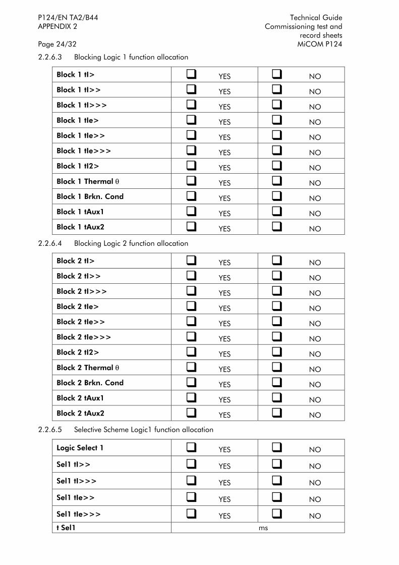
P124/EN TA2/B44 Technical Guide APPENDIX 2 Commissioning test and record sheets Page 24/32 MiCOM P124
2.2.6.3 Blocking Logic 1 function allocation
Block 1 tI> ! YES ! NO
Block 1 tI>> ! YES ! NO
Block 1 tI>>> ! YES ! NO
Block 1 tIe> ! YES ! NO
Block 1 tIe>> ! YES ! NO
Block 1 tIe>>> ! YES ! NO
Block 1 tI2> ! YES ! NO
Block 1 Thermal θ ! YES ! NO
Block 1 Brkn. Cond ! YES ! NO
Block 1 tAux1 ! YES ! NO
Block 1 tAux2 ! YES ! NO
2.2.6.4 Blocking Logic 2 function allocation
Block 2 tI> ! YES ! NO
Block 2 tI>> ! YES ! NO
Block 2 tI>>> ! YES ! NO
Block 2 tIe> ! YES ! NO
Block 2 tIe>> ! YES ! NO
Block 2 tIe>>> ! YES ! NO
Block 2 tI2> ! YES ! NO
Block 2 Thermal θ ! YES ! NO
Block 2 Brkn. Cond ! YES ! NO
Block 2 tAux1 ! YES ! NO
Block 2 tAux2 ! YES ! NO
2.2.6.5 Selective Scheme Logic1 function allocation
Logic Select 1 ! YES ! NO
Sel1 tI>> ! YES ! NO
Sel1 tI>>> ! YES ! NO
Sel1 tIe>> ! YES ! NO
Sel1 tIe>>> ! YES ! NO
t Sel1 ms

Technical Guide P124/EN TA2/B44 Commissioning test and APPENDIX 2 record sheets MiCOM P124 Page 25/32
2.2.6.6 Selective Scheme Logic2 function allocation
Logic Select 2 ! YES ! NO
Sel2 tI>> ! YES ! NO
Sel2 tI>>> ! YES ! NO
Sel2 tIe>> ! YES ! NO
Sel2 tIe>>> ! YES ! NO
t Sel2 ms

P124/EN TA2/B44 Technical Guide APPENDIX 2 Commissioning test and record sheets Page 26/32 MiCOM P124
2.2.6.7 OUTPUT RELAYS allocation
2.2.6.7.A OUTPUT RELAYS allocation (RL2 to RL4)
Functions RL 2 RL 3 RL 4
Trip ! YES ! NO ! YES ! NO ! YES ! NO
I> ! YES ! NO ! YES ! NO ! YES ! NO
tI> ! YES ! NO ! YES ! NO ! YES ! NO
I>> ! YES ! NO ! YES ! NO ! YES ! NO
tI>> ! YES ! NO ! YES ! NO ! YES ! NO
I>>> ! YES ! NO ! YES ! NO ! YES ! NO
tI>>> ! YES ! NO ! YES ! NO ! YES ! NO
Ie> ! YES ! NO ! YES ! NO ! YES ! NO
tIe> ! YES ! NO ! YES ! NO ! YES ! NO
Ie>> ! YES ! NO ! YES ! NO ! YES ! NO
tIe>> ! YES ! NO ! YES ! NO ! YES ! NO
Ie>>> ! YES ! NO ! YES ! NO ! YES ! NO
tIe>>> ! YES ! NO ! YES ! NO ! YES ! NO
tI< ! YES ! NO ! YES ! NO ! YES ! NO
tI2> ! YES ! NO ! YES ! NO ! YES ! NO
Therm Alarm ! YES ! NO ! YES ! NO ! YES ! NO
Therm Trip ! YES ! NO ! YES ! NO ! YES ! NO
CB Alarm ! YES ! NO ! YES ! NO ! YES ! NO
52 Fail ! YES ! NO ! YES ! NO ! YES ! NO
Brkn Cond ! YES ! NO ! YES ! NO ! YES ! NO
CB Fail ! YES ! NO ! YES ! NO ! YES ! NO
CB Close ! YES ! NO ! YES ! NO ! YES ! NO
tAux1 ! YES ! NO ! YES ! NO ! YES ! NO
tAux2 ! YES ! NO ! YES ! NO ! YES ! NO
79 Run ! YES ! NO ! YES ! NO ! YES ! NO
79 Trip ! YES ! NO ! YES ! NO ! YES ! NO
Active Group ! YES ! NO ! YES ! NO ! YES ! NO

Technical Guide P124/EN TA2/B44 Commissioning test and APPENDIX 2 record sheets MiCOM P124 Page 27/32
2.2.6.7.B OUTPUT RELAYS allocation (RL5 and RL6)
Functions RL 5 RL 6
Trip ! YES ! NO ! YES ! NO
I> ! YES ! NO ! YES ! NO
tI> ! YES ! NO ! YES ! NO
I>> ! YES ! NO ! YES ! NO
tI>> ! YES ! NO ! YES ! NO
I>>> ! YES ! NO ! YES ! NO
tI>>> ! YES ! NO ! YES ! NO
Ie> ! YES ! NO ! YES ! NO
tIe> ! YES ! NO ! YES ! NO
Ie>> ! YES ! NO ! YES ! NO
tIe>> ! YES ! NO ! YES ! NO
Ie>>> ! YES ! NO ! YES ! NO
tIe>>> ! YES ! NO ! YES ! NO
tI< ! YES ! NO ! YES ! NO
tI2> ! YES ! NO ! YES ! NO
Therm Alarm ! YES ! NO ! YES ! NO
Therm Trip ! YES ! NO ! YES ! NO
CB Alarm ! YES ! NO ! YES ! NO
52 Fail ! YES ! NO ! YES ! NO
Brkn Cond ! YES ! NO ! YES ! NO
CB Fail ! YES ! NO ! YES ! NO
CB Close ! YES ! NO ! YES ! NO
tAux1 ! YES ! NO ! YES ! NO
tAux2 ! YES ! NO ! YES ! NO
79 Run ! YES ! NO ! YES ! NO
79 Trip ! YES ! NO ! YES ! NO
Active Group ! YES ! NO ! YES ! NO

P124/EN TA2/B44 Technical Guide APPENDIX 2 Commissioning test and record sheets Page 28/32 MiCOM P124
2.2.6.8 Configuration of the latch of the output relays RL2 to RL6
Output 2 ! YES ! NO
Output 3 ! YES ! NO
Output 4 ! YES ! NO
Output 5 ! YES ! NO
Output 6 ! YES ! NO

Technical Guide P124/EN TA2/B44 Commissioning test and APPENDIX 2 record sheets MiCOM P124 Page 29/32
2.2.6.9 LOGIC INPUT allocation
2.2.6.9.A Inputs
! None ! Unlatch ! 52a
! 52b ! CB FLT ! Aux 1
! Aux 2 ! Blk Log (1) ! Blk Log (2)
! Strt Dist ! Cold L PU ! Log Sel 1
! Log Sel 2 ! Change Set ! θ Reset
Input 1
! Block - 79 ! Trip Circ ! Start tBf
! None ! Unlatch ! 52a
! 52b ! CB FLT ! Aux 1
! Aux 2 ! Blk Log (1) ! Blk Log (2)
! Strt Dist ! Cold L PU ! Log Sel 1
! Log Sel 2 ! Change Set ! θ Reset
Input 2
! Block - 79 ! Trip Circ ! Start tBf
! None ! Unlatch ! 52a
! 52b ! CB FLT ! Aux 1
! Aux 2 ! Blk Log (1) ! Blk Log (2)
! Strt Dist ! Cold L PU ! Log Sel 1
! Log Sel 2 ! Change Set ! θ Reset
Input 3
! Block - 79 ! Trip Circ ! Start tBf
! None ! Unlatch ! 52a
! 52b ! CB FLT ! Aux 1
! Aux 2 ! Blk Log (1) ! Blk Log (2)
! Strt Dist ! Cold L PU ! Log Sel 1
! Log Sel 2 ! Change Set ! θ Reset
Input 4
! Block - 79 ! Trip Circ ! Start tBf
! None ! Unlatch ! 52a
! 52b ! CB FLT ! Aux 1
! Aux 2 ! Blk Log (1) ! Blk Log (2)
! Strt Dist ! Cold L PU ! Log Sel 1
! Log Sel 2 ! Change Set ! θ Reset
Input 5
! Block - 79 ! Trip Circ ! Start tBf

P124/EN TA2/B44 Technical Guide APPENDIX 2 Commissioning test and record sheets Page 30/32 MiCOM P124
2.2.6.9.B t AUX
Aux 1 : Time tAux 1 ms
Aux 2 : Time tAux 2 ms
2.2.6.10 BROKEN CONDUCTOR
Brkn Cond ! YES ! NO
tBC ms
RATIO I2/I1 %
2.2.6.11 Cold Load Pick up
Cold Load PU ? ! YES ! NO
tI> ? ! YES ! NO
tI>> ? ! YES ! NO
tI>>> ? ! YES ! NO
tIe> ? ! YES ! NO
tIe>> ? ! YES ! NO
tIe>>> ? ! YES ! NO
t2> ? ! YES ! NO
T Therm ? ! YES ! NO
Level %
tCL ms
2.2.6.12 CIRCUIT BREAKER FAILURE
CB Fail ? ! YES ! NO
I< % In
tBF ms
Block I> ? ! YES ! NO
Block Ie> ? ! YES ! NO

Technical Guide P124/EN TA2/B44 Commissioning test and APPENDIX 2 record sheets MiCOM P124 Page 31/32
2.2.6.13 CIRCUIT BREAKER SUPERVISION
CT Supervision ! YES ! NO
t SUP s
CB Open S'vision ! YES ! NO
CB Open Time ms
CB Close S'vision ! YES ! NO
CB Close Time ms
CB Open Alarm? ! YES ! NO
CB Open NB
Σ Amps(n)? ! YES ! NO
n
t Open Pulse ms
t Close Pulse ms
2.2.7 RECORDS Menu
2.2.7.1 DISTURBANCE RECORD
Pre-time ms
Post-time ms
Disturb Rec Trig ! SUR INST. ! ON TRIP
2.2.7.2 TIME PEAK VALUE
Time Window mn

P124/EN TA2/B44 Technical Guide APPENDIX 2 Commissioning test and record sheets Page 32/32 MiCOM P124
BLANK PAGE


Schneider Electric 35 rue Joseph Monier 92506 Rueil-Malmaison FRANCE
Phone: +33 (0) 1 41 29 70 00 Fax: +33 (0) 1 41 29 71 00 www.schneider-electric.com Publishing: Schneider Electric
Publication: P124/EN T/E44 11/2010
© 2
010
Sch
neid
er E
lect
ric. A
ll rig
hts
rese
rved
.