mib20!30!40 operation manual 2003_05
TRANSCRIPT

7/22/2019 Mib20!30!40 Operation Manual 2003_05
http://slidepdf.com/reader/full/mib203040-operation-manual-200305 1/106
Operation Instructions
MIB20_30_40 OPERATION MANUAL 2003_05 - 1 -
Operating InstructionsMAGSTOP Traffic Barrier
MIB 20/30/40MLC Controller Unit
Version 2003_05

7/22/2019 Mib20!30!40 Operation Manual 2003_05
http://slidepdf.com/reader/full/mib203040-operation-manual-200305 2/106
Operation Instructions
MIB20_30_40 OPERATION MANUAL 2003_052
TABLE OF CONTENTS
1.0 SAFETY ...............................................................................................................................................................5
1.1 SAFETY SYMBOLS USED IN THIS HANDBOOK .................................................................................................................................. 5 1.2 GENERAL SAFETY INFORMATION ...................................................................................................................................................6 1.3 I NTENDED USE ...............................................................................................................................................................................6 1.4 WARNING AND SAFETY SIGNAGE ...................................................................................................................................................6 1.5 SAFETY R EQUIREMENTS ................................................................................................................................................................7 1.6 OPERATIONAL SAFETY...................................................................................................................................................................7 1.7 TECHNICAL DEVELOPMENTS..........................................................................................................................................................8 1.8 WARRANTY ...................................................................................................................................................................................8
2.0 INSTALLATION.....................................................................................................................................................9
2.1 GUIDELINES FOR FOUNDATION......................................................................................................................................................9 2.1 MOUNTING THE HOUSING TO THE GROUND.................................................................................................................................. 10
3.0 OPERATING THE MIB* BARRIER GATE..............................................................................................................15
4.0 MLC CONTROLLER............................................................................................................................................15
4.1 GENERAL.....................................................................................................................................................................................15 4.1 MLC CONTROLLER SETUP ..........................................................................................................................................................17 4.2 DISPLAY INFORMATION ............................................................................................................................................................... 18 4.3 PROGRAMMING AND READING THE OPERATING DATA.................................................................................................................. 19 4.3.1.1 PROGRAMMING MODES SHORT DESCRIPTION .........................................................................................................................20
4.3.1.2 SHORT DESCRIPTION OF THE GENERAL OPERATING DATA: ..................................................................................................... 20 5.0 PROGRAMMING MODES..................................................................................................................................21
5.1 AVAILABLE PROGRAM MODES AND FUNCTIONS ..........................................................................................................................22 5.1.1 PROGRAM 1 (MODE 1): ............................................................................................................................................................. 23 5.1.2 PROGRAM 2 (MODE 2): ............................................................................................................................................................. 24 5.1.3 PROGRAM 3 (MODE 3): ............................................................................................................................................................. 25 5.1.4 PROGRAM 4 (MODE 4): ............................................................................................................................................................. 26 5.1.5 PROGRAM 5 (MODE 5): ............................................................................................................................................................. 27 5.1.6 PROGRAM 6 (MODE 6): ............................................................................................................................................................. 29 5.1.7 PROGRAM 7 (MODE 7): ............................................................................................................................................................. 31 5.1.8 PROGRAM 8 (MODE 8): ............................................................................................................................................................. 32
6.0 TORQUE TIME SETTINGS ..................................................................................................................................33
6.1 HOW TO ADJUST THE TORQUE TIME: ............................................................................................................................................33
7.0 HOLD OPEN TIMER...........................................................................................................................................34
7.1 HOW TO ADJUST THE HOLD OPEN TIMER : .....................................................................................................................................34
8.0 LOOP DETECTOR SENSITIVITY ..........................................................................................................................35
8.1 HOW TO ADJUST THE LOOP A SENSITIVITY: ................................................................................................................................. 35
9.0 CONFIGURING THE LOOP DETECTORS..............................................................................................................36

7/22/2019 Mib20!30!40 Operation Manual 2003_05
http://slidepdf.com/reader/full/mib203040-operation-manual-200305 3/106
Operation Instructions
MIB20_30_40 OPERATION MANUAL 2003_05 - 3 -
9.1 SAFETY/CLOSING LOOP A........................................................................................................................................................... 36 9.2 LOOP A MODE FUNCTION ............................................................................................................................................................ 37
9.2.1 Detector Mode A............................................................................................................................................................................... 37
9.2.2 Directional Logic Loop A ................................................................................................................................................................. 37 9.3.1 Detector mode B ............................................................................................................................................................................... 40 9.3.2 Directional Logic Loop B ................................................................................................................................................................. 40
10.0 LOOP FREQUENCY..........................................................................................................................................42
10.1 HOW TO VIEW THE LOOP FREQUENCY:....................................................................................................................................... 42 10.2 HOW TO CHANGE THE LOOP FREQUENCY:.................................................................................................................................. 43
11.0 RELAY K1 OUTPUT..........................................................................................................................................44
12.0 ERROR CODE..................................................................................................................................................46
13.0 LANGUAGE SETTING......................................................................................................................................46
14.0 DEFAULT SETTINGS........................................................................................................................................47
15.0 EXTENDED MENU SETTINGS: .........................................................................................................................48
15.1 ADJUSTING THE SAFETY ANGLE:................................................................................................................................................ 49 15.2 OPERATING HOUR DISPLAY: ...................................................................................................................................................... 50 15.3 GATE CYCLE COUNTER : ............................................................................................................................................................ 50 15.4 R EADING THE BRAKE POINTS:................................................................................................................................................... 51 15.5 R ESETTING THE BARRIER AFTER POWER FAILURE:..................................................................................................................... 51 15.6 TEST MODE ............................................................................................................................................................................... 52
16.0 INSTALLING THE INDUCTION LOOPS..............................................................................................................54
16.1 GENERAL INDUCTION LOOP FUNCTIONALITY............................................................................................................................. 54
16.2 LOOP I NDUCTANCE ................................................................................................................................................................... 54 16.2.1 I NDUCTANCE .......................................................................................................................................................................... 54 16.2.2 VEHICLE DETECTION .............................................................................................................................................................. 55 16.2.3 WIRE TURNS REQUIRED FOR LOOPS ........................................................................................................................................ 55 16.2.4 LOOP I NDUCTANCE CALCULATIONS ....................................................................................................................................... 56 16.3 LOOP DETECTOR SENSITIVITY................................................................................................................................................... 57 16.4 I NSTALLING A I NDUCTION LOOP ............................................................................................................................................... 57 16.4.1 USAGE OF PRE-MANUFACTURED LOOPS................................................................................................................................. 57 16.4.2 SELF-MADE LOOPS ................................................................................................................................................................ 58 16.4.3 LOOP LEAD WIRES ................................................................................................................................................................. 58 16.4.4 HOW DEEP SHOULD THE LOOP WIRES BE INSTALLED?............................................................................................................. 59 16.4.5 LOOP DISTANCE FROM OBJECTS:............................................................................................................................................. 60
17.0 COMMISSIONING...........................................................................................................................................61
17.1 COMMISSIONING PROCEDURE .................................................................................................................................................... 61 17.3 STANDARD CONFIGURATION:.................................................................................................................................................... 62 17.3.1 PARKING OR ACCESS CONTROL CONFIGURATION: .............................................................................................................. 62 17.3.2 TOLL ROAD APPLICATION: ................................................................................................................................................. 62
18.0 INSTALLATION EXAMPLE: ..............................................................................................................................63
18.1 FREE EXIT OR ENTRY CONFIGURATION: ..................................................................................................................................... 63 18.1.1 FREE ENTRY OR EXIT LANE LAYOUT ...................................................................................................................................... 64 18.1.2 FREE ENTRY OR EXIT WIRING DIAGRAM: ................................................................................................................................ 65 18.2 E NTRY OR EXIT WITH ACCESS CONTROL: ................................................................................................................................... 66

7/22/2019 Mib20!30!40 Operation Manual 2003_05
http://slidepdf.com/reader/full/mib203040-operation-manual-200305 4/106
Operation Instructions
MIB20_30_40 OPERATION MANUAL 2003_054
18.2.1 ACCESS CONTROL LANE LAYOUT ...........................................................................................................................................67 18.2.2 ACCESS CONTROL LANE WIRING DIAGRAM ............................................................................................................................68
18.3 A
CCESSC
ONTROL ONE DIRECTION FREE IN/OUT OTHER DIRECTION
...........................................................................................69 18.3.1 ACCESS CONTROL I N FREE OUT LANE LAYOUT ..................................................................................................................... 70 18.3.2 ACCESS CONTROL I N FREE OUT LANE WIRING DIAGRAM ....................................................................................................... 71 18.4 MASTER SLAVE CONFIGURATION .............................................................................................................................................. 72 18.4.1 MASTER /SLAVE LANE LAYOUT .............................................................................................................................................. 74 18.4.2 MASTER SLAVE WIRING DIAGRAM..........................................................................................................................................75 18.5 TOLL R OAD APPLICATION:.........................................................................................................................................................76 18.5.1 TOLL R OAD LANE LAYOUT .....................................................................................................................................................77 18.5.2 TOLL R OAD WIRING DIAGRAM ................................................................................................................................................ 78
19.0 MIB* BARRIER WITH BOOM LOCK MECHANISM ............................................................................................79
20.0 MIB* BARRIER WITH BOOM LIGHTS ...............................................................................................................80
21.0 MECHANICAL OPERATION..............................................................................................................................81 21.1 SPRING BALANCE.......................................................................................................................................................................81 21.2 BARRIER ARM SUPPORT ............................................................................................................................................................. 83 21.2.1 PENDULUM SUPPORT............................................................................................................................................................... 83 21.2.2 SUPPORT POST ........................................................................................................................................................................83
22.0 TROUBLESHOOTING.......................................................................................................................................85
22.1 ADJUSTING THE BOOM POSITION SENSOR ................................................................................................................................... 85 22.2 BOOM SENSOR OUT OF ADJUSTMENT .........................................................................................................................................88 22.3 LOOP DETECTOR ERROR ............................................................................................................................................................ 91 22.4 GATE DOES NOT CLOSE .............................................................................................................................................................. 92 22.5 GATE DOES NOT OPEN ................................................................................................................................................................93 22.6 HOW TO CHANGE FROM RIGHT-HANDED GATE TO LEFT- HANDED? ............................................................................................94
23.0 TECHNICAL DATA...........................................................................................................................................96
23.1 MAGSTOP BARRIERS .............................................................................................................................................................. 96 23.2 CONTROLLER ............................................................................................................................................................................. 96
24. MAINTENANCE.................................................................................................................................................98
24.1 CHANGING THE R UBBER E ND STOP ...........................................................................................................................................98 24.2 CHECKING THE EXTERIOR OF CABINET .....................................................................................................................................98 24.3 CHECK THE BARRIER ARM AND THE ATTACHMENT KIT ..............................................................................................................98 24.4 CHECKING THE LOOP DETECTORS AND LOOP WIRES ................................................................................................................98 24.5 CHECK SAFETY SIGNAGE ........................................................................................................................................................... 98 24.5 MAINTENANCE SERVICE R ECORD.............................................................................................................................................. 99 24.5 MAINTENANCE SERVICE R ECORD............................................................................................................................................ 100
25. SPARE PARTS..................................................................................................................................................101

7/22/2019 Mib20!30!40 Operation Manual 2003_05
http://slidepdf.com/reader/full/mib203040-operation-manual-200305 5/106
Operation Instructions
MIB20_30_40 OPERATION MANUAL 2003_05 - 5 -
1.0 Safety
1.1 Safety symbols used in this handbook
The following symbols are used in this operating instruction to indicate potential risksand other safety information.
Caution!This symbol is used in this manual to designate those actions or states whichrepresent a potential hazard to property and equipment. Please read theseinstructions very carefully.
Note!This symbol is used in this manual to designate useful information for theoperator.
Warning!This symbol is used in this manual to warn installer for potential harm. Pleaseread these instructions very carefully.

7/22/2019 Mib20!30!40 Operation Manual 2003_05
http://slidepdf.com/reader/full/mib203040-operation-manual-200305 6/106
Operation Instructions
MIB20_30_40 OPERATION MANUAL 2003_056
1.2 General safety information
This MAGSTOP barrier system has been designed, built and tested using state-of-the-arttechnology and left our factory only after passing stringent safety and reliability criteria.Nevertheless the barrier system can represent a risk to persons and property if it is notinstalled and operated correctly. These operating instructions must therefore be read intheir entirety and all safety information contained therein must be complied with.The manufacturer shall refuse to accept liability and shall withdraw warranty if thisbarrier system is used incorrectly or is used for a purpose for which it was not intended.
1.3 Intended use
The MAGSTOP MIB 20/30/40 barriers are designed to control vehicular (see pictogrambelow) access and exits to car parks, car parking garages, access control applications andhighways.The MAGTRONIC control units have been specially designed for controlling Magneticbarriers.Any other use of these barrier systems is not permitted.Modifications or changes to the barrier or to the control modules are prohibited.Only original Magnetic spare parts and accessories shall be used.
Figure 2
Figure 1
1.4 Warning and safety signage
The Magnetic Automation Corp. MIB barriers come with two (2) safety warning labels
(see Figure 1 above) that must be applied to the barrier housing so it can easily be seenwhen a pedestrian, bicycle users, or motorized vehicle uses the lane. MagneticAutomation Corp. requires that you use universally identifiable pictograms in allentrance/exit lanes, roadways, post, and walls. It is strongly recommended to paint a“NO PEDESTRIAN” pictogram on the roadway immediately adjacent to the parkingbarrier gate. The barrier arms come already with the safety labels (see Figure 2 above).Removing those safety labels voids any manufacturer’s liability.
7/22/2019 Mib20!30!40 Operation Manual 2003_05
http://slidepdf.com/reader/full/mib203040-operation-manual-200305 7/106
Operation Instructions
MIB20_30_40 OPERATION MANUAL 2003_05 - 7 -
1.5 Safety Requirements
- Use vibrant colors on parking equipment- Always provide proper signage, both on the road way and on other equipment- Maintain manufacturers warning stickers on gate housing and gate arms.- Always require that sidewalks are parallel to entrance and exit lanes, or require havingpedestrian entrances on opposite side of vehicle entrance and exit.
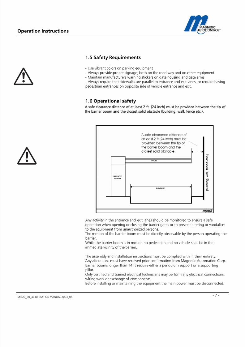
1.6 Operational safety
A safe clearance distance of at least 2 ft (24 inch) must be provided between the tip ofthe barrier boom and the closest solid obstacle (building, wall, fence etc.).
Any activity in the entrance and exit lanes should be monitored to ensure a safeoperation when opening or closing the barrier gates or to prevent altering or vandalismto the equipment from unauthorized persons.The motion of the barrier boom must be directly observable by the person operating thebarrier.
While the barrier boom is in motion no pedestrian and no vehicle shall be in theimmediate vicinity of the barrier.
The assembly and installation instructions must be complied with in their entirety.Any alterations must have received prior confirmation from Magnetic Automation Corp.Barrier booms longer than 14 ft require either a pendulum support or a supportingpillar.Only certified and trained electrical technicians may perform any electrical connections,wiring work or exchange of components.Before installing or maintaining the equipment the main power must be disconnected.

7/22/2019 Mib20!30!40 Operation Manual 2003_05
http://slidepdf.com/reader/full/mib203040-operation-manual-200305 8/106
Operation Instructions
MIB20_30_40 OPERATION MANUAL 2003_058
1.7 Technical developments The manufacturer reserves the right to modify, without prior notice, the technicalspecifications in order to accommodate the latest technical developments. MagneticAutomation Corp. will provide information on the status of existing operatinginstructions and on any alterations and extensions that may be relevant.
1.8 Warranty
Magnetic provides a limited warranty on its barriers that covers all mechanical andelectrical components, but excludes parts subject to wear and tear, for a period of twoyears from the date of first use or for a maximum of three years from the date on whichthe system was delivered provided that the operating instructions have been compliedwith, no unauthorized servicing of machine components has taken place, and that nomechanical damage to the machines is evident.Please refer to our Warranty Statement.
NOTE: NONE COMPLYANCE WITH THE ABOVE SAFETYREQUIREMENTS (all of Chapter 1) SHALL VOID ANY MANUFACTURERSLIABILITY
COPYRIGHT
2001 Magnetic Automation Corp.All rights reserved. No part of this publication may bereproduced, transmitted, transcribed, stored in a retrievalsystem, or translated into any language in any form by anymeans without the written permission of MagneticAutomation Corp.
First Printing: 2001

7/22/2019 Mib20!30!40 Operation Manual 2003_05
http://slidepdf.com/reader/full/mib203040-operation-manual-200305 9/106
Operation Instructions
MIB20_30_40 OPERATION MANUAL 2003_05 - 9 -
2.0 Installation2.1 Guidelines for Foundation
To ensure that the equipment is solidly bolted to the ground under all operationconditions, a foundation with the following dimensions shall be provided:Depth of foundation: at least 3ft (frost-depth)Base area of foundation: 19” x 23 ½”
The base of the foundation is 4” wider towards the vehicle passage side, than in othersection of the foundation (see Fig. S0225).
Fig. S0225View of the foundation
1 Anchor bolts (4x)2 Empty conduit for induction loop lead wire, dia. ½”3 Conduit for power cables, dia. 1”4 Conduit for control cables, dia. ½”5 Concrete foundation
1
2
3
4
5
3 1 1 / 2
S0225
Foundation atfrost-line depth 3’
Concretefoundation
PC 250
1 Conduit 1/2” for loop lead w
1 Conduit 3/4” for power supmust be extended and conneto junction box 1 Conduit 1/2”” for control
7/22/2019 Mib20!30!40 Operation Manual 2003_05
http://slidepdf.com/reader/full/mib203040-operation-manual-200305 10/106
Operation Instructions
MIB20_30_40 OPERATION MANUAL 2003_0510
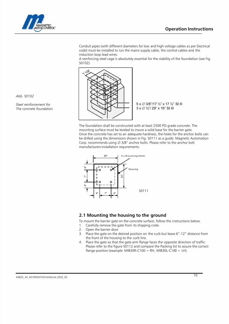
Conduit pipes (with different diameters for low and high voltage cables as per Electricalcode) must be installed to run the mains supply cable, the control cables and theinduction loop lead wires.A reinforcing steel cage is absolutely essential for the stability of the foundation (see Fig.S0102).
Abb. S0102
Steel reinforcement forThe concrete foundation
The foundation shall be constructed with at least 2500 PSI grade concrete. Themounting surface must be leveled to insure a solid base for the barrier gate.Once the concrete has set to an adequate hardness, the holes for the anchor bolts canbe drilled using the dimensions shown in Fig. S0111 as a guide. Magnetic AutomationCorp. recommends using ∅ 3/8” anchor bolts. Please refer to the anchor boltmanufacturers installation requirements.
2.1 Mounting the housing to the ground
To mount the barrier gate on the concrete surface, follow the instructions below.
1. Carefully remove the gate from its shipping crate.2. Open the barrier door3. Place the gate on the desired position on the curb but leave 6”-12” distance from
the front of the housing to the curb line.4. Place the gate so that the gate arm flange faces the opposite direction of traffic.
Please refer to the figure S0112 and compare the Packing list to assure the correctflange position (example: MIB30R-C100 = RH, MIB30L-C100 = LH).
5 x ∅ 3/8”/17 ½” x 17 ½” St III
3 x ∅ ½”/ 29” x 16” St III
6 "
6 "
7 "
7"6" 6"
20"
2 0 "
4 x M ount ing Holes
Housing
S0111

7/22/2019 Mib20!30!40 Operation Manual 2003_05
http://slidepdf.com/reader/full/mib203040-operation-manual-200305 11/106
Operation Instructions
MIB20_30_40 OPERATION MANUAL 2003_05 - 11 -
5. Using a marker, follow the outside and inside contours to the concrete.
6. Remove barrier gate.
7. Using a pencil, mark the location of the mounting holes on the concrete. (See fig.S0111 for dimensions).
8. Drill all four mounting holes and insert the bolts. (Please refer to anchor boltmanufacturers installation specifications). Make sure that the bolts stand up at least2 inches above the concrete surface.
9. Place the gate on top of the previous marked area.
10. Using the supplied U-channel (in accessory box) secure the gate to the concrete (seeFig. S0106).
6 "
6 "
7 "
7"6" 6"
20"
2 0 "
4 x M ount ing Holes
Housing
S0111

7/22/2019 Mib20!30!40 Operation Manual 2003_05
http://slidepdf.com/reader/full/mib203040-operation-manual-200305 12/106
Operation Instructions
MIB20_30_40 OPERATION MANUAL 2003_0512
1 barrier housing
2 nut
3 lock washer
4 small flat washer
5 large flat washer
6 anchor bolt7 U-rail8 concrete foundation
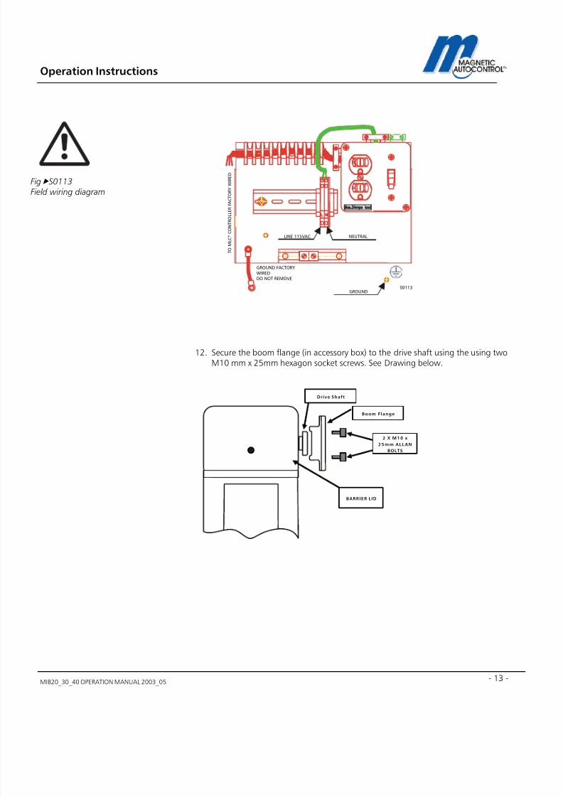
11. Attach the field wiring to the proper terminals at the main power board. SeeDrawing S0113 below. Make certain that the main circuit breaker is switched OFF.Connect all electrical wiring exactly as directed in the Connection Diagram.
1
2
3
4
5
6
7
8
S0106
Abb,S0106Mounting the barrier housing to the
foundation
7/22/2019 Mib20!30!40 Operation Manual 2003_05
http://slidepdf.com/reader/full/mib203040-operation-manual-200305 13/106
Operation Instructions
MIB20_30_40 OPERATION MANUAL 2003_05 - 13 -
12. Secure the boom flange (in accessory box) to the drive shaft using the using twoM10 mm x 25mm hexagon socket screws. See Drawing below.
LINE 115VAC NEUTRAL
GROUNDS0113
T O M L C * C O N T R O L L E R F A C T O R Y W I R E D
GROUND FACTORY
WIRED
DO NOT REMOVE
Fig S0113Field wiring diagram
2 X M10 x
25m m ALLAN
BOLTS
Drive Shaft
Boom Flange
BARRIER LID
7/22/2019 Mib20!30!40 Operation Manual 2003_05
http://slidepdf.com/reader/full/mib203040-operation-manual-200305 14/106
Operation Instructions
MIB20_30_40 OPERATION MANUAL 2003_0514
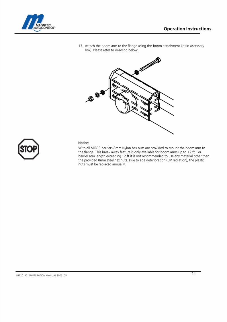
13. Attach the boom arm to the flange using the boom attachment kit (in accessorybox). Please refer to drawing below.
Notice:
With all MIB30 barriers 8mm Nylon hex nuts are provided to mount the boom arm tothe flange. This break away feature is only available for boom arms up to 12 ft. Forbarrier arm length exceeding 12 ft it is not recommended to use any material other thenthe provided 8mm steel hex nuts. Due to age deterioration (UV radiation), the plasticnuts must be replaced annually.

7/22/2019 Mib20!30!40 Operation Manual 2003_05
http://slidepdf.com/reader/full/mib203040-operation-manual-200305 15/106
Operation Instructions
MIB20_30_40 OPERATION MANUAL 2003_05 - 15 -
3.0 Operating the MIB* Barrier Gate
In automatic operation, the MIB* Barrier gate can be operated using following devices:- Ticket Spitters
- Vehicle Detectors
- Card Readers
- Coin and Token acceptors
- Radio Controllers
- Switches, Push buttons, and other devices.
4.0 MLC Controller
4.1 General
The MLC control unit (Magnetic Lane Controller) has been specially designed for use withMIB 20/30/40 barrier gates.All standard configurations can be achieved with this new generation controller.Via a potentiometer (boom position sensor), located at the motor drive shaft, theposition of the barrier arm is continuously detected and the MLC controller evaluates theinformation.This replaces the limit switch that is used in conventional barrier control systems. Thecombination of the potentiometer and the MLC unit guarantees the best possible controlof the barrier boom movement.The controller also has a 16-digit LCD display that shows the current settings and in/out -put stages at any time.Software modifications are normally included at the factory but they can also be loadedvery easily into the controller unit at some later date by connecting a software memorycard via the interface connector.The barrier is factory wired and supplied ready for immediate connection.
Warning!The following description isbased on the standardparameter S 24008.Other parameters sets are notdescribed in this manual.

7/22/2019 Mib20!30!40 Operation Manual 2003_05
http://slidepdf.com/reader/full/mib203040-operation-manual-200305 16/106
Operation Instructions
MIB20_30_40 OPERATION MANUAL 2003_0516
00

7/22/2019 Mib20!30!40 Operation Manual 2003_05
http://slidepdf.com/reader/full/mib203040-operation-manual-200305 17/106
Operation Instructions
MIB20_30_40 OPERATION MANUAL 2003_05 - 17 -
4.1 MLC Controller Setup
1 16- digit liquid crystal display (LCD) for indicating operational and programmed data2. Rotary selector switch to select operating and setup modes
3. Black button open/scroll/save (operating mode/programming mode)4. White button close/enter (operating mode/programming mode)5. Terminal strip – control voltage side6. Terminal strip – Motor and relay output
NOTE:
THE MLC* CONTROLLER HAS UNIVERSAL MAIN VOLTAGE INPUT (85-V-265V) BUT THEMOTOR DOESN’T. PLEASE CHECK THE SERAIL NUMBER LABEL FOR THE BARRIER FORINPUT VOLTAGE.
1 2 3 4 5 6
Abb.S0227MLC control panel
00

7/22/2019 Mib20!30!40 Operation Manual 2003_05
http://slidepdf.com/reader/full/mib203040-operation-manual-200305 18/106
Operation Instructions
MIB20_30_40 OPERATION MANUAL 2003_0518
4.2 Display information
Normal operating mode, rotary switch set to ‘0’. Following information is displayed:Note:IN5 (external safety input) must be made (activated) in order for the barrier gate tooperate. Standard factory setup is a jumper wire to activate this input and using theinternal Loop A as safety device.
Abb.S0228Display information
7/22/2019 Mib20!30!40 Operation Manual 2003_05
http://slidepdf.com/reader/full/mib203040-operation-manual-200305 19/106
Operation Instructions
MIB20_30_40 OPERATION MANUAL 2003_05 - 19 -
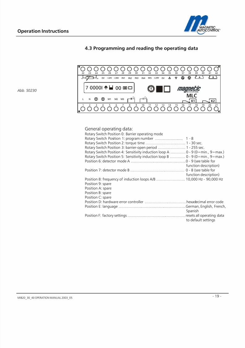
4.3 Programming and reading the operating data
General operating data:Rotary Switch Position 0: Barrier operating modeRotary Switch Position 1: program number …………………. 1 - 8Rotary Switch Position 2: torque time ………………………….. 1 - 30 sec.Rotary Switch Position 3: barrier-open period …………………. 1 - 255 sec.Rotary Switch Position 4: Sensitivity induction loop A ………… 0 - 9 (0=min., 9=max.)Rotary Switch Position 5: Sensitivity induction loop B ………… 0 - 9 (0=min., 9=max.)Position 6: detector mode A …………………………………….. 0 - 9 (see table for
function description)Position 7: detector mode B ……………………………………. 0 - 8 (see table for
function description)Position 8: frequency of induction loops A/B ………………….. 10,000 Hz - 90,000 Hz
Position 9: sparePosition A: sparePosition B: sparePosition C: sparePosition D: hardware error controller ……………………………hexadecimal error codePosition E: language ……………………………………………... German, English, French,
SpanishPosition F: factory settings ………………………………………. resets all operating data
to default settings
Abb. S0230
M1
IN1 IN2 IN3 IN4 IN5
L NC C
0V 0V
M2 M3
272625242322 37363534333231302928 4241403938
A B
654321 16151413121110987 2120191817
K1 K2
bk rd
wh
00

7/22/2019 Mib20!30!40 Operation Manual 2003_05
http://slidepdf.com/reader/full/mib203040-operation-manual-200305 20/106
Operation Instructions
MIB20_30_40 OPERATION MANUAL 2003_0520
4.3.1.1 Programming modes short description
(Selector switch position ‘1’ see chapter 5.0 for detailed description):
Program number Function:
1 Barrier controlled by a potential-free switch
2 Dead man function
3 Barrier controlled by pulses from a single push button
4 Barrier controlled by pulses from two separate pushbuttons
5 Automatic with barrier-hold open timer
6 Automatic with barrier-hold open timer, opening loopdisabled when vehicle passes from opposite direction
7 Automatic without barrier-hold open timer
8 Automatic without barrier-hold open timer, opening loopdisabled when vehicle passes from opposite direction
4.3.1.2 Short description of the general operating data:
Torque time:Pos.2
Period for which the barrier motor has full torque, whentime expires controller switches to low powerconsumption.
Barrier-hold opentimer Pos.3:
Time after which the barrier closes automatically if novehicle has passed through the safety device.
Loop sensitivityLoop A Pos. 4Loop B Pos. 5
Inductive loop Sensitivity levelA = safety/closing loop, B = opening / presence loop
Detector modeLoop A Pos. 6Loop B Pos. 7
Function of the loop detectors A/B and the relays K1/K2.See Section 6.5: ‘Adjusting the induction loops’.
Detectorfrequency Pos. 8
Displays current frequency for loop A and loop BSee Chapter 9.0 for more details.
K1 relay outputPos. B
This setting is only functioning when Mode Loop a = 0(disabled). The position when Relay K1 should switch canbe adjusted.
Hardware errorPos. D
Hexadecimal error code, only relevant for manufacturer’sown error detection procedures
LanguagePos. E
Language selection for LCD messages (German, English,French, Spanish)
Factory settings
Pos. F
Resets the operating data to the original default settings.
Caution! Use only in exceptional circumstances!

7/22/2019 Mib20!30!40 Operation Manual 2003_05
http://slidepdf.com/reader/full/mib203040-operation-manual-200305 21/106
Operation Instructions
MIB20_30_40 OPERATION MANUAL 2003_05 - 21 -
?
5.0 Programming Modes1.0 To select a Programming mode turn the rotary switch in position 1.
Display Message:
2.0 To change to different Program Mode press and hold both, the black and the whitebutton down. A cursor will appear below the number. Release both buttons.
3.0 When cursor appeared below the number use the black button to scroll throughthe available program modes.
4.0 When desired mode appeared on display press the white button.
Display Message:
5.0 In order to save your changes press the Black button
Display Message:
6.0 To return to the normal operating mode turn rotary switch to Position 1
program number X
X = Selected Program modenumberprogram number X
X = Current Program modenumber

7/22/2019 Mib20!30!40 Operation Manual 2003_05
http://slidepdf.com/reader/full/mib203040-operation-manual-200305 22/106
Operation Instructions
MIB20_30_40 OPERATION MANUAL 2003_0522
5.1 Available Program Modes and functions
Important note: The information provided here is based on the standard programS24008. Differences may exist to other standard programs or customized versions. Theseprograms are documented and attached to this standard manual as addendum.To find out what software is currently installed please read chapter 17.1. All externalequipment that uses the MLC* controller inputs (e.g. push buttons, light barriers, limitswitches) must be connected as potential free contacts. Contact Magnetic for advicebefore connecting any equipment that doesn’t meet those requirements.
Note:DO NOT CONNECT ANY DEVICE WHICH WOULD DELIVER ANY VOLTAGE OF ANY KINDTO THE INPUTS OF THE MLC* CONTROLLER.
Note:External safety devices other then the internal loop A of the MLC* controller must beconnected as normally closed contact to IN 5 (Terminal 32) and terminal 33 (+24VDC).If the internal loop A is used as safety device no additional wiring is necessary but ajumper wire between IN5 (terminal 32) and terminal 33 (+24VDC) is imperative. Thisjumper wire comes factory wired and loop A is active as safety device.
Following are the functional descriptions of the available Program Modes

7/22/2019 Mib20!30!40 Operation Manual 2003_05
http://slidepdf.com/reader/full/mib203040-operation-manual-200305 23/106
Operation Instructions
MIB20_30_40 OPERATION MANUAL 2003_05 - 23 -
5.1.1 Program 1 (Mode 1):
(Maintained contact)A potential free switch controls the barrier.
Contact closed = barrier closed. Contact open = barrier open.
Internal Loop A (safety loop) will not close the gate. Loop B can only operated as presence
loop.
Connections:
IN1 Terminal 27 and 28 = no function
IN2 Terminal 27 and 29 = no function
IN3 Terminal 27 and 30 = Contact closed=gate closed, Contact open=gate open.
IN4 Terminal 27 and 31 = no function
IN5 Terminal 31 and 33 = External Safety device (Normally closed contact). The safetydevice will not close the gate. Loop B can only be operated as presence loop.
Wiring Diagram:
Note:This program mode is mostly used when only one switch is available and a guard, who isin the vicinity of the barrier, operates the gate.When using other safety devices then the internal safety Loop A connect it to IN5 onterminal 32 and 33. The external safety device must use a NC contact and the existing
jumper wire must be removed. When no external safety device is used, a jumper wire onIN 5 (wired ex factory) is necessary to operate the gate.All inputs must be potential free (dry contacts) contacts.
1 0 m F C A P .
8 m F C A P .
Boom
Sensor
R e d
W h i t e
B l a c k
Motor
100V...250VAC
50/60HzProgram 1
Safety Loop
A
M 1
IN 1 IN 2 IN 3 IN 4 IN 5
L N
0V 0V
M 2 M 3
272625242322 37363534333231302928 4241403938
A B
654321 16151413121110987 2120191817
K1 K2
bk rd
wh
00 !
CC

7/22/2019 Mib20!30!40 Operation Manual 2003_05
http://slidepdf.com/reader/full/mib203040-operation-manual-200305 24/106
Operation Instructions
MIB20_30_40 OPERATION MANUAL 2003_0524
5.1.2 Program 2 (Mode 2):
Dead-man (Pulse to open, maintain contact to close). The gate closing input must beactivated (made) until the arm reaches the full down position.
Internal Loop A (safety loop) or the external safety device (IN5) will not close the gate.
Loop B can only operated as presence loop.
Connections:
IN1 Terminal 27 and 28 = Momentary Signal (pulse) to open the gate.
IN2 Terminal 27 and 29 = no function
IN3 Terminal 27 and 30 = Maintained Contact to close the gate
IN4 Terminal 27 and 31 = no function
IN5 Terminal 31 and 33 = External Safety device (Normally closed contact).
Wiring Diagram:
Note:This program mode is mostly used when a guard who is in the vicinity of the barrierguards the entrance or exit. When using other safety devices then the internal safety Loop A connect it to IN5 onterminal 32 and 33. The external safety device must use a NC contact and the existing
jumper wire must be removed. When no external safety device is used a jumper wire onIN 5 (wired ex factory) is necessary to operate the gate.All inputs must be potential free (dry contacts) contacts.
Boom
Sensor
R e d
W h i t e
B l a c k
Motor
100V...250VAC
50/60HzProgram 2
Safety Loop
A
M1
IN1 IN2 IN3 IN4 IN5
L NC C
0V 0V
M2 M3
272625242322 37363534333231302928 4241403938
A B
654321 16151413121110987 2120191817
K1 K2
bk rd
wh
00 !
1 0 m F C A P .
8 m F C A P .

7/22/2019 Mib20!30!40 Operation Manual 2003_05
http://slidepdf.com/reader/full/mib203040-operation-manual-200305 25/106
Operation Instructions
MIB20_30_40 OPERATION MANUAL 2003_05 - 25 -
5.1.3 Program 3 (Mode 3):
Pulse controlEach pulse (input) results in a change of travel direction (up/down) of the barrier arm.1st pulse: barrier opens, 2nd pulse: barrier closes, 3rd pulse: barrier opens, ... etc.
Internal Loop A (safety loop) or the external safety device (IN5) will not close the gate.
Loop B can only be operated as the presence loop.
Connections:
IN1 Terminal 27 and 28 = Momentary Signal 1st pulse: barrier opens, 2nd pulse: barriercloses, 3rd pulse: barrier opens, ... etc. IN2 Terminal 27 and 29 = no functionIN2 Terminal 27 and 29 = no function
IN3 Terminal 27 and 30 = no function
IN4 Terminal 27 and 31 = no function
IN5 Terminal 31 and 33 = External Safety device (Normally closed contact)
Wiring Diagram:
Note:This program mode is mostly used when a guard who is in the vicinity of the barrierguards the entrance or exit. When using other safety devices then the internal safety Loop A connect it to IN5 onterminal 32 and 33. The external safety device must use a NC contact and the existing
jumper wire must be removed. When no external safety device is used a jumper wire onIN 5 (wired ex factory) is necessary to operate the gate.All inputs must be potential free (dry contacts) contacts.
Boom
Sensor
R e d
W h i t e
B l a c k
Motor
100V...250VAC
50/60HzProgram 3
Safety Loop
A
M1
IN1 IN2 IN3 IN4 IN5
L NC C
0V 0V
M2 M3
272625242322 37363534333231302928 4241403938
A B
654321 16151413121110987 2120191817
K1 K2
bk rd
wh
00 !
1 0 m F C A P .
8 m F C A P .

7/22/2019 Mib20!30!40 Operation Manual 2003_05
http://slidepdf.com/reader/full/mib203040-operation-manual-200305 26/106
Operation Instructions
MIB20_30_40 OPERATION MANUAL 2003_0526
5.1.4 Program 4 (Mode 4):
Pulses from two different normally open devices control the barrier position.
Internal Loop A (safety loop) or the external safety device (IN5) will not close the gate.Loop B can only operated as presence loop.
Connections:
IN1 Terminal 27 and 28 = Momentary Signal gate openIN2 Terminal 27 and 29 = Override gate open (highest priority)
IN3 Terminal 27 and 30 = Momentary Signal gate close
IN4 Terminal 27 and 31 = no function
IN5 Terminal 31 and 33 = External Safety device (Normally closed contact)
Wiring Diagram:
Note:
This program mode is used mostly on toll road applications where lane controllerscontrol the gate and no automatic functioning is required.When using other safety devices then the internal safety Loop A connect it to IN5 onterminal 32 and 33. The external safety device must use a NC contact and the existing
jumper wire must be removed. When no external safety device is used a jumper wire onIN 5 (wired ex factory) is necessary to operate the gate.
Inputs on IN2 will override all existing closing inputs.
All inputs must be potential free (dry contacts) contacts..
Boom
Sensor
R e d
W h i t e
B l a c k
Motor
100V...250VAC
50/60Hz
Program 4
Safety Loop
A
M1
IN1 IN2 IN3 IN4 IN5
L NC C
0V 0V
M2 M3
272625242322 37363534333231302928 4241403938
A B
654321 16151413121110987 2120191817
K1 K2
bk rd
wh
00 !
1 0 m F C A P .
8 m F C A P .

7/22/2019 Mib20!30!40 Operation Manual 2003_05
http://slidepdf.com/reader/full/mib203040-operation-manual-200305 27/106
Operation Instructions
MIB20_30_40 OPERATION MANUAL 2003_05 - 27 -
5.1.5 Program 5 (Mode 5):
Automatic Mode.The barrier is opened by a pulse and/or opening loop and closes automatically after an
adjustable time, or immediately after the safety device (Loop A or external IN5) has been
passed or a closing input on IN3 has been given.
Connections:IN1 Terminal 27 and 28 = Momentary Signal gate openIN2 Terminal 27 and 29 = Override gate open (highest priority)
IN3 Terminal 27 and 30 = Momentary Signal gate close
IN4 Terminal 27 and 31 = no function
IN5 Terminal 31 and 33 = External Safety and gate Closing device (Normally closed
contact.
Wiring Diagram:
Note:
This program mode is used when automatic functioning of the gate is required. The gatereceives an opening command and closes when the vehicle passes through thesafety/closing loop after the adjustable hold-open time expires or when a closing inputon IN3 was made.When using other safety devices then the internal safety Loop A connect it to IN5 onterminal 32 and 33. The external safety device must use a NC contact and the existing
jumper wire must be removed. When no external safety device is used a jumper wire onIN 5 (wired ex factory) is necessary to operate the gate.
Inputs on IN2 will override all existing closing inputs.All inputs must be potential free (dry contacts) contacts
Boom
Sensor
Motor
Program 5
Loop
A
M1
IN1 IN2 IN3 IN4 IN5
L NC C
0V 0V
M2 M3
272625242322 37363534333231302928 4241403938
A B
654321 16151413121110987 2120191817K1 K2
bk rd
wh
00
1 0 m F C A P .
8 m F C A P .
Loop
B R e d
W h i t e
B l a c k
100V...250VAC
50/60Hz

7/22/2019 Mib20!30!40 Operation Manual 2003_05
http://slidepdf.com/reader/full/mib203040-operation-manual-200305 28/106
Operation Instructions
MIB20_30_40 OPERATION MANUAL 2003_0528
If Loop A is activated and loop B configured as opening loop the gate closes after thevehicle passed both loops, not immediately after leaving the safety loop.Logic: Loop A, AB,B, gate closes. See drawings below.
1.0 Gate closed, patron opens gate.
2.0 Gate opens and vehicle passes through Loop A, gate still in up Position.
3.0 Vehicle leaves Loop B and gate closes.
L O
O P
B
L O
O P A
Travel
Direction
L O O P
B
L O O P
A
Travel
Direct ion
L O O P
B
L O O
P
A
Travel
Direction
7/22/2019 Mib20!30!40 Operation Manual 2003_05
http://slidepdf.com/reader/full/mib203040-operation-manual-200305 29/106
Operation Instructions
MIB20_30_40 OPERATION MANUAL 2003_05 - 29 -
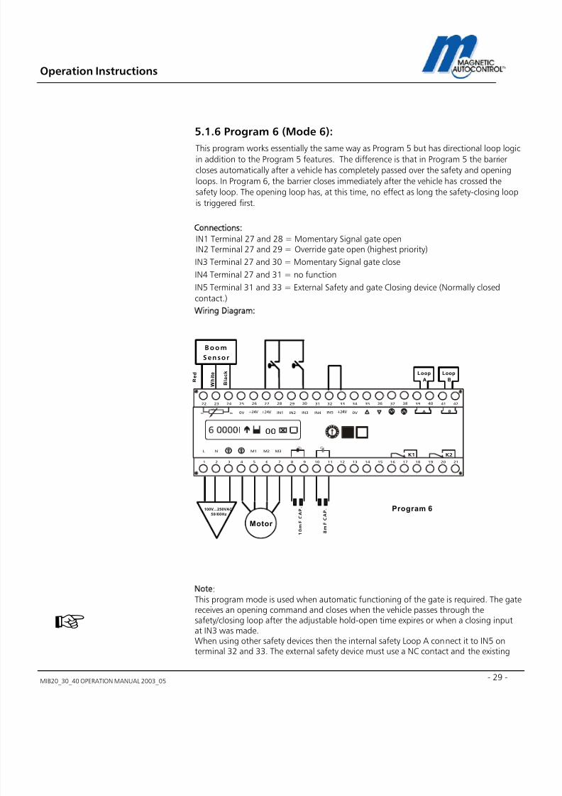
5.1.6 Program 6 (Mode 6):
This program works essentially the same way as Program 5 but has directional loop logic
in addition to the Program 5 features. The difference is that in Program 5 the barrier
closes automatically after a vehicle has completely passed over the safety and opening
loops. In Program 6, the barrier closes immediately after the vehicle has crossed the
safety loop. The opening loop has, at this time, no effect as long the safety-closing loop
is triggered first.
Connections:IN1 Terminal 27 and 28 = Momentary Signal gate openIN2 Terminal 27 and 29 = Override gate open (highest priority)
IN3 Terminal 27 and 30 = Momentary Signal gate close
IN4 Terminal 27 and 31 = no functionIN5 Terminal 31 and 33 = External Safety and gate Closing device (Normally closed
contact.)
Wiring Diagram:
Note:This program mode is used when automatic functioning of the gate is required. The gatereceives an opening command and closes when the vehicle passes through thesafety/closing loop after the adjustable hold-open time expires or when a closing inputat IN3 was made.When using other safety devices then the internal safety Loop A connect it to IN5 onterminal 32 and 33. The external safety device must use a NC contact and the existing
Boom
Sensor
Motor
Program 6
Loop
A
M1
IN1 IN2 IN3 IN4 IN5
L NC C
0V 0V
M2 M3
272625242322 37363534333231302928 4241403938
A B
654321 16151413121110987 2120191817
K1 K2
bk rd
wh
00
1 0 m F C A P .
8 m F C A P .
Loop
B R e d
W h i t e
B l a c k
100V...250VAC
50/60Hz

7/22/2019 Mib20!30!40 Operation Manual 2003_05
http://slidepdf.com/reader/full/mib203040-operation-manual-200305 30/106
Operation Instructions
MIB20_30_40 OPERATION MANUAL 2003_0530
jumper wire must be removed. When no external safety device is used a jumper wire onIN 5 (wired ex factory) is necessary to operate the gate.
Inputs on IN2 will override all existing closing inputs.All inputs must be potential free (dry contacts) contacts If Loop A is activated and loop B configured as opening loop the gate closes after thevehicle passed Loop ALogic: Loop A, AB,B gate closes. See drawings below.
1.0 Gate closed, patron opens gate.
2.0 Gate opens and vehicle passes through Loop A, gate closes.
3.0 Vehicle leaves Loop B and gate remains closed.
L O
O P
B
L O
O P
A
Travel
Direction
L O O
P B
L O O P
A
Travel
Direction
L O
O
P
B
L O O
P
A
Travel
Direction

7/22/2019 Mib20!30!40 Operation Manual 2003_05
http://slidepdf.com/reader/full/mib203040-operation-manual-200305 31/106
Operation Instructions
MIB20_30_40 OPERATION MANUAL 2003_05 - 31 -
5.1.7 Program 7 (Mode 7):
Like mode 5 but without automatic time-out to close. The barrier remains open until avehicle has activated the safety device and only closes after it has left the detection areaor a closing command was given.
Connections:IN1 Terminal 27 and 28 = Momentary Signal gate openIN2 Terminal 27 and 29 = Override gate open (highest priority)
IN3 Terminal 27 and 30 = Momentary Signal gate close
IN4 Terminal 27 and 31 = no function
IN5 Terminal 31 and 33 = External Safety and gate Closing device (Normally closed
contact.)
Wiring Diagram:
Note:This program mode is used when the gate is used in parking applications where the
barrier is controlled by a entry or exit station and no hold-open timer is required. Thegate will only close when a vehicle passed through the safety/closing loop or a closingpulse was given (for example: Back out timer).When using other safety devices then the internal safety Loop A connect it to IN5 onterminal 32 and 33. The external safety device must use a NC contact and the existing
jumper wire must be removed. When no external safety device is used a jumper wire onIN 5 (wired ex factory) is necessary to operate the gate.
Inputs on IN2 will override all existing closing inputs.All inputs must be potential free (dry contacts) contacts
B o o m
S e n s o r
Motor
Program 7
Loop
A
M1
IN1 IN2 IN3 IN4 IN5
L N
C C
0V 0V
M2 M3
272625242322 37363534333231302928 4241403938
A B
654321 16151413121110987 2120191817
K1 K2
bk rd
wh
00
1 0 m F C A P .
8 m F C A P .
Loop
B R e d
W h i t e
B l a c k
100V. . .250VAC
50/60Hz

7/22/2019 Mib20!30!40 Operation Manual 2003_05
http://slidepdf.com/reader/full/mib203040-operation-manual-200305 32/106
Operation Instructions
MIB20_30_40 OPERATION MANUAL 2003_0532
5.1.8 Program 8 (Mode 8):
Like mode 6 but without automatic time out to close. The barrier remains open until a
vehicle has activated the safety device and only closes after it has left the detection areaor a closing command was given.
Connections:IN1 Terminal 27 and 28 = Momentary Signal gate openIN2 Terminal 27 and 29 = Override gate open (highest priority)
IN3 Terminal 27 and 30 = Momentary Signal gate close
IN4 Terminal 27 and 31 = no function
IN5 Terminal 31 and 33 = External Safety and gate Closing device (Normally closed
contact.)
Wiring Diagram:
Note:This program mode is used when automatic functioning of the gate is required. The gatereceives an opening command and closes when the vehicle passes through thesafety/closing loop after the adjustable hold-open time expires or when a closing inputat IN3 was made.When using other safety devices then the internal safety Loop A connect it to IN5 onterminal 32 and 33. The external safety device must use a NC contact and the existing
jumper wire must be removed. When no external safety device is used a jumper wire onIN 5 (wired ex factory) is necessary to operate the gate.
Inputs on IN2 will override all existing closing inputs.All inputs must be potential free (dry contacts) contacts
Boom
Sensor
Motor
Program 8
Loop
A
M1
IN1 IN2 IN3 IN4 IN5
L NC C
0V 0V
M2 M3
272625242322 37363534333231302928 4241403938
A B
654321 16151413121110987 2120191817
K1 K2
bk rd
wh
00
1 0 m F C A P .
8 m F C A P .
Loop
B R e d
W h i t e
B l a c k
100V...250VAC
50/60Hz

7/22/2019 Mib20!30!40 Operation Manual 2003_05
http://slidepdf.com/reader/full/mib203040-operation-manual-200305 33/106
Operation Instructions
MIB20_30_40 OPERATION MANUAL 2003_05 - 33 -
?
6.0 Torque time settingsDuring the arm movement the motor runs with full torque (i.e. 115VAC). After reaching
the end positions the MLC controller switches the motor to a low power consumptionmode. The time in which the motor runs in full torque can be adjusted using the torquetime menu at rotary switch position 2. This can be necessary when the barrier is installedin heavy wind areas or extreme cold climates. Ex factory the torque time is adjustedusing the pre-programmed settings of the MLC controller software.The torque time is adjustable from 1-30 seconds.
6.1 How to adjust the torque time:
1.0 To change the torque timer turn the rotary switch to position2.
Display Message:
2.0 To change the torque time press and hold the black and the white button down. Acursor will appear below the first number. Release both buttons. To change thisnumber press the black button, to switch to the second number press the whitebutton.
3.0 When desired time is adjusted press the white button.
Display Message:
5.0 In order to save your changes press the Black button
Display Message:
6.0 To return to the normal operating mode turn rotary switch to Position 1
XX = Adjusted torque timesetting.
XX = Current torque timesetting

7/22/2019 Mib20!30!40 Operation Manual 2003_05
http://slidepdf.com/reader/full/mib203040-operation-manual-200305 34/106
Operation Instructions
MIB20_30_40 OPERATION MANUAL 2003_0534
?
7.0 Hold Open timerThe “Hold open timer” is only effective in the automatic Programming modes 5 and 6The barrier will close when this timer expires after a barrier opening command has beengiven but no vehicle has passed the safety/closing device within the adjusted time. Exfactory the timer is adjusted to 35 seconds.The timer can be adjusted from 1-255 seconds.
7.1 How to adjust the hold open timer:
1.0 To change the hold open time, turn the rotary switch to position 3.
Display Message:
4.0 To change the hold open time press and hold both, the black and the white buttondown. A cursor will appear below the first number. Release both buttons. To changethis number press the black button, to switch to the second or third number pressthe white button to change the numbers press the black button and the numberincrements by 1.
5.0 When desired time is adjusted press the white button.
Display Message:
5.0 In order to save your changes press the Black button
Display Message:
6.0 To return to the normal operating mode turn the rotary switch to Position 1.
XX = Adjusted hold open time.
XX = Current time setting

7/22/2019 Mib20!30!40 Operation Manual 2003_05
http://slidepdf.com/reader/full/mib203040-operation-manual-200305 35/106
Operation Instructions
MIB20_30_40 OPERATION MANUAL 2003_05 - 35 -
?
8.0 Loop Detector SensitivityEach individual internal loop detector has its own sensitivity adjustment. Rotary switchposition 4 adjusts the sensitivity for Loop A and position 5 for Loop B.It might be necessary to change the sensitivity of the loop if the loop at the individualinstallation requires it. Ex factory the loop sensitivity for Loop A and Loop B is adjusted to5.The sensitivity can be adjusted from 0-9 with the higher number being the highestsensitivity.
8.1 How to adjust the Loop A sensitivity:
1.0 To change the sensitivity for Loop A turn the rotary switch to position 4.
Display Message:
2.0 To change the sensitivity press and hold both, the black and the white button down.A cursor will appear below the number. Release both buttons. To change thenumber press the black button, the number increments by 1.
3.0 When the desired number is displayed press the white button.
Display Message:
4.0 In order to save your changes press the Black button
Display Message:
5.0 To return to the normal operating mode turn rotary switch to Position 1.
6.0 To adjust the Loop B sensitivity turn the rotary switch to Position5 and follow abovesteps 1-5.
XX = Adjusted sensitivity
setting.
XX = Current sensitivity setting
7/22/2019 Mib20!30!40 Operation Manual 2003_05
http://slidepdf.com/reader/full/mib203040-operation-manual-200305 36/106
Operation Instructions
MIB20_30_40 OPERATION MANUAL 2003_0536
?
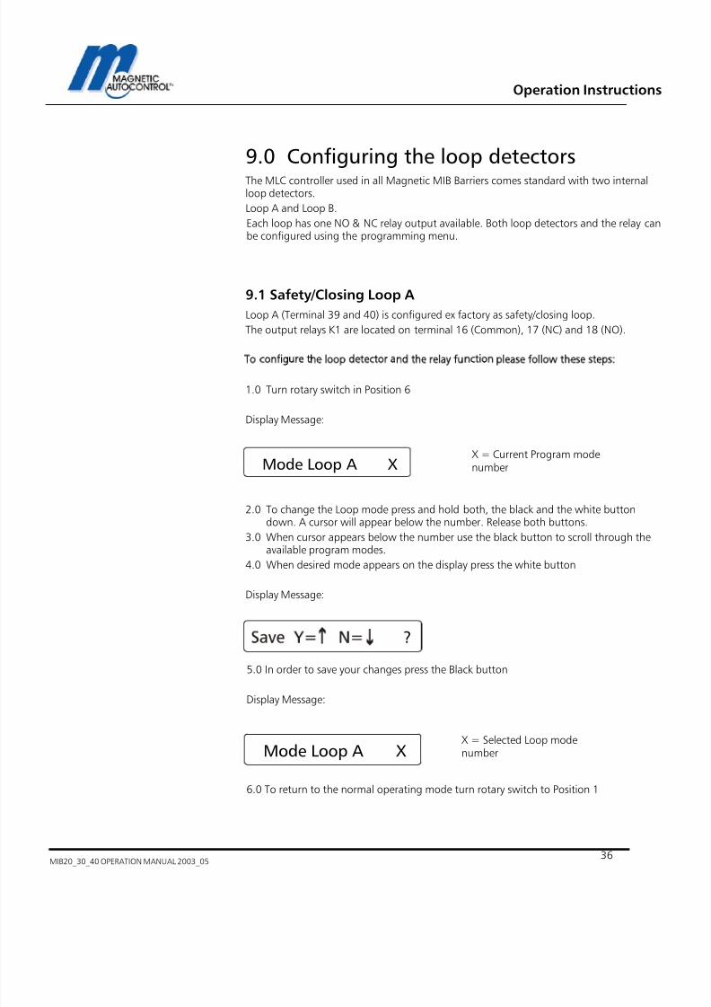
9.0 Configuring the loop detectorsThe MLC controller used in all Magnetic MIB Barriers comes standard with two internalloop detectors.
Loop A and Loop B.
Each loop has one NO & NC relay output available. Both loop detectors and the relay canbe configured using the programming menu.
9.1 Safety/Closing Loop A
Loop A (Terminal 39 and 40) is configured ex factory as safety/closing loop.
The output relays K1 are located on terminal 16 (Common), 17 (NC) and 18 (NO).
To configure the loop detector and the relay function please follow these steps:
1.0 Turn rotary switch in Position 6
Display Message:
2.0 To change the Loop mode press and hold both, the black and the white button
down. A cursor will appear below the number. Release both buttons.3.0 When cursor appears below the number use the black button to scroll through theavailable program modes.
4.0 When desired mode appears on the display press the white button
Display Message:
5.0 In order to save your changes press the Black button
Display Message:
6.0 To return to the normal operating mode turn rotary switch to Position 1
Mode Loop A X
X = Current Program modenumber
X = Selected Loop modenumberMode Loop A X

7/22/2019 Mib20!30!40 Operation Manual 2003_05
http://slidepdf.com/reader/full/mib203040-operation-manual-200305 37/106
Operation Instructions
MIB20_30_40 OPERATION MANUAL 2003_05 - 37 -
9.2 Loop A Mode function
9.2.1 Detector Mode A
Mode Internal function Function K1
0 Loop is disabled Maintained contact when gate isfull open
1 Safety / closes barrier (Program5-8)
Maintained contact when gate isfull open
2 Safety / closes barrier (Program5-8)
Maintained contact when Loop Ais occupied
3 Safety / closes barrier (Program5-8)
Pulse signal when vehicle entersLoop A
4 Safety / closes barrier (Program
5-8)
Pulse signal when vehicle leaves
Loop A5 Safety / closes barrier (Program
5-8)Pulse signal with directional logic
(see below)
6 Safety / closes barrier (Program5-8)
Pulse signal with directional logic(see below)
7 Safety / closes barrier (Program5-8)
Maintained Signal with directionallogic (see below)
8 Safety / closes barrier (Program5-8)
Maintained Signal with directionallogic (see below)
9 No safety/closing function Maintained contact when Loop Ais occupied
9.2.2 Directional Logic Loop A
In Loop Modes 5,6,7 and 8 the relays corresponding to Loop A and Loop B can be set toprovide pulses or maintained contacts depending in what direction the vehicle travels.Relay K1 (Terminal 16/17/18) respond to Loop A.
Loop A Mode 5
Note:For the directional logic to function, Loop A and Loop B, it must be assured that thevehicles that use this lane trigger both loops at the same time. If this cannot be achieveda special input counting software is required. In that case please call for further details.
Vehicle travels from Loop B to Loop A. A300mS pulse will be issued on relay K1when vehicle drives on Loop B and thenLoop A.Logic:B/BA (pulse)
Loop B Loop A
Relay K 10.3 sec Pulse
7/22/2019 Mib20!30!40 Operation Manual 2003_05
http://slidepdf.com/reader/full/mib203040-operation-manual-200305 38/106
Operation Instructions
MIB20_30_40 OPERATION MANUAL 2003_0538
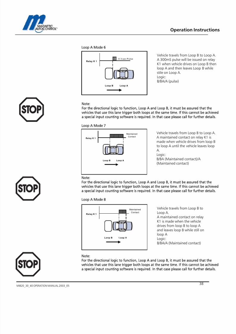
Loop A Mode 6
Note:For the directional logic to function, Loop A and Loop B, it must be assured that thevehicles that use this lane trigger both loops at the same time. If this cannot be achieved
a special input counting software is required. In that case please call for further details.
Loop A Mode 7
Note:For the directional logic to function, Loop A and Loop B, it must be assured that thevehicles that use this lane trigger both loops at the same time. If this cannot be achieveda special input counting software is required. In that case please call for further details.
Loop A Mode 8
Note:For the directional logic to function, Loop A and Loop B, it must be assured that thevehicles that use this lane trigger both loops at the same time. If this cannot be achieveda special input counting software is required. In that case please call for further details.
Vehicle travels from Loop B to Loop A.
A 300mS pulse will be issued on relayK1 when vehicle drives on Loop B thenloop A and then leaves Loop B whilestile on Loop A.Logic:B/BA/A (pulse)
Vehicle travels from Loop B to Loop A.A maintained contact on relay K1 ismade when vehicle drives from loop Bto loop A until the vehicle leaves loopA.Logic:B/BA (Maintained contact)/A(Maintained contact)
Loop B Loop A
Relay K 1
Maintained
Contact
Vehicle travels from Loop B toLoop A.A maintained contact on relayK1 is made when the vehicledrives from loop B to loop Aand leaves loop B while still on
loop ALogic:B/BA/A (Maintained contact)
Loop B Loop A
Relay K 1
Maintained
Contact
Loop B Loop A
Relay K 10.3 sec Pulse
7/22/2019 Mib20!30!40 Operation Manual 2003_05
http://slidepdf.com/reader/full/mib203040-operation-manual-200305 39/106
Operation Instructions
MIB20_30_40 OPERATION MANUAL 2003_05 - 39 -
?
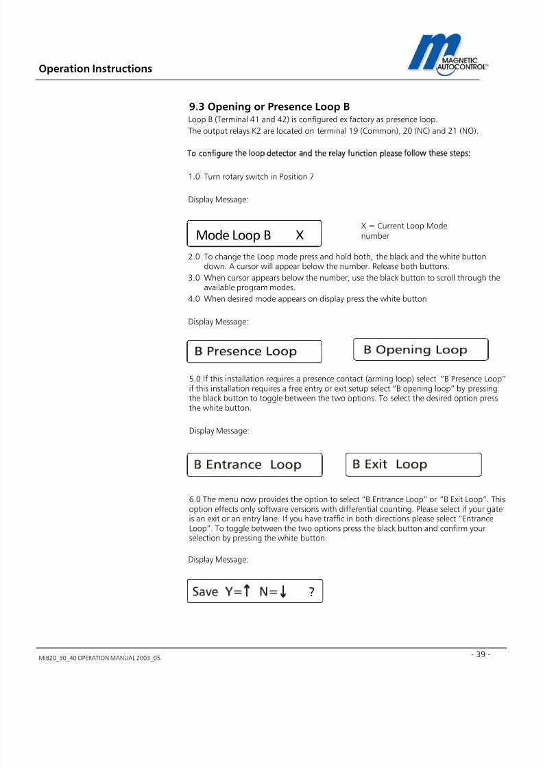
9.3 Opening or Presence Loop B
Loop B (Terminal 41 and 42) is configured ex factory as presence loop.
The output relays K2 are located on terminal 19 (Common), 20 (NC) and 21 (NO).
To configure the loop detector and the relay function please follow these steps:
1.0 Turn rotary switch in Position 7
Display Message:
2.0 To change the Loop mode press and hold both, the black and the white button
down. A cursor will appear below the number. Release both buttons.3.0 When cursor appears below the number, use the black button to scroll through the
available program modes.
4.0 When desired mode appears on display press the white button
Display Message:
5.0 If this installation requires a presence contact (arming loop) select “B Presence Loop”if this installation requires a free entry or exit setup select “B opening loop” by pressingthe black button to toggle between the two options. To select the desired option pressthe white button.
Display Message:
6.0 The menu now provides the option to select “B Entrance Loop” or “B Exit Loop”. Thisoption effects only software versions with differential counting. Please select if your gateis an exit or an entry lane. If you have traffic in both directions please select “EntranceLoop”. To toggle between the two options press the black button and confirm your
selection by pressing the white button.
Display Message:
X = Current Loop ModenumberMode Loop B X
7/22/2019 Mib20!30!40 Operation Manual 2003_05
http://slidepdf.com/reader/full/mib203040-operation-manual-200305 40/106
Operation Instructions
MIB20_30_40 OPERATION MANUAL 2003_0540
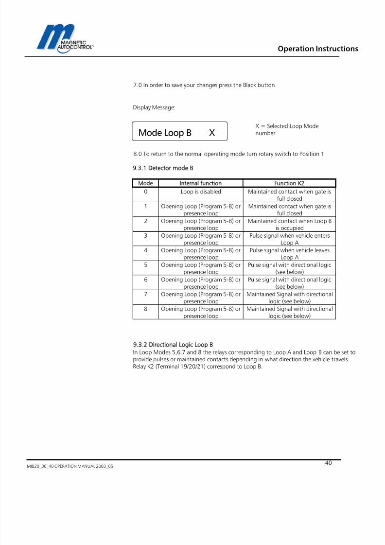
7.0 In order to save your changes press the Black button
Display Message:
8.0 To return to the normal operating mode turn rotary switch to Position 1
9.3.1 Detector mode B
Mode Internal function Function K2
0 Loop is disabled Maintained contact when gate isfull closed
1 Opening Loop (Program 5-8) orpresence loop
Maintained contact when gate isfull closed
2 Opening Loop (Program 5-8) orpresence loop
Maintained contact when Loop Bis occupied
3 Opening Loop (Program 5-8) orpresence loop
Pulse signal when vehicle entersLoop A
4 Opening Loop (Program 5-8) orpresence loop
Pulse signal when vehicle leavesLoop A
5 Opening Loop (Program 5-8) orpresence loop
Pulse signal with directional logic(see below)
6 Opening Loop (Program 5-8) or
presence loop
Pulse signal with directional logic
(see below)7 Opening Loop (Program 5-8) or
presence loopMaintained Signal with directional
logic (see below)
8 Opening Loop (Program 5-8) orpresence loop
Maintained Signal with directionallogic (see below)
9.3.2 Directional Logic Loop BIn Loop Modes 5,6,7 and 8 the relays corresponding to Loop A and Loop B can be set toprovide pulses or maintained contacts depending in what direction the vehicle travels.Relay K2 (Terminal 19/20/21) correspond to Loop B.
X = Selected Loop ModenumberMode Loop B X

7/22/2019 Mib20!30!40 Operation Manual 2003_05
http://slidepdf.com/reader/full/mib203040-operation-manual-200305 41/106
Operation Instructions
MIB20_30_40 OPERATION MANUAL 2003_05 - 41 -
Loop B Mode 5
Note:For the directional logic to function, Loop A and Loop B, it must be assured that thevehicles that use this lane trigger both loops at the same time. If this cannot be achieveda special input counting software is required. In that case please call for further details.
Loop B Mode 6
Note:For the directional logic to function, Loop A and Loop B, it must be assured that thevehicles that use this lane trigger both loops at the same time. If this cannot be achieveda special input counting software is required. In that case please call for further details.
Loop B Mode 7
Note:For the directional logic to function, Loop A and Loop B, it must be assured that thevehicles that use this lane trigger both loops at the same time. If this cannot be achieveda special input counting software is required. In that case please call for further details.
Vehicle travels from Loop A toLoop B. A 300mS pulse will beissued on relay K2 when vehicledrives from Loop A to Loop Band leaves Loop A.Logic:A/AB/B (pulse)
Vehicle travels from Loop A toLoop B.A 300mS pulse will be issuedon relay K2 when vehicle drivesfrom Loop A to loop B whilestill on Loop A.Logic:A/AB(pulse)
Loop A Loop B
Relay K 2
Maintain
Contact
Vehicle travels from Loop A toLoop B.A maintained contact on relayK2 is made when the vehicledrives from loop A to loop Band leaves loop A while still onloop B.
A/AB/B (Maintained Contact)
Loop A Loop B
Relay K 20.3 sec Pulse
Loop A Loop B
Relay K 20.3 sec Pulse

7/22/2019 Mib20!30!40 Operation Manual 2003_05
http://slidepdf.com/reader/full/mib203040-operation-manual-200305 42/106
Operation Instructions
MIB20_30_40 OPERATION MANUAL 2003_0542
Loop B Mode 8
Note:For the directional logic to function, Loop A and Loop B, it must be assured that thevehicles that use this lane trigger both loops at the same time. If this cannot be achieveda special input counting software is required. In that case please call for further details.
10.0 Loop FrequencyThe internal loop detectors are designed using the Multiplex technology. This means thatthe loops connected to one MLC controller cannot interfere with each other. Only loopsconnected to other detectors can interfere with the loops connected to anothercontroller. Many factors determine loop frequency, including wire size, wire length, thenumber of turns, lead length, and insulation.If multiple barriers are installed in close proximity (within 20 feet) it might be necessaryto switch individual MLC controllers to low or high frequency. To determine the necessity
of a frequency change the MLC controller displays the current frequency of the installedinduction loops. The MLC controller operates at a frequency between 10-100khz. Thecurrent loop frequency can be viewed by turning the rotary switch in position 8.
10.1 How to view the loop frequency:
1.0 Turn the rotary switch to position 8.
Display message:
2.0 To toggle between Loop A and Loop B press the white button.
3.0 To return to the normal operating mode turn rotary switch to Position 1
Note:
If Loop A or Loop B is not activated the display shows “OFF”.
The same message appears if the loop frequency is outside the operating limits
(10-100khz), not connected properly or when the loop wires are broken.
Loop A Loop B
Relay K 2
Maintained
Contact
Vehicle travels from Loop A toLoop B.A maintained contact on relayK2 is made when the vehicledrives from loop A to loop Buntil leaving loop ALogic:A/AB (Maintained contact)/B(Maintained Contact)
X = Current Loop frequency

7/22/2019 Mib20!30!40 Operation Manual 2003_05
http://slidepdf.com/reader/full/mib203040-operation-manual-200305 43/106
Operation Instructions
MIB20_30_40 OPERATION MANUAL 2003_05 - 43 -
The frequency display can be used to determine what might be the cause of loop cross
talking and can also be used to prevent it from happening.The frequencies of two loops that use different detectors (not connected to the same
MLC controller) must be at least 3kHz (3000Hz) apart.
10.2 How to change the loop frequency:
The MLC controller has two DIP- switches located below terminal strip numbered 22-42.In order to reach the Dip- switches, remove the terminal strip. Follow the instructionsbelow to remove the terminal strip and change loop frequency.
1.0 Turn the main supply voltage off. There is no need to disconnect any of the control-wiring going to this terminal strip.
2.0 Unscrew the two Phillips head screws located on each end of the terminal strip (see
drawing below)
3.0 Pull the terminal strip up and remove it completely from the controller.
4.0 The two dipswitches are located on the right hand side (see drawing) below the
loop connector terminals.
DIP-
SWITCH
M1
IN1 IN2 IN3 IN4 IN5
L NC C
0V 0V
M2 M3
A B
654321 16151413121110987 2120191817
K1 K2
bk rd
wh
00
M1
IN1 IN2 IN3 IN4 IN5
L N
C C
0V 0V
M2 M3
272625242322 37363534333231302928 4241403938
A B
654321 16151413121110987 2120191817
K1 K2
bk rd
wh
00
U n s c r e w t h e s e t w o P h i ll ip s h e a d
s c r e w s t o r e m o v e t h e t e r m i n a l
str ip

7/22/2019 Mib20!30!40 Operation Manual 2003_05
http://slidepdf.com/reader/full/mib203040-operation-manual-200305 44/106
Operation Instructions
MIB20_30_40 OPERATION MANUAL 2003_0544
5.0 You are now able to change the frequency of each individual loop to “High” or
“Low”. See drawing below for settings.
6.0 After changing the DIP- switch settings, replace the terminal strip, secure the Phillipshead screws, return the rotary switch to position 0, and turn the main power supplyon.
7.0 By moving the rotary switch to position 8 you can view the new frequency settingsof your loops.
Note:
Every change in loop frequency requires a controller reset. This can be done by simplyturning the power off and turning it back on or pushing both the black and the whitebutton and holding it until the controller resets (approx. 3sec)
11.0 Relay K1 OutputThe switching point of relay K1 can be set in relation to the barrier arm position. This canonly be done when Loop Mode A is set to “0”. The relay switching point can be set inrotary switch position B.
Follow these steps to change the switch position:
1. Turn the rotary switch to position BDisplay Message:
High
Low
L o o p
A
L o o p
B
1 - switch on XX
XX= Current switch position setting whenbarrier goes up.
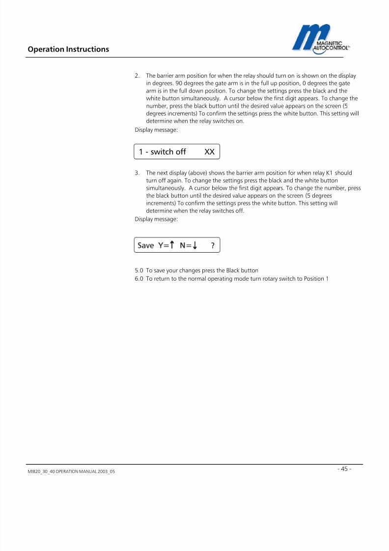
7/22/2019 Mib20!30!40 Operation Manual 2003_05
http://slidepdf.com/reader/full/mib203040-operation-manual-200305 45/106
Operation Instructions
MIB20_30_40 OPERATION MANUAL 2003_05 - 45 -
2. The barrier arm position for when the relay should turn on is shown on the display
in degrees. 90 degrees the gate arm is in the full up position, 0 degrees the gate
arm is in the full down position. To change the settings press the black and the
white button simultaneously. A cursor below the first digit appears. To change thenumber, press the black button until the desired value appears on the screen (5
degrees increments) To confirm the settings press the white button. This setting will
determine when the relay switches on.
Display message:
3. The next display (above) shows the barrier arm position for when relay K1 should
turn off again. To change the settings press the black and the white button
simultaneously. A cursor below the first digit appears. To change the number, press
the black button until the desired value appears on the screen (5 degrees
increments) To confirm the settings press the white button. This setting will
determine when the relay switches off.
Display message:
5.0 To save your changes press the Black button
6.0 To return to the normal operating mode turn rotary switch to Position 1
1 - switch off XX
?
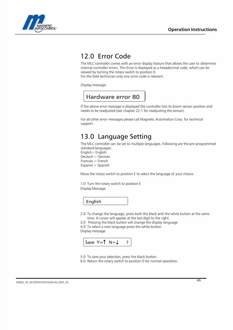
7/22/2019 Mib20!30!40 Operation Manual 2003_05
http://slidepdf.com/reader/full/mib203040-operation-manual-200305 46/106
Operation Instructions
MIB20_30_40 OPERATION MANUAL 2003_0546
12.0 Error CodeThe MLC controller comes with an error display feature that allows the user to determineinternal controller errors. This Error is displayed as a hexadecimal code, which can beviewed by turning the rotary switch to position D.For the field technician only one error code is relevant:
Display message:
If the above error message is displayed the controller lost its boom sensor position andneeds to be readjusted (see chapter 22.1 for readjusting the sensor).
For all other error messages please call Magnetic Automation Corp. for technicalsupport.
13.0 Language SettingThe MLC controller can be set to multiple languages. Following are the pre-programmedstandard languages:English= EnglishDeutsch = GermanFrancais = FrenchEspanol = Spanish
Move the rotary switch to position E to select the language of your choice.
1.0 Turn the rotary switch to position E
Display Message:
2.0 To change the language, press both the black and the white button at the sametime. A cursor will appear at the last digit to the right.
3.0 Pressing the black button will change the display language.4.0 To select a new language press the white button
Display message:
5.0 To save your selection, press the black button.6.0 Return the rotary switch to position 0 for normal operation.
?

7/22/2019 Mib20!30!40 Operation Manual 2003_05
http://slidepdf.com/reader/full/mib203040-operation-manual-200305 47/106
Operation Instructions
MIB20_30_40 OPERATION MANUAL 2003_05 - 47 -
14.0 Default SettingsThe controller can be reset to original manufacturer default settings. By doing so all
programmed settings are erased. To set the controller to its original manufacturer settingturn the rotary switch to position F.Press the black and white button, release.Press the black button to set the controller to default.

7/22/2019 Mib20!30!40 Operation Manual 2003_05
http://slidepdf.com/reader/full/mib203040-operation-manual-200305 48/106
Operation Instructions
MIB20_30_40 OPERATION MANUAL 2003_0548
15.0 Extended Menu settings:Note:To access the extended operating menu, the black button must be pressed while therotary selector switch is turned to the required position.
Safety Angle:Disabling ofsafety device indown positionPos. _1
Adjustment of the angle (boom position) at which thesafety device (induction loop, light beam etc.) should bedisabled before the boom reaches the complete downposition.
Operating hoursPos. _2
Displays the total time in hours the barrier was turned on.Timer is not resetable.
Operating cyclecounter.
Pos. _3
Displays the total cycle count of the barrier. This counter isindexed every ten (10) cycles, and is not resetable.
Brake settings.Pos. _4
This enables you to read the current brake settings, whichmight be helpful to determine gate failures.
Not availablePos. _5,6,7,8,A
These positions do not have any function.
Brake fine tuningPos. _B
This position allows you to fine tune the brake settings incase the brake might not be satisfactory.Positive numbers: Gate will brake soonerNegative numbers: The gate will brake later.
ResetPos. _C
Choice of resetting behavior after the power is restored tothe gate. Signal Reset = The gate will reset after the firstInput is made.
Auto Reset = the gate will reset (close) when power isrestored.
Test ModePos. D
This can be used to cycle the gate automatically.
MotorPos. E
This menu can be used to adjust the potentiometer.

7/22/2019 Mib20!30!40 Operation Manual 2003_05
http://slidepdf.com/reader/full/mib203040-operation-manual-200305 49/106
Operation Instructions
MIB20_30_40 OPERATION MANUAL 2003_05 - 49 -
15.1 Adjusting the safety angle:
This setting allows the user to adjust the boom position in which the controller disablesthe safety devices. This setting allows the user to increase the safety of the operation orprevent tail gating from happening. To increase safety, the cut off angle is smaller; toprevent tail gating, the cut of angle is higher (i.e. the safety device is disabled sooner). Todisable the safety cut off sooner to prevent tailgating will also increase the possibilitythat vehicles are being hit by the gate arm. This angle is adjustable between 10°- 80° in5° increments. The down position equals 0° and the complete up position 90°. Tochange the setting follow steps below.
1.0 Press and hold the black button while turning the rotary switch to position 1
Display Message:
2.0 Press the black and the white button simultaneously. A cursor below the first digit
appears. To change the number, press the black button. To confirm the settings
press the white button.
Display Message:
3.0 Press the black button to save the changes.
4.0 Return the rotary switch to position 0 for normal operation.
X = Current setting
?
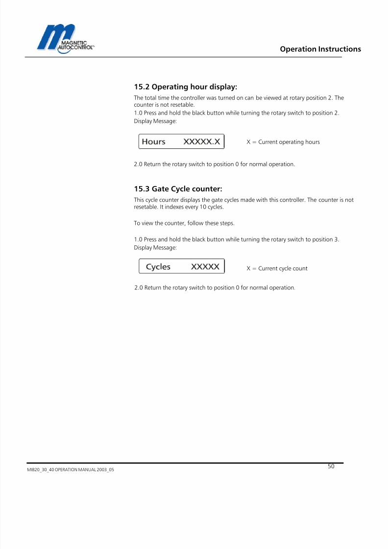
7/22/2019 Mib20!30!40 Operation Manual 2003_05
http://slidepdf.com/reader/full/mib203040-operation-manual-200305 50/106
Operation Instructions
MIB20_30_40 OPERATION MANUAL 2003_0550
15.2 Operating hour display:
The total time the controller was turned on can be viewed at rotary position 2. Thecounter is not resetable.
1.0 Press and hold the black button while turning the rotary switch to position 2.
Display Message:
2.0 Return the rotary switch to position 0 for normal operation.
15.3 Gate Cycle counter:This cycle counter displays the gate cycles made with this controller. The counter is notresetable. It indexes every 10 cycles.
To view the counter, follow these steps.
1.0 Press and hold the black button while turning the rotary switch to position 3.
Display Message:
2.0 Return the rotary switch to position 0 for normal operation.
X = Current operating hours
X = Current cycle count

7/22/2019 Mib20!30!40 Operation Manual 2003_05
http://slidepdf.com/reader/full/mib203040-operation-manual-200305 51/106
Operation Instructions
MIB20_30_40 OPERATION MANUAL 2003_05 - 51 -
15.4 Reading the Brake Points:
All MIB barriers self adjust to the optimal brake points depending on boom length,boom weight, Barrier model and spring adjustment. The brake points must be within apre-programmed range. Following table shows the range for each of the barrier models:
Barrier Model Brake Point Up Brake Point down
MIB20 50Hz 100-220 80-170
MIB20 60Hz 50-180 70-170
MIB30 50Hz 40-240 60-280
MIB30 60Hz 80-290 90-280
MIB40 50Hz 40-150 60-180
MIB40 60Hz 70-150 50-200
To view the current brake points follow these steps:
1.0 Press and hold the black button while turning the rotary switch to position 4.
Display Message:
2.0 Return the rotary switch to position 0 for normal operation
Note:
Comparing the displayed brake points with the brake point range of the individual
barrier model can determine possible malfunctioning of the barrier.
If the brake points are out of range please follow the instructions in chapter 22.1.
15.5 Resetting the barrier after power failure:
The MLC controller can be set to two different resets after a power failure.
Ex factory the setting is “Signal Reset”.
Signal Reset:
If the barrier is in the fully closed position after the power is restored the controller willaccept all inputs immediately after booting the software.
If the barrier is not in the fully closed position the gate will open and remain open untilthe following occurs:
1. Reset by pressing the black and the white button simultaneously for approx 2sec.
2. Closing input on IN3
3. Passing through the safety/closing device (external or internal).
XXX = Current brake pointgate position UP
YYY = Current brake pointgate position DOWN
XXX YYY

7/22/2019 Mib20!30!40 Operation Manual 2003_05
http://slidepdf.com/reader/full/mib203040-operation-manual-200305 52/106
Operation Instructions
MIB20_30_40 OPERATION MANUAL 2003_0552
Before any of the above steps are taken the display will show the following:
Any of the above actions will reset the controller to the normal operation mode.
The other reset option is
Auto Reset:After the power is restored the barrier reacts to any activated input independent of thebarrier arm position. If no opening input is activated and no object is in the safety zonethe barrier will close.
Please follow these steps to select the reset mode:
1.0 Press and hold the black button while turning the rotary switch to position C.
Display Message:
2.0 Press the black and the white button simultaneously. A cursor appears on the right
hand side of the display. To change the setting, press the black button. To confirm the
settings press the white button.
Display message:
3.0 Press the black button to save the changes.
4.0 Return the rotary switch to position 0 for normal operation.
15.6 Test Mode
The MLC controller offers the feature to run the barrier in a test mode without having toinstall an open close timer or other equipment. During this test mode the barrier willopen and close continuously. This can be used for equipment demonstration or testing.
Please follow these steps to set the controller in test mode:
1.0 Press and hold the black button while turning the rotary switch to position D.
Display Message:
The “RESET REQUESTED” displayflashes in a 1sec. Interval.
?

7/22/2019 Mib20!30!40 Operation Manual 2003_05
http://slidepdf.com/reader/full/mib203040-operation-manual-200305 53/106
Operation Instructions
MIB20_30_40 OPERATION MANUAL 2003_05 - 53 -
2.0 To change to Test Mode press the black and white button simultaneously.Display Message:
3.0 Release both buttons. The number has now changed to 9, which symbols the testmode is set.
4.0 Return the rotary switch to position 0
Display Message:
5.0 If no input is activated and no object is in the safety zone the barrier will now startto cycle up and down.
6.0 To return to the normal operation mode, simply turn the rotary switch to position 1and then back to position 0.
X= Current Program Mode setting
9= Test Mode
00

7/22/2019 Mib20!30!40 Operation Manual 2003_05
http://slidepdf.com/reader/full/mib203040-operation-manual-200305 54/106
Operation Instructions
MIB20_30_40 OPERATION MANUAL 2003_0554
16.0 Installing the Induction Loops
16.1 General induction loop functionality
The Loop detectors operate on the principle of inductance. The detector monitors aninsulated electrical wire, placed on or below the road surface (LOOP). Any metallicobject, such as a car, which passes through the field will absorb electromagnetic energyand simultaneously decrease the inductance and increase the resonant frequency of theloop. For most conventional installations, when the inductance or frequency changesbeyond a preset threshold in the detector electronics, the detector indicates that avehicle has been detected.Note:Only metallic objects can be detected. The loop frequency change depends on the sizeand form of the to be monitored object (i.e. car) not on the material mass, which doesnot influence the loop.
The micro controller system self adjusts to the connected loop. Many factors determineloop inductance, including wire size, wire length, the number of turns, lead length, andinsulation.Changes in loop inductance due to temperature or aging are automaticallycompensated.Detectors with multiple channels (i.e. dual channel) are monitored using the MULTIPLEXMETHOD, which eliminates the interference (cross-talk) between the loops connected tothis detector.
16.2 Loop Inductance
16.2.1 Inductance
Inductance is the resistance to the change of current flow. When a current is applied to aconductor (wire) a magnetic field is formed around the conductor (wire). If the currentsource is removed, the magnetic field collapses into the wire trying to maintain thecurrent flow. By winding several turns of the wire into a coil, the magnetic field isintensified which increases the inductance.
The loop inductance can be measured with an inductivity meter. The unit ofmeasurements is the Henry (h). The inductance depends on the loop perimeter andnumber of turns. A bigger loop with more turns has a higher Inductance.

7/22/2019 Mib20!30!40 Operation Manual 2003_05
http://slidepdf.com/reader/full/mib203040-operation-manual-200305 55/106
Operation Instructions
MIB20_30_40 OPERATION MANUAL 2003_05 - 55 -
16.2.2 Vehicle detection
When a vehicle enters the loop the body and frame provide a conductive path for themagnetic field; causing a loading effect, which in turn causes the loop inductance todecrease. The decreased inductance causes the resonant frequency to increase from thenominal value. If the frequency change exceeds the threshold set by the sensitivitysetting, the detector module will output a detect signal.
There has been a misconception that an inductive loop requires a mass of metal fordetection. Placing a single wire around the perimeter of the loop and shorting the endstogether will quickly disprove the misconception. The single wire forming a shorted turnprovides a current path for the magnetic field; thus causing a loading effect similar tothat of a vehicle. The shorted turn effect of the single wire coil in the proximity of theloop acts much like a shorted turn secondary of a transformer.
16.2.3 Wire Turns required for loops
The Inductive loop detectors will tune from 70 µH to 500 µH (µH = microHenry). It ispreferable that the loop and lead-in have a minimum of approximately 70 µH forstability. The loop inductance should be equal to or greater than the lead-in inductance.If the inductance of the loop exceeds the requirements above, a proper functioning ofthe detector cannot be guaranteed.
The loop inductance also influences the loop sensitivity. The best results are between 100and 300 µH.

7/22/2019 Mib20!30!40 Operation Manual 2003_05
http://slidepdf.com/reader/full/mib203040-operation-manual-200305 56/106
Operation Instructions
MIB20_30_40 OPERATION MANUAL 2003_0556
16.2.4 Loop Inductance calculations
The number of turns required in the loop is dependent on the loop size. The loopinductance can be calculated as follows:
L = P/4 (t² +t)
L = Inductance (micro Henries)P = Perimeter (feet)t = Number of turns
The formula can be simplified to: L = PK Substituting a constant K for (t² +t)/4
Filling in the Number of Turns and calculating K:
Note:Use the highlighted values to determine the number of turns required. ALWAYS USE ATLEAST 2 TURNS. In addition to the above result the inductivity of the wires used in theloop must be added. Depending on the used wire it is between 1 – 1.5 µH per everythree (3) feet.
Example: 4’ x 8’ with 4 turnsL = PKP = 4’+4’+8’+8’= 24 feetK = 5.0L = 24 x 5.0L = 120 micro henries
Number Of Turns(t)
k (constant)k= (t2 + t)/4
2 1.5
3 3
4 5
5 7.5
6 11.5
7 14
NUMBER OF TURNS
2 3 4 5 6 7
10 15 30 50 75 115 140
20 30 60 100 150 230 280
30 45 90 150 225 345 420
40 60 120 200 300 460 560
50 75 150 250 275 575 700
60 90 180 300 450 690 840
70 105 210 350 525 805 980
80 120 240 400 600 920 1120
90 135 270 450 675 1035 1260
P E R I M E T E R F E E T
100 150 300 500 750 1150 1400
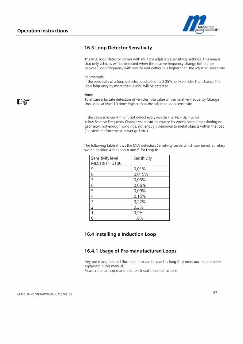
7/22/2019 Mib20!30!40 Operation Manual 2003_05
http://slidepdf.com/reader/full/mib203040-operation-manual-200305 57/106
Operation Instructions
MIB20_30_40 OPERATION MANUAL 2003_05 - 57 -
16.3 Loop Detector Sensitivity
The MLC loop detector comes with multiple adjustable sensitivity settings. This meansthat only vehicles will be detected when the relative frequency change (differencebetween loop frequency with vehicle and without) is higher than the adjusted sensitivity.
For example:If the sensitivity of a loop detector is adjusted to 0.05%, only vehicles that change theloop frequency by more than 0.05% will be detected.
Note:To ensure a failsafe detection of vehicles, the value of the Relative Frequency Changeshould be at least 10 times higher than the adjusted loop sensitivity
If the value is lower it might not detect every vehicle (i.e. Pick-Up trucks).A low Relative Frequency Change value can be caused by wrong loop dimensioning orgeometry, not enough windings, not enough clearance to metal objects within the road(i.e. steel reinforcement, sewer grill etc.).
The following table shows the MLC detectors Sensitivity Levels which can be set at rotaryswitch position 4 for Loop A and 5 for Loop B:
16.4 Installing a Induction Loop
16.4.1 Usage of Pre-manufactured Loops
Any pre-manufactured (formed) loop can be used as long they meet our requirementsexplained in this manual.Please refer to loop manufacturers Installation Instructions.
Sensitivity levelMLC10/11-U100
Sensitivity
9 0,01%
8 0,015%
7 0,03%6 0,06%
5 0,09%
4 0,15%
3 0,22%
2 0,3%
1 0,9%
0 1,8%
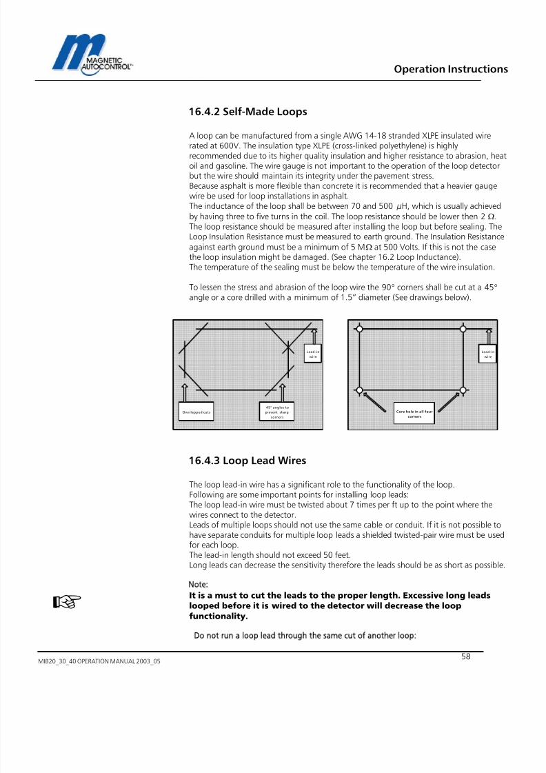
7/22/2019 Mib20!30!40 Operation Manual 2003_05
http://slidepdf.com/reader/full/mib203040-operation-manual-200305 58/106
Operation Instructions
MIB20_30_40 OPERATION MANUAL 2003_0558
16.4.2 Self-Made Loops
A loop can be manufactured from a single AWG 14-18 stranded XLPE insulated wirerated at 600V. The insulation type XLPE (cross-linked polyethylene) is highlyrecommended due to its higher quality insulation and higher resistance to abrasion, heatoil and gasoline. The wire gauge is not important to the operation of the loop detectorbut the wire should maintain its integrity under the pavement stress.Because asphalt is more flexible than concrete it is recommended that a heavier gaugewire be used for loop installations in asphalt.The inductance of the loop shall be between 70 and 500 µH, which is usually achievedby having three to five turns in the coil. The loop resistance should be lower then 2 Ω.The loop resistance should be measured after installing the loop but before sealing. TheLoop Insulation Resistance must be measured to earth ground. The Insulation Resistanceagainst earth ground must be a minimum of 5 MΩ at 500 Volts. If this is not the casethe loop insulation might be damaged. (See chapter 16.2 Loop Inductance).
The temperature of the sealing must be below the temperature of the wire insulation.
To lessen the stress and abrasion of the loop wire the 90° corners shall be cut at a 45° angle or a core drilled with a minimum of 1.5” diameter (See drawings below).
16.4.3 Loop Lead Wires
The loop lead-in wire has a significant role to the functionality of the loop.Following are some important points for installing loop leads:The loop lead-in wire must be twisted about 7 times per ft up to the point where thewires connect to the detector.Leads of multiple loops should not use the same cable or conduit. If it is not possible tohave separate conduits for multiple loop leads a shielded twisted-pair wire must be usedfor each loop.The lead-in length should not exceed 50 feet.Long leads can decrease the sensitivity therefore the leads should be as short as possible.
Note:It is a must to cut the leads to the proper length. Excessive long leadslooped before it is wired to the detector will decrease the loop
functionality.
Do not run a loop lead through the same cut of another loop:
Overlapped cuts
45° angles to
prevent sharp
corners
Lead-in
wire
Lead-in
wire
Core hole in all four
corners

7/22/2019 Mib20!30!40 Operation Manual 2003_05
http://slidepdf.com/reader/full/mib203040-operation-manual-200305 59/106
Operation Instructions
MIB20_30_40 OPERATION MANUAL 2003_05 - 59 -
16.4.4 How deep should the loop wires be installed?
The deeper the wires are below the road surface the more they are protected from roadsurface wear and the elements. The top wire should be a minimum of 1 inch below theroad surface.
Note:
Nonconductive materials such as concrete and asphalt will not influence the loop fields.Installing the loop one inch deeper (e.g. 3” depth not 2” depth) would have the sameresult as raising the vehicle one inch above the pavement surface.
L O O
P
L O O
P
L O O
P
WRONG CORRECT
L O O
P
Loop Sealant
Road
Mater ial
Loop W ires
14 AWG
XLPE
Insulation
1 . 5
0 "
m i n i m u m 1
"

7/22/2019 Mib20!30!40 Operation Manual 2003_05
http://slidepdf.com/reader/full/mib203040-operation-manual-200305 60/106
Operation Instructions
MIB20_30_40 OPERATION MANUAL 2003_0560
16.4.5 Loop distance from objects:
A minimum distance of 1ft between the loop and all metal objects (steel reinforcements,sewer grill etc.) must be kept. If this is not the case the loop sensitivity can decreasesignificantly and a proper functioning of the loop cannot be guaranteed.The loop and loop leads must not be installed near to any underground high voltagecables.The distance between loops and barrier housings or barrier arms should be a minimumof 10”.The following rule should be observed:
The longer the loop, the greater the spacing must be between the gate and the loop.
Following is a typical installation that shows how the loops should be installed. (seebelow).
T I M
Loop B
Loop A 1 . 5
'
1 . 5
'
6'
3 '
6' M a x . 6 '
1'
9'6"
G a t e
T r a f f i c
F l o w
1'-6"

7/22/2019 Mib20!30!40 Operation Manual 2003_05
http://slidepdf.com/reader/full/mib203040-operation-manual-200305 61/106
Operation Instructions
MIB20_30_40 OPERATION MANUAL 2003_05 - 61 -
17.0 Commissioning
17.1 Commissioning procedure
Once the barrier has been installed, the barrier boom attached and all electrical wiring
work (including the installation of induction loops) have been completed, according to
the instructions; the barrier can be put into operation.To avoid the risk of injury and damage arising from any unintentional barrier movementsduring initial operations, all persons and objects should be kept clear of the barrier.
17.2 Messages displayed during the start-up routine
The following messages are displayed during the controller start-up routine:
1. Display message:
1. Display message:
2. Display Message:
4. Display Message
5. Display Message:
6. Display Message:
Hard A- Hardware version ABoot 0002 = Softwareversion 0002
MLC10-100 = Controller TypeS240008 = Software Parameter
0009.0003 = Software Version00 = Parameter Version
MIB30 = Barrier Model60Hz = Voltage, frequency
00
See chapter 4.2 Displayinformation
7/22/2019 Mib20!30!40 Operation Manual 2003_05
http://slidepdf.com/reader/full/mib203040-operation-manual-200305 62/106
Operation Instructions
MIB20_30_40 OPERATION MANUAL 2003_0562
Note: Ex factory the barrier is shipped with the reset function as “SIGNAL RESET” (see chapter14.5 RESETTING THE BARRIER). After resetting the controller the barrier is now fullyfunctioning.
Please use the wiring diagrams displayed in chapter 5.0 PROGRAMMING MODES forInput wiring.
17.3 Standard Configuration:
Following are the standard controller configuration ex-factory:
17.3.1 Parking or access control configuration:Program Mode: 7 see chapter 5.1.7Loop A Sensitivity: 5 see chapter 8.0 and 15.3Loop B Sensitivity: 5 see chapter 8.0 and 15.3Loop Mode A: 2 see chapter 9.0Loop Mode B: 2 presence see chapter 9.0Safety Angle: 15° see chapter 15.1
17.3.2 Toll road application:
Program Mode: 4 see chapter 5.1.7
Hold Open Time: 35sec. see chapter 7.0
Loop A Sensitivity: 5 see chapter 8.0 and 15.3Loop B Sensitivity: 5 see chapter 8.0 and 15.3Loop Mode A: 0 see chapter 9.0Loop Mode B: 0 see chapter 9.0
Safety Angle: 15° see chapter 15.1
Note:If your installation requires different setting please follow the instructions in thecorresponding chapters.

7/22/2019 Mib20!30!40 Operation Manual 2003_05
http://slidepdf.com/reader/full/mib203040-operation-manual-200305 63/106
Operation Instructions
MIB20_30_40 OPERATION MANUAL 2003_05 - 63 -
18.0 Installation Example:
18.1 Free exit or entry configuration:
For a free entry or exit application please follow these steps:
1.0 Program Mode setting:
Mode 5, 6, 7 and 8 will work as free exit or entry application, depending on theapplication, set the mode accordingly. Please read chapter 5.1.5, 5.1.6,5.1.7 and 5.1.8for details.
Typical is Program Mode 5, which will close after the adjustable hold open timer elapsesif no vehicle passed through the safety/closing loop. If this installation requires that thegate should stay up if no vehicle passes through the safety/closing loop then chooseProgram Mode 7.
2.0 Loop Mode A setting:
Depending on the installation requirements, set Loop Mode A to meet thosespecifications. Please read chapter 9.0 for further details.
Typical is Loop Mode 2, which issues a potential free maintained contact on relay K1when a car is on the Loop.
3.0 Loop Mode B setting:
Depending on the installation requirements, set Loop Mode B to meet thosespecifications. Please read chapter 9.3 for further details.
For free exit or entry Loop Mode B must be set to “OPENING LOOP”. The output relay istypically set to 2 to receive a potential free maintained output on relay K2 whenever avehicle is on the loop.
Typical is Loop Mode 2, which issues a maintained potential free contact whenever avehicle is on the loop.
4.0 Hold Open Timer setting:
If this installation requires that the gate closes automatically after receiving an openingcommand without a vehicle passing through the safety closing zone, set Program Modeto 5 or 6 and set the hold-open timer according to your requirements. Please readchapter 7.0 for further details
Typical hold open timer setting is 35sec.
Note:
After all settings are done, return the rotary switch to position 0 for normal operation.
The barrier is now in full operation mode.

7/22/2019 Mib20!30!40 Operation Manual 2003_05
http://slidepdf.com/reader/full/mib203040-operation-manual-200305 64/106
Operation Instructions
MIB20_30_40 OPERATION MANUAL 2003_0564
18.1.1 Free entry or exit Lane Layout
The drawing below shows a typical lane layout for a fee entry or exit application.
Loop B
Loop A 1 . 5
'
1 . 5
'
6'
3 '
6' M a
x . 6 '
1'
9'6"
G a t e
T r a f f i c
F l o w
1'-6"

7/22/2019 Mib20!30!40 Operation Manual 2003_05
http://slidepdf.com/reader/full/mib203040-operation-manual-200305 65/106
Operation Instructions
MIB20_30_40 OPERATION MANUAL 2003_05 - 65 -
18.1.2 Free entry or exit wiring diagram:
Below is a Free entry or exit lane wiring diagram with a device to open the barrier ifconfigured as free exit.
Boom
Sensor
Motor Program 5
Loop
A
M1
IN1 IN2 IN3 IN4 IN5
L NC C
0V 0V
M2 M3
272625242322 37363534333231302928 4241403938
A B
654321 16151413121110987 2120191817
K1 K2
bk rd
wh
00
1 0 m F C A P .
8 m F C A P .
Loop
B R e d
W h i t e
B l a c k
100V...250VAC
50/60Hz
Potential Free
relay outputs.
S a f e t y / c l o s i n g l o o p
O p e n i n g L o o p

7/22/2019 Mib20!30!40 Operation Manual 2003_05
http://slidepdf.com/reader/full/mib203040-operation-manual-200305 66/106
Operation Instructions
MIB20_30_40 OPERATION MANUAL 2003_0566
18.2 Entry or exit with access control:
For a access controlled entry or exit , do the following:
1.0 Program Mode setting:
Mode 5, 6, 7 and 8 will work for this application, depending on the application, set themode accordingly. Please read chapter 5.1.5, 5.1.6,5.1.7 and 5.1.8 for details.
Typical is Program Mode 7, which will remain open if no vehicle passed through thesafety/closing zone. If this installation requires that the gate should automatically close ifno vehicle passes through the safety/closing loop, choose Program Mode 5.
2.0 Loop Mode A setting:
Depending on the installation requirements set Loop Mode A to meet those
specifications. Please read chapter 9.0 for further details.Typical is Loop Mode 2, which issued a potential free maintained contact on relay K1when a car is on the Loop. This can be used to reset the access control equipment.
3.0 Loop Mode B setting:
In an access control application Loop B is used as presence (arming) loop. Please readchapter 9.3 for further details.
To arm the access control equipment when a vehicle is present set the Loop Mode to 2and “PRESENCE LOOP”. This will issue a potential free maintained contact at Relay K2whenever a vehicle is on the loop.
Typical is Loop Mode 2, which issues a maintained potential free contact at relay K2whenever a vehicle is on the loop.
4.0 Hold Open Timer setting:If this installation requires that the gate closes automatically after receiving an openingcommand without a vehicle passing through the safety closing zone, set Program Modeto 5 or 6 and set the hold-open timer according to your requirements. Please readchapter 7.0 for further details.
Typical hold open timer setting is 35sec.

7/22/2019 Mib20!30!40 Operation Manual 2003_05
http://slidepdf.com/reader/full/mib203040-operation-manual-200305 67/106
Operation Instructions
MIB20_30_40 OPERATION MANUAL 2003_05 - 67 -
18.2.1 Access Control Lane layout
The drawing below shows a typical lane layout for an access control entry or exit..
A c c e s s
C o n t r o l
Loop B
Loop A 1 . 5
'
1 . 5
'
6'
3 '
6' M a
x . 6 '
1'
9'6"
M I B *
B
a r r i e r
T r a f f i c
F l o w
1'-6"

7/22/2019 Mib20!30!40 Operation Manual 2003_05
http://slidepdf.com/reader/full/mib203040-operation-manual-200305 68/106
Operation Instructions
MIB20_30_40 OPERATION MANUAL 2003_0568
18.2.2 Access Control Lane wiring diagram
Below is an Access Control entry exit-wiring diagram.
Boom
Sensor
Motor Program 7
Loop
A
M1
IN1 IN2 IN3 IN4 IN5
L NC C
0V 0V
M2 M3
272625242322 37363534333231302928 4241403938
A B
654321 16151413121110987 2120191817
K1 K2
bk rd
wh
00
1 0 m F C A P .
8 m F C A P .
Loop
B R e d
W h i t e
B l a c k
100V...250VAC
50/60Hz
S a f e t y / C l o s i n g L o o p
P r e s e n c e / A r m i n g L o o p
K1= Loop A re lay
output
K2= Presence /
arming loop
output

7/22/2019 Mib20!30!40 Operation Manual 2003_05
http://slidepdf.com/reader/full/mib203040-operation-manual-200305 69/106
Operation Instructions
MIB20_30_40 OPERATION MANUAL 2003_05 - 69 -
18.3 Access Control one direction free in/out other direction
1.0 Program Mode setting:
Mode 6 and 8 are recommended for this application. See chapter 5.1.6, and 5.1.8 fordetails. If the installation requires a presence loop to arm the access control equipmentan additional loop detector is required.
Typical is Program Mode 6, which will close after the adjustable hold open timer elapsesif no vehicle passed through the safety/closing loop. If this installation requires that thegate should stay up if no vehicle passes through the safety/closing loop choose ProgramMode 8.
2.0 Loop Mode A setting:
Loop A can only be used for the safety/closing function of the barrier.
Depending on the installation requirements, set Loop Mode A to meet thosespecifications. Please read chapter 9.0 for further details.
Typical is Loop Mode 2, which issues a potential free maintained contact on relay K1when a car is on the Loop.
3.0 Loop Mode B setting:
Depending on the installations requirements, set Loop Mode B to meet thosespecifications. Please read chapter 9.3 for further details.
For free exit or entry Loop Mode B must be set to “OPENING LOOP”. The output relay istypically set to 2 to receive a potential free maintained output on relay K2 whenever a
vehicle is on the loop.Typical is Loop Mode 2, which issues a maintained potential free contact whenever avehicle is on the loop.
4.0 Hold Open Timer setting:
If this installation requires that the gate closes automatically after receiving an openingcommand without a vehicle passing through the safety closing zone, set Program Modeto 6 and set the hold-open timer according to your requirements. Please read chapter7.0 for further details
Typical hold open timer setting is 35sec.
Note:
After all settings are done return the rotary switch to position 0 for normal operation.
The barrier is now in full operation mode.
If the installation requires a presence loop to arm the access control equipment anadditional loop detector is required.
No external wiring of the opening loop is required. The MLC controller handles theopening of the barrier internally.

7/22/2019 Mib20!30!40 Operation Manual 2003_05
http://slidepdf.com/reader/full/mib203040-operation-manual-200305 70/106
Operation Instructions
MIB20_30_40 OPERATION MANUAL 2003_0570
18.3.1 Access Control In Free Out Lane Layout
Drawing below shows a typical lane layout:
A c c
e s s
C o n
t r o l
Presence/
A rm ing Lo o p
Loop A 1 . 5
'
1 . 5
'
6'
3
'
6' M a x . 6
'
1'
9'6"
M I B *
B a r r i e r
T r a f f i c
F l o w
1'-6"
Loop B
M a x .
6 '
6'
3 '
T r a f f i c
F l o w
Separate standalone
loop detector

7/22/2019 Mib20!30!40 Operation Manual 2003_05
http://slidepdf.com/reader/full/mib203040-operation-manual-200305 71/106
Operation Instructions
MIB20_30_40 OPERATION MANUAL 2003_05 - 71 -
18.3.2 Access Control In Free Out Lane wiring diagram
Below is an Access Control “IN” free “OUT” wiring diagram:
Boom
Sensor
Motor Program 6
Loop
A
M1
IN1 IN2 IN3 IN4 IN5
L NC C
0V 0V
M2 M3
272625242322 37363534333231302928 4241403938
A B
654321 16151413121110987 2120191817
K1 K2
bk rd
wh
00
1 0 m
F C A P .
8 m F C A P .
Loop
B R e d
W h i t e
B l a c k
100V...250VAC
50/60Hz
Potential Free
relay outputs.
S a f e t y / c l o s i n g l o o p
O p e n i n g L o o p
A c c e s s P u l s e

7/22/2019 Mib20!30!40 Operation Manual 2003_05
http://slidepdf.com/reader/full/mib203040-operation-manual-200305 72/106
Operation Instructions
MIB20_30_40 OPERATION MANUAL 2003_0572
18.4 Master Slave configuration
In a master slave configuration, the master barrier controls the slave barrier. All accesscontrol wiring must go to the master barrier. An additional relay (see chapter 18.4.2) isrequired to achieve this function. The Master can be set in Mode 5 through 8 and theSlave barrier must be set to Mode 1.
1.0 Program Mode setting:
Master Barrier:
Mode 5, 6, 7 and 8 will work for this application. Depending on the application, set themode accordingly. Please read chapter 5.1.5, 5.1.6,5.1.7 and 5.1.8 for details.
Typical is Program Mode 7, which will remain open if no vehicle passed through thesafety/closing zone. If this installation requires that the gate should automatically close ifno vehicle passes through the safety/closing loop choose Program Mode 5 or 8.
Slave Barrier:
The slave barrier will only function in Program Mode 1.
2.0 Loop Mode A setting:
Master Barrier:
Depending on the installation requirements set Loop Mode A to meet thosespecifications. Please read chapter 9.0 for further details.
Typical is Loop Mode 2, which issues a potential free maintained contact on relay K1when a car is on the Loop. This can be used to reset the access control equipment.
Slave Barrier:
The Loop Mode A for the slave barrier should be 0 (= disabled). In wide lanes thatrequire more then one loop, connect them in series to the Master MLC controller.
3.0 Loop Mode B setting:
Master Barrier:
In an access control application Loop B is used as a presence (arming) loop. Please readchapter 9.3 for further details. If no presence (arming) loop is required set Loop Mode Bto 0.
To arm the access control equipment when a vehicle is present you must set the LoopMode to “2” and “PRESENCE LOOP”. This will issue a potential free maintained contacton relay K2 whenever a vehicle is on the loop.
In a free entry or exit application, Loop B must be set to “OPENING LOOP” and the Mode
depends on the application.Typical is Loop Mode 2, which issues a maintained potential free contact at relay K2whenever a vehicle is on the loop.
Slave Barrier:
Loop B must be set to 0 (= disabled).

7/22/2019 Mib20!30!40 Operation Manual 2003_05
http://slidepdf.com/reader/full/mib203040-operation-manual-200305 73/106
Operation Instructions
MIB20_30_40 OPERATION MANUAL 2003_05 - 73 -
4.0 Hold Open Timer setting:
Master Barrier:
If this installation requires that the gate closes automatically after receiving an openingcommand without a vehicle passing through the safety closing zone, set Program Modeto 5 or 6 and set the hold-open timer according your requirements. Please read chapter7.0 for further details.
Typical hold open timer setting is 35sec.
Slave Barrier:
The Slave barrier is operated in Program Mode 1, which doesn’t support this feature, butthe slave barrier will operate simultaneously with the Master barrier.

7/22/2019 Mib20!30!40 Operation Manual 2003_05
http://slidepdf.com/reader/full/mib203040-operation-manual-200305 74/106
Operation Instructions
MIB20_30_40 OPERATION MANUAL 2003_0574
18.4.1 Master/Slave Lane layout
Following is a drawing on how to layout the lane for a Master/Slave application
Loop B
Loop A 3 '
3 '
17.5'
6 '
17.5 '
M a x . 6 '
min.1'
38 '
M I B
*
B a r r i
e r
T r a f f i c
F l o w
1'-6"
MI B *
B
ar r i er
MASTER SLAVE
Loop B
Loop A
min.1'
min.1'
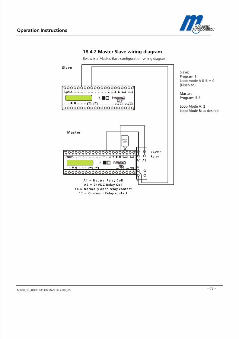
7/22/2019 Mib20!30!40 Operation Manual 2003_05
http://slidepdf.com/reader/full/mib203040-operation-manual-200305 75/106
Operation Instructions
MIB20_30_40 OPERATION MANUAL 2003_05 - 75 -
18.4.2 Master Slave wiring diagram
Below is a Master/Slave configuration-wiring diagram
M1
IN1 IN2 IN3 IN 4 IN5
L NC C
0V 0V
M2 M 3
272625242322 37363534333231302928 4241403938
A B
654321 16151413121110987 2120191817
K1 K2
A
B
C
D E
F 0 1 2 3
4
5
6 7
8 9
bk rd
wh
M1
IN1 IN 2 IN3 IN4 IN5
L NC C
0V 0V
M 2 M3
272625242322 37363534333231302928 4241403938
A B
654321 16151413121110987 2120191817
K1 K2
A
B
C
D E
F 0 1 2 3
4
5
6 7
8 9
bk rd
wh
Master
Slave
A2A1A1
11
14
24VDC
Relay
A1 = N eutr al Rela y Coil
A2 = 24VDC Rela y Coil
14 = Norm al ly open relay contact
11 = Comm on Relay contact

7/22/2019 Mib20!30!40 Operation Manual 2003_05
http://slidepdf.com/reader/full/mib203040-operation-manual-200305 76/106
Operation Instructions
MIB20_30_40 OPERATION MANUAL 2003_0576
18.5 Toll Road application:In most Toll-road applications, a lane controller controls the gate. Therefore the gatecontroller must respond to all inputs without being in an automatic mode. This isachieved by using Program Mode 4. See chapter 5.1.4 for details.
1.0 Program Mode setting:
Mode 4 is recommended for this application. See chapter 5.1.4 for details.
Mode 4 will open the barrier when an input on IN1 is made and will close when an inputon IN3 was made. The inputs shall be pulses of minimum 300msec..
2.0 Loop Mode A setting:
Loop A is set to Loop Mode 0 ex factory. Loop Mode 0 disables the loop detector andenables a potential free contact on relay K1 when the barrier is in the full up position.
See chapter 9.2 for details.
3.0 Loop Mode B setting:
Loop B is set to Loop Mode 0 ex factory. Loop Mode 0 disables the loop detector andenables a potential free contact on relay K2 when the barrier is in the full down position.
See chapter 9.3 for details.
4.0 Hold Open Timer setting:
The Hold open timer has no function in Mode 4.
Note:After all settings are done return the rotary switch to position 0 for normal operation.
The barrier is now in full operation mode.
If the installation requires a input override switch connect a normally open contact toinput IN2 of the controller. This input overrides all existing inputs.

7/22/2019 Mib20!30!40 Operation Manual 2003_05
http://slidepdf.com/reader/full/mib203040-operation-manual-200305 77/106
Operation Instructions
MIB20_30_40 OPERATION MANUAL 2003_05 - 77 -
18.5.1 Toll Road lane layout
Following is a typical toll road lane layout:
Loop A 1 . 5
'
1 . 5
'
6'1'
9'6"
M I B *
B a r r i e r
T r a f f i c
F l o w
1'-6"
Note:
Loop A is not
controlled by the
MIB* barrier.

7/22/2019 Mib20!30!40 Operation Manual 2003_05
http://slidepdf.com/reader/full/mib203040-operation-manual-200305 78/106
Operation Instructions
MIB20_30_40 OPERATION MANUAL 2003_0578
18.5.2 Toll Road wiring diagram
Following is a typical Toll application, wiring diagram:
Boom
Sensor
R e d
W h i t e
B l a c k
Motor
100V...250VAC
50/60Hz
Program 4
M1
IN1 IN2 IN3 IN4 IN5
L NC C
0V 0V
M2 M3
272625242322 37363534333231302928 4241403938
A B
654321 16151413121110987 2120191817
K1 K2
bk rd
wh
00 !!
1 0 m
F C A P .
8 m F C A P .
G a t e u p
i n d i c a t i o n
G a t e d o w n
i n d i c a t i o n

7/22/2019 Mib20!30!40 Operation Manual 2003_05
http://slidepdf.com/reader/full/mib203040-operation-manual-200305 79/106
Operation Instructions
MIB20_30_40 OPERATION MANUAL 2003_05 - 79 -
19.0 MIB* barrier with boom Lock
mechanismThe MIB* barriers can be operated with the boom locking mechanism. Please seeMagnetic Info sheet MM5141 for details.
The Info sheet is attached to this manual if a MIB* barrier with locking mechanism waspurchased.
Following is a wiring diagram showing the connection of the MLC controller and theMMV1C-100 boom-locking controller:
Boom
Sensor
R e d
W h i t e
B l a c k
M1
IN1 IN2 IN3 IN4 IN5
L NC C
0V 0V
M2 M3
272625242322 37363534333231302928 4241403938
A B
654321 16151413121110987 2120191817
K1 K2
bk rd
wh
00
Motor
100V...250VAC
50/60Hz
1 2 3 4 5
6 7 8 9 10
MM
V
L o c k i n g
m e c
h a n i s m
2 4 V
D C
m
a x
. 1 7 5 m
A
N E U T R A L
L I N E 1 1 5 V A C
G R O U N D
Loop
A
Loop
B

7/22/2019 Mib20!30!40 Operation Manual 2003_05
http://slidepdf.com/reader/full/mib203040-operation-manual-200305 80/106
Operation Instructions
MIB20_30_40 OPERATION MANUAL 2003_0580
20.0 MIB* barrier with boom lightsThe MIB* barriers can be operated with the Magnetic boom lights. Please see MagneticInfo sheet MM5141 for details.
The Info sheet is attached to this manual if a MIB* barrier with boom lights waspurchased.
Following is a wiring diagram showing the connection of the MLC controller and theMSS1C-100 boom-light controller:
Boom
Sensor
R
e d
W
h i t e
B l a c k
M1
IN1 IN2 IN3 IN4 IN5
L NC C
0V 0V
M2 M 3
272625242322 37363534333231302928 4241403938
A B
654321 16151413121110987 2120191817
K1 K2
bk rd
wh
00
Motor
100V...250VAC
50/60Hz
M SS
N E U T R A L
L I N E 1 1 5 V A C
G R O U N D
Loop
A
Loop
B
1 2 3 4 5 6 7 8 9 1 0
115V AC

7/22/2019 Mib20!30!40 Operation Manual 2003_05
http://slidepdf.com/reader/full/mib203040-operation-manual-200305 81/106
Operation Instructions
MIB20_30_40 OPERATION MANUAL 2003_05 - 81 -
21.0 Mechanical operationThe MIB series is based on a unique technology in which the combination of the torque-
motor, springs and sinusoidal lever system assures a reliable mechanical operation. This
technology together with the MLC controller and the boom-positioning sensor will
operate the barrier very reliably without bouncing the arm in the end positions.The MIB* series barrier gates are equipped with two (2) rubber end stops to absorb theshock generated by the moving gate hitting the end positions.
21.1 Spring balance
The MIB series barriers are provided with springs to balance the weight of the barrierarm. Ex-Factory the springs are set to the ordered boom length. In some cases the boom
arm must be cut on side or weight has been added to the arm (Signage). Adding orlowering the weight of the arm will influence the balance of the springs.
The possible boom length depends on what type of barrier you choose; following tableshows the maximum boom length
Barrier Type Maximum boom Length*
MIB20 8ft aluminum octagonal/10ft round boom, 8 ft articulated boom
MIB30 12 ft octagonal aluminum boom, 12 ft articulated boom
MIB40 20 ft octagonal aluminum boom, 15 ft articulated boom
* The maximum boom lengths refer to the Magnetic Automation Corp. manufacturedboom models MSB5N-025 (8ft), MSB5N-030 (10ft), MSB5N-035 (12 ft), MSB5N-045(15ft), MSB5N-060 (20 ft), MSB5K-025 (8ft articulated), MSB5K-030 (10ft articulated),MSB5K-035 (12ft articulated) and MSB5K-045 (15ft articulated).
In order to balance the arm to the springs follow these steps:
1. Remove the top housing cover
2. The springs are located on the back of the drive unit (see drawing below)
Spr ings

7/22/2019 Mib20!30!40 Operation Manual 2003_05
http://slidepdf.com/reader/full/mib203040-operation-manual-200305 82/106
Operation Instructions
MIB20_30_40 OPERATION MANUAL 2003_0582
3. Each boom length requires different spring tension and therefore different quantitiesof springs (see table below)
Boom Length MIB20 MIB30 MIB40
MSB5N -025 8FT ALUMINUM OCTAGONAL 2 2
MSB5N -030 10FT ALUMINUM OCTAGONAL N/A 3
MSB5N -035 12FT ALUMINUM OCTAGONAL N/A 4 2 (STRONG SPRINGS, YELLOW MARK)*
MSB5N -045 15FT ALUMINUM OCTAGONAL N/A N/A 4 (STRONG SPRINGS, YELLOW MARK)*
MSB5N-060 20FT ALUMINUM OCTAGONAL N/A N/A 6 (STRONG SPRINGS, YELLOW MARK)*
MSB4B-030 10FT ROUND ALUMINUM BOOM 3 3 N/A
* The MIB40 uses a springs that have a higher tension then the MIB20&30’s. The MIB40 springs are marked with yellow painton each of the ends.
The above table does not ably to articulated barrier arms (Part# MSB5K-025/030/035/045). All Magnetic Automation Corp.articulated barrier arms are custom made to specifications provided by the client. The differences in the lane clearance height
influence the weight of the barrier arm and therefore each articulated arm must be adjusted to the individual barrier.
4. In order to balance the springs you have to move the barrier arm to a 45° angle. Thegate arm is balanced when it stays at this position without any electrical powerapplied to the gate.
5. If the arm moves down, the springs are too weak; if it moves up the springs are tootight.
6. To adjust the springs to the correct tension, remove the plastic clips that hold theadjustment screws in place. Turn the adjustment screws to raise or lower the springs(raise= higher tension, low= lower tension) until the arm is balanced.
7. After balancing the arm replace the plastic spring clips.
8. Replace the housing lid and turn the power on.
9. Now the controller brake needs to be set to the new settings. Follow instructions inchapter 22.1 to re-adjust the gate arm brake settings.

7/22/2019 Mib20!30!40 Operation Manual 2003_05
http://slidepdf.com/reader/full/mib203040-operation-manual-200305 83/106
Operation Instructions
MIB20_30_40 OPERATION MANUAL 2003_05 - 83 -
21.2 Barrier arm support
Barrier arm length exceeding 14ft require a support of the boom arm in the lower endposition to cushion the arm when it travels in the down position. Magnetic AutomationCorp. offers two options of barrier arm supports:
21.2.1 Pendulum support
The pendulum support (Part# 1043.0138) is mounted to the barrier arm via two Allenhead bolts (see drawing below).
Note:
Depending on roadway conditions the pendulum might have to be lengthened orshortened. To change the length of the support loosen the three set screws located onthe center ring of the rod and turn the bottom cylinder clockwise to lengthen or counterclockwise to shorten the support. When the gate arm is in the down position, thedistance between the rubber stop and the beginning of the tube should be at about14”. This results in a good damping effect and prevents the rubber from freezing to thetube in cold climate. After the proper length has been adjusted tighten the three setscrews again.
21.2.2 Support Post
The support post (Part# MAP5N-110) is mounted to the ground on the end of the gatearm. The arm drops into the cradle when the barrier is in the down position (seedrawing)
Mount ing
adapter
p in
with two washers and two
mounting cl ips
3 x set screws for height
adjustment A d j u s t a b l e
3 3 1 / 5 " - 4 1 1 4 "
Rubber
Stop

7/22/2019 Mib20!30!40 Operation Manual 2003_05
http://slidepdf.com/reader/full/mib203040-operation-manual-200305 84/106
Operation Instructions
MIB20_30_40 OPERATION MANUAL 2003_0584
Note:
The height of the support post can be adjusted to compensate differences in heightbetween the barrier and the support post foundation.
Cradlewith foam
pad
Ad ju stm ent:
Loosen the two
M6 lock nuts.
The height can
be adjustet
+/- 3/4"

7/22/2019 Mib20!30!40 Operation Manual 2003_05
http://slidepdf.com/reader/full/mib203040-operation-manual-200305 85/106
Operation Instructions
MIB20_30_40 OPERATION MANUAL 2003_05 - 85 -
22.0 Troubleshooting
22.1 Adjusting the boom position sensor
In case the barrier lost its current position or if a new MLC* controller must be installedin an existing barrier the display message “ADJUST SENSOR!” will appear on the display.
If this is the case please follow these steps:
1. Display message:
2.0 Make sure the gate arm is in the up position.
3.0 To bring the controller to the sensor adjust mode, turn the rotary switch toposition 1, then press and hold the black button while returning the rotary switch toposition 0.
Display Message:
Gate Type Sensor Value Up Sensor Value down
MIB20 0555 - 0580 0120 - 0135
MIB30 0555 - 0580 0120 – 0135
MIB40 0555 - 0580 0120 – 0135
4.0 Push the black and the white button simultaneously. The display shows the MIB20barrier with 50Hz motor winding first.
Display Message:
XXXX = The displayed valueshould be between 555 and 585.Depending what gate type isinstalled. See Table below forvalues.
MIB20 = Gate type50 Hz = Line Voltage Frequency

7/22/2019 Mib20!30!40 Operation Manual 2003_05
http://slidepdf.com/reader/full/mib203040-operation-manual-200305 86/106
Operation Instructions
MIB20_30_40 OPERATION MANUAL 2003_0586
5.0 To select the installed gate model press the back button until you reach the correctmodel on the display. If you are not certain which gate is installed, close the fold down
controller board. The gate type is written on the serial number label on the left upperside of the closed controller mounting board.
Display message Gate Type
MIB20 50 Hz MIB20*-A100 (230VAC, 50Hz)
MIB20 60Hz MIB20*-C100 (115VAC, 60Hz)
MIB30 50Hz MIB30*-A100 (230VAC, 50Hz)
MIB30 60Hz MIB30*-C100 (115VAC, 60Hz)
MIB40 50Hz MIB40*-A100 (230VAC, 50Hz)
MIB40 60Hz MIB40*-C100 (115VAC, 60Hz)
6.0 When the correct gate type is displayed press the white button to confirm the
setting.Display Message:
7.0 Pressing the black and the white button simultaneously will close the barrier.
Attention: The gate arm will now close with full torque. Make sure nothing is in its way.If the boom length is longer than 14 ft please make sure the pendulum support is inplace.
Display Message:
8.0 The controller is now testing if the down position is within the preset limits (see tableon previous page). When finding the correct position, the following is displayed.
Display Message:
9.0 When pressing the black and the white button simultaneously the barrier will start to
open.Attention: The gate arm will now open with full torque. Make sure nothing is in its way.If the boom length is longer than 14 ft please make sure the pendulum support is inplace
Display Message:
XXXX = The displayed value
should be between 120 and 135,depending what gate type isinstalled. See Table above forvalues.
XXXX = The displayed value shouldbe between 555 and 580,depending what gate type isinstalled. See Table above forvalues.

7/22/2019 Mib20!30!40 Operation Manual 2003_05
http://slidepdf.com/reader/full/mib203040-operation-manual-200305 87/106
Operation Instructions
MIB20_30_40 OPERATION MANUAL 2003_05 - 87 -
10.0 The controller is now testing if the up position is within the preset limits (see table).When finding the correct position the following is displayed.
Display Message:
11.0 The position sensor is now adjusted. Based on this adjustment the controller mustnow find the optimum brake points for the gate type and the boom length. To do sopress the black and the white button simultaneously.
Display Message:
12.0 When pressing the black and the white button simultaneously the barrier will startthe brake adjustment procedure. During this adjustment the gate will open and closeuntil it finds the optimal brake points. This procedure may take up to 5 minutesdepending on gate type and boom length.
Attention: The gate arm will now cycle up and down. Make sure nothing is in its way. Ifthe boom length is longer than 14 ft please make sure the pendulum support is in place.
13.0 After the gate arm found the optimum brake points following is displayed.
Display Message:
14.0 The controller has now found the optimum brake points for this barrier. To returnto the normal operation turn the rotary switch to position 1 and then back to 0.
15.0 After this process the controller settings must now be set to suit the requirementsfor this installation: Program Mode (see chapter 5.0), Loop Mode (see chapter 9.0).
16.0 After the settings have been done, return the rotary switch to position 0 for normaloperation.

7/22/2019 Mib20!30!40 Operation Manual 2003_05
http://slidepdf.com/reader/full/mib203040-operation-manual-200305 88/106
Operation Instructions
MIB20_30_40 OPERATION MANUAL 2003_0588
22.2 Boom Sensor out of adjustmentIf the procedure explained in chapter 22.1 does not solve the problem or if the displaykeeps flashing when the barrier is trying to find its end position, the position sensor isout of adjustment. Following table shows the correct position value for the gates
Gate Type Sensor Value Up Sensor Value down
MIB20 0555 - 0580 0120 - 0135
MIB30 0555 - 0580 0120 – 0135
MIB40 0555 - 0580 0120 – 0135
To re-position the sensor to the correct position please follow these steps:
1.0 Move gate to the complete up position
2.0 Turn rotary switch to position 1, then press and hold both the black and the whitebutton while returning the rotary switch to position 0.
Display Message:
4.0 The sensor must now be physically adjusted. The sensor is located on the oppositeside of the drive shaft (see picture).
5.0 The sensor is attached to the drive shaft via a 5mm set screw. Use a 2.5mm hex key(Allen Wrench) to loosen the set-screw (do not remove it completely).
6.0 After loosening the stud screw you are now able to pull the sensor out.
XXXX = The displayed valueshould be between 555 and585.Depending what gate type isinstalled.
Boom
Position
Sensor
Springs
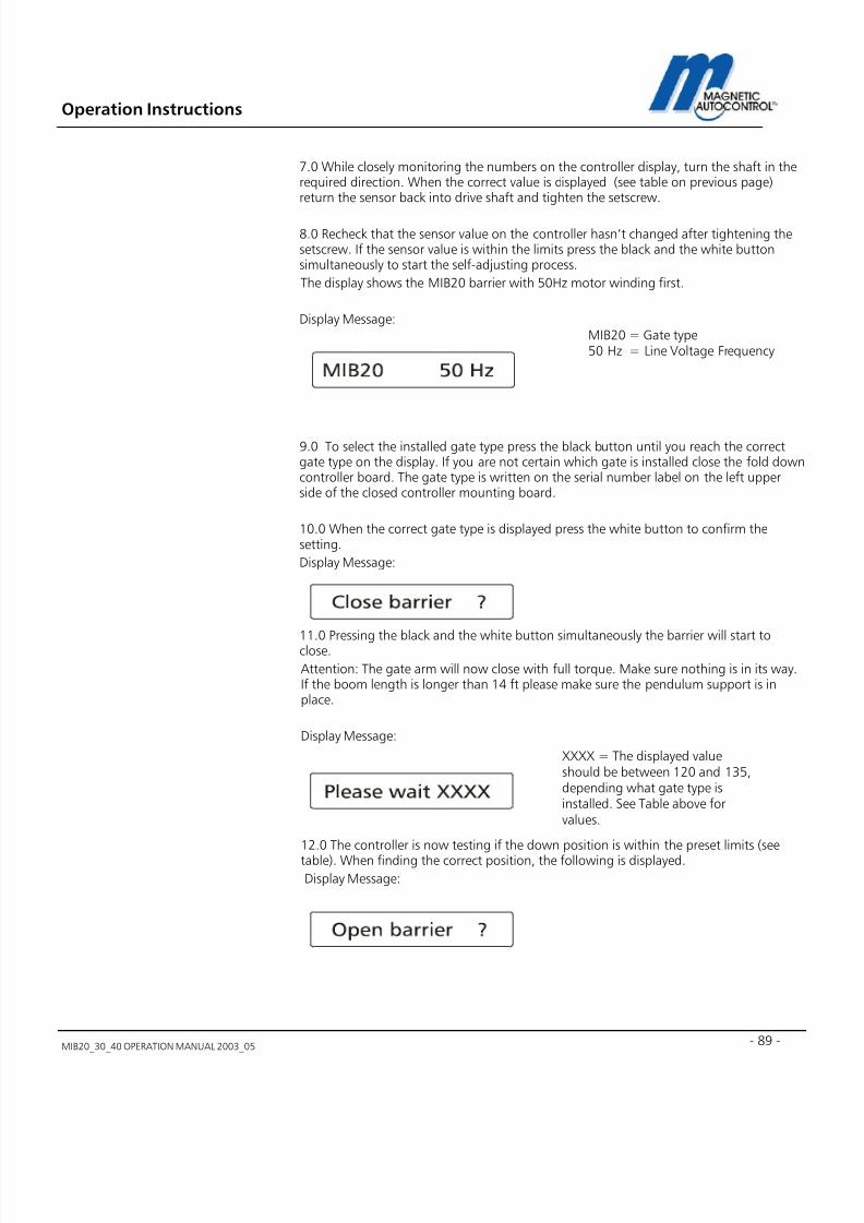
7/22/2019 Mib20!30!40 Operation Manual 2003_05
http://slidepdf.com/reader/full/mib203040-operation-manual-200305 89/106
Operation Instructions
MIB20_30_40 OPERATION MANUAL 2003_05 - 89 -
7.0 While closely monitoring the numbers on the controller display, turn the shaft in therequired direction. When the correct value is displayed (see table on previous page)return the sensor back into drive shaft and tighten the setscrew.
8.0 Recheck that the sensor value on the controller hasn’t changed after tightening thesetscrew. If the sensor value is within the limits press the black and the white buttonsimultaneously to start the self-adjusting process.
The display shows the MIB20 barrier with 50Hz motor winding first.
Display Message:
9.0 To select the installed gate type press the black button until you reach the correctgate type on the display. If you are not certain which gate is installed close the fold downcontroller board. The gate type is written on the serial number label on the left upperside of the closed controller mounting board.
10.0 When the correct gate type is displayed press the white button to confirm thesetting.
Display Message:
11.0 Pressing the black and the white button simultaneously the barrier will start toclose.
Attention: The gate arm will now close with full torque. Make sure nothing is in its way.If the boom length is longer than 14 ft please make sure the pendulum support is inplace.
Display Message:
12.0 The controller is now testing if the down position is within the preset limits (seetable). When finding the correct position, the following is displayed.
Display Message:
MIB20 = Gate type50 Hz = Line Voltage Frequency
XXXX = The displayed valueshould be between 120 and 135,depending what gate type isinstalled. See Table above forvalues.

7/22/2019 Mib20!30!40 Operation Manual 2003_05
http://slidepdf.com/reader/full/mib203040-operation-manual-200305 90/106
Operation Instructions
MIB20_30_40 OPERATION MANUAL 2003_0590
13.0 When pressing the black and the white button simultaneously the barrier will startto open.
Attention: The gate arm will now open with full torque. Make sure nothing is in its way.If the boom length is longer than 14 ft please make sure the pendulum support is inplace
Display Message:
14.0 The controller is now testing if the up position is within the preset limits (see table).When finding the correct position the following is displayed.
Display Message:
15.0 The position sensor is now adjusted. Based on this adjustment the controller mustnow find the optimum brake points for the gate type and the boom length. To do sopress the black and the white button simultaneously.
Display Message:
16.0 When pressing the black and the white button simultaneously the barrier will startthe brake adjustment procedure. During this adjustment the gate will open and closeuntil it finds the optimal brake points. This procedure may take up to 5 minutesdepending on gate type and boom length.
Attention: The gate arm will now cycle up and down. Make sure nothing is in its way. Ifthe boom length is longer than 14 ft please make sure the pendulum support is in place.
17.0 After the gate arm finds the optimum brake points following message is displayed.
Display Message:
XXXX = The displayed value shouldbe between 555 and 580,depending what gate type isinstalled. See Table above forvalues.

7/22/2019 Mib20!30!40 Operation Manual 2003_05
http://slidepdf.com/reader/full/mib203040-operation-manual-200305 91/106
Operation Instructions
MIB20_30_40 OPERATION MANUAL 2003_05 - 91 -
18.0 The controller has now found the optimum brake points for this barrier. To returnto the normal operation turn the rotary switch to position 1 and return it to 0 for normaloperating mode.
22.3 Loop Detector error
The MLC controller is equipped with a loop detector diagnostic feature. If there is a looperror it will be displayed on the controller display.
Following are the detector status display:
A rectangular box means that this loop detector is activated and theloop is connected and read properly.
A rectangular box with a cross means that this loop detector is
activated and a vehicle is present on the loop.
An exclamation mark means that the loop is not activated.

7/22/2019 Mib20!30!40 Operation Manual 2003_05
http://slidepdf.com/reader/full/mib203040-operation-manual-200305 92/106
Operation Instructions
MIB20_30_40 OPERATION MANUAL 2003_0592
Note:
If any of the above error messages appear please make sure that
a. The loop is connected at all
b. The Loop is connected to the proper terminals
c. The Loop has the correct turns and is laid out properly
d. The loop has the correct insulation resistance to earth.
e. That you disabled the loop detectors that are not used.
Please see chapter 16.0 for more details. If you require more detailed informationregarding loop installation and Magnetic Automation’s loop detectors please ask for thenewest INDUCTIVE LOOP DETECTOR MANUAL.
22.4 Gate does not close
There can be different reasons for why the barrier isn’t closing. Following are a fewexamples:
1. Barrier does not go all the way down:
Reason:
A: Make sure that the barrier arm is attached to the gate. The MIB barrier arms arebalanced with springs, without the weight of the arm the motor is not able to close thebarrier.
B: The spring tension is too strong. Ex-Factory the gate is adjusted for the ordered boom
length. If for any reason the arm is shorter then adjusted ex factory the springs need tobe readjusted to balance the new weight of the shorter boom. See chapter 22.6 formore details.
2. Barrier does not react to any closing inputs
Reason:
A: Make sure that input IN5 is made. IN5 is the safety input for external safety devicesother then induction loops connected on Loop A. If Loop A is activated, input IN5 mustbe made (jumper wire terminal 32-33 delivered ex-factory). If an external safety device is
? A question mark means that there is a loop failure or the loop is notconnected.
? A line at the Loop A display and a question mark at loop B means thatloop A is detected but Loop B has a failure or is not connected.
? A line at the Loop B display and a question mark at loop A means thatloop B is detected but Loop A has a failure or is not connected.

7/22/2019 Mib20!30!40 Operation Manual 2003_05
http://slidepdf.com/reader/full/mib203040-operation-manual-200305 93/106
Operation Instructions
MIB20_30_40 OPERATION MANUAL 2003_05 - 93 -
used (for example: Photo Beam) the normally closed contact of this device must beconnected to this terminal. If Input IN5 is not made the gate will not close.
B: Make sure that safety device, externally connected on IN5 (if used) or the internal safety
loop A is not triggered. The barrier won’t close if the safety device is activated.
C: If the gate should close by passing through the safety device please check if the safetydevice is actually being triggered when a vehicle drives through the safety zone. If Loop Ais used for safety/closing check if a cross appears in the square on the Loop A statusdisplay when the vehicle is on the loop. If an external safety/closing device is used makesure the status display of IN5 displays “0” when the vehicle is on the safety zone andreturns to “I” when the vehicle has left. The gate should then close.
D: If using the safety/closing loop/device to close the gate, make sure the Program modeis set to 5,6,7 or 8 (see chapter 5.0 for more details).
C: If you are using inputs to close the barrier make sure you connected it to the correctterminals in respect to the program modes (see chapter 5.0 for more details).
Note:
In any case; if the barrier does not open or close try the provided gateUP/NORMAL/DOWN switch first to determine if the problem comes from the gate or theperipheral equipment.
22.5 Gate does not open There can be several reasons for why the barrier isn’t opening. Following are a fewexamples:
A: The barrier arm is too heavy. The spring tension is too weak. Ex-Factory the gate isadjusted for the ordered boom length. If for any reason the arm is longer or additionalweight was added to it (for example: Stop signs) the springs have to be readjusted tobalance the boom arm. The motor is not strong enough to lift the arm if the springs arenot balanced with the arm. See chapter 22.6 for more details.
B: Make sure the barrier open contact is connected to the correct terminal. See chapter5.0 for details.
C: Make sure that IN3 is not made. This contact has higher priority then IN1. If using IN1
to open the gate IN3 must be off.
Note:
In any case, if the barrier does not open or close try the provided gateUP/NORMAL/DOWN switch first to determine if the problem comes from the gate or theperipheral equipment.

7/22/2019 Mib20!30!40 Operation Manual 2003_05
http://slidepdf.com/reader/full/mib203040-operation-manual-200305 94/106
Operation Instructions
MIB20_30_40 OPERATION MANUAL 2003_0594
22.6 How to change from right-handed gate to left- handed?
On which side of the housing the boom is positioned and in what relation to the roadthe housing is positioned determines if the gate is right or left handed. Please seedrawing below for further details.
Ex-factory we ship the barrier as ordered, either right or left-handed. If during installationthe barrier has to be changed from right to left handed or vise versa please follow thesteps below:
1. Move the barrier to the up position.
2. Turn the electrical power off.
3. Remove the gate arm from the flange.
4. Loosen up or remove the springs (before loosing up the springs please make sureyou remember how tight they were when putting them back on).
5. Loosen (do not completely remove) the two Allen bolts that clamp the shaft lever tothe shaft.
6. Remove the retainer ring that’s holding the shaft in place opposite from the flange.
7. Take off the distance bushings.

7/22/2019 Mib20!30!40 Operation Manual 2003_05
http://slidepdf.com/reader/full/mib203040-operation-manual-200305 95/106
Operation Instructions
MIB20_30_40 OPERATION MANUAL 2003_05 - 95 -
8. You can now pull the shaft out of the drive unit frame. Sometimes it is necessary touse a screwdriver or a similar tool to wedge the shaft lever when pulling the shaftout.
9. Slide the shaft into the opposite side all the way through.10. Replace the distance bushings and the retainer ring.
11. Level the boom flange parallel to the gate housing and retighten the two Allen headbolts.
12. Replace or re-tension the springs to the position in which they originally were.
13. Replace the barrier arm.
14. Turn the power back on.
15. Close the barrier
16. Check the horizontal position of the gate arm to the driveway.
17. If the gate arm is not parallel to the driveway open up the two Allen head bolts thatsecure the shaft lever to the shaft and adjust the arm position.
18. When the arm is parallel to the driveway re-tighten the two Allen head bolts.
Spr ings
Spring
ad justment
screwsShaft
Shaft
Lever
A llen
headscrews
Drawing shows
a r ight handed
barrier.

7/22/2019 Mib20!30!40 Operation Manual 2003_05
http://slidepdf.com/reader/full/mib203040-operation-manual-200305 96/106
Operation Instructions
MIB20_30_40 OPERATION MANUAL 2003_0596
23.0 Technical Data
23.1 MAGSTOP Barriers
MIB20 MIB30 MIB40
Max. Boom length 8FT octagonal/10ftround
12FT octagonal 20 FT octagonal
Opening/closing time 0, 9 sec 1,4 sec 4,0 sec
Power consumption 240 W 120 W 120 W
Housing Zinc-plated sheet steelcolor powder coated
Zinc-plated sheetsteel color powdercoated
Zinc-plated sheetsteel color powdercoated
Housing dimensions
(W x D x H)
14” x 14”x 42” 14” x 14”x 42” 14” x 14”x 42”
Foundation base frame Stainless steel Stainless steel Stainless steel
Weight (without arm) 145 lbs. 145 lbs. 145 lbs.
Operating temp.Range (Ambient)
-22°F TO +140°F -22°F TO +140°F -22°F TO +140°F
Drive Unit Torque motor Torque motor Torque motor
23.2 Controller
Unit MLC10 MLC11*
Voltage (+/- 10%) Volt 100-240 100-240
Frequency Hertz 50 - 60 50 - 60
Max. power
consumption
Watt 20 20
Fuse F4AH F4AH
Control Voltage 24 V DC / max. 300mA
24 V DC / max. 300mA”
No. of inputs 5 5
No of zero-potential
changeover relaysmax.250V AC/3A 2 2 2
No. of open collectoroutputs
max.50mA/24V DC 2 2

7/22/2019 Mib20!30!40 Operation Manual 2003_05
http://slidepdf.com/reader/full/mib203040-operation-manual-200305 97/106
Operation Instructions
MIB20_30_40 OPERATION MANUAL 2003_05 - 97 -
Unit MLC10 MLC11*
Display Characters 16 16
Choice of languages D-GB-F-E D-GB-F-ENo. of loop detectors 2 2
Induction range µH 70 - 500 70 - 500
No of sensitivitysettings
10 10
Sensitivity range % 0.01-2 0.01-2
Protection Class IP 20 20
Weight Lbs 2 2
Dimensions Inch (L x W x H) 7.87”x2.95”x4.64” 7.87”x2.95”x4.64”
*The MIB 20 barrier shall only be used in conjunction with the MLC 11 (external heat sink).
The MLC11 controller requires that the heat sink screw be installed through the fold downsteel mounting plate.

7/22/2019 Mib20!30!40 Operation Manual 2003_05
http://slidepdf.com/reader/full/mib203040-operation-manual-200305 98/106
Operation Instructions
MIB20_30_40 OPERATION MANUAL 2003_0598
24. Maintenance
The MIB20/30/40 series barrier gates are designed for a long lifetime with only aminimum of maintenance required.To guarantee the greatest available equipment uptime and maximize the lifetime of theMIB20/30/40 series barriers please follow the prescribed maintenance schedules.
Use the Maintenance Service Record, located on page 98, to keep track of yourmaintenance and upkeep activities on the MIB series barrier models.
24.1 Changing the Rubber End Stop
The MIB* series barrier gates are equipped with two (2) rubber end stops to absorb theshock generated by the moving gate hitting the end positions.Those rubber end stops need to be replaced once per year or after one million cycleswhatever comes first.
24.2 Checking the Exterior of Cabinet
Inspect the housing for vehicular damage every six months.
24.3 Check the barrier arm and the attachment kit
Inspect the barrier arm for physical damage and check if the barrier arm attachment kit isused properly and all parts are in place and tight. Perform this inspection every sixmonths.
24.4 Checking the Loop Detectors and Loop WiresCheck the frequencies of the loops every six months. The loop wires should be replacedapproximately every four years or as needed. Check the loop sealant every year for cracksor peeling. Replace if needed.
24.5 Check safety signage
Inspect for proper attachment of all safety related signage such as Gate Cabinet andbarrier arm safety sticker.

7/22/2019 Mib20!30!40 Operation Manual 2003_05
http://slidepdf.com/reader/full/mib203040-operation-manual-200305 99/106
Operation Instructions
MIB20_30_40 OPERATION MANUAL 2003_05 - 99 -
This Page was intentionally left blank.

7/22/2019 Mib20!30!40 Operation Manual 2003_05
http://slidepdf.com/reader/full/mib203040-operation-manual-200305 100/106
Operation Instructions
MIB20_30_40 OPERATION MANUAL 2003_05100
24.5 Maintenance Service Record
Maintenance Schedule and Service Record
Gate Model
Gate Serial Number
Date Of Installation
Minimum Date Date Date Date Date
Replace Rubber End Stop Every year
Inspect Cabinet Every 6 months
Inspect barrier arm Every 6 months
Check Loop Frequencies Every 6 months
Check Loop Sealant Every year
Check/replace Loop wires Every 4 years
Replace Gate safety stickerEvery 4 years

7/22/2019 Mib20!30!40 Operation Manual 2003_05
http://slidepdf.com/reader/full/mib203040-operation-manual-200305 101/106
Operation Instructions
MIB20_30_40 OPERATION MANUAL 2003_05 - 101 -
25. Spare parts
MIB20 / 30 / 40
1018,5001Motor lever
2047,5000Upper spring bracket
1071,5004Lower spring bracket
3004,0001Rubber
End stop
1031,0321Potentiometer
1014,0029Flange-shaft
Housing base2061,0070 (Orange)2061.5027 (White)2061.5042 (Yellow)
2061.5041 (Red)
Housing door2043,0152 (Orange)2043.5082 (White)2043.5097 (Yellow)
2061.5096 (Red)
Housing Lid2029,0023 (Orange)2029.5031 (White)2043.5040 (Yellow)
2061.5039 (Red)

7/22/2019 Mib20!30!40 Operation Manual 2003_05
http://slidepdf.com/reader/full/mib203040-operation-manual-200305 102/106
Operation Instructions
MIB20_30_40 OPERATION MANUAL 2003_05102
3468,0028#18 Lock for hood and door
3004,0005Hood bumper
3224,0020Door Gasket
3466,0019#18 Key
3514,5000Wave-ring
For hood plug
3502,5001Distance RingFor hood plug
Yellow mark2036,0021
2036,0021Spring, strongFor MIB40 only
2036,0022Spring weak
For MIB20/30

7/22/2019 Mib20!30!40 Operation Manual 2003_05
http://slidepdf.com/reader/full/mib203040-operation-manual-200305 103/106
Operation Instructions
MIB20_30_40 OPERATION MANUAL 2003_05 - 103 -
1006,0029Capacitor 16µf
1006,0030Capacitor 20µf
1031,0180Boom attachment kit
1031,0253Boom Flange
1031,5055Flange-set complete
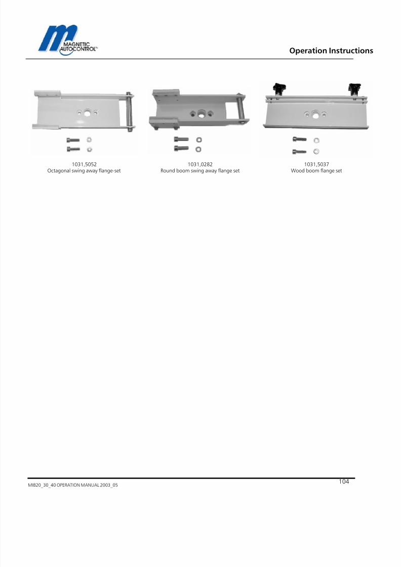
7/22/2019 Mib20!30!40 Operation Manual 2003_05
http://slidepdf.com/reader/full/mib203040-operation-manual-200305 104/106
Operation Instructions
MIB20_30_40 OPERATION MANUAL 2003_05104
1031,5052Octagonal swing away flange-set
1031,0282Round boom swing away flange set
1031,5037Wood boom flange set

7/22/2019 Mib20!30!40 Operation Manual 2003_05
http://slidepdf.com/reader/full/mib203040-operation-manual-200305 105/106
Operation Instructions
MIB20_30_40 OPERATION MANUAL 2003_05 - 105 -
Notes:

7/22/2019 Mib20!30!40 Operation Manual 2003_05
http://slidepdf.com/reader/full/mib203040-operation-manual-200305 106/106
Operation Instructions