mi 3280 instruction manual - rapid-tech.com.au · metrel d.d. ljubljanska cesta 77 1354 horjul...
TRANSCRIPT

Digital Transformer Analyser MI 3280
Instruction manual Version 1.1.1; Code No. 20 752 598

2
Distributor: Manufacturer: METREL d.d. Ljubljanska cesta 77 1354 Horjul Slovenia web site: http://www.metrel.si e-mail: [email protected]
Mark on your equipment certifies that it meets European Union requirements for EMC, LVD, ROHS regulations.
© 2016 METREL
The trade names Metrel, Smartec, Eurotest, Auto Sequence® are trademarks registered or pending in Europe and other countries. No part of this publication may be reproduced or utilized in any form or by any means without permission in writing from METREL.

MI 3280 DT Analyser Table of contents
3
Table of contents
1 General Description ........................................................................................... 6 1.1 Features ...................................................................................................... 6
2 Safety and operational considerations ............................................................ 7 2.1 Warnings and notes ..................................................................................... 7 2.2 Battery and charging of Li-ion battery pack .................................................. 9
2.2.1 Precharge ........................................................................................... 10 2.2.2 Li – ion battery pack guidelines........................................................... 12
2.3 Standards applied ...................................................................................... 13
3 Terms and definitions ...................................................................................... 14
4 Instrument description .................................................................................... 15 4.1 Instrument casing ...................................................................................... 15 4.2 Operator’s panel ........................................................................................ 15
5 Accessories ..................................................................................................... 16 5.1 Standard set .............................................................................................. 16 5.2 Optional accessories ................................................................................. 16
6 Instrument operation ....................................................................................... 17 6.1 General meaning of keys ........................................................................... 17 6.2 General meaning of touch gestures ........................................................... 17 6.3 Virtual keyboard......................................................................................... 18 6.4 Display and sound ..................................................................................... 19
6.4.1 Battery and time indication ................................................................. 19 6.4.2 Messages ........................................................................................... 19 6.4.3 Sound indication ................................................................................. 22 6.4.4 Help screens ...................................................................................... 22
7 Main menu ........................................................................................................ 23 7.1 Instruments main menu ............................................................................. 23
8 General Settings .............................................................................................. 24 8.1 Language .................................................................................................. 25 8.2 Power Save ............................................................................................... 25 8.3 Date and time ............................................................................................ 26 8.4 Instrument profiles ..................................................................................... 26 8.5 Settings ..................................................................................................... 27 8.6 Initial Settings ............................................................................................ 28 8.7 About ......................................................................................................... 28 8.8 Auto Sequence® groups............................................................................ 29
8.8.1 Auto Sequence groups menu ............................................................. 29 8.8.2 Operations in Auto Sequence groups menu: ...................................... 29 8.8.3 Selecting a list of Auto Sequences ..................................................... 30 8.8.4 Deleting a list of Auto Sequences ....................................................... 30
8.9 Workspace manager ................................................................................. 31 8.9.1 Workspaces and Exports .................................................................... 31 8.9.2 Workspace Manager main menu ........................................................ 31 8.9.3 Operations with Workspaces .............................................................. 32 8.9.4 Operations with Exports...................................................................... 32 8.9.5 Adding a new Workspace ................................................................... 33

MI 3280 DT Analyser Table of contents
4
8.9.6 Opening a Workspace ........................................................................ 34 8.9.7 Deleting a Workspace / Export ........................................................... 34 8.9.8 Importing a Workspace ....................................................................... 35 8.9.9 Exporting a Workspace....................................................................... 35
9 Memory Organizer ........................................................................................... 37 9.1 Memory Organizer menu ........................................................................... 37
9.1.1 Measurement statuses ....................................................................... 37 9.1.2 Structure items ................................................................................... 38 9.1.3 Measurement status indication under the Structure item .................... 38 9.1.4 Operations in Tree menu .................................................................... 39
10 Single tests ...................................................................................................... 51 10.1 Selection modes ........................................................................................ 51
10.1.1 Single test screens ............................................................................. 52 10.1.2 Setting parameters and limits of single tests ....................................... 53 10.1.3 Setting parameters through scrollable list ........................................... 54 10.1.4 Setting parameters through keyboard ................................................. 54 10.1.5 Single test result screen ..................................................................... 55 10.1.6 Recall single test result screen ........................................................... 56 10.1.7 Single test (Visual Test) screens ........................................................ 57 10.1.8 Single test (Visual Test) start screen .................................................. 57 10.1.9 Single test (Visual Test) screen during test ......................................... 58 10.1.10 Single test (Visual Test) result screen................................................. 59 10.1.11 Single test (Visual Test) memory screen ............................................ 60
11 Tests and Measurements ................................................................................ 61 11.1 Visual tests ................................................................................................ 61 11.2 Turn ratio [r, rA,rB,rC]................................................................................... 63
11.2.1 Single-phase transformers .................................................................. 63 11.2.2 Three-phase transformers .................................................................. 69
11.3 Winding resistance [R, RA,RB,RC] .............................................................. 73 11.3.1 Single-phase transformers .................................................................. 73 11.3.2 Testing, connection and results .......................................................... 74 11.3.3 Three-phase transformers .................................................................. 76
12 Auto Sequence® .............................................................................................. 79 12.1 Selection of Auto Sequence® .................................................................... 79 12.2 Organization of Auto Sequence® .............................................................. 80
12.2.1 Auto Sequence view menu ................................................................. 80 12.2.2 Step by step executions of Auto Sequence ........................................ 82 12.2.3 Auto Sequence result screen .............................................................. 83 12.2.4 Auto Sequence memory screen .......................................................... 85
13 Communication ................................................................................................ 86
14 Maintenance ..................................................................................................... 87 14.1 Cleaning .................................................................................................... 87 14.2 Periodic calibration .................................................................................... 87 14.3 Service ...................................................................................................... 87 14.4 Upgrading the instrument .......................................................................... 87
15 Technical specifications ................................................................................. 88 15.1 Turn ratio measurement [r, rA, rB, rC,] ......................................................... 88
MI 3280 DT Analyser Table of contents
5
15.2 Winding resistance [R, RA, RB, RC] .......................................................... 89 15.3 General data .............................................................................................. 90
Appendix A – Structure objects........................................................................ 91
Appendix B – Profile Notes ............................................................................... 92
Appendix C – Impedance of Power sources .................................................... 93
Appendix D – Vector groups ............................................................................. 94 D.1 Vector groups of three-phase transformer ................................................. 94
D.1.1 IEC / ANSI vector groups .................................................................... 94
Appendix E – Detailed wiring diagram of specific measurements .............. 102
Appendix F – Testing the instrument precision ............................................ 105
Appendix G – Programming of Auto Sequence® on Metrel ES Manager .... 106
MI 3280 DT Analyser General Description
6
1 General Description
1.1 Features Digital Transformer (DT) Analyser (MI 3280) is a Multi-function, portable battery (Li-ion) powered test instrument with excellent IP protection: IP65 (case closed), IP54 (case open), intended for diagnosing of: turn ratio, phase deviation and excitation current of single and three phase transformer and winding resistance of single and three phase transformer. Available functions and features offered by the Digital Transformer Analyser:
Turn ratio measurement of single and three phase transformer; Phase deviation between high voltage and low voltage winding Excitation current when measuring turn ratio
Winding resistance measurement of single and three phase transformer; Auto Sequences®; Visual Tests; Memory Organizer.
A 4.3'' (10.9 cm) colour LCD display with touch screen offers easy-to-read results and all
associated parameters. The operation is straightforward and clear to enable the user to operate the instrument without the need for special training (except reading and understanding this Instruction Manual). Test results can be stored on the instrument. PC software that is supplied as a part of standard set, enables transfer of measured results to PC where can be analysed or printed.

MI 3280 DT Analyser Safety and operational considerations
7
2 Safety and operational considerations
2.1 Warnings and notes In order to maintain the highest level of operator safety while carrying out various tests and measurements Metrel recommends keeping your MI 3280 DT Analyser instruments in good condition and undamaged. When using the instrument, consider the following general warnings:
The symbol on the instrument means »Read the Instruction manual with special care for safe operation«. The symbol requires an action!
If the test equipment is used in a manner not specified in this user manual, the protection provided by the equipment could be impaired!
Read this Instruction manual carefully, otherwise the use of the instrument may be dangerous for the operator, the instrument or for the equipment under test!
Do not use the instrument or any of the accessories if any damage is noticed!
Consider all generally known precautions in order to avoid risk of electric shock while dealing with hazardous voltages!
Do not connect the instrument to a mains voltage different from the one defined on the label adjacent to the mains connector, otherwise the instrument may be damaged and safety impaired.
Service intervention or adjustment is only allowed to be carried out by competent authorized personnel!
Use only standard or optional test accessories supplied by your distributor!
Do not use the equipment in a wet environment, around explosive gas, vapour.
All normal safety precautions must be taken in order to avoid risk of electric shock while working on electrical installations!
Markings on the instrument:
Read the Instruction manual with special care to safety operation«. The symbol requires an action!
Mark on your equipment certifies that it meets European Union requirements for EMC, LVD, and ROHS regulations.
This equipment should be recycled as electronic waste.
Instrument has double insulation.

MI 3280 DT Analyser Safety and operational considerations
8
Warnings related to measurement functions: Working with the instrument
Use only standard or optional test accessories supplied by your distributor!
Make sure that the tested object is disconnected (from mains and from the load) before you connect any MI 3280 clips to the test object! One side of earth connection can remain connected.
Always connect accessories to the instrument and to the test object before starting measurement. Do not touch test leads or crocodile clips during measurement.
Do not touch any conductive parts of equipment under test during the test. There is a risk of electric shock!
Do not connect test terminals to an external voltage higher than 50 V DC or AC (CAT IV environment) to prevent any damage to the test instrument!
Handling with inductive loads
Note that large inductances (transformers) can store large amount of energy, which can lead to hazardous electric shock and equipment damage if disconnected during measurement.
Never touch the measured object during testing until it is totally discharged.
Warnings related to Batteries:
Use only batteries provided by the manufacturer. Never dispose of the batteries in a fire as it may cause them to explode or generate
a toxic gas. Do not attempt to disassemble, crush or puncture the batteries in any way. Do not short circuit or reverse polarity the external contacts on a battery. Keep the battery away from children. Avoid exposing the battery to excessive shock/impacts or vibration. Do not use a damaged battery. The Li – ion battery contains safety and protection circuit, which if damaged, may
cause the battery to generate heat, rupture or ignite. Do not leave a battery on prolonged charge when not in use. If a battery has leaking fluids, do not touch any fluids. In case of eye contact with fluid, do not rub eyes. Immediately flush eyes
thoroughly with water for at least 15 minutes, lifting upper and lower lids, until no evidence of the fluid remains. Seek medical attention.

MI 3280 DT Analyser Safety and operational considerations
9
2.2 Battery and charging of Li-ion battery pack The instrument is designed to be powered by rechargeable Li-ion battery pack or with mains supply. The LCD contains an indication of battery condition and the power source (upper left section of LCD). In case the battery is too weak the instrument indicates this as shown in Figure 2.1.
Symbol:
Indication of low battery.
Figure 2.1: Battery test
The battery is charged whenever the power supply is connected to the instrument. The power supply socket is shown in Figure 2.2. Internal circuit controls (CC, CV) charging and assures maximum battery lifetime. Nominal operating time is declared for battery with nominal capacity of 4.4 Ah.
Figure 2.2: Power supply socket (C7)
The instrument automatically recognizes the connected power supply and begins charging.
Symbol:
Indication of battery charging
Figure 2.3: Charging indication (animation)
Battery and charging characteristic Typical
Battery type VB 18650
Charging mode CC / CV
Nominal voltage 14,8 V
Rated capacity 4,4 Ah
Max charging voltage 16,7 V
Max charging current 1,2 A
Max discharge current 2,5 A
Typical charging time 4 hours

MI 3280 DT Analyser Safety and operational considerations
10
Typical charging profile, which is also used in this instrument, is shown in Figure 2.4.
ICH/8
Fastcharge Safety TimePrecharge
Time
Current Regulation Voltage Regulation
ICH
VREG
VLOWV
Charge Current
Charge Voltage
Figure 2.4: Typical charging profile
where: VREG .................................... Battery charging voltage VLOWV .................................. Precharge threshold voltage ICH ....................................... Battery charging current ICH/8 ..................................... 1/8 of the charging current
2.2.1 Precharge
On power up, if the battery voltage is below the VLOWV threshold, the charger applies 1/8 of the charging current to the battery. The precharge feature is intended to revive deeply discharged battery. If the VLOWV threshold is not reached within 30 minutes of initiating precharge, the charger turns off and a FAULT is indicated.
Figure 2.5: Battery fault indication (charging suspended, timer fault, battery absent)
Figure 2.6: Battery full indication (charging completed)
Note: As a safety backup, the charger also provides an internal 5-hour charge timer for fast
charge.

MI 3280 DT Analyser Safety and operational considerations
11
Typical charging time is 4 hours in the temperature range of 5°C to 60°C.
Ich/8
Ich
TL
TF
TC
OO
L
TW
AR
M
TH
TF
Charge
Suspended
Charge
Suspended
Temperature
Cu
rre
nt
Charge
Figure 2.7: Typical charging current vs temperature profile
where: TLTF ..................................... Cold temperature threshold (typ. -15°C) TCOOL ................................... Cool temperature threshold (typ. 0°C) TWARM .................................. Warm temperature threshold (typ. +60°C) THTF ..................................... Hot temperature threshold (typ. +75°C)
The charger continuously monitors battery temperature. To initiate a charge cycle, the battery temperature must be within the TLTF to THTF thresholds. If battery temperature is outside of this range, the controller suspends charge and waits until the battery temperature is within the TLTF to THTF range. If the battery temperature is between the TLTF and TCOOL thresholds or between the TWARM and THTW thresholds, charge is automatically reduced to ICH/8 (1/8 of the charging current).

MI 3280 DT Analyser Safety and operational considerations
12
2.2.2 Li – ion battery pack guidelines
Li – ion rechargeable battery pack requires routine maintenance and care in their use and handling. Read and follow the guidelines in this Instruction manual to safely use Li – ion battery pack and achieve the maximum battery life cycles. Do not leave batteries unused for extended periods of time – more than 6 months (self – discharge). When a battery has been unused for 6 months, check the charge status see chapter 6.4.1
Battery and time indication. Rechargeable Li – ion battery pack has a limited life and will gradually lose their capacity to hold a charge. As the battery loses capacity, the length of time it will power the product decreases. Storage:
Charge or discharge the instruments battery pack to approximately 50% of capacity before storage.
Charge the instrument battery pack to approximately 50% of capacity at least once every 6 months.
Transportation:
Always check all applicable local, national, and international regulations before transporting a Li – ion battery pack.
Handling Warnings:
Do not disassemble, crush, or puncture a battery in any way. Do not short circuit or reverse polarity the external contacts on a battery. Do not dispose of a battery in fire or water. Keep the battery away from children. Avoid exposing the battery to excessive shock/impacts or vibration. Do not use a damaged battery. The Li – ion battery contains safety and protection circuit, which if damaged, may
cause the battery to generate heat, rupture or ignite. Do not leave a battery on prolonged charge when not in use. If a battery has leaking fluids, do not touch any fluids. In case of eye contact with fluid, do not rub eyes. Immediately flush eyes
thoroughly with water for at least 15 minutes, lifting upper and lower lids, until no evidence of the fluid remains. Seek medical attention.
MI 3280 DT Analyser Safety and operational considerations
13
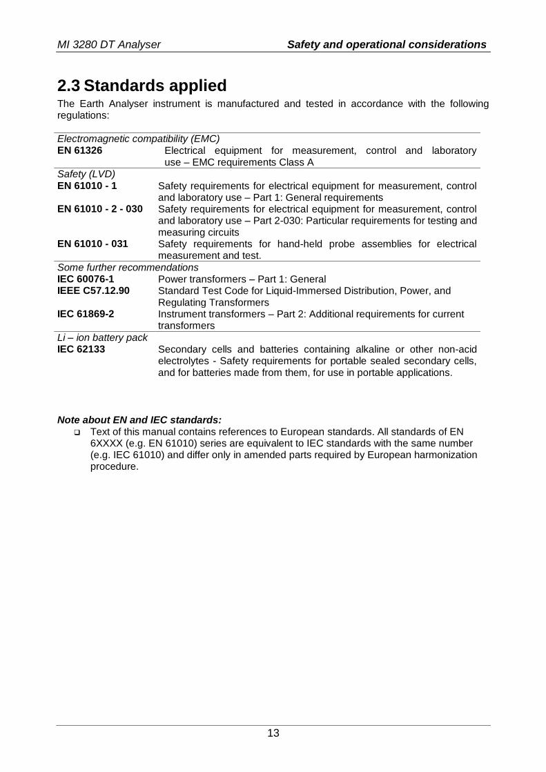
2.3 Standards applied The Earth Analyser instrument is manufactured and tested in accordance with the following regulations:
Electromagnetic compatibility (EMC) EN 61326 Electrical equipment for measurement, control and laboratory
use – EMC requirements Class A Safety (LVD) EN 61010 - 1 Safety requirements for electrical equipment for measurement, control
and laboratory use – Part 1: General requirements EN 61010 - 2 - 030 Safety requirements for electrical equipment for measurement, control
and laboratory use – Part 2-030: Particular requirements for testing and measuring circuits
EN 61010 - 031 Safety requirements for hand-held probe assemblies for electrical measurement and test.
Some further recommendations IEC 60076-1 Power transformers – Part 1: General IEEE C57.12.90 Standard Test Code for Liquid-Immersed Distribution, Power, and
Regulating Transformers IEC 61869-2 Instrument transformers – Part 2: Additional requirements for current
transformers
Li – ion battery pack IEC 62133 Secondary cells and batteries containing alkaline or other non-acid
electrolytes - Safety requirements for portable sealed secondary cells, and for batteries made from them, for use in portable applications.
Note about EN and IEC standards:
Text of this manual contains references to European standards. All standards of EN 6XXXX (e.g. EN 61010) series are equivalent to IEC standards with the same number (e.g. IEC 61010) and differ only in amended parts required by European harmonization procedure.

MI 3280 DT Analyser Terms and definitions
14
3 Terms and definitions For the purposes of this document and instrument MI 3280 DT Analyser, the following definitions apply.
Index: Unit: Description:
RH [Ω] Winding resistance of high voltage winding (H) of single phase transformer
RX [Ω] Winding resistance of low voltage winding (X) of single phase transformer
RHA [Ω] Phase A winding resistance of high voltage side (HA) of three phase transformer
RHB [Ω] Phase B winding resistance of high voltage side (HB) of three phase transformer
RHC [Ω] Phase C winding resistance of high voltage side (HC) of three phase transformer
RXA [Ω] Phase A winding resistance of low voltage side (XA) of three phase transformer
RXB [Ω] Phase B winding resistance of low voltage side (XB) of three phase transformer
RXC [Ω] Phase C winding resistance of low voltage side (XC) of three phase transformer
r [ ] Turn ratio of single phase transformer
rA [ ] Turn ratio of phase A of three phase transformer
rB [ ] Turn ratio of phase B of three phase transformer
rC [ ] Turn ratio of phase C of three phase transformer
r [%] Turn ratio deviation of single phase transformer
rA [%] Turn ratio deviation of phase A of three phase transformer
rB [%] Turn ratio deviation of phase B of three phase transformer
rC [%] Turn ratio deviation of phase C of three phase transformer
i [A] Excitation current when measuring turn ration of single phase transformer
iA [A] Excitation current when measuring turn ration of phase A of three phase transformer
iB [A] Excitation current when measuring turn ration of phase B of three phase transformer
iC [A] Excitation current when measuring turn ration of phase C of three phase transformer
φ [°] Phase deviation of voltage between high voltage winding (H) voltage and low voltage winding (X) of single phase transformer
φA [°] Phase deviation of phase A voltage between high voltage winding (H) voltage and low voltage winding (X) of three phase transformer
φB [°] Phase deviation of phase B voltage between high voltage winding (H) voltage and low voltage winding (X)
φC [°] Phase deviation of phase C voltage between high voltage winding (H) voltage and low voltage winding (X)
RH [Ω] Winding resistance of high voltage winding (H) of single phase transformer
RX [Ω] Winding resistance of low voltage winding (X) of single phase transformer
RHA [Ω] Phase A winding resistance of high voltage side (HA) of three phase transformer
RHB [Ω] Phase B winding resistance of high voltage side (HB) of three phase transformer
RHC [Ω] Phase C winding resistance of high voltage side (HC) of three phase transformer
RXA [Ω] Phase A winding resistance of low voltage side (XA) of three phase transformer
RXB [Ω] Phase B winding resistance of low voltage side (XB) of three phase transformer
RXC [Ω] Phase C winding resistance of low voltage side (XC) of three phase transformer
fex [Hz] Excitation frequency
Iex [A] Excitation current when measuring winding resistance
Designation of the terminals:
H0 | H1 - terminal for high voltage transformer windings (H) clips, H0 and H1; H2 | H3 - terminal for high voltage transformer windings (H) clips, H2 and H3; X0 | X1 - terminal for low voltage transformer winding (X) clips, X0 and X1; X2 | X3 - terminal for low voltage transformer winding (X) clips, X2 and X3;

MI 3280 DT Analyser Instrument description
15
4 Instrument description
4.1 Instrument casing The instrument is housed in a plastic box that maintains the protection class defined in the general specifications.
4.2 Operator’s panel The operator’s panel is shown in Figure 4.1 below.
Figure 4.1: The operator’s panel
1 Colour TFT display with touch screen
2 H0 | H1 Terminal (high voltage side of a transformer)
3 H2 | H3 Terminal (high voltage side of a transformer)
4 X0 | X1 Terminal (low voltage side of a transformer)
5 X2 | X3 Terminal (low voltage side of a transformer)
6 Keypad (see section 6.1 General meaning of keys)
7 USB Communication port (standard USB connector - type B)
8 Remote / Tap changer (DB-9)
9 Input power supply socket (type C7)
Warnings!
Maximum allowed voltage between any test terminal and ground is 50 V!
Use original test accessories only!

MI 3280 DT Analyser Accessories
16
5 Accessories The accessories consist of standard and optional accessories. Optional accessories can be delivered upon request. See attached list for standard configuration and options or contact your
distributor or see the METREL home page: http://www.metrel.si. MI 3280 DT Analyser is available in multiple sets with a combination of different accessories and measurement functions. The functionality of an existing set can be expanded by ordering additional accessory and license keys.
Measurement functions available Profile Code APAA
Name MI 3280
Icon
Turn ratio:
single - phase transformer •
three - phase transformer •
Winding resistance:
single - phase transformer •
three - phase transformer •
Visual Tests •
5.1 Standard set Code: Application notes:
Instrument DT Analyser MI 3280
1 x H0 | H1 dual red Kelvin clips: (2,5m black/yellow leads)
A 1515
1 x H2 | H3 dual red Kelvin clips: (2,5m white/green leads)
A 1516
1 x X0 | X1 dual grey Kelvin clips: (2,5m black/yellow leads)
A 1517
1 x X2 | X3 dual grey Kelvin clips: (2,5m white/green leads)
A 1518
Other accessories:
Mains cable USB cable Bag for accessories PC SW Metrel ES Manager Instruction manual Calibration certificate
5.2 Optional accessories See the attached sheet for a list of optional accessories and licence keys that are available on request from your distributor.

MI 3280 DT Analyser Instrument operation
17
6 Instrument operation The MI 3280 DT Analyser instrument can be manipulated via a keypad or touch screen.
6.1 General meaning of keys
Cursor keys are used to: select appropriate option; decrease, increase the selected parameter.
Enter key is used to: confirm selected option.
Escape key is used to: return to previous menu without changes; abort measurement.
Second function: switches the instrument power on
or off (hold key for 2 s for confirmation screen);
instrument hard off (hold key for 5 s or more).
The instrument automatically turns off 10 minutes after the last key was pressed.
Tab key is used to:
expand column in control panel.
Run key is used to: start and stop the measurements.
6.2 General meaning of touch gestures
Tap (briefly touch surface with fingertip) is used to: select appropriate option; confirm selected option; start and stop measurements.
Swipe (press, move, lift) up/ down is used to: scroll content in same level; navigate between views in same level.
long
Long press (touch surface with fingertip for at least 1 s) is used to: select additional keys (virtual keyboard); select test or measurement using cross selector.
Tap Escape icon is used to: return to previous menu without changes; abort measurements.

MI 3280 DT Analyser Instrument operation
18
6.3 Virtual keyboard
Figure 6.1: Virtual keyboard
Toggle case between lowercase and uppercase. Active only when alphabetic characters’ keyboard layout selected.
Backspace Clears last character or all characters if selected (If held for 2 s, all characters are selected).
Enter confirms new text.
Activates numeric / symbols layout.
Activates alphabetic characters.
English keyboard layout.
Greek keyboard layout.
Russian keyboard layout.
Returns to the previous menu without changes.

MI 3280 DT Analyser Instrument operation
19
6.4 Display and sound
6.4.1 Battery and time indication
The battery indication indicates the charge condition of battery and connection of external charger.
Battery capacity indication.
Low battery. Recharge the battery cells.
Battery is full.
Battery fault indication.
Charging in progress (if power supply adapter is connected and battery inserted).
Time indication (hh:mm).
6.4.2 Messages
In the message field warnings and messages are displayed.
Conditions on the input terminals allow starting the measurement; consider other displayed warnings and messages.
Conditions on the input terminals do not allow starting the measurement, consider displayed warnings and messages.
Stop the measurement.
Result(s) can be stored.
Opens menu for changing parameters and limits.
Previous screen view.
Next screen view.
Opens help screen.
Views results of measurement.

MI 3280 DT Analyser Instrument operation
20
Pass ticker in Visual test.
Fail ticker in Visual test.
Clear ticker in Visual test.
Checked ticker in Visual test.
Expands control panel / open more options.
Measurement is running, consider displayed warnings.
Low output voltage. In case of measuring transformers with very large turn ratio the low voltage winding (X) voltage may be too low to maintain high precision. This icon indicates that if it is possible to increase excitation voltage (Vex) this
should be done. This icon indicates the result is still valid but with lower precision.
Low excitation current. Measurement was made with very low current. The possible reason is very high impedance (when measuring turn ratio) or measuring clips are disconnected from the transformer.
Timeout. Maximum measuring time was exceeded. Transformer inductance is too large or unexpected error occurred during measurement.
No connection. At least H or X one testing clip is not connected to the
transformer or at least one winding has resistance greater than 5 k.
Overvoltage detected at start-up
In pre-test procedure a voltage is measured on all clips (H and X), that will be used in complete transformer testing.
Possible causes:
Transformer is connected to a power source.
Induced voltage is present on a certain probe pair.
Select OK for acknowledgement, remove all power
sources connected to the transformer and repeat the test.

MI 3280 DT Analyser Instrument operation
21
Voltage over range
During operation voltage is measured on all clips and overvoltage is detected with internal overvoltage protection circuitry.
Possible causes:
At least one high voltage clip (H) is connected to low voltage side (X) of the transformer.
Turn ratio (r) is to low (< 0.8).
Select OK for acknowledgement, check connection and/or decrease excitation voltage (Vex) and repeat the
test.
Current over range
During operation excitation current is measured.
Possible causes:
Impedance on high voltage side (H) of the transformer is too low for selected Vex.
Select OK for acknowledgement, lower the excitation voltage (Vex) and repeat the test.
Current to low (< 1mA)
During winding resistance measurement operation voltage is measured sequentially.
Possible causes:
Phase to phase resistance is too high.
At least one clip indicated in the message is disconnected.
Select OK for acknowledgement, check connection and repeat the test.
Very low voltage detected
During turn ratio measurement voltage is measured on all clips.
Possible causes:
Transformer is not connected properly.
Excitation voltage is too low.
Select OK for acknowledgement, increase the excitation voltage (Vex) if possible and repeat the test.
Limit The user is allowed to set the limit of relative turn ratio difference (Δr). Relative difference between measured turn ratio and calculated turn ratio is compared against the limit. Result is validated only if it is within the given limit. Limit indication is shown in the test parameter window.

MI 3280 DT Analyser Instrument operation
22
Message window:
Measurement result is inside pre-set limits (PASS).
Measurement result is out of pre-set limits (FAIL).
Measurement is aborted. Consider displayed warnings and messages.
Note:
Pass / Fail indication is only displayed if limit is set.
6.4.3 Sound indication
Two beeps sound
PASS! Means that the measuring result data lies inside expected limits.
One long beep sound
FAIL! Means that the measuring result data is out of predefined limits.
6.4.4 Help screens
Opens help screen.
Help menus are available in all functions. The Help menu contains schematic diagrams for illustrating proper connection of the instrument to the test object. After selecting the measurement, you want to perform, tap on question mark in order to view the associated Help menu.
on
Selects next / previous help screen.
Exits help menu.
Figure 6.2: Examples of help screens

MI 3280 DT Analyser Main menu
23
7 Main menu
7.1 Instruments main menu From the Main menu different main operation menus can be selected.
Figure 7.1: Main menu
Options in main menu:
Single Tests Menu with single tests, see chapter 11 Tests and Measurements for more information.
Menu with customized test sequences, see chapter 12 Auto Sequence® for more information.
Memory Organizer Menu for working with and documentation of test data, see chapter 9 Memory Organizer for more information.
General Settings Menu for setup of the instrument, see chapter 8 General Settings for more information.

MI 3280 DT Analyser General Settings
24
8 General Settings In the General settings menu general parameters and settings of the instrument can be viewed or
set.
Figure 8.1: General settings menu
Options in General Settings menu:
Language
Instrument language selection. Refer to chapter 8.1 Language for
more information.
Power Save
Brightness of LCD, enabling/disabling Bluetooth communication. Refer to chapter 8.2 Power Save for more information.
Date /Time
Instruments Date and time. Refer to chapter 8.3 Date and time for more information.
Workspace Manager
Manipulation with project files. Refer to chapter 8.9 Workspace manager for more information.
Auto Sequence® groups
Manipulation with lists of Auto Sequence®. Refer to chapter 8.8 Auto Sequence® groups for more information.
Instrument Profile
Selection of available instrument profiles. Refer to chapter 8.4 Instrument profiles for more information.
Settings
Settings of different system / measuring parameters. Refer to chapter 8.5 Settings for more information.
Initial Settings
Factory settings. Refer to chapter 8.6 Initial Settings for more information.
About
Instrument info. Refer to chapter 8.7 About for more information.

MI 3280 DT Analyser General Settings
25
8.1 Language In this menu the language of the instrument can be set.
Figure 8.2: Language menu
8.2 Power Save In this menu different options for decreasing power consumption can be set.
Figure 8.3: Power save menu
Brightness Setting level of LCD brightness level.
LCD off time Setting LCD off after set time interval. LCD is switched on after pressing any key or touching the LCD.
Bluetooth Always On: Bluetooth module is ready to communicate. Save mode: Bluetooth module is set to sleep mode and is not functioning.

MI 3280 DT Analyser General Settings
26
8.3 Date and time In this menu the date and time of the instrument can be set.
Figure 8.4: Setting date and time
8.4 Instrument profiles In this menu the instrument profile can be selected from the available ones.
Figure 8.5:Instrument profiles menu
The instrument uses different specific system and measuring settings regarding to the scope of work or country it is used. These specific settings are stored in instrument profiles. By default, each instrument has at least one profile activated. Proper licence keys must be obtained to add more profiles to the instruments. If different profiles are available, they can be selected in this menu. For more information, refer to chapter Appendix B – Profile Notes.
Options
Loads the selected profile. The instrument will restart automatically with new profile loaded.
Deletes the selected profile.

MI 3280 DT Analyser General Settings
27
Before deleting the selected profile user is asked for confirmation.
Expands control panel / open more options.
8.5 Settings In this menu different general parameters can be set.
Figure 8.6: Settings menu
Available selection Description
Touch screen [ON, OFF] Enables / disables operation with touch screen.
Keys & touch sound [ON, OFF] Enables / disables sound when using keys and touch screen.

MI 3280 DT Analyser General Settings
28
8.6 Initial Settings In this menu the instrument settings, measurement parameters and limits can be set to initial (factory) values.
Figure 8.7: Initial settings menu
Warning: Following customized settings will be lost when setting the instruments to initial settings:
Measurement limits and parameters. Parameters and settings in General settings menu. Applying the initial settings will re-boot the instrument.
Notes: Following customized settings will stay:
Profile settings. Data in memory.
8.7 About In this menu instrument data (name, version, serial number and date of calibration) can be viewed.
Figure 8.8: Instrument info screen

MI 3280 DT Analyser General Settings
29
8.8 Auto Sequence® groups The Auto Sequence in MI 3280 DT Analyser can be organized in lists of Auto Sequence. In a list a group of similar Auto Sequence is stored. The Auto Sequence groups menu is intended to manage with different lists of Auto Sequences that are stored on the internal microSD card.
8.8.1 Auto Sequence groups menu
In Auto Sequence groups menu lists of Auto Sequences are displayed. Only one list can be opened in the instrument at the same time. The list selected in the Auto Sequence groups menu will be opened in the Auto Sequence main menu.
Figure 8.9: Auto Sequence groups menu
8.8.2 Operations in Auto Sequence groups menu:
Options
Opens the selected list of Auto Sequence. Previously selected list of Auto Sequences will be closed automatically. Refer to chapter 8.8.3 Selecting a list of Auto Sequence for more information.
Deletes the selected list of Auto Sequences. Refer to chapter 8.8.4 Deleting a list of Auto Sequence for more information.
Opens options in control panel / expands column.

MI 3280 DT Analyser General Settings
30
8.8.3 Selecting a list of Auto Sequences
Procedure
A list of Auto Sequences can be selected from the Auto Sequence groups menu.
Enters option for selecting a list.
Selected list of Auto Sequence is marked with a blue dot. Note: Previously selected list of Auto Sequence is closed automatically.
8.8.4 Deleting a list of Auto Sequences
Procedure
A list of Auto Sequence to be deleted can be selected from the Auto Sequence groups menu.
Enters option for deleting a list.
Before deleting the selected list of Auto Sequence the user is asked for confirmation.

MI 3280 DT Analyser General Settings
31
A list of Auto Sequence is deleted.
8.9 Workspace manager The Workspace Manager is intended to manage with different Workspaces and Exports that are stored into internal data memory.
8.9.1 Workspaces and Exports
The works with MI 3280 can be organized and structured with help of Workspaces and Exports. Exports and Workspaces contain all relevant data (measurements, parameters, limits, structure objects) of an individual work. Workspaces are stored on internal data memory on directory WORKSPACES, while Exports are stored on directory EXPORTS. Export files can be read by Metrel applications that run on other devices. Exports are suitable for making backups of important works. To work on the instrument an Export should be imported first from the list of Exports and converted to a Workspace. To be stored as Export data a Workspace should be exported first from the list of Workspaces and converted to an Export.
8.9.2 Workspace Manager main menu
In Workspace manager Workspaces and Exports are displayed in two separated lists.
Figure 8.10: Workspace manager menu
Options
List of Workspaces.
Displays a list of Exports.
Adds a new Workspace. Refer to chapter 8.9.5 Adding a new Workspace for more information.
List of Exports.
Displays a list of Workspaces.

MI 3280 DT Analyser General Settings
32
8.9.3 Operations with Workspaces
Only one Workspace can be opened in the instrument at the same time. The Workspace selected in the Workspace Manager will be opened in the Memory Organizer.
Figure 8.11: Workspaces menu
Options
Marks the opened Workspace in Memory Organizer. Opens the selected Workspace in Memory Organizer. Refer to chapter 8.9.6 Opening a Workspace for more information.
Deletes the selected Workspace. Refer to chapter 8.9.7 Deleting a Workspace / Export for more information.
Adds a new Workspace. Refer to chapter 8.9.5 Adding a new Workspace for more information.
Exports a Workspace to an Export. Refer to 8.9.9 Exporting a Workspace for more information.
8.9.4 Operations with Exports
Figure 8.12: Workspace manager Exports menu
Options
Deletes the selected Export. Refer to chapter 8.9.7 Deleting a Workspace / Export for more information.
Imports a new Workspace from Export. Refer to 8.9.8 Importing a Workspace for more information.

MI 3280 DT Analyser General Settings
33
8.9.5 Adding a new Workspace
Procedure
New Workspaces can be added from the Workspace Manager screen.
Enters option for adding a new Workspace.
Keypad for entering name of a new Workspace is displayed after selecting New.
After confirmation a new Workspace is added in the list in Main Workspace Manager menu.

MI 3280 DT Analyser General Settings
34
8.9.6 Opening a Workspace
Procedure
Workspace can be selected from a list in Workspace manager screen.
Opens a Workspace in Workspace manager.
The opened Workspace is marked with a blue dot. The previously opened Workspace will close automatically.
8.9.7 Deleting a Workspace / Export
Procedure
Workspace / Export to be deleted should be selected from the list of Workspaces / Exports. Opened workspace can’t be deleted.
Enters option for deleting a Workspace / Export.
Before deleting the selected Workspace / Export the user is asked for confirmation.

MI 3280 DT Analyser General Settings
35
Workspace / Export is removed from the Workspace / Export list.
8.9.8 Importing a Workspace
Select an Export file to be imported from Workspace Manager Export list.
Enters option Import.
Before the import of the selected file the user is asked for confirmation.
The Imported Export file is added to the list of Workspaces. Note: If a Workspace with the same name already
exists the name of the imported Workspace will be changed (name_001, name_002, name_003…).
8.9.9 Exporting a Workspace
Select a Workspace from Workspace manager list to be exported to an Export file.

MI 3280 DT Analyser General Settings
36
Enters option Export.
Before exporting the selected Workspace, the user is asked for confirmation.
Workspace is exported to Export file and is added to the list of Exports. Note: If an Export file with the same name already
exists the name of the Export file will be changed (name_001, name_002, name_003, …).

MI 3280 DT Analyser Memory Organizer
37
9 Memory Organizer Memory Organizer is a tool for storing and working with test data.
9.1 Memory Organizer menu DT Analyser instrument has a multi-level structure. The hierarchy of Memory organizer in the tree
is shown on Figure 9.1. The data is organized according to the Project, Location or Client and
object (Transformer). For more information, refer to chapter Appendix A – Structure objects.
Figure 9.1: Default tree structure and its hierarchy
9.1.1 Measurement statuses
Each measurement has: a status (Pass or Fail or no status), a name, results, limits and parameters.
A measurement can be a Single test or an Auto Sequence. For more information, refer to chapters 10 Single tests and 12 Auto Sequence®.
Statuses of Single tests
passed finished single test with test results
failed finished single test with test results
finished single test with test results and no status
empty single test without test results
Overall statuses of Auto Sequence
or
at least one single test in the Auto sequence passed and no single test failed
or
at least one single test in the Auto sequence failed
or
at least one single test in the Auto sequence was carried out and there were no other passed or failed single tests.

MI 3280 DT Analyser Memory Organizer
38
or
empty Auto sequence with empty single tests
9.1.2 Structure items
Each Structure item has: an icon a name and parameters.
Optionally they can have: an indication of the status of the measurements under the Structure and a comment or a
file attached.
Figure 9.2: Structure project in tree menu
9.1.3 Measurement status indication under the Structure item
Overall status of measurements under each structure item /sub-item can be seen without spreading tree menu. This feature is useful for quick evaluation of test status and as guidance for measurements.
Options
There are no measurement results under selected structure item. Measurements should be made.
One or more measurement result(s) under selected structure item has failed. Not all measurements under selected structure item have been made yet.
All measurements under selected structure item are completed but one or more measurement result(s) has failed.
Note:
There is no status indication if all measurement results under each structure item /sub-item have passed or if there is an empty structure item / sub-item (without measurements).

MI 3280 DT Analyser Memory Organizer
39
9.1.4 Operations in Tree menu
In the Memory organizer different actions can be taken with help of the control panel at the right side of the display. Possible actions depend on the selected element in the organizer.
9.1.4.1 Operations on measurements (finished or empty measurements)
Figure 9.3: A measurement is selected in the Tree menu
Options
Views results of measurement. The instrument goes to the measurement memory screen.
Starts a new measurement. The instrument goes to the measurement start screen.
Clones the measurement. The selected measurement can be copied as an empty measurement under the same Structure item. Refer to chapter 9.1.4.7 Clone a measurement for more information.
Copy & Paste a measurement. The selected measurement can be copied and pasted as an empty measurement to any location in structure tree. Multiple “Paste” is allowed. Refer to chapter 9.1.4.10 Copy & Paste a measurement for more information.
Adds a new measurement. The instrument goes to the Menu for adding measurements. Refer to chapter 9.1.4.5 Add a new measurement for more information.
Deletes a measurement. Selected Measurement can be deleted. User is asked for confirmation before the deleting. Refer to chapter 9.1.4.12 Delete a measurement for more information.

MI 3280 DT Analyser Memory Organizer
40
9.1.4.2 Operations on Structure items
The structure item must be selected first.
Figure 9.4: A structure project is selected in the Tree menu
Options
Starts a new measurement. Type of measurement (Single test or Auto Sequence) should be selected first. After proper type is selected, the instrument goes to Single Test or Auto Sequence selection screen. Refer to chapters 10.1 Selection modes.
Saves a measurement. Saving of measurement under the selected Structure project.
View / edit parameters and attachments. Parameters and attachments of the Structure items can be viewed or edited. Refer to chapter 9.1.4.3 View / Edit parameters and attachments of a Structure for more information.
Adds a new measurement. The instrument goes to the menu for adding measurement into structure. Refer to chapter 9.1.4.5 Add a new measurement for more information.
Adds a new Structure item. A new Structure item can be added. Refer to chapter 9.1.4.4 Add a new Structure item for more information.
Attachments. Name and link of attachment is displayed.
Clones a Structure. Selected Structure can be copied to same level in structure tree (clone). Refer to chapter 9.1.4.6 Clone a Structure item for more information.
Copies & Paste a Structure. Selected Structure can be copied and pasted to any allowed location in structure tree. Multiple “Paste” is allowed. Refer to chapter 9.1.4.8 Copy & Paste a Structure item for more information.
Deletes a Structure item. Selected Structure item and sub-items can be deleted. User is asked for confirmation before the deleting. Refer to chapter 9.1.4.11 Delete a Structure item for more information.
Renames a Structure item. Selected Structure item can be renamed via keypad. Refer to chapter 9.1.4.13 Rename a Structure item for more information.

MI 3280 DT Analyser Memory Organizer
41
9.1.4.3 View / Edit parameters and attachments of a Structure
The parameters and their content are displayed in this menu. To edit the selected parameter, tap on it or press tab key followed by enter key to enter menu for editing parameters.
Procedure
Select structure item to be edited.
Select Parameters in Control panel.
Example of Parameters menu. In menu for editing parameters the parameter’s value can be selected from a dropdown list or entered via keypad. Refer to chapter 6 Instrument operation for more information about keypad operation.
a
Select Attachments in Control panel.
b
Attachments The name of attachment can be seen. Operation with attachments is not supported in the instrument.

MI 3280 DT Analyser Memory Organizer
42
9.1.4.4 Add a new Structure item
This menu is intended to add new structure item in the tree menu. A new structure item can be selected and then added in the tree menu.
Procedure
Default initial structure.
Select Add Structure in Control panel.
Add a new structure project menu.
a
The name of structure item can be edited.
b
Parameters of the Structure item can be edited.
New project added.

MI 3280 DT Analyser Memory Organizer
43
9.1.4.5 Add a new measurement
In this menu new empty measurements can be set and then added in the structure tree. The type of measurement, measurement function and its parameters are first selected and then added under the selected Structure item.
Procedure
Select level in structure where measurement will be added.
Select Add measurement in Control panel.
Add new measurement menu.
a
Type of test can be selected from this field. Options: Single Tests, Auto Sequence®. Tap on field or press the enter key to modify.
b
Last added measurement is offered by default. To select another measurement tap on field or press enter to open menu for selecting measurements.
c
Select parameter and modify it as described earlier. Refer to chapter 10.1.2 Setting parameters and limits of single tests for more information.
Adds the measurement under the selected Structure project in the tree menu.
Returns to the structure tree menu without changes.

MI 3280 DT Analyser Memory Organizer
44
New empty measurement is added under the selected Structure project.
9.1.4.6 Clone a Structure item
In this menu selected structure item can be copied (cloned) to same level in the structure tree. Cloned structure item have same name as original.
Procedure
Select the structure item to be cloned.
Select Clone in Control panel.
The Clone Structure menu is displayed. Sub-elements of the selected structure item can be marked or un-marked for cloning. Refer to chapter 9.1.4.9 Cloning and Pasting sub-elements of selected structure item for more information.
Selected structure item is copied (cloned) to same level in the structure tree.
Cloning is cancelled. No changes in the Structure tree.
The new structure item is displayed.

MI 3280 DT Analyser Memory Organizer
45
9.1.4.7 Clone a measurement
By using this function a selected empty or finished measurement can be copied (cloned) as an empty measurement to the same level in the structure tree.
Procedure
Select the measurement to be cloned.
Select Clone in Control panel.
A new empty measurement is displayed.
9.1.4.8 Copy & Paste a Structure item
In this menu selected Structure item can be copied and pasted to any allowed location in the structure tree.
Procedure
Select the structure item to be copied.
Select Copy in control panel.
Select location where structure item should be copied.
Select Paste in Control panel.

MI 3280 DT Analyser Memory Organizer
46
The Paste structure menu is displayed. Before copying it can be set which sub-elements of the selected structure item will be copied too. Refer to chapter 9.1.4.9 Cloning and Pasting sub-elements of selected structure item for more information.
The selected structure item and elements are copied (pasted) to selected position in the tree structure.
Returns to the tree menu without changes.
The new structure item is displayed. Note:
The Paste command can be executed one or more times.
9.1.4.9 Cloning and Pasting sub-elements of selected structure item
When structure item is selected to be cloned, or copied & pasted, additional selection of its sub-elements is needed. The following options are available:
Options
Parameters of selected structure item will be cloned / pasted too.
Attachments of selected structure item will be cloned / pasted too.
Structure items in sub-levels of selected structure item (sub-structures) will be cloned / pasted too.
Measurements in selected structure item and sub-levels (sub-structures) will be cloned / pasted too.
9.1.4.10 Copy & Paste a measurement
In this menu selected measurement can be copied to any allowed location in the structure tree.
Procedure
Select the measurement to be copied.

MI 3280 DT Analyser Memory Organizer
47
Select Copy in Control panel.
Select the location where measurement should be pasted.
Select Paste in Control panel.
A new (empty) measurement is displayed in selected Structure item. Note:
The Paste command can be executed one or more times.
9.1.4.11 Delete a Structure item
In this menu selected Structure item can be deleted.
Procedure
Select the structure item to be deleted.
Select Delete in Control panel.
A confirmation window will appear.
Selected structure item and its sub-elements are removed.
Returns to the tree menu without changes.

MI 3280 DT Analyser Memory Organizer
48
Structure without deleted structure item.
9.1.4.12 Delete a measurement
In this menu selected measurement can be deleted.
Procedure
Select a measurement to be deleted.
Select Delete in Control panel.
A confirmation window will appear.
Selected measurement is deleted.
Returns to the tree menu without changes.
Structure without deleted measurement.

MI 3280 DT Analyser Memory Organizer
49
9.1.4.13 Rename a Structure item
In this menu selected Structure item can be renamed.
Procedure
Select the structure item to be renamed.
Select Rename in Control panel. Virtual keypad will appear on screen. Enter new text and confirm. Refer to chapter 6.3 Virtual keyboard for keypad operation.
Structure item with the modified name.
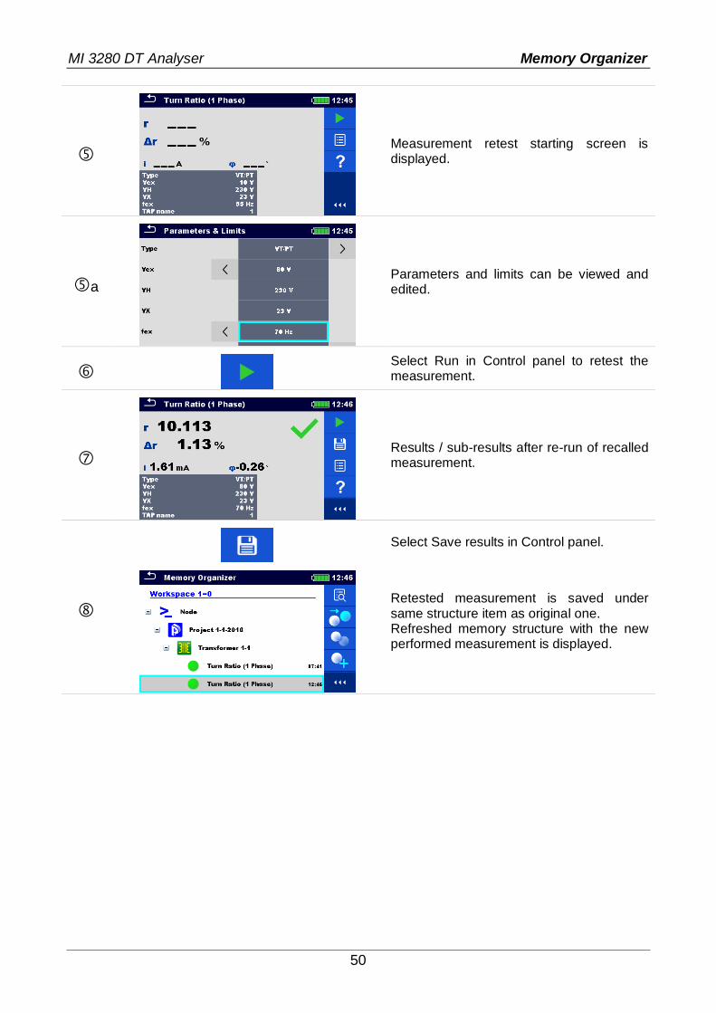
9.1.4.14 Recall and Retest selected measurement
Procedure
Select the measurement to be recalled.
Select Recall results in Control panel.
Measurement is recalled. Parameters and limits can be viewed but cannot be edited.
Select Retest in Control panel.
MI 3280 DT Analyser Memory Organizer
50
Measurement retest starting screen is displayed.
a
Parameters and limits can be viewed and edited.
Select Run in Control panel to retest the measurement.
Results / sub-results after re-run of recalled measurement.
Select Save results in Control panel.
Retested measurement is saved under same structure item as original one. Refreshed memory structure with the new performed measurement is displayed.
MI 3280 DT Analyser Single Tests
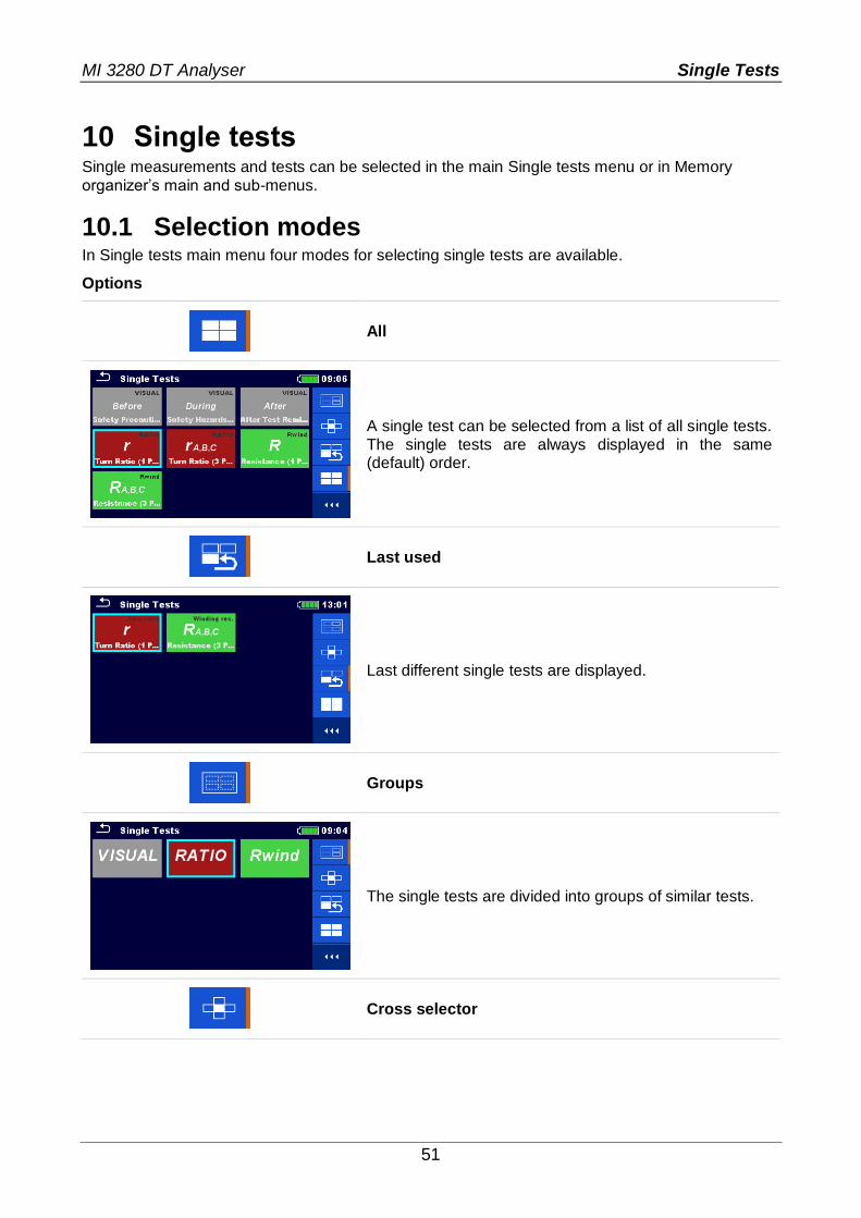
51
10 Single tests Single measurements and tests can be selected in the main Single tests menu or in Memory organizer’s main and sub-menus.
10.1 Selection modes In Single tests main menu four modes for selecting single tests are available.
Options
All
A single test can be selected from a list of all single tests. The single tests are always displayed in the same (default) order.
Last used
Last different single tests are displayed.
Groups
The single tests are divided into groups of similar tests.
Cross selector

MI 3280 DT Analyser Single Tests
52
This selection mode is the fastest for working with the keypad. Groups of single tests are organized in a row.
For the selected group all single tests are displayed and easy accessible with up /down keys.
10.1.1 Single test screens
In the Single test screens measuring results, sub-results, limits and parameters of the measurement are displayed. In addition on-line statuses, warnings and other info are displayed.
Figure 10.1: Single test screen organization of Single Phase transformer Turn Ratio measurement
Single test screen organization:
Main line: ESC touch key function name battery status clock
Control panel (available options)
Parameters (white) and limits (red)

MI 3280 DT Analyser Single Tests
53
Result field: main result(s) sub-result(s) PASS / FAIL indication number of screens
Warning symbols and message field
10.1.2 Setting parameters and limits of single tests
Procedure
Select the test or measurement. The test can be entered from:
Single tests menu or Memory organizer menu once the
empty measurement was created under selected structure.
Select Parameters in Control panel.
Select parameter to be edited or limit to be set.
on
Set parameter / limit value.
a on
Enter Set value menu.
Accepts the new parameters and limit values.

MI 3280 DT Analyser Single Tests
54
10.1.3 Setting parameters through scrollable list
Most of parameters are settable through scrollable list: Type, Vex, fex, TAP name and limit (r).
Select the test or measurement. The test can be entered from:
Single tests menu or Memory organizer menu once the
empty measurement was created in selected object structure.
Parameters and limits
Select parameter you want to edit or limit you want to set.
Set parameter value by selecting it from the list.
Accepts the new parameters and limits values.
10.1.4 Setting parameters through keyboard
Some parameters are settable through keyboard because and they can have custom value. These parameters are VH and VX.
Select the test or measurement. The test can be entered from:
Single tests menu or Memory organizer menu once the
empty measurement was created in selected object structure.

MI 3280 DT Analyser Single Tests
55
Parameters and limits
Select parameter you want to edit. Please note that only VH and VX parameters are editable
through the keyboard.
If you want to clear the field press .
When you entered a value press to confirm it.
Accepts the new parameters and limits values.
10.1.5 Single test result screen
Figure 10.2: Single test result screen - Example of Single Phase transformer Turn Ratio measurement
Options (after measurement is finished)
Starts a new measurement.
Saves the result.
A new measurement was selected and started from a Structure object in the structure tree:
the measurement will be saved under the selected Structure object.
A new measurement was started from the Single test main menu:
saving under the last selected Structure object will be offered by default. The user can select another Structure object or create a new Structure object.

MI 3280 DT Analyser Single Tests
56
By pressing the key in Memory organizer menu the measurement is saved under selected location.
An empty measurement was selected in structure tree and started:
the result(s) will be added to the measurement. The measurement will change its status from ‘empty’ to ‘finished’.
An already carried out measurement was selected in structure tree, viewed and then restarted:
a new measurement will be saved under the selected Structure object.
Opens help screens.
Opens menu for changing parameters and limits of selected measurements. Refer to chapter 10.1.2 Setting parameters and limits of single tests for more information how to change measurement parameters and limits.
on
long on
Enters cross selector to select test or measurement.
10.1.6 Recall single test result screen
Figure 10.3: Recalled results of selected measurement - Example of 4 -pole measurement recalled results
Options
Retest Enters starting screen for a new measurement.
Opens menu for changing parameters and limits of selected measurements. Refer to chapter 10.1.2 Setting parameters and limits of single tests for more information how to change measurement parameters and limits.
on

MI 3280 DT Analyser Single Tests
57
10.1.7 Single test (Visual Test) screens
Visual Test can be treated as a special class of tests. Items to be visually checked are displayed. In addition on-line statuses and other information are displayed.
Item
Status fields
Options
Selected Visual Test Overall status
Figure 10.4: Visual Test screen organisation
10.1.8 Single test (Visual Test) start screen
Figure 10.5: Visual Test screen organisation
Options (before Visual Test, screen was opened in Memory organizer or from Single test main menu)
Starts the Visual Test
Opens help screens.
Opens options in control panel / expands column.

MI 3280 DT Analyser Single Tests
58
10.1.9 Single test (Visual Test) screen during test
Figure 10.6: Visual Test screen during test
Options (during test)
Selects item
Applies a pass to the selected item or group of items.
Applies a fail to the selected item or group of items.
Clears status in selected item or group of items.
Applies a checked status to the selected item or group of items.
on A status can be applied.
Goes to the result screen.

MI 3280 DT Analyser Single Tests
59
10.1.10 Single test (Visual Test) result screen
Figure 10.7: Visual Test result screen
Options (after Visual Test is finished)
Starts a new Visual Test.
Saves the result.
A new Visual Test was selected and started from a Structure object in the structure tree:
- The Visual Test will be saved under the selected Structure object.
A new Visual Test was started from the Single test main menu:
- Saving under the last selected Structure object will be offered by default. The user can select another Structure object or create a new
Structure object. By pressing the key in Memory organizer menu the Visual Test is saved under selected location.
An empty Visual Test was selected in structure tree and started:
- The result(s) will be added to the Visual Test. The Visual Test will change its status from ‘empty’ to ‘finished’.
An already carried out Visual Test was selected in structure tree, viewed and then restarted:
A new measurement will be saved under the selected Structure object.
MI 3280 DT Analyser Single Tests
60
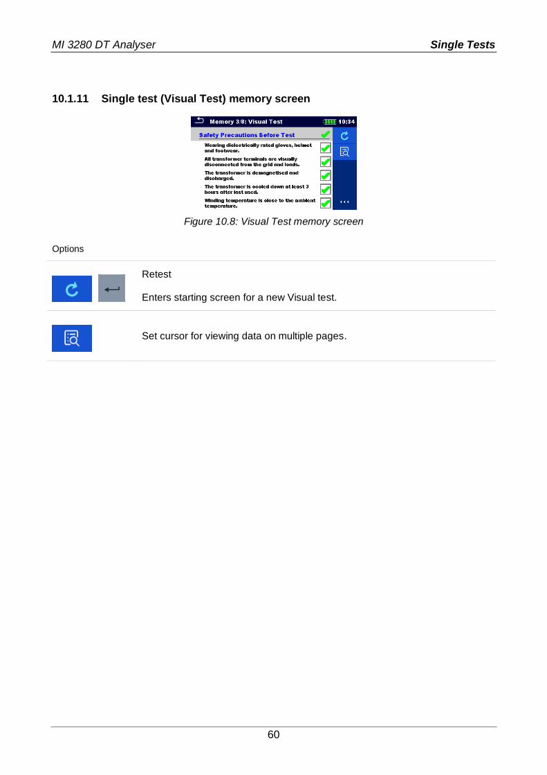
10.1.11 Single test (Visual Test) memory screen
Figure 10.8: Visual Test memory screen
Options
Retest Enters starting screen for a new Visual test.
Set cursor for viewing data on multiple pages.

MI 3280 DT Analyser Tests and Measurements
61
11 Tests and Measurements
11.1 Visual tests Visual tests are used as guidance to maintain safety standards prior/during/after testing the transformer. To use those visual tests please select VISUAL under Single tests. Visual tests are prepared to make all safety checks before starting the transformer tests, during transformer tests and after transformer tests.
Figure 11.1: Visual Test menu
Options
Pass
Fail
Clear
Checked
Safety Precautions Before Test
No. Description Values
1 Wearing dielectrically rated gloves, helmet and footwear. Comment: To protect the user from electric shock it is necessary for him/her to wear all necessary protection equipment.
Pass/Fail/Clear/Checked
2
All transformer terminals are visually disconnected from the grid and loads. Comment: Before starting the measurement, it is necessary to visually check on all terminals, if the transformer is disconnected from the grid and all connected loads. Pay attention that the load can become a voltage source.
Pass/Fail/Clear/Checked
3 The transformer is demagnetized and discharged. Comment: Eliminate all reasons that transformer can start to generate voltage for whatever reason.
Pass/Fail/Clear/Checked
4
The transformer is cooled down at least 3 hours after last used. Comment: When measuring winding resistance this must be done at known temperature, which is ambient temperature. This is especially important for large transformers.
Pass/Fail/Clear/Checked
5 The winding temperature is close to the ambient temperature. Comment: If transformer is small you can leave it disconnected long enough for winding temperature to reach the ambient temperature.
Pass/Fail/Clear/Checked
6 Connect all unused test leads to ground. Comment: Some of three phase transformers have only 6 terminals, so 2
Pass/Fail/Clear/Checked

MI 3280 DT Analyser Tests and Measurements
62
unused test leads must be connected to ground.
Table 11.2: Visual Test - Safety Precautions Before Test
Safety Hazards During Test
No. Description Values
1 Touching test leads or clips during tests can cause an electric shock. Pass/Fail/Clear/Checked
2 Disconnecting test leads during tests can result in hazardous electric shock and equipment damage.
Pass/Fail/Clear/Checked
Table 11.3: Visual Test – Hazards During Test
After Test Reminder
No. Description Values
1 All test leads promptly removed after the test is completed. Pass/Fail/Clear/Checked
Table 11.4: Visual Test – After Test Reminder
Visual Test procedure:
Select Visual function. Start the Visual Test (press the Run key). Perform the Visual Test. Apply appropriate ticker(s) to items. End Visual Test. Save results (optional).
Figure 11.5: Examples of Visual Test results

MI 3280 DT Analyser Tests and Measurements
63
11.2 Turn ratio [r, rA,rB,rC]
11.2.1 Single-phase transformers
Turn ratio (r) of single-phase transformer can be measured by setting Type of the transformer (CT – current transformer or VT/PT – voltage/power transformer) first, followed by entering rated primary and secondary winding voltage/current for reference turn ratio (r ref) calculation and setting excitation voltage and frequency. The measurement of the two (CT and VT/PT) is similar, but not the same. Major difference between the two of them is in connection diagram and in set of selectable excitation voltages (Vex). When measuring CT the set of excitation voltage is from 1 V to 10 V (with 1 V resolution) and when measuring VT/PT you can select excitation voltage between 1 V, 5 V, 10 V, 40 V and 80 V. Please set parameter transformer Type prior measurement and check specific connections for both options. Excitation voltage (Vex) and excitation frequency (fex) parameters are used to set the properties of testing voltage, which is applied to the transformer to test turn ratio. It is useful to use Vex as high as possible (Vex = 80 V), because the accuracy will be higher in comparison with low excitation voltages. This setting must not be in conflict with any safety procedures or with transformer maximum allowable applied voltage. Check these values prior starting the measurement. If you do not have specific reason to operate at specific excitation frequency, it is highly recommended to set fex to 70 Hz. At this frequency, there is minimum influence of electromagnetic disturbances when measuring near the 50 Hz or 60 Hz grid. Transformers are usually tested at same or higher frequencies than is the operating frequency of the transformer. For pass/fail notification the high voltage winding rated voltage (VH), the low voltage winding rated voltage (VX) and turn ratio deviation limit must be set. These parameters are used to show pass/fail notification after the measurement is finished. If you do not want to set these
parameters set limit (r) to Off. Additionally excitation current (i) is measured and phase deviation is calculated. Phase deviation is a phase difference of first harmonic (@fex) between high voltage winding (H) voltage and low voltage winding (X) voltage.
Parameter Description Values Unit
Type Transformer type VT/PT: voltage/power transformer CT: current transformer
-
Vex Excitation voltage 1, 5, 10, 40 or 80 (for VT/PT) 1 … 10 (for CT)
V
fex Excitation frequency 55, 65 or 70 Hz
VH High voltage (H) winding rated voltage of VT/PT Custom (set through keyboard) V
VX Low voltage (X) winding rated voltage of VT/PT Custom (set through keyboard) V
IH High current winding rated current of CT Custom (set through keyboard) A
IX Low current winding rated current of CT Custom (set through keyboard) A
rref Reference turn ratio of (VT/PT and CT) Calculated -
TAP name TAP name or tap position 1 … 32 -
Limit Description Values Unit
Limit (r) Turn ratio deviation (r) limit Off, 0.2, 0.5, 1, 2, 5 or 10 %
Table 11.6: Single phase transformer turn ratio measurements parameters and limits

MI 3280 DT Analyser Tests and Measurements
64
11.2.1.1 Voltage / Power transformers (VT/PT)
To measure single-phase voltage/power transformer (VT/PT) you need to connect H1|H0 connector (red terminal: black and yellow wires) and X1|H0 connector (grey terminal; black and yellow wires) to appropriate MI 3280 socket as shown in Figure 11.7.
Figure 11.7: Single-phase VT/PT transformer turn ratio measurement connection
VH and VX parameters are used to calculate reference turn ratio (rref) which is then used for
calculation of the turn ratio deviation (r). Pass/fail notification is based on r and Limit (r):
VVX
VVHrref
VVVV
VVVVr
mXmX
mHmH
01
01
%100
ref
ref
r
rrr
where: VH ...................................... High voltage winding (H) rated voltage VX ...................................... Low voltage winding (X) rated voltage VH1m - VH0m ........................... High voltage winding (H) measured voltage VX1m - VX0m ........................... Low voltage winding (X) measured voltage r .......................................... Measured turn ratio rref ........................................ Reference turn ratio
r ........................................ Turn ratio deviation [%]
Limit (r) ............................ Turn ratio deviation tolerance [%] Phase deviation is an angle difference between first harmonic (@fex) of excitation voltage
(high voltage winding (VH) ) and a measured voltage on low voltage winding (VX):
)()( VXVH
where:
(VH) .................................. Phase of high voltage winding (H) voltage
(VX) .................................. Phase of low voltage winding (X) voltage
.......................................... Phase deviation

MI 3280 DT Analyser Tests and Measurements
65
Figure 11.8: Single-phase VT/PT transformer turn ratio measurement menu
Test parameters for Single-phase VT/PT turn ratio measurement: Type VT/PT
Vex Set excitation voltage: 1 V, 5 V, 10 V, 40 V or 80 V
fex Set excitation frequency: 55 Hz, 65 Hz or 70 Hz
VH Set high voltage winding (H) rated voltage: Custom (Set through keyboard)
VX Set low voltage winding (X) rated voltage: Custom (Set through keyboard)
Limit (r) Set limit for pass/fail indicator: Off, 0.2 %, 0.5 %, 1 %, 2 %, 5 % or 10 %
TAP name Set TAP name: 1 … 32
Single-phase VT/PT turn ratio measurement procedure:
Connect test leads H0|H1 and X0|X1 to corresponding MI 3280 sockets. Connect VT/PT transformer like shown in Figure 11.7. Select turn ratio measurement (r) for single-phase transformer. Set Type parameter to VT/PT. Set transformer parameters VH and VX from transformer plate. Set test parameters Vex and fex.
Set turn ratio deviation limit(r). Set TAP name (if measuring multiple TAP transformer).
Press the Run key to start the measurement. Wait until the test result is displayed on the screen. Save results (optional).
Figure 11.9: Single-phase VT/PT transformer turn ratio measurement results
Notes: Consider displayed warnings when starting the measurement! If error notification appears on screen at the beginning of the measurement (for
example V(H1H2) > 10.0V), transformer might be supplied with auxiliary power source. Inspect what might be the cause for that error, eliminate the fault and try again.
If overvoltage protection notification appears on screen, first lower the excitation voltage and try again. If overvoltage protection is perpetually popping up, H and X clamps are not connected properly! Check connection any try again.
If overcurrent protection notification appears on screen, lower the excitation voltage and try again.

MI 3280 DT Analyser Tests and Measurements
66
11.2.1.2 Current transformers (CT)
To measure single-phase current transformer (CT) you need to connect H1|H0 connector (red terminal: black and yellow wires) and X1|H0 connector (grey terminal; black and yellow wires) to appropriate MI 3280 socket like shown in Figure 11.10. Please note that when measuring current transformer, high voltage winding is connected to H clamps and low voltage winding to X clamps.
Figure 11.10: Single-phase CT transformer turn ratio measurement connection
Reference turn ratio (rref) is used to generate pass/fail notification after turn ratio is measured
and based on value limit (r):
AIX
AIHrref
VVVV
VVVVr
mXmX
mHmH
01
01
%100
ref
ref
r
rrr
where: IH ........................................ High current winding (H) rated current IX ........................................ Low current winding (X) rated current VH1m - VH0m ........................... High voltage winding (H) voltage VX1m - VX0m ........................... Low voltage winding (X) voltage r .......................................... Measured turn ratio rref ........................................ Reference turn ratio
r ........................................ Turn ratio deviation [%]
Limit (r) ............................. Turn ratio deviation tolerance [%]

MI 3280 DT Analyser Tests and Measurements
67
Phase deviation is angle difference between first harmonic (@fex) between excitation voltage
(high voltage winding (VH) ) and low voltage winding measured voltage (VX):
)()( VXVH
where:
(VH) .................................. Phase (at fex) of high voltage winding (H) excitation voltage
(VX) .................................. Phase (at fex) of low voltage winding (X) voltage
.......................................... Phase deviation
Figure 11.11: Single-phase CT transformer turn ratio measurement menu
Warning:
When measuring small currents transformers (CTs), it is recommended to start with low Vex (1 V), to prevent the core saturation at higher voltages. After successfully completing the first measurement, gradually increase the Vex and repeat measurements to get better accuracy of results. If the transformer core become saturated during measurement this will result in excitation
current (i) that is NOT in proportion with Vex and will also result in phase () that vary almost randomly. In that case please treat such result as NOT valid, use previous result as valid or repeat the test with lower Vex. Compare results with initial result (at Vex = 1 V) as a reference.
Test parameters for single-phase CT turn ratio measurement: Type CT
Vex Set excitation voltage: 1 V …10 V
fex Set excitation frequency: 55 Hz, 65 Hz or 70 Hz
IH Set high current winding (H) rated current: Custom (Set through keyboard)
IX Set low current winding (X) rated current: Custom (Set through keyboard)
limit (r) Set limit for pass/fail indicator: Off, 0.2 %, 0.5 %, 1 %, 2 %, 5 % or 10 %
TAP name Set TAP name: 1 … 32

MI 3280 DT Analyser Tests and Measurements
68
Single-phase CT turn ratio measurement procedure:
Connect test leads H0|H1 and X0|X1 to corresponding MI 3280 sockets. Connect CT transformer like shown in Figure 11.10. Select turn ratio measurement (r) for single-phase transformer. Set Type parameter to CT. Set parameters IH and IX (transformer rated primary/secondary current from
transformer plate). Set test parameters Vex and fex (start with low Vex, 1 V is a good starting point).
Set turn ratio deviation limit(r). Set TAP name (if measuring multiple TAP transformer). Press the Run key to start the measurement. Wait until the test result is displayed on the screen. Repeat measurement with increased Vex, to improve measurement accuracy, and
compare measurement results with initial one, until core saturation is detected. If excitation current (i) is not proportional with Vex or other anomalies are found in
the result (non-consistency in phase) treat this result as invalid. It is recommended to use maximum possible Vex (watch also the CT’s maximum
current). Save results (optional).
Figure 11.12: Single phase CT transformer turn ratio measurement results:
limit(r) = 0.2 % (left), limit(r) = 10 % (right)
Notes: Consider displayed warnings when starting the measurement! If error notification appears on screen at the beginning of the measurement (for
example V(H1H2) > 10.0V), transformer might be supplied with auxiliary power source. Inspect what might be the cause for that error, eliminate the fault and try again.
If overvoltage protection notification appears on screen, first lower the excitation voltage and try again. If overvoltage protection is perpetually popping up, H and X clamps are not connected properly! Check connection any try again.
If overcurrent protection notification appears on screen, lower the excitation voltage and try again.

MI 3280 DT Analyser Tests and Measurements
69
11.2.2 Three-phase transformers
For turn ratio of three-phase transformer rA,rB,rC measurement should be selected. Measurement parameterization must start with selection of the IEC Vector Group (see
Appendix D – Vector groups for details), which is fundamental parameter. Make sure it is
set correctly or the results will be wrong. The Vector Group selection is divided into two sections. First select H-X Configuration, which will ease the further selection by limiting the amount of choices for specific Vector Group. Excitation voltage (Vex) and excitation frequency (fex) parameters define voltage/frequency
of the signal, which will be applied to the three-phase transformer to test the turn ratio. MI 3280 DT Analyser has a single AC source, so multiple phases of the three phase transformer are measured sequentially (phase A, B and C). It is suggested to keep Vex as high as possible (Vex = 80 V), if this is not in conflict with safety procedures, testing procedure or
violating transformer maximum voltage. It is highly recommended to set excitation frequency (fex) to 70 Hz, if no specific reason exists to set differently This frequency is the most suitable choice for both 50 Hz and 60 Hz grid system. For pass/fail notification, the high voltage winding rated voltage (VH) and the low voltage
winding rated voltage (VX) plus the turn ratio deviation limit (limit (r)) must be set. Those
parameters are used to calculate turn ratio deviation (r) and for showing pass/fail
notification after the measurement is finished. Set limit (r) to Off to disable pass/fail notification.
Parameter Description Values Unit
Configuration Select Configuration of transformer D-d, D-y, D-z, Y-y, Y-d, Y-z -
D-d Select D-d the Vector Group (if used) Dd0, Dd2, Dd4, Dd6, Dd8 orDd10 -
D-y Select D-y the Vector Group (if used) Dy1, Dyn1, Dy5, Dyn5, Dy7, Dyn7, Dy11 or Dyn11
-
D-z Select D-z the Vector Group (if used) Dz0, Dzn0, Dz2, Dzn2, Dz4, Dzn4, Dz6, Dzn6, Dz8, Dzn8, Dz10 or Dzn10
-
Y-y Select Y-y the Vector Group (if used) Yy0, YNy0, Yyn0, YNyn0, Yy6, YNy6, Yyn6 or YNyn6
-
Y-d Select Y-d the Vector Group (if used) Yd1, YNd1, Yd5, YNd5, Yd7, YNd7, Yd11 or YNd11
-
Y-z Select Y-z the Vector Group (if used) Yz1, Yzn1, Yz5, Yzn5, Yz7, Yzn7, Yz11 or Yzn11
-
Vex Excitation voltage 1, 5, 10, 40 or 80 (for VT/PT) V
fex Excitation frequency 55, 65 or 70 Hz
VH High voltage (H) winding rated voltage Custom (set through keyboard) V
VX Low voltage (X) winding rated voltage Custom (set through keyboard) V
TAP name TAP name or tap position 1 … 32 -
Limit Description Values Unit
Limit (rA,B,C ) Turn ratio deviation (rA,B,C) limit Off, 0.2, 0.5, 1, 2, 5 or 10 %
Table 11.1: Three phase transformer turn ratio measurements parameters and limits

MI 3280 DT Analyser Tests and Measurements
70
11.2.2.1 Voltage / Power transformers (VT/PT)
To measure three-phase voltage/power transformer you need to connect H1|H0 connector (red terminal: black and yellow wires), H2|H3 connector (red terminal: green and white wires), X1|X0 connector (grey terminal: black and yellow wires) and X2|X3 connector (grey terminal: green and white wires) to appropriate MI 3280 DT Analyser socket like shown in Figure 11.13.
Figure 11.13: Turn ratio measurement of three-phase transformer
VH and VX parameters are used to calculate reference turn ratio (rref) of one phase which is used to calculate the turn ratio deviation and to generate pass/fail notification based on
rA,B,C and Limit (r):
VVX
VVHrref
VVVV
VVVVr
mCBAXmCBAX
mCBAHmCBAH
CBA
0,,1,,
0,,1,,
,,
where: VH ...................................... Transformer high voltage windings (H) rated voltage VX ...................................... Transformer low voltage windings (X) rated voltage
......................................... Turn ratio constant, related to selected Vector Group VH A,B,C 1m - VH A,B,C 0m ............ High voltage side (H) measured voltage of phases A, B and C VX A,B,C 1m - VX A,B,C 0m ............ Low voltage side (X) measured voltage of phases A, B and C rA,rB,rC .................................. Measured turn ratio of phases A, B and C rref ........................................ Reference turn ratio
rA,B,C .................................. Turn ratio deviation of phases A, B and C [%]
Limit (r) ............................. Turn ratio deviation tolerance [%]
%100,,
,,
ref
refCBA
CBAr
rrr

MI 3280 DT Analyser Tests and Measurements
71
Phase deviation is angle difference between first harmonic (@fex) of excitation voltage of
high voltage winding (VH) and measured voltage of low voltage winding (VX):
)()( ,,,,,, CBACBACBA VXVH
where:
(VHA,B,C) ............................ Phase (@fex) of high voltage winding (H) voltage
(VXA,B,C) ............................ Phase (@fex) of low voltage winding (X) voltage
A,B,C .................................... Phase deviation
Figure 11.14: Three-phase transformer measurement menu: turn ratio (left), excitation current and phase deviation (right)
Test parameters for three-phase transformer turn ratio measurement: Configuration Set Configuration of transformer: D-d, D-y, D-z, Y-y, Y-d, Y-z
Vector Group Set Vector Group: (See Appendix D – Vector groups for details)
VH Set high voltage winding (H) rated voltage: Custom (Set through keyboard)
VX Set low voltage winding (X) rated voltage: Custom (Set through keyboard)
Vex Set excitation voltage: 1 V, 5 V, 10 V, 40 V or 80 V
fex Set excitation frequency: 55 Hz, 65 Hz or 70 Hz
Limit (r) Set limit for pass/fail indicator: Off, 0.2 %, 0.5 %, 1 %, 2 %, 5 % or 10 %
TAP name Set TAP name: 1 … 32
Three-phase transformer turn ratio measurement procedure:
Connect test leads H0|H1, H2|H3, X0|X1 and X2|X3 to corresponding MI 3280 DT Analyser sockets.
Connect three-phase transformer. Select turn ratio measurement (rA,B,C) for three-phase transformer. Set parameters Configuration and Vector Group. Set transformer parameters VH and VX from transformer plate. Set test parameters Vex and fex.
Set turn ratio deviation Limit(rA,rB,rC). Set TAP name (if measuring multiple TAP transformer). Press the Run key to start the measurement. Wait until the test result is displayed on the screen. Toggle result screens with left/right cursor keys. Save results (optional).

MI 3280 DT Analyser Tests and Measurements
72
Figure 11.15: Three-phase transformer results: turn ratio (left), excitation current and phase
deviation (right): limit(r) = 5 %
Figure 11.16: Three-phase transformer results: turn ratio (left), excitation current and phase
deviation (right): limit(r) = 10 %
Notes:
Consider displayed warnings when starting the measurement! If error notification appears on screen at the beginning of the measurement (for
example V(H1-H2) > 10.0V), transformer might be supplied with auxiliary power source. Inspect what might be the cause for that error, eliminate the fault and try again.
If overvoltage protection notification appears on screen, first lower the excitation voltage and try again. If overvoltage protection is perpetually popping up, H and X clamps are not connected properly! Check connection any try again.
If overcurrent protection notification appears on screen, lower the excitation voltage and try again.

MI 3280 DT Analyser Tests and Measurements
73
11.3 Winding resistance [R, RA,RB,RC]
11.3.1 Single-phase transformers
Winding resistance of single-phase transformer can be measured by selecting single test R. Single-phase transformer winding resistance testing is divided into two parts: measurement of resistance of high voltage winding (H) and/or of low voltage winding (X) regarding to parameter Side to measure. The complete test can be made by setting parameter Side to measure to Both. Connection is shown in Figure 11.18. MI 3280 DT Analyser has a single current source. Winding resistances must be measured sequentially (one at a time). Progress indicator on the screen is shown in Figure 11.17.
Figure 11.17: Progress indicator at single-phase transformer winding resistance measurement: H side testing in progress (left), X side testing in progress (left)
Winding resistance is measured by applying a stable DC current to the appropriate winding (or winding combination) which to be measured. After detecting steady state of winding current, the voltage is measured and resistance is calculated by Ohm’s law. When measurement is finished the transformer inductance is discharged with internal circuitry and the energy is redirected back to the battery. Such energy recuperation is extending the autonomy of the battery.
Parameter Description Values Unit
TAP name TAP name or tap position 1 … 32 -
Side to measure
Side of the transformer to be measured H: high voltage winding only X. low voltage winding only Both: both windings
-
Table 11.2: Single-phase transformer winding resistance measurements

MI 3280 DT Analyser Tests and Measurements
74
11.3.2 Testing, connection and results
To measure winding resistance of a single-phase transformer you need to connect H1|H0 connector (red terminal: black and yellow wires) and/or X1|H0 connector (grey terminal;
black and yellow wires) to appropriate MI 3280 DT Analyser socket, like shown in Figure 11.18. Both pair of probes (H and X) can be connected, nevertheless which side is to be measured. When steady state of current and voltage is detected, winding resistance is calculated based on Ohm’s law:
AI
VVVRH
dc
mHmH 01
AI
VVVRX
dc
mXmX 01
where: VH1m - VH0m ........................... High voltage winding (H) voltage VX1m - VX0m ........................... Low voltage winding (X) voltage Idc ........................................ Excitation DC current RH ...................................... High voltage winding (H) resistance RX ....................................... Low voltage winding (X) resistance
Figure 11.18: H and X side winding resistance measurement of single-phase transformer
Figure 11.19: Single-phase transformer winding resistance measurement menu
Test parameters for single-phase transformer winding resistance measurement: TAP name Set TAP name: 1 … 32
Side to meas. Set windings to measure: H, X, Both

MI 3280 DT Analyser Tests and Measurements
75
Single-phase transformer winding resistance measurement procedure:
Connect test leads H0|H1 and X0|X1 to corresponding MI 3280 DT Analyser sockets.
Connect single-phase transformer (VT/PT or CT). Select winding resistance measurement (R) for single-phase transformer. Set TAP name (if measuring multiple TAP transformer). Set parameter Side to measure. Press the Run key to start the measurement. Wait until the test result is displayed on the screen and discharge is finished. Save results (optional).
Figure 11.20: Single-phase transformer winding measurement results
Warning:
Please do not disconnect test leads during testing. Wait until results are shown on the screen and discharge is finished. Removing clamps prior that can result in high voltage spike, potentially hazardous electric shock and a permanent damage of testing equipment.
Notes:
Consider displayed warnings when starting the measurement! If error notification appears on screen at the beginning of the measurement (for
example V(H1-H2) > 10.0V), transformer might be supplied with auxiliary power source. Inspect what might be the cause for that error, eliminate the fault and try again.
If error notification appears on screen during the measurement (for example I(X1-X2) < 1 mA), at least one clip indicated in the message is disconnected or too high winding resistance is detected. Inspect what might be the cause for that error, eliminate the fault and try again.

MI 3280 DT Analyser Tests and Measurements
76
11.3.3 Three-phase transformers
Winding resistance of three-phase transformer can be measured by selecting three-phase winding resistance measurement (RA,RB,RC). Measurement parameterization must start with
selection of the IEC Vector Group (see Appendix D – Vector groups for details), which is
fundamental parameter. Make sure it is set correctly or the results will be wrong or misleading. The Vector Group selection is divided into two sections. First select H-X Configuration, which will ease the further selection by limiting the amount of choices for specific Vector Group.
MI 3280 DT Analyser is using single current source so all winding resistance of the transformer are measured sequentially in the following order: RA, RB and RC. Measurements can be selected with Side to Measure parameter (H side only, X side only or both sides). During testing of the transformer, instantaneous current is shown on the screen. These intermediate results are for information purposes only and are not presenting final result. When the whole transformer is tested and the resistances are calculated, results will be shown on the screen.
Figure 11.21: Progress indicator at three-phase transformer winding resistance measurement: first (1/6) test in progress (left) and last (6/6) test in progress (right)
Table 11.3: Three-phase resistance winding resistance measurements
Parameter Description Values Unit
Configuration Select Configuration of transformer D-d, D-y, D-z, Y-y, Y-d, Y-z -
D-d Select D-d the Vector Group (if used) Dd0, Dd2, Dd4, Dd6, Dd8, Dd10 -
D-y Select D-y the Vector Group (if used) Dy1, Dyn1, Dy5, Dyn5, Dy7, Dyn7, Dy11, Dyn11
-
D-z Select D-z the Vector Group (if used) Dz0, Dzn0, Dz2, Dzn2, Dz4, Dzn4, Dz6, Dzn6, Dz8, Dzn8, Dz10, Dzn10
-
Y-y Select Y-y the Vector Group (if used) Yy0, YNy0, Yyn0, YNyn0, Yy6, YNy6, Yyn6, YNyn6
-
Y-d Select Y-d the Vector Group (if used) Yd1, YNd1, Yd5, YNd5, Yd7, YNd7, Yd11, YNd11
-
Y-z Select Y-z the Vector Group (if used) Yz1, Yzn1, Yz5, Yzn5, Yz7, Yzn7, Yz11, Yzn11
-
TAP name TAP name or tap position 1 … 32 -
Side to measure
Side of the transformer to be measured H: high voltage windings only X. low voltage windings only Both: high and low voltage windings
-

MI 3280 DT Analyser Tests and Measurements
77
11.3.3.1 Testing, connection and results
To measure three-phase voltage/power transformer you need to connect H1|H0 connector (red terminal: black and yellow wires), H2|H3 connector (red terminal: green and white wires), X1|X0 connector (grey terminal: black and yellow wires) and X2|X3 connector (grey terminal: green and white wires) to appropriate MI 3280 DT analyser socket like shown in Figure 11.22.
Figure 11.22: Winding resistance measurement of three-phase transformer
Figure 11.23: Three-phase transformer winding resistance measurement menu
Test parameters for three-phase transformer winding resistance measurement: Configuration Set Configuration of transformer: D-d, D-y, D-z, Y-y, Y-d or Y-z
Vector Group Set Vector Group: (See Appendix D – Vector groups for details)
TAP name Set TAP name: 1 … 32
Side to meas. Set side of transformer to be measured: H, X or Both
Three-phase transformer winding resistance measurement procedure:
Connect test leads H0|H1, H2|H3, X0|X1 and X2|X3 to corresponding MI 3280 DT
Analyser sockets. Connect three-phase transformer like shown in Figure 11.22. Select winding resistance measurement of three-phase transformer (RA,B,C). Set parameter Configuration and Vector Group. Set TAP name (if measuring multiple TAP transformer). Set parameter Side to measure. Press the Run key to start the measurement. Wait until the test result is displayed on the screen and discharge is finished. Save results (optional).

MI 3280 DT Analyser Tests and Measurements
78
Figure 11.24: Three-phase transformer winding resistance measurement results
Warning:
Please do not disconnect test leads during testing. Wait until results are shown on the screen and discharge is finished. Removing clamps prior that, can result in high voltage spike, potentially hazardous electric shock and a permanent damage of testing equipment.
Notes:
Consider displayed warnings when starting the measurement! If error notification appears on screen at the beginning of the measurement (for
example V(H1-H2) > 10.0V), transformer might be supplied with auxiliary power source. Inspect what might be the cause for that error, eliminate the fault and try again.
If error notification appears on screen during the measurement (for example I(X1-X2) < 1 mA), at least one clip indicated in the message is disconnected or too high winding resistance is detected. Inspect what might be the cause for that error, eliminate the fault and try again.

MI 3280 DT Analyser Auto Sequence®
79
12 Auto Sequence® Pre-programmed sequences of measurements can be carried out in Auto Sequence menu. The sequence of measurements, their parameters and flow of the sequence can be programmed. The results of an Auto Sequence can be stored in the memory together with all related information. Auto Sequence can be pre-programmed on PC with the Metrel ES Manager software and uploaded to the instrument. On the instrument, parameters and limits of individual single test in the Auto Sequence can be changed / set.
12.1 Selection of Auto Sequence®
The Auto Sequence list from Auto Sequence groups menu should be selected first. Refer to chapter 8.8 Auto Sequence® groups for more details. The Auto Sequence to be carried out can then be selected from the Main Auto Sequence menu. This menu can be organized in structural manner with folders, sub-folders and Auto Sequence.
Figure 12.1: Main Auto Sequence menu
Options
Enters menu for more detail view of selected Auto Sequence. This option should also be used if the parameters / limits of the selected Auto Sequence have to be changed. Refer to chapter 12.2.1 Auto Sequence view menu for more information.
Starts the selected Auto Sequence. The instrument immediately starts the Auto Sequence.

MI 3280 DT Analyser Auto Sequence®
80
12.2 Organization of Auto Sequence® An Auto Sequence is divided into three phases:
Before starting the first test the Auto Sequence view menu is shown (unless it was started directly from the Main Auto Sequence menu). Parameters and limits of individual measurements can be set in this menu.
During the execution phase of an Auto Sequence, pre-programmed single tests are carried out. The sequence of single tests is controlled by pre-programmed flow commands.
After the test sequence is finished the Auto Sequence result menu is shown. Details of individual tests can be viewed and the results can be saved to Memory organizer.
12.2.1 Auto Sequence view menu
In the Auto Sequence view menu, the header and the single tests of selected Auto Sequence are displayed. The header contains the name and description of the Auto Sequence. Before starting the Auto Sequence, test parameters / limits of individual measurements can be changed. Auto Sequence view menu (header is selected)
Name of Auto Sequence Description of Auto Sequence
Header
Single
Test
Options
Figure 12.2: Auto Sequence view menu – header selected
Options
Starts the Auto Sequence.

MI 3280 DT Analyser Auto Sequence®
81
Auto Sequence view menu (measurement is selected)
Name of Auto SequenceParameters and limits of
selected single test
Header
Single
Test
Options
Figure 12.3: Auto Sequence view menu – measurement selected
Options
Selects single test.
on
Opens menu for changing parameters and limits of selected measurements. Refer to chapter 10.1.2 Setting parameters and limits of single tests for more information how to change measurement parameters and limits.
Indication of Loops
The attached ‘x2’ at the end of single test name indicates that a loop of single tests is programmed. This means that the marked single test will be carried out as many times as the number behind the ‘x’ indicates. It is possible to exit the loop before, at the end of each individual measurement.

MI 3280 DT Analyser Auto Sequence®
82
12.2.2 Step by step executions of Auto Sequence
While the Auto Sequence is running, it is controlled by pre-programmed flow commands. Examples of actions controlled by flow commands are:
pauses during the test sequence buzzer proceeding of test sequence in regard to measured results
The actual list of flow commands is available on chapter V Description of flow commands.
Figure 12.4: Auto Sequence – example of a pause with message (text or picture)
Figure 12.5: Auto Sequence – example of a finished measurement with options for proceeding
Options (during execution of an Auto Sequence)
Proceeds to next step in the test sequence.
Repeats the measurement. Displayed result of a single test will not be stored.
Ends the Auto Sequence and goes to Auto Sequence result screen.
Exits the loop of single tests and proceeds to the next step in the test sequence.
The offered options in the control panel depend on the selected single test, its result and the programmed test flow.

MI 3280 DT Analyser Auto Sequence®
83
12.2.3 Auto Sequence result screen
After the Auto Sequence sequence is finished the Auto Sequence result screen is displayed. At the left side of the display the single tests and their statuses in the Auto Sequence are shown. In the middle of the display the header of the Auto Sequence is displayed. At the top the overall Auto Sequence status is displayed. Refer to chapter 9.1.1 Measurement statuses for more information.
Name of Auto Sequence Overall status of Auto Sequence
Single
Tests
Options
Description of
Auto SequenceStatus of
Single Test
Figure 12.6: Auto Sequence result screen
Options
Start Test
Starts a new Auto Sequence.
View results of individual measurements. The instrument goes to menu for viewing details of the Auto Sequence.
Saves the Auto Sequence results. A new Auto Sequence was selected and started from a Structure object in the structure tree:
The Auto Sequence will be saved under the selected Structure object.
A new Auto Sequence was started from the Auto Sequence main menu: Saving under the last selected Structure object will be offered by
default. The user can select another Structure object or create a
new Structure object. By pressing in Memory organizer menu the Auto Sequence is saved under selected location.
An empty measurement was selected in structure tree and started: The result(s) will be added to the Auto Sequence. The Auto
Sequence will change its overall status from ‘empty’ to ‘finished’. An already carried out Auto Sequence was selected in structure tree, viewed and then restarted:
A new Auto Sequence will be saved under the selected Structure object.

MI 3280 DT Analyser Auto Sequence®
84
Options in menu for viewing details of Auto Sequence results
Details of selected single test in Auto Sequence are displayed.
on
Opens menu for viewing parameters and limits of selected measurements. Refer to chapter 10.1.2 Setting parameters and limits of single tests for more information.
Figure 12.7: Details of menu for viewing details of Auto Sequence results
Figure 12.8: Details of single test in Auto Sequence result menu

MI 3280 DT Analyser Auto Sequence®
85
12.2.4 Auto Sequence memory screen
In Auto Sequence memory screen details of the Auto Sequence can be viewed and a new Auto Sequence can be restarted.
Figure 12.9: Auto Sequence memory screen
Options
Retest the Auto Sequence. Enters menu for a new Auto Sequence.
Enters menu for viewing details of the Auto Sequence.
MI 3280 DT Analyser Communication
86
13 Communication The instrument can communicate with the Metrel ES Manager PC software. The following action is supported:
Saved results and Tree structure from Memory organizer can be downloaded and stored to a PC.
Tree structure and Auto Sequence® from Metrel ES Manager PC software can be uploaded to the instrument.
Metrel ES Manager is PC software running on Windows 7, Windows 8, Windows 8.1 and Windows 10. There are two communication interfaces available on the instrument: USB and Bluetooth. How to establish an USB link:
Connect a PC USB port to the instrument USB connector using the USB interface cable.
Switch on the PC and the instrument. Run the Metrel ES Manager software. Set the desired communication port. (COM port is identified as “USB Serial Port”.) If not visible, make sure to install the correct USB driver (see notes). The instrument is prepared to communicate with the PC over USB.
Bluetooth communication The internal Bluetooth module enables easy communication via Bluetooth with PC and Android devices. How to configure a Bluetooth link between instrument and PC:
Switch On the instrument. On PC configure a Standard Serial Port to enable communication over Bluetooth link
between instrument and PC. Usually no code for pairing the devices is needed. Run the Metrel ES Manager software. Set the configured communication port. The instrument is prepared to communicate with the PC over Bluetooth.
Notes:
USB drivers should be installed on PC before using the USB interface. Refer to USB installation instructions available on installation CD or download the drivers from the http://www.ftdichip.com website (MI 3280 is using the FT232RL chip).
The name of correctly configured Bluetooth device must consist of the instrument type plus serial number, eg. MI 3280-12345678I.
Bluetooth communication device pairing code is NNNN.
MI 3280 DT Analyser Maintenance
87
14 Maintenance Unauthorized persons are not allowed to open the MI 3280 DT Analyser instrument. There are no user replaceable components inside the instrument. Batteries can only be replaced with certified ones and only by authorized persons.
14.1 Cleaning No special maintenance is required for the housing. To clean the surface of the instrument, use a soft cloth slightly moistened with soapy water or alcohol. Then leave the instrument to dry totally before use. Warnings:
Do not use liquids based on petrol or hydrocarbons! Do not spill cleaning liquid over the instrument!
14.2 Periodic calibration It is essential that the test instrument is regularly calibrated in order that the technical specification listed in this manual is guaranteed. We recommend an annual calibration. Only an authorized technical person can do the calibration. Please contact your dealer for further information.
14.3 Service For repairs under warranty, or at any other time, please contact your distributor.
14.4 Upgrading the instrument The instrument can be upgraded from a PC via the USB communication port. This enables to keep the instrument up to date even if the standards or regulations change. The firmware upgrade requires internet access and can be carried out from the Metrel ES Manager software with a help of special upgrading software – FlashMe that will guide you through the upgrading procedure. For more information, refer to Metrel ES Manager Help file. Note:
See chapter 13 Communication for details on USB driver installation.

MI 3280 DT Analyser Technical specifications
88
15 Technical specifications
15.1 Turn ratio measurement [r, rA, rB, rC,] Measurement principle .................................Voltage measurement
Turn ratio Excitation voltage Measuring range Resolution Uncertainty
r, rA, rB, rC
80 V
0,8000 … 9,9999 0,0001 (0,2% of reading + 2 digits)
10,000 … 99,999 0,001 (0,2% of reading + 2 digits)
100,00 … 999,99 0,01 (0,2% of reading + 2 digits)
1000,0 … 1999,9 0,1 (0,5% of reading + 2 digits)
2000,0 … 3999,9 0,1 (0,5% of reading + 2 digits)
4000,0 … 8000,0 0,1 (1,0% of reading + 2 digits)
40 V
0,8000 … 9,9999 0,0001 (0,2% of reading + 2 digits)
10,000 … 99,999 0,001 (0,2% of reading + 2 digits)
100,00 … 999,99 0,01 (0,2% of reading + 2 digits)
1000,0 … 1999,9 0,1 (0,5% of reading + 2 digits)
2000,0 … 3999,9 0,1 (0,5% of reading + 2 digits)
4000,0 … 8000,0 0,1 Indication only
10 V
0,8000 … 9,9999 0,0001 (0,2% of reading + 2 digits)
10,000 … 99,999 0,001 (0,2% of reading + 2 digits)
100,00 … 999,99 0,01 (0,5% of reading + 2 digits)
1000,0 … 8000,0 0,1 Indication only
5 V
0,8000 … 9,9999 0,0001 (0,2% of reading + 2 digits)
10,000 … 99,999 0,001 (0,2% of reading + 2 digits)
100,00 … 499,99 0,01 (0,5% of reading + 2 digits)
500,00 … 999,99 0,01 Indication only
1000,0 … 8000,0 0,1 Indication only
1 V
0,8000 … 9,9999 0,0001 (0,2% of reading + 2 digits)
10,000 … 99,999 0,001 (0,5% of reading + 2 digits)
100,00 … 999,99 0,01 Indication only
1000,0 … 8000,0 0,1 Indication only
Turn ratio deviation
Test frequency Measuring range Resolution Uncertainty
Δr, ΔrA, ΔrB, ΔrC
55 Hz, 65 Hz, 70 Hz
-100,0 % … -10,0 % 0,1 % Calculated value (consider uncertainty of turn ratio)
-9,99 % … 9,99 % 0,01 %
10,0 % … 100,0 % 0,1 %

MI 3280 DT Analyser Technical specifications
89
Excitation current
Test frequency Measuring range Resolution Uncertainty
i, iA, iB, iC 55 Hz, 65 Hz, 70 Hz
0,10 mA … 9,99 mA 0,01 mA (2 % of reading + 0,20 mA)
10,0 mA … 99,9 mA 0,1 mA
(2 % of reading + 2 digits) 100 mA … 999 mA 1 mA
1,00 A … 1,10 A 0,01 A
Phase deviation Test frequency Measuring range Resolution Uncertainty
, A, B, C 55 Hz, 65 Hz, 70 Hz -180,00° … 180,00° 0,01° (0,05°)
Test mode .....................................................single Open-terminal test voltage ...........................1 V, 5 V, 10 V, 40 V or 80 Vac Test voltage frequency ..................................55 Hz, 65 Hz or 70 Hz Short-circuit test current ...............................> 250 mA @ 55 Hz, 80Vac, > 1 A @ 55 Hz, 10 Vac Test voltage shape.........................................sine wave r definition .....................................................turn ratio Limit range (r) ...............................................0,8 … 8000 Δr definition ..................................................turn ratio deviation (calculated value) Limit range (Δr) .............................................-100,0 % … 100,0 % i definition .....................................................excitation current Limit range (i) ...............................................0,1 mA … 1,1 A
definition....................................................phase deviation (between H and X voltage)
Limit range () ..............................................-180,00° … 180,00° Measuring time .............................................8,5 s (per phase) Automatic range selection ...........................yes Automatic excitation voltage selection ........no
15.2 Winding resistance [R, RA, RB, RC] Measurement principle: ...............................Voltage / Current measurement
Winding resistance (H, X)
Test current Measuring range Resolution Uncertainty
R, RA, RB, RC,
10 mA … 1000 mA
1,0 m … 9,9 m 0,1 m (2 % of reading + 3 digits)
10,0 m … 999,9 m 0,1 m
(2 % of reading + 2 digits) 1,000 … 9,999 0,001
10,00 … 99,99 0,01
100,0 … 999,9 0,1
Test mode .....................................................single Open-terminal test voltage ...........................< 17 Vdc Short-circuit test current ...............................≈ 1 A R definition ....................................................winding resistance Test method ..................................................4-wire Test voltage shape.........................................DC voltage (current) Maximum measuring time ............................120 s (per phase) – time will vary with inductance Automatic range selection ...........................yes Automatic excitation selection .....................yes

MI 3280 DT Analyser Technical specifications
90
15.3 General data Battery power supply ....................................14,4 V DC (4,4 Ah Li-ion) Battery charging time ....................................typical 4,5 h (deep discharge) Mains power supply ......................................90-260 VAC, 45-65 Hz, 100 VA Over-voltage category ...................................300 V CAT II
Battery operation time: Idle state .......................................................> 24 h
Measurements (continuous testing) .............> 14 h [Resistance (1 Phase), RH>10 ]
......................................................................> 7 h [Resistance (1 Phase), RH<10 ] ......................................................................> 4 h [Turn Ratio (1 Phase)]
......................................................................> 3 h [Turn Ratio (1 Phase), Rloade=10 , Vex=10 V] Auto - off timer.............................................. 10 min (idle state)
Protection classification ................................reinforced insulation Measuring category ......................................50 V CAT IV
Pollution degree ............................................2 Degree of protection .....................................IP 65 (case closed), IP 54 (case open)
Dimensions (w h d) ..................................36 cm x 16 cm x 33 cm Weight ..........................................................6,3 kg, (without accessories)
Sound / Visual warnings ...............................yes Display ...........................................................4.3'' (10.9 cm) 480 × 272 pixels TFT colour display with touch screen Reference conditions:
Reference temperature range .......................25 C ± 5 C Reference humidity range .............................40 %RH … 60 %RH Operation conditions: Working temperature range .........................-10 °C … 50 °C Maximum relative humidity ..........................90 %RH (0 °C … 40 °C), non-condensing Working nominal altitude..............................up to 3000 m Storage conditions: Temperature range .......................................-10 °C … 70 °C
Maximum relative humidity ..........................90 %RH (-10 C … 40 C)
80 %RH (40 C … 60 C) USB communication: USB slave communication .............................galvanic separated Baud rate .......................................................115200 bit/s Connector ......................................................standard USB connector - type B Bluetooth communication: Device pairing code: ......................................NNNN Baud rate: ......................................................115200 bit/s Bluetooth module .........................................class 2
Data: Memory .........................................................>1 GBit PC software ...................................................yes
Specifications are quoted at a coverage factor of k = 2, equivalent to a confidence level of approximately 95 %. Accuracies apply for 1 year in reference conditions. Temperature coefficient outside these limits is 0,2 % of measured value per °C, and 1 digit.

MI 3280 DT Analyser Appendix A – Structure objects
91
Appendix A – Structure objects Structure elements used in Memory Organizer.
or
or
Figure A.1: Memory organizer hierarchy
Symbol Default name Parameters:
Node /
Project Name (designation) of project, Description (of project);
Location Name (designation) of location, Addres of location (Organization, Name, Address, Telephone, Mobile, Fax, Email, Location number, Postcode), Description of location;
Client Name of client, Client (Organization, Name, Address, Telephone, Mobile, Fax, Email, Client number, Postcode);
Transformer
Description, Serial number, Year of production, Nominal voltage, Nominal power, Location, Winding material, Coolant type, Reason for testing (Periodic, Routine, Malfunction), Weather condition (Sunny, Cloudy, Rainy, Snowy, Foggy), Temperature, Humidity, Next inspection, Comment;

MI 3280 DT Analyser Appendix B – Profile Notes
92
Appendix B – Profile Notes Available profiles and measurement functions for the DT Analyser MI 3280:
Measurement functions available Profile Code
APAA
Name MI 3280
Group Icon
Single - phase transformer Turn ratio •
Three - phase transformer Turn ratio •
Single - phase transformer Winding resistance •
Three - phase transformer Winding resistance •
Safety Precautions Before Test Visual •
Safety Hazards During Test Visual •
After Test Reminder Visual •

MI 3280 DT Analyser Appendix C – Impedance of Power sources
93
Appendix C – Impedance of Power sources Power sources description and schematics wiring diagram:
Excitation voltage (Vex) R1
40 V or 80 V 9
≤ 10 V 2
Excitation Current (Iex) R2
≤ 10mA 120
> 10mA 2

MI 3280 DT Analyser Appendix D – Vector groups
94
Appendix D – Vector groups
D.1 Vector groups of three-phase transformer Ratio testing of three-phase transformers is made on single-phase transformer basis. Configuration, phase relationship, and vector diagrams are necessary to understand in details in order to obtain correct and credible results. A detailed explanation and description of terminal markings, phase relationship, and vector diagrams is contained in specification: C57.12.70 American National Standard Terminal Markings and Connections for Distribution and Power Transformers. The tables on the following pages are guidelines for connecting and testing three-phase transformers.
D.1.1 IEC / ANSI vector groups
The vector group column is the IEC / ANSI vector group coding. The number indicates the phase displacement in increments of 30° of the low side winding (X or LV) to the high side (H or HV) winding. For example a D-Y transformer with a Vector group number of 1 would have a phase displacement of 1 x 30° or 30°. The low voltage side (LV) winding has a lagging displacement with respect to the high voltage side (HV) winding. Phase tested: The transformer phase that is being tested H winding & X winding: The transformer connections that are selected for testing Example: D – d, phase “A” would require H1 & H3 to be tested against X1 & X3 Markings on transformer terminals can vary (please see markings on crocodile clips) with different nomenclature of transformer terminals: HV (high voltage side):
H1/ 1U / A H2/ 1V / B H3/ 1W / C H0 / 1N / N
LV (low voltage side): X1/ 2U / a X2/ 2V / b X3/ 2W / c X0 / 2N / n
Definitions: A, B, C – Tested winding (HV - high voltage side) a, b, c – Tested winding (LV - low voltage side) * – Inaccessible neutral point on HV or LV winding VH – Nameplate (Line / Line) voltage (HV - high voltage side) VX – Nameplate (Line / Line) voltage (LV - low voltage side) Reference Turn ratio – Calculated Turn ratio from Voltage ratio (VH / VX) and appropriate factor that depends on vector group) See charts below for more details:

MI 3280 DT Analyser Appendix D – Vector groups
95
No. Vector Group
H winding connection
X winding connection
Phase tested
H winding testing
X winding testing
Reference Turn ratio
1 Dd0
A B C
H1 – H3 H2 – H1 H3 – H2
X1 – X3 X2 – X1 X3 – X2 X
H
V
V
2 Dd2
A B C
H1 – H3 H2 – H1 H3 – H2
X1 – X2 X2 – X3 X3 – X1 X
H
V
V
3 Dd4
A B C
H1 – H3 H2 – H1 H3 – H2
X3 – X2 X1 – X3 X2 – X1 X
H
V
V
4 Dd6
A B C
H1 – H3 H2 – H1 H3 – H2
X3 – X1 X1 – X2 X2 – X3 X
H
V
V
5 Dd8
A B C
H1 – H3 H2 – H1 H3 – H2
X2 – X1 X3 – X2 X1 – X3 X
H
V
V
6 Dd10
A B C
H1 – H3 H2 – H1 H3 – H2
X2 – X3 X3 – X1 X1 – X2 X
H
V
V
7 Dy1
A B C
H1 – H3 H2 – H1 H3 – H2
X1 – (X2X3) X2 – (X3X1) X3 – (X1X2) X
H
V
V 3
8 Dyn1
A B C
H1 – H3 H2 – H1 H3 – H2
X1 – X0 X2 – X0 X3 – X0 X
H
V
V 3

MI 3280 DT Analyser Appendix D – Vector groups
96
No. Vector Group
H winding connection
X winding connection
Phase tested
H winding testing
X winding testing
Reference Turn ratio
9 Dy5
A B C
H1 – H3 H2 – H1 H3 – H2
X3 – (X1X2) X1 – (X2X3) X2 – (X3X1) X
H
V
V 3
10 Dyn5
A B C
H1 – H3 H2 – H1 H3 – H2
X3 – X0 X1 – X0 X2 – X0 X
H
V
V 3
11 Dy7
A B C
H1 – H3 H2 – H1 H3 – H2
(X2X3) – X1 (X3X1) – X2 (X1X2) – X3 X
H
V
V 3
12 Dyn7
A B C
H1 – H3 H2 – H1 H3 – H2
X0 – X1 X0 – X2 X0 – X3 X
H
V
V 3
13 Dy11
A B C
H1 – H3 H2 – H1 H3 – H2
(X1X2) – X3 (X2X3) – X1 (X3X1) – X2 X
H
V
V 3
14 Dyn11
A B C
H1 – H3 H2 – H1 H3 – H2
X0 – X3 X0 – X1 X0 – X2 X
H
V
V 3
15 Dz0
A B C
H1 – H2 H2 – H3 H3 – H1
X1 – X2 X2 – X3 X3 – X1 2
3
X
H
V
V
16 Dzn0
A B C
H1 – (H2H3) H2 – (H3H1) H3 – (H1H2)
X1 – X0 X2 – X0 X3 – X0 2
3
X
H
V
V
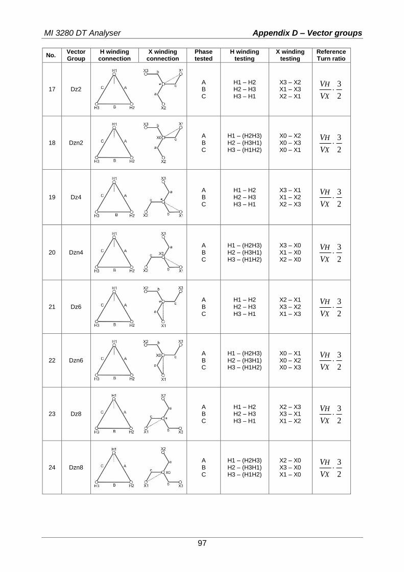
MI 3280 DT Analyser Appendix D – Vector groups
97
No. Vector Group
H winding connection
X winding connection
Phase tested
H winding testing
X winding testing
Reference Turn ratio
17 Dz2
A B C
H1 – H2 H2 – H3 H3 – H1
X3 – X2 X1 – X3 X2 – X1 2
3
X
H
V
V
18 Dzn2
A B C
H1 – (H2H3) H2 – (H3H1) H3 – (H1H2)
X0 – X2 X0 – X3 X0 – X1 2
3
X
H
V
V
19 Dz4
A B C
H1 – H2 H2 – H3 H3 – H1
X3 – X1 X1 – X2 X2 – X3 2
3
X
H
V
V
20 Dzn4
A B C
H1 – (H2H3) H2 – (H3H1) H3 – (H1H2)
X3 – X0 X1 – X0 X2 – X0 2
3
X
H
V
V
21 Dz6
A B C
H1 – H2 H2 – H3 H3 – H1
X2 – X1 X3 – X2 X1 – X3 2
3
X
H
V
V
22 Dzn6
A B C
H1 – (H2H3) H2 – (H3H1) H3 – (H1H2)
X0 – X1 X0 – X2 X0 – X3 2
3
X
H
V
V
23 Dz8
A B C
H1 – H2 H2 – H3 H3 – H1
X2 – X3 X3 – X1 X1 – X2 2
3
X
H
V
V
24 Dzn8
A B C
H1 – (H2H3) H2 – (H3H1) H3 – (H1H2)
X2 – X0 X3 – X0 X1 – X0 2
3
X
H
V
V

MI 3280 DT Analyser Appendix D – Vector groups
98
No. Vector Group
H winding connection
X winding connection
Phase tested
H winding testing
X winding testing
Reference Turn ratio
25 Dz10
A B C
H1 – H2 H2 – H3 H3 – H1
X1 – X3 X2 – X1 X3 – X2 2
3
X
H
V
V
26 Dzn10
A B C
H1 – (H2H3) H2 – (H3H1) H3 – (H1H2)
X0 – X3 X0 – X1 X0 – X2 2
3
X
H
V
V
27 Yy0
A B C
H1 – (H2H3) H2 – (H3H1) H3 – (H1H2)
X1 – (X2X3) X2 – (X3X1) X3 – (X1X2) X
H
V
V
28 Yyn0
A B C
H1 – (H2H3) H2 – (H3H1) H3 – (H1H2)
X1 – X0 X2 – X0 X3 – X0 X
H
V
V
29 YNy0
A B C
H1 – H0 H2 – H0 H3 – H0
X1 – (X2X3) X2 – (X3X1) X3 – (X1X2) X
H
V
V
30 YNyn0
A B C
H1 – H0 H2 – H0 H3 – H0
X1 – X0 X2 – X0 X3 – X0 X
H
V
V
31 Yy6
A B C
H1 – (H2H3) H2 – (H3H1) H3 – (H1H2)
(X2X3) – X1 (X3X1) – X2 (X1X2) – X3 X
H
V
V
32 Yyn6
A B C
H1 – (H2H3) H2 – (H3H1) H3 – (H1H2)
X0 – X1 X0 – X2 X0 – X3 X
H
V
V

MI 3280 DT Analyser Appendix D – Vector groups
99
No. Vector Group
H winding connection
X winding connection
Phase tested
H winding testing
X winding testing
Reference Turn ratio
33 YNy6
A B C
H1 – H0 H2 – H0 H3 – H0
(X2X3) – X1 (X3X1) – X2 (X1X2) – X3 X
H
V
V
34 YNyn6
A B C
H1 – H0 H2 – H0 H3 – H0
X0 – X1 X0 – X2 X0 – X3 X
H
V
V
35 Yd1
A B C
H1 – (H2H3) H2 – (H3H1) H3 – (H1H2)
X1 – X2 X2 – X3 X3 – X1 3X
H
V
V
36 YNd1
A B C
H1 – H0 H2 – H0 H3 – H0
X1 – X2 X2 – X3 X3 – X1 3X
H
V
V
37 Yd5
A B C
H1 – (H2H3) H2 – (H3H1) H3 – (H1H2)
X3 – X1 X1 – X2 X2 – X3 3X
H
V
V
38 YNd5
A B C
H1 – H0 H2 – H0 H3 – H0
X3 – X1 X1 – X2 X2 – X3 3X
H
V
V
39 Yd7
A B C
H1 – (H2H3) H2 – (H3H1) H3 – (H1H2)
X2 – X1 X3 – X2 X1 – X3 3X
H
V
V
40 YNd7
A B C
H1 – H0 H2 – H0 H3 – H0
X2 – X1 X3 – X2 X1 – X3 3X
H
V
V

MI 3280 DT Analyser Appendix D – Vector groups
100
No. Vector Group
H winding connection
X winding connection
Phase tested
H winding testing
X winding testing
Reference Turn ratio
41 Yd11
A B C
H1 – (H2H3) H2 – (H3H1) H3 – (H1H2)
X1 – X3 X2 – X1 X3 – X2 3X
H
V
V
42 YNd11
A B C
H1 – H0 H2 – H0 H3 – H0
X1 – X3 X2 – X1 X3 – X2 3X
H
V
V
43 Yz1
A B C
H1 – (H2H3) H2 – (H3H1) H3 – (H1H2)
X1 – X2 X2 – X3 X3 – X1 2
3
X
H
V
V
44 Yzn1
A B C
H1 – (H2H3) H2 – (H3H1) H3 – (H1H2)
X1 – X0 X2 – X0 X3 – X0 2
3
X
H
V
V
45 Yz5
A B C
H1 – (H2H3) H2 – (H3H1) H3 – (H1H2)
X3 – X1 X1 – X2 X2 – X3 2
3
X
H
V
V
46 Yzn5
A B C
H1 – (H2H3) H2 – (H3H1) H3 – (H1H2)
X3 – X0 X1 – X0 X2 – X0 2
3
X
H
V
V
47 Yz7
A B C
H1 – (H2H3) H2 – (H3H1) H3 – (H1H2)
X2 – X1 X3 – X2 X1 – X3 2
3
X
H
V
V
48 Yzn7
A B C
H1 – (H2H3) H2 – (H3H1) H3 – (H1H2)
X0 – X1 X0 – X2 X0 – X3 2
3
X
H
V
V

MI 3280 DT Analyser Appendix D – Vector groups
101
No. Vector Group
H winding connection
X winding connection
Phase tested
H winding testing
X winding testing
Reference Turn ratio
49 Yz11
A B C
H1 – (H2H3) H2 – (H3H1) H3 – (H1H2)
X1 – X3 X2 – X1 X3 – X2 2
3
X
H
V
V
50 Yzn11
A B C
H1 – (H2H3) H2 – (H3H1) H3 – (H1H2)
X0 – X3 X0 – X1 X0 – X2 2
3
X
H
V
V

MI 3280 DT Analyser Appendix E – Detailed wiring diagram of specific meas…
102
Appendix E – Detailed wiring diagram of specific measurements
Detailed wiring diagram of specific measurements:
Figure E.1: Turn ratio testing (r) of single-phase voltage or power transformer (VT/PT)
Figure E.2: Turn ratio testing (r) of single-phase current transformer (CT)

MI 3280 DT Analyser Appendix E – Detailed wiring diagram of specific meas…
103
Figure E.3: Turn ratio testing (rA, rB, rC) of three-phase transformer
Figure E.4: Windings resistance testing (R) on H and/or X side of single-phase transformer

MI 3280 DT Analyser Appendix E – Detailed wiring diagram of specific meas…
104
Figure E.5: Windings resistance testing (RA, RB, RC) on H and/or X side of three-phase transformer

MI 3280 DT Analyser Appendix F – Testing the instrument precision
105
Appendix F – Testing the instrument precision Connect H0 | H1 and X0 | X1 to appropriate MI 3280 DT Analyser terminal. Connect reference
resistor of 1 k (1 W) to H and X leads as shown in Figure F.1. Choose single-phase turn ratio measurement (r), select transformer type as current transformer (CT), select Vex as 10V and start the measurement. You should read r between 0,9978 and 1,0022 if MI 3280 is operating inside its tolerances. Resistor is crucial for fulfilling the criteria for the connection pretest.
Figure F.1: Testing the instrument precision

MI 3280 DT Analyser Appendix G – Programming of Auto Sequence®…
106
Appendix G – Programming of Auto Sequence® on Metrel ES Manager
The Auto test editor is a part of the Metrel ES Manager software. In Auto test editor an Auto Sequence can be pre-programmed and organized in groups, before uploaded to the instrument.
I. Auto test editor workspace
To enter Auto test editor’s workspace, select in Home Tab of Metrel ES Manager PC
SW. Auto test editor workspace is divided in four main areas. On the left side ,structure of
selected group of Auto Sequence is displayed. In the middle part of the workspace , the elements of the selected Auto Sequence are shown. On the right side, list of available single
tests and list of flow commands are shown.
Figure G.1: Auto Test editor workspace
An Auto test sequence begins with Name, Description and Image, followed by the first step (Header), one or more measuring steps and ends with the last step (Result). By inserting
appropriate Single tests and Flow commands and setting their parameters, arbitrary Auto test sequences can be created.

MI 3280 DT Analyser Appendix G – Programming of Auto Sequence®…
107
Figure G.2: Example of an Auto sequence header
Figure G.3: Example of a measurement step
Figure G.4: Example of an Auto sequence result part
II. Managing groups of Auto Sequence
The Auto Sequence can be divided into different user defined groups of Auto Sequences. Each group of Auto Sequences is stored in a file. More files can be opened simultaneously in Auto test editor. Within Group of Auto Sequence, tree structure can be organized, with folders / subfolders containing Auto Sequences. The three structure of currently active Group of Auto Sequence is displayed on the left side of the Auto test editor workspace, see Figure G.5..
Figure G.5: Group of Auto Sequence tree organization
Operation options on Group of Auto Sequence are available from menu bar at the top of Auto test editor workspace. File operation options:
Opens a file (Group of Auto Sequences).
Saves / Saves as the opened Group of Auto Sequence to a file.
Creates a new file (Group of Auto Sequences).
Closes the file (Group of Auto Sequences).

MI 3280 DT Analyser Appendix G – Programming of Auto Sequence®…
108
Group of Auto Sequence operation options (also available by right clicking on Folder or Auto Sequence):
Adds a new folder / subfolder to the group
Adds a new Auto Sequence to the group.
Deletes: the selected Auto Sequence the selected folder with all subfolders and Auto Sequence
Right click on the selected Auto test or Folder opens menu with additional possibilities:
Auto test: Edit Name, Description and Image (see Figure G.6). Folder: Edit folder name
Auto test: Copy to clipboard Folder: Copy to clipboard including subfolders and Auto Sequence
Auto test: Cut it to clipboard Folder: Cut it to clipboard together with all subfolders and all Auto Sequence
Auto test: Paste it to selected location Folder: Paste it to selected location
Double click on the object name allows name edit:
DOUBLE CLICK
Auto test name: Edit Auto Sequence name
Folder name: Edit folder name
Drag and drop of the selected Auto test or Folder / Subfolder moves it to a new location:
DRAG & DROP
“Drag and drop” functionality is equivalent to “cut” and “paste” in a single move.
move to folder
insert
Figure G.6: Editing the Auto sequence header

MI 3280 DT Analyser Appendix G – Programming of Auto Sequence®…
109
III. Elements of an Auto sequence
Auto sequence steps There are three kinds of Auto sequence steps.
Header
The Header step is empty by default. Flow commands can be added to the Header step.
Measurement step The Measurement step contains a Single test and the Operation after end of test flow command by default. Other Flow commands can also be added to the Measurement step.
Result
The Result step contains the Result screen flow command by default. Other Flow commands can also be added to the Result step. Single tests
Single tests are the same as in Metrel ES Manager Measurement menu. Limits and parameters of the measurements can be set. Results and sub-results can’t be set. Flow commands
Flow commands are used to control the flow of measurements. Refer to chapter Description of flow commands for more information. Number of measurement steps
Often the same measurement step has to be performed on multiple points on the device under test. It is possible to set how many times a Measurement step will be repeated. All carried out individual Single test results are stored in the Auto test result as if they were programmed as independent measuring steps.
IV. Creating / modifying an Auto sequence
If creating a new Auto sequence from scratch, the first step (Header) and the last step (Result) are offered by default. Measurement steps are inserted by the user. Options:
Adding a measurement step By double clicking on a Single test a new measurement step will appear as the last of measurement steps. It can also be dragged and dropped on the appropriate position in the Auto sequence.
Adding flow commands Selected flow command can be dragged from the list of Flow commands and dropped on the appropriate place in any Auto sequence step.
Changing position of flow command inside one step By a click on an element and use of , keys.
Viewing / changing parameters of flow commands or single tests.
By a double click on the element.
Setting number of measurement steps
By setting a number from 1 to 20 in the field.
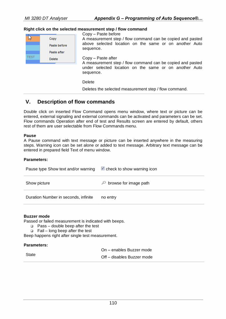
MI 3280 DT Analyser Appendix G – Programming of Auto Sequence®…
110
Right click on the selected measurement step / flow command
Copy – Paste before A measurement step / flow command can be copied and pasted above selected location on the same or on another Auto sequence. Copy – Paste after A measurement step / flow command can be copied and pasted under selected location on the same or on another Auto sequence. Delete
Deletes the selected measurement step / flow command.
V. Description of flow commands
Double click on inserted Flow Command opens menu window, where text or picture can be entered, external signaling and external commands can be activated and parameters can be set. Flow commands Operation after end of test and Results screen are entered by default, others rest of them are user selectable from Flow Commands menu. Pause A Pause command with text message or picture can be inserted anywhere in the measuring steps. Warning icon can be set alone or added to text message. Arbitrary text message can be entered in prepared field Text of menu window. Parameters:
Pause type Show text and/or warning check to show warning icon
Show picture browse for image path
Duration Number in seconds, infinite no entry
Buzzer mode Passed or failed measurement is indicated with beeps.
Pass – double beep after the test Fail – long beep after the test
Beep happens right after single test measurement. Parameters:
State On – enables Buzzer mode
Off – disables Buzzer mode

MI 3280 DT Analyser Appendix G – Programming of Auto Sequence®…
111
Operation after end of test This flow command controls the proceeding of the Auto sequence in regard to the measurement results. Parameters:
Operation after end of test – pass – fail – no status
The operation can be individually set for the case the measurement passed, failed or ended without a status.
Manual – The test sequence stops and waits for
apropriate command (Enter key) to proceed.
Auto – The test sequence automatically proceeds.