mht+y ,oa fo|qr jsy batuks dsa bksl jksym efyviy & f?klko … · · 2015-07-15... qr jsy...
TRANSCRIPT
Hkkjr ljdkj, jsy eU=zky;
GOVERNMENT OF INDIA MINISTRY OF RAILWAYS
Mht+y ,oa fo|qr jsy batuksa ds Bksl jksYM efYViy & f?klko okys ifg;ksa ds fy, Hkkjrh; jsy ekud fof"’kB
lHkh xstksa ds fy, ykxw
INDIAN RAILWAY STANDARD SPECIFICATION FOR SOLID ROLLED MULTIPLE WEAR WHEELS
for Diesel and Electric locomotives, carriages (including EMU/DMU/MEMU and self propelled vehicles) and wagons
(Applicable to all Gauges)
MP. No. …….. July 2015
vuqla/kku vfHkdYi vkSj ekud laxBu y[kuÅ&226 011
RESEARCH DESIGNS & STANDARDS ORGANISATION LUCKNOW - 226 011
Cost (Rs).………
R.D.S.O

Hkkjr ljdkj, jsy eU=zky;
GOVERNMENT OF INDIA MINISTRY OF RAILWAYS
Bksl jksYM efYViy & f?klko okys ifg;ksa ds fy, Hkkjrh; jsy ekud fof"’kB
lHkh xstksa ds fy, ykxw
INDIAN RAILWAY STANDARD SPECIFICATION FOR SOLID ROLLED MULTIPLE WEAR WHEELS
for Diesel and Electric locomotives, carriages (including EMU/DMU/MEMU and self propelled vehicles) and wagons
(Applicable to all Gauges)
MP. No. --------------
vuqla/kku vfHkdYi vkSj ekud laxBu y[kuÅ&226 011
RESEARCH DESIGNS & STANDARDS ORGANISATION LUCKNOW - 226 011
Cost (Rs).………
Prepared By
Checked By
Approved By
R.D.S.O R.D.S.O
Indian Railway Standard Specification for Solid Rolled Multiple Wear Wheels for Diesel and Electric locomotives, carriages (including EMU/DMU/MEMU and self propelled vehicles) and wagons
Motive Power Directorate, RDSO, Lucknow Serial No. xxxxx
FOREWORD
International Standards i.e AAR, EN, ISO Standards of forged wheels are common standards irrespective of type of rolling stocks i.e. for locomotive, carriage and wagons. In line with that, Railway Board, vide their letter no.2012/M(L)/466/2/2701/Vol.III dated 25.06.2015, advised RDSO to develop a common specification for forged wheels of Locomotive, Carriage and Wagons. Till now forged wheels are procured by Railway Board through Global Tenders from separate specifications of locomotive and carriage wheels i.e. IRS: R-34 & R-19 (Part-II). The common specification is developed combining requirements of both specifications i.e. R34 and R19 (Part-II). Specific mention of relevant requirements are also categorized as R34 and R19 in the specification where requirements are not similar.
Indian Railway Standard Specification for Solid Rolled Multiple Wear Wheels for Diesel and Electric locomotives, carriages (including EMU/DMU/MEMU and self propelled vehicles) and wagons
Motive Power Directorate, RDSO, Lucknow MP No. xxxxx
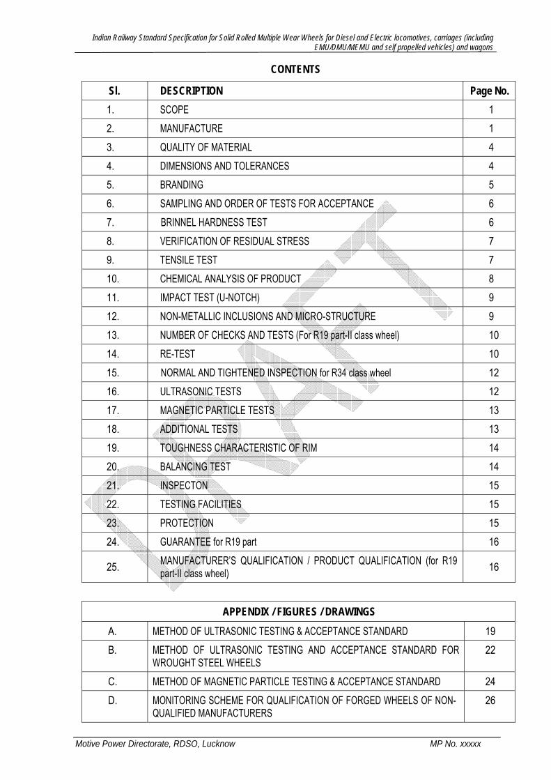
CONTENTS
Sl. DESCRIPTION Page No. 1. SCOPE 1 2. MANUFACTURE 1 3. QUALITY OF MATERIAL 4 4. DIMENSIONS AND TOLERANCES 4 5. BRANDING 5 6. SAMPLING AND ORDER OF TESTS FOR ACCEPTANCE 6 7. BRINNEL HARDNESS TEST 6 8. VERIFICATION OF RESIDUAL STRESS 7 9. TENSILE TEST 7 10. CHEMICAL ANALYSIS OF PRODUCT 8 11. IMPACT TEST (U-NOTCH) 9 12. NON-METALLIC INCLUSIONS AND MICRO-STRUCTURE 9 13. NUMBER OF CHECKS AND TESTS (For R19 part-II class wheel) 10 14. RE-TEST 10 15. NORMAL AND TIGHTENED INSPECTION for R34 class wheel 12 16. ULTRASONIC TESTS 12 17. MAGNETIC PARTICLE TESTS 13 18. ADDITIONAL TESTS 13 19. TOUGHNESS CHARACTERISTIC OF RIM 14 20. BALANCING TEST 14 21. INSPECTON 15 22. TESTING FACILITIES 15 23. PROTECTION 15 24. GUARANTEE for R19 part 16
25. MANUFACTURER’S QUALIFICATION / PRODUCT QUALIFICATION (for R19 part-II class wheel) 16
APPENDIX / FIGURES / DRAWINGS A. METHOD OF ULTRASONIC TESTING & ACCEPTANCE STANDARD 19 B. METHOD OF ULTRASONIC TESTING AND ACCEPTANCE STANDARD FOR
WROUGHT STEEL WHEELS 22
C. METHOD OF MAGNETIC PARTICLE TESTING & ACCEPTANCE STANDARD 24 D. MONITORING SCHEME FOR QUALIFICATION OF FORGED WHEELS OF NON-
QUALIFIED MANUFACTURERS 26
Indian Railway Standard Specification for Solid Rolled Multiple Wear Wheels for Diesel and Electric locomotives, carriages (including EMU/DMU/MEMU and self propelled vehicles) and wagons
Motive Power Directorate, RDSO, Lucknow MP No. xxxxx
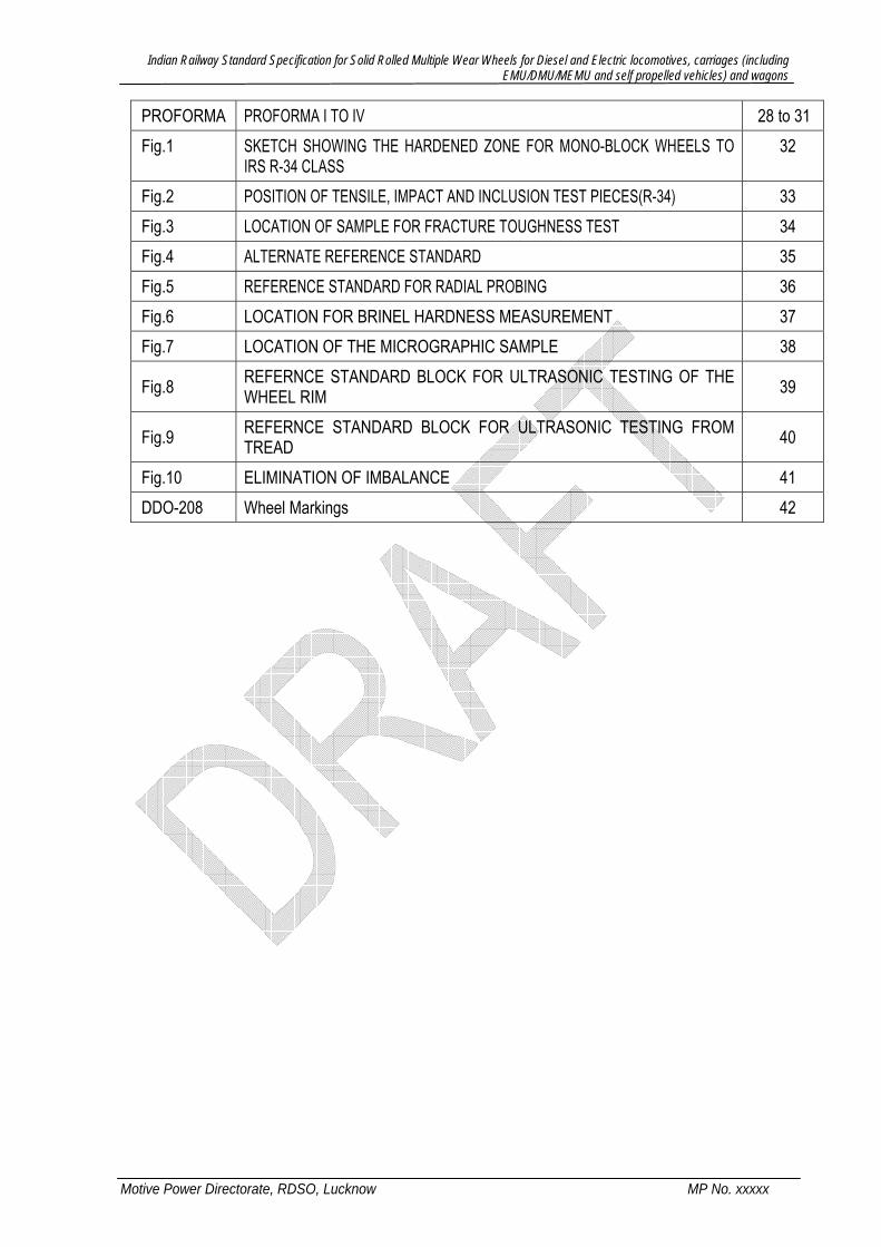
PROFORMA PROFORMA I TO IV 28 to 31 Fig.1 SKETCH SHOWING THE HARDENED ZONE FOR MONO-BLOCK WHEELS TO
IRS R-34 CLASS 32
Fig.2 POSITION OF TENSILE, IMPACT AND INCLUSION TEST PIECES(R-34) 33 Fig.3 LOCATION OF SAMPLE FOR FRACTURE TOUGHNESS TEST 34 Fig.4 ALTERNATE REFERENCE STANDARD 35 Fig.5 REFERENCE STANDARD FOR RADIAL PROBING 36 Fig.6 LOCATION FOR BRINEL HARDNESS MEASUREMENT 37 Fig.7 LOCATION OF THE MICROGRAPHIC SAMPLE 38
Fig.8 REFERNCE STANDARD BLOCK FOR ULTRASONIC TESTING OF THE WHEEL RIM 39
Fig.9 REFERNCE STANDARD BLOCK FOR ULTRASONIC TESTING FROM TREAD 40
Fig.10 ELIMINATION OF IMBALANCE 41 DDO-208 Wheel Markings 42
Indian Railway Standard Specification for Solid Rolled Multiple Wear Wheels for Diesel and Electric locomotives, carriages (including EMU/DMU/MEMU and self propelled vehicles) and wagons
Motive Power Directorate, RDSO, Lucknow MP No. xxxxx Page 1 of 42
INDIAN RAILWAY STANDARD SPECIFICATION FOR SOLID ROLLED MULTIPLE WEAR WHEELS
(Applicable to all Gauges) 1. SCOPE
1.1 This standard covers the requirements of heat treated solid forged and rolled multiple-wear wheels for Diesel and Electric locomotives, carriages (including EMU/DMU/MEMU and self propelled vehicles) and wagons of all gauges. The specific requirements of locomotive wheel are covered under Class R34. Similarly, specific requirements of carriages (including EMU/DMU/MEMU and self propelled vehicles) and wagons application is covered under Class R19 part II. The Class R19 part II also incorporates a procedure for qualification of wheels from non qualified suppliers, which in turn is based on similar provisions of EN 13262.
1.2 Any special requirements given in the relevant drawings will override this specification.
2. MANUFACTURE 2.1 Process of steel manufacture The wheel shall be manufactured from steel made by Electric or Basic Oxygen process.
The steel should be vacuum degassed and shall be of killed quality. Manufacturer shall furnish full details of steel making process and take prior approval from the purchaser for the use of any other equivalent process for manufacture of steel.
2.1.1 Hydrogen Content The steel shall be vacuum degassed and hydrogen content in liquid steel shall not be more than 2.5 PPM. Hydrogen analysis shall be done as given in Para 2.1.2 & 2.1.3.
2.1.2 Sampling for Hydrogen Analysis The sample of liquid steel shall be taken from ladle by plunging the sampler 300 mm below the molten metal-slag interface. The sample shall be held 2-3 seconds and then quenched in cold water so that the sample temperature falls below 150°C within 5 seconds. The sample shall be removed from cold water and immediately packed in dry ice or liquid Nitrogen. The sample shall be analyzed within 48 hours and till the time of analysis, the sample shall continuously be fully covered by dry ice / liquid Nitrogen. Sampling shall be done by 6 mm diameter tube of Pyrex glass or ceramic which does not react with steel. General wall thickness of the tube shall be 1.5 mm and at the fill end 0.5 mm approx. The tube should be under vacuum of 10-3 bar (0.76 mm of Hg). Any other method of sampling shall have a prior approval of the purchaser.
2.1.3 Hydrogen Analysis The analysis of sample shall be done by Inert Gas Fusion technique in which sample is fused at around 1900°C in induction heating crucible. A Nitrogen carrier gas transports the released Hydrogen to a thermal conductivity cell. The amplified and integrated output of the cell is to be calibrated for Hydrogen in PPM. A Leco-RH-3 Hydrogen analyzer or similar precision equipment may be used for Hydrogen determination. Hydris system may be used for online / instantaneous measurement of Hydrogen content in liquid steel. Any other method for Hydrogen Analysis shall have a prior approval of the purchaser.
2.1.4 The Nitrogen content in the steel shall not exceed 0.007 percent.
Indian Railway Standard Specification for Solid Rolled Multiple Wear Wheels for Diesel and Electric locomotives, carriages (including EMU/DMU/MEMU and self propelled vehicles) and wagons
Motive Power Directorate, RDSO, Lucknow MP No. xxxxx Page 2 of 42
2.2 Chemical composition 2.2.1 Ladle Analysis: The ladle analysis of steel, when carried out by the method specified in
relevant parts of IS: 2281 (latest versions) or any other established instrumental / chemical method, shall be as follows:
Element R34 R19 part II
Carbon 0.57 to 0.67 or as specifically mentioned in the drawing 0.52 max
Manganese 0.6 to 0.85 0.6 to 0.80 Silicon 0.15 min 0.15 to 0.4 Sulphur 0.03 max 0.03 max Phosphorus 0.03 max 0.03 max Mo 0.06 max 0.06 max Vanadium 0.10 max 0.10 max Chromium 0.25 max Combined 0.50 %
max 0.25 max
Copper 0.28 max 0.2 max Nickel 0.25 max 0.25 max
Aluminum 0.02 * (preferable)
* Aluminum upto 0.04% (max.) is permitted.
----------
Cr+Ni+Mo=0.5 max (combined)
In case of dispute, the procedure given in IS: 2281 and its relevant parts shall be the reference method. However, where the method is not given in IS: 228 and its relevant parts, the reference method shall be as agreed between the purchaser and the manufacturer.
2.2.2 Product Analysis: The product analysis is to be carried out as laid down in Clause 10. The permissible variation from the limits specified in Clause 2.2.1 shall be as follows: Elements Variation Percent for
R 34 Elements Variation Percent
for R19 part II Carbon + 0.03 / - 0.02 Carbon + 0.03 / - 0.02 Manganese ± 0.03 Manganese & Silicon ± 0.03 Silicon - 0.03 Phosphorus & Sulphur + 0.005/-0.000
Phosphorus + 0.005 Chromium & Nickel + 0.05/-0.00 Sulphur + 0.005 Copper & Vanadium + 0.02/-0.00 Chromium,Nickel & Copper
+ 0.05
Molybdenum& Vanadium
+ 0.02
Aluminum + 0.002 (Aluminium content in product analysis upto 0.04% (max.) is permissible including this variation )
1 Method for chemical analysis of steel
Indian Railway Standard Specification for Solid Rolled Multiple Wear Wheels for Diesel and Electric locomotives, carriages (including EMU/DMU/MEMU and self propelled vehicles) and wagons
Motive Power Directorate, RDSO, Lucknow MP No. xxxxx Page 3 of 42
2.3 Manufacturing of wheel 2.3.1 The wheels shall be manufactured by forging and rolling process from cropped ingots, in
such a manner that the central axis of the ingot or the bloom coincides with the axis of the wheel. Sufficient discard shall be made from both ends of each ingot to ensure freedom from piping and undesirable segregations. Each ingot shall be of suitable section and length to produce two or more wheel blanks after top & bottom discards have been made to eliminate the defective portion completely. Suitable precautions shall be taken during hot working to ensure that material is not damaged by over heating or by grain growth due to prolonged exposure at high temperature. The temperature of the product should not exceed 1260 degree C and working should terminate between 850 and 1000 degree C.
2.3.2 The wheels can also be manufactured from cheeses of steel blooms of suitable section, length and weight manufactured by the continuous casting method in such a manner that the central axis of the ingot or the bloom coincides with the axis of the wheel. The steel shall be refined in the ladle furnace and vacuum de-gassed before using continuous casting process. Suitable shrouding arrangements from the ladle to tundish and from tundish to mould shall be made. The continuous casting machine shall have the facility of electromagnetic stirring.
2.3.3 The manufacturer shall furnish full details of the steel making process including ladle refining and vacuum degassing and take prior approval from the purchaser for the use of the above methods. The minimum cross section of the cropped ingot or continuous cast bloom shall be such that a minimum reduction ratio of 4:1 is obtained. That is, the original height of cropped ingot piece should be at least 4 times the height of upset blank at the completion of up-setting.
2.4 Cooling 2.4.1 During manufacture, necessary care shall be exercised in regulation of temperature to obtain
the best physical properties, expected from the chemical composition & mechanical work and to achieve the desired microstructure.
2.4.2 After the last hot forming operation i.e. dishing and coning, all wheels shall be slowly cooled, protected from draft of air or handled in such a manner so as to prevent injury by rapid cooling below the critical range.
2.4.3 Optimised cooling regime should form part of a documented Quality Assurance Plan (QAP).
2.5 Heat treatment The heat treatment shall consist treatment of only rim by way of rim quenching and subsequent wheel tempering. While employing water spraying during rim quenching, care should be taken to prevent access of cooling medium to the web and as to prevent the formation of cracks. .
2.5.1 Rim Quenching treatment for R 34 class wheel: This treatment entails heating the wheel for a sufficient time to bring it uniformly to a temperature of at least 825°C and then hardening the rim with jets of water under pressure the wheel must rotate during the rim quenching process followed by wheel tempering to a temperature of 480ºC to 520°C. The wheel is then left to cool in still air preferably in a covered cooling pit or under cover. However, this heat treatment schedule is indicative only meant for guidance. The firm shall determine their heat treatment schedule on the basis of chemical composition of the metal and their laid down heat treatment process approval plan. The firm shall clearly bring out their heat treatment schedule in the QAP.
2.5.2 Rim Quenching treatment for R 19 part II class wheel: Rim quenching and tempering shall be understood to mean heating the wheel for a sufficient time to bring it uniformly to a temperature exceeding the transformation temperature of the steel within 500C, then
Indian Railway Standard Specification for Solid Rolled Multiple Wear Wheels for Diesel and Electric locomotives, carriages (including EMU/DMU/MEMU and self propelled vehicles) and wagons
Motive Power Directorate, RDSO, Lucknow MP No. xxxxx Page 4 of 42
hardening the rim with a jet of water under pressure, followed by tempering at Minimum temperature of 5000C. The wheel is then left to cool in still air/draught free area preferably in a covered cooling pit or under cover. The wheel can also be cooled in “retarded-cooling chambers of conveyer type.” The heat treatment shall not modify the hardness values measured at point –A (Fig. 6)
3. QUALITY OF MATERIAL The wheel shall be sound throughout, free from cracks, surface flaws, laminations, inclusions, laps, hydrogen flakes and all other harmful defects.
4. DIMENSIONS AND TOLERANCES
4.1 The wheels shall be accurately machined to the dimensions and tolerances shown in the relevant drawings. When maximum weight of the finished wheel is shown in the drawing, the tolerances indicated should be worked to close limits so as not to exceed the specified weight. Any wheel not cleaning up perfectly true in the lathe shall be rejected.
4.2 The radii at junction of the web with rim and web with hub on both sides shall be machined without leaving black spots so as to blend smoothly with the web, as shown in the relevant drawings. Any hole indicated in the drawing shall also be machined and flame cutting shall not be resorted to.
4.3 For R34 class wheel, permissible variation in the dimensions where tolerances are not given in the individual drawing(s) shall be as follows:
4.3.1 Thickness of rim: The radial thickness of the rim shall not vary more than 3mm around the wheel circumference.
4.3.2 Plane of back / inside face: When wheels are gauged with a straight edge applied to back face of the rim, no point on back face of rim shall be more than 1mm from the straight edge.
4.3.3 Hub wall thickness: The thickness of the hub wall measured at any two points, equidistant from the face of the hub, shall not vary by more than 2 mm.
4.3.4 Rotundity: Tread when gauged with a ring gauge, must not have opening over 0.5mm between the tread and the gauge at any point.
4.3.5 Diameter of bore: The diameter of rough finished bore shall not vary by more than 2mm from the dimension shown in the relevant drawing.
4.3.6 Eccentricity: Eccentricity between the rough bore and tread, measured in the plane of taping line shall not exceed 3 mm.
4.3.7 The difference between the minimum and maximum thickness of web at any given radius shall not be more than 1.5 mm.
4.4 For R19 Part-II Class Wheel 4.4.1 WEB THICKNESS: In case tolerances are not given in the drawing, the web shall be of
uniform thickness and shall not vary more than 5.0 mm over the specified dimension. In any one wheel, the difference between the minimum and maximum thickness of web at any given radius shall not be more than 1.5 mm.
4.4.2 MACHINING AND ELIMINATION OF IMBALANCE: Machining operation shall be chosen so that the wheels comply with the requirements for both surface finish and tolerances specified by the purchaser. Elimination of imbalance shall be obtained by eccentric machining of the fillet between the web and the rim, on the flange side as shown in Fig.10. The thickness of
Indian Railway Standard Specification for Solid Rolled Multiple Wear Wheels for Diesel and Electric locomotives, carriages (including EMU/DMU/MEMU and self propelled vehicles) and wagons
Motive Power Directorate, RDSO, Lucknow MP No. xxxxx Page 5 of 42
the metal removed shall not exceed 4 mm and the resultant surface shall be carefully blended into adjacent material. In no case shall it be permitted to add additional mass. Drilling of holes for correction of imbalance is prohibited. The sprag holes or any other holes as indicated in the drawing will be made by machining and not by flame cutting.
5. BRANDING 5.1 For R34 class wheel: Each wheel shall be legibly stamped on the outside face of hub as
indicated in DDO-208 (latest alteration).Care shall be taken to ensure that the impressions do not have sharp corners/edges and the entire preparation is suitably rounded to remove sharp corners.
5.1.1 Manufacturer shall maintain and preserve the record co-relating every individual wheel with the cast number, drawing number of the wheel and heat treatment given, and produce the same on demand by the purchaser /inspecting officer.
5.2 For R19 part-II class wheel: 5.2.1 Following particulars as shown on the RDSO Drg. Sk.-92114 shall be hot stamped on the
outer face of rim of each wheel before machining. 1. Maker’s code name (in 3 digits, with purchaser’s prior approval) 2. Year of manufacture (in 2 digits i.e. the year 2006 shall be indicated as 06). 3. Individual serial number (in 5 digits). 4. Batch Number 5. Inspector’s approval stamp 6. ‘UT’ for ultrasonic testing
5.2.2 For LHB wheels to RCF’s drg. No. LW02103, stamping should be done on outer face of the hub. Particulars of S.No. 1 to 4 shall also be stamped on outer hub fillet at location marked as ‘X’, in the RDSO drawing No. 92114, for easy identification in fitted condition in coach. The wheel shall be stamped such that height of the letters is 10 mm minimum. The depth of letters with hot stamping shall be between 2 mm to 3 mm.
5.2.3 For wheels, which are fully machined after heat treatment, the hot stamped particulars are likely to be removed during machining. For such wheels, the particulars hot stamped should be transferred by cold stamping. However, care should be taken that the impression does not have sharp corners/edges and the entire preparation is suitably rounded to remove the sharp corners. The depth of cold stamping should be in between 0.15 mm to 0.5 mm. Stamping by localized heating is prohibited.
5.2.4 Manufacturer should ensure complete traceability of their wheels throughout the life cycle of the wheel.
5.2.5 The position of residual imbalance, if desired by the purchaser, shall be indicated by a paint mark consisting of a radial stripe about 15mm wide. The values of imbalance shall be indicated below the end of the stripe according to the following code: - • E1 for a residual imbalance of < 50 gm-m. • E2 for a residual imbalance of < 75 gm-m. • E3 for a residual imbalance of < 125 gm-m.
5.2.6 Manufacturer shall maintain and preserve the record co-relating every individual wheel with the cast number, the contract number, the drawing number of the wheel and heat treatment given and produce the same on demand by the purchaser/Inspecting officer. The details regarding the contract number and drawing number of every wheel shall be furnished to the consignee.
Indian Railway Standard Specification for Solid Rolled Multiple Wear Wheels for Diesel and Electric locomotives, carriages (including EMU/DMU/MEMU and self propelled vehicles) and wagons
Motive Power Directorate, RDSO, Lucknow MP No. xxxxx Page 6 of 42
6. SAMPLING AND ORDER OF TESTS FOR ACCEPTANCE 6.1 For R34 class wheel 100% wheels shall be checked for appearance, dimensions, branding
particulars, hardness at outside face of the rim, ultrasonic testing and magnetic particle test. For other tests i.e. destructive tests, following provisions shall be applicable.
6.1.1 Lot Size Lot size will be 250 or less. All the wheels of a lot shall be from the same heat and heat treatment batch.
6.1.2 Sample for destructive tests Random sampling shall be followed with the sample size as given below:
Sample size will be 1. The selected wheels shall pass the outside hardness test as specified in Clause 7.1.1 Wheels selected for destructive testing may be in un-machined or machined condition at the discretion of the manufacturer. If the selected wheels are in un-machined condition, the surface should be prepared by grinding or other suitable method for hardness measurement.
6.1.3 Order of the tests Wheel of the above sample shall be subjected to the tests stipulated in Clause 7.1.1 on compliance to the clause 7.1.1, the same wheel shall be subjected to tests stipulated in clause 8 followed by tests mentioned in clauses 7.1.3, 9.1, 10.1, 11.1 and 12.1 Preferably, the destructive tests should be conducted in un-machined condition of the lot, after duly preparing the surface of the sample wheels for hardness test as per Clause 7.1.1. This is to avoid any likely damage to the surface if reheat treatment is required. For R19 part-II class wheel:
SELECTION OF TEST PIECES The number of wheels per batch to be subjected to the checks and tests shall be in accordance with Table-3. Test pieces shall be selected at random by the inspector and shall be stamped for identification. For this purpose, each batch shall comprise of wheels from the same cast and having undergone the same heat treatment. However, for chemical analysis and macroscopic examinations, the batch shall comprise of wheels from the same cast
7. BRINELL HARDNESS TEST 7.1 For R34 class wheel: Brinell Hardness test shall be conducted with 10 mm diameter ball &
29.42 kN force (3000 kg load) combination as per IS:15002 (latest version). Any other method shall require purchaser’s or his inspecting officer's prior approval.
7.1.1 Hardness on outside face of the rim: This test shall be conducted on all wheels after machining to the size as per the drawing. The hardness of the rim when measured on its outside face, with the edge of impression not less than 12 mm from the chamfer joining the face and tread shall show Brinell Hardness number 300 to 341 and the hardening effect shall be to a depth of about 30 mm from the tread as measured on the out side face of the rim. The hardness number at a depth of 30mm from the tread shall not be less than 300BHN.
7.1.2 Uniformity of hardness of batch: The extreme hardness values of the rim of wheels from the same batch shall not vary by more than 30 BHN.
7.1.3 Hardness Test on Cut Section: Hardness survey shall indicate a smooth transition from the radius face to the tread face. Any decarburised metal shall be removed from the outside face of the rim at a point chosen for measurement of hardness number. A cut section of
2 Method for Brinell Hardness Test for metallic materials
Indian Railway Standard Specification for Solid Rolled Multiple Wear Wheels for Diesel and Electric locomotives, carriages (including EMU/DMU/MEMU and self propelled vehicles) and wagons
Motive Power Directorate, RDSO, Lucknow MP No. xxxxx Page 7 of 42
wheel as shown in Fig.1 shall be prepared for the purpose of conducting hardness survey. The surface shall be properly prepared to permit accurate determination of hardness. Note: The test piece should preferably be saw cut. Should flame cutting be employed,
sufficient discard shall be made during shaping so as to eliminate the heat-affected zone.
.1 The hardening effect shall be as shown in Fig.1 with Brinell hardness number showing a minimum of 300BHN at 30 mm from tread surface (end of shaded area). The hardness survey shall indicate a smooth transition from interior of the wheel to the tread surface (341 BHN maximum) in vertical direction.
7.2 For R19 part-II class wheel: The brinell hardness test shall be carried out in accordance with the requirements of IS: 1500. The hardness survey test shall be carried out with a ball of nominal diameter of 5 mm for impressions close to the tread and 5 mm for impressions within the rim.
7.2.1 Uniformity of Hardness of Batch: Each wheel produced shall be subjected to a Brinell hardness test on the plane face of the rim on the side opposite the flange. The position selected for indentation shall be on a circumference with a radius approximately 25 mm less than that of a running circle (see Fig 6). The position shall, where appropriate, be prepared by grinding in order to remove any decarburised material. The difference between extreme hardness values within a batch shall not exceed 30 BHN.
7.2.2 HARDNESS SURVEY OF RIM: The test piece shall consist of a small plate comprising the complete radial section of the rim and its joint with the web, selected from the sample segment (see Fig.6). One of its face shall be prepared in accordance with IS: 1500 (Method for Brinnel Hardness test for steel). The hardness indentations three each at a distance of 5mm and 35mm from the tread and one at point ‘A’ shall be situated on the three lines, shown in fig. 6. If the limit of wear is less than 35mm from the tread, the indentation shall be made at this limit instead of 35 mm. The hardness values at points other than ‘A” contained should be within the range mentioned in Table-1 The hardness value measured at point ‘A’ shall not exceed 229 BHN.
8. VERIFICATION OF RESIDUAL STRESS 8.1 The residual stresses occurring in rim quenched wheels shall be compressive in nature.
Two datum points 100 mm apart shall be marked in the centre of thickness of rim on the flat surface on the side opposite to the flange. A radial saw cut from the top of the flange to the bore shall then be made half way between the two datum marks. Flame cut may also be permitted .The distance between the datum marks shall then be measured. The test shall be carried out on un-machined wheel. The reduction in distance between the datum marks should be as follows:
Class of wheel Saw cut Gas cutting R34 ≥1mm ≥1mm R19 part-II ≥1mm ≥2mm
9. TENSILE TEST The test pieces shall comply with the specified test requirements. The tensile test shall be carried out in accordance with IS: 16083 (latest version) using standard proportional test piece having a
3 Mechanical testing of metals-- Tensile testing
Indian Railway Standard Specification for Solid Rolled Multiple Wear Wheels for Diesel and Electric locomotives, carriages (including EMU/DMU/MEMU and self propelled vehicles) and wagons
Motive Power Directorate, RDSO, Lucknow MP No. xxxxx Page 8 of 42
gauge length equal to 5.65 where A is the cross sectional area of the test piece. Two test pieces shall be taken from the test wheel from position 1 & 2 shown in Fig. 2. 9.1 For R34 class wheel: 9.1.2 Tensile strength at rim: It shall not be less than 980 MPa with an elongation of 8%
minimum. 9.1.3 Tensile strength at web: It shall not be less than 775 MPa with an elongation of 13%
minimum and shall not exceed 900 MPa with a minimum elongation of 11%. 9.1.4 Minimum yield strength or 0.2% proof stress at rim shall be 620 MPa. 9.2 For R19 part-II class wheel:
A. Mechanical properties of rim: TABLE – 1
Tensile strength N/mm2
Yield Strength N/mm2
Minimum Elongation Percentage Gauge Length: 5.65 √So
Hardness range BHN
Minimum Impact strength in Joules at +20 oC.
See position 1 of figure 1
820 – 940 > 520 14 241 to 320
Average value : 17 Individual value: 12
B. Mechanical Properties of web: The mechanical properties of test piece removed from the rim-quenched wheels as shown in position 2 of Fig.1 shall be as under. Tensile strength : Maximum 760 N/mm2
Elongation %age : Minimum 16
10. CHEMICAL ANALYSIS OF PRODUCT
10.1 For R34 class wheel: 10.1.1 The sample shall be taken for analysis by the purchaser or his inspecting officer. These
samples shall be drilled or cut from a location adjacent to the location from where tensile sample for rim is required to be taken.
10.1.2 The sample shall be subjected to complete chemical analysis in accordance with IS: 228 or any other established method. In case of dispute, the procedure given in the relevant part of IS: 228 shall be the reference method. In case, the method is not stipulated in IS: 228, the reference method shall be as agreed to between the purchaser and the manufacturer. The permissible variation of percentage of elements shall be within the specified values mentioned in Clause 2.2.2.
10.2 For R19 part-II class wheel: 10.2.1 Unless otherwise specified in the order or its appended documents one of the following
samples shall be taken from one of the wheels: • At least 50 gm of millings representing the average chemical composition of a radial
section of the wheel. • In the case of spectrographic analysis, one sample taken from the tensile test piece
shown in position 1 of Fig.2.

Indian Railway Standard Specification for Solid Rolled Multiple Wear Wheels for Diesel and Electric locomotives, carriages (including EMU/DMU/MEMU and self propelled vehicles) and wagons
Motive Power Directorate, RDSO, Lucknow MP No. xxxxx Page 9 of 42
11. IMPACT TEST (U-NOTCH) The impact test shall be carried out in accordance with the requirements of IS: 14994 (latest version). Three test pieces a, b and c shall be taken from the sample at the position specified in Fig.2.The test will be done on standard ‘U’ notch test specimen with 5mm deep ‘U’ notch, as per IS: 1499. 11.1 For R34 class wheel:The average impact value of 3 samples when done with 5 mm deep
U notch at + 20ºC shall be 11 Joules with no individual value below 9 Joules. 11.2 For R19 part-II class wheel: The impact strength value of the wheel shall be in
accordance with the requirements of table 1.
12. NON-METALLIC INCLUSIONS AND MICRO-STRUCTURE 12.1 For R34 class wheel: 12.1.1 Non-metallic inclusions at rim: The specimen shall be from a portion of the tensile test
piece at Fig.2 and taken from the position indicated in that figure. When checked as per IS: 41635 (latest version), inclusions shall not be worse than 1.5 for both the thick and thin series (A, B, C & D types).
12.1.2 Non-metallic inclusions at web: The specimen shall be from a portion of the tensile test piece at web. When checked as per IS: 4163 (latest version), inclusions shall not be worse than 1.5 for both the thick and thin series (A, B, C & D types).
12.1.3 Microstructure: The structure at the standard location of tensile testing piece taken from the rim as shown in figure.2 will consist of fine pearlite. ASTM grain size will be 6 or finer. Bainitic structure in the microstructure is not acceptable. However, since formation of ferrite is always associated with pearlitic structure in normal course depending on the carbon content, the microstructure at the location of tensile strength can consist of predominantly fine pearlite with finely dispersed ferrite.
12.2 For R19 part-II class wheel: It shall be measured by micrographic examination in accordance with 12.2.1. Values to be achieved are given in table 2.
TABLE- 2
Type of inclusions Thick series (Maximum) Thin series (Maximum) A (Sulphide) 1.5 2 B (Aluminate) 1.5 2 C (Silicate) 1.5 2 D (Globular Oxide) 1.5 2 B+C+D 3 4
In one single frame, either thick or thin & not both simultaneously should be reported. 12.2.1 LOCATION OF THE MICROGRAPHIC SAMPLE: The examination field is situated in the
shaded area of figure 7. Its center “F” is situated 15 mm below the tread. 12.2.2 TEST METHOD: Determination of the level of cleanliness shall be made in accordance
with the requirements of IS: 4163, method “A”.
4 Method for charpy impact test (U-notch) for metals 5 Method for determination of inclusion content in steel by Macroscopic method
Indian Railway Standard Specification for Solid Rolled Multiple Wear Wheels for Diesel and Electric locomotives, carriages (including EMU/DMU/MEMU and self propelled vehicles) and wagons
Motive Power Directorate, RDSO, Lucknow MP No. xxxxx Page 10 of 42
12.2.3 MACROSCOPY: The test piece shall consist of a radial slice through the whole cross section of the wheel, with one surface ground or polished sufficiently to eliminate machining marks and to obtain a clear macro graphic image.
12.2.4 MACROSCOPIC EXAMINATION: The polished surface of the test piece shall be examined with a magnification 5x to 10x. HCL shall be used as etching reagent.
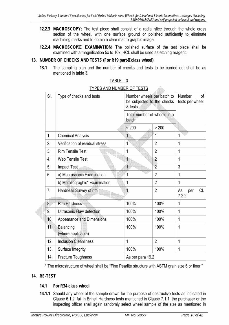
13. NUMBER OF CHECKS AND TESTS (For R19 part-II class wheel) 13.1 The sampling plan and the number of checks and tests to be carried out shall be as
mentioned in table 3. TABLE – 3
TYPES AND NUMBER OF TESTS Sl. Type of checks and tests Number wheels per batch to
be subjected to the checks & tests
Number of tests per wheel
Total number of wheels in a batch < 200 > 200
1. Chemical Analysis 1 1 1 2. Verification of residual stress 1 2 1 3. Rim Tensile Test 1 2 1 4. Web Tensile Test 1 2 1 5. Impact Test 1 2 3 6. a) Macroscopic Examination 1 2 1
b) Metallograghic* Examination 1 2 1 7. Hardness Survey of rim 1 2 As per Cl.
7.2.2 8. Rim Hardness 100% 100% 1 9. Ultrasonic Flaw detection 100% 100% 1 10. Appearance and Dimensions 100% 100% 1 11. Balancing
(where applicable) 100% 100% 1
12. Inclusion Cleanliness 1 2 1 13. Surface Integrity 100% 100% 1 14. Fracture Toughness As per para 19.2
* The microstructure of wheel shall be “Fine Pearlite structure with ASTM grain size 6 or finer.”
14. RE-TEST
14.1 For R34 class wheel: 14.1.1 Should any wheel of the sample drawn for the purpose of destructive tests as indicated in
Clause 6.1.2, fail in Brinell Hardness tests mentioned in Clause 7.1.1, the purchaser or the inspecting officer shall again randomly select wheel sample of the size as mentioned in

Indian Railway Standard Specification for Solid Rolled Multiple Wear Wheels for Diesel and Electric locomotives, carriages (including EMU/DMU/MEMU and self propelled vehicles) and wagons
Motive Power Directorate, RDSO, Lucknow MP No. xxxxx Page 11 of 42
Clause 6.1.2 from the same lot with or without re-heat treatment. Any re-heat treatment shall require purchaser or inspecting officer’s prior permission. The sample wheels shall be accepted if the results of these further tests are satisfactory. Should any of the retested wheels fail to fulfill the conditions of Brinell Hardness test, the sample will be rejected. In such eventuality, the manufacturer may segregate good wheels after 100% hardness check and offer the good wheels for drawing sample for other subsequent tests. Should the sample of the lot which has passed Brinell Hardness tests of Clause 7.1.1, fail in residual stress test, the manufacturer may, with the concurrence of the purchaser or inspecting officer, reheat treat the lot and present it again for Brinell Hardness tests of Clause 7.1.1 and residual tests with double the sample size as mentioned in Clause 6.1.2. Should the sample fail in any of the tests, the lot shall be rejected. Should the results of these repeat tests prove satisfactory, the lot from which the wheels were selected shall be accepted. Should the sample of the lot which has passed Brinell Hardness tests of Clause 7.1.1, residual stress test, fail in cut-section Brinell Hardness tests mentioned in Clause 7.1.3, two more sets of cut-section hardness tests be made from two wheels of the same lot for repeat tests. The wheels shall be accepted if the results of these further tests are satisfactory. Should the repeat cut-section hardness tests not prove satisfactory, the manufacturer may, with the concurrence of the purchaser or inspecting officer, reheat treat the lot and present it again for Brinell Hardness test of Clauses 7.1.1, residual stress test and cut section Brinell Hardness tests with double the sample size as mentioned in Clause 6.1.2. Should the sample fail in any of these tests, the lot shall be rejected. Should the results of these repeat tests prove satisfactory, the lot from which the wheels were selected shall be accepted. Should the sample of the lot which has passed Brinell Hardness tests of Clause 7.1.1, residual stress test and cut section Brinell Hardness test, fail in tensile tests, two more sets of tensile test pieces shall be taken from two wheels of the same lot for repeat test. The wheels shall be accepted if the results of these further tests are satisfactory. Should the repeat tensile tests not prove satisfactory, the manufacturer may, with concurrence of the purchaser or the inspecting officer, reheat treat the lot and present it again for Brinell Hardness test of Clause 7.1.1, residual stress test, cut section Brinell Hardness test and tensile tests with double the sample size as mentioned in Clause 6.1.2. Should the sample fail in any of the tests, the lot shall be rejected. Should the results of these repeat tests prove satisfactory, the lot from which the wheels were selected shall be accepted. Should the sample of the lot which has passed Brinell Hardness tests of Clause 7.1.1, residual stress test, cut section Brinell Hardness test and tensile test, fail in impact test, two more sets of impact test pieces shall be taken from two wheels of the same lot which has given the defective impact test results for repeat tests. The lot shall be accepted if the results of these repeat tests are satisfactory on both the wheels. Should the repeat impact tests not prove satisfactory, the manufacturer may, with the concurrence of the purchaser or the inspecting officer, reheat treat the lot and present it again for Brinell Hardness tests of Clause 7.1.1, residual stress test, cut section Brinell Hardness test, tensile test and impact test with double the sample size as mentioned in Clause 6.1.2. Should the sample fail in any of these tests, the lot shall be rejected. If the results of these repeat tests prove satisfactory, the lot from which the wheels were selected shall be accepted. Should the sample of the lot which has passed Brinell Hardness tests of Clause 7.1.1, residual stress test,cut section Brinell Hardness test, tensile test, and impact test fail in microstructure, the manufacturer may, with the concurrence of the purchaser or the inspecting officer, reheat treat the lot and present it again for Brinell Hardness tests of Clause 7.1.1, residual stress test, cut section Brinell Hardness test, tensile test, impact test and microstructure with double the sample size as mentioned in Clause 6.1.2. Should the
Indian Railway Standard Specification for Solid Rolled Multiple Wear Wheels for Diesel and Electric locomotives, carriages (including EMU/DMU/MEMU and self propelled vehicles) and wagons
Motive Power Directorate, RDSO, Lucknow MP No. xxxxx Page 12 of 42
sample fail in any of these tests, the lot shall be rejected. If the results of these repeat tests prove satisfactory, the lot from which the wheels were selected shall be accepted.
14.1.7 In Para 14.1.1 to14.1.6, reheat treatment has been allowed as a correction measure for getting correct values of any particular property in which wheels may have failed. However, any particular lot shall not be reheat treated more than twice to meet the full requirement of this specification.
14.1.8 Surface condition after reheat treatment subsequent to final machining: It is preferable to conduct the destructive tests before machining of the lot so as to avoid damage to the machined surface if reheat treatment is done. Reheat treatment on machined wheel, if permitted, shall be carried in such a manner that there is no loose scale formation. Only adherent oxide film should form. With such adherent film formation, no machining or other mechanical operation is required, discoloration of machined surface notwithstanding.
14.2 For R19 part-II class wheel: 14.2.1 Should a wheel fail in any of the above tests the purchaser or the inspecting officer shall
select two more wheels from the same lot, and all of which may, with his permission, be reheat treated before the selection is made. Should either of the re-tested wheels fail to fulfill the conditions of any of the above tests, the manufacturer may, with the concurrence of the purchaser or the inspecting officer, reheat treat the bulk again, from which the purchaser or the inspecting officer shall select two more wheels for further tests. Should the results of these repeat tests be satisfactory, the wheels represented shall be held to have passed the test. Should either of these wheels fail to fulfill the conditions of the test, the wheels represented shall be rejected. Only two reheat treatments shall be permitted in all.
15. NORMAL AND TIGHTENED INSPECTION for R34 class wheel Tests on the wheels shall be carried out either in normal or in tightened manner. 15.1 Normal inspection: In normal inspection, the sample size shall be as per Clause 6.1.2
and retests as per Clause 14.1 may be permitted. 15.2 Tightened inspection: In tightened inspection, the sample size shall be double the size
mentioned in Clause 6.1.2 and no retest shall be permitted. 15.3 The following criteria shall be applied for changing from normal to tightened inspection and
vice versa. a. If, while on normal inspection, 2 out of 5 (or less) consecutive lots have been rejected
or have been accepted after one or more retests as per Clause 14.1, change over to tightened inspection.
b. If, while on tightened inspection, 5 consecutive lots have been accepted, change over to normal inspection.
16. ULTRASONIC TESTS 16.1 For R34 class wheel All the wheels conforming to the stipulation of the above-mentioned
clauses shall be subjected to ultrasonic testing and only those passing the test shall be accepted. Ultrasonic testing will be done after final heat treatment and machining operations. The method of testing and acceptance standard shall be as given in Appendix “A”.
16.2 For R19 part-II class wheel: All the wheels confirming to the stipulation of the above-mentioned clauses shall be subjected to ultrasonic testing and only those passing the test

Indian Railway Standard Specification for Solid Rolled Multiple Wear Wheels for Diesel and Electric locomotives, carriages (including EMU/DMU/MEMU and self propelled vehicles) and wagons
Motive Power Directorate, RDSO, Lucknow MP No. xxxxx Page 13 of 42
shall be accepted. Ultrasonic examination shall be done using on line testing equipment for 100% wheels. The equipment shall have facility for documentation of wheel Sr. No. vis-a-vis U.T. operator. The method of testing and acceptance standard shall be as given in Appendix `B’.
16.2.1 Ultrasonic testing can also be carried out in phased array method, as per AAR-M107/208 specification, as an alternative method.
17. MAGNETIC PARTICLE TESTS 17.1 For R34 class wheel: All the wheels shall be tested by magnetic particle method to ensure
soundness of the wheels at web region. Magnetic particle testing shall be done after final heat treatment and machining operations. Both sides of the wheel web (plate) shall be inspected through this method. The method of testing and acceptance standard shall be as given in Appendix “C”.
17.2 For R19 part-II class wheel: SURFACE INTEGRITY
17.2.1 GENERAL Surface integrity shall be determined by a magnetic particle test.
17.2.2 LEVEL TO BE ACHIEVED The maximum indicated length of permissible surface breaking defects shall be, as follows, unless otherwise defined in the order. • 2 mm on machined faces, • 6 mm on black faces either forged or rolled.
17.2.3 TEST PIECE Examination shall be made on the complete wheel after heat treatment, in the finished or part finished machined condition before corrosion protection is applied.
17.2.4 METHODS OF INSPECTION 17.2.4.1 General requirements for the magnetic particle test shall be defined according to IS: 3703-
1998, except that: • The level of the surface magnetic induction shall be greater than 4 mT. • The level of the lighting energy of ultra-violet light shall be greater than 15W/m3.
17.2.4.2 The apparatus used shall scan the entire wheel surface and be able to detect the defects whatever their orientation.
17.2.5 The magnetic particle tests as per ISO 6933 / AAR 107/208 is also allowed as an alternative method. The judgment criteria shall be same as clause 17.2.1. The sampling plan and the number of checks and tests shall be as per table 3 of this specification.
18. ADDITIONAL TESTS The purchaser or inspecting authority may, in case of reasonable doubt, also resort to other forms of testing as mutually agreed to between the purchaser or inspecting authority and the manufacturer is to satisfy that the wheels are free from defects of any kind.
Indian Railway Standard Specification for Solid Rolled Multiple Wear Wheels for Diesel and Electric locomotives, carriages (including EMU/DMU/MEMU and self propelled vehicles) and wagons
Motive Power Directorate, RDSO, Lucknow MP No. xxxxx Page 14 of 42
19. TOUGHNESS CHARACTERISTIC OF RIM
19.1 For R34 class wheel: 19.1.1 Fracture toughness at rim: The test shall be carried out in accordance with ASTM
standard E: 399. Five test samples shall be taken from points evenly distributed over the whole rim and as shown in Fig. 3. The fracture toughness value at 25 ± 5ºC under consideration shall be the value KQ. The average value calculated from the 5 measurements of KQ shall be minimum 60 MPa√m with no individual value below 50 MPa√m.
19.1.2 The above test at Clause 19.1.1 shall be carried out, when a supplier is supplying this type of wheel for the first time to Indian Railway or when specifically mentioned in the contract by the purchaser and shall be generally applicable to the bulk suppliers each supplying more than 2,500 wheel discs in a contract. The fracture toughness test will be conducted for every 10,000 wheel discs. If the manufacturer does not have the requisite facility to carry out this test, the services of any reputed agency as agreed by the purchaser / inspecting authority can be availed of.
19.2 For R19 part-II class wheel: 19.2.1 This test shall be carried out on one in every 3000 wheels or part thereof for a supplier who
has qualified as per clause 25.1 of the specification. For other manufacturer/supplier, who has not qualified, the test shall be carried out on one in every 500 wheels or part thereof upto first 3000 wheels.
19.2.2 Values To Be Achieved: The average value obtained from six test pieces shall be greater than or equal to 80 N/mm²√m, and any single value shall not be below a minimum of 70 N/mm²√m. Six test pieces shall be taken from the rim as indicated in figure 3. The test pieces shall be evenly distributed around the rim.
19.2.3 TEST METHOD: The test shall be performed according to ASTM E 399/90. The particular conditions which shall be used are as follows: • Compact specimen CT: thickness of 30 mm (CT 30 specimen), with chevron notch with
an aperture angle of 90º (figure 4 ASTM E 399/90). • Temperature during the test to be between +15 ºC and +25 ºC. • Measurement of the crack displacement of the specimen as indicated in figure 3 of
ASTM E 399/90 • Rate of increase of stress intensity ΔK/s should be within the range from 0.55 N/mm²√m
/s to 1 N/mm²√m /s (clause 8.3 of ASTM E 399/90) The value of the toughness to be considered shall be the value KQ which is calculated from the value of the load FQ from the load-displacement record
20. Balancing Test 20.1 For R34 class wheel: The test specimen shall consist of the finished wheel. This test shall
be applicable only in case it is specified in the drawing/ purchase order, and will require to be done in all such wheels.
20.2 For R19 part-II class wheel: The test specimen shall consist of the finished wheel. This test shall be applicable only in case specified in the purchaser order. The balancing of each wheel shall be checked by means and methods agreed to between the purchaser and manufacturer. RESIDUAL IMBALANCE: Unless otherwise specified in the order or its appended documents, the out of balance moment of the finished wheel shall not exceed the limits indicated in Table-4. For this purpose, the finished wheels shall mean where all parts of the

Indian Railway Standard Specification for Solid Rolled Multiple Wear Wheels for Diesel and Electric locomotives, carriages (including EMU/DMU/MEMU and self propelled vehicles) and wagons
Motive Power Directorate, RDSO, Lucknow MP No. xxxxx Page 15 of 42
wheel required to be machined have undergone their final machining. The exception is the case of the bore which is normally finished machined by the manufacturer responsible for the final assembly of the wheel to the axle.
TABLE-4 LIMITS FOR OUT OF BALANCE MOMENT
Sl. Application Maximum residual imbalance in gm-m
1. Wheels for stock running at a speed > 200 Kmph. 50 2. Wheels for stock running at a speed >120 and < 200 kmph 75 3. Wheels for stock running at a speed < 120 Kmph. 125
21. INSPECTION The inspecting officer or the purchaser shall have free access to the works of the manufacturer at all
reasonable times; he shall be at liberty to inspect during any stage of manufacture and to reject any material not conforming to the terms of this specification. The inspecting officer or the purchaser shall have the authority to mark all the rejected wheels in an easily distinguishable manner so that such wheels cannot be recycled / re-offered for inspection in subsequent lots, but they shall not be marked in such a manner as to render them unsaleable to other parties
The purchaser or the inspecting officer reserves the right to be present at, and take part as he deems fit, in all analysis and other chemical and physical examinations / tests which the manufacturer may carry out, either for his own purpose or under the terms of this specification, on the wheels as well as on their materials, during all stages of manufacture.
22. TESTING FACILITIES The manufacturer shall supply, free of charge, the material required for testing, and shall, at his own cost, furnish & prepare necessary test pieces and supply labour & appliances for such testing as may be carried out at his premises in accordance with this specification. In case the manufacturer fails to provide facilities for conducting the prescribed tests at his works, he shall bear the cost of carrying out the tests elsewhere.
23. PROTECTION 23.1 For R34 class wheel After inspection and approval, the wheels shall be carefully cleaned of
all rust and protected with one coat of mineral oil to IS: 11546 (latest version) or red oxide primer or any other protective coating as agreed to between the purchaser and the supplier. Effective protection of finish machined parts of the wheels against impact damage during transit shall be ensured by the supplier before dispatch.
23.2 For R19 part-II class wheel 23.2.1 After inspection and approval, the wheels shall be cleaned of all rust, apply one coat of Red
Oxide Zinc Chrome Primer to IS: 2074 followed by one coat of Ready Mixed Paint, Finishing, Bituminous Black, Lead free, Acid, Alkali, Water and Chlorine Resistant to IS: 9862. The above method is applicable for the wheels except for the tread and rim areas.
23.2.2 The manufacturer may use any other suitable rust preventive compound subject to approval of Purchasing/Inspecting officer.
23.2.3 Effective protection of finish-machined parts of the wheels against impact damage during transit shall be ensured by the supplier before dispatch.
6 Temporary corrosion preventive, fluid, soft film, solvent deposited, water displacing

Indian Railway Standard Specification for Solid Rolled Multiple Wear Wheels for Diesel and Electric locomotives, carriages (including EMU/DMU/MEMU and self propelled vehicles) and wagons
Motive Power Directorate, RDSO, Lucknow MP No. xxxxx Page 16 of 42
24. GUARANTEE for R19 part-II class wheel 24.1 The wheel shall be guaranteed by the supplier for five years against any defect attributable to
the manufacture and not revealed during the acceptance inspection. 24.2 This period shall be calculated from the end of the month stamped on the wheel. 24.3 In case of wheels for new vehicles, the delivery date of the vehicles to which they are fitted
shall be regarded as the date of delivery of the wheels. 24.4 Wheels, which during their guarantee period show defect making them either unfit for service
or reducing their period of life will be rejected. 24.5 When two wheels from the same cast have failed in service, or when more than 5 % of the
wheels from the same cast reveal defects which are inherent to material quality including its soundness, the purchaser shall have the right to reject the entire cast.
24.6 Rejected wheels shall be made available to the supplier with a view to arrange their replacement or reimbursement.
25. MANUFACTURER’S QUALIFICATION / PRODUCT QUALIFICATION (for R19 part-II class wheel) 25.1 GENERAL 25.1.1 Before acceptance for regular use by Indian Railways, a wheel shall be qualified. 25.1.2 This clause defines the requirements and the procedures to be applied for the product
qualification. 25.1.3 Qualification of a wheel is directly linked to the supplier, and a wheel can only be
considered for qualification if the supplier follows the requirements defined in clause 25.2. 25.1.4 The requirements and the procedures of this clause apply only to wheels for which the
design has been approved: • Either by a previous use on Indian Railways; • Or by a recognized technical approval procedure
25.1.5 The requirements are to be applied in the following cases: • Any wheel from a new supplier; • Any nonqualified wheel from a supplier, when its geometry is appreciably different to
qualified wheels from this supplier (shape and thickness of the web, diameter, etc.) • Any change in the manufacturing process of a producer for a qualified wheel.
25.1.6 A supplier who has already supplied more than 3000 wheels of the tendered design to Indian Railways and minimum 300 numbers of such wheels have run satisfactorily for more than two years will be deemed to have qualified for the particular design and shall not require to undergo the qualification procedure as in para 25.0.
25.1.7 The manufacturers who are not qualified will not be given order for more than 3000 number of wheels. However, the limit of 3000 wheels may be exempted/relaxed for those internationally reputed wheel manufacturers whose wheels have run satisfactorily for at least five years on passenger coaches at speeds more than 160 kmph on any international railway system and have also supplied wheels of different design(s) to Indian Railways but conforming to this specification. Such supplier shall however, with his offer, submit evidence of conformance to Clause 25.2 of the specifications and furnish documentation in accordance with Clause 25.3.2.

Indian Railway Standard Specification for Solid Rolled Multiple Wear Wheels for Diesel and Electric locomotives, carriages (including EMU/DMU/MEMU and self propelled vehicles) and wagons
Motive Power Directorate, RDSO, Lucknow MP No. xxxxx Page 17 of 42
25.1.8 The limit of 3000 Nos. of wheels is to be treated as a regular order with a cap in case of non - qualified manufacturers, or vendors not covered under internationally reputed manufacturers.
25.1.9 If performance of wheels supplied by a qualified manufacturer is unsatisfactory, the manufacturer may be asked to re-qualify for supply to Indian Railways.
25.2 REQUIREMENTS 25.2.1 REQUIREMENTS FOR THE SUPPLIER 25.2.1.1 GENERAL 25.2.1.1.1 When manufacture of a wheel involves more than one supplier, the following
requirements shall be satisfied by all concerned. 25.2.1.2 QUALITY ORGANIZATION 25.2.1.2.1 The supplier shall operate a quality assurance system conforming to ISO 9001-2000. 25.2.1.3 STAFF QUALIFICATION 25.2.1.3.1 Staff trained in non-destructive testing shall be qualified in accordance with EN 473 or
JIS Z2305 or equivalent. 25.2.1.4 EQUIPMENT 25.2.1.4.1 The equipment used by the supplier for production, control and monitoring, shall allow
the requirements of this standard to be satisfied. 25.2.2 REQUIREMENTS FOR THE PRODUCT 25.2.2.1 The product shall be in accordance with the product requirements listed in this
specification. Traceability of each wheel must be established after its heat treatment. 25.3 QUALIFICATION PROCEDURE 25.3.1 GENERAL 25.3.1.1 The qualification procedure for the product comprises four successive stages.
• Provision of documents by the supplier; • Evaluation of the manufacturing equipment and production processes; • Laboratory tests; • Service experience of wheels.
25.3.2 DOCUMENTATION REQUIRED 25.3.2.1 At the time of tender, the manufacturer shall provide a document that comprises:
• A description of the wheel: • A description of the company stating:
- Company size (number of people employed, defining the proportion between manufacture, control and quality assurance),
- Production per year of all products, - A list of all the means of manufacture and quality control;
• Data about the company organization with the appropriate organization charts; • A description of manufacturing processes with descriptions of the different stages
of manufacturing; • Details of supplies to Indian Railways, if the product has been previously qualified. • Bidders/Manufacturers shall submit the details in support of their qualification as
“Internationally reputed manufacturer” in the format below.

Indian Railway Standard Specification for Solid Rolled Multiple Wear Wheels for Diesel and Electric locomotives, carriages (including EMU/DMU/MEMU and self propelled vehicles) and wagons
Motive Power Directorate, RDSO, Lucknow MP No. xxxxx Page 18 of 42
Sl. Purchase Order Number and Date
Name of Passenger Service (with Operation Speed > 160kmph)
Date of Supply
Quantity Supplied
Details of Wheels Supplied to Indian Railways conforming to this specification.
25.3.3 Evaluation of Manufacturing Equipment and the Production Processes 25.3.3.1 This evaluation comprises:
• An inspection of the manufacturing plant and examination of the process. • An inspection of the raw material manufacturing plant and examination of its
production process. • Auditing of the manufacturing organization against the requirements of 25.2.1 • Auditing of the information provided in the documents referred to in 25.3.2. • Data about raw materials with the list of suppliers;
25.3.4 Laboratory Tests 25.3.4.1 All characteristics defined in this specification, shall be proven on wheels produced by
the manufacturer’s standard processes given in QAP. The number of samples to be tested will be as specified in table 4 of this specification.
25.3.4.2 A report shall be drawn up at the end of this stage, describing the test pieces, the test carried out as well as test results. It shall specify whether or not the wheels are in compliance with the requirements.
25.3.5 Testing Of Wheels 25.3.5.1 Operational Testing 25.3.5.1.1 The first minimum 300 number of wheels supplied shall be specially monitored in service
as per monitoring scheme given in appendix D. It shall contain: • Type and extent of intermediate and final inspections; • Time period for the testing.
25.3.5.2 Results of Testing 25.3.5.2.1 The product (wheel to a particular design) shall be deemed as qualified at the earliest
after two years after the first 300 wheels have entered service, provided that the performance recorded does not deviate repeatedly from the acceptance criterion given in table 3 of clause 13 of this specification.
25.4 Qualification 25.4.1 Based on the successful completion of the above, the manufacturer will be qualified for
supply of wheels to Indian Railways. The qualification shall be limited in validity for: • Wheels diameters; • Web thickness and shapes.
25.4.2 If the customer records significant defects on the product, the relevant parts of the qualification procedure shall be repeated.
25.4.3 If the supplier has not respected important conditions of the qualification, it may be cancelled.

Indian Railway Standard Specification for Solid Rolled Multiple Wear Wheels for Diesel and Electric locomotives, carriages (including EMU/DMU/MEMU and self propelled vehicles) and wagons
Motive Power Directorate, RDSO, Lucknow MP No. xxxxx Page 19 of 42
APPENDIX ‘A’ METHOD OF ULTRASONIC TESTING & ACCEPTANCE STANDARD
For R34 class wheel: (Clause 16.1)
For detecting internal discontinuities in the rim and hub of the wheel, ultrasonic inspection shall be carried out by following the procedure shown below and by using equipment which complies with the following requirements. Reference standard used for sensitivity setting shall be from wheels conforming to this standard. The surface finish of probing face shall be in accordance with the relevant wheel drawing. The ultrasonic inspection shall be performed after final thermal and machining operations.
A-1 ULTRASONIC TESTING ON WHEEL RIM The rims of the wheels shall be checked through ultrasonic inspection to detect the defects at two orientations: i. Defect parallel to the rim face (axial testing) ii. Defect parallel to the running tread (radial testing)
A-1.1 AXIAL TESTING All wheels shall be subjected to ultrasonic testing of rim through probing axially along the rim face to detect any flaw having orientation parallel to the rim face.
.1 Equipment .1 Automatic ultrasonic testing equipment shall be used. The instrument shall have a pulse
echo transmitter & receiver and shall have an operating frequency range of 2 to 5 MHz. The manufacturer shall have on-line test facility to inspect 100% wheels. For determination of final rejection, manual ultrasonic equipments approved by the purchaser may be employed.
.2 The transducers shall be of normal (0 degree) type comprising of high sensitivity Piezo electric ceramic crystal operating at 2 to 2.5 MHz frequency and of 18-20 mm diameter.
.3 An automatic flaw alarm system shall be used in conjunction with the ultrasonic instrumentation to facilitate flaw indication beyond acceptable level.
.4 An immersion or contact type testing technique shall be used in automatic on-line testing. For manual testing of suspect wheels, a suitable couplant shall be used between the test surface and the transducer. In case of dispute in respect of couplant, the decision of the inspecting officer shall be final and binding.
.5 Calibration block: 50mm x 50mm x 50mm block of steel to grade 45C8 of IS:1875 7 shall be used. Alternatively, this calibration block can be made of portion of the heat-treated wheel of steel grade confirming to the specification IRS R-34.
.6 Standard reference piece: Standard reference piece shall be from a portion of the wheel having a 3mm diameter flat bottom hole drilled perpendicular to the rim face and to a depth of 25 ± 2mm at the mid thickness of the rim (Fig 4.1).
.7 Alternate reference piece: Alternate reference piece shall be from a portion of the wheel having a small diameter hole of diameter 3mm drilled at a distance from the testing surface equal to the depth of the hole indicated in A-1.1.1.6 (Fig. 4.2). The instrument shall be adjusted to give an equal test value to that of a 3mm diameter flat bottom hole.
7 Carbon Steel billets, blooms, slabs and bars for forgings

Indian Railway Standard Specification for Solid Rolled Multiple Wear Wheels for Diesel and Electric locomotives, carriages (including EMU/DMU/MEMU and self propelled vehicles) and wagons
Motive Power Directorate, RDSO, Lucknow MP No. xxxxx Page 20 of 42
.2 Calibration .1 Time base: Set the time base of ultrasonic flaw detector using 0 degree longitudinal
wave with the help of calibration block as mentioned in Para A-1.1.1.5. Three multiple echoes will be observed.
.2 Sensitivity setting: Sensitivity setting shall be done with the help of standard wheel piece (Fig. 4.1). Gain level should be adjusted to produce 60% height from the reference standard as mentioned in Para A-1.1.1.6.
.3 Alternatively, sensitivity setting shall be done with the help of an alternate reference piece as mentioned in Para A-1.1.1.7 (Fig. 4.2) and shall be used only with the specific approval of the purchaser.
.4 Reference standard for the inspection of heat-treated wheels shall be fabricated from heat-treated wheels.
.3 Scanning .1 Wheels shall be inspected axially from either the outside or inside rim face by automatic
scanning (Fig. 4.1 and 4.2). For determining acceptance or otherwise, probing from both sides may be carried out.
.2 The speed of scanning shall permit efficient detection of the reference standard discontinuities.
.4 Rejection criteria .1 Any wheel with a flaw indication equal to or larger than 60% of the full-scale height shall
be rejected. If more than 3 defects of amplitude 20% or above are observed, the wheel shall be rejected. If two defects of amplitude 20% or above are observed, and if these defects are closer than 50 mm, the wheel shall be rejected.
.2 Ultrasonic indications that result from wheel geometry or spurious signal shall not be valid cause for rejection. The judgement of the inspecting officer shall be final and binding in this respect.
.3 The final disposal of rejection of wheels may be determined by manual testing of disputed areas. The surface finish of rim of reference standard will be almost same as that of wheels tested manually by contact probing.
A-1.2 RADIAL TESTING All wheels will be subjected to ultrasonic testing of rim through probing circumferentially along the tread surface to detect any flaw having orientation parallel to the tread surface. .1 Equipment
.1 Equipment shall be same as described in Clause A-1.1.1.
.2 Calibration Block: 50x50x50mm block of steel to grade 45C8 of IS: 1875 shall be used. Alternatively, this calibration block can be made of portion of the heat-treated wheel of steel grade confirming to the specification IRS R-34.
.3 Standard reference piece: Reference piece shall be from a portion of new wheel having 3mm diameter flat bottom hole drilled from opposite to tread surface (Fig. 5) to depth of 20mm.
.2 Calibration .1 Time Base: Set the time base of ultrasonic flaw detector using 0 degree longitudinal
wave with the help of calibration block as mentioned in Para A-1.2.1.2. Three multiple echoes shall be observed.

Indian Railway Standard Specification for Solid Rolled Multiple Wear Wheels for Diesel and Electric locomotives, carriages (including EMU/DMU/MEMU and self propelled vehicles) and wagons
Motive Power Directorate, RDSO, Lucknow MP No. xxxxx Page 21 of 42
.2 Sensitivity setting: Sensitivity setting shall be done with the help of standard wheel piece as mentioned in Para A-1.2.1.3 (Fig.5). Probing shall be done from the tread opposite to flat bottom hole and the gain level shall be adjusted to produce an echo of 60% height of vertical scale of CRT. This gain level shall be reference gain for acceptance or otherwise for the wheel.
.3 Scanning Increase the gain level by 6dB over and above the gain level described at Para A-1.2.2.2. Apply couplant on the tread surface, place the probe on this face and scan entire circumference on the wheel in case of contact type automatic scanning equipment. For immersion type of equipment, the wave propagation shall be through the liquid used for immersing the wheel. No back echo will appear. Care shall be taken during probing to cover full width of the tread. In case a flaw signal is observed, reduce the gain by 6dB.
.4 Rejection criteria Any wheel with a flaw indication equal to or larger than 60% of the full-scale height shall be rejected. If more than 3 defects of amplitude 20% or above are observed, the wheel shall be rejected. If two defects of amplitude 20% or above are observed and if these defects are closer than 50 mm, the wheel shall be rejected.
.5 The final disposal of rejection of wheels may be determined by manual testing of disputed areas. The surface finish of tread of reference standard shall be almost same as that of wheels tested manually by contact probing.
A-2 ULTRASONIC TESTING ON WHEEL HUB Only such wheels, which pass ultrasonic test for the rim, shall be subjected to ultrasonic testing of hub.
A-2.1 EQUIPMENT Equipment shall be the same as used for ultrasonic testing of the rim portion of the wheels, suitably calibrated for hub thickness. However, manual testing of hub will be permitted. For hub testing, the back wall echo shall be adjusted to full screen height using a wheel hub free from internal discontinuities. Surface finish of reference piece shall be similar to wheels tested if manual testing is resorted to.
A-2.2 REJECTION CRITERIA 1. Any wheel with a flaw indication equal to or larger than 60% of the full-scale height shall be
rejected. If more than 2 defects of amplitude less than 60% and greater than 20% are observed, the wheel shall be rejected. If two defects of amplitude less than 60% and greater than 20% are observed, and if these defects are closer than 50 mm, the wheel shall be rejected.
2. Where there is a partial suppression of the back echo and flaw echo is also absent, the back echo shall not be less than 30% of the full screen height without change of testing parameters.
A-3 MARKING Wheel conforming to the above ultrasonic stipulations shall be stenciled “UT” on the back plate with red colour paint using characters at least 25 mm in height or at such locations as may be shown on the drawing or specified by the purchaser.

Indian Railway Standard Specification for Solid Rolled Multiple Wear Wheels for Diesel and Electric locomotives, carriages (including EMU/DMU/MEMU and self propelled vehicles) and wagons
Motive Power Directorate, RDSO, Lucknow MP No. xxxxx Page 22 of 42
APPENDIX -‘B’
(Clause-16.2)
Method of Ultrasonic Testing and Acceptance standard for Wrought Steel Wheels For R19 part-II class wheel
B-1 For detecting radial defects and flaws oriented circumferentially in the rims of wrought steel wheels, ultrasonic inspection shall be made by following the procedure shown below and by using equipment which complies with the following requirements.
B-2 Equipment B-2-1 The instrument shall have a pulse echo transmitter and receiver and shall have an operating
frequency range of 2 to 5 MHz. for the test method employed. Ultrasonic examination shall be carried out using on line facility. For determination of final rejection, manual Ultrasonic equipments approved by the purchaser may be employed.
B-2-2 The transducers shall be of normal (0°) type composed of highly sensitive Piezo-electric ceramics crystal operating 2 to 2.5 MHz. and of 18-20 mm diameter.
B-2-3 An automatic flaw alarm system shall preferably be used in conjunction with the Ultrasonic instrumentation.
B-2-4 A suitable couplant shall be used between the test surface and the transducer. An immersion testing technique could be used to facilitate automatic in line testing.
B-2-5 Calibration Block: 50x50x50 mm Block of steel to grades 45C8 of IS: 1875. B-2-6 Standard reference blocks: Reference blocks shall be made from wheel conforming to this
standard in all respects. (a) For rim testing- For rim testing the reference standard block shall be taken from the
portion of rim having 3.2mm dia. flat bottom hole drilled perpendicular to the rim face and to the depth of 25 ± 2 mm. at the mid thickness of the rim. see Fig.8 (a). An alternate reference block may also be used as mentioned in Fig. 8 (b).
(b) For tread testing – For tread testing the reference standard block shall be taken from a portion of wheel having 3.2 mm dia. flat bottom hole drilled from opposite to tread surface Fig. 9 to the depth of 20 ± 2 mm. The tread surface of the reference piece shall be free from rough turning marks and surface finish shall be 6.3 microns or better.
B-3 Time of Inspection Inspection shall be performed after final thermal processing. B-4 Procedure for range Calibration and sensitivity setting. B-4-1 Set the time base of Ultrasonic Flaw detector using 0° longitudinal wave with help of Calibration
block as mentioned in para B-2-5 for 200 mm. B-4-2 Sensitivity setting
(a) For rim testing the instrument sensitivity level shall be adjusted to produce an echo of 60% height of vertical scale of CRT using standard reference block as mentioned in para B-2-6 (a). This gain level shall be reference gain for acceptance or otherwise for the wheel.
(b) For testing from tread, the instrument Sensitivity level shall be adjusted to produce an echo of 60% height of vertical scale of CRT using standard reference block as mentioned in para B-2-6 (b).This gain level shall be reference gain for acceptance or otherwise for the wheel.

Indian Railway Standard Specification for Solid Rolled Multiple Wear Wheels for Diesel and Electric locomotives, carriages (including EMU/DMU/MEMU and self propelled vehicles) and wagons
Motive Power Directorate, RDSO, Lucknow MP No. xxxxx Page 23 of 42
B-5 Scanning B-5-1 Wheels shall be inspected axially from either the front or back rim face by manual or automatic
scanning See Fig. 8 (a) & 8 (b). B-5-2 One or more transducers shall be designed and located to give maximum coverage of the rim
section. Maximum possible area shall be scanned. B-5-3 In case of automatic scanning the speed of scanning shall permit detection of the reference
standard discontinuities. B-5-4 Wheels shall also be inspected by probing from the tread surface as per the procedure
mentioned below: B-5-4-1 Increase the gain level by 6 dB over and above the gain level described at para B-4-2 (b). B-5-4-2 Apply couplant on the tread surface, place the probe on this face and scan entire circumference
of the wheel no back echo will appear on the screen. B-5-4-3 Care shall be taken during probing to cover full width of the tread.
B-5-4-4 In case flaw signal is observed reduce the gain by 6dB. B-6 Rejection criteria B-6-1 Any wheel with an individual flaw indication equal to or larger than that obtained from the
reference discontinuities shall be cause for rejection (in both case i.e. probing from rim side or from tread).
B-6-2 The number of flaw signal of amplitude between 20% to 60% shall not be more than 5 probing location for tread & rim combined.
B-6-3 The distance between two consecutive defects shall not be less than 20 mm if it is less, it will be a cause for rejection.
B-6-4 Ultrasonic indications resulting from wheel geometry or spurious signals due to other reasons shall not be a valid cause for rejection. In the event of any dispute regarding the nature of signal, the decision of the Inspecting authority shall be final and binding.
B-6-5 When automated equipments are employed, the final disposal of the rejectable wheel may be determined by Manual testing of questioned area.
B-7 Marking B-7-1 Wheels conforming to the above stipulation shall be marked /stamped UT as a token of
acceptance. Wheels not conforming to the stipulation shall be defaced and records for the same maintained.

Indian Railway Standard Specification for Solid Rolled Multiple Wear Wheels for Diesel and Electric locomotives, carriages (including EMU/DMU/MEMU and self propelled vehicles) and wagons
Motive Power Directorate, RDSO, Lucknow MP No. xxxxx Page 24 of 42
APPENDIX 'C' METHOD OF MAGNETIC PARTICLE TESTING & ACCEPTANCE STANDARD
For R34 class wheel (Clause 17.1)
C. MAGNETIC PARTICLE TESTING C.1 PURPOSE
To supplement visual inspection of the surface of new wheels by detecting discontinuities which may be harmful to wheel in service.
C.2 SCOPE This test method covers the wet fluorescent magnetic particle inspection of plates of the wheels ordered to this specification.
C.3 EQUIPMENTS .1 Magnetizing Apparatus
The magnetizing apparatus shall be on line and shall be capable of inducing suitable magnetic fields within the entire plate area of the wheel to facilitate the disclosure of both circumferentially and radially oriented discontinuities. The magnetizing currents used shall be large enough to induce magnetic fields of sufficient intensity to disclose surface discontinuities 0.3 mm in depth. Any non-metallic entrapment on surface shall also get detected.
.2 Lighting Apparatus The inspection shall be performed in a darkened booth with the area of the wheel to be inspected illuminated with properly filtered black light. The black light shall have a predominant wavelength of 4,000 to 3,400 angstrom units and the intensity of the black light, measured at the surface to be inspected, shall be a minimum of 75 foot-candles at point of inspection.
.3 Inspection Medium .1 The bath or solution shall be prepared using a suitable carrier fluid & fluorescent
magnetic particles and renewed monthly or more often if contamination is noted in weekly tests. Each time the bath is renewed, the bath container shall be cleaned out and the agitation & circulation system should be flushed with 5 to 8 litres of clean carrier. Filtering screens shall be removed and cleaned by blowing with air. In preparing the new bath, only recommended materials shall be used. The amount of powder shall be carefully weighed out in accordance with the material manufacturer’s recommendation and the powder shall be directly added to the bath containing the correct amount of carrier. It is recommended that powder be added directly over the sump so that it shall be drawn quickly into the pump and circulated. The amount of carrier & powder used and the date of preparation shall be recorded on a regular form set up for this purpose, as outlined in paragraph B.3.3.6.
.2 Concentration and contamination of the bath solution shall be tested weekly as follows: The pump and agitation system shall be operated for 20 minutes and then solution should be run through hose and nozzle for 30 seconds. Using a regular 100 ml centrifuge tube, fill the centrifuge tube with 100 ml of the solution. Allow bath solution to settle for the time recommended by the manufacturer of the type of powder used making sure that the tube is not subjected to excessive vibration during the settling

Indian Railway Standard Specification for Solid Rolled Multiple Wear Wheels for Diesel and Electric locomotives, carriages (including EMU/DMU/MEMU and self propelled vehicles) and wagons
Motive Power Directorate, RDSO, Lucknow MP No. xxxxx Page 25 of 42
period. Each horizontal division represents 0.1 ml and correct reading in volume of particles shall be as stipulated by the powder manufacturer. Check shall also note contamination due to dirt, chips or other foreign matter settling with the powder. Contamination is also indicated when the carrier appears to acquire more than usual fluorescence or when the magnetic particles appear to have lost fluorescent qualities. This condition can be readily observed when the settling tube is exposed to ultraviolet light. The readings obtained are to be shown on the regular report form as outlined in paragraph B.3.3.6.
.3 The ultraviolet light shall be tested weekly using a light meter, such as a type having foot candle scale with 10X multiplying disc or equivalent or a meter that responds specifically to the ultraviolet range of 3,650 angstrom units (365 nanometers). The latter type meters are calibrated in microwatts per square centimetre. The meter shall be held at a fixed distance of 380 mm from the light source (from black light filter surface to meter sensing element) and shall have a minimum meter reading of 525 microwatts per square centimetre.
.4 The conversion factor from foot candles (for light meters) to microwatts per square centimetre is 5.7 times the foot candle reading (at 380 mm distance).
.5 The maximum allowable foot candles shall be left to the discretion of the user depending on the degree of brilliance desired to obtain satisfactory inspection conditions. Before taking reading, it shall be ensured that the glass black light filters are clean. Reports of this test shall be shown on regular form as outlined in paragraph C.3.3.6.
.6 A regular form shall be prepared embodying the information to be shown on monthly and weekly tests as outlined above and this form shall be on hand at the wheel shop and available to inspectors.
.4 Preparation for Inspection The surface shall be scale free before magnetic particle inspection. The wheels shall be in machined condition.
.5 Detection of Discontinuities This inspection shall be performed to detect discontinuities whose axes may be in any direction. Continuous or residual magnetization shall be used with adequate coverage by the inspection medium.
.6 Time of Inspection The magnetic particle inspection shall be performed following final machining. A wheel / wheels with standard defects will be run at start of the shift to see that detection system is functional.
.7 Rejection Discontinuities may be removed by machining or grinding where sufficient stock remains. Such wheels shall be retested by magnetic particle inspection. Wheels where spot grinding has to be resorted to, shall be so ground that the area ground is at least 10 times the depth to avoid deep pit formation. The edges of the ground area shall be smooth and rounded. Maximum depth of grinding is 3mm. However, it shall be ensured that after grinding, the minimum dimensions at any spot are within the stipulated dimension in the wheel drawing. The wheel which has crack(s) which could not be removed even after grinding upto a depth of 3mm shall be rejected. If entrapment material is seen even after grinding to a depth of 3mm, wheel shall be rejected. If a crack is seen on bore, the wheel may be allowed to be bored upto allowable maximum bore and again put up for magnetic particle inspection.

Indian Railway Standard Specification for Solid Rolled Multiple Wear Wheels for Diesel and Electric locomotives, carriages (including EMU/DMU/MEMU and self propelled vehicles) and wagons
Motive Power Directorate, RDSO, Lucknow MP No. xxxxx Page 26 of 42
APPENDIX – ‘D’
MONITORING SCHEME FOR QUALIFICATION OF FORGED WHEELS OF NON-QUALIFIED MANUFACTURERS
(Clause-25.3.5.1 ) (For R-19Part II class wheel)
1. OBJECTIVES
As specified under clause 25.1.1 of R-19 Part II class wheel, Before acceptance for regular use by Indian Railways, a wheel shall be qualified. As per clause 25.1.6 supplier who has already supplied more than 3000 wheels of the tendered design to Indian Railways and minimum 300 numbers of such wheels have run satisfactorily for more than two years will be deemed to have qualified for the particular design and shall not require to undergo the qualification procedure as in para 25.0. As per clause 25.3.5.1.1 of R-19Part II class wheel, the first 300 Nos. of wheels supplied shall be specially monitored in service.
2. REPORTING RAILWAYS User Railways will nominate one officer and a supervisor to co-ordinate and monitor the service performance.
3. NUMBER AND TYPE OF ROLLING STOCK 300 Nos. of prototype forged wheels manufactured as per. R-19Part II class wheel shall be fitted on Carriages/Wagons/EMU stock of Indian Railways by user Railway. The rolling stock numbers on which wheel sets have been fitted should be recorded in the Proforma-I.
4. PERIOD OF MONITORING Monitoring period for field service of first 300 Nos. of non-qualified wheels will be 2 years. The frequency of monitoring of these wheels shall be half yearly (6 months). In the first inspection of monitoring, if certain defects are noticed the service period shall be increased suitably.
5. AGENCY FOR SUBMISSION OF REPORTS GM (Mechanical/Electrical) of user Railway shall submit reports to RDSO.
6. COORDINATING OFFICER AT RDSO Director Standards (SS)/Carriage, RDSO, Lucknow (Mob. No. 9794863104) will be the overall Co-ordinator.
7. FITMENT OF WHEELS AT WORKSHOPS a. Wheels shall be fitted on Carriages/Wagons/EMU stock of Indian Railways in accordance
with Para 3 and details submitted to RDSO. b. For easy identification of the wheels, it should be ensured that the wheels are painted
yellow on both sides of the web and following legend is painted with blue paint on the bogie frames of each Rolling stock on which wheels have been fitted. “FORGED WHEELS FOR QUALIFICATION”
c. The Rolling stock numbers and bogie numbers shall be recorded in Proforma-I and passed on to DG (Carriage), RDSO, Lucknow.

Indian Railway Standard Specification for Solid Rolled Multiple Wear Wheels for Diesel and Electric locomotives, carriages (including EMU/DMU/MEMU and self propelled vehicles) and wagons
Motive Power Directorate, RDSO, Lucknow MP No. xxxxx Page 27 of 42
8. MONITORING OF WHEELS IN WORKSHOPS AND OPEN LINE a. Constant monitoring is to be carried out to assess the suitability and life of prototype
wheels, of non-qualified manufacturer, on Carriages/Wagons/EMU stock of Indian Railways. b. The workshop/PU should measure the initial tread diameter of wheels before putting the
coaches/wagons/EMU stock into service. c. During IOH/ROH/POH of Rolling stock, Railways should ensure that as far as possible both
bogies of the nominated coaches/wagons/EMU stock are provided with these wheels only. d. For easy identification of the wheels under qualification, Railways should ensure that during
IOH/ROH/POH of coaches/wagons/EMU stock the service wheels are re-painted yellow on both sides of the wheel web and the following legend is painted with blue paint on the bogie side frames of each Rolling stock under which the wheels have been provided. “FORGED WHEELS FOR QUALIFICATION”
e. Wheels shall be inspected once a month in accordance with CMI-K003 and report submitted to RDSO in Proforma-II with respect to any defect under CMI-K003. In case of any rejectable defect as per CMI-K003, these wheels shall be withdrawn from service and DG (Carriage), RDSO, Lucknow and manufacturer advised to inspect wheels.
f. Whenever any of these wheels is taken up for tread re-profiling whether during IOH/ROH/ POH or out of course, particulars as per Proforma-III should be recorded and quarterly statements should be sent to DG (Carriage), RDSO, Lucknow.
g. Whenever such a wheel set has to be removed for repairs, as far as possible it must be put back under the same coaches/wagons/EMU stock. The period for which the wheel set would remain out of service, shall be recorded under Proforma-IV.
h. If the wheel set removed for repairs undergoes dismounting of any of its wheels, the wheel set shall be taken out from the qualification process.
i. In case any wheel is detected to have any major defects like thermal cracks etc., at any time during life span of these wheels, then such a wheel should be immediately removed from service and DG (Carriage), RDSO, Lucknow and manufacturer advised for further disposal. In order to calculate the life of each wheel, it is essential to maintain the master sheet (as per specimen enclosed) with data duly filled in, against each wheel. Wheels should be identified by their individual consecutive numbers and batch numbers.
9. PRECAUTION AGAINST TEST COACHES/WAGONS/EMU STOCK / WHEEL SETS GETTING LOST It should be ensured that all the coaches/wagons/EMU stock under which the prototype wheels have been provided shall run in nominated rakes.
10. RESULTS OF TESTING The product (wheel to a particular design) shall be deemed as qualified at the earliest after two years after the first 300 wheels have entered service, provided that the performance recorded does not resulted in any repeated problem from the acceptance criterion given in table 4 of . R-19Part II class wheel.
11. SUBMISSION OF REPORTS Quarterly, a report shall be sent to DG (Carriage), RDSO, Lucknow, enclosing Proforma I to IV.
Encl.: Proforma-I to IV and Master sheet

Indian Railway Standard Specification for Solid Rolled Multiple Wear Wheels for Diesel and Electric locomotives, carriages (including EMU/DMU/MEMU and self propelled vehicles) and wagons
Motive Power Directorate, RDSO, Lucknow MP No. xxxxx Page 28 of 42
PROFORMA - I
Sl. No. Wheel Number Bogie Number Rolling Stock No.

Indian Railway Standard Specification for Solid Rolled Multiple Wear Wheels for Diesel and Electric locomotives, carriages (including EMU/DMU/MEMU and self propelled vehicles) and wagons
Motive Power Directorate, RDSO, Lucknow MP No. xxxxx Page 29 of 42
PROFORMA-II
MONTHLY PROFORMA TO BE FILLED BY WORKSHOPS/COACHING DEPOT
Sl. No. Rolling Stock No. Bogie No. Wheel No. Defects as per CMI-K003
1. 2. 3. 4. 5. 6. 7. 8. 9. 10.

Indian Railway Standard Specification for Solid Rolled Multiple Wear Wheels for Diesel and Electric locomotives, carriages (including EMU/DMU/MEMU and self propelled vehicles) and wagons
Motive Power Directorate, RDSO, Lucknow MP No. xxxxx Page 30 of 42
PROFORMA-III PROFORMA TO BE FILLED IN BY POH
WORKSHOPS WHILE TURNING FORGED WHEELS OF NON QUALIFIED MANUFACTURERS
(Consolidated statement to be submitted Quarterly by the Railways) TYPE OF DEFECTS 1. Thermal crack 2. Flat spots 3. Sharp flange 4. Thin flange 5. Hollow tread 6. Shelling 7. Spalling 8. Any other defect (Elaborate)
Sl. Wheel Consecutive No.
Diameter before turning
Diameter after turning
Reason for turning (*)
Whether turning during POH/IOH/ROH/ Out-of-course
Date of tyre turning
Code of IOH/ROH depot or workshop
Earned Kilometer
(1) (2) (3) (4) (5) (6) (7) (8) 01. 02. 03. 04. 05. 06. 07. 08. 09. 10.
(*) State only defect Nos. 1, 2, 3, 4 etc. whatsoever under col. (5)

Indian Railway Standard Specification for Solid Rolled Multiple Wear Wheels for Diesel and Electric locomotives, carriages (including EMU/DMU/MEMU and self propelled vehicles) and wagons
Motive Power Directorate, RDSO, Lucknow MP No. xxxxx Page 31 of 42
PROFORMA-IV
STATEMENT SHOWING IDLE PERIOD OF FORGED WHEELS UNDER QUALIFICATION (TO BE MAINTAINED BY BASE MAINTENANCE DEPOTS/EMU CAR SHEDS)
Sl. No.
Axle No.
Consecutive No. of the wheel
Removal Date of wheel set for repairs
Rolling Stock No.
Fitment Date of wheel set after repairs
Rolling Stock No.
Idle period

Indian Railway Standard Specification for Solid Rolled Multiple Wear Wheels for Diesel and Electric locomotives, carriages (including EMU/DMU/MEMU and self propelled vehicles) and wagons
Motive Power, RDSO, Lucknow MP No. xxxxx Page 32 of 42
The Brinell Hardness Number measured at a depth of 30 mm from tread surface (end of shaded area) shall not be less than 300 BHN. On lines a-a, b-b & c-c, the hardness should smoothly and proportionately increase in vertical direction upto 341 BHN from 300 BHN (minimum) measured at the depth of 30 mm from tread surface in the shaded zone.
Fig. 1 SKETCH SHOWING THE HARDENED ZONE FOR MONO-BLOCK WHEELS TO IRS R-34 CLASS
(Refer Clause 7.1.3)

Indian Railway Standard Specification for Solid Rolled Multiple Wear Wheels for Diesel and Electric locomotives, carriages (including EMU/DMU/MEMU and self propelled vehicles) and wagons
Motive Power, RDSO, Lucknow MP No. xxxxx Page 33 of 42
Fig. 2
POSITION OF TENSILE, IMPACT AND INCLUSION TEST PIECES(R-34) (Refer Clauses 9, 11 & 12 .1

Indian Railway Standard Specification for Solid Rolled Multiple Wear Wheels for Diesel and Electric locomotives, carriages (including EMU/DMU/MEMU and self propelled vehicles) and wagons
Motive Power Directorate, RDSO, Lucknow MP No. xxxxx Page 34 of 42
Fig. 3
LOCATION OF SAMPLE FOR FRACTURE TOUGHNESS TEST (Refer Clauses 19)

Indian Railway Standard Specification for Solid Rolled Multiple Wear Wheels for Diesel and Electric locomotives, carriages (including EMU/DMU/MEMU and self propelled vehicles) and wagons
Motive Power Directorate,RDSO, Lucknow MP No. xxxxx Page 35 of 42
Fig. 4
ALTERNATE REFERENCE STANDARD (Refer Clauses A-1.1.1.7)

Indian Railway Standard Specification for Solid Rolled Multiple Wear Wheels for Diesel and Electric locomotives, carriages (including EMU/DMU/MEMU and self propelled vehicles) and wagons
Motive Power Directorate, RDSO, Lucknow MP No. xxxxx Page 36 of 42
Fig. 5
REFERENCE STANDARD FOR RADIAL PROBING (Refer Clauses A-1.2.1.3)

Indian Railway Standard Specification for Solid Rolled Multiple Wear Wheels for Diesel and Electric locomotives, carriages (including EMU/DMU/MEMU and self propelled vehicles) and wagons
Motive Power Directorate, RDSO, Lucknow MP No. xxxxx Page 37 of 42
Fig. 6 LOCATION FOR BRINEL HARDNESS MEASUREMENT
(Refer Clauses 7.2)

Indian Railway Standard Specification for Solid Rolled Multiple Wear Wheels for Diesel and Electric locomotives, carriages (including EMU/DMU/MEMU and self propelled vehicles) and wagons
Motive Power Directorate, RDSO, Lucknow MP No. xxxxx Page 38 of 42
Fig. 7

Indian Railway Standard Specification for Solid Rolled Multiple Wear Wheels for Diesel and Electric locomotives, carriages (including EMU/DMU/MEMU and self propelled vehicles) and wagons
Motive Power Directorate, RDSO, Lucknow MP No. xxxxx Page 39 of 42
Fig. 8 REFERNCE STANDARD BLOCK FOR ULTRASONIC
TESTING OF THE WHEEL RIM
(Refer Clauses B-4 & B-5)

Indian Railway Standard Specification for Solid Rolled Multiple Wear Wheels for Diesel and Electric locomotives, carriages (including EMU/DMU/MEMU and self propelled vehicles) and wagons
Motive Power Directorate, RDSO, Lucknow MP No. xxxxx Page 40 of 42
Fig. 9 REFERNCE STANDARD BLOCK FOR ULTRASONIC
TESTING FROM TREAD
Refer Clauses B-2-6(b)

Indian Railway Standard Specification for Solid Rolled Multiple Wear Wheels for Diesel and Electric locomotives, carriages (including EMU/DMU/MEMU and self propelled vehicles) and wagons
Motive Power Directorate, RDSO, Lucknow MP No. xxxxx Page 41 of 42
Fig. 10 ELIMINATION OF IMBALANCE
(Refer Clauses 4.4.2)

Indian Railway Standard Specification for Solid Rolled Multiple Wear Wheels for Diesel and Electric locomotives, carriages (including EMU/DMU/MEMU and self propelled vehicles) and wagons
Motive Power Directorate, RDSO, Lucknow MP No. xxxxxx Page 42 of 42