mhl 380 - kiesel · design 6-cylinder-v-engine 6-cylinder v ... engine standard option turbo...
TRANSCRIPT
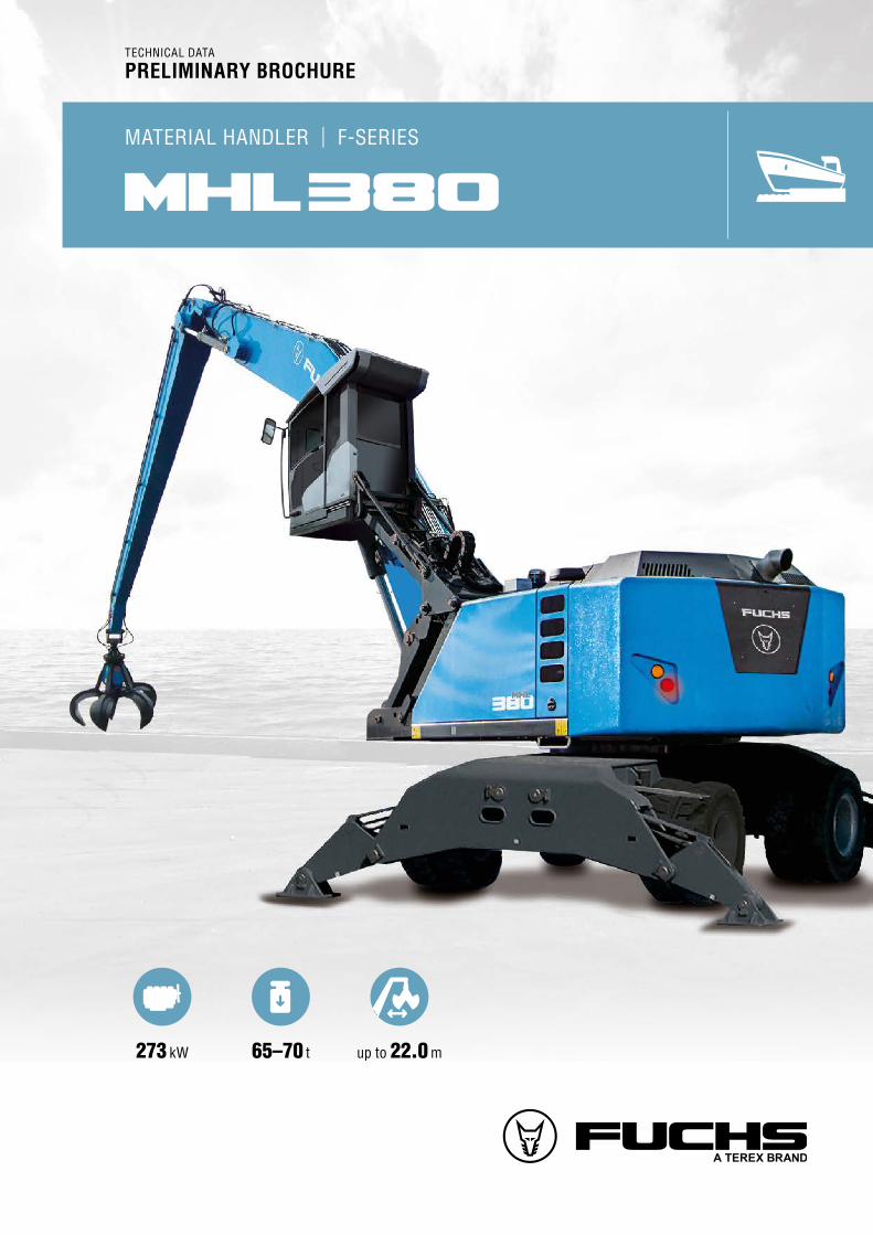
MATERIAL HANDLER | F-SERIES
mhl 380
273 kW 65–70 t up to 22.0 m
TECHNICAL DATA
PRELIMINARY BROCHURE

02
mhl380 | F-Series
EQUIPMENT AND OPTIONS. The latest technology, tailor made for you
Joystick Steering* • Improved visibility• Increased legroom and comfort
Tracked Undercarriage*• Even more stability• Less ground pressure• Flat shoes or triple grousers
Attachment Filter*• High pressure filter with monitoring • Effective protection against hydraulic oil contamination
Float Switch*• Lifts the boom automatically if too much pressure is applied• Protects sensitive surfaces like the floor of barges
Cab Floor Viewing Panel*• Improved visibility• Perfect for (un)loading barges, feeding of hoppers, etc.
Rear and Side View Cameras• Nightvision as an extra safety feature• 360° surround view system on demand
* sp
ecia
l equ
ipm
ent o
n de
man
d

03www.terex-fuchs.com
NEW CABIN
FUNCTIONALITY RE-DEFINED
Multi-function Touch Monitor
• Central operating terminal for all functions
• Large, easily legible display
• Ergonomically positioned at ideal height and distance
Downward-facing Windshield
• Improved visibility for use as a handling machine
• Additional shading from solar radiation
• Shielding effect also provides excellent visibility in the rain
Skylight
• Shape and size provide best-possible visibility in terms of usage conditions of a handling machine
• Allows as little sunlight as possible into the cab
Unique Sliding Door
• Highly convenient access through above average-sized entry hatch.
Perfect Space Utilization
• Spacious storage options and deep stowage compartments
• Thoughtful smartphone holder with charger
• Simple cleaning due to avoidance of brackets and tight corners
Spacious Refrigeration Compartment
• In characteristic fox-head shape• Provides space for drinks,
snacks, and medicines
THE NEW FUCHS CABIN. Handling of rough materials made easy and comfortable.
The design motif of the Fox Cab is the mammal from which it takes its name. The silhouette of the fox’s head is reflected subtly in the stylistic idioms. This design pro-duces an unmistakable branding effect. The aim is not only brand recognition, but also to make a connection with the machine operator: repeating, familiar elements elevate the emotional bond to the product. The Fox Cab
has been specially designed for loading machines and did not have to be subjected to any compromises as a result. This provides the user with great benefits in terms of ergonomics.

04
mhl380 | F-Series
TECHNICAL DATA
UNDERCARRIAGEFront axle Planetary drive axle with integrated drum brake,
rigidly mounted, max. steering angle: 30°
Rear axle Oscillating planetary drive rear axle with integrated drum brake and selectable oscillating axle lock
Stabilizers 4-point stabilizers
Tires Solid rubber, elastic, 8-fold, with intermediate rings
BRAKE SYSTEMService brake Hydraulic single-circuit braking system acting on all wheels
Parking brake Electrically operated disc brake on rear axle, acting on both front and rear axles via transfer gear
HYDRAULIC SYSTEMREXROTH mobile hydraulic system with load limit control and fuel-saving power-demand control, closed swing circuit. Separate oil cooler, temperature-controlled fan speed. Hose rupture valves with regeneration on the boom and stick cylinders. Hydraulic oil filter: filter elements integrated into oil tank; maintenance interval: 3,000 operating hours.
Cooling system Separated cooler with fan speed control system; optional reversing function
Max. pump capacity 640 l/min + 200 l/min in the swing circuit
Max. operating pressure 320 / 360 bar
Hydraulic oil tank 690 l
Available hydraulic oils Hydraulic oil Xtreme TempHydraulik oil Renolin B15 VG46Hydraulic oil Panolin HLP Synth. 46 bio-degradeable
OPERATOR’S CABCab Infinetely variable hydraulically height adjustable with a
max. eye level of 6.4 m (as option: independently horizon-tally adjustable by up to 2.2 m or cab riser “Port” with a max. eye level of 8.7 m and access from ground level) Sound and heat insulated panoramic windows for optimum all-round view, windshield with pull-down sunblind, visibility panel in cab roof, sliding window in cab door, sliding door.
Air-conditioning Automatic air-conditioning. Infinitely variable heating with 8-speed fan, 10 adjustable air nozzles, 3 defroster nozzles (hot water system).
Operator’s seat Air-cushioned comfort-seat with integrated headrest, safety belt and lumbar support, seat heating with integrated A/C function optional. Comfortable operation with multi-purpose adjustment options for seat position, seat inclination, seat cushion placement in relation to armrests and pilot control units.
Monitoring Ergonomic layout; glare-free instrumentation. Multi-function touch display, automatic monitoring and recording of abnormal operating conditions (including all hydraulic oil filters, hydraulic oil temperature (cold / hot) coolant temperature and charge air temperature), visual and audible warning indication with shutdown of pilot controls/ engine power reduction. Diagnosis of individual sensors available via the multi-function display. Rear view camera and side view camera.
Air conditioning Automatic AC and air conditioned stowage compartment
Acoustic power level Acoustic power level (outside) LWA 106 dB(A) (guaranteed) according to guideline 2000/14/EG LWA 107 dB(A) (valid) according to guideline 2000/14/EG Acoustic power level (inside the cabin) according to guideline ISO 6396 LPA 73 dB(A)
OFFICIAL HOMOLOGATIONCertification according to EG machinery directive 2006/42/EG
SERVICE WEIGHT WITHOUT ATTACHMENTMHL390 F 65.0 – 70.0 t
DIESEL ENGINEStage IV / EPA Tier 4 final COM III / EPA Tier III
Manufacturer and model Deutz TCD 12.0 V6 4V Deutz TCD 2015 V06 4V
Design 6-cylinder-V-engine 6-cylinder V-engine
Engine control EMR III / EMR IV EMR III
Type 4-stroke-diesel, common-rail-direct injection, turbo charger, inter-cooler, automatic exhaust aftertreatment-system with double SCR cat
4-stroke diesel, direct injection, unit pump system, turbo-charger with intercooling
Engine output 273 kW 273 kW
Nominal speed 1,800 min-1 1,800 min-1
Displacement 12.0 l 12.0 litres
Cooling system Combi-cooler (coolant / charge air) with fan speed control and reversing fan as an option
Combi-cooler (coolant / charge air) with fan speed control and re-versing fan as an option
Emission standard Stage IV / Tier 4 Final COM III / EPA Tier III
Air filter design Two stage filter with safety cartridge and pre-separator with discharge valve
Two-stage filter with safety valve
Fuel tank 822 l Diesel 822 l Diesel
DEF tank 85 l AdBlue —
ELECTRICAL SYSTEMOperating Voltage 24 V
Battery 2 × 12 V / 170 Ah / 950 A
Lights 1 × H3 spotlight on upper carriage 1 × H3 spotlight on cabin floor turn signals and rear side marker lamps
Alternator 28 V / 100 A
Option 30 kW direct current generator with insulation control, direct driven via v-belt
TRANSMISSIONHydrostatic drive through infinitely variable axial piston motor and directly mounted travel brake valves, flanged to a transfer box, all-wheel drive
Travel speed 0–8 km/h
Gradeability max. 11 %
Turning radius 9.9 m
SLEWING GEARSwing gear Internally toothed ball ring gear (double row)
Drive Two two-stage planetary gears with integrated multi-disc brake, closed circuit
Swing speed 0–6 min-1 infinitely variable
Swing lock Electrically operated
Max. pivot torque 164 kNm

www.terex-fuchs.com 05
Technical data
EQUIPMENT
CAB Standard Option
Automatic air conditioning system
Joystick steering
Steering column, height and tilt adjustable (instead of joystick steering)
Multi-function touch display
Fire extinguisher, dry powder
Radio USB & Bluetooth
Rotating beacon with travel alarm
Sliding window in cab door
Safety glass
Seat heating with integrated A/C function
Engine-independent heating
Windshield washer system
Roof washer system
12 V socket
EQUIPMENTSpotlights attached to cab floor
Spotlights mounted to superstructure
Working light stick (1×)
Load limit control
Hydraulic oil preheating
Close proximity range limiter for dipper stick
Coolant and hydraulic oil level monitoring system
Hose rupture safety valves for boom cylinders
Hose rupture safety valves for stick cylinders
Lubrication of the grab suspension by central lubrication system
LED front headlights
LED light packages
Quick-connect coupling on dipper stick
Filter system for attachments
Rear view camera
360° bird view camera system
Overload warning system basic
Overload warning and reach limitation system
Floating switch
ENGINE Standard Option
Turbo Charger
Intercooler
Direct electronic fuel injection
Advanced automatic idle incl. engine shut-off function
Engine pre-heating
Engine diagnostic interface
Temperature-controlled fan drive
UNDERCARRIAGE4-point stabilizers
4-point stabilizers, individually controllable
Stabilizer cylinders with integrated two-way check valves
All-wheel drive
Piston rod protection on stabilizer cylinders
Rear axle oscillating lock
Drum brakes
Tool box
UPPERCARRIAGEElectric diesel refuelling pump
Lighting protection
Maintenance hood with mechanical locking device
Lockable cleaning access openings on radiators
Separate cooling systems for engine and hydraulic oil cooler
Automatic central lubrication system
Reversing alarm
Special paint
Quick drain valve on Diesel tank
Quick drain valve on hydraulic oil tank
Quick drain valve on radiator
Quick drain valve on engine-oil pan
Reversing fan for coolant and hydraulic oil
CABSkylight in cab roof
Air cushioned operator’s seat with head-rest, safety belt and lumbar-support
FOPS protective guard
Front / roof protective guard
Reinforced glass (windscreen and roof panel)
Cab system vertically adjustable
Cab system horizontally and vertically adjustable
Cab system “Port”
Further optional equipment available on request!
06
2054
32324125
36006615
140
35603594371651895699
3663
140
3670
2070
2330B
A
C
3486
1883
mhl380 | F-Series
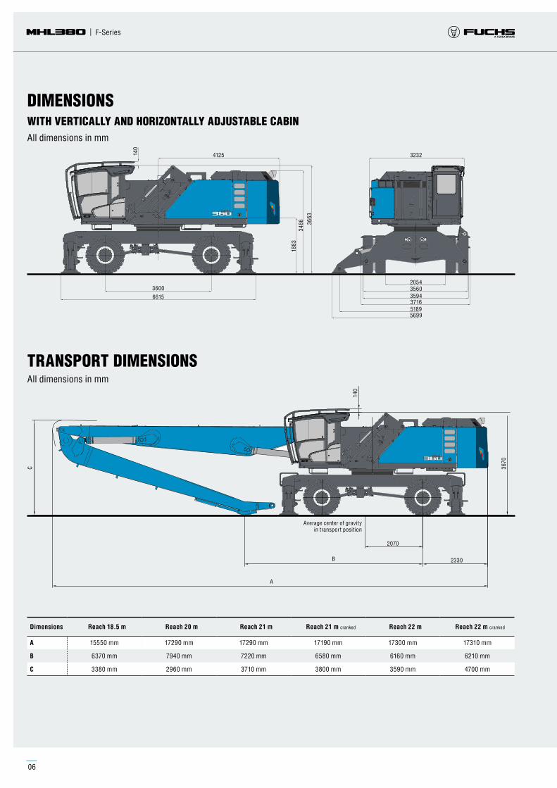
TRANSPORT DIMENSIONSAll dimensions in mm
DIMENSIONSWITH VERTICALLY AND HORIZONTALLY ADJUSTABLE CABINAll dimensions in mm
Dimensions Reach 18.5 m Reach 20 m Reach 21 m Reach 21 m cranked Reach 22 m Reach 22 m cranked
A 15550 mm 17290 mm 17290 mm 17190 mm 17300 mm 17310 mm
B 6370 mm 7940 mm 7220 mm 6580 mm 6160 mm 6210 mm
C 3380 mm 2960 mm 3710 mm 3800 mm 3590 mm 4700 mm
Average center of gravity in transport position

www.terex-fuchs.com 07
Technical data
Attachments Work equipment
Engine Options
Diesel engine Cable reel Power PackCable drumElectric motor
Undercarriage
Mobile: Standard-undercarriage
up to max. 0.8 m
up to max. 1.4 m
up to max. 0.8 m
up to max. 3.7 m
up to max. 3.7 m
Mobile special: For extended undercarriage
Crawler: Standard- undercarriage
Crawler: XL-undercarriage
Pedestal undercarriage
Pylon PylonPylon Pylon Pylon
Work equipment with cranked boom
Multi-tine grapple
Clamshell grab
Furthermore:
Timber grapple
Scrap shears
Magnet plate
Load hook
Work equipment straight
Uppercarriage MHL380
Cab system hydraulically adjustable
Viewing height: max. 6.1 m
Cab system vertically and horizontally adjustable
Viewing height: max. 6.1 m and 2.2 m
MODULAR SYSTEM

08
20 19 18 17 16 15 14 13 12 11 10 9 8 7 6 5 4 3 2 1 021222324
19
18
17
16
15
14
13
12
11
10
9
8
7
6
4
3
2
1
-9
-8
-7
-6
-5
-4
-3
-2
-1
0
20
5
21
22
23
-10
-11
mhl380 | F-Series
WORKING RANGE
The lift capacity values are stated in metric tons (t). The pump pressure is 360 bar. In accordance with ISO 10567 the lift capacity values represents 75% of the static tipping loads or 87% of the hydraulic lifting force (marked °). On solid and level ground the values apply to a swing range of 360°. The (…) values apply in the longitudinal direction of the undercarriage. The weights of the attached load hoisting equipment (grab, load hock, etc.) must be deducted from the lift capacity values. The working load of the lifting devise must be observed. In accordance with the EN 474-5 for object handling application hose rupture valves on the boom and stick cylinders, an overload warning device and the lift capacity table in the cab are required. For object handling application the machine has to be supported on a level ground.
REACH 18.5 M WITH DIPPER STICKLoading equipment Boom 9.6 m
Dipper stick 8 mMulti-tine grapple
RECOMMENDED ATTACHMENTSLift hooks 20 t
Multi-tine grapple 0.8 m3 Open or half-closed shells
Multi-tine grapple 1.0 m3 Open or half-closed shells
Multi-tine grapple 1.2 m3 Open or half-closed shells
Multi-tine grapple 1.4 m3 Open or half-closed shells
Clamshell grab 1.4 m3 Loose goods density up to 2,000 kg/m3
Clamshell grab 1.6 m3 Loose goods density up to 1,700 kg/m3
Rot
atio
n ce
nter
Reach in m
LIFTING CAPACITYReach
[m]Undercarriage
outriggerReach [m]
4.5 6 7.5 9 10.5 12 13.5 15 16.5 18
22.5 4-point supported
21 4-point supported
19.5 4-point supported
18 4-point supported 9.4° (9.4°)
16.5 4-point supported 10.1° (10.1°)
15 4-point supported 12.2° (12.2°) 10.1° (10.1°)
13.5 4-point supported 11.9° (11.9°) 11.1° (11.1°) 9.6° (9.6°)
12 4-point supported 11.8° (11.8°) 11.1° (11.1°) 10.4° (10.4°) 8.6° (8.6°)
10.5 4-point supported 12.0° (12.0°) 11.2° (11.2°) 10.5° (10.5°) 9.8 (9.9°) 6.5° (6.5°)
9 4-point supported 12.5° (12.5°) 11.5° (11.5°) 10.7° (10.7°) 9.7 (9.9°) 8.3 (8.7°)
7.5 4-point supported 14.7° (14.7°) 13.1° (13.1°) 11.9° (11.9°) 10.9° (10.9°) 9.6 (10.1°) 8.2 (9.3°)
6 4-point supported 18.7° (18.7°) 15.9° (15.9°) 13.9° (13.9°) 12.4° (12.4°) 11.2 (11.2°) 9.5 (10.3°) 8.1 (9.4°) 6.6° (6.6°)
4.5 4-point supported 39.6° (39.6°) 27.2° (27.2°) 21.0° (21.0°) 17.3° (17.3°) 14.8° (14.8°) 13.0° (13.0°) 10.9 (11.6°) 9.3 (10.4°) 8.0 (9.5°) 7.0 (7.6°)
3 4-point supported 31.3° (31.3°) 23.2° (23.2°) 18.6° (18.6°) 15.5 (15.6°) 12.7 (13.5°) 10.7 (11.9°) 9.1 (10.6°) 7.9 (9.5°) 6.9 (8.2°)
1.5 4-point supported 5.2° (5.2°) 14.6° (14.6°) 24.6 (24.6°) 18.7 (19.5°) 15.0 (16.2°) 12.3 (13.8°) 10.4 (12.0°) 9.0 (10.6°) 7.8 (9.4) 6.9 (8.1°)
0 4-point supported 5.9° (5.9°) 11.4° (11.4°) 23.7 (24.6°) 18.1 (19.9°) 14.5 (16.4°) 12.0 (13.9°) 10.2 (12.1°) 8.8 (10.5°) 7.7 (9.2°) 6.8 (7.5°)
-1.5 4-point supported 7.2° (7.2°) 11.3° (11.3°) 19.8° (19.8°) 17.7 (19.6°) 14.2 (16.2°) 11.8 (13.7°) 10.1 (11.8°) 8.7 (10.2°) 7.6 (8.7°)
-3 4-point supported 12.0° (12.0°) 18.8° (18.8°) 17.4 (18.7°) 14.0 (15.6°) 11.7 (13.2°) 10.0 (11.2°) 8.6 (9.6°) 7.6 (7.9°)
-4.5 4-point supported 19.1° (19.1°) 17.1° (17.1°) 14.0 (14.3°) 11.6 (12.1°) 9.9 (10.3°) 8.5° (8.5°)
-6 4-point supported
-7.5 4-point supported
-9 4-point supported

www.terex-fuchs.com 09
20 19 18 17 16 15 14 13 12 11 10 9 8 7 6 5 4 3 2 1 021222324
19
18
17
16
15
14
13
12
11
10
9
8
7
6
4
3
2
1
-9
-8
-7
-6
-5
-4
-3
-2
-1
0
20
5
21
22
23
-10
-11
Technical data
WORKING RANGEREACH 20 M WITH DIPPER STICKLoading equipment Boom 11.35 m
Dipper stick 8 mMulti-tine grapple
RECOMMENDED ATTACHMENTSLift hooks 20 t
Multi-tine grapple 0.8 m3 Open or half-closed shells
Multi-tine grapple 1.0 m3 Open or half-closed shells
Multi-tine grapple 1.2 m3 Open or half-closed shells
Multi-tine grapple 1.4 m3 Open or half-closed shells
Clamshell grab 1.4 m3 Loose goods density up to 2,000 kg/m3
Clamshell grab 1.6 m3 Loose goods density up to 1,700 kg/m3
Clamshell grab 2.0 m3 Loose goods density up to 1,200 kg/m3
Clamshell grab > 2.0 m3 on demand
Rot
atio
n ce
nter
Reach in m
The lift capacity values are stated in metric tons (t). The pump pressure is 360 bar. In accordance with ISO 10567 the lift capacity values represents 75% of the static tipping loads or 87% of the hydraulic lifting force (marked °). On solid and level ground the values apply to a swing range of 360°. The (…) values apply in the longitudinal direction of the undercarriage. The weights of the attached load hoisting equipment (grab, load hock, etc.) must be deducted from the lift capacity values. The working load of the lifting devise must be observed. In accordance with the EN 474-5 for object handling application hose rupture valves on the boom and stick cylinders, an overload warning device and the lift capacity table in the cab are required. For object handling application the machine has to be supported on a level ground.
LIFTING CAPACITYReach
[m]Undercarriage
outriggerReach [m]
6 7.5 9 10.5 12 13.5 15 16.5 18 19.5
22.5 4-point supported
21 4-point supported
19.5 4-point supported 10.5° (10.5°)
18 4-point supported 11.0° (11.0°) 8.6° (8.6°)
16.5 4-point supported 11.8° (11.8°) 10.8° (10.8°) 8.7° (8.7°)
15 4-point supported 11.6° (11.6°) 10.6° (10.6°) 9.8° (9.8°) 8.3° (8.3°)
13.5 4-point supported 11.6° (11.6°) 10.6° (10.6°) 9.7° (9.7°) 9.1° (9.1°) 7.3° (7.3°)
12 4-point supported 11.8° (11.8°) 10.7° (10.7°) 9.8° (9.8°) 9.1° (9.1°) 8.2 (8.4°)
10.5 4-point supported 12.1° (12.1°) 10.9° (10.9°) 10.0° (10.0°) 9.1° (9.1°) 8.2 (8.4°) 6.9 (7.8°)
9 4-point supported 14.4° (14.4°) 12.6° (12.6°) 11.3° (11.3°) 10.2° (10.2°) 9.3° (9.3°) 8.1 (8.5°) 6.9 (7.8°)
7.5 4-point supported 18.4° (18.4°) 15.4° (15.4°) 13.2° (13.2°) 11.6° (11.6°) 10.4° (10.4°) 9.3 (9.4°) 7.9 (8.6°) 6.8 (7.9°) 5.9 (6.2°)
6 4-point supported 26.6° (26.6°) 20.2° (20.2°) 16.4° (16.4°) 13.9° (13.9°) 12.1° (12.1°) 10.7 (10.7°) 9.1 (9.6°) 7.8 (8.7°) 6.7 (7.9°) 5.9 (7.1°)
4.5 4-point supported 15.6° (15.6°) 21.9° (21.9°) 17.4° (17.4°) 14.5° (14.5°) 12.3 (12.5°) 10.3 (10.9°) 8.8 (9.7°) 7.6 (8.7°) 6.6 (7.9°) 5.8 (7.0°)
3 4-point supported 5.7° (5.7°) 19.3° (19.3°) 17.9 (18.1°) 14.3 (15.0°) 11.8 (12.8°) 10.0 (11.1°) 8.6 (9.8°) 7.4 (8.8°) 6.5 (7.8°) 5.7 (6.9°)
1.5 4-point supported 4.8° (4.8°) 11.9° (11.9°) 17.0 (18.4°) 13.7 (15.2°) 11.4 (12.9°) 9.7 (11.2°) 8.3 (9.8°) 7.3 (8.7°) 6.4 (7.7°) 5.7 (6.7°)
0 4-point supported 5.6° (5.6°) 10.5° (10.5°) 16.4 (18.1°) 13.3 (15.1°) 11.1 (12.8°) 9.4 (11.1°) 8.2 (9.7°) 7.1 (8.5°) 6.3 (7.5°) 5.7 (6.3°)
-1.5 4-point supported 6.8° (6.8°) 10.6° (10.6°) 16.1 (17.4°) 13.0 (14.6°) 10.8 (12.5°) 9.3 (10.8°) 8.0 (9.4°) 7.1 (8.2°) 6.3 (7.1°) 5.6 (5.7°)
-3 4-point supported 11.4° (11.4°) 16.0 (16.1°) 12.8 (13.8°) 10.7 (11.8°) 9.1 (10.2°) 7.9 (8.9°) 7.0 (7.7°) 6.3 (6.4°)
-4.5 4-point supported 14.5° (14.5°) 12.5° (12.5°) 10.7 (10.9°) 9.1 (9.4°) 7.9 (8.1°) 6.9° (6.9°)
-6 4-point supported 9.5° (9.5°) 8.2° (8.2°)
-7.5 4-point supported
-9 4-point supported

10
20 19 18 17 16 15 14 13 12 11 10 9 8 7 6 5 4 3 2 1 0212223242526
19
18
17
16
15
14
13
12
11
10
9
8
7
6
4
3
2
1
-9
-8
-7
-6
-5
-4
-3
-2
-1
0
20
5
21
22
23
24
-10
-11
-12
-13
-14
mhl380 | F-Series
WORKING RANGE
The lift capacity values are stated in metric tons (t). The pump pressure is 360 bar. In accordance with ISO 10567 the lift capacity values represents 75% of the static tipping loads or 87% of the hydraulic lifting force (marked °). On solid and level ground the values apply to a swing range of 360°. The (…) values apply in the longitudinal direction of the undercarriage. The weights of the attached load hoisting equipment (grab, load hock, etc.) must be deducted from the lift capacity values. The working load of the lifting devise must be observed. In accordance with the EN 474-5 for object handling application hose rupture valves on the boom and stick cylinders, an overload warning device and the lift capacity table in the cab are required. For object handling application the machine has to be supported on a level ground.
REACH 21 M WITH DIPPER STICKLoading equipment Boom 11.35 m
Dipper stick 8.94 mMulti-tine grapple
RECOMMENDED ATTACHMENTSLift hooks 20 t
Multi-tine grapple 0.8 m3 Open or half-closed shells
Multi-tine grapple 1.0 m3 Open or half-closed shells
Multi-tine grapple 1.2 m3 Open or half-closed shells
Multi-tine grapple 1.4 m3 Open or half-closed shells
Clamshell grab 1.4 m3 Loose goods density up to 2,000 kg/m3
Clamshell grab 1.6 m3 Loose goods density up to 1,700 kg/m3
Clamshell grab 2.0 m3 Loose goods density up to 1,200 kg/m3
Clamshell grab > 2.0 m3 on demand
Rot
atio
n ce
nter
Reach in m
LIFTING CAPACITYReach
[m]Undercarriage
outriggerReach [m]
4.5 6 7.5 9 10.5 12 13.5 15 16.5 18 19.5 21
22.5 4-point supported
21 4-point supported 8.2° (8.2°)
19.5 4-point supported 9.1° (9.1°)
18 4-point supported 10.8° (10.8°) 9.3° (9.3°) 7.1° (7.1°)
16.5 4-point supported 10.1° (10.1°) 9.3° (9.3°) 7.0° (7.0°)
15 4-point supported 9.9° (9.9°) 9.2° (9.2°) 8.6° (8.6°) 6.3° (6.3°)
13.5 4-point supported 9.9° (9.9°) 9.2° (9.2°) 8.6° (8.6°) 8.1° (8.1°)
12 4-point supported 10.1° (10.1°) 9.3° (9.3°) 8.6° (8.6°) 8.1° (8.1°) 7.1 (7.2°)
10.5 4-point supported 11.4° (11.4°) 10.3° (10.3°) 9.5° (9.5°) 8.7° (8.7°) 8.1° (8.1°) 7.1 (7.5°) 5.0° (5.0°)
9 4-point supported 11.9° (11.9°) 10.7° (10.7°) 9.7° (9.7°) 8.9° (8.9°) 8.2° (8.2°) 7.0 (7.6°) 6.0 (6.7°)
7.5 4-point supported 14.4° (14.4°) 12.5° (12.5°) 11.1° (11.1°) 10.0° (10.0°) 9.1° (9.1°) 8.0 (8.3°) 6.9 (7.6°) 6.0 (7.0°)
6 4-point supported 23.8° (23.8°) 18.8° (18.8°) 15.5° (15.5°) 13.2° (13.2°) 11.6° (11.6°) 10.3° (10.3°) 9.2 (9.3°) 7.9 (8.4°) 6.8 (7.7°) 5.9 (7.0°)
4.5 4-point supported 27.8° (27.8°) 20.7° (20.7°) 16.6° (16.6°) 14.0° (14.0°) 12.0° (12.0°) 10.5 (10.6°) 8.9 (9.5°) 7.7 (8.5°) 6.7 (7.7°) 5.8 (7.0°)
3 4-point supported 10.8° (10.8°) 22.3° (22.3°) 17.6° (17.6°) 14.6° (14.6°) 12.1 (12.4°) 10.1 (10.9°) 8.7 (9.6°) 7.5 (8.6°) 6.5 (7.7°) 5.7 (6.9°) 5.1° (5.3°)
1.5 4-point supported 6.5° (6.5°) 16.2° (16.2°) 17.5 (18.2°) 14.0 (15.0°) 11.6 (12.7°) 9.8 (11.0°) 8.4 (9.7°) 7.3 (8.6°) 6.4 (7.7°) 5.7 (6.8°)
0 4-point supported 3.2° (3.2°) 6.2° (6.2°) 12.0° (12.0°) 16.7 (18.3°) 13.5 (15.1°) 11.2 (12.8°) 9.5 (11.0°) 8.2 (9.7°) 7.1 (8.5°) 6.3 (7.5°) 5.6 (6.6°)
-1.5 4-point supported 6.8° (6.8°) 11.1° (11.1°) 16.3 (17.9°) 13.1 (14.9°) 10.9 (12.6°) 9.3 (10.9°) 8.0 (9.5°) 7.0 (8.3°) 6.2 (7.3°) 5.6 (6.2°)
-3 4-point supported 7.8° (7.8°) 11.2° (11.2°) 16.0 (17.0°) 12.9 (14.3°) 10.7 (12.2°) 9.1 (10.5°) 7.9 (9.1°) 6.9 (7.9°) 6.2 (6.8°) 5.5 (5.6°)
-4.5 4-point supported 11.8° (11.8°) 15.6° (15.6°) 12.8 (13.3°) 10.6 (11.4°) 9.0 (9.9°) 7.8 (8.5°) 6.9 (7.3°) 6.1° (6.1°)
-6 4-point supported 13.8° (13.8°) 12.0° (12.0°) 10.3° (10.3°) 8.9° (8.9°) 7.7° (7.7°) 6.4° (6.4°)
-7.5 4-point supported
-9 4-point supported

www.terex-fuchs.com 11
20 19 18 17 16 15 14 13 12 11 10 9 8 7 6 5 4 3 2 1 0212223242526
19
18
17
16
15
14
13
12
11
10
9
8
7
6
4
3
2
1
-9
-8
-7
-6
-5
-4
-3
-2
-1
0
20
5
21
22
23
24
-10
-11
-12
-13
-14
Technical data
WORKING RANGEREACH 21 M CRANKED BOOMLoading equipment Cranked Boom 11.35 m
Dipper stick 8.94 mMulti-tine grapple
RECOMMENDED ATTACHMENTSLift hooks 20 t
Multi-tine grapple 0.8 m3 Open or half-closed shells
Multi-tine grapple 1.0 m3 Open or half-closed shells
Multi-tine grapple 1.2 m3 Open or half-closed shells
Multi-tine grapple 1.4 m3 Open or half-closed shells
Clamshell grab 1.4 m3 Loose goods density up to 2,000 kg/m3
Clamshell grab 1.6 m3 Loose goods density up to 1,700 kg/m3
Clamshell grab 2.0 m3 Loose goods density up to 1,200 kg/m3
Clamshell grab > 2.0 m3 on demand
Rot
atio
n ce
nter
Reach in m
The lift capacity values are stated in metric tons (t). The pump pressure is 360 bar. In accordance with ISO 10567 the lift capacity values represents 75% of the static tipping loads or 87% of the hydraulic lifting force (marked °). On solid and level ground the values apply to a swing range of 360°. The (…) values apply in the longitudinal direction of the undercarriage. The weights of the attached load hoisting equipment (grab, load hock, etc.) must be deducted from the lift capacity values. The working load of the lifting devise must be observed. In accordance with the EN 474-5 for object handling application hose rupture valves on the boom and stick cylinders, an overload warning device and the lift capacity table in the cab are required. For object handling application the machine has to be supported on a level ground.
LIFTING CAPACITYReach
[m]Undercarriage
outrigger 4.5
Reach [m]
6 7.5 9 10.5 12 13.5 15 16.5 18 19.5
22.5 4-point supported
21 4-point supported
19.5 4-point supported
18 4-point supported 8.3° (8.3°) 6.0° (6.0°)
16.5 4-point supported 7.8° (7.8°) 5.9° (5.9°)
15 4-point supported 7.7° (7.7°) 7.4° (7.4°) 5.3° (5.3°)
13.5 4-point supported 7.7° (7.7°) 7.3° (7.3°) 7.0° (7.0°)
12 4-point supported 7.7° (7.7°) 7.3° (7.3°) 7.0° (7.0°) 6.2° (6.2°)
10.5 4-point supported 7.9° (7.9°) 7.5° (7.5°) 7.1° (7.1°) 6.7° (6.7°)
9 4-point supported 8.9° (8.9°) 8.2° (8.2°) 7.7° (7.7°) 7.2° (7.2°) 6.8° (6.8°) 5.8° (5.8°)
7.5 4-point supported 10.4° (10.4°) 9.4° (9.4°) 8.6° (8.6°) 7.9° (7.9°) 7.4° (7.4°) 6.9 (6.9°) 5.9 (6.5°)
6 4-point supported 13.0° (13.0°) 11.3° (11.3°) 10.0° (10.0°) 9.0° (9.0°) 8.2° (8.2°) 7.6° (7.6°) 6.7 (7.0°) 5.9 (6.6°)
4.5 4-point supported 23.9° (23.9°) 17.9° (17.9°) 14.4° (14.4°) 12.2° (12.2°) 10.6° (10.6°) 9.4° (9.4°) 8.5° (8.5°) 7.6 (7.8°) 6.6 (7.2°) 5.8 (6.6°)
3 4-point supported 13.1° (13.1°) 20.0° (20.0°) 15.7° (15.7°) 13.0° (13.0°) 11.2° (11.2°) 9.8° (9.8°) 8.6 (8.8°) 7.4 (8.0°) 6.5 (7.3°) 5.7 (6.7°)
1.5 4-point supported 7.8° (7.8°) 18.0° (18.0°) 16.7° (16.7°) 13.7° (13.7°) 11.5 (11.7°) 9.7 (10.2°) 8.3 (9.0°) 7.2 (8.1°) 6.3 (7.4°) 5.6 (6.7°)
0 4-point supported 4.1° (4.1°) 7.2° (7.2°) 13.1° (13.1°) 16.6 (17.3°) 13.4 (14.2°) 11.1 (12.0°) 9.4 (10.4°) 8.1 (9.2°) 7.1 (8.2°) 6.2 (7.4°) 5.5 (6.6°)
-1.5 4-point supported 5.3° (5.3°) 7.6° (7.6°) 11.9° (11.9°) 16.1 (17.5°) 13.0 (14.4°) 10.8 (12.2°) 9.2 (10.6°) 7.9 (9.3°) 6.9 (8.2°) 6.1 (7.3°) 5.5 (6.5°)
-3 4-point supported 6.4° (6.4°) 8.3° (8.3°) 11.8° (11.8°) 15.8 (17.3°) 12.7 (14.4°) 10.6 (12.2°) 9.0 (10.5°) 7.8 (9.2°) 6.9 (8.1°) 6.1 (7.1°) 5.5 (6.2°)
-4.5 4-point supported 9.1° (9.1°) 12.2° (12.2°) 15.7 (16.7°) 12.6 (14.0°) 10.5 (11.9°) 8.9 (10.3°) 7.7 (9.0°) 6.8 (7.8°) 6.1 (6.8°)
-6 4-point supported 12.8° (12.8°) 15.7° (15.7°) 12.6 (13.2°) 10.5 (11.3°) 8.9 (9.8°) 7.7 (8.5°) 6.8 (7.3°) 6.1 (6.1°)
-7.5 4-point supported 14.2° (14.2°) 12.1° (12.1°) 10.4° (10.4°) 9.0 (9.0°) 7.7° (7.7°) 6.5° (6.5°)
-9 4-point supported

12
20 19 18 17 16 15 14 13 12 11 10 9 8 7 6 5 4 3 2 1 0212223242526
19
18
17
16
15
14
13
12
11
10
9
8
7
6
4
3
2
1
-9
-8
-7
-6
-5
-4
-3
-2
-1
0
20
5
21
22
23
24
-10
-11
-12
-13
-14
mhl380 | F-Series
WORKING RANGE
The lift capacity values are stated in metric tons (t). The pump pressure is 360 bar. In accordance with ISO 10567 the lift capacity values represents 75% of the static tipping loads or 87% of the hydraulic lifting force (marked °). On solid and level ground the values apply to a swing range of 360°. The (…) values apply in the longitudinal direction of the undercarriage. The weights of the attached load hoisting equipment (grab, load hock, etc.) must be deducted from the lift capacity values. The working load of the lifting devise must be observed. In accordance with the EN 474-5 for object handling application hose rupture valves on the boom and stick cylinders, an overload warning device and the lift capacity table in the cab are required. For object handling application the machine has to be supported on a level ground.
REACH 22 M WITH DIPPER STICKLoading equipment Boom 11.35 m
Dipper stick 9.9 mMulti-tine grapple
RECOMMENDED ATTACHMENTSLift hooks 20 t
Multi-tine grapple 0.8 m3 Open or half-closed shells
Multi-tine grapple 1.0 m3 Open or half-closed shells
Multi-tine grapple 1.2 m3 Open or half-closed shells
Multi-tine grapple 1.4 m3 Open or half-closed shells
Clamshell grab 1.4 m3 Loose goods density up to 2,000 kg/m3
Clamshell grab 1.6 m3 Loose goods density up to 1,700 kg/m3
Clamshell grab 2.0 m3 Loose goods density up to 1,200 kg/m3
Clamshell grab > 2.0 m3 on demand
Rot
atio
n ce
nter
Reach in m
LIFTING CAPACITYReach
[m]Undercarriage
outriggerReach [m]
4.5 6 7.5 9 10.5 12 13.5 15 16.5 18 19.5 21
22.5 4-point supported
21 4-point supported 7.3° (7.3°)
19.5 4-point supported 7.8° (7.8°)
18 4-point supported 9.4° (9.4°) 7.9° (7.9°) 5.7° (5.7°)
16.5 4-point supported 9.7° (9.7°) 9.0° (9.0°) 7.8° (7.8°) 5.4° (5.4°)
15 4-point supported 9.6° (9.6°) 8.9° (8.9°) 8.4° (8.4°) 7.3° (7.3°)
13.5 4-point supported 9.6° (9.6°) 8.9° (8.9°) 8.3° (8.3°) 7.8° (7.8°) 6.5° (6.5°)
12 4-point supported 9.7° (9.7°) 9.0° (9.0°) 8.4° (8.4°) 7.8° (7.8°) 7.3 (7.3°) 5.1° (5.1°)
10.5 4-point supported 10.0° (10.0°) 9.2° (9.2°) 8.5° (8.5°) 7.9° (7.9°) 7.3 (7.4°) 6.2 (6.6°)
9 4-point supported 11.4° (11.4°) 10.3° (10.3°) 9.4° (9.4°) 8.6° (8.6°) 8.0° (8.0°) 7.2 (7.4°) 6.2 (6.9°)
7.5 4-point supported 12.0° (12.0°) 10.7° (10.7°) 9.7° (9.7°) 8.8° (8.8°) 8.1° (8.1°) 7.1 (7.5°) 6.1 (6.9°) 5.3 (5.5°)
6 4-point supported 17.5° (17.5°) 14.7° (14.7°) 12.7° (12.7°) 11.2° (11.2°) 10.0° (10.0°) 9.0° (9.0°) 8.0 (8.2°) 6.9 (7.6°) 6.0 (6.9°) 5.3 (6.3°)
4.5 4-point supported 37.1° (37.1°) 25.3° (25.3°) 19.4° (19.4°) 15.8° (15.8°) 13.4° (13.4°) 11.6° (11.6°) 10.3° (10.3°) 9.1 (9.2°) 7.8 (8.4°) 6.8 (7.6°) 5.9 (6.9°) 5.2 (6.3°)
3 4-point supported 28.5° (28.5°) 21.1° (21.1°) 16.8° (16.8°) 14.0° (14.0°) 12.0° (12.0°) 10.3 (10.6°) 8.8 (9.4°) 7.6 (8.5°) 6.6 (7.6°) 5.8 (6.9°) 5.1 (6.2°)
1.5 4-point supported 4.1° (4.1°) 10.5° (10.5°) 22.2° (22.2°) 17.5° (17.5°) 14.2 (14.5°) 11.8 (12.3°) 9.9 (10.8°) 8.5 (9.5°) 7.4 (8.5°) 6.4 (7.6°) 5.7 (6.8°) 5.1 (6.1°)
0 4-point supported 4.4° (4.4°) 8.0° (8.0°) 15.7° (15.7°) 16.8 (17.8°) 13.5 (14.7°) 11.2 (12.5°) 9.5 (10.8°) 8.2 (9.5°) 7.2 (8.5°) 6.3 (7.5°) 5.6 (6.7°) 5.0 (5.8°)
-1.5 4-point supported 5.2° (5.2°) 7.8° (7.8°) 12.8° (12.8°) 16.1 (17.7°) 13.0 (14.6°) 10.8 (12.4°) 9.2 (10.7°) 8.0 (9.4°) 7.0 (8.3°) 6.2 (7.4°) 5.5 (6.4°) 5.0 (5.4°)
-3 4-point supported 6.1° (6.1°) 8.2° (8.2°) 12.1° (12.1°) 15.7 (17.0°) 12.6 (14.2°) 10.6 (12.1°) 9.0 (10.5°) 7.8 (9.2°) 6.9 (8.0°) 6.1 (7.0°) 5.5° (5.5°)
-4.5 4-point supported 8.9° (8.9°) 12.1° (12.1°) 15.4 (16.0°) 12.4 (13.5°) 10.4 (11.5°) 8.9 (10.0°) 7.7 (8.7°) 6.8 (7.6°) 6.0 (6.5°) 5.4° (5.4°)
-6 4-point supported 12.6° (12.6°) 14.5° (14.5°) 12.4 (12.4°) 10.3 (10.7°) 8.8 (9.2°) 7.6 (8.0°) 6.8 (6.9°) 5.8° (5.8°)
-7.5 4-point supported 10.9° (10.9°) 9.4° (9.4°) 8.2° (8.2°) 7.0° (7.0°)
-9 4-point supported

www.terex-fuchs.com 13
20 19 18 17 16 15 14 13 12 11 10 9 8 7 6 5 4 3 2 1 0212223242526
19
18
17
16
15
14
13
12
11
10
9
8
7
6
4
3
2
1
-9
-8
-7
-6
-5
-4
-3
-2
-1
0
20
5
21
22
23
24
-10
-11
-12
-13
-14
Technical data
WORKING RANGEREACH 22 M CRANKED BOOMLoading equipment Boom 11.35 m
Dipper stick 9.9 mMulti-tine grapple
RECOMMENDED ATTACHMENTSLift hooks 20 t
Multi-tine grapple 0.8 m3 Open or half-closed shells
Multi-tine grapple 1.0 m3 Open or half-closed shells
Multi-tine grapple 1.2 m3 Open or half-closed shells
Multi-tine grapple 1.4 m3 Open or half-closed shells
Clamshell grab 1.4 m3 Loose goods density up to 2,000 kg/m3
Clamshell grab 1.6 m3 Loose goods density up to 1,700 kg/m3
Clamshell grab 2.0 m3 Loose goods density up to 1,200 kg/m3
Clamshell grab > 2.0 m3 on demand
Rot
atio
n ce
nter
Reach in m
The lift capacity values are stated in metric tons (t). The pump pressure is 360 bar. In accordance with ISO 10567 the lift capacity values represents 75% of the static tipping loads or 87% of the hydraulic lifting force (marked °). On solid and level ground the values apply to a swing range of 360°. The (…) values apply in the longitudinal direction of the undercarriage. The weights of the attached load hoisting equipment (grab, load hock, etc.) must be deducted from the lift capacity values. The working load of the lifting devise must be observed. In accordance with the EN 474-5 for object handling application hose rupture valves on the boom and stick cylinders, an overload warning device and the lift capacity table in the cab are required. For object handling application the machine has to be supported on a level ground.
LIFTING CAPACITYReach
[m]Undercarriage
outriggerReach [m]
3 4.5 6 7.5 9 10.5 12 13.5 15 16.5 18 19.5 21
22.5 4-point supported
21 4-point supported
19.5 4-point supported
18 4-point supported 7.1° (7.1°)
16.5 4-point supported 7.5° (7.5°) 6.9° (6.9°)
15 4-point supported 7.1° (7.1°) 6.5° (6.5°)
13.5 4-point supported 7.1° (7.1°) 6.8° (6.8°) 5.7° (5.7°)
12 4-point supported 7.1° (7.1°) 6.8° (6.8°) 6.5° (6.5°)
10.5 4-point supported 7.7° (7.7°) 7.2° (7.2°) 6.9° (6.9°) 6.6° (6.6°) 5.8° (5.8°)
9 4-point supported 7.9° (7.9°) 7.4° (7.4°) 7.0° (7.0°) 6.6° (6.6°) 6.2 (6.3°)
7.5 4-point supported 9.0° (9.0°) 8.3° (8.3°) 7.7° (7.7°) 7.2° (7.2°) 6.7° (6.7°) 6.1 (6.4°) 4.6° (4.6°)
6 4-point supported 10.7° (10.7°) 9.6° (9.6°) 8.7° (8.7°) 8.0° (8.0°) 7.4° (7.4°) 6.9° (6.9°) 6.0 (6.5°) 5.3 (5.4°)
4.5 4-point supported 16.4° (16.4°) 13.5° (13.5°) 11.6° (11.6°) 10.2° (10.2°) 9.1° (9.1°) 8.3° (8.3°) 7.6° (7.6°) 6.8 (7.0°) 5.9 (6.5°) 5.2 (6.1°)
3 4-point supported 9.6° (9.6°) 25.1° (25.1°) 18.5° (18.5°) 14.8° (14.8°) 12.4° (12.4°) 10.7° (10.7°) 9.5° (9.5°) 8.6° (8.6°) 7.6 (7.8°) 6.6 (7.2°) 5.8 (6.6°) 5.1 (6.1°)
1.5 4-point supported 5.2° (5.2°) 12.1° (12.1°) 20.2° (20.2°) 15.9° (15.9°) 13.2° (13.2°) 11.3° (11.3°) 9.9° (9.9°) 8.5 (8.8°) 7.4 (8.0°) 6.5 (7.3°) 5.7 (6.7°) 5.1 (6.1°)
0 4-point supported 3.5° (3.5°) 5.2° (5.2°) 9.1° (9.1°) 17.0° (17.0°) 16.7° (16.7°) 13.6 (13.7°) 11.3 (11.7°) 9.6 (10.2°) 8.2 (9.0°) 7.2 (8.1°) 6.3 (7.3°) 5.6 (6.7°) 5.0 (6.0°)
-1.5 4-point supported 4.6° (4.6°) 5.9° (5.9°) 8.6° (8.6°) 13.7° (13.7°) 16.1 (17.1°) 13.0 (14.1°) 10.9 (11.9°) 9.2 (10.4°) 8.0 (9.1°) 7.0 (8.2°) 6.2 (7.3°) 5.5 (6.6°) 5.0 (5.6°)
-3 4-point supported 6.7° (6.7°) 8.8° (8.8°) 12.7° (12.7°) 15.6 (17.1°) 12.6 (14.1°) 10.6 (12.0°) 9.0 (10.4°) 7.8 (9.2°) 6.9 (8.1°) 6.1 (7.3°) 5.5 (6.4°)
-4.5 4-point supported 7.4° (7.4°) 9.3° (9.3°) 12.5° (12.5°) 15.4 (16.7°) 12.4 (13.9°) 10.4 (11.9°) 8.9 (10.3°) 7.7 (9.0°) 6.8 (8.0°) 6.0 (7.0°) 5.5 (6.1°)
-6 4-point supported 9.9° (9.9°) 12.7° (12.7°) 15.4 (16.0°) 12.3 (13.4°) 10.3 (11.5°) 8.8 (9.9°) 7.6 (8.7°) 6.8 (7.6°) 6.0 (6.6°)
-7.5 4-point supported 13.2° (13.2°) 14.8° (14.8°) 12.4 (12.6°) 10.3 (10.8°) 8.8 (9.4°) 7.7 (8.1°) 6.8 (7.0°) 5.9° (5.9°)
-9 4-point supported 13.2° (13.2°) 11.3° (11.3°) 9.8° (9.8°) 8.4° (8.4°) 7.2° (7.2°)

mhl380 | F-Series
NOTES

www.terex-fuchs.com
www.terex-fuchs.comNovember 2016. Product specifications and prices are subject to change without notice or obligation. The photographs and/or drawings in this document are for illustrative purposes only. Refer to the appropriate Operator’s Manual for instructions on the proper use of this equipment. Failure to follow the appropriate Operator’s Manual when using our equipment or to otherwise act irresponsibly may result in serious injury or death. The only warranty applicable to our equipment is the standard written warranty applicable to the particular product and sale and Terex makes no other warranty, express or implied. © Terex Corporation 2016 · Terex, the Terex Crown design, Fuchs and Works For You are trademarks of Terex Corporation or its subsidiaries.
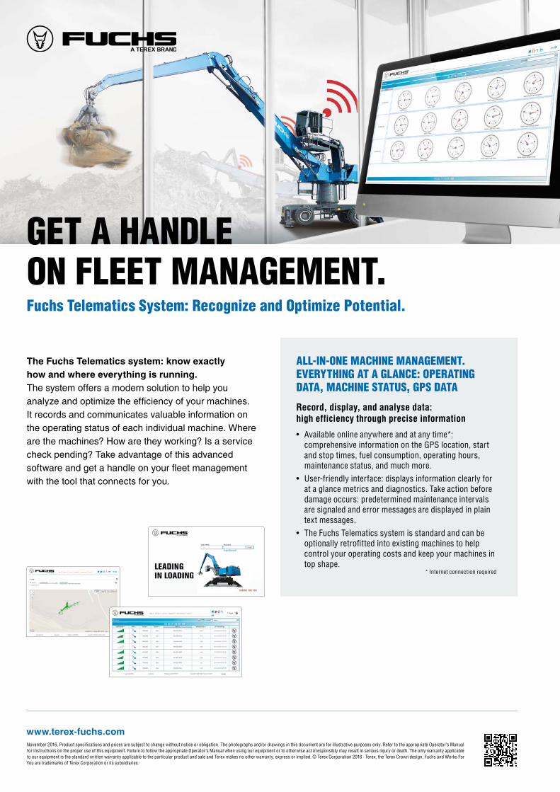
GET A HANDLE ON FLEET MANAGEMENT. Fuchs Telematics System: Recognize and Optimize Potential.
ALL-IN-ONE MACHINE MANAGEMENT. EVERYTHING AT A GLANCE: OPERATING DATA, MACHINE STATUS, GPS DATA
Record, display, and analyse data: high efficiency through precise information
• Available online anywhere and at any time*: comprehensive information on the GPS location, start and stop times, fuel consumption, operating hours, maintenance status, and much more.
• User-friendly interface: displays information clearly for at a glance metrics and diagnostics. Take action before damage occurs: predetermined maintenance intervals are signaled and error messages are displayed in plain text messages.
• The Fuchs Telematics system is standard and can be optionally retrofitted into existing machines to help control your operating costs and keep your machines in top shape.
* Internet connection required
The Fuchs Telematics system: know exactly how and where everything is running. The system offers a modern solution to help you analyze and optimize the efficiency of your machines. It records and communicates valuable information on the operating status of each individual machine. Where are the machines? How are they working? Is a service check pending? Take advantage of this advanced software and get a handle on your fleet management with the tool that connects for you.