mg section 1 hw
DESCRIPTION
dddTRANSCRIPT

9.3.1. Motors use the effect of, forces on current-carrying conductors in magnetic fields.
1.1.2 Describe qualitatively and quantitatively the force between long, parallel
current-carrying conductors using:
1 Two long, parallel, current-carrying conductors attract each other with a force of F Newtons. The current in each, and the distance between them is tripled. Predict the new force between the wires.2 Two long, parallel current-carrying conductors are separated by d metres. If all other variables are kept constant:(a) Sketch a graph to show the relationship between the force between the wires and their separation, d.
(b) Sketch a graph to show the relationship between the force between the wires and the current in one of the wires.3 Forces between parallel conductors.
(a) Explain the difference between the force between parallel conductors and the force per unit length between parallel conductors.
(b) If a pair of parallel conductors was 0.25 m long, predict the ratio of the force between them to the force per unit length between them.
1.1.1 Discuss the effect, on the magnitude of the force on a current-carrying conductor, of variations in:
• the strength of the magnetic field in which it is located• the magnitude of the current in the conductor• the length of the conductor in the magnetic field• the angle between the direction of the external magnetic field and the direction of the length of the conductor.
1 A current-carrying conductor is at an angle of 30' to a magnetic field. It experiences a force of F newtons. Predict the new force on the conductor if.
(a) the magnetic field is doubled in strength (b) the current flowing in the conductor is halved (c) the length of the conductor in the field is halved (d) the angle the conductor makes with the field is increased to 60 .
2 Predict the effect on the force on the conductor in Q1 if all four changes are made at the same time.

1.2.1 Solve problems using:
1 Two parallel conductors are 0.3 m long, and 0. 15 m apart. They each carry 2.5 A of current in the same direction.(a) Calculate the force between them.(b) Calculate the force per unit length between them.(c) Predict the force between the wires if each current was doubled, the distance between them doubled, and one of the current directions was reversed.2. Calculate the force per unit of length between 2 long, parallel wires carrying 15.3A and 12.7A and separated by 1.00cm. State the direction of the force, given that the currents are in opposite directions.3. Two long, parallel wires are carrying equal currents. The wires are 10.0cm
apart. The force between them is found to be 8.25x10⁻⁵ N per metre of length, attracting each other.
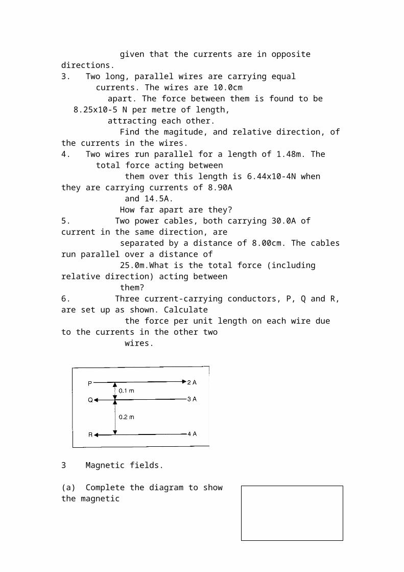
Find the magitude, and relative direction, of the currents in the wires.4. Two wires run parallel for a length of 1.48m. The total force acting between them over this length is 6.44x10⁻⁴N when they are carrying currents of 8.90A and 14.5A. How far apart are they?5. Two power cables, both carrying 30.0A of current in the same direction, are separated by a distance of 8.00cm. The cables run parallel over a distance of 25.0m.What is the total force (including relative direction) acting between them?6. Three current-carrying conductors, P, Q and R, are set up as shown. Calculate the force per unit length on each wire due to the currents in the other two wires.
3 Magnetic fields.
(a) Complete the diagram to show the magnetic fields due to the current in each of the wires.
(b) Explain in terms of these magnetic fields the force between the two wires.
1.2.3 Solve problems and analyse information about the force on current-carrying conductors in magnetic fields using: F= BIl sin Φ
1.A wire is carrying 4.50A of current through a 11.0T field, directed as shown. The length of wire in the field is 1.25m.Find the magnitude and direction of the force on thewire.
2. Find the magnitude & direction of the force which would act on the wire shown. The length of wire within the field is 0.385m.
3. The vertical wire runs for 2.44m through a 105T field directed out of the page. The force on the wire is 27.2N left.Find the magnitude and direction of the current in the wire.
4. A wire is carrying 8.00A of current over a length of 0.287m through a magnetic field of 7.50T. A force of 3.72N acts on the wire.Find the angle between the wire and the field lines.
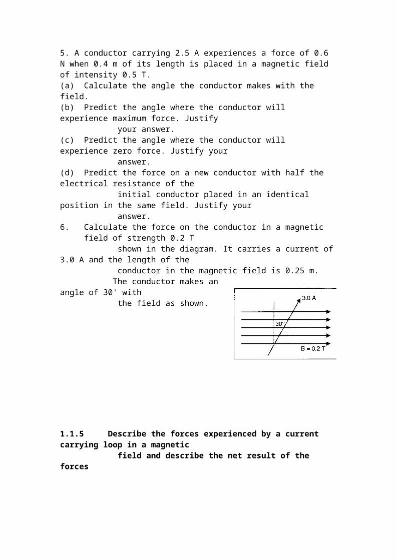
5. A conductor carrying 2.5 A experiences a force of 0.6 N when 0.4 m of its length is placed in a magnetic field of intensity 0.5 T.(a) Calculate the angle the conductor makes with the field.(b) Predict the angle where the conductor will experience maximum force. Justify your answer.(c) Predict the angle where the conductor will experience zero force. Justify your answer.(d) Predict the force on a new conductor with half the electrical resistance of the initial conductor placed in an identical position in the same field. Justify your answer.6. Calculate the force on the conductor in a magnetic field of strength 0.2 T shown in the diagram. It carries a current of 3.0 A and the length of the conductor in the magnetic field is 0.25 m. The conductor makes an angle of 30' with the field as shown.

1.1.5 Describe the forces experienced by a current carrying loop in a magnetic field and describe the net result of the forces
1 The diagram shows a circular, current-carrying loop of wire in a magnetic
field.
(a) Draw vectors to show the direction of the forces acting on the wire.(b) Determine the resultant force on the loop.
2 The diagram shows a horizontal, 10 cm square loop carrying 1. 5 A in a magnetic field of strength 0.25 T.
(a) Describe and label the force acting on each side of the coil. Justify each answer. Side AB Side BD Side CD Side AC (b) If the coil was pivoted through the middle of sides AB/CD, predict what would happen to it.(c) Predict the force on side AC of the loop if it was made into a coil with 50 turns.(d) Predict the force on side AC of the loop the strength if the magnetic field was halved.(e) Predict the force on side AC of the loop if the current flowing in it was doubled.
1.2.2. Perform a first-hand investigation to demonstrate the motor effect.
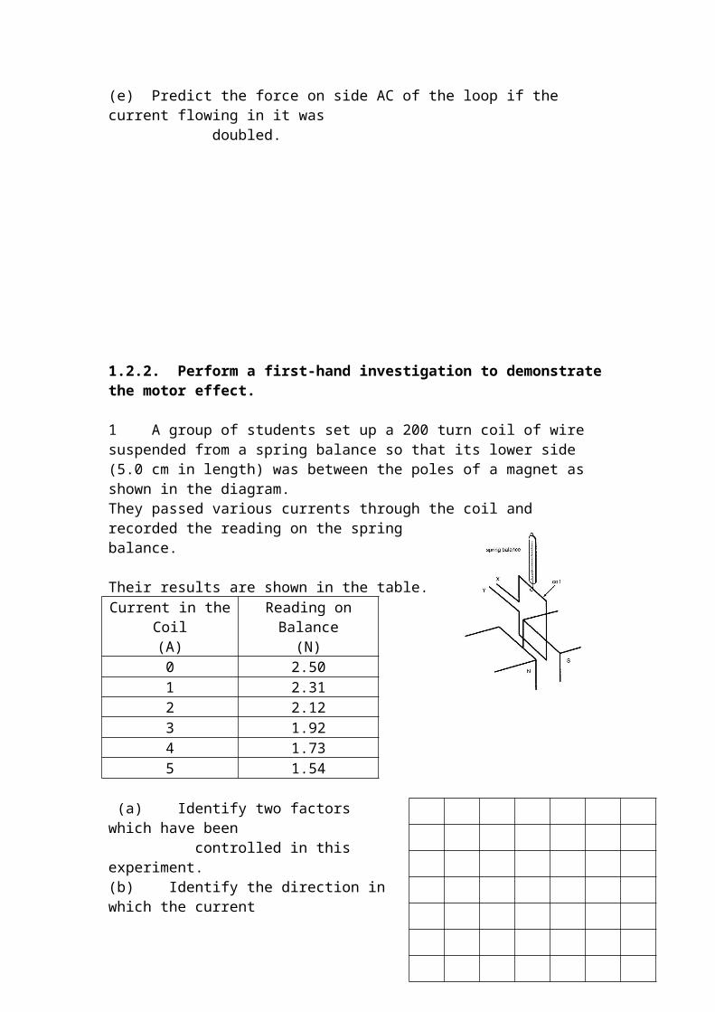
1 A group of students set up a 200 turn coil of wire suspended from a spring balance so that its lower side (5.0 cm in length) was between the poles of a magnet as shown in the diagram.They passed various currents through the coil and recorded the reading on the spring balance.
Their results are shown in the table.Current in the Coil
(A)Reading on Balance
(N)0 2.501 2.312 2.123 1.924 1.735 1.54
(a) Identify two factors which have been controlled in this experiment.(b) Identify the direction in which the current must flow through the coil in order to get the results shown (X to Y or Y to X).(c) Graph the results.
(d) Use the graph to determine the mass of the coil.(e) Use the graph to determine the strength of the magnetic field
(f) Use the graph to determine the reading on the spring balance if 11 A was flowing through the coil.(g) The students then repeated the experiment using a magnet twice as strong. On your graph, predict the line you would get if you graphed the new results. Label it 'X'.(h) They then repeated the experiment with the original magnet, but with a 100 turn coil. Draw another graph (on the same axes) to predict the results for this experiment. Label it 'Y'.(i) They then repeated the experiment with the original coil and magnet, but with three times the current flowing. Draw another graph (on the same axes) to predict the results for this experiment. Label it 'Z'.(j) The other dimension of the coil was 9.0 em. If this side was hung between the poles of the magnet how would the results have differed from those in the table? Justify your answer.

1.1.3 Define torque as the turning moment of a force using:
1 Define torque.2 Identify each of the symbols in the equation and the units used to measure them.
1.2.4 Solve problems and analyse information about simple motors using: 1.8.1 A 5.0 cm square coil with 150 turns of wire is in a magnetic field of intensity 0.25 T. The plane of the coil makes an angle of 30' with the magnetic field. The coil carries a current of 3.0 A.
(a) Calculate the magnitude of the force acting on each side of the coil.(b) Calculate the torque on the coil.(c) Predict the position of the coil relative to the magnetic field when the torque on it is maximum.(d) Predict the position of the coil relative to the magnetic field when the torque on it is minimum.
2 Using an appropriate diagram, describe how the torque on a current-carrying coil in a magnetic field changes as the coil rotates through 360'.
1.1.4 Identify that the motor effect is due to the force acting on a current-carrying conductor in a magnetic field.
1 Define the motor effect.
2 Explain how the direction of the force on a current-carrying conductor in a magnetic field is determined. Use a diagram.
3 Predict the direction of the force on the following current carrying conductors in magnetic fields
1.2.5 Describe the application of the motor effect in a galvanometer.
1 With the aid of a suitable diagram explain, referring to all the principles in physics involved how a galvanometer works.
2 Explain why the pointer of a moving coil galvanometer returns to the zero position when the current flowing through the circuit is turned off.
3 Explain why radial magnets are used in a moving coil galvanometer.
1.2.5 Describe the application of the motor effect in a loudspeaker.
1 With the aid of a diagram, explain, referring to the principles of physics involved, how a loudspeaker works.2 Explain how sounds with different pitches are produced by a loudspeaker.3 Explain what happens inside a loudspeaker when you 'turn up the volume'.
1.1.6 Describe the main features of a DC electric motor and the role of each feature.
1 Use the diagram below to answer this question.
(a) Which way will the coil shown in the diagram above rotate?(b) Explain two ways the efficiency of the motor above could be improved.(c) Complete the table:Part Name Function(s) of PartAB etc

1.1.7 Identify that the required magnetic field in DC motors can be produced by either current-carrying coils or permanent magnets.
1 Explain the advantage of using electromagnets in a motor compared to using conventional magnets.
2 Draw field lines to indicate the shape of the magnetic field around the coils.