mf9100 series pm
DESCRIPTION
klolTRANSCRIPT

Aug 22 2008
Portable Manual
MF9100 Series

ApplicationThis manual has been issued by Canon Inc. for qualified persons to learn technical theory, installation, maintenance, and repair
of products. This manual covers all localities where the products are sold. For this reason, there may be information in this
manual that does not apply to your locality.
CorrectionsThis manual may contain technical inaccuracies or typographical errors due to improvements or changes in products. When
changes occur in applicable products or in the contents of this manual, Canon will release technical information as the need
arises. In the event of major changes in the contents of this manual over a long or short period, Canon will issue a new edition
of this manual.
The following paragraph does not apply to any countries where such provisions are inconsistent with local law.
TrademarksThe product names and company names used in this manual are the registered trademarks of the individual companies.
CopyrightThis manual is copyrighted with all rights reserved. Under the copyright laws, this manual may not be copied, reproduced or
translated into another language, in whole or in part, without the written consent of Canon Inc.
COPYRIGHT © 2001 CANON INC.Printed in Japan
CautionUse of this manual should be strictly supervised to avoid disclosure of confidential information.
Introduction
Symbols UsedThis documentation uses the following symbols to indicate special information:
Symbol Description
Indicates an item of a non-specific nature, possibly classified as Note, Caution, or Warning.
Indicates an item requiring care to avoid electric shocks.
Indicates an item requiring care to avoid combustion (fire).
Indicates an item prohibiting disassembly to avoid electric shocks or problems.
Indicates an item requiring disconnection of the power plug from the electric outlet.
Indicates an item intended to provide notes assisting the understanding of the topic in question.
Indicates an item of reference assisting the understanding of the topic in question.
Provides a description of a service mode.
Provides a description of the nature of an error indication.
Memo
REF.

Introduction
The following rules apply throughout this Service Manual:1. Each chapter contains sections explaining the purpose of specific functions and the relationship between electrical and mechanical systems with refer-
ence to the timing of operation.In the diagrams, represents the path of mechanical drive; where a signal name accompanies the symbol , the arrow indicates thedirection of the electric signal.The expression "turn on the power" means flipping on the power switch, closing the front door, and closing the delivery unit door, which results insupplying the machine with power.
2. In the digital circuits, '1'is used to indicate that the voltage level of a given signal is "High", while '0' is used to indicate "Low".(The voltage value, how-ever, differs from circuit to circuit.) In addition, the asterisk (*) as in "DRMD*" indicates that the DRMD signal goes on when '0'.In practically all cases, the internal mechanisms of a microprocessor cannot be checked in the field. Therefore, the operations of the microprocessorsused in the machines are not discussed: they are explained in terms of from sensors to the input of the DC controller PCB and from the output of theDC controller PCB to the loads.
The descriptions in this Service Manual are subject to change without notice for product improvement or other purposes, and major changes will be com-municated in the form of Service Information bulletins.All service persons are expected to have a good understanding of the contents of this Service Manual and all relevant Service Information bulletins and beable to identify and isolate faults in the machine."

Contents
Contents
Chapter 1 Maintenance and Inspection
1.1 Periodically Replaced Parts ...............................................................................................................................11.1.1Periodically Replaced Parts .........................................................................................................................1
1.2 Durables and Consumables...............................................................................................................................11.2.1Expected Service Life of Consumable Parts .............................................................................................1
1.3 Scheduled Servicing Basic Procedure .............................................................................................................11.3.1Periodic Service .............................................................................................................................................1
Chapter 2 Standards and Adjustments
2.1 Scanning System .................................................................................................................................................32.1.1Procedure after Replacing the Copyboard Glass .....................................................................................3
2.2 Fixing System .......................................................................................................................................................32.2.1Checking the Nip Width (fixing pressure roller) ........................................................................................3
2.3 Electrical Components ........................................................................................................................................32.3.1Procedure after Replacing the DC controller PCB ...................................................................................32.3.2Procedure after Replacing the Main Controller PCB ...............................................................................32.3.3Actions to Take before All Clearing (Backing up the User Data) ...........................................................4
Chapter 3 Error Code
3.1 Error Code Details ...............................................................................................................................................53.1.1Error Code Details .........................................................................................................................................5
3.2 Jam Code............................................................................................................................................................113.2.1Jam Code (main body)................................................................................................................................113.2.2Jam Code (ADF) ..........................................................................................................................................11
3.3 Alarm Code .........................................................................................................................................................123.3.1Alarm Code (ADF) .......................................................................................................................................12
Chapter 4 User Mode Items
4.1 User Mode Items................................................................................................................................................134.1.1Overview .......................................................................................................................................................134.1.2Volume Settings ...........................................................................................................................................134.1.3Printer Settings.............................................................................................................................................144.1.4Timer Settings ..............................................................................................................................................164.1.5Report Settings ............................................................................................................................................17
Chapter 5 Service Mode
5.1 COPIER...............................................................................................................................................................195.1.1 DISPLAY.......................................................................................................................................................19
5.1.1.1 DISPLAY List ........................................................................................................................................19

Contents
5.1.2 I/O.................................................................................................................................................................. 195.1.2.1 R-CON .................................................................................................................................................. 19
5.1.3 ADJUST ....................................................................................................................................................... 195.1.3.1 ADJUST List......................................................................................................................................... 19
5.1.4 FUNCTION .................................................................................................................................................. 245.1.4.1 FUNCTION List ................................................................................................................................... 24
5.1.5 OPTION........................................................................................................................................................ 295.1.5.1 OPTION List......................................................................................................................................... 29
5.1.6 COUNTER ................................................................................................................................................... 385.1.6.1 COUNTER List .................................................................................................................................... 38
5.2 FEEDER ............................................................................................................................................................. 405.2.1 ADJUST ....................................................................................................................................................... 40
5.2.1.1 ADJUST List......................................................................................................................................... 405.2.2 FUNCTION .................................................................................................................................................. 40
5.2.2.1 FUNCTION List ................................................................................................................................... 405.3 FAX...................................................................................................................................................................... 40
5.3.1 SSSW ........................................................................................................................................................... 405.3.1.1 SSSW List ............................................................................................................................................ 40
5.3.2 MENU ........................................................................................................................................................... 425.3.2.1 MENU List ............................................................................................................................................ 42
5.3.3 NUM .............................................................................................................................................................. 425.3.3.1 NUM List ............................................................................................................................................... 42
5.3.4 NCU .............................................................................................................................................................. 425.3.4.1 NCU List ............................................................................................................................................... 42
5.4 TESTMODE ....................................................................................................................................................... 475.4.1 SYSTEM ...................................................................................................................................................... 47
5.4.1.1 SYSTEM List........................................................................................................................................ 475.4.2 SCAN ............................................................................................................................................................ 47
5.4.2.1 SCAN List ............................................................................................................................................. 475.4.3 PRINT ........................................................................................................................................................... 48
5.4.3.1 PRINT List ............................................................................................................................................ 485.4.4 FAX ............................................................................................................................................................... 49
5.4.4.1 FAX List ................................................................................................................................................ 495.4.5 PANEL .......................................................................................................................................................... 49
5.4.5.1 PANEL List ........................................................................................................................................... 49
Chapter 6 Outline of Components
6.1 Clutch/Solenoid ................................................................................................................................................. 516.1.1Solenoids ...................................................................................................................................................... 51
6.2 Sensor................................................................................................................................................................. 526.2.1Sensors......................................................................................................................................................... 52
6.3 Switch.................................................................................................................................................................. 546.3.1Switches, Speaker, and Thermistors ....................................................................................................... 54
6.4 PCBs ................................................................................................................................................................... 566.4.1PCBs ............................................................................................................................................................. 56
6.5 Location of Convectors .................................................................................................................................... 586.5.1Location of Connectors .............................................................................................................................. 58
Contents
Chapter 7 System Construction
7.1 Construction........................................................................................................................................................657.1.1Functional Configuration.............................................................................................................................657.1.2Connecting the Main PCBs ........................................................................................................................66
7.2 System Construction .........................................................................................................................................677.2.1System Configuration of Pickup/Delivery Options..................................................................................677.2.2System Configuration of Print/Send Options...........................................................................................68
7.3 Product Specifications ......................................................................................................................................687.3.1Main Body Specifications ...........................................................................................................................687.3.2Main Body Specifications ...........................................................................................................................707.3.3ADF Specifications ......................................................................................................................................717.3.4FAX Specifications ......................................................................................................................................73
7.4 Function List .......................................................................................................................................................747.4.1Print Speed ...................................................................................................................................................747.4.2Print Speed ...................................................................................................................................................757.4.3Paper Type ...................................................................................................................................................76
Chapter 8 Upgrading
8.1 Upgrading............................................................................................................................................................778.1.1Overview of Upgrade ..................................................................................................................................77


Chapter 1
1
Chapter 1 Maintenance and Inspection
1.1 Periodically Replaced Parts
1.1.1 Periodically Replaced Parts0019-4954
i-SENSYS MF9170 / i-SENSYS MF9130 / i-SENSYS MF8450
This machine does not have parts that require periodical replacement.
1.2 Durables and Consumables
1.2.1 Expected Service Life of Consumable Parts0019-4956
i-SENSYS MF9170 / i-SENSYS MF9130 / i-SENSYS MF8450
Some parts of the machine are likely to require replacement once or more because of wear or damage. Replace them when they are found to be faulty by referringto the following table:
F-1-1T-1-1
1.3 Scheduled Servicing Basic Procedure
1.3.1 Periodic Service0019-4955
i-SENSYS MF9170 / i-SENSYS MF9130 / i-SENSYS MF8450
This machine does not have parts that require periodic servicing.
No Parts name Parts No. Q'ty Estimated life[1] ADF separation roller FL2-6637 1 50,000 sheets[2] ADF separation pad FC7-6297 1 50,000 sheets[3] Duplex fan RK2-0954 1 25,000 hours[4] Main body fan RK2-0954 1 25,000 hours
*: The estimated life in the case of continuous power distribution at 24 hours/day for 25,000 hours is nearly equivalent to 3 years.(It is nearly equivalent to 5 years in the case of power distribution at 14 hours/day.)
[1]
[2]
[3]
[4]

Chapter 2
3
Chapter 2 Standards and Adjustments
2.1 Scanning System
2.1.1 Procedure after Replacing the Copyboard Glass0020-1580
i-SENSYS MF9170 / i-SENSYS MF9130 / i-SENSYS MF8450
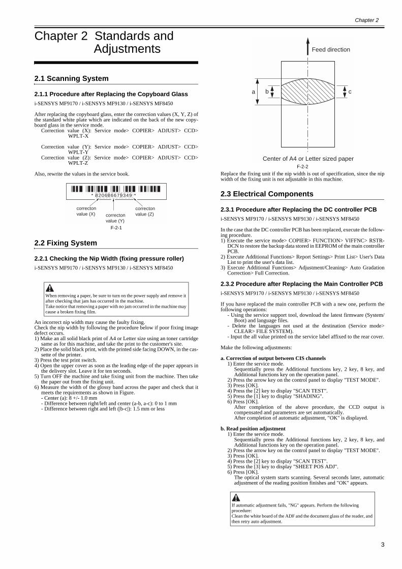
After replacing the copyboard glass, enter the correction values (X, Y, Z) ofthe standard white plate which are indicated on the back of the new copy-board glass in the service mode.
Correction value (X): Service mode> COPIER> ADJUST> CCD>WPLT-X
Correction value (Y): Service mode> COPIER> ADJUST> CCD>WPLT-Y
Correction value (Z): Service mode> COPIER> ADJUST> CCD>WPLT-Z
Also, rewrite the values in the service book.
F-2-1
2.2 Fixing System
2.2.1 Checking the Nip Width (fixing pressure roller)0019-5106
i-SENSYS MF9170 / i-SENSYS MF9130 / i-SENSYS MF8450
An incorrect nip width may cause the faulty fixing.Check the nip width by following the procedure below if poor fixing imagedefect occurs.1) Make an all solid black print of A4 or Letter size using an toner cartridge
same as for this machine, and take the print to the customer's site.2) Place the solid black print, with the printed side facing DOWN, in the cas-
sette of the printer.3) Press the test print switch.4) Open the upper cover as soon as the leading edge of the paper appears in
the delivery slot. Leave it for ten seconds.5) Turn OFF the machine and take fixing unit from the machine. Then take
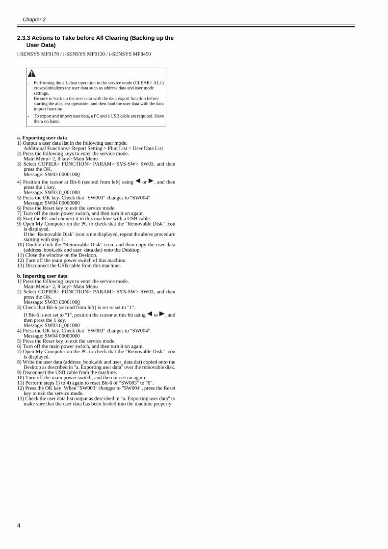
the paper out from the fixing unit.6) Measure the width of the glossy band across the paper and check that it
meets the requirements as shown in Figure.- Center (a): 8 +/- 1.0 mm- Difference between right/left and center (a-b, a-c): 0 to 1 mm- Difference between right and left (|b-c|): 1.5 mm or less
F-2-2Replace the fixing unit if the nip width is out of specification, since the nipwidth of the fixing unit is not adjustable in this machine.
2.3 Electrical Components
2.3.1 Procedure after Replacing the DC controller PCB0019-8983
i-SENSYS MF9170 / i-SENSYS MF9130 / i-SENSYS MF8450
In the case that the DC controller PCB has been replaced, execute the follow-ing procedure.1) Execute the service mode> COPIER> FUNCTION> VIFFNC> RSTR-
DCN to restore the backup data stored in EEPROM of the main controllerPCB.
2) Execute Additional Functions> Report Settings> Print List> User's DataList to print the user's data list.
3) Execute Additional Functions> Adjustment/Cleaning> Auto GradationCorrection> Full Correction.
2.3.2 Procedure after Replacing the Main Controller PCB0019-8984
i-SENSYS MF9170 / i-SENSYS MF9130 / i-SENSYS MF8450
If you have replaced the main controller PCB with a new one, perform thefollowing operations:
- Using the service support tool, download the latest firmware (System/Boot) and language files.
- Delete the languages not used at the destination (Service mode>CLEAR> FILE SYSTEM).
- Input the all value printed on the service label affixed to the rear cover.
Make the following adjustments:
a. Correction of output between CIS channels1) Enter the service mode.
Sequentially press the Additional functions key, 2 key, 8 key, andAdditional functions key on the operation panel.
2) Press the arrow key on the control panel to display "TEST MODE".3) Press [OK].4) Press the [2] key to display "SCAN TEST".5) Press the [1] key to display "SHADING".6) Press [OK].
After completion of the above procedure, the CCD output iscompensated and parameters are set automatically. After completion of automatic adjustment, "OK" is displayed.
b. Read position adjustment1) Enter the service mode.
Sequentially press the Additional functions key, 2 key, 8 key, andAdditional functions key on the operation panel.
2) Press the arrow key on the control panel to display "TEST MODE".3) Press [OK].4) Press the [2] key to display "SCAN TEST".5) Press the [3] key to display "SHEET POS ADJ".6) Press [OK].
The optical system starts scanning. Several seconds later, automaticadjustment of the reading position finishes and "OK" appears.
When removing a paper, be sure to turn on the power supply and remove it after checking that jam has occurred in the machine.Take notice that removing a paper with no jam occurred in the machine may cause a broken fixing film.
* 820686679349 *
correcton value (X) correcton
value (Y)
correctonvalue (Z)
If automatic adjustment fails, "NG" appears. Perform the following procedure:Clean the white board of the ADF and the document glass of the reader, and then retry auto adjustment.
Feed direction
ca b
Center of A4 or Letter sized paper
Chapter 2
4
2.3.3 Actions to Take before All Clearing (Backing up the User Data)
0020-1581
i-SENSYS MF9170 / i-SENSYS MF9130 / i-SENSYS MF8450
a. Exporting user data1) Output a user data list in the following user mode.
Additional Functions> Report Setting > Plint List > User Data List2) Press the following keys to enter the service mode.
Main Menu> 2, 8 key> Main Menu3) Select COPIER> FUNCTION> PARAM> SYS-SW> SW03, and then
press the OK.Message: SW03 00001000
4) Position the cursor at Bit-6 (second from left) using or , and thenpress the 1 key.Message: SW03 01001000
5) Press the OK key. Check that "SW003" changes to "SW004".Message: SW04 00000000
6) Press the Reset key to exit the service mode.7) Turn off the main power switch, and then turn it on again.8) Start the PC and connect it to this machine with a USB cable.9) Open My Computer on the PC to check that the "Removable Disk" icon
is displayed.If the "Removable Disk" icon is not displayed, repeat the above procedurestarting with step 1.
10) Double-click the "Removable Disk" icon, and then copy the user data(address_book.abk and user_data.dat) onto the Desktop.
11) Close the window on the Desktop.12) Turn off the main power switch of this machine.13) Disconnect the USB cable from this machine.
b. Importing user data1) Press the following keys to enter the service mode.
Main Menu> 2, 8 key> Main Menu2) Select COPIER> FUNCTION> PARAM> SYS-SW> SW03, and then
press the OK.Message: SW03 00001000
3) Check that Bit-6 (second from left) is set to set to "1".If Bit-6 is not set to "1", position the cursor at this bit using or , andthen press the 1 key.Message: SW03 01001000
4) Press the OK key. Check that "SW003" changes to "SW004".Message: SW04 00000000
5) Press the Reset key to exit the service mode.6) Turn off the main power switch, and then turn it on again.7) Open My Computer on the PC to check that the "Removable Disk" icon
is displayed.8) Write the user data (address_book.abk and user_data.dat) copied onto the
Desktop as described in "a. Exporting user data" over the removable disk.9) Disconnect the USB cable from the machine.10) Turn off the main power switch, and then turn it on again.11) Perform steps 1) to 4) again to reset Bit-6 of "SW003" to "0".12) Press the OK key. When "SW003" changes to "SW004", press the Reset
key to exit the service mode.13) Check the user data list output as described in "a. Exporting user data" to
make sure that the user data has been loaded into the machine properly.
- Performing the all-clear operation in the service mode (CLEAR> ALL) erases/initializes the user data such as address data and user mode settings.Be sure to back up the user data with the data export function before starting the all-clear operation, and then load the user data with tbe data import function.
- To export and import user data, a PC and a USB cable are required. Have them on hand.
Chapter 3
5
Chapter 3 Error Code
3.1 Error Code Details
3.1.1 Error Code Details0020-4452
i-SENSYS MF9170 / i-SENSYS MF9130 / i-SENSYS MF8450
T-3-1
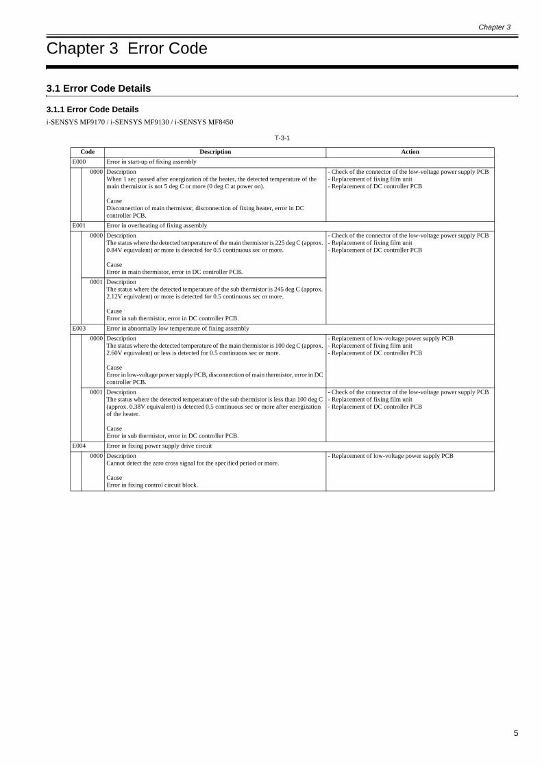
Code Description ActionE000 Error in start-up of fixing assembly
0000 DescriptionWhen 1 sec passed after energization of the heater, the detected temperature of the main thermistor is not 5 deg C or more (0 deg C at power on).
CauseDisconnection of main thermistor, disconnection of fixing heater, error in DC controller PCB.
- Check of the connector of the low-voltage power supply PCB- Replacement of fixing film unit- Replacement of DC controller PCB
E001 Error in overheating of fixing assembly0000 Description
The status where the detected temperature of the main thermistor is 225 deg C (approx. 0.84V equivalent) or more is detected for 0.5 continuous sec or more.
CauseError in main thermistor, error in DC controller PCB.
- Check of the connector of the low-voltage power supply PCB- Replacement of fixing film unit- Replacement of DC controller PCB
0001 DescriptionThe status where the detected temperature of the sub thermistor is 245 deg C (approx. 2.12V equivalent) or more is detected for 0.5 continuous sec or more.
CauseError in sub thermistor, error in DC controller PCB.
E003 Error in abnormally low temperature of fixing assembly0000 Description
The status where the detected temperature of the main thermistor is 100 deg C (approx. 2.60V equivalent) or less is detected for 0.5 continuous sec or more.
CauseError in low-voltage power supply PCB, disconnection of main thermistor, error in DC controller PCB.
- Replacement of low-voltage power supply PCB- Replacement of fixing film unit- Replacement of DC controller PCB
0001 DescriptionThe status where the detected temperature of the sub thermistor is less than 100 deg C (approx. 0.38V equivalent) is detected 0.5 continuous sec or more after energization of the heater.
CauseError in sub thermistor, error in DC controller PCB.
- Check of the connector of the low-voltage power supply PCB- Replacement of fixing film unit- Replacement of DC controller PCB
E004 Error in fixing power supply drive circuit0000 Description
Cannot detect the zero cross signal for the specified period or more.
CauseError in fixing control circuit block.
- Replacement of low-voltage power supply PCB
Chapter 3
6
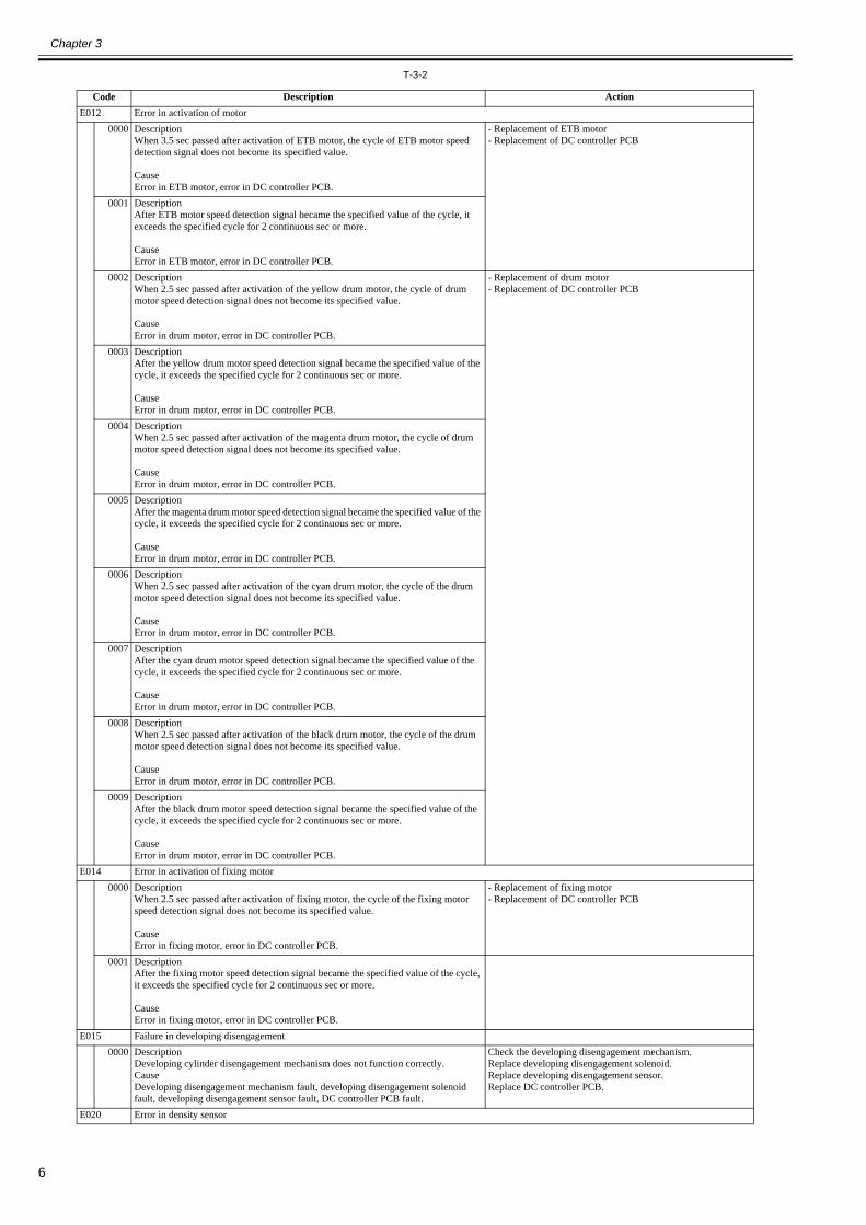
T-3-2
Code Description ActionE012 Error in activation of motor
0000 DescriptionWhen 3.5 sec passed after activation of ETB motor, the cycle of ETB motor speed detection signal does not become its specified value.
CauseError in ETB motor, error in DC controller PCB.
- Replacement of ETB motor- Replacement of DC controller PCB
0001 DescriptionAfter ETB motor speed detection signal became the specified value of the cycle, it exceeds the specified cycle for 2 continuous sec or more.
CauseError in ETB motor, error in DC controller PCB.
0002 DescriptionWhen 2.5 sec passed after activation of the yellow drum motor, the cycle of drum motor speed detection signal does not become its specified value.
CauseError in drum motor, error in DC controller PCB.
- Replacement of drum motor- Replacement of DC controller PCB
0003 DescriptionAfter the yellow drum motor speed detection signal became the specified value of the cycle, it exceeds the specified cycle for 2 continuous sec or more.
CauseError in drum motor, error in DC controller PCB.
0004 DescriptionWhen 2.5 sec passed after activation of the magenta drum motor, the cycle of drum motor speed detection signal does not become its specified value.
CauseError in drum motor, error in DC controller PCB.
0005 DescriptionAfter the magenta drum motor speed detection signal became the specified value of the cycle, it exceeds the specified cycle for 2 continuous sec or more.
CauseError in drum motor, error in DC controller PCB.
0006 DescriptionWhen 2.5 sec passed after activation of the cyan drum motor, the cycle of the drum motor speed detection signal does not become its specified value.
CauseError in drum motor, error in DC controller PCB.
0007 DescriptionAfter the cyan drum motor speed detection signal became the specified value of the cycle, it exceeds the specified cycle for 2 continuous sec or more.
CauseError in drum motor, error in DC controller PCB.
0008 DescriptionWhen 2.5 sec passed after activation of the black drum motor, the cycle of the drum motor speed detection signal does not become its specified value.
CauseError in drum motor, error in DC controller PCB.
0009 DescriptionAfter the black drum motor speed detection signal became the specified value of the cycle, it exceeds the specified cycle for 2 continuous sec or more.
CauseError in drum motor, error in DC controller PCB.
E014 Error in activation of fixing motor0000 Description
When 2.5 sec passed after activation of fixing motor, the cycle of the fixing motor speed detection signal does not become its specified value.
CauseError in fixing motor, error in DC controller PCB.
- Replacement of fixing motor- Replacement of DC controller PCB
0001 DescriptionAfter the fixing motor speed detection signal became the specified value of the cycle, it exceeds the specified cycle for 2 continuous sec or more.
CauseError in fixing motor, error in DC controller PCB.
E015 Failure in developing disengagement0000 Description
Developing cylinder disengagement mechanism does not function correctly.CauseDeveloping disengagement mechanism fault, developing disengagement solenoid fault, developing disengagement sensor fault, DC controller PCB fault.
Check the developing disengagement mechanism.Replace developing disengagement solenoid.Replace developing disengagement sensor.Replace DC controller PCB.
E020 Error in density sensor

Chapter 3
7
0000 DescriptionCannot receive enough light when detecting image density.
CauseDirt on density sensor, error in density sensor, error in DC controller PCB, error in toner cartridge.
- Replacement of ETB unit- Error in high-voltage joint (Check high-voltage joint for each color, and each joint to high-voltage PCB)- Replacement of DC controller- Replacement of toner cartridge
Code Description Action
Chapter 3
8
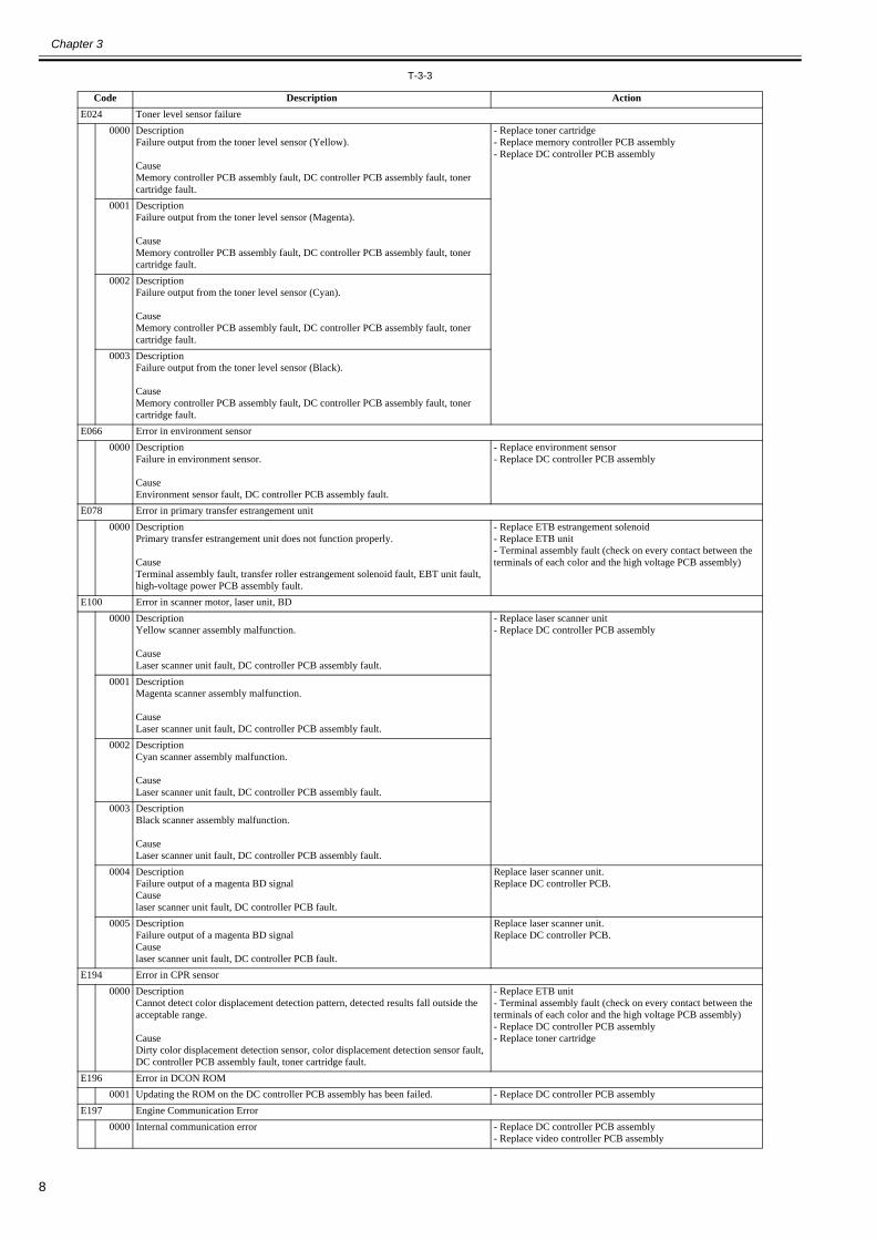
T-3-3
Code Description ActionE024 Toner level sensor failure
0000 DescriptionFailure output from the toner level sensor (Yellow).
CauseMemory controller PCB assembly fault, DC controller PCB assembly fault, toner cartridge fault.
- Replace toner cartridge- Replace memory controller PCB assembly- Replace DC controller PCB assembly
0001 DescriptionFailure output from the toner level sensor (Magenta).
CauseMemory controller PCB assembly fault, DC controller PCB assembly fault, toner cartridge fault.
0002 DescriptionFailure output from the toner level sensor (Cyan).
CauseMemory controller PCB assembly fault, DC controller PCB assembly fault, toner cartridge fault.
0003 DescriptionFailure output from the toner level sensor (Black).
CauseMemory controller PCB assembly fault, DC controller PCB assembly fault, toner cartridge fault.
E066 Error in environment sensor0000 Description
Failure in environment sensor.
CauseEnvironment sensor fault, DC controller PCB assembly fault.
- Replace environment sensor- Replace DC controller PCB assembly
E078 Error in primary transfer estrangement unit0000 Description
Primary transfer estrangement unit does not function properly.
CauseTerminal assembly fault, transfer roller estrangement solenoid fault, EBT unit fault, high-voltage power PCB assembly fault.
- Replace ETB estrangement solenoid- Replace ETB unit- Terminal assembly fault (check on every contact between the terminals of each color and the high voltage PCB assembly)
E100 Error in scanner motor, laser unit, BD0000 Description
Yellow scanner assembly malfunction.
CauseLaser scanner unit fault, DC controller PCB assembly fault.
- Replace laser scanner unit- Replace DC controller PCB assembly
0001 DescriptionMagenta scanner assembly malfunction.
CauseLaser scanner unit fault, DC controller PCB assembly fault.
0002 DescriptionCyan scanner assembly malfunction.
CauseLaser scanner unit fault, DC controller PCB assembly fault.
0003 DescriptionBlack scanner assembly malfunction.
CauseLaser scanner unit fault, DC controller PCB assembly fault.
0004 DescriptionFailure output of a magenta BD signalCauselaser scanner unit fault, DC controller PCB fault.
Replace laser scanner unit.Replace DC controller PCB.
0005 DescriptionFailure output of a magenta BD signalCauselaser scanner unit fault, DC controller PCB fault.
Replace laser scanner unit.Replace DC controller PCB.
E194 Error in CPR sensor0000 Description
Cannot detect color displacement detection pattern, detected results fall outside the acceptable range.
CauseDirty color displacement detection sensor, color displacement detection sensor fault, DC controller PCB assembly fault, toner cartridge fault.
- Replace ETB unit- Terminal assembly fault (check on every contact between the terminals of each color and the high voltage PCB assembly)- Replace DC controller PCB assembly- Replace toner cartridge
E196 Error in DCON ROM0001 Updating the ROM on the DC controller PCB assembly has been failed. - Replace DC controller PCB assembly
E197 Engine Communication Error0000 Internal communication error - Replace DC controller PCB assembly
- Replace video controller PCB assembly

Chapter 3
9
E198 DC controller memory malfunction0000 Description
DC controller memory malfunction.
CauseDC controller PCB assembly fault.
- Replace DC controller PCB assembly
Code Description Action
Chapter 3
10
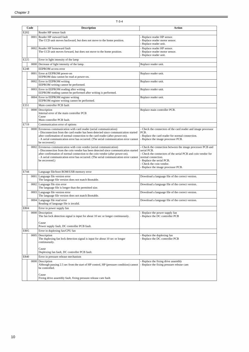
T-3-4
Code Description ActionE202 Reader HP sensor fault
0001 Reader HP outward faultThe CCD unit moves backward, but does not move to the home position.
- Replace reader HP sensor.- Replace reader motor sensor.- Replace reader unit.
0002 Reader HP homeward faultThe CCD unit moves forward, but does not move to the home position.
- Replace reader HP sensor.- Replace reader motor sensor.- Replace reader unit.
E225 Error in light intensity of the lamp0000 Decrease of light intensity of the lamp. Replace reader unit.
E248 EEPROM access error0001 Error at EEPROM power-on
EEPROM data cannot be read at power-on.Replace reader unit.
0002 Error in EEPROM writingEEPROM writing cannot be performed.
Replace reader unit.
0003 Error in EEPROM reading after writingEEPROM reading cannot be performed after writing is performed.
Replace reader unit.
0004 Error in EEPROM register writingEEPROM register writing cannot be performed.
Replace reader unit.
E351 Main controller PCB fault0000 Description
Internal error of the main controller PCBCauseMain controller PCB fault.
Replace main controller PCB.
E719 Communication error of options0000 Erroneous communication with card reader (serial communication)
- Disconnection from the card reader has been detected since communication started after confirmation of normal connection to the card reader (after power-on).- A serial communication error has occurred. (The serial communication error cannot be recovered.)
- Check the connectors of the card reader and image processor PCB.- Replace the card reader for normal connection.- Replace the image processor PCB.
0002 Erroneous communication with coin vendor (serial communication)- Disconnection from the coin vendor has been detected since communication started after confirmation of normal connection to the coin vendor (after power-on).- A serial communication error has occurred. (The serial communication error cannot be recovered.)
- Check the connection between the image processor PCB and serial PCB.- Check the connectors of the serial PCB and coin vendor for normal connection.- Replace the serial PCB.- Check the coin vendor.- Replace the image processor PCB.
E744 Language file/boot ROM/USB memory error0001 Language file version error
The language file version does not match Bootable.Download a language file of the correct version.
0002 Language file size errorThe language file is longer than the permitted size.
Download a language file of the correct version.
0003 Language file version errorThe language file version does not match Bootable.
Download a language file of the correct version.
0004 Language file read errorReading of language file is invalid.
Download a language file of the correct version.
E804 Error in power supply fan0000 Description
The fan lock detection signal is input for about 10 sec or longer continuously.
CausePower supply fault, DC controller PCB fault.
- Replace the power supply fan- Replace the DC controller PCB
E805 Error in duplexing fan/CPU fan0005 Description
The duplexing fan lock detection signal is input for about 10 sec or longer continuously.
CauseDuplexing fan fault, DC controller PCB fault.
- Replace the duplexing fan- Replace the DC controller PCB
E840 Error in pressure release mechanism0000 Description
Although passing 2.5 sec from the start of HP control, HP (pressure condition) cannot be controlled.
CauseFixing drive assembly fault, fixing pressure release cam fault.
- Replace the fixing drive assembly- Replace the fixing pressure release cam

Chapter 3
11
3.2 Jam Code
3.2.1 Jam Code (main body)0020-4442
i-SENSYS MF9170 / i-SENSYS MF9130 / i-SENSYS MF8450
T-3-5
3.2.2 Jam Code (ADF)0020-4444
i-SENSYS MF9170 / i-SENSYS MF9130 / i-SENSYS MF8450
T-3-6
Code Name Sensor No. Description 0104 Delay jam in paper pickup section SR710 The registration sensor cannot detect the leading edge of paper from the moment paper
pickup starts to the moment the jam detection time is reached. 0208 Stationary jam in paper pickup section SR710 The registration sensor cannot detect the no paper status specified time before the leading
edge of the picked up paper reaches this sensor.010c Delay jam in deliver section SR710, SR6005 - The fixing delivery sensor cannot detect presence of paper within the specified time after
turning on of the registration clutch.- The fixing delivery sensor detected absence of paper within the specified time after the sensor had detected presence of paper within the specified time after turning on of the registration clutch.- The No.1 delivery sensor cannot detect presence of paper within the specified time after turning on of the fixing delivery sensor.
0210 Stationary jam in delivery section SR710, SR6005 - The fixing delivery sensor cannot detect absence of paper within the specified time after turning off of the registration clutch.- The fixing delivery sensor cannot detect absence of paper within the specified time after the sensor detected the leading edge of paper.- The No.1 delivery sensor cannot detect absence of paper within the specified time after the sensor detected the leading edge of paper.
0214 Stationary jam in machine SR706, SR710, SR6001, SR6005
Paper was detected in the paper transport path during initial rotation, during automatic delivery, at the end of cleaning, or at reception of an emergency stop command.
1118 Door open jam SR720 The door was opened when there was printing paper in the transport path.
0221 Reverse section JAM SR706, SR715 This jam is applied when the double-fed paper drops on the back of the host machine.The machine determines the reverse section jam if the paper length that is detected by the reverse sensor (SR706) is 50mm or more longer than the paper length that is detected by the delivery sensor (SR715).
0228 Reverse re-pickup section jam SR710 The machine determines the reverse re-pickup jam if the registration sensor (SR710) cannot detect the presence of paper within the specified time (t) after the duplexing pickup starts.Specified time (t) differs depending on the feeding speed.1/1 speed: approx. 2.0 sec4/5 speed: approx. 2.5 sec1/2 speed: approx 4.0 sec
Code Name Sensor No. Description 0001 ADF paper trailing edge sensor (SR719)
not reaching (delay jam)SR719 The leading edge of paper does not reach the ADF paper trailing edge sensor (SR719) within
1.8 sec after the trailing edge of precedent page passes through the ADF paper trailing edge sensor (SR719) in 1-sided multiple jobs.The leading edge of paper does not reach the ADF paper trailing edge sensor (SR719) within 1.2 sec after reverse operation starts in 2-sided job.
0002 ADF paper trailing edge sensor (SR719) stray (stray jam)
SR719 The trailing edge of paper does not passes through the ADF paper trailing edge sensor (SR719) within 3.4 sec after the leading edge of paper reaches the ADF paper trailing edge sensor (SR719) in 1-sided job.The trailing edge of paper does not passes through the ADF paper trailing edge sensor (SR719) within 3.5 sec after the leading edge of paper reaches the ADF paper trailing edge sensor (SR719) in 2-sided job.
0094 Initial stationary (in-body residual jam) SR719 The ADF paper trailing edge sensor (SR719) detects paper at power-ON.
0095 Pickup NG SR718 The paper is removed from the ADF original tray within 0.1 sec after the start key is pressed.

Chapter 3
12
3.3 Alarm Code
3.3.1 Alarm Code (ADF)0020-9550
i-SENSYS MF9170 / i-SENSYS MF9130 / i-SENSYS MF8450
T-3-7
Code Name Sensor No. Description 0003H Separation NG alarm SR719 The leading edge of paper does not reach the ADF paper trailing edge sensor (SR719) within
3.2 sec after the ADF pickup motor starts positive rotation.

Chapter 4
13
Chapter 4 User Mode Items
4.1 User Mode Items
4.1.1 Overview0020-0865
i-SENSYS MF9170 / i-SENSYS MF9130 / i-SENSYS MF8450
The following are the user mode setting items.
4.1.2 Volume Settings0019-4897
i-SENSYS MF9170 / i-SENSYS MF9130 / i-SENSYS MF8450
*: default settings*3: Only when the Super G3 FAX Board is attached.
T-4-1
MEMO:- Drawer 2 is an option cassette.- Some setting items are displayed by pressing the left/right Any key. Perform operations by referring to the functions of the left/right Any key displayed at the bottom of the screen.
- Depending on the country of purchase, some settings may not be available.- The menus described in this section are based on the model Color imageRUNNER C1022i.- Depending on the model of your machine, some settings may not be available.
Volume SettingsItem Settings
Monitor Volume Settings *3 Volume Key Setting Priority *, Screen Settings PrioritySend Tone ON*/OFF
Volume 1*-3Audible Tones
Incoming Ring *3 ON*/OFFVolume 1*-3
Entry Tone ON*/OFFVolume 1*-3
Warning Tone ON*/OFFVolume 1*-3
TX Done Tone ON*/OFFVolume 1*-3
Receive Tone *3 ON*/OFFVolume 1*-3
Print Done Tone ON*/OFFVolume 1*-3
Scan Done Tone ON*/OFFVolume 1*-3
Chapter 4
14
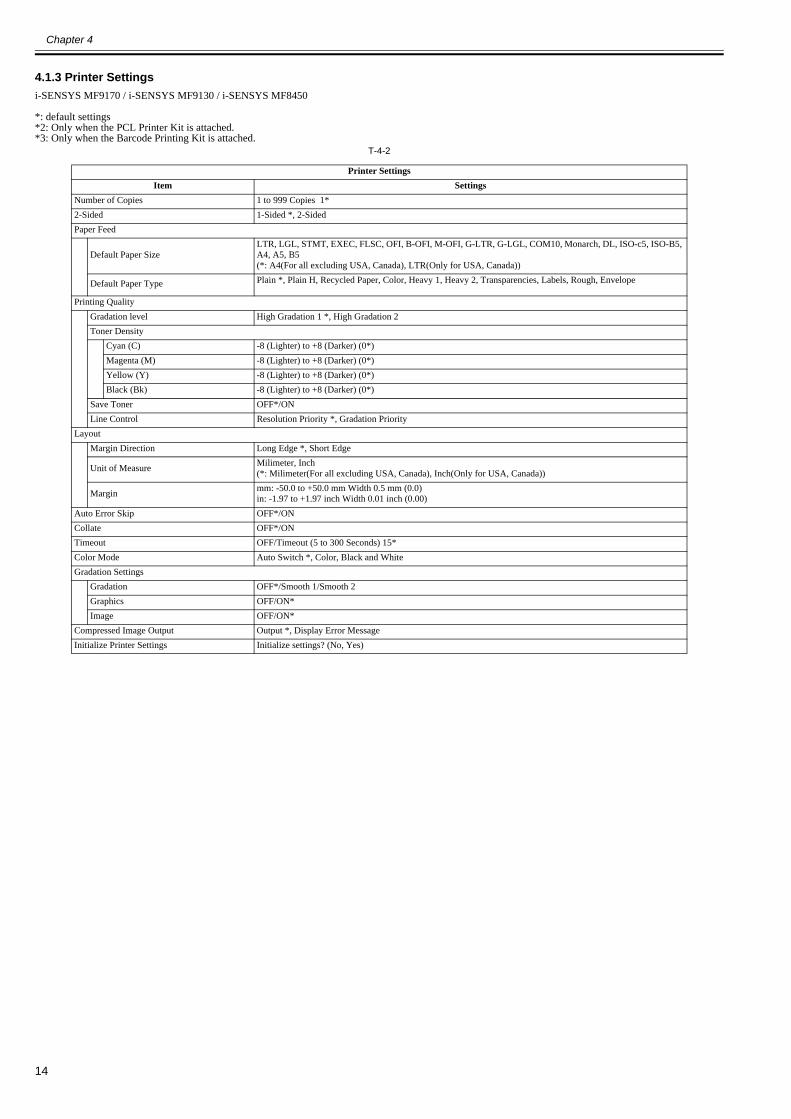
4.1.3 Printer Settings0020-9811
i-SENSYS MF9170 / i-SENSYS MF9130 / i-SENSYS MF8450
*: default settings*2: Only when the PCL Printer Kit is attached.*3: Only when the Barcode Printing Kit is attached.
T-4-2
Printer SettingsItem Settings
Number of Copies 1 to 999 Copies 1*2-Sided 1-Sided *, 2-SidedPaper Feed
Default Paper SizeLTR, LGL, STMT, EXEC, FLSC, OFI, B-OFI, M-OFI, G-LTR, G-LGL, COM10, Monarch, DL, ISO-c5, ISO-B5, A4, A5, B5(*: A4(For all excluding USA, Canada), LTR(Only for USA, Canada))
Default Paper Type Plain *, Plain H, Recycled Paper, Color, Heavy 1, Heavy 2, Transparencies, Labels, Rough, Envelope
Printing QualityGradation level High Gradation 1 *, High Gradation 2Toner Density
Cyan (C) -8 (Lighter) to +8 (Darker) (0*)Magenta (M) -8 (Lighter) to +8 (Darker) (0*)Yellow (Y) -8 (Lighter) to +8 (Darker) (0*)Black (Bk) -8 (Lighter) to +8 (Darker) (0*)
Save Toner OFF*/ONLine Control Resolution Priority *, Gradation Priority
LayoutMargin Direction Long Edge *, Short Edge
Unit of Measure Milimeter, Inch(*: Milimeter(For all excluding USA, Canada), Inch(Only for USA, Canada))
Margin mm: -50.0 to +50.0 mm Width 0.5 mm (0.0)in: -1.97 to +1.97 inch Width 0.01 inch (0.00)
Auto Error Skip OFF*/ONCollate OFF*/ONTimeout OFF/Timeout (5 to 300 Seconds) 15*Color Mode Auto Switch *, Color, Black and WhiteGradation Settings
Gradation OFF*/Smooth 1/Smooth 2Graphics OFF/ON*Image OFF/ON*
Compressed Image Output Output *, Display Error MessageInitialize Printer Settings Initialize settings? (No, Yes)
Chapter 4
15
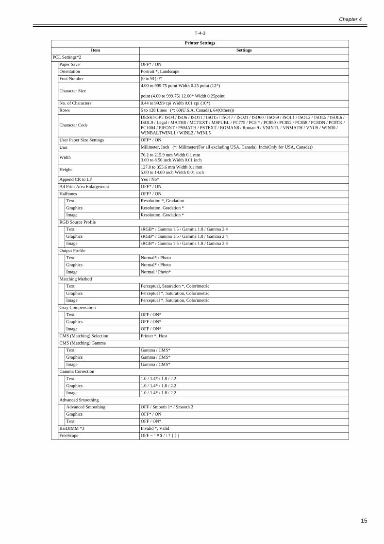
T-4-3
Printer SettingsItem Settings
PCL Settings*2Paper Save OFF* / ONOrientation Portrait *, LandscapeFont Number (0 to 91) 0*
Character Size4.00 to 999.75 point Width 0.25 point (12*)
point (4.00 to 999.75) 12.00* Width 0.25pointNo. of Characters 0.44 to 99.99 cpi Width 0.01 cpi (10*)Rows 5 to 128 Lines (*: 60(U.S.A, Canada), 64(Others))
Character Code
DESKTOP / ISO4 / ISO6 / ISO11 / ISO15 / ISO17 / ISO21 / ISO60 / ISO69 / ISOL1 / ISOL2 / ISOL5 / ISOL6 / ISOL9 / Legal / MATH8 / MCTEXT / MSPUBL / PC775 / PC8 * / PC850 / PC852 / PC858 / PC8DN / PC8TK / PC1004 / PIFONT / PSMATH / PSTEXT / ROMAN8 / Roman 9 / VNINTL / VNMATH / VNUS / WIN30 / WINBALTWINL1 / WINL2 / WINL5
User Paper Size Settings OFF* / ON
Unit Milimeter, Inch (*: Milimeter(For all excluding USA, Canada), Inch(Only for USA, Canada))
Width 76.2 to 215.9 mm Width 0.1 mm3.00 to 8.50 inch Width 0.01 inch
Height 127.0 to 355.6 mm Width 0.1 mm5.00 to 14.00 inch Width 0.01 inch
Append CR to LF Yes / No*A4 Print Area Enlargement OFF* / ONHalftones OFF* / ON
Text Resolution *, GradationGraphics Resolution, Gradation *Image Resolution, Gradation *
RGB Source ProfileText sRGB* / Gamma 1.5 / Gamma 1.8 / Gamma 2.4Graphics sRGB* / Gamma 1.5 / Gamma 1.8 / Gamma 2.4Image sRGB* / Gamma 1.5 / Gamma 1.8 / Gamma 2.4
Output ProfileText Normal* / PhotoGraphics Normal* / PhotoImage Normal / Photo*
Matching MethodText Perceptual, Saturation *, ColorimetricGraphics Perceptual *, Saturation, ColorimetricImage Perceptual *, Saturation, Colorimetric
Gray CompensationText OFF / ON*Graphics OFF / ON*Image OFF / ON*
CMS (Matching) Selection Printer *, HostCMS (Matching) Gamma
Text Gamma / CMS*Graphics Gamma / CMS*Image Gamma / CMS*
Gamma CorrectionText 1.0 / 1.4* / 1.8 / 2.2Graphics 1.0 / 1.4* / 1.8 / 2.2Image 1.0 / 1.4* / 1.8 / 2.2
Advanced SmoothingAdvanced Smoothing OFF / Smooth 1* / Smooth 2Graphics OFF* / ONText OFF / ON*
BarDIMM *3 Invalid *, ValidFreeScape OFF ~ " # $ / \ ? { } |

Chapter 4
16
4.1.4 Timer Settings0019-4902
i-SENSYS MF9170 / i-SENSYS MF9130 / i-SENSYS MF8450
***: For all excluding Japan, AsiaThe following are the items for timer settings.1. Month 2. Week (1st/2nd/3rd/4th/End) 3. Day of week 4. Time(00 - 23): No setting by minutes
Default: No settingT-4-4
Timer SettingsItem Settings
Date/Time SettingsCurrent Time Settings YYYY MM / DD --:--
Time Zone Settings
1. GMT-12:002. GMT-11:003. GMT-10:004. GMT-9:005. GMT-8:006. GMT-7:007. GMT-6:008. GMT-5:00: Default for North America (EST)9. GMT-4:0010. GMT-3:3011. GMT-3:0012. GMT-2:0013. GMT-1:0014. GMT: Default for Europe/general15. GMT+1:0016. GMT+2:0017. GMT+3:0018. GMT+3:3019. GMT+4:0020. GMT+4:3021. GMT+5:0022. GMT+5:3023. GMT+6:0024. GMT+7:0025. GMT+8:0026. GMT+9:00: Default for Japan27. GMT+9:3028. GMT+10:0029. GMT+11:0030. GMT+12:00
Daylight Saving Time Set. *** OFF*/ONStart date
MonthWeekDay of weekTime
End dateMonthWeekDay of weekTime
Auto Sleep Time ON/OFFShift time 3 to 240 Minutes 15*
Auto Clear Time 0 = Off, 1 to 9 Minutes (by minutes) 2*

Chapter 4
17
4.1.5 Report Settings0019-4904
i-SENSYS MF9170 / i-SENSYS MF9130 / i-SENSYS MF8450
*: default settings*4: Only when the appropriate optional equipment is attached.
SettingsT-4-5
Print ListT-4-6
Report Settings > SettingsItem Settings
TX Report OFF/ON/Only When Error Occurs *Display Send Original OFF/ON*
Color Send Original Display *4 OFF/ON*Activity Report
Auto Print OFF/ON*Send/ Receive Separate *4 OFF*/ON
RX Report *4 OFF*/ON/Only When Error Occurs
Report Settings > Print ListItem Settings
Address Book List *4Address Book Do you want to print the address book list? No/YesOne-touch Do you want to print the address book list? No/Yes
User’s Data List Is it OK to print the user's data list? No/Yes

Chapter 4
18

Chapter 5
19
Chapter 5 Service Mode
5.1 COPIER
5.1.1 DISPLAY
5.1.1.1 DISPLAY List0020-2011
i-SENSYS MF9170 / i-SENSYS MF9130 / i-SENSYS MF8450
<VERSION>T-5-1
<ERR>Error code display screenDisplay error codes and detailed codes for system errors.128 errors maximum
F-5-1<CCD>
T-5-2
5.1.2 I/O
5.1.2.1 R-CON0020-2013
i-SENSYS MF9170 / i-SENSYS MF9130 / i-SENSYS MF8450
T-5-3
5.1.3 ADJUST
5.1.3.1 ADJUST List0020-2014
i-SENSYS MF9170 / i-SENSYS MF9130 / i-SENSYS MF8450
COPIER > DISPLAY > VERSIONSub item Description
MAIN Display of the version/checksum/date of Bootable (product program area)BOOT Display of the version/checksum/date of BootROM (boot program area)OPROM Not usedECONT Display of the ROM version of the recording engine
COPIER > DISPLAY > CCDSub item Description
TARGET-B BLUE color shading target valueTARGET-G GREEN color shading target valueTARGET-R RED color shading target valueGAIN-OB CCD odd-bit BLUE color gain level adjustment valueGAIN-OG CCD odd-bit GREEN color gain level adjustment valueGAIN-OR CCD odd-bit RED color gain level adjustment valueGAIN-EB CCD odd-bit BLUE color offset level adjustment valueGAIN-EG CCD odd-bit GREEN color offset level adjustment valueGAIN-ER CCD odd-bit RED color offset level adjustment value
Address BIT DescriptionP001 - Not usedP002 0 Display of the sensor status (DES)
1 Display of the sensor status (DS)2 Display of the sensor status (HPS)
Chapter 5
20
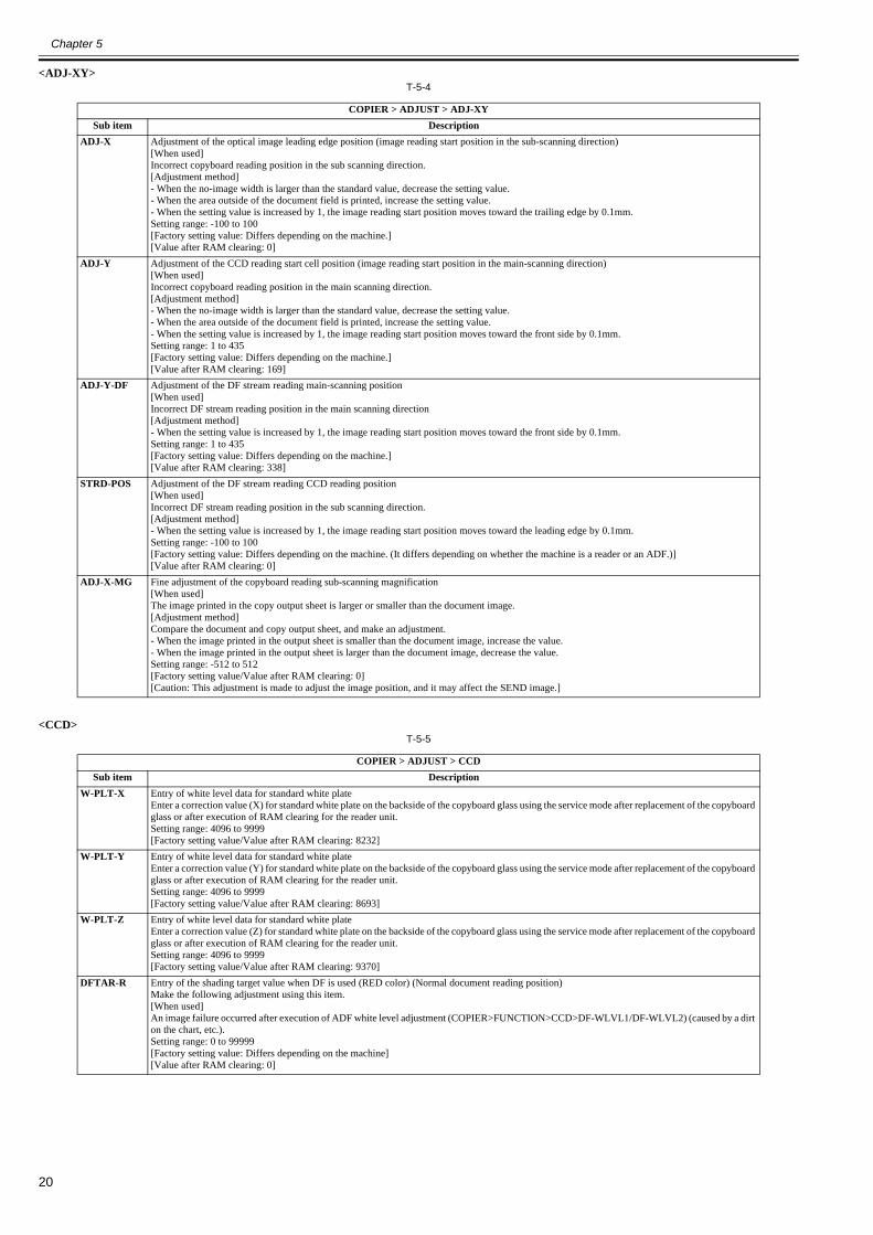
<ADJ-XY>T-5-4
<CCD>T-5-5
COPIER > ADJUST > ADJ-XYSub item Description
ADJ-X Adjustment of the optical image leading edge position (image reading start position in the sub-scanning direction)[When used]Incorrect copyboard reading position in the sub scanning direction.[Adjustment method]- When the no-image width is larger than the standard value, decrease the setting value.- When the area outside of the document field is printed, increase the setting value.- When the setting value is increased by 1, the image reading start position moves toward the trailing edge by 0.1mm.Setting range: -100 to 100[Factory setting value: Differs depending on the machine.][Value after RAM clearing: 0]
ADJ-Y Adjustment of the CCD reading start cell position (image reading start position in the main-scanning direction)[When used]Incorrect copyboard reading position in the main scanning direction.[Adjustment method]- When the no-image width is larger than the standard value, decrease the setting value.- When the area outside of the document field is printed, increase the setting value.- When the setting value is increased by 1, the image reading start position moves toward the front side by 0.1mm.Setting range: 1 to 435[Factory setting value: Differs depending on the machine.][Value after RAM clearing: 169]
ADJ-Y-DF Adjustment of the DF stream reading main-scanning position[When used]Incorrect DF stream reading position in the main scanning direction[Adjustment method]- When the setting value is increased by 1, the image reading start position moves toward the front side by 0.1mm.Setting range: 1 to 435[Factory setting value: Differs depending on the machine.][Value after RAM clearing: 338]
STRD-POS Adjustment of the DF stream reading CCD reading position[When used]Incorrect DF stream reading position in the sub scanning direction.[Adjustment method]- When the setting value is increased by 1, the image reading start position moves toward the leading edge by 0.1mm.Setting range: -100 to 100[Factory setting value: Differs depending on the machine. (It differs depending on whether the machine is a reader or an ADF.)][Value after RAM clearing: 0]
ADJ-X-MG Fine adjustment of the copyboard reading sub-scanning magnification[When used]The image printed in the copy output sheet is larger or smaller than the document image.[Adjustment method]Compare the document and copy output sheet, and make an adjustment.- When the image printed in the output sheet is smaller than the document image, increase the value.- When the image printed in the output sheet is larger than the document image, decrease the value.Setting range: -512 to 512[Factory setting value/Value after RAM clearing: 0][Caution: This adjustment is made to adjust the image position, and it may affect the SEND image.]
COPIER > ADJUST > CCDSub item Description
W-PLT-X Entry of white level data for standard white plateEnter a correction value (X) for standard white plate on the backside of the copyboard glass using the service mode after replacement of the copyboard glass or after execution of RAM clearing for the reader unit.Setting range: 4096 to 9999[Factory setting value/Value after RAM clearing: 8232]
W-PLT-Y Entry of white level data for standard white plateEnter a correction value (Y) for standard white plate on the backside of the copyboard glass using the service mode after replacement of the copyboard glass or after execution of RAM clearing for the reader unit.Setting range: 4096 to 9999[Factory setting value/Value after RAM clearing: 8693]
W-PLT-Z Entry of white level data for standard white plateEnter a correction value (Z) for standard white plate on the backside of the copyboard glass using the service mode after replacement of the copyboard glass or after execution of RAM clearing for the reader unit.Setting range: 4096 to 9999[Factory setting value/Value after RAM clearing: 9370]
DFTAR-R Entry of the shading target value when DF is used (RED color) (Normal document reading position)Make the following adjustment using this item.[When used]An image failure occurred after execution of ADF white level adjustment (COPIER>FUNCTION>CCD>DF-WLVL1/DF-WLVL2) (caused by a dirt on the chart, etc.).Setting range: 0 to 99999[Factory setting value: Differs depending on the machine][Value after RAM clearing: 0]

Chapter 5
21
<PASCAL>T-5-6
<MISC>T-5-7
<VIFADJ>T-5-8
DFTAR-G Entry of the shading target value when DF is used (GREEN color) (Normal document reading position)Make the following adjustment using this item.[When used]An image failure occurred after execution of ADF white level adjustment (COPIER>FUNCTION>CCD>DF-WLVL1/DF-WLVL2) (caused by a dirt on the chart, etc.).Setting range: 0 to 99999[Factory setting value: Differs depending on the machine][Value after RAM clearing: 0]
DFTAR-B Entry of the shading target value when DF is used (BLUE color) (Normal document reading position)Make the following adjustment using this item.[When used]An image failure occurred after execution of ADF white level adjustment (COPIER>FUNCTION>CCD>DF-WLVL1/DF-WLVL2) (caused by a dirt on the chart, etc.).Setting range: 0 to 99999[Factory setting value: Differs depending on the machine][Value after RAM clearing: 0]
COPIER > ADJUST > PASCALSub item Description
OFST-P-Y Adjustment of the test print reading densityPerform an offset adjustment for the test print reading signal when PASCAL control is performed at the time of automatic gradation correction (full correction).Setting range: -32 to 32
OFST-P-M Adjustment of the test print reading densityPerform an offset adjustment for the test print reading signal when PASCAL control is performed at the time of automatic gradation correction (full correction).Setting range: -32 to 32
OFST-P-C Adjustment of the test print reading densityPerform an offset adjustment for the test print reading signal when PASCAL control is performed at the time of automatic gradation correction (full correction).Setting range: -32 to 32
OFST-P-K Adjustment of the test print reading densityPerform an offset adjustment for the test print reading signal when PASCAL control is performed at the time of automatic gradation correction (full correction).Setting range: -32 to 32
COPIER > ADJUST > MISCSub item Description
SEG-ADJ Adjustment of the separation level of text and photo in the text/photo/map modeSetting range: -4 to 4[Factory setting value/Value after RAM clearing: 0]
ACS-EN Adjustment of copyboard ACS-EN ACS- judgment area[When used]The user does not need color adjustment of the upper edge or corners of the BOOK document. (At copyboard reading)Setting range: -2 to 2Increase the setting value to enlarge the judgment area.[Factory setting value/Value after RAM clearing: 1]
ACS-EN2 Adjustment of DF ACS-EN ACS- judgment area[When used]The user does not need color adjustment of the upper edge or corners of the BOOK document. (At DF stream reading)Setting range: -2 to 2Increase the setting value to enlarge the judgment area.[Factory setting value/Value after RAM clearing: 1]
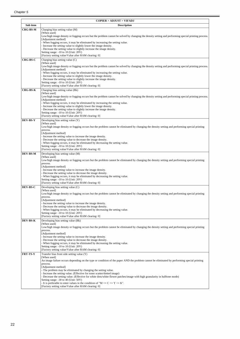
COPIER > ADJUST > VIFADJSub item Description
CRG-BS-Y Charging bias setting value (Y)[When used]Low/high image density or fogging occurs but the problem cannot be solved by changing the density setting and performing special printing process.[Adjustment method]- When fogging occurs, it may be eliminated by increasing the setting value.- Increase the setting value to slightly lower the image density.- Decrease the setting value to slightly increase the image density.Setting range: -10 to 10 (Unit: 20V)[Factory setting value/Value after RAM clearing: 0]
COPIER > ADJUST > CCDSub item Description
Chapter 5
22
CRG-BS-M Charging bias setting value (M)[When used]Low/high image density or fogging occurs but the problem cannot be solved by changing the density setting and performing special printing process.[Adjustment method]- When fogging occurs, it may be eliminated by increasing the setting value.- Increase the setting value to slightly lower the image density.- Decrease the setting value to slightly increase the image density.Setting range: -10 to 10 (Unit: 20V)[Factory setting value/Value after RAM clearing: 0]
CRG-BS-C Charging bias setting value (C)[When used]Low/high image density or fogging occurs but the problem cannot be solved by changing the density setting and performing special printing process.[Adjustment method]- When fogging occurs, it may be eliminated by increasing the setting value.- Increase the setting value to slightly lower the image density.- Decrease the setting value to slightly increase the image density.Setting range: -10 to 10 (Unit: 20V)[Factory setting value/Value after RAM clearing: 0]
CRG-BS-K Charging bias setting value (Bk)[When used]Low/high image density or fogging occurs but the problem cannot be solved by changing the density setting and performing special printing process.[Adjustment method]- When fogging occurs, it may be eliminated by increasing the setting value.- Increase the setting value to slightly lower the image density.- Decrease the setting value to slightly increase the image density.Setting range: -10 to 10 (Unit: 20V)[Factory setting value/Value after RAM clearing: 0]
DEV-BS-Y Developing bias setting value (Y)[When used]Low/high image density or fogging occurs but the problem cannot be eliminated by changing the density setting and performing special printing process.[Adjustment method]- Increase the setting value to increase the image density.- Decrease the setting value to decrease the image density.- When fogging occurs, it may be eliminated by decreasing the setting value.Setting range: -10 to 10 (Unit: 20V)[Factory setting value/Value after RAM clearing: 0]
DEV-BS-M Developing bias setting value (M)[When used]Low/high image density or fogging occurs but the problem cannot be eliminated by changing the density setting and performing special printing process.[Adjustment method]- Increase the setting value to increase the image density.- Decrease the setting value to decrease the image density.- When fogging occurs, it may be eliminated by decreasing the setting value.Setting range: -10 to 10 (Unit: 20V)[Factory setting value/Value after RAM clearing: 0]
DEV-BS-C Developing bias setting value (C)[When used]Low/high image density or fogging occurs but the problem cannot be eliminated by changing the density setting and performing special printing process.[Adjustment method]- Increase the setting value to increase the image density.- Decrease the setting value to decrease the image density.- When fogging occurs, it may be eliminated by decreasing the setting value.Setting range: -10 to 10 (Unit: 20V)[Factory setting value/Value after RAM clearing: 0]
DEV-BS-K Developing bias setting value (Bk)[When used]Low/high image density or fogging occurs but the problem cannot be eliminated by changing the density setting and performing special printing process.[Adjustment method]- Increase the setting value to increase the image density.- Decrease the setting value to decrease the image density.- When fogging occurs, it may be eliminated by decreasing the setting value.Setting range: -10 to 10 (Unit: 20V)[Factory setting value/Value after RAM clearing: 0]
FRT-TS-Y Transfer bias front side setting value (Y)[When used]An image failure occurs depending on the type or condition of the paper AND the problem cannot be eliminated by performing special printing process.[Adjustment method]- The problem may be eliminated by changing the setting value.- Increase the setting value. (Effective for toner scatter/dotted image)- Decrease the setting value. (Effective for white dots/white flower patches/image with high granularity in halftone mode)Setting range: -30 to 40 (Unit: 50V)- It is preferable to enter values in the condition of "M <= C <= Y <= K".[Factory setting value/Value after RAM clearing: 0]
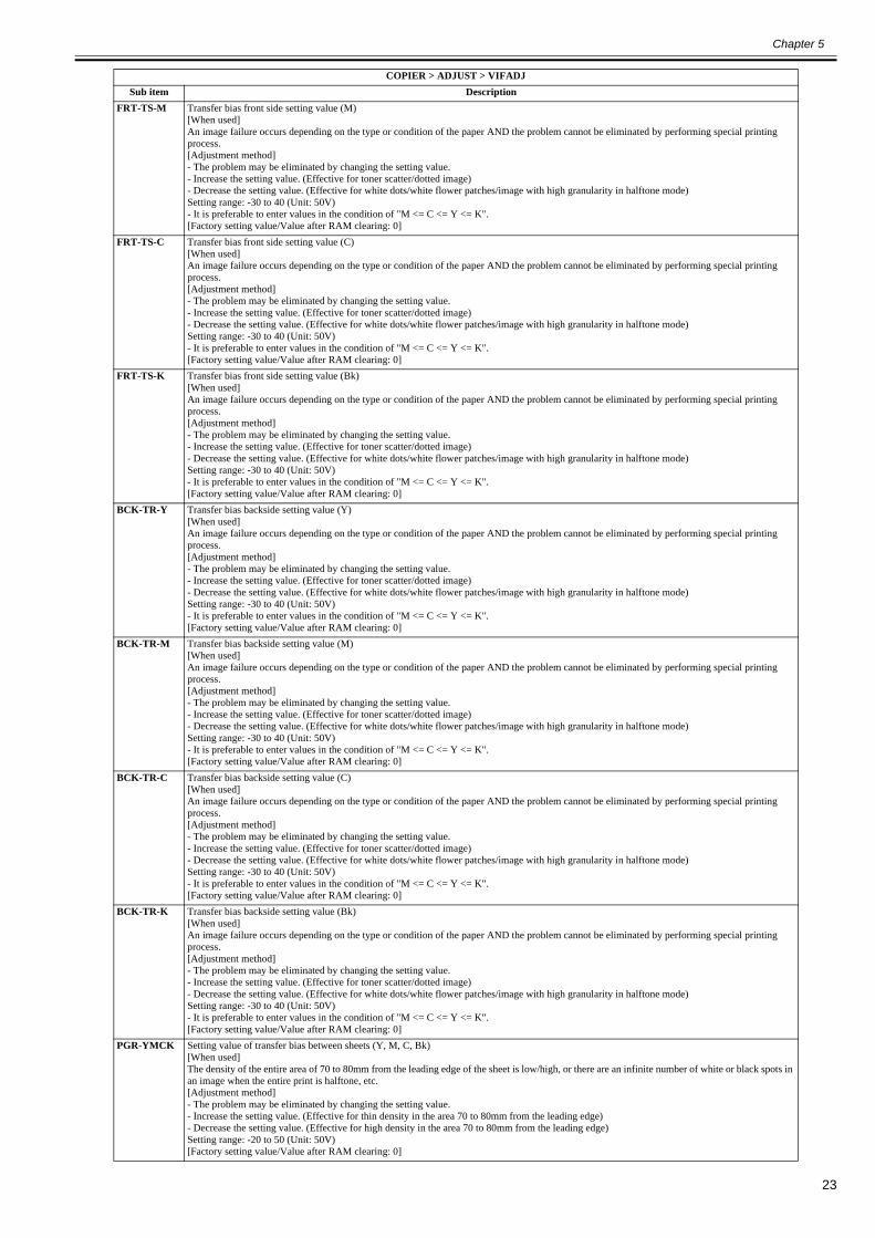
COPIER > ADJUST > VIFADJSub item Description
Chapter 5
23
FRT-TS-M Transfer bias front side setting value (M)[When used]An image failure occurs depending on the type or condition of the paper AND the problem cannot be eliminated by performing special printing process.[Adjustment method]- The problem may be eliminated by changing the setting value.- Increase the setting value. (Effective for toner scatter/dotted image)- Decrease the setting value. (Effective for white dots/white flower patches/image with high granularity in halftone mode)Setting range: -30 to 40 (Unit: 50V)- It is preferable to enter values in the condition of "M <= C <= Y <= K".[Factory setting value/Value after RAM clearing: 0]
FRT-TS-C Transfer bias front side setting value (C)[When used]An image failure occurs depending on the type or condition of the paper AND the problem cannot be eliminated by performing special printing process.[Adjustment method]- The problem may be eliminated by changing the setting value.- Increase the setting value. (Effective for toner scatter/dotted image)- Decrease the setting value. (Effective for white dots/white flower patches/image with high granularity in halftone mode)Setting range: -30 to 40 (Unit: 50V)- It is preferable to enter values in the condition of "M <= C <= Y <= K".[Factory setting value/Value after RAM clearing: 0]
FRT-TS-K Transfer bias front side setting value (Bk)[When used]An image failure occurs depending on the type or condition of the paper AND the problem cannot be eliminated by performing special printing process.[Adjustment method]- The problem may be eliminated by changing the setting value.- Increase the setting value. (Effective for toner scatter/dotted image)- Decrease the setting value. (Effective for white dots/white flower patches/image with high granularity in halftone mode)Setting range: -30 to 40 (Unit: 50V)- It is preferable to enter values in the condition of "M <= C <= Y <= K".[Factory setting value/Value after RAM clearing: 0]
BCK-TR-Y Transfer bias backside setting value (Y)[When used]An image failure occurs depending on the type or condition of the paper AND the problem cannot be eliminated by performing special printing process.[Adjustment method]- The problem may be eliminated by changing the setting value.- Increase the setting value. (Effective for toner scatter/dotted image)- Decrease the setting value. (Effective for white dots/white flower patches/image with high granularity in halftone mode)Setting range: -30 to 40 (Unit: 50V)- It is preferable to enter values in the condition of "M <= C <= Y <= K".[Factory setting value/Value after RAM clearing: 0]
BCK-TR-M Transfer bias backside setting value (M)[When used]An image failure occurs depending on the type or condition of the paper AND the problem cannot be eliminated by performing special printing process.[Adjustment method]- The problem may be eliminated by changing the setting value.- Increase the setting value. (Effective for toner scatter/dotted image)- Decrease the setting value. (Effective for white dots/white flower patches/image with high granularity in halftone mode)Setting range: -30 to 40 (Unit: 50V)- It is preferable to enter values in the condition of "M <= C <= Y <= K".[Factory setting value/Value after RAM clearing: 0]
BCK-TR-C Transfer bias backside setting value (C)[When used]An image failure occurs depending on the type or condition of the paper AND the problem cannot be eliminated by performing special printing process.[Adjustment method]- The problem may be eliminated by changing the setting value.- Increase the setting value. (Effective for toner scatter/dotted image)- Decrease the setting value. (Effective for white dots/white flower patches/image with high granularity in halftone mode)Setting range: -30 to 40 (Unit: 50V)- It is preferable to enter values in the condition of "M <= C <= Y <= K".[Factory setting value/Value after RAM clearing: 0]
BCK-TR-K Transfer bias backside setting value (Bk)[When used]An image failure occurs depending on the type or condition of the paper AND the problem cannot be eliminated by performing special printing process.[Adjustment method]- The problem may be eliminated by changing the setting value.- Increase the setting value. (Effective for toner scatter/dotted image)- Decrease the setting value. (Effective for white dots/white flower patches/image with high granularity in halftone mode)Setting range: -30 to 40 (Unit: 50V)- It is preferable to enter values in the condition of "M <= C <= Y <= K".[Factory setting value/Value after RAM clearing: 0]
PGR-YMCK Setting value of transfer bias between sheets (Y, M, C, Bk)[When used]The density of the entire area of 70 to 80mm from the leading edge of the sheet is low/high, or there are an infinite number of white or black spots in an image when the entire print is halftone, etc.[Adjustment method]- The problem may be eliminated by changing the setting value.- Increase the setting value. (Effective for thin density in the area 70 to 80mm from the leading edge)- Decrease the setting value. (Effective for high density in the area 70 to 80mm from the leading edge)Setting range: -20 to 50 (Unit: 50V)[Factory setting value/Value after RAM clearing: 0]
COPIER > ADJUST > VIFADJSub item Description

Chapter 5
24
5.1.4 FUNCTION
5.1.4.1 FUNCTION List0020-2015
i-SENSYS MF9170 / i-SENSYS MF9130 / i-SENSYS MF8450
<INSTALL>T-5-9
FRT-ATH Attraction bias front side setting value[When used]An image failure occurs depending on the type or condition of the paper AND the problem cannot be eliminated by performing special printing process.[Adjustment method]- The problem may be eliminated by changing the setting value.Setting range: -20 to 20 (Unit: 100V)[Factory setting value/Value after RAM clearing: 0]
BCK-ATH Attraction bias backside setting value[When used]An image failure occurs depending on the type or condition of the paper AND the problem cannot be eliminated by performing special printing process.[Adjustment method]- The problem may be eliminated by changing the setting value.Setting range: -20 to 20 (Unit: 100V)[Factory setting value/Value after RAM clearing: 0]
FRFS-TMP Fixing temperature front side setting value[When used]The problem cannot be eliminated by performing special printing process and the image is not firmly fixed to the sheet, or a residual image remains in the image.[Caution] The fixing heater temperature is changed via this mode, and therefore, attentions should be paid when using this mode.[Adjustment method]- When an image is not firmly fixed to the sheet, the problem may be eliminated by increasing the setting value.- When a residual image remains in an image, the problem may be eliminated by decreasing the setting value.Setting range: -4 to 4 (Unit: Approx. 5 degree C)[Factory setting value/Value after RAM clearing: 0]
BKFS-TMP Fixing temperature backside setting value[When used]The problem cannot be eliminated by performing special printing process and the image is not firmly fixed to the sheet, or a residual image remains in the image.[Caution] The fixing heater temperature is changed via this mode, and therefore, attentions should be paid when using this mode.[Adjustment method]- When an image is not firmly fixed to the sheet, the problem may be eliminated by increasing the setting value.- When a residual image remains in an image, the problem may be eliminated by decreasing the setting value.Setting range: -4 to 4 (Unit: Approx. 5 degree C)[Factory setting value/Value after RAM clearing: 0]
COPIER > FUNCTION > INSTALLSub item Description
CARD Not usedE-RDS Enabling/disabling of the e-RDS function
Setting value: 0: Disabled, 1: Enabled[Factory setting value/Value after RAM clearing: 0]
RGW-PORT Setting of the port number of the sales company's server used for E-RDSRefer to the port number in the user mode.Setting range: 1 to 65535[Factory setting value/Value after RAM clearing: 443]
COM-TEST Confirmation of the connection with the sales company's server used for E-RDSTry to connect the sales company's server. Make a judgment of whether connection has been made or not, and display the result by OK or NG.
COM-LOG Display of a communication error logDisplay the detailed result of communication test with the sales company's server used for E-RDS.When an error occurs in communication with the sales company's server, error information is displayed.<Log contents>Number: No. 1 is assigned to the latest one.Error code: 8-digit hexadecimal numberDate: Date when the error occurredTime: Time when the error occurredDetailed error information: 128 characters maximum5 logs maximum
RGW-ADR Setting of the URL of the sales company's server used for E-RDSSet the URL of the sales company's server.Setting value: URL (incl. NULL, SJIS is not supported) (128 characters maximum)
CNT-DATE Setting of the date and time to start sending counter information to the serverSet the date and time to start sending counter information to the server using the E-RDS third-party extended function.Refer to the date and time setting in the user mode.
(12 digits: YYYYMMDDHHMM)YYYY: Year, MM: Month, DD: Day, HH: Hour, MM: Minute)
Setting range: 2000/1/1 00:00 to 2037/12/31 23.59[Factory setting value/Value after RAM clearing: 000000000000]
CNT-INTV Setting of the interval for sending counter information to the serverSet the interval of sending counter information to the server using the E-RDS third-party extended function.Setting range: 1 to 168 (Unit: 1 week)[Factory setting value/Value after RAM clearing: 24]
COPIER > ADJUST > VIFADJSub item Description

Chapter 5
25
<ATTRACT>Not used<DPC>Not used<CST>Not used<CLEANING>Not used<FIXING>Not used<PANEL>
T-5-10
<PART-CHK>Not used<CLEAR>
T-5-11
STRD-POS Automatic detection of the DF stream reading CCD reading positionExecute this item after performing any of the replacement of the ADF unit, replacement of the reader unit, or RAM clearing for the scanner.[Operation]Å@The reading position is adjusted while the scanner continues to move by 0.1 mm.[Time]Å@When the lamp lights up: Adjustment time: 10 sec When the lamp does not light up: Lamp adjustment time of 10 to 30 sec + Adjustment time of 10 sec[Displays]0: Operating / 1: OK / 2: NG
COPIER > FUNCTION > PANELSub item Description
LCD-CHK Not usedLED-CHK Not usedLED-OFF Not usedKEY-CHK Not used
COPIER > FUNCTION > CLEARSub item Description
R-CON Not usedTEL-USER Clearing of user data and data registered in the address book
SSSW is not cleared.SRVC-DAT Clearing of SERVICE DATA
User data is not cleared.COUNTER Clearing of the maintenance/parts counter and mode counter to 0
Clear the counter (numerator) on the system dump list to 0.TYPE Initialization of USER DATA and SERVICE DATA for the specified destination setting
Japan: JAPANUSA: U.S.A.Europe: EUROPE 1(area) / U.K. / SWEDEN / SWISS / AUSTRIA / DENMARK / NORWAY / HOLLAND / BERUGIUM / FINLAND / ITALY / SPAIN / PORTUGAL / IRELAND / HUNGARY / SAF / GERMANY / FRANCE / CZECH / SLOVENIA / PORLAND / GREECE/ LUXEMBOURG / RUSSIA / EUROPE 2(area)Australia: AUSTRALIA / N.Z.China: CHINAKorea: KOREATaiwan: TAIWANAsia: SINGAPORE / HONG KONG / MALAYSIA / ASIA(area)
Note) STANDARD / CANADA are not in use.
HIST ACT-HIST Clearing of the communication management historyACC-HIST Clearing of the print historyJAM-HIST Clearing of the jam historyERR-HIST Clearing of the error (E code) historyALARM Not usedENV-HIST Not used
CARD Clearing of the connection information of a new card reader equipmentClear data related to card IDs (department).Operation method1) Set the department management in user registration to OFF.2) Execute this item.3) Execute COPIER>FUNCTION>CLEAR>ERR>E719.4) Turn off the main power switch.5) Remove the control card equipment.6) Turn on the main power switch.
ERR E355-CLR Clearing of E355E719-CLR Clearing of E719
Clear the connection information of the control card equipment and coin robo.PWD-CLR Clearing of the password of a system administratorFILE-SYS Initialization of the file system for the main and optional ROMs (File decompression)
COPIER > FUNCTION > INSTALLSub item Description
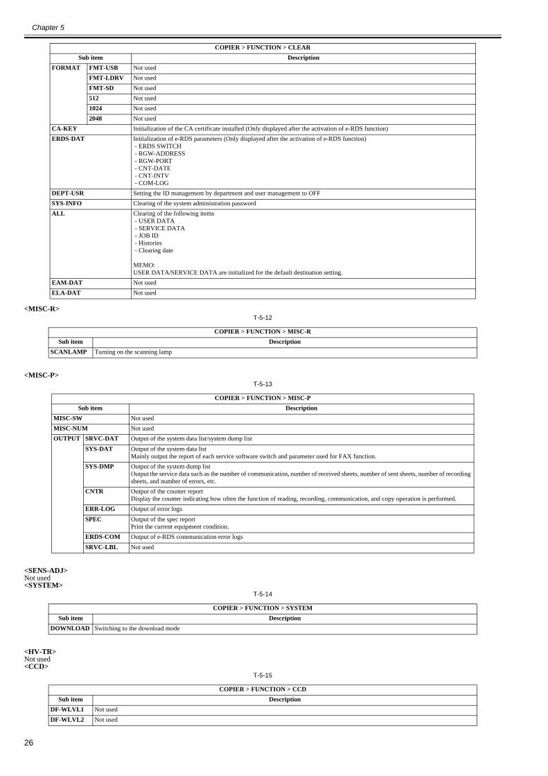
Chapter 5
26
<MISC-R>T-5-12
<MISC-P>T-5-13
<SENS-ADJ>Not used<SYSTEM>
T-5-14
<HV-TR>Not used<CCD>
T-5-15
FORMAT FMT-USB Not usedFMT-LDRV Not usedFMT-SD Not used512 Not used1024 Not used2048 Not used
CA-KEY Initialization of the CA certificate installed (Only displayed after the activation of e-RDS function)ERDS-DAT Initialization of e-RDS parameters (Only displayed after the activation of e-RDS function)
- ERDS SWITCH - RGW-ADDRESS - RGW-PORT - CNT-DATE - CNT-INTV - COM-LOG
DEPT-USR Setting the ID management by department and user management to OFFSYS-INFO Clearing of the system administration passwordALL Clearing of the following items
- USER DATA - SERVICE DATA - JOB ID - Histories - Clearing date
MEMO:USER DATA/SERVICE DATA are initialized for the default destination setting.
EAM-DAT Not usedELA-DAT Not used
COPIER > FUNCTION > MISC-RSub item Description
SCANLAMP Turning on the scanning lamp
COPIER > FUNCTION > MISC-PSub item Description
MISC-SW Not usedMISC-NUM Not usedOUTPUT SRVC-DAT Output of the system data list/system dump list
SYS-DAT Output of the system data listMainly output the report of each service software switch and parameter used for FAX function.
SYS-DMP Output of the system dump listOutput the service data such as the number of communication, number of received sheets, number of sent sheets, number of recording sheets, and number of errors, etc.
CNTR Output of the counter reportDisplay the counter indicating how often the function of reading, recording, communication, and copy operation is performed.
ERR-LOG Output of error logsSPEC Output of the spec report
Print the current equipment condition.ERDS-COM Output of e-RDS communication error logsSRVC-LBL Not used
COPIER > FUNCTION > SYSTEMSub item Description
DOWNLOAD Switching to the download mode
COPIER > FUNCTION > CCDSub item Description
DF-WLVL1 Not usedDF-WLVL2 Not used
COPIER > FUNCTION > CLEARSub item Description
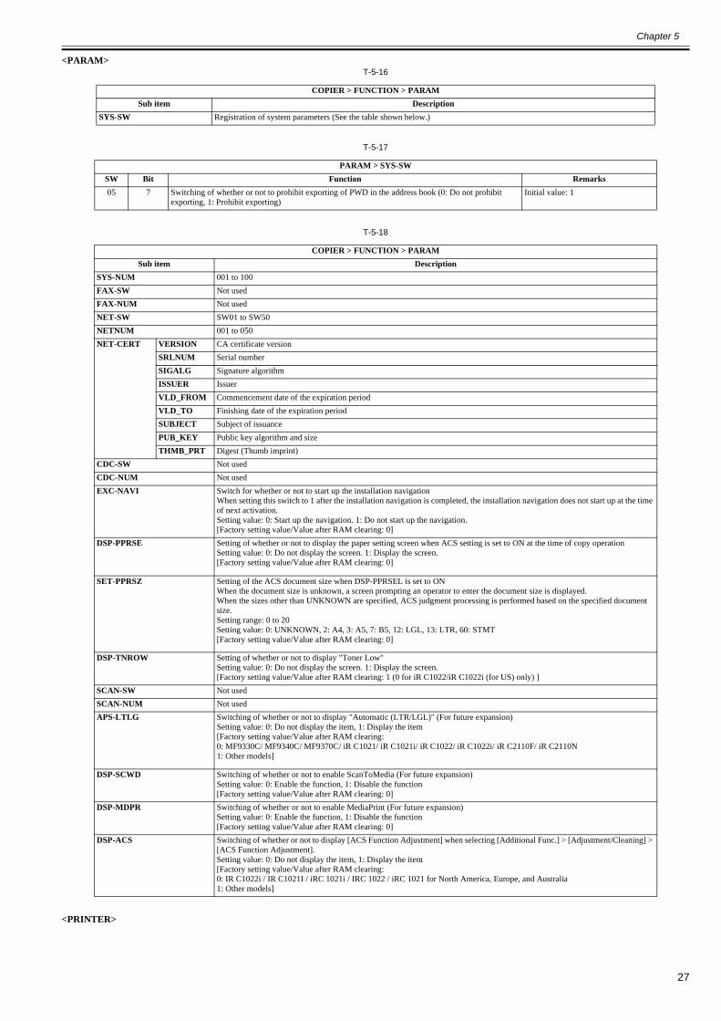
Chapter 5
27
<PARAM>T-5-16
T-5-17
T-5-18
<PRINTER>
COPIER > FUNCTION > PARAMSub item Description
SYS-SW Registration of system parameters (See the table shown below.)
PARAM > SYS-SWSW Bit Function Remarks05 7 Switching of whether or not to prohibit exporting of PWD in the address book (0: Do not prohibit
exporting, 1: Prohibit exporting)Initial value: 1
COPIER > FUNCTION > PARAMSub item Description
SYS-NUM 001 to 100FAX-SW Not usedFAX-NUM Not usedNET-SW SW01 to SW50NETNUM 001 to 050NET-CERT VERSION CA certificate version
SRLNUM Serial numberSIGALG Signature algorithmISSUER IssuerVLD_FROM Commencement date of the expiration periodVLD_TO Finishing date of the expiration periodSUBJECT Subject of issuancePUB_KEY Public key algorithm and sizeTHMB_PRT Digest (Thumb imprint)
CDC-SW Not usedCDC-NUM Not usedEXC-NAVI Switch for whether or not to start up the installation navigation
When setting this switch to 1 after the installation navigation is completed, the installation navigation does not start up at the time of next activation.Setting value: 0: Start up the navigation. 1: Do not start up the navigation.[Factory setting value/Value after RAM clearing: 0]
DSP-PPRSE Setting of whether or not to display the paper setting screen when ACS setting is set to ON at the time of copy operationSetting value: 0: Do not display the screen. 1: Display the screen.[Factory setting value/Value after RAM clearing: 0]
SET-PPRSZ Setting of the ACS document size when DSP-PPRSEL is set to ONWhen the document size is unknown, a screen prompting an operator to enter the document size is displayed.When the sizes other than UNKNOWN are specified, ACS judgment processing is performed based on the specified document size.Setting range: 0 to 20Setting value: 0: UNKNOWN, 2: A4, 3: A5, 7: B5, 12: LGL, 13: LTR, 60: STMT[Factory setting value/Value after RAM clearing: 0]
DSP-TNROW Setting of whether or not to display "Toner Low"Setting value: 0: Do not display the screen. 1: Display the screen.[Factory setting value/Value after RAM clearing: 1 (0 for iR C1022/iR C1022i (for US) only) ]
SCAN-SW Not usedSCAN-NUM Not usedAPS-LTLG Switching of whether or not to display "Automatic (LTR/LGL)" (For future expansion)
Setting value: 0: Do not display the item, 1: Display the item[Factory setting value/Value after RAM clearing:0: MF9330C/ MF9340C/ MF9370C/ iR C1021/ iR C1021i/ iR C1022/ iR C1022i/ iR C2110F/ iR C2110N1: Other models]
DSP-SCWD Switching of whether or not to enable ScanToMedia (For future expansion)Setting value: 0: Enable the function, 1: Disable the function[Factory setting value/Value after RAM clearing: 0]
DSP-MDPR Switching of whether or not to enable MediaPrint (For future expansion)Setting value: 0: Enable the function, 1: Disable the function[Factory setting value/Value after RAM clearing: 0]
DSP-ACS Switching of whether or not to display [ACS Function Adjustment] when selecting [Additional Func.] > [Adjustment/Cleaning] > [ACS Function Adjustment].Setting value: 0: Do not display the item, 1: Display the item[Factory setting value/Value after RAM clearing:0: IR C1022i / IR C1021I / iRC 1021i / IRC 1022 / iRC 1021 for North America, Europe, and Australia1: Other models]

Chapter 5
28
T-5-19
<VIFFNC>T-5-20
<SPLMAN>T-5-21
COPIER > FUNCTION > PRINTERSub item Description
SYS-SW Not usedSYS-NUM Not used
COPIER > FUNCTION > VIFFNCSub item Description
RSTR-DCN Restoration of the backup information of DC controller NVRAM retained in the controller's NVRAM to the DC controller NVRAMPerform the following procedure after replacement of the DC controller PCB.1) Using this item, restore the backup data of the DC controller retained in the NVRAM of the main controller PCB to the NVRAM of the DC controller PCB.2) Print the user data list by selecting "Initial setting/registration > Report output > List print > User data list".3) Execute full correction by selecting "Initial setting/registration > Adjustment > Cleaning > Automatic gradation correction > Full correction".
CLR-DCN Clear of the backup information of DC controller NVRAM retained in the controller's NVRAM to the DC controller NVRAMSEL-TALC Setting of TALC paper
ETB cleaning is performed 10 times at initial rotation.INV-ATVC Setting to enable ATVC
Ignore ATVC and use a default value for the output value of each bias.IMP-BNDG Setting for banding improvement
Perform idling with engagement of the developing assembly and disengagement of ETB.AANY-0 / AANY-1
Setting of any-any mode 0 / any-any mode 1
Combination of any-any mode 0 / any-any mode 1AANY-0=0/AANY-1=0: Perform constant-speed cleaning after a job only when the paper size does not match.AANY-0=1/AANY-1=0: Perform high-speed cleaning after all jobs.AANY-0=0/AANY-1=1: Perform constant-speed cleaning after all jobs.AANY-0=1/AANY-1=1: Perform high-speed cleaning after a job only when the paper size does not match.
COPIER > FUNCTION > SPLMANSub item Description
SPL27767 Setting of high-resistance paperDecrease the final output value of transfer bias by 250V.(Only when high-humidity OHT/high-humidity gloss film is not specified)Setting value: 0: OFF, 1: ON[Factory setting value/Value after RAM clearing: 0]
SPL27267 Setting of 4mil OHTDecrease the final output value of transfer bias by 500V.(Only when high-humidity OHT/high-humidity gloss film/high-resistance paper is not specified)Setting value: 0: OFF, 1: ON[Factory setting value/Value after RAM clearing: 0]
SPL23866 Setting of calcium carbonate paperApply the maximum attraction bias wherever possible regardless of the environment. Since there is no result of detection of attraction paper resistance, set a transfer bias from the environment.Setting value: 0: OFF, 1: ON[Factory setting value/Value after RAM clearing: 0]
SPL25407 Setting of thin paper/rough paperChange the process speed to 4/5 speed. Use the temperature control table for thin paper/rough paper. (Thin paper only)Do not change the process speed, but change the temperature control table. (Plain paper, Thick paper 2 only)Setting value: 0: OFF, 1: ON[Factory setting value/Value after RAM clearing: 0]
SPL47267 Setting of high-humidity OHTDecrease the final output value of transfer bias by 100V. (OHT only)Setting value: 0: OFF, 1: ON[Factory setting value/Value after RAM clearing: 0]
SPL47667 Setting of prevention of re-transferDecrease the transfer bias for the 3rd/4th station depending on the environment.(Only when high-humidity OHT/high-humidity gloss film/high-resistance paper/4mil OHT is not specified)Setting value: 0: OFF, 1: ON[Factory setting value/Value after RAM clearing: 0]
SPL34691 Setting for improvement of color misregistrationRotate the fixing motor in +0.5% speed up to the 10th page. Secure the wait time of 10 seconds when the 1st page is picked up at the time of initial rotation, mode switching, or toner ejection.Setting value: 0: OFF, 1: ON[Factory setting value/Value after RAM clearing: 0]
SPL14682 Setting for prevention of fogging 2Turn off the pre-exposure operation. Do not add a transfer bias as measures to prevent a bird's foot print on the trailing edge.Setting value: 0: OFF, 1: ON[Factory setting value/Value after RAM clearing: 0]
SPL25200 Setting for improvement of OHT transparencySet the controlled temperature at 180 degC, and perform idling of the fixing machine for 45 seconds before initial rotation.Setting value: 0: OFF, 1: ON[Factory setting value/Value after RAM clearing: 0]
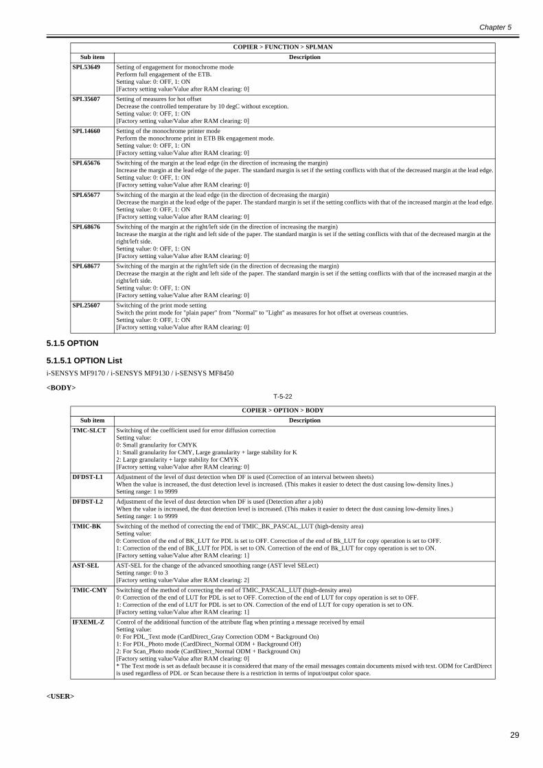
Chapter 5
29
5.1.5 OPTION
5.1.5.1 OPTION List0020-2016
i-SENSYS MF9170 / i-SENSYS MF9130 / i-SENSYS MF8450
<BODY>T-5-22
<USER>
SPL53649 Setting of engagement for monochrome modePerform full engagement of the ETB.Setting value: 0: OFF, 1: ON[Factory setting value/Value after RAM clearing: 0]
SPL35607 Setting of measures for hot offsetDecrease the controlled temperature by 10 degC without exception.Setting value: 0: OFF, 1: ON[Factory setting value/Value after RAM clearing: 0]
SPL14660 Setting of the monochrome printer modePerform the monochrome print in ETB Bk engagement mode.Setting value: 0: OFF, 1: ON[Factory setting value/Value after RAM clearing: 0]
SPL65676 Switching of the margin at the lead edge (in the direction of increasing the margin)Increase the margin at the lead edge of the paper. The standard margin is set if the setting conflicts with that of the decreased margin at the lead edge.Setting value: 0: OFF, 1: ON[Factory setting value/Value after RAM clearing: 0]
SPL65677 Switching of the margin at the lead edge (in the direction of decreasing the margin)Decrease the margin at the lead edge of the paper. The standard margin is set if the setting conflicts with that of the increased margin at the lead edge.Setting value: 0: OFF, 1: ON[Factory setting value/Value after RAM clearing: 0]
SPL68676 Switching of the margin at the right/left side (in the direction of increasing the margin)Increase the margin at the right and left side of the paper. The standard margin is set if the setting conflicts with that of the decreased margin at the right/left side.Setting value: 0: OFF, 1: ON[Factory setting value/Value after RAM clearing: 0]
SPL68677 Switching of the margin at the right/left side (in the direction of decreasing the margin)Decrease the margin at the right and left side of the paper. The standard margin is set if the setting conflicts with that of the increased margin at the right/left side.Setting value: 0: OFF, 1: ON[Factory setting value/Value after RAM clearing: 0]
SPL25607 Switching of the print mode settingSwitch the print mode for "plain paper" from "Normal" to "Light" as measures for hot offset at overseas countries.Setting value: 0: OFF, 1: ON[Factory setting value/Value after RAM clearing: 0]
COPIER > OPTION > BODYSub item Description
TMC-SLCT Switching of the coefficient used for error diffusion correctionSetting value:0: Small granularity for CMYK1: Small granularity for CMY, Large granularity + large stability for K2: Large granularity + large stability for CMYK[Factory setting value/Value after RAM clearing: 0]
DFDST-L1 Adjustment of the level of dust detection when DF is used (Correction of an interval between sheets)When the value is increased, the dust detection level is increased. (This makes it easier to detect the dust causing low-density lines.)Setting range: 1 to 9999
DFDST-L2 Adjustment of the level of dust detection when DF is used (Detection after a job)When the value is increased, the dust detection level is increased. (This makes it easier to detect the dust causing low-density lines.)Setting range: 1 to 9999
TMIC-BK Switching of the method of correcting the end of TMIC_BK_PASCAL_LUT (high-density area)Setting value:0: Correction of the end of BK_LUT for PDL is set to OFF. Correction of the end of Bk_LUT for copy operation is set to OFF.1: Correction of the end of BK_LUT for PDL is set to ON. Correction of the end of Bk_LUT for copy operation is set to ON.[Factory setting value/Value after RAM clearing: 1]
AST-SEL AST-SEL for the change of the advanced smoothing range (AST level SELect)Setting range: 0 to 3[Factory setting value/Value after RAM clearing: 2]
TMIC-CMY Switching of the method of correcting the end of TMIC_PASCAL_LUT (high-density area)0: Correction of the end of LUT for PDL is set to OFF. Correction of the end of LUT for copy operation is set to OFF.1: Correction of the end of LUT for PDL is set to ON. Correction of the end of LUT for copy operation is set to ON.[Factory setting value/Value after RAM clearing: 1]
IFXEML-Z Control of the additional function of the attribute flag when printing a message received by emailSetting value:0: For PDL_Text mode (CardDirect_Gray Correction ODM + Background On)1: For PDL_Photo mode (CardDirect_Normal ODM + Background Off)2: For Scan_Photo mode (CardDirect_Normal ODM + Background On)[Factory setting value/Value after RAM clearing: 0]* The Text mode is set as default because it is considered that many of the email messages contain documents mixed with text. ODM for CardDirect is used regardless of PDL or Scan because there is a restriction in terms of input/output color space.
COPIER > FUNCTION > SPLMANSub item Description

Chapter 5
30
T-5-23
Software counter specifications100 to 199: Total200 to 299: Copy (When more numbers are needed, add the number from 001.)300 to 399: Print400 to 499: Copy and print500 to 599: Scan600 to 699: Box, Media/Pic/Mobile phone print700 to 799: Reception print800 to 899: Report print900 to 999: Sending/Box/Remote/Media
<Explanation of the symbols in the table>- yes: Valid counter for this machine
- Large size: Paper larger than B4-size- Small size: B4-size or smaller paper- Numbers 1, 2 indicated under "Counter Details": Number of counts for large size paper- Total A: Total number of counts for operation other than "local copy + remote copy"- Total B: Total number of counts for operation other than "local copy + remote copy + Box print"- Copy: Local copy + remote copy + Box print- Copy A: Local copy + remote copy + Box print- Print: PDL print + report print + Box print- Print A: PDL print + report print- Scan: B&W scan + color scan
T-5-24
COPIER > OPTION > USERSub item Description
COUNTER1 Selection of the counter type for Counter 1[Factory setting value/Value after RAM clearing: 101 (The settings cannot be changed; display only. (Reference: External and Controls > Counters) ]
COUNTER2 Selection of the counter type for Counter 2Setting range: 0 to 999[Factory setting value/Value after RAM clearing: (Reference: External and Controls > Counters)]
COUNTER3 Selection of the counter type for Counter 3Setting range: 0 to 999[Factory setting value/Value after RAM clearing: (Reference: External and Controls > Counters)]
COUNTER4 Selection of the counter type for Counter 4Setting range: 0 to 999[Factory setting value/Value after RAM clearing: (Reference: External and Controls > Counters)]
COUNTER5 Selection of the counter type for Counter 5Setting range: 0 to 999[Factory setting value/Value after RAM clearing: (Reference: External and Controls > Counters)]
COUNTER6 Selection of the counter type for Counter 6Setting range: 0 to 999[Factory setting value/Value after RAM clearing: (Reference: External and Controls > Counters)]
TNRB-SW Switching of whether or not to display the toner bottle counterSetting value: 0: Do not display the toner bottle counter. 1: Display the toner bottle counter.[Factory setting value/Value after RAM clearing: 0]
CNT-SW Switching of the type of counter displaySetting range: 0 to 4[Factory setting value/Value after RAM clearing: 0]
SCALL-SW Turning ON/OFF call button functionSetting value: 0: Call button function OFF 1: Call button function ON [Factory setting value/Value after RAM clearing: 0]
SCALLCMP Actions when repair of call button function is completedUsed when actions for a repair request are completed.
Numbers from 191 to 194 are not available for the settings of Counter 2 to 6.
Compatibility No. Counter descriptionyes 101 Total 1yes 102 Total 2
103 Total (large)yes 104 Total (small)yes 105 Total (full-color 1)yes 106 Total (full-color 2)yes 108 Total (black and white 1)yes 109 Total (black and white 2)
110 Total (monocolor/large)111 Total (monocolor/small)112 Total (black and white/large)
yes 113 Total (black and white/small)yes 114 Total 1 (two-sided)yes 115 Total 2 (two-sided)

Chapter 5
31
116 Large (two-sided)yes 117 Small (two-sided)
118 Total (monocolor 1)119 Total (monocolor 2)120 Total (full-color/large)
yes 121 Total (full-color/small)122 Total (full-color + monocolor/large)
yes 123 Total (full-color + monocolor/small)yes 124 Total (full-color + monocolor 2)yes 125 Total (full-color + monocolor 1)yes 126 Total A1yes 127 Total A2
128 Total A (large)yes 129 Total A (small)yes 130 Total A (full color 1)yes 131 Total A (full color 2)yes 132 Total A (black and white 1)yes 133 Total A (black and white 2)
134 Total A (mono color /large)135 Total A (mono color /small)136 Total A (black and white /large)
yes 137 Total A (black and white /small)yes 138 Total A 1(double sided)yes 139 Total A 2(double sided)
140 large A (double sided)yes 141 small A (double sided)
142 Total A (mono color 1)143 Total A (mono color 2)144 Total A (full color /large )
yes 145 Total A (full color /small)146 Total A (full color +mono color /large )
yes 147 Total A (full color +mono color /small)yes 148 Total A (full color +mono color 2)yes 149 Total A (full color +mono color 1)yes 150 Total B1yes 151 Total B2
152 Total B (large)yes 153 Total B (small)yes 154 Total B (full color 1)yes 155 Total B (full color 2)yes 156 Total B (black and white 1)yes 157 Total B (black and white 2)
158 Total B (mono color /large)159 Total B (mono color /small)160 Total B (black and white /large)
yes 161 Total B (black and white /small)yes 162 Total B1 (double sided)yes 163 Total B2 (double sided)
164 large B (double sided)yes 165 small B (double sided)
166 Total B (mono color 1)167 Total B (mono color 2)168 Total B (full color /large )
yes 169 Total B (full color /small)170 Total B (full color +mono color /large )
yes 171 Total B (full color +mono color /small)yes 172 Total B (full color +mono color 2)yes 173 Total B (full color +mono color 1)yes 191 Toner replacement / yellowyes 192 Toner replacement / magentayes 193 Toner replacement / cyanyes 194 Toner replacement / black
195 Toner replacement / expansion 1196 Toner replacement / expansion 2
yes 201 Copies (total 1)yes 202 Copies (total 2)
Compatibility No. Counter description
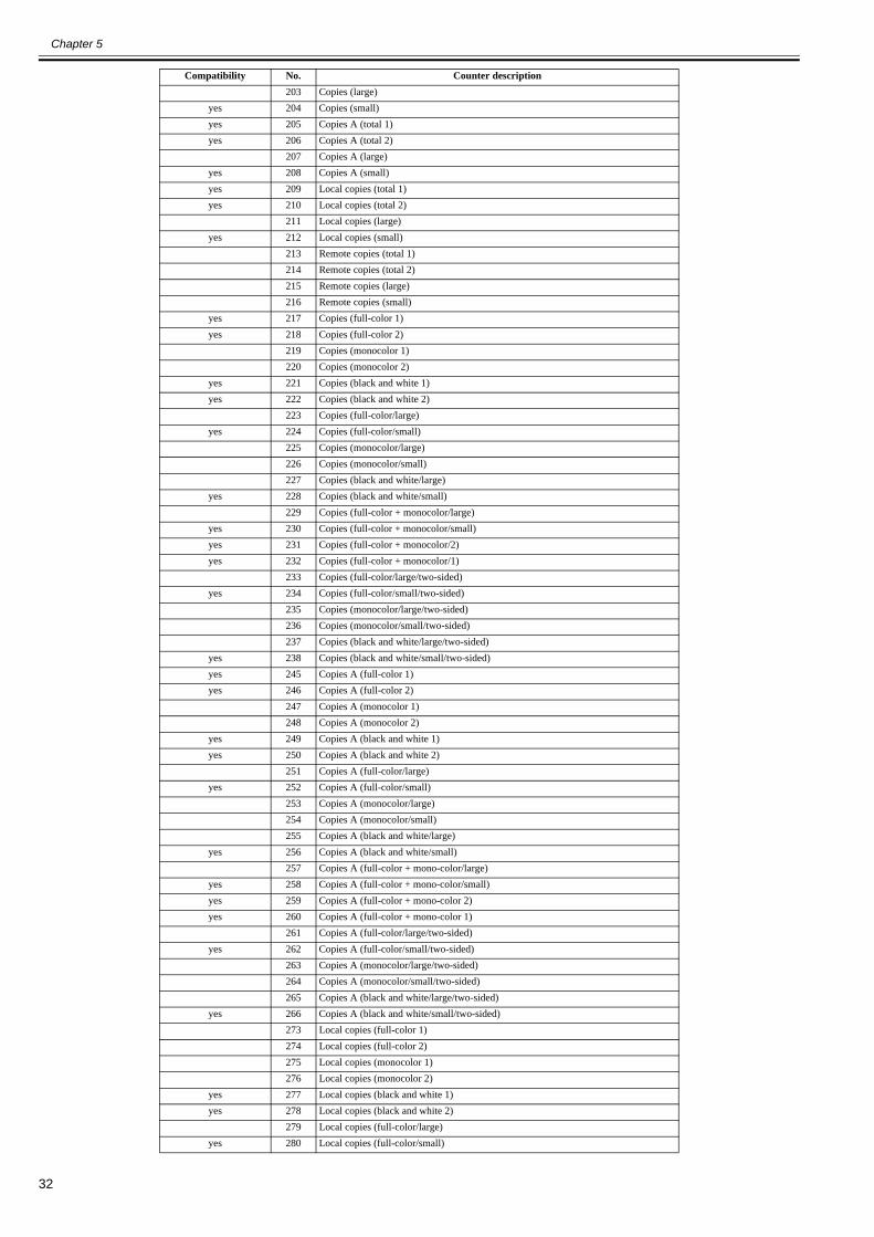
Chapter 5
32
203 Copies (large)yes 204 Copies (small)yes 205 Copies A (total 1) yes 206 Copies A (total 2)
207 Copies A (large)yes 208 Copies A (small)yes 209 Local copies (total 1)yes 210 Local copies (total 2)
211 Local copies (large)yes 212 Local copies (small)
213 Remote copies (total 1)214 Remote copies (total 2)215 Remote copies (large)216 Remote copies (small)
yes 217 Copies (full-color 1)yes 218 Copies (full-color 2)
219 Copies (monocolor 1)220 Copies (monocolor 2)
yes 221 Copies (black and white 1)yes 222 Copies (black and white 2)
223 Copies (full-color/large)yes 224 Copies (full-color/small)
225 Copies (monocolor/large)226 Copies (monocolor/small)227 Copies (black and white/large)
yes 228 Copies (black and white/small)229 Copies (full-color + monocolor/large)
yes 230 Copies (full-color + monocolor/small)yes 231 Copies (full-color + monocolor/2)yes 232 Copies (full-color + monocolor/1)
233 Copies (full-color/large/two-sided)yes 234 Copies (full-color/small/two-sided)
235 Copies (monocolor/large/two-sided)236 Copies (monocolor/small/two-sided)237 Copies (black and white/large/two-sided)
yes 238 Copies (black and white/small/two-sided)yes 245 Copies A (full-color 1)yes 246 Copies A (full-color 2)
247 Copies A (monocolor 1)248 Copies A (monocolor 2)
yes 249 Copies A (black and white 1)yes 250 Copies A (black and white 2)
251 Copies A (full-color/large)yes 252 Copies A (full-color/small)
253 Copies A (monocolor/large)254 Copies A (monocolor/small)255 Copies A (black and white/large)
yes 256 Copies A (black and white/small)257 Copies A (full-color + mono-color/large)
yes 258 Copies A (full-color + mono-color/small)yes 259 Copies A (full-color + mono-color 2)yes 260 Copies A (full-color + mono-color 1)
261 Copies A (full-color/large/two-sided)yes 262 Copies A (full-color/small/two-sided)
263 Copies A (monocolor/large/two-sided)264 Copies A (monocolor/small/two-sided)265 Copies A (black and white/large/two-sided)
yes 266 Copies A (black and white/small/two-sided)273 Local copies (full-color 1)274 Local copies (full-color 2)275 Local copies (monocolor 1)276 Local copies (monocolor 2)
yes 277 Local copies (black and white 1)yes 278 Local copies (black and white 2)
279 Local copies (full-color/large)yes 280 Local copies (full-color/small)
Compatibility No. Counter description
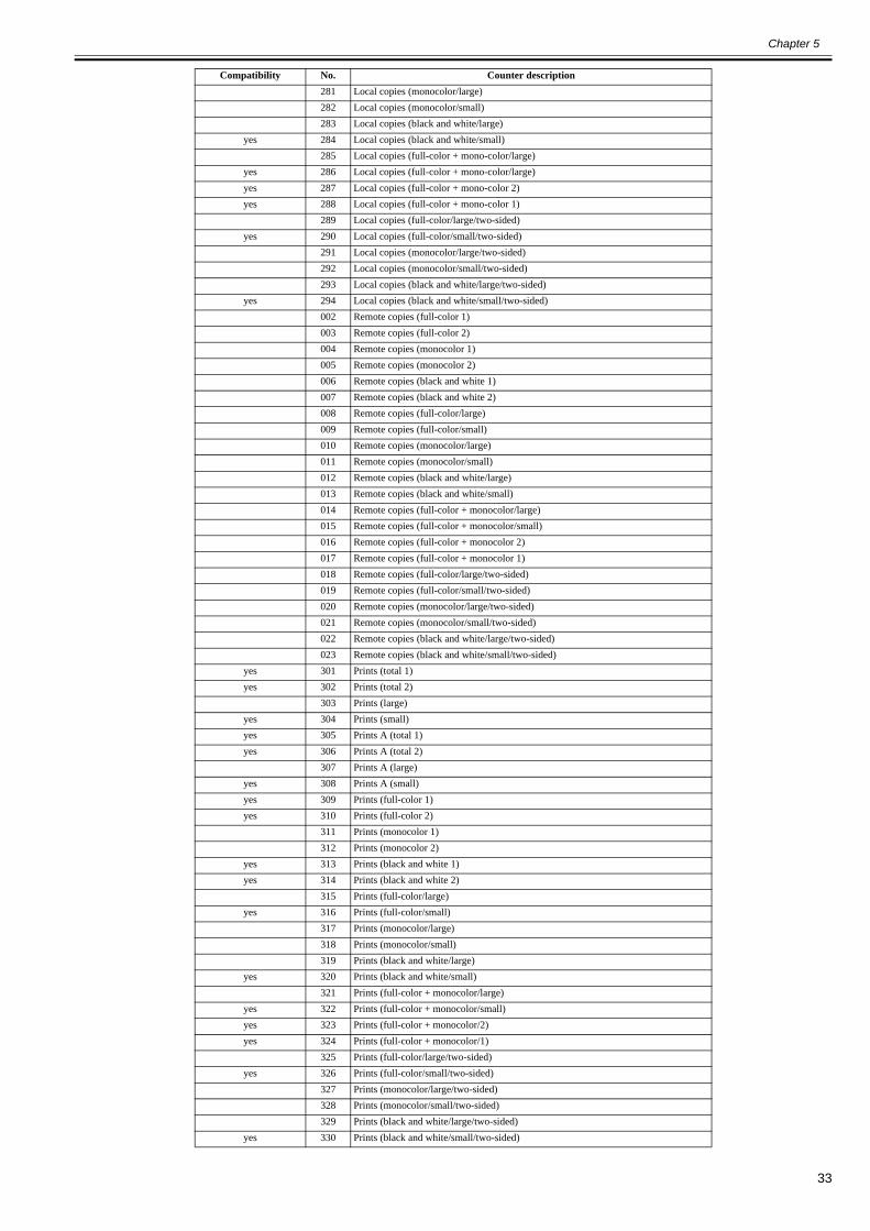
Chapter 5
33
281 Local copies (monocolor/large)282 Local copies (monocolor/small)283 Local copies (black and white/large)
yes 284 Local copies (black and white/small)285 Local copies (full-color + mono-color/large)
yes 286 Local copies (full-color + mono-color/large)yes 287 Local copies (full-color + mono-color 2)yes 288 Local copies (full-color + mono-color 1)
289 Local copies (full-color/large/two-sided)yes 290 Local copies (full-color/small/two-sided)
291 Local copies (monocolor/large/two-sided)292 Local copies (monocolor/small/two-sided)293 Local copies (black and white/large/two-sided)
yes 294 Local copies (black and white/small/two-sided)002 Remote copies (full-color 1)003 Remote copies (full-color 2)004 Remote copies (monocolor 1)005 Remote copies (monocolor 2)006 Remote copies (black and white 1)007 Remote copies (black and white 2)008 Remote copies (full-color/large) 009 Remote copies (full-color/small)010 Remote copies (monocolor/large)011 Remote copies (monocolor/small)012 Remote copies (black and white/large)013 Remote copies (black and white/small)014 Remote copies (full-color + monocolor/large)015 Remote copies (full-color + monocolor/small)016 Remote copies (full-color + monocolor 2)017 Remote copies (full-color + monocolor 1)018 Remote copies (full-color/large/two-sided)019 Remote copies (full-color/small/two-sided)020 Remote copies (monocolor/large/two-sided)021 Remote copies (monocolor/small/two-sided)022 Remote copies (black and white/large/two-sided)023 Remote copies (black and white/small/two-sided)
yes 301 Prints (total 1) yes 302 Prints (total 2)
303 Prints (large)yes 304 Prints (small)yes 305 Prints A (total 1)yes 306 Prints A (total 2)
307 Prints A (large)yes 308 Prints A (small)yes 309 Prints (full-color 1)yes 310 Prints (full-color 2)
311 Prints (monocolor 1)312 Prints (monocolor 2)
yes 313 Prints (black and white 1)yes 314 Prints (black and white 2)
315 Prints (full-color/large)yes 316 Prints (full-color/small)
317 Prints (monocolor/large)318 Prints (monocolor/small)319 Prints (black and white/large)
yes 320 Prints (black and white/small)321 Prints (full-color + monocolor/large)
yes 322 Prints (full-color + monocolor/small)yes 323 Prints (full-color + monocolor/2)yes 324 Prints (full-color + monocolor/1)
325 Prints (full-color/large/two-sided)yes 326 Prints (full-color/small/two-sided)
327 Prints (monocolor/large/two-sided)328 Prints (monocolor/small/two-sided)329 Prints (black and white/large/two-sided)
yes 330 Prints (black and white/small/two-sided)
Compatibility No. Counter description
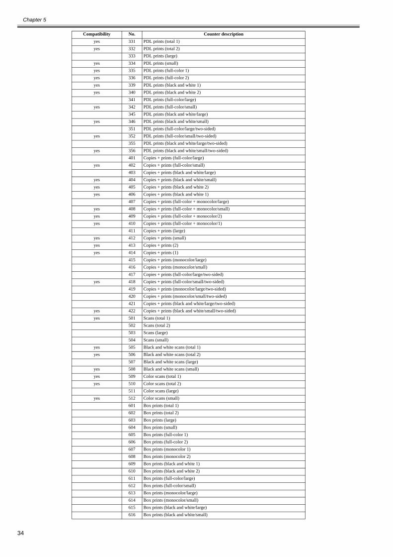
Chapter 5
34
yes 331 PDL prints (total 1)yes 332 PDL prints (total 2)
333 PDL prints (large)yes 334 PDL prints (small)yes 335 PDL prints (full-color 1)yes 336 PDL prints (full-color 2)yes 339 PDL prints (black and white 1)yes 340 PDL prints (black and white 2)
341 PDL prints (full-color/large)yes 342 PDL prints (full-color/small)
345 PDL prints (black and white/large)yes 346 PDL prints (black and white/small)
351 PDL prints (full-color/large/two-sided)yes 352 PDL prints (full-color/small/two-sided)
355 PDL prints (black and white/large/two-sided)yes 356 PDL prints (black and white/small/two-sided)
401 Copies + prints (full-color/large)yes 402 Copies + prints (full-color/small)
403 Copies + prints (black and white/large)yes 404 Copies + prints (black and white/small)yes 405 Copies + prints (black and white 2)yes 406 Copies + prints (black and white 1)
407 Copies + prints (full-color + monocolor/large)yes 408 Copies + prints (full-color + monocolor/small)yes 409 Copies + prints (full-color + monocolor/2)yes 410 Copies + prints (full-color + monocolor/1)
411 Copies + prints (large)yes 412 Copies + prints (small)yes 413 Copies + prints (2)yes 414 Copies + prints (1)
415 Copies + prints (monocolor/large)416 Copies + prints (monocolor/small)417 Copies + prints (full-color/large/two-sided)
yes 418 Copies + prints (full-color/small/two-sided)419 Copies + prints (monocolor/large/two-sided)420 Copies + prints (monocolor/small/two-sided)421 Copies + prints (black and white/large/two-sided)
yes 422 Copies + prints (black and white/small/two-sided)yes 501 Scans (total 1)
502 Scans (total 2)503 Scans (large)504 Scans (small)
yes 505 Black and white scans (total 1)yes 506 Black and white scans (total 2)
507 Black and white scans (large)yes 508 Black and white scans (small)yes 509 Color scans (total 1)yes 510 Color scans (total 2)
511 Color scans (large)yes 512 Color scans (small)
601 Box prints (total 1)602 Box prints (total 2)603 Box prints (large)604 Box prints (small)605 Box prints (full-color 1)606 Box prints (full-color 2)607 Box prints (monocolor 1)608 Box prints (monocolor 2)609 Box prints (black and white 1)610 Box prints (black and white 2)611 Box prints (full-color/large)612 Box prints (full-color/small)613 Box prints (monocolor/large)614 Box prints (monocolor/small)615 Box prints (black and white/large)616 Box prints (black and white/small)
Compatibility No. Counter description
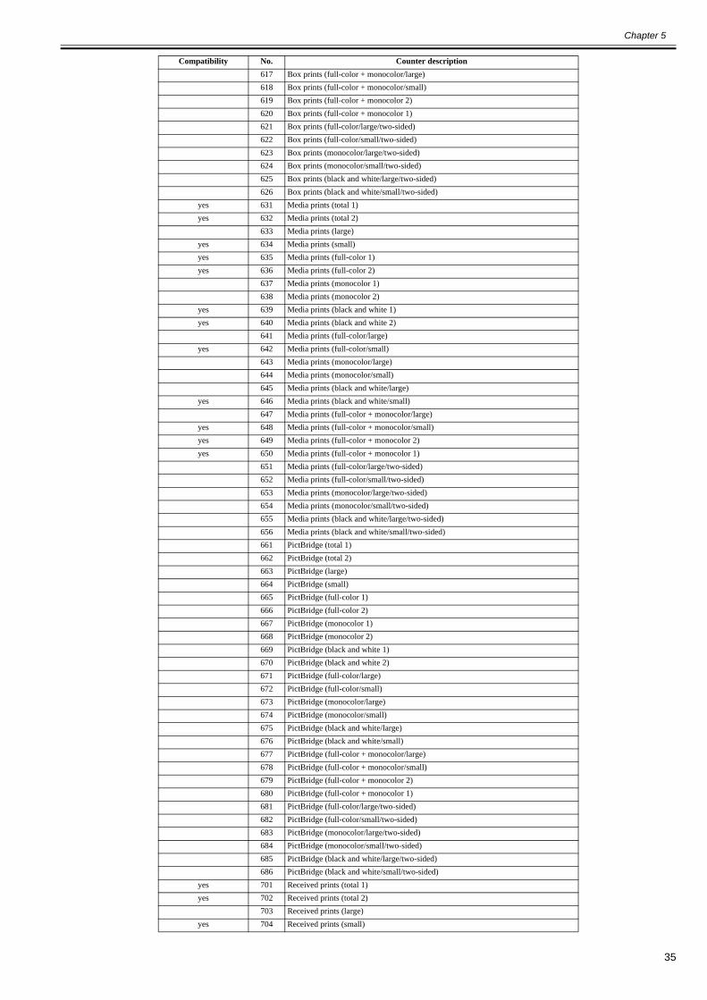
Chapter 5
35
617 Box prints (full-color + monocolor/large)618 Box prints (full-color + monocolor/small)619 Box prints (full-color + monocolor 2)620 Box prints (full-color + monocolor 1)621 Box prints (full-color/large/two-sided)622 Box prints (full-color/small/two-sided)623 Box prints (monocolor/large/two-sided)624 Box prints (monocolor/small/two-sided)625 Box prints (black and white/large/two-sided)626 Box prints (black and white/small/two-sided)
yes 631 Media prints (total 1)yes 632 Media prints (total 2)
633 Media prints (large)yes 634 Media prints (small)yes 635 Media prints (full-color 1)yes 636 Media prints (full-color 2)
637 Media prints (monocolor 1)638 Media prints (monocolor 2)
yes 639 Media prints (black and white 1)yes 640 Media prints (black and white 2)
641 Media prints (full-color/large)yes 642 Media prints (full-color/small)
643 Media prints (monocolor/large)644 Media prints (monocolor/small)645 Media prints (black and white/large)
yes 646 Media prints (black and white/small)647 Media prints (full-color + monocolor/large)
yes 648 Media prints (full-color + monocolor/small)yes 649 Media prints (full-color + monocolor 2)yes 650 Media prints (full-color + monocolor 1)
651 Media prints (full-color/large/two-sided)652 Media prints (full-color/small/two-sided)653 Media prints (monocolor/large/two-sided)654 Media prints (monocolor/small/two-sided)655 Media prints (black and white/large/two-sided)656 Media prints (black and white/small/two-sided)661 PictBridge (total 1)662 PictBridge (total 2)663 PictBridge (large)664 PictBridge (small)665 PictBridge (full-color 1)666 PictBridge (full-color 2)667 PictBridge (monocolor 1)668 PictBridge (monocolor 2)669 PictBridge (black and white 1)670 PictBridge (black and white 2)671 PictBridge (full-color/large)672 PictBridge (full-color/small)673 PictBridge (monocolor/large)674 PictBridge (monocolor/small)675 PictBridge (black and white/large)676 PictBridge (black and white/small)677 PictBridge (full-color + monocolor/large)678 PictBridge (full-color + monocolor/small)679 PictBridge (full-color + monocolor 2)680 PictBridge (full-color + monocolor 1)681 PictBridge (full-color/large/two-sided)682 PictBridge (full-color/small/two-sided)683 PictBridge (monocolor/large/two-sided)684 PictBridge (monocolor/small/two-sided)685 PictBridge (black and white/large/two-sided)686 PictBridge (black and white/small/two-sided)
yes 701 Received prints (total 1)yes 702 Received prints (total 2)
703 Received prints (large)yes 704 Received prints (small)
Compatibility No. Counter description
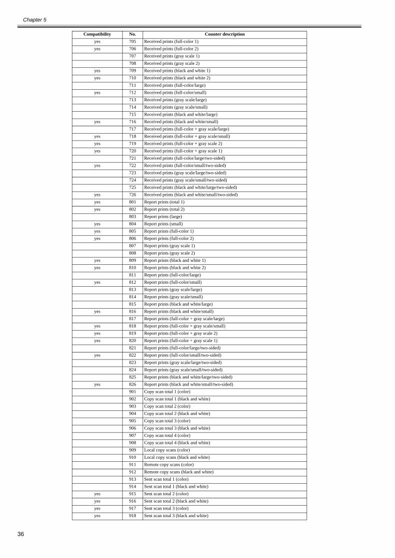
Chapter 5
36
yes 705 Received prints (full-color 1)yes 706 Received prints (full-color 2)
707 Received prints (gray scale 1)708 Received prints (gray scale 2)
yes 709 Received prints (black and white 1) yes 710 Received prints (black and white 2)
711 Received prints (full-color/large)yes 712 Received prints (full-color/small)
713 Received prints (gray scale/large)714 Received prints (gray scale/small)715 Received prints (black and white/large)
yes 716 Received prints (black and white/small)717 Received prints (full-color + gray scale/large)
yes 718 Received prints (full-color + gray scale/small)yes 719 Received prints (full-color + gray scale 2)yes 720 Received prints (full-color + gray scale 1)
721 Received prints (full-color/large/two-sided)yes 722 Received prints (full-color/small/two-sided)
723 Received prints (gray scale/large/two-sided)724 Received prints (gray scale/small/two-sided)725 Received prints (black and white/large/two-sided)
yes 726 Received prints (black and white/small/two-sided)yes 801 Report prints (total 1)yes 802 Report prints (total 2)
803 Report prints (large)yes 804 Report prints (small)yes 805 Report prints (full-color 1)yes 806 Report prints (full-color 2)
807 Report prints (gray scale 1)808 Report prints (gray scale 2)
yes 809 Report prints (black and white 1)yes 810 Report prints (black and white 2)
811 Report prints (full-color/large)yes 812 Report prints (full-color/small)
813 Report prints (gray scale/large)814 Report prints (gray scale/small)815 Report prints (black and white/large)
yes 816 Report prints (black and white/small)817 Report prints (full-color + gray scale/large)
yes 818 Report prints (full-color + gray scale/small)yes 819 Report prints (full-color + gray scale 2) yes 820 Report prints (full-color + gray scale 1)
821 Report prints (full-color/large/two-sided)yes 822 Report prints (full-color/small/two-sided)
823 Report prints (gray scale/large/two-sided)824 Report prints (gray scale/small/two-sided)825 Report prints (black and white/large/two-sided)
yes 826 Report prints (black and white/small/two-sided)901 Copy scan total 1 (color)902 Copy scan total 1 (black and white)903 Copy scan total 2 (color)904 Copy scan total 2 (black and white)905 Copy scan total 3 (color)906 Copy scan total 3 (black and white)907 Copy scan total 4 (color)908 Copy scan total 4 (black and white)909 Local copy scans (color)910 Local copy scans (black and white)911 Remote copy scans (color)912 Remote copy scans (black and white)913 Sent scan total 1 (color)914 Sent scan total 1 (black and white)
yes 915 Sent scan total 2 (color)yes 916 Sent scan total 2 (black and white)yes 917 Sent scan total 3 (color)yes 918 Sent scan total 3 (black and white)
Compatibility No. Counter description
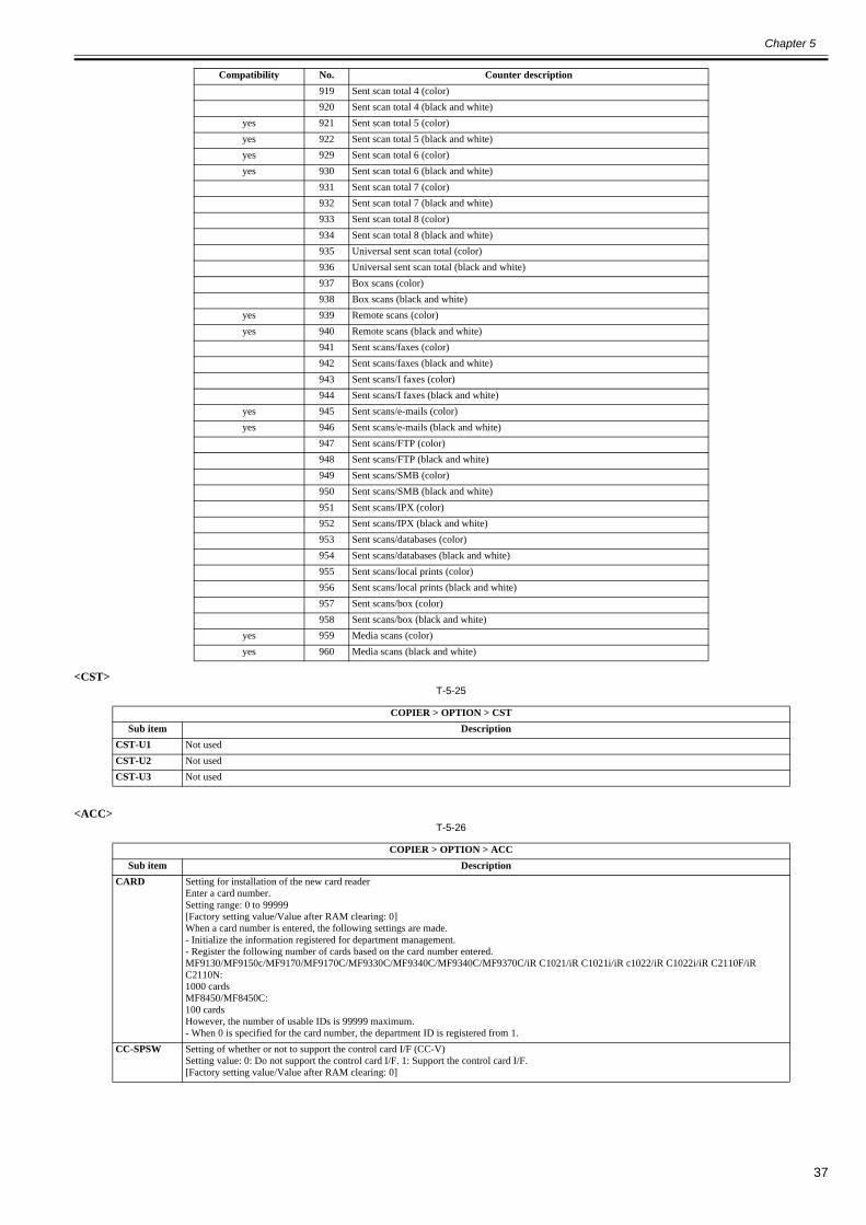
Chapter 5
37
<CST>T-5-25
<ACC>T-5-26
919 Sent scan total 4 (color)920 Sent scan total 4 (black and white)
yes 921 Sent scan total 5 (color)yes 922 Sent scan total 5 (black and white)yes 929 Sent scan total 6 (color)yes 930 Sent scan total 6 (black and white)
931 Sent scan total 7 (color)932 Sent scan total 7 (black and white)933 Sent scan total 8 (color)934 Sent scan total 8 (black and white)935 Universal sent scan total (color)936 Universal sent scan total (black and white)937 Box scans (color)938 Box scans (black and white)
yes 939 Remote scans (color)yes 940 Remote scans (black and white)
941 Sent scans/faxes (color)942 Sent scans/faxes (black and white)943 Sent scans/I faxes (color)944 Sent scans/I faxes (black and white)
yes 945 Sent scans/e-mails (color)yes 946 Sent scans/e-mails (black and white)
947 Sent scans/FTP (color)948 Sent scans/FTP (black and white)949 Sent scans/SMB (color)950 Sent scans/SMB (black and white)951 Sent scans/IPX (color)952 Sent scans/IPX (black and white)953 Sent scans/databases (color)954 Sent scans/databases (black and white)955 Sent scans/local prints (color)956 Sent scans/local prints (black and white)957 Sent scans/box (color)958 Sent scans/box (black and white)
yes 959 Media scans (color)yes 960 Media scans (black and white)
COPIER > OPTION > CSTSub item Description
CST-U1 Not usedCST-U2 Not usedCST-U3 Not used
COPIER > OPTION > ACCSub item Description
CARD Setting for installation of the new card readerEnter a card number.Setting range: 0 to 99999[Factory setting value/Value after RAM clearing: 0]When a card number is entered, the following settings are made.- Initialize the information registered for department management.- Register the following number of cards based on the card number entered.MF9130/MF9150c/MF9170/MF9170C/MF9330C/MF9340C/MF9340C/MF9370C/iR C1021/iR C1021i/iR c1022/iR C1022i/iR C2110F/iR C2110N:1000 cardsMF8450/MF8450C:100 cardsHowever, the number of usable IDs is 99999 maximum.- When 0 is specified for the card number, the department ID is registered from 1.
CC-SPSW Setting of whether or not to support the control card I/F (CC-V)Setting value: 0: Do not support the control card I/F. 1: Support the control card I/F.[Factory setting value/Value after RAM clearing: 0]
Compatibility No. Counter description
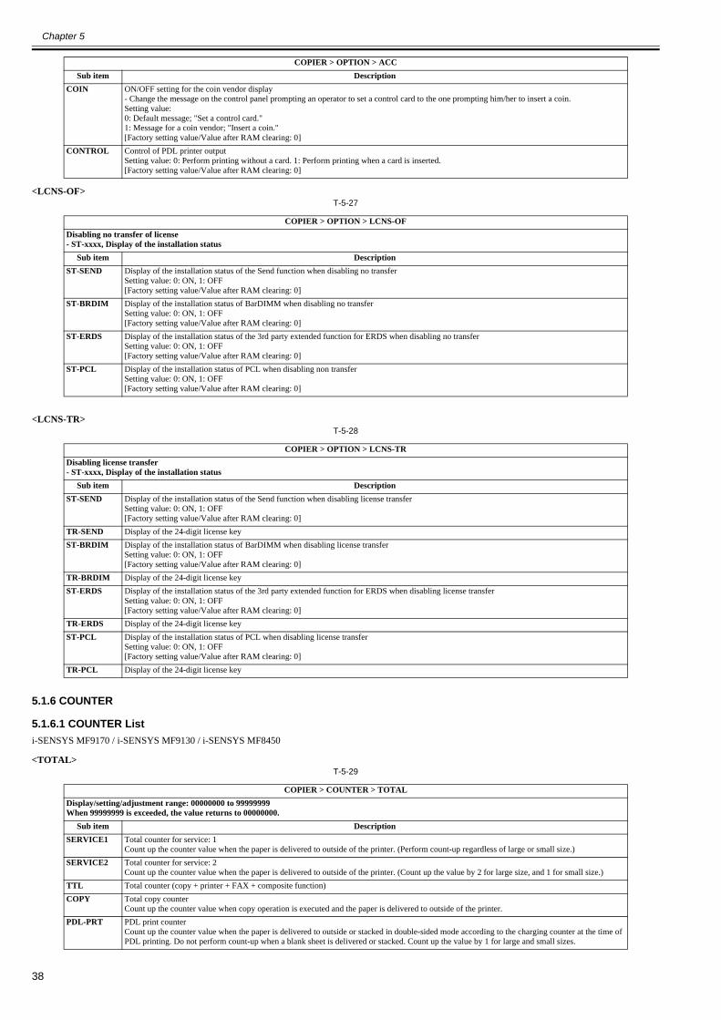
Chapter 5
38
<LCNS-OF>T-5-27
<LCNS-TR>T-5-28
5.1.6 COUNTER
5.1.6.1 COUNTER List0020-2017
i-SENSYS MF9170 / i-SENSYS MF9130 / i-SENSYS MF8450
<TOTAL>T-5-29
COIN ON/OFF setting for the coin vendor display- Change the message on the control panel prompting an operator to set a control card to the one prompting him/her to insert a coin.Setting value:0: Default message; "Set a control card."1: Message for a coin vendor; "Insert a coin."[Factory setting value/Value after RAM clearing: 0]
CONTROL Control of PDL printer outputSetting value: 0: Perform printing without a card. 1: Perform printing when a card is inserted.[Factory setting value/Value after RAM clearing: 0]
COPIER > OPTION > LCNS-OFDisabling no transfer of license- ST-xxxx, Display of the installation status
Sub item DescriptionST-SEND Display of the installation status of the Send function when disabling no transfer
Setting value: 0: ON, 1: OFF[Factory setting value/Value after RAM clearing: 0]
ST-BRDIM Display of the installation status of BarDIMM when disabling no transferSetting value: 0: ON, 1: OFF[Factory setting value/Value after RAM clearing: 0]
ST-ERDS Display of the installation status of the 3rd party extended function for ERDS when disabling no transferSetting value: 0: ON, 1: OFF[Factory setting value/Value after RAM clearing: 0]
ST-PCL Display of the installation status of PCL when disabling non transferSetting value: 0: ON, 1: OFF[Factory setting value/Value after RAM clearing: 0]
COPIER > OPTION > LCNS-TRDisabling license transfer- ST-xxxx, Display of the installation status
Sub item DescriptionST-SEND Display of the installation status of the Send function when disabling license transfer
Setting value: 0: ON, 1: OFF[Factory setting value/Value after RAM clearing: 0]
TR-SEND Display of the 24-digit license keyST-BRDIM Display of the installation status of BarDIMM when disabling license transfer
Setting value: 0: ON, 1: OFF[Factory setting value/Value after RAM clearing: 0]
TR-BRDIM Display of the 24-digit license keyST-ERDS Display of the installation status of the 3rd party extended function for ERDS when disabling license transfer
Setting value: 0: ON, 1: OFF[Factory setting value/Value after RAM clearing: 0]
TR-ERDS Display of the 24-digit license keyST-PCL Display of the installation status of PCL when disabling license transfer
Setting value: 0: ON, 1: OFF[Factory setting value/Value after RAM clearing: 0]
TR-PCL Display of the 24-digit license key
COPIER > COUNTER > TOTALDisplay/setting/adjustment range: 00000000 to 99999999When 99999999 is exceeded, the value returns to 00000000.
Sub item DescriptionSERVICE1 Total counter for service: 1
Count up the counter value when the paper is delivered to outside of the printer. (Perform count-up regardless of large or small size.)SERVICE2 Total counter for service: 2
Count up the counter value when the paper is delivered to outside of the printer. (Count up the value by 2 for large size, and 1 for small size.)TTL Total counter (copy + printer + FAX + composite function)COPY Total copy counter
Count up the counter value when copy operation is executed and the paper is delivered to outside of the printer.PDL-PRT PDL print counter
Count up the counter value when the paper is delivered to outside or stacked in double-sided mode according to the charging counter at the time of PDL printing. Do not perform count-up when a blank sheet is delivered or stacked. Count up the value by 1 for large and small sizes.
COPIER > OPTION > ACCSub item Description
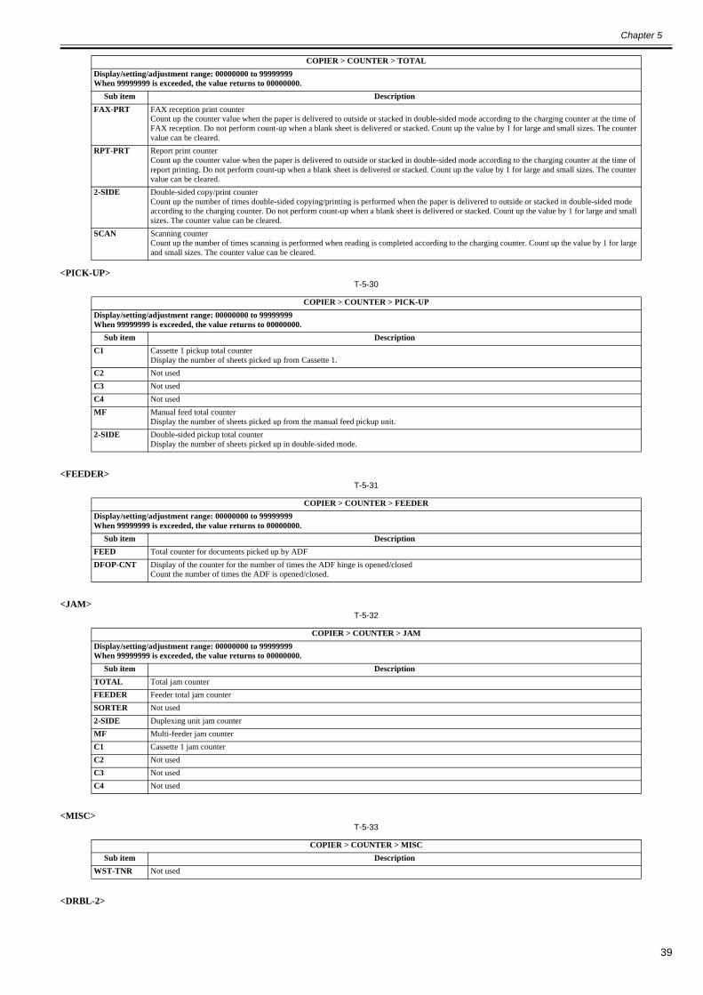
Chapter 5
39
<PICK-UP>T-5-30
<FEEDER>T-5-31
<JAM>T-5-32
<MISC>T-5-33
<DRBL-2>
FAX-PRT FAX reception print counterCount up the counter value when the paper is delivered to outside or stacked in double-sided mode according to the charging counter at the time of FAX reception. Do not perform count-up when a blank sheet is delivered or stacked. Count up the value by 1 for large and small sizes. The counter value can be cleared.
RPT-PRT Report print counterCount up the counter value when the paper is delivered to outside or stacked in double-sided mode according to the charging counter at the time of report printing. Do not perform count-up when a blank sheet is delivered or stacked. Count up the value by 1 for large and small sizes. The counter value can be cleared.
2-SIDE Double-sided copy/print counterCount up the number of times double-sided copying/printing is performed when the paper is delivered to outside or stacked in double-sided mode according to the charging counter. Do not perform count-up when a blank sheet is delivered or stacked. Count up the value by 1 for large and small sizes. The counter value can be cleared.
SCAN Scanning counterCount up the number of times scanning is performed when reading is completed according to the charging counter. Count up the value by 1 for large and small sizes. The counter value can be cleared.
COPIER > COUNTER > PICK-UPDisplay/setting/adjustment range: 00000000 to 99999999When 99999999 is exceeded, the value returns to 00000000.
Sub item DescriptionC1 Cassette 1 pickup total counter
Display the number of sheets picked up from Cassette 1.C2 Not usedC3 Not usedC4 Not usedMF Manual feed total counter
Display the number of sheets picked up from the manual feed pickup unit.2-SIDE Double-sided pickup total counter
Display the number of sheets picked up in double-sided mode.
COPIER > COUNTER > FEEDERDisplay/setting/adjustment range: 00000000 to 99999999When 99999999 is exceeded, the value returns to 00000000.
Sub item DescriptionFEED Total counter for documents picked up by ADFDFOP-CNT Display of the counter for the number of times the ADF hinge is opened/closed
Count the number of times the ADF is opened/closed.
COPIER > COUNTER > JAMDisplay/setting/adjustment range: 00000000 to 99999999When 99999999 is exceeded, the value returns to 00000000.
Sub item DescriptionTOTAL Total jam counterFEEDER Feeder total jam counterSORTER Not used2-SIDE Duplexing unit jam counterMF Multi-feeder jam counterC1 Cassette 1 jam counterC2 Not usedC3 Not usedC4 Not used
COPIER > COUNTER > MISCSub item Description
WST-TNR Not used
COPIER > COUNTER > TOTALDisplay/setting/adjustment range: 00000000 to 99999999When 99999999 is exceeded, the value returns to 00000000.
Sub item Description
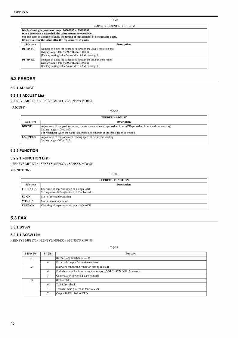
Chapter 5
40
T-5-34
5.2 FEEDER
5.2.1 ADJUST
5.2.1.1 ADJUST List0020-2018
i-SENSYS MF9170 / i-SENSYS MF9130 / i-SENSYS MF8450
<ADJUST>T-5-35
5.2.2 FUNCTION
5.2.2.1 FUNCTION List0020-2019
i-SENSYS MF9170 / i-SENSYS MF9130 / i-SENSYS MF8450
<FUNCTION>T-5-36
5.3 FAX
5.3.1 SSSW
5.3.1.1 SSSW List0020-2020
i-SENSYS MF9170 / i-SENSYS MF9130 / i-SENSYS MF8450
T-5-37
COPIER > COUNTER > DRBL-2Display/setting/adjustment range: 00000000 to 99999999When 99999999 is exceeded, the value returns to 00000000.Use this item as a guide to know the timing of replacement of consumable parts.Be sure to clear the value after the replacement of parts.
Sub item DescriptionDF-SP-PD Number of times the paper goes through the ADF separation pad
Display range: 0 to 999999 (Limit: 50000)[Factory setting value/Value after RAM clearing: 0]
DF-SP-RL Number of times the paper goes through the ADF pickup rollerDisplay range: 0 to 999999 (Limit: 50000)[Factory setting value/Value after RAM clearing: 0]
FEEDER > ADJUSTSub item Description
DOCST Adjustment of the position to stop the document when it is picked up from ADF (picked up from the document tray)Setting range: -100 to 100For reference: When the value is increased, the margin at the lead edge is decreased.
LA-SPEED Adjustment of the document feeding speed at DF stream readingSetting range: -512 to 512
FEEDER > FUNCTIONSub item Description
FEED-CHK Checking of paper transport at a single ADFSetting value: 0: Single-sided, 1: Double-sided
SL-ON Start of solenoid operationMTR-ON Start of motor operationFEED-ON Checking of paper transport at a single ADF
SSSW No. Bit No. Function01 (Error, Copy function-related)
0 Error code output for service engineer02 (Network connecting condition setting-related)
4 Forbid communication control that supports V34 CCRTN OFF IP network7 Connect as F-network 2-type terminal
03 (Echo-related)0 TCF EQM check1 Transmit echo protection tone to V.297 Output 1080Hz before CED

Chapter 5
41
04 (Communication trouble-related)1 Check frequency of CI signal2 V.21 end flag3 Forbid duplex waiting of T.30 node4 T.30 node F echo timer5 Check frequency of CI signal at PBX settings6 Do not deliver CNG at manual transmission7 Do not deliver CED at manual reception
05 (Standard function, DIS signal setting-related)1 mm/inch convert (text mode)2 mm/inch convert (text photo/photo mode)3 Forbid bit delivery after bit 33 of DIS4 Cut paper declaration
06 (Scanning condition settings)4 Scanning width 0: A4, 1: LTR
12 (Page timer settings-related) Time by 2-bit combination(0, 0): 8 min, (0, 1): 16 min, (1, 0): 32 min, (1, 1): 64min
When bit 7 is 0:- 1page timeout time is specified with bit 1 and bit 0 regardless of any mode communication.When bit 7 is 1:- The timeout time for general transmission is specified with bit 1 and bit 0, for HT transmission with bit 3 and bit 2, for reception with bit 5 and bit 4
0 1 page timeout time (transmission)12 1 page timeout time (HT transmission)34 1 page timeout time (reception)57 1 page timeout time
132 Convert mm/inch when sending received image
142 Whether executing inch to mm conversion in both main and sub scanning directions, or in sub scanning direction only4 Perform inch-type resolution declaration
152 Accept receiving ND line: Host machine line6 Detect continuous signal at F/T switching
180 Detect carrier disconnection between DCS and TCF1 Waiting time for carrier disconnection between DCS and TCF2 Forbid communication control for IP network
220 Forbid delivering NSX3 Forbid manual polling operation
25 (Report display function settings-related)0 Prioritize received phone number to dialed number2 When receiving blank CSI, regard the CSI as not-received3 Message language selection user SW
280 Forbid V8 procedure at calling side1 Forbid V8 procedure at receiving side2 Forbid V8 late start at calling side3 Forbid V8 late start at receiving side4 Forbid fallback start from V.34 receiving side5 Forbid fallback start from V.34 sending side
305 New dial tone detection method
325 0: NCU2004, 1: NCU2002
330 (Record) whether to count B4 size as large size or not2 (Scan) whether to count B4 size as large size or not5 Display toner replacement counter
350 e-RDS function (0: OFF/1: ON)
SSSW No. Bit No. Function

Chapter 5
42
5.3.2 MENU
5.3.2.1 MENU List0020-2021
i-SENSYS MF9170 / i-SENSYS MF9130 / i-SENSYS MF8450
T-5-38
5.3.3 NUM
5.3.3.1 NUM List0020-2022
i-SENSYS MF9170 / i-SENSYS MF9130 / i-SENSYS MF8450
T-5-39
5.3.4 NCU
5.3.4.1 NCU List0020-2023
i-SENSYS MF9170 / i-SENSYS MF9130 / i-SENSYS MF8450
<TONE/ PULSE>
Registration mode of menu switchNumber Parameter Description of the selection
05 ON/OFF of NL equalizer 0: OFF, 1: ON06 Telephone line monitor 0: DIAL, 1: SERVICEMAN1, 2: SERVICEMAN2, 3: OFF07 Delivery level (ATT) 0-1508 Upper limit of V.34 modulating speed 0: 3429BAUD, 1: 3200BAUD, 2: 3000BAUD,
3: 2800BAUD, 4: 2743BAUD, 5: 2400BAUD09 Upper limit of V. 34 data speed (Unit: kbps)
0: 33.6, 1: 31.2, 2: 28.8, 3: 26.4, 4: 24.0, 5: 21.6, 6: 19.2, 7: 16.8, 8: 14.4, 9: 12.0, 10: 9.6, 11: 7.2, 12: 4.8, 13: 2.4
10 Frequency of pseudo CI signal 0: 50 Hz, 1: 25 Hz, 2: 17 Hz
Numeric parameter setting modeNumber Parameter Available setting range
02 RTN delivery condition X 1 to 99%03 RTN delivery condition n 2 to 99 times04 RTN delivery condition m 1 to 99 lines05 NCC pause time (before ID code) 1 to 60 s06 NCC pause time (after ID code) 1 to 60 s10 T.30 T0 timer Generally 55s Åi75âÒíþï°å§åàíËÅj11 T.30 T1 timer (for receiving) 0 to 9999 (France = 3500, Others = 3000)12 Maximum number of receiving lines 0 to 65535 (lines) Unlimited for 013 T.30 EOL timer 500 to 3000 (Default: 55s) 75âÒíþï°å§åàíËÅj15 Threshold for hooking and on-hook 0 to 99916 Time to temporarily response at FAX/TEL switching 0 to 917 Pseudo RBT cadence ON time 0 to 99918 Pseudo RBT cadence OFF time (short) 0 to 99919 Pseudo RBT cadence OFF time (long) 0 to 99920 Pseudo ring tone cadence ON time 0 to 99921 Pseudo CI cadence OFF time (short) 0 to 99922 Pseudo CI cadence OFF time (long) 0 to 99923 CNG detection level at FAX/TEL switching 0 to 724 Pseudo RBT delivery level at FAX/TEL switching 10 to 20 (100V),
0 to 20 (120/ 230V)25 CNG monitoring time when answer phone is used 0 to 99926 Level to detect no-sound when answer phone is used 0 to 727 Preamble detection time of V21 low-speed flag 20 (* 10ms)51 Threshold value of hook detection 10 to 53 Set the number of DTMF ringing times at FAX remote reception 10 to (Default: 25)54 Set the transmission time of BusyTone when the handset is used55 Cycle to obtain data of environment log 0 to 480 min (Default: 60min) (No data is obtained with 0)56 Select counter type to be displayed at counter 1 10157 Select counter type to be displayed at counter 2 0 to 99958 Select counter type to be displayed at counter 3 0 to 99959 Select counter type to be displayed at counter 4 0 to 99960 Select counter type to be displayed at counter 5 0 to 99961 Select counter type to be displayed at counter 6 0 to 99974 Port number of e-RDS RGW75 Transmission interval of e-RDS for 3rd party
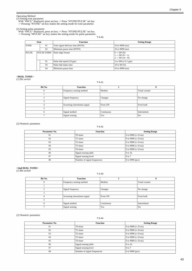
Chapter 5
43
Operating Method(1) Setting tone parameter With "#NCU" displayed, press set key -> Press "#TONE/PULSE" set key -> Pressing "#TONE" set key makes the setting mode for tone parameter.
(2) Setting pulse parameter With "#NCU" displayed, press set key -> Press "#TONE/PULSE" set key. -> Pressing "#PULSE" set key makes the setting mode for pulse parameter.
T-5-40
<DIAL TONE>(1) Bit switch
T-5-41
(2) Numeric parameterT-5-42
<2nd DIAL TONE>(1) Bit switch
T-5-43
(2) Numeric parameterT-5-44
Item Function Setting RangeTONE 01 Tone signal delivery time (PSTN) 10 to 9999 (ms)
02 Minimum pause time (PSTN) 10 to 9999 (ms)PULSE PULSE FORM Pulse digit format 0 -> DP (N)
1 -> DP (N + 1)2 -> DP (10 - N)
01 Pulse dial speed (10 pps) 5 to 300 (x 0.1 pps)03 Pulse dial make ratio 10 to 90 (%)04 Minimum pause time 10 to 9999 (ms)
Bit No. Function 1 00 Frequency sensing method Modem Tonal counter12 Signal frequency Changes No change34 Screening intermittent signal From ON From both56 Signal method Continuous Intermittent7 Signal sensing Yes No
Parameter No. Function Setting Range01 T0 timer 0 to 9999 (x 10 ms)02 T1 timer 0 to 9999 (x 10 ms)03 T2 timer 0 to 9999 (x 10 ms)04 T3 timer 0 to 9999 (x 10 ms)05 T4 timer 0 to 9999 (x 10 ms)06 Signal sensing table 0 to 1607 Signal sensing level 0 to 708 Number of signal frequencies 0 to 9999 (pce)

Chapter 5
44
<BUSY TONE 0>(1) Bit switch
T-5-45
(2) Numeric parameterT-5-46
<BUSY TONE 1>(1) Bit switch
T-5-47
(2) Numeric parameterT-5-48
<REORDER TONE>(1) Bit switch
T-5-49
(2) Numeric parameter
Bit No. Function 1 0012 Signal frequency Changes No change34 Screening intermittent signal From ON From both56 Signal method Continuous Intermittent7 Signal sensing Yes No
Parameter No. Function Setting Range0102 T1 timer 0 to 9999 (x 10 ms)03 T2 timer 0 to 9999 (x 10 ms)04 T3 timer 0 to 9999 (x 10 ms)05 T4 timer 0 to 9999 (x 10 ms)06 Signal sensing table 0 to 1607 Signal sensing level 0 to 708 Number of signal frequencies 0 to 9999 (pce)
Bit No. Function 1 0012 Signal frequency Changes No change3 RBT signal detection Yes No4 Screening intermittent signal From On From Both5 RBT signal checking cycle 1 cycle 1/2 cycle6 Signal format Continuous Intermittent7 Signal sensing Yes No
Parameter No. Function Setting Range0102 T1 timer 0 to 9999 (x 10 ms)03 T2 timer 0 to 9999 (x 10 ms)04 T3 timer 0 to 9999 (x 10 ms)05 T4 timer 0 to 9999 (x 10 ms)06 Signal sensing table 0 to 1607 Signal sensing level 0 to 708 Number of signal frequencies 0 to 9999 (pce)
Bit No. Function 1 001 Signal sensing method FED FR32 Signal frequency Changes No change34 Screening intermittent signal From ON From both56 Signal format Continuous Intermittent7 Signal sensing Yes No

Chapter 5
45
T-5-50
<AUTO RX>(1) Numeric parameter
T-5-51
<CNG DETECT>(1) Numeric parameter
T-5-52
<SPECIAL N>T-5-53
Parameter No. Function Setting Range0102 T1 timer 0 to 9999 (x 10 ms)03 T2 timer 0 to 9999 (x 10 ms)04 T3 timer 0 to 9999 (x 10 ms)05 T4 timer 0 to 9999 (x 10 ms)06 Signal sensing table 0 to 1607 Signal sensing level 0 to 708 Number of signal frequencies 0 to 9999 (pce)
Parameter No. Function Setting Range01 CI ON time 0 to 9999 (x 10 ms)02 CI LONG ON time 0 to 9999 (x 10 ms)03 CI OFF time 0 to 9999 (x 10 ms)04 CI LONG OFF time 0 to 9999 (x 10 ms)05 CI MAX OFF time 0 to 9999 (x 10 ms)06 CI WAIT time 0 to 9999 (x 10 ms)07 CI frequency 0 to 9999 (cycle)08 Lower limit of CI frequency 0 to 9999 (Hz)09 Upper limit of CI frequency 0 to 9999 (Hz)
Parameter No. Setting description Setting range01 At F/T switching CNG MIN ON time 0 to 9999 (x 10 ms)02 CNG MAX ON time 0 to 9999 (x 10 ms)06 Hit ratio 0 to 9999 (%)07 When answer phone is directly
connectedCNG MIN ON time 0 to 9999 (x 10 ms)
08 CNG MAX ON time 0 to 9999 (x 10 ms)09 instantaneous interruption tolerable
time0 to 9999 (x 10 ms)
11 Number of detection 0 to 9999 (times)12 Hit ratio 0 to 9999 (%)
Number
Setting Description Setting Range
04 CTC/EOR delivery timing 1 to 9 (times)05 High speed flag delivery time in ECM mode 20 to 500 (x 10 ms)06 Continuous delivery of 1 before image signal delivery 20 to 200 (x 10 ms)07 Time from S relay ON to P relay OFF 0 to 9999 (x 10 ms)08 Time that ring back tone parameter is ON 0 to 9999 (x 10 ms)09 Time that ring back tone parameter is OFF 0 to 9999 (x 10 ms)11 Lower limit in setting range for redial interval 2 to 99 (min)12 DTMF delivery level (H1-3, PSTN) 0 to -16 (dBm)13 DTMF delivery level (L1-4, PSTN) 0 to -16 (dBm)14 ECM T5 timer 60 to 480 (sec)15 ECM CD timer 0 to 9999 (ms)16 CED detection level 0 to 917 Upper limit for F/T calling time 0 to 9999 (sec)19 Number of trail edge margin (lines) at image's trail edge 0 to 9999 (lines)20 Time to capture F/T line 0 to 9999 (sec) Special SW17 bit 424 Delivery time for V34 control cannel flag 0 to 100 (x 10 ms)25 Delivery time for V34 primary channel flag 20 to 500 (x 10 ms)26 V34 fallback speed 1 to 4 (x 2.4 kbps)27 Number of PPR to start V34 fallback 1 to 9 (times)30 T2 timer 6 to 30 (sec)40 Setting T2 timer value for V34 communication41 Synchronization interval for RETRY to use for synchronization of V8 procedure signal ‘PC -> CC’ at
the time of receiving FAX

Chapter 5
46
<RKEY>(1) Numeric parameter
T-5-54
<PBX DIAL TONE>(1) Bit switch
T-5-55
(2) Numeric parameterT-5-56
<PBX BUSY TONE>(1) Bit switch
T-5-57
(2) Numeric parameterT-5-58
44 Number of times of RETRY to use for synchronization of V8 procedure signal ‘PC -> CC’ at the time of receiving FAX
45 Waiting time with î¦åƒëODTåüímã@î\ OFF46 Time to identify DialTone signal47 Time of not being disconnected in the case that DialTone signal is disconnected65 Number of maximum lines of A4 paper at the time of sending ÉJÉbÉgéÜ66 Number of maximum lines of B4 paper at the time of sending ÉJÉbÉgéÜ
Parameter No. Function Setting Range01 Flash connection time 0 to 9999 (x 10 ms)02 Grounding time 0 to 9999 (x 10 ms)
Bit No. Function 1 00 Frequency sensing method Modem Tonal counter12 Signal frequency Changes No change34 Screening intermittent signal From ON From both56 Signal format Continuous Intermittent7 Signal sensing Yes No
Parameter No. Function Setting Range01 T0 timer 0 to 9999 (x 10 ms)02 T1 timer 0 to 9999 (x 10 ms)03 T2 timer 0 to 9999 (x 10 ms)04 T3 timer 0 to 9999 (x 10 ms)05 T4 timer 0 to 9999 (x 10 ms)06 Signal sensing table 0 to 1607 Signal sensing level 0 to 908 Number of signal frequencies 0 to 9999 (pce)
Bit No. Function 1 0012 Signal frequency Changes No change34 Screening intermittent signal From ON From both56 Signal format Continuous Intermittent7 Signal sensing Yes No
Parameter No. Function Setting Range0102 T1 timer 0 to 9999 (x 10 ms)03 T2 timer 0 to 9999 (x 10 ms)04 T3 timer 0 to 9999 (x 10 ms)05 T4 timer 0 to 9999 (x 10 ms)06 Signal sensing table 0 to 1607 Signal sensing level 0 to 908 Number of signal frequencies 0 to 9999 (pce)
Number
Setting Description Setting Range
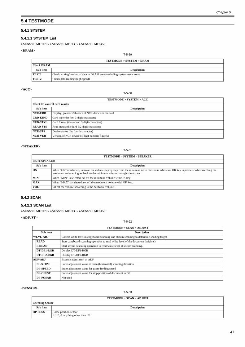
Chapter 5
47
5.4 TESTMODE
5.4.1 SYSTEM
5.4.1.1 SYSTEM List0020-2024
i-SENSYS MF9170 / i-SENSYS MF9130 / i-SENSYS MF8450
<DRAM>T-5-59
<ACC>T-5-60
<SPEAKER>T-5-61
5.4.2 SCAN
5.4.2.1 SCAN List0020-2025
i-SENSYS MF9170 / i-SENSYS MF9130 / i-SENSYS MF8450
<ADJUST>T-5-62
<SENSOR>T-5-63
TESTMODE > SYSTEM > DRAMCheck DRAM
Sub item DescriptionTEST1 Check writing/reading of data in DRAM area (excluding system work area)TEST2 Check data reading (high speed)
TESTMODE > SYSTEM > ACCCheck ID control card reader
Sub item DescriptionNCR-CRD Display: presence/absence of NCR device or the cardCRD-KIND Card type (the first 3-digit characters)CRD-STYL Card format (the second 3-digit characters)READ-STS Read status (the third 3/2-digit characters)NCR-STS Device status (the fourth character)NCR-VER Version of NCR device (4-digit numeric figures)
TESTMODE > SYSTEM > SPEAKERCheck SPEAKER
Sub item DescriptionON When "ON" is selected, increase the volume step by step from the minimum up to maximum whenever OK key is pressed. When reaching the
maximum volume, it goes back to the minimum volume through silent state.MIN When "MIN" is selected, set off the minimum volume with OK key.MAX When "MAX" is selected, set off the maximum volume with OK key.VOL Set off the volume according to the hardware volume.
TESTMODE > SCAN > ADJUSTSub item Description
WLVL-ADJ Correct white level in copyboard scanning and stream scanning to determine shading target.READ Start copyboard scanning operation to read white level of the document (original).F-READ Start stream scanning operation to read white level at stream scanning.DT-DF1-RGB Display DT-DF1-RGBDT-DF2-RGB Display DT-DF2-RGB
ADF-ADJ Execute adjustment of ADFDF-STRM Enter adjustment value in main (horizontal) scanning directionDF-SPEED Enter adjustment value for paper feeding speedDF-OFFST Enter adjustment value for stop position of document in DFDF-POSAD Not used
TESTMODE > SCAN > ADJUSTChecking Sensor
Sub item DescriptionHP-SENS Home position sensor
1: HP, 0: anything other than HP

Chapter 5
48
<ADFTEST>T-5-64
<BOOKFEED>T-5-65
5.4.3 PRINT
5.4.3.1 PRINT List0020-2026
i-SENSYS MF9170 / i-SENSYS MF9130 / i-SENSYS MF8450
<PRINT>T-5-66
TP-SENS Sensor for paper in tray1: presence of paper, 0: no paper
REG-SENS Pre-registration sensor1: presence of paper, 0: no paper
ESS-SENS Front door sensor1: ON, 0: OFF
TESTMODE > SCAN > ADFTESTADF Feeding TestExecute feeding operation according to the scanning feeding speed (specified in SPEED, 2-SIDE, COUNT)
Sub item DescriptionSPEED Specify ADF feeding speed2-SIDE Select ON/OFF for duplex modeCOUNT Counter for the number of document (originals): YesSTART Start feeding
TESTMODE > SCAN > BOOKFEEDTesting Book Feed Operation
Sub item DescriptionPAGE Display the number of pages that had been book-fedSTART Start book feeding
TESTMODE > PRINTPrinting PG pattern
Sub item DescriptionPG-TYPE Enter PG numberCOUNT Enter the number to be outputPHASE Select 1-sided/2-sidedMODE Not usedTHRU Selection is available for gamma correction (ON/OFF)DENS-M Not usedDENS-C Not usedDENS-Y Not usedDENS-K Not usedCOLOR-M Selection for each color is available
The selected color (ON) is to be output.Setting value: 1: ON, 0: OFF
COLOR-C Selection for each color is availableThe selected color (ON) is to be output.Setting value: 1: ON, 0: OFF
COLOR-Y Selection for each color is availableThe selected color (ON) is to be output.Setting value: 1: ON, 0: OFF
COLOR-K Selection for each color is availableThe selected color (ON) is to be output.Setting value: 1: ON, 0: OFF
SIZE Display paper sizePAPER Display presence/absence of paperMATERIAL Display paper typeF-UP-DWN Not usedFEED Selection for the pickup positionSTART Start PG pattern print
Execute output that has been selected above by pressing it.
TESTMODE > SCAN > ADJUSTChecking Sensor
Sub item Description

Chapter 5
49
5.4.4 FAX
5.4.4.1 FAX List0020-2027
i-SENSYS MF9170 / i-SENSYS MF9130 / i-SENSYS MF8450
<MODEM>T-5-67
<FACULTY>T-5-68
5.4.5 PANEL
5.4.5.1 PANEL List0020-2028
i-SENSYS MF9170 / i-SENSYS MF9130 / i-SENSYS MF8450
<PANEL>T-5-69
TESTMODE > FAX > MODEMSub item Description
RELAY-1 Test ON/OFF state of NCU's each relay and port SWRELAY-2 Test ON/OFF state of NCU's each relay and port SWFREQ Close DC circuit to deliver the selected frequency using the modem's tone delivery function.G3TX Close DC circuit to deliver the selected signal pattern with the selected frequency using the modem's G3 signal delivery function.DTMFTX Close DC circuit to deliver DTMF signal using the modem's DTMF delivery function.V34G3TX Close DC circuit to deliver the selected frequency using the modem's G3 signal delivery function (V. 34)
TESTMODE > FAX > FACULTYSub item Description
G34800TX Close DC circuit to deliver the frequency of 4800bps using the modem's G3 signal delivery function.DETECT1 Ring detection
Check Ci, Fc and hook state (ON, OFF) from l-line.DETECT2 CNG detection test 1
Check CNG signal and FEDMake CML relay at ON state to detect CNG
DETECT3 CNG detection test 2Check CNG signal and FEDMake CML relay at OFF state to detect CNG
TESTMODE > PANELChecking LCD, LED, Key
Sub item DescriptionKEY-CHK Check KeyLED-CHK Check LEDLCD-CHK Check LCDFLCK-CHK Check flicker

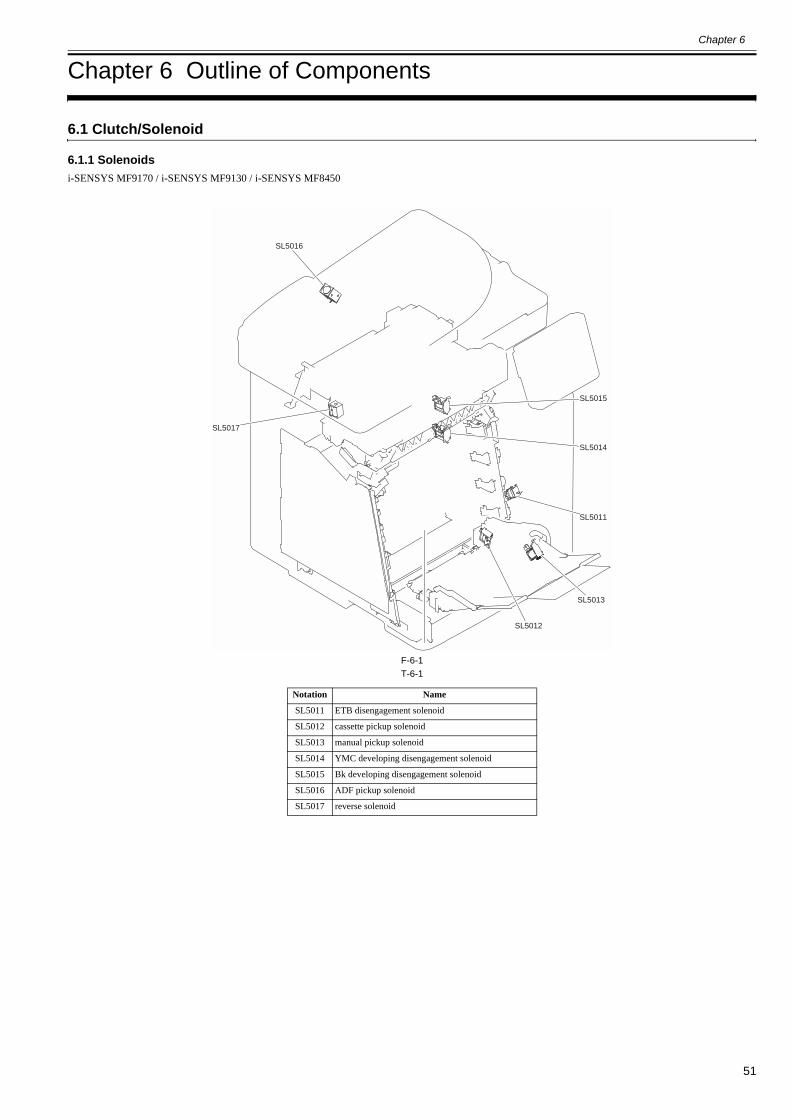
Chapter 6
51
Chapter 6 Outline of Components
6.1 Clutch/Solenoid
6.1.1 Solenoids0019-5061
i-SENSYS MF9170 / i-SENSYS MF9130 / i-SENSYS MF8450
F-6-1T-6-1
Notation Name
SL5011 ETB disengagement solenoid
SL5012 cassette pickup solenoid
SL5013 manual pickup solenoid
SL5014 YMC developing disengagement solenoid
SL5015 Bk developing disengagement solenoid
SL5016 ADF pickup solenoid
SL5017 reverse solenoid
SL5016
SL5017
SL5011
SL5015
SL5014
SL5012
SL5013

Chapter 6
52
6.2 Sensor
6.2.1 Sensors0019-9003
i-SENSYS MF9170 / i-SENSYS MF9130 / i-SENSYS MF8450
F-6-2T-6-2
Notation Name
PS301 YMC developing disengagement sensor
PS302 Bk developing disengagement sensor
PS303 new cartridge sensor
SR701 M drum HP sensor
SR702 C drum HP sensor
SR703 Y drum HP sensor
SR704 Bk drum HP sensor
SR717 reader HP sensor
SR718 ADF paper sensor
SR719 ADF paper trailing edge sensor
SR718
SR719
SR717
PS303
PS302
PS301
SR704
SR703
SR702
SR701
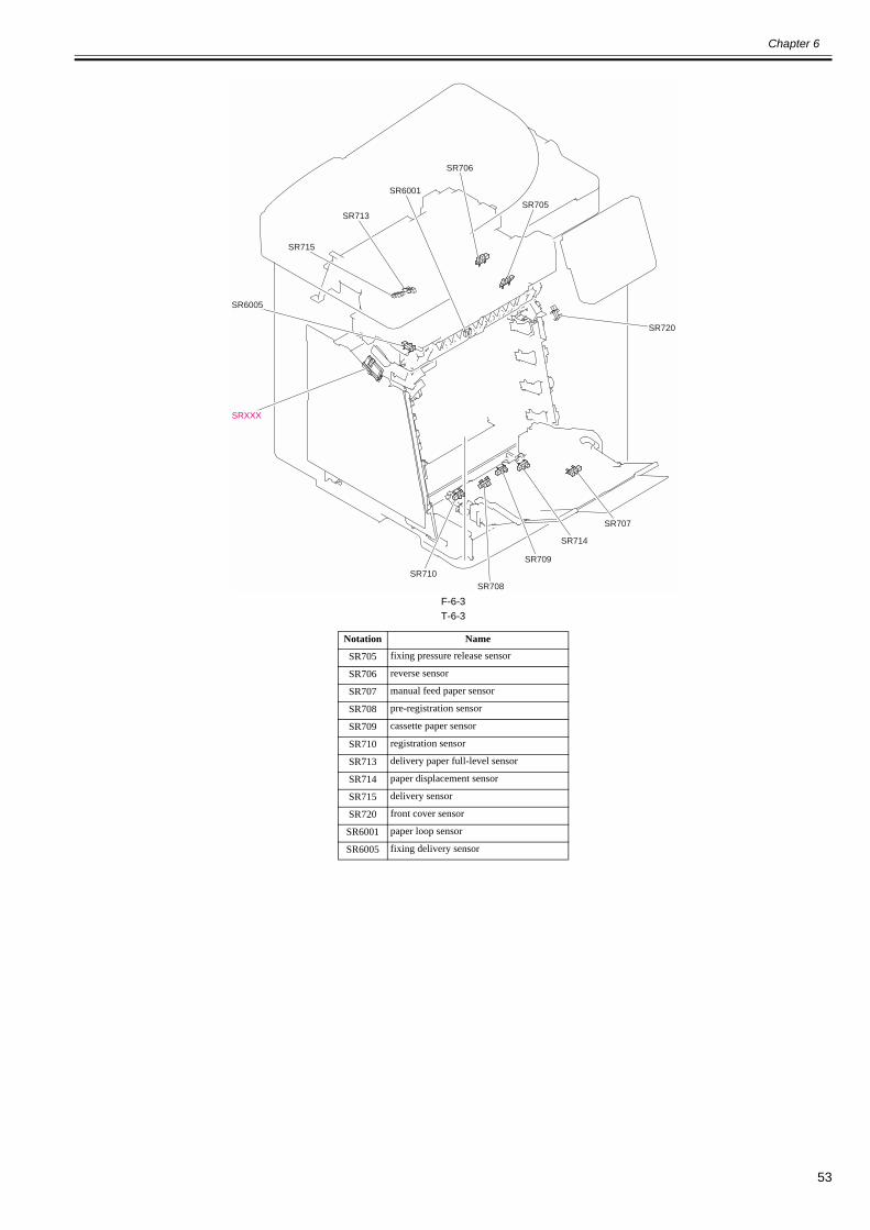
Chapter 6
53
F-6-3T-6-3
Notation Name
SR705 fixing pressure release sensor
SR706 reverse sensor
SR707 manual feed paper sensor
SR708 pre-registration sensor
SR709 cassette paper sensor
SR710 registration sensor
SR713 delivery paper full-level sensor
SR714 paper displacement sensor
SR715 delivery sensor
SR720 front cover sensor
SR6001 paper loop sensor
SR6005 fixing delivery sensor
SR720
SRXXX
SR707
SR708SR710
SR709
SR714
SR713
SR715
SR706
SR705
SR6001
SR6005
Chapter 6
54
6.3 Switch
6.3.1 Switches, Speaker, and Thermistors0019-9004
i-SENSYS MF9170 / i-SENSYS MF9130 / i-SENSYS MF8450
F-6-4T-6-4
Notation Name
SW1 front cover detection switch
SW2 cassette detection switch
SW3 delivery cover detection switch
SW4 power switch
SW1
SW3
SW4
SW2
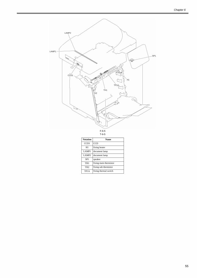
Chapter 6
55
F-6-5T-6-5
Notation Name
CCD1 CCD
H1 fixing heater
LAMP1 document lamp
LAMP2 document lamp
SP1 speaker
TH1 fixing main thermistor
TH2 fixing sub thermistor
TP1A fixing thermal switch
TP1A
H1
SP1
TH1
TH2
LAMP2
LAMP1
CCD1

Chapter 6
56
6.4 PCBs
6.4.1 PCBs0019-5065
i-SENSYS MF9170 / i-SENSYS MF9130 / i-SENSYS MF8450
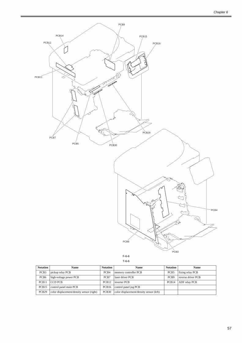
Chapter 6
57
F-6-6
T-6-6
Notation Name Notation Name Notation Name
PCB3 pickup relay PCB PCB4 memory controller PCB PCB5 fixing relay PCB
PCB6 high-voltage power PCB PCB7 laser driver PCB PCB9 reverse driver PCB
PCB11 CCD PCB PCB12 inverter PCB PCB14 ADF relay PCB
PCB15 control panel main PCB PCB16 control panel jog PCB
PCB29 color displacement/density sensor (right) PCB30 color displacement/density sensor (left)
PCB11
PCB7
PCB12
PCB14
PCB30PCB5
PCB9
PCB15
PCB16
PCB29
PCB4
PCB3
PCB6

Chapter 6
58
F-6-7
T-6-7
Notation Name
PCB1 DC controller PCB
PCB2 driver PCB
PCB8 low-voltage power PCB
PCB13 CCD relay PCB
PCB17 control panel relay PCB
PCB18 main controller PCB
PCB19 modular PCB
PCB20 modular PCB
PCB21 modular PCB
PCB24 NCU PCB
PCB25 serial I/F PCB
PCB26 pseudo CI PCB (for Japan)
PCB27 off hook PCB (for outside Japan)
PCB28 environment sensor
PCB8
PCB1
PCB2
PCB18
PCB25PCB19 / 20 / 21 PCB24
PCB28
PCB26 /27
PCB17
PCB13
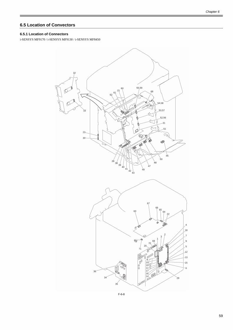
Chapter 6
59
6.5 Location of Convectors
6.5.1 Location of Connectors0020-1529
i-SENSYS MF9170 / i-SENSYS MF9130 / i-SENSYS MF8450
F-6-8
32
23
6261
2160
45
31
51
50
48
47
49
63
71
67
6665
6422
4
18
7
9
5
12
13
15
6
29
169
7020
8101911171614
35
34
36
32
4342
4140
3938
28
68
30
33
55,59
54,58
53,57
52,56

Chapter 6
60
T-6-8
No. Notation J No. Electric parts name Relay connector No. J No. Notation Electric parts name Remarks
1 PCB1 J1001 DC controller PCB 20 J8112 PCB18 main controller PCB2 PCB1 J1002 DC controller PCB J6007 21 J6001 PCB6 fixing relay PCB3 PCB1 J1004 DC controller PCB J5027 22 J3004 PCB8 low-voltage power PCB4 PCB1 J1006 DC controller PCB J5026 4 - PCB8 low-voltage power PCB5 PCB1 J1008 DC controller PCB 5 J1008 FM1 main unit fan6 PCB1 J1009 DC controller PCB 23 J2001 PCB6 high-voltage power PCB7 PCB1 J1010 DC controller PCB 24 J101 PCB7 laser driver PCB8 PCB1 J1011 DC controller PCB J5028 25 - ëäéËêÊïsñæ9 PCB1 J1012 DC controller PCB 26 J102 PCB7 laser driver PCB
10 PCB1 J1013 DC controller PCB J5029 27 - ëäéËêÊïsñæ11 PCB1 J1014 DC controller PCB 28 J7001 PCB3 pickup relay PCB12 PCB1 J1018 DC controller PCB 29 J8002 PCB28 environment sensor13 PCB1 J1019 DC controller PCB 30 J2002 PCB6 high-voltage power PCB14 PCB1 J1020 DC controller PCB 31 J301 PCB4 memory controller PCB15 PCB1 J1021 DC controller PCB 32 J5001A M2 scanner motor 115 PCB1 J1021 DC controller PCB 33 J5001B M3 scanner motor 216 PCB1 J1022 DC controller PCB 34 J201 PCB2 driver PCB17 PCB1 J1023 DC controller PCB 35 J401 PCB2 driver PCB18 PCB1 J1024 DC controller PCB 36 J202 PCB2 driver PCB19 PCB1 J1025 DC controller PCB J5030 37 - ëäéËêÊïsñæ
38 PCB3 J7002 pickup relay PCB J504 J503 38 - PCB29 color displacement/density sensor (right)
38 PCB3 J7002 pickup relay PCB J504 J503 38 - PCB30 color displacement/density sensor (left)
39 PCB3 J7003 pickup relay PCB 44 - LED1 éÊïtÇØàþíuïsñæ39 PCB3 J7003 pickup relay PCB 45 J707 SR707 manual feed paper sensor40 PCB3 J7004 pickup relay PCB 46 J601 SW1 front cover detection switch41 PCB3 J7005 pickup relay PCB 47 J708 SR708 pre-registration sensor42 PCB3 J7006 pickup relay PCB 48 J709 SR709 cassette paper sensor42 PCB3 J7006 pickup relay PCB 49 J710 SR710 registration sensor42 PCB3 J7006 pickup relay PCB 50 J714 SR714 paper displacement sensor43 PCB3 J7007 pickup relay PCB 51 J604 SW2 cassette detection switch
52 PCB4 J302 memory controller PCB 56 J310 - TAGÉtÉçÅ[ÉeÉBÉìÉOÉRÉlÉNÉ^
53 PCB4 J303 memory controller PCB 57 J311 - TAGÉtÉçÅ[ÉeÉBÉìÉOÉRÉlÉNÉ^
54 PCB4 J304 memory controller PCB 58 J312 - TAGÉtÉçÅ[ÉeÉBÉìÉOÉRÉlÉNÉ^
55 PCB4 J305 memory controller PCB 59 J313 - TAGÉtÉçÅ[ÉeÉBÉìÉOÉRÉlÉNÉ^
60 PCB5 J6002 fixing relay PCB 62 J6005 SR6005 fixing delivery sensor61 PCB5 J6003 fixing relay PCB 61 - TH1 fixing main thermistor61 PCB5 J6003 fixing relay PCB 61 - TH2 fixing sub thermistor63 PCB8 J3003 low-voltage power PCB J6007 68 J6009 H1 fixing heater64 PCB8 J3012 low-voltage power PCB J5025 69 J8125 PCB18 main controller PCB65 PCB8 J3013 low-voltage power PCB J5024 70 J8129 PCB18 main controller PCB66 PCB8 J3016 low-voltage power PCB J5025 69 J8125 PCB18 main controller PCB67 PCB8 J3020 low-voltage power PCB 71 J3020 SW4 power switch
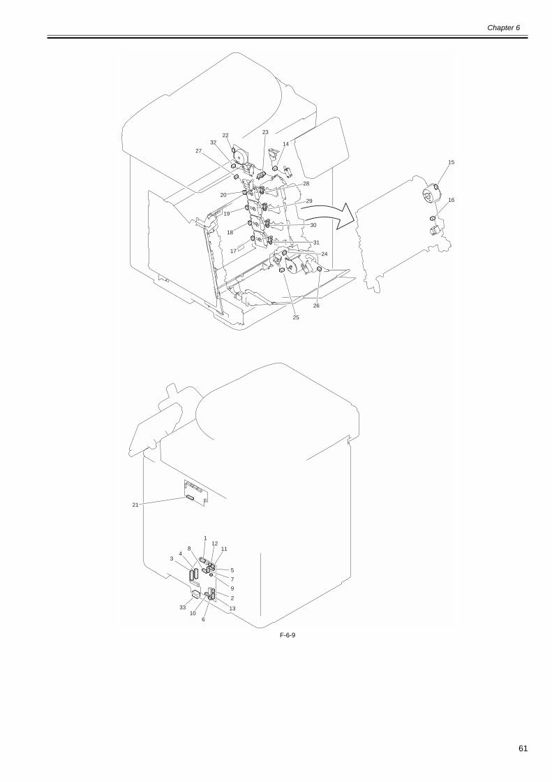
Chapter 6
61
F-6-9
21
22
28
29
30
31
24
14
15
16
23
26
25
32
27
20
19
18
17
2
13
610
33
1
84
3
1211
5
7
9
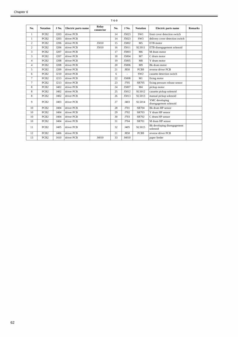
Chapter 6
62
T-6-9
No. Notation J No. Electric parts name Relay connector No. J No. Notation Electric parts name Remarks
1 PCB2 J203 driver PCB 14 J5023 SW1 front cover detection switch1 PCB2 J203 driver PCB 14 J5023 SW3 delivery cover detection switch2 PCB2 J206 driver PCB J5010 15 J5002 M5 ETB motor2 PCB2 J206 driver PCB J5010 16 J5011 SL5011 ETB disengagement solenoid3 PCB2 J207 driver PCB 17 J5003 M6 M drum motor3 PCB2 J207 driver PCB 18 J5004 M7 C drum motor4 PCB2 J208 driver PCB 19 J5005 M8 Y drum motor4 PCB2 J208 driver PCB 20 J5006 M9 Bk drum motor5 PCB2 J209 driver PCB 21 J850 PCB9 reverse driver PCB6 PCB2 J210 driver PCB 6 - SW2 cassette detection switch7 PCB2 J213 driver PCB 22 J5008 M1 fixing motor7 PCB2 J213 driver PCB 23 J705 SR705 fixing pressure release sensor8 PCB2 J402 driver PCB 24 J5007 M4 pickup motor8 PCB2 J402 driver PCB 25 J5012 SL5012 cassette pickup solenoid8 PCB2 J402 driver PCB 26 J5013 SL5013 manual pickup solenoid
9 PCB2 J403 driver PCB 27 J403 SL5014 YMC developing disengagement solenoid
10 PCB2 J404 driver PCB 28 J701 SR704 Bk drum HP sensor10 PCB2 J404 driver PCB 29 J702 SR703 Y drum HP sensor10 PCB2 J404 driver PCB 30 J703 SR702 C drum HP sensor10 PCB2 J404 driver PCB 31 J704 SR701 M drum HP sensor
11 PCB2 J405 driver PCB 32 J405 SL5015 Bk developing disengagement solenoid
12 PCB2 J406 driver PCB 21 J850 PCB9 reverse driver PCB13 PCB2 J410 driver PCB J4010 33 J4010 paper feeder

Chapter 6
63
F-6-10
2826
6927
70
12
1514
1611
2419
18
22
13
233
34
7973
8081
64
7176
82
57
10
62
13
23
32
31
30
2117
20
5
74
6
8
7
4
9
75
29
25
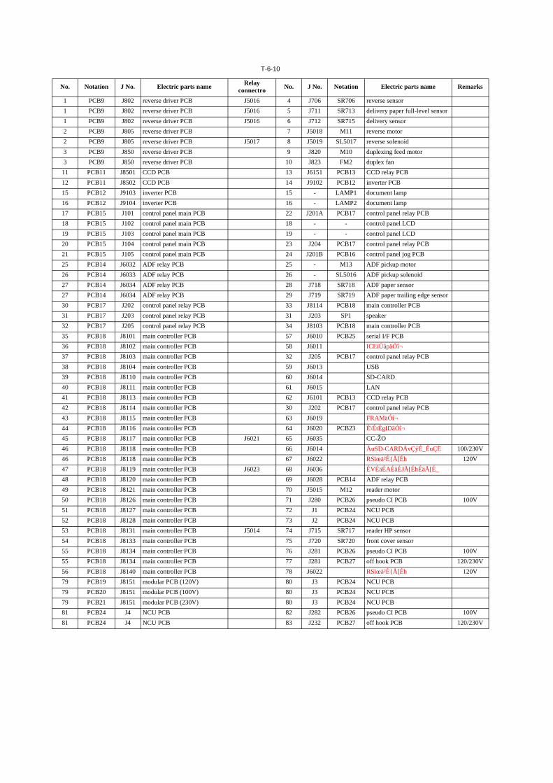
T-6-10
No. Notation J No. Electric parts name Relay connectro No. J No. Notation Electric parts name Remarks
1 PCB9 J802 reverse driver PCB J5016 4 J706 SR706 reverse sensor1 PCB9 J802 reverse driver PCB J5016 5 J711 SR713 delivery paper full-level sensor1 PCB9 J802 reverse driver PCB J5016 6 J712 SR715 delivery sensor2 PCB9 J805 reverse driver PCB 7 J5018 M11 reverse motor2 PCB9 J805 reverse driver PCB J5017 8 J5019 SL5017 reverse solenoid3 PCB9 J850 reverse driver PCB 9 J820 M10 duplexing feed motor3 PCB9 J850 reverse driver PCB 10 J823 FM2 duplex fan11 PCB11 J8501 CCD PCB 13 J6151 PCB13 CCD relay PCB12 PCB11 J8502 CCD PCB 14 J9102 PCB12 inverter PCB15 PCB12 J9103 inverter PCB 15 - LAMP1 document lamp16 PCB12 J9104 inverter PCB 16 - LAMP2 document lamp17 PCB15 J101 control panel main PCB 22 J201A PCB17 control panel relay PCB18 PCB15 J102 control panel main PCB 18 - - control panel LCD19 PCB15 J103 control panel main PCB 19 - - control panel LCD20 PCB15 J104 control panel main PCB 23 J204 PCB17 control panel relay PCB21 PCB15 J105 control panel main PCB 24 J201B PCB16 control panel jog PCB25 PCB14 J6032 ADF relay PCB 25 - M13 ADF pickup motor26 PCB14 J6033 ADF relay PCB 26 - SL5016 ADF pickup solenoid27 PCB14 J6034 ADF relay PCB 28 J718 SR718 ADF paper sensor27 PCB14 J6034 ADF relay PCB 29 J719 SR719 ADF paper trailing edge sensor30 PCB17 J202 control panel relay PCB 33 J8114 PCB18 main controller PCB31 PCB17 J203 control panel relay PCB 31 J203 SP1 speaker32 PCB17 J205 control panel relay PCB 34 J8103 PCB18 main controller PCB35 PCB18 J8101 main controller PCB 57 J6010 PCB25 serial I/F PCB36 PCB18 J8102 main controller PCB 58 J6011 ICEíÜåpäÓî¬37 PCB18 J8103 main controller PCB 32 J205 PCB17 control panel relay PCB38 PCB18 J8104 main controller PCB 59 J6013 USB39 PCB18 J8110 main controller PCB 60 J6014 SD-CARD40 PCB18 J8111 main controller PCB 61 J6015 LAN41 PCB18 J8113 main controller PCB 62 J6101 PCB13 CCD relay PCB42 PCB18 J8114 main controller PCB 30 J202 PCB17 control panel relay PCB43 PCB18 J8115 main controller PCB 63 J6019 FRAMäÓî¬44 PCB18 J8116 main controller PCB 64 J6020 PCB23 É\ÉtÉgIDäÓî¬45 PCB18 J8117 main controller PCB J6021 65 J6035 CC-ŽO46 PCB18 J8118 main controller PCB 66 J6014 ÅuSD-CARDÅvÇýÉ_ÉuÇË 100/230V46 PCB18 J8118 main controller PCB 67 J6022 RSïœä²É{Å[Éh 120V47 PCB18 J8119 main controller PCB J6023 68 J6036 ÉVÉäÉAÉãÉJÅ[ÉhÉäÅ[É_48 PCB18 J8120 main controller PCB 69 J6028 PCB14 ADF relay PCB49 PCB18 J8121 main controller PCB 70 J5015 M12 reader motor50 PCB18 J8126 main controller PCB 71 J280 PCB26 pseudo CI PCB 100V51 PCB18 J8127 main controller PCB 72 J1 PCB24 NCU PCB52 PCB18 J8128 main controller PCB 73 J2 PCB24 NCU PCB53 PCB18 J8131 main controller PCB J5014 74 J715 SR717 reader HP sensor54 PCB18 J8133 main controller PCB 75 J720 SR720 front cover sensor55 PCB18 J8134 main controller PCB 76 J281 PCB26 pseudo CI PCB 100V55 PCB18 J8134 main controller PCB 77 J281 PCB27 off hook PCB 120/230V56 PCB18 J8140 main controller PCB 78 J6022 RSïœä²É{Å[Éh 120V79 PCB19 J8151 modular PCB (120V) 80 J3 PCB24 NCU PCB79 PCB20 J8151 modular PCB (100V) 80 J3 PCB24 NCU PCB79 PCB21 J8151 modular PCB (230V) 80 J3 PCB24 NCU PCB81 PCB24 J4 NCU PCB 82 J282 PCB26 pseudo CI PCB 100V81 PCB24 J4 NCU PCB 83 J232 PCB27 off hook PCB 120/230V
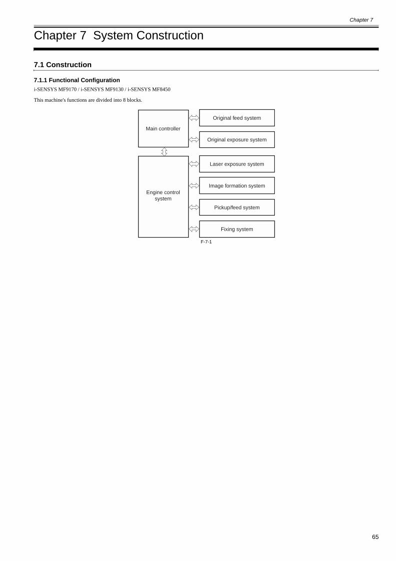
Chapter 7
65
Chapter 7 System Construction
7.1 Construction
7.1.1 Functional Configuration0019-5071
i-SENSYS MF9170 / i-SENSYS MF9130 / i-SENSYS MF8450
This machine's functions are divided into 8 blocks.
F-7-1
Engine controlsystem
Main controller
Original feed system
Original exposure system
Laser exposure system
Image formation system
Pickup/feed system
Fixing system
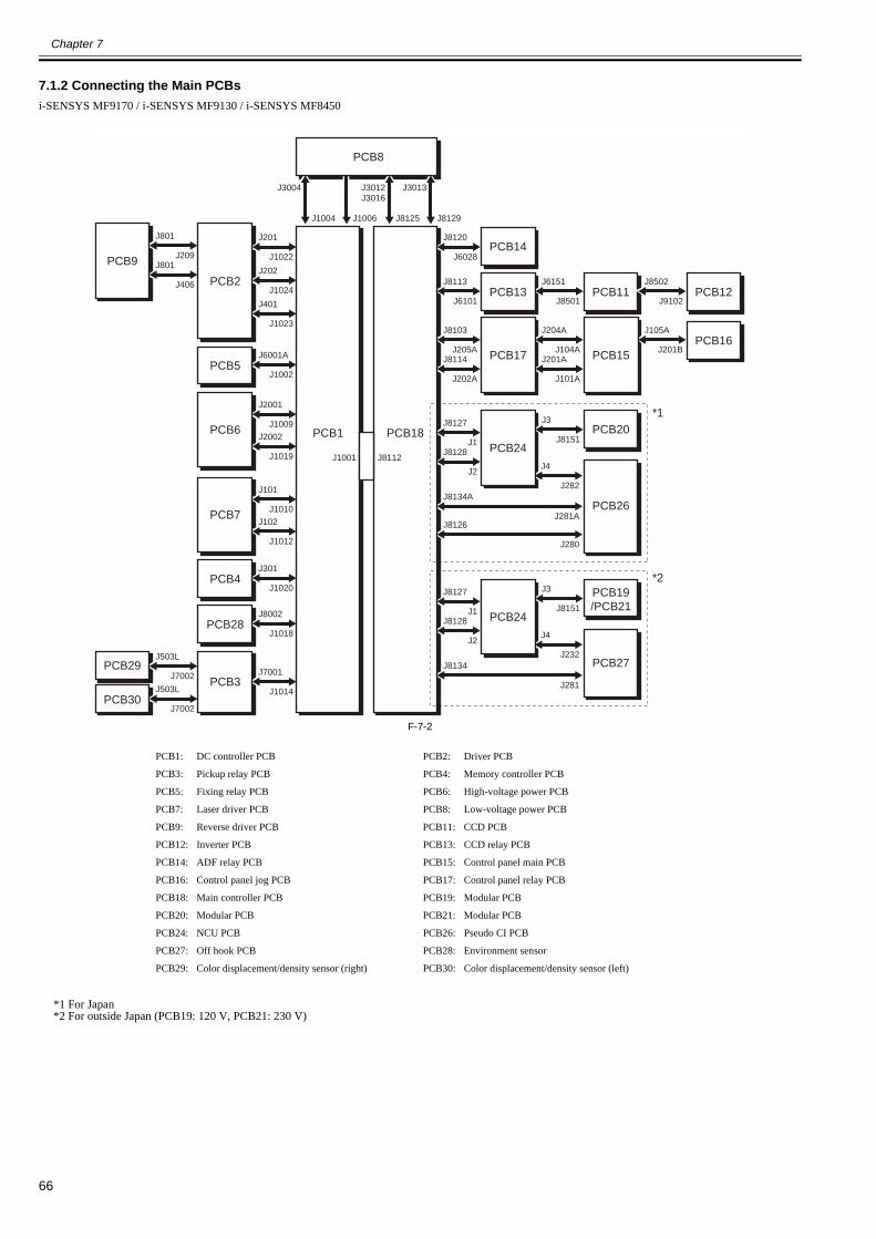
Chapter 7
66
7.1.2 Connecting the Main PCBs0019-9009
i-SENSYS MF9170 / i-SENSYS MF9130 / i-SENSYS MF8450
F-7-2
*1 For Japan*2 For outside Japan (PCB19: 120 V, PCB21: 230 V)
PCB1: DC controller PCB PCB2: Driver PCB
PCB3: Pickup relay PCB PCB4: Memory controller PCB
PCB5: Fixing relay PCB PCB6: High-voltage power PCB
PCB7: Laser driver PCB PCB8: Low-voltage power PCB
PCB9: Reverse driver PCB PCB11: CCD PCB
PCB12: Inverter PCB PCB13: CCD relay PCB
PCB14: ADF relay PCB PCB15: Control panel main PCB
PCB16: Control panel jog PCB PCB17: Control panel relay PCB
PCB18: Main controller PCB PCB19: Modular PCB
PCB20: Modular PCB PCB21: Modular PCB
PCB24: NCU PCB PCB26: Pseudo CI PCB
PCB27: Off hook PCB PCB28: Environment sensor
PCB29: Color displacement/density sensor (right) PCB30: Color displacement/density sensor (left)
J201
J1022
J202
J1024
J401
J1023
PCB2
J6001A
J1002
J2002
J1019
J2001
J1009
PCB5
J8120
J6028
J8129
J3013
J8125
J3012J3016
J1006J1004
J3004
J8113
J6101
PCB14
J6151
J8501PCB11
J3
J8151PCB20
PCB26
J8502
J9102PCB12
J105A
J201BPCB16
J301
J1020PCB4
J503L
J7002PCB29
J503L
J7002PCB30
J8002
J1018
J7001
J1014
PCB28
PCB3
PCB6
J8114
J202A
J8103
J205AJ201A
J101A
J204A
J104A PCB15
J8128
J2J4
J282J8134A
J281AJ8126
J280
J8127
J1 PCB24
J3
J8151
PCB19/PCB21
PCB27
J8128
J2J4
J232J8134
J281
J8127
J1 PCB24
J801
J406
J801
J209PCB9
J102
J1012
J101
J1010PCB7
PCB18
PCB8
PCB1
PCB13
PCB17
J8112J1001
*1
*2
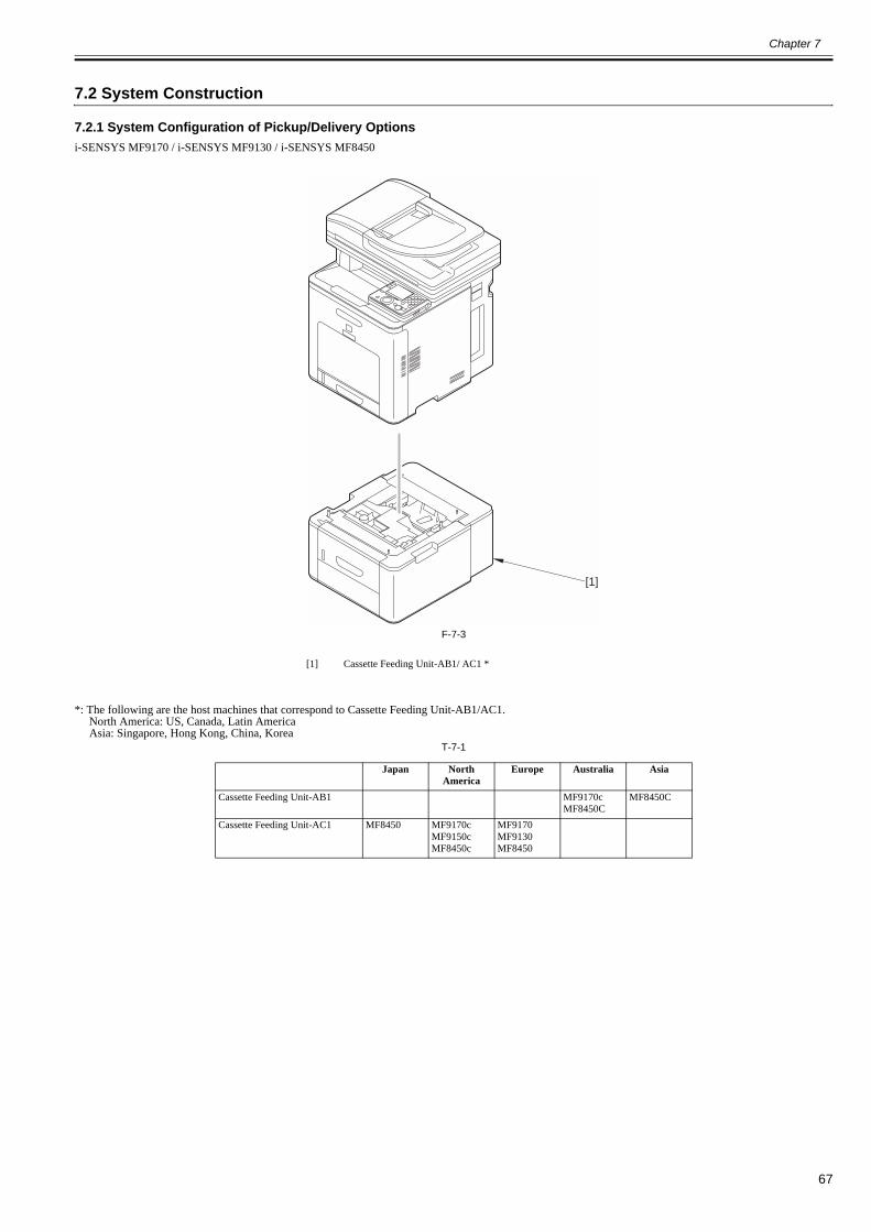
Chapter 7
67
7.2 System Construction
7.2.1 System Configuration of Pickup/Delivery Options0020-7747
i-SENSYS MF9170 / i-SENSYS MF9130 / i-SENSYS MF8450
F-7-3
*: The following are the host machines that correspond to Cassette Feeding Unit-AB1/AC1.North America: US, Canada, Latin AmericaAsia: Singapore, Hong Kong, China, Korea
T-7-1
[1] Cassette Feeding Unit-AB1/ AC1 *
Japan North America
Europe Australia Asia
Cassette Feeding Unit-AB1 MF9170cMF8450C
MF8450C
Cassette Feeding Unit-AC1 MF8450 MF9170cMF9150cMF8450c
MF9170MF9130MF8450
[1]

Chapter 7
68
7.2.2 System Configuration of Print/Send Options0020-1285
i-SENSYS MF9170 / i-SENSYS MF9130 / i-SENSYS MF8450
F-7-4
7.3 Product Specifications
7.3.1 Main Body Specifications0020-1287
i-SENSYS MF9170 / i-SENSYS MF9130
[1] HANDSET-J1 *
* For MF9170 (Europe) / MF8450 (Europe) / MF8450C (Singapore) only
Super G3FAX Board AB1 is required to attach Handset J1. (There is a model including Super G3FAX Board AB1 as standard equipment.)
Copyboard Fixed copyboardBody DesktopLight source type Cold-cathode tubeLens type Fixed focal length lensPhotosensitive medium OPC drum (24 mm dia)Image reading method CCDExposure method 2-polygon 4-laser (2-beam/laser)Charging method Roller chargingDevelopment method Contact developmentAttraction method Roller attractionTransfer method Direct transfer (ETB: Electrostatic Transportation Belt)Separation method Curvature separationCassette pickup method Duplo (Center line)Multifeeder pickup method Duplo (Center line)Drum cleaning method Cleaning bladeTransfer cleaning method Electrostatic cleaningFixing method On-demand fixingDelivery method Face downToner level detection function ProvidedToner type Nonmagnetic 1-component tonerToner supply type All-in-one cartridgeToner save mode ProvidedOriginal type Sheet, book, 3-D object (Up to 2kg)Maximum original size A4/ LTR/ LGLOriginal size detection function Not providedReproduction ratio 50% to 200% (incremented by 1%), 50%, 70%, 81%, 86%, 100%, 115%,
122%, 141%, 200%Warm-up time Less than approx. 60 sec
(Temperature: 20 degC, Humidity: 65%, from when the machine isturned on to when the standby screen is displayed)
[1]

Chapter 7
69
Print area At printingPaper other than envelope: Inside of the circumference of 5 mmEnvelope: Inside of the circumference of 10 mmAt copyingInside of the lead edge of 5 mm, both sides of 3 mm, and trailing edge of5 mmAt the time of printing a received messageInside of the lead edge of 5 mm, both sides of 3 mm, and trailing edge of6 mm
Maximum non-image width (main scanning direction)
Less than +/- 0.5%(At stream reading: Not specified)
Maximum non-image width (sub scanning direction)
Less than +/- 0.5%(At stream reading: Less than +/- 1.0%)
Image margin (leading edge) 0 +/- 1.5 mmImage margin (left/right) Left edge: 0 +/- 1.5 mm
(The right side is not detected.)Non-image width (leading edge) Less than 5.0 +/- 2.0 mm (When ADF is used (incl. stream reading): Less
than 5.0 +/- 2.0 mm)Non-image width (left/right) Left edge: Less than 3.0 +/- 2.0 mm (When ADF is used (incl. stream
reading): Less than 3.0 +/- 2.0 mm)Gradation 256 gradationReading resolution 600 x 600 dpiReading speed Fixed reading: Not specified
Stream reading: Single-sided: 20.8ipm/LTR (600dpi), 19.7ipm/A4(600dpi)Double-sided: Approx. 7ipm
Copying resolution 600 x 600dpi (ADF, copyboard)Printing resolution 600 x 600 dpiFirst copy time (See "Print Speed")
Fixed reading: Less than 12.5 sec (A4/LTR)Stream reading: Less than 18.5 sec (A4/LTR)
First print time Less than 12.5 secPrint speed (See "Print Speed")Print speed (A4) 21 cpmPrint speed(LTR) 22 cpmPaper type (See "Paper Type")Cassette paper size A4, B5, A5Multifeeder paper size A4, B5, A5, User-defined sizeCassette paper type Plain paper, Recycled paper, Colored paper, Thick paper, Rough paperMultifeeder tray paper type Plain paper, Recycled paper, Colored paper, Thick paper, Transparency,
Label, Rough paper, Postcard, Double postal card, EnvelopeCassette capacity Paper cassette: 250 sheets Cassette Feeding Unit-AB1/ AC1 (optional):
500 sheets (80g/m2)
Multifeeder tray capacity 100 sheetsAuto 2-sided printing ProvidedDuplex method Automatic double-sided printingDelivery tray stack 250 sheets (64 to 80g/m2)Continuous reproduction 1 to 99 sheetsMemory Main Unit RAM:
384MB/512MBHard disk No (without options)Sleep mode ProvidedOperating environment (temperature range)
10 to 30 degC
Operating environment (humidity range)
Humidity equivalent to 10 to 80%
Noise At standby:- Less than 43dB (Sound power level)
At copying:- B&W: 66.35dB- Color: 67.3dB
Power supply rating Rated input voltage: 100 to 127V (100V model)/220 to 240V (200Vmodel)Rated input frequency: 50/60Hz
Power consumption (maximum) Less than 929W (Main unit only)Less than 949W (When Cassette Unit AB1/AC1 (optional) is installed)
Power consumption At standby: Less than 28WAt sleep mode: Less than 1W (100V model), Less than 1.2W (200Vmodel)
Ozone At initial use: Less than 0.01ppm, After service life: Less than 0.035ppmB&W: 1.5mg/hrColor: 3.0mg/hr
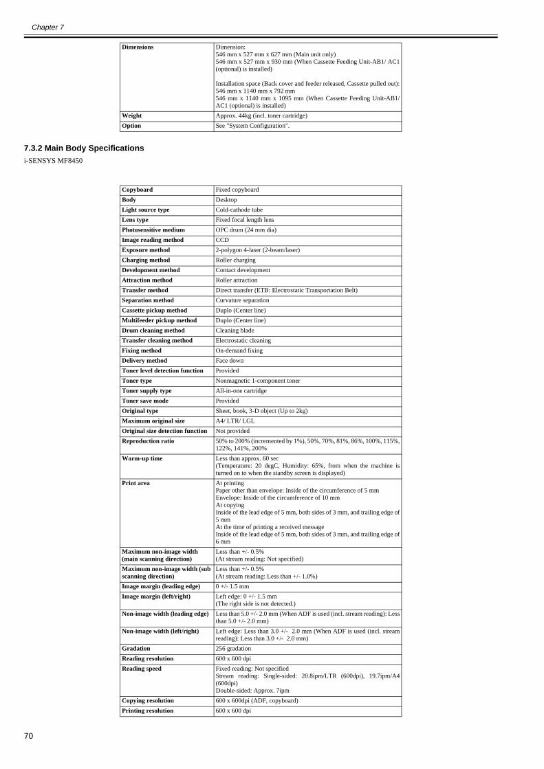
Chapter 7
70
7.3.2 Main Body Specifications0020-1288
i-SENSYS MF8450
Dimensions Dimension:546 mm x 527 mm x 627 mm (Main unit only)546 mm x 527 mm x 930 mm (When Cassette Feeding Unit-AB1/ AC1(optional) is installed)
Installation space (Back cover and feeder released, Cassette pulled out):546 mm x 1140 mm x 792 mm546 mm x 1140 mm x 1095 mm (When Cassette Feeding Unit-AB1/AC1 (optional) is installed)
Weight Approx. 44kg (incl. toner cartridge)Option See "System Configuration".
Copyboard Fixed copyboardBody DesktopLight source type Cold-cathode tubeLens type Fixed focal length lensPhotosensitive medium OPC drum (24 mm dia)Image reading method CCDExposure method 2-polygon 4-laser (2-beam/laser)Charging method Roller chargingDevelopment method Contact developmentAttraction method Roller attractionTransfer method Direct transfer (ETB: Electrostatic Transportation Belt)Separation method Curvature separationCassette pickup method Duplo (Center line)Multifeeder pickup method Duplo (Center line)Drum cleaning method Cleaning bladeTransfer cleaning method Electrostatic cleaningFixing method On-demand fixingDelivery method Face downToner level detection function ProvidedToner type Nonmagnetic 1-component tonerToner supply type All-in-one cartridgeToner save mode ProvidedOriginal type Sheet, book, 3-D object (Up to 2kg)Maximum original size A4/ LTR/ LGLOriginal size detection function Not providedReproduction ratio 50% to 200% (incremented by 1%), 50%, 70%, 81%, 86%, 100%, 115%,
122%, 141%, 200%Warm-up time Less than approx. 60 sec
(Temperature: 20 degC, Humidity: 65%, from when the machine isturned on to when the standby screen is displayed)
Print area At printingPaper other than envelope: Inside of the circumference of 5 mmEnvelope: Inside of the circumference of 10 mmAt copyingInside of the lead edge of 5 mm, both sides of 3 mm, and trailing edge of5 mmAt the time of printing a received messageInside of the lead edge of 5 mm, both sides of 3 mm, and trailing edge of6 mm
Maximum non-image width (main scanning direction)
Less than +/- 0.5%(At stream reading: Not specified)
Maximum non-image width (sub scanning direction)
Less than +/- 0.5%(At stream reading: Less than +/- 1.0%)
Image margin (leading edge) 0 +/- 1.5 mmImage margin (left/right) Left edge: 0 +/- 1.5 mm
(The right side is not detected.)Non-image width (leading edge) Less than 5.0 +/- 2.0 mm (When ADF is used (incl. stream reading): Less
than 5.0 +/- 2.0 mm)Non-image width (left/right) Left edge: Less than 3.0 +/- 2.0 mm (When ADF is used (incl. stream
reading): Less than 3.0 +/- 2.0 mm)Gradation 256 gradationReading resolution 600 x 600 dpiReading speed Fixed reading: Not specified
Stream reading: Single-sided: 20.8ipm/LTR (600dpi), 19.7ipm/A4(600dpi)Double-sided: Approx. 7ipm
Copying resolution 600 x 600dpi (ADF, copyboard)Printing resolution 600 x 600 dpi
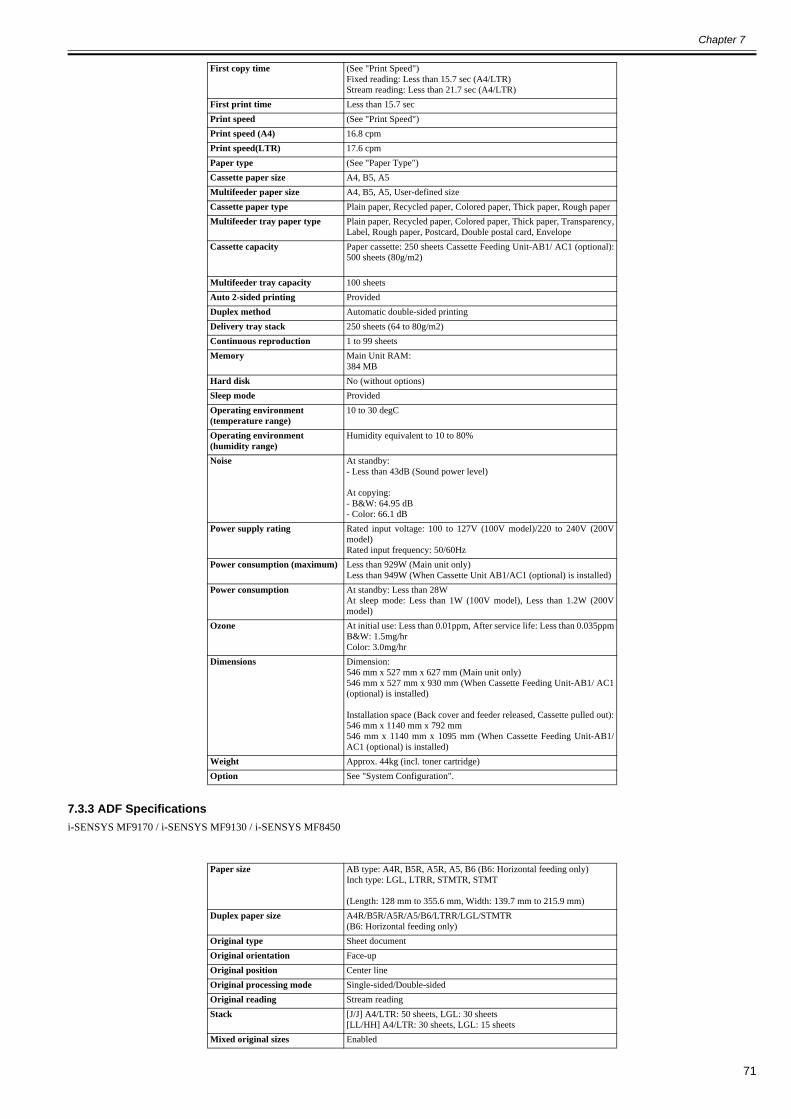
Chapter 7
71
7.3.3 ADF Specifications0020-0876
i-SENSYS MF9170 / i-SENSYS MF9130 / i-SENSYS MF8450
First copy time (See "Print Speed")Fixed reading: Less than 15.7 sec (A4/LTR)Stream reading: Less than 21.7 sec (A4/LTR)
First print time Less than 15.7 secPrint speed (See "Print Speed")Print speed (A4) 16.8 cpmPrint speed(LTR) 17.6 cpmPaper type (See "Paper Type")Cassette paper size A4, B5, A5Multifeeder paper size A4, B5, A5, User-defined sizeCassette paper type Plain paper, Recycled paper, Colored paper, Thick paper, Rough paperMultifeeder tray paper type Plain paper, Recycled paper, Colored paper, Thick paper, Transparency,
Label, Rough paper, Postcard, Double postal card, EnvelopeCassette capacity Paper cassette: 250 sheets Cassette Feeding Unit-AB1/ AC1 (optional):
500 sheets (80g/m2)
Multifeeder tray capacity 100 sheetsAuto 2-sided printing ProvidedDuplex method Automatic double-sided printingDelivery tray stack 250 sheets (64 to 80g/m2)Continuous reproduction 1 to 99 sheetsMemory Main Unit RAM:
384 MBHard disk No (without options)Sleep mode ProvidedOperating environment (temperature range)
10 to 30 degC
Operating environment (humidity range)
Humidity equivalent to 10 to 80%
Noise At standby:- Less than 43dB (Sound power level)
At copying:- B&W: 64.95 dB- Color: 66.1 dB
Power supply rating Rated input voltage: 100 to 127V (100V model)/220 to 240V (200Vmodel)Rated input frequency: 50/60Hz
Power consumption (maximum) Less than 929W (Main unit only)Less than 949W (When Cassette Unit AB1/AC1 (optional) is installed)
Power consumption At standby: Less than 28WAt sleep mode: Less than 1W (100V model), Less than 1.2W (200Vmodel)
Ozone At initial use: Less than 0.01ppm, After service life: Less than 0.035ppmB&W: 1.5mg/hrColor: 3.0mg/hr
Dimensions Dimension:546 mm x 527 mm x 627 mm (Main unit only)546 mm x 527 mm x 930 mm (When Cassette Feeding Unit-AB1/ AC1(optional) is installed)
Installation space (Back cover and feeder released, Cassette pulled out):546 mm x 1140 mm x 792 mm546 mm x 1140 mm x 1095 mm (When Cassette Feeding Unit-AB1/AC1 (optional) is installed)
Weight Approx. 44kg (incl. toner cartridge)Option See "System Configuration".
Paper size AB type: A4R, B5R, A5R, A5, B6 (B6: Horizontal feeding only)Inch type: LGL, LTRR, STMTR, STMT
(Length: 128 mm to 355.6 mm, Width: 139.7 mm to 215.9 mm)Duplex paper size A4R/B5R/A5R/A5/B6/LTRR/LGL/STMTR
(B6: Horizontal feeding only)Original type Sheet documentOriginal orientation Face-upOriginal position Center lineOriginal processing mode Single-sided/Double-sidedOriginal reading Stream readingStack [J/J] A4/LTR: 50 sheets, LGL: 30 sheets
[LL/HH] A4/LTR: 30 sheets, LGL: 15 sheetsMixed original sizes Enabled

Chapter 7
72
Original AE detection Provided
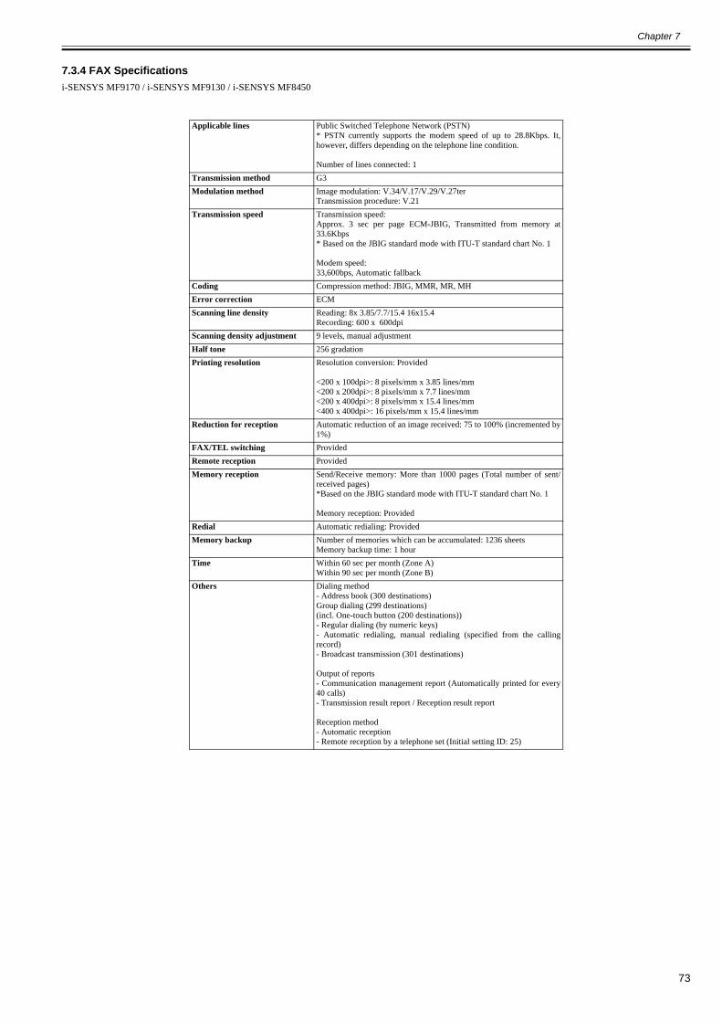
Chapter 7
73
7.3.4 FAX Specifications0020-0877
i-SENSYS MF9170 / i-SENSYS MF9130 / i-SENSYS MF8450
Applicable lines Public Switched Telephone Network (PSTN)* PSTN currently supports the modem speed of up to 28.8Kbps. It,however, differs depending on the telephone line condition.
Number of lines connected: 1Transmission method G3Modulation method Image modulation: V.34/V.17/V.29/V.27ter
Transmission procedure: V.21Transmission speed Transmission speed:
Approx. 3 sec per page ECM-JBIG, Transmitted from memory at33.6Kbps* Based on the JBIG standard mode with ITU-T standard chart No. 1
Modem speed:33,600bps, Automatic fallback
Coding Compression method: JBIG, MMR, MR, MHError correction ECMScanning line density Reading: 8x 3.85/7.7/15.4 16x15.4
Recording: 600 x 600dpiScanning density adjustment 9 levels, manual adjustmentHalf tone 256 gradationPrinting resolution Resolution conversion: Provided
<200 x 100dpi>: 8 pixels/mm x 3.85 lines/mm<200 x 200dpi>: 8 pixels/mm x 7.7 lines/mm<200 x 400dpi>: 8 pixels/mm x 15.4 lines/mm<400 x 400dpi>: 16 pixels/mm x 15.4 lines/mm
Reduction for reception Automatic reduction of an image received: 75 to 100% (incremented by1%)
FAX/TEL switching ProvidedRemote reception ProvidedMemory reception Send/Receive memory: More than 1000 pages (Total number of sent/
received pages)*Based on the JBIG standard mode with ITU-T standard chart No. 1
Memory reception: ProvidedRedial Automatic redialing: ProvidedMemory backup Number of memories which can be accumulated: 1236 sheets
Memory backup time: 1 hourTime Within 60 sec per month (Zone A)
Within 90 sec per month (Zone B)Others Dialing method
- Address book (300 destinations)Group dialing (299 destinations)(incl. One-touch button (200 destinations))- Regular dialing (by numeric keys)- Automatic redialing, manual redialing (specified from the callingrecord)- Broadcast transmission (301 destinations)
Output of reports- Communication management report (Automatically printed for every40 calls)- Transmission result report / Reception result report
Reception method- Automatic reception- Remote reception by a telephone set (Initial setting ID: 25)

Chapter 7
74
7.4 Function List
7.4.1 Print Speed0019-4886
i-SENSYS MF9170 / i-SENSYS MF9130
First copy timeThe following standard is defined with "35 seconds" after printing 90 sheets of A4-size plain paper in the mode of "1 vs. multiple copies" *1 at copyboard reading.(Unit: second)
T-7-2
Print speed(Unit: #Sheets/minute)
T-7-3
SizeMode/Pickup positionSingle-sided printing
Cassette/Optional cassette Manual feed tray
Plain paperA4R 12.5 12.5LGL 16.3 16.3
LTRR 12.5 12.5
Thick paperA4R - 15.7LGL - -
LTRR - 15.7
Size
Mode/Pickup position1 vs. multiple copies *1
(Fixed reading)1 vs. 1 copy *1
(Stream reading)Single-sided Double-sided Single-sided Double-sided
Cassette/Optional cassette
Manual feed tray
Cassette/Optional cassette
Manual feed tray
Cassette/Optional cassette
Manual feed tray
Cassette/Optional cassette
Manual feed tray
Plain paper
A4R 20.9 20.9 10 10 19.7 19.7 7 7
LGL 17.9 17.9 5 5 17.9 17.9 5 5
LTRR 22.0 22.0 11 11 20.8 20.8 7 7
Thick paper
A4R 16.8 16.8 8.4 8.4 16.8 16.8 7 7
LGL 14.3 14.3 4 4 14.3 14.3 4 4
LTRR 17.6 17.6 8.8 8.8 17.6 17.6 7 7
Transparency *2 - 3.6 to 1.8 - - - 3.6 to 1.8 - -Postcard *2 - 10.1 to 2.5 - - - 10.1 to 2.5 - -Envelopes - 3.2 - - - 3.2 - -
*1: 1 vs. multiple copies:1 vs. 1 copy:
For example, make 10 copies of one sheet of document.For example, make one copy of one sheet of document.
*2: At the continuous print, printing speed may decelerate depending on the conditions.
The print speed indicated above may vary depending on the product environment, paper type, and paper size, etc.
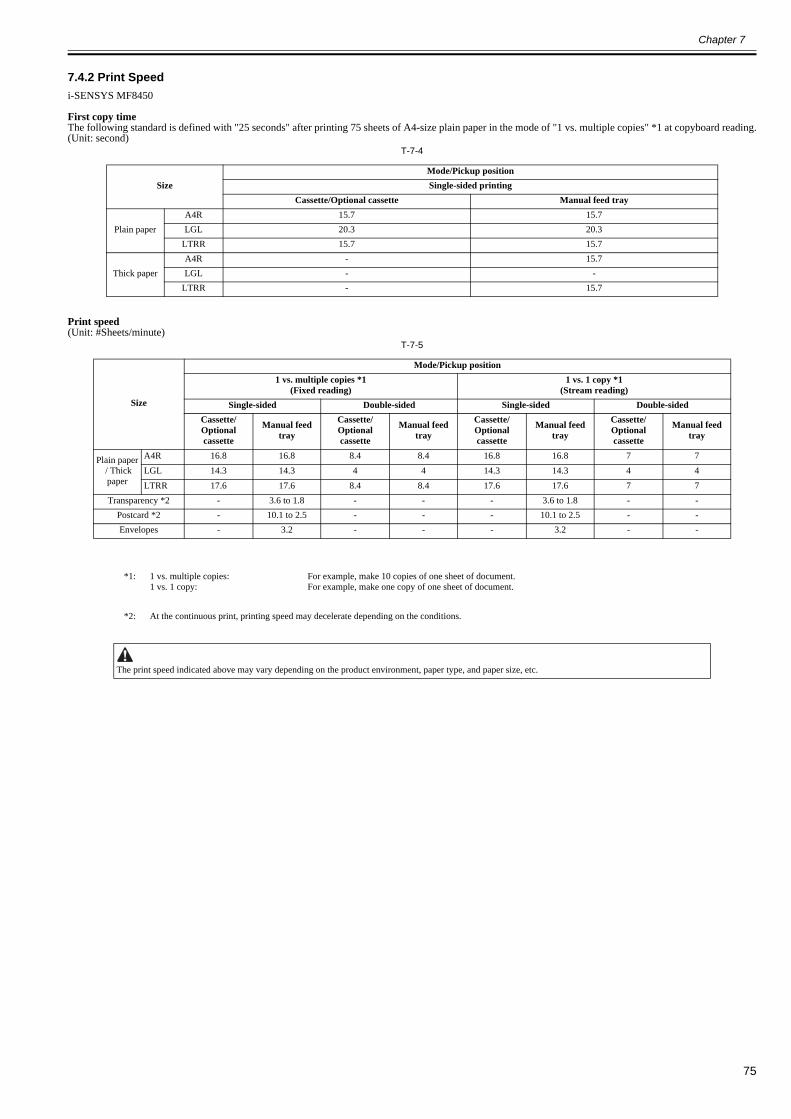
Chapter 7
75
7.4.2 Print Speed0020-0210
i-SENSYS MF8450
First copy timeThe following standard is defined with "25 seconds" after printing 75 sheets of A4-size plain paper in the mode of "1 vs. multiple copies" *1 at copyboard reading.(Unit: second)
T-7-4
Print speed(Unit: #Sheets/minute)
T-7-5
SizeMode/Pickup positionSingle-sided printing
Cassette/Optional cassette Manual feed tray
Plain paperA4R 15.7 15.7LGL 20.3 20.3
LTRR 15.7 15.7
Thick paperA4R - 15.7LGL - -
LTRR - 15.7
Size
Mode/Pickup position1 vs. multiple copies *1
(Fixed reading)1 vs. 1 copy *1
(Stream reading)Single-sided Double-sided Single-sided Double-sided
Cassette/Optional cassette
Manual feed tray
Cassette/Optional cassette
Manual feed tray
Cassette/Optional cassette
Manual feed tray
Cassette/Optional cassette
Manual feed tray
Plain paper / Thick paper
A4R 16.8 16.8 8.4 8.4 16.8 16.8 7 7LGL 14.3 14.3 4 4 14.3 14.3 4 4LTRR 17.6 17.6 8.4 8.4 17.6 17.6 7 7
Transparency *2 - 3.6 to 1.8 - - - 3.6 to 1.8 - -Postcard *2 - 10.1 to 2.5 - - - 10.1 to 2.5 - -Envelopes - 3.2 - - - 3.2 - -
*1: 1 vs. multiple copies:1 vs. 1 copy:
For example, make 10 copies of one sheet of document.For example, make one copy of one sheet of document.
*2: At the continuous print, printing speed may decelerate depending on the conditions.
The print speed indicated above may vary depending on the product environment, paper type, and paper size, etc.
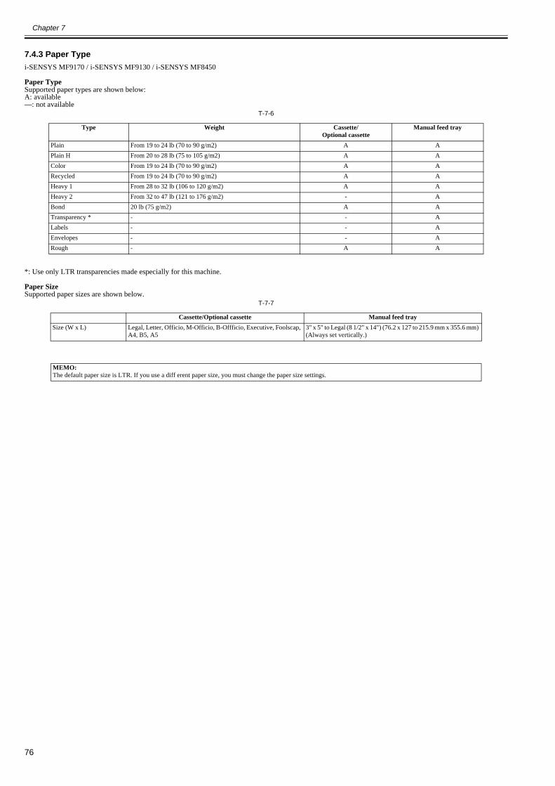
Chapter 7
76
7.4.3 Paper Type0020-5103
i-SENSYS MF9170 / i-SENSYS MF9130 / i-SENSYS MF8450
Paper TypeSupported paper types are shown below:A: available—: not available
T-7-6
*: Use only LTR transparencies made especially for this machine.
Paper SizeSupported paper sizes are shown below.
T-7-7
Type Weight Cassette/Optional cassette
Manual feed tray
Plain From 19 to 24 lb (70 to 90 g/m2) A APlain H From 20 to 28 lb (75 to 105 g/m2) A AColor From 19 to 24 lb (70 to 90 g/m2) A ARecycled From 19 to 24 lb (70 to 90 g/m2) A AHeavy 1 From 28 to 32 lb (106 to 120 g/m2) A AHeavy 2 From 32 to 47 lb (121 to 176 g/m2) - ABond 20 lb (75 g/m2) A ATransparency * - - ALabels - - AEnvelopes - - ARough - A A
Cassette/Optional cassette Manual feed traySize (W x L) Legal, Letter, Officio, M-Officio, B-Offficio, Executive, Foolscap,
A4, B5, A53" x 5" to Legal (8 1/2" x 14") (76.2 x 127 to 215.9 mm x 355.6 mm) (Always set vertically.)
MEMO:The default paper size is LTR. If you use a diff erent paper size, you must change the paper size settings.

Chapter 8
77
Chapter 8 Upgrading
8.1 Upgrading
8.1.1 Overview of Upgrade0019-5082
i-SENSYS MF9170 / i-SENSYS MF9130 / i-SENSYS MF8450
To upgrade this machine, download the firmware from PC to the machine with using the user support tool (hereinafter called UST).ÅöÉCÉâÉXÉgÅi031-MNT-UPGD-0001ÅjçÏê¨íÜÅö


Aug 22 2008
