metropolis adm (universal shelf) - nokia networks of hazard statements ... 6 system planning and...
TRANSCRIPT
Metropolis ® ADM (Universal shelf)Release 5.2Applications and Planning Guide
365-312-841R5.2CC109640607
Issue 1December 2006
Lucent Technologies - ProprietaryThis document contains proprietary information of Lucent Technologies and
is not to be disclosed or used except in accordance with applicable agreements.
Copyright © 2006 Lucent TechnologiesUnpublished and Not for Publication
All Rights Reserved
See notice on first age

This material is protected by the copyright and trade secret laws of the United States and other countries. It may not be reproduced,distributed, or altered in any fashion by any entity (either internal or external to Lucent Technologies), except in accordance with applicableagreements, contracts or licensing, without the express written consent of Lucent Technologies and the business management owner of thematerial.
Trademarks
All trademarks and service marks specified herein are owned by their respective companies.
Notice
Every effort has been made to ensure that the information in this document was complete and accurate at the time of printing. However,information is subject to change.
Hard Hat ™Linux ® Software Copyright Notices
Copyright 1999-2005.MONTAVISTA® SOFTWARE, INC..
Redistribution and use in source and binary forms, with or without modification, are permitted only as authorized by the GNU General PublicLicense (GPL version 2): http://www.fsf.org/licenses/licenses.html#GPL.
Linux® is a registered trademark of Linus Torvalds.
Hard Hat™Linux® is a trademark or registered trademark ofMONTAVISTA® SOFTWARE, INC..
Individual files and/or contributed packages may be copyright by other parties and their use subject to additional restrictions.
Additional information about Hart Hat Linux can be obtained at www.mvista.com/products/pro.
Declaration of Conformity
The Declaration of Conformity (DoC) for this product can be found in this document at“Conformity statements” (p. 9-5), or at:http://www.lucent.de/ecl.
WEEE directive
The Waste from Electrical and Electronic Equipment (WEEE) directivefor this product can be found in this document at“Eco-environmentalstatements” (p. 9-8).
Overview EMC/ESD Safety
The EMC/ESD boundary has been defined at rack/subrack level. The principle is based on the “Faraday Cage” theory. If there are doors, thenthe doors must be closed. With every rack/subrack an ESD (electrostatic discharge) earth socket and an ESD sticker are supplied. On the Rackframe ETSI an ESD bonding point for an ESD wrist strap is present. It is mounted in a way that it’s always accessible for installation, normaloperation and maintenance activity.
Wrist strap
The wrist strap must be worn when opening the subrack doors.
Electrostatic sensitive devices
The equipment described in this guide contains static sensitive devices. Electrostatic discharge precautions should be taken when operating orworking on this equipment.
Special handling precautions apply whenever installing or removing parts of the equipment include:
• leaving components or equipment in original packaging until required for use.
• removing plug-in units with previously discharged hands (e.g. using grounded wrist straps connected to the ESD bonding point on the cabinet).
• returning items for repair in suitable antistatic packaging.
Ordering information
The order number of this document is 365-312-841R5.2 (Issue 1).
Technical support
Please contact your Lucent Technologies Local Customer Support Team (LCS) for technical questions about the information in this document.
Information product support
To comment on this information product online, go tohttp://www.lucent-info.com/commentsor email your comments [email protected].
See notice on first age
Lucent Technologies - ProprietarySee notice on first page

Contents
About this information product
Purpose............................................................................................................................................................................................ xixi
Reason for reissue....................................................................................................................................................................... xixi
Safety information...................................................................................................................................................................... xixi
Intended audience...................................................................................................................................................................... xiixii
How to use this information product................................................................................................................................ xiixii
Conventions used..................................................................................................................................................................... xiiixiii
Related documentation........................................................................................................................................................... xivxiv
Related training........................................................................................................................................................................... xvxv
Customer Documentation Subnetwork Controller Related..................................................................................... xvxv
Documented feature set.......................................................................................................................................................... xvixvi
Intended use................................................................................................................................................................................ xvixvi
Optical safety ............................................................................................................................................................................. xvixvi
Technical Documentation....................................................................................................................................................... xxxx
How to order................................................................................................................................................................................ xxxx
How to comment........................................................................................................................................................................ xxxx
1 Introduction
Overview ...................................................................................................................................................................................... 1-11-1
Structure of hazard statements............................................................................................................................................ 1-21-2
Metropolis® ADM (Universal shelf) network solutions........................................................................................... 1-41-4
The optical networking products family......................................................................................................................... 1-71-7
Metropolis® ADM (Universal shelf) system description...................................................................................... 1-101-10
...................................................................................................................................................................................................................................365-312-841R5.2Issue 1, December 2006
Lucent Technologies - ProprietarySee notice on first page
iii

2 Features
Overview ...................................................................................................................................................................................... 2-12-1
Physical interfaces
Overview ...................................................................................................................................................................................... 2-32-3
Synchronous interfaces.......................................................................................................................................................... 2-42-4
Data interfaces........................................................................................................................................................................... 2-62-6
Timing interfaces...................................................................................................................................................................... 2-72-7
Operations interfaces............................................................................................................................................................... 2-82-8
Power interfaces and grounding......................................................................................................................................... 2-92-9
SDH Transmission features
Overview ................................................................................................................................................................................... 2-102-10
Cross-connection features................................................................................................................................................... 2-112-11
Ring protection....................................................................................................................................................................... 2-122-12
DNI .............................................................................................................................................................................................. 2-152-15
Line protection........................................................................................................................................................................ 2-162-16
Path protection........................................................................................................................................................................ 2-182-18
Ethernet features
Overview ................................................................................................................................................................................... 2-212-21
Ethernet over SDH................................................................................................................................................................ 2-222-22
Virtual concatenation............................................................................................................................................................ 2-292-29
Spanning tree protocol (STP)........................................................................................................................................... 2-342-34
GARP VLAN Registration Protocol (GVRP)............................................................................................................ 2-382-38
Ethernet over SDH applications...................................................................................................................................... 2-412-41
Operational modes................................................................................................................................................................. 2-482-48
Tagging modes........................................................................................................................................................................ 2-582-58
Link Pass Through................................................................................................................................................................ 2-632-63
Link aggregation.................................................................................................................................................................... 2-642-64
IGMP snooping....................................................................................................................................................................... 2-662-66
IEEE 802.3ah Operations, Administration and Maintenance (OAM).............................................................. 2-692-69
Contents
...................................................................................................................................................................................................................................
iv Lucent Technologies - ProprietarySee notice on first page
365-312-841R5.2Issue 1, December 2006

IEEE 802.3ah OAM interworking with MRV Fiber Driver................................................................................ 2-732-73
Static MAC Address Provisioning.................................................................................................................................. 2-742-74
Port provisioning.................................................................................................................................................................... 2-752-75
Quality of Service (QoS) overview................................................................................................................................ 2-802-80
Classification, queueing and scheduling...................................................................................................................... 2-842-84
Quality of Service provisioning....................................................................................................................................... 2-932-93
Performance monitoring...................................................................................................................................................... 2-952-95
Equipment features
Overview ................................................................................................................................................................................... 2-972-97
Equipment protection........................................................................................................................................................... 2-982-98
Optical interface modules................................................................................................................................................ 2-1012-101
Equipment reports............................................................................................................................................................... 2-1022-102
Synchronization and timing
Overview ................................................................................................................................................................................. 2-1032-103
Timing features.................................................................................................................................................................... 2-1042-104
Timing protection................................................................................................................................................................ 2-1052-105
Timing interface features................................................................................................................................................. 2-1062-106
Operations, Administration, Maintenance and Provisioning
Overview ................................................................................................................................................................................. 2-1072-107
Interfaces................................................................................................................................................................................. 2-1082-108
Monitoring and diagnostics features............................................................................................................................ 2-1102-110
3 Network topologies
Overview ...................................................................................................................................................................................... 3-13-1
Access/metro applications
Overview ...................................................................................................................................................................................... 3-33-3
Access/metro core networking............................................................................................................................................ 3-43-4
Application details
Overview ...................................................................................................................................................................................... 3-53-5
Contents
...................................................................................................................................................................................................................................365-312-841R5.2Issue 1, December 2006
Lucent Technologies - ProprietarySee notice on first page
v

Ethernet services - packets over SDH............................................................................................................................. 3-63-6
Metro access multi-ring node with LXC functionality.......................................................................................... 3-113-11
4 Product description
Overview ...................................................................................................................................................................................... 4-14-1
Concise system description.................................................................................................................................................. 4-24-2
Transmission architecture.................................................................................................................................................... 4-54-5
Switch function ......................................................................................................................................................................... 4-84-8
Shelf configurations.............................................................................................................................................................. 4-114-11
Circuit packs............................................................................................................................................................................ 4-244-24
Synchronization and timing............................................................................................................................................... 4-464-46
System control and management..................................................................................................................................... 4-544-54
Power .......................................................................................................................................................................................... 4-554-55
Cooling ....................................................................................................................................................................................... 4-564-56
5 Operations, administration, maintenance and provisioning
Overview ...................................................................................................................................................................................... 5-15-1
Operations
Overview ...................................................................................................................................................................................... 5-35-3
Visible alarm indicators......................................................................................................................................................... 5-45-4
ITM-CIT ...................................................................................................................................................................................... 5-75-7
Operations interfaces............................................................................................................................................................... 5-95-9
Administration
Overview ................................................................................................................................................................................... 5-115-11
Security ...................................................................................................................................................................................... 5-125-12
NE administration concept................................................................................................................................................. 5-135-13
Maintenance
Overview ................................................................................................................................................................................... 5-145-14
Maintenance signals.............................................................................................................................................................. 5-155-15
Loopbacks and tests.............................................................................................................................................................. 5-195-19
Contents
...................................................................................................................................................................................................................................
vi Lucent Technologies - ProprietarySee notice on first page
365-312-841R5.2Issue 1, December 2006

Protection and redundancy............................................................................................................................................... 5-225-22
Performance monitoring...................................................................................................................................................... 5-245-24
Reports ....................................................................................................................................................................................... 5-265-26
Orderwire ................................................................................................................................................................................. 5-295-29
Provisioning
Overview ................................................................................................................................................................................... 5-305-30
Introduction .............................................................................................................................................................................. 5-315-31
6 System planning and engineering
Overview ...................................................................................................................................................................................... 6-16-1
General planning information............................................................................................................................................. 6-26-2
Power planning.......................................................................................................................................................................... 6-36-3
Cooling equipment................................................................................................................................................................... 6-46-4
Environmental conditions.................................................................................................................................................... 6-56-5
Transmission capacity............................................................................................................................................................ 6-76-7
Port location rules.................................................................................................................................................................... 6-96-9
Metropolis® ADM (Universal shelf) core engineering......................................................................................... 6-146-14
Network synchronization.................................................................................................................................................... 6-166-16
Floor plan layout.................................................................................................................................................................... 6-186-18
7 Ordering
Overview ...................................................................................................................................................................................... 7-17-1
Ordering information.............................................................................................................................................................. 7-27-2
8 Product support
Overview ...................................................................................................................................................................................... 8-18-1
Installation services................................................................................................................................................................. 8-28-2
Engineering services............................................................................................................................................................... 8-48-4
Maintenance services.............................................................................................................................................................. 8-68-6
Technical support..................................................................................................................................................................... 8-88-8
Documentation support........................................................................................................................................................ 8-108-10
Contents
...................................................................................................................................................................................................................................365-312-841R5.2Issue 1, December 2006
Lucent Technologies - ProprietarySee notice on first page
vii

Training support..................................................................................................................................................................... 8-118-11
9 Quality and reliability
Overview ...................................................................................................................................................................................... 9-19-1
Quality
Overview ...................................................................................................................................................................................... 9-29-2
Lucent Technologies’ commitment to quality and reliability................................................................................ 9-39-3
Ensuring quality........................................................................................................................................................................ 9-49-4
Conformity statements........................................................................................................................................................... 9-59-5
Reliability specifications
Overview ................................................................................................................................................................................... 9-109-10
General specifications.......................................................................................................................................................... 9-119-11
Reliability program .............................................................................................................................................................. 9-129-12
Reliability specifications ................................................................................................................................................... 9-139-13
10 Technical specifications
Overview ................................................................................................................................................................................... 10-110-1
Optical interfaces .................................................................................................................................................................. 10-210-2
Electrical interfaces........................................................................................................................................................... 10-2110-21
Mapping structure .............................................................................................................................................................. 10-2210-22
Transmission performance............................................................................................................................................. 10-2310-23
Timing, network synchronization and timing references.................................................................................. 10-2410-24
Power specifications......................................................................................................................................................... 10-2610-26
Physical system specifications..................................................................................................................................... 10-3110-31
Network management...................................................................................................................................................... 10-3310-33
Bandwidth management.................................................................................................................................................. 10-3410-34
Processing of overhead bytes......................................................................................................................................... 10-3510-35
OAM&P ................................................................................................................................................................................. 10-3810-38
Performance monitoring.................................................................................................................................................. 10-3910-39
Supervision and alarms................................................................................................................................................... 10-4110-41
Contents
...................................................................................................................................................................................................................................
viii Lucent Technologies - ProprietarySee notice on first page
365-312-841R5.2Issue 1, December 2006
Spare part information....................................................................................................................................................... 10-4310-43
A An SDH overview
Overview ..................................................................................................................................................................................... A-1A-1
SDH signal hierarchy............................................................................................................................................................ A-4A-4
SDH path and line sections................................................................................................................................................ A-6A-6
SDH frame structure.............................................................................................................................................................. A-9A-9
SDH digital multiplexing ................................................................................................................................................. A-11A-11
SDH interface......................................................................................................................................................................... A-13A-13
SDH multiplexing process................................................................................................................................................ A-14A-14
SDH demultiplexing process........................................................................................................................................... A-15A-15
SDH transport rates............................................................................................................................................................. A-16A-16
Glossary
Index
Contents
...................................................................................................................................................................................................................................365-312-841R5.2Issue 1, December 2006
Lucent Technologies - ProprietarySee notice on first page
ix


About this information productAbout this information product
Purpose
This Application and Planning Guide (APG) provides the following information aboutthe Metropolis® ADM (Universal shelf), Release 5.2:
• System overview
• Features and benefits
• Applications
• Product description
• System planning and engineering
• OAM&P
• Product support
• Quality and reliability
• Technical specifications.
Reason for reissue
This is the first issue of this guide forMetropolis® ADM (Universal shelf) Release 5.2.
A new version of this document was needed to address all features supported byMetropolis® ADM (Universal shelf) Release 5.2. The most important feature added tothe previous release is that so-called Alarm Severity Assignment Profiles ASAPs cannow be assigned toMetropolis® ADM (Universal shelf) functional system components(a circuit pack or a specific port for example) during provisioning.
ASAPs allow the user to control alarm reporting with more flexibility, and to createmultiple alarm profiles for each alarm category and to assign these profiles to entitieswithin the system.
Safety information
This information product contains hazard statements for your safety. Hazard statementsare given at points where safety consequences to personnel, equipment, and operationmay exist. Failure to follow these statements may result in serious consequences.
...................................................................................................................................................................................................................................365-312-841R5.2Issue 1, December 2006,
Lucent Technologies - ProprietarySee notice on first page
xi

Intended audience
The Metropolis® ADM (Universal shelf) Applications and Planning Guide is primarilyintended for network planners and engineers. In addition, others (e.g. Lucent salespeople and customers) who need specific information about the features, applications,operation, and engineering ofMetropolis® ADM (Universal shelf) may find theinformation in this manual useful.
How to use this information product
Each chapter of this manual treats a specific aspect of the system and can be regardedas an independent description. This ensures that readers can inform themselvesaccording to their special needs. This also means that the manual provides moreinformation than needed by many of the readers. Before you start reading the manual,it is therefore necessary to assess which aspects or chapters will cover the individualarea of interest.
The following table briefly describes the type of information found in each chapter.
Chapter Title Description
About this information product This chapter
• describes the guide’s purpose, intendedaudience, and organization
• lists related documentation
• explains how to comment on this document
1 Introduction This chapter
• presents network application solutions
• provides a high-level product overview
• describes the product family
• lists features
2 Features Describes the features ofMetropolis® ADM(Universal shelf)
3 Network topologies Describes some of the main network topologiespossible withMetropolis® ADM (Universalshelf)
4 Product description This chapter
• provides a functional overview of the system
• describes the hardware and configurationsavailable for the product
5 Operations,administration,maintenance, andprovisioning
Describes OAM&P features (such as alarms,operation interfaces, security, and performancemonitoring)
6 System planning andengineering
Provides planning information necessary todeploy the system
About this information product
...................................................................................................................................................................................................................................
xii Lucent Technologies - ProprietarySee notice on first page
365-312-841R5.2Issue 1, December 2006
,

Chapter Title Description
7 Ordering Describes how to orderMetropolis® ADM(Universal shelf).
8 Product support This chapter
• describes engineering and installationservices
• explains documentation and technical support
• lists training courses
9 Quality and reliability This chapter
• provides the Lucent Technologies qualitypolicy
• lists the reliability specifications
10 Technicalspecifications
Lists the technical specifications
Glossary Defines telecommunication terms and explains abbreviations and acronyms
Index Lists specific subjects and their corresponding page numbers
Conventions used
These conventions are used in this document:
Numbering
The chapters of this document are numbered consecutively. The page numberingrestarts at “1” in each chapter. To facilitate identifying pages in different chapters, thepage numbers are prefixed with the chapter number. For example, page 2-3 is the thirdpage in chapter 2.
Cross-references
Cross-reference conventions are identical with those used for numbering, i.e. the firstnumber in a reference to a particular page refers to the corresponding chapter.
Keyword blocks
This document contains so-called keyword blocks to facilitate the location of specifictext passages. The keyword blocks are placed to the left of the main text and indicatethe contents of a paragraph or group of paragraphs.
Typographical conventions
Special typographical conventions apply to elements of the graphical user interface(GUI), file names and system path information, keyboard entries, alarm messages etc.
• Elements of the graphical user interface (GUI)These are examples of text that appears on a graphical user interface (GUI), suchas menu options, window titles or push buttons:
– Provision , Delete , Apply , Close , OK (push-button)
– Provision Timing/Sync (window title)
About this information product
...................................................................................................................................................................................................................................365-312-841R5.2Issue 1, December 2006,
Lucent Technologies - ProprietarySee notice on first page
xiii

– View Equipment Details (menu option)
– Administration → Security → User Provisioning (path for invoking awindow)
• File names and system path informationThese are examples of file names and system path information:
– setup.exe
– C:\Program Files\Lucent Technologies
• Keyboard entriesThese are examples of keyboard entries:
– F1, Esc X , Alt-F , Ctrl-D , Ctrl-Alt-Del (simple keyboard entries)A hyphen between two keys means that both keys have to be pressedsimultaneously. Otherwise, a single key has to be pressed, or several keys haveto be pressed in sequence.
– copy abc xyz (command)A complete command has to be entered.
• Alarms and error messagesThese are examples of alarms and error messages:
– Loss of Signal
– Circuit Pack Failure
– HP-UNEQ, MS-AIS, LOS, LOF
– Not enough disk space available
Abbreviations
Abbreviations used in this document can be found in the “Glossary” unless it can beassumed that the reader is familiar with the abbreviation.
Related documentation
This section briefly describes the documents that are included in theMetropolis® ADM(Universal shelf) documentation set.
• Installation GuideThe Metropolis® ADM (Universal shelf) Installation Guide (IG) is a step-by-stepguide to system installation and setup. It also includes information needed forpre-installation site planning and post-installation acceptance testing.
• Applications and Planning GuideThe Metropolis® ADM (Universal shelf) Applications and Planning Guide (APG) isfor use by network planners, analysts and managers. It is also for use by the LucentAccount Team. It presents a detailed overview of the system, describes itsapplications, gives planning requirements, engineering rules, ordering information,and technical specifications.
• User Operations GuideThe Metropolis® ADM (Universal shelf) User Operations Guide (UOG) providesstep-by-step information for use in daily system operations. The manualdemonstrates how to perform system provisioning, operations, and administrativetasks by use of ITM Craft Interface Terminal (ITM-CIT).
About this information product
...................................................................................................................................................................................................................................
xiv Lucent Technologies - ProprietarySee notice on first page
365-312-841R5.2Issue 1, December 2006
,

• Alarm Messages and Trouble Clearing GuideThe Metropolis® ADM (Universal shelf) Alarm Messages and Trouble ClearingGuide (AMTCG) gives detailed information on each possible alarm message.Furthermore, it provides procedures for routine maintenance, troubleshooting,diagnostics, and component replacement.
• The Lucent OMS Provisioning Guide (ApplicationMetropolis® ADM (Universalshelf))The Lucent OMS Provisioning Guide (ApplicationMetropolis® ADM (Universalshelf)) gives instructions on how to perform system provisioning, operations, andadministrative tasks by use of Lucent OMS.
The following table lists the documents included in theMetropolis® ADM (Universalshelf) documentation set.
Document title Document code
Metropolis® ADM (Universal shelf) Release 5.2 Applicationsand Planning Guide
109640607
(365-312-841R5.2)
Metropolis® ADM (Universal shelf) Release 5.2 UserOperations Guide
109640623
(365-312-842R5.2)
Metropolis® ADM (Universal shelf) Release 5.2 AlarmMessages and Trouble Clearing Guide
109640599
(365-312-843R5.2)
Metropolis® ADM (Universal shelf) Release 5.2 InstallationGuide
109640581
(365-312-844R5.2)
Lucent OMS Provisioning Guide (ApplicationMetropolis®
ADM (Universal shelf))109640649
(365-312-875R5.2)
Metropolis® ADM (Universal shelf) Safety Guide 109640631
(365-312-879)
CD-ROM DocumentationMetropolis® ADM (Universal shelf)Release 5.2 (all manuals on a CD-ROM)
109640615
(365-312-845R5.2)
These documents can be ordered at or downloaded from the Customer InformationCenter (CIC) at http://www.cic.lucent.com/documents.html, or via your Local CustomerSupport.
Related training
For detailed information about theMetropolis® ADM (Universal shelf) training coursesand how to register please refer to“Training support” (p. 8-11)in this document.
Customer Documentation Subnetwork Controller Related
The documentation set related to Lucent OMS is shown in the following table:
About this information product
...................................................................................................................................................................................................................................365-312-841R5.2Issue 1, December 2006,
Lucent Technologies - ProprietarySee notice on first page
xv

Document title Document code
Lucent OMS Getting Started Guide
Instructs new users how to use Lucent OMS. This document contains aglossary of terms.
365-315-145R5.1
Lucent OMS Connection Management Guide
Instructs users how to use Lucent OMS to provision and manage networkconnections.
365-315-150R5.1
Lucent OMS Network Element Management Guide
Instructs users how to use Lucent OMS to provision and manage networkelements.
365-315-146R5.1
Lucent OMS Ethernet Management Guide
Instructs users on how to use the Ethernet Management feature to provisionand manage Ethernet connections in a network.
365-315-147R5.1
Lucent OMS Service Assurance Guide
Instructs users on how to manage and interpret fault information collectedfrom the network.
365-315-148R5.1
Lucent OMS Administration Guide
Instructs users on how to administer and maintain Lucent OMS and thenetwork.
365-315-149R5.1
Documented feature set
This manual describesMetropolis® ADM (Universal shelf) Release 5.2. For technicalreasons some of the documented features might not be available until later softwareversions. For precise information about the availability of features, please consult theSoftware Release Description (SRD) that is distributed with the network elementsoftware. This provides details of the status at the time of software delivery.
Intended use
This equipment shall be used only in accordance with intended use, correspondinginstallation and maintenance statements as specified in this documentation. Any otheruse or modification is prohibited.
Optical safety
IEC Customer Laser Safety Guidelines
Lucent Technologies declares that this product is compliant with all essential safetyrequirements as stated in IEC 60825-Part 1 and 2 “Safety of laser products” and“Safety of optical fibre telecommunication systems”. Futhermore Lucent Technologiesdeclares that the warning statements on labels on this equipment are in accordancewith the specified laser radiation class.
About this information product
...................................................................................................................................................................................................................................
xvi Lucent Technologies - ProprietarySee notice on first page
365-312-841R5.2Issue 1, December 2006
,

Optical Safety Declaration (if laser modules used)
Lucent Technologies declares that this product is compliant with all essential safetyrequirements as stated in IEC 60825-Part 1 and 2 “Safety of Laser Products” and“Safety of Optical Fiber Telecommunication Systems”. Furthermore LucentTechnologies declares that the warning statements on labels on this equipment are inaccordance with the specified laser radiation class.
Optical Fiber Communications
This equipment contains an Optical Fiber Communications semiconductor laser/LEDtransmitter. The following Laser Safety Guidelines are provided for this product.
General Laser Information
Optical fiber telecommunication systems, their associated test sets, and similaroperating systems use semiconductor laser transmitters that emit infrared (IR) light atwavelengths between approximately 800 nanometers (nm) and 1600 nm. The emittedlight is above the red end of the visible spectrum, which is normally not visible to thehuman eye. Although radiant en at near-IR wavelengths is officially designatedinvisible, some people can see the shorter wavelength energy even at power levelsseveral orders of magnitude below any that have been shown to cause injury to theeye.
Conventional lasers can produce an intense beam of monochromatic light. The term“monochromaticity” means a single wavelength output of pure color that may bevisible or invisible to the eye. A conventional laser produces a small-size beam oflight, and because the beam size is small the power density (also called irradiance) isvery high. Consequently, lasers and laser products are subject to federal and applicablestate regulations, as well as international standards, for their safe operation.
A conventional laser beam expands very little over distance, or is said to be very wellcollimated. Thus, conventional laser irradiance remains relatively constant overdistance. However, lasers used in lightwave systems have a large beam divergence,typically 10 to 20 degrees. Here, irradiance obeys the inverse square law (doubling thedistance reduces the irradiance by a factor of 4) and rapidly decreases over distance.
Lasers and Eye Damage
The optical energy emitted by laser and high-radiance LEDs in the 400-1400 nm rangemay cause eye damage if absorbed by the retina. When a beam of light enters the eye,the eye magnifies and focuses the energy on the retina magnifying the irradiance. Theirradiance of the energy that reaches the retina is approximately 105, or 100,000 timesmore than at the cornea and, if sufficiently intense, may cause a retinal burn.
The damage mechanism at the wavelengths used in an optical fiber telecommunicationsis thermal in origin, i.e., damage caused by heating. Therefore, a specific amount ofenergy is required for a definite time to heat an area of retinal tissue. Damage to theretina occurs only when one looks at the light long enough that the product of theretinal irradiance and the viewing time exceeds the damage threshold. Optical energies
About this information product
...................................................................................................................................................................................................................................365-312-841R5.2Issue 1, December 2006,
Lucent Technologies - ProprietarySee notice on first page
xvii

above 1400 nm cause corneal and skin burns, but do not affect the retina. Thethresholds for injury at wavelengths greater than 1400 nm are significantly higher thanfor wavelengths in the retinal hazard region.
Classification of Lasers
Manufacturers of lasers and laser products in the U.S. are regulated by the Food andDrug Administration’s Center for Devices and Radiological Health (FDA/CDRH) under21 CFR 1040. These regulations require manufacturers to certify each laser or laserproduct as belonging to one of four major Classes: I, II, lla, IlIa, lllb, or IV. TheInternational Electro-technical Commission is an international standards body thatwrites laser safety standards under IEC-60825. Classification schemes are similar withClasses divided into Classes 1, 1M, 2, 2M, 3R, 3B, and 4. Lasers are classifiedaccording to the accessible emission limits and their potential for causing injury.Optical fiber telecommunication systems are generally classified as Class I/1 because,under normal operating conditions, all energized laser transmitting circuit packs areterminated on optical fibers which enclose the laser energy with the fiber sheathforming a protective housing. Also, a protective housing/access panel is typicallyinstalled in front of the laser circuit pack shelves The circuit packs themselves,however, may be FDA/CDRH Class I, IIIb, or IV or IEC Class 1, 1M, 3R, 3B, or 4.
Laser Safety Precautions for Optical Fiber Telecommunication Systems
In its normal operating mode, an optical fiber telecommunication system is totallyenclosed and presents no risk of eye injury. It is a Class I/1 system under the FDA andIEC classifications.
The fiber optic cables that interconnect various components of an optical fibertelecommunication system can disconnect or break, and may expose people to laseremissions. Also, certain measures and maintenance procedures may expose thetechnician to emission from the semiconductor laser during installation and servicing.Unlike more familiar laser devices such as solid-state and gas lasers, the emissionpattern of a semiconductor laser results in a highly divergent beam. In a divergentbeam, the irradiance (power density) decreases rapidly with distance. The greater thedistance, the less energy will enter the eye, and the less potential risk for eye injury.Inadvertently viewing an un-terminated fiber or damaged fiber with the unaided eye atdistances greater than 5 to 6 inches normally will not cause eye injury, provided thepower in the fiber is less than a few milliwatts at the near IR wavelengths and a fewtens of milliwatts at the far IR wavelengths. However, damage may occur if an opticalinstrument such as a microscope, magnifying glass, or eye loupe is used to stare at theenergized fiber end.
About this information product
...................................................................................................................................................................................................................................
xviii Lucent Technologies - ProprietarySee notice on first page
365-312-841R5.2Issue 1, December 2006
,

CAUTION
Laser hazard
Use of controls, adjustments, and procedures other than those specified herein mayresult in hazardous laser radiation exposure.
Laser Safety Precautions for Enclosed Systems
Under normal operating conditions, optical fiber telecommunication systems arecompletely enclosed; nonetheless, the following precautions shall be observed:
1. Because of the potential for eye damage, technicians should not stare into opticalconnectors or broken fibers
2. Under no circumstance shall laser/fiber optic operations be performed by atechnician before satisfactorily completing an approved training course
3. Since viewing laser emissions directly in excess of Class I/1 limits with an opticalinstrument such as an eye loupe greatly increases the risk of eye damage,appropriate labels must appear in plain view, in close proximity to the optical porton the protective housing/access panel of the terminal equipment.
Laser Safety Precautions for Unenclosed Systems
During service, maintenance, or restoration, an optical fiber telecommunication systemis considered unenclosed. Under these conditions, follow these practices:
1. Only authorized, trained personnel shall be permitted to do service, maintenanceand restoration. Avoid exposing the eye to emissions from un-terminated, energizedoptical connectors at close distances. Laser modules associated with the opticalports of laser circuit packs are typically recessed, which limits the exposuredistance. Optical port shutters, Automatic Power Reduction (APR), andAutomatic Power Shut Down (APSD) are engineering controls that are also used tolimit emissions. However, technicians removing or replacing laser circuit packsshould not stare or look directly into the optical port with optical instruments ormagnifying lenses. (Normal eye wear or indirect viewing instruments such asFind-R-Scopes are not considered magnifying lenses or optical instruments.)
2. Only authorized, trained personnel shall use optical test equipment duringinstallation or servicing since this equipment contains semiconductor lasers (Someexamples of optical test equipment are Optical Time Domain Reflectometers(OTDR’s), Hand-Held Loss Test Sets.)
3. Under no circumstances shall any personnel scan a fiber with an optical test setwithout verifying that all laser sources on the fiber are turned off
4. All unauthorized personnel shall be excluded from the immediate area of theoptical fiber telecommunication systems during installation and service.
Consult ANSI Z136.2, American National Standard for Safe Use of Lasers in the U.S.;or, outside the U.S., IEC-60825, Part 2 for guidance on the safe use of optical fiberoptic communication in the workplace.
About this information product
...................................................................................................................................................................................................................................365-312-841R5.2Issue 1, December 2006,
Lucent Technologies - ProprietarySee notice on first page
xix

Technical Documentation
The technical documentation as required by the Conformity Assessment procedure iskept at Lucent Technologies location which is responsible for this product. For moreinformation please contact your local Lucent Technologies representative.
How to order
This information product can be ordered with the order number 365-312-841R5.2 atthe Customer Information Center (CIC), see http://www.cic.lucent.com/.
An overview of the ordering process and the latest software & licences information isgiven in Chapter 7, “Ordering”of this manual.
For a complete and up-to-date list of the orderable hw items with the respectivecomcodes please refer to the Engineering Drawing ED8C937-10-A4, that you can
• find appended at the end of this document, as available on the date of printing (ifordered at the Customer Information Center (CIC))
• order in the latest version at CIC under http://www.cic.lucent.com/drawings.htmlwith the order code ED8C937-10-A4.
How to comment
To comment on this information product, go to theOnline Comment Form(http://www.lucent-info.com/comments/enus/) or e-mail your comments to theComments Hotline ([email protected]).
As customer satisfaction is extremely important to Lucent Technologies, every attemptis made to encourage feedback from customers about our information products. Thankyou for your feedback.
About this information product
...................................................................................................................................................................................................................................
xx Lucent Technologies - ProprietarySee notice on first page
365-312-841R5.2Issue 1, December 2006
,

1 1Introduction
Overview...................................................................................................................................................................................................................................
Purpose
This chapter introduces theMetropolis® ADM (Universal shelf).
Contents
Structure of hazard statements 1-2
Metropolis® ADM (Universal shelf) network solutions 1-4
The optical networking products family 1-7
Metropolis® ADM (Universal shelf) system description 1-10
...................................................................................................................................................................................................................................365-312-841R5.2Issue 1, December 2006
Lucent Technologies - ProprietarySee notice on first page
1-1

Structure of hazard statements...................................................................................................................................................................................................................................
Overview
Hazard statements describe the safety risks relevant while performing tasks on LucentTechnologies products during deployment and/or use. Failure to avoid the hazards mayhave serious consequences.
General structure
Hazard statements include the following structural elements:
Item Structure element Purpose
1 Personal-injury symbol Indicates the potential for personal injury(optional)
2 Hazard-type symbol Indicates hazard type (optional)
3 Signal word Indicates the severity of the hazard
4 Hazard type Describes the source of the risk of damage orinjury
5 Damage statement Consequences if protective measures fail
6 Avoidance message Protective measures to take to avoid the hazard
7 Identifier The reference ID of the hazard statement(optional)
Introduction
...................................................................................................................................................................................................................................
1-2 Lucent Technologies - ProprietarySee notice on first page
365-312-841R5.2Issue 1, December 2006

Signal words
The signal words identify the hazard severity levels as follows:
Signal word Meaning
DANGER Indicates an imminently hazardous situation (high risk) which, ifnot avoided, will result in death or serious injury.
WARNING Indicates a potentially hazardous situation (medium risk) which,if not avoided, could result in death or serious injury.
CAUTION When used with the personal injury symbol:
Indicates a potentially hazardous situation (low risk) which, ifnot avoided, may result in personal injury.
When used without the personal injury symbol:
Indicates a potentially hazardous situation (low risk) which, ifnot avoided, may result in property damage, such as serviceinterruption or damage to equipment or other materials.
Introduction Structure of hazard statements
...................................................................................................................................................................................................................................365-312-841R5.2Issue 1, December 2006
Lucent Technologies - ProprietarySee notice on first page
1-3

Metropolis® ADM (Universal shelf) network solutions...................................................................................................................................................................................................................................
The Metropolis® ADM (Universal shelf) is a high capacity, flexible, cost-effectivewideband multiplexer and transport system that can multiplex standard PDH and SDHbit rates as well as Ethernet signals to line-transport rates that can be selected at2.5 Gbit/s (STM-16) or 10 Gbit/s (STM-64). This system is a useful element inbuilding efficient and flexible networks because of its wide-ranging in capacity inaddition to a compact and flexible design.
References
A more detailed product description can be found inChapter 4, “Product description”.
Key features
One of the main features of theMetropolis® ADM (Universal shelf) is its ability toadd/drop and flexibly cross-connect 1,5 Mbit/s and/or 2 Mbit/s directly from theSTM-16 or the STM-64. Another attractive feature is that the Ethernet can beconnected directly to the SDH layer.
Other signals that can be add/dropped are:
• 34 Mbit/s,
• 45 Mbit/s,
• 155 Mbit/s (STM-1),
• 622 Mbit/s (STM-4),
• 2.5 Gbit/s (STM-16),
• 10/100BASE-T and
• 1000 Base-X Ethernet.
Key features ofMetropolis® ADM (Universal shelf) include:
• 1 + 1 equipment protection
• 1:N equipment protection
• multiplex section protection (MSP) for STM-1o, STM-4, STM-16, and STM-64.
• subnetwork connection protection with non intrusive monitoring (SNCP/N) as pathprotection or for higher and lower order VCs
• 2-fiber multiplex section shared protection ring (MS-SPRing) at STM-16 andSTM-64 level (on 10-Gbit/s and 2.5-Gbit/s interfaces).
• dual node interconnection (DNI) with drop and continue.
• synchronization and timing
• Remote maintenance and management by Lucent Technologies managementsolutions (Navis® NMS, and Lucent OMS)
• tunneling of TCP/IP over DCN
• hardware family with theMetropolis® ADM (Compact Shelf)
• Ethernet LAN connection supporting generic framing procedure (GFP/EOS) andlink capacity adjustment scheme (LCAS)
Introduction
...................................................................................................................................................................................................................................
1-4 Lucent Technologies - ProprietarySee notice on first page
365-312-841R5.2Issue 1, December 2006
• multi-service product for circuit- and packet based services
• compact design
• front access for all optical and electrical interfaces
• easy installation and maintenance
• low power dissipation
• flexibility in applications and protection capabilities.
• manageable by Craft Interface Terminal (ITM-CIT).
These features make theMetropolis® ADM (Universal shelf) one of the mostcost-effective, future-proof and flexible network elements available on the markettoday.
Applications
The Metropolis® ADM (Universal shelf) supports a large variety of configurations forvarious network applications:
• Ethernet services - Packets over SDH
• Metro/Access Multi-ring Node with LXC functionality
• Dual node interworking (DNI)
• Access/metro/core networking
Main applications of the system:
• grooming of lower order traffic in a ring
• path-protected rings
• ring closure
• ADM in MS-SPRing protected STM-16 and STM-64 rings.
Management
Like most of the network elements of the Lucent Technologies Optical NetworkingGroup (ONG) product portfolio,Metropolis® ADM (Universal shelf) is managed byLucent TechnologiesNavis® NMS. This user-friendly management system providesinformation and management ofMetropolis® ADM (Universal shelf) network elementson a subnetwork-level and a network level. A local craft terminal, the ITM CraftInterface Terminal (ITM-CIT), is available for on-site, but also for remote operationsand maintenance activities.
Interworking
The Metropolis® ADM (Universal shelf) can be included in 2 fiber MS-SPRingprotected ring networks that also containLambdaUnite® MultiService Switch (MSS),WaveStar® TDM 10G, WaveStar® BWM, WaveStar® ADM 16/1, or Metropolis® ADM(Compact Shelf) network elements. Provisioning commands and protocol operationbetween the different NEs does interwork.
Introduction Metropolis® ADM (Universal shelf) network solutions
...................................................................................................................................................................................................................................365-312-841R5.2Issue 1, December 2006
Lucent Technologies - ProprietarySee notice on first page
1-5

The following feature and mechanism are specifically needed to support thisinterworking:
• ring communication server: a special communication feature for nodes in a ring tosupport functions like automatic ring discovery, cross-connect distribution, selectionof channels for MS-SPRing etc. This ring communication server is common acrossthe Lucent Technologiesproducts.
• enhanced auto ring discovery: a mechanism to discover automatically the nodesthat participate in an MS-SPRing consisting of different Lucent Technologiesproducts and to detect addition/deletion of ring nodes.
• circuit audit and auto squelch map interworking: a mechanism to exchangecross-connect distribution information between the nodes of the MS-SPRing usingthe ring communication server.
If necessary, you can coordinate with Lucent Technologies what products are able tointerwork with Metropolis® ADM (Universal shelf).
Introduction Metropolis® ADM (Universal shelf) network solutions
...................................................................................................................................................................................................................................
1-6 Lucent Technologies - ProprietarySee notice on first page
365-312-841R5.2Issue 1, December 2006

The optical networking products family...................................................................................................................................................................................................................................
Lucent Technologies offers the industry’s widest range of high-quality transportsystems and related services designed to provide total network solutions. Included inthis offering is the optical networking product family. The optical networking productfamily offers telecommunications service providers advanced services andrevenue-generating capabilities.
Family members
The optical networking products family includes products designed to bring yournetworks forward.
The following table lists optical networking products that are currently available orunder development.
Optical networking product SONET SDH
FT-2000 Yes No
LambdaUnite® MultiService Switch (MSS) Yes Yes
LambdaXtreme™ Transport Yes Yes
Metropolis® ADM (Universal shelf) No Yes
Metropolis® AM No Yes
Metropolis® AMS No Yes
Metropolis® DMX Access Multiplexer Yes No
Metropolis® DMXpress Access Multiplexer Yes No
Metropolis® Enhanced Optical Networking (EON) Yes Yes
Navis® Optical Capacity Analyzer (CA) Yes Yes
Navis® Optical Customer Service Manager (CSM) Yes Yes
Navis® Optical Management System (OMS) Yes Yes
Navis® Optical Fault Manager Yes Yes
Navis® Optical Integrated Network Controller (INC) Yes Yes
Navis® Optical Network Management System (NMS) Yes Yes
Navis® Optical Performance Analyzer (PA) Yes Yes
Navis® Optical Provisioning Manager (PM) Yes Yes
OptiGate™ OC-192 Transponder Yes No
OptiStar™ EdgeSwitch Yes No
OptiStar™ IP Encryption Gateway (IPEG) Yes No
OptiStar™ MediaServe Yes No
OptiStar™ Network Adapters Yes No
Radio OEM No Yes
Introduction
...................................................................................................................................................................................................................................365-312-841R5.2Issue 1, December 2006
Lucent Technologies - ProprietarySee notice on first page
1-7

Optical networking product SONET SDH
Synchronization OEM Yes Yes
TransLAN™ Ethernet SDH Transport Solution No Yes
WaveStar® ADM 16/1 No Yes
Metropolis® ADM (Compact shelf) No Yes
WaveStar® ADM 4/1 No Yes
WaveStar® BandWidth Manager Yes Yes
WaveStar® DACS 4/4/1 No Yes
WaveStar® Engineering Orderwire (EOW) Yes Yes
WaveStar® Optical Line System (OLS) 1.6T Yes Yes
WaveStar® TDM 10G (OC-192) Yes No
WaveStar® TDM 10G (STM-64) No Yes
WaveStar® TDM 2.5G (OC-48) Yes No
Family features
The optical networking products family offers customers
• SONET and/or SDH-based services
• Scalable cross-connect, multiplex, and transport services
• Ethernet transport over SONET or SDH networks
• Network consolidation and reliability
• Interoperability with other vendors’ products
• Coordination of network element and element management services
Hardware family with the WaveStar ® ADM16/1 Compact
The architecture of theMetropolis® ADM (Universal shelf) is based on the architectureof the Metropolis® ADM (Compact shelf). Therefore the tributary circuit packs can beinterchanged between these two types of network elements. Since both NEs areplanned for the network in question, significant cost savings can be archieved becauseof the reduced need for spare parts.
The following circuit packs are used by both network elements
• PI-E1/63
• PI-E3DS3/12
• SI-1/4 (STM-1e)
• SI-S1.1/4
• SI-L1.2/4
• SI-S4.1
• SI-L4.2
Introduction The optical networking products family
...................................................................................................................................................................................................................................
1-8 Lucent Technologies - ProprietarySee notice on first page
365-312-841R5.2Issue 1, December 2006

• IP-LAN/8 and
• IP-GE/2
• SC.
Deployment of transmission systems
From a network point of view, SDH is the answer to the rapidly changing demand forservices on the one hand and to the increasing cost of implementing these services inswitching equipment on the other hand. The latter means that the switching equipmenthas to provide for larger and larger areas to keep the cost per line at an economicallevel. This causes an increase in the deployment of transmission systems because theaverage distance between subscribers and the central exchange (and also the distancebetween exchanges) increases. The cost penalty for extra transmission equipment hasbeen relatively low thanks to new developments in transmission technology (e.g.optical fiber).
PDH transmission network
The existing PDH (Plesiochronous Digital Hierarchy) transmission network has a fixedmultiplex architecture (2/8, 8/34, 34/140 Mbit/s). Digital distribution frames areinstalled between the multiplex equipment where the signal cabling is connected. Therouting of some of the data streams is established with these connections. The otherstreams are demultiplexed to 2 Mbit/s and connected to the exchange. Making changesin such a transmission network requires manual action and accurate administration. Soflexibility is not optimal and operating costs increase when the demand is changingcontinuously.
Introduction The optical networking products family
...................................................................................................................................................................................................................................365-312-841R5.2Issue 1, December 2006
Lucent Technologies - ProprietarySee notice on first page
1-9

Metropolis® ADM (Universal shelf) system description...................................................................................................................................................................................................................................
Overview
The Metropolis® ADM (Universal shelf) is an optical data multiplexer that multiplexesa broad range of PDH and SDH signals into 10 Gbit/s (STM–64), 2.5 Gbit/s(STM-16), 622 Mbit/s (STM-4), or 155 Mbit/s (STM-1) and provides direct LANinterfaces that can be used for LAN interconnection.
Applications
The system can be used as an add/drop multiplexer, a terminal multiplexer or adata-integrated multiplexer. It provides built-in cross-connect facilities and flexibleinterface circuit packs. Local and remote management and control facilities areprovided via the Q and F interfaces and the embedded communication channels.
The Metropolis® ADM (Universal shelf) shares hardware and software assets of theMetropolis® ADM (Compact shelf). Therefore the tributary circuit packs may beinterchanged between these two types of network elements. Since both NEs areplanned for the network in question, the significant cost savings can be archievedbecause of the reduced need for spare parts.
Basic architecture
The system architecture makes it possible to use an interface circuit pack in almost anyother slot position Hence the system becomes very flexible. A broad range ofapplications can be served from the same shelf using a common software platform.
Metropolis ® ADM (Universal shelf) subrack
The following figure illustrates theMetropolis® ADM (Universal shelf) sub-rack.
Introduction
...................................................................................................................................................................................................................................
1-10 Lucent Technologies - ProprietarySee notice on first page
365-312-841R5.2Issue 1, December 2006

2 2Features
Overview...................................................................................................................................................................................................................................
Purpose
This chapter briefly describes the features of theMetropolis® ADM (Universal shelf).
For more information on the physical design features and the applicable standards,please refer toChapter 6, “System planning and engineering”” and to Chapter 10,“Technical specifications”.
Standards compliance
Lucent Technologies SDH products comply with the relevant SDH ETSI and ITU-Tstandards. Important functions defined in SDH standards such as the DataCommunication Channel (DCC), the associated 7-layer OSI protocol stack, the SDHmultiplexing structure and the Operations, Administration, Maintenance, andProvisioning (OAM&P) functions are implemented in Lucent Technologies productfamilies.
Lucent Technologies is heavily involved in various study groups with ITU-T,Telcordia™ and ETSI work creating and maintaining the latest worldwide SDHstandards.Metropolis® ADM (Universal shelf) complies with all relevant and latestTelcordia™, ETSI and ITU-T standards and supports SDH protocols in a singlehardware-software configuration.
Contents
Physical interfaces 2-3
Synchronous interfaces 2-4
Data interfaces 2-6
Timing interfaces 2-7
Operations interfaces 2-8
Power interfaces and grounding 2-9
SDH Transmission features 2-10
Cross-connection features 2-11
...................................................................................................................................................................................................................................365-312-841R5.2Issue 1, December 2006
Lucent Technologies - ProprietarySee notice on first page
2-1

Ring protection 2-12
DNI 2-15
Line protection 2-16
Path protection 2-18
Ethernet features 2-21
Ethernet over SDH 2-22
Virtual concatenation 2-29
Spanning tree protocol (STP) 2-34
GARP VLAN Registration Protocol (GVRP) 2-38
Ethernet over SDH applications 2-41
Operational modes 2-48
Tagging modes 2-58
Link Pass Through 2-63
Link aggregation 2-64
IGMP snooping 2-66
IEEE 802.3ah Operations, Administration and Maintenance (OAM) 2-69
IEEE 802.3ah OAM interworking with MRV Fiber Driver 2-73
Static MAC Address Provisioning 2-74
Port provisioning 2-75
Quality of Service (QoS) overview 2-80
Classification, queueing and scheduling 2-84
Quality of Service provisioning 2-93
Performance monitoring 2-95
Equipment features 2-97
Equipment protection 2-98
Optical interface modules 2-101
Equipment reports 2-102
Synchronization and timing 2-103
Timing features 2-104
Timing protection 2-105
Timing interface features 2-106
Operations, Administration, Maintenance and Provisioning 2-107
Interfaces 2-108
Monitoring and diagnostics features 2-110
Features Overview
....................................................................................................................................................................................................................................
2-2 Lucent Technologies - ProprietarySee notice on first page
365-312-841R5.2Issue 1, December 2006

Physical interfaces
Overview...................................................................................................................................................................................................................................
Purpose
This section provides information about all kinds of physical external interfaces ofMetropolis® ADM (Universal shelf). For detailed technical data and optical parametersof the interfaces please refer toChapter 10, “Technical specifications”.
Metropolis® ADM (Universal shelf) supports a variety of configurations as described inthe previous chapter, due to its flexible architecture within the same subrack with asingle common SW load. The choice of synchronous and data interfaces describedbelow provides outstanding transmission flexibility and integration capabilities.
Contents
Synchronous interfaces 2-4
Data interfaces 2-6
Timing interfaces 2-7
Operations interfaces 2-8
Power interfaces and grounding 2-9
Features
...................................................................................................................................................................................................................................365-312-841R5.2Issue 1, December 2006
Lucent Technologies - ProprietarySee notice on first page
2-3

Synchronous interfaces...................................................................................................................................................................................................................................
SDH interface overview
Metropolis® ADM (Universal shelf) supports the whole range of synchronoustransmission rates from 10 Gbit/s down to 155 Mbit/s. All optical interface unitssupport SDH formatted signals.
The following synchronous interfaces are available in the present release:
• 10-Gbit/s very long haul optical interface (120 km), 1550 nm
• 10-Gbit/s long haul optical interface (80 km), 1550 nm
• 10-Gbit/s short haul optical interface (40 km), 1550 nm
• 10-Gbit/s intra-office optical interface (600 m), 1310 nm
• 2.5-Gbit/s long haul optical interface with integrated OBA (120 km), 1550 nm
• 2.5-Gbit/s long haul optical interface (80 km), 1550 nm
• 2.5-Gbit/s short haul optical interface (40 km), 1310 nm
• 2.5-Gbit/s intermediate reach / short haul SFP optical module (15 km), 1310 nm
• 2.5-Gbit/s intermediate reach / short haul upstream SFP optical module (single fibreworking 15km), 1310 nm
• 2.5-Gbit/s intermediate reach / short haul downstream stream SFP optical module(single fibre working 15km), 1490 nm
• 2.5-Gbit/s intra-office optical interface (2 km), 1310 nm
• 2.5-Gbit/s long haul SFP optical module (80 km), 1310 nm
• 2.5-Gbit/s long haul SFP optical module (40 km), 1310 nm
• 2.5-Gbit/s intra-office SFP optical module (2 km), 1310 nm
• 2.5-Gbit/s long haul SFP optical module (80 km), CWDM compatible, (4 colours)
• 2.5-Gbit/s short haul SFP optical module (40 km), CWDM compatible, (4 colours)
• 622-Mbit/s long haul optical module (80 km), 1550 nm
• 622-Mbit/s short haul optical interface (15 km), 1310 nm
• 155-Mbit/s long haul optical module (80 km), 1550 nm
• 155-Mbit/s intermediate reach / short haul optical interface (15 km), 1310 nm
• 155-Mbit/s intermediate reach / short haul SFP optical module (15 km), 1310 nm
• 155-Mbit/s intermediate reach / short haul upstream SFP optical module (singlefibre working 15km), 1310 nm
• 155-Mbit/s intermediate reach / short haul downstream stream SFP optical module(single fibre working 15km), 1490 nm
• 155-Mbit/s intra-office interface for electrical STM-1 signals
PDH interface overview
Metropolis® ADM (Universal shelf) supports the the some plesiochronous transmissionrates.
Features
...................................................................................................................................................................................................................................
2-4 Lucent Technologies - ProprietarySee notice on first page
365-312-841R5.2Issue 1, December 2006

The following plesiochronous interfaces are available in the present release:
• 2 Mbit/s interface for electrical E1 signals
• 1.5 Mbit/s interface for electrical DS1 signalsFor the transport through SDH the DS1 signal is asynchronously mapped intoTU-12.
• 34 Mbit/s interface for electrical E3 signals
• 45 Mbit/s interface for electrical DS3 signals
Features Synchronous interfaces
....................................................................................................................................................................................................................................365-312-841R5.2Issue 1, December 2006
Lucent Technologies - ProprietarySee notice on first page
2-5
Data interfaces...................................................................................................................................................................................................................................
Gigabit Ethernet interface
Metropolis® ADM (Universal shelf) supports optical 1-Gbit/s (1000BASE) Ethernetinterfaces, as part of theTransLAN™ Ethernet SDH Transport Solution.
Three optical 1-Gbit/s Ethernet interface units are supported, the short reach interface,called GE1/SX, the long reach interface, called GE1/LX and GE1/ZX long reachinterface (1550 nm long haul, single mode fiber, with a target distance of 70km) , withtwo ports each. These interfaces are in accordance with IEEE 802.3-2000 Clause 38.To optimize communication the Ethernet interface supports flow control andauto-negotiation, as defined in Section 37 of IEEE 802.3. This feature, among others,enables IEEE-802.3 compliant devices with different technologies to communicate theirenhanced mode of operation in order to inter-operate and to take maximum advantageof their abilities.
• 155-Mbit/s intermediate reach / short haul upstream SFP optical module (singlefibre working 15km), 1310 nm
• 155-Mbit/s intermediate reach / short haul downstream stream SFP optical module(single fibre working 15km), 1490 nm
The GE1 interfaces provide enhanced flexibility for Gigabit Ethernet packet routing,for example virtual concatenation, multipoint MAC bridge, VLAN trunking andSpanning Tree Protocol (STP) with Generic VLAN Registration Protocol (GVRP). Forfurther information please refer to“Key features of Ethernet/Fast Ethernet” (p. 3-6)and“Key features of Gigabit Ethernet” (p. 3-8).
Each GE1 circuit packs offer four bidirectional 1000BASE Ethernet LAN ports withLC connectors. IfMetropolis® ADM (Universal shelf) is mounted in a rack with doorsyou must use fiber connectors with angled boots.
Ethernet/Fast Ethernet interface
For theMetropolis® ADM (Universal shelf) there are the LKA4 or LKA412 E/FEunits, that can provide a simple, managed solution for multi-site LAN interconnectionby mapping ethernet frames into VC-12-xv (x=1,2...5) or VC-3-xv (x=1,2). TheMetropolis® ADM (Universal shelf) support 10/100BASE-T Ethernet and provides theintegrated data connections within the SDH network.
For further information please refer to“Key features of Ethernet/Fast Ethernet” (p. 3-6).
Features
...................................................................................................................................................................................................................................
2-6 Lucent Technologies - ProprietarySee notice on first page
365-312-841R5.2Issue 1, December 2006

Timing interfaces...................................................................................................................................................................................................................................
Metropolis® ADM (Universal shelf) provides two physical timing inputs and twotiming outputs. ITU-T compliant 2,048 kHz and 2 Mbit/s (framed or unframed) timingsignals can be used as inputs and outputs, see also“Timing interface features”(p. 2-106).
The japanese market requires different station clock interfaces: 64 kHz + 8 kHz (+ 400Hz) for NE input and 6312 kHz for NE output. These two independent 64 kHz signalscoming from outside are converted by the so-called MIOR-J unit into two independent2048 kHz signals.
Features
...................................................................................................................................................................................................................................365-312-841R5.2Issue 1, December 2006
Lucent Technologies - ProprietarySee notice on first page
2-7

Operations interfaces...................................................................................................................................................................................................................................
Operations interfaces
The Metropolis® ADM (Universal shelf) offers a wide range of operations interfaces tomeet the needs of an evolving Operations System (OS) network. The operationinterfaces include:
• office alarm interfaceThis interface provides a set of discrete relay contacts that controls an officesaudible and visible alarms
• user-settable miscellaneous discrete interfaceThis interface provides 8 user-selectable miscellaneous discrete inputs and 4 controloutputs. These miscellaneous discrete inputs and outputs can be used to read thestatus of external alarm points and to drive external devices. Labels can beassociated to an MDI. An MDO can be coupled to an alarm event
• one F interface for a local workstationOne RJ-45 connectorised F-interface is provided, at the connection board of theMetroplis® ADM (Universal shelf). This interface provides operation access for aPC-based workstation which is also known as a Craft Interface Terminal (ITM-CIT)
• Q interfaceThe Q-interface enables network-oriented communication betweenMetropolis®
ADM (Universal shelf) systems and the element/network manager. This interfaceuses a Qx interface protocol that is compliant with ITU-T recommendationG.773-CLNS1 to provide the capability for remote management via the DataCommunication Channels (DCCs). A connectorised Q LAN 10BASE-T (twistedpair Ethernet, for twisted pair cables) is used for the Q interface.
Local and remote inventory capabilities
The Metropolis® ADM (Universal shelf) system provides automatic version recognitionfor all hardware and software that is installed in the system. Circuit pack types andcircuit pack codes (‘comcodes’) are accessible via the local ITM-CIT or via the OMS.This greatly simplifies troubleshooting, dispatch decisions, and inventory audits.
Features
...................................................................................................................................................................................................................................
2-8 Lucent Technologies - ProprietarySee notice on first page
365-312-841R5.2Issue 1, December 2006
Power interfaces and grounding...................................................................................................................................................................................................................................
Power supply
Two redundant power supply inputs are available per shelf. The supply voltage is–48 V DC to –60 V DC nominal, and the maximum power consumption supported is850 W. The system powering meets the ETSI requirements ETS 300132-2,Telcordia™
Technologies General Requirements GR-1089-CORE and GR-499-CORE. Operationrange is –40 V DC to –72 V DC.
System grounding
The Metropolis® ADM (Universal shelf) subrack has central fixed earthing point (referto the Metropolis® ADM (Universal shelf) Installation Guide).
Features
...................................................................................................................................................................................................................................365-312-841R5.2Issue 1, December 2006
Lucent Technologies - ProprietarySee notice on first page
2-9

SDH Transmission features
Overview...................................................................................................................................................................................................................................
Purpose
This section gives an overview of the transmission related features of theMetropolis®
ADM (Universal shelf). For more detailed information on the implementation of theswitch function in the NE please refer toChapter 4, “Product description”.
Network protection
To guarantee service availability a variety of network-protection mechanisms aresupported by theMetropolis® ADM (Universal shelf). These mechanisms include:
• multiplex section protection (MSP) for STM-1o, STM-4, STM-16, and STM-64.
• subnetwork connection protection with non intrusive monitoring (SNCP/N) as pathprotection or for higher and lower order VCs
• 2-fiber multiplex section shared protection ring (MS-SPRing) at STM-16 andSTM-64 level (on 10-Gbit/s and 2.5-Gbit/s interfaces).
• dual node interconnection (DNI) with drop and continue.
A maximum of 50 ms switch time is provided for the above mentioned mechanisms.
• LCAS on GbE
• Spanning Tree Protocol.
Contents
Cross-connection features 2-11
Ring protection 2-12
DNI 2-15
Line protection 2-16
Path protection 2-18
Features
...................................................................................................................................................................................................................................
2-10 Lucent Technologies - ProprietarySee notice on first page
365-312-841R5.2Issue 1, December 2006

Cross-connection features...................................................................................................................................................................................................................................
Cross-connection rates
Metropolis® ADM (Universal shelf) supports unidirectional and bidirectionalcross-connections for VC-3, VC-4, VC-4-4c, VC-4-16c, and VC-12 payloads. Theassignment of unidirectional cross-connection does not occupy or restrictcross-connection capacity or cross-connection types in the reverse direction.
Cross-connection capacity
The overall TDM transmission capacity of the system is determined by the size of thehigher-order switch matrix on the Core Units.
On the 2.5G Core Unit the total TDM switch capacity is 68 STM-1 equivalents(10.6 Gbit/s) for higher order and 32 for lower order.
On the 1 port 2.5G Core Units the total TDM switch capacity is 176 STM-1equivalents (10.6 Gbit/s) for higher order and 64for lower order.
On the new quad 2.5G Core Unit the total TDM switch capacity is 272 STM-1equivalents for higher order and 128 for lower order.
On the 10G Core Unit the total TDM switch capacity is 272 STM-1 equivalents(42.3 Gbit/s) for higher order and 64 for lower order.
On the new 10G Core Units the total TDM switch capacity is 272 STM-1 equivalents(42.3 Gbit/s) for higher order and 128 for lower order.
Features
...................................................................................................................................................................................................................................365-312-841R5.2Issue 1, December 2006
Lucent Technologies - ProprietarySee notice on first page
2-11
Ring protection...................................................................................................................................................................................................................................
Metropolis® ADM (Universal shelf) supports SDH ring protection features:
• SDH: Multiplex Section Shared Protection Ring (MS-SPRing)
MS-SPRing
The following MS-SPRing protection scheme can be configured:
• 2-fiber MS-SPRing STM-64 and on STM-16 interfaces
The protection scheme complies with ITU-T Rec. G.841.
MS-SPRing principle
MS-SPRing is a self-healing ring configuration in which traffic is bidirectional betweeneach pair of adjacent nodes and is protected by redundant bandwidth on thebidirectional lines that inter-connect the nodes in the ring. Because traffic flow isbidirectional between the nodes, traffic can be added at one node and dropped at thenext without traveling around the entire ring. This leaves the spans between othernodes available for additional traffic. Therefore, with many traffic patterns abidirectional ring can carry much more traffic than the same facilities could carry ifconfigured for a unidirectional ring.
Self-healing Rings
Metropolis® ADM (Universal shelf) MS-SPRings are self healing, that means transportis automatically restored after node or fiber failures. This is realized by using only halfcapacity for protected traffic (working), reserving the other half of the capacity forback up purpose (protection).
In the event of a fiber or node failure, service is restored by switching traffic from theworking capacity of the failed line to the protection capacity in the opposite directionaround the ring.
MS-SPRing at STM-16 and STM-64 level
MS-SPRing is a shared protection mechanism, which means that the protectionbandwidth is shared by multiple connections. MS-SPRing can operate in a ringnetwork only and it operates at the VC-4 level. The protection is applicable from thenode where the VC-4 enters the ring until the node where the VC-4 leaves the ring.
Selective MS-SPRing NUT/NPPA
It is allowed to decide per channel pair (1,9), (2,10) etc. whether or not it is part of theMS-SPRing (selective MS SPRing or NUT/NPPA). An application for this exclusion ofa certain pair from MS-SPRing could be to avoid double protection on an connectionthat is already VC-4 SNC protected and thus save bandwidth.
Features
...................................................................................................................................................................................................................................
2-12 Lucent Technologies - ProprietarySee notice on first page
365-312-841R5.2Issue 1, December 2006
APS/K-byte protocol
The MS-SPRing protocol uses an APS channel for signaling, which is transmitted inK1/K2 bytes in the multiplex section overhead, according to ITU-T RecommendationG.841. The APS/K-byte protocol supports full STM-16 MS-SPRing interworking withthe Metropolis® ADM (Compact shelf),WaveStar® BWM, WaveStar® TDM 10 G andLambdaUnit MSS. The protocol provides protection within 60 ms (10 ms defectdetection time and 50ms switching time).
MS-SPRing channels
In MS-SPRing protected rings it is useful to define (bidirectional) channels (time slots).There are 16 such channels in an STM-16 MS-SPRing and 64 in an STM-64MS-SPRing. A channel can be thought of as the capacity of a single, bidirectionalSTM-1 that goes fully around the ring in a certain fixed position within the STM-16 orSTM-64 connections that make up the ring. Each channel can transport one VC-4payload in both directions at a time. If a VC-4 is added/dropped from the channel in anode, the channel can pick up a new VC-4 there and carry it further around the ring.
2.5 Gbit/s application
In the MS-SPRing in the 2.5 Gbit/s application, channels #1 through #8 are availablefor protected VC-4 traffic. They are protected by the capacity provided by channels #9through #16, on a pair-by-pair basis, so channel #9 protects channel #1, #10 protects#2, etc. up to channel #16 which protects #8. It is allowed to decide per VC–4 orVC-4–4c whether or not it is part of the MS-SPRing.
10 Gbit/s application
In the MS-SPRing in the 10 Gbit/s application, the channels #1 through #32 areavailable for protected VC-4 traffic. They are protected by the capacity provided bychannels #33 through #64, on a pair-by-pair basis, so channel #33 protects channel #1,#32 protects #2, etc. up to channel #64 protecting #32. It is allowed to decide perVC-4, VC-4–4c or VC-4–16c whether or not the pair is part of the MS-SPRing.
An application for this exclusion of a certain pair from MS-SPRing could be to avoiddouble protection on a connection that is already VC-4 SNC protected and thus savebandwidth.
Useful definitions
To summarize, within an MS-SPRing the bandwidth can be split in three parts: Workercapacity, protection capacity and un-protected capacity. Each channel pair be anunprotected pair or a worker/protection pair. The following table depicts some usefuldefinitions:
Term Definition
Protected channel Channel that is protected
Features Ring protection
....................................................................................................................................................................................................................................365-312-841R5.2Issue 1, December 2006
Lucent Technologies - ProprietarySee notice on first page
2-13

Term Definition
Protecting channel Channel used to protect a worker channel
Unprotected channel Channel that is not protected but also does not protect otherchannels
Worker channel Static first half (2–fiber ring) of the available channels for anSDH transport port
Protection channel Static second half (2–fiber ring) of the available channels foran SDH transport port
The protection capacity can be accessed and used to transport of low-priority traffic(“extra traffic”), in order to make even better use of the bandwidth. Under failureconditions this traffic will be lost (“pre-empted”).
Parameters for provisioning MS-SPRing
• Set/view switching commands
– lockout
– forced switch
– manual switch
– clear
• Provisioning protection group
• select VC-4, VC-4-4c or VC-4-16c for participating in ring
• setting the APS/K-byte protocol.
Features Ring protection
....................................................................................................................................................................................................................................
2-14 Lucent Technologies - ProprietarySee notice on first page
365-312-841R5.2Issue 1, December 2006

DNI...................................................................................................................................................................................................................................
Metropolis® ADM (Universal shelf) supports the SDH dual node ring interworkingfeatures (DNI) (in collapsed mode) for MS-SPRing and LO-SNCP.
Features
The following features are supported:
• the traffic between the primary and secondary node in the MS-SPRing can betransported over “worker” capacity, called “continue over worker”.
• upgrading a link that runs between two “adjacent” MS-SPRing protected rings andwhich is protected on both rings, but which is not protected on the connectionbetween the rings, to a situation where the interconnection is also protected bymeans of Dual Node Interworking with Drop and Continue. A necessary conditionis that a secondary connection between both rings is available and sufficientbandwidth of the right type (working or protection) between the primary andsecondary interconnection nodes in both rings is still free
• upgrading a link that runs between “adjacent” MS-SPRing and SNC protectedsub-networks and which is protected on both sub-networks, but which is notprotected on the connection between them, to a situation where the interconnectionis also protected by means of Dual Node Interworking with Drop and Continue. Anecessary condition is that a secondary connection between both sub-networks isavailable and sufficient bandwidth between the two interconnection nodes in bothsub-networks is still free
• It is possible to support a lower-order SNCP network on the tributary side of twoNetwork Elements in a STM-N MS-SPRing protected ring. For traffic between theMS-SPRing and the LO-SNCP protected networks, Dual Node Inter connectionwith Drop & Continue can be set-up, to protect against node failures.″Primary″and″Secondary″ interconnect nodes can be selected per VC-4. Within theMS-SPRing the″continue″ traffic can be carried over protected or protectionbandwidth.
• primary and Secondary nodes can be selected for each VC-4 transported over theMS-SPRing, both at the entry and at the exit side. These nodes need not beadjacent.
Features
...................................................................................................................................................................................................................................365-312-841R5.2Issue 1, December 2006
Lucent Technologies - ProprietarySee notice on first page
2-15

Line protection...................................................................................................................................................................................................................................
Metropolis® ADM (Universal shelf) supports SDH linear protection features on alloptical 10-Gbit/s, 2.5-Gbit/s, 622-Mbit/s and 155-Mbit/s ports:
Multiplex Section Protection (MSP)
A 1+1 MSP protection relation can be set up between a pair of STM-1, STM-4 orSTM-16 optical tributary interfaces and STM-16 and STM-64 line interfaces. Theapplied protocol is according to G.841/clause 7.1, and G.841/Annex B (STM-1 andSTM-4) and supports both revertive and non-revertive operation and bothunidirectional and bidirectional control. In addition, for this interface type, interworkingwith SONET type MSP is supported in non-revertive operation with unidirectionalcontrol.
MSP for STM-1o, STM-4, STM-16 and STM-64
1+1 Multiplex Section Protection is a relatively simple scheme to protect an STM-Nlink between two adjacent SDH network elements (excluding regenerators) byproviding dedicated protection capacity. There are different versions of MSP protocol:G.841/Clause 7 (mostly used internationally), G.841/Annex B (Japan) and SONETstyle according to ANSI T1.105 and Telcordia GR-253-CORE (US, Canada).
To maximize the interworking and application possibilities, theMetropolis® ADM(Universal shelf) supports G.841/Clause 7 STM-[1, 4, 16, 64] Annex B STM-[1, 4]optical tributary interfaces.
The following parameters can be provisioned and commands can be issued for each1+1 MSP protection process:
• Operation: revertive operation or non-revertive operation. Revertive operationmeans that after repair of a failure the traffic is switched back to the “worker”capacity. Non-revertive operation means that after repair of a failure the traffic willnot switch back to the “worker” capacity
• Wait-to-Restore time. The time that should elapse before a switch back to “worker”is initiated after repair of a failure. The timer can be provisioned between 0 and60 minutes in 1 minute increments. The default is 5 minutes. Only available withrevertive operation
• Wait-to-Rename time. The time that should elapse after a switch is issued torename the worker connection. The timer can be provisioned between 0 and60 minutes in 1 minute increments. The default is 5 minutes. Only available withrevertive operation
• Control: bidirectional or unidirectional control. Unidirectional control means thateach receive end decides separately which traffic stream is active. Bidirectionalcontrol means that both ends switch in conjunction. In unidirectional schemes thetraffic in one direction may be selected from the “worker” and in the otherdirection from the “protection” capacity
• Forced switch command. By issuing a forced switch command the user forces thetraffic to either “worker” (force to worker) or to “protection” (force to protection)
Features
...................................................................................................................................................................................................................................
2-16 Lucent Technologies - ProprietarySee notice on first page
365-312-841R5.2Issue 1, December 2006

• Manual switch command. By issuing a manual switch command the user requeststhat the traffic go to either “worker” (manual to worker) or to the “protection”(manual to protection) side. The request is only honored if the designated capacityis not affected by “Signal Fail” or “Signal Degrade” defects.
• Clear command. Clears all pending requests.
Features Line protection
....................................................................................................................................................................................................................................365-312-841R5.2Issue 1, December 2006
Lucent Technologies - ProprietarySee notice on first page
2-17

Path protection...................................................................................................................................................................................................................................
Metropolis® ADM (Universal shelf) supports SDH path protection features on allavailable cross-connection rates.
SNCP protection switching
Subnetwork Connection protection switching is selectable per VC using non-intrusivemonitoring (SNC/N).
The VC-n SNC protection scheme is in essence a 1+1 point-to-point protectionmechanism. The head end is dual fed (permanently bridged) and the tail end isswitched. The switching criteria at the tail end are determined from the server layerdefects in combination with the non-intrusive monitoring information.
SNC protection can be applied per individual VC-pair (VC-12, VC-3, VC-4, VC-4-4cand VC-4-16c). For lower-order VCs the total number of VCs that can beSNC-protected is limited only by the capacity of the lower order cross-connect. SNC/Nprotects against:
• server failures
• open matrix connections (“unequipped signal”)
• an excessive number of bit errors (“signal degrade”)
• misconnections (“trail trace identifier mismatch”)
SNCP/N
The Metropolis® ADM (Universal shelf) supports Non-Intrusive Sub-NetworkConnection (SNC) protection, which is also known as path protection, according toITU-T Recommendation G.841/Clause 8.
This protection is available at the VC-12, VC-3, VC-4 VC-4–4c, and VC4–16c level.SNC protection is a simple 1+1 protection scheme that only supports unidirectionaloperation. The big advantage over the MS-SPRing and MSP schemes is that theprotection can be applied over the whole VC-n path from source to sink or overmultiple parts of the end-to-end path. In this way SNC protection is very flexible.
SNCP/N for HO
The Metropolis® ADM (Universal shelf) supports VC-4 SNC protection between twoarbitrary incoming VC-4, VC-4–4c and VC-4–16c, either arriving via two different lineport units or two different tributary port units or via a line port unit and a tributary unita non-intrusively monitored subnetwork connection protection relation can be set up.
SNCP/N for LO
The Metropolis® ADM (Universal shelf) supports, as long as the capacity of the lowerorder cross-connect permits, between two arbitrary incoming VC-3 and VC-12 anon-intrusively monitored subnetwork connection protection relation can be set up.
Features
...................................................................................................................................................................................................................................
2-18 Lucent Technologies - ProprietarySee notice on first page
365-312-841R5.2Issue 1, December 2006

Non-intrusively monitoring
The SNC protection scheme supported in theMetropolis® ADM (Universal shelf) is ofthe non-intrusive monitoring type (SNC/N). This variety not only protects againstdefects in the server layer (as Inherently monitored SNC or SNC/I does) but alsoagainst defects in the VC-n layer itself.
So SNC/N protected VC-4s are protected against:
• AIS or LOP at the AU-4 level (server layer defects)
• against misconnections (trace identifier mismatch VC-4 dTIM) or disconnections(unequipped signal or VC-4 dUNEQ)
• signal degradations (VC-4 dDEG) in the VC-4 itself.
Likewise, SNC/N protected VC-3s and VC-12s are protected against:
• TU3/12-AIS and TU3/12-LOP (server layer defects)
• VC-3/12 dTIM, dUNEQ and dDEG.
Disabling TIM detection
For each SNC process there is an option of disabling detection of trace identifiermismatches. This option allows interworking with equipment that transmits anunknown trace identifier or that uses a different format for the identifier. TheMetropolis® ADM (Universal shelf) supports the 15 byte API plus 1 byte CRC-7format for its Trail Trace Identifiers (TTIs).
SNC protection for complete end-to-end connection or for sub-network connection
Within the SNC protection mechanism it is possible to protect the complete end-to-endVC-n connection, but it is also possible to protect one or more parts of that connection. When the end-to-end connection is split into multiple parts (which truly createssubnetwork connections), each part can be individually protected by an SNCP scheme.
SNC protection for cascaded SNCP sections
The Metropolis® ADM (Universal shelf) supports the cascading of two such SNCPsections within one network element. This scheme can be applied for example in caseswhere theMetropolis® ADM (Universal shelf) interconnects between a ring over itstributaries and another ring over its aggregates. The protection mechanism in rings canbe two cascaded SNCP schemes, which will separating out the protection in both rings.This helps in fault localization, because failures in a ring lead to protection switches inthat same ring.
Hold-off timers
The Metropolis® ADM (Universal shelf) supports “hold-off” timers for SNC protection.For each SNC/N process the user can provision a timer between 0 and 10 seconds in0.1 second increments, which defines how much time should elapse before an SNCswitch is initiated. This mechanism can be applied if several protection schemes arenested. For example a VC-12 SNCP scheme is used on top of an MS-SPRing.
Features Path protection
....................................................................................................................................................................................................................................365-312-841R5.2Issue 1, December 2006
Lucent Technologies - ProprietarySee notice on first page
2-19

Normally, the MS-SPRing reacts within 60 ms (10 ms defect detection time and 50msswitching time). By provisioning a 100 ms hold-off time on the VC-12 SNCprotection, the MS-SPRing is given the opportunity to react to a failure first. Thisavoids multiple switches.
Commands for SNCP/N protection
The following commands can be issued for each SNCP/N protection process:
• Force switch command. By issuing a force switch the user forces the traffic toeither “worker connection” or to “protection connection”
• Manual switch command. By issuing a manual switch the user requests the trafficto either “worker connection” or to “protection connection.
• Clear command. Clears all pending requests.
Features Path protection
....................................................................................................................................................................................................................................
2-20 Lucent Technologies - ProprietarySee notice on first page
365-312-841R5.2Issue 1, December 2006

Ethernet features
Overview...................................................................................................................................................................................................................................
Purpose
This section describes theMetropolis® ADM (Universal shelf) Ethernet feature.
Contents
Ethernet over SDH 2-22
Virtual concatenation 2-29
Spanning tree protocol (STP) 2-34
GARP VLAN Registration Protocol (GVRP) 2-38
Ethernet over SDH applications 2-41
Operational modes 2-48
Tagging modes 2-58
Link Pass Through 2-63
Link aggregation 2-64
IGMP snooping 2-66
IEEE 802.3ah Operations, Administration and Maintenance (OAM) 2-69
IEEE 802.3ah OAM interworking with MRV Fiber Driver 2-73
Static MAC Address Provisioning 2-74
Port provisioning 2-75
Quality of Service (QoS) overview 2-80
Classification, queueing and scheduling 2-84
Quality of Service provisioning 2-93
Performance monitoring 2-95
Features
...................................................................................................................................................................................................................................365-312-841R5.2Issue 1, December 2006
Lucent Technologies - ProprietarySee notice on first page
2-21

Ethernet over SDH...................................................................................................................................................................................................................................
Introduction
To connect remote PC LAN network sites via an SDH network without the need forintermediate bridges or routers, theMetropolis® ADM (Universal shelf) networkelement is equipped with the Ethernet Interface card. The Ethernet Interface extensioncard can be a Fast Ethernet card or a Gigabit Ethernet card.
The following figure visualizes the basic design of aTransLAN® card:
Legend:
A The external interfaces, to which the end-customer’s EthernetLANs are physically connected.
Cross-connection unit
PHY PHY PHY PHY
LAN ports
WAN ports
Virtual concatenation
Encapsulation and mapping
Ethernet switchL2
A
B
C
D
Physical interface
Features
...................................................................................................................................................................................................................................
2-22 Lucent Technologies - ProprietarySee notice on first page
365-312-841R5.2Issue 1, December 2006

B The interface between the Ethernet physical interface port andthe Ethernet switch. The internal interfaces of the Ethernetswitch towards the Ethernet physical interface port are referredto as “LAN ports”. Note that two types of LAN ports can bedifferentiated according to their port role: “customer LANports” and “network LAN ports” (cf.“Port provisioning”(p. 2-75)).
C The internal interface between the Ethernet switch and theencapsulation and mapping function. The internal interfaces ofthe Ethernet switch towards the encapsulation and mappingfunction are referred to as “WAN ports”. Note that two typesof WAN ports can be differentiated according to their port role:“network WAN ports” and “customer WAN ports” (cf.“Portprovisioning” (p. 2-75)).
D The interface between the encapsulation and mapping functionand the cross-connect function of the network element. This iswere the virtually concatenated payload is cross-connected tobe transported over the SDH network.
The TransLAN® implementations use standardized protocols to transport Ethernetframes over the SDH network. The Ethernet over SDH (EoS) method and the genericframing procedure (GFP) are used to encapsulate the Ethernet frames into the SDHtransmission payload. Virtual concatenation and LCAS are used to allocate a flexibleamount of WAN bandwidth for the transport of Ethernet frames as needed for theend-user’s application.
Physical interfaces
The physical interface function provides the connection to the Ethernet network of theend-customer. It performs autonegotiation, and carries out flow control.
The following physical interfaces are enabled on Lucent TechnologiesTransLAN®
cards:
• 10BASE-T
• 100BASE-LX10
• 100BASE-TX
• 1000BASE-SX
• 1000BASE-BX
• 1000BASE-LX
• 1000BASE-ZX
The supported LAN interfaces for Ethernet and Fast Ethernet applications are10BASE-T and 100BASE-TX. The numbers “10” and “100” indicate the bitrate of theLAN, 10 Mbit/s ( Ethernet) and 100 Mbit/s (Fast Ethernet) respectively. The “T” or“TX” indicates the wiring and the connector type: Twisted pair wiring with RJ-45connectors.
Features Ethernet over SDH
....................................................................................................................................................................................................................................365-312-841R5.2Issue 1, December 2006
Lucent Technologies - ProprietarySee notice on first page
2-23
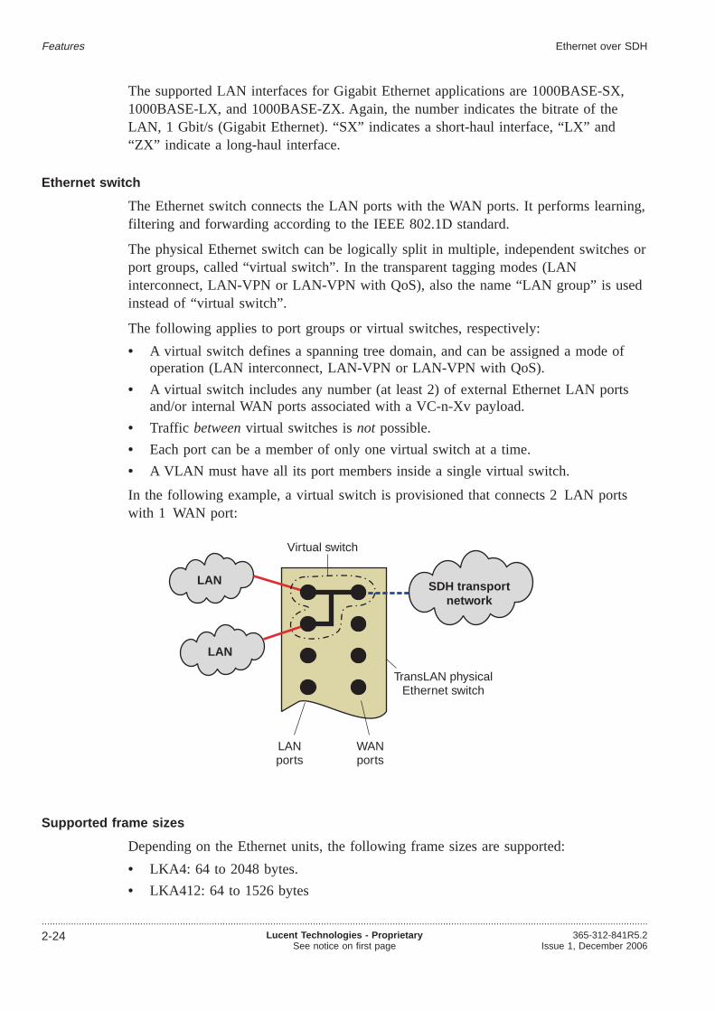
The supported LAN interfaces for Gigabit Ethernet applications are 1000BASE-SX,1000BASE-LX, and 1000BASE-ZX. Again, the number indicates the bitrate of theLAN, 1 Gbit/s (Gigabit Ethernet). “SX” indicates a short-haul interface, “LX” and“ZX” indicate a long-haul interface.
Ethernet switch
The Ethernet switch connects the LAN ports with the WAN ports. It performs learning,filtering and forwarding according to the IEEE 802.1D standard.
The physical Ethernet switch can be logically split in multiple, independent switches orport groups, called “virtual switch”. In the transparent tagging modes (LANinterconnect, LAN-VPN or LAN-VPN with QoS), also the name “LAN group” is usedinstead of “virtual switch”.
The following applies to port groups or virtual switches, respectively:
• A virtual switch defines a spanning tree domain, and can be assigned a mode ofoperation (LAN interconnect, LAN-VPN or LAN-VPN with QoS).
• A virtual switch includes any number (at least 2) of external Ethernet LAN portsand/or internal WAN ports associated with a VC-n-Xv payload.
• Traffic betweenvirtual switches isnot possible.
• Each port can be a member of only one virtual switch at a time.
• A VLAN must have all its port members inside a single virtual switch.
In the following example, a virtual switch is provisioned that connects 2 LAN portswith 1 WAN port:
Supported frame sizes
Depending on the Ethernet units, the following frame sizes are supported:
• LKA4: 64 to 2048 bytes.
• LKA412: 64 to 1526 bytes
LAN
LAN
SDH transportnetwork
Virtual switch
LANports
WANports
TransLAN physicalEthernet switch
Features Ethernet over SDH
....................................................................................................................................................................................................................................
2-24 Lucent Technologies - ProprietarySee notice on first page
365-312-841R5.2Issue 1, December 2006

• LKA12: up to 9022 bytes
• LKA53: up to 9216 bytes (“jumbo frames)”
Ethernet encapsulation with GFP
The generic framing procedure (GFP) is used to adapt the asynchronous Ethernetpayload to the synchronous SDH server layer.
A GFP-header (8 octets) is prepended to each Ethernet frame to indicate frame lengthand payload type. Gaps between Ethernet frames are filled with “IDLE” frames (4octets each).
GFP, standardized by the ITU-T in the recommendations G.7041 and Y.1303, is a veryefficient encapsulation protocol because it has a fixed and small overhead per packet.
In earlier versions (prior to the Garnet network release of June 2002) of theTransLAN® equipment, the Ethernet over SDH (EoS) encapsulation and mappingmethod is used for VC-12 and/or VC-3 based designs (10/100BASE-T Ethernet / FastEthernet cards). EoS is a proprietary encapsulation protocol, based on the ANSIT1X1.5/99-268r1 standard, and can be regarded as a precursor of GFP. EoS and GFPare both length-based encapsulation methods. EoS is similar to GFP in terms of framedelineation and mapping (incl. scrambling); differences between the two encapsulationmethods lie in the size and interpretation of the EoS/GFP encapsulation core headers,as well as the length of the Idle frames.
The generic framing procedure, framed mode (GFP-F) compliant to the ITU-T Rec.G.7041 is available on allTransLAN® products since the Garnet Maintenance /Mercury network release of January 2003.
The following GFP encapsulation are possible:
• Mapping of Ethernet MAC frames into Lower Order SDH VC12–Xv
• Mapping of Ethernet MAC frames into Lower Order SDH VC3–Xv
• Mapping of Ethernet MAC frames into Higher Order SDH VC4–Xv.
VC12–Xv GFP encapsulation
The Metropolis® ADM (Universal shelf) supports virtual concatenation of Lower OrderSDH VC-12 as inverse multiplexing technique to size the bandwidth of a singleinternal WAN port for transport of encapsulated Ethernet and Fast Ethernet packetsover the SDH/SONET network. This is noted VC12-Xv, where X = 1...5. Usage is inconformance with ITU-T G.707 Clause 11 (2000 Edition) and G.783 Clause 12.5(2000).
IDLE GFPHEADER Ethernet frame IDLE IDLE GFP
HEADER
GFPHEADER Ethernet frame IDLE IDLEEthernet frame
Features Ethernet over SDH
....................................................................................................................................................................................................................................365-312-841R5.2Issue 1, December 2006
Lucent Technologies - ProprietarySee notice on first page
2-25

This feature implies specific processing of some overhead bytes:
• Source direction: Each individual VC-12 (from the VC12-Xv group) K4-byte (bit1-2 multiframed) will be written to indicate the values of the multiframe indicator(timestamping), as well as the sequence indicator (individual VC-12 position insidea VC12-Xv)
• Sink direction: Each individual VC-12 (from the VC12-Xv group) K4-byte (bit 1-2multiframed) multi-framing indicator and sequence indicator is used to check thatthe differential delay between the individual VC-12s of the VC12-Xv remainswithin implementation limits.
Additionally, the use of G.707 Extended Signal Label is supported using V5(bits 5-7)field, in which the “101” value is written, which points to the appropriate bits ofK4(bit 1) multiframe for writing in the Extended Signal Label value.
VC3–Xv GFP encapsulation
The Metropolis® ADM (Universal shelf) supports virtual concatenation of Lower OrderSDH VC-3 as inverse multiplexing technique to size the bandwidth of a single internalWAN port for transport of encapsulated Ethernet and Fast Ethernet packets over theSDH/SONET network. This is noted VC3–Xv, where X = 1,2 (SDH). Usage is inconformance with ITU-T G.707 Clause 11 (2000 Edition) and G.783 Clause 12.5(2000) and T1X1 T1.105 Clause 7.3.2 (2001 Edition).
This feature implies specific processing of some overhead bytes:
• Source direction; each individual VC-3 (from the VC3–Xv group) H4-byte will bewritten to indicate the values of the two-stage- multiframe indicator (timestamping),as well as the sequence indicator (individual VC-3 position inside a VC3–Xv)
• Sink direction; each individual VC-3 (from the VC3–Xv group) H4-bytetwo-stage-multi-framing indicator and sequence indicator is used to check that thedifferential delay between the individual VC-3 of the VC3–Xv remains withinimplementation limits.
VC4–Xv GFP encapsulation
The Metropolis® ADM (Universal shelf) supports virtual concatenation of HigherOrder SDH VC-4 as inverse multiplexing technique to size the bandwidth of a singleinternal WAN port for transport of encapsulated Gigabit Ethernet packets over theSDH/SONET network. This is noted VC4/STS3c-Xv, where X = 1...4.
Usage is in conformance with ITU-T G.707 Clause 11 (2000 Edition) and G.783Clause 12.5 (2000) and T1X1 T1.105 Clause 7.3.2 (2001 Edition).
This feature implies specific processing of some overhead bytes:
• Source direction; each individual VC-4 (from the VC4–Xv/STS3c-Xv group)H4-byte will be written to indicate the values of the two-stage multiframe indicator(timestamping), as well as the sequence indicator (individual VC-4 position inside aVC4/STS3x-Xv group).
• Sink direction; each individual VC-4 (from the VC4/STS3c-Xv group) H4-bytetwo-stage-multi-framing indicator and sequence indicator is used to check That thedifferential delay between the individual VC-4 of the VC-4/STS3c-Xv remainswithin implementation limits.
Features Ethernet over SDH
....................................................................................................................................................................................................................................
2-26 Lucent Technologies - ProprietarySee notice on first page
365-312-841R5.2Issue 1, December 2006

Virtual concatenation
The virtual concatenation function arranges the Ethernet frames into the right SDHvirtual container. It is possible to map the client’s data signal over a number ofgrouped virtual containers.
Related information
Please refer to“Virtual concatenation” (p. 2-29)for more detailed information.
LAN and WAN ports and VLAN
A VLAN can contain multiple LAN ports and multiple WAN ports.
Multiple LAN ports can be assigned to different VLANs, also mentioned as VirtualLAN’s. This keeps the traffic on each VLAN totally separate. VLAN groups are usedto connect LAN ports and WAN ports. The LAN ports are the physical 10BaseT or100BaseT or 100Base-LX10 or gigabit Ethernet ports on the NE. All valid Ethernetpackets are accepted (both Ethernet 2 and IEEE 802.3). The WAN ports are the logicalconnection points to the SDH channels. The LAN port is the interface between thecustomers Ethernet LAN and the Ethernet switch on the LAN unit. The WAN port isthe internal port between the Ethernet switch and the part of the LAN unit where theEthernet frame is mapped into or de-mapped from SDH payloads.
VLAN trunking
VLAN trunks carry the traffic of multiple VLANs over one single Ethernet link. Theyallow handling of aggregated LAN traffic from multiple end users, via one single highcapacity Ethernet link (Fast Ethernet or Giga Ethernet), to data equipment in a CentralOffice or an IP Edge Router, IP Service Switch or an ATM Switch. The main benefitof VLAN trunking is that TransLAN cards can hand off end user LAN traffic via onehigh capacity LAN port instead of multiple low speed LAN ports.
Advantages of VLAN trunking are:
• it does not require the assignment of customer identifiers (CID tags)
• it permits different 802.1 tagged frames to share the same physical LAN port
• it gives additional flexibility for egress logical WAN port assignment
• it permits successfully routing via an aggregation function.
Features Ethernet over SDH
....................................................................................................................................................................................................................................365-312-841R5.2Issue 1, December 2006
Lucent Technologies - ProprietarySee notice on first page
2-27

Learning bridges
To increases the efficiency of the network, it can be separated into segments. A bridge,which may have several parts, passes packets between multiple network segments. Bynoting at which port an Ethernet packet with a certain source address arrives, thebridge learns to which ports a packet with a certain destination address must be sent. Ifthe port does not know the destination address, then it will send it to all the portsexcept the port where it comes from. The tables which the learning bridge uses to passthe Ethernet packets to its ports are not shown to the user by the management systems.
Example
After the bridge has received a packet from station C it knows that station C isattached to port 2. When the bridge knows to which ports a station is attached, it willsend packets with destination addresses of these stations only to the port the station isattached to (e.g. a packet from station B to station C is only forwarded to port 2).When a destination address of a packet is of a station in its own segment, the packet isnot forwarded by the bridge (e.g. a packet from station D to station E).
Quality of service
Refer to“Quality of Service (QoS) overview” (p. 2-80).
Features Ethernet over SDH
....................................................................................................................................................................................................................................
2-28 Lucent Technologies - ProprietarySee notice on first page
365-312-841R5.2Issue 1, December 2006

Virtual concatenation...................................................................................................................................................................................................................................
The SDH granularity problem
The virtual containers of the SDH have fixed sizes. These virtual containers areimportant for the transport of Ethernet frames over the SDH network:
• VC-12: 2 Mbit/s
• VC-3: 50 Mbit/s
• VC-4: 150 Mbit/s
It is difficult to fit the Ethernet traffic into one of these virtual containers. For manyapplications the containers, or contiguously concatenated virtual containers, such asVC-4-4C (600 Mbit/s) for example, are either too small or too big. This is known asthe granularity problem.
Virtual concatenation is a mechanism by which a number of independent VCs can beused to carry a single payload. This way, the granularity problem is solved.
The following table shows the possible payload sizes, and the virtual containers thatare used for the transport.
Payload Virtual containers Concatenation
2 Mbit/s 1 × VC-12 VC-12
4 Mbit/s 2 × VC-12 VC-12-2v
6 Mbit/s 3 × VC-12 VC-12-3v
8 Mbit/s 4 × VC-12 VC-12-4v
10 Mbit/s 5 × VC-12 VC-12-5v
50 Mbit/s 1 × VC-3 VC-3
100 Mbit/s 2 × VC-3 VC-3-2v
150 Mbit/s 1 × VC-4 VC-4
300 Mbit/s 2 × VC-4 VC-4-2v
450 Mbit/s 3 × VC-4 VC-4-3v
600 Mbit/s 4 × VC-4 VC-4-4v
750 Mbit/s 5 × VC-4 VC-4-5v
900 Mbit/s 6 × VC-4 VC-4-6v
1 Gbit/s 7 × VC-4 VC-4-7v
Virtual concatenation
Virtual concatenation can be used for the transport of payloads that do not fitefficiently into the standard set of virtual containers (VCs).
Virtual concatenation splits the contiguous bandwidth into individual VCs, transportsthese VCs separately over the SDH network, and recombines them to a contiguoussignal at the path termination. An important aspect of virtual concatenation is that it
Features
...................................................................................................................................................................................................................................365-312-841R5.2Issue 1, December 2006
Lucent Technologies - ProprietarySee notice on first page
2-29

only needs to be supported at the end nodes(i.e. at theTransLAN® cards that interfacewith the end-customer’s LAN). The rest of the network simply transports the separatechannels.
Example 1
As an example, the following figure shows the virtual concatenation of 5 × VC-12:
The 10 Mbit/s payload is put into a VC-12–5v, i.e. into a virtual concatenation group(VCG) consisting of 5 virtually concatenated VC-12s. These VC-12s can travel thenetwork independently, and do not have to follow the same route. At the endpoint, theVC-12–5v is reassembled, and the payload is extracted.
Example 2
The second example shows the principle of virtual concatenation in a Gigabit Ethernet(GbE) network application. Protection of the virtually concatenated payload is possiblevia standard SDH transmission protection schemes.
VC-12-5v
10 Mbit/sEthernet payload
VC-12 VC-12 VC-12VC-12VC-12
VC-12 VC-12 VC-12VC-12VC-12
VC-12-5v
10 Mbit/sEthernet payload
0 1 2 3 4
0 1 2 3 4
LAN LANWAN WAN
Network element Network element
Ethernetframe
EthernetframeVC-4-7v VC-4-7v
Features Virtual concatenation
....................................................................................................................................................................................................................................
2-30 Lucent Technologies - ProprietarySee notice on first page
365-312-841R5.2Issue 1, December 2006

Differential delay
Due to the different propagation delay of the VCs a differential delay occurs betweenthe individual VCs. This differential delay has to be compensated and the individualVCs have to be re-aligned for access to the contiguous payload area.
The TransLAN® re-alignment process covers at least a differential delay of 32 ms.
Link Capacity Adjustment Scheme (LCAS)
LCAS is an extension of virtual concatenation that allows dynamic changes in thenumber of channels in a connection. In case channels are added or removed bymanagement actions this will happen without loosing any customer traffic.
LCAS allows a bandwidth service with scalable throughput in normal operation mode.In case of failure the connection will not be dropped completely but only the affectedchannel(s). The remaining channels will continue carrying traffic. LCAS providesautomatic decrease of bandwidth in case of link failure and re-establishment after linkrecovery.
In case only one end supports (or has turned on) the LCAS protocol, the side that doessupport LCAS adapts automatically to the restrictions that are dictated by thenon-supporting end, i.e. the entire link behaves as a link that does not supportin-service bandwidth adaptations.
Dynamic bandwidth adjustment (GbE)
One of the major problems with using Virtual Concatenation is that if one of the VCshas a fault and fails the whole signal fails. This means that if a single VC fails theentire SDH Channel/VCG is lost. The GbE card for theMetropolis® ADM (Universalshelf) network element supports the Link Capacity Adjustment Scheme (LCAS). ThisLCAS allows dynamic bandwidth increase or decrease without loss of signal.Furthermore, if the signal of one or more of the components becomes degraded thenLCAS will autonomously remove those VCs from the group. When the failure isrepaired LCAS will automatically return those component VCs to the SDHChannel/VCG.
The following table indicates the effect LCAS has on the transmission capacity:
Enabling/disablingLCAS
Capacity no VC-nfailures
One or more (but notall) VC-ns failures
All VC-ns fail.
LCAS disabled Working Capacity =Provisioned Capacity
Working Capacity = 0 Working Capacity = 0
LCAS enabled Working Capacity =Provisioned Capacity
Working Capacity isreduced by amount offailed VC-ns servicedegraded.
Working Capacity = 0
Features Virtual concatenation
....................................................................................................................................................................................................................................365-312-841R5.2Issue 1, December 2006
Lucent Technologies - ProprietarySee notice on first page
2-31

With the introduction of LCAS for VC4-Xv an additional attribute “SDHWorkingCa-pacity” is needed. The working capacity shows the value of the actual capacityavailable, this allows the operator to see when service is degraded. The workingcapacity will also be displayed for non-LCAS, showing a zero if the signal is degradedon any VC-n. When LCAS is enabled Working Capacity show a zero only when thesignal is fully degraded. The next three figures depict the effect of LCAS.
Non-degraded service
Non LCAS causing degraded service
With LCAS enabled only signal degradation is caused
Features Virtual concatenation
....................................................................................................................................................................................................................................
2-32 Lucent Technologies - ProprietarySee notice on first page
365-312-841R5.2Issue 1, December 2006

VC allocation (GbE)
There are 4 x VC-4 TTPs on the GbE card. Each of these can be substructured toVC-3 TTPs or used as VC-4 TTPs. When the operator requests an SDH Channel/VCGhe has a choice of various capacities from a single VC-3 (50 Mbit/s) up to VC-4-4v(600 Mbit/s). If the operator requires a bandwidth of say 100 Mbit/s, one of the VC-4TTPs must be adapted into VC-3 TTPs, and two of these will be virtually concatenatedas a VC-3-2v. For the next SDH Channel/VCG the operator will then only have amaximum bandwidth of 450 Mbit/s (VC-4-3v) as this is what is still available.
Features Virtual concatenation
....................................................................................................................................................................................................................................365-312-841R5.2Issue 1, December 2006
Lucent Technologies - ProprietarySee notice on first page
2-33

Spanning tree protocol (STP)...................................................................................................................................................................................................................................
Overview
The spanning tree protocol (STP) is a standard Ethernet method for eliminating loopsand providing alternate routes for service protection. Standard STP depends oninformation sharing among Ethernet switches/bridges to reconfigure the spanning treein the event of a failure. The STP algorithm calculates the best loop-free paththroughout the network.
STP defines a tree that spans all switches in the network; it e.g. uses the capacity ofavailable bandwidth on a link (path cost) to find the optimum tree. It forces redundantlinks into a standby (blocked) state. If a link fails or if a STP path cost changes theSTP algorithm reconfigures the spanning tree topology and may reestablish previouslyblocked links. The STP also determines one switch that will be the root switch; allleaves in the spanning tree extend from the root switch.
Maximum bridge diameter
The maximum bridge diameter is the maximum number of bridges between any twohosts on the bridged LAN for any spanning tree configuration.
For TransLAN® applications the maximum bridge diameter is 25 nodes.
Spanning tree example
The following example network serves to illustrate the principle how a spanning tree isconstructed.
LAN
1a 3a
3b
3c
1c
1b
2c 2b
2a
Switch 1
Switch 2
Switch 3
LAN
LAN
Features
...................................................................................................................................................................................................................................
2-34 Lucent Technologies - ProprietarySee notice on first page
365-312-841R5.2Issue 1, December 2006
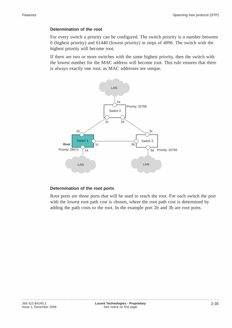
Determination of the root
For every switch a priority can be configured. The switch priority is a number between0 (highest priority) and 61440 (lowest priority) in steps of 4096. The switch with thehighest priority will become root.
If there are two or more switches with the same highest priority, then the switch withthe lowest number for the MAC address will become root. This rule ensures that thereis always exactly one root, as MAC addresses are unique.
Determination of the root ports
Root ports are those ports that will be used to reach the root. For each switch the portwith the lowest root path cost is chosen, where the root path cost is determined byadding the path costs to the root. In the example port 2b and 3b are root ports.
LAN
1a
Root
3a
3b
3c
1c
1b
2c 2b
2a
Switch 1
Switch 2
Switch 3
LAN
LAN
Priority: 28072 Priority: 32768
Priority: 32768
Features Spanning tree protocol (STP)
....................................................................................................................................................................................................................................365-312-841R5.2Issue 1, December 2006
Lucent Technologies - ProprietarySee notice on first page
2-35

For every port a path cost value can be configured. The default path cost parameter ofeach port depends on the bandwidth of the link to which the port is connected.
Determination of the designated and blocked ports
The designated port is the one port that is going to be used for a certain LAN. In theexample, there are 6 LANs.
The designated ports for LAN 1, LAN 2 and LAN 3 are the ports 1a, 2a and 3arespectively, because these LANs have only one connection to a switch. If there aremore connections to a switch, then the port with the lowest root path cost is chosen.Thus the designated ports for LAN 4, LAN 5 and LAN 6 are the ports 1b, 1c and 3crespectively.
LAN
1aPath cost
Path costPath cost
Root
3a
3b
3c
1c
1b
2c 2b
2a
Switch 1
Switch 2
Switch 3
LAN
LAN
r
r
60000
10000
25000
Features Spanning tree protocol (STP)
....................................................................................................................................................................................................................................
2-36 Lucent Technologies - ProprietarySee notice on first page
365-312-841R5.2Issue 1, December 2006

Ports that are neither root ports nor designated ports are blocked. In the example port2c is a blocked port.
Thus the loop free spanning tree is constructed.
Rapid spanning tree protocol (rSTP)
The rapid spanning tree protocol reduces the time that the standard spanning treeprotocol needs to reconfigure after network failures. Instead of several tens of seconds,rSTP can reconfigure in less than a second. The actual reconfiguration time depends onseveral parameters, the two most prominent are the network size and complexity.IEEE802.1w describes the standard implementation for rSTP.
For the special case of multiple cross-connection switches in between the last 60seconds, a filtering function concerning STP notification is implemented. Thisrepetition filter modifies the hold-off time for recalculation of the STP.
Specific attributes forTransLAN® STP enhancements:
• Failure Detection - Use SDH-layer failure detection to trigger STP reconfiguration.
• Convergence Time - Key aspects of the message-based IEEE 802.1w/D10 (rSTP)protocol instead of timer-based 802.1D (STP) protocol.
• Support larger network diameter by adjusting the “Maximum Age Timer” parameterand enhanced STP configuration controls and reports.
• Automatic mode detection - The rSTP is supported as an enhancement to STP, itcannot be enabled explicitly. It rather will operate by default and will fall back toSTP as soon as it finds peer nodes that do not support rSTP. The STP mode thatthe bridge elected can be retrieved per port.
LAN 1
1a
Root
3a
3b
3c
1c
1b
2c 2b
2a
Switch 1
Switch 2
Switch 3
LAN 3
LAN 4 LAN 5
LAN 6
LAN 2
x
r
r
d
d
d
d
d
d
Features Spanning tree protocol (STP)
....................................................................................................................................................................................................................................365-312-841R5.2Issue 1, December 2006
Lucent Technologies - ProprietarySee notice on first page
2-37

GARP VLAN Registration Protocol (GVRP)...................................................................................................................................................................................................................................
Automatic configuration of VLANs
The GARP VLAN Registration Protocol (GVRP) is a protocol that simplifies VLANassignment on network-role ports and ensures consistency among switches in anetwork.
GVRP is supported only in the IEEE 802.1Q / IEEE 802.1ad VLAN tagging modes.In the transparent tagging modes (VPN tagging modes), a similar protocol, theproprietary spanning tree with VPN registration protocol (STVRP) is supported.STVRP is enabled per default and cannot be disabled.
By using GVRP, VLAN identifiers (VLAN IDs) only need to be provisioned oncustomer-role ports of access nodes. VLAN IDs on network-role ports of intermediateand access nodes are automatically configured by means of GVRP. The provisionedVLAN IDs on customer-role ports are called static VLAN entries; the VLANs assignedby GVRP are called dynamic VLAN entries. In addition, GVRP prevents unnecessarybroadcasting of Ethernet frames by forwarding VLAN frames only to those parts of thenetwork that have customer-role ports with that VLAN ID. Thus, the traffic of aVLAN is limited to the STP branches that are actually connecting the VLAN members.
Legend:
1 Static VLAN IDs need to be entered manually at customer-role ports.
2 Dynamic VLAN IDs of intermediate and access nodes areautomatically configured.
3 No automatic configuration of VLAN IDs on ports towards thoseaccess nodes where the respective VLAN ID isnot provisioned, i.e. nounnecessary broadcasting of Ethernet frames by forwarding VLANframes only to those parts of the network that have customer-role portswith that VLAN ID.
A
B C
DE
➀
➀➁
➂
➁LAN
LAN
Features
...................................................................................................................................................................................................................................
2-38 Lucent Technologies - ProprietarySee notice on first page
365-312-841R5.2Issue 1, December 2006

Note that GVRP and the spanning tree protocol (STP) interact with each other. After astable spanning tree is determined (at initialization or after a reconfiguration due to afailure) the GVRP protocol recomputes the best VLAN assignments on all network-roleports, given the new spanning tree topology.
GVRP can be enabled (default setting) or disabled per virtual switch. However, allvirtual switches on an Ethernet network need to be in the same GVRP mode. Forinterworking flexibility one can optionally disable STP per network-role port; implicitlyGVRP is then disabled as well on that port. GVRP must be disabled in order tointerwork with nodes that do not support GVRP.
Max. number of VLANs
The maximum supported number of active VLANs (VLAN identifiers) is limited forreasons of controller performance, and varies depending on product, tagging mode andGVRP activation status. The following table shows the applicable values. Note thateven if the maximum number of active VLANs is limited to 64, 247, or 1024, VLANidentifiers out of the full range of VLAN identifiers (0 4093) can be used for taggingpurposes.
Max. number of active VLANs
Product Transparent tagging (VPNtagging) mode 1
IEEE 802.1Q / IEEE 802.1ad tagging mode
GVRP enabled GVRP disabled
Metropolis® AM /Metropolis® AMS2
64 VLANs per card6 64 VLANs percard
64 VLANs per NE
Metropolis® AMU 64 VLANs per card 247 VLANs percard
1024 VLANs perNE
WaveStar® ADM 16/12 64 VLANs per card 247 VLANs percard
1024 VLANs perNE
Metropolis® ADM (Compactshelf)2
64 VLANs per card 247 VLANs percard
1024 VLANs perNE
Metropolis® ADM (Universalshelf)2
64 VLANs per card 247 VLANs percard
1024 VLANs perNE
LambdaUnite® MSS –3 64 VLANs percard
4093 VLANs perNE
WaveStar® TDM 10G(STM-64)
– 64 VLANs percard
4093 VLANs perNE
Notes:
1. No distinction is made with respect to the STVRP activation status, because STVRP isenabled per default and cannot be disabled.
2. An alarm (MACcVLANOVFW – Maximum number of VLAN instances exceeded) willbe reported when the max. number of active VLANs perTransLAN® card is exceeded.
3. TheLambdaUnite® MSS transparent tagging mode rather compares to the providerbridge tagging mode (see“IEEE 802.1ad VLAN tagging” (p. 2-59)) than to thistransparent tagging (VPN tagging) mode.
Features GARP VLAN Registration Protocol (GVRP)
....................................................................................................................................................................................................................................365-312-841R5.2Issue 1, December 2006
Lucent Technologies - ProprietarySee notice on first page
2-39

A maximum number of 1024 active VLANs per network element is supported.
A maximum of 5000 VLAN/port associations is supported per network element, exceptfor the Metropolis® AM/Metropolis® AMS, where the maximum number ofVLAN/port associations is 2000. An alarm (MIBcVLANOVFW –Maximum number of VLAN instances exceeded in MIB) will be reported when themax. number of VLAN/port associations per network element is exceeded.
Features GARP VLAN Registration Protocol (GVRP)
....................................................................................................................................................................................................................................
2-40 Lucent Technologies - ProprietarySee notice on first page
365-312-841R5.2Issue 1, December 2006

Ethernet over SDH applications...................................................................................................................................................................................................................................
Purpose
This section gives an introduction to the possibleTransLAN® Ethernet over SDHapplications.
Types of applications
Layer-2 switching allows different types of applications, including:
• Ethernet point-to-point transport
• Ethernet point-to-point transport in buffered repeater mode
• Ethernet multipoint transport (dedicated bandwidth)
• Ethernet multipoint transport (shared bandwidth)
• Ethernet multiplexing (VLAN trunking)
TransLAN® supports all Ethernet transport solutions. Specific system configuration isrequired for each network application.
Direct interconnection of two LANs - Ethernet point-to-point transport
The most straight-forward Ethernet application on theTransLAN® equipment is aleased line type of service with dedicated bandwidth to interconnect two LANsegments which are at a distance that cannot be bridged by using a simple Ethernetrepeater, because the collision domain size rules would be violated.
The two interconnected LANs need not be of the same speed; it is possible tointerconnect a 10BASE-T and a 100BASE-T LAN this way for example.
SDH network
LAN
LAN
Ethernet connection
TransLAN equipment
Features
...................................................................................................................................................................................................................................365-312-841R5.2Issue 1, December 2006
Lucent Technologies - ProprietarySee notice on first page
2-41

Mode of operation
Ethernet point-to-point transport can be realized by using any of theTransLAN®
operational modes. However, the preferred mode of operation for the directinterconnection of two LANs is the repeater mode.
Related information
Please also refer to“Repeater mode” (p. 2-49).
Ethernet multipoint transport with dedicated bandwidth
The following figure shows a network example of a multipoint Ethernet over SDHnetwork with dedicated bandwidth:
This multipoint network is dedicated to a single user.
Mode of operation
Ethernet multi-point transport with dedicated bandwidth can be realized by using anyof the following TransLAN® operational modes:
• LAN-VPN mode
• STP virtual switch mode compliant with IEEE 802.1Q
• STP virtual switch mode compliant with IEEE 802.1ad (provider bridge mode)
TransLAN equipment
SDH network
LAN(customer A)
Ethernet connection
LAN(customer A)
LAN(customer A)
LAN(customer A)
Features Ethernet over SDH applications
....................................................................................................................................................................................................................................
2-42 Lucent Technologies - ProprietarySee notice on first page
365-312-841R5.2Issue 1, December 2006
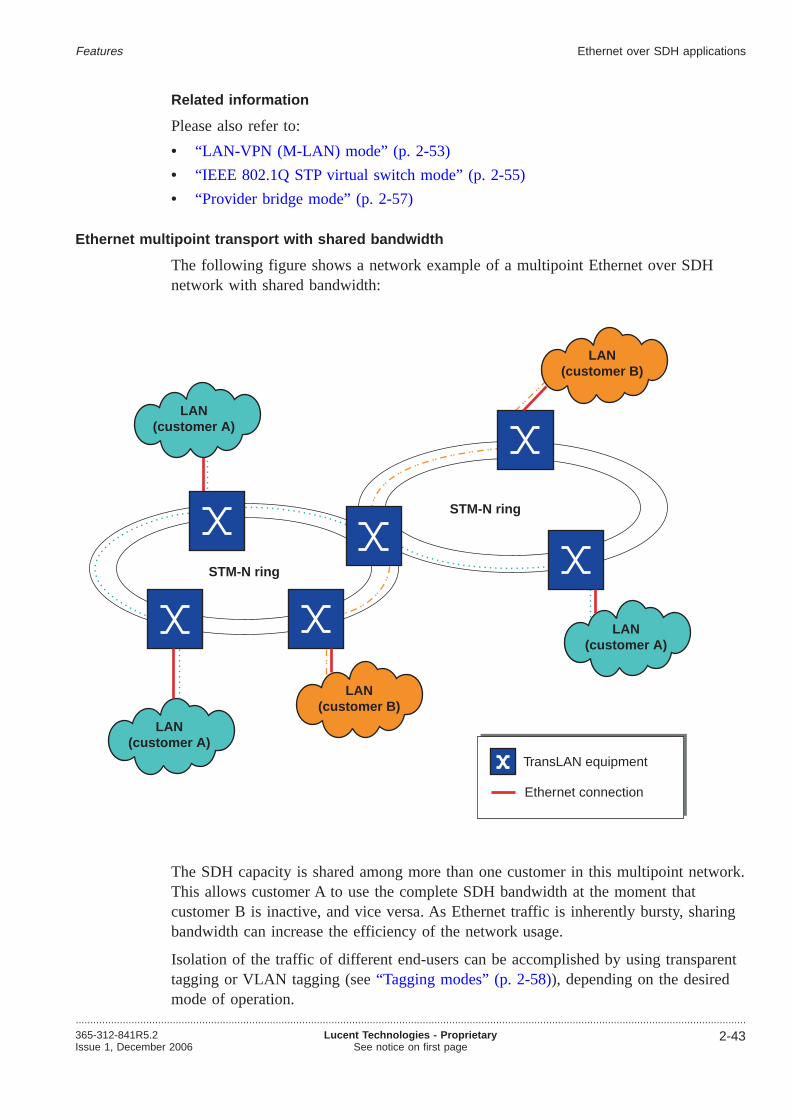
Related information
Please also refer to:
• “LAN-VPN (M-LAN) mode” (p. 2-53)
• “IEEE 802.1Q STP virtual switch mode” (p. 2-55)
• “Provider bridge mode” (p. 2-57)
Ethernet multipoint transport with shared bandwidth
The following figure shows a network example of a multipoint Ethernet over SDHnetwork with shared bandwidth:
The SDH capacity is shared among more than one customer in this multipoint network.This allows customer A to use the complete SDH bandwidth at the moment thatcustomer B is inactive, and vice versa. As Ethernet traffic is inherently bursty, sharingbandwidth can increase the efficiency of the network usage.
Isolation of the traffic of different end-users can be accomplished by using transparenttagging or VLAN tagging (see“Tagging modes” (p. 2-58)), depending on the desiredmode of operation.
TransLAN equipment
STM-N ring
STM-N ring
Ethernet connection
LAN(customer A)
LAN(customer A)
LAN(customer A)
LAN(customer B)
LAN(customer B)
Features Ethernet over SDH applications
....................................................................................................................................................................................................................................365-312-841R5.2Issue 1, December 2006
Lucent Technologies - ProprietarySee notice on first page
2-43

Mode of operation
Ethernet multi-point transport with shared bandwidth can be realized by using any ofthe following TransLAN® operational modes:
• LAN-VPN mode
• STP virtual switch mode compliant with IEEE 802.1Q
• STP virtual switch mode compliant with IEEE 802.1ad (provider bridge mode)
Related information
Please also refer to:
• “LAN-VPN (M-LAN) mode” (p. 2-53)
• “IEEE 802.1Q STP virtual switch mode” (p. 2-55)
• “Provider bridge mode” (p. 2-57)
VLAN trunking
Trunking applications are a special case of Ethernet multipoint transport, either withdedicated or shared bandwidth.
Trunking applications are those applications where traffic of multiple end-users ishanded-off via a single physical Ethernet interface to a router or switch for furtherprocessing. This scenario is also called “back-hauling”, since all traffic is transported toa central location, e.g. a point-of-presence (PoP) of a service provider.
Trunking applications can be classified into two topology types:
• Trunking in the hub-node
• Distributed aggregation in the access network
Common to both topology types is that the Ethernet traffic of multiple LANs isaggregated on one or a few well filled Ethernet interfaces, the trunking LANinterface(s). Thus, the Ethernet traffic of multiple end-users can be made available to aservice provider at a central location via a limited mumber of physical connections.Without VLAN trunking, each end-user would need to be connected to the serviceprovider equipment via his own Ethernet interface.
Trunking applications include the aggregation of Ethernet traffic of a single end-user aswell as the aggregation of Ethernet traffic of multiple different end-users. Isolation ofthe traffic of different end-users can be accomplished by using transparent tagging orVLAN tagging (see“Tagging modes” (p. 2-58)), depending on the desired mode ofoperation.
A typical TransLAN® trunking application would be a configuration where many E/FEaccess nodes are combined with a trunking GbE hub node (cf.“Distributed aggregationin the access network” (p. 2-45)).
Trunking in the hub node
This figure shows an example of VLAN trunking in the hub node:
Features Ethernet over SDH applications
....................................................................................................................................................................................................................................
2-44 Lucent Technologies - ProprietarySee notice on first page
365-312-841R5.2Issue 1, December 2006

Each access node is individually connected to the hub node over a single SDHconnection (or even one SDH connection per LAN port). The trunking LAN interfaceis a network-role LAN port. The VLAN tags in the Ethernet frames are preserved, i.e.made available to the service provider, and can thus be used for further processing.
A high WAN port density is required in the hub-node.
Averaging of the peak traffic loads of each access node (or LAN port) is not used.Each SDH link bandwidth has to be engineered for the corresponding amount of peaktraffic.
Distributed aggregation in the access network
This figure shows an example of distributed aggregation in the access network:
X
SDHnetwork
LAN
LANLAN
LAN
Trunking LAN interface(network-role LAN port)
Hub node
Internet
VLAN, ,17 18 19VLAN
,5 91
VLAN,21 22
VLAN66
VLAN , ,, ,566 91
17 18 1921 22
, ,,
ISP router
Accessnodes
Accessnodes
Features Ethernet over SDH applications
....................................................................................................................................................................................................................................365-312-841R5.2Issue 1, December 2006
Lucent Technologies - ProprietarySee notice on first page
2-45

The SDH bandwidth can be shared by many end-users, which allows to gain from thestatistical effects in the traffic offered by each end-user (“statistical multiplexing”).Thus, the distributed aggregation in the access network configuration is morebandwidth efficient than the trunking in the hub node topology.
Another difference is that in the trunking in the hub-node topology, the hub node hasto support many WAN ports, which is not the case in the distributed aggregation in theaccess network configuration.
A certain bandwidth allocation fairness can be guaranteed by applying ingress ratecontrol in the access nodes. Please note that ingress rate control isnot supported onGbE TransLAN® cards but only on E/FETransLAN® cards.
Mode of operation
Trunking applications can be realized by using any of the followingTransLAN®
operational modes:
• LAN-VPN mode
• STP virtual switch mode compliant with IEEE 802.1Q
• STP virtual switch mode compliant with IEEE 802.1ad (provider bridge mode)
X
SDHnetwork
LAN
LANLAN
LAN
Trunking LAN interface(network-role LAN port)
Internet
VLAN, ,17 18 19VLAN
,5 91
VLAN,21 22
VLAN66
VLAN , ,, ,566 91
17 18 1921 22
, ,,
ISP router
Hub node
Accessnodes
Accessnodes
Features Ethernet over SDH applications
....................................................................................................................................................................................................................................
2-46 Lucent Technologies - ProprietarySee notice on first page
365-312-841R5.2Issue 1, December 2006

Related information
Please also refer to:
• “LAN-VPN (M-LAN) mode” (p. 2-53)
• “IEEE 802.1Q STP virtual switch mode” (p. 2-55)
• “Provider bridge mode” (p. 2-57)
Features Ethernet over SDH applications
....................................................................................................................................................................................................................................365-312-841R5.2Issue 1, December 2006
Lucent Technologies - ProprietarySee notice on first page
2-47

Operational modes...................................................................................................................................................................................................................................
Overview of operational modes
TheseTransLAN® operational modes exist:
• Proprietary VPN modes:
– Multipoint LAN bridging mode (“LAN-VPN mode”, “MLAN mode”)
• Standard compliant IEEE modes:
– STP virtual switch mode compliant with IEEE 802.1Q
– STP virtual switch mode compliant with IEEE 802.1ad (“Provider bridgemode”)
Virtual Switch operation mode
When the transparent tagging mode has been selected on the Ethernet Interface card(LAN unit) level, a different Virtual Switch operational mode must be chosen perVirtual Switch. The Virtual Switch can be configured in the following operation modes:
• Repeater
• LAN-interconnect
• LAN-VPN (MLAN)
When the IEE802.1Q/IEEE 802.1a tagging mode has been selected, the operation modeof the Virtual Switch is always Spanning Tree.
The physical Layer 2 (L2) switch that is present on an Ethernet LAN tributary boardcan be split into several logical or virtual switches. A Virtual Switch is a set ofLAN/WAN ports on a Ethernet LAN tributary board that are used by different VLAN’swhich can share the common WAN bandwidth. Each of the virtual switches canoperate in a specific Virtual Switch mode depending on the VLAN tagging scheme,and each Virtual Switch mode allows specific LAN-WAN port associations asexplained in the following paragraphs.
First the VLAN tagging mode has to be specified on LAN unit level, this can be eitherIEEE 802.1Q/IEEE 802.1aVLAN tagging or VPN tagging. In VPN tagging mode,end-user VLAN tags that optionally may appear in the end user traffic are ignored inthe forwarding process. These VLAN tags are carried transparently through the″TransLAN Network″. In VLAN-tagging mode, the VLAN tags are also carriedtransparently, but the VLAN ID in the VLAN tags is used in the forwarding decision.Therefore customers’ VLAN IDs may not overlap on a physical Ethernet switch, theVLAN IDs must be unique per switch pack. (FEP 1_188_14221)
After having provisioned the tagging mode, per virtual switch a different VirtualSwitch operational mode may be chosen. The Ethernet LAN tributary board supportseither the Repeater mode, LAN-Interconnect, LAN-VPN, and Spanning Tree ProtocolVirtual Switch mode of operation. IEEE 802.1D MAC forwarding and address filtering,multi-point bridging and spanning tree protocol (STP) are supported under all modes ofoperation, except the Repeater mode.
Features
...................................................................................................................................................................................................................................
2-48 Lucent Technologies - ProprietarySee notice on first page
365-312-841R5.2Issue 1, December 2006

The following table gives an overview of the different modes and a list of thecorresponding supported functionality:
VLAN TaggingMode
Virtual Switch Mode Ethertype/TPID QoS_CQS(Quality ofService -ClassificationQueueingScheduling)
Dynamic VLANRegistration Protocol
Spanning TreeImplementation
valid per pack valid perunit
VPN Tagging Repeater N/A N/A N/A No STP
LAN Interconnect(DedicatedBandwidth)
N/A N/A STVRP Multiple STP
LAN-VPN (SharedBandwidth)
N/A N/A
LAN-VPN with QoS N/A enabled
IEEE802.1Q/IEEE802.1adVLAN tagging
Spanning TreeSwitched Network
600 ... FFFF,except for8100
disabled GVRP Single STP
enabled
8100 enabled
Repeater 600 ... FFFF,except for8100
disabled N/A No STP
Interoperability of operational modes
Virtual Switches that are configured in the same operational mode can interwork.Virtual Switches not configured in the same operational mode do not interwork in allcases. If a Virtual Switch is configured in the “Repeater” mode or the “STP Switch”mode, it can only interwork with Virtual Switches that are configured in the samemode.
Interworking between a remote LAN-interconnect virtual switch and a VPN virtualswitch is not prohibited, because the LAN-interconnect mode can be seen as a specialcase of the VPN mode.
Repeater mode
A virtual switch in repeater mode consists of exactlyone LAN portandone WAN portin a fix 1:1 relationship. All Ethernet frames entering the virtual switch at a LAN portare transparently forwarded to the corresponding WAN port and transported over thenetwork. None of the standard IEEE Std 802.1D/Q processes (MAC address learning,MAC frames forwarding and filtering, VLAN classification and filtering) applies.Received frames are relayed to the other port of the virtual switch, irrespective of theirformat or contents.
Features Operational modes
....................................................................................................................................................................................................................................365-312-841R5.2Issue 1, December 2006
Lucent Technologies - ProprietarySee notice on first page
2-49

The WAN port that supports the Repeater mode requires the provisioning of thefollowing parameters:
• WAN port capacity; for the Fast Ethernet card requires manual provisioning at 2, 4,6, 8, 10, 50 or 100 Mbit/s and for the Gigabit Ethernet card requires manualprovisioning at VC-12,VC-12, VC-4–4c, VC-4 and VC-3.
• association of the WAN port to a LAN port
• create cross-connections between VC-X and TU-X (where X=12 or 3).
The following figure shows the network element configured in the Repeater operationmode.
A virtual switch in repeater mode emulates an Ethernet repeater except that it
• breaks-up the collision domains,
• removes the length limitation of CSMA/CD LANs, and
• also works in full-duplex mode.
Synonyms
The TransLAN® repeater mode of operation is often also referred to as “promiscuousmode” or “buffered repeater mode”.
Intended use
The repeater mode is only intended to be used in point-to-point configurations to offera leased-lines type of service. The repeater mode is supported by E/FE as well as GbETransLAN® cards.
SDH network
switch cross-connection
LAN ports
WAN ports
Line port
Features Operational modes
....................................................................................................................................................................................................................................
2-50 Lucent Technologies - ProprietarySee notice on first page
365-312-841R5.2Issue 1, December 2006

Configuration rules and guidelines
Please observe these configuration rules and guidelines:
• The use of the repeater mode is limited to virtual switches consisting of exactlyone customer LAN portandone network WAN port. Only point-to-pointconnections are supported.
• No customer identifier (CID) can be configured.
• It is not possible to provision QoS functions.
• Flow control can be enabled or disabled per LAN port.
• No WAN port configurations are possible.
• When a virtual switch is switched from any of the other operational modes intorepeater mode, then all VLAN and QoS configuration information will be reset.When the virtual switch is switched back again into the previous mode, then theseconfiguration settings willnot become operational again but must be provisionedagain.
The Ethernet packets are carried across the SDH network in a channel. When using theFast Ethernet card, each channel comprises up to 5 VC12 or up to 2 VC3concatenated. These VC12s and VC3s behave in the same way as normal SDH VC12sfrom an E1 port or SDH VC3s from an E3 port. There is some buffering in the NE,but it is still possible to lose packets because the channel bandwidth can be less thanthe Ethernet traffic rate. When using the Gigabit Ethernet card, each channel comprisesVC-12, VC-4–4c, VC-4 or VC-3.
LAN-interconnect mode
The LAN-interconnect mode of operation offers dedicated WAN bandwidth to a singleend-user. Under the LAN-interconnect mode of operation, a Virtual Switch must onlycontain LAN ports with the same CID (Customer ID) to ensure the entire WAN portbandwidth allocated for the group is dedicated to a single end-user. Any combinationof LAN- and WAN-ports is allowed, but with a minimum of two ports to bemeaningful.
The following figure shows the network element configured in the LAN-interconnectoperation mode.
Features Operational modes
....................................................................................................................................................................................................................................365-312-841R5.2Issue 1, December 2006
Lucent Technologies - ProprietarySee notice on first page
2-51

The Ethernet packets are carried across the SDH network in a channel. When using theFast Ethernet card, each channel comprises of up to 5 VC12 or of up to 2 VC3concatenated. These VC12s and VC3s behave in the same way as normal SDH VC12sfrom an E1 port respectively normal SDH VC3s from an E3 port. When using theGigabit Ethernet card, each channel comprises of VC-4 or of VC-3.
LAN
LAN
LAN
LAN
X
X
virtualswitch
cross-connection
LAN ports
WAN ports
Line port
Features Operational modes
....................................................................................................................................................................................................................................
2-52 Lucent Technologies - ProprietarySee notice on first page
365-312-841R5.2Issue 1, December 2006

This operation mode support the following features:
• Learning bridges
• Spanning tree
• Additional SDH bandwidth
• Virtual Switch and
• CID (Customer Identifier).
Special case of the LAN-VPN mode
The LAN interconnect mode of operation is a special case of the LAN-VPN operation.In the LAN interconnect mode a virtual switch may contain LAN and WAN ports of asingle user only.
The TransLAN® cards can support both modes of operation simultaneously as long asthe corresponding virtual switches donot include the same WAN ports.
Configuration rules and guidelines
Please observe these configuration rules and guidelines:
• On LAN ports the CID needs to be provisioned manually.The permitted CID value range is [0 4093]. However, note that only values outof the value range [1 4093] can be used to identify a user while the value “0”cannot. The corresponding LAN port is disabled if the CID is set to “0”.
• In the LAN interconnect mode, the virtual switch is dedicated to a single customer.Therefore, all LAN ports of a virtual switch must have thesamecustomer identifier(CID).
• In the LAN interconnect mode, LAN ports are always customer-role ports, andWAN ports are always network-role ports (see“Port provisioning” (p. 2-75)).
LAN-VPN (M-LAN) mode
Under the LAN-VPN (Virtual Private Network) operation mode, a number of LAN-and WAN ports are grouped together to form one virtual switch. The Virtual Switchcontains LAN ports of multiple end-users sharing the same WAN port(s) bandwidth. Tosafeguard each individual end-user’s data flow and to identify an end-user’s VPN fromthe shared WAN, the Ethernet Interface card assigns a CID to each LAN port within aVirtual Switch. The CID of each end-user (or LAN port) must be unique within ashared WAN port to create a fully independent VPN. The VPN provisioning on theWAN ports on the access and intermediate nodes is done automatically by theproprietary protocol STVRP (Spanning Tree with VPN Registration Protocol) that runswithout operator intervention.
The end-users are assigned bandwidth by the operator. It allows multiple end-users toshare the same SDH WAN bandwidth with each end-user being allocated asub-VC-12-Xv (X= 1, 2, 3, 4, 5) or sub-VC-3-Xv (X=1, 2) rate of bandwidth whenusing the Fast Ethernet card and sub-VC-4-Xv (X=1, 2,...7) or sub-VC-3-Xv (X=1, 2)when using the Gigabit Ethernet card. The combined end-user bandwidth is then
Features Operational modes
....................................................................................................................................................................................................................................365-312-841R5.2Issue 1, December 2006
Lucent Technologies - ProprietarySee notice on first page
2-53

mapped to the SDH time-slots and transported in the SDH network as a single dataload. The minimum rate that can be configured per end-user at a LAN port is 150kbit/s. The operator also specifies a traffic policy for each end-user.
The LAN-VPN operation mode controls the shared bandwidth by making use of thefollowing features:
• Learning bridges
• Spanning tree
• V-LAN (Virtual-LAN)
• CID (Customer Identifier)
• Assigned bandwidth policy (CIR = Committed Information Rate and PIR = PeakInformation Rate)
• Additional SDH bandwidth and SDH WAN bandwidth sharing
• Traffic policy (Strict policing/Oversubscription).
The following figure shows the network element configures in the LAN-VPN operationmode
LAN-VPN with QoS mode
Starting with release 4.0, the LAN-VPN with QoS mode, which was supported inreleases prior to release 4.0, is no longer supported.
The QoS features which were supported by the LAN-VPN with QoS mode in previousreleases are different to the new QoS features supported in theMetropolis® ADM(Universal shelf) release 4.0.
VPN tagging mode
VPN tagging is used to identify user frames in the LAN-VPN mode of operation. VPNtagging is often also referred to as “transparent tagging”.
Features Operational modes
....................................................................................................................................................................................................................................
2-54 Lucent Technologies - ProprietarySee notice on first page
365-312-841R5.2Issue 1, December 2006

VPN tagging is characterized as follows:
• Selecting the VPN tagging mode implies that the port role of the ports is fixed.LAN ports are always customer role ports, and WAN ports are always network roleports (see“Flexible port role assignment” (p. 2-76)).
• VPN tagging is a double tagging mode. This means that a customer identifier (CIDtag) is inserted into each frame at each network ingress LAN port. User frames thatare already tagged become double tagged. The CID tag is removed from the frameat each network egress LAN port.
• Ports forward only those frames that have a CID tag which “belongs” to that port(i.e. which has previously been provisioned on that port).
In the VPN tagging mode, the term “LAN group” is synonymously used to the term“virtual switch”.
Configuration rules and guidelines
Please observe these configuration rules and guidelines:
• Be aware that the port role of the LAN and WAN ports is fixed (see above):
– LAN ports are always customer role ports.
– WAN ports are always network role ports.
• On LAN ports the CID needs to be provisionedmanually.
• The CID provisioned on each LAN port must beuniquewithin a shared WAN tocreate a fully independent VPN.The VPN provisioning on the WAN ports is done automatically by means of theproprietary spanning tree with VPN registration protocol (STVRP).
IEEE 802.1Q STP virtual switch mode
The IEE802.1Q/IEEE 802.1a VLAN tagging scheme can be seen as an extension of theLAN-VPN mode, providing more flexibility in defining the VPN’s and in generalleading to a more efficient use of bandwidth. In IEEE 802.1Q VLAN tagging mode, avirtual switch is formed by a combination of LAN- and WAN ports on a physicalswitch that is used by different VLAN’s which can share the common WANbandwidth. Each port can be part of only one virtual switch, but a certain port may beassociated with more than one VLAN. The ports that are associated with a certainVLAN ID form the VLAN Port Member Set.
On ingress, each packet is filtered on its VLAN ID. If the receiving port is a memberof the VLAN to which a received MAC frame is classified, then the frame isforwarded. The user can provision whether untagged packets are dropped, or taggedwith a PVID (Port VLAN ID), via the acceptable frame type parameter.
Example VLAN trunking
The VLAN trunking example shown in the next figure is one of the possibleapplications in this operation mode.
Features Operational modes
....................................................................................................................................................................................................................................365-312-841R5.2Issue 1, December 2006
Lucent Technologies - ProprietarySee notice on first page
2-55

VLAN IDs assigned to LAN Ports should not overlap in case the operator wants toensure Layer-2 security between those LAN Ports (in many applications, LAN Portsare likely to be dedicated to one customer). It is the responsibility of the operator todefine appropriately non-overlapping VLAN IDs on all the created virtual switches.
Also the provisioned PVID, with which untagged incoming frames are tagged, shouldnot overlap with any VLAN ID on the virtual switch of which the customers’ port ispart (again, this is the responsibility of the operator). Manual provisioning ofintermediate nodes can be cumbersome and difficult. Therefore it is recommended touse the auto-provisioning mode for VLAN ID’s on the intermediate nodes. A protocolnamed GVRP (GARP VLAN Registration Protocol) provides this functionality. GVRPis an application of the Generic Attribute Registration Protocol (GARP) application,which runs on top of the active spanning tree topology.
IEEE 802.1Q defines two kinds of VLAN registration entries in the Bridge FilteringDatabase: static and dynamic entries. In theTransLAN® implementation, static entriesneed to be provisioned on access node LAN ports only. GVRP will take care ofconfiguring dynamic entries on the WAN ports of intermediate and access nodes.
A spanning tree per virtual switch is implemented. If the user wants the traffic to beprotected by the spanning tree protocol and uses the manual-provisioning mode, hemust make sure that the WAN ports in the alternative path also will have thecorresponding VLAN IDs assigned. E.g. in a ring topology, all NE’s in the ring must
VLANs 1 to 20
Customers Access Site
VLANs 1 to 10VLANs11 to 20
VC-N -Xv
to/fromISP Router
ISP Premises/Site
FE or GbE interface
VLAN 1 to 10 = VLAN List of customer A
LAN
WAN
VLANs 1 to 10VLANs11 to 20
Customers Access Site
VLAN 11 to 20 = VLAN List of customer B
VC-N -Xv
VLAN trunking
Customer A's + customer B's traffic
Net
wo
rkEl
emen
t
Net
wo
rkEl
emen
t
Net
wo
rkEl
emen
t
LAN
WAN
WAN
LAN
Features Operational modes
....................................................................................................................................................................................................................................
2-56 Lucent Technologies - ProprietarySee notice on first page
365-312-841R5.2Issue 1, December 2006

be provisioned with this VLAN ID. In automatic mode, the GVRP protocol will takecare of the dynamic VLAN ID provisioning. The user has the possibility to flushdynamic VLAN’s, thus remove dynamic VLAN’s that are no longer used.
Only independent VLAN learning is supported. This means, if a given MAC address islearned in a VLAN, the learned information is used in forwarding decisions taken forthat address only relative to that VLAN.
For the IEEE 802.1Q VLAN tagging mode, the oversubscription mode is not supported(cf. “Quality of Service (QoS) overview” (p. 2-80)).
Configurable spanning tree parameters
Even though the management system is an SDH network element manager, the datanetworking problems still need to be addressed when managing network elementscarrying Ethernet traffic. As such the following parameters are visible/provisionable pervirtual switch.
• bridge address
• bridge priority
• root cost
• root port
• port priority
• bridge priority
Provider bridge mode
The provider bridge mode, a double tagging mode with provisionable TPID(“Ethertype”), is - from a functional point of view - comparable to the LAN-VPN withthe chief difference that the provider bridge mode is compliant to the IEEE 802.1adstandard while the VPN modes are Lucent Technologies proprietary modes, and thatthe provider bridge mode supports Quality of Service features while the LAN-VPNdoes not.
Traffic is forwarded based on the destination MAC address and the outer VLAN tag(S-tag).
As in the IEEE 802.1Q STP virtual switch mode, a virtual switch in the providerbridge mode is a set of LAN/WAN ports on a physical switch that are used bydifferent VLANs which can share the common WAN bandwidth. VLANs in the samevirtual switch are defined by their VLAN port member set. An instance of the spanningtree protocol runs on the WAN ports for each virtual switch.
The LAN ports and WAN ports can be configured to be customer-role or network-roleports (see“Flexible port role assignment” (p. 2-76)).
In the provider bridge mode, the IEEE 802.1ad VLAN tagging mode is used (see“IEEE 802.1ad VLAN tagging” (p. 2-59)).
Features Operational modes
....................................................................................................................................................................................................................................365-312-841R5.2Issue 1, December 2006
Lucent Technologies - ProprietarySee notice on first page
2-57

Tagging modes...................................................................................................................................................................................................................................
Overview
Sharing transport channels between multiple users requires the identification of MACframes. Tagging is the process of attaching an identifier, a “tag”, to a MAC frame inorder to identify the user to which the frame pertains.
These tagging modes are supported:
• Transparenttagging (“VPN tagging”)
• IEEE 802.1Q/IEEE 802.1adVLAN tagging
– VLAN tagging compliant with IEEE 802.1Q-1998 (“IEEE 802.1Q VLANtagging”)
– VLAN tagging compliant with IEEE 802.1ad (“IEEE 802.1ad VLAN tagging”,“Provider bridge tagging mode”)
The different tagging modes are explained later-on in this section.
Important! Note that it isnot possible to use different tagging modes at the sametime on the sameTransLAN® card.
However, within the transparent tagging mode there can be virtual switches in therepeater mode, LAN interconnect mode, or LAN-VPN mode (with or without IEEE802.1p QoS) at the same time on the same physical switch.
Transparent tagging
Transparent tagging (or “VPN tagging”) is a double tagging mode used to identifyend-user frames in the LAN-VPN mode of operation.
Selecting the transparent tagging mode implicitely means that the port role of the portsis fixed. LAN ports are always customer-role ports, and WAN ports are alwaysnetwork-role ports (see“Flexible port role assignment” (p. 2-76)).
To enable bandwidth sharing, a customer identification (CID) is associated with everyLAN port. This CID is inserted into incoming Ethernet frames, in an extra tag. MACaddress filtering and learning is done independently for every CID.
Ethernet frames that are already tagged become double tagged. Already presentend-user VLAN tags remain unused in the transparent tagging mode, i.e. every VLANtag is transmitted transparently through the SDH network.
Outgoing frames are only transmitted on LAN ports which have the respective CIDassociated. The extra tag is removed before the Ethernet frames are forwarded to anexternal LAN.
Note that in the VPN tagging mode the term “LAN group” is synonymously used tothe term “virtual switch”.
Features
...................................................................................................................................................................................................................................
2-58 Lucent Technologies - ProprietarySee notice on first page
365-312-841R5.2Issue 1, December 2006

Configuration rules and guidelines
Please observe these configuration rules and guidelines:
• The port role of the LAN and WAN ports is fixed in the operational modes thatmake use of the VPN tagging mode (see above):
– LAN ports are always customer role ports.
– WAN ports are always network role ports.
• On LAN ports the CID needs to be provisionedmanually.
• The CID provisioned on each LAN port must beuniquewithin a shared WAN tocreate a fully independent VPN.
The VPN provisioning on the WAN ports is done automatically by means of theproprietary spanning tree with VPN registration protocol (STVRP).
Important! Changing the tagging mode from transparent tagging to IEEE802.1Q/IEEE 802.1ad VLAN tagging or vice versa istraffic affecting! Furthermore,most objects provisioned in one mode will be deleted or reset to default - exceptthe LAN group / virtual switch infrastructure - when switching to the other mode.
IEEE 802.1Q VLAN tagging
IEEE 802.1Q VLAN tagging is used to identify end-user frames in the STP virtualswitch mode compliant with IEEE 802.1Q.
These are the IEEE 802.1Q VLAN tagging rules:
• On end-user LAN interfaces:
– At each network ingress port, untagged user frames are tagged with a defaultidentifier, the port VLAN identifier (PVID) which is removed from the frame atthe network egress port.Already tagged frames are forwarded if their VLAN identifier is in the port’sstatic or dynamic list of VLAN IDs, i.e. if the port belongs to the configuredport member set for that VLAN ID. The static VLAN ID list is configurable.The dynamic VLAN ID list is automatically generated by making use of theGARP VLAN Registration Protocol (GVRP).
– At each network egress port, the port VLAN identifier (PVID) is removed frompreviously untagged frames that were tagged with the PVID at the ingress port.VLAN tagged frames are forwarded if the port belongs to the configured portmember set for the respective VLAN ID.
• On trunking LAN interfaces,all tagged frames are forwarded in both directions.Untagged frames are discarded (dropped).
• The end-customer VLAN tag sets have to be disjunct.
IEEE 802.1ad VLAN tagging
The IEEE 802.1ad VLAN tagging mode (“provider bridge tagging mode”) is a doubletagging mode with provisionable Ethertype (TPID), used to identify end-user frames inthe STP virtual switch mode compliant with IEEE 802.1ad (“provider bridge mode”).
Features Tagging modes
....................................................................................................................................................................................................................................365-312-841R5.2Issue 1, December 2006
Lucent Technologies - ProprietarySee notice on first page
2-59

At each customer role port, a provider bridge tag carrying a customer identifier (CID)is inserted into each Ethernet frame in the ingress direction, and removed from theframe in the reverse direction. Frames that are already tagged become double tagged.The IEEE 802.1ad VLAN tagging mechanism is transparent to the end-customer. VPNson transit nodes (no customer LAN port) are automatically instantiated by means of thestandard GVRP protocol which optionally can be disabled.
The value of the Ethertype (TPID) can be flexibly chosen. However, some values arereserved for specific purposes, for example:
• 0x0800 for IP
• 0x0806 for ARP
• 0x8847 for MPLS
• 0x8100 is not selectable because this is the default value for the STP virtual switchmode compliant with IEEE 802.1Q.
The recommended value for the Ethertype in the provider bridge tagging mode is0x9100.
Configuration rules and guidelines
Please observe these configuration rules and guidelines:
• The provider bridge mode can be configured by selecting the IEEE 802.1Q / IEEE802.1ad tagging mode in combination with provisioning an Ethertypein the range0x0601 0xFFFF, but unequal to 0x8100. Provisioning the value 0x8100 for theEthertype results in the selection of the STP virtual switch mode compliant withIEEE 802.1Q.The recommended value for the Ethertype in the provider bridge tagging mode is0x9100. Please also observe the reserved values as given above.
• The customer identification (CID) can be configured in the range [0 4093].
Important! Changing the tagging mode is traffic affecting!
Furthermore, most objects provisioned in one mode will be deleted or reset todefault - except the LAN group / virtual switch infrastructure - when switching to adifferent mode.
Tagged MAC frame
The following figure illustrates the structure of the MAC frame in different taggingmodes as well as the structure of the respective tags.
Features Tagging modes
....................................................................................................................................................................................................................................
2-60 Lucent Technologies - ProprietarySee notice on first page
365-312-841R5.2Issue 1, December 2006

Legend:
TPID Tag protocol identifier (“Ethertype”) - indicates the presence ofa VLAN tag (or CID tag, respectively). Furthermore, itindicates that the lenght/type field can be found at a differentposition in the frame (moved by 4 bytes).
UP (3 bits) User priority - “0” (low priority) “7” (high priority).
CFI (1 bit) Canonical Format Identifier - indicates the presence or absenceof routing information.
Destination address
IEEE 802.1Q VLAN tagging modeVPN tagging mode /
IEEE 802.1ad VLAN tagging mode
Destination address
VLAN tag (C-tag) CID-tag (S-tag)
VLAN tag (C-tag)
TPID
UP CFI VID (V ... V )8 11
Length/Type
Length/Type
Source address Source address
Payload Payload
6 6
6 6
4 4
4
4
4
2
2
46 - 1500
46 - 1500MA
C fr
ame
(64
- 15
22 b
ytes
)
MA
Cfr
ame
(68
-15
26by
tes)
FCS
FCS
2
2VID (V ... V )1 7
TP
ID(e
.g.0
x91
00
)
S-tag
S-V
ID(c
on
t.)
S-V
IDS
-UP
S-CFI
v 11,
v 10,
v 9,
v 8
v 7,
v 6,v
5,v 4
,v3,
v 2,v
1,v 0
p 2,
p 1,
p0
TP
ID
C-tag
(co
nt.
)
C-CFI
v 11,
v 10,
v 9,
v 8
v 7,
v 6,v
5,v 4
,v3,
v 2,v
1,v 0
p 2,
p 1,
p0
C-U
PC
-VID
(0x8
100)
C-V
ID
Features Tagging modes
....................................................................................................................................................................................................................................365-312-841R5.2Issue 1, December 2006
Lucent Technologies - ProprietarySee notice on first page
2-61
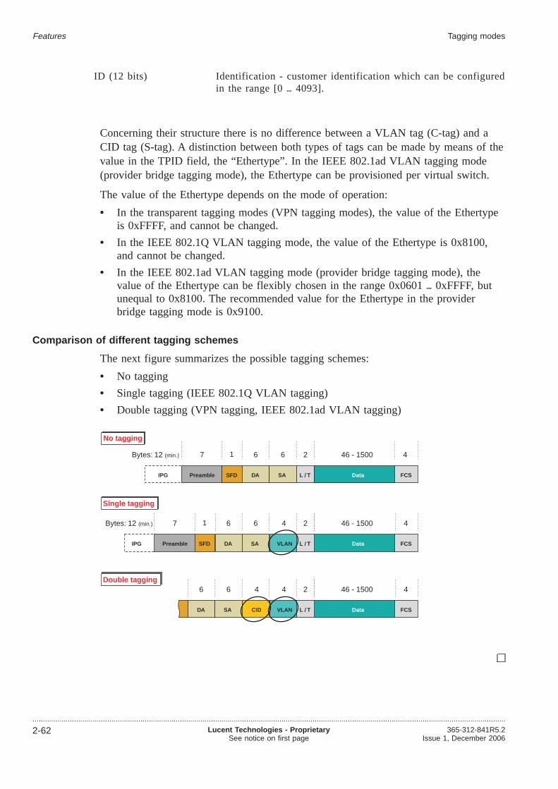
ID (12 bits) Identification - customer identification which can be configuredin the range [0 4093].
Concerning their structure there is no difference between a VLAN tag (C-tag) and aCID tag (S-tag). A distinction between both types of tags can be made by means of thevalue in the TPID field, the “Ethertype”. In the IEEE 802.1ad VLAN tagging mode(provider bridge tagging mode), the Ethertype can be provisioned per virtual switch.
The value of the Ethertype depends on the mode of operation:
• In the transparent tagging modes (VPN tagging modes), the value of the Ethertypeis 0xFFFF, and cannot be changed.
• In the IEEE 802.1Q VLAN tagging mode, the value of the Ethertype is 0x8100,and cannot be changed.
• In the IEEE 802.1ad VLAN tagging mode (provider bridge tagging mode), thevalue of the Ethertype can be flexibly chosen in the range 0x0601 0xFFFF, butunequal to 0x8100. The recommended value for the Ethertype in the providerbridge tagging mode is 0x9100.
Comparison of different tagging schemes
The next figure summarizes the possible tagging schemes:
• No tagging
• Single tagging (IEEE 802.1Q VLAN tagging)
• Double tagging (VPN tagging, IEEE 802.1ad VLAN tagging)
IPG
Bytes: 12 (min.) 7 1 6 6 2 46 - 1500 4
Preamble SFD DA SA L / T Data FCS
IPG
Bytes: 12 (min.) 7 1 6 6 46 - 15004
Preamble SFD DA SA Data FCS
2
L / TVLAN
4
46 - 15004
Data FCS
2
L / TVLAN
44
CID
6 6
DA SA
No tagging
Single tagging
Double tagging
Features Tagging modes
....................................................................................................................................................................................................................................
2-62 Lucent Technologies - ProprietarySee notice on first page
365-312-841R5.2Issue 1, December 2006
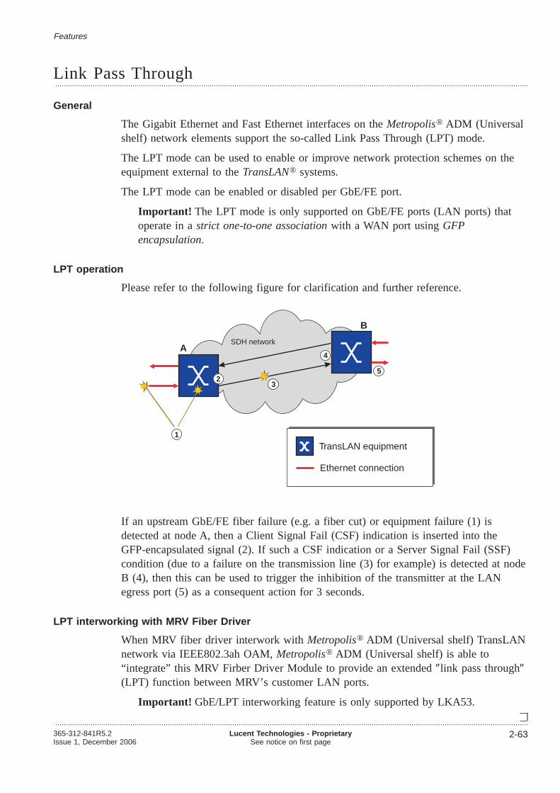
Link Pass Through...................................................................................................................................................................................................................................
General
The Gigabit Ethernet and Fast Ethernet interfaces on theMetropolis® ADM (Universalshelf) network elements support the so-called Link Pass Through (LPT) mode.
The LPT mode can be used to enable or improve network protection schemes on theequipment external to theTransLAN® systems.
The LPT mode can be enabled or disabled per GbE/FE port.
Important! The LPT mode is only supported on GbE/FE ports (LAN ports) thatoperate in astrict one-to-one associationwith a WAN port usingGFPencapsulation.
LPT operation
Please refer to the following figure for clarification and further reference.
If an upstream GbE/FE fiber failure (e.g. a fiber cut) or equipment failure (1) isdetected at node A, then a Client Signal Fail (CSF) indication is inserted into theGFP-encapsulated signal (2). If such a CSF indication or a Server Signal Fail (SSF)condition (due to a failure on the transmission line (3) for example) is detected at nodeB (4), then this can be used to trigger the inhibition of the transmitter at the LANegress port (5) as a consequent action for 3 seconds.
LPT interworking with MRV Fiber Driver
When MRV fiber driver interwork withMetropolis® ADM (Universal shelf) TransLANnetwork via IEEE802.3ah OAM,Metropolis® ADM (Universal shelf) is able to“integrate” this MRV Firber Driver Module to provide an extended″link pass through″(LPT) function between MRV’s customer LAN ports.
Important! GbE/LPT interworking feature is only supported by LKA53.
TransLAN equipment
Ethernet connection
1
4A
B
SDH network
25
3
Features
...................................................................................................................................................................................................................................365-312-841R5.2Issue 1, December 2006
Lucent Technologies - ProprietarySee notice on first page
2-63

Link aggregation...................................................................................................................................................................................................................................
Purpose
Metropolis® ADM (Universal shelf) systems support link aggregation of GigabitEthernet LAN ports in compliance with IEEE 802.3ad.
Link aggregation allows to bundle (“aggregate”) a number of ports with theirtransmission capacity to form a link aggregation group (LAG), which can be treated asif it was a single (logical) link.
Thus, link aggregation can be used toincrease the transmission capacitybytransporting a higher capacity signal over a number of bundled, lower capacity links,and/or toprovide link protection.
Link aggregation for high-density trunking applications
Link aggregation is especially of interest for high-density trunking applications.
Without link aggregation, the second GbE trunking interface between the hub node andthe ISP router would be blocked by the spanning tree protocol (STP) in order to avoidloops.
X
SDHnetwork
LAN
LANLAN
LAN
Aggregated LAN interfacesfor trunking purposes(network-role LAN ports)
Internet
ISP router
Hub node
Accessnodes
Accessnodes
Features
...................................................................................................................................................................................................................................
2-64 Lucent Technologies - ProprietarySee notice on first page
365-312-841R5.2Issue 1, December 2006

Characteristics
Link aggregation inMetropolis® ADM (Universal shelf) systems is characterized asfollows:
• Link aggregation is available for the two GbE ports on the IP-GE/2F-OS (LKA53)Gigabit Ethernet unit only.
• Link aggregation is only possible between two GbE ports that reside on the samecircuit pack.
• Link aggregation provides both link protection and load sharing across theaggregated ports.
Load balancing
The distribution of Ethernet frames across the aggregated ports is important in order toprovide load balancing.
Frame distribution is accomplished as follows:
• If only one of the ports is available for transmission, then all frames to betransmitted will be sent over this port.
• If both ports are available for transmission, then the traffic will be distributedamong the two ports. The distribution algorithm is based on the evaluation of thesource and destination MAC address.
Fault management
There are two alarms related to the aggregation of GbE links:
• The GBE Local Link Agregation partial link loss alarms the situation whereonly one of the two GbE ports is available for transmission.
• The GBE Local Link Agregation total link loss alarms the situation wherethe transmission is completely blocked because none of the two GbE ports isavailable for transmission.
Note that all the fault management functionality related to the individual ports or to thevirtual switch works independently of the LAG.
Configuration settings concerning the Link Pass-Through (LPT) functionality or flowcontrol (pause operation) are automatically applied to both ports of the LAG.
Features Link aggregation
....................................................................................................................................................................................................................................365-312-841R5.2Issue 1, December 2006
Lucent Technologies - ProprietarySee notice on first page
2-65

IGMP snooping...................................................................................................................................................................................................................................
Purpose
Metropolis® ADM (Universal shelf) systems support IGMP snooping.
IGMP snooping can be understood as a generalized MAC address learning mechanismfor multicast MAC addresses. It is based on observing (“snooping”) somenetwork-layer messages exchanged between the multicast routers and the hostsinterested in receiving multicast traffic. IGMP snooping deals only with IPv4 multicasttraffic (which is the prevalent form of multicast in networks nowadays).
IP Group Multicast Protocol IGMP
The Internet Engineering Task Force (IETF) defined IGMP as a means of associatinggroups of IP multicast transmitters and receivers. Each member host of an IP multicastis either a transmitter or a receiver.
It provides
• a protocol for hosts actively joining / leaving multicast groups
• routers/gateways announcing to other routers that there are hosts willing to join /leave particular multicast groups in their networks
• routers/gateways querying / reporting the multicast participation in their particularnetworks ·
A station that wishes to become a receiver sends an IGMP “group join” message tothat group’s transmitter. Each Layer 3 device that forwards an IGMP join messagerecords the group ID and source interface in its multicast forwarding table. When thetransmitter sends IP multicast traffic, the Layer 3 device will then forward the trafficonly to those interfaces from which it has received join messages. Thus, the Layer 3device forwards IP multicast traffic only to those hosts that have requested it.Applications that use IP multicast, such as those involving streaming media,automatically handle IP multicast group membership. Users do not have to manuallysend IGMP messages.
Over time, the IETF has defined three versions of IGMP:
• IGMPv1:IETF Request for Comments 1112 (RFC 1112) defines the original version ofIGMP. RFC 1112 defines the join message that hosts use to join an IP multicastgroup. However, IGMPv1 does not define a method for hosts to leave a multicastgroup. With IGMPv1, routers must use a timer to determine which hosts are stillmembers of the group.
• IGMPv2: RFC 2236 defines “group leave” messages that enable IP multicast-awaredevices to keep current information on group membership.
• IGMPv3: RFC 3376 represents a major revision of IGMP. Instead of theone-transmitter/many-receiver model of IGMP versions 1 and 2, hosts usingIGMPv3 specify lists of transmitters to listen to.
Features
...................................................................................................................................................................................................................................
2-66 Lucent Technologies - ProprietarySee notice on first page
365-312-841R5.2Issue 1, December 2006

IGMP snooping
IGMP snooping, as the name implies, is a method by which Layer 2 devices can“listen in” on IGMP conversations between hosts and routers. When a switch hears agroup join message from a host, it notes which switch interface it heard the messageon, and adds that interface to the group. Similarly, when a Layer 2 switch hears agroup leave message or a response timer expires, the switch will remove that host’sswitch interface from the group.
IP multicast traffic has some special characteristics. Destination IP addresses formulticast traffic fall within the range of 224.0.0.1 through 239.255.255.255 (althoughsome addresses within this range are reserved). Destination Ethernet addresses formulticast traffic begin with 01:00:5E and end with the lower order 23 bits of thedestination IP address.
IGMP snooping enabled VALN ports support the following IGMP interface roles,which are provisionable and retrievable per VLAN port via management system:
• Non-Router: IGMP snooping will consider that only hosts (and no routers) arereachable through this vlan port
• Router: IGMP snooping will consider that multicast routers (and possibly hosts) arereach-able through this vlan port
• Auto (default): IGMP snooping will auto-detect the vlan port role
Multicast group
A multicast group is a group of zero or more hosts that listen to a particular IPmulticast group address.
• Multicast groups are identified by the IP multicast address.
– 224.0.0.0 is a no-group address
– 224.0.0.1 is the permanent group of all multicast IP hosts (including gateways)on the directly connected network
• There is a fixed mapping defined between IP multicast group addresses andlink-layer addresses for many link layers. The link layer multicast address is usedas the link-layer destination address (DA) when sending IP datagrams to an IPmulticast group address.
• One link-layer for which a mapping exists is Ethernet.The mapping of IP multicast group addresses and Ethernet MAC multicast groupaddresses is as follows:
– IP multicast frames all use MAC addresses beginning with: 0x0100.5Exx.xxxx
– xx.xxxx are the last 23-bits of the IGMP multicast group address.
– Note that the (2**28)-1 defined multicast group IP addresses are mapped onto(2**23)-1 Ethernet MAC multicast group addresses. This is a 32-to-1 mapping,not a one-to-one. Practically, this is only relevant when choosing the IPmulticast group addresses within a network based on Ethernet.
• Max. 3.2 K IP multicast groups aresupported per Ethernet unit.
Features IGMP snooping
....................................................................................................................................................................................................................................365-312-841R5.2Issue 1, December 2006
Lucent Technologies - ProprietarySee notice on first page
2-67
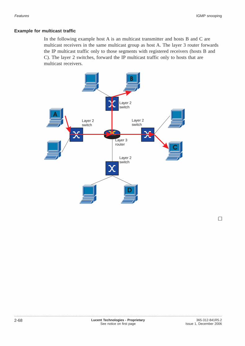
Example for multicast traffic
In the following example host A is an multicast transmitter and hosts B and C aremulticast receivers in the same multicast group as host A. The layer 3 router forwardsthe IP multicast traffic only to those segments with registered receivers (hosts B andC). The layer 2 switches, forward the IP multicast traffic only to hosts that aremulticast receivers.
X
A
B
D
C
Layer 2switch
Layer 2switch
Layer 2switch
Layer 2switch
Layer 3router
Features IGMP snooping
....................................................................................................................................................................................................................................
2-68 Lucent Technologies - ProprietarySee notice on first page
365-312-841R5.2Issue 1, December 2006

IEEE 802.3ah Operations, Administration and Maintenance(OAM)...................................................................................................................................................................................................................................
Introduction
Metropolis® ADM (Universal shelf) systems support Operations, Administration andMaintenance (OAM) functions according to clause 57 of the IEEE 802.3ah-2004standard (included in IEEE 802.3-2005, section 5). OAM provides network operatorsthe ability to monitor the health of the network and quickly determine the location offailing links or fault conditions.
The IEEE 802.3ah OAM mechanism is based on the exchange of information usingframes (802.3ah OAMPDUs) with standardized formats and a standardized protocol(802.3ah OAM protocol).
OAM sublayer
In the IEEE reference model, the IEEE 802.3ah OAM functionality is represented bythe so called OAM sublayer, that is a sublayer between the between the MAC Controlsublayer and the MAC client layers (such as the Link Aggregation (LAG) sublayer, forexample).
Features
...................................................................................................................................................................................................................................365-312-841R5.2Issue 1, December 2006
Lucent Technologies - ProprietarySee notice on first page
2-69
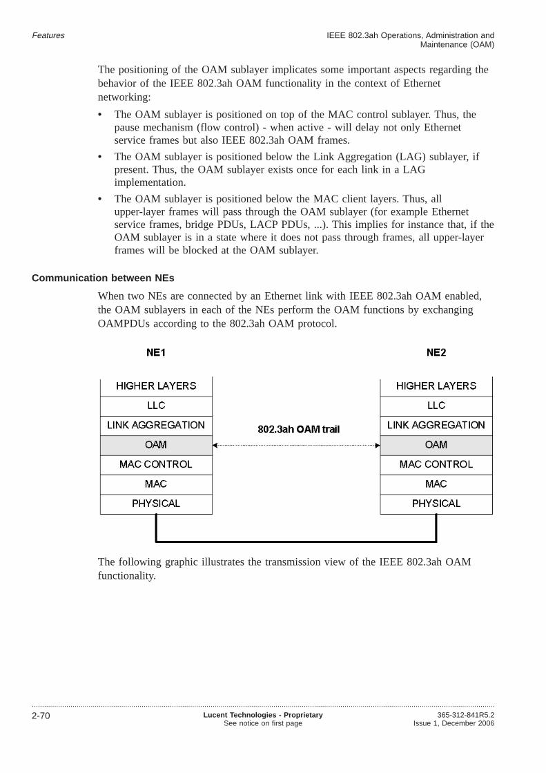
The positioning of the OAM sublayer implicates some important aspects regarding thebehavior of the IEEE 802.3ah OAM functionality in the context of Ethernetnetworking:
• The OAM sublayer is positioned on top of the MAC control sublayer. Thus, thepause mechanism (flow control) - when active - will delay not only Ethernetservice frames but also IEEE 802.3ah OAM frames.
• The OAM sublayer is positioned below the Link Aggregation (LAG) sublayer, ifpresent. Thus, the OAM sublayer exists once for each link in a LAGimplementation.
• The OAM sublayer is positioned below the MAC client layers. Thus, allupper-layer frames will pass through the OAM sublayer (for example Ethernetservice frames, bridge PDUs, LACP PDUs, ...). This implies for instance that, if theOAM sublayer is in a state where it does not pass through frames, all upper-layerframes will be blocked at the OAM sublayer.
Communication between NEs
When two NEs are connected by an Ethernet link with IEEE 802.3ah OAM enabled,the OAM sublayers in each of the NEs perform the OAM functions by exchangingOAMPDUs according to the 802.3ah OAM protocol.
The following graphic illustrates the transmission view of the IEEE 802.3ah OAMfunctionality.
Features IEEE 802.3ah Operations, Administration andMaintenance (OAM)
....................................................................................................................................................................................................................................
2-70 Lucent Technologies - ProprietarySee notice on first page
365-312-841R5.2Issue 1, December 2006
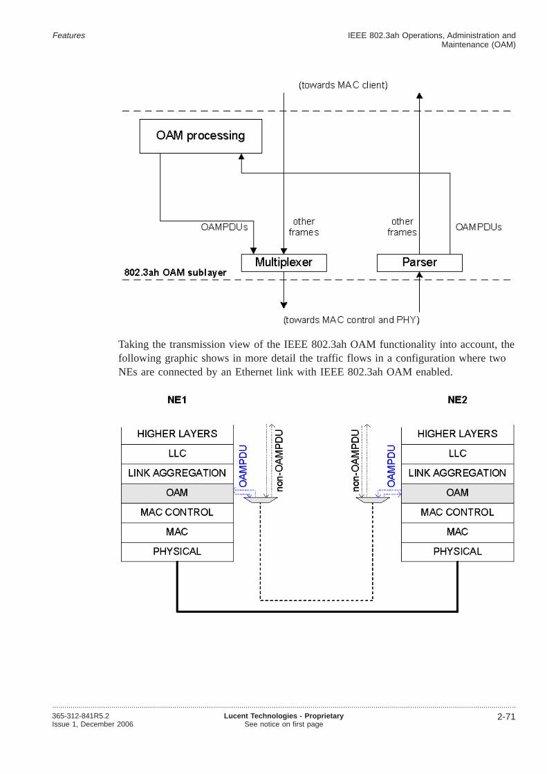
Taking the transmission view of the IEEE 802.3ah OAM functionality into account, thefollowing graphic shows in more detail the traffic flows in a configuration where twoNEs are connected by an Ethernet link with IEEE 802.3ah OAM enabled.
Features IEEE 802.3ah Operations, Administration andMaintenance (OAM)
....................................................................................................................................................................................................................................365-312-841R5.2Issue 1, December 2006
Lucent Technologies - ProprietarySee notice on first page
2-71

IEEE 802.3ah OAM loopbacks
The IEEE standard describes the IEEE 802.3ah OAM loopback as a remotely-controlled facility that can be used for fault localization and link performance testing.The loopback is defined as an OAM-layer loopback, i.e. the affected traffic is loopedat the OAM layer. The following graphic shows the flow of traffic when an 802.3ahOAM loopback is enabled.
IEEE 802.3ah OAM loopbacks are intended to be used to assess the quality of a linkduring network maintenance operations.
Features IEEE 802.3ah Operations, Administration andMaintenance (OAM)
....................................................................................................................................................................................................................................
2-72 Lucent Technologies - ProprietarySee notice on first page
365-312-841R5.2Issue 1, December 2006

IEEE 802.3ah OAM interworking with MRV Fiber Driver...................................................................................................................................................................................................................................
Overview
The MRV Firber Driver Module (refer to“MRV module ” (p. 4-40)) interworks withMetropolis® ADM (Universal shelf) LKA53 TransLAN card via IEEE802.3ah OAM.
The MRV Firber Driver Module helps to:
• Manage ethernet links,
• localize failures cumbersome on unmanaged linksFailures can be seperated
– Operator domain
– Customer location
• Set a demarcation point that allows to expand the operator domain to the customerpremise
The LKA53 together with MRV Firber Driver Module supports the following 802.3ahOAM functions:
• PM for OAM-enabled Ethernet links (based on the errored symbols). Wheninterworking with MRV only near-end PM is available
• Remote loopback enabling/disabling
• MRV LPT interworkingExtended Link Pass Through (LPT) function between MRV’s customer LAN ports.
Configuration example
The following figure gives a example for the interworking ofMetropolis® ADM(Universal shelf) with the MRV Firber Driver Module.
eth 802.3ah
MRV
Transport
Network MADMUMADMU802.3ah
MRVeth User
SwitchethUser
Switcheth
802.3ah link OAM802.3ah link OAM
Features
...................................................................................................................................................................................................................................365-312-841R5.2Issue 1, December 2006
Lucent Technologies - ProprietarySee notice on first page
2-73

Static MAC Address Provisioning...................................................................................................................................................................................................................................
Overview
The switches on theMetropolis® ADM (Universal shelf) data packs operate inself-learning mode, i.e. the source addresses (SA) of received frames are stored in aMAC address table and the destination addresses (DA) of received frames will becompared to those in the table to find the right egress port. Packets whose DA is notfound in the table will be broadcasted to all relevant ports. The dynamic MAC addresstable entries age out after a while (300s) to make room for new entries.
The “Static MAC Address Provisioning” feature allows the user to make manualentries into the MAC address table. These entries will be called static entries and arenot subject to address aging. In case of unicast addresses a single egress port can beprovisioned. In case of multicast addresses (refer to“Multicast group” (p. 2-67)) a listof egress ports can be provisioned.
It is possible to retrieve and remove single dynamic and static MAC address tableentries. This applies to LKA4, LKA12 and LKA53. Note that LKA4 also includesLKA412 and LKA12 also includes LKA12B.
Unlike the other data packs the LKA53 will not automatically share the address tableevenly among all VLANs. So here we can have the situation that the whole table isused up by one VLAN although other VLANs exist. To avoid this the user will be ableto limit the number of dynamically learned addresses per VLAN. This applies toLKA53 only.
Features
...................................................................................................................................................................................................................................
2-74 Lucent Technologies - ProprietarySee notice on first page
365-312-841R5.2Issue 1, December 2006

Port provisioning...................................................................................................................................................................................................................................
Customer-role and network-role ports
The user can assign a so-called “port role” to WAN ports as well as to LAN ports. Inthis way it is possible to forward VLAN tags , especially in double-tagging mode, alsovia LAN ports. Additionally it is possible to run the STP and GVRP protocols onphysical LAN ports, too.
Each LAN port or WAN port can have one of the following port roles:
Customer role Customer-role ports are usually located at the edge of the switchedTransLAN™
network boundary, providing the Ethernet interface to the end-customer.Ethernet frames may be but need not necessarily to be tagged.
In the majority of cases, LAN ports are customer-role ports. However, twoLAN ports connected via an Ethernet LAN link would be an example ofnetwork-role LAN ports. Another example would be a trunking LAN portconnected via an Ethernet LAN link to an ISP router (where VLAN tags areneeded for further processing).
Network role Network-role ports usually interconnect the nodes that make up theTransLAN™ network. Ethernet frames need to be tagged.
In the majority of cases, WAN ports are network-role ports. However, a WANport which is connected to an Ethernet private line unit (EPL unit), thusextending the switchedTransLAN™ network boundary, would be an example ofa customer-role WAN port.
The following figure serves to visualize the concept of customer-role and network-roleports.
EPL unit
Customer LAN port
Network LAN port
Customer WAN port
Network WAN port
“neutral” LAN port
“neutral” WAN port
Ethernet LAN link
SDH link (virtually concatenated VCs)
Switched TransLANnetwork boundary
Features
...................................................................................................................................................................................................................................365-312-841R5.2Issue 1, December 2006
Lucent Technologies - ProprietarySee notice on first page
2-75

Flexible port role assignment
In most cases physical LAN ports have the customer role and physical WAN portshave the network role, but there may be exceptions in some applications. In thefollowing figure the WAN port connects an EPL link and is therefore at the edge of theTransLAN™ network. Thus it has the customer role in this case.
In the example in the figure below the VLAN tags have to be forwarded to a router.The router uses the tagging information for its switch decisions. Additionally the LANport must fulfil a network role. In this case it behaves like a node of theTransLAN™
network. It could also participate in the STP in order to avoid loops, if there wasanother link from a Router LAN interface to a second node within theTransLAN™
network.
A LAN port which operates in the “network role” behaves like a WAN port in terms ofVLAN tagging, STP and GVRP.
The default settings are shown in the following table
Physical ports
Port role LAN port WAN port
Customer role default
Network role default
LAN unit “Ethernet over SDH”
EPL link
LAN
WAN port (“customer role”)
TransLANTM networkLAN unit
LAN unitLAN unit “Ethernet over SDH”
LAN TransLANTM network
LAN port (“network role”)
Router
LAN unitLAN unit
Forbidden acc. to STP
Features Port provisioning
....................................................................................................................................................................................................................................
2-76 Lucent Technologies - ProprietarySee notice on first page
365-312-841R5.2Issue 1, December 2006

In the IEEE 802.1Q STP virtual switch mode and in the provider bridge mode, the portrole of each LAN and WAN port can be flexibly assigned. Each LAN or WAN portcan be configured to be either a customer-role or network-role port.
These are the characteristics of customer-role and network-role ports:
Customer-role port Network-role port
In the IEEE 802.1Q STP virtual switchmode:
In the ingress direction, untagged Ethernetframes are tagged with a default identifier,the port VLAN identifier (PVID). ThePVID is removed from each frame at eachnetwork egress port. See also:“IEEE802.1Q VLAN tagging” (p. 2-59)
In the provider bridge mode:
A provider bridge tag carrying a customeridentifier (CID) is inserted into eachEthernet frame in the ingress direction,and removed from the frame in thereverse direction. Frames that are alreadytagged become double tagged. See also:“IEEE 802.1ad VLAN tagging” (p. 2-59)
No tagging or untagging operations areperformed.
The spanning tree protocol (STP) isnotsupported.
The spanning tree protocol (STP) can beenabled (default setting) or disabled.
GVRP is not supported.
VLAN IDs or CIDs need to be configuredmanually.
GVRP can be enabled (default setting) ordisabled.
Dynamic VLAN IDs or CIDs ofintermediate and access nodes areautomatically configured if GVRP isenabled.
Ingress rate control exists at customer-roleports only (see“Quality of Service (QoS)overview” (p. 2-80)).
There is no rate control on network-roleports.
The traffic class encoded in the p1 and p2bits of the incoming frames is evaluatedand transparently passed through.
Fix port-role assignment in the VPN tagging modes
In all the operational modes relying on the VPN tagging mode (see“Transparenttagging” (p. 2-58)) the port role is fixed:
• LAN ports arealwayscustomer role ports.
• WAN ports arealwaysnetwork role ports.
Features Port provisioning
....................................................................................................................................................................................................................................365-312-841R5.2Issue 1, December 2006
Lucent Technologies - ProprietarySee notice on first page
2-77

This port-role assignment in the VPN tagging modes cannot be changed.Corresponding provisioning options that might be available on the graphical userinterfaces of the management systems do not apply to the VPN tagging modes and areblocked.
Repeater mode
In the repeater mode, there is no necessity to distinguish between customer-role andnetwork-role ports, because the repeater mode can only be used in point-to-pointconfigurations, and there is:
• no tagging mechanism,
• no spanning tree, and
• no GVRP or STVRP.
In the repeater mode, there is simply a LAN port and a WAN port. The LAN portprovides the connection to the end-customer LAN, and the WAN port provides theconnection to the SDH transport network (see“Repeater mode” (p. 2-49)).
Example
As an example, the following figure shows a possible network application:
Legend:
UNI port User-Network-Interface (always a customer-role port)
TransLAN
EPL
Trunk routerTrunk router
Tagging Area
Protocol Area
DiffServ Area
UNI
UNI
UNI
E-NNII-NNI I-NNI
I-NNI I-NNI
I-NNI
Customer-role port
Network-role port
Features Port provisioning
....................................................................................................................................................................................................................................
2-78 Lucent Technologies - ProprietarySee notice on first page
365-312-841R5.2Issue 1, December 2006

I-NNI port Internal Network-Network Interface (always a network-role port)
E-NNI port External Network-Network Interface (here a trunking network-role port)
Features Port provisioning
....................................................................................................................................................................................................................................365-312-841R5.2Issue 1, December 2006
Lucent Technologies - ProprietarySee notice on first page
2-79

Quality of Service (QoS) overview...................................................................................................................................................................................................................................
Introduction
Quality of service (QoS) control allows to differentiate between Ethernet frames withdifferent priorities. If traffic with a high priority and traffic with a low priority competefor SDH capacity, the traffic with the high priority should be served first. This can berealized through quality of service control.
QoS control is supported on the E/FE and Gigabit Ethernet cards, in the IEEE 802.1QVLAN tagging mode and the IEEE 802.1ad VLAN tagging mode (provider bridgemode). QoS control is implemented as a DiffServ architecture applied to layer 2 (inaccordance with IETF recommendations on Differentiated Services, cf. www.ietf.org).
Flow classification, queueing and scheduling
The following figure provides an overview of the QoS control:
Features
...................................................................................................................................................................................................................................
2-80 Lucent Technologies - ProprietarySee notice on first page
365-312-841R5.2Issue 1, December 2006

Quality of Service configuration options
The following table gives on overview of the QoS provisioning options depending onthe configured mode of operation.
Mode of operation Ethertype(hex. value)
QoS CQS QoS_osub Ingress rate control HoL blockingprevention
Repeater mode – [disabled] [disabled] [none] [disabled]
Ingress
Flowclassifier
Flowclassifier
Ratecontroller
Dropper/Marker
Flowclassifier
Network-role ports:
Customer-role ports:
Dropper Queue
Dropper Queue
Dropper Queue
Dropper Queue
SchedulerPrioritymapping
Dropper Queue
Dropper Queue
Dropper Queue
Dropper Queue
SchedulerPrioritymapping
Switch
Egress
Traffic of one flow
Traffic of one traffic class
Traffic at a port
Ratecontroller
Dropper/Marker
Ratecontroller
Dropper/Marker
Ratecontroller
Dropper/Marker
Flowclassifier
Ratecontroller
Dropper/Marker
Ratecontroller
Dropper/Marker
Ratecontroller
Dropper/Marker
Ratecontroller
Dropper/Marker
Features Quality of Service (QoS) overview
....................................................................................................................................................................................................................................365-312-841R5.2Issue 1, December 2006
Lucent Technologies - ProprietarySee notice on first page
2-81

Mode of operation Ethertype(hex. value)
QoS CQS QoS_osub Ingress rate control HoL blockingprevention
VPNmode
LANinterconnect
[0xFFFF] [disabled] [disabled] [none] [disabled]
LAN-VPN [0xFFFF] [disabled] [enabled] strict policing [enabled]
oversubscription
LAN-VPN withQoS
This mode of operation was supported in previous releases. However, it is no longer supportedin the Metropolis® ADM (Universal shelf) release 4.0.
IEEEmode
STP virtualswitch modecompliant withIEEE 802.1Q
0x8100 [enabled] disabled strict policing [enabled]
enabled strict policing,oversubscription
STP virtualswitch modecompliant withIEEE 802.1ad(Provider bridgemode)
0x0601 0xFFFF(≠ 0x8100)
[enabled] enabled strict policing,oversubscription
[enabled]
Notes:
1. QoS CQS: Quality of Service - Classification, Queueing and Scheduling
2. “QoS_osub” represents a configuration parameter which determines if the encoding and evaluation of thedropping precedence is supported (supported if QoS_osub is enabled).
3. Entries in square brackets indicate an implicite selection. If in the “QoS CQS” column for example theentry is “[disabled]”, then the preceding selection of tagging and operation mode implies that Quality ofService - Classification, Queueing and Scheduling (QoS CQS) is not available. It is implicitly disabled,and cannot be enabled.
4. The Ethertype can be set per virtual switch. However, as all virtual switches of aTransLAN™ card areswitched in common, it is effectively set perTransLAN™ card.
5. The distinction between the STP virtual switch mode compliant with IEEE 802.1Q and the STP virtualswitch mode compliant with IEEE 802.1ad (provider bridge mode) can be realized by provisioning theEthertype. In the STP virtual switch mode compliant with IEEE 802.1Q, the Ethertype is fix preset to0x8100. In the provider bridge mode, the Ethertype can be provisioned in the range 0x0600 0xFFFF,but unequal to 0x8100.
6. If “HoL blocking prevention” is enabled then frames that are destined for an uncongested port will not bediscarded as a result of head-of-line blocking.
Ingress rate control provisioning method
If Quality of Service - Classification, Queueing and Scheduling (QoS CQS) is enabled,then ingress rate control can be provisioned per flow by using QoS profiles (see“Quality of Service provisioning” (p. 2-93)). Otherwise, ingress rate control can onlybe provisioned per port.
Features Quality of Service (QoS) overview
....................................................................................................................................................................................................................................
2-82 Lucent Technologies - ProprietarySee notice on first page
365-312-841R5.2Issue 1, December 2006
Service level agreements
On theMetropolis® ADM (Universal shelf) the responsibility for admission control isleft to the operator. This means there is no check that the Service Level Agreements onalready existing connections can be fulfilled, when a new user starts sending data fromnode A to B.
In this respect the notion of over-subscription factor is important. This is the factor bywhich the calculated bandwidth, based on e.g. the traffic matrices of the operatorssharing a link, exceeds the physically available bandwidth. Although theoretically thebandwidth can only be guaranteed for an over-subscription factor≤ 1, in practice anover-subscription factor of 5-10 can be used without giving problems. Due to theeffects of statistical multiplexing it is safe to “sell the bandwidth more than once”. Theburstiness of the traffic from individual customers that share a common link makes thispossible. The Service Level Agreements give a quantification for the “statistics” of themultiplexing.
Provisioning LAN and WAN ports details
The provisioning of the classifier and rate controller per flow is done only on theingress customer-role port (LAN port). On the network ports (WAN port), only thescheduler for the egress queues is provisionable.
It is important that some of the QoS settings are provisioned consistently on all portsthroughout the whole customer’s VPN domain. In the LAN-VPN (M-LAN) operationmode, the rate controller mode (none, strict policing, oversubscription) must beprovisioned consistently (per virtual switch). The latter applies to the only. For thescheduler, for each egress queue the mode = strict_priority/weighted_bandwidth andcorresponding weights (per virtual switch) must be provisioned consistently. This isensured by a background aging function of the system. The parameter will be enforcedto be set equally.
Features Quality of Service (QoS) overview
....................................................................................................................................................................................................................................365-312-841R5.2Issue 1, December 2006
Lucent Technologies - ProprietarySee notice on first page
2-83

Classification, queueing and scheduling...................................................................................................................................................................................................................................
Flow classification
The flow classifier determines into which flow each incoming packet is mapped. Oncustomer-role ingress ports, a number of flows can be defined, based on port, userpriority, VLAN ID, IP-ToS field and Destination MAC ADdress. For each flow a ratecontroller can be specified (CIR/PIR value).
Apart from these flows based on input criteria, a default flow is defined for packetsthat do not fulfil any of the specified criteria for the flows, e.g. untagged packets thathave no user priority field. Thus, untagged traffic is classified per port. All traffic on acertain port is treated equally and attached a configurable default port user priorityvalue to map the traffic on the appropriate queues.
A default user priority can be specified on port level to be added to each packet in thedefault flow (see“Default user priority” (p. 2-88)). Furthermore, the rate controllerbehaviour for the default flow can be specified. The same fixed mapping table fromuser priority to traffic class to egress queue is applied to packets in the default flow asto packets in the specified flows.
Provided that Quality of Service - Classification, Queueing and Scheduling (QoS CQS,cf. “Quality of Service configuration options” (p. 2-81)) is enabled, each flow can beassigned a traffic class by using QoS profiles (see“Quality of Service provisioning”(p. 2-93)).
Each traffic class is associated with a certain egress queue (see“Traffic class to queueassignment” (p. 2-90)).
Ingress direction for network-role ports
For network-role ports, two cases need to be differentiated:
• On I-NNI ports, explicit provisioning of the flow identification (flow configuration)is not provisionable. I-NNI ports always have the default QoS profile assigned. Onan I-NNI port, the only purpose of the flow classifier is to evaluate the traffic class.The traffic class determines the egress queue.
• E-NNI trunk portsmay be split in so-called virtual ports which can be provisionedby means of virtual port descriptors (VPDs). Explicit provisioning of the flowidentification (flow configuration) enables the DiffServEdge function for thisfraction of the network-role port. Ingress rate control of these virtual ports is thesame as for customer-role ports.
Ingress rate control
A rate controller is a means to limit the users access to the network, in case theavailable bandwidth is too small to handle all offered ingress packets.
Rate control is supported for every ingress flow on every DiffServEdge port. There isone rate controller per flow.
Features
...................................................................................................................................................................................................................................
2-84 Lucent Technologies - ProprietarySee notice on first page
365-312-841R5.2Issue 1, December 2006

The actual ingressing data rate is permanently measured and compaired against twoprovisionable data rates, the committed information rate (CIR), and the peakinformation rate (PIR).
On the LKA4 E/FETransLAN® and the LKA12(B) GbETransLAN® units, a singlerate two color marker acc. to IETF RFC2697 is supported.
On the LKA53 GbETransLAN® unit, a two-rate three-color marker acc. to IETFRFC2698 is supported.
Please note that the Token Bucket rate controller as proposed by the standards maylead to the effect that longer frames will more likely be dropped. Consider a signalcontaining two flows, consisting of frames with fixed frame lengths, that areinterleaved with a frequency ratio invers to their frame lengths. If this signal is fed to arate controller, then one frame length will more likely to be dropped than the other.This is not a wrong behavior. However, please note that the effect is a typical testingissue. In reality this will not happen, because usually many different frame lengths arereceived.
The colors are used to specify the dropping precedence. The two rates are used asdelimiter between the colors.
The three colors indicate:
• Green:Low dropping precedence.
• Yellow: Higher dropping precedence.
• Red:The packet will be dropped.
The two rates mean:
Committed Information Rate(CIR)
If the ingressing data rate is less than the committed informationrate, all frames will be admitted to the egress queues. These frameswill be marked “green”, and have a low probability to be dropped atthe egress queues.
The committed information rate is the delimiter between green andyellow packets.
Peak Information Rate (PIR) The peak information rate is the delimiter between yellow and redpackets.
If the ingressing data rate is greater than the committed informationrate (CIR), but less than the peak information rate (PIR), the frameswill be admitted to the egress queues. They will be marked “yellow”and have an increased probability to be dropped.
If the information rate is greater than the PIR, the frames will bemarked “red” and dropped immediately.
Features Classification, queueing and scheduling
....................................................................................................................................................................................................................................365-312-841R5.2Issue 1, December 2006
Lucent Technologies - ProprietarySee notice on first page
2-85
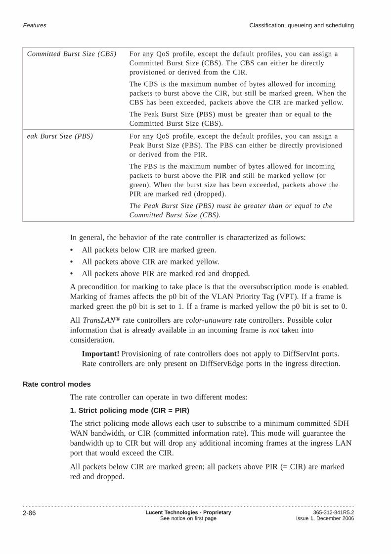
Committed Burst Size (CBS) For any QoS profile, except the default profiles, you can assign aCommitted Burst Size (CBS). The CBS can either be directlyprovisioned or derived from the CIR.
The CBS is the maximum number of bytes allowed for incomingpackets to burst above the CIR, but still be marked green. When theCBS has been exceeded, packets above the CIR are marked yellow.
The Peak Burst Size (PBS) must be greater than or equal to theCommitted Burst Size (CBS).
eak Burst Size (PBS) For any QoS profile, except the default profiles, you can assign aPeak Burst Size (PBS). The PBS can either be directly provisionedor derived from the PIR.
The PBS is the maximum number of bytes allowed for incomingpackets to burst above the PIR and still be marked yellow (orgreen). When the burst size has been exceeded, packets above thePIR are marked red (dropped).
The Peak Burst Size (PBS) must be greater than or equal to theCommitted Burst Size (CBS).
In general, the behavior of the rate controller is characterized as follows:
• All packets below CIR are marked green.
• All packets above CIR are marked yellow.
• All packets above PIR are marked red and dropped.
A precondition for marking to take place is that the oversubscription mode is enabled.Marking of frames affects the p0 bit of the VLAN Priority Tag (VPT). If a frame ismarked green the p0 bit is set to 1. If a frame is marked yellow the p0 bit is set to 0.
All TransLAN® rate controllers arecolor-unawarerate controllers. Possible colorinformation that is already available in an incoming frame isnot taken intoconsideration.
Important! Provisioning of rate controllers does not apply to DiffServInt ports.Rate controllers are only present on DiffServEdge ports in the ingress direction.
Rate control modes
The rate controller can operate in two different modes:
1. Strict policing mode (CIR = PIR)
The strict policing mode allows each user to subscribe to a minimum committed SDHWAN bandwidth, or CIR (committed information rate). This mode will guarantee thebandwidth up to CIR but will drop any additional incoming frames at the ingress LANport that would exceed the CIR.
All packets below CIR are marked green; all packets above PIR (= CIR) are markedred and dropped.
Features Classification, queueing and scheduling
....................................................................................................................................................................................................................................
2-86 Lucent Technologies - ProprietarySee notice on first page
365-312-841R5.2Issue 1, December 2006
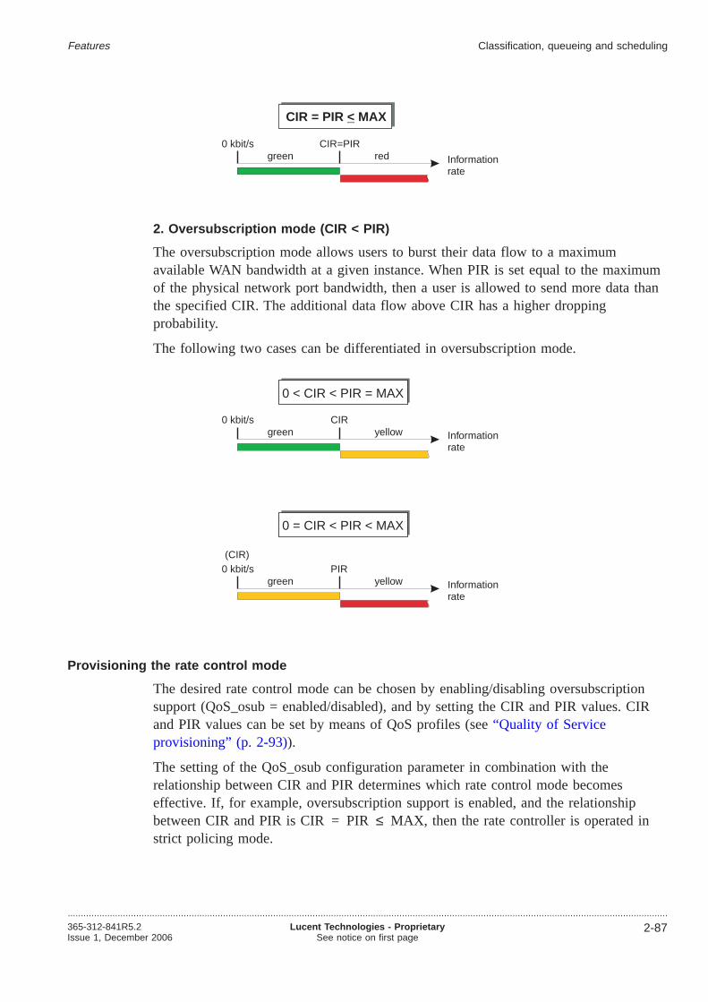
2. Oversubscription mode (CIR < PIR)
The oversubscription mode allows users to burst their data flow to a maximumavailable WAN bandwidth at a given instance. When PIR is set equal to the maximumof the physical network port bandwidth, then a user is allowed to send more data thanthe specified CIR. The additional data flow above CIR has a higher droppingprobability.
The following two cases can be differentiated in oversubscription mode.
Provisioning the rate control mode
The desired rate control mode can be chosen by enabling/disabling oversubscriptionsupport (QoS_osub = enabled/disabled), and by setting the CIR and PIR values. CIRand PIR values can be set by means of QoS profiles (see“Quality of Serviceprovisioning” (p. 2-93)).
The setting of the QoS_osub configuration parameter in combination with therelationship between CIR and PIR determines which rate control mode becomeseffective. If, for example, oversubscription support is enabled, and the relationshipbetween CIR and PIR is CIR = PIR≤ MAX, then the rate controller is operated instrict policing mode.
Informationrate
0 kbit/s CIR=PIRgreen red
CIR = PIR MAX<
Informationrate
0 kbit/s CIRgreen yellow
0 < CIR < PIR = MAX
Informationrate
0 kbit/s PIRgreen yellow
0 = CIR < PIR < MAX
(CIR)
Features Classification, queueing and scheduling
....................................................................................................................................................................................................................................365-312-841R5.2Issue 1, December 2006
Lucent Technologies - ProprietarySee notice on first page
2-87

Important!
1. Which of the rate control modes can actually be configured depends on themode of operation (see“Quality of Service configuration options” (p. 2-81)).
2. As a general rule it is recommended to use the oversubscription mode forTCP/IP applications, especially in case of meshed or ring network topologieswhere multiple end-users share the available bandwidth.
Dropper / Marker
Based on the indication of the rate controller, and the rate control mode for the flow,the dropper/marker will do the following:
No rate control Oversubscription mode Strict policing mode
Incoming rate < CIR mark “green” mark “green” mark “green”
Incoming rate > CIR mark “green” mark “yellow” drop
In the dropper function a decision is made whether to drop or forward a packet. On aTransLAN™ card a deterministic dropping from tail when the queue is full isimplemented.
The LKA53 supports Random Early Drop (RED), instead of tail drop. The LKA53RED parameters are internally fixed, not provisionable.
Packets that are marked red are always dropped. If WAN Ethernet link congestionoccurs, frames are dropped. Yellow packets are always dropped before any of the greenpackets are dropped. This is the only dependency on queue occupation and packetcolor that is currently present in the dropper function. No provisioning is needed.
Default user priority
A default user priority can be configured for each customer-role port. Possible valuesare 0 (lowest priority) 7 (highest priority) in steps of 1. The default setting is 0.
Provisioning of the default user priority doesnot apply to network-role ports.
The default user priority is treated differently depending on the taggging mode:
• LAN-VPN (M-LAN) modeIncoming frames without a user priority encoding (untagged frames) are treated asif they had the default user priority.
• IEEE 802.1Q VLAN tagging mode and provider bridge modeIncoming frames without a user priority encoding (untagged frames) get a defaultuser priority assigned. This C-UP may be furtheron equal to a user priority givenby one of the provisioned flow descriptors. The subsequent traffic class assignmentfor this flow, however, will overwrite this C-UP bits again.
Features Classification, queueing and scheduling
....................................................................................................................................................................................................................................
2-88 Lucent Technologies - ProprietarySee notice on first page
365-312-841R5.2Issue 1, December 2006

Traffic classes
At each ingress port, the traffic class (TC) for each frame is determined. Atcustomer-role ports, this is done via the flow identification and the related provisionedtraffic class. At network-role ports, the traffic class is directly derived from the p-bitsof the outermost VLAN tag.
Depending on the operation mode, these traffic classes exist:
Provider bridge mode and IEEE802.1Q VLAN tagging modewith encoding of the droppingprecedence
The traffic class is encoded in the user priority bitsusing p2 and p1. Thus, 4 traffic classes are defined:0, 1, 2, 3.
IEEE 802.1Q VLAN taggingmodewithout encoding of thedropping precedence
The traffic class is encoded in the user priority bitsusing p2, p1, and p0. Thus, 8 traffic classes aredefined: 0, 0-, 1, 1-, 2, 2-, 3, 3-. The “n” trafficclasses differ from the “n-” traffic classes in thevalue of the p0 bit.
Notes:
1. The support of dropping precedence encoding and evaluation can be enabled or disabledper virtual switch by means of the QoS_osub configuration parameter (QoS_osub =enabled/disabled). All virtual switches belonging to the sameTransLAN™ network mustbe provisioned equally for their TPID and this QoS_osub configuration parameter.
These tables show the traffic class encoding in the user priority bits:
Traffic class p2 p1
0
1
2
3
1
0
0
0
01
1 1
Traffic class p2 p1
0
1
2
3
1
0
0
0
01
1 1
p0
1
0
0
1
0-
1-
2-
3-
1
0
0
0
01
1 1
1
0
0
1
Features Classification, queueing and scheduling
....................................................................................................................................................................................................................................365-312-841R5.2Issue 1, December 2006
Lucent Technologies - ProprietarySee notice on first page
2-89

For the IEEE 802.1Q VLAN tagging mode with oversubscription support (QoS_osub =enabled) it is recommended not to use the n- classes, otherwise all frames will alwaysbe marked yellow (i.e. they will have a higher dropping precedence; p0 = 0). In theprovider bridge mode, any assignment of an n- class will be recognized as the related nclass (tolerant system behavior for inconsistent provisioning).
Traffic class to queue assignment
The assignment of the traffic classes to the egress queues is as follows:
Transparent tagging IEEE 802.1Q VLAN tagging and IEEE 802.1ad VLANtagging (provider bridge mode)
Traffic class Queue Traffic class Queue
3, and Internaluse
4 Internal use 3
2 3 3 (and 3 -) 4
1 2 2 (and 2-) 2
0 1 1 (and 1-) and 0 (and 0-) 1
Notes:
1. “Internal use” means that the queue is used for network management traffic (spanningtree BPDU’s or GVRP PDU’s, for example).
Queueing
The egress treatment is the same for customer-role and network-role ports.
Every port has four associated egress queues. The queues 1 and 2 are to be used fordelay-insensitive traffic (for instance file transfer); the queues 3 and 4 are to be usedfor delay-sensitive traffic (for instance voice or video).
Please refer to“Traffic class to queue assignment” (p. 2-90)for the assignment of thetraffic classes to the egress queues.
Repeater mode
In the repeater mode, there is no queueing process as described above. All frames gothrough the same queue.
Scheduler
The preceding functional blocks assure that all packets are mapped into one of theegress queues, and that no further packets need to be dropped.
Features Classification, queueing and scheduling
....................................................................................................................................................................................................................................
2-90 Lucent Technologies - ProprietarySee notice on first page
365-312-841R5.2Issue 1, December 2006

The scheduler determines the order, in which packets from the four queues areforwarded. The scheduler on each of the four queues can be in one of two operationalmodes, strict priority or weighted bandwidth. Any combination of queues in either ofthe two modes is allowed. When exactly one queue is in weighted bandwidth mode, itis interpreted as a strict priority queue with the lowest priority.
Provided that Quality of Service - Classification, Queueing and Scheduling (QoS CQS,cf. “Quality of Service configuration options” (p. 2-81)) is enabled, the queuescheduling method can be configured as follows:
Queue scheduling method
Strict priority The packets in strict priority queues are forwarded strictly according to the queueranking. The queue with the highest ranking will be served first. A queue with acertain ranking will only be served when the queues with a higher ranking areempty.
The strict priority queues are always served before the weighted bandwidthqueues.
Weightedbandwidth
The weights of the weighted bandwidth queues will be summed up; each queuegets a portion relative to its weight divided by this summed weight, the so-callednormalized weight. The packets in the weighted bandwidth queues are handled ina Round-Robin order according to their normalized weight.
Each of the two modes has his well-known advantages and drawbacks. Strict priorityqueues will always be served before weighted bandwidth queues. So with strictpriority, starvation of the lower priority queues cannot be excluded. Starvation shouldbe avoided by assuring that upstream policing is configured such that the queue is onlyallowed to occupy some fraction of the output link’s capacity. This can be done bysetting the strict policing rate control mode for the flows that map into this queue, andspecifying an appropriate value for the CIR. The strict priority scheme can be used forlow-latency traffic such as Voice over IP and protocol data such as spanning treeBPDU’s or GVRP PDU’s.
Weighted bandwidth queues are useful to assign a guaranteed bandwidth to each of thequeues. The bandwidth can of course only be guaranteed if concurrent strict priorityqueues are appropriately rate-limited.
Usually the queue with the lowest number also has the lowest ranking order, but theranking order of the strict priority queues can be redefined.
Important! It is recommendednot to change the mode and ranking of the queuewhich is used by protocol packets like spanning tree BPDU’s and GVRP PDU’s(queue 3 or queue 4, respectively; cf.“Traffic class to queue assignment” (p. 2-90)).
Weight
A weight can be assigned to each port’s egress queue in order to define the ranking ofthe queue.
Features Classification, queueing and scheduling
....................................................................................................................................................................................................................................365-312-841R5.2Issue 1, December 2006
Lucent Technologies - ProprietarySee notice on first page
2-91

The weight of a strict priority queue has a significance compared to the weight ofother strict priority queues only.
The weight of a weighted bandwidth queue has a significance compared to the weightof other weighted bandwidth queues only.
The weights of the weighted bandwidth queues are normalized to 100%, whereas thenormalized weights of the strict priority queues indicate just ordering.
Example
The following table shows an example of a scheduler table:
Queue Queue scheduling method Weight Normalized weight
1 Weighted bandwidth 5 50%
2 Strict priority 9 1
3 Weighted bandwidth 5 50%
4 Strict priority 15 2
The strict priority queues are served before the weighted bandwidth queues. The strictpriority queue with the highest weight is served first, queue 4 in this example.
In this example, after serving the strict priority queues 4 and 2, the remainingbandwidth is evenly divided over queues 1 and 3.
Depending on the mode of operation, queue 3 or queue 4 is used for networkmanagement traffic, for instance for the spanning tree protocol (see“Traffic class toqueue assignment” (p. 2-90)). Hindering this traffic can influence Ethernet networkstability.
Default settings
These are the default settings of the queue scheduling method and weight:
Queue Queue scheduling method Weight
1 Strict priority 1
2 Strict priority 2
3 Strict priority 3
4 Strict priority 4
Features Classification, queueing and scheduling
....................................................................................................................................................................................................................................
2-92 Lucent Technologies - ProprietarySee notice on first page
365-312-841R5.2Issue 1, December 2006

Quality of Service provisioning...................................................................................................................................................................................................................................
QoS provisioning concept
A 3-stage provisioning concept is used for QoS provisioning. This concept can easilybe adapted to different provisioning needs in different network applications.
port port
12345
130
LKA4
LKA4......LKA4
LKA53
PROFILE 1
CIR PIR TC .... .... .... ....
4500
PROFILE 2
CIR PIR TC .... .... .... ....
4inf1
PROFILE 250
CIR PIR TC .... .... .... ....
0503
1:n*)
type
-
TC = Traffic Class
P# = ID of assigned QoS profile
ID
67
9 .....
.....
VIDs
Ctag(10-100 ; 0-7)IPTOSctagged(...)
Ctag(4093; allUPs)
flow #
1
2
3
4
5
16
P#
1565444
51
OTHERS
port 70
......
PROFILE 51
CIR PIR TC .... .... .... ....
4 4 T
m:255
5 profiles are reserved forfixed default profiles
2
2 Ctag(MASKxx.xx ; 0)
8
max.16
LKA5370
LKA1210
LKA538
PROFILE 91
CIR PIR TC .... .... .... ....
4 4 C
flow#
1
2
3
4
5
....
P#
1135122
51
port 7
DA(00000........00xxxx)IPTOSnoCtag(101110)IPTOSnoCtag(100xxx)IPTOSnoCtag(01xxxx)IPTOSnoCtag(001xxx)
OTHERS
*) 4 of the physical ports per unit(2 at LKA4) may - if they run in NR -split up into virtual ports.The ’virtual port descriptor’ definescriterias based on the S-VID.
virtual port descriptor
Virtual Port =
S-tag(10-15; allS-UPs) ORS-tag(110-115; allS-UPs) ORS-tag(4093; allS-UPs) ]
physical port # AND [
Ctag(12,22 ; 0)Ctag(12,22 ; 1)Ctag(12,22 ; 2,3)Ctag(12,22 ; 4-7)Ctag(allCVIDs ; 4-7)
flow#
1
2
3
4
5
8
P#
1135222
51
OTHERS
port 1
QoS profilesFlow Identification TablesPort type selection (of a unit) max. 255 per NE
max 2000 perNE
Features
...................................................................................................................................................................................................................................365-312-841R5.2Issue 1, December 2006
Lucent Technologies - ProprietarySee notice on first page
2-93

The basic QoS provisioning concept consists of the following stages:
1. For eachport one or more customized flow identification tables (FIT) can beassigned.An FIT can be assigned either to an entire physical port, or to a fraction of aphysical port, i.e. to a so-called “virtual port”. Only E-NNI trunk ports can be splitinto virtual ports each having an FIT assigned. A virtual port can be defined bymeans of a virtual port descriptor (VPD).In case more than one FIT is assigned, each FIT is related to usually one virtualport. Each FIT may also be related to several virtual ports, provided they areidentified by the same virtual port descriptor (VPD).
2. Theflow identification tablescontain the identification criterias for the flows (forexample the values of the C-VID and/or C-UP). Furthermore, the flowidentification tables contain a reference identifying the assigned QoS profile.Up to 2000 flow identification tables are supported per network element.
3. TheQoS profilescontain the provisioning parameters (CIR, PIR, traffic class).
Using this method of QoS provisioning via QoS profiles can be enabled or disabled ona per-NE basis.
On a per-port basis you can decide to only use default QoS profiles, or to define yourown QoS profiles in order to accomplish flow configuration.
Provisioning defaults
The parameter settings in the default QoS profiles for customer-role and network-roleports are:
Port role CIR PIR TC
Customer-role MAX MAX 0
Network-role MAX MAX T
The traffic class “T” is the so-called “transparent traffic class”. The p-bits of theoutermost tag (S-UP of the S-tag, or UP of the VLAN tag) remain unchanged, i.e. keeptheir value which has been assigned by a data unit anywhere upstream.
Explicit provisioning of the flow identification at network-role ports is only intended inthe case of so called external network-network interfaces (E-NNIs) connecting to thenetwork of other operators, or to trunking routers, respectively.
Features Quality of Service provisioning
....................................................................................................................................................................................................................................
2-94 Lucent Technologies - ProprietarySee notice on first page
365-312-841R5.2Issue 1, December 2006

Performance monitoring...................................................................................................................................................................................................................................
Performance counters
On the VC-12, VC-3 or VC-4 termination points connected to a WAN port, standardSDH performance monitoring can be activated. The same counters that apply forVC-12, VC-3 or VC-4 termination points on any other port also apply to the VC-12,VC-3 or VC-4 termination points on a WAN port.
Apart from this standard SDH performance monitoring, a limited amount of countersthat are dedicated to LAN/WAN ports are defined. Activation of these counters can beestablished by setting:
• the LAN/WAN port mode to monitored
• selecting a LAN port or WAN port as active PM point
• setting the PM point type to LAN or WAN.
The supported counters are:
• CbS (total number of bytes sent)
• CbR (total number of bytes received)
• pDe (total number of errored packets dropped)
Note that CbS and CbR are rather traffic monitoring counters than performancemonitoring counters, as they give insight in the traffic load in all places in the network.pDe is a real performance monitoring counter as it gives an indication about theperformance of the network. Only unidirectional PM is supported for these parameters.See the following figure for the location of the measurements. Note that because of thedifference in units, bytes versus packets, the counters cannot be correlated with eachother. Also the counter for dropped packets considers only packets dropped due toerrors, and does not include packets dropped due to congestion.
Performance counters for aggregated ports
The performance counters related to a link aggregation group (LAG) reflect the countsof the signals transmitted/received over all the aggregated ports of the LAG.
CBS
CBR
PDE
PDE
CBS
CBR
Layer-2switchingfunction
EthernetSDH/SONET
WANLANportport
Features
...................................................................................................................................................................................................................................365-312-841R5.2Issue 1, December 2006
Lucent Technologies - ProprietarySee notice on first page
2-95
Ethernet performance monitoring counters
The Ethernet performance monitoring counters can be categorized according to thedifferent purposes they are serving.
The following types of counters can be distinguished:
• Counters for basic Ethernet performance monitoring
• Service monitoring:
– Counters for Ethernet service flow performance monitoring
• Traffic management:
– High quality traffic counters for Ethernet network load performance monitoring
– Low quality traffic counters for Ethernet network load performance monitoring
– Counters for Ethernet congestion monitoring
• Counters for IEEE 802.3ah OAM performance monitoring
• Counters for Ethernet service route round trip delay measurements
Ethernet PM counters per TransLAN ® card
Ethernet performance monitoringcounter
TransLAN ® card
LKA4 LKA412 LKA12 LKA53
Basic Ethernet performance monitoringcounters
Ethernet service flow performancemonitoring counters
–
Ethernet high quality traffic counters –
Ethernet low quality traffic counters –
Ethernet congestion monitoring counters – – –
IEEE 802.3ah OAM performancemonitoring counters
– – –
Ethernet service route round trip delaymeasurements
–
Binning and reporting
The following bins exist for Ethernet performance monitoring parameters:
• 1 current 15-minutes bin
• 16 history 15-minutes bins
• 1 current 24-hours bin
• 1 history 24-hours bin
Features Performance monitoring
....................................................................................................................................................................................................................................
2-96 Lucent Technologies - ProprietarySee notice on first page
365-312-841R5.2Issue 1, December 2006
Equipment features
Overview...................................................................................................................................................................................................................................
Purpose
This section provides information aboutMetropolis® ADM (Universal shelf) featuresconcerning hardware protection, inventory and failure reports.
Contents
Equipment protection 2-98
Optical interface modules 2-101
Equipment reports 2-102
Features
...................................................................................................................................................................................................................................365-312-841R5.2Issue 1, December 2006
Lucent Technologies - ProprietarySee notice on first page
2-97

Equipment protection...................................................................................................................................................................................................................................
The following equipment protection is available:
• 1:N (N ≤ 4); in addition 4 x E1units can be deployed unprotected
• 1+1 E3/DS3
• 1+1 STM-1e
• 1+1 DS1
• 1+1 on Cross-connect/Timing (core units)
• 1:N (N ≤ 4); in addition 4 x DS1 units can be deployed unprotected
• Power (50% + 50%)
Equipment protection configurations
Tributary Slots TSn (n=1..8) can be used with “electrical” port units in combinationwith Paddle Boards. Core 1 and Core 2 slots are used for protection ofCross-Connect/Timing equipment (Core units). A number of equipment protectionschemes can be applied to these units, as depicted in the figure below. The boxes withdark outlines indicate the possible positions of Worker (W) and Protection (P) units.The 1+1 protection schemes for tributaries are always in adjacent odd/even slotpositions. The 1:N protection scheme provides more flexibility in positioning theworker units. The slot position of the protection unit however, is fixed. Free mixing ofprotection schemes is possible, as illustrated in the example configuration at the bottomof the figure.
Features
...................................................................................................................................................................................................................................
2-98 Lucent Technologies - ProprietarySee notice on first page
365-312-841R5.2Issue 1, December 2006

1:N (N ≤ 4) E1 or 1:N (N ≤ 4) DS1
To one set of up to four worker E1 tributary units (or DS1 tributary units) oneprotection unit can be added. If one of the worker units fails, automatically thisprotection unit takes over. The E1/DS1 equipment protection is possible by assigningan E1/DS1 tributary unit to a slot position designated for this purpose.
Up to 4 worker units can then be added to or deleted from the E1/DS1 protectiongroup. Worker units in the protection group must be in one of the four slots designatedfor this purpose. E1 or DS1 units that are not included in the protection group operateunprotected. The protection switching is revertive.
Manual and forced switch commands, as well as temporary lockout of protection aresupported. A protection switch interrupts the traffic of the protected pack. A workingunit, with its traffic switched to the protection unit, can be pulled or replaced withoutcausing bit errors in the traffic, but as soon as a functioning unit is present again, the(revertive) protection algorithm will perform another switch, which does again interruptthe traffic.
The traffic interruption time is less than 50 ms with manual switch commands and lessthan 50 ms plus the detection time for automatic protection switches triggered by afailure. Note that the system provides a second set of four E1 tributary units that cannot be made part of the 1:N protection group.
1+1 E3/DS3
For each working tributary plug-in unit for E3/DS3 interfaces, one protection unit canbe added. If the working unit fails, automatically the protection circuit pack takes over.The switching operation is non-revertive. Clear, manual and forced switch commandsare supported.
Unprotected operation is possible, whereby the slot space for the protection unit can beused to add an extra unprotected unit. If the 1+1 E3/DS3 unit equipment protectionscheme is chosen, the working and protection units need to be in adjacent slots (4designated odd/even slot pairs). A protection switch interrupts the traffic. The unit thatis not active can be pulled or replaced without causing bit errors in the traffic.
The traffic interruption time is less than 50 ms with manual switch commands and lessthan 50 ms plus the detection time for automatic protection switches triggered by afailure.
1+1 STM1e
For each working tributary plug-in unit for STM-1e interfaces, one protection unit canbe added. If the working unit fails, automatically the protection circuit pack takes over.The switching operation is non-revertive. Clear, manual and forced switch commandsare supported.
Features Equipment protection
....................................................................................................................................................................................................................................365-312-841R5.2Issue 1, December 2006
Lucent Technologies - ProprietarySee notice on first page
2-99

Unprotected operation is possible, whereby the slot space for the protection unit can beused to add an extra unprotected unit. If the 1+1 STM-1e unit equipment protectionscheme is chosen, the working and protection units need to be in adjacent slots (4designated odd/even slot pairs). A protection switch interrupts the traffic. The unit thatis not active can be pulled or replaced without causing bit errors in the traffic.
The traffic interruption time is less than 50 ms with manual switch commands and lessthan 50 ms plus the detection time for automatic protection switches triggered by afailure.
1+1 cross-connect/timing unit
The timing, cross-connect and line-port unit can be duplicated. If two units are presentan automatic protection switch relation between the two is set up. The switching isnon-revertive. Manual operation of protection is supported. Unprotected operation ispossible.
The traffic interruption time is less than 50 ms with manual switch commands and lessthan 50 ms plus the detection time for automatic protection switches triggered by afailure. The unit that is not active can be pulled or replaced without causing bit errorsin the traffic.
Features Equipment protection
....................................................................................................................................................................................................................................
2-100 Lucent Technologies - ProprietarySee notice on first page
365-312-841R5.2Issue 1, December 2006

Optical interface modules...................................................................................................................................................................................................................................
Metropolis® ADM (Universal shelf) supports optical port units consisting of a parentboard which can be equipped with field-replaceable optical interface modules, alsocalled Small Form Factor Pluggable modules (SFPs).
An optical interface module is a replaceable unit with a receiver and transmitterfunction providing the optical port.Metropolis® ADM (Universal shelf) opticalinterface modules are “hot pluggable” (field-replaceable), i.e. the interface modules canbe inserted or removed while the parent board is in operation, without affecting theservice of other interface modules on the same parent board.
Advantages of the optical interface modules
The Metropolis® ADM (Universal shelf) optical interface modules provide excellentpay-as-you-grow opportunities for smaller or start-up applications, as only theup-to-date required number of ports must be purchased. An additional advantage of thisflexible interface are ease of handling and cost reduction when it comes tomaintenance and repair activities.
The number of modules inserted into the parent board can be varied flexibly betweenzero and the maximum number of sockets; the possibly unused sockets can be leftempty.
Small Form Factor Pluggable module (SFPs)
The Metropolis® ADM (Universal shelf) SFPs are marked by the manufacturer, andthey are checked upon insertion, in order to protect from accidental insertion of nonMetropolis® ADM (Universal shelf) specific SFPs. Only for theMetropolis® ADM(Universal shelf) specific SFPs Lucent Technologies can guarantee the full functionalityand warranty.
For further information please refer to the “Equipment provisioning concepts” chapterof the UOG.
Features
...................................................................................................................................................................................................................................365-312-841R5.2Issue 1, December 2006
Lucent Technologies - ProprietarySee notice on first page
2-101
Equipment reports...................................................................................................................................................................................................................................
Equipment inventory
Metropolis® ADM (Universal shelf) automatically maintains an inventory of thefollowing information of each installed circuit pack:
• Serial number
• Equipment Carrier Code or Equipment Catalog Item ECI
• Functional name
• Apparatus code
• Series number
• Functional qualifier
• Software release (of the NE)
You can obtain this information by an inventory request command.
Equipment failure reports
Failure reports are generated for equipment faults and can be forwarded via theITM-CIT interfaces.
Features
...................................................................................................................................................................................................................................
2-102 Lucent Technologies - ProprietarySee notice on first page
365-312-841R5.2Issue 1, December 2006

Synchronization and timing
Overview...................................................................................................................................................................................................................................
Purpose
This section provides information about synchronization features, timing protection andtiming interfaces ofMetropolis® ADM (Universal shelf).
Contents
Timing features 2-104
Timing protection 2-105
Timing interface features 2-106
Features
...................................................................................................................................................................................................................................365-312-841R5.2Issue 1, December 2006
Lucent Technologies - ProprietarySee notice on first page
2-103

Timing features...................................................................................................................................................................................................................................
Synchronization modes
Several synchronization configurations can be used. TheMetropolis® ADM (Universalshelf) can be provisioned for the following timing modes:
• free-running operation
• holdover mode
• locked mode
In locked mode the internal SDH Equipment Clock (SEC) is locked to:
• one of the external sync inputs (2048 kHz or 2048 kbit/s)
• two independent 64 kHz signals (for the japanese market; the japanes marketrequires different station clock interfaces: 64 kHz + 8 kHz (+ 400 Hz) for NE inputand 6312 kHz for NE output. )These two independent 64 kHz signals coming from outside are converted by theso-called MIOR-J unit into two independent 2048 kHz signals.
• one of the 2 Mbit/s tributary signals
• one of the STM-N inputs (line or tributary port).
Handling of a frequency offset
By comparing the frequencies of all assigned references with the frequencies of theinternal oscillator on both timing circuits of the core units, it can be decided in theevent of an excessive frequency difference, whether a reference is off-frequency or theinternal oscillator of one of the timing circuits. If so, the affected unit is declaredfaulty.
Features
...................................................................................................................................................................................................................................
2-104 Lucent Technologies - ProprietarySee notice on first page
365-312-841R5.2Issue 1, December 2006

Timing protection...................................................................................................................................................................................................................................
Protection timing references
The external timing references are non-revertively 1+1 protected. The external timingreferences can also operate in unprotected mode.
Protection of the timing mode
If the primary timing reference fails, the system will automatically switch to theholdover mode. The Synchronization Status Message is supported, which enablestiming reference priority settings and gives information about the quality of the timingsignal.
Features
...................................................................................................................................................................................................................................365-312-841R5.2Issue 1, December 2006
Lucent Technologies - ProprietarySee notice on first page
2-105

Timing interface features...................................................................................................................................................................................................................................
Synchronization Status Message (SSM) signal
A timing marker or synchronization status message signal can be used to transfer thesignal-quality level throughout a network. This will guarantee that all network elementsare always synchronized to the highest-quality clock that is available.
On theMetropolis® ADM (Universal shelf) system the SSM algorithm or the timingmarker is supported according to G.781. The SSM is supported on all STM-Ninterfaces and on the 2 Mbit/s synchronization input and output signals.
2 Mbit/s tributary re-timing
The user can choose whether individual 2 Mbit/s tributary outputs operate in“self-timed” or “re-synchronized” mode. In the (standard) self-timed mode, the phaseof the outgoing signal is a moving average of the phase of the 2 Mbit/s signal becausethe 2 Mbit/s signal is embedded in the VC-12 that is disassembled. In there-synchronized mode the 2 Mbit/s signal is timed by the SDH Equipment Clock(SEC) of the network element; frequency differences between the local clock and the2 Mbit/ssignal embedded in the VC-12 to be disassembled are accommodated by a slipbuffer.
There is also the following option: whenever the traceability of the local clock dropsbelow a certain threshold, the re-timing 2 Mbit/s interfaces automatically switch toself-timing. When this fail condition disappears, these interfaces return to re-timing.These changes do not involve any hits in the traffic.
Features
...................................................................................................................................................................................................................................
2-106 Lucent Technologies - ProprietarySee notice on first page
365-312-841R5.2Issue 1, December 2006
Operations, Administration, Maintenance andProvisioning
Overview...................................................................................................................................................................................................................................
Purpose
The following section provides information about interfaces for Operations,Administration, Maintenance, and Provisioning (OAM&P) activities and the monitoringand diagnostics features ofMetropolis® ADM (Universal shelf).
Contents
Interfaces 2-108
Monitoring and diagnostics features 2-110
Features
...................................................................................................................................................................................................................................365-312-841R5.2Issue 1, December 2006
Lucent Technologies - ProprietarySee notice on first page
2-107

Interfaces...................................................................................................................................................................................................................................
User panel
The maintenance procedures of theMetropolis® ADM (Universal shelf) system arebuilt on two levels of system information and control. The first maintenance tierconsists of the user panel display (LEDs) and push-buttons (all on the front of thesystem controller), and the light-emitting diodes (LEDs) on the circuit pack faceplate.The push-buttons are still accessible when the front cover is closed (EMC boundary).Most typical maintenance tasks can be performed using these buttons without aid ofthe the ITM-Craft Interface Terminal (ITM-CIT) or element manager (OMS).
ITM-CIT
The second maintenance tier employs the Lucent Technologies network managementsystem. Detailed information and system control are obtained by using the ITM-CIT(Craft Interface Terminal), which supports provisioning, maintenance and configurationon a local basis.
ITM-NM and OMS
At network level (customer’s network management center), Lucent Technologies’ITM-NM and the OMS perform all the tasks that are necessary to supervise, operate,control and maintain an SDH network with theMetropolis® ADM (Universal shelf).
Security
Metropolis® ADM (Universal shelf) uses logins, passwords, authentication, and accesslevels to protect against unauthorized access.
Local and remote software downloads
With Metropolis® ADM (Universal shelf) software can be downloaded from theITM-CIT. Software downloading does not affect transmission or operations. Activatingthe newly downloaded software may affect operations but does not affect transmission.
TCP/IP tunneling
The Metropolis® ADM (Universal shelf) is capable of tunneling IP traffic through theOSI DCN network. The tunnel provides a virtual interconnection for IP traffic betweenthe “Ethernet interfaces (LAN)” and/or “end-points of other IP-tunnels (terminating inthe NE)” of two NE’s that support this feature.
Note that a tunnel may forward IP traffic for many destinations, that can either beconnected to the QLAN of the far end tunneling NE, or must be reached throughsubsequent routing towards/through other IP-tunnels and/or towards/through external IProuters.
The LAN interface supports both IP and OSI traffic simultaneously. Tunneling isachieved by encapsulating the IP packets in CLNP (OSI) packets.
Features
...................................................................................................................................................................................................................................
2-108 Lucent Technologies - ProprietarySee notice on first page
365-312-841R5.2Issue 1, December 2006

This feature has no effect on the OSI management of theMetropolis® ADM (Universalshelf) itself, apart from the performance impact of additional IP traffic. This featurerequires the NE to act as an IP router itself. The IP router supports ports to theEthernet Interface (Q-LAN) and to the CLNP (OSI) network (i.e. a number of tunnels).
DCC interfaces
The Metropolis® ADM (Universal shelf) system supports operations via the standard7-layer OSI protocol over Data Communications Channel (DCC). Up to 32 DCCterminations of section DCC (DCCR) and line DCC (DCCM) channels can beconfigured on 155-Mbit/s, 622-Mbit/s, 2.5-Gbit/s, 10-Gbit/s ports. DCC channelprotection switching is supported in conjunction with line MSP protection switching ofthe respective optical port (“slaving”).
Features Interfaces
....................................................................................................................................................................................................................................365-312-841R5.2Issue 1, December 2006
Lucent Technologies - ProprietarySee notice on first page
2-109

Monitoring and diagnostics features...................................................................................................................................................................................................................................
Performance monitoring
Metropolis® ADM (Universal shelf) monitors performance parameters for 24-hour and15-minute intervals on the plesiochronous, synchronous and Ethernet transmissioninterfaces, so monitoring can be full-time for each signal without requiring anyadditional cross-connect capacity. For further information please refer to“Performancemonitoring” (p. 5-24).
Threshold reports
Additional to the common alarm status and normal/abnormal condition reportsMetropolis® ADM (Universal shelf) supports threshold reports (TRs). A TR isgenerated when a performance monitoring parameter threshold is exceeded, that can beset individually by the user for 24-hour and 15-minute intervals. For furtherinformation please refer to“Performance monitoring” (p. 5-24).
Port monitoring modes
Each physical interface can be in one of three different modes: automatic (AUTO),monitored (MON) or non-monitored (NMON). In NMON mode all alarms thatoriginate in the physical section termination function are suppressed, while in the MONmode they are reported. In the AUTO mode alarms are suppressed until an incomingsignal is detected, then the mode of the port switches automatically to MON.
Transmission maintenance signals
Regenerator section, multiplex section, and higher order path maintenance signals aresupported as per ITU-T Rec. G.783. The system can generate and retrieve path tracemessages on STS-1 respectively higher order VC-3 and VC-4 level as well as sectiontrace messages respectively STM-N RSOH messages.
Path termination point monitoring modes
Each Path Termination Point can be in one of two different modes, monitored (MON)or non-monitored (NMON). In NMON mode all alarms that originate in thetermination point are suppressed, while in the MON mode they are reported .
Alarm Severity Assignment Profiles
An Alarm Severity Assignment Profile (ASAP) is a list of alarms which can occur in anetwork element and which each have an alarm severity assigned.
ASAPs can be assigned toMetropolis® ADM (Universal shelf) functional systemcomponents (a circuit pack or a specific port for example) during provisioning.
Each ASAP can be uniquely identified by its type and its name.
Features
...................................................................................................................................................................................................................................
2-110 Lucent Technologies - ProprietarySee notice on first page
365-312-841R5.2Issue 1, December 2006

ASAPs allow the user to control alarm reporting with more flexibility, and to createmultiple alarm profiles for each alarm category and to assign these profiles to entitieswithin the system.
All alarms are grouped into types of alarms. The alarms contained in each category arepredefined. The categories containing the alarms are referred to as predefined profiletypes. Each profile type has a default profile and a set of user-created profiles. Theuser-created profiles and the default profiles within the profile types are referred to asASAPs. The assigned alarm severity levels refer to each alarm within each ASAP. Thedefault profiles are available after system installation.
The created ASAPs are used to specify the alarm severity level that the system reportswhen a failure occurs.
Note that predefined or default alarms or profile types cannot be changed or deleted bythe user. Only the profiles created by the user can be changed or deleted.
Loopbacks
Metropolis® ADM (Universal shelf) supports facility loopbacks for testing andmaintenance purposes. These loopbacks are available for each supported signal type.Facility loopbacks are established electrically on port-level on a port unit. Theavailable types are:
• Near-side loopback (in-loop)
• Far-side loopback (out-loop)
The loopbacks can be configured via ITM-CIT
Local and remote inventory
The Metropolis® ADM (Universal shelf) system provides automatic version recognitionof the entire hardware and software installed in the system. This greatly simplifiestroubleshooting, dispatch decisions, and inventory audits. A list of detailed information,is accessible viaWaveStar® CIT, via Navis® OMS or viaNavis® EMS.
Features Monitoring and diagnostics features
....................................................................................................................................................................................................................................365-312-841R5.2Issue 1, December 2006
Lucent Technologies - ProprietarySee notice on first page
2-111

3 3Network topologies
Overview...................................................................................................................................................................................................................................
Purpose
This chapter describes the key applications ofMetropolis® ADM (Universal shelf). Itgives an overview of the various network applications and identifies the key functionsassociated with these applications.
The Metropolis® ADM (Universal shelf) is a highly flexible product that is capable ofsupporting a variety of network applications like bandwidth access, service-on-demandand LAN services.
Network tiers
Optical networks can be structured into three tiers in order to simplify theirunderstanding, modelling and implementation:
• Backbone (tier 3)
• Metro core/regional (tier 2)
• Access (tier1)
The Metropolis® ADM (Universal shelf) can be applied in all three tiers of a network.The system allows for growth and changing service needs by supporting in-serviceconversions and upgrades. Because of its basic design, the system operates equallywell in a fully synchronous and in an asynchronous environment and provides aflexible link between the two.
The Metropolis® ADM (Universal shelf) can be configured in such a way that itsupports a wide variety of network applications. The following sections will identifysome of the main applications and configurations for whichMetropolis® ADM(Universal shelf) is optimized.
Contents
Access/metro applications 3-3
Access/metro core networking 3-4
Application details 3-5
...................................................................................................................................................................................................................................365-312-841R5.2Issue 1, December 2006
Lucent Technologies - ProprietarySee notice on first page
3-1

Ethernet services - packets over SDH 3-6
Metro access multi-ring node with LXC functionality 3-11
Network topologies Overview
....................................................................................................................................................................................................................................
3-2 Lucent Technologies - ProprietarySee notice on first page
365-312-841R5.2Issue 1, December 2006
Access/metro applications
Overview...................................................................................................................................................................................................................................
Purpose
This section provides information about access/metro tier characteristics andaccess/metro applications forMetropolis® ADM (Universal shelf).
Characterization of tier 1 topologies
The access/metro network tier typically shows the following features:
• Point to point and ring network topology
• Short distance (up to ~ 40 km)
• Low capacity per fiber (2.5 Gbit/s and lower)
• Mixed traffic patterns (from 2 Mbit/s up to 2.5 Gbit/s services)
• Edge concentration
• Circuit and data interfaces
Contents
Access/metro core networking 3-4
Network topologies
...................................................................................................................................................................................................................................365-312-841R5.2Issue 1, December 2006
Lucent Technologies - ProprietarySee notice on first page
3-3

Access/metro core networking...................................................................................................................................................................................................................................
Introduction
Since theMetropolis® ADM (Universal shelf) can be equipped with STM-64 interfacesit can interwork with typical core network elements like theWaveStar® 10G (STM-64)and the LambdaUnite MSS as a part of the core level.
In such a case the flexibility of theMetropolis® ADM (Universal shelf) greatly reducesthe number of network elements in the Local Centers where Access/Metro rings areclosed.
One network element can interface with different layers of the network.
The figure below schematically illustrates an example for access metro corenetworking.
Network topologies
...................................................................................................................................................................................................................................
3-4 Lucent Technologies - ProprietarySee notice on first page
365-312-841R5.2Issue 1, December 2006
Application details
Overview...................................................................................................................................................................................................................................
Purpose
This chapter gives an overview ofMetropolis® ADM (Universal shelf) applicationdetails in basic topologies.
Contents
Ethernet services - packets over SDH 3-6
Metro access multi-ring node with LXC functionality 3-11
Network topologies
...................................................................................................................................................................................................................................365-312-841R5.2Issue 1, December 2006
Lucent Technologies - ProprietarySee notice on first page
3-5

Ethernet services - packets over SDH...................................................................................................................................................................................................................................
Ethernet services
The Ethernet cards are available for theMetropolis® ADM (Universal shelf) as well asfor the WaveStar® ADM 16/1, Metropolis® ADM (Compact shelf) andMetropolis®
AM / Metropolis® AMS. Together with theMetropolis® ADM (Universal shelf), a totalsolution can be configured for small, medium and large business environments. Thefigure below gives an example of how to implement the Ethernet services in the SDHnetwork architecture.
The solution presented above eliminates the need for DS/CSUs or interface convertersbetween end-user’s data equipment and the SDH network, which provides significantcost savings on equipment and operation costs.
Key features of Ethernet/Fast Ethernet
The Metropolis® ADM (Universal shelf) support 10/100BASE-T Ethernet and providesthe integrated data connections within the SDH network.
In the IEEE 802.1Q tagging mode theTransLAN™ board can be configured in theSpanning Tree operation mode. The Spanning Tree operation mode is described in“Spanning tree protocol (STP)” (p. 2-34).
The key features of Ethernet/Fast Ethernet include the following:
• 8 x 10/100BASE-T auto-negotiation Ethernet ports
• 12 x 100BASE-LX optical Ethernet interfaces
• Ethernet frames are mapped into VC-12-xv (x=1,2...5) or into VC-3-xv (x=1,2) for2Mbit/s, 4Mbit/s, 6Mbit/s, 8Mbit/s, 10Mbit/s, 50Mbit/s and 100Mbit/s bandwidth
• VC-12-xv (x=1...5) means 2 Mbit/s, 4 Mbit/s, 6 Mbit/s, 8 Mbit/s, 10Mbit/s
• VC-3 and VC-3-2v means 50 Mbit/s and 100 Mbit/s
• Point-to-point LAN interconnect, multiple LAN interconnect, WAN Sharing(LAN-VPN)
• IEEE 802.1Q trunking from VLAN tagging-Ethernet to VLAN Fast Ethernet
E/FE
Metropolis ®
AM/AMS
E/FE
Metropolis ®
AM/AMS
Metropolis ® ADM(Compact shelf)
GbE
Metropolis ADM(Universal shelf)
®
GbE
Local Center
Metropolis ADM(Universal shelf)
®
Local Center
Metropolis ADM(Universal shelf)
®
STM-1/4
STM-1/4
STM-16
STM-64
CentralOffices/POP
Metropolis ADM (Universal shelf)offers variable bitrate adjustment and
transport capabilities for dedicated p-t-p,trunking and Shared Ethernet LAN services
®
GbE
GbERiverstoneBig/NetIron
Juniper Router
Network topologies
...................................................................................................................................................................................................................................
3-6 Lucent Technologies - ProprietarySee notice on first page
365-312-841R5.2Issue 1, December 2006
• VLAN tagging compliant with IEEE 802.1ad (“IEEE 802.1ad VLAN taggingmode”, “Provider bridge tagging mode”)
• Dedicated bandwidth for each customer
• Available bandwidth on each WAN link
• Provide shared network bandwidth: multiple ports share n x VC-12 or n x VC-3
• Support for point-to-multipoint LAN connection
• WAN access bandwidth is shared between with multiple customers
• Eliminates loops in bridged network
• Spanning Tree per VLAN, which complies with IEEE802.1D and IEEE802.1s
• WAN formed by SDH NEs that will maintain its own spanning tree that isindependent of the spanning tree maintained by CPE LANs
• MAC Bridging and VLAN
• Compliance with IEEE802.1D for Ethernet Bridging
• The TransLAN™ bridge operates in promiscuous mode: no filtering database is usedand received frames are relayed to all other ports of the virtual bridge. This modeis only intended for use in point-to-point configurations
Ethernet communication mode, speed negotiation
Data devices connected through a single collision domain of a Fast Ethernet LANusually communicate in half-duplex mode, a communication method in which a deviceeither send or receive data at a given instance, but not both.
The newer design of ethernet switches and hubs support both half-duplex andfull-duplex mode of communication.
Full-duplex mode is a communication method that allows a device connected to theswitch or hub to simultaneously send data and receive data. To support communicationin full-duplex mode, it requires the use of full-duplex media, the cable/wire thatprovides independent transmit and receive data paths.
Note: an Ethernet LAN with full-duplex media does not mean it operates in full-duplexmode.
Auto-negotiation
Before sending and receiving data between two devices connected through an ethernetLAN, they must both agree to the communication speed (e.g., 10 Mbit/s or100 Mbit/s), communication mode (half-duplex or full-duplex) and support of flowcontrol capability.
The auto-negotiation protocol defined in the Ethernet standard, specifies a process toreach such agreement between the devices during the device initialization phase. Theprocess uses special signals to carry the auto-negotiation information between thedevices. TheMetropolis® ADM (Universal shelf) support the auto-negotiation protocoland by default, the auto-negotiation function is always on. In some field cases, it isknown that auto-negotiation can fail. In order to allow interworking with equipment
Network topologies Ethernet services - packets over SDH
....................................................................................................................................................................................................................................365-312-841R5.2Issue 1, December 2006
Lucent Technologies - ProprietarySee notice on first page
3-7
not supporting this function, theMetropolis® ADM (Universal shelf) supports anoption to override the auto-negotiation. It is possible to disable the auto-negotiation andto force the port speed (10 or 100 Mbit/s) and the half- or full-duplex mode.
Key features of Gigabit Ethernet
The Gigabit Ethernet interface provides an enhanced feature set for flexible Ethernetover SDH transport.
The Gigabit Ethernet card supported by theMetropolis® ADM (Universal shelf) allowstransport of Gigabit Ethernet signals over SDH networks by encapsulating ethernetpackets in virtually concatenated Virtual Containers (VCs). The Gigabit Ethernet cardport support point-to-point connectivity. The card offers two 1000BASE Ethernet LANports. Each LAN port supports two Ethernet lines (one transmit and one receive,allowing full duplex operation). Each line can be associated with a virtual concatenatedlink over the SDH network (also called “WAN link”). The capacity per GigabitEthernet line is user provisionable to a maximum of 7 VC-4s.
The key features of Gigabit Ethernet include the following:
• Compliance with to IEEE 802.3 (2000) Clause 38
• Pluggable optics for 1000BASE-SX, 1000BASE-LX and 1000BASE-ZX
• Ethernet frames:
– VC-3-xv (x=1 .. 2), EOS—mapped or GFP mapped or
– VC-4-xv (x=1 .. 4) GFP-mappedThe new GbE LAN unit LKA 53 supports mapping of Ethernet traffic into
– VC-12Xv (x=1,63), VC-3-xv (x=1,24) and VC-4-xv (x=1,8)(x=1,2,3,4,5,6,7).,
– VPN and VLAN Trunking and
– LCAS.
• IEEE 802.1Q VLAN tagging-Gigabit Ethernet “Lite”: point-to-point and rings
• VLAN tagging compliant with IEEE 802.1ad (“IEEE 802.1ad VLAN taggingmode”, “Provider bridge tagging mode”)
• VLAN trunking from E/FE to Gigabit Ethernet
• Scalable bandwidth through virtual concatenation VC3/4-Xv and LCAS
Ethernet cards provide very attractive services to the end customers at minimalequipment investment. These services include:
• Scalable bandwidth without changing interfaces
• A transparent LAN service that hides the complexity of the WAN for end users (aWAN that looks like a LAN)
• A high level of availability of the LAN service because of end to end SDHprotection switching.
Network topologies Ethernet services - packets over SDH
....................................................................................................................................................................................................................................
3-8 Lucent Technologies - ProprietarySee notice on first page
365-312-841R5.2Issue 1, December 2006
Speed and connectors
The LAN interfaces that are supported are 10Base-T and 100Base-TX. The numbers“10” and “100” indicate the bit-rate of the LAN, 10 Mbit/s and 100 Mbit/srespectively. The “T” or “TX” indicates the wiring and connector type: Twisted pairwiring with RJ-45 connectors.
The actual LAN speed does not need to be configured, since the Ethernet interfacessupport the auto-negotiation protocol which enables them to select automatically theproper LAN speed.
The auto-negotiation function on theTransLAN™ board is configurable. This featureallows the auto-negotiation function to be manually overridden from ITM-CIT. If thisauto-negotiation function is disabled, it is possible to select a specific operational mode(10 or 100Base-T, half/full-duplex).
At the system side, the GbE card (LKA12/LKA12B) provides a quad EQSTM-1(~600 Mbit/s) interface towards the cross-connect function.
At the external interface side, the GbE card (LKA12/LKA12B) provides 2 ethernetinterfaces 1000BASE-X. Up to 600 Mbit/s WAN capacity is available, allowing “lite”GbE services only. This GbE card can be used with two “on board” plugable opticsinterfaces (SX-GbE and/or LX-GbE and/or ZX-GbE).
The new GbE LAN unit (LKA 53) provides four TXI-622Mb (~2.4Gbs) interfacestowards the cross-connect (CC) function for working and protection. This link is 1 + 1protected.
At the external interface side, the new GbE LAN unit (LKA 53) provides 2 GbEinterfaces (1000Base-X).
Up to 2488.32 Mbs (including TXI overhead) WAN capacity in total is available,allowing up to 2 LAN interfaces to operate at the full speed of 1000Mbs speed. Theunit is used with SFP pluggable optics interface (SX-GbE and/or LX-GbE and/orZX-GbE).
Point-to-point connectivity
The following two figures show possible point-to-point Gigabit Ethernet (GbE)network applications.
SNCP or MS-SPRing protection
Protection of the individual VC-4s that form the VC-4-Xv is possible via SNCP andMS-SPRing protection schemes.
The figure below schematically illustrates a point-to-point Gigabit Ethernet (GbE)network application with SNCP or MS-SPRing protection.
Network topologies Ethernet services - packets over SDH
....................................................................................................................................................................................................................................365-312-841R5.2Issue 1, December 2006
Lucent Technologies - ProprietarySee notice on first page
3-9

LCAS based protection
If that protection scheme is used half of the VC4s of the virtual concatenated bundle isrouted over one fiber, the other half over another fiber. If one fiber fails, about half ofthe GbE WAN bandwidth is maintained during failures.
If MS-SPRing is available (optional): half of the VC4 is routed via pre-emptibleprotection access bandwidth.
The figure below schematically illustrates a point-to-point Gigabit Ethernet (GbE)network application with LCAS based protection.
Network topologies Ethernet services - packets over SDH
....................................................................................................................................................................................................................................
3-10 Lucent Technologies - ProprietarySee notice on first page
365-312-841R5.2Issue 1, December 2006

Metro access multi-ring node with LXC functionality...................................................................................................................................................................................................................................
Introduction
The Metropolis® ADM (Universal shelf) can act as a hub for STM-1, STM-4 orSTM-16 ring. It also supports point-to-point connections to theMetropolis® AM /Metropolis® AMS, WaveStar® ADM 16/1 andMetropolis® ADM (Compact Shelf) with1+1 MSP or unprotected point-to-point connections.
STM - 64
SNCP/MS - SPring
STM - 16
SNCP
STM
SNCP
Metropolis ® ADM offers acost effective Local Cross Connectsolution with STM - 64 Metro feederand up to 4 STM - 16 ring access
Central Office
Metropolis ADM
(Universal shelf)
STM - 1/4
Metropolis ADM
(Universal shelf)
LXC/Hub
Metropolis ADM
(Universal shelf)
Metropolis ADM
(Universal shelf)
Metropolis ADM
(Compact shelf)
Metropolis ADM
(Compact shelf)
Metropolis ADM
(Compact shelf)
AMS
AMS
Network topologies
...................................................................................................................................................................................................................................365-312-841R5.2Issue 1, December 2006
Lucent Technologies - ProprietarySee notice on first page
3-11


4 4Product description
Overview...................................................................................................................................................................................................................................
Purpose
This chapter describes theMetropolis® ADM (Universal shelf) in terms of basicarchitecture, physical configuration and circuit packs.
Chapter structure
After a concise system overview, the transmission architecture is presented. A closerlook is taken to the switch function.
The shelf configuration of theMetropolis® ADM (Universal shelf) is described,followed by a short description of the circuit packs contained.
Furthermore, this chapter deals with synchronization aspects within the networkelement and outlines the control architecture and the power distribution concept.
Contents
Concise system description 4-2
Transmission architecture 4-5
Switch function 4-8
Shelf configurations 4-11
Circuit packs 4-24
Synchronization and timing 4-46
System control and management 4-54
Power 4-55
Cooling 4-56
...................................................................................................................................................................................................................................365-312-841R5.2Issue 1, December 2006
Lucent Technologies - ProprietarySee notice on first page
4-1

Concise system description...................................................................................................................................................................................................................................
The Metropolis® ADM (Universal shelf) is a multiplexer and transport system thatmultiplexes a broad range of PDH, SDH and Ethernet signals into 10 Gbit/s(STM-64), 2.5 Gbit/s (STM-16), 622 Mbit/s (STM-4), or 155 Mbit/s (STM-1).
The method used to map interface signals complies with the AU-4 mapping procedurespecified by ITU-T. The STM-1 and STM-4 optical tributary units supportSONET-SDH conversion by remapping of a VC-3 from AU-3 to TU-3.
The Metropolis® ADM (Universal shelf) provides built-in cross-connect facilities andflexible interface circuit packs. Local and remote management and control facilities areprovided via the Q and F interfaces and the Data Communications Channels (DCC).
Applications
Depending on the required line interface,Metropolis® ADM (Universal shelf) can beconfigured for a 10G application or a 2.5G application. The application determines thetype of Core Unit to be used.
Basic architecture
The figures below give an outline of the basicMetropolis® ADM (Universal shelf)building blocks both for the 2.5G application and for the 10G application.
2.5G Core Unit
For the 2.5G application of theMetropolis® ADM (Universal shelf) system thefollowing Core Units can be used:
• the STM-16 L16.1 1310 nm CC-68/32 (SI-L 16.1 C2/1) unit (item code: LKA24)
• the STM-16 L16.2 1550 nm CC-68/32 (SI-L 16.2 C2/1) unit (item code: LKA25)
• the 4 x STM-16 SFP CC272/128 (SI-16 SFP C2/4) unit (item code: LKA48)
• the 1 x STM-16 SFP CC-176/64 (SI-16 SFP C3/1) unit (item code: LKA481)
• the 1 x STM-16 VH CC-176/64 OBA (SI-16 VH C3/1 OBA) unit (item code:LKA482)
The circuit pack functionally consists of three main parts:
• higher- and lower order cross-connect function,
• timing function, and
• one/four STM-16 line interface.
Product description
...................................................................................................................................................................................................................................
4-2 Lucent Technologies - ProprietarySee notice on first page
365-312-841R5.2Issue 1, December 2006

10G Core Unit
For the 10G application of theMetropolis® ADM (Universal shelf) system thefollowing Core Units can be used:
• the STM-64 S64.2b/3b 1550 nm CC-272/64 (SI-S64.2 C1/1) unit (item code:LKA27)
• the STM-64 L64.2b/3 1550 nm CC-272/64 (SI-L64.2 C1/1) unit (item code:LKA26)
• the STM-64 I64.1r 1550 nm CC-272/64 (SI-I64.1r C1/1) unit (item code: LKA47)
• the STM-64 S64.2b/3b 1550 nm CC-272/128 (SI-S64.2 C2/1) unit (item code:LKA29)
• the STM-64 L64.2c/3 1550 nm CC-272/128 (SI-L64.2 C2/1) unit (item code:LKA28)
• the STM-64 U64.2c/3 1550 nm CC-272/128 (SI-U64.2 C2/1) unit (item code:LKA281)
• the STM-64 I64.1r 1310 nm CC-272/128 (SI-I64.1r C2/1) unit (item code: LKA49)
• the STM-64 V64.2 1550 nm CC-272/128 (SI-V64.2 C2/1) unit (item code:LKA350).
The circuit pack functionally consists of three main parts:
• higher and lower order Cross-connect function,
• timing function, and
• one STM-64 line interface.
NavisNavis SystemControlSystemControlSystemControl
Metropolis ® ADM
E3/DS-3
STM-1e
E1/DS1
10/100 BASE-T
E3/DS-3
STM-1e
E1/DS1
10/100 BASE-T
STM-1
STM-4
GbE
STM-1
STM-4
GbE
Timing
STM-16
Timing
STM-16
STM-16
STM-16
Timing
Timing
VC-4/3/12Cross-
Connect(68/32)
(176/64)(272/128)
VC-4/3/12Cross-
Connect(68/32)
(176/64)(272/128)
Product description Concise system description
...................................................................................................................................................................................................................................365-312-841R5.2Issue 1, December 2006
Lucent Technologies - ProprietarySee notice on first page
4-3

System Controller Unit
The System Controller Unit (SC) provides the central control, supervision and securityfunctions in the network element. For this purpose, it communicates with the functioncontrollers on the individual interface circuit packs.
Interface circuit packs
The Metropolis® ADM (Universal shelf) supports a large variety of interface circuitpacks: 2, 1,5, 34, 45, 155, 622 Mbit/s, 2.5 Gbit/s, and 10 Gbit/s are the supported bitrates. An Ethernet interface, that works with 10/100 Mbit/s BASE-T and a GigabitEthernet interface fit within a tributary slots. For details of these circuit packs, pleaserefer to the descriptions in“Circuit packs” (p. 4-24).
SystemControl
Timing
STM-64
Timing
STM-64
VC-4/3/12Cross-
Connect
--
Navis Metropolis ADMSystemControl
Navis
VC-4/3/12Cross
Connect(272/64)(272/128)
(272/64)(272/128)
STM-1/OC-3
E3/DS-3
STM-1e
E1/DS1
GbE
10/100 BASE-T
STM-4/OC-12
STM-16
Product description Concise system description
...................................................................................................................................................................................................................................
4-4 Lucent Technologies - ProprietarySee notice on first page
365-312-841R5.2Issue 1, December 2006
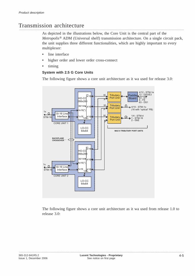
Transmission architecture...................................................................................................................................................................................................................................
As depicted in the illustrations below, the Core Unit is the central part of theMetropolis® ADM (Universal shelf) transmission architecture. On a single circuit pack,the unit supplies three different functionalities, which are highly important to everymultiplexer:
• line interface
• higher order and lower order cross-connect
• timing
System with 2.5 G Core Units
The following figure shows a core unit architecture as it wa used for release 3.0:
The following figure shows a core unit architecture as it wa used from release 1.0 torelease 3.0:
HO-CC
TributaryPort Unit
4/12 - STM-1e12 - DS3/E3
63 - E1
1/4 - STM-4
8 - FE
1x16128
4/16
4/16 Paddle
MAX 9 TRIBUTARY PORT UNITS
4/10 - STM-1o4/16
Board
CORE UNIT 1
36/144
288x288
64x64
TU-3/12
LO-CC64x64LO-CC
W
P4x16(*)
CORE UNIT 264x64
TU-3/12
LO-CC64x64LO-CC
TributaryPort Unit
W
TributaryPort Unit
W
P
P
BACKPLANECROSSOVER
STM-16
STM-16
1 - STM-162 - GbE
HO-CC
1x16 4/16
4/16
4/1636/144
288x288
4x16(*)
128
63 - DS1
(16 with “optical” PB)
SI-16 LineInterface
SI-16 LineInterface
1x
1x
Product description
...................................................................................................................................................................................................................................365-312-841R5.2Issue 1, December 2006
Lucent Technologies - ProprietarySee notice on first page
4-5

System with 10G core unit
The following figure shows a core unit architecture as it wa used for release 3.0:
Product description Transmission architecture
...................................................................................................................................................................................................................................
4-6 Lucent Technologies - ProprietarySee notice on first page
365-312-841R5.2Issue 1, December 2006

Product description Transmission architecture
...................................................................................................................................................................................................................................365-312-841R5.2Issue 1, December 2006
Lucent Technologies - ProprietarySee notice on first page
4-7

Switch function...................................................................................................................................................................................................................................
All cross-connections are switched on the Core Unit. The 10G Core Units (272/128)and the 2.5G Core Unit (64/32 respectively 272/128 (Quad STM-16 core unit (4xSTM-16 SFP CC-272/128)) have a cross-connect that consists of two parts: a higherorder and a lower order cross-connect part. The Core Units can connectn VC-4s fromthe higher order to the lower order cross-connect part, wheren is the number after the“/” of a core units denotation (example: 10G Core Unit (CC-272/128)).
The following types of cross-connections are possible on both Core Units:
• unidirectional
• bidirectional
• loopback
• multi-cast
The following types of traffic can be cross-connected:
• VC-4-16c
• VC-4-4c
• VC-4
• VC-3
• VC-12
Higher and lower order cross-connect parts are interconnected via an internalcross-connect bus that is 32, 64or 128 bidirectional VC-4s wide.
VC11 cannot be cross-connected. The DS1 signal is mapped into a VC11 but thentransported and cross-connected on TU-12 level.
The VC-4-16c, VC-4-4c and VC-4 traffic only passes the higher order switch matrix.Grooming and aggregation of Lower Order traffic requires VC-3 and VC-12 trafficpasses both the higher and lower order switch matrices.
Flexible routing and cross-connecting of VC-4, VC-4-4c, VC-4-16c, VC-3 and VC-12between line port↔ line port, line port↔ tributary port, and tributary port↔tributary port is supported.
Tributary and line interface circuit packs are directly connected to the higher ordercross-connect via STM-1 equivalent signals (AU-4).Metropolis® ADM (Universalshelf) uses both, STM-1 (EQSTM-1) and STM-4 (TXI622) equivalent signals.
Higher order cross-connect
The higher order cross-connect switches VC-4s. Other functions of the higher ordercross-connect are:
• VC-4 SNC protection switching
• STM-16 and STM-64 MS-SPRing protection
• STM-1, STM-4, STM-16 or STM-64 MSP
• equipment protection for tributary units
Product description
...................................................................................................................................................................................................................................
4-8 Lucent Technologies - ProprietarySee notice on first page
365-312-841R5.2Issue 1, December 2006

• non-intrusive monitoring of VC-4s
• broadcasting.
Lower order cross-connect
The lower order cross-connect switches/grooms VC-3s and VC-12s. Other functions ofthe lower order cross-connect are:
• lower order SNC protection
• non-intrusive monitoring of lower order VCs
• lower order broadcasting.
• VC-4 termination.
2.5G application
Depending on the core units to be used the 2.5G application comprises differenttranmission capacities.
2.5G Core Unit (CC-68/32)
With the 2.5G Core Unit theMetropolis® ADM (Universal shelf) has a total switchingcapacity of 68 x 68 VC-4 equivalents (9 x 4 + 2 x 16). The two Line Interfaces on thisUnit each have STM-16 capacity (32 VC-4 equivalents). The nine Tributary Port Unitseach have STM-4 capacity (36 VC-4 equivalents in total).
The 2.5G Core Unit contains a lower order switch matrix (LO-CC) for VC-3 andVC-12 connectivity. This switch matrix has a capacity of 32 x 32 VC-4 equivalents (5Gbps). The total capacity of the higher order switch matrix (HO-CC) is 100 x 100VC-4 equivalents (2x16 + 9x4 + 32).
4x 2.5G Core Unit
With the 4x 2.5G Core Unit theMetropolis® ADM (Universal shelf) has a totaltransmission capacity of 272x272 VC-4 equivalents (42.3 Gbps). The eight LineInterfaces on this Unit each have STM-16 capacity (128 VC-4 equivalents). The nineTributary Port Units each can either have STM-4 or STM-16 capacity (36 or 144 VC-4equivalents).
68 x 68 HO, 32 x 32 LO VC-4 Equivalent or272 x 272 HO, 128 x 128 LO VC-4 Equivalent
Cross-connect Unit
Tributaries(9 x 16 x VC-4)
VC-3/12matrix
64
VC-4matrix
Aggregate(16 x VC-4)
Aggregate(16 x VC-4)
Cross-connect Unit
Tributaries(9 x 4 x VC-4)-
VC-3/12matrix
VC-4matrix
Aggregate(16 x VC-4)
Aggregate(16 x VC-4)
32 (128)
16 /64
16 /64
36 / 144
Product description Switch function
...................................................................................................................................................................................................................................365-312-841R5.2Issue 1, December 2006
Lucent Technologies - ProprietarySee notice on first page
4-9

The 4x 2.5G Core Unit contains a lower order switch matrix for VC-3 and VC-12connectivity (LO-CC). This switch matrix has a capacity of 128x 128 VC-4 equivalents(20 Gbps). The total capacity of the higher order switch matrix (HO-CC) is 400 x 400VC-4 equivalents (8x16 + 9x16 + 128).
10G application
Depending on the core units to be used the 10G application comprises differenttranmission capacities.
10G Core Unit (CC-272/64)
With the 10G Core Unit theMetropolis® ADM (Universal shelf) has a totaltransmission capacity of 272x272 VC-4 equivalents (42.3 Gbit/s). The two LineInterfaces on this Unit each have STM-64 capacity (128 VC-4 equivalents). The nineTributary Port Units each can either have STM-4 or STM-16 capacity (36 or 144 VC-4equivalents).
The 10G Core Unit contains a lower order switch matrix for VC-3 and VC-12connectivity (LO-CC). This switch matrix has a capacity of 64 x 64 VC-4 equivalents(10 Gbit/s). The total capacity of the higher order switch matrix (HO-CC) is 336 x 336VC-4 equivalents (2x64 + 9x16 + 64).
10G Core Unit (CC-272/128)
With the 10G Core Unit theMetropolis® ADM (Universal shelf) has a totaltransmission capacity of 272x272 VC-4 equivalents (42.3 Gbit/s). The two LineInterfaces on this Unit each have STM-64 capacity (128 VC-4 equivalents). The nineTributary Port Units each can either have STM-4 or STM-16 capacity (36 or 144 VC-4equivalents).
The 10G Core Unit contains a lower order switch matrix for VC-3 and VC-12connectivity (LO-CC). This switch matrix has a capacity of 128x 128 VC-4 equivalents(20 Gbit/s). The total capacity of the higher order switch matrix (HO-CC) is 400 x 400VC-4 equivalents (2x64 + 9x16 + 128).
Add/drop capacity
Refer to“Circuit pack capacities” (p. 6-7).
272 x 272 HO, 64 x 64 LO VC-4 Equivalent or272 x 272 HO, 128 x 128 LO VC-4 Equivalent
Cross-connect Unit
6464
Tributaries(9 x 16 x VC-4)
VC-3/12matrix
64
144
VC-4matrix
Aggregate(16 x VC-4)
Aggregate(16 x VC-4)
Cross-connect Unit
6464
Tributaries(9 x 16 x VC-4)
VC-3/12matrix
64 / 128
144
VC-4matrix
Aggregate(64 x VC-4)
Aggregate(64 x VC-4)
Product description Switch function
...................................................................................................................................................................................................................................
4-10 Lucent Technologies - ProprietarySee notice on first page
365-312-841R5.2Issue 1, December 2006

Shelf configurations...................................................................................................................................................................................................................................
The Metropolis® ADM (Universal shelf) is part of Lucent Technologies’ nextgeneration of SDH equipment. The overall system requirements of compact design andflexibility were given special attention, particular in the mechanical design of thesystem.
Subrack
The Metropolis® ADM (Universal shelf) consists of the following slots:
• 2 slots for the Core Units
• 9 universal slots for tributary units (optical and electrical)
• 1 slot for the System Controller Unit
The dimensions of a fully equippedMetropolis® ADM (Universal shelf) subrack are925 × 495 × 270 mm (H × W × D), which includes I/O modules and cable routing.This subrack is designed for front access so that all the connectors can be accessedfrom the front panel. One fan unit is considered as mandatory unit for the 2.5G and the10G application; therefore space for fans is reserved in the middle and bottom of thesubrack. The fan at the bottom of the subrack is optional, the fan in the middle ismandatory.
The figure below schematically shows theMetropolis® ADM (Universal shelf) subrack.Abbreviations used are explained in the table below.
Product description
...................................................................................................................................................................................................................................365-312-841R5.2Issue 1, December 2006
Lucent Technologies - ProprietarySee notice on first page
4-11
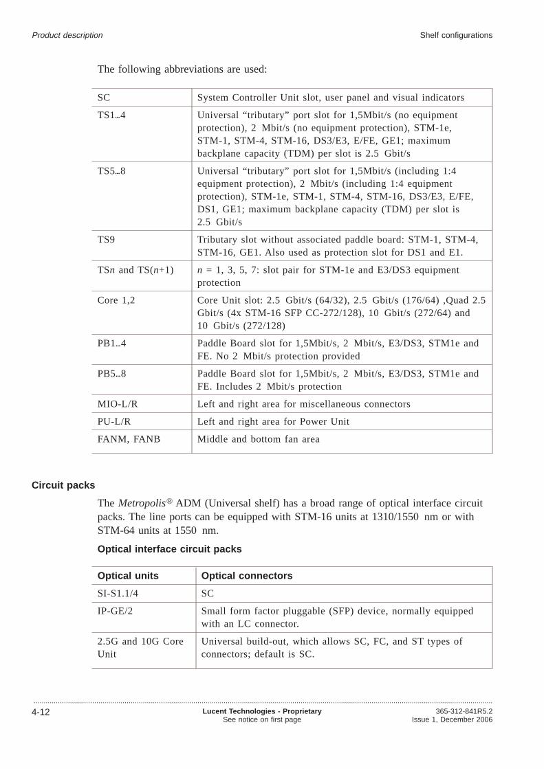
The following abbreviations are used:
SC System Controller Unit slot, user panel and visual indicators
TS14 Universal “tributary” port slot for 1,5Mbit/s (no equipmentprotection), 2 Mbit/s (no equipment protection), STM-1e,STM-1, STM-4, STM-16, DS3/E3, E/FE, GE1; maximumbackplane capacity (TDM) per slot is 2.5 Gbit/s
TS58 Universal “tributary” port slot for 1,5Mbit/s (including 1:4equipment protection), 2 Mbit/s (including 1:4 equipmentprotection), STM-1e, STM-1, STM-4, STM-16, DS3/E3, E/FE,DS1, GE1; maximum backplane capacity (TDM) per slot is2.5 Gbit/s
TS9 Tributary slot without associated paddle board: STM-1, STM-4,STM-16, GE1. Also used as protection slot for DS1 and E1.
TSn and TS(n+1) n = 1, 3, 5, 7: slot pair for STM-1e and E3/DS3 equipmentprotection
Core 1,2 Core Unit slot: 2.5 Gbit/s (64/32), 2.5 Gbit/s (176/64) ,Quad 2.5Gbit/s (4x STM-16 SFP CC-272/128), 10 Gbit/s (272/64) and10 Gbit/s (272/128)
PB14 Paddle Board slot for 1,5Mbit/s, 2 Mbit/s, E3/DS3, STM1e andFE. No 2 Mbit/s protection provided
PB58 Paddle Board slot for 1,5Mbit/s, 2 Mbit/s, E3/DS3, STM1e andFE. Includes 2 Mbit/s protection
MIO-L/R Left and right area for miscellaneous connectors
PU-L/R Left and right area for Power Unit
FANM, FANB Middle and bottom fan area
Circuit packs
The Metropolis® ADM (Universal shelf) has a broad range of optical interface circuitpacks. The line ports can be equipped with STM-16 units at 1310/1550 nm or withSTM-64 units at 1550 nm.
Optical interface circuit packs
Optical units Optical connectors
SI-S1.1/4 SC
IP-GE/2 Small form factor pluggable (SFP) device, normally equippedwith an LC connector.
2.5G and 10G CoreUnit
Universal build-out, which allows SC, FC, and ST types ofconnectors; default is SC.
Product description Shelf configurations
...................................................................................................................................................................................................................................
4-12 Lucent Technologies - ProprietarySee notice on first page
365-312-841R5.2Issue 1, December 2006

Optical units Optical connectors
SI-L16.1 C2/1 andSI-L16.2 C2/1
Universal build-out, which allows SC, FC, and ST types ofconnectors; default is SC.
STM-64 optical line-port units
Description
S-64.2b/3b (1550 nm, ITU-T G.691)
L-64.2b/3 (1550 nm, ITU-T G.691)
SI-I64.1r (1310 nm, very short reach 10G 600 m)
U-64.2c, (1550 nm very long haul line interface 120 km)-
L-64.2c/3 (1550 nm , ITU-T G.691)
S-64.2b/3b (1550 nm, ITU-T G.691)
SI-I64.1r (1310 nm, very short reach 10G 600 m)
V-64.2 line interface (1550 nm, with compatible optics for 120km span width)
STM-16 optical line-port units
Description
L-16.1 (1310 nm, ITU-T G.957)
L-16.2/3 (1550 nm, ITU-T G.957)
4 x STM-16 SFP CC-272/128 (SI-16 SFP C2/4) unit (item code: LKA48) comprisingthe following interface variants:
• L- 16.2/ 3 (1550nm, 80km)
• L- 16.1 (1310nm, 40km)
• I- 16 (1310nm, 2km)
• CWDM (80 km, 4 colours)
• CWDM (40 km, 4 colours)
1 x STM-16 SFP CC-176/64 (SI-16 SFP C3/1) unit (item code: LKA481)
1 x STM-16 VH CC-176/64 OBA (SI-16SFP/C,) unit (item code: LKA482).
Optical interfaces for tributaries
Description
L-16.1 (1310 nm, ITU-T G.957)
L-16.2/3 (1550 nm, ITU-T G.957)
S-4.1 (1310 nm, ITU-T G.957)
Product description Shelf configurations
...................................................................................................................................................................................................................................365-312-841R5.2Issue 1, December 2006
Lucent Technologies - ProprietarySee notice on first page
4-13

Description
L-4.2 (1550 nm, ITU-T G.957)
S-1.1 (1310 nm, ITU-T G.957)
L-1.2 (1550 nm, ITU-T G.957)
STM- 1/ 4 trib unit
• Increased density:– up to • 16 STM-1o or– 4 STM-4o or– 12 STM-1e ports
• Mixed operation STM- 1o/ 4o
• Optical ports are SFP- based
• Optical interface variants (SFP):S-1.1, L-1.1, L-1.2, S-4. 1, L-4.1, L- 4.2 (i. e. 15 Km, 40 Km, 80 Km)
• Optional 1+ 1 Equipment Protection for STM- 1e
IP-GE/2 - pluggable optics (SFP based) for:
• 1000BASE-SX (850 nm short haul multi-mode; IEEE 802.3 clause 38)
• 1000BASE-LX (1310 nm long haul multi-mode; IEEE 802.3 clause 38)
• 1000BASE-ZX (1550 nm long haul single-mode; IEEE 802.3 clause 38)
IP-LAN12 - pluggable optics (SFP based) for:
• OM100B-LX (100BASE-LX (1310 nm SMF; 10km)
STM-16 optical tributary interfaces:
Apparatuscode
Description
LKA50 1XSTM-16 SFP
OMI16 SFP 2G5-I16 / 2 km
OML16.1 SFP 2G5-L16.1 40 km
OM2G5-S16.1 SFP 2G5-S16.1 15 km
OM2G5-L16.2 SFP 2G5-L16.2/3 80 km
OM16CL51 STM-16 cWDM SFP color 13 (1510nm) 80 km
OM16CL53 STM-16 cWDM SFP color 14 (1530nm) 80 km
OM16CL55 STM-16 cWDM SFP color 15 (1550nm) 80 km
OM16CL57 STM-16 cWDM SFP color 16 (1570nm) 80 km
OM16CS51 STM-16 cWDM SFP color 13 (1510nm) 40 km
OM16CS53 STM-16 cWDM SFP color 14 (1530nm) 40 km
OM16CS55 STM-16 cWDM SFP color 15 (1550nm) 40 km
OM16CS57 STM-16 cWDM SFP color 16 (1570nm) 40 km
Product description Shelf configurations
...................................................................................................................................................................................................................................
4-14 Lucent Technologies - ProprietarySee notice on first page
365-312-841R5.2Issue 1, December 2006

STM-4 & 1 optical tributary interfaces:
Apparatuscode
Description
LKA39 SI-1/12 Multi-STM Main Board (12*STM-1e,16*STM-1o, 4*STM-4)
PBP8 PB-STM-1o/6 PB 6xSTM-1o
OMS4.1 SFP 622M-S4.1 SFP SH 15km S-4.1
OM622M-L4.1 SFP 622M-L4.1 SFP LH 40km L-4.1
OM622M-L4.2 SFP 622M-L4.2 SFP LH 80km L-4.2
OM155M-S1.1 SFP 155M-S1.1 SFP SH 15km S-1.1
OM155M-L1.1 SFP 155M-L1.1 SFP LH 40km L-1.1
OM155M-L1.2 SFP 155M-L1.2 SFP LH 80km L-1.2
OM155SF1 SFP SFW-1490BD-D
Downstream SFP STM-1/4/GbE 1490nm singlefibre working 15km
OM155SF2 SFP SFW-1310BD-U
Upstream SFP STM-1/4/GbE 1310nm singlefibre working 15km
Electrical tributary circuit packs
Description
PI-E1/63: 2 Mbit/s
PI-DS1/63: 1.5 Mbit/s
PI-E3DS3/12: 34 and 45 Mbit/s
SI-1/4 (STM-1e): 155 Mbit/s
IP-LAN/8 (Ethernet LAN): 10/100 Base-T
Paddle boards
The tables below informs about Protection and impedance conversion using paddleboards (PB)
PB name Item code Comcode Description
PB-E1e/P75/63 PBE3 109192120 Unprotected orprotected 75Ωapplications, 63channels, enhancedversion
Product description Shelf configurations
...................................................................................................................................................................................................................................365-312-841R5.2Issue 1, December 2006
Lucent Technologies - ProprietarySee notice on first page
4-15

PB name Item code Comcode Description
PB-E1/P75/63 PBE3D 109585620 Unprotected orprotected 75Ωapplications, 63channels, enhancedversion
PB-E1/120/63 PBE4 109199521 Unprotected orprotected 120Ωapplications, 63channels, highdensity paddleboard
PB-E1/P120/63 PBE41 109536763 Unprotected orprotected 120Ωapplications, 63channels, highdensity paddleboard
PB name Item code Comcode Description
PB-DS1/P100/63 PBE12 109464222 Unprotected orprotected 100Ωapplications, 63channels, highdensity paddleboard
PB name Item code Comcode Description
PB-E3DS3/75/12 PBG4 108905597 Unprotected 75Ωapplications, 12channels
PB-E3DS3/75/P12 PBP1 109209262 Protected 75Ωapplications, 12channels
PB name Item code Comcode Description
PB-1/P75/4S PBG2 108746033 Unprotected 75Ωapplications, 4channels
Product description Shelf configurations
...................................................................................................................................................................................................................................
4-16 Lucent Technologies - ProprietarySee notice on first page
365-312-841R5.2Issue 1, December 2006

PB name Item code Comcode Description
PB-1/P75/4D PBP2 109209270 Protected 75Ωapplications, 4channels
PB-1/75/12S PBP5 109285478 Unprotected 75Ωapplications, 12channels
PB-1/P75/12D PBP6 109285486 Protected 75Ωapplications, 12channels
PB-STM-1o/6 PBP8 109481333 6 SFP cages forSTM-1o interfaces
PB name Item code Comcode Description
PB-LAN/100/8 PBG1 108720228 Unprotected10/100Base—TLAN 8 channels
PB-OPT/12 SFP PBO12 109553693 Paddle Brd.12xLAN SFP
PB-LAN100/12 PBL12 109553685 Paddle Brd.12xLAN 100 Ohm
Printed circuit boards
The Metropolis® ADM (Universal shelf) subrack can accommodate a number of circuitpacks. The dimensions of the circuit packs are 336 mm high and 220 mm deep. Thecircuit packs are connected to the backplane by pins only: special coax and powerconnectors are not used. All optical connections are located at the front of the circuitpack.
There is a latching mechanism on the top and bottom of the circuit pack for insertionor extraction. LEDs are positioned in the area between the circuit pack’s latches.
Apart from the System Controller Unit, which has several LEDs, all other front packshave one LED for alarm purposes.
The figure below schematically shows the front view of the circuit packs.
Product description Shelf configurations
...................................................................................................................................................................................................................................365-312-841R5.2Issue 1, December 2006
Lucent Technologies - ProprietarySee notice on first page
4-17

Paddle boards
A variety of paddle boards exists for connection between customer cabling and thebackplane in case of protection or impedance conversion. The electrical componentsneeded for conversion and/or protection are optional and will be located on the paddleboard. The paddle boards are accessible at the front side of the backplane and arelocated at the left and right side of the subrack.
For each electrical tributary unit, these paddle boards have to be used in the case ofimpedance conversion and/or equipment protection. The paddle boards can be pluggedin on the front of the extended back panel of the subrack in such a way that cables canenter the subrack from the left and the right side.
The paddle boards have a guiding system to prevent damage to connectors and alatching mechanism for insertion and extraction.
Interconnection system
Type of interconnections:
• Optical connections
• Circuit pack to back panel
• Back panel to paddle boards
• Paddle boards to customer cable
• Miscellaneous I/O on back panel to customer cable
• Power connections.
Product description Shelf configurations
...................................................................................................................................................................................................................................
4-18 Lucent Technologies - ProprietarySee notice on first page
365-312-841R5.2Issue 1, December 2006

The customer connectors form the physical interface for the permanent and semipermanent supervision interfaces of theMetropolis® ADM (Universal shelf). Asuppress button on the SC and the station station alarm disconnect button makes itpossible to suppress alarms without opening the EMC boundary of the subrack.
Customer interface
Customer interfaces that are available:
• timing
• station alarms
• miscellaneous discretes
• access to overhead bytes
• network management interfaces.
Customer connectors
The table below gives an overview of the customer connectors.
Connector Connector type Use
Power (XB1,XB2) 3W3 D-sub powerconnector, Male
Power connection
Station Clock IN 1 D-SUB 9P MALE External Timing input 1
Station Clock IN 2 D-SUB 9P MALE External Timing input 2
Station Clock OUT 1 D-SUB 9PFEMALE
External Timing output 1
Station Clock OUT 2 D-SUB 9PFEMALE
External Timing output 2
BTALM D-SUB 9PFEMALE
Bay (rack) top alarms
MDI D-SUB 15PFEMALE
Miscellaneous input
MDO D-SUB 9PFEMALE
Miscellaneous output
Station Alarm D-SUB 15PFEMALE
Station Alarm cabling
V11-1 D-SUB 15PFEMALE
Access to user overhead bytes,V.11 provisionable
V11-2 D-SUB 15PFEMALE
Access to user overhead bytes,V.11 provisionable
G.703-1 and G.703-2 D-SUB 9PFEMALE
Access to user overhead bytes,G.703 provisionable
Product description Shelf configurations
...................................................................................................................................................................................................................................365-312-841R5.2Issue 1, December 2006
Lucent Technologies - ProprietarySee notice on first page
4-19

Connector Connector type Use
Q-LAN RJ 45 OMS connection, (Twisted-PairEthernet)
10 BASE-T LAN
CIT-F RJ 45 ITM CIT connection,
H-LAN RJ 45 10/100 BASE-T LAN (for futureuse)
Connectors
The electrical connectors are located on the paddle board. The front-accesse connectorsmake implementation and maintenance easier and quicker. All the optical interfaces arelocated on the front side of the circuit packs. The following table shows an overviewof interface types, cables and connectors.
Interface type Cable type Connector type onconnector plate
Number of cables/ connectors perslot
1,5 Mbit/s STP 2 mm FCI - BP50 16 × 8 = 128 cables
2 Mbit/s COAX or STP 2 mm FCI - BP50 16 × 8 = 128 cables
34/45 Mbit/s COAX coax 1.6/5.6 connector,female
24 coax
STM-1e COAX coax 1.6/5.6 connector,female
8 coax
10/100 BASE-TLAN
UTP RJ45 8 or 12 UTP
1 GbE/ZX2 SM fibre LC 4 fibres
100 BASE-LX10 SM fibre LC 24 fibres
STM-1o SM-fibre SC 8 fibres
STM-4o SM-fibre SC 2 fibres
STM1o trib highdensity packs
SM-fibre LC 16 fibres (10 ofthese on the packitself, the other 6 ona STM-1opaddleboard:).
STM4o trib highdensity packs
SM break outcable
LC 4 fibres
1 GbE/SX2 SM-fibre /MMF-fibre
LC 4 fibres
1 GbE/LX2 SM fibre LC 4 fibres
Product description Shelf configurations
...................................................................................................................................................................................................................................
4-20 Lucent Technologies - ProprietarySee notice on first page
365-312-841R5.2Issue 1, December 2006

Interface type Cable type Connector type onconnector plate
Number of cables/ connectors perslot
STM-16 SM-fibre SC or FC/PC 2 fibres
STM-16 SFPs(used in LKA48,LKA482/482)
SM-fibre LC 2 fibres
STM-64 SM-fibre SC or FC/PC 2 fibres
FC type connections
SC type connections
Product description Shelf configurations
...................................................................................................................................................................................................................................365-312-841R5.2Issue 1, December 2006
Lucent Technologies - ProprietarySee notice on first page
4-21

ST type connections
LC type connections
FCI - BP50
The following figure shows an 2 mm FCI with COAX or STP cable:
Product description Shelf configurations
...................................................................................................................................................................................................................................
4-22 Lucent Technologies - ProprietarySee notice on first page
365-312-841R5.2Issue 1, December 2006

Cables and fibres
The Metropolis® ADM (Universal shelf) requires a number of cable types to connectthe system. The cables can be:
• 2 Mbit/s 75 Ω 8 coax cable AWG30, 2GE564*
• 2 Mbit/s 120 Ω 8 (shielded) twisted pair AWG26, 2GE134*
• 1,5 Mbit/s 100 Ω 8 (shielded) twisted pair AWG26, 2GE134*
• 34/45 Mbit/s single coaxial cable 75Ω• 155 Mbit/s single coaxial cable 75Ω• LAN4 twisted pair CAT5 cable
• misc. I/O several types of wires
• power 4 mm2 power wires
• STM-1 optical cables
• STM-4 optical cables
• STM-16 optical cables
• STM-64 optical cables.
Important! The use of multi-mode fibers with STM-1 SFPs is never considered asthe S-1.1 or other STM-1 or STM-4 interfaces are only specified for single-modeapplications. Using multi-mode fibers (MMFS) should never be used for tests andoptical loops. This will damage the receiver.
Product description Shelf configurations
...................................................................................................................................................................................................................................365-312-841R5.2Issue 1, December 2006
Lucent Technologies - ProprietarySee notice on first page
4-23

Circuit packs...................................................................................................................................................................................................................................
2.5G Core Units 64/32
The 2.5G Core Units can be placed in the core slots of theMetropolis® ADM(Universal shelf) system. The units have a red fault LED and a green activity LED.
The unit’s main functions are:
• type L-16.1, 1310 nm long haul line interface for a 40 km target distance(LKA24)
• type L-16.2/3, 1550 nm long haul line interface for a 80 km target distance(LKA25)
• OS, RS, MS termination and NIM (VC-n, with n = 12, 3, 4)
• 64 × 64 STM-1 eqv. higher order cross-connecting (VC-4/4-4c)
• 32 × 32 STM-1 eqv. lower order cross-connecting (VC-n, with n = 12, 3)
• timing collection, generation, and distribution.
2.5G Core Unit 272/128 (LKA48)
The SI-16SFP C2/4 2.5G Core Unit can be placed in the core slots of theMetropolis®
ADM (Universal shelf) system. The unit has a red fault LED and a green activity LED.
The unit’s main functions are:
• four STM-16, Small Formfactor Plugable (SFP) interfaces,
• SFP with optical amplifier for 40dB reach
• OS, RS, MS termination and NIM (VC- n , with n =12, 3, 4),
• 272x272 STM-1 eqv. higher-order cross connecting (VC-4/ 4-4c/4-16c),
• 128x128 STM-1 eqv. lower-order cross connecting (VC- n , with n =12, 3 andVC-11 (when mapped as TU-12)),
• timing collection, generation, and distribution.
• This unit can be equipped with 0, 1, 2, 3, or 4 hot-plugable STM-16 interfaces.
• This unit supports timing reference selection from just one arbitrary STM-16 port.
Product description
...................................................................................................................................................................................................................................
4-24 Lucent Technologies - ProprietarySee notice on first page
365-312-841R5.2Issue 1, December 2006

2.5G Core Unit application for STM-16 Long Span on G.652 fiber
This application is reached by using the SI-16SFP C2/4 2.5G Core Unit together withan SFP with optical amplifier for 41dB reach.
2.5G Core Unit 176/64 (LKA481)
The SI-16 SFP C3/1, 1 port STM-16 unit can be placed in the core slots of the system.The unit has one red fault LED plus one for the SFP.
The unit’s main functions are:
• 1 STM-16, Small Formfactor Plugable (SFP) interface,
• OS, RS, MS termination and NIM (VC- n , with n =12, 3, 4),
• 176 x 176 STM-1 eqv. higher-order cross connecting (VC-4/4-4c/4-16c),
• 64x64 STM-1eqv. lower-order cross connecting (VC- n , with n =12, 3 and VC-11(when mapped as TU-12)),
• timing collection, generation, and distribution.
41dB,2850ps/nm
2.5dB path penalty
DCM-80
WES-OA
--SFP
LKA482G5 CWDM
TX
LKA482G5 CWDM-
SFP-RXT-16
Product description Circuit packs
...................................................................................................................................................................................................................................365-312-841R5.2Issue 1, December 2006
Lucent Technologies - ProprietarySee notice on first page
4-25

• This unit can be equipped with 0 or 1 hot-plugable STM-16 SFP.
• This unit supports timing reference selection from the STM-16 port.
2.5G Core Unit 176/64 (LKA482)
The SI-16 VH C3/1 OBA, 1 port STM-16 unit with Very Long Haul can be placed inthe core slots of the system. The unit has an integrated OBA. The optical link betweenLD and OBA allows the inclusion of an external DCF. The unit has one red fault LEDplus one for the SFP.
The unit’s main functions are:
• 1 STM-16, Small Formfactor Plugable (SFP) interface,
• OS, RS, MS termination and NIM (VC- n , with n =12, 3, 4),
• 176 x 176 STM-1 eqv. higher-order cross connecting (VC-4/4-4c/4-16c),
• 64x64 STM-1eqv. lower-order cross connecting (VC- n , with n =12, 3 and VC-11(when mapped as TU-12)),
• timing collection, generation, and distribution.
• This unit can be equipped with 0 or 1 hot-plugable STM-16 SFP.
• This unit supports timing reference selection from the STM-16 port.
2.5G Core Unit application for STM-16 Long Span on G.652 fiber
This application is reached by using the SI-16 VH C3/1 OBA 2.5G Core Unit togetherwith an SFP with onboard optical amplifier.
The DCM is needed to extend the tolerable chromatic dispersion to a value of 2540ps/nm within the bandwidth of the 1551nm CWDM channel. For G.653 and G.655fibre or shorter distances of G.652 fibre where the dispersion is less than 1600 ps/nmno DCM is needed.
,DCM
LKA482
PF
LKA482
only needed for G.652fibre
STM-16CWDMSFP
TX
RX
STM-16CWDMSFPTX
RX
OBA
OBA
DCM
only needed for G.652fibre
Product description Circuit packs
...................................................................................................................................................................................................................................
4-26 Lucent Technologies - ProprietarySee notice on first page
365-312-841R5.2Issue 1, December 2006

The following table gives an overview to the different scenarios and the selection ofthe right DCM:
Chromatic DispersionRange [ps/nm] @1551nm
Required DCM Type
Min. Max.
0 1600 no
1400 1760 DCM-10
1600 1920 DCM-20
1700 2070 DCM-30
1800 2230 DCM-40
2000 2390 DCM-50
2200 2540 DCM-60
0 1000 no This values are onlyrelevant if the transmissioncable has very high loss orif additional component lossapplies.
800 1160 DCM-10
900 1320 DCM-20
1000 1475 DCM-30
1200 1630 DCM-40
1400 1790 DCM-50
1500 1950 DCM-60
10G Core Units
The 10G Core Units can be placed in the core slots of theMetropolis® ADM(Universal shelf) system. The units have a red fault LED and a green activity LED.
Type L-64.2b/3 (LKA26), 1550 nm long haul line interface for a 80 km targetdistance
The unit’s main functions are
• OS, RS, MS termination and NIM (VC4, VC4-4c, VC4–16c)
• 272 × 272 STM-1 eqv. higher order cross-connecting (VC-4/4-4c/4–16c)
• 64 × 64 STM-1 eqv. lower order cross-connecting and NIM (VC-n, with n = 12,3)
• timing collection, generation, and distribution.
Type S-64.2b/3b (LKA27), 1550 nm short haul line interface for a 40 km targetdistance
The unit’s main functions are
• OS, RS, MS termination and NIM (VC4, VC4-4c, VC4–16c)
• 272 × 272 STM-1 eqv. higher order cross-connecting (VC-4/4-4c/4–16c)
Product description Circuit packs
...................................................................................................................................................................................................................................365-312-841R5.2Issue 1, December 2006
Lucent Technologies - ProprietarySee notice on first page
4-27
• 64 × 64 STM-1 eqv. lower order cross-connecting and NIM (VC-n, with n = 12,3)
• timing collection, generation, and distribution.
Type I-64.1r (LKA47), 1310 nm intra-office interface, for 600 m target distance
The unit’s main functions are
• OS, RS, MS termination and NIM (VC4, VC4-4c, VC4–16c)
• 272 × 272 STM-1 eqv. higher order cross-connecting (VC-4/4-4c/4–16c)
• 64 × 64 STM-1 eqv. lower order cross-connecting and NIM (VC-n, with n = 12,3)
• timing collection, generation, and distribution.
Type L64.2c2/3 (LKA28) 1550 nm long haul line interface, for a 120 km targetdistance
L-64.2c/3 is achieved without booster amplifier.
The unit’s main functions are
• OS, RS, MS termination and NIM (VC4, VC4-4c, VC4–16c)
• 272 × 272 STM-1 eqv. higher order cross-connecting (VC-4/4-4c/4–16c)
• 128 × 128 STM-1 eqv. lower order cross-connecting and NIM (VC-n, with n = 12,3)
• timing collection, generation, and distribution.
Type U64.2c2/3 (LKA281) 1550 nm long haul line interface, for up to 150 kmtarget distance
Similar to LKA28, but with SBS suppression on, in order to support interworking withan external Optical Amplifier:
The unit’s main functions are
• OS, RS, MS termination and NIM (VC4, VC4-4c, VC4–16c)
• 272 × 272 STM-1 eqv. higher order cross-connecting (VC-4/4-4c/4–16c)
• 128 × 128 STM-1 eqv. lower order cross-connecting and NIM (VC-n, with n = 12,3)
• timing collection, generation, and distribution.
10G Core Unit application for STM-64 Long Span with optical booster amplifieronly
This application is reached by using the U64.2c2/3 line interface (LKA281) togetherwith external collocated Booster Amplifier only.
Product description Circuit packs
...................................................................................................................................................................................................................................
4-28 Lucent Technologies - ProprietarySee notice on first page
365-312-841R5.2Issue 1, December 2006

10G Core Unit application for STM-64 Long Span on G.652 Fiber (2a/2)
This application is reached by using the U64.2c2/3 line interface (LKA281) togetherwith external collocated Booster- and Pre-Amplifier and an external collocated DCM.
10G Core Unit application for STM-64 Long Span on G.652 Fiber (2b/2)
This application is reached by using the U64.2c2/3 line interface (LKA281) togetherwith external collocated Booster- and Pre-Amplifier and an external collocated DCM.
10G Core Unit application for STM-64 Long Span on G.652 Fiber (2c/2)
This application is reached by using the U64.2c2/3 line interface (LKA281) togetherwith external collocated Booster- and Pre-Amplifier and an external collocated DCM.
G.655 or G.652LKA281
136 km of G.655 fiber with 0.275 dB/kmor 94 km with G.652 fiber
LKA281,OBA
(max.: 1600 ps/nm with max. 37.5 dB or1000 ps/nm with max. 38.5 dB)
28 dB...36 dB ,2860 ps/nm
DCM-80LKA281
WES-OA
130 km at .275 dB/km attenuation
PF LKA281,T-10 LBO
DCMdepends on
link dispersion
LBOdepends onDCM loss
WES-OA
31 dB...39 dB ,2860 ps/nm
DCM-80LKA281
WES-OA
141 km at .275 dB/km attenuation
PF LKA281,T-13 LBO
DCMdepends on
link dispersion
LBOdepends onDCM loss
WES-OA
Product description Circuit packs
...................................................................................................................................................................................................................................365-312-841R5.2Issue 1, December 2006
Lucent Technologies - ProprietarySee notice on first page
4-29

Type S64.2b/3b (LKA29) 1550 nm short haul line interface for a 40 km targetdistance
The unit’s main functions are
• OS, RS, MS termination and NIM (VC4, VC4-4c, VC4–16c)
• 272 × 272 STM-1 eqv. higher order cross-connecting (VC-4/4-4c/4–16c)
• 128 × 128 STM-1 eqv. lower order cross-connecting and NIM (VC-n, with n = 12,3)
• timing collection, generation, and distribution.
Type I64.1r (LKA49) 1310 nm intra-office interface, for 600 m target distance
The unit’s main functions are
• OS, RS, MS termination and NIM (VC4, VC4-4c, VC4–16c)
• 272 × 272 STM-1 eqv. higher order cross-connecting (VC-4/4-4c/4–16c)
34 dB...42 dB ,2860 ps/nm
DCM-80LKA281
WES-OA
152 km at .275 dB/km attenuation
PF LKA281,T-16 LBO
DCMdepends on
link dispersion
LBOdepends onDCM loss
WES-OA
Product description Circuit packs
...................................................................................................................................................................................................................................
4-30 Lucent Technologies - ProprietarySee notice on first page
365-312-841R5.2Issue 1, December 2006

• 128 × 128 STM-1 eqv. lower order cross-connecting and NIM (VC-n, with n = 12,3)
• timing collection, generation, and distribution.
Type V-64.2/3 line interface (LKA350), with compatible optics for up to 120 kmspan width
Depending on the used 10G transponder used in the interface, different span width canbe supported.
• LKA350 units of the series numbers S1:1 to S1:4 supports span widths of up to110 km on G.652 fibers
• LKA350 units of the series S5:5 number supports span widths of up to 125 km onG.652 fibers and attenuation limited distances on G.655 fiber
The unit’s main functions are
• OS, RS, MS termination and NIM (VC4, VC4-4c, VC4–16c)
• 272 × 272 STM-1 eqv. higher order cross-connecting (VC-4/4-4c/4–16c)
• 128 × 128 STM-1 eqv. lower order cross-connecting and NIM (VC-n, with n = 12,3)
• timing collection, generation, and distribution.
Product description Circuit packs
...................................................................................................................................................................................................................................365-312-841R5.2Issue 1, December 2006
Lucent Technologies - ProprietarySee notice on first page
4-31

10G Core Unit application (LKA350 Series S1:1 to S1:4) for STM-64 Long Span onG.652 fiber
This application is reached by using the V-64.2/3 line interface (LKA350 S1:1 to S1:4)together with an integrated booster amplifier and an external Dispersion CompensationModule (DCM).
10G Core Unit application (LKA350 Series S5:5) for STM-64 Long Span on G.652and G.655 fiber
This application is reached by using the V-64.2/3 line interface (LKA350 S5:5) withintegrated booster amplifier. No external Dispersion Compensation Module (DCM)needed.
,Path penalty 2dBLKA350 LKA350
Transmission Fiber(max.: 1800 ps/nm @ 1539 nmor 110 km G.652, 21 ... 33 dB)
DCM-10
PrecompensationDCM-10 (for > 100 km G.652fiber only)
OATransmitter Receiver
Booster
Product description Circuit packs
...................................................................................................................................................................................................................................
4-32 Lucent Technologies - ProprietarySee notice on first page
365-312-841R5.2Issue 1, December 2006

10G Core Unit application for STM-64 Long Span on G.652 fiber, interworking ofLKA350 (series S1:1 to S1:4) with LKA350 (series S5:5)
This interworking scenario can be reached by using both interface (LKA350 (S1:1 toS1:4) and LKA350 (S1:5) together with integrated booster amplifiers and externalDispersion Compensation Modules (DCM).
1.5 Mbit/s plesiochronous interface unit (LKA16)
The PI-DS1/63 unit can be placed in one of the tributary slots of theMetropolis®
ADM (Universal shelf) system. In combination with a paddle board, the unit provides63 bidirectional 1.5 Mbit/s interfaces. The unit has a red fault LED. The unit can beplaced in tributary slots TS1 TS9.
,Path penalty 2dB
LKA350 S5:5
Transmission Fiber (G.652, G.655)(max.: 2000 ps/nm @ 1533.3 nm or125 km G.652, 21 ... 33 dB)
Direct optical connection usedbeetween both ports
OATransmitter Receiver
Booster
LKA350 S5:5
,Path penalty 2dB
LKA350 S1:1 to S1:4
LKA350 S5:5
Transmission Fiber(max.: 1800 ps/nm @ 1539 nmor 110 km G.652, 21 ... 33 dB)
DCM-10
PrecompensationDCM-10 (for > 100 km G.652fiber only)
OATransmitter Receiver
Booster
DCM-10
OA Transmitter
Booster
Receiver
PrecompensationDCM-10 (for > 100 km G.652fiber only)
Path penalty 2dB
Product description Circuit packs
...................................................................................................................................................................................................................................365-312-841R5.2Issue 1, December 2006
Lucent Technologies - ProprietarySee notice on first page
4-33

According to [G.783]e, the unit implements:
• the PDH physical interface (PPI)
• lower order path adaptation (LPA)
• lower order path termination (LPT)
• higher-order path adaptation (HPA)
• higher-order path termination (HPT)
• the EQSTM1 backplane interface
2 Mbit/s plesiochronous interface unit (LKA2)
The PI-E1/63 unit can be placed in one of the tributary slots of theMetropolis® ADM(Universal shelf) system. In combination with a paddle board, the unit provides 63bidirectional 2 Mbit/s interfaces. The unit has a red fault LED. The unit can be placedin tributary slots TS1 TS9.
According to [G.783]e, the unit implements:
• the PDH physical interface (PPI)
• lower order path adaptation (LPA)
• lower order path termination (LPT)
• higher-order path adaptattion (HPA)
• higher-order path termination (HPT)
• the EQSTM1 backplane interface
34 Mbit/s / 45 Mbit/s plesiochronous interface unit (LKA8/LKA8B)
This PI-E3DS3/12 unit can be placed in tributary slots [1 8 ] of the Metropolis®
ADM (Universal shelf) system. On this unit there are twelve integrated switchablebidirectional external interfaces that comply with either the G.703-8 specification for34 Mbit/s (E3) or the G.703-5 specification for 45 Mbit/s (DS3).
In the egress direction, AU-4 pointer processing and VC-4 termination (POHprocessing) for four AU-4s takes place. This is followed by TU-3 pointer processing,VC-3 termination (again POH processing), desynchronization and conversion toHDB3/B3ZS of the twelve 34/45 Mbit/s signals.
In the ingress direction exactly the inverse processes happen.
On this unit any mixture of twelve 34/45 Mbit/s interfaces can be realized. One unitoccupies one of the slots that are reserved for tributary-port units. The unit has a redfault LED. The unit can be placed in tributary slots TS1 TS8. The choice betweenE3 and DS3 modes will be made per interface. By default all interfaces will run inDS3 mode.
STM-1e synchronous interface unit (LKA3)
This SI-1e/4 unit can be placed in the tributary slots of theMetropolis® ADM(Universal shelf) system. The unit has four bidirectional external CMI interfaces thatcomply with the G.703-15 specification for 155 Mbit/s (STM-1e). The unit provides
Product description Circuit packs
...................................................................................................................................................................................................................................
4-34 Lucent Technologies - ProprietarySee notice on first page
365-312-841R5.2Issue 1, December 2006

CMI encoding/decoding, pointer processing, and RS/MS termination functionality for 4STM-1s. The unit operates in AU-4 mode. The unit has a red fault LED. The unit canbe placed in tributary slots TS1 TS8.
For STM-1e see also“Parent pack for STM-4, STM-1o and STM-1e (LKA39)”(p. 4-36).
STM-1o synchronous interface units (LKA6, LKA13)
The STM-1o synchronous interface units can be placed in the tributary slots of theMetropolis® ADM (Universal shelf) system. The units support four optical STM-1interfaces (1310 nm short haul or 1550 nm long haul)). The unit has a red fault LED.The units can be placed in tributary slots TS1 TS9.
The unit’s main functions are:
• type SI-S1.1/4 short haul interface
• type SI-L1.1/4 long haul interface
• OS, RS and MS termination
• 1+1 equipment protection (EQP) with a mate unit (only in combination with MSP)
• 1+1 MSP with a mate unit
• conversion between AU-3s and TU-3s.
For STM-1o see also“Parent pack for STM-4, STM-1o and STM-1e (LKA39)”(p. 4-36).
STM-4 synchronous interface units (LKA11 / LKA14)
The STM-4 synchronous interface units can be placed in the tributary slots of theMetropolis® ADM (Universal shelf) system. The units support one optical STM-4interface (1310 nm short haul or 1550 nm long haul). The units have a red fault LED.The units can be placed in tributary slots TS1 TS9.
The unit’s main functions are:
• type SI-S-4.1/1 short haul interface
• type SI-L4.2/1 long haul interface
• OS, RS and MS termination
• 1+1 equipment protection (EQP) with a mate unit (only in combination with MSP)
• 1+1 MSP with a mate unit
• conversion between AU-3s and TU-3s.
STM-16 synchronous interface units
The STM-16 synchronous interface units can be placed in one of the 9 tributary slotsof the Metropolis® ADM (Universal shelf) system. The units provide access to oneoptical interface and occupy one tributary slot.
Product description Circuit packs
...................................................................................................................................................................................................................................365-312-841R5.2Issue 1, December 2006
Lucent Technologies - ProprietarySee notice on first page
4-35
Type SI L-16.1/1 1310 nm long haul interface for a 40 km target distance (LKA23)
The unit’s main functions are:
• The unit supports the universal optical connector (default SC connector) and has ared fault LED.
• OS, RS, MS termination
• support of VC-4/4-4c/4-16c↔ AUG16 adaptation
Type SI L-16.2/1 1550 nm long haul interface for an 80 km target distance(LKA22)
The unit’s main functions are:
• The unit supports the universal optical connector (default SC connector) and has ared fault LED.
• OS, RS, MS termination
• support of VC-4/4-4c/4-16c↔ AUG16 adaptation
Type SI-x16 SFP/1 (LKA50)
The unit supports one SFP with one optical interface. These SFP’s are the same as onthe 4 x STM-16 SFP CC-272/128 core unit. This unit supports the LC connector andhas a red fault LED plus one per SFP cage.
The unit’s main functions are:
• support of 1 STM-16 SFP,
• SFP with optical amplifier for 40dB reach
• OS, RS, MS termination
• support of VC-4/4-4c/4-16c↔ AUG16 adaptation
Parent pack for STM-4, STM-1o and STM-1e (LKA39)
This unit (SI-1/M) supports up to
• 4 STM-4 SFP’s (on the pack itself),
• 16 STM-1 SFP’s,(10 of these SFP’s on the pack itself, the other 6 on a STM-1o paddleboard:P.224.2)
• 12 STM-1e ports on a STM-1e paddleboard (unprotected: P.224.0, 1+1 protected:P.224.1).
The unit has a red LED plus one per SFP cage.
Note: Only the ports 1, 5, 9 and 10 can be used for STM-4.
Product description Circuit packs
...................................................................................................................................................................................................................................
4-36 Lucent Technologies - ProprietarySee notice on first page
365-312-841R5.2Issue 1, December 2006

Data interface unit LAN Fast Ethernet Mb-EOS (IP–LAN/8) (LKA4)
This LAN unit (IP-LAN/8) is a tributary port unit of theMetropolis® ADM (Universalshelf) system. At the system side, the unit provides a double EQSTM-1(~300 Mbit/s)interface towards the cross-connect (CC) function. WAN capacity of up to 260 Mbit/sis available. At the external interface side, the unit provides 8 Ethernet interfaces at10/100 Mbit/s (10BaseT/100BaseT). The Ethernet connectors are located on the paddleboards. The unit has a red fault LED. The unit can be placed in tributary slots TS1 TS8.
E/FE switched Card (LKA412)
This LAN unit is a tributary port unit of theMetropolis® ADM (Universal shelf)system. This unit supports L2 Ethernet switch and mapping of Ethernet traffic intoVC-3-Xv (x=1..9) , VC-12-Xv (x=1..63) and VC-4-Xv (x=1..3) according GFP, IEEEtagging , VLAN trunking, LCAS and LPT.
At the system side, the unit provides a 3x TXI-622Mb interface towards thecross-connect (CC) function. Up to total 1200 Mb/s WAN capacity is available and oneWAN port capacity is in Max. 100Mbps. All 12x Ethernet interfaces can operate at fullwirespeed (100Mb/s).
At the external interface side, via paddle boards, the unit can provide 12 Ethernetinterfaces, like 10/100BASE-T and Ethernet SFP.
Product description Circuit packs
...................................................................................................................................................................................................................................365-312-841R5.2Issue 1, December 2006
Lucent Technologies - ProprietarySee notice on first page
4-37
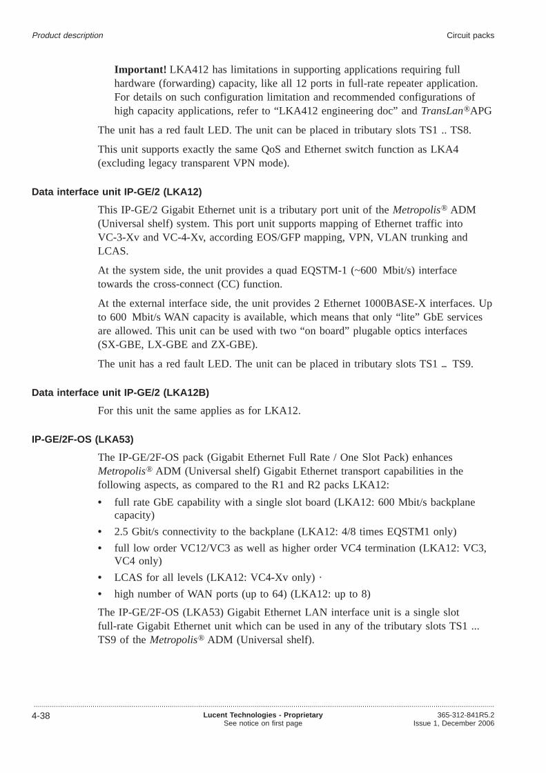
Important! LKA412 has limitations in supporting applications requiring fullhardware (forwarding) capacity, like all 12 ports in full-rate repeater application.For details on such configuration limitation and recommended configurations ofhigh capacity applications, refer to “LKA412 engineering doc” andTransLan®APG
The unit has a red fault LED. The unit can be placed in tributary slots TS1 .. TS8.
This unit supports exactly the same QoS and Ethernet switch function as LKA4(excluding legacy transparent VPN mode).
Data interface unit IP-GE/2 (LKA12)
This IP-GE/2 Gigabit Ethernet unit is a tributary port unit of theMetropolis® ADM(Universal shelf) system. This port unit supports mapping of Ethernet traffic intoVC-3-Xv and VC-4-Xv, according EOS/GFP mapping, VPN, VLAN trunking andLCAS.
At the system side, the unit provides a quad EQSTM-1 (~600 Mbit/s) interfacetowards the cross-connect (CC) function.
At the external interface side, the unit provides 2 Ethernet 1000BASE-X interfaces. Upto 600 Mbit/s WAN capacity is available, which means that only “lite” GbE servicesare allowed. This unit can be used with two “on board” plugable optics interfaces(SX-GBE, LX-GBE and ZX-GBE).
The unit has a red fault LED. The unit can be placed in tributary slots TS1 TS9.
Data interface unit IP-GE/2 (LKA12B)
For this unit the same applies as for LKA12.
IP-GE/2F-OS (LKA53)
The IP-GE/2F-OS pack (Gigabit Ethernet Full Rate / One Slot Pack) enhancesMetropolis® ADM (Universal shelf) Gigabit Ethernet transport capabilities in thefollowing aspects, as compared to the R1 and R2 packs LKA12:
• full rate GbE capability with a single slot board (LKA12: 600 Mbit/s backplanecapacity)
• 2.5 Gbit/s connectivity to the backplane (LKA12: 4/8 times EQSTM1 only)
• full low order VC12/VC3 as well as higher order VC4 termination (LKA12: VC3,VC4 only)
• LCAS for all levels (LKA12: VC4-Xv only) ·
• high number of WAN ports (up to 64) (LKA12: up to 8)
The IP-GE/2F-OS (LKA53) Gigabit Ethernet LAN interface unit is a single slotfull-rate Gigabit Ethernet unit which can be used in any of the tributary slots TS1 ...TS9 of theMetropolis® ADM (Universal shelf).
Product description Circuit packs
...................................................................................................................................................................................................................................
4-38 Lucent Technologies - ProprietarySee notice on first page
365-312-841R5.2Issue 1, December 2006
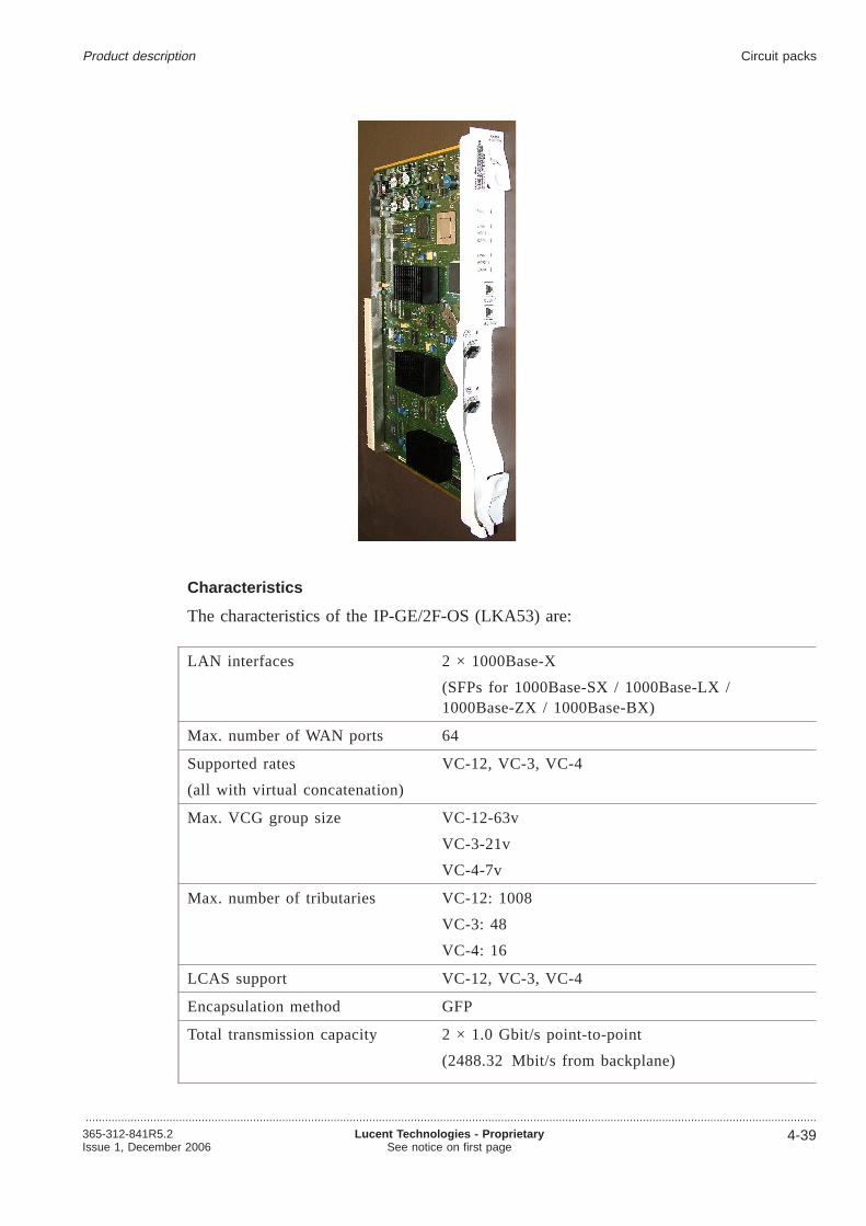
Characteristics
The characteristics of the IP-GE/2F-OS (LKA53) are:
LAN interfaces 2 × 1000Base-X
(SFPs for 1000Base-SX / 1000Base-LX /1000Base-ZX / 1000Base-BX)
Max. number of WAN ports 64
Supported rates
(all with virtual concatenation)
VC-12, VC-3, VC-4
Max. VCG group size VC-12-63v
VC-3-21v
VC-4-7v
Max. number of tributaries VC-12: 1008
VC-3: 48
VC-4: 16
LCAS support VC-12, VC-3, VC-4
Encapsulation method GFP
Total transmission capacity 2 × 1.0 Gbit/s point-to-point
(2488.32 Mbit/s from backplane)
Product description Circuit packs
...................................................................................................................................................................................................................................365-312-841R5.2Issue 1, December 2006
Lucent Technologies - ProprietarySee notice on first page
4-39

Important! The IP-GE/2F-OS (LKA53) Gigabit Ethernet unit can only be used incombination with
• an LKA21 System Controller, and
• a 2.5-Gbit/s or 10-Gbit/s core unit of type SI-L64.2 C1/1 (LKA26), SI-I64.1rC1/1) (LKA47), SI-S64.2 C1/1 (LKA27), SI-16SFP C2/4 (LKA48), SI-16 SFPC3/1(LKA481), SI-16 VH C3/1 OBA (LKA482), SI-L64.2 C2/1 (LKA28),SI-U64.2 C2/1 (LKA281), SI-S64.2 C2/1 (LKA29), SI-I64.1r C2/1 (LKA49), orSI-V64.2 C2/1 (LKA350).
Gigabit Ethernet port LEDs
On the faceplate of the Gigabit Ethernet circuit packs, there are two additional LEDs(“LINK” and “DATA”) associated with each external Ethernet port (LAN port) whichprovide the following information:
• The green LED labelled “LINK”” indicates the link status, i.e. the green LED is litif the corresponding link is active.The LAN port status LED behaves slightly differently on IP-GE/2F-OS whencompared to other packs. Upon some transmission defect conditions, the LED doesnot blink with 1 Hz (as the other units do), but with 15 Hz.
• The yellow LED labelled “DATA” indicates the link activity (transceived data inboth transmission directions).
MRV module
The only supported MRV module byMetropolis® ADM (Universal shelf) is MRVFiber® Driver EM316-GRMAHSH (10/100/1000 Mbps)
MRV equipment comcodes
MRV equipment part Comcode
GRMAHSH-RL
User port Auto-sensing between 10/100/1000Mpbs Copperand SFP Based Fiber, to Redundant Fiber SFP Based Trunk,802.3AH, with IP-Less Remote Management RoHS 5/6Compliant (SW revision - Lucent 1.0
300894011
LU BNDL EU1 GR-RL
Single-slot chassis with internal 200-250 VAC Power Supply(European version), no power cable is provided with Userport Auto-sensing between 10/100/1000Mpbs Copper andSFP Based Fiber, to Redundant Fiber SFP Based Trunk,802.3AH, with IP-Less Remote Management RoHS 5/6Compliant (SW revision - Lucent 1.0)
300894029
Product description Circuit packs
...................................................................................................................................................................................................................................
4-40 Lucent Technologies - ProprietarySee notice on first page
365-312-841R5.2Issue 1, December 2006
MRV equipment part Comcode
LU BNDL DC1 GR-RL
Single-slot Chassis with Internal -48V DC Power Supply.Desk Top with User port Auto-sensing between10/100/1000Mpbs Copper and SFP Based Fiber, toRedundant Fiber SFP Based Trunk, 802.3AH, with IP-LessRemote Management (SW revision - Lucent 1.0)
300894037
Notes:
1. A bundle consists of the MRV Fieber driver module and the chassis.
Supported MRV SW version
MRV DIP switch settings
The MRV DIP switch must be set as follows:
Block Switch Label Supported setting Notes
SW1 1 MX DIS don’t care Ignored by MRV if AUTO==ON.
2 AUTO ON Selects user-port autonegotiationenabled
3 1000Tx don’t care Ignored by MRV if AUTO==ON
4 100Tx don’t care Ignored by MRV if AUTO==ON
5 HDPLX don’t care Ignored by MRV if AUTO==ON
6 CPE EN ON Selects CPE mode
7 LIN EN ON Selects LIN-enabled mode
8 RM DIS OFF Currently reserved for future useby MRV.
SW2 1 NM DIS ON Disables NM write access to theMRV module.
2 LPBK OFF Disables local loopback.
3 PRE EN OFF Currently reserved for future useby MRV.
4 T-AUTO OFF Disables autonegotiation on trunkinterface.
When using this settings, the MRV module is expected to bring up the links as follows,after connecting the equipment and powering up the MRV module:
User Link (P3 for SFP 1000/100 Mbps or P4 for 10/100 Mbps):
• Autonegotiation: on
• Rate: autonegotiated
Product description Circuit packs
...................................................................................................................................................................................................................................365-312-841R5.2Issue 1, December 2006
Lucent Technologies - ProprietarySee notice on first page
4-41

• Duplexity: autonegotiated
• Flow Control: off (will not be negotiated)
Trunk Link (P1):
• Autonegotiation: off
• Rate: 1000
• Duplexity: full
• Flow Control: off
Important! The LKA53 Default Port Mode is “Autonegotiation enabled” !
1.5 Mbit/s paddle board, 100 Ω, protected
The PB-DS1/P100/63.unit can be placed in the PB slots of theMetropolis® ADM(Universal shelf) systems. This PB is an extension of the PI-DS1/63, and provides:
• protection 1:N in case of PI-DS1/63 unit, (in TS9)
• 100 Ω adaption
• simplicity for subscriber cable connections
The board is placed in the I/O slot positions associated with the (worker) tributary slotsand responsible for the protection and connection function for the PI-DS1/63 unit. Thepaddle board can also be used for operation without 1:N protection. The paddle boardhas a red fault LED.
2 Mbit/s paddle board, 75 Ω or 120 Ω protected
The PB-E1/P75/63 (PBE3D) unit and PB-E1/P120/63 (PBE41) unit can be placed inthe PB slots of theMetropolis® ADM (Universal shelf) systems. This PB module is anextension of the PI-E1/63 and provides:
• high density interconnect
• protection 1:N in case of PI-E1/63 unit (in TS9)
• 75 Ω adaption in case of type PB-E1/P75/63
• 120 Ω adaption in case of type PB-E1/P120/63.
The board is placed in the I/O slot positions associated with the (worker) tributary slotsand responsible for the protection and connection function for the PI-E1/63 unit. Thepaddle board can also be used for operation without 1:N protection. The paddle boardhas a red fault LED.
34/45 Mbit/s paddle boards
Paddle boards for 12 × E3/DS3 unprotected interface and 1.6/5.6 connectors (PBG4)
This PB-E3DS3/75/12 unit can be placed in PB slots PB1 PB8 of theMetropolis®
ADM (Universal shelf) system. On this paddle board there are 1.6/5.6 connectors fortwelve bidirectional external HDB3/B3ZS interfaces. These connectors comply with
Product description Circuit packs
...................................................................................................................................................................................................................................
4-42 Lucent Technologies - ProprietarySee notice on first page
365-312-841R5.2Issue 1, December 2006

either the G.703-8 specification for 34 Mbit/s (E3) or the G.703-5 specification for45 Mbit/s (DS3). The paddle board can be used for unprotected interfaces incombination with one unit. The unit has a red fault LED.
Paddle boards for 12 × E3/DS3 interface with 1+1 protection and 1.6/5.6 connectors(PBP1)
This PB-E3DS3/P75/12 unit can be placed in PB slots PB1 PB8 of theMetropolis®
ADM (Universal shelf) system. On this paddle board there are 1.6/5.6 connectors fortwelve bidirectional external HDB3/B3ZS interfaces. These connectors comply with theeither G.703-8 specification for 34 Mbit/s (E3) or the G.703-5 specification for45 Mbit/s (DS3) The paddle board can be used for 1+1 protection in combination withtwo units in two adjacent trib slots (trib slots 1&2, 3&4 and 5&6, 7&8 are allowed).The unit has a red fault LED.
STM-1e paddle boards
The following STM-1e paddle boards are supported:
PB 4 × STM-1e
Paddle board PB-1/P75/4D (PBP2) and PB-1/P75/4S (PBG2) for 4 × STM-1einterfaces with 1+1 protection with 1.6/5.6 connectors. On this paddle board there are1.6/5.6 connectors for four bidirectional external CMI interfaces. These connectorscomply with the G.703-15 specification for 155 Mbit/s (STM-1e). The paddle boardcan be used for 1+1 protection in combination with two units in two adjacent tributaryslots (trib slots 1&2, 3&4, 5&6 and 7&8 are allowed).
PB 12 x STM-1e (unprotected) (PBP5)
On this paddle board 1.6/5.6 connectors for 12 bi-directional external CMI interfaces,complying with G.703-15 specification for 155 Mbit/s (STM-1e), are available. Thisunit supports unprotected STM-1e interfaces only. This board will be used forunprotected applications in combination with units as described in“Parent pack forSTM-4, STM-1o and STM-1e (LKA39)” (p. 4-36). It will be used in the I/O slotpositions belonging to tributary slots TS1 .. TS8. The PB has a red fault LED.
PB 12 x STM-1e (1+1 protected) (PBP6)
On this paddle board 1.6/5.6 connectors for 12 bi-directional external CMI interfaces,complying with G.703-15 specification for 155 Mbit/s (STM-1e), are available. Thepaddle board can be used for 1+1 protection in combination with two units, asdescribed in“Parent pack for STM-4, STM-1o and STM-1e (LKA39)” (p. 4-36), intwo adjacent trib slots (trib slots 1&2, 3&4 and 5&6, 7&8 are allowed). The PB has ared fault LED.
6 x STM-1o paddle board (PBP8)
On this paddle board are 6 SFP cages for STM-1o interfaces. The PB will have adedicated fault LED for each SFP cage plus one for the PB itself.
Product description Circuit packs
...................................................................................................................................................................................................................................365-312-841R5.2Issue 1, December 2006
Lucent Technologies - ProprietarySee notice on first page
4-43

12x10/100BaseT Paddle board for unprotected LAN interfaces (PBL12)
This PB-LAN/100/12 unit can be placed in the I/O slots of theMetropolis® ADM(Universal shelf). This LAN interface paddle board provides RJ45 connectors for 12EtherNet UTP interfaces at 10 Mbit/s/100 Mbit/s(10BaseT/100BaseT). The paddleboard does not perform equipment protection for the Ethernet connections.Each RJ45port has 2 LEDs linked, one green LED for Link status and one yellow LED forActivity status. Thepaddle board will have a red fault LED.For Metropolis(R) ADM(Universal) the unit can be placed in the I/O slots associated with TS1 .. TS8.
12x Ethernet SFP paddle board for unprot. LAN interfaces ( PBO12)
This PB-LAN/opt/12 SFP unit can be placed in the I/O slots of theMetropolis® ADM(Universal shelf). This LAN interface paddle board provides SFP sockets for 12Ethernet electrical / optical interfaces at 10 Mbit/s/100Mbit/s (10/100BASE-T,100BASE-LX10 ). The paddle board does not perform equipment protection for theEthernet connections. Each SFP socket has 3 LEDs linked, one green LED for Linkstatus, one yellow LED for Activity status and one red LED for SFP Fault status. Thepaddle board has a red fault LED. The unit can be placed in the I/O slots associatedwith TS1 .. TS8.
Paddle board-LAN/100/8
This PB-LAN/100/8 unit can be placed in the PB slots of theMetropolis® ADM(Universal shelf) system. This LAN interface paddle board provides connectors for 8Ethernet UTP interfaces at 10/100 Mbit/s (10BaseT/100BaseT). The paddle board doesnot perform equipment protection for the Ethernet connection. Each RJ-45 connectorhas a green link-status LED. The paddle board has a red fault LED.
System Controller Unit (SC)
The System Controller Unit (SC) provides the central control, supervision, and securityfunctions in the network element. For this purpose, it communicates with the functioncontrollers on the individual interface circuit packs.
The System Controller Unit (SC) controls and provisions all circuit packs via a localLAN bus. The SC also provides the external operations interfaces for office alarms,miscellaneous discretes and connections to the overhead channels (a maximum of fouroverhead bytes may be selected for connection to four connectors on theinterconnection box).
The SC also facilitates first line maintenance via several LEDs and buttons on the frontpanel. General status and alarm information is displayed. The System Controller Unithouses the systems’ LEDs and buttons for station alarms. The SC has a red fault LED.Various controls and an F-interface connector, for a local maintenance PC (ITM-CIT),are also located on this panel. The SC communicates with the centralized managementsystem (Navis® OMS). One part of the SC, which routes management informationbetween SDH equipment and the element management system, is the Data Packet
Product description Circuit packs
...................................................................................................................................................................................................................................
4-44 Lucent Technologies - ProprietarySee notice on first page
365-312-841R5.2Issue 1, December 2006

Switch (DPS). Communication is established via the Data Communication Channels(DCC) (= D1-3/D4-12 bytes), within the STM-N section-overhead signals or via one ofthe Q-interfaces of the system.
Information that is destined for the local system is routed to the System ControllerUnit, while other information is routed from the node via the appropriate embeddedchannels of the STM-N line or tributary signals (N= 1, 4, 16 or 64). The OMSmanages theMetropolis® ADM (Universal shelf) at the element level and the networklevel. The ITM-Craft Interface Terminal (ITM-CIT) can be used to manage smallnetworks and for maintenance.
The System Controller Unit is part of the minimum equipment of any systemconfiguration. The SC is needed to store/change all system configuration data and tocontrol many of the automatic processes (e.g. equipment-protection switching) withinthe system. The SC contains the system memory banks. A system cannot start upwithout a System Controller Unit.
When a System Controller Unit is removed from a working system the systemcontinues to operate, but some automatic maintenance actions will no longer takeplace. Although the System Controller Unit is not protected. However this does notrepresent a single point of failure since the SC functionalities are distributed throughthe system and mainly in the Core Units which are equipment protected. This impliesthat in case of a simultaneous SC failure and network link failure, line and pathprotection schemes will still function.
The following figure shows the System Controller unit, LKA21:
Product description Circuit packs
...................................................................................................................................................................................................................................365-312-841R5.2Issue 1, December 2006
Lucent Technologies - ProprietarySee notice on first page
4-45

Synchronization and timing...................................................................................................................................................................................................................................
Timing architecture
The figure below depicts the architecture of the timing function on the 2.5G and 10GCore Units of theMetropolis® ADM (Universal shelf) system. A 1+1 equipmentprotection scheme will be provisioned automatic between the two Core Units.
External timing reference inputs
There are two external timing reference inputs for synchronization purposes. The signalformat can be either 2048 kHz according to the G.703-10 or 2048 kbit/s according tothe G.703-6. The 2048 kbit/s reference signal can be either framed according to G.704or unframed (in that case also AIS is a valid format).
The desired format can be selected for each input. The impedance of the interfaces(75 Ω coaxial or 120Ω symmetrical) is determined at installation according tocustomer prescription (but equal for both interfaces). Even if only one timing unit ispresent in the system, two input signals can be applied.
SSM support (Synchronization Status Message)
If the selected format of an external synchronization signal is 2048 kbit/s with G.704framing, the reception and transmission of SSM’s in a user assignable Sa bit (4 to 8)location can optionally be supported. Bit 4 is default.
Excessive reference frequency offset mapped to reference fail
If the active reference of theMetropolis® ADM (Universal shelf) is outside theacceptable range (at least ±11 ppm), the reference is declared failed.
ReferenceSelection
MainPLLSEL
ReferenceSelection
MainPLLSEL
Driver
2 MHz2 Mb/s
2 MHz2 Mb/s
from/to other core unit
6
2
2
#1
#2
Product description
...................................................................................................................................................................................................................................
4-46 Lucent Technologies - ProprietarySee notice on first page
365-312-841R5.2Issue 1, December 2006

By comparing the frequencies of all assigned references to the frequencies of theinternal oscillator on both timing units, it can be decided, in case an excessivefrequency difference is detected, whether a timing reference or the internal oscillator ofone of the timing units is off-frequency. In the latter case that unit is declared failed.
Reference signal switching
Two synchronization inputs of the same type (e.g. two external synchronization signalsor two 2 Mbit/s tributaries or 2 STM-N tributary signals) can be set up to have anon-revertive 1+1 protection relation. Such a pair counts as a single synchronizationreference for the internal clock or the external synchronization output. Manual andautomatic switching are supported.
If two STM-N inputs form an MSP pair, they also count as one syn-chronizationreference, following the MSP switch. If restoration by means of a reference signalswitch is possible this method will prevail over protection through timing linkswitching.
Timing link switching for internal clock
A large number of possible input references or outputs from reference signal switchprocesses can be assigned to the timing link switch that selects the reference for theinternal clock. Input references are either suitable synchronization inputs directlyassigned to the timing link switch or the active reference from a reference signalswitch pair or MSP pair.
Limitations in the assignment are:
• two external synchronization signals (or one reference signal switch pair)
• two timing signals derived from the line interfaces
• four from the tributary interfaces can be assigned at any time (where referencesignal switching pairs count as two assignments, but MSP pairs count as oneassignment).
Automatic and manual switching (forced, manual and lock-out) between the assignedreferences is possible. A wait-to-restore timer (0 to 60 minutes, programmable in 1minute increments, default 5 minutes) is present to time re-qualification of asynchronization source after a failure. Can be reset manually.
Timing link switching for external synchronization output
A number of possible input references or outputs from reference signal switchprocesses can be assigned to the timing link switch that selects the reference for theexternal synchronization outputs.
The limitations are:
• at most two timing signals derived from the line interfaces and .
• at most four timing signals derived from the tributary interfaces can be assigned atany time (where reference signal switching pairs count as two assignments, butMSP pairs count as one assignment)
Product description Synchronization and timing
...................................................................................................................................................................................................................................365-312-841R5.2Issue 1, December 2006
Lucent Technologies - ProprietarySee notice on first page
4-47

Automatic and manual switching (forced, manual and lock-out) between the assignedreferences is possible. A wait-to-restore timer (0 to 60 minutes, programmable in 1minute increments, default 5 minutes) is present to time re-qualification of asynchronization source after a failure. Can be reset manually.
Support of ETSI SSM algorithm
Automatic protection switching between the references that are available to both timinglink switches (for the internal oscillator and the external synchronization output) issupported. The switching algorithm is according to ETSI ETS 300417-6. The algorithmacts on those inputs which are assigned to participate and to which the customer canassign a certain priority. The SSM algorithm can be turned off. In that case only theassigned priorities are considered to determine the active reference.
It is possible to assign a certain SSM value (overriding the received SSM, if any) toany synchronization reference signal that can be made available to the SSM selectionalgorithm.
External timing reference outputs
“Timing architecture” (p. 4-46)shows two output connection points with signals thatcan be used to synchronize other equipment. The format is either 2048 kHz accordingto G.703-10 or 2048 kbit/s according to G.703-6, with or without a G.704 frame.
The desired format can be selected for both outputs or an output disabled altogether.The impedance of the interfaces (75Ω coaxial or 120Ω symmetrical) is determined atinstallation according to customer prescription (but equal for both interfaces). Even ifonly one timing unit is present in the system, two output signals are available.
In case the framed 2048 kbit/s format is selected for the external synchronizationoutput signal, the user can force a DNU (Do Not Use for synchronization) message tobe transmitted in the Sa -bit channel selected for SSMs.
DNU (Do Not Use)
In case the framed 2048 kbit/s format is selected for the external synchronizationoutput signal, a DNU (Do Not Use for synchronization) message can be transmitted inthe Sa bit channel selected for SSMs (Synchronization Status Message).
Automatic squelching of the external synchronization output (2 Mbit/s or 2 MHz)
The external synchronisation output(s) will automatically be squelched as soon asits/their associated Quality Level (QL) drops below a certain threshold, which can beset by the customer. Squelching is implemented by turning the 2048 kHz or unframed2048 kbit/s signal off. For framed 2048 kbit/s the squelching method is user selectablebetween AIS substitution or forwarding of the DNU message.
In case a framed 2048 kbit/s format is selected as external synchronization outputsignal, the customer can select the squelching method to be substitution of AIS orinsertion of a DNU message in the applicable Sa-bit channel.
Product description Synchronization and timing
...................................................................................................................................................................................................................................
4-48 Lucent Technologies - ProprietarySee notice on first page
365-312-841R5.2Issue 1, December 2006

External timing interfaces
The external timing interfaces are located on the MIO-R unit.
There are two types of MIO-R units:
• A unit supporting 2 Mbit/s (framed and unframed) and 2 MHz timing inputs /outputs
• A unit supporting 64 kHz inputs / 6 MHz outputs (called MIOR-J).
Each one of these units supports two inputs and two outputs. Only one of these unitscan be equipped in a system. For further details please refer to“External timingreference inputs” (p. 4-46)and“External timing reference outputs” (p. 4-48).
64 kHz to 2048 kHz conversion (via the MIOR-J unit)
The MIOR-J unit converts two independent 64 kHz signals coming from outside totwo independent 2048 kHz signals towards backplane. The 110 ohm 64 kHz signals,which serve as system station clock inputs, can be either (64 kHz + 8 kHz) or (64 kHz+ 8 kHz + 400 Hz). The conversion is done by means of transformer, CPLD, 2048kHz PLLs. The 2048 kHz signals are then sent to core units which can be used forsystem timing source. The signal status is monitored by CPLD. Once Loss of Signal(LOS) happens on 64 kHz, the related 2048 kHz output will be disabled (highimpedance) and LOS reported through I2C bus; once Loss of Lock (LOL) happens inthe conversion process, the related 2048 kHz output will not be disabled as the Coreunit(s) can handle it: either the signal still can be accepted and therefore used or if not,system raises certain alarm, the LOL will be reported through I2C bus. 4.2
2048 kHz to 6312 kHz conversion (via the MIOR-J unit)
The MIOR-J unit converts two independent 2048 kHz signals coming from backplaneto two independent 6312 kHz signals towards outside. The 2048 kHz signals aresystem station clock outputs. The conversion is done by means of CPLD, 6312 kHzPLLs and transformers. The 75 ohm 6312 kHz signals, can be used to synchronizeother Network Elements. The signal status is monitored by CPLD. Once Loss of Signal(LOS) happens on 2048 kHz, the related 6312 kHz output will be disabled (highimpedance) and LOS reported. Once Loss of Lock (LOL) happens in the conversionprocess, the related 6312 kHz output will be disabled (high impedance) and LOLreported through.
PLL
The external timing reference outputs are driven by two PLLs (phase lock loops),which are shown in the figure Timing architecture:
• the main PLL; the central clock driving six external timing outputs
• the External PLL, driving two external timing output ports.
Product description Synchronization and timing
...................................................................................................................................................................................................................................365-312-841R5.2Issue 1, December 2006
Lucent Technologies - ProprietarySee notice on first page
4-49

The signal driving the individual PLLs can be selected as follows:
• for the MAIN PLL: out of either the sync. signal provided by the other (protect)SI-16 Core Unit or SI-64 Core Unit or out of the reference signal selected by thereference selector shown to its left.
• for the EXT. PLL: out of either the sync. signal provided by the MAIN PLL or outof the reference signal selected by the reference selector shown to its left.
Select timing reference
Hence it is possible to select individual timing references for the outgoing station clocksignals and for the internal reference clock signals. Reference selections are softwareselectable by the user.
Timing modes
As shown in next figure, the system can be provisioned for the followingsynchronization conditions / modes:
• free runningfrom an internal oscillator (FR)
• internal timing from an incoming line or tributary signal
• external timing, timed from an external 2 MHz or 2 Mbit/s clock signal
• hold-over mode(HO).
The figure below illustrates the operation when the free running mode is selected.
The user can select the system to function in any one of the three sync. modesspecified above. This selection can be done by software (user input) or be fullyautomatically. If set to automatic, the system will automatically switch to hold-overmode if the input timing reference signal fails.
Free Running operation (FR)
The Metropolis® ADM (Universal shelf) is designed to operate without any externalsynchronization reference in the free running mode. In the free running mode (switchset to FR), the SI-16 or SI-64 Core Unit derives timing from an internal station
Hold-overmemory
PLL
LO
HO
FR
Product description Synchronization and timing
...................................................................................................................................................................................................................................
4-50 Lucent Technologies - ProprietarySee notice on first page
365-312-841R5.2Issue 1, December 2006

equipment clock (SEC) oscillator. The internal SEC oscillator’s long-term accuracy ishigher than 4.6 ppm. The SI-16 or SI-64 Core Unit generates and distributes the timingsignals to the interface circuit packs.
Locked mode (LO)
Locked to selected reference (switch to LO).
Locked-to-line or tributary timing mode
In the locked-to-line or tributary timing mode (switch set to LO), the system derivestiming from the incoming line or tributary signals. In turn, the SI-16 or SI-64 CoreUnit generates timing signals and distributes them to the transmission circuit packs.
The signal references are continuously monitored for error-free operation. If theworking line or tributary reference in a protected system becomes corrupted, the SI-16or SI-64 timing circuit selects the protection line/tributary reference without causingservice degradation. If both references fail, the PLL circuit holds the on-boardoscillator frequency at the last good reference sample while the references are repaired,(hold-over mode: switch set to HO automatically!).
This mechanism is provided so that operation with or without an external clock can beeasily accommodated. In both timing modes, the SI-16 or SI-64 Core Unit can stillprovide two synchronization outputs to other central office equipment.
Locked to external timing reference operation
Locked to External timing reference Operation (with hold-over). In the external timingmode (switch set to LO), each SI-16 or SI-64 circuit pack accepts a 2 MHz or2 Mbit/s synchronization reference signal from a 4.6 ppm or better station clock. Thesereferences synchronize the local terminal.
Within the SI-16 or SI-64 circuit pack, a highly stable PLL circuit removes anytransient impairments from the 2 MHz or 2 Mbit/s reference for improved jitterperformance. If the external reference fails, the PLL circuit on the SI-16 or SI-64circuit pack holds the on-board oscillator frequency at the last reference sample whilethe external clock signal is repaired (hold-over mode: switch set to HO automatically!).
Hold-over mode (HO)
As described above, the system provides a so-called hold-over mode to ensure that thetiming of the system is as accurate as possible when all timing references fail. Ittherefore memorizes the most recently used timing frequency in a hold-over memoryon-board the 2.5G or 10G 64 Core Units. The SI-16 or SI-64 timing circuit pack isequipped with an internal clock with Stratum-3 Hold-over Performance according toITU-T recommendation G.813 option 1 with in addition a frequency stability of 0.37ppm over the first 24 hours of hold-over.
Product description Synchronization and timing
...................................................................................................................................................................................................................................365-312-841R5.2Issue 1, December 2006
Lucent Technologies - ProprietarySee notice on first page
4-51

Back-up hold-over
In locked mode of operation, if no acceptable references are available, the internalclock will switch to the back-up hold-over state.
Back-up timing
To keep the software on all circuit packs alive when there is no synchronization signalfrom one or both 2.5G or 10G 64 Core Units, the System Controller Unit (SC)distributes a back-up timing signal. This timing allows for the execution of circuit packtests and equipment loop-backs. The SC timing signal is distributed to all slots of thesystem. The accuracy of the back-up timing signal is approximately 50 ppm. When theback-up clock is selected, the circuit packs switch all transmission ports to SQUELCHmode.
Clock/synchronous distribution on circuit packs
The following figure gives an overview of timing at circuit-pack level.
One of the following three timing sources is selected:
• Reference signal selected by the working SI-16 or SI-64 circuit pack
• Reference signal selected by the protecting SI-16 or SI-64 circuit pack
• Back-up clock signal derived from the SC.
All timing signals are checked for availability and if a signal fails, then the message“Timing Fail” (including the missing source) is sent to the on-board FunctionController (FC). Then the FC immediately initiates the command to switch to thesystem’s backup timing and all transmission ports are switched off (squelch mode).
fromPTworking
fromPTprotecting
from SCback-up clock
SelectMux
Freq.Divider
PulseDetector
PLL
: N
N MHz
N kHz
155 MHz
155 MHz
Product description Synchronization and timing
...................................................................................................................................................................................................................................
4-52 Lucent Technologies - ProprietarySee notice on first page
365-312-841R5.2Issue 1, December 2006
Switching between the input references is non-revertive. A PLL on the circuit packitself locks to the selected timing source and supplies the circuit pack with allnecessary frequencies.
Product description Synchronization and timing
...................................................................................................................................................................................................................................365-312-841R5.2Issue 1, December 2006
Lucent Technologies - ProprietarySee notice on first page
4-53

System control and management...................................................................................................................................................................................................................................
Optical Management System OMS
The System Controller (SC) controls and provisions all circuit packs via a local LANbus. The SC also provides the external operations interfaces for office alarms,miscellaneous discrete inputs and outputs and connections to the overhead channels.
The SC also facilitates first line maintenance by several LEDs and buttons on the frontpanel. General status and alarm information is displayed. Various controls and an Finterface connector, for a local maintenance PC (ITM-CIT), are also located on thispanel. The SC communicates with the centralized management system (OMS).Communication is established via so-called Data Communication Channels ((DCC=D1-3/D4-12 bytes), within the STM-N section overhead signals or via one of theQ-interfaces of the system. Information destined for the local system is routed to theSystem Controller, while other information is routed from the node via the appropriateembedded channels of the STM-N line or tributary signals. The Optical ManagementSystem OMS manages the system at the Network Level. The ITM-Craft interfaceterminal (ITM-CIT) can be used for managing single network elements and formaintenance.
The OMS manages theMetropolis® ADM (Universal shelf) at element level andnetwork level. The ITM-Craft Interface Terminal (ITM-CIT) can be used for managingsmall networks and for maintenance.
Software download
It is possible to download software from OMS to the System Controller to replace oradd applications in the local database. During download the old software is stored inthe memory as a backup. This means that after download, two complete softwareversions are available on the SC. The Local Craft Terminal (ITM-CIT) can alsodownload the software.
Management features
The most important management features are:
• Optical Management System OMS
• OSI stack with IS-IS level 2 routing and a flexible NSAP address
• D4-D12 and D1-D3 support on optical STM-n interfaces
• 8 × miscellaneous discrete input (MDI) and 4 × miscellaneous discrete output(MDO)
• Remote login on the ITM-CIT from theMetropolis® ADM (Universal shelf) to theMetropolis® ADM (Compact shelf), theWaveStar® ADM 16/1, theWaveStar® TM1 and theMetropolis® AM / Metropolis® AMS.
Product description
...................................................................................................................................................................................................................................
4-54 Lucent Technologies - ProprietarySee notice on first page
365-312-841R5.2Issue 1, December 2006

Power...................................................................................................................................................................................................................................
The system power supply is able to provide 650 W power in the range –40 V to –72 VDC, respectively –48 V to –60 V DC nominal.
Power Unit (PU)
The Power Unit performs a limited part of the filtering of electrical noise (in bothdirections). The major part of the filtering is done on the circuit pack itself. Protectionagainst transients on the power feeders is located in the Power Unit. Each power filteracts on one of the incoming supplies (A or B).
If a Power Unit is not present, the corresponding power feed is not available to thesystem. Protection against reverse polarity will be provided by the individual circuitpack (OR-ing diodes). The PU contains auxiliary voltage sources that are used in thesystem. The unit has a red fault LED and a green power LED. No single point offailure must be present in the system, in the case of a duplicated power feed (exceptfor the backplane).
Power distribution
Optionally the power supply of the rack can be provided by a Power Distribution Panel(PDP) at the top of the rack.
Power indicators
LED indicators
• Green: feeder power
• Red: central auxiliary supply failure.
Product description
...................................................................................................................................................................................................................................365-312-841R5.2Issue 1, December 2006
Lucent Technologies - ProprietarySee notice on first page
4-55
Cooling...................................................................................................................................................................................................................................
Cooling is provided by a plug-in fan unit placed on the middle of the sub-rack. Fanspull air through a filter below the circuit packs and force it through the sub-rack frombottom to top. An air flow baffle with air filter is integrated in the lower part of thesubrack to prevent the intake of particles or exhaust air from below.
Fan unit
Two fan units each of which contains two fans are integrated in those subracks forwhich the dissipation under fully loaded conditions could otherwise cause the thermallimits of the components to be exceeded. Proper cooling is still ensured if one of thefour fans is failing. A subrack containing two fan units meets the acoustic noiserequirements in P.301.1.
One fan unit is considered as mandatory unit for the 2.5G and the 10G application;therefore space for the fans is reserved in the middle and bottom of the subrack. Ifneeded, a second fan can optionally be ordered.
Fan controller
The fan unit includes two fans and a microcontroller that senses air flow, airtemperature and fan faults. The microcontroller adjusts the speed of the fans tocompensate for the failure of a fan or to conserve power when full air flow is notneeded. It also reports the status of the fan unit to the shelf controller.
Proper cooling is still ensured if one of the four fans is failing. Failed fans cannot bereplaced individually. A complete fan unit must be replaced. This is achieved withoutinterruption of service.
Air filter
The subrack also contain an air filter which can be easily replaced or cleaned (bothtypes are available). The air filter, located below the subrack, must be replaced orcleaned under regular conditions once every 3 months to ensure the proper cooling.
Important! The fan unit must be installed and operating in a shelf before anycircuit packs are installed.
Product description
...................................................................................................................................................................................................................................
4-56 Lucent Technologies - ProprietarySee notice on first page
365-312-841R5.2Issue 1, December 2006

5 5Operations, administration,maintenance and provisioning
Overview...................................................................................................................................................................................................................................
Purpose
This chapter describes hardware and software interfaces used for administration,maintenance, and provisioning activities. It also describes the system managementfunction for administrating theMetropolis® ADM (Universal shelf) and themaintenance and provisioning features available inMetropolis® ADM (Universalshelf).
The Element and Network Management aspects of theMetropolis® ADM (Universalshelf) are based on the SDH concepts as laid down in ITU-T recommendations, forinstance G.784.
Local operations facilities are based on long-term experience and several commonlyapplied operations and alarms procedures.
The Metropolis® ADM (Universal shelf) also has advanced diagnostic features that canbe used to check equipment performance and for detailed location of faults.
Contents
Operations 5-3
Visible alarm indicators 5-4
ITM-CIT 5-7
Operations interfaces 5-9
Administration 5-11
Security 5-12
NE administration concept 5-13
Maintenance 5-14
Maintenance signals 5-15
Loopbacks and tests 5-19
Protection and redundancy 5-22
...................................................................................................................................................................................................................................365-312-841R5.2Issue 1, December 2006
Lucent Technologies - ProprietarySee notice on first page
5-1

Performance monitoring 5-24
Reports 5-26
Orderwire 5-29
Provisioning 5-30
Introduction 5-31
Operations, administration, maintenance and provisioning Overview
....................................................................................................................................................................................................................................
5-2 Lucent Technologies - ProprietarySee notice on first page
365-312-841R5.2Issue 1, December 2006

Operations
Overview...................................................................................................................................................................................................................................
Purpose
This section describes the hardware and software interfaces used for administration,maintenance, and provisioning activities. These include
• Visible and audible indicators
• Graphical User Interface (GUI) on the ITM Craft Interface Terminal (ITM-CIT)
• Operations interfaces
Visible and audible indicators
Visible and audible indicators notify you of maintenance conditions such as faults andalarms.
Graphical user interface
The GUI on the ITM-CIT retrieves detailed information about local and remotenetwork elements. The GUI is also used to provision local and remoteMetropolis®
ADM (Universal shelf) circuit packs and the switching matrix.
Operations system interfaces
Operations interfaces include the DCC interfaces on the OC-M/STM-N port units andthe IAO LAN (intra-office LAN) interface. Both the DCC interface and the IAO LANinterface can receive commands from operations systems (network elementmanagement systems) or from a remote ITM-CIT.
Contents
Visible alarm indicators 5-4
ITM-CIT 5-7
Operations interfaces 5-9
Operations, administration, maintenance and provisioning
...................................................................................................................................................................................................................................365-312-841R5.2Issue 1, December 2006
Lucent Technologies - ProprietarySee notice on first page
5-3
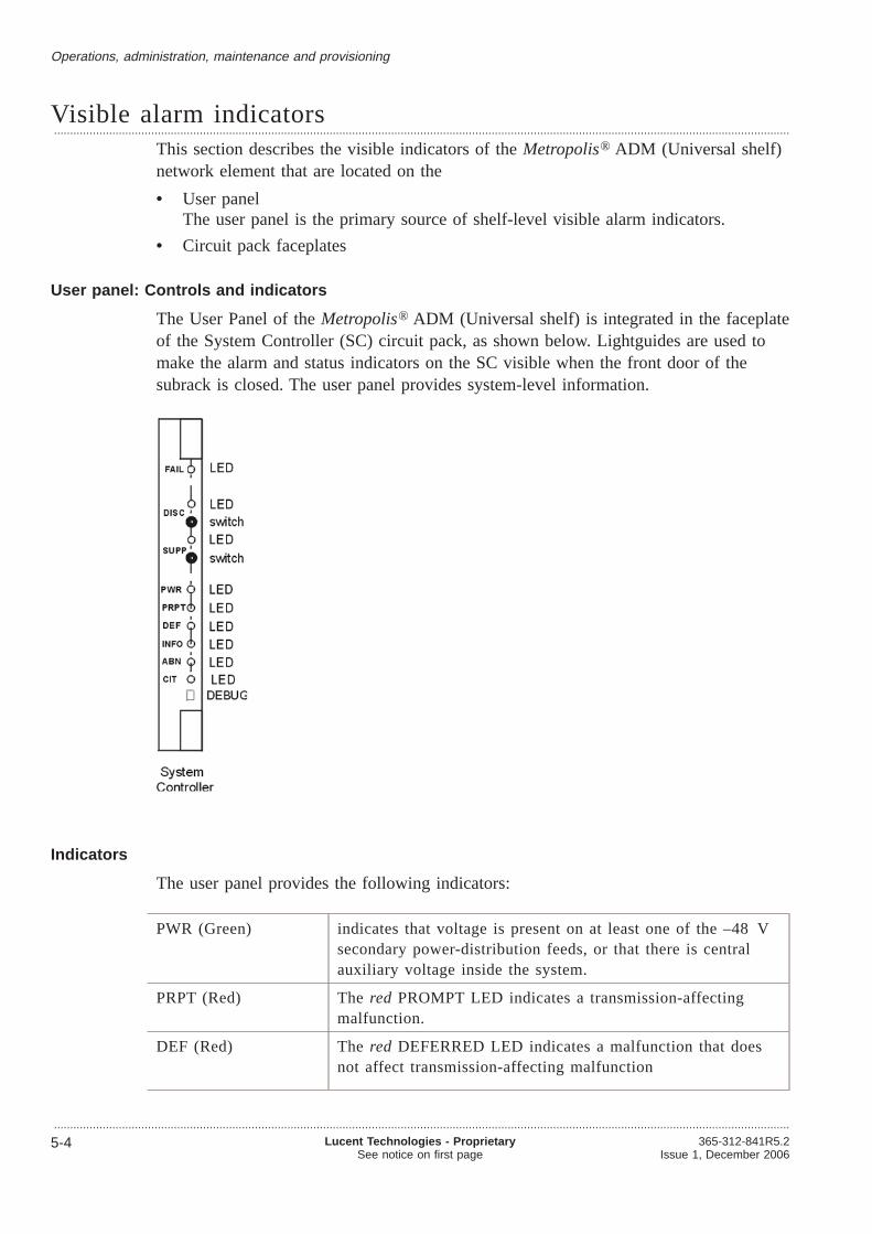
Visible alarm indicators...................................................................................................................................................................................................................................
This section describes the visible indicators of theMetropolis® ADM (Universal shelf)network element that are located on the
• User panelThe user panel is the primary source of shelf-level visible alarm indicators.
• Circuit pack faceplates
User panel: Controls and indicators
The User Panel of theMetropolis® ADM (Universal shelf) is integrated in the faceplateof the System Controller (SC) circuit pack, as shown below. Lightguides are used tomake the alarm and status indicators on the SC visible when the front door of thesubrack is closed. The user panel provides system-level information.
Indicators
The user panel provides the following indicators:
PWR (Green) indicates that voltage is present on at least one of the –48 Vsecondary power-distribution feeds, or that there is centralauxiliary voltage inside the system.
PRPT (Red) Thered PROMPT LED indicates a transmission-affectingmalfunction.
DEF (Red) Thered DEFERRED LED indicates a malfunction that doesnot affect transmission-affecting malfunction
Operations, administration, maintenance and provisioning
...................................................................................................................................................................................................................................
5-4 Lucent Technologies - ProprietarySee notice on first page
365-312-841R5.2Issue 1, December 2006

INFO (Yellow) indicates a failure that is not located within the terminal. Ifonly the INFO indicator is lit, no immediate maintenanceaction is required. The user can provision the alarm severities(PROMPT, DEFERRED and INFO) of the fault messages.
ABN (Yellow) indicates the existence of abnormal conditions in the networkelement, for example a protection lock-out, a forced switch, amanual switch, a protection line in use, an alarmdisconnected, or a failed installation self-test.
SUPP (Yellow) indicates that the SUPPRESS key has been activated while anactive office alarm condition exists.
DISC (Yellow) indicates that the DISC (disconnect) key has been activated,which means that office alarms are disconnected.
CIT (Yellow) indicates when the ITM-CIT must be used to obtain moredetailed information about system status.
Controls and connectors
Two manual controls (switches) and one connector are mounted on the SC faceplate.The functions are as follows:
• SUPP SWITCH: An alarm that is shown on the user panel can be suppressed bypressing the SUPPRESS SWITCH push-button, which will light up the SUPPRESSLED. If another alarm of the same class occurs, it will now be noticed.
• DISC SWITCH: Pressing the DISC SWITCH push-button inhibits the activation ofdisconnectable office alarms and lights up the DISC LED.
Circuit pack indicators
To supplement the user panel’s system-level view, each circuit pack has a red FAILLED on its faceplate (at the top of the faceplate).
• During normal fault-free operation, the LED is not lit.
• A continuously lit FAIL LED means that theMetropolis® ADM (Universal shelf)has isolated a failure to this circuit pack, or that the circuit pack has been insertedin a slot that cannot support or is not configured to support this type of pack.
Operations, administration, maintenance and provisioning Visible alarm indicators
....................................................................................................................................................................................................................................365-312-841R5.2Issue 1, December 2006
Lucent Technologies - ProprietarySee notice on first page
5-5

• An 1 Hz flashing FAIL LED shows the following:
– a flashing FAIL LED on an interface circuit pack indicates that an incomingsignal to that circuit pack has failed
– a flashing FAIL LED on the STM-16 core unit or STM-64 core unit indicatesan external timing reference failure. The green LED indicates the correctoperation of the timing and cross connect functions of the core unit.
– a flashing FAIL LED on the SC indicates loss of communication with themanagement system.
• a rapidly flashing FAIL LED on a circuit pack indicates that the primary boot code(a piece of software located in the nonvolatile memory of each circuit pack) isautomatically upgraded by the system. The primary boot upgrade happens duringupgrades but also if a pack with an older primary boot version (i.e.from sparestock) is inserted to the system.
Operations, administration, maintenance and provisioning Visible alarm indicators
....................................................................................................................................................................................................................................
5-6 Lucent Technologies - ProprietarySee notice on first page
365-312-841R5.2Issue 1, December 2006

ITM-CIT...................................................................................................................................................................................................................................
Metropolis® ADM (Universal shelf) is shipped with software for aWindows® 2000 orWindows® XP-based GUI that runs on a customer-furnished desktop or laptopcomputer. The GUI provides
• Control of operations, administration, maintenance and provisioning activities
• Security features to prevent unauthorized access
Definition
ITM CIT is a PC-based GUI software handling theMetropolis® ADM (Universal shelf)network elements one-by-one. It provides pull-down menus. It offers a unified set offeatures for provisioning, testing, and reporting. The ITM CIT is necessary to installand accept the system.
PC requirements
For the ITM-CIT a personal computer is necessary which fulfils the followingminimum requirements:
• Pentium® processor with 450 MHz or higher
• 128 MB RAM or higher
• Keyboard
• Mouse
• 300 MB of free hard-disk drive space
• CD-ROM drive
• SVGA monitor set to 1024x768 resolution or greater, 16 million colorsrecommended
• RS-232 communication port (serial asynchronous port)
• Windows XP® or Windows® 2000 operating system
• ITM-CIT connector (F-interface) cable (one end RS-232 and the other end RJ-45modular jack).
The performance can be enhanced by using a higher performance personal computer.Independent of the requirements listed above the minimum requirements of theoperating system must be fulfilled.
ITM CIT access
Metropolis® ADM (Universal shelf) supports local and remote access using a ITM CIT.Remote access uses the DCC (data communications channel) or an external WANconnected to aMetropolis® ADM (Universal shelf) LAN port.
Operations, administration, maintenance and provisioning
...................................................................................................................................................................................................................................365-312-841R5.2Issue 1, December 2006
Lucent Technologies - ProprietarySee notice on first page
5-7

Security function
Metropolis® ADM (Universal shelf) provides a security function to protect againstunauthorized access to the ITM-CIT system functions (such as provisioning). Securityis controlled through logins, passwords, and authorization levels for the systemfunctions.
Maintenance and administrative activities
The ITM CIT provides detailed information and system control of the followingspecialized local/remote maintenance and administrative activities:
• provisioning
• cross-connection assignments
• protection switching
• displaying performance-monitoring data
• fault management (alarms lists, etc.)
• polling inventory data of the NE
• software download to the NE
• loopback operation and testing
• reporting.
Operations, administration, maintenance and provisioning ITM-CIT
....................................................................................................................................................................................................................................
5-8 Lucent Technologies - ProprietarySee notice on first page
365-312-841R5.2Issue 1, December 2006

Operations interfaces...................................................................................................................................................................................................................................
Metropolis® ADM (Universal shelf) supports the following operations interfaces
• Rack top alarm indicators
• Station alarm interface
• Miscellaneous discrete interfaces
• Network management interfaces
• Data communications channels (DCC).
These features enable maintenance tasks (i.e., replacement of circuit packs ) to beperformed without an ITM-CIT (Craft Interface Terminal) or external test equipment.The second maintenance tier uses the ITM-CIT to retrieve detailed reports about alarmsand status, and about system configuration for local terminals.
Rack top alarm indicators
One red and one yellow indicator are present in top of the rack to signal a “prompt” ora “deferred” alarm respectively in one of the systems in the rack. The lamps arecontrolled from the “bay-top alarm outputs”.
Station alarm interface
The station alarm interface offers a number of hard contacts which can be used toextend the alarm signals from theMetropolis® ADM (Universal shelf) system into thestation alarm scheme. These contacts can be divided in four groups:
• Bay-top alarms (two outputs: prompt and deferred, not disconnectable)
• End-of-suite alarms (two outputs: prompt and deferred, disconnectable)
• Station alarms (two outputs: prompt and deferred, either disconnectable ornon-disconnectable)
• Miscellaneous maintenance information (three outputs: suppressed alarms present,disconnect function activated and main-controller removed).
Programmable station alarm raise/clear delay
The delay between the generation of the station alarm cause and the start of the actualstation-alarm and likewise the delay between the disappearing of the station-alarmcause and the clearing of the station-alarm is programmable. These two parameters areglobal for the system and can range between 0 and 60 seconds in 1 second increments.
Miscellaneous discrete interfaces
The miscellaneous discrete interface allows an operations system to control andmonitor equipment that is co-located with theMetropolis® ADM (Universal shelf)system through a series of input (MDI) and output (MDO) contact closures.
Eight miscellaneous-discrete inputs can monitor such conditions as open doors, hightemperature or high humidity, and four miscellaneous discrete control output labels canbe associated to alarms.
Operations, administration, maintenance and provisioning
...................................................................................................................................................................................................................................365-312-841R5.2Issue 1, December 2006
Lucent Technologies - ProprietarySee notice on first page
5-9

The status of the miscellaneous discrete environmental inputs is reported to thenetwork element management system. It is possible to activate these miscellaneous-discrete control outputs from the network element management system when thesystem reports an alarm condition. Miscellaneous-discretes are provided to the userthrough a connector at the MIO-L.
Network management interfaces
There are three network management interfaces:
• Q-LAN interfaces:The Q-LAN interfaces enable network-oriented communication between theMetropolis® ADM (Universal shelf) and the OMS. This is the standardizedinterface to Lucent Technologies management solutions.10 Base-T interfaces for Q-LAN are used on the miscellaneuos I/O area (MIO-L).
• CIT-F (Craft Interface Terminal) Interfaces:There is a RJ-45 interface on the miscellaneuos I/O area (MIO-L). The electricalcharacteristics of the CIT-F port comply with V.10.
• H-LAN (Hybrid LAN): 10/100 BASE-T LAN for future use.
Remote login/single ended operations/NSAP addresses (programmable)
The interfaces for the CIT-F (F-interface) provide the facility to log onto the localMetropolis® ADM (Universal shelf). Via the ITM-CIT a remote login is also possibleto otherMetropolis® ADM (Universal shelf) systems or to aMetropolis® ADM(Compact shelf) etc.
The OMS can perform control and provisioning tasks remotely.
The NSAP address is programmable to enable compatibility with the NSAP addressesof existing products like ISM, SLM, PHASE,WaveStar® ADM 16/1 etc. This willallow DCC interworking with other kinds of equipment.
Data communications channel (DCC)
This network operations capability uses the data communication channel (DCC) bytesof the SDH section (MSOH, D4 D12 and RSOH, D1 D3) . Management interfacedialogs and operations interface messages travel in these DCC bytes on each STM-Ninterface (N = 1, 4, 16, or 64).
The Metropolis® ADM (Universal shelf) supports at most 32 tributary and line DCCchannels simultaneously (counting RS-DCC and MS-DCC separately), whilemaintaining an acceptable throughput of management traffic.
Operations, administration, maintenance and provisioning Operations interfaces
....................................................................................................................................................................................................................................
5-10 Lucent Technologies - ProprietarySee notice on first page
365-312-841R5.2Issue 1, December 2006

Administration
Overview...................................................................................................................................................................................................................................
Purpose
The system management function for the administration ofMetropolis® ADM(Universal shelf) is operator administrated.
Security
The Metropolis® ADM (Universal shelf) provides for secure system access by meansof a two-tier security mechanism.
Contents
Security 5-12
NE administration concept 5-13
Operations, administration, maintenance and provisioning
...................................................................................................................................................................................................................................365-312-841R5.2Issue 1, December 2006
Lucent Technologies - ProprietarySee notice on first page
5-11

Security...................................................................................................................................................................................................................................
This section describes the various security features that theMetropolis® ADM(Universal shelf) provides to monitor and control access to the system.
User login security
The Optical Management System OMS provide security protection againstunauthorized access to the network element functions (for example provisioning). Thisfeature controls access to the system per user and includes:
• Login ID and password assignment: The user has to enter a valid Login ID andpassword to access the system
• User authorization levels: Provides three levels of access on a per session basis:
– Administrator: The Administrator is authorized to perform system controlactivities. These include starting and stopping management of the transmissionnetwork. Only this user can administer other users of the OMS application. Inaddition, backups can be created or restored by this user.
– Operator: The Operator is authorized to perform all retrieval and operatecommands that are not service-affected and do not change the systemconfiguration
– Supervisor: The Supervisor is authorized to perform all retrieval, provisioningand operate commands whether or not they are service affecting, with theexception of provisioning of security data and software downloads.
Login and password aging
The following aging processes provide additional means of monitoring and controllingaccess to the system:
• Login aging deletes individual logins if they remain unused for a pre-set number ofdays or on a particular date (for example, a visitor’s login or a login for temporaryaccess during installation)
• Password aging requires users to change passwords periodically.
Operations, administration, maintenance and provisioning
...................................................................................................................................................................................................................................
5-12 Lucent Technologies - ProprietarySee notice on first page
365-312-841R5.2Issue 1, December 2006

NE administration concept...................................................................................................................................................................................................................................
Target Identifier (TID)
It is possible to enter strings to be stored in theMetropolis® ADM (Universal shelf)denoting the target identifier (TID) of the NE.
Version recognition
The system provides automatic version recognition for all hardware and softwareinstalled on the system. The system can report the type, version and serial number ofthe circuit pack that is installed in each slot. Each circuit pack identification code isstored on the circuit pack itself and can be accessed by the system controller.
Inventory control
During normal operation, it is at any time possible to obtain (through the CIT or OMS)an inventory list with information on type, version and slot occupation of each systempart (these include units, backplane, I/O modules and converter boxes). Alsoinformation regarding the current and fallback software can be obtained.
Each field-replaceable unit is labeled in such a way that information needed to installproper units in the proper slot is contained on that label. The label also contains aserial (production) number.
Software upgrades
The Metropolis® ADM (Universal shelf) can easily be upgraded and reconfigured tosupport new services or to incorporate feature enhancements by downloading a newsoftware generic via the appropriate (F/Q) operations interface. Service is not normallyinterrupted by downloading and replacing software generics
The Metropolis® ADM (Universal shelf) stores two images of the software, the activeimage and the fall-back image. These images may be different. In an upgradeprocedure, the new software release is down-loaded in the fall-back memory area to beactivated by a special command.
Operations, administration, maintenance and provisioning
...................................................................................................................................................................................................................................365-312-841R5.2Issue 1, December 2006
Lucent Technologies - ProprietarySee notice on first page
5-13

Maintenance
Overview...................................................................................................................................................................................................................................
Purpose
This section introduces the maintenance features available in theMetropolis® ADM(Universal shelf).
Definition
Maintenance is the system’s capability to continuously monitor its equipment and thesignals that it carries in order to notify the user of any current or potential problems.This enables the user to take appropriate proactive (preventive) or reactive (corrective)action.
The maintenance applications are based on ITU-T recommendations M.2101.1, M.2110and M.2120 and are used for “Bringing Into Service (BIS)” and other initial testingprocedures and localization/monitoring of under-performing parts of an end-to-endpath.
Contents
Maintenance signals 5-15
Loopbacks and tests 5-19
Protection and redundancy 5-22
Performance monitoring 5-24
Reports 5-26
Orderwire 5-29
Operations, administration, maintenance and provisioning
...................................................................................................................................................................................................................................
5-14 Lucent Technologies - ProprietarySee notice on first page
365-312-841R5.2Issue 1, December 2006

Maintenance signals...................................................................................................................................................................................................................................
This section describes the maintenance signals available inMetropolis® ADM(Universal shelf).
Definition
The system maintenance signals notify downstream equipment that a failure has beendetected and alarmed by upstream equipment and notify upstream equipment to initiatetrunk conditioning due to a failure that has been detected downstream. These alarmsignals include Alarm Indication Signals (AIS), Far End Receive Failure ((MS-)RDI)signals, and UNEQuipped signals (UNEQ).
Alarms and status reports
The system provides a report that lists all active alarm and status conditions. Thisreport is made available to the network management system on demand. The identityof the condition is included in the report along with a time stamp that indicate whenthe condition was detected. There is an option to display specified subsets of alarmconditions.
Enable/disable autonomous alarm forwarding to the OMS
The Metropolis® ADM (Universal shelf) provides the option to inhibit, temporarily, theforwarding of autonomously generated alarms from the NE to the OMS. To restart theor to restart again the autonomous forwarding of alarms an enable command has to beissued by the user.
Programmable severity per fault-type per location instance
For each fault-type it is possible to provision the associated severity (values: “prompt”,“deferred” or “info”), individually for each location (e.g. port, TTP, CTP or unit)capable of generating this fault-type. It is possible to change the severity associatedwith a certain fault-type globally for all location instances with a single command. Themaximum amount of severity instances is 1000.
Element management and remote operations interfaces
Before it can begin providing services, theMetropolis® ADM (Universal shelf)requires a large amount of provisioning data. This data will be loaded upon installationin non-volatile memory but needs a reliable backup to support repair and maintenanceprocedures. It is therefore assumed that the equipment is connected to a back-updatabase either via a local port or via the embedded operations channels.
The Metropolis® ADM (Universal shelf) can be connected to a co-located OMS via theQ-LAN. At station level and besides local or remote network-management facilities, aCraft Interface Terminal (ITM-CIT) can be used to carry out local managementfunctions.
Operations, administration, maintenance and provisioning
...................................................................................................................................................................................................................................365-312-841R5.2Issue 1, December 2006
Lucent Technologies - ProprietarySee notice on first page
5-15

Fault detection, isolation and reporting
When a fault is detected, theMetropolis® ADM (Universal shelf) employs anautomatic diagnostics to isolate the failed circuit pack or signal. Failures are reportedto local maintenance personnel and operations systems so that repair decisions can bemade. If desired, operations system personnel and local maintenance personnel can usethe ITM-CIT to gain more detailed information on the fault condition.
Maintenance history report
A maintenance-history report past alarms, status, protection switching, and craft ormanagement events is provided and this report is made available to the networkmanagement system on demand. This summary contains a time stamps that indicateswhen each condition was detected and cleared, or when a command was entered.
The Metropolis® ADM (Universal shelf) system also automatically and autonomouslyreports all detected alarm and status conditions through the office alarm relays, the userpanel, equipment LEDs, and message based operations systems.
SDH non-intrusive monitor failure reports
The VC-4(-4c/16c), VC-3, VC-12 and VC-11 (in TU-12) Non-Intrusive Monitors(NIM’s) can be in Monitored (MON) or Non-Monitored (NMON) mode. If a NIM ispart of an SNC/N scheme it is put in MON mode. If a NIM is not part of an SNC/Nscheme it is normally NMON, but it can be put in MON mode, provided the necessaryconfiguration data is provided.
In MON mode the cTIM, cUNEQ, and cDEG alarms are forwarded to the OMS andCIT and optionally cRDI and cSSF.
Performance LAN interface
For each LAN interface the performance of the incoming and outgoing LAN streams(3 × 8 counters) as well as the incoming and outgoing WAN streams (up to 3 × 8)counters are monitored for (refer to“Ethernet performance monitoring counters”(p. 2-96)):
• incoming packets dropped due to error
• bytes sent
• bytes received.
LAN related alarms
The Metropolis® ADM (Universal shelf) reports LAN related data and switchingalarms. Loss of Signal (for ports in monitored state) or unexpected presence of a signal(for ports in non-monitored state) at the LAN interfaces are alarmed per LANinterface.
Operations, administration, maintenance and provisioning Maintenance signals
....................................................................................................................................................................................................................................
5-16 Lucent Technologies - ProprietarySee notice on first page
365-312-841R5.2Issue 1, December 2006

Quality of service application
The Quality of Service (QoS) application is based on ITU-T Recommendations G.826and G.827. In contrast to the maintenance application, the QoS application requires aperformance assessment of the bidirectional path over longer periods.
To support the QoS application in the network element, theMetropolis® ADM(Universal shelf) logs the current and most recent 24 hour periods of the UAP,UAP-count (number of unavailable periods) and UAS for the bidirectional connection,whereby the bidirectional connection is considered unavailable as soon as one of thedirections is unavailable.
In addition, for each monitoring point the BBE, ES and SES counts are reported fordirections individually. So there are nine parameters altogether per bidirectionalmonitoring point.
Note that all six BBE, ES and SES counters are inhibited as soon as the bidirectionalconnection is unavailable. This is why the bidirectional counts may differ from theuni-directional counts, even if they are for the same path and the same monitoringinterval.
Bidirectional performance monitoring comes in two flavors:
• in “end-points” or TTPs
• in “mid-points” or CTPs
The following monitoring points in theMetropolis® ADM (Universal shelf) supportbi-directional PM:
• VC-12 TTPs, VC-3 TTPs and VC-4 TTPs and
• VC-12 CTPs, VC-3 CTPs, VC-4 CTPs, VC-4-4c CTPs and VC-4–16c CTPs.
Bidirectional performance reports in end-points are based on the near-end and far-end(RDI) information that is received on the incoming signal. Bidirectional performancereports in midpoints are based on the far-end information that is contained in theincoming signal in both directions of transmission.
Severity settings for alarms on each termination-point instance
Since different clients pay for different levels of Quality of Service (QoS), the priorityand the time to repair can differ for different paths. By setting a higher severity for thealarms on paths that require a high QoS, than for the paths that require a low QoS, theQoS performance can be improved. In the subsection on Performance Monitoring theconcept of quality of service is explained in more detail.
Support for a multiplex-section trace identifier (JO byte)
The user can provide a multiplex section trace identifier on all STM-N (N = 1, 4, 16,64) outputs of theMetropolis® ADM (Universal shelf) via the OMS or ITM-CIT. Inthe receive direction an expected value for this trace identifier can be provided. In thecase of a mismatch a TIM (Trace Identifier Mismatch) alarm is generated andconsequent actions are invoked. The TIM detection mechanism can be disabled perinterface.
Operations, administration, maintenance and provisioning Maintenance signals
....................................................................................................................................................................................................................................365-312-841R5.2Issue 1, December 2006
Lucent Technologies - ProprietarySee notice on first page
5-17

Recovery from database failures
If the Metropolis® ADM (Universal shelf) detects that its MIB is empty or corrupted, amechanism is in place to automaically start a MIB download from the OMS.
If the serial number in the NE database (located on the controller unit) does not matchthe (unique) serial number of the NE on the backplane, the NE will inform theoperator. This allows the operator to make a choice on either to accept the database ornot.
Operations, administration, maintenance and provisioning Maintenance signals
....................................................................................................................................................................................................................................
5-18 Lucent Technologies - ProprietarySee notice on first page
365-312-841R5.2Issue 1, December 2006

Loopbacks and tests...................................................................................................................................................................................................................................
This section describes the loopbacks and tests that theMetropolis® ADM (Universalshelf) performs.
Loopback definition
A loopback is a troubleshooting test in which a signal is transmitted through a port unitto a set destination and then returned to the originating port unit. The transmitted andreceived signals are measured and evaluated by the user to ensure that the receivedsignal is accurate and complete when compared to the originating signal.
Loopbacks can be distinquished in loop-backs for incoming and outgoing signals.
These loopbacks can be setup per input from the ITM-CIT or OMS.
Loopbacks on incoming STM-64 signals
Within the Metropolis® ADM (Universal shelf) temporary loopbacks can be set on thecorresponding line input. The looped back input is routed directly to its correspondingoutput, passing through as few system parts as possible and leaving the signal formatintact.
The loopbacks are “non-transparent”, i.e. the signal is replaced by AU-AIS signalindication downstream from the loopback point.
Simultaneous loopback and 1+1 MSP on the same tributary port is permitted.
Loopbacks on incoming STM-16 signals
Within the Metropolis® ADM (Universal shelf) temporary loopbacks can be set on anSTM-16 system input, the incoming signal is looped back to the corresponding systemoutput. The complete STM-16 is looped back, while the forwarded signal is replacedby AU-AIS.
The loopbacks are “non-transparent”, i.e. the signal is replaced by AU-AIS signalindication downstream from the loopback point.
Simultaneous loopback and 1+1 MSP on the same tributary port is permitted.
Loopbacks on incoming E1, E3, DS1,DS3, and STM-1e signals
Within the Metropolis® ADM (Universal shelf) temporary loopbacks can be set on thecorresponding tributary input or line input. The looped back input is routed directly toits corresponding output, passing through as few system parts as possible and leavingthe signal format intact.
The loopbacks are “non-transparent”, i.e. the signal is replaced by AIS signal indicationdownstream from the loopback point.
Specifically for E1 or DS1 loopbacks, there is a limitation that at most one incomingloopback per E1 unit can be active at any time.
Operations, administration, maintenance and provisioning
...................................................................................................................................................................................................................................365-312-841R5.2Issue 1, December 2006
Lucent Technologies - ProprietarySee notice on first page
5-19

Loopbacks on incoming STM-1o signals
Within the Metropolis® ADM (Universal shelf) temporary loopbacks can be set on theSTM-1o tributary unit. The incoming signal is looped back to the correspondingsystem output.
The loopbacks are “non-transparent”, i.e. the signal is replaced by AIS signal indicationdownstream from the loopback point.
Note that simultaneous loopback and 1+1 MSP on the same tributary port is permitted
Loopbacks on incoming STM-4 signals
Within the Metropolis® ADM (Universal shelf) temporary loopbacks can be set on anSTM-4 system input, i.e. on the STM-4 tributary unit. The incoming signal is loopedback to the corresponding system output. The complete STM-4 is looped back, whilethe forwarded signal is replaced by AIS.
The loopbacks are “non-transparent”, i.e. the signal is replaced by AIS signal indicationdownstream from the loopback point.
Note that simultaneous loopback and 1+1 MSP on the same tributary port is permitted
Loopbacks on outgoing STM-64 signals
Within the Metropolis® ADM (Universal shelf) temporary loopbacks can be set on thecorresponding tributary output or line ouput. The outgoing signal is looped back to itscorresponding (backplane) input, passing though as many system parts as possible.
The loopbacks are “non-transparent”, i.e. the signal is replaced by MS-AIS signaldownstream from the loopback point.
Important! This feature is only supported by LKA49, LKA29, LKA28, LKA281and LKA350.
Loopbacks on outgoing STM-16 signals
Within the Metropolis® ADM (Universal shelf) temporary loopbacks can be set onSTM-16 system output, the outgoing signal is looped back at the VC-4 level to thecorresponding (backplane) inputs. The loopback is″″ non-transparent″″ : Theforwarded signal is replaced by MS-AIS.
Simultaneous loopback and 1+1 MSP on the same tributary port is permitted.
Loopbacks on outgoing E1, E3, DS1, DS3 and STM-1e signals
Within the Metropolis® ADM (Universal shelf) temporary loopbacks can be set on thecorresponding tributary output or line ouput. The outgoing signal is looped back to itscorresponding (backplane) input, passing though as many system parts as possible.
The loopbacks are “non-transparent”, i.e. the signal is replaced by AIS signaldownstream from the loopback point.
Specifically for E1 loopbacks, there is a limitation that at most one outgoing loopbackper E1 unit can be active at any time.
Operations, administration, maintenance and provisioning Loopbacks and tests
....................................................................................................................................................................................................................................
5-20 Lucent Technologies - ProprietarySee notice on first page
365-312-841R5.2Issue 1, December 2006

Loopbacks on outgoing STM-1 optical signals
Within the Metropolis® ADM (Universal shelf) temporary loopbacks can be set onSTM-1 system output, i.e. on the STM-1o tributary unit. The outgoing signal is loopedback at the VC-4 level to the corresponding (backplane) input. The loopback is“non-transparent”, i.e. the forwarded signal is replaced by MS-AIS for STM-1otributary unit.
Simultaneous loopback and 1+1 MSP on the same tributary port is permitted.
Loopbacks on outgoing STM-4 optical signals
Within the Metropolis® ADM (Universal shelf) temporary loopbacks can be set onSTM-4 system output, i.e. on the STM-4 tributary unit the outgoing signal is loopedback at the VC-4 level to the corresponding (backplane) inputs. The loopback is“non-transparent”; the forwarded signal is squelched.
Simultaneous loopback and 1+1 MSP on the same tributary port is permitted.
Software-initiated loopbacks
Metropolis® ADM (Universal shelf) can perform software-initiated facility loopbackswithin the port units (near-end or in-loopbacks and far-end or out-loopbacks), as wellas software-initiated cross-connect loopbacks. Active loopbacks are indicated by theabnormal (ABN) LED on the user panel.
Local system test
The local system test and diagnostics are executed on demand from the CIT to verifycorrect operation of those parts of the system that can be covered by test signals.Additional diagnostic tests are performed for fault isolation.
LED test
An LED test can be performed on demand from a CIT to verify whether all LEDs onthe system still function. This operation can not be initiated from the OMS.
Self-diagnostics (in service)
The Metropolis® ADM (Universal shelf) runs audits and diagnostics to monitor itshealth. These self-diagnostics don’t have any effect on the performance of the system.
The system will automatically run diagnostic tests:
• Processor system:
– Power-on tests: memory write/read tests (RAM), Checksum tests (ROM,FLASH). These tests are only performed when a unit is inserted in the system
– Run time tests: non-volatile memory checksum tests, watchdog. These tests areperformed continuously.
• Transmission system: such as parity checks at transmission devices (ASICs), databus supervision, power supply supervision at plug-in units, internal synchronizationsupervision. These are monitored continuously.
Operations, administration, maintenance and provisioning Loopbacks and tests
....................................................................................................................................................................................................................................365-312-841R5.2Issue 1, December 2006
Lucent Technologies - ProprietarySee notice on first page
5-21

Protection and redundancy...................................................................................................................................................................................................................................
Overview
The following specifications apply to theMetropolis® ADM (Universal shelf) withregard to protection and redundancy.
Equipment protection
1:N equipment protection on E1/DS1 (N = max. 4)
1+1 equipment protection on the E3/DS3 and STM-1e units.
1+1 equipment protection on the STM-16 and STM-64 core units
• Power
• Timing
• Cross-connection
MSP
STM-1, STM-4 and STM-16, and STM-64 optical interface circuit packs support 1+1MSP according to G.841 annex B, G.841 Clause 7.1 and ETSI 300417–3–1.
MS-SPRing
MS-SPRing is used in two fiber ring add/drop applications.
Selective MS-SPRing in two fiber add/drop ring applications. The VC-4 (-4c,-16c)s inthe ring can be protected by MS-SPRing algorithm according to G.841 and ETS300417.
The customer has the option to determine for each VC-4(-4c,-16c) individually,whether or not it participates in the MS-SPRing scheme. If an individual VC-4(-4c,-16c) does not participate then it can be either VC-4(-4c,-16c) SNC protected ornot protected at all.
The protection scheme provides also “extra traffic” on STM-16 and STM-64 interfacesin the MS-SPRing configuration. Preemptible Protection Access (PPA) or extra trafficis a feature using the protection capacity of a MS-SPRing in order to carry some extra“low priority” traffic.
SNCP/N
SubNetwork Connection Protection (SNCP) on VC-12, VC-3, VC-4, VC-4-4c orVC-4-16c signal level according to G.841/Clause 8. The SNCP is based onnon-intrusive monitoring of the sub-network connection (SNC/N).
SNCP protection switching can be configured revertive or non-revertive. Whenrevertive switching is configured, a wait-to-restore time can be defined. The defaultconfiguration is non-revertive.
Operations, administration, maintenance and provisioning
...................................................................................................................................................................................................................................
5-22 Lucent Technologies - ProprietarySee notice on first page
365-312-841R5.2Issue 1, December 2006

During the set up of non-revertive SNCP schemes, the user can assign whichconnection of the protection pair will become the working one.
Other specifications
The following specifications apply also to theMetropolis® ADM (Universal shelf) too:
• cascading of protection schemes in one network element
• maximum of 50 ms switching time for all protection mechanisms.
• programmable hold-off timers.
Operations, administration, maintenance and provisioning Protection and redundancy
....................................................................................................................................................................................................................................365-312-841R5.2Issue 1, December 2006
Lucent Technologies - ProprietarySee notice on first page
5-23

Performance monitoring...................................................................................................................................................................................................................................
Performance Monitoring provides the user with the facility to systematically track thequality of a particular transport entity. This is done by means of continuous collectionand analysis of the data derived from defined measurement points.
Basic measurement parameters
To support these applications theMetropolis® ADM (Universal shelf) provides, foreach performance-monitoring process, the current 15 minute and current 24 hourcounts of the
• BBE (Background Block Errors)
• ES (Errored Seconds)
• SES (Severely Errored Seconds)
• UAS (UnAvailable Seconds) and
• UAP (UnAvailable Period).
Performance monitoring on the Gigabit Ethernet card
Ethernet performance monitoring in SDH network elements is kept as closely related toSDH performance monitoring as possible. This means that the concepts of binning andthresholding are completely reused. Refer to“Ethernet performance monitoringcounters” (p. 2-96).
There are two levels of Ethernet performance monitoring possible:
• monitoring per port
• monitoring per port per traffic class. This option monitors all packets of allcustomers that belong to a specific traffic class
The following list is an overview of the Ethernet performance parameters related to thetransmit direction. These parameters are presented in 15 minute and 24 hour reports.Thresholding is applicable for Ethernet parameter for:
• outgoing number of Mbytes (EONB)
• dropped frames - errors (EDFE)
• incoming number of Mbytes (EINB)
Enabling performance measurement points
Performance measurement points can be enabled via ITM-CIT or OMS. Please refer tothe Metropolis® ADM (Universal shelf) User Operations Guide.
Monitoring points
For maintenance applications theMetropolis® ADM (Universal shelf) supports thecounting, threshold monitoring and logging of all the parameters mentioned above forthe incoming traffic direction (or “unidirectional near-end” performance monitoring).
Operations, administration, maintenance and provisioning
...................................................................................................................................................................................................................................
5-24 Lucent Technologies - ProprietarySee notice on first page
365-312-841R5.2Issue 1, December 2006
Possible monitoring points are:
• VC-12, VC-3 and VC-4 Trail Terminations Points (TTPs)
• MS-1, MS-4, MS-16, RS-16, MS-64 and RS-64 termination points
• VC-12, VC-3, VC-4, VC-4-4c,VC-4-16c transit points or Connection TerminationPoints (CTPs).
Note that the unidirectional near-end performance monitoring indicates the performanceof the incoming signal between the source of the signal trail and the monitoring point.
The BBE, ES, SES, UAS and UAP parameters are derived from the errors in theincoming signal and are based on the B1, B2, B3 or V5 (bit 1,2) parity informationthat is part of the RSOH, MSOH or VC-POH. Periods of unavailable time are, alsobased on local defects or defects in the incoming signal. For the duration of a period ofunavailable time the BBE, ES and SES counters are inhibited.
Number of performance monitoring points
The Metropolis® ADM (Universal shelf) can support 1200 monitoring pointssimultaneously. These points can be randomly selected from all the possible TTPs andCTPs that are indicated above, where the “uni-directional near-end” and “bidirectional”applications are each counted seperately. Once a performance monitoring point isactivated the full set of performance parameters is supported.
Threshold report and reset threshold report
In addition the recent history of these parameters remains stored in the networkelement, namely the 16 most recent complete 15 minute counts and the 1 most recentcomplete 24 hour count. For all current-interval counters, thresholds can be set thatcontrol the forwarding of Threshold Report (TR) and Reset Threshold Report (RTR)information to the management system.
A TR is generated at the moment that the current count in a register crosses the “set”threshold level for the first time since the last RTR. An RTR is generated at the end ofthe first interval in which the current count remains below the “clear” threshold. So theTRs and RTRs are generated in an altemetely way.
In the period between a TR and an RTR the monitored part of the path is considered tobe degraded, while it is considered normal in the period between an RTR and a TR.The “set” and “clear” thresholds can be assigned by the user via the ITM-CIT or theOMS.
Unavailable periods
In addition to the above parameters, the 6 most recent UAPs (Unavailable Periods) arealso logged in the system. Each UAP is represented by two time stamps. The firstindicates the moment of entry into “unavailable time” and the second indicates themoment of entry into subsequent “available time”.
Operations, administration, maintenance and provisioning Performance monitoring
....................................................................................................................................................................................................................................365-312-841R5.2Issue 1, December 2006
Lucent Technologies - ProprietarySee notice on first page
5-25

Reports...................................................................................................................................................................................................................................
This topic contains information about the
• active alarms and status reports
• performance monitoring reports
• history reports
• report on circuit pack, slot, port and switch states
• version/equipment list
• synchronization reports
Active alarms and status
The Metropolis® ADM (Universal shelf) provides a report that is shows all the activealarm and status conditions. The local alarms and the status report are displayedautomatically on the local ITM-CIT immediately after log in or directly on the networkelement management system. The report shows the following alarm levels:
• PROMPT
• DEFERRED
• INFO
• NO REPORT.
The source address description of the alarm condition (for example controller failure,high-speed signal failure) is included in the report along with the date and time whenthe alarm was detected. The report also shows whether the alarm condition affectsoperations. There is also the option of displaying specified subsets of alarm conditionsby severity.
Provisionable reporting mode per fault-type per instance
For each fault-type the associated reporting mode (values: “reported” and“non-reported”) is provisionable, individually for each location (e.g. port, TTP, CTP orunit) capable of generating this fault-type. It is possible to change the reporting modeassociated with a certain fault-type globally for all location instances with a singlecommand. The maximum amount of “reported/non-reported” instances is 1000.
Date and time function
The Metropolis® ADM (Universal shelf) has a real time clock signal available that issynchronized with the management system. It can be set through the ITM-CIT orOMS. The clock is used to timestamp operations, maintenance and performancemonitoring events.
Operations, administration, maintenance and provisioning
...................................................................................................................................................................................................................................
5-26 Lucent Technologies - ProprietarySee notice on first page
365-312-841R5.2Issue 1, December 2006

Reporting of analog parameters
Upon user request, the ITM-CIT and OMS can report the values of the laser biascurrent and optical transmitted power (derived from the backface current) of anySTM-16 or STM-64 unit in the system. In addition, the value of the optical receivedpower is reported.
State
An on-demand report displays the equipment and the equipment status.
Equipment report indicates:
• equipment
• location
• circuit pack type
• version
• slot status (the slot status can be auto or equipped).
Equipment status indicates:
• equipment
• location
• circuit pack type
• port status (if applicable)
• service status (if applicable).
Support subsystem failure reports
Failure reports are generated for faults in support subsystems.
Possible support subsystems are:
• the power supply subsystem
• the timing subsystem
• the control subsystem and
• the temperature control subsystem.
Resolution of failure reports
The resolution of the failure reports is such that the operator can identify whether thefault is inside or outside the system. In both cases the operator will get enoughinformation to identify the next step in the fault correction process, e.g. replace a unit,change a configuration value, reconnect a cable, start a cable fault location process.
Version/equipment list
The version/equipment list is an on-demand report that lists the circuit pack versionand the software generic (if applicable). This report also lists all of the circuit packsthat are present.
Operations, administration, maintenance and provisioning Reports
....................................................................................................................................................................................................................................365-312-841R5.2Issue 1, December 2006
Lucent Technologies - ProprietarySee notice on first page
5-27

Synchronization report
The synchronization report is an on-demand report that lists the status of the systemsynchronization. This report lists all of the clock parameters that can be interrogated.
Fan unit alarm
One fan unit, a dust filter and a controlling unit, must be present in the subrack. A fanunit contains two fans for redundancy. The fan unit (fan tray) can be replaced from thesubrack at full operational conditions, without any service interruption or cablingrearrangements. This is needed for exchanging a failed fan unit.
The rotation speed of the fan unit is controlled by the fan controlling unit. This is tolower the noise level under low temperature conditions. The System Control unitmeasures the temperature in the subrack. The dust filter can be replaced or cleaned(both types are available) easily by the craft. Under normal conditions, the maintenanceinterval is at least 3 months depending on environmental dust loads. Proper cooling isstill ensured if one of the two fans is failing.
The fan unit has a red fault LED and reports:
• FAN unit failure (FANc EQF)
• FAN unit power failure (FANc PWR)
Operations, administration, maintenance and provisioning Reports
....................................................................................................................................................................................................................................
5-28 Lucent Technologies - ProprietarySee notice on first page
365-312-841R5.2Issue 1, December 2006

Orderwire...................................................................................................................................................................................................................................
This section provides information about orderwire.
Description
Engineering Orderwire (EOW) provides voice or data communications for maintenancepersonnel to perform facility maintenance.
User channels
The section overhead of all SDH interfaces and the VC-3/VC-4 path overhead containseveral bytes, for instance E and F bytes, that can be used to provide 64 kbit/soperations channels.
The Metropolis® ADM (Universal shelf) provides for a maximum of four transparent64 kbit/s channels that are selected from the following overhead bytes:
• E1 and E2 bytes: Channels from these bytes are mainly called Engineering OrderWire channels
• F1 bytes: Channels from these bytes are mainly called: user channels
Operations, administration, maintenance and provisioning
...................................................................................................................................................................................................................................365-312-841R5.2Issue 1, December 2006
Lucent Technologies - ProprietarySee notice on first page
5-29

Provisioning
Overview...................................................................................................................................................................................................................................
Purpose
The Metropolis® ADM (Universal shelf) system supports many system applications byits provisioning features. Provisioning parameters are set by software control. Theseparameters vary from one installation to the next, and a wide range of options orin-service changes can be provisioned locally or remotely with the aid of ITM-CIT orOMS.
Definition
Provisioning refers to assigning values to parameters used for specific functions bynetwork elements. The values of the provisioned parameters determine many operatingcharacteristics of a network element.
References
For more information about provisioning parameters and original values using theITM-CIT, refer to the Metropolis® ADM (Universal shelf) User Operations Guide.
Contents
Introduction 5-31
Operations, administration, maintenance and provisioning
...................................................................................................................................................................................................................................
5-30 Lucent Technologies - ProprietarySee notice on first page
365-312-841R5.2Issue 1, December 2006
Introduction...................................................................................................................................................................................................................................
Default provisioning
Installation provisioning is minimized with the aid of carefully chosen defaultvalues/parameters that are defined and maintained in the System Controller, and asimple command can be given to restore all default values. All provisioning data isstored in non-volatile memory to prevent data loss during power failures.
Circuit pack replacement provisioning
Replacement of a faulty circuit pack is simplified by the automatic provisioning of theoriginal values. The System Controller maintains a provisioning map of the entiresubrack, so when a transmission circuit pack or a core unit is replaced the SystemController automatically downloads values to the new circuit pack and initiates testingof the new circuit pack. If the System Controller itself is replaced, provisioning datafrom a backup database in OMS is automatically downloaded to the new SystemController’s non-volatile memory if that memory it is empty.
If the controller database is not empty but valid, the choice is offered betweendownloading and uploading.
Flexible circuit pack replacement
The system allows to exchange optical circuit packs and SFP’s against others of thesame bitrate, but with other wavelength or other haul without any need for changingthe traffic related configuration data, e.g. protection groups, links, synch., ... providedthe new pack supports the configuration (counter-example: exchanged pack had FEC,the new one not).
Provisioning reports
The provisioning report, which is made available to the OMS on demand, contains thecurrent values of all provisionable parameters.
Provisionable SS bits
This feature allows users to provision the value of bits 5 and 6 (the SS bits) which aretransmitted in the first H1 pointer byte of a VC signal. Present SONET (Telcordia) andSDH (ITU-T) standards require the receiving equipment to ignore these bits, but someolder embedded SONET and SDH equipment may not ignore these bits.
In the source direction, provisioning the SS bits to “10” (overwrite disabled) allowsinterworking with older embedded SDH equipment.
In the source direction, provisioning the SS bits to “00” (overwrite enabled) allowsinterworking with older embedded SONET equipment.
In the sink direction, the incoming SS bits are ignored.
The SS bits are provisionable per port basis.
Operations, administration, maintenance and provisioning
...................................................................................................................................................................................................................................365-312-841R5.2Issue 1, December 2006
Lucent Technologies - ProprietarySee notice on first page
5-31
Provisioning of slots
Via the ITM-CIT or OMS, each slot or position in the system which can hold a plug-inunit, I/O module or converter box can be put in the UNASSIGNED, ASSIGNED orAUTO state. When a position in the system is put in the AUTO or ASSIGNED state,an identifier (type, version) of the entity to be inserted needs to be entered as well.
Depending on the configuration, the NE maintains a list of allowed (compatible) unitsfor each position and keeps track of restrictions that may apply on the allowed statesfor some (mandatory) positions.
• if a slot or position is put in the UNASSIGNED state, a configuration alarm will begenerated as soon as a unit is plugged in; no service is provided on the unit and noother alarms are generated
• if a slot or position is put in the ASSIGNED state a configuration alarm will begenerated as soon as the unit is removed or an incompatible unit is inserted
• if a slot or position is put in the AUTO state, no configuration alarms will begenerated as long as the position remains unequipped. As soon as the position isequipped the slot state will automatically change to ASSIGNED.
Provisioning port monitoring modes
Port monitoring modes represent the monitoring state for each port in the system atany given time. Each port monitoring mode has its own characteristics for signalfailure alarms and PM (Performance Monitoring) data collection. Transitions betweenmodes occur due to events such as applying a good signal orWaveStar® Managementcommands. The detection of a fault does not affect the state of the port monitoringmode.
Port modes
The port modes in theMetropolis® ADM (Universal shelf) are:
• Automatic (AUTO): AUTO refers to a port that is available for automaticprovisioning. A port changes from the AUTO mode to the MON mode if a goodsignal is detected. The original port monitoring mode value is AUTO. When theport monitoring mode is AUTO, the port is not alarmed
• Monitored (MON): MON refers to a port that is fully monitored and alarmed
• Not Monitored (NMON): NMON refers to a port that is not monitored and doesnot change to the MON state even if a good signal is detected. Any port modes canbe user-provisioned independently to the NMON state at any time, regardless of theauto-provisioned mode of the terminating interface slot. This port mode is used tosuppress alarms.A port that is not monitored will not raise any alarms. If there still is a signalpresent on the not monitored port, it is possible to receive a Not Expected InputSignal (NES) alarm. The alarm status of NES must then be provisioned Reported.
The figure below shows the possible port modes and the transitions between them.
Operations, administration, maintenance and provisioning Introduction
....................................................................................................................................................................................................................................
5-32 Lucent Technologies - ProprietarySee notice on first page
365-312-841R5.2Issue 1, December 2006

Provisioning of Trail Termination Point modes
To prevent alarms from being raised and failures from being reported during trailprovisioning, trail termination functions can enable and disable fault cause declarations.
Modes
The Trail Termination Point modes in theMetropolis® ADM (Universal shelf) are:
• Monitored (MON): MON refers to a tTrail Termination Point that is fullymonitored and alarmed
• Not Monitored (NMON): NMON refers to a Trail Termination Point that is notmonitored. This trail termination point mode is used to suppress alarms.
The figure below shows the possible trail termination point modes and the transitionsbetween them.
IS-IS level 2
The Metropolis® ADM (Universal shelf) can act as a network layer (OSI protocol stacklayer 3) relay system in the Data Communication Network (DCN), which can beinterconnected via LAN (including TMN Q-interfaces) and DCC channels.Management messages between the OMS and SDH network elements of any type inthe managed network can be routed via one or more connections includingMetropolis®
ADM (Universal shelf).
Operations, administration, maintenance and provisioning Introduction
....................................................................................................................................................................................................................................365-312-841R5.2Issue 1, December 2006
Lucent Technologies - ProprietarySee notice on first page
5-33

The nodes in this management information network can be organized in two levels:
• on level 1, each node can route messages to an other node in the same area
• on level 2, each gateway node of an area can route messages to an other gatewaynode in the same DCN.
OSI-Layer 3 functionality via the Q-LAN is implemented according to ISO-IEC-8648(General), ISO-IEC-8473 (CLNP), ISO-IEC-9542 (ES-IS) and ISO-IEC-10589 (IS-IS).
DCC-partition repair
Partition Repair provides a way to repair the intra-area routing function in spite ofIS-IS area partitioning. This is done by creating a path outside the area, between twoLevel-2 nodes (which are provisioned to be Partition Capable Level-2 nodes),belonging to distinct partitions of the same IS-IS area. Level-1 IS-IS/CLNP PDUs areencapsulated and transferred over that path. This is sometimes referred to aslevel1-tunneling.
Operations, administration, maintenance and provisioning Introduction
....................................................................................................................................................................................................................................
5-34 Lucent Technologies - ProprietarySee notice on first page
365-312-841R5.2Issue 1, December 2006

6 6System planning andengineering
Overview...................................................................................................................................................................................................................................
Purpose
This chapter provides general System Planning and Engineering information for theMetropolis® ADM (Universal shelf).
Contents
General planning information 6-2
Power planning 6-3
Cooling equipment 6-4
Environmental conditions 6-5
Transmission capacity 6-7
Port location rules 6-9
Metropolis® ADM (Universal shelf) core engineering 6-14
Network synchronization 6-16
Floor plan layout 6-18
...................................................................................................................................................................................................................................365-312-841R5.2Issue 1, December 2006
Lucent Technologies - ProprietarySee notice on first page
6-1

General planning information...................................................................................................................................................................................................................................
This section provides general planning information forMetropolis® ADM (Universalshelf).
There are a number of issues to consider when planning a network. Projected customerrequirements determine the network topology and traffic capacities that are needed,both initially and in the future. These considerations drive, in their turn, the equipmentplanning and physical installation. In addition, synchronization and management needto be planned.
Planning considerations
When planning your network, you should consider the
• Power planning
• Cooling Equipment
• Environmental conditions
• Transmission capacity
• Port location rules
• Synchronization
• Floor plan layout
• Equipment interconnection.
Engineering and installation services group
Lucent Technologies maintains an Engineering and Installation Services group to assistyou in planning and engineering a new system. The Engineering and InstallationServices group is a highly skilled force of support personnel dedicated to providingcustomers with quality engineering and installation services. These specialists usestate-of-the-art technology, equipment, and procedures to provide customers withhighly competent, rapid response services.
For more information about the Engineering and Installation Services group, refer toChapter 8, “Product support”.
Intended use
This equipment shall be used only in accordance with intended use, correspondinginstallation and maintenance statements as specified in this documentation. Any otheruse or modification is prohibited.
System planning and engineering
...................................................................................................................................................................................................................................
6-2 Lucent Technologies - ProprietarySee notice on first page
365-312-841R5.2Issue 1, December 2006

Power planning...................................................................................................................................................................................................................................
This section provides general power planning information forMetropolis® ADM(Universal shelf). The system power supply is able to provide 850 W power in therange –40 V to –72 V DC, respectively –48 V to –60 V DC nominal.
Power distribution
Optionally the power supply of the rack can be provided by a Power Distribution Panel(PDP) at the top of the rack.
Grounding
The Metropolis® ADM (Universal shelf) subrack has central fixed earthing point (referto the Metropolis® ADM (Universal shelf) Installation Guide).
Power consumption
For more information about power consumption of the whole subrack and of theindividual circuit packs, refer toChapter 10, “Technical specifications”.
System planning and engineering
...................................................................................................................................................................................................................................365-312-841R5.2Issue 1, December 2006
Lucent Technologies - ProprietarySee notice on first page
6-3

Cooling equipment...................................................................................................................................................................................................................................
This section provides general cooling equipment information forMetropolis® ADM(Universal shelf).
Fan units
Cooling is done by fans. Two fan units each of which contains one fan are integratedin those subracks for which the dissipation under fully loaded conditions couldotherwise cause the thermal limits of the components to be exceeded. They aspirate airthrough a filter located below the lower row of boards and force the air through thesubrack from bottom to top.
One fan unit is considered as mandatory unit for the 2.5G and the 10G application;therefore space for the fans is reserved in the middle and bottom of the subrack. Ifonly one fan unit is used, it must be installed in the middle of the rack. If needed asecond fan can optionally be ordered.
Fan unit design life
The fan unit design life is 7 years. After that the fan unit has to be replaced.
Heat baffle
The heat baffle is mounted above subrack to structure the airflow of the subrack withinthe structure of the rack.
Mounting the subrack allows no gaps between the baffle mounted below theMetropolis® ADM (Universal shelf) subrack and any equipment mounted directlybelow. Observing this rule avoids thermal stress due to hot exhaust air from theequipment below the subrack entering the air flow baffle.
References
For more information about cooling, please refer to“Cooling” (p. 4-56)and to theMetropolis® ADM (Universal shelf) Alarm Messages and Trouble Clearing Guide.
System planning and engineering
...................................................................................................................................................................................................................................
6-4 Lucent Technologies - ProprietarySee notice on first page
365-312-841R5.2Issue 1, December 2006

Environmental conditions...................................................................................................................................................................................................................................
Environment
The environment is compliant with the specifications of EN300 019-1-3 for a Class 3.1Environment “Stationary use at weather protected locations”:
Temperature range Humidity ETSI class
Normal operation –5 ºC to +45 ºC 5 to 90 % 3.1e
Storage –25 ºC to +55 ºC up to 100% 1.2
Transport –40 ºC to +70 ºC up to 95 % 2.3
EMC/ESD requirements
Important! This equipment has been tested and found to comply with the limits fora Class A product. These limits are designed to provide reasonable protectionagainst harmful interference when the equipment is operated in a commercialenvironment. This equipment generates, uses, and can radiate radio frequencyenergy and must be installed and used in accordance with the instruction manual.In a domestic environment this product may cause radio interference in which casethe user may be required to take adequate measures.
The system complies to the EMC Directive 2004/108/EC and bears the CE-markingmandatory for the EEA (European Economic Area). i.e
The Metropolis® ADM (Universal shelf) is compliant with EN 300386“Electromagnetic compatibility and Radio spectrum Matters (ERM); Telecommunica-tion network equipment; ElectroMagnetic Compatibility (EMC) requirements” and thetherein specified standards:
Radiated emission EN 55 022 / CISPR 22, Class A
Conducted emission
• DC power
• Telecom ports
• EN 55 022 / CISPR 22, Class A
• EN 55 022 / CISPR 22, Class A
Electrostatic discharge EN/IEC 61000–4–2 level 2
Radiated immunity EN/IEC 61000–4–3 level 3
Electrical fast transient
• DC power
• Telecom ports
• EN/IEC 61000–4–4, level 1
• EN/IEC 61000–4–4, level 2
Surge immunity
• Indoor telecom port• EN/IEC 61000–4–5, level 1
System planning and engineering
...................................................................................................................................................................................................................................365-312-841R5.2Issue 1, December 2006
Lucent Technologies - ProprietarySee notice on first page
6-5

Continuous wave immunity
• DC power
• Telecom ports
• EN/IEC 61000–4–6 level 2
• EN/IEC 61000–4–6 level 2
FCC certification
Metropolis® ADM (Universal shelf) is certified according to FCC part 15 class A.
System planning and engineering Environmental conditions
...................................................................................................................................................................................................................................
6-6 Lucent Technologies - ProprietarySee notice on first page
365-312-841R5.2Issue 1, December 2006

Transmission capacity...................................................................................................................................................................................................................................
This section provides general information about transmission capacity forMetropolis®
ADM (Universal shelf).
The overall TDM transmission capacity of the system is determined by the size of thehigher-order switch matrix on the core units.
Capacity
On the 2.5G Core Unit the total TDM switch capacity is 64 STM-1 equivalents(10.6 Gbit/s) for high order and 32 for low order.
On the 10G Core Unit the total TDM switch capacity is 272 STM-1 equivalents(42.3 Gbit/s) for high order and 64 for low order.
Circuit pack capacities
The following table gives an overview of the add/drop capacity for the 2.5 Gbit/s coreunit and the 10 Gbit/s core unit.
2.5 Gbit/s application 10 Gbit/s application
E1 maximum 504 of which a maximumof 252 hardware protected (in thiscase up to 4 units are protected)
maximum 504 of which a maximum of252 hardware protected (in this case upto 4 units are protected)
DS1 maximum 504 of which a maximumof 252 hardware protected (in thiscase up to 4 units are protected)
maximum 504 of which a maximum of252 hardware protected (in this case upto 4 units are protected)
E3/DS3 maximum 96 of which a maximum of48 hardware protected (in this case 4units are protected)
maximum 96 of which a maximum of48 hardware protected (in this case 4units are protected)
STM-1e maximum 32 of which a maximum of16 hardware protected (in this case allunits are protected)
maximum 32 of which a maximum of16 hardware protected (in this case allunits are protected)
STM-1e (usingLKA39)
maximum 96 of which a maximum of48 hardware protected (in this case allunits are protected)
maximum 96 of which a maximum of48 hardware protected (in this case allunits are protected)
E/FE maximum 144 unprotected maximum 144 unprotected
GbE 18 unprotected 18 unprotected
STM-1o maximum 36 unprotected (in this caseall units are unprotected) or amaximum of 16 protected (in this caseall units are protected)
maximum 36 unprotected (in this caseall units are unprotected) or a maximumof 16 protected (in this case all unitsare protected)
STM-1o (usingLKA39)
maximum 138 unprotected (in thiscase all units are unprotected) or amaximum of 64 protected (in this caseall units are protected)
maximum 138 unprotected (in this caseall units are unprotected) or a maximumof 64 protected (in this case all unitsare protected)
System planning and engineering
...................................................................................................................................................................................................................................365-312-841R5.2Issue 1, December 2006
Lucent Technologies - ProprietarySee notice on first page
6-7

2.5 Gbit/s application 10 Gbit/s application
STM-4 maximum 9 unprotected (in this caseall units are unprotected) or amaximum of 4 protected (in this caseall units are protected)
maximum 9 unprotected (in this case allunits are unprotected) or a maximum of4 protected (in this case all units areprotected)
STM-4 (usingLKA39)
maximum 36 unprotected (in this caseall units are unprotected) or amaximum of 16 protected (in this caseall units are protected)
maximum 36 unprotected (in this caseall units are unprotected) or a maximumof 16 protected (in this case all unitsare protected)
STM-16 — maximum 9 unprotected (in this case allunits are unprotected) or a maximum of4 protected (in this case all units areprotected)
References
For more information about transmission capacity, please refer toChapter 4, “Productdescription”.
System planning and engineering Transmission capacity
...................................................................................................................................................................................................................................
6-8 Lucent Technologies - ProprietarySee notice on first page
365-312-841R5.2Issue 1, December 2006

Port location rules...................................................................................................................................................................................................................................
This section provides configuration restrictions and recommendations about usingcircuit packs and slots efficiently. For information about the subrack in general, pleaserefer to“Subrack” (p. 4-11). Brief descriptions about the function of the circuit packscan be found in“Circuit packs” (p. 4-12).
Positions of the tributary port circuit packs
The following is an overview of the tributary port circuit packs and the position thatthey can occupy in theMetropolis® ADM (Universal shelf) subrack.
Apparatus code Circuit PackName
Circuit pack (CP) Function Slot position
LKA2 PI-E1/63 Tributary port 2 Mbit/s signals TS1–TS4 andTS5–TS8
LKA2 PI-E1/63 Tributary port 2 Mbit/s signals - 1:N eqpt.protection TS9 for protection
TS5–TS8
LKA16 PI-DS1/63 Tributary port 1.5 Mbit/s signals TS1–TS4 andTS5–TS8
LKA16 PI-DS1/63 Tributary port 1.5 Mbit/s signals - 1:N eqpt.protection TS9 for protection
TS5–TS8
LKA8 PI-E3DS3/12 Tributary port 34/45 Mbit/s signals (unprotectedfunction in combination with PBG4)
TS1–TS8
LKA8 PI-E3DS3/12 Tributary port 34/45 Mbit/s signals - 1+1 eqpt.protection (in combination with PBP1)
TS1–TS8
LKA3 SI-1/4 Tributary port 155.520 Mbit/s signals - 1+1eqpt. protection (in combination with PBP2)
TS1–TS8
LKA13 SI-1/4 Tributary port STM-1o signals TS1–TS9
LKA11 SI-S4.1/1 Tributary port STM-4 signals TS1–TS9
LKA14 SI-L4.2/1 Tributary port STM-4 signals TS1–TS8
LKA23 SI-L16.1/1 Tributary port STM-16 signalsted TS1–TS9
LKA22 SI-L16.2/1 Tributary port STM-16 signals TS1–TS8
LKA39 SI-1/16-4/4 Parent board for STM-4, STM-1o and STM-1e
To be used with PBP5/ 6/ 8
TS1–TS8
TS9 (foroptical ports)
LKA50 SI-x16 SFP/1 Tributary unit using STM-16 SFP’s
To be used with PBP-5, PBP-6 and PBP-8.
TS1–TS9
LKA4 IP-LAN8 E/FE 10/100 BASE-T Ethernet TS1–TS8
LKA412 IP-LAN12 12 switched E/FE 10/100 BASE-T Ethernet TS1–TS8
System planning and engineering
...................................................................................................................................................................................................................................365-312-841R5.2Issue 1, December 2006
Lucent Technologies - ProprietarySee notice on first page
6-9

Apparatus code Circuit PackName
Circuit pack (CP) Function Slot position
LKA53 IP-GE/2F-OS GbE LAN interface
The IP-GE/2F-OS (LKA53) Gigabit Ethernetunit can only be used in combination with
• an LKA21 System Controller, and
• a 2.5-Gbit/s core unit of type SI-16SFPC2/4 (LKA48, LKA481, LKA482), or a10-Gbit/s core unit of type L-64.2b/3(LKA26), S-64.2b/3b (LKA27), SI-L64.2C2/1 (LKA28), SI-S64.2 C2/1 (LKA29),SI-I64.1r C2/1 (LKA49), or SI-V64.2 C2/1(LKA350).
TS1–TS9
LKA12 IP-GE/2 GbE LAN interface TS1–TS9
LKA12B IP-GE/2 GbE LAN interface TS1–TS9
Paddle boards
A variety of paddle boards can be used to interconnect the system directly or indirectlywith the office cabling. In addition, paddle boards can be used for equipmentprotection and/or impedance adaptation. All paddle boards can be inserted from thefront of the equipment and fit on the 2 mm pitch bac-plane connectors.
Short name Long description Use togetherwith
PB-SI1e/4 Paddle Board STM-1e SI-1e/4
PB-SI1e/P4 Paddle Board STM-1e Protection SI-1e/4
PB-E3DS3/12 Paddle Board 34/45 Mbit/s PI-E3DS3/12
PB-E3DS3/P12 Paddle Board 34/45 Mbit/s Protection PI-E3DS3/12
PB-E1/75/63 Paddle Board 2 Mbit/s, 75Ω PI-E1/63
PB-E1/120/63 Paddle Board 2 Mbit/s, 120Ω PI-E1/63
PB-E1/75/P63 Paddle Board 2 Mbit/s, 75Ω 1:NP/un-P
PI-E1/63
PB-E1/120/P63 Paddle Board 2 Mbit/s, 120Ω 1:NP/un-P
PI-E1/63
PB-DS1/P100/63 Paddle Board 1.5Mbit/s, 100Ω PI-DS1/63
PB-LAN/100/8 Paddle Board 8 × LAN 100 Ω IP-FE/8
Paddle boards are always needed for electrical interfaces.
System planning and engineering Port location rules
...................................................................................................................................................................................................................................
6-10 Lucent Technologies - ProprietarySee notice on first page
365-312-841R5.2Issue 1, December 2006

The STM-1 Paddle Boards (PBs) to be used together with LKA39 (for protection andimpedance adaption) are listed below.
Item code PB name Description Position
PBP5 PB-1/75/12S On this paddle board are 1.6/5.6connectors for 12 bi-directionalexternal CMI interfaces.
PB1–PB4 andPB5–PB8
PBP6 PB-1/P75/12D The paddle board can be usedfor 1+1 protection incombination with two units, intwo adjacent trib slots (trib slots1&2, 3&4 and 5&6, 7&8 areallowed).
PB1–PB4 andPB5–PB8
PBP8 PB-STM-1o/6 On this paddle board are 6 SFPcages for STM-1o interfaces.
PB1–PB4 andPB5–PB8
2 Mbit/s Paddle Boards (PBs) for protection and impedance adaption are listed below.
Item code PB name Description Position
PBE3 PB-E1/P75/63 Protected 75Ω applications, 63channels + connector typeMetal™ 2 mm
PB5–PB8
PBE3D PB-E1/P75/63 Protected 75Ω applications, 63channels + connector typeSubD15 interconnect
PB5–PB8
PBE4 PB-E1/P120/63 Protected 120Ω applications, 63channels + connector typeMetal™ 2 mm
PB5–PB8
PBE41 PB-E1/P120/63 Protected 120Ω applications, 63channels + connector typeMetal™ 2 mm
PB5–PB8
PBE5 PB-E1/75/63 Unprotected 75Ω applications,63 channels + connector typeMetal™ 2 mm
PB1–PB4 andPB5–PB8
PBE6 PB-E1/120/63 Unprotected 120Ω applications,63 channels + connector typeMetal™ 2 mm
PB1–PB4 andPB5–PB8
PBP7 PB-E1/75/63 Unprotected 75Ω applications,63 channels + connector typeSubD15 interconnect
PB1–PB4 andPB5–PB8
System planning and engineering Port location rules
...................................................................................................................................................................................................................................365-312-841R5.2Issue 1, December 2006
Lucent Technologies - ProprietarySee notice on first page
6-11

34/45 Mbit/s paddle boards (PBs) for protection are listed below.
Item code PB name Description Position
PBG4 PB-E3DS3/75/12 Unprotected 75Ω applications,12 channels + connector 1.5/5.6
PB1–PB4 andPB5–PB8
PBP1 PB-E3DS3/P75/12
Protected 75Ω applications, 12channels + connector 1.5/5.6
PB1–PB4 andPB5–PB8
155 Mbit/s paddle boards (PBs) for protection are listed below.
Item code PB name Description Position
PBG2 PB-1/75/4 Unprotected 75Ω applications, 4channels + connector 1.5/5.6
PB1–PB4 andPB5–PB8
PBP2 PB-1/P75/4 Protected 75Ω applications, 4channels + connector 1.5/5.6
PB1–PB4 andPB5–PB8
Paddle boards for PB-LAN/100/12 are listed below.
Item code PB name Description Position
PBL12 PB-LAN/100/12 Unprotected 10/100Base-T LAN,12 channels + connector typeRJ45
I/O slotsassociatedwith TS1 ..TS8
PBO12 PB-LAN/100/12 Unprotected 10/100Base-T LAN,12 channels + connector typeRJ45
I/O slotsassociatedwith TS1 ..TS8
Paddle boards for PB-LAN/100/8 are listed below.
Item code PB name Description Position
PBG1 PB-LAN/100/8 Unprotected 10/100Base-T LAN,8 channels + connector type RJ45
PB1–PB4 andPB5–PB8
SFP modules
The optical plug-in modules for the parent boards are so called Small Form FactorPluggable (SFPs). They can be inserted and removed in a live system (“hotpluggable”).
System planning and engineering Port location rules
...................................................................................................................................................................................................................................
6-12 Lucent Technologies - ProprietarySee notice on first page
365-312-841R5.2Issue 1, December 2006

The number of inserted SFPs can be configured flexibly between 0 and the maximumnumber. The remaining SFP slots can be left empty and should be covered by afaceplate.
The Metropolis® ADM (Universal shelf) SFPs are marked by the manufacturer andchecked upon insertion, in order to protect from accidental insertion of non LucentSFPs or SFPs not certified by Lucent.
System planning and engineering Port location rules
...................................................................................................................................................................................................................................365-312-841R5.2Issue 1, December 2006
Lucent Technologies - ProprietarySee notice on first page
6-13

Metropolis® ADM (Universal shelf) core engineering...................................................................................................................................................................................................................................
Minimum configuration
The minimum recommended complement of circuit packs required for an operationalMetropolis® ADM (Universal shelf) subrack is
• one working and one protection 2.5G/10G Core Unit
• one System Controller Unit
• any optical circuit packs in the universal slots.
• one Power Supply Unit
• one Fan Unit
Metropolis ® ADM (Universal shelf) 2.5G core engineering
The core configuration of theMetropolis® ADM (Universal shelf) for 2.5G applicationalways consists of the following:
Apparatus code Circuit-pack name Description Slot position
LKA1D SC System Controller Unit. This itemincludes the currentMetropolis® ADM(Universal shelf) system software.
SC
LKA21/LAK21B SC System Controller Unit. This itemincludes the currentMetropolis® ADM(Universal shelf) system software.
SC
LKA24 SI-L16.1 or Core Unit: cross-connect, line interface,and timing
CO1 (W) and CO2(P)
LKA25 SI-L16.2/3
LKA48 SI-16SFP C2/4 4x2G5 Core Unit: cross-connect, lineinterface, and timing
LKA481 SI-16 SFP C3/1 1 port-SFP STM-16 Core Unit:cross-connect, line interface, and timing
LKA482 SI-16 VH C3/1OBA
1 port-SFP STM-16 VH Core Unit:cross-connect, line interface, and timing
PU PU Power Unit PU-L and PU-R
FAN FAN Fan Unit FANM and FANB
Metropolis ® ADM (Universal shelf) 10G application core engineering
The core configuration of theMetropolis® ADM (Universal shelf) for 10G applicationconsists of:
Apparatus code Circuit-pack name Description Slot position
LKA1D SC System Controller Unit. This itemincludes the currentMetropolis® ADM(Universal shelf) system software.
SC
System planning and engineering
...................................................................................................................................................................................................................................
6-14 Lucent Technologies - ProprietarySee notice on first page
365-312-841R5.2Issue 1, December 2006

Apparatus code Circuit-pack name Description Slot position
LKA21/LAK21B SC System Controller Unit. This itemincludes the currentMetropolis® ADM(Universal shelf) system software.
SC
LKA26 (release1.0)
SI-L64.2 C1/1 Core Unit: cross-connect, line interface,and timing
CO1 (W) and CO2(P)
LKA27 (release1.0)
SI-S64.2 C1/1
LKA47 (release1.0)
SI-I64.1r C1/1
LKA28 SI-L64.2 C2/1
LKA29 SI-S64.2 C2/1
LKA49 SI-I64.1r C2/1
LKA281 SI-U64.2 C2/1
LKA350 SI-V64.2 C2/1
PU PU Power Unit PU-L and PU-R
FAN FAN Fan Unit FANM and FANB
Restrictions
Configuring aMetropolis® ADM (Universal shelf) system the following restrictionshave to be considered:
• It is recommended not to configure a system with mixed core units (i.e. release 1.0core unites together with release 3.0 (or higher) 10G core units). Such a mixedconfiguration is only supported in the context of an HW upgrade from release 1.0hardware to, for instance, release 3.0 hardware.
• Upgrading HW from release 1.0 core units to release 3.0 or laterIf unexpected state information is reported, the operator should just follow theupgrade procedure and ignore the state information.There is no way back if the first core unit is re-assigned. The operator has tocontinue with the upgrade procedure. In worst case, there will be a longer trafficinterruption until the second core unit is replaced.
• The system allows in service upgrade of the single port 2.5G core units LKA481 &LKA482 (introduced with Release 5.0) to the 10G core units LKA49, LKA29,LKA28, LKA350 (introduced with Release 3.0) and LKA281. The traffic of lineinterface must be protected by SNC/N. Short traffic interuptions in the range of aprotection hit (<50ms) are acceptable. The upgrade is described in the OMSProvisioning Guide
• Do not use theMetropolis® ADM (Universal shelf) STM-1 tributary packs LKA6(108680042), LKA3 (108676651) , LKA11 (109047811) and LKA13 (109202291)together withMetropolis® ADM (Universal shelf) core units of release 3.0 or higer.
• If STM-1 access is needed, use the high density STM-1/ STM-4 pack (LKA39).
• R3.0.x does not support the LKA21B!
System planning and engineering Metropolis® ADM (Universal shelf) core engineering
...................................................................................................................................................................................................................................365-312-841R5.2Issue 1, December 2006
Lucent Technologies - ProprietarySee notice on first page
6-15

Network synchronization...................................................................................................................................................................................................................................
The planning of the synchronization network should be considered for the network as awhole. The guidelines for synchronization network engineering can be found in ITU-TRecommendation G.803, Annex III. TheMetropolis® ADM (Universal shelf) supportsall the synchronization features that are needed (as specified in ITU-TRecommendation G.781, Option 1) to engineer the network synchronization accordingto ITU-T Recommendations. Careful consideration should be given to the correctdesign of the SDH network’s synchronization. Proper synchronization engineeringminimizes timing instabilities, maintains quality transmission network performance andlimits network degradation due to unwanted propagation of network synchronizationfaults.
References
Timing and synchronization functionality is described at
• “Synchronization and timing” (p. 4-46)
Key recommendations
The following list contains some key recommendations with respect to networksynchronization:
• from a synchronization point of view, a group of interconnected SDH networkelements, like theMetropolis® ADM (Universal shelf), which all contain an internalclock according to G.813 option 1, form a so-called “SEC subnetwork”. All SDHnetwork elements in this cloud provide each other with timing information viaSTM-N links. Such a network part should receive synchronization from thenetwork clock, via at least two independent paths. The network clock usuallyconsist of a PRC (See ITU-T Recommendation G.811) and a back-up clock(usually an SSU according to G.812) in case the PRC fails
• 2 MHz and 2 Mbit/s links are used to bring the timing information from thenetwork clock into the SEC subnetwork. The planning of the links between thePRC and all SSUs in a network is part of the overall operator’s network-synchronization plan
• within the SEC subnetwork the SDH network elements should be configured insuch a way that each network element receives at least two reference signals.Selection between the alternative references should be based on the SSM protocol
• the SEC subnetwork synchronization should be engineered such that no chains ofSECs are present or can be formed that exceed the number of 20 nodes (excludingSDH regenerators)
• as a guideline, it is recommended that the SEC sub-network synchronization beengineered in such a way that no combination of two independent failures can leadto the creation of timing loops or the occurence of instabilities in the referenceselectors.
System planning and engineering
...................................................................................................................................................................................................................................
6-16 Lucent Technologies - ProprietarySee notice on first page
365-312-841R5.2Issue 1, December 2006

ITU-T Recommendation G.781
The Metropolis® ADM (Universal shelf) is in accordance with ITU-T RecommendationG.781 and supports the following features to support the engineering of thesynchronization network:
• Possibility to assign STM-N inputs (both aggregate and tributary), 2 Mbit/s trafficinputs and external synchronization inputs (2 MHz or 2 Mbit/s) as references forthe system or for the external synchronization output
• Assignment/Unassignment of synchronization references. Up to 8 references can beassigned (two external timing inputs, two aggregate interfaces and four tributaryinterfaces). Each of these references can be provisioned with a priority
• Independent selection of references for the system clock and the external timingoutput
• Optional enabling/disabling of the SSM algorithm
• The possibility within the SSM algorithm to assign a fixed SSM value to anyincoming reference and to define a squelch threshold for the externalsynchronization output.
System planning and engineering Network synchronization
...................................................................................................................................................................................................................................365-312-841R5.2Issue 1, December 2006
Lucent Technologies - ProprietarySee notice on first page
6-17

Floor plan layout...................................................................................................................................................................................................................................
This section gives information about the space needed to mountMetropolis® ADM(Universal shelf) subracks.
For a complete and up-to-date list of all hardware items with the respective comcodesplease refer to the Engineering Drawings ED8C937-10 and ED8C937-20, that you can:
• find appended at the end of this document, up to date of the printing date (if it wasordered at the Customer Information Center (CIC))
• order in the latest version at CIC under http://www.cic.lucent.com/drawings.htmlwith the order codes “ED8C937-10” and “ED8C937-20”.
Rack dimensions (based on an ETSI subrack (300 mm))
The Metropolis® ADM (Universal shelf) is housed in a self-supporting double-rowshelf to fit in standard ETSI racks that are 300 mm deep and 600 mm wide. Themaximum size of a subrack that contains oneMetropolis® ADM (Universal shelf) is495 mm wide and 270 mm deep. The subrack height is a maximum of 925 mm (fullyequipped, including I/O modules and cable routing.
2000 mm by 300 mm
This rack can hold one subrack and miscellanous equipment according to ETS200119-4 in the remaining space. The rack is 600 mm wide, 300 mm deep and2000 mm high. The subracks can be mounted from the front side. The designconforms to ETS 300119-3 specifications. The rack is designed for installation ofrack-level power and fusing facilities as well as alarm lamps.
2200 mm by 300 mm
This rack can hold two subracks. The rack is 600 mm wide, 300 mm deep and2200 mm high. The subracks can be mounted from the front side. The designconforms to ETS 300119-3 specifications. The rack is designed for installation ofrack-level power and fusing facilities as well as alarm lamps.
2600 mm by 300 mm
This rack can hold two subracks. The rack is 600 mm wide, 300 mm deep and2600 mm high. The subrack can only be mounted from the front side. The designconforms to ETS 300119-3 specifications. The rack is designed for installation ofrack-level power and fusing facilities as well as alarm lamps.
2200 mm by 600 mm
This rack can hold four subracks. The rack is 600 mm wide, 600 mm deep and2200 mm high. The subracks can mounted from both sides. The design conforms toETS 300119-3 specifications. The rack is designed for installation of rack level powerand fusing facilities as well as alarm lamps.
System planning and engineering
...................................................................................................................................................................................................................................
6-18 Lucent Technologies - ProprietarySee notice on first page
365-312-841R5.2Issue 1, December 2006

2600 mm by 600 mm
This rack can hold four subracks. The rack is 600 mm wide, 600 mm deep and2600 mm high. The subracks can mounted from both sides. The design conforms toETS 300119-3 specifications. The rack is designed for installation of rack-level powerand fusing facilities as well as alarm lamps.
LambdaUnite ® MultiService Switch (MSS) earthquake proof rack
The subrack of theMetropolis® ADM (Universal shelf) system can be mountedback-to-back in a 600 mm deep, 2200 mm high earthquake proofLambdaUnite®
MultiService Switch (MSS) rack. The subrack can be mounted from both sides. TwoMetropolis® ADM (Universal shelf) subracks can be mounted below oneLambdaUnite® MultiService Switch (MSS) rack. Cabling restrictions may apply, i.e.strict top cabling access for theLambdaUnite® MultiService Switch (MSS) and strictbottom cabling access for theMetropolis® ADM (Universal shelf).
The LambdaUnite® MultiService Switch (MSS) rack-top alarm unit (LEDs) issupported by theMetropolis® ADM (Universal shelf).
System planning and engineering Floor plan layout
...................................................................................................................................................................................................................................365-312-841R5.2Issue 1, December 2006
Lucent Technologies - ProprietarySee notice on first page
6-19

7 7Ordering
Overview...................................................................................................................................................................................................................................
Purpose
This chapter provides an overview of the ordering process and the current software &licence ordering information forMetropolis® ADM (Universal shelf).
Contents
Ordering information 7-2
...................................................................................................................................................................................................................................365-312-841R5.2Issue 1, December 2006
Lucent Technologies - ProprietarySee notice on first page
7-1

Ordering information...................................................................................................................................................................................................................................
Metropolis® ADM (Universal shelf) has been carefully engineered and all equipmentkitted to simplify the ordering process. In this chapter the current software and licenceitems and spare unit recommendations are shown, as available on the issue date of thisdocument. For a complete and up-to-date list of the hardware items please refer to theEngineering Drawings described below.
Contact and further information
For all questions concerning ordering ofMetropolis® ADM (Universal shelf), for anyinformation about the marketable items and their comcodes, and for ordering theequipment please contact your Account Executive forMetropolis® ADM (Universalshelf) or your Lucent Technologies local customer team.
Engineering Drawing
For a complete and up-to-date list of the orderable hw items with the respectivecomcodes please refer to the Engineering Drawing ED8C937-10, that you can
• find appended at the end of this document, up to date of the printing date (if it wasordered at the Customer Information Center (CIC))
• order in the latest version at CIC under http://www.cic.lucent.com/drawings.htmlwith the order code ED8C937-10.
Software & licence items
The following table lists the ordering information concerning the current software andlicence items forMetropolis® ADM (Universal shelf).
Item code Description Short name Comcode
SCA354 Software MADM Universal R5.1STM-16 Core including Data featuressupporting controller LKA21
ID.SW R5.1 STM-16 109578328
SCA355 Software CD MADM UniversalSTM-16 Core R5.1 including Datafeatures supporting controller LKA21
CD.SW R5.1 STM-16 109578310
SCA356 Software MADM Universal R5.1 BasicSTM-16, STM-64 supporting controllerLKA1D and LKA21
ID.SW R5.1 BasicSTM-16, STM-64
109578161
SCA357 Software CD MADM Universal R5.1Basic STM-16, STM-64 supportingcontroller LKA1D and LKA21
CD.SW R5.1 BasicSTM-16, STM-64
109578153
SCA358 Software MADM Universal R5.1STM-16, STM-64 Extended Versionsupporting controller LKA21 and Datafeatures
ID.SW R5.1 ExtendedSTM-16, STM-64
109578229
Ordering
...................................................................................................................................................................................................................................
7-2 Lucent Technologies - ProprietarySee notice on first page
365-312-841R5.2Issue 1, December 2006

Item code Description Short name Comcode
SCA359 Software CD MADM Universal R5.1STM-16, STM-64 Extended Versionsupporting controller LKA21 and Datafeatures
CD.SW R5.1Extended STM-16,STM-64
109578211
Lightguide build-outs and cables
For a complete list of the available lightguide build-outs (LBOs, optical attenuatingadapters) and of the different cables forMetropolis® ADM (Universal shelf) with therelative comcodes refer to theMetropolis® ADM (Universal shelf) engineering drawingED8C937-10, described in“Engineering Drawing” (p. 7-2).
Documentation items
For the order codes of the currentMetropolis® ADM (Universal shelf) documentationplease refer to“Related documentation” (p. xiv).
Ordering Ordering information
...................................................................................................................................................................................................................................365-312-841R5.2Issue 1, December 2006
Lucent Technologies - ProprietarySee notice on first page
7-3


8 8Product support
Overview...................................................................................................................................................................................................................................
Purpose
This chapter provides information about the support for theMetropolis® ADM(Universal shelf).
Contents
Installation services 8-2
Engineering services 8-4
Maintenance services 8-6
Technical support 8-8
Documentation support 8-10
Training support 8-11
...................................................................................................................................................................................................................................365-312-841R5.2Issue 1, December 2006
Lucent Technologies - ProprietarySee notice on first page
8-1

Installation services...................................................................................................................................................................................................................................
This section describes the installation services available to supportMetropolis® ADM(Universal shelf).
Lucent Technologies offers Installation Services focused on providing the technicalsupport and resources needed to efficiently and cost-effectively install your networkequipment. Lucent Technologies Installation Services provide unparalleled networkimplementation expertise to help install your wire line and wireless networks. We usestate-of-the-art tools and technology, and highly skilled technicians to install yourequipment and help to ensure the timely and complete implementation of your networksolution. By relying on our installation experts, we can rapidly build or expand yournetwork, help manage the complexity of implementing new technologies, reduceoperational costs, and help improve your competitive position by enabling your staff tofocus on the core aspects of your business rather than focusing on infrastructuredetails.
Description
Within Lucent Technologies’ overall Installation Services portfolio, Basic EquipmentInstallation and Site Supplemental Installation are the two services most closely linkedto the initial deployment of Lucent Technologies’Metropolis® ADM (Universal shelf)product into your network.
Basic Equipment Installation
Provides the resources, experience and tools necessary to install theMetropolis® ADM(Universal shelf) product into your network. We assemble, cable and wire, and test theMetropolis® ADM (Universal shelf), helping to ensure it is fully functioning asengineered and specified.
Site Supplemental Installation
Enhances the Basic Equipment Installation service by performing supplemental workthat is unique to your specific site location, configuration, or working requirements.Includes installation of material other than the main footprint product (such asearthquake bracing); provision of services unique to your site (such as, hauling andhoisting, multi-floor cabling, rental and local purchases) or as may be required by youroperations (such as, overtime to meet your compressed schedules, night work requestedby you, abnormal travel expenses, abnormal transportation or warehousing); and anyother additional effort or charges associated with your environment.
Benefits
When implementing our Installation Services, Lucent Technologies becomes a strategicpartner in helping you realize your long-term strategies and achieve your business andtechnological goals. We combine our state-of-the-art technical background, high-qualityprocesses, expertise in the latest technologies, knowledge of revolutionary equipmentbreakthroughs, and feature-rich project management tools to get your network up and
Product support
...................................................................................................................................................................................................................................
8-2 Lucent Technologies - ProprietarySee notice on first page
365-312-841R5.2Issue 1, December 2006
running - quickly, efficiently, and reliably. With Lucent Technologies, you canconcentrate on your core business, while we apply our years of knowledge andexperience to installing your network.
Our Installation Services let you:
• Rapidly expand your network— by turning hardware into working systems, withthe capability to deploy multiple networks in parallel rollouts
• Reduce operational expense— of recruiting, training, and retaining skilledinstallation personnel
• Leverage Lucent Technologies’ resources and expertise— by utilizing our team ofknowledgeable and fully equipped experts that implement projects of any size,anywhere around the world
• Implement quality assurance— through our total quality management approach
• Reduce operational expenses— by avoiding the purchase of the necessarystate-of-the-art tools, test equipment, specialized test software, and spare parts thatLucent Technologies Installation Services utilize
• Ensure high-quality support— with Lucent Technologies’ extensive supportstructure, including proven methods and procedures, mechanized tools, professionaltraining, technical support, and access to Bell Labs.
Reference
For more information about specialized installation services and/or databasepreparation, please contact your local Account Executive.
Product support Installation services
...................................................................................................................................................................................................................................365-312-841R5.2Issue 1, December 2006
Lucent Technologies - ProprietarySee notice on first page
8-3

Engineering services...................................................................................................................................................................................................................................
This section describes the engineering services available to supportMetropolis® ADM(Universal shelf).
Lucent Technologies Worldwide Services (LWS) offers Engineering Services focusedon providing the technical support and resources needed to efficiently andcost-effectively engineer your network equipment. We provide the best, mosteconomical equipment solution by ensuring your network equipment is configuredcorrectly, works as specified, and is ready for installation upon delivery. With ourproven, end-to-end solutions and experienced network engineering staff, LucentTechnologies Worldwide Services is the ideal partner to help service providers engineerand implement the technology that supports their business.
Description
Within Lucent Technologies’ overall Engineering Services portfolio, Site Survey, BasicEquipment Engineering, Site Engineering, and Site Records are the four services mostclosely linked to the initial deployment ofMetropolis® ADM (Universal shelf) intoyour network; each is described below.
Site Survey
A Site Survey may be required to collect your site requirements needed for properequipment engineering. If adequate site requirements and records are not available upfront, a site survey would be performed to collect information required forconfiguration of the equipment and integration of the equipment into the site.
Basic Equipment Engineering
Ensures that the correct footprint hardware is ordered and that the ordered equipment isconfigured for optimal performance in the network for the customer. LucentTechnologies Engineering configures equipment requirements based on inputs from thecustomer order, completed questionnaires, and/or site survey data. The decisions as tospecific equipment needs are based on each component’s functionality and capacity,and the application of engineering rules associated with each component.
Site Engineering
Ensures that the correct site material is ordered and that the optimal equipment layoutfor the installation of the ordered equipment in the customer’s site is determined. SiteEngineering will be used in assisting the customer with determining the necessary siteconditions, layout and equipment required to properly install/integrate the footprinthardware components into a specific location.
Site Records
Site Records Service provides detailed record keeping which accurately documents thephysical placement and configuration of specified customer equipment. Depending onthe customer request, this can involve the initial creation of site records, updating ofexisting records, or ongoing maintenance of the customer’s records.
Product support
...................................................................................................................................................................................................................................
8-4 Lucent Technologies - ProprietarySee notice on first page
365-312-841R5.2Issue 1, December 2006

Benefits
When implementing our Engineering Services, Lucent Technologies becomes astrategic partner in helping you realize your long-term strategies and achieve yourbusiness and technological goals. Our Engineering Services portfolio delivers quick,responsive support, with state-of-the-art tools, top technicians and end-to-end servicesto help you engineer an optimal network solution. Whether you are looking tooutsource your total engineering effort or simply supplement basic coverage gaps, ourportfolio of services provides the flexible level of support you need. With LucentTechnologies, you can concentrate on your core business while we apply our years ofknowledge and experience in engineering your equipment solutions.
Our Engineering Services let you:
• Rapidly expand your network— by turning products into working systems, withthe capability to deploy multiple networks in parallel rollouts
• Reduce costs— by determining the most cost-effective network configuration andoptimal use of office space when planning and providing an equipment solution
• Reduce operational expense— of recruiting, training, and retaining skilledengineering personnel
• Leverage Lucent Technologies’ resources and expertise— by utilizing our team ofknowledgeable and fully equipped experts that can plan, design, and implementprojects of any size, anywhere around the world
• Implement quality assurance— through our total quality management approachand use of ISO-certified processes
• Provide one–stop shoppingwith a globally deployed engineering workforce, savingthe time, delays and coordination challenges of dealing with multiple equipmentvendors and service providers
• Keep pace with rapidly changing technology— by supporting the latesttechnologies and equipment breakthroughs, including Lucent Technologies’ andother vendor’s products
• Ensure high-quality support— with Lucent Technologies’ extensive supportstructure, including proven methods and procedures, mechanized tools, professionaltraining, technical support, and access to Bell Labs
• Maintain and track vital office records— keep track of equipment locations andconnections.
Reference
For more information about specialized engineering services, engineering consultations,and/or database preparation, please contact your local Account Executive.
Product support Engineering services
...................................................................................................................................................................................................................................365-312-841R5.2Issue 1, December 2006
Lucent Technologies - ProprietarySee notice on first page
8-5

Maintenance services...................................................................................................................................................................................................................................
This section describes the maintenance services available to supportMetropolis® ADM(Universal shelf).
Description
Maintenance Services is composed of three primary services to support yourmaintenance needs. The services are
• Remote Technical Support Service (RTS)
• On-site Technical Support Service (OTS)
• Repair and Exchange Services (RES)
Remote Technical Support Service (RTS)
RTS provides remote technical support and Software Patches and Software Updates, asavailable, for deployed Lucent Technologies network elements to help cost-effectivelymaximize network availability and performance. With this service, system engineersdeliver remote support via phone or modem connection for rapid response, diagnoses,and resolution of system outages and issues.
Support from our expert remote system engineers will:
• enable trouble tracking, resolution, and restoration
• answer technical product-related questions and specific feature and functionquestions
• help identify and apply available Software Patches and Software Updates onCovered Products.
Single Point of Contact— access to Lucent Technologies engineers and information tohelp identify and resolve technical issues via phone or modem.
Lucent Technologies OnLine Customer Support—
• web-based tracking and management of Assistance Requests (AR)
• self-help services i.e., Knowledge Database, Documentation, E-mail.
Service Options—
• Premium RTS: 24 hours a day, 7 days a week (24 × 7)
• Standard RTS: 8 hours a day (8 am – 5 pm Client local time) 5 days per week (8× 5), Monday - Friday, excluding Lucent Technologies holidays.
Product support
...................................................................................................................................................................................................................................
8-6 Lucent Technologies - ProprietarySee notice on first page
365-312-841R5.2Issue 1, December 2006

On-site Technical Support (OTS)
OTS provides cost-effective support for Lucent Technologies products includingsystems that incorporate select third-party equipment.
• OTS Dispatched Technician — Lucent Technologies will dispatch a technician toyour location to provide on-site assistance. We offer multiple coverage options tomeet your needs from same-day dispatch, with 24 × 7 or 8 × 5 response, tonext-business-day dispatch, with 8 × 5 response.
• OTS Dedicated Technician — a Lucent Technologies technician works at yourlocation to perform daily maintenance tasks that keep your system running at peakperformance.
• OTS Dedicated Engineer — an expert Lucent Technologies engineer provides youwith customized on-site support and assistance in areas such as maintenance of newequipment, administration of software releases, and support with youradministrative processes.
Repair and Exchange Services (RES)
RES provides rapid replacement or repair of your defective hardware, eliminating theneed for you to purchase and maintain a costly spares inventory. These services candramatically reduce investment capital and recurring operating expenses while helpingto assure maximum network availability. RES offers
• Same Day Advanced Exchange — delivers a replacement part to Customerequipment site within four hours to enable rapid restoration of service to equipmentand the ability to return parts to Lucent Technologies later. We have established aninfrastructure of multi-point, overlapping-coverage field stocking locations andautomated electronic process controls that help us approach a 100% on-timedelivery track record.
• Next Day Advanced Exchange — delivers a replacement part on the very next day,7 days a week, including holidays. Consider what is at risk when you compare thisservice to a “business day” program.
• Return for Repair — is an economical solution, which allows the Customer toreturn your field-replaceable parts to Lucent Technologies for repair or replacement.Lucent Technologies returns them in a very timely manner and without unexpectedrepair fees.
Contact
For maintenance service contact information please refer to“Technical support”(p. 8-8).
Product support Maintenance services
...................................................................................................................................................................................................................................365-312-841R5.2Issue 1, December 2006
Lucent Technologies - ProprietarySee notice on first page
8-7

Technical support...................................................................................................................................................................................................................................
This section describes the technical support available forMetropolis® ADM (Universalshelf).
Services
Metropolis® ADM (Universal shelf) is complemented by a full range of servicesavailable to support planning, maintaining, and operating your system. Applicationstesting, network integration, and upgrade/conversion support is also available.
Technical support groups
Technical support is available through
• Local/Regional Customer Support (LCS/RCS)
• Technical Support Service (TSS).
Contacting your LCS/RCS
LCS/RCS personnel troubleshoot field problems 24 hours a day over the phone and onsite (if necessary) based on Lucent Technologies Service Contracts:
for Europe, Africa, Asia and thepacific region (EMEA andAPAC)
International Customer Management Centre (ICMC):
• +353 1 692 4579 (toll number)
• 00 800 00Lucent (toll free number in mostEMEA countries)
For technical assistance, call your Local/Regional Customer Support Team. If therequest cannot be solved by LCS/RCS, it will be escalated to the central TechnicalSupport Service (TSS) teams in Nuremberg, Germany.
Technical support service
Lucent Technologies Technical Support Service (TSS) organization is committed toproviding customers with quality product support services. Each segment of the TSSorganization regards the customer as its highest priority and understands yourobligations to maintain quality services for your customers.
The TSS team maintains direct contact with Lucent Technologies manufacturing, BellLaboratories development, and other organizations to assure fast resolution of allassistance requests.
Product support
...................................................................................................................................................................................................................................
8-8 Lucent Technologies - ProprietarySee notice on first page
365-312-841R5.2Issue 1, December 2006

Technical support platform
A global online trouble tracking system is used by all support teams to track customerassistance requests. The system communicates details about product bulletins,troubleshooting procedures, and other critical information to customers. All details of arequest are entered into this database until closure. For online access to your troubletickets via the web please contact your local support team.
Reference
For additional information about technical support, please contact your LucentTechnologies Customer Team.
Product support levels
The following figure shows the levels of product support for Lucent Technologiesproducts.
Product support Technical support
...................................................................................................................................................................................................................................365-312-841R5.2Issue 1, December 2006
Lucent Technologies - ProprietarySee notice on first page
8-9

Documentation support...................................................................................................................................................................................................................................
Lucent Technologies provides comprehensive product documentation tailored to theneeds of the different audiences. An overview of the documentation set can be found at“Related documentation” (p. xiv).
Customer comment
As customer satisfaction is extremely important to Lucent Technologies, every attemptis made to encourage feedback from customers about our information products. Thankyou for your feedback.
To comment on this information product online, go to http://www.lucent-info.com/comments or email your comments to [email protected].
Product support
...................................................................................................................................................................................................................................
8-10 Lucent Technologies - ProprietarySee notice on first page
365-312-841R5.2Issue 1, December 2006

Training support...................................................................................................................................................................................................................................
To complement your product needs, the Lucent IP&T organization offers a formaltraining package, with the single training courses scheduled regularly at LucentTechnologies’ corporate training centers or to be arranged as on-site trainings at yourfacility.
Registering for a course or arranging an on-site training
To enroll in a training course at one of the Lucent Technologies corporate trainingcenters or to arrange an on-site training at your facility (suitcasing), please contact:
Asia, Pacific, and China Training Center Singapore, Singapore
voice: +65 6240 8394
fax: +65 6240 8017
Central America and LatinAmerica
Training Center Mexico City, Mexico
voice: +52 55 527 87187
fax: +52 55 527 87185
Europe, Middle East, andAfrica
Training Center Nuremberg, Germany
voice: +49 911 526 3831
fax: +49 911 526 6142
North American Region Training Center Altamonte Springs, USA
voice: +1-888-582-3688 - prompt 2
(+1-888-LUCENT8 - prompt 2).
To review the available courses, to enroll for a training course at one of LucentTechnologies’ corporate training centers, or to obtain contact information please visit:
• https://www.lucent-product-training.com.
Product support
...................................................................................................................................................................................................................................365-312-841R5.2Issue 1, December 2006
Lucent Technologies - ProprietarySee notice on first page
8-11


9 9Quality and reliability
Overview...................................................................................................................................................................................................................................
Purpose
This chapter presents Lucent Technologies’ quality policy and describes the reliabilityof the Metropolis® ADM (Universal shelf).
Contents
Quality 9-2
Lucent Technologies’ commitment to quality and reliability 9-3
Ensuring quality 9-4
Conformity statements 9-5
Reliability specifications 9-10
General specifications 9-11
Reliability program 9-12
Reliability specifications 9-13
...................................................................................................................................................................................................................................365-312-841R5.2Issue 1, December 2006
Lucent Technologies - ProprietarySee notice on first page
9-1

Quality
Overview...................................................................................................................................................................................................................................
Purpose
This section describes Lucent Technologies’ commitment to quality and reliability andhow quality is ensured.
Contents
Lucent Technologies’ commitment to quality and reliability 9-3
Ensuring quality 9-4
Conformity statements 9-5
Quality and reliability
...................................................................................................................................................................................................................................
9-2 Lucent Technologies - ProprietarySee notice on first page
365-312-841R5.2Issue 1, December 2006

Lucent Technologies’ commitment to quality and reliability...................................................................................................................................................................................................................................
Lucent Technologies is extremely committed to providing our customers with productsof the highest level of quality and reliability in the industry.Metropolis® ADM(Universal shelf) is a prime example of this commitment.
In line with this policy, all major transmission facilities in the USA, Europe and Chinaare ISO-9000 certified. In line with the above, Lucent Technologies’ policy statementin this respect is as follows.
Quality policy
Lucent Technologies is committed to achieving sustained business excellence byintegrating quality principles and methods into all we do at every level of our companyto
• Anticipate and meet customer needs and exceed their expectations, every time
• Relentlessly improve how we work – to deliver the world’s best and mostinnovative communications solutions – faster and more cost-effectively than ourcompetitors
Reliability in the product life-cycle
Each stage of the life cycle ofMetropolis® ADM (Universal shelf) relies on people andprocesses that contribute to the highest product quality and reliability possible. Thereliability of a product begins at the earliest planning stage and is controlled by theproduct life cycle process and therefore monitored and reviewed during:
• Product architecture
• Design and simulation
• Documentation
• Prototype testing during development
• Design change control
• Manufacturing and product testing (including 100% screening)
• Product quality assurance
• Product field performance
• Product field return management
The R&D community of Lucent Technologies is certified by ISO 9001.
Quality and reliability
...................................................................................................................................................................................................................................365-312-841R5.2Issue 1, December 2006
Lucent Technologies - ProprietarySee notice on first page
9-3

Ensuring quality...................................................................................................................................................................................................................................
This section describes the critical elements that ensure product quality and reliabilitywithin
• Product development
• Manufacturing
Critical elements of product development
The product development group’s strict adherence to the following critical elementsensures the product’s reliability
• Design standards
• Design and test practices
• Comprehensive qualification programs
• System-level reliability integration
• Reliability audits and predictions
• Development of quality assurance standards for manufactured products
Critical elements of manufacturing
Note: Quality Representatives are also present at manufacturing locations to ensureshipped product quality.
The manufacturing and field deployment groups’ strict adherence to the followingcritical elements ensures the product’s reliability
• Pre-manufacturing
• Qualification
• Accelerated product testing
• Product screening
• Production quality tracking
• Failure mode analysis
• Feedback and corrective actions
Quality and reliability
...................................................................................................................................................................................................................................
9-4 Lucent Technologies - ProprietarySee notice on first page
365-312-841R5.2Issue 1, December 2006

Conformity statements...................................................................................................................................................................................................................................
CE conformity
Hereby, Lucent Technologies declares that the Lucent Technologies product
Metropolis® ADM (Universal shelf), Release 5.2
is in compliance with the essential requirements and other relevant provisions of thefollowing Directive:
Directive 1999/5/EC of 9 March 1999 on Radio and Telecommunication TerminalEquipment of the European Parliament and of the Council
is tested and conforms with the essential requirements for protection of health and thesafety of the user and any other person and Electromagnetic Compatibility. Conformityis indicated by the CE mark affixed to the product. For more information regarding CEmarking and Declaration of Conformity (DoC), please contact your local LucentTechnologies Customer Service Organization.
This product is in conformity with Article 3, Paragraph 3 of the R&TTE Directive andinterworks in networks with other equipment connected to the opticaltelecommunication network.
Conformance with specifications of optical interfaces is granted as stated in the OfficialJournal of the European Union.
Compliance Statement in other European Languages
English
Lucent Technologies hereby declares thatMetropolis® ADM (Universal shelf) is incompliance with the essential requirements and other relevant provisions of Directive1999/5/EC.
Finnish
Lucent Technologies vakuuttaa täten ettäMetropolis® ADM (Universal shelf)tyyppinen laite on direktiivin 1999/5/EY oleellisten vaatimusten ja sitä koskeviendirektiivin muiden ehtojen mukainen.
Dutch
Bij deze verklaart Lucent Technologies dat dezeMetropolis® ADM (Universal shelf)voldoet aan de essentiële eisen en aan de overige relevante bepalingen van Richtlijn1999/5/EC.
French
Par la présente, Lucent Technologies déclare que ceMetropolis® ADM (Universalshelf) est conforme aux exigences essentielles et aux autres dispositions de la directive1999/5/CE qui lui sont applicables.
Quality and reliability
...................................................................................................................................................................................................................................365-312-841R5.2Issue 1, December 2006
Lucent Technologies - ProprietarySee notice on first page
9-5
Swedish
Härmed intygar Lucent Technologies att dennaMetropolis® ADM (Universal shelf) stårI överensstämmelse med de väsentliga egenskapskrav och övriga relevantabestämmelser som framgår av direktiv 1999/5/EG.
Danish
Undertegnede Lucent Technologies erklærer herved, at følgende udstyrMetropolis®
ADM (Universal shelf) overholder de væsentlige krav og øvrige relevante krav idirektiv 1999/5/EF
German
Hiermit erklärt Lucent Technologies die Übereinstimmung des GerätesMetropolis®
ADM (Universal shelf) mit den grundlegenden Anforderungen und den anderenrelevanten Festlegungen der Richtlinie 1999/5/EG.
Greek
MΕ THN ΠAΡOYΣA Lucent Technologies∆ΗΛΩΝΕI OTI Metropolis® ADM(Universal shelf)ΣYMMOΡΦΩΝΕTAI ΠΡOΣ TIΣ OYΣIΩ∆ΕIΣ AΠAITΗΣΕIΣ ΚAITIΣ ΛOIΠΕΣ ΣΧΕTIΚΕΣ ∆IATA ΞΕIΣ TΗΣ O∆Η(IAΣ 1999/5/ΕΚ
Italian
Con la presente Lucent Technologies dichiara che questoMetropolis® ADM (Universalshelf) è conforme ai requisiti essenziali ed alle altre disposizioni pertinenti stabilitedalla direttiva 1999/5/CE.
Spanish
Por medio de la presente Lucent Technologies declara que elMetropolis® ADM(Universal shelf) cumple con los requisitos esenciales y cualesquiera otrasdisposiciones aplicables o exigibles de la Directiva 1999/5/CE
Portuguese
Lucent Technologies declara que esteMetropolis® ADM (Universal shelf) estáconforme com os requisitos essenciais e outras provisões da Directiva 1999/5/CE.
CE conformity declaration
The EC Declaration of Conformity (DoC) forMetropolis® ADM (Universal shelf)Release 5.2 is shown in the following figure, as available upon issue.
Quality and reliability Conformity statements
....................................................................................................................................................................................................................................
9-6 Lucent Technologies - ProprietarySee notice on first page
365-312-841R5.2Issue 1, December 2006

Quality and reliability Conformity statements
....................................................................................................................................................................................................................................365-312-841R5.2Issue 1, December 2006
Lucent Technologies - ProprietarySee notice on first page
9-7

Eco-environmental statements
The statements that follow are the eco-environmental statements that apply to theWaste from Electrical and Electronic Equipment (WEEE) directive.
Packaging collection and recovery requirements
Countries, states, localities, or other jurisdictions may require that systems beestablished for the return and/or collection of packaging waste from the consumer, orother end user, or from the waste stream. Additionally, reuse, recovery, and/or recyclingtargets for the return and/or collection of the packaging waste may be established.
For more information regarding collection and recovery of packaging and packagingwaste within specific jurisdictions, please contact the Lucent Technologies FieldServices / Installation - Environmental Health and Safety organization.
For installations not performed by Lucent Technologies, please contact the LucentCustomer Support Center at::
Technical Support Services, Lucent Technologies.
Within the United States: 1 866 LUCENT8 (866 582 3688), prompt 1
From all other countries: +1 630 224 4672, prompt 2
Recycling / take-back / disposal of product
Electronic products bearing or referencing the symbol shown below when put on themarket within the European Union, shall be collected and treated at the end of theiruseful life, in compliance with applicable European Union and local legislation. Theyshall not be disposed of as part of unsorted municipal waste. Due to materials that maybe contained in the product, such as heavy metals or batteries, the environment andhuman health may be negatively impacted as a result of inappropriate disposal.
Note: In the European Union, a solid bar under the crossed-out wheeled bin indicatesthat the product was put on the market after 13 August 2005.
Moreover, in compliance with legal requirements and contractual agreements, whereapplicable, Lucent Technologies will offer to provide for the collection and treatmentof Lucent Technologies products at the end of their useful life, or products displacedby Lucent Technologies equipment offers.
Quality and reliability Conformity statements
....................................................................................................................................................................................................................................
9-8 Lucent Technologies - ProprietarySee notice on first page
365-312-841R5.2Issue 1, December 2006

For information regarding take-back of equipment by Lucent Technologies, or for moreinformation regarding the requirements for recycling/disposal of product, please contactyour Lucent Account Manager or Lucent Takeback Support at [email protected].
Material content compliance
European Union (EU) Directive 2002/95/EC, “Restriction of the use of certainHazardous Substances” (RoHS), restricts the use of lead, mercury, cadmium,hexavalent chromium, and certain flame retardants in electrical and electronicequipment. This Directive applies to electrical and electronic products placed on theEU market from 1 July 2006, with various exemptions, including an exemption forlead solder in network infrastructure equipment. Lucent products shipped to the EUfrom 1 July 2006 will comply with the RoHS Directive.
Technical documentation
The technical documentation as required by the Conformity Assessment procedure iskept at Lucent Technologies location which is responsible for this product. For moreinformation please contact your local Lucent Technologies representative.
Quality and reliability Conformity statements
....................................................................................................................................................................................................................................365-312-841R5.2Issue 1, December 2006
Lucent Technologies - ProprietarySee notice on first page
9-9

Reliability specifications
Overview...................................................................................................................................................................................................................................
Purpose
This section describes how reliability is specified.
Contents
General specifications 9-11
Reliability program 9-12
Reliability specifications 9-13
Quality and reliability
...................................................................................................................................................................................................................................
9-10 Lucent Technologies - ProprietarySee notice on first page
365-312-841R5.2Issue 1, December 2006

General specifications...................................................................................................................................................................................................................................
This section provides general reliability specifications forMetropolis® ADM (Universalshelf).
Mean time between failures
The Mean Time Between Failures (MTBF) for the wholeMetropolis® ADM (Universalshelf) is 2.5 years.
MTBF is the mean duration of system hardware maintenance due to hardware failure.It does not reflect any service / traffics failure (service is be protected by redundanthardware).
The Mean Time Between Failures (MTBF) can derived from the FIT rate using thefollowing formula:
MTBF [years] = 1 / (FIT value x 1x10exp-9 x 365 x 24)
Mean time to repair
The mean time to repair forMetropolis® ADM (Universal shelf) is predicted to be 2hours. This figure includes dispatch, diagnostic, and repair time.
Infant mortality factor
The number of failures that a product experiences during the first year of service afterturn-up may be greater than the number of subsequent annual steady state failures. Thisis the early life or infant mortality period. The ratio of the first year failure rate to thesteady state failure rate is termed the infant mortality factor (IMF).
The prediction of theMetropolis® ADM (Universal shelf) circuit pack reliability isbased on an infant mortality factor (IMF) smaller than 2.5. That means the first yearfailure rate (or infant mortality rate [IMR]) is assumed to be≤ 2.5 times the steadystate failure rate.
Product design life
The product design life forMetropolis® ADM (Universal shelf) is 15 years except forthe fan units. The fan unit design life is 7 years.
Maintainability specifications
The air filter, located below the subrack, must be replaced or cleaned under regularconditions once every 3 to 6 months to ensure proper cooling.
Quality and reliability
...................................................................................................................................................................................................................................365-312-841R5.2Issue 1, December 2006
Lucent Technologies - ProprietarySee notice on first page
9-11

Reliability program...................................................................................................................................................................................................................................
Introduction
Reliability is a key ingredient of products life cycle from the earliest planning stage.Major occurrences at the start of the project involve modeling of system reliability.During the design and development stage, reliability predictions, qualification andselection of components, definition of quality assurance standards and prototyping ofcritical system areas ensured built-in reliability. Manufacturing and field deployment,techniques such as pre-manufacturing, qualification, tracking of production quality,burn-in tests, failure mode analysis and feedback and correction further enhance theongoing reliability of theMetropolis® ADM (Universal shelf).
Quality and reliability
...................................................................................................................................................................................................................................
9-12 Lucent Technologies - ProprietarySee notice on first page
365-312-841R5.2Issue 1, December 2006
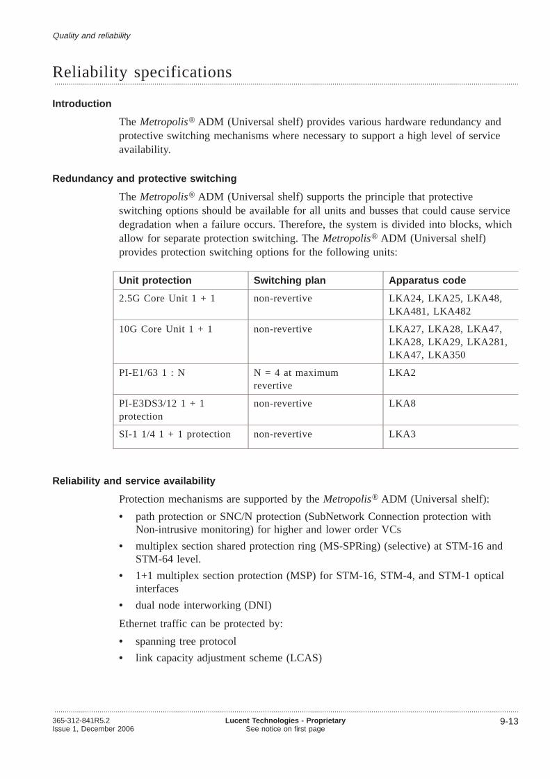
Reliability specifications...................................................................................................................................................................................................................................
Introduction
The Metropolis® ADM (Universal shelf) provides various hardware redundancy andprotective switching mechanisms where necessary to support a high level of serviceavailability.
Redundancy and protective switching
The Metropolis® ADM (Universal shelf) supports the principle that protectiveswitching options should be available for all units and busses that could cause servicedegradation when a failure occurs. Therefore, the system is divided into blocks, whichallow for separate protection switching. TheMetropolis® ADM (Universal shelf)provides protection switching options for the following units:
Unit protection Switching plan Apparatus code
2.5G Core Unit 1 + 1 non-revertive LKA24, LKA25, LKA48,LKA481, LKA482
10G Core Unit 1 + 1 non-revertive LKA27, LKA28, LKA47,LKA28, LKA29, LKA281,LKA47, LKA350
PI-E1/63 1 : N N = 4 atmaximumrevertive
LKA2
PI-E3DS3/12 1 + 1protection
non-revertive LKA8
SI-1 1/4 1 + 1 protection non-revertive LKA3
Reliability and service availability
Protection mechanisms are supported by theMetropolis® ADM (Universal shelf):
• path protection or SNC/N protection (SubNetwork Connection protection withNon-intrusive monitoring) for higher and lower order VCs
• multiplex section shared protection ring (MS-SPRing) (selective) at STM-16 andSTM-64 level.
• 1+1 multiplex section protection (MSP) for STM-16, STM-4, and STM-1 opticalinterfaces
• dual node interworking (DNI)
Ethernet traffic can be protected by:
• spanning tree protocol
• link capacity adjustment scheme (LCAS)
Quality and reliability
...................................................................................................................................................................................................................................365-312-841R5.2Issue 1, December 2006
Lucent Technologies - ProprietarySee notice on first page
9-13

Metropolis ® ADM (Universal shelf) circuit-pack fit rates
The following tables gives an overview of the circuit packs fit rates. Those FIT ratesare based on a steady state failure rate at a shelf room temperature of 25°C. The basicassumption is that the failure of any component would result in a failure of the circuitpack.
Common
Short unitname
Long description FIT rate Apparatuscode
SC1 System Controller Unit 1 5196 LKA1D
SC2 System Controller Unit 2 4814 LKA21
SC2 System Controller Unit 2 4778 LKA21B
PU Power Unit 855 PU
FAN Fan Unit 1472.3 FAN
STM-16 and STM-64 Core Units
Short unitname
Long description FIT rate Apparatuscode
SI-L16.1 C2/1 Core Unit 64/32 2.5G 7053 LKA24
SI-L16.2 C2/1 Core Unit 64/32 2.5G 7053 LKA25
SI-16 SFP C2/4 Core Unit 4 x STM-16 SFPCC-272/128 (without SFP)
7324 LKA48
SI-16 SFP C3/1 Core Unit 1 x STM-16 SFPCC-176/64 (without SFP)
6617 LKA481
SI-16 VH C3/1OBA
Core Unit 1 x STM-16 VHCC-176/64 OBA
7570 LKA482
SI-L64.2, C1/1 Core Unit 256/64 10G 13824 LKA26
SI-S64.2, C1/1 Core Unit 256/64 10G 12834 LKA27
SI-I64.1r C1 Core Unit 256/64 10G 11546 LKA47
SI-L64.2 C2/1 Core Unit 272/128 10G 11788 LKA28
SI-U64.2 C2/1 Core Unit 272/128 10G 7935 LKA281
SI-S64.2 C2/1 Core Unit 272/128 10G 11291 LKA29
SI-I64.1r C2/1 Core Unit 272/128 10G 8190 LKA49
SI-V64.2 C2/1 Core Unit 272/128 10G 12034 LKA350
Quality and reliability Reliability specifications
....................................................................................................................................................................................................................................
9-14 Lucent Technologies - ProprietarySee notice on first page
365-312-841R5.2Issue 1, December 2006
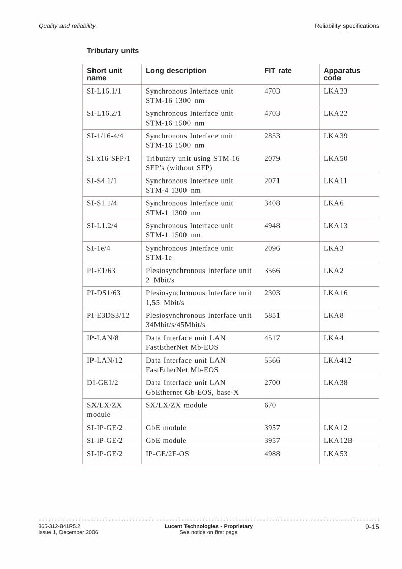
Tributary units
Short unitname
Long description FIT rate Apparatuscode
SI-L16.1/1 Synchronous Interface unitSTM-16 1300 nm
4703 LKA23
SI-L16.2/1 Synchronous Interface unitSTM-16 1500 nm
4703 LKA22
SI-1/16-4/4 Synchronous Interface unitSTM-16 1500 nm
2853 LKA39
SI-x16 SFP/1 Tributary unit using STM-16SFP’s (without SFP)
2079 LKA50
SI-S4.1/1 Synchronous Interface unitSTM-4 1300 nm
2071 LKA11
SI-S1.1/4 Synchronous Interface unitSTM-1 1300 nm
3408 LKA6
SI-L1.2/4 Synchronous Interface unitSTM-1 1500 nm
4948 LKA13
SI-1e/4 Synchronous Interface unitSTM-1e
2096 LKA3
PI-E1/63 Plesiosynchronous Interface unit2 Mbit/s
3566 LKA2
PI-DS1/63 Plesiosynchronous Interface unit1,55 Mbit/s
2303 LKA16
PI-E3DS3/12 Plesiosynchronous Interface unit34Mbit/s/45Mbit/s
5851 LKA8
IP-LAN/8 Data Interface unit LANFastEtherNet Mb-EOS
4517 LKA4
IP-LAN/12 Data Interface unit LANFastEtherNet Mb-EOS
5566 LKA412
DI-GE1/2 Data Interface unit LANGbEthernet Gb-EOS, base-X
2700 LKA38
SX/LX/ZXmodule
SX/LX/ZX module 670
SI-IP-GE/2 GbE module 3957 LKA12
SI-IP-GE/2 GbE module 3957 LKA12B
SI-IP-GE/2 IP-GE/2F-OS 4988 LKA53
Quality and reliability Reliability specifications
....................................................................................................................................................................................................................................365-312-841R5.2Issue 1, December 2006
Lucent Technologies - ProprietarySee notice on first page
9-15

Paddle boards
Short unitname
Long description FIT rate Apparatuscode
PB-1/75/P4S Paddle Board STM1e Protection 327 PBG 2
PB-E3DS3/12 Paddle Board 34/45 Mbit/s 266 PBG 4
PB-E3DS3/P75/12
Paddle Board 34/45 Mbit/sProtection
1126 PBG 1
PB-DS1/P100/63
Paddle Board 1,55 Mbit/s,100 Ω Protection
271 PBE 12
PB-E1/75/63 Paddle Board 2 Mbit/s, 75Ω 980 PBE 5
PB-E1/P120/63 Paddle Board 2 Mbit/s, 120Ω 980 PBE 6
PB-E1/P75/63 Paddle Board 2 Mbit/s, 75ΩProtection
980 PBE 3
PB-E1/P75/63 Paddle Board 2 Mbit/s, 75ΩProtection, Sub-D conn.
576 PBE3D
PB-E1/120/P63 Paddle Board 2 Mbit/s, 120Ω980Protection
584 PBE 4
PB-E1/120/P63 63 × 2 Mbit/s, 120Ω (1:Nprotected/un-protected)
584 PBE 41
PB-LAN/100/8 IO module 100BASE-T 763 PBG 1
PB OPT/12SFP
Paddle Brd. 12xLAN SFP 1106 PBO12
PB LAN100/12SFP
Paddle Brd. 12xLAN 100 Ohm 759 PBL12
PB-E3DS3/P75/12
PB 12 x E3/DS3 (Prot.1+1) 1126 PBP1
PB-1/P75/4D PB 4xSTM-1 (Prot.1+1) 604 PBP2
PB-1/75/12S PB 12xSTM-1e Un-protected 1432 PBP5
PB-1/P75/12D PB 12xSTM-1e (Prot. 1+1) 1948 PBP6
PB-STM-1o/6 PB 6xSTM-1o 478 PBP8
SFPs
SFP name FIT rates Apparatuscode
SFP I-16, 2Km 544 OM2G5-I16
SFP L-16.1, LR-1, 40km 864 OM2G5-L16.1
SFP L-16.2, LR-2, 80km 960 OM2G5-L16.2
Quality and reliability Reliability specifications
....................................................................................................................................................................................................................................
9-16 Lucent Technologies - ProprietarySee notice on first page
365-312-841R5.2Issue 1, December 2006

SFP name FIT rates Apparatuscode
SFP 2G5-S16.1, 15km 450 OM2G5-S16.1
SFP SH S-4.1, 15Km 968 OM622M-S4.1
SFP L-4.1, 40Km 556 OM622M-L4.1
SFP L-4.2, 80Km 548 OM622M-L4.2
SFP S-1.1, 15Km 544 OM155M-S1.1
SFP L-1.1, 40Km 552 OM155M-L1.1
SFP L-1.2, LH 80Km 538 OM155M-L1.2
SFP SFW-1490 BD-D 450 OM155SF1
SFP SFW-1310 BD-U 450 OM155SF2
STM-16 cWDM SFP color 13 (1510nm) 80 km 772 OM16CL51
STM-16 cWDM SFP color 14 (1530nm) 80 km 772 OM16CL53
STM-16 cWDM SFP color 15 (1550nm) 80 km 772 OM16CL55
STM-16 cWDM SFP color 16 (1570nm) 80 km 772 OM16CL57
STM-16 cWDM SFP color 13 (1510nm) 40 km 538 OM16CS51
STM-16 cWDM SFP color 14 (1530nm) 40 km 538 OM16CS53
STM-16 cWDM SFP color 15 (1550nm) 40 km 538 OM16CS55
STM-16 cWDM SFP color 16 (1570nm) 40 km 538 OM16CS57
SFP 100 BaseX Ethernet 10km 450 OM100B-LX
SFP GbE 500m 500 OMGBE-SX
SFP GbE 5km 105 OMGBE-LX
SFP GbE 70km (supplier: JDSU) 500 OMGBE-ZX
SFP GbE 70km (supplier: Excelight) 280 OMGBE-ZX
Dispersion Compensation Modules
Short name Fit rate
DCM/LC CPL DK-50 160
DCM/LC CPL DK-60 160
Miscellaneous discretes
Short name Fit rate
MIO-L 214
MIO-R 298
Quality and reliability Reliability specifications
....................................................................................................................................................................................................................................365-312-841R5.2Issue 1, December 2006
Lucent Technologies - ProprietarySee notice on first page
9-17
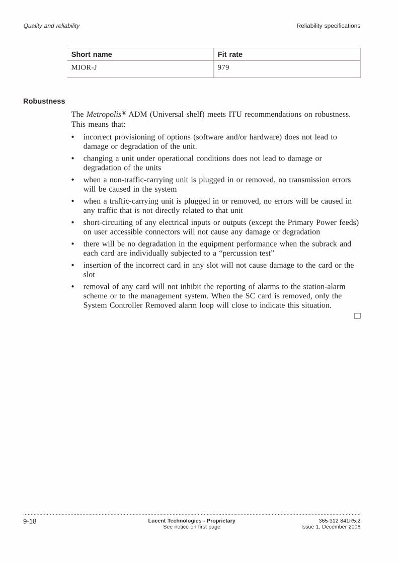
Short name Fit rate
MIOR-J 979
Robustness
The Metropolis® ADM (Universal shelf) meets ITU recommendations on robustness.This means that:
• incorrect provisioning of options (software and/or hardware) does not lead todamage or degradation of the unit.
• changing a unit under operational conditions does not lead to damage ordegradation of the units
• when a non-traffic-carrying unit is plugged in or removed, no transmission errorswill be caused in the system
• when a traffic-carrying unit is plugged in or removed, no errors will be caused inany traffic that is not directly related to that unit
• short-circuiting of any electrical inputs or outputs (except the Primary Power feeds)on user accessible connectors will not cause any damage or degradation
• there will be no degradation in the equipment performance when the subrack andeach card are individually subjected to a “percussion test”
• insertion of the incorrect card in any slot will not cause damage to the card or theslot
• removal of any card will not inhibit the reporting of alarms to the station-alarmscheme or to the management system. When the SC card is removed, only theSystem Controller Removed alarm loop will close to indicate this situation.
Quality and reliability Reliability specifications
....................................................................................................................................................................................................................................
9-18 Lucent Technologies - ProprietarySee notice on first page
365-312-841R5.2Issue 1, December 2006

10 10Technical specifications
Overview...................................................................................................................................................................................................................................
Purpose
This chapter provides the technical specifications of theMetropolis® ADM (Universalshelf):
The specifications are used to plan theMetropolis® ADM (Universal shelf) networkelement in an existing or a new network.
Contents
Optical interfaces 10-2
Electrical interfaces 10-21
Mapping structure 10-22
Transmission performance 10-23
Timing, network synchronization and timing references 10-24
Power specifications 10-26
Physical system specifications 10-31
Network management 10-33
Bandwidth management 10-34
Processing of overhead bytes 10-35
OAM&P 10-38
Performance monitoring 10-39
Supervision and alarms 10-41
Spare part information 10-43
...................................................................................................................................................................................................................................365-312-841R5.2Issue 1, December 2006
Lucent Technologies - ProprietarySee notice on first page
10-1
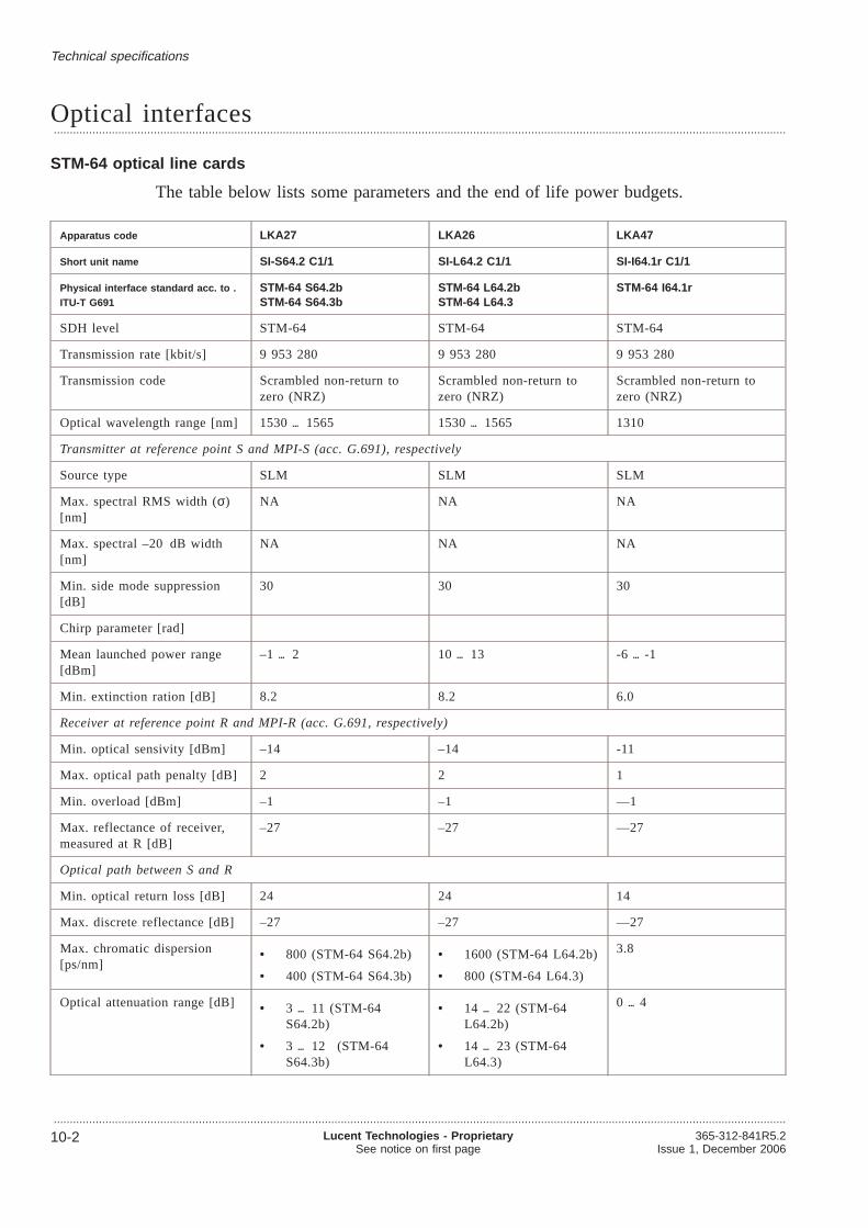
Optical interfaces...................................................................................................................................................................................................................................
STM-64 optical line cards
The table below lists some parameters and the end of life power budgets.
Apparatus code LKA27 LKA26 LKA47
Short unit name SI-S64.2 C1/1 SI-L64.2 C1/1 SI-I64.1r C1/1
Physical interface standard acc. to .ITU-T G691
STM-64 S64.2bSTM-64 S64.3b
STM-64 L64.2bSTM-64 L64.3
STM-64 I64.1r
SDH level STM-64 STM-64 STM-64
Transmission rate [kbit/s] 9 953 280 9 953 280 9 953 280
Transmission code Scrambled non-return tozero (NRZ)
Scrambled non-return tozero (NRZ)
Scrambled non-return tozero (NRZ)
Optical wavelength range [nm] 1530 1565 1530 1565 1310
Transmitter at reference point S and MPI-S (acc. G.691), respectively
Source type SLM SLM SLM
Max. spectral RMS width (σ)[nm]
NA NA NA
Max. spectral –20 dB width[nm]
NA NA NA
Min. side mode suppression[dB]
30 30 30
Chirp parameter [rad]
Mean launched power range[dBm]
–1 2 10 13 -6 -1
Min. extinction ration [dB] 8.2 8.2 6.0
Receiver at reference point R and MPI-R (acc. G.691, respectively)
Min. optical sensivity [dBm] –14 –14 -11
Max. optical path penalty [dB] 2 2 1
Min. overload [dBm] –1 –1 —1
Max. reflectance of receiver,measured at R [dB]
–27 –27 —27
Optical path between S and R
Min. optical return loss [dB] 24 24 14
Max. discrete reflectance [dB] –27 –27 —27
Max. chromatic dispersion[ps/nm]
• 800 (STM-64 S64.2b)
• 400 (STM-64 S64.3b)
• 1600 (STM-64 L64.2b)
• 800 (STM-64 L64.3)
3.8
Optical attenuation range [dB] • 3 11 (STM-64S64.2b)
• 3 12 (STM-64S64.3b)
• 14 22 (STM-64L64.2b)
• 14 23 (STM-64L64.3)
0 4
Technical specifications
...................................................................................................................................................................................................................................
10-2 Lucent Technologies - ProprietarySee notice on first page
365-312-841R5.2Issue 1, December 2006

The table below lists some parameters and the end of life power budgets of theSTM-64 optical line cards.
Apparatus code LKA29 LKA28 LKA281 LKA49 LKA350
Short unit name SI-S64.2 C2/1 SI-L64.2 C2/1 SI-U64.2 C2/1 SI-I64.1r C2/1 SI-V64.2 C2/1
Physical interfacestandard acc. to . ITU-TG691
STM-64 S64.2bSTM-64 S64.3b
STM-64 L64.2cSTM-64 L64.3
STM-64 L64.2cSTM-64 L64.3
STM-64 I64.1r not standardcompliant (closeto L64.2c)
SDH level STM-64 STM-64 STM-64 STM-64 STM-64
Transmission rate[kbit/s]
9 953 280 9 953 280 9 953 280 9 953 280 9 953 280
Transmission code Scramblednon-return tozero (NRZ)
Scramblednon-return tozero (NRZ)
Scramblednon-return tozero (NRZ)
Scramblednon-return tozero (NRZ)
Scramblednon-return tozero (NRZ)
Optical wavelengthrange [nm]
1530 1565 1530 1565 1552.52 1310 1530 1565
Transmitter at reference point S and MPI-S (acc. G.691), respectively
Source type SLM SLM EML SLM SLM
Max. spectral RMSwidth (σ) [nm]
NA NA NA NA NA
Max. spectral–20 dB width [nm]
NA NA < 1 NA NA
Min. side modesuppression [dB]
30 30 30 30 30
Chirp parameter[rad]
-0.6 -0.75
Mean launchedpower range [dBm]
–1 2 0 4 15,5 17 (T-16OBA)
12,5 14 (T-13OBA)
9,5 11 (T-10OBA)
-6 -1 11 14
Min. extinctionratio [dB]
8.29 9 9 6.0 10
Receiver at reference point R and MPI-R (acc. G.691, respectively)
Min. opticalsensivity [dBm]
–13 –24 –24 (R)
–26,5 (MPI-R)
-11 -24
Max. optical pathpenalty [dB]
2 2 (over G.652fiber) / 1 (overG.655 fiber)
2 1 2 (over G.652fiber) / 1 (overG.653 and G.655fiber)
Min. overload[dBm]
–1 –7 –7 (R)
–17 (MPI-R)
—1 -7
Max. reflectance ofreceiver, measuredat MPI-R [dB]
–27 –27 –27 —27 -27
Optical path between S and R
Technical specifications Optical interfaces
...................................................................................................................................................................................................................................365-312-841R5.2Issue 1, December 2006
Lucent Technologies - ProprietarySee notice on first page
10-3

Apparatus code LKA29 LKA28 LKA281 LKA49 LKA350
Short unit name SI-S64.2 C2/1 SI-L64.2 C2/1 SI-U64.2 C2/1 SI-I64.1r C2/1 SI-V64.2 C2/1
Physical interfacestandard acc. to . ITU-TG691
STM-64 S64.2bSTM-64 S64.3b
STM-64 L64.2cSTM-64 L64.3
STM-64 L64.2cSTM-64 L64.3
STM-64 I64.1r not standardcompliant (closeto L64.2c)
Min. optical returnloss [dB]
24 24 24 14 24
Max. discretereflectance [dB]
–27 –27 –27 –27 -27
Max. chromaticdispersion [ps/nm]
• 800(STM-64S64.2b)
• 400(STM-64S64.3b)
1600 (STM-64L64.2c)
2550 3.8 2400 (over G.652fiber)
Optical attenuationrange [dB]
• 3 11(STM-64S64.2b)
• 3 12(STM-64S64.3b)
11 22 (STM-64L64.2b)
• 34 42(with T-16booster andDCM-80)
• 31 39(with T-13booster andDCM-80)
• 38 36(with T-10booster andDCM-80)
0 4 21 33
STM-16 optical line cards
The table below lists some parameters and the end of life power budgets.
Apparatus code LKA24 LKA25 LKA22 LKA23
Short unit name SI-L16.1 C2/1 SI-L16.2 C2/1 L16.2 L16.1
Physical interface standard acc.to . ITU-T G957
STM-16 L16.1 STM-16 L16.2 STM-16 L16.2 STM-16 L16.1
SDH level STM-16 STM-16 STM-16 STM-16
Transmission rate [kbit/s] 2 488 320 2 488 32 2488320 +/- 20 ppm 2488320 +/- 20 ppm
Transmission code Scramblednon-return to zero(NRZ)
Scramblednon-return to zero(NRZ)
Scrambled non-returnto zero (NRZ)
Scramblednon-return to zero(NRZ)
Optical wavelength range[nm]
1280 1335 1535 1560 1535 - 1560 1280 1335
Transmitter at reference point S and MPI-S (acc. G.691), respectively
Source type SLM SLM DFB (uncooled) DFB (uncooled)
Max. spectral RMS width(σ) [nm]
NA NA NA NA
Technical specifications Optical interfaces
...................................................................................................................................................................................................................................
10-4 Lucent Technologies - ProprietarySee notice on first page
365-312-841R5.2Issue 1, December 2006
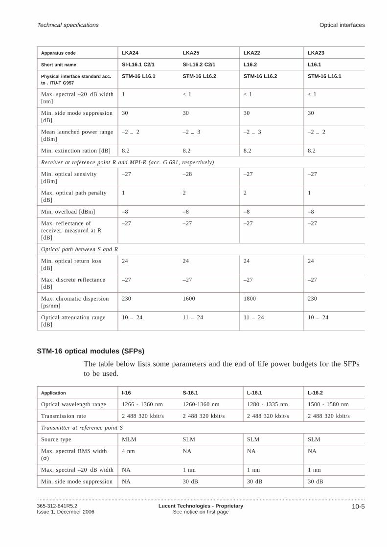
Apparatus code LKA24 LKA25 LKA22 LKA23
Short unit name SI-L16.1 C2/1 SI-L16.2 C2/1 L16.2 L16.1
Physical interface standard acc.to . ITU-T G957
STM-16 L16.1 STM-16 L16.2 STM-16 L16.2 STM-16 L16.1
Max. spectral –20 dB width[nm]
1 < 1 < 1 < 1
Min. side mode suppression[dB]
30 30 30 30
Mean launched power range[dBm]
–2 2 –2 3 –2 3 –2 2
Min. extinction ration [dB] 8.2 8.2 8.2 8.2
Receiver at reference point R and MPI-R (acc. G.691, respectively)
Min. optical sensivity[dBm]
–27 –28 –27 –27
Max. optical path penalty[dB]
1 2 2 1
Min. overload [dBm] –8 –8 –8 –8
Max. reflectance ofreceiver, measured at R[dB]
–27 –27 –27 –27
Optical path between S and R
Min. optical return loss[dB]
24 24 24 24
Max. discrete reflectance[dB]
–27 –27 –27 –27
Max. chromatic dispersion[ps/nm]
230 1600 1800 230
Optical attenuation range[dB]
10 24 11 24 11 24 10 24
STM-16 optical modules (SFPs)
The table below lists some parameters and the end of life power budgets for the SFPsto be used.
Application I-16 S-16.1 L-16.1 L-16.2
Optical wavelength range 1266 - 1360 nm 1260-1360 nm 1280 - 1335 nm 1500 - 1580 nm
Transmission rate 2 488 320 kbit/s 2 488 320 kbit/s 2 488 320 kbit/s 2 488 320 kbit/s
Transmitter at reference point S
Source type MLM SLM SLM SLM
Max. spectral RMS width(σ)
4 nm NA NA NA
Max. spectral –20 dB width NA 1 nm 1 nm 1 nm
Min. side mode suppression NA 30 dB 30 dB 30 dB
Technical specifications Optical interfaces
...................................................................................................................................................................................................................................365-312-841R5.2Issue 1, December 2006
Lucent Technologies - ProprietarySee notice on first page
10-5

Application I-16 S-16.1 L-16.1 L-16.2
Mean launched power (max) -3 dBm 0 dBm 3 dBm 3 dBm
Mean launched power (min) –10 dBm –5 dBm –2 dBm –2 dBm
Extinction ratio (min) 8.2 dB 8.2 dB 8.2 dB 8.2dB
Optical path between S and R
Optical return loss of thecable plant at point Sincluding the opticalconnector
14 dB 24 dB 24 dB 24 dB
Max. chromatic dispersion 12 ps/nm NA 230 ps/nm 1600 ps/nm
Optical attenuation range 0 7 dB 0 12 dB 10 24 dB 10 24 dB
Max. discrete reflectance –27 dB -27 dB –27 dB –27 dB
Optical return loss of thecable plant at point Sincluding the opticalconnector
14 dB 24 dB 24 dB 24 dB
Receiver at reference point R
Min. optical sensivity (BER= 1 × 10 -10)
–18 dBm –18 dBm –27 dBm –28 dBm
Min. optical sensivity (BER= 1 × 10 -12)
–17 dBm –17 dBm –26 dBm –27 dBm
Max. optical path penalty 1 dB 1 dB 1 dB 2 dB
Min. overload –3 dBm 0 dBm –9 dBm –9 dBm
Min. return loss at receiver,measured at R
27 dB 27 dB 27 dB 27 dB
The table below lists some parameters and the end of life power budgets for theCWDM SFPs to be used in the 4 x STM-16 SFP CC-272/128 core unit, the 2.5G CoreUnit 176/64 (LKA481), the 2.5G Core Unit 176/64 (LKA482) and the STM-x16 SFP/1(LKA50). Deviating values recommended by G.695 are in brackets.
Apparatus code OM16CS47OM16CS49OM16CS51OM16CS53OM16CS55OM16CS57OM16CS59OM16CS61
OM16CL47OM16CL49OM16CL51OM16CL53OM16CL55OM16CL57OM16CL59OM16CL61
Physical interface standard acc. to . ITU-T S-C8S1-1D2 S-C8L1-1D2
Parameter Units
Maximum number of channels 8 8
Bit rate / line coding of optical tributarysignals
kbit/s NRZ / 2488320 NRZ / 2488320
Maximum bit error ratio - 10-12 12-Oct
Fibre type G.652, G.653, G.655 G.652, G.653, G.655
Technical specifications Optical interfaces
...................................................................................................................................................................................................................................
10-6 Lucent Technologies - ProprietarySee notice on first page
365-312-841R5.2Issue 1, December 2006

Apparatus code OM16CS47OM16CS49OM16CS51OM16CS53OM16CS55OM16CS57OM16CS59OM16CS61
OM16CL47OM16CL49OM16CL51OM16CL53OM16CL55OM16CL57OM16CL59OM16CL61
Physical interface standard acc. to . ITU-T S-C8S1-1D2 S-C8L1-1D2
Parameter Units
Interface at point SS
Maximum mean channel output power dBm 5 5
Minimum mean channel output power dBm 0 0
Central wavelength nm 1511 + 20m
(m = 0 to 3)
1511 + 20m
(m = 0 to 3)
Maximum central wavelength deviation nm +/- 6.5 +/- 6.5
Minimum extinction ratio dB 8.2 8.2
Eye mask - STM-16 per G.957 STM-16 per G.957
Optical path from point SS and RS
Maximum channel insertion loss dB 17.3 (16.5) 25.5
Minimum channel insertion loss dB 5 13 (14)
Maximum dispersion ps / nm refer to“Wavelengthspecific maximumcumulativedispersion” (p. 10-7)
refer to “Wavelengthspecific maximumcumulative dispersion”(p. 10-7)
Minimum optical return loss at SS dB 24 24
Maximum discrete reflectance between SS andRS
dB -27 -27
Maximum differential group delay ps 120 120
Maximum optical cross talk dB 20 20
Interface at point RS
Maximum mean channel input power dBm 0 -8 (-9)
Minimum sensitivity dBm -18.5 (-18) 28
Maximum optical path penalty dB 1.2 (1,5) 2.5
Maximum reflectance of receiver dB -27 -27
Wavelength specific maximum cumulative dispersion
wavelength in vacuum frequency Maximum cumulative dispersion [ps/nm]
[nm] [THz] S-C8S1-1D2 S-C8L1-1D2
1471 203.802 626 1044
1491 201.068 688 1147
1511 198.407 749 1248
Technical specifications Optical interfaces
...................................................................................................................................................................................................................................365-312-841R5.2Issue 1, December 2006
Lucent Technologies - ProprietarySee notice on first page
10-7

wavelength in vacuum frequency Maximum cumulative dispersion [ps/nm]
1531 195.815 807 1345
1551 193.29 863 1438
1571 190.829 918 1530
1591 188.43 960 1600
1611 186.091 960 1600
STM-4 optical tributary cards
The table below lists some parameters and the end of life power budgets.
Apparatus code LKA11 LKA14
Short unit name SI-S4.1/1 SI-L4.2/1
Physical interface standard acc. to . ITU-T G957 STM-4 S4.1 STM-4 L4.2
SDH level STM-4 STM-4
Transmission rate [kbit/s] 622 080 622 080
Transmission code Scrambled non-return to zero(NRZ)
Scrambled non-return to zero(NRZ)
Optical wavelength range [nm] 1274 1356 1530 1565
Transmitter at reference point S and MPI-S (acc. G.691), respectively
Source type MLM SLM
Max. spectral RMS width (σ) [nm] 2.5 NA
Max. spectral –20 dB width [nm] NA < 1
Min. side mode suppression [dB] NA 30
Mean launched power range [dBm] –15 –8 –3 2
Min. extinction ration [dB] 8.2 10
Receiver at reference point R and MPI-R (acc. G.691, respectively)
Min. optical sensivity [dBm] –28 –28
Max. optical path penalty [dB] 1 1
Min. overload [dBm] –8 –8
Max. reflectance of receiver, measuredat R [dB]
NA –27
Optical path between S and R
Min. optical return loss [dB] NA 24
Max. discrete reflectance [dB] NA –27
Max. chromatic dispersion [ps/nm] 74 2000
Optical attenuation range [dB] 0 12 10 24
Technical specifications Optical interfaces
...................................................................................................................................................................................................................................
10-8 Lucent Technologies - ProprietarySee notice on first page
365-312-841R5.2Issue 1, December 2006

STM-4 optical modules (SFPs)
The table below lists some parameters and the end of life power budgets for theSTM-4 optical modules SFPs to be used together with the Multi-STM Main Board(12*STM-1e, 16*STM-1o, 4*STM-4) (LKA39) .
Application STM-4 Short HaulS-4.1
STM-4 Long Haul L-4.1 STM-4 Long Haul L-4.2
Operating wavelength range 1274-1356 nm 1280-1335 nm 1480-1580 nm
Source type MLM SLM SLM
Spectral width at -20 dB (max) NA 1 nm 1 nm
RMS spectral width (max) 2.5 nm NA NA
Mean launched power (max) -8 dBm +2 dBm +2 dBm
Mean launched power (min) -15 dBm -3 dBm -3 dBm
Side mode suppression ratio (min) NA 30 dB 30 dB
Extinction ratio (min) 8.2 dB 10 dB 10 dB
Mask of the eye diagram of the optical transmitsignal
see G.957 see G.957 see G.957
Optical path between points S and R
Maximum dispersion 74 ps/nm NA NA
Optical attenuation range 0 - 12 dB 10 - 24 dB 10 - 24 dB
Optical return loss of the cable plant at point Sincluding the optical connector
NA 25 dB 24 dB
Receiver at reference point R
Sensitivity (min) at BER = 1 × 10 -10 -28 dBm -28 dBm -28 dBm
Overload (min) -8 dBm -8 dBm -8 dBm
Optical path penalty < 1 dB < 1 dB < 1 dB
Optical return loss of the receiver (min) NA 14 dB 27 dB
STM-1 optical tributary cards
The table below lists some parameters and the end of life power budgets.
Apparatus code LKA6 LKA13
Short unit name SI-S1.1/4 SI-L1.2/4
Physical interface standard acc. to . ITU-T G957 STM-1 S1.1 STM-1 L1.2
SDH level STM-1 STM-1
Transmission rate [kbit/s] 155 520 155 520
Transmission code Scrambled non-return to zero(NRZ)
Scrambled non-return to zero(NRZ)
Optical wavelength range [nm] 1274 1356 1480 1580
Transmitter at reference point S and MPI-S (acc. G.691), respectively
Technical specifications Optical interfaces
...................................................................................................................................................................................................................................365-312-841R5.2Issue 1, December 2006
Lucent Technologies - ProprietarySee notice on first page
10-9

Apparatus code LKA6 LKA13
Short unit name SI-S1.1/4 SI-L1.2/4
Physical interface standard acc. to . ITU-T G957 STM-1 S1.1 STM-1 L1.2
Source type MLM SLM
Max. spectral RMS width (σ) [nm] 4 NA
Max. spectral –20 dB width [nm] NA < 1
Min. side mode suppression [dB] NA 30
Mean launched power range [dBm] –15 –8 –5 –0
Min. extinction ration [dB] 8.2 10
Receiver at reference point R and MPI-R (acc. G.691, respectively)
Min. optical sensivity [dBm] –28 –34
Max. optical path penalty [dB] 1 1
Min. overload [dBm] –8 –10
Max. reflectance of receiver, measuredat R [dB]
NA 25
Optical path between S and R
Min. optical return loss [dB] NA 20
Max. discrete reflectance [dB] NA –25
Max. chromatic dispersion [ps/nm] 185 NA
Optical attenuation range [dB] 10 28
STM-1 optical modules (SFPs)
The table below lists some parameters and the end of life power budgets for theSTM-1 optical modules SFPs to be used together with the Multi-STM Main Board(12*STM-1e, 16*STM-1o, 4*STM-4) (LKA39) .
Application STM-1 Short Haul S-1.1(I-1)
STM-1 Long Haul L-1.1 STM-1 Long Haul L-1.2
Operating wavelength range 1260-1360 nm 1270-1360 nm 1480-1580 nm
Transmitter at reference point S
Source type MLM SLM / MLM SLM
Spectral width at -20 dB (max) NA 1 nm (SLM) 1 nm
RMS spectral width (max) 7.7 nm 3 nm (MLM) NA
Mean launched power (max) -8 dB 0 dB 0 dB
Mean launched power (min) -15 dB -5 dB -5 dB
Side mode suppression ratio (min) NA 30 dB / NA 30 dB
Extinction ratio (min) 8.2 dB 10 dB 10 dB
Technical specifications Optical interfaces
...................................................................................................................................................................................................................................
10-10 Lucent Technologies - ProprietarySee notice on first page
365-312-841R5.2Issue 1, December 2006

Application STM-1 Short Haul S-1.1(I-1)
STM-1 Long Haul L-1.1 STM-1 Long Haul L-1.2
Mask of the eye diagram of theoptical transmit signal
see G.957 see G.957 see G.957
Optical path between points S and R
Maximum dispersion 96 ps/nm NA / 246 ps/nm NA
Attenuation range 0 - 12 dB 10 - 28 dB 10 - 28 dB
Optical return loss of the cableplant at point S including theoptical connector
NA NA 20 dB
Receiver at reference point R
Sensitivity (min) at BER = 1 × 10⁻¹⁰
-28 dBm -34 dBm -34 dBm
Overload (min) -8 dBm -10 dBm -10 dBm
Optical path penalty < 1 dB < 1 dB < 1 dB
Optical return loss of the receiver(min)
NA NA > 25 dB
Multi rate Single Fiber optical modules (SFPs)
The table below lists some parameters and the end of life power budgets for theSTM-1, STM-4, 1 GbE Single-Fiber (Bidirectional) Short Haul optical modules (SFPs).
Unit Value
Application S-1.2/S-4.2 Downstream1000BASE-BX10-D
S-1.1/S-4.1 Upstream1000BASE-BX10-U
Data rate Mbit/s 155/622 1250 155/622 1250
Target distance km 15 20 15 20
Transmitter at reference point S / TP2
Source type SLM SLM
Wavelength nm 1480 - 1500 1260 - 1360
Max. Spectral width at-20 dB
nm 1 1
Mean launched power(max)
0 0
Mean launched power(min)
dBm -6 -6
Maximum meanlaunched power in caseTx_Disable = high
dBm -45 -45
Minimum extinctionratio
dB 6 6
Transmitter eye maskdefinition
see G.957 see Table 59-6,IEEE802.3ah
see G.957 see Table 59-6,IEEE802.3ah
Technical specifications Optical interfaces
...................................................................................................................................................................................................................................365-312-841R5.2Issue 1, December 2006
Lucent Technologies - ProprietarySee notice on first page
10-11

Unit Value
Application S-1.2/S-4.2 Downstream1000BASE-BX10-D
S-1.1/S-4.1 Upstream1000BASE-BX10-U
Data rate Mbit/s 155/622 1250 155/622 1250
Target distance km 15 20 15 20
Maximum reflectance oftransmitter, measured atS / TP2
dB NA -12 NA -12
Maximum optical pathpenalty / Maximumtransmitter anddispersion penalty
dB 1 3.3 1 3.3
Optical path between S / TP2 and R / TP3
Available power budget(BER = 1 × 10⁻¹⁰)
dB 13.5 - 13.5 -
Available power budget(BER = 1 × 10-12)
dB 12.5 12.5 12.5 12.5
Minimum attenuation dB 0 0 0 0
Maximum dispersion ps/nm 275 275 132 132
Receiver at reference point R / TP3
Operating wavelengthrange
nm 1260 - 1360 1480 - 1500
Minimum sensitivity (@BER = 1*10-10)
dBm -19,5 - -19,5 -
Minimum sensitivity (@BER = 1*10-12)
dBm -18,5 -18,5 -18,5 -18,5
Minimum overload dBm 0 0 0 0
Maximum reflectance ofreceiver, measured at R/ TP3
dB -12 -12
Specification 100BASE-LX10 pluggable optic
The 100BASE-LX pluggable optic are insert into a paddle board PBO12 (up to 12100BASE-LX10 SFP transceivers), which is connected to a LKA412.
Unit Value
Application code(IEEE802.3ah)
100BASE-LX10 single-mode
Data rate MBd 125 +/- 50 ppm
Target distance km 10
Transmitter at reference point TP2
Source type MLM
Technical specifications Optical interfaces
...................................................................................................................................................................................................................................
10-12 Lucent Technologies - ProprietarySee notice on first page
365-312-841R5.2Issue 1, December 2006

Unit Value
Application code(IEEE802.3ah)
100BASE-LX10 single-mode
Nominal center wavelength nm 1260 - 1360
Spectral characteristics
spectral width RMS (s) nm 7.7
Mean launched power
maximum dBm -8
minimum dBm -15
Maximum mean launched powerfor Tx disabled
dBm -45
Minimum extinction ratio dB 5
Transmitter eye mask definition(X1, X2, X3, Y1, Y2, Y3, Y4)
UI see Table 58-3, IEEE802.3ah
Rise and fall time (10%/90%,unfiltered)
ns tbd
Maximum transmitter total jitter(peak to peak)
ns 3.2
Maximum optical return losstolerance
dB 12
Optical path between TP2 and TP3
Maximum channel insertion loss dB 6
Minimum channel insertion lossb dB 0
Minimum and maximumdispersion
ps/nm see Table 58-12, IEEE802.3ah
Maximum transmitter anddispersion penalty
dB 4.5
Receiver at reference point TP3
Operating wavelength range nm 1260 - 1360
Minimum sensitivity (@ BER =1.0 *10-10)
dBm -26
Minimum sensitivity (@ BER =1.0*10-12)
dBm -25
Stressed receiver sensitivity dBm -20.1
Minimum overload dBm -8
Total jitter (peak to peak) at TP3 ns 3.54
Minimum LOS assert level dBm -45
Maximum LOS de-assert level dBm 25
Technical specifications Optical interfaces
...................................................................................................................................................................................................................................365-312-841R5.2Issue 1, December 2006
Lucent Technologies - ProprietarySee notice on first page
10-13

Unit Value
Application code(IEEE802.3ah)
100BASE-LX10 single-mode
LOS hysteresis
maximum dB 6
minimum dB 0.5
Maximum reflectance ofreceiver, measured at TP3
dB -12
Specification 1000BASE-SX pluggable optic
The 1000BASE-SX pluggable optic (850 nm short haul, multi-mode) according toFDA/CDRH - 21 CFR 1010 & 1040 / IEC 60825).
The 1000BASE-SX pluggable optic complies with IEEE 802.3-2000 Clause 38.
The table below describes the various operating ranges for the 1000BASE-SXpluggable optic over each optical fiber type.
Fiber Type Modal Bandwidth @850 nm(min. overfilled launch)(MHz × km)
Minimum range(m)
62.5 µm MMF 160 2 220
62.5 µm MMF 200 2 275
50 µm MMF 400 2 500
50 µm MMF 500 2 550
10 µm MMF N/A Not supported
The following table lists the specific optical characteristics for a 1000BASE-SXpluggable optic.
Application 1000BASE-SX
Bit rate 1.25Gb/s +/-100ppm
Operating wavelength range 760 - 860 nm
Transmitter characteristics
Transmitter type Shortwave Laser
Trise/Tfall (max, 20–80%,λ > 830 nm) 0.26 ns
Trise/Tfall (max, 20–80%,λ ≤ 830 nm) 0.21 ns
RMS spectral width (max) 0.85 nm
Technical specifications Optical interfaces
...................................................................................................................................................................................................................................
10-14 Lucent Technologies - ProprietarySee notice on first page
365-312-841R5.2Issue 1, December 2006

Application 1000BASE-SX
Average launch power (max) Is the class 1 safety limit as definedby IEEE 802.3–2000 Clause 38.7.2.
Average launch power (min) –9.5 dBm
Average launch power of OFF transmitter (max) –30 dBm
Extinction ratio (min) 9 dB
RIN (max) –117 dB/Hz
Mask of the eye diagram of the optical transmitsignal
see IEEE802.3
Receive Characteristics
Average receive power (max) 0 dBm
Receive sensitivity –17 dBm
Return loss (min) 12 dB
Stressed receive sensitivity
(measured with conformance test signal at TP3for BER = 10–12 at the eye center)
–12.5 dBm (62.5 µm MMF)
–13.5 dBm (50 µm MMF)
The following table lists the worst-case power budget and link penalties for a1000BASE-SX pluggable optic. Link penalties are used for link budget calculations.
Description Unit 62.5 µm MMF 50 µm MMF
Modal bandwidth asmeasured at850 nm (minimum,overfilled launch)
MHz× km
160 200 400 500
Link power budget dB 7.5 7.5 7.5 7.5
Operating distance m 220 275 500 550
Channel insertionloss (a wavelengthof 830 nm is usedto calculate thevalues)
dB 2.38 2.60 3.37 3.56
Link powerpenalties (awavelength of830 nm is used tocalculate thevalues)
dB 4.27 4.29 4.07 3.57
Unallocated marginin link powerbudget (awavelength of830 nm is used tocalculate thevalues)
dB 0.84 0.60 0.05 0.37
Technical specifications Optical interfaces
...................................................................................................................................................................................................................................365-312-841R5.2Issue 1, December 2006
Lucent Technologies - ProprietarySee notice on first page
10-15

Specification 1000BASE-LX pluggable optic
The 1000BASE-LX pluggable optic uses a Low Power Laser (laser class 1/1 accordingto FDA/CDRH - 21 CFR 1010 & 1040 / IEC 60825).
The 1000BASE-LX pluggable optic complies with IEEE 802.3-2000 Clause 38.
The table below describes the various operating ranges for the 1000BASE-LXpluggable optic over each optical fiber type.
Fiber Type Modal Bandwidth @ 1300 nm(min. overfilled launch)(MHz × km)
Minimum range(meters)
62.5 µm MMF 500 2 to 550
50 µm MMF 400 2 to 550
50 µm MMF 500 2 to 550
10 µm SSMF N/A 2 to 5000
The following table lists the specific optical characteristics for a 1000BASE-LXpluggable optic.
Application 1000BASE-LX pluggableoptic
Bit rate 1.25Gb/s +/-100ppm
Operating wavelength range 1270 to- 1335 nm
Transmitter Characteristics
Transmitter type Shortwave Laser
Trise/Tfall (max, 20–80%) 0.26 ns
RMS spectral width (max) 4 nm
Average launch power (max) -3 dBm
Average launch power (min) -11.5 dBm (62.5 µm and 50µm MMF) / -11 dBm (10 µmSMF)
Average launch power of OFF transmitter (max) -30 dBm
Extinction ratio (min) 9 dB
Mask of the eye diagram of the optical transmitsignal
see IEEE802.3
RIN (max) -117 dB/Hz
Receive Characteristics
Average receive power (max) -3 dBm
Receive sensitivity -19 dBm
Technical specifications Optical interfaces
...................................................................................................................................................................................................................................
10-16 Lucent Technologies - ProprietarySee notice on first page
365-312-841R5.2Issue 1, December 2006

Application 1000BASE-LX pluggableoptic
Return loss (min) 12 dB
Stressed receive sensitivity
(measured with conformance test signal at TP3 forBER = 10–12 at the eye center)
-14.4 dBm
The following table lists the worst-case power budget and link penalties for a1000BASE-LX pluggable optic. Link penalties are used for link budget calculations.
Description Unit 10 µmSMF
Modal bandwidth as measured at 1300 nm (minimum,overfilled launch)
MHz× km
N/A
Link power budget dB 8
Operating distance m 5000
Channel insertion loss (a wavelength of 1270 nm is used tocalculate the values)
dB 4.57
Link power penalties (a wavelength of 1270 nm is used tocalculate the values)
dB 3.27
Unallocated margin in link power budget (a wavelength of1270 nm is used to calculate the values)
dB 0.16
Specification 1000BASE-ZX pluggable optic
The 1000BASE-ZX pluggable optic uses a Low Power Laser (laser class 1/1 accordingto FDA/CDRH - 21 CFR 1010 & 1040 / IEC 60825).
The 1000BASE-ZX pluggable optic complies with IEEE 802.3-2002 Clause 38.
The following table lists the specific optical characteristics for a 1000BASE-ZXpluggable optic.
Application 1000BASE-ZX pluggable optic
Bit rate 1.25Gb/s +/-100ppm
Operating wavelength range 1500-1580 nm
Transmitter at reference point TP2
Source type SLM
Spectral width at 20dB 1.0 nm
Side mode suppression ratio (min) 30dB
Mean launched power (max) +5 dBm
Technical specifications Optical interfaces
...................................................................................................................................................................................................................................365-312-841R5.2Issue 1, December 2006
Lucent Technologies - ProprietarySee notice on first page
10-17

Application 1000BASE-ZX pluggable optic
Mean launched power (min) 0 dBm
Extinction ratio (min) 9.0 dB
Mask of the eye diagram of the opticaltransmit signal
see IEEE802.3
Optical path between points TP2 and TP3
Optical return loss of the cable plant atpoint TP2 including the optical connector
20 dB
Maximum dispersion 1600 ps/nm
Attenuation range 5 - 21 dB
Optical path penalty (max) 1.5 dB
Receiver at reference point TP3
Minimum sensitivity -22.5 dBm
Overload (min) 0 dBm
Optical return loss of the receiver (min) 12 dB
Optical connector interfaces
The following table specifies the optical connector interfaces
Optical units Optical connectors
Tributaries: LKA6 (SI-S1.1/4), LKA11(SI-S4.1/1), LKA13 (SI-L1.2/4), LKA14(SI-L4.2/1)
SC
Ethernet: LKA12 / LKA12 B (IP-GE/2) Small Form factor Pluggable (SFP)device, normally equipped with an LCconnector.
Ethernet: LKA53 (IP-GE/2) Small Form factor Pluggable (SFP)device, normally equipped with an LCconnector.
Core Units: LKA24 (SI-L16.1 C2/1),LKA25 (SI-L16.2 C2/1), LKA26(SI-L64.2), LKA27 (SI-S64.2), LKA47(SI-I64.1r), LKA8 (SI-16SFP C2/4)
Universal build out, which allows SC, FCand ST types of connectors; default is SC.
Tributary high-density: LKA50, LKA 39 LC
Technical specifications Optical interfaces
...................................................................................................................................................................................................................................
10-18 Lucent Technologies - ProprietarySee notice on first page
365-312-841R5.2Issue 1, December 2006

Optical source and detector
The optical sources and detectors of theMetropolis® ADM (Universal shelf) have thefollowing technical specifications.
Optical circuit pack Laser type Optical detector Hazard level(IEC-60825-2)
LKA6 (SI-S1.1/4 G.9571310 nm)
FP (MLM) PIN 1
LKA11 (SI-S4.1/1) FP (MLM) PIN 1
LKA12 /LAK12B(SI-IP-GE/2)
LC 1
LKA12B (SI-IP-GE/2) LC 1
LKA13 (SI-L1.2/4G.957 1550 nm)
DFB (SLM) PIN 1
LKA14 (SI-L4.2/1) DFB (SLM) PIN 1
LKA24 (SI-L16.1 C2/1) DFB (SLM) APD 1
LKA25 (SI-L16.2 C2/1) DFB (SLM) APD 1
LKA26 (SI-L64.2b/3) DFB + OA PIN 1M
LKA27 (SI-S64.2b/3b) DFB (SLM) PIN 1
LKA53 (SI-IP-GE/2) LC 1
LKA47 (SI-I64.1r) DFB PIN 1
LKA28 (SI-L64.2 C2/1) DFB APD 1
LKA281 (SI-U64.2C2/1)
DFB+OA APD 1
LKA29 (SI-S64.2 C2/1) DFB PIN 1
LKA49 (SI-I64.1r C2/1) DFB PIN 1
LKA350 (SI-V64.2C2/1)
DFB+OA APD 1M (OA with +11 .. +14dBm)
The abbreviations used:
• APD: avalanche photo diode
• DFB: distributed feedback laser (= SLM)
• FP: fabry-perot (= MLM)
• LC: used for LC connector or LC interface
• MLM: multi longitudinal mode
• OA: optical amplifier output power 10...13 dBm at 1550 nm.
• PIN: Positive Intrinsic Negative (PIN) receiver.
• SLM: single longitudinal mode
Technical specifications Optical interfaces
...................................................................................................................................................................................................................................365-312-841R5.2Issue 1, December 2006
Lucent Technologies - ProprietarySee notice on first page
10-19

Optical safety
The system is classified and labelled as specified in IEC 60825-1 and IEC 60825-2“Radiation safety of laser products equipment, classification, requirements and usersguide”. All parts of the equipment are designed for operation and maintenance withoutany hazards to personnel from optical radiation.
Technical specifications Optical interfaces
...................................................................................................................................................................................................................................
10-20 Lucent Technologies - ProprietarySee notice on first page
365-312-841R5.2Issue 1, December 2006

Electrical interfaces...................................................................................................................................................................................................................................
Electrical interfaces
The electrical interfaces of theMetropolis® ADM (Universal shelf) have the followingtechnical specifications.
1.5 Mbit/s 2 Mbit/s 34 Mbit/s 45 Mbit/s STM-1 10/100 Mbit/sBase-T
Nominalbitrate
1544 kBit/s 2048 kBit/s 34.368 Mbit/s 44.736 Mbit/s 155.520 Mbit/s 10/100 Mbit/s
Line code AMI(AlternateMarkInversion) orB8ZS (Bipolarwith 8-ZeroSubstitution).
HDB3 (G.703) HDB3 (G.703) B3ZS (ANSIT1.102–1987)
CMI (G.703) IEEE802.3-2000
Insertion loss acc. to G.703 acc. to G.703 acc. to G.703 acc. to G.703 acc. to G.703 acc. to IEEE802.3-2000
Return loss acc. to G.703 acc. to G.703 acc. to G.703 acc. to G.703 acc. to G.703 acc. to IEEE802.3-2000
Amplitude of the DS3 output signal
The amplitude/shape of the DS3 output signal can be provisioned to match the cablebetween theMetropolis® ADM (Universal shelf) and the DDF, in such a way that thepulse shape at the DDF, which can be up to 450 feet away, meets the specification.Two signal levels can be provisioned in the transmitter, covering cable lengths between0 120 and 120 450 feet. The receiver has an automatic line build-out capability tohandle cable lengths between 0 450 feet.
Technical specifications
...................................................................................................................................................................................................................................365-312-841R5.2Issue 1, December 2006
Lucent Technologies - ProprietarySee notice on first page
10-21

Mapping structure...................................................................................................................................................................................................................................
Mapping structure
The following mapping structures are supported:
Between cross-connect and line/tributary interface, SDH mapping:
• C-4-16c↔ VC-4-16c↔ AU-4-16c ↔ AUG16 ↔ AUG64 ↔ STM-64
• C-4-16c↔ VC-4-16c↔ AU-4-16c ↔ AUG16 ↔ STM-16 (in STM-64applications)
• AU-4 ↔ AUG1 ↔ AUG4 ↔ AUG16 ↔ AUG64 ↔ STM-64
• AU-4-4c ↔ AUG4 ↔ AUG16 ↔ STM-16
• AU-4 ↔ AUG1 ↔ AUG4 ↔ AUG16 ↔ STM-16
• AU-4 ↔ AUG1 ↔ AUG4 ↔ STM-4
• AU-4 ↔ AUG1 ↔ STM-1
• AU-4 ↔ VC-4 ↔ TUG-3 ↔ TU-3 ↔ VC-3 ↔ E3/DS3
• AU-4 ↔ VC-4 ↔ TUG-3 ↔ TUG-2 ↔ TU-12 ↔ VC-12 ↔ E1
Between cross-connect and tributary interface, with conversion from TU-3 to AU-3:
• AU-4 ↔ VC-4 ↔ TUG-3 ↔ TU-3 ↔ VC-3 ↔ AU-3 ↔ AUG1 ↔ STM-1(OC-3)
• AU-4 ↔ VC-4 ↔ TUG-3 ↔ TU-3 ↔ VC-3 ↔ AU-3 AUG1 ↔ AUG4↔ STM-4 (OC-12)
Between cross-connect and tributary interface, Ethernet mapping:
• AU-4 ↔ VC-4 ↔ VC-4-Xv ↔ GFP↔ Ethernet
• AU-4 ↔ VC-4 ↔ VC-3-Xv ↔ GFP or EoS↔ Ethernet
• AU-4 ↔ VC-4 ↔ TUG-3 ↔ VC-12-Xv ↔ GFP or EoS↔ Ethernet
• STM-4 ↔ AU4 ↔ TU12 ↔ VC12-Xv ↔ GFP/LAPS/PPP↔ E/FE/GbE(LKA412)
• STM-4 ↔ AU4 ↔ TU3 ↔ VC3-Xv ↔ GFP/LAPS/PPP↔ E/FE/GbE (LKA412)
• STM-4 ↔ AU4 ↔ VC4-Xv ↔ GFP/LAPS/PPP↔ E/FE/GbE (LKA412)
Technical specifications
...................................................................................................................................................................................................................................
10-22 Lucent Technologies - ProprietarySee notice on first page
365-312-841R5.2Issue 1, December 2006

Transmission performance...................................................................................................................................................................................................................................
Specifications
The following specifications apply to theMetropolis® ADM (Universal shelf) withregard to performance:
Jitter on STM-N interfaces G.813, G.825
Jitter on PDH interfaces G.823, G.783
Error Performance G.826
Performance monitoring G.784, G.826
Technical specifications
...................................................................................................................................................................................................................................365-312-841R5.2Issue 1, December 2006
Lucent Technologies - ProprietarySee notice on first page
10-23

Timing, network synchronization and timing references...................................................................................................................................................................................................................................
The following specifications apply to theMetropolis® ADM (Universal shelf) withregard to timing and synchronization.
References
Timing and synchronization is described at
• “Timing architecture” (p. 4-46)
• “External timing reference inputs” (p. 4-46)
• “External timing reference outputs” (p. 4-48)
External timing reference signals
The table below shows the specifications for external timing reference signals.
2048 kHz, according to G.703-10
2048 kbit/s, according to G.703-6 framed according to G.704
2048 kbit/s, according to G.703-6 unframed (AIS format)
6312 kHz for NE output (required for the Japanese market )
The so-called MIOR-J unit converts two independent 2048 kHz signals coming frombackplane to two independent 6312 kHz signals towards outside. The 2048 kHz signalsare system station clock outputs.
The table below shows the specifications for timing input impedance.
Input impedance 75Ω coax
Input impedance 120Ω symmetrical
Oscillator
The internal oscillator has the following specifications:
Oscillator Specification
Built-in oscillator Stratum-3 Accuracy 4.6 ppm acc. to G.813 option 1;stability 0.37 ppm/ first 24 hours
Technical specifications
...................................................................................................................................................................................................................................
10-24 Lucent Technologies - ProprietarySee notice on first page
365-312-841R5.2Issue 1, December 2006

Timing modes
The timing modes are specified as follows:
Timing mode Specification
Free running mode Accuracy 4.6 ppm over 15 years
Hold-over mode Accuracy 4.6 ppm of the frequency of the lastsource in two weeks
Locked mode with reference to one of the
• external sync. inputs
• 2 Mbit/s tributary inputs
• STM-N inputs
Automatic ref. signal switching compliant with ETSI ETS 300 417–6
Support of Sync. Status Marker(SSM)
STM-1, STM-4, STM-16, and STM-64 interfaces2 Mbit/s framed station clock
Technical specifications Timing, network synchronization and timing references
...................................................................................................................................................................................................................................365-312-841R5.2Issue 1, December 2006
Lucent Technologies - ProprietarySee notice on first page
10-25

Power specifications...................................................................................................................................................................................................................................
Power supply voltage
Voltage range, all components –48 to –60 V battery voltages, CEPTT/TR02-02 (–40.5 V minimum, –72 Vmaximum)
Power feeders Two power feeders
Worst case system power dissipation
Configuration Power dissipation
Metropolis® ADM (Universal shelf) 2.5G
(Fully loaded system: 2 STM-16 core units, 1:4 protected2 Mbit/s (63 ports), 2x(1+1) protected STM-1E (4 ports)).
390 W
Metropolis® ADM (Universal shelf) 10 G
(Fully loaded system : 2 STM-64 core units, 1:4protected 2 Mbit/s (63 ports), 2x(1+1) protected STM-1E(12 ports))
600 W
Metropolis® ADM (Universal shelf) 10 G
(Fully loaded system : 2 STM-64 core units, 9 timesIP-GE/2F-OS (LKA53)
850 W
Power consumption per unit
The following specifications apply toMetropolis® ADM (Universal shelf) with regardto typical power consumption of the individual parts/circuit packs.
Plugin units
The following informs about the power consumption of the plugin units. The powerconsumptions of the plugin units are listed without associated SFPs.
Item code Short name Description Consumedpower W
System Controller
LKA1D SC1 System Controller Plus 14,9
LKA21/LKA21B SC2 System Controller 2 14,9
Power and Cooling
FAN FAN Fan unit 19
PU PU Power unit 3,7
Technical specifications
...................................................................................................................................................................................................................................
10-26 Lucent Technologies - ProprietarySee notice on first page
365-312-841R5.2Issue 1, December 2006

Item code Short name Description Consumedpower W
STM-64 optical line port units (Core Units 10G application)
LKA26 SI-L64.2 C1/1 1 × STM-64 L64.2b/3, 1550 nm,CC-272/64
107
LKA27 SI-S64.2 C1/1 1 × STM-64 S64.2b/3, 1550 nm,CC-272/64
103
LKA47 SI-I64.1r C1/1 1 × STM-64 I64.1r, 1310 nm,CC-272/64
99
LKA28 SI-L64.2 C2/1 1 × STM-64 L64.2c/3, 1550 nm,CC-272/128
116
LKA281 SI-U64.2 C2/1 1 × STM-64 U64.2c/3, 1550 nm,CC-272/128
107
LKA29 SI-S64.2 C2/1 1 × STM-64 S64.2b/3b, 1550 nm,CC-272/128
119
LKA49 SI-I64.1r C2/1 1 × STM-64 I64.1r, 1310 nm,CC-272/128
115
LKA350 SI-V64.2 C2/1 1 × STM-64 V64.2 1.5um CC-272/128 120
STM-16 optical line port units (Core Units 2.5G application)
LKA24 SI-L16.1 C2/1 1 × STM-16 L16.1, 1310 nm, CC-64/32 47.4
LKA25 SI-L16.2 C2/1 1 × STM-16 L16.1, 1550 nm, CC-64/32 47.4
LKA48 SI-16 SFP C2/4 4 x STM-16 SFP CC-272/128 116
LKA481 SI-16 SFP C3/1 1 x STM-16 SFP CC-176/64 73,1
LKA482 SI-16 VH C3/1OBA
1 x STM-16 VH CC-176/64 OBA 79,9
Optical tributary port units
LKA6 SI-S1.1/4 4 × STM-1 S1.1, 1310 nm 14
LKA11 SI-S4.1/1 1 × STM-4 S4.1, 1310 nm 19
LKA12 IP-GE/2 2 × GbE 41.9
LKA12B IP-GE/2 2 × GbE 41.9
LKA53 IP-GE/2F-OS 45
LKA13 SI-L1.2/4 4 × STM-1 L1.2, 1550 nm 10.4
LKA22 SI-L16.2/1 1 × STM-16 L16.2, 1550 nm (ITU-TG.957; 10 24 dB)
47.4
LKA23 SI-L16.1/1 1 × STM-16 L16.1, 1310 nm (ITU-TG.957; 10 25 dB)
47.4
Technical specifications Power specifications
...................................................................................................................................................................................................................................365-312-841R5.2Issue 1, December 2006
Lucent Technologies - ProprietarySee notice on first page
10-27

Item code Short name Description Consumedpower W
LKA39 SI-1/16-4/4 Parent pack for STM-4, STM-1o andSTM-1e
To be used with PBP5/ 6/ 8
14.5
(without paddleboards andSFPs)
LKA50 SI-x16 SFP/1 Tributary unit using STM-16 SFP’s
To be used with PBP-5, PBP-6 andPBP-8.
11
(without SFP)
OMGBE-SX SX-GBE SX-Gigabit Ethernet Module 1
OMGBE-LX LX-GBE LX-Gigabit Ethernet Module 1
OMGBE-ZX ZX-GBE ZX-Gigabit Ethernet Module 1.1
Electrical tributary circuit packs
LKA2 PI-E1/63 63 × 2 Mbit/s 11.4
LKA3 SI-1/4 4 × STM-1e (155 Mbit/s) 10.4
LKA4 IP-LAN/8 8 × Ethernet 10/100 Mbit/s 41.1
LKA412 IP-LAN/12 12 × Ethernet 10/100 Mbit/s 35
LKA8B PI-E3DS3/12 12 × E3/DS3 (34/45 Mbit/s, switchable) 29.29
LKA16 PI-DS1/63 63 × 1,55 Mbit/s 22 ± 0,2W
STM-16 optical line-SFPs.
The following informs about the power consumption of the STM-16 optical line-SFPs.
Item code Description Consumedpower (worstcase) [W)
OMI16 SFP 2G5-I16 / 2 km 1
OML16.1 SFP 2G5-L16.1 40 km 1
OML16.2 SFP 2G5-L16.2/3 80 km 1
OM16CL47 STM-16 cWDM SFP color 11 (1511nm) 80 km 1
OM16CL49 STM-16 cWDM SFP color 12 (1511nm) 80 km 1
OM16CL51 STM-16 cWDM SFP color 13 (1511nm) 80 km 1
OM16CL53 STM-16 cWDM SFP color 14 (1531nm) 80 km 1
OM16CL55 STM-16 cWDM SFP color 15 (1551nm) 80 km 1
OM16CL57 STM-16 cWDM SFP color 16 (1571nm) 80 km 1
OM16CL59 STM-16 cWDM SFP color 17 (1511nm) 80 km 1
OM16CL61 STM-16 cWDM SFP color 18 (1511nm) 80 km 1
OM16CS47 STM-16 cWDM SFP color 11 (1511nm) 40 km 1
Technical specifications Power specifications
...................................................................................................................................................................................................................................
10-28 Lucent Technologies - ProprietarySee notice on first page
365-312-841R5.2Issue 1, December 2006

Item code Description Consumedpower (worstcase) [W)
OM16CS49 STM-16 cWDM SFP color 12 (1511nm) 40 km 1
OM16CS51 STM-16 cWDM SFP color 13 (1511nm) 40 km 1
OM16CS53 STM-16 cWDM SFP color 14 (1531nm) 40 km 1
OM16CS55 STM-16 cWDM SFP color 15 (1551nm) 40 km 1
OM16CS57 STM-16 cWDM SFP color 16 (1571nm) 40 km 1
OM16CS59 STM-16 cWDM SFP color 17 (1571nm) 40 km 1
OM16CS61 STM-16 cWDM SFP color 18 (1571nm) 40 km 1
STM-4 & 1 optical tributary interfaces:
The following informs about the power consumption of the STM-4 & 1 opticaltributary interfaces.
Item code Short name Description Consumedpower (worstcase) W
OMS4.1 SFP 622M-S4.1 SFP SH 15km S-4.1 1
OML4.1 SFP 622M-L4.1 SFP LH 40km L-4.1 1
OML4.2 SFP 622M-L4.2 SFP LH 80km L-4.2 1
OMS1.1 SFP 155M-S1.1 SFP SH 15km S-1.1 1
OML1.1 SFP 155M-L1.1 SFP LH 40km L-1.1 1
OML1.2 SFP 155M-L1.2 SFP LH 80km L-1.2 1
Paddle boards
The following informs about the power consumption of the paddle boards. The powerconsumptions of the paddle boards are listed without associated SFPs.
Item code Short name Description Consumedpower (worstcase) W
PBE3 PB-E1e/P75/63 Unprotected or protected 75Ωapplications, 63 channels, enhancedversion
8.88
PBE3D PB-E1e/P75/63 Unprotected or protected 75Ωapplications, 63 channels, enhancedversion with 15 pin sub-d connector
8.88
PBE4 PB-E1/P120/63 Unprotected or protected 120Ωapplications, 63 channels, high densitypaddle board
2
Technical specifications Power specifications
...................................................................................................................................................................................................................................365-312-841R5.2Issue 1, December 2006
Lucent Technologies - ProprietarySee notice on first page
10-29

Item code Short name Description Consumedpower (worstcase) W
PBE41 PB-E1/P120/63 Unprotected or protected 120Ωapplications, 63 channels, high densitypaddle board
22
PBE12 PB-DS1/P100/63 Unprotected or protected 100Ωapplications, 63 channels, high densitypaddle board
8.88
PBG4 PB-E3DS3/75/12 Unprotected 75Ω applications, 12channels
0.15
PBP1 PB-E3DS3/75/P12 Protected 75Ω applications, 12channels
2
PBG2 PB-1/P75/4S Unprotected 75Ω applications, 4channels
0.15
PBP2 PB-1/P75/4D Protected 75Ω applications, 4channels
2.4
PBP5 PB-1/75/12S Unprotected 75Ω applications, 12channels
8.5
PBP6 PB-1/P75/12D Protected 75Ω applications, 12channels
15
PBP8 PB-STM-1o/6 6 SFP cages for STM-1o interfaces 0.8
PBO12 PB-OPT/12 SFP Unprotected 10/100Base—T LAN 12channels
1
PBL12 PB-LAN/100/12 Unprotected 10/100Base—T LAN 12channels
1
PBG1 PB-LAN/100/8 Unprotected 10/100Base—T LAN 8channels
0.4
Technical specifications Power specifications
...................................................................................................................................................................................................................................
10-30 Lucent Technologies - ProprietarySee notice on first page
365-312-841R5.2Issue 1, December 2006

Physical system specifications...................................................................................................................................................................................................................................
Dimensions
The following table shows the available racks and their dimensions.
Short name Dimension (mm H × W × D)
Rack 2200 “new style” ETSI Rack 600 × 300 × 2200
Rack 2000 “new style” ETSI Rack 600 × 300 × 2000
Rack 2600 “new style” ETSI Rack 600 × 300 × 2600
Rack 2200 “old style” ETSI Rack 600 × 300 × 2200
Rack 2600 “old style” ETSI Rack 600 × 300 × 2600
Power Distribution PanelPDP
Dimensions of the subracks
Refer to“Subrack” (p. 4-11).
System weight
The weight of aMetropolis® ADM (Universal shelf) (including internal cables) is < 70kg for all configurations.
Tota
lheig
ht
2200
mm
TYPICAL 2200 mm RACK
CONFIGURATION
Power Distrib. Panel
Heat baffle
System 1
System 2
Availa
ble
heig
ht
2050
mm
925 mm
925 mm
75 mm
75 mm
EOW50 mm
Tota
lheig
ht
2200
mm
TYPICAL 2200 mm RACK
CONFIGURATION
Power Distrib. Panel
Heat baffle
System 1
System 2
Availa
ble
heig
ht
2050
mm
925 mm
925 mm
75 mm
75 mm
EOW50 mm
Technical specifications
...................................................................................................................................................................................................................................365-312-841R5.2Issue 1, December 2006
Lucent Technologies - ProprietarySee notice on first page
10-31

Electrical connectors
All electrical interfaces are connected to the special paddle boards that are used for theelectrical boards.
Technical specifications Physical system specifications
...................................................................................................................................................................................................................................
10-32 Lucent Technologies - ProprietarySee notice on first page
365-312-841R5.2Issue 1, December 2006

Network management...................................................................................................................................................................................................................................
Specifications
The following specifications apply to theMetropolis® ADM (Universal shelf), release5.2, with regard to network management:
• Lucent OMS, release 5.0
• Local workstation (ITM-CIT) access via RJ45 connections, V.10 (RS-232compatible)/F-interface
• Access to ECCs via in-station Q-LAN interface.
Technical specifications
...................................................................................................................................................................................................................................365-312-841R5.2Issue 1, December 2006
Lucent Technologies - ProprietarySee notice on first page
10-33

Bandwidth management...................................................................................................................................................................................................................................
Specifications
The following specifications apply to theMetropolis® ADM (Universal shelf) withregard to bandwidth management:
• System capacity (2.5G application):176 x 176 STM-1 eqv. higher-order cross connecting (VC-4/4-4c/4-16c)64 × 64 STM-1 equivalents for VC 464x64 STM-1eqv. lower-order cross connecting (VC- n , with n =12, 3 and VC-11(when mapped as TU-12))32 × 32 STM-1 equivalents for VC 12 and VC-3
• System capacity (10G application):272 × 272 STM-1 equivalents for VC-464 × 64 STM-1 equivalents for VC-12 and VC-3
• unidirectional and & bidirectional cross-connecting
• 1:9 broadcast connections type VC-4
• VC-4-4c concatenation and VC-4-16c concatenation
• unidirectional drop & continue (e.g. for dual node interworking)
• bridging commands for in-service rearrangement of circuits
• support of virtual concatenation (VC-12–xv, VC-3–xv and VC-4–xv) for mappingof GFP/EoS encapsulated Ethernet frames.
Technical specifications
...................................................................................................................................................................................................................................
10-34 Lucent Technologies - ProprietarySee notice on first page
365-312-841R5.2Issue 1, December 2006

Processing of overhead bytes...................................................................................................................................................................................................................................
Regenerator Section overhead byte usage
The table below shows the usage of RSOH bytes at the STM-1, STM-4, STM-16, andSTM-64 interfaces.
RSOHbytes
Function STM-1ointer-station
STM-1eintra-station
STM-4 STM-16 STM-64
A1, A2 Framing x x x x x
JO Trace identifier x x x x x
Z0 Spare bytes, for future internationalstandardization
B1 BIP-8 on RS x x x x x
D1-D3 Data Communications Channel (DCC) x x x x x
E1 # OW channel x x x x x
F1 # User channel x x x x x
RS-NU National usage
Usage of Multiplex Section overhead byte
The table below shows the usage of MSOH bytes at the STM-1, STM-4, STM-16, andSTM-64 interfaces.
MSOHbytes
Function STM-1ointer-station
STM-1eintra-station
STM-4 STM-16 STM-64
B2 BIP-N × 24 on MS x x x x x
K1, K2(bits 1 5)
Automatic protection switch x x x x x
K2(bits 6 8)
MS AIS/RDI Indicator x x x x x
D4 D12
Data Communications Channel (DCC) x x x x x
S1 (bits5 8)
Synchronization status message x x x x x
M0 Remote Error Indication (REI) byte,transmit only
x
M1 Remote Error Indication (REI) byte,transmit only
x x x x x
Technical specifications
...................................................................................................................................................................................................................................365-312-841R5.2Issue 1, December 2006
Lucent Technologies - ProprietarySee notice on first page
10-35

MSOHbytes
Function STM-1ointer-station
STM-1eintra-station
STM-4 STM-16 STM-64
E2 # Order wire channel x x x x xx
STM-64 Overhead Access: M0, M1 source (MS-REI)
Source direction:
In every STM-64 MS termination point the Remote Error Information (REI) is writtenin the M0 and M1 byte (9,6,1). The REI bytes shall be set to convey the count ofinterleaved bit blocks that have been detected in error by the BIP-1536 (in the range of[0, 1536]). M0 bit 1 is most significant bit and M1 bit 8 is least significant bit. Ifinterworking with old equipment supporting the single byte REI in M1, the valueconveyed is truncated at 255 and inserted in M1. Usage is in conformance with ITU-TRec. G.707 and ETSI ETS 300417.″
STM-64 Overhead Access: M0, M1 sink (MS-REI)
Sink direction:
In every STM-64 MS termination point the received REI is interpreted. If the REI of areceived frame is unequal to zero, the corresponding number of errored blocks can becounted for far-end performance monitoring purposes. Usage is in conformance withITU-T Rec. G.707 (table 9-7 and also table 9-8 for interworking with old equipmentthat supports the M1 byte only) and ETSI ETS 300417. When this feature is notsupported or disabled, the incoming M0 and M1 byte is ignored.″
Path overhead bytes VC-3/4/4–4C/4–16C
VC-3/4/4-4c/4-16c Function Core
J1 Path-trace identifier x
B3 BIP-8 x
C2 Signal label x
G1 REI/RDI (transmit only) x
F2 User channel set to 0
H4 Multiframe indicator
Provides a generalmultiframe indicator forVC-structured payloads.Provides a multiframe andsequence indicator forvirtual VC-3/4concatenation/LCAS.
x
F3 As F2 set to 0
K3 VC trail protection set to 0
Technical specifications Processing of overhead bytes
...................................................................................................................................................................................................................................
10-36 Lucent Technologies - ProprietarySee notice on first page
365-312-841R5.2Issue 1, December 2006

VC-3/4/4-4c/4-16c Function Core
N1 Tandem-connection OH set to 0
Path overhead bytes VC-12
VC-12 POH bytes Function 2 Mbit/s unit
V5 (bits 1,2) BIP-2 x
V5 (bit 3) REI (transmit only) x
V5 (bit 4) set to 0
V5 (bits 5,6, and 7) Signal label x
V5 (bit 8) RDI (transmit only) x
J2 Path trace x
N2 Network operator set to 0
K4 set to 0
x = supported
Technical specifications Processing of overhead bytes
...................................................................................................................................................................................................................................365-312-841R5.2Issue 1, December 2006
Lucent Technologies - ProprietarySee notice on first page
10-37

OAM&P...................................................................................................................................................................................................................................
Specifications
The following specifications apply to theMetropolis® ADM (Universal shelf) withregard to operation, administration, maintenance, and provisioning:
• Installation self-test
• Auto recovery after input-power failure
• Local operations and maintenance via faceplate LEDs, buttons on the SC, userpanel, F-interfaces
• Centralized operations and maintenance via the Q-interface
• Software downloads via Q- and F-interfaces, DCC link
• Alarm categories for indication of alarm severity and station-alarm interface (9×)
• Local workstation (ITM-CIT)
• 8 × miscellaneous discrete inputs and 4 outputs.
Technical specifications
...................................................................................................................................................................................................................................
10-38 Lucent Technologies - ProprietarySee notice on first page
365-312-841R5.2Issue 1, December 2006

Performance monitoring...................................................................................................................................................................................................................................
Specifications
The following performance monitoring points are supported by theMetropolis® ADM(Universal shelf):
Trail Termination Points Equipment
MS-1 Multiplex section of the STM-1 interfaces
MS-4 Multiplex section of the STM-4 interfaces
MS-16 Multiplex section of the STM-16 interfaces
MS-64 Multiplex section of the STM-64 interfaces
RS-1 Regenerator section of the STM-1 interfaces
RS-4 Regenerator section of the STM-4 interfaces
RS-16 Regenerator section of the STM-16 interfaces
RS-64 Regenerator section of the STM-64 interfaces
VC-12 TTP/CTP for each of the VC-12 termination points
VC-3 TTP/CTP for each of the VC-3 termination points
VC-4 TTP/CTP for each of the VC-4 termination points
Historic bins
The network element keeps a store of the historic 15-minute and 24-hour binsaccording to the table below.
Interval Number of historic bins Total storage time
15 minute 16 4 hours
24 hours 1 1 day
Ethernet performance monitoring counters
The Ethernet performance monitoring counters can be categorized according to thedifferent purposes they are serving.
The following types of counters can be distinguished:
• Counters for basic Ethernet performance monitoring
• Service monitoring:
– Counters for Ethernet service flow performance monitoring
Technical specifications
...................................................................................................................................................................................................................................365-312-841R5.2Issue 1, December 2006
Lucent Technologies - ProprietarySee notice on first page
10-39
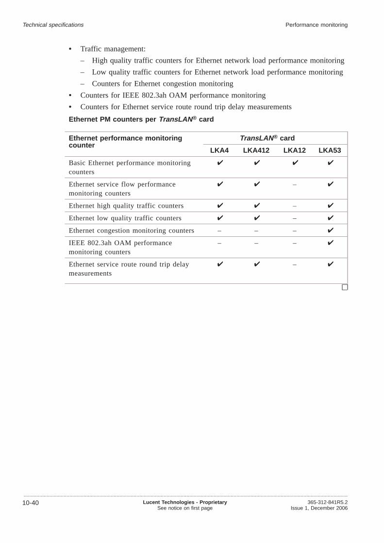
• Traffic management:
– High quality traffic counters for Ethernet network load performance monitoring
– Low quality traffic counters for Ethernet network load performance monitoring
– Counters for Ethernet congestion monitoring
• Counters for IEEE 802.3ah OAM performance monitoring
• Counters for Ethernet service route round trip delay measurements
Ethernet PM counters per TransLAN ® card
Ethernet performance monitoringcounter
TransLAN ® card
LKA4 LKA412 LKA12 LKA53
Basic Ethernet performance monitoringcounters
Ethernet service flow performancemonitoring counters
–
Ethernet high quality traffic counters –
Ethernet low quality traffic counters –
Ethernet congestion monitoring counters – – –
IEEE 802.3ah OAM performancemonitoring counters
– – –
Ethernet service route round trip delaymeasurements
–
Technical specifications Performance monitoring
...................................................................................................................................................................................................................................
10-40 Lucent Technologies - ProprietarySee notice on first page
365-312-841R5.2Issue 1, December 2006

Supervision and alarms...................................................................................................................................................................................................................................
Plug-in unit indication
LEDs
• LED continuously on diagnostic error
• LED flashing transmission signal error
• LED green activity continuously on (only on core units)
Ethernet electrical port LED indication
LED indicators
• Green: indicates the link status of a port
• Yellow: indicates the transmit and/or receive activity on a port.
Ethernet optical port LED indication (via SFP)
LED indicators
• Green LED: for Link status,
• Red: indicates the Fault status.
• Yellow: indicates the Activity status.
User panel
LED indicators:
• Power
• Prompt alarm
• Deferred alarm
• Info alarm
• Abnormal
• Suppressed (alarm cut-off)
• Station alarm disconnected
• Use CIT.
Push-buttons:
• Suppress (alarm cut-off)
• Disconnect station alarms.
Power unit
LED indicators
• Green feeder power
• Red central auxiliary supply failure.
Technical specifications
...................................................................................................................................................................................................................................365-312-841R5.2Issue 1, December 2006
Lucent Technologies - ProprietarySee notice on first page
10-41

Miscellaneous discretes
input/outputs
• 8 inputs
• 4 outputs
CIT
CIT connector F-interfaces V11/RS232
Access to embedded Data Communication Channels (DCC)
In-station Q-LAN interface, 10Base-T.
Technical specifications Supervision and alarms
...................................................................................................................................................................................................................................
10-42 Lucent Technologies - ProprietarySee notice on first page
365-312-841R5.2Issue 1, December 2006

Spare part information...................................................................................................................................................................................................................................
Recommended spare parts
The following tables indicate how many plug-in units, paddle boards and sub-racks arerequired for the customer’s substitution spare stocks, assumed a 14 days lead time(contract specific).. For more specific information please contact your LucentTechnologies local customer team.
The actual recommendable numbers can be calculated from the numbers below bymultiplying them with the ratio of the contractual lead time to these 14 days(conservative approach for times≥ 14 days)
Type 1 packused
up to 10packsused
up to100 packsused
up to1000packsused
up to10000packsused
FAN unit 1 1 2 4 13
Power unit 1 1 1 3 9
Misc. IO unit LEFT 1 1 1 2 4
Misc. IO unit RIGHT 1 1 1 2 5
System Controller Plus 1 1 2 5 20
STM-64 S64.2b/3b 1.5um CC-272/64 1 1 4 12 65
STM-64 L64.2b/3 1.5um CC-272/64 1 2 4 13 69
STM-64 VSR 1 1 3 11 59
STM-16 L16.1 1.3um CC-64/32 1 1 3 8 40
STM-16 L16.2 1.5um CC-64/32 1 1 3 8 40
1 x STM-16 L16.1 1.3um ITU 1 1 2 7 29
1 x STM-16 L16.2 1.5um ITU 1 1 2 7 29
1 x STM-4 S4.1 1.3um 1 1 2 4 16
1 x STM-4 L4.2 1.5um 1 1 2 5 20
4 x STM-1 S1.1 1.3um 1 1 2 6 23
4 x STM-1 L1.2 1.5um 1 1 2 7 31
4 x STM-1e 1 1 2 4 17
PB 4xSTM-1 Un-Protected 1 1 1 2 5
PB 4xSTM-1 (Prot.1+1) 1 1 1 3 8
Technical specifications
...................................................................................................................................................................................................................................365-312-841R5.2Issue 1, December 2006
Lucent Technologies - ProprietarySee notice on first page
10-43

Type 1 packused
up to 10packsused
up to100 packsused
up to1000packsused
up to10000packsused
12 x E3/DS3 (switchable) 1 1 3 7 35
Paddle Brd. 12 x E3/DS3 1 1 1 2 5
PB 12 x E3/DS3 (Prot.1+1) 1 1 1 3 11
63 x E1 1 1 2 6 24
PB 63x2Mb/s 75 1:N P./Un-Prot. 1 1 1 3 10
PB 63x2Mb/s 120 1:N P./Un-prot 1 1 1 3 10
63 x DS1 (1.5 Mbit/s) 1 1 2 5 18
PB 63x1.5Mb/s 100 Ohms P./Un-prot 1 1 1 3 8
2 x GbE 1 1 2 6 26
SX - module 1 1 1 3 8
LX - module 1 1 1 3 8
8 x E/FE 1 1 2 6 29
Paddle Brd. 8xLAN 100 Ohm 1 1 1 3 9
Release 5.1 recommended spare parts
The following table shows the recommended spare part numbers with respect to thenumber of circuit packs used, assuming a 10 days lead time:
Type Apparatus code up to 5packsused
up to10
packsused
up to50
packsused
up to100
packsused
up to500
packsused
up to1000
packsused
up to2000
packsused
STM-64 I64.1r 1.3umCC-272/128
LKA49 2 2 3 4 7 11 16
STM-64 V64.2 1.5umCC-272/128
LKA350 2 2 4 5 9 13 20
STM-64 L64.2b/3 1.5umCC-272/128
LKA28 2 2 4 4 9 13 20
STM-64 U64.2 1.5umCC-272/128
LKA281 2 3 4 5 9 11 15
STM-64 S64.2b/3b 1.5umCC-272/128
LKA29 2 2 4 4 9 13 19
4 x STM-16 SFPCC-272/128
LKA48 2 2 3 4 7 10 15
Technical specifications Spare part information
...................................................................................................................................................................................................................................
10-44 Lucent Technologies - ProprietarySee notice on first page
365-312-841R5.2Issue 1, December 2006

Type Apparatus code up to 5packsused
up to10
packsused
up to50
packsused
up to100
packsused
up to500
packsused
up to1000
packsused
up to2000
packsused
1 x STM-16 SFP CC-176/64 LKA481 2 2 3 4 7 10 15
1 x STM-16 VH CC-176/64OBA
LKA482 2 2 3 4 7 10 15
STM-1/ STM-4 main boardSFP
LKA39 2 2 3 3 5 6 9
1 x STM-16 SFP LKA50 2 2 2 3 4 6 7
PB 12 x STM-1eUn-protected
PBP5 2 2 2 3 4 5 6
PB 12 x STM-1e (Prot. 1+1) PBP6 2 2 2 3 4 5 7
PB 6 x STM-1o SFP PBP8 1 2 2 2 3 3 4
PB-E1/P75/63 PBE3D 2 2 2 2 4 4 4
PB 63x2Mb/s 120 1:NP./Un-prot
PBE41 1 1 2 2 4 4 5
PB OPT/12 SFP PBL12 2 2 2 2 3 4 5
PB OPT/12 SFP PBO12 2 2 2 2 4 4 6
IP-LAN/12 LKA412 2 2 3 4 6 9 12
2 x GbE-Full/ one slotsolution
LKA53 2 2 3 4 6 9 13
System Controller Enhanced LKA21 2 2 3 3 5 7 9
System Controller Enhanced LKA21B 2 2 3 3 6 8 11
SFP 2Km I-16 OM2G5-I16 1 2 2 2 3 4 4
SFP 40Km L-16.1 OM2G5-L16.1 2 2 2 2 3 4 4
SFP 80Km L-16.2/3 OM2G5-L16.2 2 2 2 2 3 4 4
SFP SH 15Km S-4.1 OM622M-S4.1 2 2 2 2 3 4 5
SFP LH 40Km L-4.1 OM622M-L4.1 2 2 2 2 3 4 4
SFP LH 80Km L-4.2 OM622M-L4.2 1 2 2 2 3 4 4
SFP SH 15Km S-1.1 OM155M-S1.1 1 2 2 2 3 4 4
SFP LH 40Km L-1.1 OM155M-L1.1 1 2 2 2 3 4 4
SFP LH 80Km L-1.2 OM155M-L1.2 1 2 2 2 3 4 4
SFP 80km, L-1.2, LR-2 OM155M-L1.2 1 1 2 2 4 4 5
SFP 80km, L-4.2, LR-2 OM622M-L4.2 1 1 2 2 4 4 5
SFP 40km, L-16.1, LR-1 OM2G5-L16.1 1 1 2 3 4 5 6
SFP 80km, L-16.2, LR-2 OM2G5-L16.2 1 1 2 3 5 5 6
STM-16 cWDM SFP color11 (1470nm) 80 km
OM16CL47 2 2 2 2 3 4 5
STM-16 cWDM SFP color12 (1490nm) 80 km
OM16CL49 2 2 2 2 3 4 5
Technical specifications Spare part information
...................................................................................................................................................................................................................................365-312-841R5.2Issue 1, December 2006
Lucent Technologies - ProprietarySee notice on first page
10-45
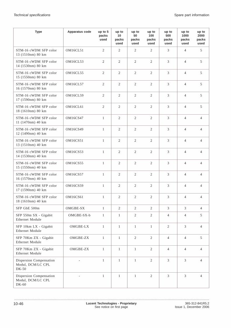
Type Apparatus code up to 5packsused
up to10
packsused
up to50
packsused
up to100
packsused
up to500
packsused
up to1000
packsused
up to2000
packsused
STM-16 cWDM SFP color13 (1510nm) 80 km
OM16CL51 2 2 2 2 3 4 5
STM-16 cWDM SFP color14 (1530nm) 80 km
OM16CL53 2 2 2 2 3 4 5
STM-16 cWDM SFP color15 (1550nm) 80 km
OM16CL55 2 2 2 2 3 4 5
STM-16 cWDM SFP color16 (1570nm) 80 km
OM16CL57 2 2 2 2 3 4 5
STM-16 cWDM SFP color17 (1590nm) 80 km
OM16CL59 2 2 2 2 3 4 5
STM-16 cWDM SFP color18 (1610nm) 80 km
OM16CL61 2 2 2 2 3 4 5
STM-16 cWDM SFP color11 (1470nm) 40 km
OM16CS47 1 2 2 2 3 4 4
STM-16 cWDM SFP color12 (1490nm) 40 km
OM16CS49 1 2 2 2 3 4 4
STM-16 cWDM SFP color13 (1510nm) 40 km
OM16CS51 1 2 2 2 3 4 4
STM-16 cWDM SFP color14 (1530nm) 40 km
OM16CS53 1 2 2 2 3 4 4
STM-16 cWDM SFP color15 (1550nm) 40 km
OM16CS55 1 2 2 2 3 4 4
STM-16 cWDM SFP color16 (1570nm) 40 km
OM16CS57 1 2 2 2 3 4 4
STM-16 cWDM SFP color17 (1590nm) 40 km
OM16CS59 1 2 2 2 3 4 4
STM-16 cWDM SFP color18 (1610nm) 40 km
OM16CS61 1 2 2 2 3 4 4
SFP GbE 500m OMGBE-SX 1 2 2 2 3 3 4
SFP 550m SX - GigabitEthernet Module
OMGBE-SX-b 1 1 2 2 4 4 5
SFP 10km LX - GigabitEthernet Module
OMGBE-LX 1 1 1 1 2 3 4
SFP 70Km ZX - GigabitEthernet Module
OMGBE-ZX 1 1 2 2 4 4 5
SFP 70Km ZX - GigabitEthernet Module
OMGBE-ZX 1 1 1 2 4 4 4
Dispersion CompensationModul, DCM/LC CPLDK-50
- 1 1 1 2 3 3 4
Dispersion CompensationModul, DCM/LC CPLDK-60
- 1 1 1 2 3 3 4
Technical specifications Spare part information
...................................................................................................................................................................................................................................
10-46 Lucent Technologies - ProprietarySee notice on first page
365-312-841R5.2Issue 1, December 2006

The following table shows the recommended spare part numbers with respect to thenumber of circuit packs used, assuming a 20 days lead time:
Type Apparatus code up to 5packsused
up to10
packsused
up to50
packsused
up to100packs
used
up to500
packsused
up to1000
packsused
up to2000
packsused
STM-64 I64.1r 1.3umCC-272/128
LKA49 2 3 4 5 11 16 25
STM-64 V64.2 1.5umCC-272/128
LKA350 2 3 5 6 13 20 33
STM-64 L64.2b/3 1.5umCC-272/128
LKA28 2 3 4 6 13 20 32
STM-64 U64.2 1.5umCC-272/128
LKA281 3 4 5 6 12 15 21
STM-64 S64.2b/3b 1.5umCC-272/128
LKA29 2 3 4 6 13 19 31
4 x STM-16 SFP CC-272/128 LKA48 2 3 4 5 10 15 24
1 x STM-16 SFP CC-176/64 LKA481 2 3 4 5 9 14 21
1 x STM-16 VH CC-176/64OBA
LKA482 2 3 4 5 10 15 23
STM-1/ STM-4 main boardSFP
LKA39 2 2 3 4 6 9 13
1 x STM-16 SFP LKA50 2 2 3 3 6 7 11
PB 12 x STM-1eUn-protected
PBP5 2 2 3 3 5 6 9
PB 12 x STM-1e (Prot. 1+1) PBP6 2 2 3 3 5 7 10
PB 6 x STM-1o SFP PBP8 2 2 2 2 3 4 5
PB-E1/P75/63 PBE3D 2 2 2 2 4 4 6
PB OPT/12 SFP PBL12 2 2 2 3 4 5 6
PB OPT/12 SFP PBO12 2 2 2 3 4 6 8
PB 63x2Mb/s 120 1:NP./Un-prot
PBE41 1 1 2 3 5 5 7
IP-LAN/12 LKA412 2 2 4 4 9 12 19
2 x GbE-Full/ one slotsolution
LKA53 2 2 4 5 9 13 20
System Controller Enhanced LKA21 2 2 3 4 7 9 14
SFP 2Km I-16 OM2G5-I16 2 2 2 2 4 4 6
SFP 40Km L-16.1 OM2G5-L16.1 2 2 2 2 4 4 6
SFP 40km, L-16.1, LR-1 OM2G5-L16.1 1 2 3 4 5 6 8
SFP 80Km L-16.2/3 OM2G5-L16.2 2 2 2 2 4 4 6
SFP 80km, L-16.2, LR-2 OM2G5-L16.2 1 2 3 4 6 6 8
SFP SH 15Km S-4.1 OM622M-S4.1 2 2 2 3 4 5 7
SFP LH 40Km L-4.1 OM622M-L4.1 2 2 2 2 4 4 6
Technical specifications Spare part information
...................................................................................................................................................................................................................................365-312-841R5.2Issue 1, December 2006
Lucent Technologies - ProprietarySee notice on first page
10-47

Type Apparatus code up to 5packsused
up to10
packsused
up to50
packsused
up to100packs
used
up to500
packsused
up to1000
packsused
up to2000
packsused
SFP LH 80Km L-4.2 OM622M-L4.2 2 2 2 2 4 4 6
SFP 80km, L-4.2, LR-2 OM622M-L4.2 1 1 2 3 4 5 6
SFP SH 15Km S-1.1 OM155M-S1.1 2 2 2 2 4 4 6
SFP LH 40Km L-1.1 OM155M-L1.1 2 2 2 2 4 4 6
SFP LH 80Km L-1.2 OM155M-L1.2 2 2 2 2 4 4 6
SFP 80km, L-1.2, LR-2 OM155M-L1.2 1 1 2 3 4 5 6
STM-16 cWDM SFP color 11(1470nm) 80 km
OM16CL47 2 2 2 3 4 5 7
STM-16 cWDM SFP color12 (1490nm) 80 km
OM16CL49 2 2 2 3 4 5 7
STM-16 cWDM SFP color13 (1510nm) 80 km
OM16CL51 2 2 2 3 4 5 7
STM-16 cWDM SFP color14 (1530nm) 80 km
OM16CL53 2 2 2 3 4 5 7
STM-16 cWDM SFP color15 (1550nm) 80 km
OM16CL55 2 2 2 3 4 5 7
STM-16 cWDM SFP color16 (1570nm) 80 km
OM16CL57 2 2 2 3 4 5 7
STM-16 cWDM SFP color17 (1590nm) 80 km
OM16CL59 2 2 2 3 4 5 7
STM-16 cWDM SFP color18 (1610nm) 80 km
OM16CL61 2 2 2 3 4 5 7
STM-16 cWDM SFP color 11(1470nm) 40 km
OM16CS47 2 2 2 2 4 4 6
STM-16 cWDM SFP color12 (1490nm) 40 km
OM16CS49 2 2 2 2 4 4 6
STM-16 cWDM SFP color13 (1510nm) 40 km
OM16CS51 2 2 2 2 4 4 6
STM-16 cWDM SFP color14 (1530nm) 40 km
OM16CS53 2 2 2 2 4 4 6
STM-16 cWDM SFP color15 (1550nm) 40 km
OM16CS55 2 2 2 2 4 4 6
STM-16 cWDM SFP color16 (1570nm) 40 km
OM16CS57 2 2 2 2 4 4 6
STM-16 cWDM SFP color17 (1590nm) 40 km
OM16CS59 2 2 2 2 4 4 6
STM-16 cWDM SFP color18 (1610nm) 40 km
OM16CS61 2 2 2 2 4 4 6
SFP GbE 500m OMGBE-SX 2 2 2 2 3 4 5
SFP 550m SX - GigabitEthernet Module
OMGBE-SX-b 1 1 2 3 5 5 6
SFP GbE 5km OMGBE-LX 2 2 2 3 4 6 8
Technical specifications Spare part information
...................................................................................................................................................................................................................................
10-48 Lucent Technologies - ProprietarySee notice on first page
365-312-841R5.2Issue 1, December 2006

Type Apparatus code up to 5packsused
up to10
packsused
up to50
packsused
up to100packs
used
up to500
packsused
up to1000
packsused
up to2000
packsused
SFP 10km LX - GigabitEthernet Module
OMGBE-LX 1 1 1 2 3 4 4
SFP 70Km ZX - GigabitEthernet Module
OMGBE-ZX 1 1 2 3 5 5 6
SFP 70Km ZX - GigabitEthernet Module
OMGBE-ZX 1 1 2 2 4 4 5
Dispersion CompensationModul, DCM/LC CPL DK-50
- 1 1 2 2 4 4 5
Dispersion CompensationModul, DCM/LC CPL DK-60
- 1 1 2 2 4 4 5
Technical specifications Spare part information
...................................................................................................................................................................................................................................365-312-841R5.2Issue 1, December 2006
Lucent Technologies - ProprietarySee notice on first page
10-49


Appendix A: An SDH overview
Overview...................................................................................................................................................................................................................................
Purpose
This chapter briefly describes the Synchronous Digital Hierarchy (SDH).
Synchronous Digital Hierarchy
In 1988, the ITU-T (formerly CCITT) came to an agreement on the SynchronousDigital Hierarchy (SDH). The corresponding ITU-T Recommendation G.707 forms thebasis of a global, uniform optical transmission network. SDH can operate withplesiochronous networks and therefore allows the continuous evolution of existingdigital transmission networks.
The major features and advantages of SDH are:
• Compatibility of transmission equipment and networks on a worldwide basis
• Uniform physical interfaces
• Easy cross connection of signals in the network nodes
• Possibility of transmitting PDH (Plesiochronous Digital Hierarchy) tributary signalsat bit rates commonly used at present
• Simple adding and dropping of individual channels without special multiplexers(add/drop facility)
• Easy transition to higher transmission rates
• Due to the standardization of the network element functions SDH supports asuperordinate network management and new monitoring functions and providestransport capacity and protocols (Telecommunication Management Network, TMN)for this purpose in the overheads of the multiplex signals.
• High flexibility and user-friendly monitoring possibilities, e.g. end-to-endmonitoring of the bit error ratio.
Purpose of SDH
The basic purpose of SDH is to provide a standard synchronous optical hierarchy withsufficient flexibility to accommodate digital signals that currently exist in today’snetwork, as well as those planned for the future.
....................................................................................................................................................................................................................................365-312-841R5.2Issue 1, December 2006
Lucent Technologies - ProprietarySee notice on first page
A-1

SDH currently defines standard rates and formats and optical interfaces. Today,mid-span meet is possible at the optical transmission level. These and other relatedissues continue to evolve through the ITU-T committees.
ITU-T addressed issues
The set of ITU-T Recommendations defines
• Optical parameters
• Multiplexing schemes to map existing digital signals (PDH) into SDH payloadsignals
• Overhead channels to support standard operation, administration, maintenance, andprovisioning (OAM&P) functions
• Criteria for optical line Automatic Protection Switch (APS)
References
For more detailed information on SDH, refer to
• ITU-T Recommendation G.703, “Physical/electrical characteristics of hierarchicaldigital interfaces”, October 1996
• ITU-T Recommendation G.707, “Network Node Interface For The SynchronousDigital Hierarchy (SDH)”, March 1996
• ITU-T Recommendation G.780, “Vocabulary of terms for synchronous digitalhierarchy (SDH) networks and equipment“ , November 1993
• ITU-T Recommendation G.783, “Characteristics of Synchronous Digital Hierarchy(SDH) Multiplexing Equipment Functional Blocks “, April 1997
• ITU-T Recommendation G.784, “Synchronous Digital Hierarchy (SDH)Management “, January 1994
• ITU-T Recommendation G.785, “Characteristics of a flexible multiplexer in asynchronous digital hierarchy environment “, November 1996
• ITU-T Recommendation G.813, “Timing characteristics of SDH equipment slaveclocks (SEC)“, August 1996
• ITU-T Recommendation G.823, “The control of jitter and wander within digitalnetworks which are based on the 2048-kbit/s hierarchy“, March 1993
• ITU-T Recommendation G.825, “The control of jitter and wander within digitalnetworks which are based on the synchronous digital hierarchy (SDH)“, March1993
• ITU-T Recommendation G.826, “ Error performance Parameters and Objectives forInternational, Constant Bit Rate Digital Paths at or Above the Primary Rate”,February 1999
• ITU-T Recommendation G.957, “Optical interfaces for equipments and systemsrelating to the synchronous digital hierarchy“, July 1995
An SDH overview Overview
...................................................................................................................................................................................................................................
A-2 Lucent Technologies - ProprietarySee notice on first page
365-312-841R5.2Issue 1, December 2006

Contents
SDH signal hierarchy A-4
SDH path and line sections A-6
SDH frame structure A-9
SDH digital multiplexing A-11
SDH interface A-13
SDH multiplexing process A-14
SDH demultiplexing process A-15
SDH transport rates A-16
An SDH overview Overview
...................................................................................................................................................................................................................................365-312-841R5.2Issue 1, December 2006
Lucent Technologies - ProprietarySee notice on first page
A-3

SDH signal hierarchy...................................................................................................................................................................................................................................
This section describes the basics of the SDH hierarchy.
STM-1 Frame
The SDH signal hierarchy is based on a basic “building block” frame called theSynchronous Transport Module 1 (STM-1), as shown in“SDH STM-1 frame” (p. A-5).
The STM-1 frame has a rate of 8000 frames per second and a duration of 125microseconds
The STM-1 frame consists of 270 columns and 9 rows.
Each cell in the matrix represents an 8-bit byte.
Transmitting Signals
The STM-1 frame (STM = Synchronous Transport Module) is transmitted seriallystarting from the left with row 1 column 1 through column 270, then row 2 column 1through 270, continuing on, row-by-row, until all 2430 bytes (9x270) of the STM-1frame have been transmitted. Because each STM-1 frame consists of 2430 bytes andeach byte has 8 bits, the frame contains 19440 bits a frame. There are 8000 STM-1frames a second, at the STM-1 signal rate of 155.520.000 (19440 x 8000) kbit/s.
Three higher bit rates are also defined:
• 622.080 Mbit/s (STM-4)
• 2488.320 Mbit/s (STM-16)
• 9953.280 Mbit/s (STM-64)
• 39813.120 Mbit/s (STM-256)
The bit rates of the higher order hierarchy levels are integer multiples of the STM-1transmission rate.
An SDH overview
...................................................................................................................................................................................................................................
A-4 Lucent Technologies - ProprietarySee notice on first page
365-312-841R5.2Issue 1, December 2006

SDH STM-1 frame
Section overhead (SOH)
The first nine bytes of each row with exception of the fourth row are part of the SOH(Section OverHead). The first nine byte of the fourth row contain the AU pointer (AU= Administrative Unit).
STM-1 payload
Columns 10 through 270 (the remainder of the frame), are reserved for payloadsignals.
An SDH overview SDH signal hierarchy
...................................................................................................................................................................................................................................365-312-841R5.2Issue 1, December 2006
Lucent Technologies - ProprietarySee notice on first page
A-5

SDH path and line sections...................................................................................................................................................................................................................................
This section describes and illustrates the SDH path and line sections.
SDH layers
SDH divides its processing functions into the following three path and line sections:
• Regenerator section
• Multiplex section
• Path
These three path and line sections are associated with
• Equipment that reflects the natural divisions in network spans
• Overhead bytes that carry information used by various network elements
Equipment layers
The following table lists and defines each SDH equipment path and line section.
Path and linesections
Definition
Regenerator section A regenerator section describes the section between two networkelements. The network elements, however, do not necessarilyhave to be regenerators.
Multiplex section A multiplex section is the section between two multiplexers. Amultiplex section is defined as that part of a path where nomultiplexing or demultiplexing of the STM-N frame takes place.
Path A path is the logical signal connection between two terminationpoints.
A path can be composed of a number of multiplex sectionswhich themselves can consist of several regenerator sections.
Path, MS and RS
The following figure illustrates the equipment path, multiplex sections and regeneratorsections in a signal path.
An SDH overview
...................................................................................................................................................................................................................................
A-6 Lucent Technologies - ProprietarySee notice on first page
365-312-841R5.2Issue 1, December 2006
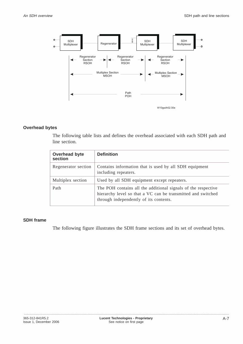
Overhead bytes
The following table lists and defines the overhead associated with each SDH path andline section.
Overhead bytesection
Definition
Regenerator section Contains information that is used by all SDH equipmentincluding repeaters.
Multiplex section Used by all SDH equipment except repeaters.
Path The POH contains all the additional signals of the respectivehierarchy level so that a VC can be transmitted and switchedthrough independently of its contents.
SDH frame
The following figure illustrates the SDH frame sections and its set of overhead bytes.
An SDH overview SDH path and line sections
...................................................................................................................................................................................................................................365-312-841R5.2Issue 1, December 2006
Lucent Technologies - ProprietarySee notice on first page
A-7

An SDH overview SDH path and line sections
...................................................................................................................................................................................................................................
A-8 Lucent Technologies - ProprietarySee notice on first page
365-312-841R5.2Issue 1, December 2006

SDH frame structure...................................................................................................................................................................................................................................
This section provides detailed information on the locations and functions of variousoverhead bytes for each of the following SDH path and line sections:
• Regenerator Section
• Multiplex Section
• Path
Section overhead
The following table identifies the location and function of each regenerator sectionoverhead byte.
Bytes Function
A1, A2 Frame alignment A1 =1111 0110 ; A2 =0010 1000 ; Thesefixed-value bytes are used for synchronization.
B1 BIP-8 parity test
Regenerator section error monitoring; BIP-8 :
Computed over all bits of the previous frame after scrambling; B1 isplaced into the SOH before scrambling;
BIP-X: (Bit Interleaved Parity X bits) Even parity, X-bit code;
first bit of code = even parity over first bit of all X-bit sequences;
B2 Multiplex section error monitoring; BIP-24 :
B2 is computed over all bits of the previous STM-1 frame except forrow 1 to 3 of the SOH (RSOH); B2 is computed after and placedbefore scrambling;
Z0 Spare bytes
D1 - D3 (=DCCR) D4 -D12 (= DCCM)
Data Communication Channel (network management informationexchange)
E1 Orderwire channel
E2 Orderwire channel
F1 User channel
K1, K2 Automatic protection switch
K2 MS-AIS/RDI indicator
S1 Synchronization Status Message
M1 REI (Remote Error Indication) byte
NU National Usage
An SDH overview
...................................................................................................................................................................................................................................365-312-841R5.2Issue 1, December 2006
Lucent Technologies - ProprietarySee notice on first page
A-9
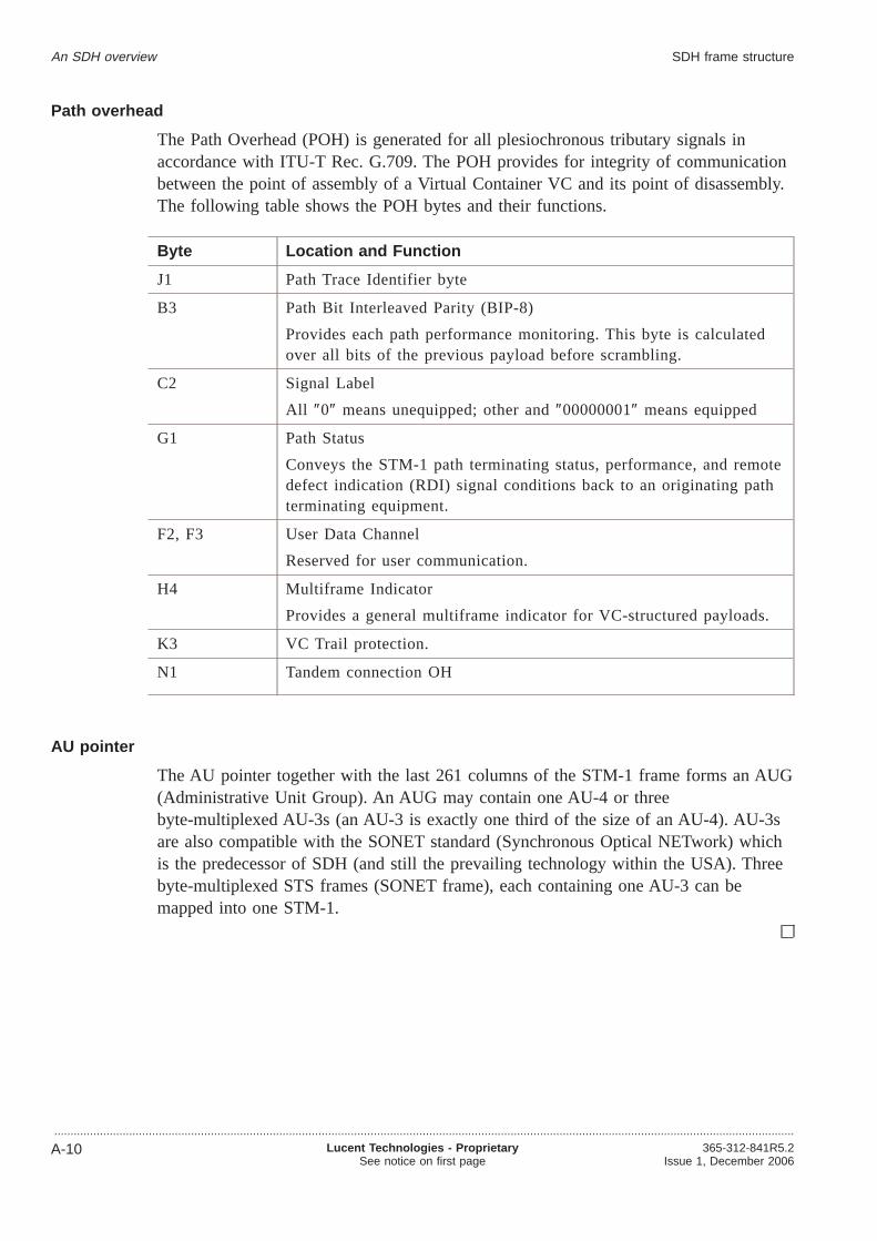
Path overhead
The Path Overhead (POH) is generated for all plesiochronous tributary signals inaccordance with ITU-T Rec. G.709. The POH provides for integrity of communicationbetween the point of assembly of a Virtual Container VC and its point of disassembly.The following table shows the POH bytes and their functions.
Byte Location and Function
J1 Path Trace Identifier byte
B3 Path Bit Interleaved Parity (BIP-8)
Provides each path performance monitoring. This byte is calculatedover all bits of the previous payload before scrambling.
C2 Signal Label
All ″0″ means unequipped; other and″00000001″ means equipped
G1 Path Status
Conveys the STM-1 path terminating status, performance, and remotedefect indication (RDI) signal conditions back to an originating pathterminating equipment.
F2, F3 User Data Channel
Reserved for user communication.
H4 Multiframe Indicator
Provides a general multiframe indicator for VC-structured payloads.
K3 VC Trail protection.
N1 Tandem connection OH
AU pointer
The AU pointer together with the last 261 columns of the STM-1 frame forms an AUG(Administrative Unit Group). An AUG may contain one AU-4 or threebyte-multiplexed AU-3s (an AU-3 is exactly one third of the size of an AU-4). AU-3sare also compatible with the SONET standard (Synchronous Optical NETwork) whichis the predecessor of SDH (and still the prevailing technology within the USA). Threebyte-multiplexed STS frames (SONET frame), each containing one AU-3 can bemapped into one STM-1.
An SDH overview SDH frame structure
...................................................................................................................................................................................................................................
A-10 Lucent Technologies - ProprietarySee notice on first page
365-312-841R5.2Issue 1, December 2006

SDH digital multiplexing...................................................................................................................................................................................................................................
Digital multiplexing is SDH’s method of byte mapping tributary signals to a highersignal rate, which permits economical extraction of a single tributary signal without theneed to demultiplex the entire STM-1 payload. In addition, SDH provides overheadchannels for use by OAM&P groups.
SDH digital multiplexing
The following figure illustrates the SDH technique of mapping tributary signals intothe STM frames.
Transporting SDH payloads
Tributary signals are mapped into a digital signal called a virtual container (VC). TheVC is a structure designed for the transport and switching of STM payloads. There arevarious sizes of VCs: VC-11, VC-12, VC-2, VC-3, VC-4, VC-4-4C, VC-4-16C,VC-4-64C and VC-4-256C.
C-11
C-12
C-2
C-3STM-0
C-4
C-4-4C
C-4-16C
C-4-64C
C-4-256C
STM-1
STM-4
STM-16
STM-64
STM-256
VC-11
VC-12
VC-2
VC-3
VC-3
Pointer processing
Multiplexing
Aligning
Mapping
AU-3
…
VC-4
VC-4-4C
VC-4-16C
VC-4-64C
VC-4-256C
AU-4
AU-4-4C
AU-4-16C
AU-4-64C
AU-4-256C
TU-11
1
1
1
1
1
1
1
1
1
1
1
1
1
3
3
3
4
4
4
4
4
7
7
TU-12
TU-2
TU-3
TUG-2
TUG-3
AUG-1
AUG-4
AUG-16
AUG-64
AUG-256
An SDH overview
...................................................................................................................................................................................................................................365-312-841R5.2Issue 1, December 2006
Lucent Technologies - ProprietarySee notice on first page
A-11

Table
The following table shows the mapping possibilities of some digital signals into SDHpayloads.
Input tributary Voice Channels Rate Mapped Into
1.5 Mbit/s 24 1.544 Mbit/s VC-11
2 Mbit/s 32 2.048 Mbit/s VC-12
6 Mbit/s 96 6.312 Mbit/s VC-2
34 Mbit/s 672 34.368 Mbit/s VC-3
45 Mbit/s 672 44.736 Mbit/s VC-3
140 Mbit/s 2016 139.264 Mbit/s VC-4
An SDH overview SDH digital multiplexing
...................................................................................................................................................................................................................................
A-12 Lucent Technologies - ProprietarySee notice on first page
365-312-841R5.2Issue 1, December 2006

SDH interface...................................................................................................................................................................................................................................
This section describes the SDH interface.
Description
The SDH interface provides the optical mid-span meet between SDH networkelements. An SDH network element is the hardware and software that affects thetermination or repeating of an SDH standard signal.
SDH interface
An SDH overview
...................................................................................................................................................................................................................................365-312-841R5.2Issue 1, December 2006
Lucent Technologies - ProprietarySee notice on first page
A-13

SDH multiplexing process...................................................................................................................................................................................................................................
SDH provides for multiplexing of 2-Mbit/s (C-12) and 34-Mbit/s (C-3) signals into anSTM-1 frame.
Furthermore, multiplexing paths also exist for the SONET specific 1.5-Mbit/s, 6-Mbit/sand 45-Mbit/s signals.
Process
The following describes the process for multiplexing a 2-Mbit/s signal. The“SDHdigital multiplexing” (p. A-11)illustrates the multiplexing process.
...................................................................................................................................................................................................
1 Input 2-Mbit/s tributary is mapped
• Each VC-12 carries a single 2-Mbit/s payload.
• The VC-12 is aligned into a Tributary Unit TU-2 using a TU pointer.
• Three TU-2 are then multiplexed into a Tributary Unit Group TUG-2.
• Seven TUG-2 are multiplexed into an TUG-3.
• Three TUG-3 are multiplexed into an VC-4.
• The VC-4 is aligned into an Administrative Unit AU-4 using a AU pointer.
• The AU-4 is mapped into an AUG which is then mapped into an STM-1 frame.
...................................................................................................................................................................................................
2 After VCs are multiplexed into the STM-1 payload, the section overhead is added.
...................................................................................................................................................................................................
3 Scrambled STM-1 signal is transported to the optical stage.
An SDH overview
...................................................................................................................................................................................................................................
A-14 Lucent Technologies - ProprietarySee notice on first page
365-312-841R5.2Issue 1, December 2006

SDH demultiplexing process...................................................................................................................................................................................................................................
Demultiplexing is the inverse of multiplexing. This topic describes how to demultiplexa signal.
Process
The following describes the process for demultiplexing an STM-1 signal to a 2 Mbit/ssignal. The“SDH digital multiplexing” (p. A-11)illustrates the demultiplexing process.
...................................................................................................................................................................................................
1 The unscrambled STM-1 signal from the optical conversion stages is processed toextract the path overhead and accurately locate the payload.
...................................................................................................................................................................................................
2 The STM-1 path overhead is processed to locate the VCs. The individual VCs are thenprocessed to extract VC overhead and, via the VC pointer, accurately locate the2-Mbit/s signal.
...................................................................................................................................................................................................
3 The 2-Mbit/s signal is desynchronized, providing a standard 2-Mbit/s signal to theasynchronous network.
Key points
SDH STM pointers are used to locate the payload relative to the transport overhead.
Remember the following key points about signal demultiplexing:
• The SDH frame is a fixed time (125 µs) and no bit-stuffing is used.
• The synchronous payload can float within the frame. This is to permitcompensation for small variations in frequency between the clocks of the twosystems that may occur if the systems are independently timed (plesiochronoustiming).
An SDH overview
...................................................................................................................................................................................................................................365-312-841R5.2Issue 1, December 2006
Lucent Technologies - ProprietarySee notice on first page
A-15

SDH transport rates...................................................................................................................................................................................................................................
Higher rate STM-N frames are built through byte-multiplexing of N STM-1 signals.
Creating higher rate signals
A STM-N signal can only be multiplexed out of N STM-1 frames with their first A1byte at the same position (i.e. the first A1 byte arriving at the same time).
STM-N frames are built through byte-multiplexing of N STM-1 signals. Not all bytesof the multiplexed SOH (size= N x SOH of STM-1) are relevant in an STM-4/16.
For example there is only one B1 byte in an STM-4/16 frame which is computed thesame way as for an STM-1. Generally the SOH of the first STM-1 inside the STM-Nis used for SOH bytes that are needed only once. The valid bytes are given in ITU-TG.707.
SDH transport rates
Designation Line rate (Mbit/s) Capacity
STM-1 155.520 1 AU-4 or 3 AU-3
STM-4 622.080 4 AU-4 or 12 AU-3
STM-16 2488.320 16 AU-4 or 48 AU-3
STM-64 9953.280 64 AU-4 or 192 AU-3
STM-256 39813.120 256 AU-4 or 768 AU-3
An SDH overview
...................................................................................................................................................................................................................................
A-16 Lucent Technologies - ProprietarySee notice on first page
365-312-841R5.2Issue 1, December 2006

Glossary
....................................................................................................................................................................................................................................
Numerics
5ESSNumber 5 Electronic Switching System
5TADFive Tributary Add-Drop subrack
9TADNine Tributary Add-Drop subrack
12 digit Numerical Code (12NC)Used to as the unique identifier of an item or product. The first ten digits identify anitem. The eleventh digit specifies the particular variant of the item. The twelfth digitindicates the revision issue. Items for which the first eleven digitsare the same arefunctionally equal and may be exchanged.
....................................................................................................................................................................................................................................
A AAUAlarm Adapter Unit. Radio Relay circuit pack that is used for the collection of externalalarms and remote control of external equipment.
ACAlternating Current
ACUAlarm Collection Unit. Radio Relay circuit pack that collects of equipment alarms,analogue measurements from internal monitoring points and calculation data.
ADMAdd-Drop Multiplexer
Administrative Unit (AU)Carrier for TUs
Administrative-Unit Pointer (AU PTR)Indicates the phase alignment of the VC-n with respect to the STM-N frame. The pointerposition is fixed with respect to the STM-N frame.
....................................................................................................................................................................................................................................365-312-841R5.2Issue 1, December 2006
Lucent Technologies - ProprietarySee notice on first page
GL-1

AdministratorSee System Administrator.
AgentPerforms operations on managed objects and issues events on behalf of these managedobjects. All SDH managed objects will support at least one agent. Control of distantagents is possible via local “Managers”.
AlarmThe notification (audible or visual) of a significant event. See also Event.
Alarm Indication Signal (AIS)Code transmitted downstream in a digital Network that shows that an upstream failurehas been detected and also alarmed if the upstream alarm has not been suppressed. Alsocalled to as All OneS.
Alarm SeverityAn attribute that defines the priority of the alarm message. The way in which alarms areprocessed depends on the severity.
AligningUsing a pointer to indicate the head of a virtual container, e.g. to create anAdministrative Unit (AU) or a Tributary Unit (TU).
ALSAutomatic Laser Shutdown
Alternate Mark Inversion (AMI)A line code that employs a ternary signal to convert binary digits. In this line codesuccessive binary ones are represented by signal elements that are normally ofalternately positive and negative polarity but are equal in amplitude, binary zeros arerepresented by signal elements that have zero amplitude.
American Standard Code for Information Interchange (ASCII)A standard 8-bit code that is used to exchange information among data processingsystems and associated equipment.
AnomalyA difference between the actual and the desired operation of a function.
ANSIAmerican National Standards Institute
APSAutomatic Protection Switching
ASAlarm Suppression assembly
AssemblyGathering together of payload data with overhead and pointer information (an indicationof the direction of the signal).
Glossary
...................................................................................................................................................................................................................................
GL-2 Lucent Technologies - ProprietarySee notice on first page
365-312-841R5.2Issue 1, December 2006

AssociationA logical connection between manager and agent through which management informationcan be exchanged.
AsynchronousSee Non-synchronous.
ATCAuxiliary Transmission Channel
ATMAsynchronous Transfer Mode
ATPCAutomatic Transmit-Power Control
AUAdministrative Unit
AU4ADAdministrative Unit 4 Assembler/Disassembler
AUGAdministrative Unit Group
AUTOAutomatic
Automatic Transmit Power Control (ATPC)Reduces the power output from the transmitter during normal propagation conditions andincreases the power output to maximum during fading periods to try to maintain thenominal level of receiver input.
....................................................................................................................................................................................................................................
B B3ZSBipolar 3-Zero Substitution
B8ZSBipolar 8-Zero Substitution
BBTRBackplane Bus TRansceiver
BCBoard Controller
BCCBoard Controller Complex
BINBINary
Glossary
...................................................................................................................................................................................................................................365-312-841R5.2Issue 1, December 2006
Lucent Technologies - ProprietarySee notice on first page
GL-3

BIPBit-Interleaved Parity
BISDNBroadband Integrated Services Digital Network
Bit Error Ratio (BER)The ratio of bits received in error to bits sent.
Bit Interleaved Parity (BIP)A method of error monitoring that uses a specified number of bits (BIP-8)
BLD OUT LGBuild-Out Lightguide
Board Controller Local Area Network (BC-LAN)The internal local area network that provides communications between the LineController circuit pack and board controllers on the circuit packs that are associated witha high-speed line.
BOLBeginning Of Life
BranchingInterconnection of independent line systems.
Broadband CommunicationVoice, data, and/or video communication at greater than 2 Mbit/s rates.
Broadband Service TransportSTM-1 concatenation transport over the SLM for ATM applications.
BUSTRBUS Transmitter and Receiver
....................................................................................................................................................................................................................................
C CASChannel Associated Signaling
CATCATastrophic
CCCross-Connection, Cross-Connect
CCIRSee ITU-R.
CCITTSee ITU-T.
Glossary
...................................................................................................................................................................................................................................
GL-4 Lucent Technologies - ProprietarySee notice on first page
365-312-841R5.2Issue 1, December 2006

CCSCommon Channel Signaling
CEPTConférence Européenne des Administrations des Postes et des Télécommunications
ChannelA sub-unit of transmission capacity within a defined higher level of transmissioncapacity, e.g. a CEPT-4 (140 Mbit/s) within a 565 Mbit fiber system.
CIRCommitted Information Rate
CircuitA combination of two transmission channels that permits bidirectional transmission ofsignals between two points to support a single communication.
CITCraft Interface Terminal
Clear Channel (Cl. Ch.)A provisionable mode for the 34 and 140 Mbit/s tributary outputs that causes parityviolations not to be monitored or corrected before the 34 and 140 Mbit/s outputs areencoded.
ClientComputer in a computer network that generally offers a user interface to a server. Seealso Server.
CMICoded Mark Inversion
COCentral Office
Co-residentA hardware configuration where the OMS and ITM-NM applications can beindependently active at the same time on the same hardware and software platformwithout interfering with each other’s functioning.
Common Object Request Broker Architecture (CORBA)CORBA allows applications to communicate with one another no matter where they arelocated or who has designed them.
ConcatenationA procedure whereby a multiplicity of Virtual Containers are associated with each otherwith the result that their combined capacity can be used as a single container acrosswhich bit-sequence integrity is maintained.
CONN PCBConnector Printed Circuit Board
Glossary
...................................................................................................................................................................................................................................365-312-841R5.2Issue 1, December 2006
Lucent Technologies - ProprietarySee notice on first page
GL-5

Container (C)Carries plesiochronous signal, the “payload”.
CPCircuit Pack
Craft Interface Terminal (CIT)Local manager for SDH network elements.
CRCCyclic Redundancy Check
Cross-Connect MapConnection map for an SDH network element; contains information about how signalsare connected between high speed time slots and low speed tributaries. See also SquelchMap.
Cross-Polarization Interference CancellationThis feature permits both orthogonal polarizations of one Radio Frequency carrier to beused simultaneously, which provides greater spectral efficiency.
CTPConnection Termination Point
CVCode Violation
....................................................................................................................................................................................................................................
D DACSDigital Access & Cross-connect System
DACScan-TSee Integrated Transport Management Network Manager.
Data Communication Channel (DCC)The embedded overhead communication channel in the SDH line. The DCC is used forend-to-end communication and maintenance. It carries alarm, control, and statusinformation between network elements in an SDH network.
Data Communication Equipment (DCE)Provides the signal conversion and coding between the data terminating equipment andthe line. The DCE may be separate equipment or a part of the data terminatingequipment.
Data Terminating Equipment (DTE)Originates data for transmission and accepts transmitted data.
Database AdministratorA user who administers the database of the OMS application. See also User Privilege.
DCDirect Current
Glossary
...................................................................................................................................................................................................................................
GL-6 Lucent Technologies - ProprietarySee notice on first page
365-312-841R5.2Issue 1, December 2006

DCFData Communications Function
DCNData Communications Network
DCSDigital Cross-connect System
DDFDigital Distribution Frame
Dedicated Protection Ring (DP-Ring)A protection method used in some network elements.
Default Value ProvisioningThe original values are preprogrammed at the factory. These values can be overriddenusing local or remote provisioning.
DefectA limited interruption of the ability of an item to perform a required function. Thedefect may or may not lead to maintenance action this depends on the results ofadditional analysis.
DemultiplexingA process applied to a multiplexed signal to recover signals combined within it andrestore the distinct individual channels of these signals.
Digital LinkA transmission span such as a point-to-point 2 Mbit/s, 34 Mbit/s, 140 Mbit/s, VC12,VC3 or VC4 link between controlled network elements. The channels within a digitallink are insignificant.
Digital SectionA transmission span such as an STM-N or 565 Mbit/s signal. A digital section maycontain multiple digital channels.
DILDual In Line
Directory-Service Network Element (DSNE)A designated network element that is responsible for administering a database that mapsnetwork element names (node names) to addresses (node Id). There can be one DSNEper (sub)network.
DisassemblySplitting up of a signal into its constituents as payload data and overhead (an indicationof the direction of a signal).
DownstreamAt or towards the destination of the considered transmission stream, i.e. in the directionof transmission.
Glossary
...................................................................................................................................................................................................................................365-312-841R5.2Issue 1, December 2006
Lucent Technologies - ProprietarySee notice on first page
GL-7

DPLLDigital Phase-Locked Loop
DPSData communication Packet Switch
DRDigital Radio
DRIDual-Ring Interworking
DS-nDigital Signal, Level n
DTMFDual-Tone Multi-Frequency
Dual HomingAn STM-1/STM-4 ring with AM-1 Plus equipment can be dual homed on a ringconsisting ofMetropolis® ADM (Universal shelf), Metropolis® ADM (Compact shelf) orWaveStar® ADM 16/1. Also STM-16 rings can be dual homed with theMetropolis®
ADM (Universal shelf)).
Dual-Node InterworkingDual Node Interworking (DNI) is a configuration of two ring networks that share twocommon nodes. DNI allows a circuit with one termination in one ring and onetermination in another ring to survive a loss-of-signal failure of the shared node that iscurrently carrying service for the circuit.
DUSDo not Use for Synchronization
DWDMDense-Wavelength Division Multiplexing
....................................................................................................................................................................................................................................
E EC-nElectrical Carrier, Level n
ECCEmbedded Control Channel
EDFEEthernet Dropped Frames Errors
EH&SEnvironmental Health and Safety
EINBEthernet Incoming Number of Mbytes
Glossary
...................................................................................................................................................................................................................................
GL-8 Lucent Technologies - ProprietarySee notice on first page
365-312-841R5.2Issue 1, December 2006

Electronic Industries Association (EIA)A trade association of the electronic industry that establishes electrical and functionalstandards.
Element Management System (EMS)See Integrated Transport Management Subnetwork Controller.
EMCElectroMagnetic Compatibility
EMIElectroMagnetic Interference
EOLEnd Of Life
EONBEthernet Outgoing Number of Mbytes
EOWEngineering Order Wire
Equivalent Bit Error Ratio (EBER)The calculated average bit error rate over a data stream.
Errored Second (ES)A performance monitoring parameter.
ESEnd System
ESDElectroStatic Discharge
ESPGElastic Store & Pointer Generator
ETSIEuropean Telecommunication Standardisation Institute
EventA significant change. Events in controlled network elements include signal failures,equipment failures, signals exceeding thresholds, and protection switch activity. When anevent occurs in a controlled network element, the controlled network element willgenerate an alarm or status message and send it to the OMS.
Externally TimedAn operating condition of a clock in which it is locked to an external reference and usestime constants that are altered to quickly bring the local oscillator’s frequency intoapproximate agreement with the synchronization reference frequency.
Glossary
...................................................................................................................................................................................................................................365-312-841R5.2Issue 1, December 2006
Lucent Technologies - ProprietarySee notice on first page
GL-9

Extra TrafficUnprotected traffic that is carried over the protection channels when that capacity is notused for the protection of service traffic.
....................................................................................................................................................................................................................................
F FASFrame Alignment Signal
FAWFrame Alignment Word
FCFull contact Connector
FCCFederal Communications Commission
FDDIFiber Distributed Data Interface
FEPFront End Processor
Free RunningAn operating condition of a network element in which its local oscillator is not lockedto any synchronization reference and uses no storage techniques to sustain its accuracy.
....................................................................................................................................................................................................................................
G GARPGeneric Attribute Registration Protocol
Gateway Network Element (GNE)Passes information between other network elements and management systems via a DataCommunications Network.
Gbit/sGigabits per second
GFPGeneric Framing Procedure
Global Wait to Restore TimeThe time to wait before switching back to the timing reference occurs after a timing linkfailure has cleared. This time applies for all timing sources in a system hence the nameglobal. This can be between 0 and 60 minutes, in increments of one minute.
GNEGateway network element - A network element that passes information between othernetwork elements and operations systems via a data communications network.
Glossary
...................................................................................................................................................................................................................................
GL-10 Lucent Technologies - ProprietarySee notice on first page
365-312-841R5.2Issue 1, December 2006

GUIGraphical User Interface
GVRPGARP VLAN Registration Protocol (refer to“GARP” (p. GL-10))
....................................................................................................................................................................................................................................
H HEHost Exchange
High Density Bipolar 3 code (HDB3)Line code for e.g. 2 Mbit/s transmission systems.
High level Data Link Control (HDLC)Protocol in the data-link layer of the OSI reference model.
Higher order Path Adaptation (HPA)Function that adapts a lower order Virtual Container to a higher order Virtual Containerby processing the Tributary Unit pointer which indicates the phase of the lower orderVirtual Container Path Overhead relative to the higher order Virtual-Container PathOverhead, and assembling/disassembling the complete higher order Virtual Container.
Higher order Path Connection (HPC)Function that provides for flexible assignment of higher order Virtual Containers withinan STM-N signal.
Higher order Path Termination (HPT)Function that terminates a higher order path by generating and adding the appropriateVirtual-Container Path Overhead to the relevant container at the path source andremoving the Virtual-Container Path Overhead and reading it at the path sink.
HMIHuman Machine Interface
HOHigh Order
HoldoverAn operating condition of a clock in which its local oscillator is not locked to anexternal reference but uses storage techniques to maintain its accuracy with respect tothe last known frequency comparison with a synchronized reference.
Host NameName of the server on which the OMS is running.
HSHigh Speed
....................................................................................................................................................................................................................................
I I/OInput/Output
Glossary
...................................................................................................................................................................................................................................365-312-841R5.2Issue 1, December 2006
Lucent Technologies - ProprietarySee notice on first page
GL-11

ICBInterconnection Box
ICPInterConnection Panel
IECInternational Electrotechnical Committee
IEEEInstitute of Electrical and Electronic Engineers
IFIntermediate Frequency
IFTInterFace Terminal
Integrated Transport Management Craft Interface Terminal (ITM-CIT)Local manager for SDH network elements in a subnetwork. Also called the to as CraftInterface Terminal.
Intelligent Synchronous Multiplexer (ISM)A network multiplexer that is designed to flexibly multiplex plesiochronous and STM-1tributary port signals into STM-1 or STM-4 line port signals.
Intermediate System (IS)A system that routes/relays management information. An SDH network element may be acombined Intermediate and end system.
IPSInter Processor Status
ISIn-Service
IS-IS RoutingThe network elements in a management network, route packets (data) between each otherusing an IS-IS level protocol. The size of a network that is running IS-IS Level 1 islimited, and therefore certain mechanisms are employed to facilitate the management oflarger networks. For STATIC ROUTING, it is possible to disable the protocol over theLAN connections and thereby effectively cause the management network to bepartitioned into separate IS-IS Level 1 areas. In order for the OMS to communicate witha specific network element in one of these areas, the OMS must identify the Gatewaynetwork elementthrough which this specific network element is connected to the LAN.All packets to this specific network element are routed directly to the Gateway networkelement by the OMS, before being re-routed (if necessary) within the Level 1 area. ForDYNAMIC ROUTING an IS-IS Level 2 routing protocol is used that allows a number ofLevel 1 areas to interwork. The network elements that connect an IS-IS area to anotherarea are set to run the IS-IS Level 2 protocol within the network element and on theconnection to other network elements. Packets can now be routed between IS-IS areas
Glossary
...................................................................................................................................................................................................................................
GL-12 Lucent Technologies - ProprietarySee notice on first page
365-312-841R5.2Issue 1, December 2006

and the OMS does not have to identify the Gateway network elements.
ISDNIntegrated Services Digital Network
ISOInternational Standards Organisation
ITUInternational Telecommunications Union
ITU-RInternational Telecommunications Union - Radio standardization sector. Formerly knownas CCIR: Comité Consultatif International Radio; International Radio ConsultativeCommittee.
ITU-TInternational Telecommunications Union - Telecommunication standardization sector.Formerly known as CCITT: Comité Consultatif International Télégraphique &Téléphonique; International Telegraph and Telephone Consultative Committee.
....................................................................................................................................................................................................................................
J JitterShort term variations of amplitude and frequency components of a digital signal fromtheir ideal position in time.
....................................................................................................................................................................................................................................
L LANLocal Area Network
LBALightwave Booster Amplifier.
LBOLine Build Out - An optical attenuator that guarantees the proper signal level and shapeat the receiver input.
LCASLink Capacity Adjustment Scheme
LCNLocal Communications Network
LDILinear Drop/Insert (Add-Drop)
LEDLight Emitting Diode
LENLocal Exchange Node
Glossary
...................................................................................................................................................................................................................................365-312-841R5.2Issue 1, December 2006
Lucent Technologies - ProprietarySee notice on first page
GL-13

LFLow Frequency
LHLong Haul
License keyAn encrypted code that is required to enable the use of specific modules in the OMS.Valid license keys can be obtained from your provider.
LineTransmission line; refers to a transmission medium, together with the associated highspeed equipment, that are required transport information between two consecutivenetwork elements, one of which originates the line signal and the other terminates theline signal.
Line Build Out (LBO)An optical attenuator that guarantees the proper signal level and shape at the receiverinput.
Line Overhead Controller (LOC)SLM circuit pack that accesses the overhead bytes from the high speed line.
LNCLiNe Controller (SLM)
LOLow Order
LOFLoss Of Frame
LOMLoss Of Multiframe
Loop TimingA timing mode in which the terminal derives its transmit timing from the received linesignal.
LOPLoss Of Pointer
LOSLoss Of Signal
Lower order Path Adaptation (LPA)Function that adapts a PDH signal to a synchronous network by mapping the signal intoor de-mapping the signal out of a synchronous container.
Lower order Path Connection (LPC)Function that provides for flexible assignment of lower order VCs in a higher order VC.
Glossary
...................................................................................................................................................................................................................................
GL-14 Lucent Technologies - ProprietarySee notice on first page
365-312-841R5.2Issue 1, December 2006
Lower order Path Termination (LPT)Function that terminates a lower order path by generating and adding the appropriate VCPOH to the relevant container at the path source and removing the VC POH and readingit at the path sink.
LPULine Port Unit
LPU155Line Port Unit 155 Mbit/s
LRXLine Receiver
LSLow Speed
LTALine Terminal Application
LTXLine Transmitter
LTX/EMLLine Transmitter with Electro-absorption Modulated Laser
....................................................................................................................................................................................................................................
M MAFManagement Application Function
Management ConnectionIdentifies the type of routing used (STATIC or DYNAMIC). If STATIC is selected,Management Connection allows the gateway network element to be identified. See alsoIS-IS Routing.
Management Information Base (MIB)The database in the network element. Contains the configuration data of the networkelement. A copy of each MIB is available in the OMS and is called the the MIB image.Under normal circumstances the MIB and MIB image of one Network Element aresynchronized.
ManagerIs capable of issuing network management operations and receiving events
ManagerCapable of issuing network management operations and receiving events. The Managercommunicates with the Agent in the controlled network element.
Manufacturer Executable Code (MEC)Network element system software in binary format that is downloaded to one of thestores can be executed by the system controller of the network element.
Glossary
...................................................................................................................................................................................................................................365-312-841R5.2Issue 1, December 2006
Lucent Technologies - ProprietarySee notice on first page
GL-15

MappingGathering together of payload data with overhead, i.e. packing the PDH signal into aVirtual Container.
MDIMiscellaneous Discrete Input
MDOMiscellaneous Discrete Output
Mediation Device (MD)Allows for exchange of management information between Operations System andnetwork elements.
MEFMaintenance Entity Function (in NE)
MEMSystem MEMory unit
Message Communications Function (MCF)Function that provides facilities for the transport and routing of TelecommunicationsManagement Network messages to and from the Network Manager.
Metropolis ® ADM (Universal shelf)A network multiplexer that is designed to flexibly multiplex plesiochronous and/orSTM-1 tributary port signals into STM-4 or STM-16 line port signals.
MFMediation Function
MFSMulti Frame Synchronization signal
MIBThe Management Information Base is the database in the node. The MIB contains theconfiguration data of the node. A copy of each MIB is available in the EMS and iscalled the MIB image. Under normal circumstances, the MIB and MIB image of onenode are synchronized.
MIB imageSee Management Information Base.
Midspan MeetThe capability to interface between two lightwave network elements of different vendors.This applies to high speed optical interfaces.
MLANMultiLAN
MMIMan-Machine Interface Also called Human Machine Interface (HMI)
Glossary
...................................................................................................................................................................................................................................
GL-16 Lucent Technologies - ProprietarySee notice on first page
365-312-841R5.2Issue 1, December 2006
MOManaged Object
MotifX-Windows System supplied by Open Software Foundation.
MSMultiplexer Section
MSOHMultiplex Section Overhead. Part of the SOH (Section Overhead). Is accessible only atline terminals and multiplexers.
MSPMultiplex Section Protection. Provides capability of switching a signal from a workingto a protection section.
MTBFMean Time Between Failures
MTBMAMean Time Between Maintenance Activities
MTIEMaximum Time Interval Error
MTPIMultiplexer Timing Physical Interface
MTTRMean Time To Repair
Multiplexer Section OverHead (MSOH)Part of the Section Overhead. Is accessible only at line terminals and multiplexers.
Multiplexer Section Protection (MSP)Provides capability of switching a signal from a working to a protection section.
Multiplexer Section Shared Protection Ring (MS-SPRING)A protection method used in multiplex line systems.
Multiplexer Section Termination (MST)Function that generates the Multiplexer Section Overhead in the transmit direction andterminates the Multiplexer Section Overhead in the receive direction.
Multiplexer Timing Source (MTS)Function that provides the timing reference to the relevant component parts of themultiplex equipment and represents the SDH network element clock.
MultiplexingA procedure by which multiple lower order path layer signals are adapted into a higherorder path, or by which the multiple higher order path layer signals are adapted into a
Glossary
...................................................................................................................................................................................................................................365-312-841R5.2Issue 1, December 2006
Lucent Technologies - ProprietarySee notice on first page
GL-17

multiplex section.
....................................................................................................................................................................................................................................
N NENetwork element. The NE is comprised of telecommunication equipment (or groups/partsof telecommunication equipment) and support equipment that performs network elementfunctions. A Network Element has one or more standard Q-type interfaces.
NEFNetwork element function
NEMNetwork element manager
Network Element (NE)A network element is comprised of telecommunication equipment (or groups/parts oftelecommunication equipment) and support equipment that performs network elementfunctions. A Network Element has one or more standard Q-type interfaces. A networkelement ican be directly managed by a management system. See also Node.
Network Service Access Point (NSAP)An end system address of the System Controller according to ISO 8348 AD2. Theformat is ISO_DCC_LUCENT, which has the following structure:
NMCNetwork Maintenance Center
NMSNetwork Management System
NNENon-SDH network element
NNINetwork Node Interface
NodeA node or network element is defined as all equipment that is controlled by one systemcontroller.
NodeDefined as all equipment that is controlled by one system controller. A node can notalways be directly managed by a management system. See also network element.
NOMCNetwork Operation Maintenance Channel
Non-revertive switchingIn non-revertive switching, there is an active and standby high-speed line, circuit pack,etc. When a protection switch occurs, the standby line, circuit pack, etc., is selected
Glossary
...................................................................................................................................................................................................................................
GL-18 Lucent Technologies - ProprietarySee notice on first page
365-312-841R5.2Issue 1, December 2006

causing the old standby line, circuit pack, etc., to be used for the new active line, circuitpack, etc. The original active line, circuit pack, etc., becomes the standby line, circuitpack, etc. This status remains in effect when the fault clears. Therefore, this protectionscheme is “non-revertive” in that there is no switch back to the original status in effectbefore the fault occurred.
Non-synchronousThe essential characteristic of timescales or signals such that their significant instants donot necessarily occur at the same average rate.
NPINull Pointer Indication
NRZNon-Return to Zero
NSANon-Service Affecting
NUTNon pre-emptible Unprotected Traffic
NVMNon-Volatile Memory
....................................................................................................................................................................................................................................
O OAOptical Amplifier
OAA case toolsA software package/tool to aid the process of requirements, analysis, design andimplementation of object orientated systems.
OAM&POperations, Administration, Maintenance and Provisioning
OC-nOptical Carrier, Level n
ODFOptical Distribution Frame
ODUOptical Demultiplexer Unit
OFSOut of Frame Second
OIOptical Interface
Glossary
...................................................................................................................................................................................................................................365-312-841R5.2Issue 1, December 2006
Lucent Technologies - ProprietarySee notice on first page
GL-19

OMUOptical Multiplexer Unit
OOFOut Of Frame
OOSOut Of Service
Operations System (OS)The Operations System is the system that provides operations, administration andmaintenance functions.
OperatorA user of an application with Operator privileges. See also User Privilege.
Optical Line System (OLS)A high-capacity lightwave system that is designed to multiplex eight optical signals withdifferent wavelengths into one combined signal through an optical fiber. There is adifference of 1.5 micrometer in wavelength between two multiplexed signals.
OSOperations System - A central computer-based system that is used to provide operations,administration and maintenance functions.
OSBOptical Splice Box
OSIOpen Systems Interconnection
OW(Engineering) Order Wire
....................................................................................................................................................................................................................................
P PABXPrivate Automatic Branch eXchange
Paddle Board - Peripheral Control and Timing link (PB-PCT)A small circuit board used in a 5ESS exchange for protection switching and optical toelectrical conversion of the PCT-link.
PathA logical connection between one termination point at which a standard format for asignal at the given rate is assembled and from which the signal is transmitted, andanother termination point at which the received standard frame format for the signal isdisassembled.
Path AISPath Alarm Indication Signal - A path-level code that is sent downstream in a digitalnetwork as an indication that an upstream failure has been detected and alarmed.
Glossary
...................................................................................................................................................................................................................................
GL-20 Lucent Technologies - ProprietarySee notice on first page
365-312-841R5.2Issue 1, December 2006

Path Overhead (POH)The Virtual-Container Path Overhead provides integrity of communication between thepoint of assembly of a Virtual Container and its point of disassembly.
Path Terminating EquipmentNetwork elements in which the path overhead is terminated.
PCPersonal Computer
PCBPrinted Circuit Board
PCMPulse Code Modulation
PCT-linkPeripheral Control and Timing-link
PDHPlesiochronous Digital Hierarchy
Performance Monitoring (PM)Measures the quality of service and identifies degrading or marginally operating systems(before an alarm is generated).
Peripheral Control and Timing Facility Interface (PCTFI)A proprietary physical link interface that supports the transport of 21 * 2 Mbit/s signals.
PIPhysical Interface, Plesiochronous Interface
PIRPeak Information Rate
PJEPointer Justification Event
PlatformFamily of equipment and software configurations that are designed to support aparticular Application.
Plesiochronous NetworkA network that contains multiple subnetworks, each of which is internally synchronousand operates at the same nominal frequency, but the timing of any of the subnetworksmay be slightly different at any particular instant.
PLLPhase Lock Loop
Glossary
...................................................................................................................................................................................................................................365-312-841R5.2Issue 1, December 2006
Lucent Technologies - ProprietarySee notice on first page
GL-21

PMPerformance Monitoring - Measures the quality of service and identifies degrading ormarginally operating systems (before an alarm is generated).
PMAPerformance Monitoring Application
PointerAn indicator whose value defines the frame offset of a virtual container with respect tothe frame reference of the transport entity on which the Virtual Container is supported.
POTSPlain Old Telephone Service
PPPointer Processing
PPCPointer Processor and Cross-connect
Primary Reference Clock (PRC)The main timing clock reference in SDH equipment.
ProtectionExtra capacity (channels, circuit packs) in transmission equipment that is not intended tobe used for service, but rather to serve as backup against equipment failures.
ProvisioningAssigning a value to a system parameter.
PSAPartially Service Affecting
PSDNPublic Switched Data Network
PSFPower Supply Filter
PSF-SIPPower Supply Filter; originally designed for an Italian customer.
PSNPacket-Switched Network
PSTNPublic Switched Telephone Network
PTProtected Terminal Power-supply filter and Timing circuit pack
PVIDPort VLAN ID
Glossary
...................................................................................................................................................................................................................................
GL-22 Lucent Technologies - ProprietarySee notice on first page
365-312-841R5.2Issue 1, December 2006

....................................................................................................................................................................................................................................
Q Q-LANThin Ethernet LAN (10BaseT) that connects the manager to gateway network elementsso that management information can be exchanged between network elements andmanagement systems.
QAFQ-Adapter Function (in NE)
QOSQuality Of Service
Quality Level (QL)The quality of the timing signal(s) that are provided to clock a network element. Thelevel is provided by the Synchronization Status Marker which can accompany the timingsignal. If the System and Output Timing Quality Level mode is “Enabled”, and if thesignal selected for the Station-Clock Output has a quality level below the AcceptanceQuality Level, the network element “squelches” the Station-Clock Output Signal, whichmeans that no signal is forwarded at all. Possible levels are: - PRC (Primary ReferenceClock) - SSU_T (Synchronization Supply Unit - Transit) - SSU_L (SynchronizationSupply Unit - Local) - SEC (SDH Equipment Clock) - DUS (Do not Use forSynchronization).
....................................................................................................................................................................................................................................
R RARegenerator Application
Radio Protection Switching system (RPS)The main function of the RPS is to handle the automatic and manual switching from amain channel to a common protection channel in an N+1 system.
Radio Relay (RR)A point-to-point Digital Radio system to transport STM-1 signals via microwaves.
RCURigid Connect Unit
RCVR Data Distribution Unit (RCVR)Radio Relay circuit pack that distributes of the protection channel and the low-prioritytraffic in the receiver side.
RDDURCVR Data Distribution Unit
RDIRemote Defect Indicator. Previously known as Far End Receive Failure (FERF).An indication returned to a transmitting network element that the receiving networkelement has detected an incoming section failure.
RDIRing Drop/Insert (Add-Drop)
Glossary
...................................................................................................................................................................................................................................365-312-841R5.2Issue 1, December 2006
Lucent Technologies - ProprietarySee notice on first page
GL-23

RDSVRunning Digital Sum Violations
Receive-directionThe direction towards the cross-connect.
REGENRegenerator
Regenerator LoopLoop in a network element between the Station Clock Output(s) and one or both StationClock Inputs, which can be used to dejitterize the selected timing reference in networkapplications.
Regenerator Overhead Controller (ROC)SLM circuit pack that provides user access to the SDH overhead channels at repeatersites.
Regenerator Section Termination (RST)Function that generates the Regenerator Section Overhead (RSOH) in the transmitdirection and terminates the RSOH in the receive direction.
REIRemote Error Indication. Previously known as Far End Block Error (FEBE).An indication returned to the transmitting node that an errored block has been detectedat the receiving node. A block is a specified grouping of bits.
Relay Unit (RU)Radio Relay circuit pack whose main function is to perform protection switching whenthe Alignment Switch in the demodulator unit is unable to perform protection switching.
Restore TimerCounts down the time (in minutes) during which the switch waits to let the worker linerecover before switching back to it. This option can be set to prevent the protectionswitch continually switching if a line has a continual transient fault. This field is greyedout if the mode is non-revertive.
Revertive SwitchingIn revertive switching, there is a working and protection high speed line, circuit pack,etc. When a protection switch occurs, the protection line, circuit pack, etc. is selected.When the fault clears, service reverts back to the original working line.
RFRadio Frequency
RFIRemote-Failure Indicator
RGUReGenerator Unit
Glossary
...................................................................................................................................................................................................................................
GL-24 Lucent Technologies - ProprietarySee notice on first page
365-312-841R5.2Issue 1, December 2006
RouteA series of contiguous digital sections.
RPSRing Protection Switching
RSMRemote Switching Module
RSOHRegenerator-Section OverHead; part of the SOH.
RZReturn to Zero
....................................................................................................................................................................................................................................
S SAService Affecting Synchronous Adapter
SAIStation Alarm Interface
SCSquare coupled Connector
SDSignal Degrade
SDHSynchronous Digital Hierarchy. Definition of the degree of control of the various clocksin a digital network over other clocks.
SDH-TESDH - Terminal Equipment
SECSDH Equipment Clock
SectionA transport entity in the transmission media layer that provides integrity of informationtransfer across a section layer network connection by means of a termination function atthe section layer.
Section Adaptation (SA)Function that processes the AU-pointer to indicate the phase of the VC-3/4 POH relativeto the STM-N SOH and assembles/disassembles the complete STM-N frame.
Section Overhead (SOH)Capacity added to either an AU-4 or to an assembly of AU-3s to create an STM-1.Always contains STM-1 framing and can contain maintenance and operational functions.SOH can be subdivided into MSOH (multiplex section overhead) and RSOH (regeneratorsection overhead).
Glossary
...................................................................................................................................................................................................................................365-312-841R5.2Issue 1, December 2006
Lucent Technologies - ProprietarySee notice on first page
GL-25

SEFSupport Entity Function (in NE)
Self-healingA network’s ability to automatically recover from the failure of one or more of itscomponents.
ServerComputer in a computer network that performs dedicated main tasks that requiregenerally sufficient performance. See also Client.
ServiceThe operational mode of a physical entity that indicates that the entity is providingservice. This designation will change with each switch action.
Severely Errored Frame Seconds (SEFS)A performance monitoring parameter.
Severely Errored Second (SES)A second that has a binary error ratio. SES is used as a performance monitoringparameter.
SeveritySee Alarm Severity
SHShort Haul
SISynchronous Interface
SIBSubrack Interface Box
SLCSubscriber Loop Carrier
SLMSignal Label Mismatch
Smart Communication Channel (SCC)An HDLC messaging channel between the SDH-TE and the 5ESS host node. Similar tothe DCC messaging channels that are located in the STM-N section overhead.
SMLService Management Level
SMNSDH Management Network
SMSSDH Management Subnetwork
Glossary
...................................................................................................................................................................................................................................
GL-26 Lucent Technologies - ProprietarySee notice on first page
365-312-841R5.2Issue 1, December 2006
SNC/ISubNetwork Connection (protection) / Inherent monitoring
SNC/NISubNetwork Connection / Non Intrusive monitoring
SNRSignal to Noise Ratio
Soft WindowsPC emulator package for HP platforms.
SOHSection Overhead. Capacity added to either an AU-4 or to an assembly of AU-3s tocreate an STM-1. Always contains STM-1 framing and can contain maintenance andoperational functions. SOH can be subdivided in MSOH (Multiplex Section OverHead)and RSOH (Regenerator Section OverHead).
SONETSynchronous Optical Network
Space Diversity (SD)Reception of the Radio signal via mirror effects on Earth.
SPB2MSubrack Protection for 2 Mbit/s Board
Specification and Design Language (SDL)This is a standard formal language for specifying (essentially) finite state machines.
SPISDH Physical Interface Synchronous-Plesiochronous Interface
Squelch MapTraffic map for SLM Add-Drop Multiplexer network elements that contains informationfor each cross-connection in the ring and indicates the source and destination networkelements for the low-speed circuit to which the cross-connection belongs. Thisinformation is used to prevent traffic misconnection in rings that have isolated networkelements or segments. See also Cross-Connect Map.
SSMSynchronization Status Marker
StandbyThe operational mode of a physical entity that indicates that the entity is not providingservice, but standby. This designation changes with each switch action.
StandbyThe operational mode of a physical entity that indicates that the entity is not providingservice but is on standby. This designation will change with each switch action.
Glossary
...................................................................................................................................................................................................................................365-312-841R5.2Issue 1, December 2006
Lucent Technologies - ProprietarySee notice on first page
GL-27

Station Clock Input (SCI)An external clock may be connected to a Station Clock Input.
STMSynchronous Transport Module Building block of SDH.
STPSpanning Tree Protocol
STVRPSpanning Tree with VPN Registration Protocol
System AdministratorA user an application with System Administrator privileges. See also User Privilege.
Glossary
...................................................................................................................................................................................................................................
GL-28 Lucent Technologies - ProprietarySee notice on first page
365-312-841R5.2Issue 1, December 2006

Index
Numerics
100BaseT,5-7
1000BASE-SX,2-6, 2-6
.............................................................
A Access node,2-44, 2-45
Add/Drop, A-1
Add/drop capacity,4-10
administration
CIT, 5-8
Alarm
programmable station alarmraise/clear delay,5-9
rack top alarm lamps,5-9
severity settings,5-17
station alarm interface,5-9
Alarms and status reports,5-15
Application
10 Gbit/s,2-13, 4-10
2.5 Gbit/s,2-13, 4-9
Applications,1-5
Architecture,1-10, 4-2
system,4-5
AU Pointer, A-10
Auto-negotiation,3-7
.............................................................
B Bandwidth management,10-34
Blocked port,2-36
.............................................................
C Cables,4-22
CIC
Customer InformationCenter,7-2
Circuit pack faceplate LEDs,5-5
Circuit packs,4-12
circuit packs,6-9
Circuit packs
fit rates, 9-14
CIT
PC requirements,5-7
Classification, Queueing andScheduling (CQS),2-80
Color-unaware one-ratetwo-color marker,2-84
Committed burst size (CBS),2-84
Committed information rate(CIR), 2-85
Connector,4-20
Conventions,xiii
Core engineering
10 Gbit/s application,6-14
2.5 Gbit/s application,6-14
Core Unit 10G,4-3
Core Unit 2.5G,4-2
course
registration,8-11
suitcase, arranging,8-11
suitcasing,8-11
CQSSee: Classification,
Queueing and Scheduling
cross-connections,2-11
Customer
connectors,4-19
interface,4-19
Customer identification (CID),2-58
Customer identifier (CID),2-54
Customer role port,2-54
Customer-role port,2-53, 2-58,2-77, 2-77
.............................................................
D DCC, 2-109, 5-10
DCC- partition repair,5-34
Default user priority,2-88
Delay-insensitive traffic,2-90
Delay-sensitive traffic,2-90
Deployment transmissionsystems,1-9
design life,9-11
Designated port,2-36
Differential delay,2-31
Dimensions,10-31
Document conventions,xiii
....................................................................................................................................................................................................................................365-312-841R5.2Issue 1, December 2006
Lucent Technologies - ProprietarySee notice on first page
IN-1

documentation
numbers,xiv
set; manuals,xiv
Dropper / Marker,2-88
Dropping precedence,2-85
Dynamic bandwidth adjustment(GbE), 2-31
Dynamic VLAN ID list, 2-59
.............................................................
E ED
Engineering Drawing,7-2
EMC/ESD requirements,6-5
engineering service,8-4
engineering services;installation
services,6-2
environmental conditions,6-5
EOW, 5-29
equipment,2-102
Equipment protection,2-98
1+1 cross-connect/timingunit SI-S16.1 C2/1 andSI-L16.2 C2/1,2-100
1+1 E3/DS3,2-99
1+1 STM1e,2-99
1:N (N < 4) E1,2-98
configurations,2-98
Ethernet
E/FE features,3-6
GbE features,3-8
services,3-6
Ethernet frame,2-58
Ethernet frame size,2-24
ethernet interface,2-6, 2-6
Ethernet over SDH (EoS),2-25
Ethernet services
packets over SDH,3-6
Ethernet switch,2-24
Ethertype,2-57, 2-59, 2-60,2-60, 2-81
ETSI subracks,6-18
.............................................................
F Fan unit,4-56
Fault detection, isolation andreporting,5-15
Features and benefits,2-1
floor plan layout,6-18
Flow classifier,2-84
Flow control, 2-51
.............................................................
G GARP VLAN RegistrationProtocol (GVRP),2-38, 2-59
Generic framing procedure(GFP), 2-25
GFP encapsulation
VC12–Xv, 2-25
VC3–Xv, 2-26
VC4–Xv, 2-26
GVRP, 2-38, 2-78
.............................................................
H Half-duplex and full-duplex,3-7
Historic bins,10-39
hot pluggable,2-101
Hub node,2-44, 2-45
.............................................................
I IEEE 802.1ad VLAN taggingmode,2-59
IEEE 802.1Q VLAN tagging,2-59
IEEE 802.3ah OAM,2-69
IGMP snooping,2-66
IMF
infant mortality factor,9-11
IMR
infant mortality rate,9-11
installation service,8-2
interface
ethernet,2-6, 2-6
transmission,2-4
Interface circuit packs,4-4
interfaces
operations,5-9
Interworking with
WaveStar® Lucent products,1-5
inventory, 2-102
Inventory contro,5-13
IP tunneling,2-108
IP-GE/2F-OS (LKA53),4-38,4-40
ITM CIT access,5-7
ITU-T, A-1
.............................................................
J JO byte,5-17
Jumbo frames,2-24
.............................................................
L LAN
performance LAN interfac,5-16
related alarms,5-16
LAN group, 2-24, 2-54, 2-58
LAN interconnect,2-51
LAN interconnect mode,2-53
LAN port, 2-23
LAN-VPN, 2-53
LAN-VPN with QoS, 2-54
LBO
lightguide build-out,7-3
LCASSee: Link capacity
adjustment scheme
Index
...................................................................................................................................................................................................................................
IN-2 Lucent Technologies - ProprietarySee notice on first page
365-312-841R5.2Issue 1, December 2006

Learning bridges,2-28
Link aggregation,2-64
Link capacity adjustmentscheme (LCAS),2-31
Link Pass Through,2-63
Load balancing,2-65
Login and password aging,5-12
loopbacks,5-19
LWS
Lucent TechnologiesWorldwide Services,8-4
LXC functionality, 3-11
.............................................................
M maintainability specifications,9-11
Maintenance,5-15
maintenance
using WaveStar CIT,5-8
maintenance service,8-6
Maintenance tier
first, 2-108
second,2-108
Mapping structure,10-22
Maximum bridge diameter,2-34
MDI/MDO, 10-42
mean time to repair,9-11
Miscellaneous discretes,5-9
Monitoring points,5-24
MS-SPRing,2-12, 5-22
APS/K-byte protocol,2-12
at STM-16 and STM-64level, 2-12
channels,2-13
Parameters for provisioning,2-14
MSP, 2-16, 5-22
MTBF
Mean Time BetweenFailures,9-11
multiplex section sharedprotection ring (MS-SPRing),2-12
.............................................................
N Navis® Optical NMS, 2-108
NE
power dissipation,10-26
synchronization,10-24
NE management and remoteoperations interfaces,5-15
Network
management,10-33
management interfaces,5-10
planning,6-2
synchronization,6-16
Network role port,2-54
Network tiers,3-1
Network-role port,2-53, 2-58,2-77, 2-77
Non-intrusively monitoring,2-18
.............................................................
O OAM sublayer,2-69
OAM&P, 5-3, 10-38
OAMP, 5-1
operations
interfaces,5-9
Operations Interfaces
F interface,2-8
Office Alarm Interfaces,2-8
Q interfaces,2-8
User-settable miscellaneousdiscrete,2-8
Operations System Interfaces,5-3
optical interface module,2-101
optical networking productsfamily, 1-7
orderwire,5-29
Overhead bytes processing,10-35
Oversubscription mode,2-87
............................................................
P Paddle boards,4-18
position in subrack,6-10
Path cost,2-35
path overhead,A-9
PDH transmission network,1-9
Peak information rate (PIR),2-85
Performance monitoring,2-95
Performance Monitoring,5-24
Performance monitoring,5-24,10-39
on the Gigabit EthernetCard, 5-24
planning
considerations,6-2
Planning data,10-16, 10-17
Plesiochronous DigitalHierarchy (PDH),A-1
PLL, 4-49
Port role,2-76
Port VLAN identifier (PVID),2-59
position in subrack,6-9
Printed circuit boards,4-17
product
development,9-4
family, 1-7
Product description,4-1
Propagation delay,2-31
Protection
equipment,2-98
Index
...................................................................................................................................................................................................................................365-312-841R5.2Issue 1, December 2006
Lucent Technologies - ProprietarySee notice on first page
IN-3

MSP, 2-16
network, 2-10
SNCP/N,2-18
Protection and redundancy,5-22
Protection mechanism,2-16
Provider bridge mode,2-81
Provider bridge tagging mode,2-59
Provisioning,5-31
default, 5-31
provisioning
definition, 5-30
Provisioning
LAN and WAN portsdetails,2-83
of slot, 5-31
port modes,5-32
reports,5-31
TTP modes,5-33
Provisisioning
SS bits,5-31
.............................................................
Q Quality and reliability,9-3
Quality of service,2-28
Quality of Service,2-80
Quality of service,5-16
quality policy, 9-3
Queue,2-90
Queue scheduling method,2-91
.............................................................
R Rapid spanning tree protocol(rSTP), 2-37
Rate control,2-45
Rate control mode,2-87
Rate control modes,2-86
Reliability, 9-12
and service availability,9-13
reliability
product,9-3
Reliability
specifications,9-13
Repeater,2-49
Repeater mode,2-42
Reports
active alarms and status,5-26
date and time function,5-26
of analog parameters,5-26
per fault-type per instance,5-26
synchronization repor,5-27
version/equipment list,5-27
retiming
2 Mbit/s tributary,2-106
Robustness,9-18
RoHS Directive,9-9
Root port,2-35
rSTPSee: Rapid spanning tree
protocol
.............................................................
S Scheduler,2-90
SDH, A-1
section overhead,A-9
Security,2-108
security,5-7, 5-12
self healing,2-12
Service level agreements,2-82
SFP,2-101
slide-in module,2-101
Small Form Factor Pluggable,2-101
SFP,2-4
SNC protection
for cascaded SNCP sections,2-19
for complete end-to-endconnection or forsub-network connectio,2-19
hold-off timers,2-19
SNC/N, 2-18
SNCP,5-22
SNCP/N protection commands,2-20
Software download,2-108, 4-54
Software Release Description,xvi
Software upgrades,5-13
Spanning tree,2-55
Spanning tree protocol,2-34
Spanning tree with VPNregistration protocol (STVRP),2-38, 2-55, 2-59
spare stock,10-43
Specifications
electrical interfaces,10-21
optical connector interfaces,10-18
power, 10-26
transmission performance,10-23
Speed and connectors,3-9
Speed, cable and connector,3-9
SRD, xvi
Standards compliance,2-1
Static VLAN ID list, 2-59
STM-1 frame,A-4
STPSee: Spanning tree protocol
Strict policing mode,2-86
Strict priority, 2-91
Index
...................................................................................................................................................................................................................................
IN-4 Lucent Technologies - ProprietarySee notice on first page
365-312-841R5.2Issue 1, December 2006

STVRP, 2-38, 2-59, 2-78See: Spanning tree with
VPN registration protocol
Subrack,4-11
subrack,6-18
2200 mm by 300 mm,6-18,6-18
2200 mm by 600 mm,6-18
2600 mm by 300 mm,6-18
2600 mm by 600 mm,6-18
earthquake proof,6-19
Supervision and alarms,10-41
Switch priority, 2-35
Synchronization,2-104
configurations,2-104
status message support,2-106
Synchronization and timing,10-24
Synchronizing,4-46
Synchronous Digital Hierarchy(SDH), A-1
Synchronous Transport Module1 (STM-1), A-4
System
interconnection types,4-18
System control,4-54
System management
features,4-54
OMS, 4-54
System overview,1-1
System planning andengineering,6-1
.............................................................
T Technical specifications,10-1
Test
LED, 5-21
local system,5-21
Threshold report,5-25
Tiers, 3-1
TIM disabling detection,2-19
Timing, 2-104, 4-46
architecture,4-46
back-up timing,4-52
clock/synchronousdistribution on circuitpacks,4-52
external reference outputs,4-48
free running operation,4-50
hold-over mode,4-51
locked mode,4-51
locked to external timingreference operation,4-51
locked-to-line or tributarytiming mode,4-51
mode protection,2-105
modes,4-50
reference,4-46Also see: inputs
reference protection,2-105
select reference,4-50
Timing modes,10-24
TL1 interface,5-7
TOP, 2-12
Traffic class,2-89, 2-90
training, 8-11
transmission interface,2-4
transoceanic protocol,2-12
Transparent tagging,2-58
Trunking applications,2-44
Trunking LAN interface,2-59
TSS
Technical Support Service,8-8
............................................................
U Unit
descriptions,4-24
Units
Core, 272/64 10G,4-27
core, 64/32 2.5G,4-24,4-24, 4-25, 4-26
Data interface unit IP-GE/2,4-38, 4-38
Data Interface unit LANFastEtherNet Mb-EOS,4-37, 4-37
Fan Unit, 4-56
Paddle Board 2 Mbit/s,protected,4-42, 4-42
Paddle Board 34/45 Mbit/s,4-42
Paddle Board STM-1e,4-43
Paddle board-LAN/100/8,4-44
Paddle board-LAN/12x10/100BaseT,4-43, 4-44
Plesiosynchronous Interfaceunit 1.5Mbit/s,4-33
Plesiosynchronous Interfaceunit 2Mbit/s, 4-34
Plesiosynchronous Interfaceunit 34Mbit/s/45Mbit/s,4-34
Power Unit,4-55
Synchronous Interface unitSTM-1e, 4-34
Synchronous Interface unitsSTM-16, 4-35
Synchronous Interface unitsSTM-1o, 4-35
Synchronous Interface unitsSTM-4, 4-35, 4-36
System Controller,4-44
User channels,5-29
User login security,5-12
Index
...................................................................................................................................................................................................................................365-312-841R5.2Issue 1, December 2006
Lucent Technologies - ProprietarySee notice on first page
IN-5

User panel,5-4, 10-41
controls and connector,5-5
LEDs and connector,5-4
User priority, 2-88
.............................................................
V VC allocation (GbE),2-33
Version recognition,5-13
Virtual concatenation,2-27,2-29, 2-29
Virtual switch, 2-24
visible alarms,5-3, 5-4
VLAN
trunking, 2-55
VLAN ID list, 2-59
VLAN tagging, 2-59
VLAN trunking, 2-27, 2-44
VPN tagging,2-54, 2-58
.............................................................
W WAN port, 2-23
Weight, 10-31
Weighted bandwidth,2-91
Index
...................................................................................................................................................................................................................................
IN-6 Lucent Technologies - ProprietarySee notice on first page
365-312-841R5.2Issue 1, December 2006