metro logy
TRANSCRIPT
1
NRI INSTITUTE OF TECHNOLOGY
LABORATORY MANUAL
METROLOGY (III B Tech Mechanical Engineering)
M Rajesh
DEPARTMENT OF
MECHANICAL ENGINEERING

2
METROLOGY LAB LIST OF EXPERIMENTS
Sl.No. Name of the Experiment
1. Measurement of Length, Height & Diameter by
Vernier caliper and Micrometer
2. Measurement of bores by using Micrometer and
Dial bore indicator
3. Measurement of Gear tooth thickness by using
Gear tooth Vernier.
4. Angular measurement by Bevel protractor and
Sine bar
5. Measurement of Flatness of surface plate by
using spirit levels.
6. Surface roughness measurement by using Taly
Surf.
7. Alignment test of Lathe machine
8. Alignment test of Milling Machine
3
EXPERIMENT-1
MEASUREMENT OF LENGTH, HEIGHT & DIAMETER BY VERNIER CALIPERS, MICROMETER.
1. AIM: To measure Length, Height and Diameter of given objects by using Vernier Calipers & Micrometer.
2. APPARATUS: Vernier Calipers, Outside Micrometer & Objects
3. DESCRIPTION:
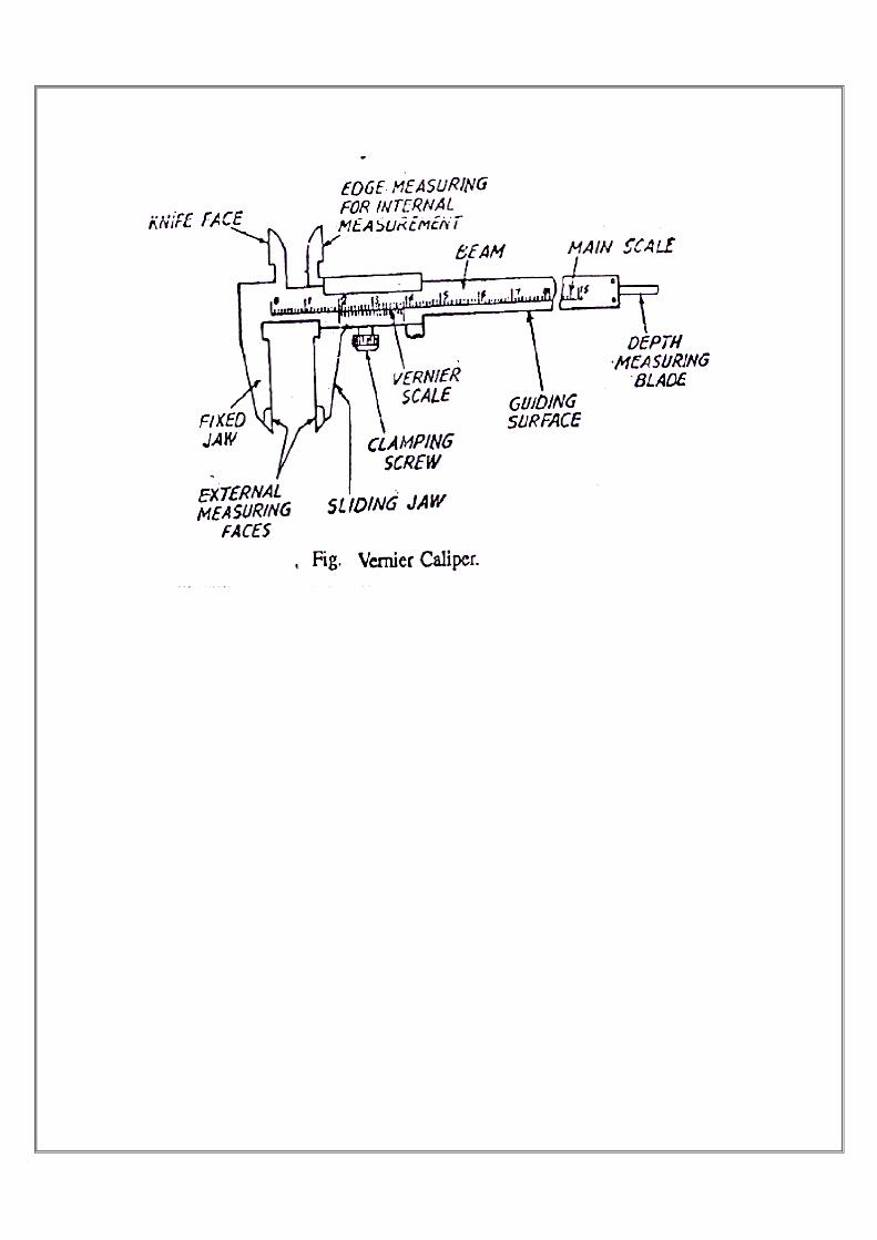
Pierre Vernier, a Frenchman, devised principle of Vernier for precise measurements in 1631. The Vernier Caliper consists of two scale one is fixed mad the other is movable. The movable scale, called Vernier Scale. The fixed scale is calibrated on L-shape frame and caries a fixed jaw. The Vernier scale slides over the main scale and carries over the movable jaw. Also an arrangement is provided to lock the sliding scale on fixed main scale.
Principle of Vernier Caliper:
The principle of Vernier is based on the difference between two scales or divisions, which are nearly, but not quite alike for obtaining small difference. It enables to enhance the accuracy of measurement.
Least Count: Least count is the minimum distance which can be measured accurately by the Instrument. Least Count of Vernier Caliper is the difference between the value of main scale division and Vernier Scale Division. Thus Least Count = (Value of Smallest Division on Main Scale)- (Value of Smallest Division on Vernier Scale) = 1-49/50 = 0.02 mm. (or) Least Count = (Value of Minimum Division on the Main Scale)/ (Number of Division on Vernier Scale ) = 1/50 = 0.02 mm.

4
4. PROCEDURE:
The given component is fixed between the jaws firmly, i.e.. in between fixed jaw and movable jaw.
The reading is to be noted down.
Procedure for taking the Reading:
1. After closing the jaws on the work surface, take the readings from the main as well as Vernier Scale. To obtain the reading , the number of divisions on the main scale is first read off. ‘Ihe Vernier Scale is then examined to determined which of its division coincide or most coincident with a division on the main scale.
2. Before using the instrument should be checked by zero error. The zero line on Vernier Scale should coincide with zero on the main scale.
3. Then take the reading in mm on main scale to the left of zero on sliding scale.
4. Now Count the no. of divisions on Vernier Scale from zero to a line which exactly Coincides with any line on the main scale.
Thus total reading = [ Main scale reading ] + [No. of divisions with a division on Main Scale ] X Least Count.
( OR ) TR = MSR + VC X LC
5. Take the reading for 4 times.
Sample Reading :
TABULAR FORM :
SLNO. MSR VC TR

5
The length / dia / height = Average of the readings = ( Trial 1+2+3+4+5) / 5 = ------------------ mm RESULT: Length / Diameter / Height = ----------------------- mm
6
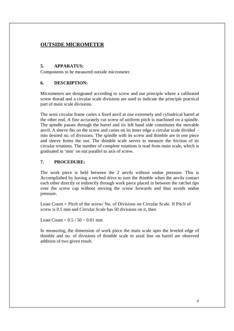
OUTSIDE MlCROMETER
5. APPARATUS:
Components to be measured outside micrometer.
6. DESCRIPTION:
Micrometers are designated according to screw and nut principle where a calibrated screw thread and a circular scale divisions are used to indicate the principle practical part of main scale divisions.
The semi circular frame caries a fixed anvil at one extremely and cylindrical barrel at the other end. A fine accurately cut screw of uniform pitch is machined on a spindle. The spindle passes through the barrel and its left hand side constitutes the movable anvil. A sleeve fits on the screw and caries on its inner edge a circular scale divided -into desired no. of divisions. The spindle with its screw and thimble are in one piece and sleeve forms the nut. The thimble scale serves to measure the friction of its circular rotations. The number of complete rotations is read from main scale, which is graduated in ‘mm’ on nut parallel to axis of screw.
7. PROCEDURE:
The work piece is held between the 2 anvils without undue pressure. This is Accomplished by having a retched drive to turn the thimble when the anvils contact each other directly or indirectly through work piece placed in between the ratchet tips over the screw cap without moving the screw forwards and thus avoids undue pressure.
Least Count = Pitch of the screw/ No. of Divisions on Circular Scale. If Pitch of screw is 0.5 mm and Circular Scale has 50 divisions on it, then
Least Count = 0.5 / 50 ~ 0.01 mm
In measuring, the dimension of work piece the main scale upto the leveled edge of thimble and no. of divisions of thimble scale to axial line on barrel are observed addition of two given result.

7

8
8. OBSERVATIONS : Measuring the below given component with 0-25 , 0.01 mm Micrometer.
SAMPLE CALCULATIONS :
TR = SR + (CSR X LC )
TR = TOTAL READING ; SR = SLEVE READING ; CSR = CIRCULAR SCALE
READING ; LC = LEAST COUNT
TABLE FORMAT :
SLNO. MSR VC TR
------------------------------------------------------------------------- The average diameter of the component is ------------------------------------------------------------------------- ......... mm.
9. PRECAUTIONS :
The thimble should be turned with ratchet only and to have standard condition and to prevent excess deformation of work piece.
10. RESULT:
The required outer diameter of the given components using outside micrometer is obtained.

9
REVIEW QUESTIONS .
1. What are Vernier Calipers?
2. What is Micrometer ?
3. What is the Least Count of Vernier & Outside Micrometer ?
4. What are applications of Vernier & Outside Micrometer ?
5. What are the errors in Vernier & Outside Micrometer ?
6. Compare Vernier & Outside Micrometer .

10
EXPERIMENT-2
1. AIM :
To measure bores of a given specimen by using Inside Micrometer and Dial Bore Indicator.
2. APPARATUS AND ACCESORIES REQUIRED :
a ) Inside micrometer b ) Dial bore indicator c ) Dial indicator d ) Specimen
3. SPECIFICATION :
a) Inside micrometer : Range 5-30 mm, Least count = 0.01 mm. b) Dial bore indicator : Range 18-34 mm, Least count = 0.01 mm. c) Dial Indicator : Range 0-10 mm, Least count = 0.01 mm.
4. THEORY AND DESCRIPTION :
A) INSIDE MICROMETER :
This micrometer caliper has ‘U’ shape frame and spindle. The measuring tips are constituted by the jaws with contact surfaces which are hardened and ground to a radius. One of the Jaws is held stationary at the end and second one moves by the movement of thimble. A lock nut is provided to arrest the moment of movable right jaw.
5. PRINCIPLE : Inside
micrometer work on screw and nut principle.
6. PROCEDURE :
1. Keep the inside micrometer Jaws in the work piece.
2. When two anvils touches the sides of bore , apply pressure with ratchet. 3. See the reading & note down.
11
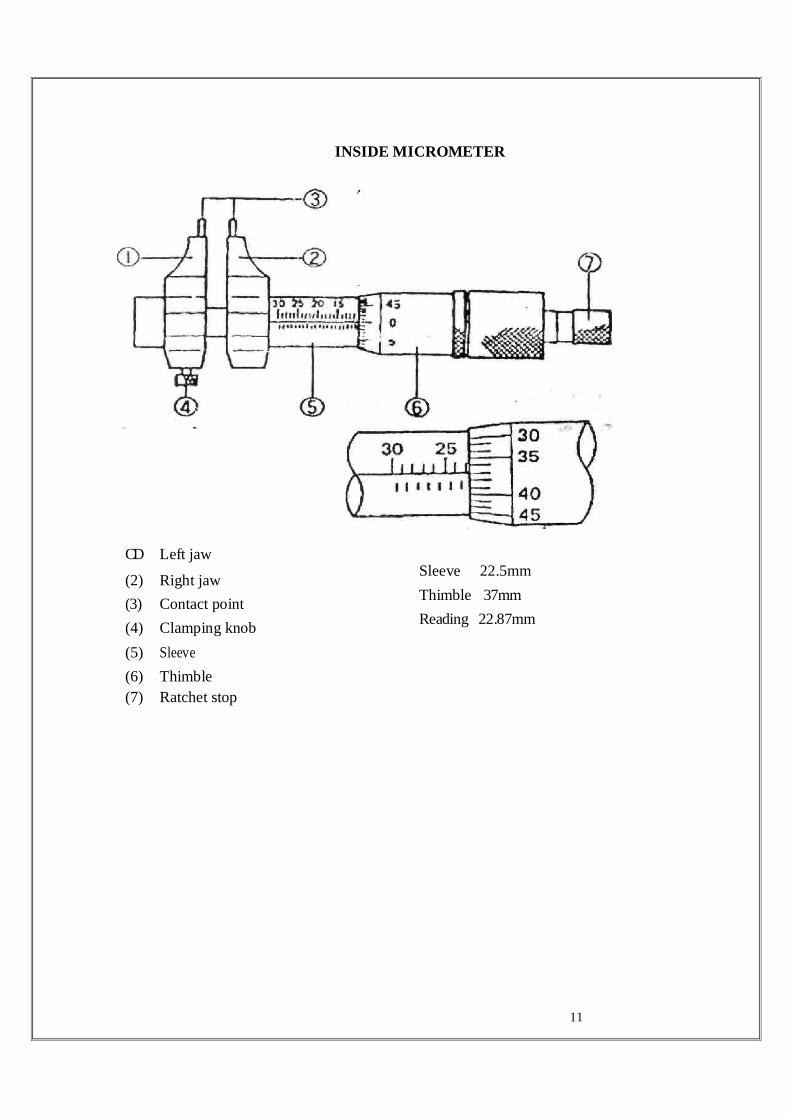
INSIDE MICROMETER
CD Left jaw
(2) Right jaw
(3) Contact point
(4) Clamping knob
(5) Sleeve
(6) Thimble
(7) Ratchet stop
Sleeve 22.5mm
Thimble 37mm
Reading 22.87mm
12
7. TABULAR FORM :
SLNO. MSR VC TR
LC = LEAST COUNT SR = SLEEVE READING CR = CIRCULAR SCALE READING TR = TOTAL READING = SR + CSR X L.C
8. IDEAL CONDITION/BEHAVIOUR :
a) When the fixed anvil and movable spindle are near during operation apply final pressure with ratchet in that position sleeve reading is zero and circular scale zero coincides with center.
b) The dial bore gauge reading checked the standard bore it give the same reading.
B) DIAL BORE INDICATIOR
THEORY AND DESCRIPTION:
Dial bore indicator consists of measuring head and guide is attached with extension rod & collars for specific dimension chosen from the table in the instrument box, holder is assembled to the measuring head and dial indicator is fixed inside the holder during tightening. The condition is initially 1 kgf is applied to the dial indicator for getting exact reading.
PRINCIPLE : Dial bore indicator is works on comparator principle.
PROCEDURE :
1) Once approximate bore is finding out by using inside micrometer.
2) Chose the same little more size extension rod & collar if necessary select and fit. 3) Keep the dial bore indicator into the specimen bore.

13

14
TABULAR FORM :
Sl.No.
Length of extension
rod + Spacing collar
Dial gauge reading Total reading
------------------------------------------------- Average bore on right side is mm. PRECAUTIONS :
a) Thimble should be turned with ratchet only and to have standard condition and to prevent excess deformation of work piece.
b) Only after checking the reading with inside micrometer, then use the dial bore gauge. c) The specimen measured surface should be smooth. d) See the reading without parallax error. e) Initially set the brezel of dial gauge to zero.
VIVA QUESTIONS :
1) What are the precautions required during use of inside micrometer & dial Bore indicator ?
2) Which one is more precise when compared to inside micrometer & dial bore Indicator ?
3) What are the applications of inside micrometer & dial bore indicator ? 4) How do you find the least count of inside micrometer ? 5) What are the other instruments for measuring bores ?
INFERENCE : The size of bore is minimum 18 mm & maximum 30 mm.
TROUBLE SHOTING :
a) Calibration is done by using standards
b) Error adjust
c) Recheck after error adjustment
APPLICATIONS :
a) Internal diameter of engineering components, slot width and length.

15
EXPERIMENT- 3
MEASUREMENT OF GEAR TOOTH THICKNESS
1. AIM:
To measure spur gear tooth thickness by using Gear tooth vernier.
2 INSTRUMENTS AND MATERIAL REQUIRED :
a) Gear tooth vernier caliper
b) Spur gear
3 SPECIFICATIONS:
a) Gear Tooth vernier calipers – range 0-150 mm , LC = 0.02mm
b) Spur gear size = Standard size
c) Vernier calipers - range 0-150 mm, LC = 0.02mm
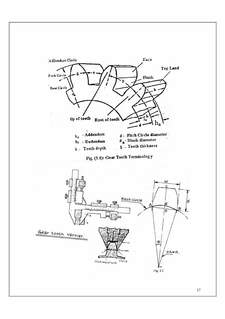
4. TERMINLOGY OF GEAR TOOTH : Fig (3.1)
Pitch circle diameter (P.C.D): It is the diameter of a circle which by pure rolling action would produce the same motion as the toothed gear wheel.
Module (m) : It is defined as the length of the pitch circle diameter per tooth. Thus if P.C.D of gear be ‘D’ and number of teeth ‘N’, then module (m) = D/N. it is generally expressed in mm.
Diametric pitch : It is expressed as the number of teeth per inch of the P.C.D.
Circular pitch : It is the arc distance measured around the pitch circle from the flank of one tooth to a similar flank in the next tooth. C.P = ПD/N = Пm
Addendum : This is the radial distance from the pitch circle to the tip of the tooth. Its value is equal to one module.
Clearance : This is the radial distance from the tip of a tooth to the bottom of a mating tooth space when the teeth are symmetrically engaged. Its standard value is 0.157 m
Dedendum : This is the radial distance from the pitch circle to the bottom of the tooth space.
16
Dedendum = Addendum + clearance = m + 0.157 m = 1.157 m.
Blank diameter : This is the diameter of the blank from which gear is cut. It is equal to P.C.D plus twice the addendum.
Blank diameter = P.C.D + 2m = mN + 2m = m (N+2)
Tooth thickness : This is the arc distance measured along the pitch circle from its intercept with on flank to its-intercept with the other flank of the same tooth.
Normally tooth thickness = 1/2 (C.P) = 1/2 (ΠM)
But thickness is usually reduced by certain amount to allow for some amount of backlash and also owing to addendum correction.
Face of tooth : It is that part of the tooth surface which is above the pitch surface.
Flank of tooth: It is that part of the tooth surface which is lying below the pitch surface.
5. PRINCIPLE :
MEASUREMENT OF TOOTH THICKNESS :
The permissible error or the tolerance on thickness of tooth is the variation of actual thickness of tooth from its theoretical value. The tooth thickness is generally measured at pitch circle and is therefore, the pitch line thickness of tooth i.e., length of an arc, which is difficult to measure directly. In most of the cases, it is sufficient to measure the chordal thickness i.e, the chord joining the intersection of the tooth profile with the pitch circle. Also the difference between chordal tooth thickness and circular tooth thickness is very small for gear of small pitch. The thickness measurement is the most important measurement because most of the gears manufactured may not undergo checking of all other parameters, but thickness measurement is a must for all gears.
The tooth thickness can be very conveniently measured by a gear tooth vernier. Since the gear tooth thickness varies from the tip to the base circle of the tooth, the instrument must be capable of measuring the tooth thickness at a specified position on the tooth. Further this is possible only when there is some arrangement to fix that position where the measurement is to be taken. The gear tooth vernier has two vernier scales and they are set for the width (w) of the tooth and the depth (d) from the top, at which ‘w’ occurs.
17

18
Considering one gear tooth, the theoretical values of ‘w’ and ‘d’ can be found which may be verified by the instrument. From fig .3.2) Chordal thickness = w = AB = 2AD <AOD = θ = 360°/4N, where ‘N’ is the number of teeth. W = 2AD = 2 x AO. Sin θ = 2R. Sin 360°/4N ( R = Pitch circle radius)
Module (m) = P.C.D/Number of teeth = 2R/ N ∴R = 2
.mN
Chordal thickness (w) = 2. N
SinmNN
SinmN 00 90
..4
360
2
.=
Also from fig (3.2) d = OC – OD. But OC = OE + Addendum = R+m = [N.m/2]+m and But OD = R Cos θ = N.m/2 Cos900/N. ∴
N
Nmm
mN 090cos
22
.−+
∴ Chordal addendum (d) =
−+
NCos
N
mN 09021
2
.
6. PROCEDURE: i) Count the number of teeth (N) on the gear, ii) Measure the outside diameter (Do) of the gear.
iii) Calculate the module from the relation, m = )2(
0
+N
D
iv) Calculate the value of chordal addendum (d) from equation (3.1) v) Set the gear tooth vernier caliper for depth ‘d’ and measure ‘w’ i.e., chordal thickness of tooth. vi) Repeat the measurement on other teeth and determine an average value. 7. OBSERVATIONS:
a) Number of teeth on gear, N = -------
b) Outside diameter of gear (Do) = -----------
S.No. Chordal tooth thickness, w mm
1.
2.
3.
4.
5.

19
8. CALCULATIONS:
i) Chordal addendum (d) = −−−−−−=
−+
NCos
N
mN 09021
2
.
ii) Chordal thickness (w) = N.m Sin −−−−−=
N
090
9. IDEAL CONDITIONS / BEHAVIOUR : The instrument should be error free, Repeatability is required. 10. PRECAUTIONS: i) Don’t press the jaws to tight. ii) See the reading without parallax error. 11. RESULTS:
The theoretical value of gear tooth thickness may differ from the measured value due to the manufacturing inaccuracies.
12. VIVA QUESTIONS: i. Define various elements of a gear?
ii) What is Chordal addendum? iii) What is chordal thickness of gear tooth iv) What are the various parts of gear tooth Vernier? v) Differentiate gear tooth Vernier from ordinary Vernier? vi) What are the different types of gears? vii) What are the various tests conducted on gears? viii) What is the other parameter to be measured in gear by using other testing equipment? ix) What is rolling gear test? x) What are the various quantitative test on gears?
13. INFERENCES:
14. TROUBLE SHOOTING: i) Any worn out parts are there replace with new one. ii) Calibrate the instrument with standard slip gauges. 15. APPLICATIONS: It is used for measuring gear tooth thickness & depth 12. REVIEW QUESTIONS :
i) Define various elements of a gear.
ii) What is Chordal addendum ?
iii) What is Chordal thickness of gear tooth ?
iv) What are various parts of gear tooth vernier ?

20

21
EXPERIMENT-4
ANGULAR MEASUREMENT BY BEVEL PROTRACTOR AND SINE BAR
1. AIM:
a) To measure the angle between two faces of a given component using Bevel protractor. b) To measure the taper angle of a given component using sine bar.
2. EQUIPMENT AND ACCESSORIES REQUIRED :
i) Bevel protractor with vernier and acute angle attachment (150/300 mm blades), ii) Sine bar (100 mm size) iii) Surface plate iv) Slip gauges v) Dial gauge (0.01 mm least count), vi) Slotted angle plate, vii) Bolts for locking sine bar to angle plate ix) clamps for locking component to sine bar.
3 THEORY AND DESCRIPTION :
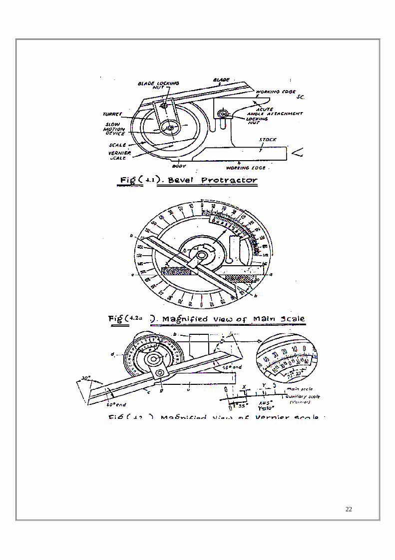
3.1 Bevel Protractor:
It is the simplest instrument for measuring angle between two faces of component. It consists of a base plate attached to the main body and an adjustable blade which is attached to a circular plate called turret containing vernier scale. The adjustable blade is capable of rotating freely about the centre of the main scale ( graduated around a complete circle from 0° to 90°, 90° to 0° and 0° to 900, 90° to 0° ) engraved on the body of the instrument and can be locked in any position. An acute angle attachment is provided at the top as shown in fig (4.1) to measure acute angles. The base of the base plate is made flat so that it could be laid flat upon the work and any type of angle measured. It is capable of measuring from 0° to 360°.
The vernier scale has 24 divisions coinciding with 46 main scale divisions (23 on either side ) as shown in fig (4.2) The vernier scale is graduated to the right and left of zero upto 60 minutes, each of the 12 graduations representing 5 minutes. Since both the protractor dial and vernier scale have graduations in both directions from zero, any angle can be measured, but it should be remembered that the vernier must be read in the same direction from zero as the protractor either left or right. If the zero graduation on the vernier scale coincides with a graduation on the protractor dial, the reading is in exact degrees, but if some other graduation on the vernier scale coincides with a protractor graduation, the number of vernier graduations multiplied by 5 minutes, must be added to the number of degrees read between the zeros on the protractor dial and vernier scale. Magnified view of main scale is shown in fig (4.2a)
22

23
3.2 Sine Principle and Sine bar :
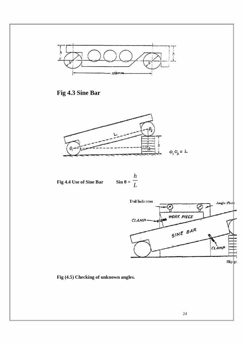
The Sine principle uses the ratio of the length of two sides of a right angle triangle in deriving a given angle. The measurement is usually limited to 45° from loss of accuracy point of view. The accuracy with which the sine principle can be put to use is dependent in practice, on some form of linear measurement. The sine bar in itself is not a complete measuring instrument. Another datum such as a surface plate is needed, as well as other auxiliary equipment, notably slip gauges, and indicating device to make measurements. Sine bars used in conjunction with slip gauges constitute a very good device for the precise measurement of angles. Sine bars are used either to measure angles very accurately or for locating any work to a given angle within very close limits. Sine bars are made from high carbon, high chromium, corrosion resistant steel, hardened, ground and stabilized. Two cylinders of equal diameter are attached at the ends. The axes of these two cylinders are mutually parallel to each other and also parallel to and at equal distance from the upper surface of the sine bar. The distance between the axes of the two cylinders is exactly 5 inches or 10 inches in British System and 100, 200 and 300 mm in metric system. The Various parts are hardened and stabilized before grinding and lapping. All the working surfaces and the cylindrical surfaces of the rollers are finished to surface finish of 0.2 μ Ra value or better. Depending upon the accuracy of the centre distance, sine bars are graded as of A grade or B grade. B grade of sine bars are guaranteed accurate upto 0.02 mm/m of length and A grade sine bars are more accurate and guaranteed upto 0.01 mm/m of length. There are several forms of sine bars, but the one shown in fig (4.3) is most commonly used. Some holes are drilled in the body of the bar to reduce the weight and to facilitate handling.
The accuracy of sine bar depends on its constructional features : i) The two rollers must have equal diameter and be true cylinders ii) The rollers must be set parallel to each other and to the upper face, iii) The precise centre distance between the rollers must be known iv) The upper face must have a high degree of flatness. 3.2.1 Use of Sine bar:
a) Measuring known angles or locating any work to a given angle : For this purpose the surface plate is assumed to be having a perfectly flat surface, so that its surface could be treated as horizontal. One of the cylinders or rollers of sine bar is placed on the surface plate and other roller is placed on the slip gauges of height ‘h’ as shown in fig (4.4) . Let the sine bar be set at angle θ . Then Sin θ = h/L
Where, L = Distance between the centre of rollers. Thus knowing θ, h can be found out and any work could be set at this angle as the top face of sine bar is inclined at angle θ to the surface plate. The use of angle plates and clamps could also be made in case of heavy components. For better results, both the rollers could also be placed on slip gauges of height h1 and h2 respectively. Then Sin θ = (h2-h1)/L
24
Fig 4.3 Sine Bar
Fig 4.4 Use of Sine Bar Sin θ = L
h
Fig (4.5) Checking of unknown angles.

25
b) Checking of unknown angles :
Many a times, angle of a component to be checked is unknown. In such a case, it is necessary to first find the angle approximately with the help of a bevel protractor. Let the angle be θ . Then the sine bar is set at an angle θ and clamped to an angle plate. Next, the work is placed on sine bar and clamped to angle plate as shown in fig (4.5) and dial indicator is set at one end of the work and moved to the other, and deviation is noted. Again slip gauges are so adjusted that dial indicator reads zero across work surface.
If deviation noted down by the dial indicator is δh over a length of L of work, then height of slip gauges by which it should be adjusted is equal to δ h x L/L1.
4 PROCEDURE :
4.4.1 Angle measurement by Bevel protractor :
i) The base plate of the Bevel protractor is placed on the top horizontal surface of the component, ii) Blade locking nut is loosened and by rotating the blade about the centre of the main scale, the working edge of the blade is made to coincide with the inclined surface of the component, iii) Blade is locked in that position by tightening the nut. iv) Vernier scale division coinciding with main scale division is noted.
Inclination of the surface with respect to horizontal is calculated as follows : Angular reading = (Vernier scale division x 5minutes) + Main scale division in degrees.
4.4.2 Angular measurement by sine bar :
i) The sine bar is made to rest on surface plate with rollers contacting the datum (surface plate) ii) Place the component on sine bar and lock it in position. iii) Lift one end (roller) of the ‘sine bar and place a pack of slip gauges, underneath the roller. The height of the slip gauges (h) should be selected such that the top surface of component is parallel to the datum plate (surface plate). The parallelism can be assessed by making the stylus of a dial indicator mounted on a dial gauge stand in contact with the upper surface of component and sliding the stylus along the component surface. If both the surfaces are perfectly parallel, the pointer on the dial gauge shows the same reading throughout the travel of the dial gauge stylus. If the surfaces are not parallel, then the height of the slip gauge pack (h) can be altered and procedure for checking parallelism can be repeated.)
Record the final height of slip gauge pack used for achieving parallelism
Calculate inclination θ = Sin-1 (h/L)

26
5 PRECAUTIONS :
i) The sine bar should not be used for angle greater than 60° because any possible error in construction is accentuated at this limit.
ii) Accuracy of sine bar should be ensured.
iii) As far as possible longer sine bar should be used since many errors are reduced by using longer sine bars.
27
EXPERIMENT - 5
FLATNESS TEST
1. AIM: To find the flatness of a given surface plate.
2. API’ARATUS: Surface plate and precision spirit level.
3. THEORY AND DESCR’.PTION:
The simplest form of flatness testing is possible by comparing the surface with an accurate surface.
Spirit level is used in special cases and called Clinometers, precision micro-optic clinometers utilizes bubble unit with a prismatic coincidence reader which presents both ends of the bubble an adjacent images in a spirit field.
Leveling helps in the coincidence of the 2 images, making it very easy to sec when the bubble is exactly centered without reference to any graduations. The special features to precision micro-optic clinometers arc direct reading over range 0-360°, optically reading system, main coarse setting, slow motion screw to fine setting. The least count of precision spirit level is 0.01 mm.
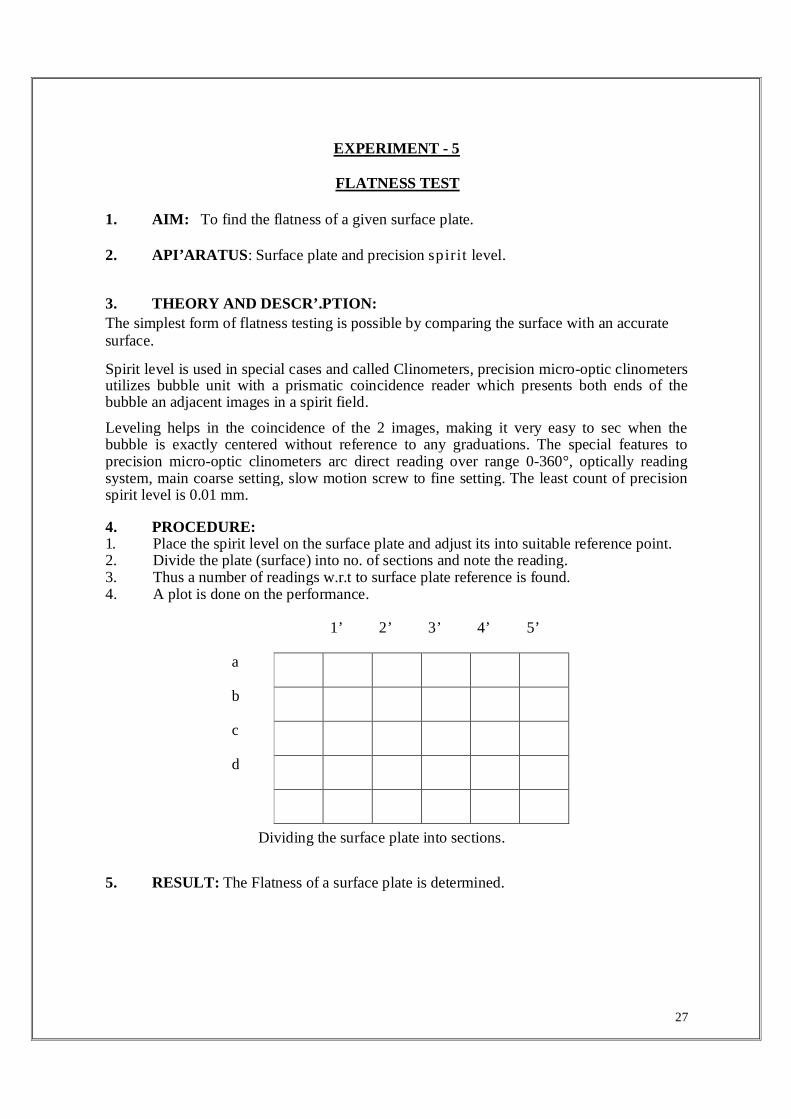
4. PROCEDURE: 1. Place the spirit level on the surface plate and adjust its into suitable reference point. 2. Divide the plate (surface) into no. of sections and note the reading. 3. Thus a number of readings w.r.t to surface plate reference is found. 4. A plot is done on the performance.
1’ 2’ 3’ 4’ 5’
a
b
c
d
Dividing the surface plate into sections.
5. RESULT: The Flatness of a surface plate is determined.
28
EXPERIMENT-6
SURFACE ROUGHNESS MEASUREMENT 1. AIM:
i) To measure the surface roughness of the given specimens using surface roughness tester.
ii) To show the variation of surface roughness as a function of cutting conditions i.e., speed, feed, depth of cut and tool geometry etc.,
2. MEASURING INSTRUMENTS AND MATERIAL REQUIRED : a) Surface roughness tester ( SJ - 201) b) Precision roughness specimen, Test specimens, Calibration stage c) Height gauge, Adapter for the height gauge, support feet d) Nose pieces, Digimatic data processor ( DP- 1 HS)
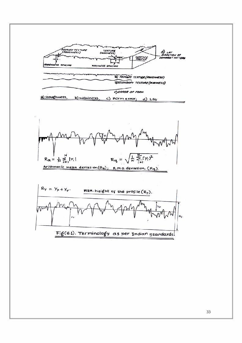
3 TERMINOLOGY AS PER INDIAN STANDARDS : Fig (6.1)
Surface roughness : It concerns all those irregularities which form surface relief and which are conventionally defined within the area where deviations of form and waviness are eliminated.
Primary texture (Roughness) : It is caused due to the irregularities in the surface roughness which result from the inherent action of the production process. These are deemed to include transverse feed marks and the irregularities within them.
Secondary texture (Waviness) : It results from the factors such as machine or work deflections, vibrations, chatter, heat treatment or warping strains, waviness is the component of surface roughness upon which roughness is superimposed.
Centre line: The line about which roughness is measured.
Lay : It is the direction of the “ predominant surface pattern: ordinarily determined by the method of production used.
Traversing length : It is the length of the profile necessary for the evaluation of the surface roughness parameters. The traversing length may include one or more sampling lengths.
Sampling length (l) : Is the length of profile necessary for the evaluation of irregularities to be taken into account. This is also known as the cut - off length as regard to the measuring instruments. It is measured in a direction parallel to the general direction of profile.
4. THEORY:
Surface texture is deemed to include all those irregularities which, recurring many times across the surface, tend to form on it a pattern or texture. The irregularities in the surface texture which result from the inherent action of the production process is called roughness or primary texture. That component of surface texture upon which roughness is super imposed is called waviness or secondary texture. This may result from such factors as machine or work deflections, vibrations, chatter, heat treatment or warping strains. The direction of the predominant surface pattern, ordinarily determined by the production method used is called lay. The parameters of the surface are conveniently defined with respect to a straight reference line. The most widely used parameter is the arithmetic average departure of the filtered profile from the mean line. This is known as the CLA (Centre - Line - Average) or Ra (roughness average)
29
Arithmetic mean deviation of the Profile, Ra: Ra is the arithmetic mean of the absolute values of the profile deviations (Yi) from the mean line.
Ra = ∑=
N
iiy
N 1
1
Root-mean-square deviation of the Profile, Rq : Rq is the square root of the arithmetic mean of the squares of profile deviations (Yi) from the mean line.
Ra = ∑=
N
iiy
N 1
21
Maximum height of the Profile, Ry : Ry is the sum of height Yp of the highest peak from the mean line and depth Yv of the deepest valley from the mean line. Ry = Yp + Yv
5. OUTLINE OF SURF TEST SJ-201 :
The surftest - 201 is a shop-floor type surface roughness measuring instrument, which traces the surfaces of various machines parts, calculates their surface roughness based on roughness standards, and displays the results.
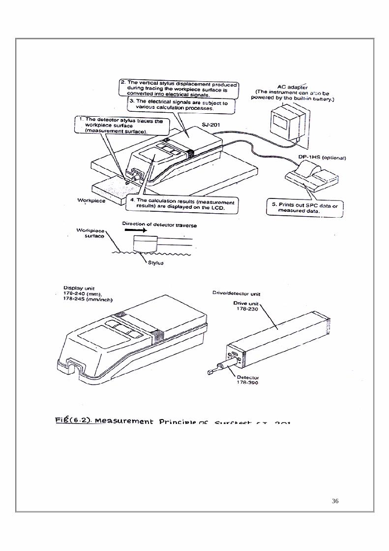
5.1. Surf Test SJ-201 Surface roughness measurement principle :
A pick-up which is usually called as the ‘‘Stylus” attached to the detector unit of the surf test SJ-201 will trace the minute irregularities of the work piece surface. The vertical stylus displacement during the trace is processed and digitally displayed on the liquid crystal display of the surf test SJ-201. The measurement principle of surf test SJ-201 is shown in fig (6.2). The instrument consists of the display unit and drive/detector unit. The drive/detector unit is designed to be removable from the display unit. Depending on the shape of the work-piece, it may be easier to perform measurement without mounting the drive/detector unit to the display unit. Name of each part on the display unit is shown in fig (6.3). The detector inturn can be detached from the drive unit. Each time a measurement task has been completed with the surf test SJ-201, it is recommended that the detector be detached from the drive unit and stored in a safe place.
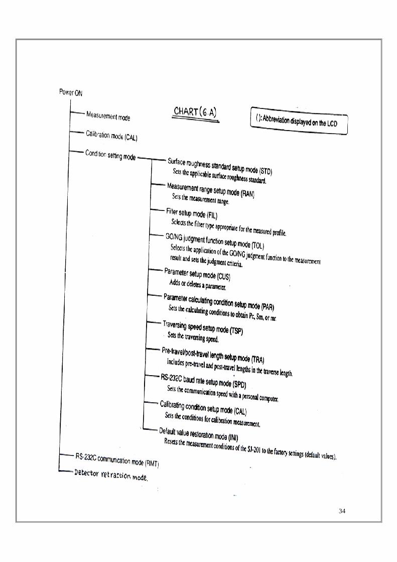
5.2. List of Surf Test SJ-201 Operation mode :
The surf test SJ-201 has various operation modes including the measurement mode, calibration mode, condition setting mode, RS-232 C communication mode, and detector retraction mode. Measurement mode : Starts and stops measurement, calculates and selects measurements parameters to be displayed, and performs SPC output. Calibration mode:
30
Sets the calibration value prior to measurement and performs calibration measurement. Condition Setting mode: Sets and modifies measurement conditions. This mode has 11 sub-modes as shown in chart (6.A). RS-232C Communication mode: Used for communication with a personal computer. Detector retraction mode: Retracts the detector as required. Relationship between the operation modes and available keys is shown in Table (6.B)
6 MEASUREMENT OF SURFACE ROUGHNESS :
Surface roughness measurement with the surf test SJ-201 includes
i) Mounting/dismounting the drive unit/detector, and cable connection, etc. according to he feature of the work piece to be measured, ii) Selection of power supply i.e., either the AC adapter or built-in battery, iii) Modifying the measurement conditions as necessary, iv) Calibrating surf test SJ-201 to adjust the detector gain for correct measurements, v) Measuring the roughness specimen and display the result, vi) outputting the measurement data or perform communication with a personal computer via the RS-232C interface.
7. PROCEDURE :
8. Modifying measurement conditions :
Table (6.C) shows the measurement conditions that can be modified by the user. If they are not modified, then measurement will be performed according to the default values, measurement conditions are modified according to the surface roughness parameters, the amplitude of roughness, the conditions of the objective area of measurement, etc.
Table – (6.A)
Table – (6.B)
Table – (6.C)
The surf test SJ-201 can obtain each roughness parameter based on the new JIS, old JIS, DIN ISO and ANSI standards. Evaluation according to any one of the standards may be obtained from Reference information (User’s manual)
8.1. Calibration of measuring instrument:
The process of calibration involves the measurement of a reference work piece (precision roughness specimen) and the adjustment of the difference ( gain adjustment), if there is any between the measured value and the reference value (precision roughness specimen). With out properly calibrating the instrument, correct measurements cannot be obtained. Calibration of surf test SJ-201 with the supplied precision roughness specimen must be performed with the default values mentioned in Table (6.D).
31
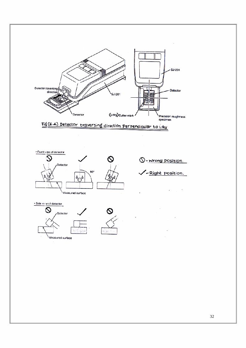
i) Precision roughness specimen and calibration stage are placed on a level table.
ii) Surf Test SJ-201 is mounted on the calibration stage.
iii) Surf Test SJ-201 is set so that the detector traversing direction is perpendicular to the cutter mark of the precision roughness specimen. It should be confirmed that the detector is parallel to the measured .surface as shown in fig (6.3).
iv) If [CAL/STD/RANGE] key is pressed in the measurement mode, the calibration mode is entered and current calibration value is displayed. In this state the calibration value can be modified, if the displayed value is different from that marked on the precision roughness specimen. .
v) [n/Ent] key is pressed after confirming the displayed value, so that the entered calibration value is set.
vi) [START/STOP] key is pressed to begin the calibration measurement. The symbol “--”is displayed while the detector is traversing and the measured value will be displayed when the measurement has been completed.
vii) [n/Ent] key is pressed so that the calibration factor is updated, completing the entire calibration operation.
viii) [MODE/ESC] key is pressed. This restores the measurement mode and retains the calibration factor obtained in the previous operation.
8.2. Actual measurement of roughness specimen :
Surf Test SJ-201 is placed on the work piece, if the work piece surface is large enough. For measurement to be successful, it should be performed on a firm base that is insulated as well as possible from all sources of vibration. If measurement is performed being subject to significant vibrations, results may be un reliable.
i) Work piece is positioned so that the measured surface is level. ii) Surf Test SJ-201 is placed on the work piece, In this operation SJ-201 is supported by two reference surfaces at the bottom of driving unit. It must be confirmed that the stylus is in proper contact with the measured surface and the detector is parallel to the measured surface.
32
33
34

35
Relation ship between the operation modes and available keys.
TABLE (6.B)
Operation mode Symbol (on LCD)
Key for mode switching
Calibration mode CAL [CAL/STD/RANGE]
Surface roughness standard setup
STD [CAL/STD/RANGE]
Measurement range setup mode
RAN [CAL/STD/RANGE]
Filter setup mode FIL [FILTER/TOL/CUST]
GO/NG judgment function setup mode
TOL [FILTER/TOL/CUST]
Parameter calculating condition setup mode
PAR [FILTER/TOL/CUST]
Traversing speed setup mode TSP [MODE/ECE]
Pre-travel/post travel length setup mode
TRA [MODE/ECE]
RS-232 C baud rate setup mode
SPD [MODE/ECE]
Calibrating condition setup mode
CAL [MODE/ECE]
Default value restoration mode
INI
Press [POWER/DATA] while simultaneously holding down [PARAMETER] and [STAR/STOP] during auto sleep.
Rs-232 C communication mode
RMT Press [POWER/DATA] While holding down [REMOTE] during auto sleep
Detector retraction mode OFF
ON
Retraction: Press [POWER/DATA] while holding down[START/STOP] during auto sleep. Cancelling retraction:
Press [STAR/STOP] if the detector is retracted and the power is on.
36

37

38

39
iii) [START/STOP] key is pressed in the measurement mode, the detector starts traversing to perform measurement, iv) After the measurement has been completed, the measured value is displayed on the LCD. v) [PARAMETER] key is pressed until the desired parameter value is displayed on the LCD.
8.3. Outputting measurement result:
i) The Surf Test SJ-201 is connected to a Digimatic data processor (DP - IHS) to output the measurement results ( including the unit of measurement ) as SPC data,
ii) DP-IHS is turned to ‘ON’ position, iii) [PARAMETER] key is pressed until the objective parameter for output is
displayed, iv) [POWER/DATAJ key is pressed so that the measurement result will be outputted from the Surf Test SJ-201 to the DP-1HS.
9. PRECAUTIONS :
i) Never touch the stylus, otherwise it may be damaged. ii) Do not hold the detector when detaching the drive/detector unit. Otherwise, the detector may be damaged,
iv) Confirm that the detector is parallel to the measured surface, v) Confirm that the stylus is in proper contact with the measured surface, vi) Calibration of SJ - 201 with the precision roughness specimen must be
performed with the default values that have been used for calibrating the roughness specimen.
10. REVIEW QUESTIONS :
i) What is primary texture ?
ii) What is secondary texture ?
iii) What is Lay?
iv) What do you mean by traversing length and sampling length ?
v) Define Ra, Rq and Ry
vi) What is calibration ? and why is it necessary for roughness measurement ?
vii) How will you output the SPC data from surf test SJ-201 to DP-IHS printer ?
viii) What is the measurement principle of surf test SJ-201 ?
ix) What are the various operation modes in surf test SJ-201 ?
x) How will you modify the measurement conditions ?

40
EXPERIMENT - 7
ALIGNMENT TEST OF LATHE
1. AIM :
To perform various alignment tests on Lathe.
2. INSTRUMENTS REQUIRED:
i) Dial gauges ii) Test mandrels iii) Straight edges and squares iv) Spirit levels etc. v) Angle brackets
3. MACHINE TOOL TESTS :
In most cases the production or machining of a given geometric surface is achieved through combination of work-tool movements. In other words, the machined surface is generated, and the accuracy of the surface depends on the accuracy of the mating elements present in the machine tool.
The various tests applied to any machine tool could be grouped as below.
a) Tests for the level of installation of machine in horizontal and vertical planes.
b) Tests for flatness of machine bed and for straightness and parallelism of bed ways or bearing surfaces.
c) Tests for perpendicularity of guide ways to other guide ways or bearing surfaces.
d) Tests for the true running of the main spindle and its axial movements.
e) Tests for parallelism of spindle axis to guide ways or bearing surfaces.
f) Tests for the line of movement of various members, i.e. saddle and table cross-slides etc. along their ways.
4. ALIGNMENT TESTS ON LATHE :
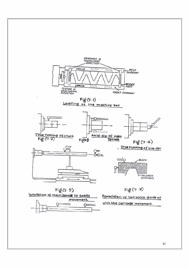
4.1 Leveling of the machine : The level of the machine bed in longitudinal and transverse directions is tested by a sensitive spirit level. The saddle is kept approximately in the centre of the bed support feet. The spirit level is then placed at a-a (Fig 7.1), to ensure the level in the longitudinal direction. It is then traversed along the length of bed and readings at various places noted down.
For tests in transverse direction the level is placed on a bridge piece to span the front and rear guide ways and their reading is noted. It is preferable to take two readings in longitudinal and transverse directions simultaneously so that the effect of adjustments in one direction may also be observed on the other. The readings in transverse direction can reveal any twist in the bed. It may be noted hat the two guide ways may be perfectly leveled in longitudinal direction, but might not be parallel to each other. This is revealed by the test in transverse direction.
41

42
4.2 : True Running of Locating Cylinder of Main Spindle:
Locating cylinder is provided to locate the chuck or face plate and the true running of which depends on true running of the locating cylinder. The dial indicator is fixed to the carriage (or any other fixed member) and the feeler of the indicator touches the locating surface as shown in fig (7.2). The surface is then rotated on its axis and indicator should not show any movement of needle. If there is any change in the indicator reading, it must be recorded and be verified with the limiting values.
4.3 Axial Slip of Main Spindle and True Running of Shoulder Face of Spindle Nose:
Axil slip is the movement of the spindle in axial direction and is due to the manufacturing error. To test this, the feeler of the dial gauge rests on the face of the locating spindle shoulder and the dial gauge holder is clamped to the bed as shown in fig (7.3). The locating cylinder is then rotated and the change in reading noted down. The readings are taken at two diametrically opposite points. The total error indicated by the movement of the pointer includes three main sources of errors.
i) Axial slip due to error in bearings supporting the locating shoulder, i.e. the bearings are not perpendicular to the axis of rotation and due to it a point on the shoulder will move axially in & out at diametrically opposite points, ii) Face of the locating shoulder not in a plane perpendicular to the axis of rotation iii) Irregularities of front face. Due to axial slip, in screw cutting, the pitch will not be uniform due to periodic movement of the spindle.
4.4: True running of Live centre:
Work piece is rotated along with the Live centre. If it is not true with the axis of movement of the spindle, eccentricity will be caused while turning a work, as the job axis would not coincide with the axis of rotation of the main spindle.
For testing this error, the feeler of the dial indicator is pressed perpendicular to the taper surface of the centre as shown in fig (7.4), and the spindle is rotated. The deviation indicated by the dial gauge gives the trueness of the centre.
4.5: Parallelism of the main spindle to Saddle movement:
If the axis of the spindle is not parallel to bed in horizontal direction, a tapered surface is produced. Any deviation from parallelism of spindle axis from bed in vertical axis will produce a hyperboloid surface. For this test, a mandrel is fitted in the taper socket of the spindle. Mandrel has a concentric taper shank which is close fit to the spindle nose taper. The feeler of the dail-indicator is pressed on the mandrel and the carriage is moved. The indication in the horizontal plane is given by dial (b) and in vertical plane by dial (a) as shown in fig (7.5).
4.6: running of taper socket in main spindle: If the tapered hole of the socket is not concentric with the main spindle axis, eccentric and tapered jobs will be produced. To test it, a mandrel is fitted into the tapered hole and readings at two extremes of the mandrel are taken by means of a dial indicator as shown in fig (7.6).
43
44
4.7: Parallelism of tail stock guide ways with the movement of carriage:
Sometimes the job is held between head stock and tail stock for turning. In that case, they axis must coincide with the tail stock centre. If the tail stock guile ways are not parallel wit the carriage movement there will be some offset of the tail stock centre results in taper turning To check the parallelism of tail stock guide ways in horizontal and vertical planes, a block placed on the guide was as shown in fig (7.7) and the feeler of the indicator is touched on tl horizontal and vertical surfaces of the block. The dial indicate:’ is held in the carriage ai carriage is moved. Any error is indicated by the pointer of dial indicator.
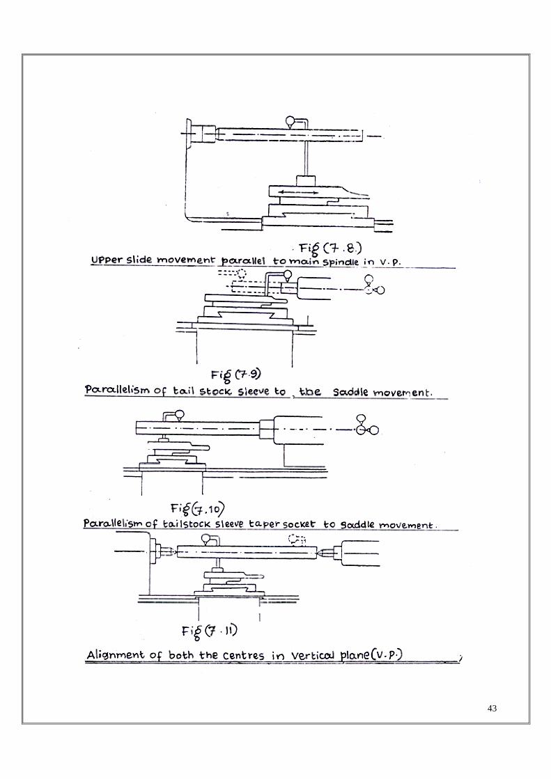
4.8 : Movement of upper slide parallel with main spindle in vertical plane: Fig (7.8)
The dial indicator is fixed in the tool post. A mandrel is fitted in the spindle. The feeler of the dial gauge is pressed against the mandrel in vertical plane and the upper slide is moving longitudinally. This error is not tested in horizontal plane because there is swiveled arrangement for taper running.
4.9 : Parallelism of tail stock sleeve to saddle movement:
If the tail stock sleeve is not parallel to the saddle movement, the height of dead centre would vary as varying lengths of sleeve are taken out. For the jobs held between two centers, it necessary that the central axis of the dead centre be coaxial with the job axis in both the plane If it is not so, the job may be ti lted up or down or in sideways due to the support of the de; centre. The test is carried out by fixing the dial indicator on the tool post and pressing tl plunger against the sleeves first in vertical and then in horizontal plane as shown in fig (7.S The carriage is moved along the full length of the sleeve and the deviations as indicated by di indicator are noted down.
4.10 : Parallelism of tail stock sleeve taper socket to saddle movement:
A mandrel is put in the sleeve socket. The dial gauge is on the tool post and plunger is press* against the mandrel and saddle is moved from fixed one side to the other. This test is came out in both the horizontal and vertical planes as shown in fig (7.10).
4.11 : Alignment of both the centers in vertical plane :
Besides testing the parallelism of the axes individually (main spindle axis and tail stock axi it is necessary to check the relative position of the axes also. Both the axes may be parallel carriage movement but they may not be coinciding. So when a job is fitted between the centre the axis of the job will not be parallel to the carriage movement. This test is to be carried out i vertical plane only. A mandrel is fitted between the two centres and dial gauge on the carriag The feeler of the dial gauge is pressed against he mandrel in vertical plane as shown in fi (7.11) and the carriage is moved and error noted down.
5. PRECAUTIONS :
i) The mandrel must be so proportioned that its overhang does not produce appreciable sag,
else the sag must be calculated and accounted for. ii) The indicator set up must be rigid, otherwise variations in readings as recorded by point may be solely due to deflection of the indicator. 6 REVIEW QUESTIONS

45
a) What is the necessity of conducting various alignment tests on lathe? b) What are the various alignment tests to be conducted on the lathe? c) What is straightness? d) What is flatness? e) What is square ness? f) What is parallelism? g) What do you mean by axial slip of main spindle? h) It is necessary to conduct alignment tests on other machine tools? If so why? Not,
why not?

46
EXPERIMENT - 8
ALIGNMENT TEST OF VERTICAL MILLING MACHINE
1 AIM :
To perform various alignment tests on vertical knee type milling machine.
2. MEASURING INSTRUMENTS REQUIRED :
i) Test mandrels ii) Straight edges and squares iii) Spirit levels iv) Slip gauges
3 ALIGNMENT TESTS ON MILLING MACHINE :
Machine tools are very sensitive to impact or shock, even heavy cast iron standards are not always solid and rigid enough to withstand stresses due to falling during transportation, and deformations may be set up. Although the machine is always carefully adjusted and aligned in the assembly department of the manufacturer, it is well known from experience that erection in the work shop of the user is not always done with sufficient care and thus inaccuracies of the work may result from the faulty erection of the machine. So the machine should be carefully leveled up by means of a spirit level before starting with the actual trial tests. Each trial measurement is based on the correct erection of the machine. No upright, base etc. can be made so rigid that it will be thoroughly free from deformation resulting from faulty erection.
Machine tools in the workshop must be able to produce work pieces of given accuracy within prescribed limits consistently and without requiring artistic skill on the part of the operator.
For acceptance test of a machine, its alignment test is performed and to see its dynamic stability, which may be poor though alignment tests are right, certain specific jobs are prepared and their accuracy checked.
The relative alignment of all parts of machine and the accuracy of the control devices and driving mechanisms are measured under no load condition. The results of these measurements must lie within the prescribed limits given by the manufacturer depending upon the grade of the machine tool.
The various tests performed on the milling machine are as described below.
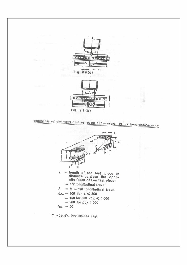
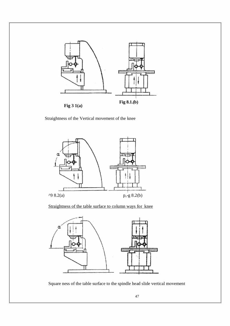
3.1 Straightness of the vertical movement of the knee :
Straightness of the vertical movement of the knee is checked in two planes
a) In the vertical plane of symmetry of the machine as shown in fig ( 8.1a) b) In the plane perpendicular to the vertical plane of symmetry of the machine as
shown in fig (8.1b)
47
Fig 3 1(a) Fig 8.1.(b)
Straightness of the Vertical movement of the knee
^9 8.2(a) p,-g 8.2(b)
Straightness of the table surface to column ways for knee
Square ness of the table surface to the spindle head slide vertical movement

48
This test is conducted by arranging the table in its central position, locking table, cross - slide and unlocking the knee. A square with an arm about 300 mm long is fixed on the table surface and the dial gauge is mounted on he fixed part of the machine in such a way that the feeler rests on the arm (vertical face)of the square near the bottom edge. The dial gauge can also be mounted directly on the spindle, if there is a provision of locking the spindle. Then the dial gauge reading is observed by moving the table upwards about 300mm. The difference in readings is the direct indication of the error of straightness of the vertical movement of the knee. The same procedure is adopted for the measurement in two planes. The permissible deviation for measurement in both the planes is 0.025 mm for a measuring length of 300mm.
3.2. Squareness of the table surface to the column ways :
This test is also conducted by the similar arrangements of the table, cross - slide and knee. This test also uses the same square with an arm about 300 mm fixed on the table surface. The dial gauge is either mounted on the fixed part of the machine or directly mounted on the spindle, if there is a provision of locking the spindle in position. The feeler of the dial gauge is made to touch the arm (vertical face) of the square approximately at the middle as shown in fig (8.2a & 8.2 b) The dial gauge reading is observed in three positions i.e., middle and near the extremities of the horizontal travel of the table. The difference in readings is* the direct indication of the squareness of the table surface to the column ways for the knee. The permissible deviation for the measurement in both the planes is 0.025 mm for a measuring length of 300mm.
3.3 Squareness of the table surface to the vertical movement of the spindle head slide :
This test is conducted by arranging the table in its central position, and locking knee and table. A square with an arm is fixed on the table surface and the dial gauge is mounted on the spindle head slide of the machine in such a way that the feeler rests on the vertical face of the square near the bottom edge as shown in fig ( 8.3a & 8.3b ). Then the dial gauge reading is observed by moving the spindle head slide upwards about 300 mm. The difference in reading is the direct indication of the error of squareness of the table surface to the vertical movement of the spindle head slide. The permissible deviation for measurement in both the planes is 0.025mm for a measuring length of 300mm.
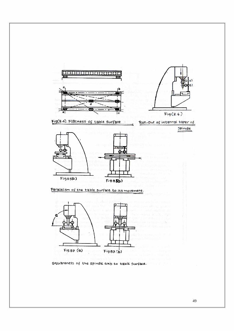
3.4. Flatness of the table surface : Fig (8.4)
Flatness of the table surface is checked by precision level or straight edge and slip gauges. This test is conducted by arranging table and cross-slide in its central position, locking knee and cross - slide and unlocking the table. Maximum permissible deviation is 0.05 mm.
49
50
3.5 Parallelism of the table surface to its movement:
Parallelism of the table surface to its movement in transverse direction and longitudinal direction is checked by straight edge and dial gauge. The dial gauge is mounted on a fixed part of the machine in such a way that the stylus or the feeler is placed approximately at the working position of the tool as shown in fig ( 8.5a & 8.5b ) parallelism of the table surface to its transverse movement is tested by locking table and spindle head slide and parallelism to its longitudinal movement is tested by locking cross slide and spindle head slide. The deviations from parallelism between the table surface and its movement in both directions are noted down. If the table" is uneven, a straight edge may be placed on the surface.
3.6 Run-out of the internal taper of the spindle :
This test is conducted by setting the table in its main position longitudinally and the mandrel of 300 mm long is fixed in the spindle taper. A dial gauge is set on the machine table and the feeler is adjusted to touch the surface of the mandrel as shown in fig( 8.6) The mandrel is then turned and the dial gauge readings at two points are noted i.e., one at the place nearest to spindle nose and other at about 300 mm from it. There can be two errors. i) Axis of the spindle and the axis of taper may not be parallel, ii) Eccentricity of the taper hole which,’ if present, should indicate same error at both the places. The permissible deviation is 0.01-0.02 mm.
3.7. Squareness of the spindle axis to the table surface :
Squareness of the spindle axis to the table surface is checked in two planes by locking spindle head slide, table, cross slide and knee. The dial gauge is set on the machine table. A mandrel 300 mm long is fitted in the spindle taper. The feeler of dial gauges made to touch the surface of the mandrel as shown in fig(8.7 a and 8.7 b). With mandrel in position, the readings at the maximum vertical travel of the table surface is observed at two positions. The permissible error for measurement in two planes is 0.025 mm for 300mm length.
3.8 Squareness of the movement of the table transversely to its longitudinal movement
This test is conducted by setting the straight edge parallel to the table longitudinal movement, then the square shall be placed against the straight edge. The table is locked in central position and dial gauge reading is observed. The dial gauge may be placed on a fixed part of the machine as shown in fig (8.8a & 8.8 b) the permissible deviation is 0.02 mm for 300 mm length.
3.9 Practical Test
Alignment test is performed to see its. dynamic stability, which maybe poor though alignment tests are right, certain specific jobs are prepared and their accuracy is checked.

51
The test piece with dimensions shown in fig (8.9) is prepared on the milling machine as described below.
52
i) Milling of surface B by automatic longitudinal movement of the table and manual vertical movement of the knee, in two cuts overlapping by about 5 to 10mm. ii) Milling of strips of surfaces A, B, C and D by automatic longitudinal movement of the table, automatic vertical movement of the knee and manual transverse movement of the cross - slide.
All surfaces A, B, C and D are checked for its flatness and perpendicularity with respect to each other.
4 PRECAUTIONS:
i) All moving parts of the machine must be locked while reading the dial gauge, ii) If the table surface is uneven, straight edges must be used.
5 REVIEW QUESTIONS:
i) Distinguish between geometric tests and practical tests. ii) How will you measure the flatness of the table surface ? iii) What are the various alignment tests conducted on vertical milling machine ? iv) What are the various measuring instruments used in alignment test of a milling machine v) What are the dimensions of a test piece used in practical test ?

53