methods for reducing frequency and voltage variations on...
TRANSCRIPT
Author’s Name Name of the Paper Session
DYNAMIC POSITIONING CONFERENCE October 9-10, 2012
POWER SESSION
Methods for Reducing Frequency and Voltage Variations on DP Vessels
Eirik Mathiesen, Bjørnar Realfsen and Morten Breivik
Kongsberg Maritime AS

Mathiesen, Realfsen and Breivik Methods for Reducing Frequency and Voltage Variations
DP Conference Houston October 9-10, 2012 Page 1
Abstract This paper considers two methods for reducing frequency and voltage variations in the power distribution system of dynamically positioned vessels. The first method is called Dynamic Load Prediction (DLP) and in short uses predicted future load changes as feedforward to the vessel motor generator set (MGS) controllers. The second method is called Dynamic Load Control (DLC) and in short links together load control and station-keeping control in order to minimize variations of the former by accepting small deviations in the latter. By using these methods, frequency and voltage variations can be reduced such that the number of online MGS can be reduced without the risk of blackout. Reducing the number of MGS in turn results in reduced fuel consumption and emissions, as well as reduced maintenance of the engines.
1. Introduction A dynamic positioning (DP) system is used to automatically control the alongship, athwartship and rotational movement of a vessel. The DP system typically controls the vessel movements by means of thrusters, propellers and rudders. For simplicity, the term thruster will be used for any propulsion means throughout the rest of this paper. Electrically-based power systems are widely used in the maritime world today, in which case the thrusters are electrically driven while power is provided by motor generator sets (MGS) driven by diesel engines, gas turbines, dual-fuel engines, fuel cells, etc. Power is consumed from a power plant with many consumers, where the thrusters are typically dominating. Normally, a high number of MGS are required to be connected to the power plant in order to keep a stable frequency and voltage in the occurrence of consumer load variations from e.g. electric heave compensation, drawwork, winch, crane, thrusters or sudden re-configurations of the distribution system. Frequency and voltage variations can be fatal to the power system and might lead to blackout, fallout of subsystems and synchronization problems for generators which must be connected to the power grid.
Figure 1: It is important to minimize frequency and voltage variations in the power distribution system of dynamically positioned vessels in order to avoid potential blackout or fallout of subsystems.

Mathiesen, Realfsen and Breivik Methods for Reducing Frequency and Voltage Variations
DP Conference Houston October 9-10, 2012 Page 2
There are several benefits associated with reducing the amount of online MGS, such as reduced NOX emissions, reduced sooting, reduced fuel consumption, and reduced maintenance of the engines. Figure 2 confirms that it is more environmentally friendly to run few MGS online at the same time with a high load on each, than many simultaneous MGS with a small load on each. For many years, the offshore industry has desired to reduce the number of online MGS without simultaneously increasing the risk of frequency and voltage variations, but no substantial solutions have been provided so far. In what follows, two new methods are proposed which attempt to address this problem.
Figure 2: Specific Fuel Oil Consumption (SFOC) measured for a typical MGS on a supply vessel. As can be seen, the MGS SFOC efficiency increases significantly with increasing load.
2. Dynamic Load Prediction (DLP) Dynamic Load Prediction (DLP) is a proposed, patent-pending method for reducing frequency and voltage variations which can be induced by many kinds of load changes in a marine power distribution system, e.g. variations in heavy consumer load, equipment failures or controlled changes. An existing method for compensating load variations is exemplified in (Jones and Newton, 2011), where the power supply is controlled based on information about the torque in the motors and e.g. the signals from a DP control system. However, such a solution is reactive, and not proactive, since it relies on already-occurred, measured deviations and power requirements. Hence, a simultaneous rise in the load from one or more consumers may exceed the available power rate limit and therefore result in frequency and voltage reductions. In contrast, a DLP system represents a feedforward solution, comprising a number of prediction functions and a predicted load allocation function with distribution of feedforward values to the MGS controllers, as shown in Figure 3. The objective of the prediction functions is to predict load changes for the MGS, which typically can occur due to the following reasons:
Mathiesen, Realfsen and Breivik Methods for Reducing Frequency and Voltage Variations
DP Conference Houston October 9-10, 2012 Page 3
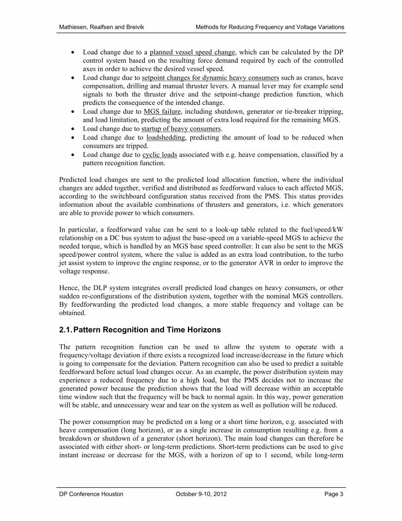
• Load change due to a planned vessel speed change, which can be calculated by the DP control system based on the resulting force demand required by each of the controlled axes in order to achieve the desired vessel speed.
• Load change due to setpoint changes for dynamic heavy consumers such as cranes, heave compensation, drilling and manual thruster levers. A manual lever may for example send signals to both the thruster drive and the setpoint-change prediction function, which predicts the consequence of the intended change.
• Load change due to MGS failure, including shutdown, generator or tie-breaker tripping, and load limitation, predicting the amount of extra load required for the remaining MGS.
• Load change due to startup of heavy consumers. • Load change due to loadshedding, predicting the amount of load to be reduced when
consumers are tripped. • Load change due to cyclic loads associated with e.g. heave compensation, classified by a
pattern recognition function. Predicted load changes are sent to the predicted load allocation function, where the individual changes are added together, verified and distributed as feedforward values to each affected MGS, according to the switchboard configuration status received from the PMS. This status provides information about the available combinations of thrusters and generators, i.e. which generators are able to provide power to which consumers. In particular, a feedforward value can be sent to a look-up table related to the fuel/speed/kW relationship on a DC bus system to adjust the base-speed on a variable-speed MGS to achieve the needed torque, which is handled by an MGS base speed controller. It can also be sent to the MGS speed/power control system, where the value is added as an extra load contribution, to the turbo jet assist system to improve the engine response, or to the generator AVR in order to improve the voltage response. Hence, the DLP system integrates overall predicted load changes on heavy consumers, or other sudden re-configurations of the distribution system, together with the nominal MGS controllers. By feedforwarding the predicted load changes, a more stable frequency and voltage can be obtained. 2.1. Pattern Recognition and Time Horizons The pattern recognition function can be used to allow the system to operate with a frequency/voltage deviation if there exists a recognized load increase/decrease in the future which is going to compensate for the deviation. Pattern recognition can also be used to predict a suitable feedforward before actual load changes occur. As an example, the power distribution system may experience a reduced frequency due to a high load, but the PMS decides not to increase the generated power because the prediction shows that the load will decrease within an acceptable time window such that the frequency will be back to normal again. In this way, power generation will be stable, and unnecessary wear and tear on the system as well as pollution will be reduced. The power consumption may be predicted on a long or a short time horizon, e.g. associated with heave compensation (long horizon), or as a single increase in consumption resulting e.g. from a breakdown or shutdown of a generator (short horizon). The main load changes can therefore be associated with either short- or long-term predictions. Short-term predictions can be used to give instant increase or decrease for the MGS, with a horizon of up to 1 second, while long-term

Mathiesen, Realfsen and Breivik Methods for Reducing Frequency and Voltage Variations
DP Conference Houston October 9-10, 2012 Page 4
predictions can be used to allow frequency and voltage deviations which will be compensated by later load increase or decrease, with a horizon of typically 10-30 seconds.
Figure 3: The DLP system feedforwards predicted load changes to the various MGS controllers in order to reduce frequency and voltage variations in the marine power distribution system.
2.2. Example: DP Thruster Load Predictions The DP system typically uses a piecewise-constant jerk trajectory generator to calculate position, speed and acceleration setpoints for the DP controller. An increase of the velocity setpoint will naturally lead to a change in the acceleration of the vessel. This acceleration demand is converted to power and sent to the DLP. By providing a well-defined acceleration profile, the trajectory generator is therefore well suited for calculating long-term demands for the future. A DP vessel which is drifting away from its position setpoint will have an increasing power demand until the drift is stopped and the vessel again moves toward the desired position. The DP control system can then by mathematical model prediction estimate the maximum power usage associated with the drift off and send the result to the DLP.

Mathiesen, Realfsen and Breivik Methods for Reducing Frequency and Voltage Variations
DP Conference Houston October 9-10, 2012 Page 5
The DP control system may also predict load demand based on environmental measurements such as wind speed and direction, which may affect the position or movement of the vessel, and which is typically a short-term prediction. In addition, the DP control system may run a simulation to analyze blackout on the switchboard sections or loss of thrusters. Such analysis is mandatory on all DP class 2 and 3 vessels, and estimates the power usage on the remaining switchboard sections when one section blacks out. The analysis can also calculate the change in load demand in case of thruster losses or a bus-tie trip, which can be sent to the DLP so that the predicted load allocation function will instantly know the power demand when such events are detected. 2.3. DLP Simulation Figure 4 shows a simulation of a DP vessel with a varying thruster load before and after the DLP system is turned on. It can be clearly seen that the switchboard frequency variations are significantly reduced when using dynamic load prediction.
Figure 4: Turning on the DLP system significantly reduces the switchboard frequency variations.
3. Dynamic Load Control (DLC) Dynamic Load Control (DLC) is another proposed, patent-pending method for reducing frequency and voltage variations in a marine power distribution system, focusing more specifically on drilling vessels with cyclic load variations than DLP. By measuring variations in the dynamic load from heavy consumers such as crane or drawwork, the load changes can be compensated by utilizing a special thrust allocation algorithm in the DP control system. Hence, varying loads from dynamic consumers are compensated for by the
Non-active DLP Active DLP
Mathiesen, Realfsen and Breivik Methods for Reducing Frequency and Voltage Variations
DP Conference Houston October 9-10, 2012 Page 6
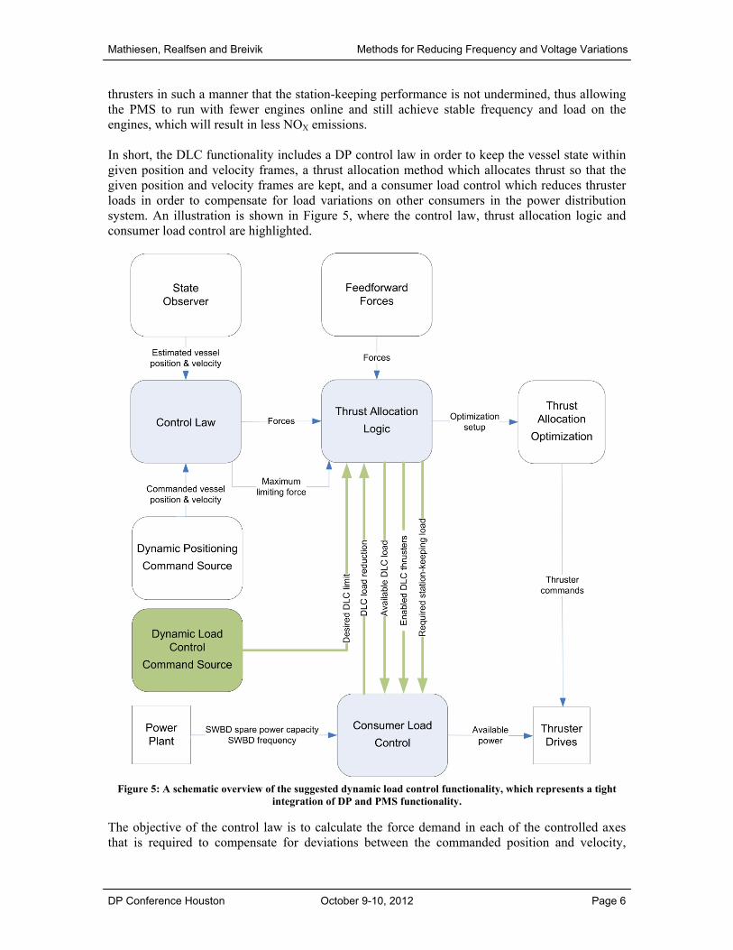
thrusters in such a manner that the station-keeping performance is not undermined, thus allowing the PMS to run with fewer engines online and still achieve stable frequency and load on the engines, which will result in less NOX emissions. In short, the DLC functionality includes a DP control law in order to keep the vessel state within given position and velocity frames, a thrust allocation method which allocates thrust so that the given position and velocity frames are kept, and a consumer load control which reduces thruster loads in order to compensate for load variations on other consumers in the power distribution system. An illustration is shown in Figure 5, where the control law, thrust allocation logic and consumer load control are highlighted.
Figure 5: A schematic overview of the suggested dynamic load control functionality, which represents a tight integration of DP and PMS functionality.
The objective of the control law is to calculate the force demand in each of the controlled axes that is required to compensate for deviations between the commanded position and velocity,

Mathiesen, Realfsen and Breivik Methods for Reducing Frequency and Voltage Variations
DP Conference Houston October 9-10, 2012 Page 7
received from the command source, and the estimated vessel position and velocity, received from the state observer. The thrust allocation optimization module solves a nonlinear optimization problem in order to calculate the thrust magnitude and direction required for each thruster to fulfill the force demand in each axis. The objective for the optimization problem is typically to minimize the total power usage for the thrusters. In DLC mode, the thrust allocation logic separates the thrusters into two groups, one which is to be used for DLC and one which is not. In this regard, a minimum of two freely rotatable (azimuth) thrusters must be available for DLC. If the demanded thrust is sufficiently high, all thrusters will contribute to fulfill the thrust demand from the control law. However, the DLC thrusters will enter a biasing mode if the demanded thrust is so low that the allocated load on each thruster gives no flexibility for DLC. This flexibility in thrust allocation ensures that DLC can be used for a large weather window. The objectives of the consumer load control module are to verify the load for each consumer on a switchboard, and to calculate relevant load limitations for the thrusters in order to compensate for changes in load demand from the other consumers. These limitations must be within frames provided by the thrust allocation logic. The calculations are based on both measured values and mathematical models, where the latter gives the advantage of load prediction in order to obtain fast response for required thruster load changes. The consumer load control can also receive information about planned power consumption or estimate load peaks for other consumers in order to improve the load calculations. The load reduction for each thruster due to DLC is sent from the consumer load control to the thrust allocation logic, where the load is converted to a force loss for each controlled axis and used as input to an averaging filter. The output from the filter is then used as a feedforward demand added to the thrust demand for the non-DLC thrusters. In this way, the thrust allocation will compensate for the average thrust loss caused by the DLC in those cases where the DLC is compensating cyclic load variations, and the DP system will gain increased positioning accuracy. The control law itself is also modified in DLC mode. Suitable tolerance windows are defined for the vessel position and velocity deviations, such that the deviations must exceed the window limits before the controller demands a specific compensating thrust. These windows serve two main purposes, i.e.
1) to avoid load variations caused by the DLC-induced position and velocity deviations, giving a tolerable slack for the positioning accuracy which depends on the installed equipment and vessel operation, and
2) to calculate force deviation limits which are sent to the thrust allocation logic. Based on these limits and the allocated thrust, the allocation logic calculates the available DLC load for each thruster, which is sent to the consumer load control to adjust the thruster load correspondingly. The basic concept of DLC can of course be implemented without integration of DP and PMS functionality, but will then typically result in drift or drive off situations due to the excessive thrust noise created by the load compensation. In order to maintain high station-keeping quality in combination with such compensation, the solution proposed in this paper has a high level of integration between the DP system and the PMS, as illustrated in Figure 5.
Mathiesen, Realfsen and Breivik Methods for Reducing Frequency and Voltage Variations
DP Conference Houston October 9-10, 2012 Page 8
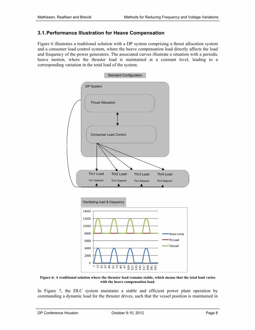
3.1. Performance Illustration for Heave Compensation Figure 6 illustrates a traditional solution with a DP system comprising a thrust allocation system and a consumer load control system, where the heave compensation load directly affects the load and frequency of the power generators. The associated curves illustrate a situation with a periodic heave motion, where the thruster load is maintained at a constant level, leading to a corresponding variation in the total load of the system.
Figure 6: A traditional solution where the thruster load remains stable, which means that the total load varies with the heave compensation load.
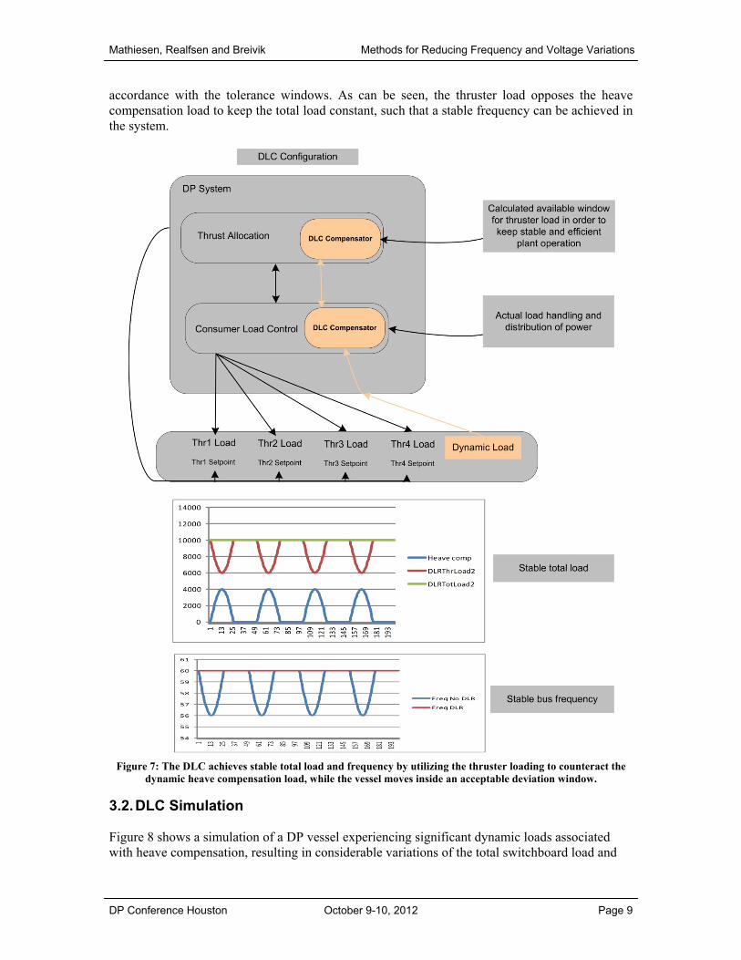
In Figure 7, the DLC system maintains a stable and efficient power plant operation by commanding a dynamic load for the thruster drives, such that the vessel position is maintained in
Mathiesen, Realfsen and Breivik Methods for Reducing Frequency and Voltage Variations
DP Conference Houston October 9-10, 2012 Page 9
accordance with the tolerance windows. As can be seen, the thruster load opposes the heave compensation load to keep the total load constant, such that a stable frequency can be achieved in the system.
Figure 7: The DLC achieves stable total load and frequency by utilizing the thruster loading to counteract the dynamic heave compensation load, while the vessel moves inside an acceptable deviation window.
3.2. DLC Simulation Figure 8 shows a simulation of a DP vessel experiencing significant dynamic loads associated with heave compensation, resulting in considerable variations of the total switchboard load and

Mathiesen, Realfsen and Breivik Methods for Reducing Frequency and Voltage Variations
DP Conference Houston October 9-10, 2012 Page 10
frequency. Turning on the DLC system, making the DLC thrusters relieve the drawwork load, these variations are seen to be significantly reduced.
Figure 8: Activating the DLC system significantly reduces the switchboard load and frequency variations.
4. Conclusion This paper has considered two new methods for reducing frequency and voltage variations in the power distribution of dynamically positioned vessels. While DLP uses predicted future load changes as a feedforward to the vessel MGS controllers, DLC links together load control and station-keeping control in order to minimize variations of the former by accepting small deviations in the latter. Simulation results illustrate the performance of the proposed methods. By using DLP and DLC, frequency and voltage variations can be reduced such that the number of online MGS can be lowered without the risk of blackout. Reducing the number of MGS in turn results in reduced fuel consumption and emissions, as well as reduced maintenance on the engines, which is both environmentally friendly and saves money for the vessel operator. Also, while DLP is relevant for all types of DP vessels, DLC is mostly relevant for DP vessels experiencing cyclic load variations such as e.g. drill rigs. Finally, both methods will typically only require a software upgrade, with no need to install any new equipment.
References R. Jones and C. Newton, "Power Converters". U.S. Patent 8,008,885, issued August 30, 2011.
Non-active DLC Active DLC