methods for antenna frequency control and user effect
TRANSCRIPT

ABCDEFG
UNIVERS ITY OF OULU P.O.B . 7500 F I -90014 UNIVERS ITY OF OULU F INLAND
A C T A U N I V E R S I T A T I S O U L U E N S I S
S E R I E S E D I T O R S
SCIENTIAE RERUM NATURALIUM
HUMANIORA
TECHNICA
MEDICA
SCIENTIAE RERUM SOCIALIUM
SCRIPTA ACADEMICA
OECONOMICA
EDITOR IN CHIEF
PUBLICATIONS EDITOR
Senior Assistant Jorma Arhippainen
Lecturer Santeri Palviainen
Professor Hannu Heusala
Professor Olli Vuolteenaho
Senior Researcher Eila Estola
Director Sinikka Eskelinen
Professor Jari Juga
Professor Olli Vuolteenaho
Publications Editor Kirsti Nurkkala
ISBN 978-951-42-9690-1 (Paperback)ISBN 978-951-42-9691-8 (PDF)ISSN 0355-3213 (Print)ISSN 1796-2226 (Online)
U N I V E R S I TAT I S O U L U E N S I SACTAC
TECHNICA
U N I V E R S I TAT I S O U L U E N S I SACTAC
TECHNICA
OULU 2011
C 410
Markus Berg
METHODS FOR ANTENNA FREQUENCY CONTROL AND USER EFFECT COMPENSATION IN MOBILE TERMINALS
UNIVERSITY OF OULU,FACULTY OF TECHNOLOGY, DEPARTMENT OF COMMUNICATIONS ENGINEERING;CENTRE FOR WIRELESS COMMUNICATIONS;INFOTECH OULU
C 410
ACTA
Markus B
erg
C410etukansi.kesken..fm Page 1 Tuesday, November 8, 2011 10:39 AM


A C T A U N I V E R S I T A T I S O U L U E N S I SC Te c h n i c a 4 1 0
MARKUS BERG
METHODS FOR ANTENNA FREQUENCY CONTROL AND USER EFFECT COMPENSATION IN MOBILE TERMINALS
Academic dissertation to be presented with the assent ofthe Faculty of Technology of the University of Oulu forpublic defence in Auditorium PR102, Linnanmaa, on 9December 2011, at 12 noon
UNIVERSITY OF OULU, OULU 2011

Copyright © 2011Acta Univ. Oul. C 410, 2011
Supervised byDoctor Erkki T. Salonen
Reviewed byProfessor Pertti VainikainenDoctor Jani Ollikainen
ISBN 978-951-42-9690-1 (Paperback)ISBN 978-951-42-9691-8 (PDF)
ISSN 0355-3213 (Printed)ISSN 1796-2226 (Online)
Cover DesignRaimo Ahonen
JUVENES PRINTTAMPERE 2011

Berg, Markus, Methods for antenna frequency control and user effectcompensation in mobile terminals University of Oulu, Faculty of Technology, Department of Communications Engineering;Centre for Wireless Communications; Infotech Oulu, P.O. Box 4500, FI-90014 University ofOulu, FinlandActa Univ. Oul. C 410, 2011Oulu, Finland
Abstract
In this thesis, new methods for mobile terminal antenna frequency control and user effectcompensation are presented. The thesis is divided into two parts. The first part includes frequencyreconfigurable and tuneable antennas for mobile terminals. At first, the efficient frequencyreconfiguration methods for a slot-, planar inverted-F (PIFA) and inverted-F (IFA) antennas arepresented. Methods are based either on the use of RF switches, or on variable capacitor loading.One of the frequency tuneable antennas is used for the antenna frequency bandwidth enhancementin an internal digital television reception antenna, offering a continuous tunability range from470 MHz to 702 MHz with 8 MHz instantaneous bandwidth.
The second part of this thesis is concentrated on the user effect on the mobile terminalantennas, and especially, on the active compensation of the user-induced losses. At first, anexperimental user effect study is conducted for triple-band PIFA and the body loss, comprisingboth the reflection loss and absorption loss, is characterized and formulated. It was observed thatwith the highly loaded mobile terminal antenna the majority of the losses are absorption losses andthe user-induced reflection losses play a minor role.
An active method of compensating the body loss, and especially the absorptive part of it, isdesigned and developed in this thesis. The switchable two-antenna arrangement is applied to adual-band top-bottom PIFA that yielded up to 9 dB compensation of the body loss with a specificphantom hand grips in the lower band (GSM 850). In the higher band (GSM 1900 and WCDMA)2 dB compensation is obtained.
The same method is verified with two side by side-located PIFA and monopole configurationsin order to compensate the effect of the user’s index finger. The losses from switching circuitryproved to be smaller than the benefit achieved by the compensation method.
Keywords: body loss, frequency-tuneable antennas, mobile antennas, user effectcompensation


Berg, Markus, Menetelmiä matkaviestinantennin taajuussäätöön ja käyttäjänvaikutuksen kompensointiin Oulun yliopisto, Teknillinen tiedekunta, Tietoliikennetekniikan osasto; Centre for WirelessCommunications; Infotech Oulu, PL 4500, 90014 Oulun yliopistoActa Univ. Oul. C 410, 2011Oulu
TiivistelmäTässä työssä esitään uudenlaisia menetelmiä matkaviestinantennin taajuussäätöön ja käyttäjänvaikutuksen kompensointiin. Työ jakautuu kahteen osaan, joista ensimmäisessä käsitellään taa-juussädettäviä matkaviestinantenneja. Aluksi esitetään tehokkaita taajuussäätömenetelmiä rako-,tasomainen käännetty-F- ja käännetty-F -tyyppisille antennirakenteille. Menetelmät perustuvatjoko RF kytkimen tai säädettävän kapasitanssin käyttöön. Yhtä säätömenetelmää sovelletaanpäätelaitteen sisäisen vastaanottoantennin taajuuskaistanleveyden kasvattamiseen. Säätömenetel-mällä saavutettu jatkuva säätöalue on 470–702 MHz ja hetkellinen kaistanleveys on 8 MHz.
Työn toisessa osassa keskitytään käyttäjän matkaviestimen antennille aiheuttamaan vaikutuk-seen ja erityisesti käyttäjän aiheuttamien häviöiden kompensointiin. Aluksi esitetään kokeelli-nen tutkimus käyttäjän vaikutuksesta kolmikaistaiseen PIFA-antenniin. Tutkimuksessa arvioi-daan kehohäviöiden määrää, antennin impedanssimuutoksesta aiheutuvaa heijastushäviötä jaabsorptiohäviötä. Tutkimuksen perusteella absorptiolla on suurempi vaikutus kokonaishäviöönkuin heijastushäviöllä.
Työssä esitetään aktiivinen kehohäviön ja erityisesti absorptiohäviön kompensointimenetel-mä. Menetelmässä antennikytkentää sovelletaan päätelaitteen ylä- ja alapäähän sijoitettuihinkaksitaajuus antenniin. Tutkimuksen perusteella todetaan, että tietyn käsiotteen aiheuttamiahäviöitä voidaan kompensoida 9 dB matalammalla taajuuskaistalla (GSM 850) ja 2 dB korkeam-malla taajuuskaistalla (GSM 900 ja WCDMA).
Kompensointimenetelmän toimivuus todennetaan myös kahdella monopoli- ja PIFA-antenni-rakenteella käyttäen erilaista antennijärjestelyä, jossa pääpaino on käyttäjän etusormesta johtu-vien häviöiden kompensoinnissa. Antennikytkennän aiheuttamat häviöt ovat pienemmät kuinkompensointimenetelmällä saavutettu etu.
Asiasanat: kehohäviöt, käyttäjävaikutuksen kompensointi, matkapuhelinantennit,taajuusviritettävät antennit


7
Acknowledgements
Firstly, I want to thank my supervisor Dr. Erkki Salonen for the interesting
research topic for my thesis. I am very grateful to him for enthusiastic instructions
and encouragement throughout my postgraduate studies.
My present and former research colleagues, Dr. Mikko Komulainen, M.Sc.
Marko Sonkki, M.Sc. Sami Myllymäki, M.Sc. Arttu Huttunen, M.Sc. Emmi
Kaivanto and M.Sc. Tommi Tuovinen deserve my greatest thanks for co-operation
and an inspiring research atmosphere.
I want to thank Professor Dr. Heli Jantunen for her support during the
common project work. Also, I am grateful for the technical and theoretical
discussions with Dr. Seppo Karhu and M.Sc. Juha Pihlaja, which have increased
my understanding in the fundamental antenna questions.
In the year 2011 the work was financially supported by Infotech Oulu
Graduate School. The Emil Aaltonen Foundation, the Finnish Foundation for
Technology Promotion, the Jenny and Antti Wihuri Foundation and the Tauno
Tönning Foundation are acknowledged for supporting the work.
In the end, I want to thank my wife Anna-Kaisa for her understanding and
endless support for my research work. She and our three girls and five boys have
reminded me that the most important things are somewhere else than at my desk.
Oulu, November 02, 2011 Markus Berg

8

9
List of abbreviations and definitions
4G 4th generation
BL Body loss
BW Bandwidth
dB decibel
dBm decibels referred to 1 mW
DC Direct Current
DVB-H Digital Video Broadcasting Handheld
EM Electromagnetic
HAC Hearing Aid Compatibility
IFA Inverted-F Antenna
IIP3 Third-Order Input Intercept Point
LTE-A Long Term Evolution - Advanced
MEG Mean Effective Gain
MEM Micro Electro Mechanical
MIMO Multiple Input Multiple Output
PA power amplifier
PIFA Planar Inverted-F Antenna
PCB Printed Circuit Board
RX Receive
SAR Specific Absorption Loss
SMD Surface Mount Device
SPDT Single Pole Double Throw
SPST Single Pole Single Throw
SPTT Single Pole Triple Throw
TIS Total Isotropic Sensitivity
TRP Total Radiated Power
TX Transmit
UHF Ultra High Frequency
VNA Vector Network Analyzer
WCDMA Wideband Code Division Multiple Access
λ lambda, wavelength
Γ gamma, reflection coefficient
ε permittivity
ε’ real part of permittivity

10
ε’’ imaginary part of permittivity
εr relative permittivity
εeff effective permittivity
ε0 permittivity of vacuum
σ conductivity
ω angular frequency
ρ tissue density
μ0 permeability of vacuum
tan δ loss tangent
c velocity of light
CDC DC block capacitor
Cv variable capacitor
D largest dimension of antenna
erad radiation efficiency
erefl reflection efficiency
etot total efficiency
etot,fs total efficiency in free space
etot,user total efficiency with user
|E
| rms electric field
f frequency
fs resonance frequency
I current
j imaginary unit
k wave number
Labs body absorption loss
Lreflection reflection loss
Q quality factor
QR,min smallest radiation quality factor
r radiansphere enclosing the antenna
Rnear-field reactive near field
S11 reflection coefficient
V voltage
Zin input impedance
Z0 characteristic impedance

11
List of original publications
The thesis is based on the following seven papers, which are cited in the text by
their Roman numerals.
I Berg M, Komulainen M, Salonen E & Jantunen H (2006) Frequency reconfigurable microstrip-fed annular slot antenna. Proc European Conference on Antennas and Propagation. Nice, France: 1−6.
II Berg M, Komulainen M, Palukuru V, Jantunen H & Salonen E (2007) Frequency-tunable DVB-H antenna for mobile terminals. Proc IEEE Antennas and Propagation International Symposium. Honolulu, USA: 1072−1075.
III Komulainen M, Berg M. Mähönen J. Jantunen H & Salonen E. (2006) Frequency reconfigurable planar inverted-F antennas for portable wireless devices. Proc European Conference on Antennas and Propagation. Nice, France: 1−6.
IV Berg M, Sonkki M & Salonen E (2009) Experimental study of hand and head effects to mobile phone antenna radiation properties. Proc European Conference on Antennas and Propagation. Berlin, Germany: 437−440.
V Berg M & Salonen E (2011) Compensating the influence of human hand with two switchable antennas. IET Microwaves, Antennas & Propagation: In press
VI Berg M & Salonen E (2010) Control system for compensation of antenna mistuning and absorption caused by user’s index finger. Proc European Conference on Antennas and Propagation. Barcelona, Spain: 1−5.
VII Berg M, Sonkki M & Salonen E (2011) Absorption loss reduction in a mobile terminal with switchable monopole antennas. IEEE Transactions on Antennas and Propagation. 59(11): 4379−4383.
An efficient antenna frequency control method with a high frequency shift in
Paper I was completely developed by the author. Co-author contribution consisted
of the verification of the obtained results and writing of the paper.
In Paper II, the idea, the design and the experimental work on frequency
tuneable antenna development are mostly contributed by the author of this thesis.
The co-authors assisted in antenna design, manufacturing and writing the paper.
The main responsibility of the writing was carried out by the author.
One of the two developed frequency reconfiguration methods presented in
Paper III was originally developed by the author. Another method was developed
by the first author.
The experimental user effect study in Paper IV was mainly designed and
carried out by the author. This includes antenna design, actual measurements and
data processing. Contribution of the co-authors was in the area of measurement
setup definition, verifying the equations used and assisting the writing process.

12
The idea of the control system for compensation of the hand effect (Papers V,
VI, and VII) was originally developed by the author. The development of the
system, data analysis and writing was carried out in cooperation with the co-
authors.
Other related publications co-authored by this author can be found in the
reference list as [40], [41] and [58].

13
Table of contents
Abstract
Tiivistelmä
Acknowledgements 7 List of abbreviations and definitions 9 List of original publications 11 Table of contents 13 1 Introduction 15
1.1 Background and research environment ................................................... 15 1.2 Objectives and scope ............................................................................... 16 1.3 Materials and methods ............................................................................ 18
2 Theoretical foundation 21 2.1 Fundamental limitations of mobile terminal antennas ............................ 21 2.2 Effect of human tissue on electromagnetic field ..................................... 24 2.3 Frequency reconfigurable antennas ......................................................... 25 2.4 User influence on mobile terminal antennas ........................................... 27 2.5 User effect compensation techniques ...................................................... 31
3 Frequency reconfigurable antennas 37 3.1 Classification of frequency controlling methods .................................... 37
3.1.1 External matching circuit ............................................................. 37 3.1.2 Switchable feed / short ................................................................. 39 3.1.3 Resonance tuning of the antenna element .................................... 41
3.2 Discussions ............................................................................................. 47 4 User influence on triple resonance PIFA 49
4.1 Experimental arrangements ..................................................................... 49 4.2 Hand- and head-induced body loss ......................................................... 51 4.3 Discussions ............................................................................................. 53
5 Active user effect compensation in mobile terminal antennas 55 5.1 Dynamically switchable antenna arrangements ...................................... 55
5.1.1 Top - bottom arrangement ............................................................ 55 5.1.2 Two top-located PIFAs ................................................................. 58 5.1.3 Two top-located monopoles.......................................................... 61
5.2 Discussion ............................................................................................... 62 6 Summary of publications 65 7 Conclusions 69 References 73

14
Original publications 81

15
1 Introduction
1.1 Background and research environment
An antenna is an essential part of the wireless radio frequency communication
system. It works as a transformer between the guided electromagnetic wave inside
the terminal and wave propagating in the air. Thus, every wireless portable device
having data transmission capability that uses electromagnetic waves must have at
least one antenna.
The development of wireless communication systems has been very rapid
during the past decade. New wireless communication systems and standards, for
example 4G Long Term Evolution - Advanced (LTE-A) and Digital Video
Broadcasting - Handheld (DVB-H), have characteristics that diverge from the
previous systems from the mobile terminal antenna point of view [1], [15]. The
most essential parameters are related to the antenna efficiency, operation
frequencies and frequency bandwidth (BW) used.
The increasing number of different communication systems has led to the
increased number of internal antennas in one terminal. Conventional mobile
terminal antennas are the resonance type of antennas which have fundamental
limitations between their size, efficiency and attainable frequency BW [12], [101].
Since the space for antennas is limited in mobile terminals, the final antenna is the
product of the trade-off between performance and size. Multiple resonance
techniques have been used to enhance the frequency BW of one antenna to cover
several system frequency requirements [18].
Recently, new BW enhancement techniques have been developed, including
terminal antenna frequency controlling [39], [54] and [84]. Depending on the
communication system, frequency controllable antennas provide a feasible
solution with a performance level difficult to attain with conventional antennas.
However, the frequency control increases the terminal antenna complexity and
cost.
The first part of this thesis focuses on the development of efficient frequency
control methods. One developed method is implemented into an internal terminal
antenna, thus applicable to DVB-H reception.
Another topic of this thesis is related to interaction between the user and
mobile terminal antenna. Human tissue in close proximity to a mobile terminal
antenna is known to reduce antenna efficiency. The main reasons for the

16
efficiency decrease is impedance mistuning between antenna and RF electronics,
and absorption to the user’s head & hand [6], [30].
The user-induced efficiency decrease is typically compensated for by
increasing the transmit power level of the terminal at the expense of higher power
consumption. The transmit power is automatically adjusted to maintain acceptable
signal quality between the terminal and the base station [89]. Consequently,
power dissipated to human tissue increases. In order to avoid the unnecessary
increase in power usage, or even connection failure, different ways to compensate
for the user-induced efficiency decrease are required.
User-induced body loss (BL), including impedance mismatch and body
absorption losses, is studied in this thesis. In addition, a user effect compensation
method comprising dynamically switchable antennas is developed, implemented
and verified by measurements. Switchable antennas used are dual-band structures
including frequencies near 900 MHz and 1800 MHz.
1.2 Objectives and scope
The topic of this doctoral thesis is in the area of more functional mobile terminal
antennas. The thesis is focused on increasing the functionality of antennas by
different antenna control methods. In more detail, the topic is divided into the
development of 1) frequency control and 2) user effect compensation methods for
mobile terminal antennas. Both topics are closely related to the challenges of the
current and future wireless telecommunication systems.
The antenna impedance BW enhancement is discussed in Chapter 3. The
main focus has been on the development of the efficient antenna frequency
control methods for mobile terminals. In practice, two different methods are
developed and verified. The first method is applied to the annular slot antenna.
The second method is used in the lower part of the Ultra High Frequency (UHF)
band, covering the frequencies of the DVB-H system. In cases where GSM 900 is
used in a terminal, the frequency range used is from 470 MHz to 698 MHz
because of the high transmission (TX) power of the GSM system [15].
Conventional resonance-type mobile terminal antennas are narrowband in nature
and thus are not applicable to DVB-H signal reception over the wide frequency
range needed. The reception antenna should have a relative BW of 40% to cover
the required frequency range.
The starting point for the antenna BW enhancement study is formulated as
the following research questions:

17
1. What is the efficiency of an antenna frequency tuning method?
2. How can a functional frequency tuning system in an integrated mobile
terminal antenna be design and implement?
The user hand- and head-induced performance decrease has been discussed in
Chapter 4.2. Some knowledge of the terminal antenna performance in usage
situations was found [37], however, e.g., studies related to the effect of the
different user hand grips on the antenna performance were not available. The
object was to experimentally evaluate the amount of user-induced losses with a
typical Planar Inverted-F Antenna (PIFA) by using a phantom head and hand. It
was known that loss is caused by absorption into the head and hand as well as by
the impedance mismatch caused by the vicinity of the user. The contribution of
impedance reflection loss (Lreflection) and body absorption loss (Labs) to the total
body loss (BL) was not earlier examined. In order to get acquainted with the
problem field, the next research questions were defined:
3. What is the amount of the user-induced loss for the mobile terminal antennas?
4. What are the loss types and their contribution to the total user-induced body
loss?
The effect of antenna location on the BL is also studied in Section 5.1.1 with a
dual-band antenna. This phase of the study aimed to clarify whether a new multi
antenna arrangement can reduce the user effect, compared with a single antenna
solution. The studied multi antenna solution included placing switchable antennas
both at the top and the bottom of a mobile terminal. The user hand-induced
performance deterioration was measured with a near-field antenna measurement
system, using a commercial hand phantom to model four different hand grips.
This part of the thesis aimed to answer the question:
5. Can a new switchable multi-antenna solution reduce the user effect?
In the last part of the thesis (Sections 5.1.2 and 5.1.3), the objective was to
develop an antenna arrangement and a control system that decreases the losses
caused by the user of the mobile terminal. The previously presented and discussed
research results have been utilized in order to develop a new compensation
method. The method was implemented with PIFA and monopole-type antennas
designed for 900 MHz and 1900 MHz frequency bands. The performance was
again verified by measurement. Control system research is compressed into the
question:

18
6. Is it possible to compensate for the body loss (BL) by two top-located and
switchable mobile terminal antennas?
The aspects related to the effect of the mobile terminal antenna on health issues
are outside the scope of this research. The approach to the problem is more from
the antenna performance point of view. Therefore the specific absorption rate
(SAR) values of the mobile terminal antennas have not been examined in this
thesis.
1.3 Materials and methods
The research work of this thesis was started by literature review. Information
related to antenna frequency control and user effect on antennas, as well as user
effect compensation methods, was explored from the patent databases [67],
scientific proceedings [29] and from antenna-related books [5], [21]. The first
antenna designs were started with a commercial 3D Electromagnetic (EM) field
simulation tool, CST Microwave Studio®, after initial data collection and
analysis.
Design work was based on the use of 3D Electromagnetic field simulation
tools. The simulation model of an antenna was built into a simulation
environment and it was optimized to the desired frequency bands. Parametric
sweeps speeded up the design process and several iteration rounds were avoided.
In addition, the frequency control system and user effect compensation systems
were modelled by using lumped network elements. Operation of control
components (RF switches and variable capacitors) was included in simulations,
thus enabling the functional model of the final prototype. Surface mount devices
(SMD), inductors and capacitors needed in the antenna impedance matching and
DC isolation, were also included in the simulations. All the developed control
methods were implemented into the antenna prototypes.
The physical limitations to mobile terminal antennas were taken into account.
The size of antenna structures including a ground plane was
40-50 mm × 100 mm × 10 mm that corresponds to the size of a mobile terminal.
A typical antenna prototype consisted of a ground plane made of copper plated
Printed Circuit Board (PCB) material and an antenna made of a metal sheet. Other
RF components were used depending on the solution.
The constructed antenna prototypes were utilised for analysing the influence
of different hand grips on antenna performance. The user hand-induced

19
performance change was measured with a near-field antenna measurement system
and Vector Network Analyzer (VNA). Actual measurements were conducted
using commercial hand phantoms to model different hand grips. A plastic case
was used during measurements to avoid contact between the hand phantom and
the metal parts of the prototype.
Antennas were evaluated in terms of radiation efficiency and reflection loss
with different hand grips. To achieve accurate loss evaluation, both the S11 and
total efficiency measurements were done at the same time with one hand grip.
Performance was studied with different usage situations at the frequency bands of
the existing wireless telecommunication systems including GSM 850, GSM 900,
GSM 1800, GSM 1900 and WCDMA.

20

21
2 Theoretical foundation
This research consists of frequency controllable mobile terminal antennas, user
influence on antennas, and compensation of user-influenced losses. In the
beginning, some fundamental limitations related to mobile terminal antennas are
reviewed and discussed. The theoretical background of the mobile terminal
antenna is presented using generally accepted terms and definitions. Also, the
effect of lossy material on antenna operation is theoretically discussed.
After that, the most significant frequency tuning and controlling methods
published in the scientific literature are presented for the base of the first part of
the thesis. Emphasis has been put on the methods that are applicable to mobile
terminal antennas.
Next, user influence on mobile terminal antennas is comprehensively
discussed, including the latest scientific results. The losses influenced by the user
are reviewed with the mathematical formulation appearing in the scientific
literature.
The last part of the theoretical foundation includes a review of the existing
user effect compensation methods. Because of the relatively new research field,
most of the introduced compensation methods are passive or related to the
correction of the mistuned antenna impedance.
2.1 Fundamental limitations of mobile terminal antennas
Modern mobile terminals are small devices and include several wireless systems.
The size and form of terminals as well as the battery, display and other essential
components restrict the volume available for antennas. These conditions lead to
the situation, where the maximum antenna length is small, typically much less
than one wavelength (λ). Hence, mobile terminal antennas are small and have
properties different from antennas with the length of one wavelength or more.
Fundamental theory for small antennas has been developed decades ago [12],
[16] and [101]. For comprehension, the most important fundamental limitations
are reported here.
Antenna input impedance refers to the impedance presented by the antenna at
its terminals [28]. Impedance Zin is defined as the ratio of voltage (V) to the
current (I)
in
VZI
= . (1)

22
The voltage reflection coefficient Γ of the antenna is defined as
0
0
in
in
Z ZZ Z
Γ −=+
,
where Z0 is the characteristic impedance of the transmission line [5]. The
scattering parameter S11 is referred to as an input reflection coefficient because it
refers to reflection that occurs in port 1 only. Antenna impedance matching is
typically presented as a function of frequency by using the measured S11 values.
The bandwidth (BW) of an antenna is defined in [28] as follows: ”The range
of frequencies within which the performance of the antenna, with respect to some
characteristic, conforms to a specified standard.” The operation frequency range
of a mobile terminal antenna is commonly defined in terms of antenna efficiency
BW. This is a range where the antenna is capable of accepting power and
transforming it into a radiation field. Antenna impedance BW limits can be
defined by using reflection coefficient S11 below a certain threshold, e.g.
S11 < −10 dB.
The quality factor (Q) is defined as a ratio of the energy stored in the antenna
near field to the energy radiated and dissipated per cycle [28]. Near resonance, the
behaviour of small antennas can be presented by equivalent circuit [61].
Therefore, antenna BW can be simply presented by the Q-factor [107]. Based on
the fundamental theory, the smallest radiation quality factor (QR,min) of single
resonant and linearly polarized small antenna can be expressed as
( ),m in 3
1 1RQ krkr
= + , (3)
where r is the smallest radian sphere enclosing the antenna and k is the wave
number. By considering Eq. 3, it is observed that the smaller r is, the higher is the
antenna radiation Q. For linear and passive antennas possibly matched by linear
passive circuits, the quality factor and impedance BW are inversely proportional
to each other [107].
In consequence of the small antenna theory, certain limitations arise from the
mobile terminal antenna point of view. The main issue is the dependence between
the antenna volume and the maximum attainable impedance bandwidth [53]. In
practise, the mobile terminal antenna has impedance BW limitations resulting
from the limited antenna volume inside the terminal.
Present and forthcoming mobile telecommunication standards define the
operation frequency ranges of the systems, e.g. [1] and [15]. The continuous

23
increase in the data transfer rate has affected the antenna BW requirements. The
trend has been not only toward a wider frequency BW but also toward wider
relative BW.
Several methods including parasitic element stacking [63], incorporated
shorting posts [99], reshaping [97], loading with resistor [103] and dual resonance
matching circuits [102], [96] are used to enhance BW of mobile terminal antennas.
Also, BW broadening techniques including wave traps in the terminal ground
plane [50], adding a planar parasitic element and varactor tuning [98] are
proposed. The other way around, antenna volume can be reduced by using
bandwidth-enhancing techniques [13], [81] thus maintaining the original
frequency bandwidth. The latest trend has been in the development from the
resonance type of antennas toward non-resonant coupling element-based
structures [92].
The performance of the different mobile terminal antennas and their
configurations are analysed and compared by using antenna efficiency discussed
in this section. Total efficiency etot is one of the key antenna performance
parameters, including input impedance reflection efficiency erefl and radiation
efficiency erad (see Eq. 4) [5]
to t refl rade e e= . (4)
Radiation efficiency (erad) is defined as the ratio of the total power radiated by an
antenna to the power accepted by the antenna from the connected transmitter [28].
Total efficiency (etot) is the relationship between the radiated power and the power
transmitted to the antenna connector. Total efficiency can be written as
( )2
111tot rade e S= − , (5)
where (1 − |S11|2) is the impedance mismatch factor corresponding impedance
reflection efficiency (erefl) [5]. Later on, in the context of user influence, the
antenna reflection loss (Lreflection) is used instead of reflection efficiency. Antenna
reflection loss is defined as
( )2
10 1110 log 1reflectionL S= − × − , (6)
thus being easily comparable with other losses presented later in the logarithmic
scale.

24
2.2 Effect of human tissue on electromagnetic field
Conventionally antenna parameters, such as impedance bandwidth and efficiency
are defined for the antenna located in free space. Mobile terminal antennas are
used in environments comprising the free space and lossy medium, which is
typically human tissue. For this reason, it is important to discuss parameters that
describe wave behaviour in lossy medium.
The complex permittivity ε of the medium is defined as
' ''jε ε ε= − , (7)
where ε’ is the real part of permittivity that describes the stored energy in the
medium [75, p. 9–11]. The imaginary part ε’’ accounts for loss in the medium due
to damping of vibrating dipole moments. Permittivity is usually scaled to that of
the vacuum and expressed as relative permittivity as follows
0
'r
εεε
= , (8)
where ε0 is 8.854 × 10⁻¹² F/m. Loss tangent defines the loss caused by the
dissipation of the energy to the lossy medium and is expressed as
''
tan'
ωε σδωε
+= , (9)
where ω = 2πf is the angular frequency and σ is conductivity.
When the antenna is located close to human body, the effective wavelength
deviates from the free space wavelength. This is typically observed as a shift of
the antenna resonance frequency. The permittivity affects the antenna resonance
frequency fr as
reff
cfε λ
= , (10)
where c is the velocity of light and λ is the wavelength. The effective permittivity
εeff seen by the antenna depends on the distance between the antenna and the body.
Another interesting issue is the wave penetration into the human tissue. For
an incoming plane wave, the penetration depth δp is given by
( )20 0
1
'1 tan 1
2
pδμ ε εω δ
= + −
, (11)

25
where μ0 = 4π × 10−7 N/A2 is the permeability of the vacuum [82, p. 26]. For
the brain tissue simulating liquid used in the phantom head measurements in
paper [IV], the calculated penetration depth δp = 5.3 cm at 835 MHz. Permittivity
and conductivity values of εr = 48 and σ = 0.70 S/m are used for the calculation.
In the case of an antenna close to the head, the tissue is assumed to be in the
reactive near field of the antenna and therefore the plane wave approximation
does not correspond to the real situation.
In practise, the electromagnetic power originated from the mobile terminal
and absorbed by human tissue is described by SAR values. SAR is defined as the
power absorbed by the tissue per unit of mass and is related with the electric field
2
SAR Eσρ
=
, (12)
where ρ is the tissue density [kg/m3] and |E
| refers to the rms electric field value
[82].
2.3 Frequency reconfigurable antennas
Due to invariably developed telecommunication standards, the number of
dissimilar radio systems in one mobile terminal has increased rapidly. As the
number of systems working at different frequency bands increases, the need for
several antennas increases, too. The space reserved for antennas inside a terminal
is not increased and, nevertheless, much more antennas should be possible to
integrate in terminal.
The fundamental limitations for antenna performance versus antenna size
have yielded the situation where new actions in antenna design are starting to be
evaluated. In addition to the previously mentioned BW enhancing techniques, one
possible solution to the limited BW problem is to use reconfigurable antennas that
can be tuned to different frequency bands [3]. Frequency reconfigurable and
frequency tuneable antennas are able to exceed fundamental BW limitations for
single resonant and passive small antennas (Eq. 3) by providing several
instantaneous frequency bands.
Frequency tuneable antennas have been developed and proposed for mobile
terminal antennas [41], [46], [54] and [64]. Reconfigurable mobile terminal
antennas are typically implemented using semiconductor or Micro Electro
Mechanical (MEM) switches that control the RF current paths in the antenna
element. A frequency tuneable dual-band monopole antenna that covers GSM 850

26
MHz and 1800 MHz bands in one state and GSM 900 MHz and 1900 MHz bands
in the other state is implemented by PIN switches [90]. Two instantaneous
frequency bands mean virtually much higher frequency bandwidth. In [39], it is
found that impedance BW of conventional PIFA- and monopole-type mobile
terminal antennas can be enhanced without losing antenna performance.
Enhancement is implemented using commercial RF switches attached to the
modified antenna element. However, the complexity of the antenna system
increases.
Different adaptive antenna impedance matching options are classified in [26]
including: a) the resonance tuning of the antenna element, b) switching between
different feed points and c) an external switchable matching circuit. The external
tuning circuit typically includes a switched capacitor bank [88], two or more
switchable RF paths with different LC parameters [26] or voltage-controlled
variable capacitances [25], [84].
Mobile terminal antennas can be roughly divided into two different groups.
The first is TX / RX antennas, which are used in two-way data transmission in a
cellular network or in peer-to-peer type communication. The second group is RX
antennas used in radio or television broadcast reception and in satellite navigation
signal reception. From the antenna frequency controlling point of view, antennas
in these two groups have different requirements. The fundamental difference
between these groups is the power level used. In TX mode, the antenna is the next
component after the transmitter (or filter) in the transmitting chain with the
maximum output power level of 23–33 dBm, depending on the system. [1], [2]
Contrary to high transmit power levels, the minimum input power level for RX
antennas is in −100 dBm order of magnitude [15].
Wideband [24], [105] and frequency-tuneable antennas [109] have been
proposed as an internal antenna solution for DVB-H terminals. Additionally, an
alternative solution for internal antennas is to use an external reception antenna,
e.g., an earpiece cord antenna [47]. However, an external antenna deteriorates the
usability of a mobile terminal and is therefore usually not desired. Because of the
low received power level and no transmit power, frequency controllable antennas
seems to have a good application in the DVB-H type of reception. However, low
isolation between cellular and DVB-H antennas including non-linear components
can yield the cellular TX signal distortion in DVB-H antennas.

27
2.4 User influence on mobile terminal antennas
The influence of the user on mobile terminals was found decades ago. The first
experimental field tests were carried out over 40 years ago, with the frequencies
of 150 MHz [43]. In a few years’ time, the user effect studies on UHF band, 450
MHz [6] and 900 MHz [36], were reported. These investigations showed that the
amount of the user influence depends on the antenna type used and the antenna
location relative to the user body. In addition, the user-influenced loss consisting
of the impedance matching deterioration and the absorption to the body was
characterized. Experimental tests included mainly whip type antennas, but also
other types such as resonant loop, helix and ferrite core antennas [60], [69] and
[86].
With the more advanced mobile terminals available to consumers, the
antennas were external monopole or helix types located outside the chassis (Fig.
1). Later on, the developed antenna technology has made internal antennas
feasible [11], [51] and [104], which have increased the user-friendliness of
terminals. Nowadays, the mobile terminal antennas are typically located inside
the plastic covers of the terminal. Nevertheless, the earlier investigated user
influence phenomenon is valid with the internal antennas. This is verified by
several experimental studies [45], [52].
The most common internal mobile terminal antenna types are PIFA and
monopole, depicted in Fig. 1, together with dipole and folded loop antennas. [18]
One of the beneficial features of PIFA is the ground plane (GND) between the
antenna and user’s head (calling mode). It is therefore called the on-ground
antenna. Off-ground antennas such as monopoles require higher distance to GND
in order to get good impedance matching. As an off-ground antenna, monopole
locates reasonably close to the user’s head in calling mode, because the shielding
GND is missing. When the mobile terminal is used for browsing or calling, the
user hand or both the hand + head are very close to the antenna. In the worst case,
the user hand can totally cover the internal antenna [27].

28
Fig. 1. Different basic mobile terminal antenna types: a) Conventional external helix
antenna used in the 90’s b) internal On-ground dual-band PIFA antenna and c) internal
Off-ground monopole antenna.
PIFA is a common antenna type in mobile terminals, e.g., due to its relative
robustness against user influence compared with other conventional antenna types
[49]. However, also its performance deteriorates in some situations, depending on
how the mobile terminal is held by the user. A comparison between PIFA and
monopole shows that the user’s grips style has a higher influence on the user-
influenced body losses than the antenna type used [70].
Regardless of the antenna type used, as in the general definition, the
boundary of the antenna reactive near field (Rnear-field) is Rnear-field <30.62 / λD ,
where D is the largest dimension of the antenna [5]. For example, a quarter wave
PIFA located in the terminal with the maximum length of 10 cm and the
frequency of 1800 MHz, results in Rnear-field = 4.8 cm. Thus, the human tissue
consisting of skin, bones and fat is in the reactive near field of the antenna, when
the terminal is used.
Therefore, the electromagnetic properties of the human hand/head strongly
affect the behaviour of the internal mobile terminal antenna and typically increase
losses. To be precise, antenna efficiency changes due to the closely situated lossy

29
tissue. Electromagnetic properties of human tissue are frequency dependent [20]
and thus loss varies significantly depending on the frequency. For certain
situations, typically for low UHF frequencies, the user body can act as an
extension of the antenna and improve efficiency [23].
The reason for the use of both efficiency and loss terms in the context of user
influence on mobile terminals, is based on the fact that efficiency is the antenna
figure of merit and user influence is easily interpreted as loss values.
In general, the total loss of the antenna is composed of reflection-,
conductive- and dielectric losses [5]. Reflection loss is caused by imperfect
impedance matching whereas conduction and dielectric losses are due to the
antenna material parameters. The general definition of the antenna losses does not
take into consideration the closely located material or objects. Therefore, the issue
is important to examine more carefully including the user influence. The
proximity of the user can influence the antenna reflection loss or body absorption
loss [6], [49]. A graphical representation of loss types of mobile terminal antennas,
including the aforementioned losses, is shown in Fig. 2. In addition, other losses,
e.g., switch losses are depicted in the same figure.
User-induced losses can be characterized by measuring the terminal antenna
with and without the user. Losses can be calculated from the measured total
efficiency and S11 parameter including all the losses in the antenna structure and
the losses caused by the usage environment in this case.
Body loss (BL) is the difference between measured total efficiency without
(etot,fs) and with the user (etot,user), shown in Fig. 2, and is defined as
, ,tot fs tot userBL e e= − . (13)
The body loss term has been used for user influence studies with both passive [59]
[68] and active [42] measurements. The body loss is defined in slightly different
ways, using the mean effective gain (MEG), total efficiency or total radiated
power (TRP) / total isotropic sensitivity (TIS). However, the fundamental thing is
to compare the antenna performance without the user to performance with the
user.

30
Fig. 2. Loss distribution of a mobile terminal antenna in free space and in the
presence of the user.
Since the radiation efficiency does not include the reflection loss, body loss is the
addition of absorption loss and user-influenced change in reflection loss. It should
be noted that user-influenced reflection loss is typically positive, as shown in Fig.
2. However, with poorly matched antennas the presence of the user can create
negative reflection loss that improves antenna performance. Based on the author’s
experience, the observed behaviour can be used in antenna optimization, if the
antenna performance with the user is weighted more than the free space
performance. In practise, by using over-coupled impedance matching, as shown
in [11, p. 26], an optimum impedance BW for the known user influence can be
achieved.
Body absorption loss (Labs) does not comprise reflection loss and it is defined
in terms of measured radiation efficiency without (erad,fs) and with (erad,user) the
user
, ,abs rad fs rad userL e e= − . (14)
There are several ways a user can hold a mobile phone in their hand while using it,
having a direct impact on the function of the device. In a significant portion of

31
mobile phone hand grips, the user’s index finger is on the top part of the terminal.
Among the 63 volunteers participating in the survey [27], 19% of the cases
represented grips where the hand or fingers were not located on the antenna. Of
the rest of the cases, user fingers were located either on the side or on top of the
internal antenna located in the upper part of the terminal. These numbers indicate
the grip style distribution, despite a relatively small number of samples.
Device manufacturers have traditionally placed the main antenna, covering
most of the radio frequencies, at the top of the mobile terminal. However, the
main antenna can also be located in the lower end of terminal chassis. The
antenna at the bottom has several beneficial features compared to a top antenna
arrangement. Placing the antenna at the bottom provides more space for audio and
camera units. Typically, this also results in a lower SAR value due to the location
being farther from the user’s head [108].
The electromagnetic properties of the human hand and head are
disadvantageous to the propagation of the electromagnetic wave. Material with
high permittivity and high loss tangent values [20] located in the vicinity of the
antenna cause an absorption effect. It is obvious that most of the near field of the
mobile terminal antenna is concentrated on the tissue close to the antenna. Also,
the ground plane of the mobile terminal is a significant source of electromagnetic
radiation [92] and is often covered by the palm. In the calling mode, the mobile
terminal is between the user’s head and hand. Because of these issues, the
reduction of absorption loss is a challenge.
Performance analyses of two closely spaced antennas in mobile terminals
have been reported for Multiple Input Multiple Output (MIMO) systems in the
presence of the user body [80], [110] and [14]. However, this has not been
conducted for conventional mobile telephone systems. Recently, the user
influence on a MIMO handset equipped with four antenna elements has been
evaluated experimentally [22]. It was found that both antenna impedance
mismatch loss and absorption into the user hand/head were the main factors
decreasing antenna performance.
2.5 User effect compensation techniques
Despite the long-known user influence issue [43], the user effect compensation
has not been given sufficient attention nor comprehensively researched. In theory,
compensation is basically highly straightforward. There are only two options to
be minimized: User-induced reflection loss and absorption loss, which are both

32
presented in the previous section. Different compensation techniques are
generally presented in this section, following the classification of active
compensation and user effect minimization techniques. A summary of these
techniques is shown in Table 1.
Active compensation
Active user effect compensation refers to a system or an arrangement which
enables antenna adaptation to different operation environments, thus providing
higher performance.
Regardless of the long history of portable devices intended for personal
mobile communication, very few active compensation methods have been
developed. The majority of the proposed systems are related to the antenna
impedance matching that aim to compensate for the user-induced reflection loss,
Lreflection. The typical reflection compensation methods are adaptive impedance tuners
or matching circuitries [17], [26] that are based on either semiconductor [78], [84]
or MEM technology. [65], [83]. An adaptive matching circuit enables the
optimized low reflection loss in different operation situations, instead of a
compromise solution between them. The topic of the active user-induced
reflection loss compensation techniques has a strong connection to the frequency
reconfigurable antennas that form the first part of this thesis. Essentially, active
compensation is one target of application of frequency reconfigurable antennas.
Improved matching increases power delivered into the antenna thus
enhancing antenna total efficiency as stated in Eq. 5. Antenna total efficiency
increases up to 3 dB have been reported with switchable matching circuits [78].
This high level of improvement means a high user influence, i.e., a finger or hand
heavily loading the antenna with a small distance in between. By using the
impedance tuner, antenna impedance compensation ability in the order of −j75Ω
has also been reported [8].
Frequency tuneable PIFA for the correction of impedance mismatch due to
human hand effect has been presented in [65]. The developed solution is based on
the use of a loading capacitor through an MEM switch. The measurement results
showed that resonant frequency of the PIFA could be shifted from 842 MHz to
762 MHz by changing the switch status from OFF to ON state.
Another general-purpose impedance tuner presented in [100] can be used at
the antenna input in order to provide a broader bandwidth or to reconfigure the
33
resonance frequency. The tuner is based on the varactor diodes that effectively
change the micro strip line impedance. The same tuning principle is used in [84]
with a mobile terminal antenna applicable to the Wideband Code Division
Multiple Access (WCDMA) system.
These particular impedance tuners require the information of the
instantaneous complex antenna impedance and thus additional components are
needed in implementation. This increases both the complexity of the structure and
manufacturing costs. In addition, active reflection loss compensation typically
increases the losses between the power amplifier (PA) and antenna [8].
However, as the power delivered and thus radiated by the antenna increases,
absorption to human tissue increases as relative power loss remains the same.
Consequently, minimizing the user-influenced reflection loss does not have an
effect on absorption loss. In the worst case, user-induced absorption loss is in the
order of 10–16 dB, which is much higher than typical impedance reflection loss
caused by the user [9]. It is obvious, that adaptive impedance tuners are not able
to totally compensate for user influence because of the remaining absorptive loss.
There is no high number of active absorption loss compensation methods for
mobile terminal antennas, see Table 1. Recently, the author has presented and
experimentally verified an antenna diversity method for decreasing
user-influenced absorption loss [V –VII ]. The concept is relatively new,
originating from [106], and is now experimentally evaluated with three different
antenna concepts. In addition to this, only a few performance analyses of two
closely spaced antennas in mobile terminals have been reported for MIMO
systems [14], [74], [80] and [110]. Emphasis has been less on user effect
compensation but more on the MIMO performance in the presence of the user.
All active compensations demand the information of either 1) the antenna
impedance or 2) the vicinity of the user combined to the statistical data of user
grip styles [27]. Information is essential for correct antenna tuning and controlling.
In the case of systems other than the reflection loss compensation system
(equipped with impedance measurement), the vicinity of the user can be estimated
by using the RX power level in the terminal or by using a separate sensing
arrangement. One example of a user hand grip recognition system is shown in
[58], where capacitive sensors are located in certain parts of the terminal.
Measured capacitive values can be used to estimate hand grip and thus the
resulted antenna load.

34
User effect minimization with good design practice or passive elements
In addition to active methods, also user influence minimization methods are
proposed to reduce the reflection and absorption loss. User effect minimization is
less complex and more cost-efficient if taken into account at the beginning of the
antenna (and terminal) design process.
In order to minimize the user influence for mobile terminal antennas, antenna
designers have certain alternatives to choose from, shown in Table 1. The first is
the antenna type combined with the antenna location to be used. There are small
differences between the sensitivity of on / off ground antennas for external body
tissue [49] and [70]. Also, the antenna location at the bottom part of the terminal
ground plane can be used to minimize the user influence [48]. The reduction of
the planar antenna height decreases antenna mistuning, as the distance between
the index finger and antenna increases [71]. However, decreasing the antenna
height and actually antenna volume does not only cause smaller user influence,
but also the reduced antenna performance in terms of antenna BW (see Eq. 1).
These selections affect both antenna reflection and absorption loss values, thus
satisfying the term good design practice.
User influence can be reduced either by reshaping the antenna ground plane
or by adding metal structures that control current distribution in the antenna
ground plane [31], [55]. Changes in the antenna GND affect the surface current
distribution and thus modify antenna radiation properties. Experimental results
showed that a folded metal plate or wire-wings connected to the bottom end of the
terminal ground plane reduced the frequency shift caused by the user hand.
Measured radiation efficiency was higher compared with the conventional ground
plane [31]. The basic idea in [55] was to create opposite directed currents between
the antenna ground plane and the user’s head by utilizing a metal strip connected
to the ground. The arrangement partly cancels out the near field of the GND, thus
minimizing user influence.
Since the antenna resonance frequency is known to shift depending on the
external load (e.g. user hand), wideband matching can be categorized under the
user effect minimization with good design practice. By avoiding a narrow
bandwidth, the moderate user-influenced frequency shift does not cause an
increased reflection loss.
It is important to notice that user effect minimization creates antenna
solutions, where the actual performance of the antenna is typically a compromise
between the various user scenarios.

35
Table 1. User effect compensation techniques.
Passive Active
Reflection loss compensation antenna type (on / off ground) adaptive matching circuitry
antenna location frequency tuning
wideband matching
Absorption loss compensation antenna type antenna diversity
antenna location (MIMO)
ground plane shaping

36

37
3 Frequency reconfigurable antennas
Most of the frequency controlling systems are based on switching structure
utilizing commercial semiconductor or MEM switches, capacitor banks [66], [87]
or variable capacitances [25], [88].
3.1 Classification of frequency controlling methods
In this part, the aforementioned frequency controlling methods are discussed in
more detail. The classification presented herein is originally from [26] and it is
intended for mobile terminal applications, mainly covering the resonance type of
antennas.
The first part of the research work results produced by the author is shown at
the appropriate point in text. The research contribution is in the area of switchable
feed antennas [I] and resonance tuning of the antenna element [II], [III].
3.1.1 External matching circuit
Mobile terminal antennas cannot be perfectly matched over the frequency band(s)
used, because of the reactive matching components. Depending on the number of
matching components used, perfect matching can be obtained at one or several
frequency points only. Typically, impedance bandwidth is defined by using
S11 ≤ −6 dB or S11 ≤ −10 dB for the free space environment. As calculated from
Eq. 6, these definitions yield 1.2 dB or 0.45 dB reflection losses caused by the
imperfect impedance matching. The majority of the delivered power goes to the
antenna but the back-reflected power reduces the antenna total efficiency.
Tuneable and switchable matching circuits are used not only to extend the
bandwidth of resonance type of antennas [26], [76] but also for compensating for
the large impedance changes caused by the user [10], [36] and [91].
The advantage of the tuneable matching circuit for frequency reconfigurable
antennas is the independence of the antenna type used. The reason for this is the
physical location before the antenna viewed from the transmitter side. The
matching circuit can be used for both monopole and dipole, as well as for PIFA
and loop antennas. The limiting factors are nonlinearity and Q-factor of the tuning
components [26]. One disadvantage of tuneable matching circuits is related to
insertion losses. This is not only due to the losses of passive inductors and
capacitors, but also to the insertion loss of RF switches that affect the antenna

38
performance. With battery-operated wireless devices, the power consumption is
an important issue that directly affects the operating time of the device.
The external tuneable or switchable matching circuits typically consist of one
or several inductive and capacitive components located in the appropriate points
related to the antenna. The simplest tuneable matching circuit is a
voltage-controlled variable capacitor connected to either in a series [25] or shunt
to the strip line [57], both shown in Fig. 3, a). The capacitance change affects the
complex input impedance, thus producing a capacitance-dependent frequency
shift. The switchable implementations including series and shunt topologies are
shown in Fig. 3, b). Series switching requires two single pole double throw
(SPDT) switches that enable the selection between two distinct matching circuits.
Secondly, one single-pole triple-throw (SPTT) switch can be used for three
different shunt matching circuits. Basically, matching circuit topology can be
anything, as long as there is a place for a switch.
Fig. 3. Topologies for a) variable capacitor tuneable and b) switchable matching
circuits.
Recently, matching circuit development has yielded a solution, where non-
resonant antenna structures are used to couple electromagnetic fields for the
terminals ground plane, which is then the origin of the radiation. [92] Impedance

39
matching is accomplished with lumped element matching circuits [96]. As a
continuation of this trend, wideband frequency tuneable antenna solutions for
mobile terminals are proposed [93].
The topic of tuneable impedance matching circuitries is not further discussed
in this thesis. However, a wideband frequency tuneable reception antenna in
Section 3.1.3 has features similar to Fig. 3a) but because of the location of the
tuning component it is not classified to the group of tuneable matching circuits.
3.1.2 Switchable feed / short
A switchable feed / short antenna is equipped with two or more optional
feeding / shorting alternatives. The possibilities for frequency reconfigurations are
the following:
1. The antenna feed switching in order to change the RF path length.
2. The shorting pin switching in order to change the fundamental resonance
mode of the antenna.
3. The modification of size or shape of the feeding structure in order to excite
different resonance modes in the actual antenna element [I].
Fig. 4. Graphical representation of different switchable feed / short methods.
The first alternative refers to different antenna configurations simply obtained by
selecting the appropriate antenna feed point. For example, a change from a λ/4
monopole antenna to a λ/2 monopole antenna is possible as shown in Fig. 4a).
One design made with a dual-band monopole antenna for a mobile terminal is
presented in [54]. Having a nearly constant lower band at 900 MHz, the higher
band is switched from 1800 MHz to 2100 MHz with high efficiencies. Also,

40
variable impedance tuning using the switching feed technique is demonstrated [32]
in order to improve the efficiency of the transmission at low and medium transmit
powers.
A shorting point switchable antenna, alternative two also shown in Fig. 4b), is
typically a PIFA or Inverted-F Antenna (IFA) because of the natural grounding.
One solution for shorting pin switching is a wide shorting plate PIFA with a plate
replaced by RF switches in a shunt with a stacked patch PIFA [33] or with a dual-
band PIFA [35]. The novelty of the designs includes a possibility to individually
control each of the switches, thus having a continuous type of frequency control.
The method is not only limited to switching between two grounding points, but
can be extended to be also the ON-OFF type of switching. In this case, the
antenna type is changed, thus having different fundamental resonance modes at
different frequencies.
The third alternative refers to antenna structures with a capacitive or
inductive feed. Since there is not a direct galvanic connection between feed and
antenna, it is possible to switch the feed relatively easily. An example of this is
shown in Fig. 4c) with a slot antenna including a capacitive feed and a single-pole
single-throw (SPST) switch. Next, one example of a switchable feed antenna that
belongs to the third group is presented.
Annular slot antenna with a switchable feed
Paper I proposes a frequency reconfiguration method applied to an annular slot
antenna. According to the previous classification, the developed method belongs
to the group of Switchable feed / short -antennas. In the context of the thesis, the
main impact of the antenna structure is the introduction of a low loss tuning
system. Large size is the disadvantage of the annular slot antenna when
considering mobile terminals. The antenna is not applicable to the present-day
terminals in its current form. Antenna miniaturization by using a substrate with
higher permittivity and slot reshaping is required in order to integrate the
presented structure in the mobile terminals.
The frequency shift is generated by modifying the length of the micro strip
feed that goes over the radiating slot. The length of the feed is changed with a
diode switch. This enables two different resonance modes in the same antenna,
resulting in two different resonance frequencies of f = 1.63 GHz and f = 2.34 GHz.
Using this configuration for an annular slot antenna by an RF PIN diode and DC
voltage, a frequency shift of 43% related to the lower resonance frequency is

41
achieved. Additionally, the −10 dB bandwidths were reasonable, being 8.5% with
reverse biasing and 11.5% with forward biasing.
The results also show that the proposed tuning method enables the antenna to
radiate at an acceptable level of efficiency regardless of the tuning system.
Measured total efficiencies for the lower frequency band were −1.6 dB (69%) and
−2.15 dB (61%) with reconfigurable and reference antenna, respectively. For the
higher band, the corresponding values were −1.4 dB (73%) and −0.1 dB (98%).
Fig. 5. Structure and dimensions of the reconfigurable annular slot antenna and two
reference antennas without the tuning circuit. All dimensions are in millimetres, r=21
mm, s=2 mm, h=0.813 mm and w=1.85 mm. (I, published by permission of ESA).
3.1.3 Resonance tuning of the antenna element
The resonance tuning of the antenna element includes several antenna loading and
reconfiguration possibilities. The first is a switching of the parasitic patch [13]
under the antenna to obtain a frequency adjustable antenna [56], [38]. Because of
the strong electromagnetic coupling between planar PIFA element and the antenna
ground plane, the effect of a small area parasitic patch is demonstrated to be high
[38].
The second closely related tuning method includes a shorted patch antenna
incorporating an external switchable loading line to obtain a low loss frequency
tuning circuit [62]. Also, other antenna resonance tuning solutions including

42
variable capacitor loading [3] and [7] have been proposed with the target of
application in the software defined radio. The idea of loading an antenna with
variable loads has led to the antenna solution presented in the next.
Frequency-tuneable DVB-H antenna for mobile terminals
The frequency tuning system presented in Paper II is based on the DC
voltage-controlled variable capacitor connected between the open end and ground
plane of the antenna.
To overcome the BW requirements of the DVB-H RX antenna, a frequency
tuneable IFA for DVB-H reception is developed. Because of the short circuiting
near the antenna feed point, the length of the open-ended structure is λ/4 without
capacitance in the open end of the antenna. The operating frequency of the
antenna is tuned with a varactor component that is located in the open end. The
varactor loads the IFA element and thus enables it to resonate at different
frequencies. This kind of tuneable narrowband antenna is suitable for DVB-H
reception, since one channel in a bandwidth of 8 MHz is received at a time [15].
The antenna presented herein can be compared with a frequency-tuneable IFA
presented in a recently published patent [109]. A special advantage of the
proposed antenna is that, since it can be located in a vertical position on the long
side of the ground plane, as opposed to [109], GSM antennas can be located in
their optimal position at the upper part of the device [77].
Fig. 6. a) Frequency-tunable DVB-H antenna and b) its dimensions. (II, published by
permission of © [2007] IEEE).
The antenna structure with its main dimensions is shown in Fig. 6. The antenna
itself is a microstrip-fed Inverted-F Antenna (IFA). It is built on a 0.8 mm thick
reverse side RF laminate, RO4003C (εr = 3.38). The width of the laminate is
40 mm and the size of the ground plane is 36 mm × 90 mm. The 4 mm ground

43
plane gap is required for adequate impedance matching. The length and height of
the radiator are 75 mm and 4 mm, respectively, and the overall height of the
radiator from the ground plane is 10 mm. The varactor (MGV-125-20-0805-2) [19]
is placed between the open end of the radiator and the ground plane. The purpose
of this component is to load the antenna with a DC voltage-dependent
capacitance Cv and tune the resonant frequency.
The DC voltage over the varactor is supplied as a voltage difference between
the inner and outer conductors of the coaxial cable during the measurements.
Hence, an external coaxial bias-t in the feed cable and a DC-block capacitor,
CDC = 100 pF, between the short and the ground (Fig. 1 a) was used in the actual
measurements. The capacitor CDC generates an open circuit for the DC voltage
and a short circuit for the RF signal. Both of the surface-mountable components,
Cv and CDC, are 0805 in size. The antenna was designed with a commercial EM
simulation tool, Ansoft HFSS v.10. The varactor and the capacitor were modelled
as lumped RLC boundaries with the capacitance values of Cv = 0.1–1 pF and
CDC = 100 pF, respectively.
Fig. 7. Measured S11 with voltages from V = −2.2 V to V = −21 V. (II, published by
permission of © [2007] IEEE).
The measured S11 values of the IFA with different voltages are presented in Fig. 7.
The results show that the resonance frequency shifts from 469 MHz to 688 MHz
when the voltage varies from −2.2 V to −21 V. The measured impedance
matching level for the different states of the antenna varies between
−3.3 dB and −15.9 dB. The impedance bandwidth (BW) also varies, and is
7.5 MHz at f = 472 MHz (S11 ≤ −2.0 dB) and 27 MHz at f = 688 MHz
(S11 ≤ −2.8 dB). The antenna is thus able to meet the required BW specifications

44
(8 MHz) with minor bandwidth enhancement. The measured maximum gains and
the gain specification [15] are presented in Fig. 8. The results show that the
antenna is also able to maintain gain in the DVB-H frequency band.
Fig. 8. Measured gains of the antenna and the gain specification for DVB-H. (II,
published by permission of IEEE).
Relatively poor impedance matching and the varactor losses are the main reasons
for the low gain values at the low frequencies. Improving the impedance
matching at the above-mentioned frequencies would probably increase the gain.
Wider bandwidth can be obtained for lower frequencies by optimizing lower
frequency impedance matching at the expense of higher frequency matching.
However, the same research group has published a bandwidth optimized DVB-H
antenna later on [40], also resulting in higher maximum gains at the lower
frequencies.
The special advantage of the tuneable IFA for DVB-H proposed in this paper
is its suitability for small mobile terminals (40 mm × 90 mm × 10 mm). Moreover,
it can be located in a vertical position on the long-side end of the ground, leaving
space for the optimal location of GSM antennas. The varactor-tuned antenna
enables a continuous frequency shift in the range of 470–702 MHz. The measured
maximum gain of the antenna varies between −10.2 dBi and 0.64 dBi. The
antenna is thus able to meet the DVB-H specifications with a minor gain and
bandwidth enhancement.
However, the used antenna structure with a variable capacitor loading
concept is capable of extending impedance BW of a narrowband antenna. With
the proposed antenna arrangement, a 4% relative BW of a single resonance IFA is
virtually extended up to 40%.

45
It is noted that after publishing the paper [II] in June 2006, several internal
frequency tuneable DVB-H antennas utilizing the same variable capacitor loading
methods have been published, including [25] and [40]. The idea of the variable
capacitor loaded antenna originated from [109]. Also, varactor tuning is
previously used with other antenna types, such as microstrip patch antennas [3].
The novelty of the developed and verified structure is the antenna location
enabling cellular antennas for their conventional locations. Also, the performance
and requirements for antenna tuning were reported for the first time.
PIFA with reconfigurable radiator
In addition to the previously mentioned resonance reconfiguration methods,
new methods are continuously being developed. One simple method is an antenna
having a capability for an active antenna length adjustment. The system is
implemented with a slot type of antenna using DC controllable PIN switches that
cross the slot [44], [73] and effectively change the antenna length.
Fig. 9. a) Top and b) bottom view of PIFA loaded with diodes in the antenna element
with dimensions in mm. (III, published by permission of ESA).
In the same way, paper [III] presents the first electrically reconfigurable single-
feed dual-band PIFA with switch locations in the antenna element. The antenna
structure consisted of a rectangular antenna element, whose metallization was slit

46
to form two separate resonant paths. The antenna element was 6.3 mm above a
grounded PCB. Simultaneous frequency tuning for the frequency bands was
obtained by adding two RF PIN diodes and a DC block capacitor to the antenna
element. The antenna structure with its main dimensions is presented in Fig. 9.
The feed point of the antenna is located in position A while the short circuit
point is between points B and C (Fig. 9). The lower resonance was generated on
the strip between points A and C, whereas the upper one used the strip between A
and B. The total lengths of the strips were approximately 70 mm and 30 mm.
An Agilent HSMP-3895 RF PIN diode component was used for both
resonators and a 100-pF capacitor was added between the feed and the short pins.
The idea for carrying DC control voltage between the feed and short pins of the
PIFA is shown in Fig. 10. With the PIFA, a direct RF path between the feed and
short pins is always required in order to obtain λ/4 operation. Now, a DC blocking
capacitor CDC is used to allow the RF connection and to prevent DC short-circuits.
This way no separate DC wiring for the diodes was needed. The diodes were
mounted in opposite directions towards each other, as shown in Fig. 10. This
means that if another diode was forward biased, then another would be reverse-
biased. While the diode was reverse-biased it had a capacitive loading effect on
the resonator thus shifting the resonant frequency downwards.
Fig. 10. DC control voltage biasing in the frequency reconfigurable PIFA.
In the EM simulations, the diodes were modelled in the forward bias state as 2 Ω
resistor with 1.2 nH series inductance, whereas in the reverse-biased state 0.2 pF
capacitance was used. A good agreement between simulations and measurements
is obtained with these values.

47
The frequency shifts of 20% and 15% for the lower and the upper bands of
the dual-band antenna were achieved by placing two RF PIN diodes on the
antenna element. The measured total efficiencies with the forward bias were
−1.5 dB (71%) and −1.1 dB (78%) for the lower and higher frequency bands.
Corresponding values with the reverse bias were −1.4 dB (73%) and −2.15 dB
(61%). Here the forward and reverse bias refers to the state of the switch located
in path 2 as shown in Fig. 10. The relative −10 dB bandwidth was from 5% to
11%, thus providing appropriate frequency ranges. It should be noted that the
overall antenna size for this experiment was 17 mm × 30 mm affecting the
bandwidths.
However, this experimental work was the first step toward frequency
reconfigurable and tuneable PIFAs with the element-installed tuning components.
Later on, the switch DC biasing method has been applied to several PIFA and
other mobile terminal antenna structures. [41]
3.2 Discussions
The author’s contribution to the development of frequency tuneable antennas
mainly relates to the development and verification of the tuning systems. The first
progressive step was the invention of the combination of the RF and DC paths of
the PIFA. As a result of this insight, several novel antenna designs are published
and it has led to a part of a doctoral thesis [39]. However, future research should
focus on the area of SAR and Hearing Aid Compatibility (HAC) issues to make
clear all the conceivable bottlenecks.
Next, a small-sized internal frequency tuneable antenna is developed with an
extremely high continuous tuning range. It is clear that a variable capacitor with a
large tuning range is applicable to continuous tuning for the RX antennas. The
disadvantages are the low-frequency losses and the DC control voltage range
0…21V that is much higher than voltage provided by the battery of a typical
mobile terminal. Within the reception type of antennas, non-linearity issues are
not as critical as with the transmission type of antennas because of the low RF
power. However, future research should focus on TX signal distortion in DVB-H
antenna in cases where cellular antennas are used in terminals.
An important topic not examined in the original papers [I]–[III] is the
linearity that is power handling capacity without distortion in the component
output [94]. Later on, this author has studied the linearity of the antenna
prototypes with the two-tone intermodulation distortion measurements [75, p.574].

48
Measurements were conducted for the annular slot antenna [I] and for the PIFA
[III]. By using the input power level of 14 dBm / tone, the measured third-order
input intercept point (IIP3) was 43 dBm for both ON and OFF states of the switch
in the case of the annular slot antenna. Measurements for the PIFA with the
reverse biased switch resulted in IIP3 = 38 dBm. When the switch was forward
biased, the measured IIP3 was 27 dBm. In comparison with the maximum TX
power levels of GSM and WCDMA terminals, i.e., 23–33 dBm, the measured IIP3
values are sufficient except in the case of PIFA with forward bias.
Also, the insertion loss of the tuning components plays a significant role in
total efficiency of the antenna.

49
4 User influence on triple resonance PIFA
User influence on mobile terminal antenna performance is theoretically discussed
in Section 2.4 including definitions and equations for body loss, absorption loss
and reflection loss. An experimental study for a conventional triple band mobile
terminal antenna including GSM900, GSM1800 and GSM1900 frequency bands
is presented in this chapter. Recently, user-influenced body loss of up to 12–16 dB
is reported for both GSM900 and GSM1800 bands [42]. Analysis is done with
active antenna measurements by using the TRP and TIS measurement results as
evaluation criteria.
In practise, active measurements require a functional mobile terminal (or
corresponding) with an active call to the radio communication tester. The user
influence evaluation in active mode means that only the total body loss can be
specified, because of the missing RF connection required for S-parameter analysis.
With passive measurements, all the power transmitted or received by the mobile
terminal antenna goes through the RF connector. The advantage of passive
antenna measurements is the possibility to divide total loss into absorption and
reflection parts. Thus, two main loss mechanisms and their contribution to body
loss are easily specified. However, the coaxial measurement cables can
significantly affect the measurement results, if not positioned correctly. Cable
effect can be minimized by using ferrite beads at lower frequencies, typically
below 1 GHz.
Characterization of the user-induced body loss, reflection loss and absorption
loss for triple band PIFA presented next is originally published in Paper IV
4.1 Experimental arrangements
The triple resonance antenna, shown in Fig. 11, was constructed of an FR-4
printed circuit board with a milled antenna pattern. The height of the antenna
element was 10 mm from the copper ground plane. The antenna has the main
resonator that creates one resonance at 900 MHz and a second resonance at
1800 MHz. A parasitic resonator, which was short-circuited at one end, was used
to obtain a third resonance at 2000 MHz.
An IXB-90R phantom hand and a phantom head provided by IndexSar were
used in this study. The brain-simulating liquid was CTIA Broadband Liquid
provided by IndexSar with the relative permittivity values of 48 and 41 for
frequencies of 835 MHz and 1900 MHz. Liquid conductivities were 0.7 and 1.7

50
S/m, respectively. The measurements were carried out with a Satimo Starlab
measurement system [85]. Three measurement cases were used as follows:
1. Antenna in free space
2. Antenna in hand, representing the browsing mode
3. Antenna in hand beside the head, representing the calling mode.
Fig. 11. Structure of the triple-resonance PIFA used in the measurements. (IV,
published by permission of © [2009] IEEE).
In all the setups, total efficiency and impedance matching (S11) were measured.
The phantom hand was used to model six different hand grips, grip 1 and grip 6
shown in Fig. 12. In the calling mode, the location of the terminal was unchanged
related to the phantom head but the location of the phantom hand was changed in
the following way: In grip 1, the tip of the thumb was located at the midpoint of
the 100-mm-long ground plane, as shown in Fig. 12 (left). The next grips were
obtained by sliding the hand toward antenna 11 mm at a time. Thus, in grip 6 the
tip of the thumb was located about 5 mm above the upper end of the ground plane,
also shown in Fig. 12 (right). The same hand grips were used in the browsing
mode measurements, but without the phantom head.
Calculations for the body influenced losses were made by using Eq. (6) and
(13)–(14).

51
Fig. 12. Hand grip 1 (left) and 6 (right) used in the measurements with phantoms. (IV,
published by permission of © [2009] IEEE).
4.2 Hand- and head-induced body loss
Reflection loss
The prototype antenna has one resonance in the lower frequency band. The
measured reflection losses in free space and with six different hand grips in the
calling mode are presented in Fig. 13. At the low band, the average reflection loss
level with different hand grips varied from 0.7 dB to 4.5 dB, whereas the average
loss in free space was 0.7 dB. The results indicate only small variations in
impedance matching with hand grips 1–4. At some frequencies impedance
matching is better in the presence of the hand and head compared with the free
space case. A significant change in loss level was observed in the case of hand
grips 5 and 6 with an additional loss of up to 4.2 dB compared with free space.
With these phantom hand grips the antenna element is partly or almost totally
underneath the hand.
The measured impedance reflection losses at the high band are presented in
Fig. 13. The average mismatch loss levels with different hand grips varied from
0.5 dB to 2.0 dB, whereas the average loss in free space was 1.0 dB. Thus, the
hand grip can improve matching compared with the free space situation. It is
concluded that the need for an active impedance tuning system is higher in the
low than in the high band.

52
Fig. 13. Measured reflection (mismatch) losses in the calling mode with different hand
grips. (IV, published by permission of © [2009] IEEE).
Absorption loss
The absorption losses in the calling mode with different hand grips are presented
in Fig. 14. At the low band, the measured average absorption losses varied from
3.9 dB to 7.9 dB, depending on the hand grip.
Fig. 14. Measured absorption losses in the calling mode with different hand grips. (IV,
published by permission of © [2009] IEEE).
At the high band, the corresponding losses in the calling mode varied from 1.4 dB
to 9.5 dB depending on the grip used. It is observed that absorption in the low
band is higher than in the high band for corresponding hand grips 1–5. However,
high band absorption exceeded low band absorption with the grip 6 when the
antenna element (and especially parasitic element) is covered by the index finger,
as shown in Fig. 12.
With the browsing mode, the average absorption losses were from 1.1 dB to
4.8 dB in the low band. At the high band, the corresponding losses were lower

53
than 1.3 dB with hand grips 1–4, whereas grips 5 and 6 caused average losses of
5.1 dB and 6.7 dB, respectively.
4.3 Discussions
The body-caused losses measured in paper [IV] are at the same level with
comparable studies [49] and [42], regardless of the differences between the
phantom hands used in the measurements. The IXB-90R hand used in this study
is intended mainly for calling mode measurements. Despite this, the results
achieved in this study clarify the dependence of antenna performance on the way
the mobile phone is held in the hand.
The measured impedance matching at the low band is more sensitive to hand
movements than in the high band. This can be seen in Fig. 13. The obtained
reflection loss values indicate the compensation potential that could be achieved
with an active impedance tuning system.
It was observed that distinct hand positions result in significant loss variation
in both the browsing and calling cases. Absorption losses between the low and
high frequency bands have similar behaviour in both cases. Losses are high when
both the phantom head and hand are in the vicinity of the antenna. The presence
of the hand only does not yield as high losses.
Comparison of the results clearly shows that the phantom hand-caused losses
are lower in the higher frequency band when hand grips 1–4 are examined.
Besides, the difference between these grips and grips 5–6 is significant in
comparison with the lower frequency band. This behaviour is also observed in the
case of both the phantom head and hand. At the lower frequency band, the
contribution of the ground plane to the overall radiation composition is more
significant in comparison with the higher band [92]. It is also concluded that the
reflection loss caused by the phantom head and hand makes a minor contribution
to total loss, on average.

54

55
5 Active user effect compensation in mobile terminal antennas
It is interesting that the user effect compensation is based on either good design
practises including passive elements [55], [71] or on the compensation of
frequency tuning caused by the user [17], [65] and [78] almost without exception.
Only one suggestion for absorption loss reduction is found [106]. This part of the
thesis concentrates on that unexplored research field
5.1 Dynamically switchable antenna arrangements
At first, an experimental study for a single antenna prototype with a bottom or
top-located antenna and for a two-antenna arrangement with the same antenna
locations is presented; originally presented in paper [V]. The effect of the switch
for antenna performance was removed by using a galvanic contact at the switch
locations.
Secondly, in paper [VI] the effect of two switchable PIFA structures located
side by side on the top part of the terminal is analysed in respect to user influence
compensation ability. The same antenna locations are also tested with dual-band
monopole-type antennas in paper [VII].
5.1.1 Top - bottom arrangement
Traditionally mobile terminal manufacturers have used single antenna solutions in
their products. Paper [V] includes a study of top- and bottom-located antenna
performance with different phantom hand grips in a bar-type mobile terminal.
Experimental arrangement
Two different antenna prototypes were manufactured for experimental
measurements. The first prototype was a single antenna arrangement using a
conventional dual-band PIFA antenna type. The antenna element was located at
the top end of the terminal’s ground plane (see Fig. 15). The element was shaped
to obtain the lower resonance near 890 MHz frequency and the higher near
1950 MHz.
The second antenna prototype was made on the same size ground plane but
with two identical antenna elements located at the top and the bottom ends of the

56
terminal. The element shapes and dimensions were identical to those of the single
antenna. Fig. 15 shows the antenna dimensions. Whilst the coaxial cable was
connected to the first antenna, the second feed of the two-antenna prototype was
connected to the ground. This short circuiting corresponds to an ideal lossless
SPDT RF switch that is connected to ground.
Fig. 15. Dimensions of the single antenna prototype (left) and the structure of the two-
antenna prototype (right). (V, published by permission of IET).
At the lower resonance frequency, the electric field is concentrated on the longer
path of the antenna and on the bottom of the antenna ground plane. The shorter
path has a higher electric field density at the higher band and coupling to the
ground plane is weaker. Thus, the lower resonance originates from the long path
and the ground plane, whereas the higher resonance originates mainly from the
short path.
Both the reflection and absorption losses weakening the total efficiency were
determined in this study. The performance of the single and two-antenna
arrangements was evaluated at the lower band (GSM850) and the higher band
(GSM1900 and WCDMA) in free space. Antennas were measured with a near-
field antenna measurement system and a Vector Network Analyzer (VNA). A case
made of polycarbonate with inside dimensions of 40 mm × 100 mm × 10 mm was
used during measurements to avoid contact between the hand phantom and the
metal parts of the prototype.
Fig. 16 shows the four different hand grips that were used for hand effect
measurements. Grip 1, a loose grip, includes no fingers near the top part of the

57
terminal, the distance between the bottom part of the terminal and the palm being
25 mm. In the grip 2, a tight grip, the bottom part of the terminal was only 3 mm
from the palm. Grip 3 and grip 4 are loose grips with the index finger positioned
on either side of the top of the terminal. In grip 3 the index finger is located on the
left part of the antenna element strongly influencing high band radiation. In grip 4
the index finger is located on the right part of the element mainly influencing the
lower band properties.
Fig. 16. Four different hand grips and phantom hand used for the measurements. (V,
published by permission of IET).
Top and bottom antennas were evaluated in terms of radiation efficiency and
reflection loss with different hand grips. Both single and two-antenna prototypes
were measured with the exact same hand grips. The single antenna option was
studied for comparison, even though the focus was on the two-antenna
arrangement. In the case of a single antenna, also the bottom antenna alternative
was analysed by turning the prototype upside down.
Total efficiency and user effect
The measured total efficiency for the two-antenna prototype was −2.5...−1.4 dB at
the lower band and thus comparable to the efficiency of the single antenna
(−3.3...−1.2 dB). This was regardless of the dissimilar impedance behaviour for
the two different prototypes. At the high band, corresponding total efficiencies
were −2.3…−0.8 dB for the single antenna and −2.4…−0.5 dB for the two
antenna prototype.
Table 2 presents the measured total efficiencies for different hand grips. In
this study, total efficiency is the key performance indicator for antennas.
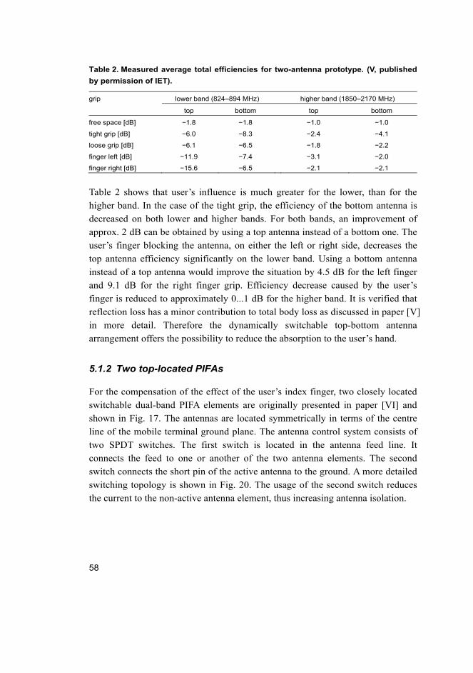
58
Table 2. Measured average total efficiencies for two-antenna prototype. (V, published
by permission of IET).
grip lower band (824–894 MHz) higher band (1850–2170 MHz)
top bottom top bottom
free space [dB] −1.8 −1.8 −1.0 −1.0
tight grip [dB] −6.0 −8.3 −2.4 −4.1
loose grip [dB] −6.1 −6.5 −1.8 −2.2
finger left [dB] −11.9 −7.4 −3.1 −2.0
finger right [dB] −15.6 −6.5 −2.1 −2.1
Table 2 shows that user’s influence is much greater for the lower, than for the
higher band. In the case of the tight grip, the efficiency of the bottom antenna is
decreased on both lower and higher bands. For both bands, an improvement of
approx. 2 dB can be obtained by using a top antenna instead of a bottom one. The
user’s finger blocking the antenna, on either the left or right side, decreases the
top antenna efficiency significantly on the lower band. Using a bottom antenna
instead of a top antenna would improve the situation by 4.5 dB for the left finger
and 9.1 dB for the right finger grip. Efficiency decrease caused by the user’s
finger is reduced to approximately 0...1 dB for the higher band. It is verified that
reflection loss has a minor contribution to total body loss as discussed in paper [V]
in more detail. Therefore the dynamically switchable top-bottom antenna
arrangement offers the possibility to reduce the absorption to the user’s hand.
5.1.2 Two top-located PIFAs
For the compensation of the effect of the user’s index finger, two closely located
switchable dual-band PIFA elements are originally presented in paper [VI] and
shown in Fig. 17. The antennas are located symmetrically in terms of the centre
line of the mobile terminal ground plane. The antenna control system consists of
two SPDT switches. The first switch is located in the antenna feed line. It
connects the feed to one or another of the two antenna elements. The second
switch connects the short pin of the active antenna to the ground. A more detailed
switching topology is shown in Fig. 20. The usage of the second switch reduces
the current to the non-active antenna element, thus increasing antenna isolation.

59
Fig. 17. Antenna structure and the dimensions. (VI, published by permission of
© [2010] IEEE).
User effect compensation
The measured total efficiency and an example of user effect compensation at the
low (825–960 MHz) and high band (1850–2170 MHz) are shown in Fig. 18. The
black curve denotes free space total efficiency of the switchable antenna when the
right element is active. Phantom hand measurements proved that placing the
index finger is on the left element when it is active, total efficiency is decreased
several decibels (dark grey curve). On average, body losses of 4.1 dB at low band
and of 2.1 dB at high band were measured. When the antenna feed is switched to
the right element and the index finger is on left element (light grey curve), the
total efficiency of the antenna structure increases 2.4 dB at the low band and
1.8 dB at the high band at maximum.
Thus, the proposed switchable dual-antenna arrangement is capable to
decrease body loss of 1.3 dB at both low and high bands, on average. The
maximum body loss compensation is 2.5 dB for the lower and 1.8 dB for the
higher frequency band, as shown in Fig. 18. It is emphasized that achieved body
loss compensation includes the losses of the switching system, since the prototype
included commercial RF switches [79]. For a more comprehensive user effect
compensation evaluation, the measured radiation efficiencies for the
corresponding cases are shown in Table 3.

60
Fig. 18. Measured total efficiency and user effect compensation when the index finger
is on top of left element. (VI, published by permission of © [2010] IEEE).
Switch loss
At the lower band the measured radiation efficiency of the reference antenna
without the hand phantom is −2.1 dB on average. Measured radiation efficiency
of the switchable antenna without the hand is −2.9 dB. At the higher band, the
radiation efficiency of the reference antenna is −1.0 dB. The corresponding value
of the switchable antenna without the phantom hand is −2.2 dB.
These indicate not only losses in the antenna structure but also 0.8–1.2 dB
insertion loss caused by the switching components. A typical insertion loss value
of the switch used is 0.3–0.4 dB in the 50 Ω line at the used frequency range. The
difference between measured and given nominal loss value can be explained by
the location of the second switch subject to high currents from the element to the
ground. Also, it has been previously found that impedance mismatch between the
transmission line and switch increases the insertion loss [94]. It is also stated [61]
that the switch location in the shorting pin of PIFA should be avoided because of
the current maximum. Losses are proportional to the square of the current through
the switch.
-12
-10
-8
-6
-4
-2
0
825 890 955 1850 1915 1980 2045 2110 2170
Tot
al e
ffic
ien
cy [
dB
]
Frequency [MHz]
no hand, feed right feed right feed left

61
Table 3. Measured total and radiation efficiencies with the index finger on the left
element.
case lower band (824–960 MHz) higher band (1850–2170 MHz)
total efficiency radiation efficiency total efficiency radiation efficiency
reference, feed right [dB] −3.5 −2.1 −1.9 −1.0
no hand, feed right [dB] −4.3 −2.9 −3.1 −2.2
feed right [dB] −7.1 −6.2 −3.9 −3.1
feed left [dB] −8.4 −7.7 −5.2 −4.0
5.1.3 Two top-located monopoles
Two switchable and top-located monopoles are evaluated in paper [VII] similarly
to the previously presented switchable PIFA arrangement. The dual-band
operation of monopoles is achieved by a meandering antenna element as shown in
Fig. 19. The effect of the non-active antenna termination was studied in terms of
the S11-parameter and total efficiency. The open termination was selected as the
most useful in this particular study. The selected termination corresponds to the
OFF state of the reflective type of a SPDT RF switch.
Fig. 19. Dimensions of the dual-monopole antenna structure and location of the
coaxial feed cable. (VII, published by permission of © [2011] IEEE).
The measured average total efficiency and body loss for both left and right
antenna elements with different phantom hand grips are shown in Table 4. High
body losses from −5.7…−5.9 dB were measured at the lower band when the index

62
finger was located on the active antenna element. In the case of the finger being
on the non-active antenna, the corresponding body losses were 2.8…3.1 dB. Thus,
the average body loss compensation of 2.8…2.9 dB can be achieved by using the
least-loaded antenna element.
At the higher band, user influence is much lower, resulting in 1.4…1.8 dB
body loss in the case of the finger being on the active antenna. Very low body loss
is measured for the finger on non-active antenna cases, only 0.7…0.8 dB. Thus,
the attainable body loss compensation is in the range of 0.6…1.1 dB.
Compared with the other user effect studies [42], [49] and [72], the results
with highly loaded antennas are at the same level.
Table 4. Average total efficiency and body loss for two monopole arrangement.
lower band (824–960 MHz) higher band (1850–2170 MHz)
total efficiency body loss total efficiency body loss
feed right feed left feed right feed left feed right feed left feed right feed left
free space [dB] −3.8 −3.9 – – −2.2 −2.7 – –
finger on active
element [dB] −9.7 −9.6 5.9 5.7 −3.6 −4.6 1.4 1.8
finger on non-
active element
[dB]
−6.9 −6.7 3.1 2.8 −3.0 −3.7 0.8 0.7
Absorption to the user hand and particularly to the user’s index finger located on
top of the antenna is high [8]. In contrast to compensation systems that decrease
user-induced impedance mismatch loss [9], it is proved that also absorption loss
caused by the mobile terminal user can be reduced in certain situations. The
measurement results showed that with the antenna arrangement used, an average
body loss reduction of 2.9 dB in the lower band and 1.1 dB in the higher band can
be achieved with the defined hand grips. Based on the results in paper [VII] this
author concludes that the proposed dynamically switchable antenna arrangement
increases antenna performance by decreasing mainly radiation absorbed to the
user’s index finger.
5.2 Discussion
The switchable antennas and space diversity are good options to decrease user-
influenced body loss and especially to reduce the absorption loss. The developed
switchable antenna technology is demonstrated with the different antenna

63
configurations and with two different antenna types. By using ideal lossless RF
switches, a performance improvement up to 9 dB is achieved compared with a
non-switchable conventional antenna structure.
In addition to the absorption loss reduction, the switchable antenna can
reduce the user-induced reflection loss. The reason for this is the use of the least-
loaded antenna element, thus providing a greater distance between the user hand
and element. Thus, by using the switchable antenna structures the distinct
switchable antenna impedance matching circuitries [78] are unnecessary.
In order to achieve the best performance of switchable antenna structure, it is
essential to minimize all losses. No advantage of the switchable antenna system is
reached if the losses of circuitry are higher than the compensated human effect. In
the case of top-located monopoles, one SPDT switch is used in a 50 Ω micro strip
line, as shown in Fig. 20. In the top-located PIFA arrangement, also shown in Fig.
20, the first switch is located in 50 Ω micro strip line and its insertion loss is
supposed to be low.
Fig. 20. Switching topologies for top-located monopole (left), for PIFA (centre)
arrangements and for top-bottom PIFA (right).
The second switch is located in the shorting line of the antenna, where the
impedance is typically low, but not possible to exactly determine. It is clear that
the loss of the second switch dominates the total loss [61], [94]. Therefore the
switch placement in the shorting position of PIFA antenna is not the best solution.
Another switching topology was used with the top-bottom antenna arrangement,
shown in Fig. 20 (right). The feeds of both antennas were connected either to the
50 Ω feed lines or to the ground. Thus, the switch location in the shorting pin of

64
the PIFA is avoided that results in the lower switch losses and the higher total
efficiency.
After publishing paper [VI], the same compensation method has been used to
decrease the effect of the user index finger [95]. The benefit gained from two
switchable coupling elements is from 2 to 6 dB in the GSM1800 frequency band
that is equal or slightly higher than the results presented in paper [VI].

65
6 Summary of publications
[I] Frequency reconfigurable micro strip-fed annular slot antenna
An annular slot antenna was used as a platform for the research of the switchable
feed structure. By changing the electrical length of the capacitive feed over the
slot, the coupling to the antenna structure was modified. The feed length was
changed by using a DC controlled PIN diode switch. Thus, two inherent
resonance modes of the antenna were excited. Regardless of the insulating DC
capacitor and switch, measured total efficiencies were 69% and 73%. Total
efficiency degradation due to the reconfiguring system was 25% of the units at
maximum compared with the reference antennas. The attained frequency shift
was 43% of the amount that naturally results from the different resonance modes.
The presented antenna type was not suitable for mobile terminal usage but the
controlling method can be applied to conventional mobile terminal antennas.
[II] Frequency-tuneable DVB-H antenna for mobile terminals
In this paper, a frequency tuneable RX antenna for DVB-H was presented. The
frequency tuning system consists of a vertical side-mounted IFA with variable
capacitor loading at the open end of the antenna element. For the first time, the
antenna location in the vertical long side edge of a 40mm × 100mm ground plane
enabled the conventional cellular system antenna design for the terminal. Because
of the low received power, a variable capacitor having a relatively small power
handling capacity could be used. The achieved relative frequency tuning was
from 470 MHz to 702 MHz with an 8 MHz instantaneous bandwidth and
reasonable gain.
[III] Frequency reconfigurable planar inverted-f antennas for portable
wireless devices
This paper presents two frequency tuning methods for PIFA, the first with
switchable tuning stubs and the second with an electronically reconfigurable
antenna element. The author was the designer of the second controlling method.
Semiconductor switches were integrated into the antenna element and the
switches were biased through the antenna feed and shorting pins, thus enabling a

66
simplified antenna tuning method. Insight into RF switch DC controlling by using
an antenna feed and shorting pins combined with DC voltage separation with a
low loss capacitor in the antenna element made the design possible. The
performance of the antennas was reasonably good, both antennas having a total
efficiency between 61% and 78%, including the losses of the controlling circuitry
and RF PIN diodes. The demonstrated maximum resonance shifts were 15–20%
of the centre frequency, but they can be controlled by changing the effective
resonator lengths.
[IV] Experimental study of hand and head effects on mobile phone antenna radiation properties
In this paper the effect of the human body on a triple-resonance PIFA-type
antenna was experimentally evaluated. The impedance reflection loss and
absorption loss caused by the phantom head and hand with six different hand
grips were measured and analysed. It was concluded that distinct hand grips
generated significant variation in the amount of loss in both the browsing and
calling modes. In the calling mode the average absorption losses in the lower
(880–990 MHz) and upper (1710–1990 MHz) frequency bands were 3.9–7.9 dB
and 1.4–9.5 dB, respectively. The corresponding losses in the browsing situation
were 1.1–4.8 dB and 0–6.7 dB. It was also concluded that the impedance
mismatch caused by the body’s effect had a minor contribution to total loss.
[V] Compensating the influence of human hand with two switchable
antennas
This paper aimed to clarify whether a two-antenna solution could reduce user
influence, compared to a single antenna solution. The two-antenna solution
included placing switchable PIFAs both at the top and the bottom of a mobile
terminal. User hand-induced performance change was measured with a near-field
antenna measurement system, using a commercial hand phantom to model four
different hand grips. This study showed that both reflection and absorption losses
can be reduced by using multiple switchable antennas instead of a single antenna
solution. Especially absorption losses were significantly reduced. When using a
two-antenna arrangement, 2…8 dB improvement in total efficiency was obtained
for the lower band, and 1.7…2.5 dB for the higher band.

67
[VI] Control system for compensation of antenna mistuning and absorption caused by user’s index finger
In this paper, an antenna arrangement and a control system that decreased the
losses caused by the user of the mobile terminal was presented. Performance of
the system is evaluated with the presence of the user hand and index finger.
Experimental results prove that two switchable antenna elements are able to
increase the total efficiency up to 2.5 dB at 900 MHz. The control system
decreases the absorption loss of the index finger up to 2 dB at frequency range
from 825 MHz to 960 MHz. At the frequency range from 1850 MHz to 2170
MHz, the compensated reflection and absorption loss is nearly the same as the
additional loss caused by the control circuitry. The measured average loss of two
switches is 1.1 dB at both the low and high band. The highest measured loss is 1.8
dB. A typical insertion loss value of one switch is 0.3–0.4 dB in the 50 Ω line at
the used frequency range. The impedance environment of the switch has a
significant role in the overall performance.
[VII] Absorption loss reduction in a mobile terminal with switchable monopole antennas
A method for compensating part of the user effect on a mobile terminal antenna
was experimentally evaluated. A dynamic selection between two separately
located antennas was used to reduce absorption caused by the user’s index finger.
The method was examined in the 900 MHz and 1900 MHz bands with dual-band
monopole antennas. The performance of the method was evaluated in terms of
antenna total efficiency, body loss, mismatch loss, and absorption loss. It was
found that a 2.9 dB reduction in average body loss is achieved in the low band if
the feed is switched to the unloaded antenna instead of the loaded one. The
corresponding reduction in the higher band is 1.1 dB.

68

69
7 Conclusions
The first part of this thesis presents three possible frequency reconfiguring
methods for resonance-type antennas, two of them directly applicable for mobile
terminal antenna frequency controlling. The antenna frequency
bandwidth-enhancing techniques for both internal cellular [III] and broadcasting
receiver antennas [II] are developed. Examined frequencies for cellular antennas
cover GSM850, GSM900, GSM1800, GSM1900 and WCDMA frequency bands.
The frequency tuneable receiving broadcast antenna is intended for the DVB-H
band covering frequencies from 470 MHz to 698 MHz.
The annular slot antenna originally presented in [I] demonstrates the
developed switchable feed structure having a capability to excite two different
resonance modes in a single unchanged slot antenna depending on the length of
the feed line. The use of a PIN diode switch with appropriate DC control circuitry
necessitated a high-efficient frequency reconfiguring for low power solutions. In
the method, where the fundamental resonance modes of an antenna are excited,
the frequency shift is largely determined by the antenna shape. Now the obtained
frequency shift was 43% for the two lowest resonance modes. The essential
merits of the antenna in question are high efficiency and DC biasing of the switch,
the disadvantage is the unsuitability of the antenna type for mobile terminals.
Low reception power, wide system frequency bandwidth, narrow
instantaneous bandwidth and small antenna volume are the requirements for the
receiving antenna satisfied by the frequency tuneable Inverted-F Antenna (IFA)
developed in this thesis. It is shown that the resonance type of antenna loaded
with a voltage-controlled variable capacitor [II] is applicable to a continuous
frequency shift to a high frequency range. Thus, the narrow resonance bandwidth
of 4% is virtually extended up to 40% bandwidth having a relative frequency shift
of 32% compared with the highest resonance frequency. The developed internal
antenna solution is vertically located on the long side edge of the terminal ground
plane.
High efficiency and novel DC biasing are the merits of the second frequency
reconfigurable Planar Inverted-F Antenna (PIFA) [III]. The antenna frequency
controlling components are positioned in the antenna element with no separate
DC biasing that disturbs antenna performance. A ground shorted antenna, feed
and short pins form the DC current loop that is used for DC biasing. The correct
placement of the RF switch and the use of appropriate capacitors to separate RF
and DC propagation paths are required in this arrangement. Attainable frequency

70
shift range mainly depends on the current path lengths of the antenna element. In
this case, the frequency shifts of 20% and 15% for the lower and higher bands of
the dual-band antenna are achieved. It is shown that the losses of the developed
system are relatively low, being in the order of measurement uncertainty in this
case. The main factor affecting reconfiguring system efficiency is the insertion
loss of the switch used. Also, the linearity and power handling capacity of the
switch are limiting factors when considering cellular-type antennas with signal
transmission and reception required.
The second part of the thesis discusses the user effect on mobile terminal
antennas and its compensation. At first, user hand and head effect is examined by
using commercial hand and head phantoms [IV]. Evaluation with the latest
user-effect studies shows relatively good correspondence, thus having a strong
background to compensation method development. User effect on mobile
terminal antennas is expressed by equations in this thesis, explaining both the
effect of the reflected and absorbed power on the antenna performance. It is
concluded that majority of the user body loss is a consequence of absorption to
the user hand and head. The user-influenced reflection loss plays a minor role in
total body loss.
All the user effect compensation methods presented in this thesis are based on
the antenna space diversity technique [V], [VI] and [VII]. Diversity is obtained by
using two switchable antennas located in separate parts of the mobile terminal
ground plane. Instead of a single antenna that is located in one part of the ground,
the use of two switchable antennas yields higher performance. This happens if the
least-loaded antenna is always used. This assumption is now validated and
verified by experimental work.
Two distinct two-antenna configurations for the user effect reduction were
developed. The first switchable antenna [V] focuses on the performance
evaluation of top or bottom antenna configurations relative to different user hand
grips. Results showed a remarkable variation in total efficiency for different grips.
With a tight grip, an improvement of approximately 2 dB can be obtained by
using a top antenna instead of a bottom one. With the highly loaded top antenna,
the use of the bottom antenna instead of the top one improves the total efficiency
up to 9 dB in the lower band. It is also concluded that the verified switchable
antenna arrangement is mainly able to compensate for absorption to the user.
The second switchable antenna structure with two side by side-located PIFA
antennas is realized by using RF switches, originally presented in paper [VI]. The
antenna locations at the top part of the terminal did not especially necessitate high

71
user effect compensation figures. As intended for the compensation of the user’s
index finger effect, the maximum body loss compensation was 2.5 dB and 1.8 dB
for the lower and higher bands, respectively. It is noteworthy that the results are
measured with functional switching circuitry that decreases the total antenna
efficiency by 0.8–1.2 dB for both bands on average. Comparison with the
nominal insertion loss value of one switch, that is in the order of 0.3–0.4 dB,
shows an additional source of loss in the verified structure. However, it is proved
that the losses of switching circuitry are much smaller than the gained benefit in
the form of increased antenna performance. The losses of the switching circuitry
can be minimized by using low loss RF switches and higher contribution to
switching circuitry design.
The antenna locations of the third switchable antenna structure, [VII], is
identical to paper [VI] but realized with monopole antennas. The main
achievement is the body loss compensation of 2.9 dB and 1.8 dB for the lower
and higher bands, respectively. In comparison with the similar PIFA arrangement,
almost identical compensation numbers are achieved. This is mainly due to the
same phantom hand grips and the equal size of the terminal ground plane.
The performance comparison with other active body loss compensation
arrangements is difficult to make because of the missing point of comparison.
This is due to the novelty of the research field of active body loss compensation.
The implications of this thesis include a better understanding of mobile
terminal antenna bandwidth enhancement and compensating body losses caused
by the user. In practise, the implementation of the presented user effect
compensation methods into commercial terminals would have significant
implications for mobile terminal users or for mobile operators, or medium
implications for both. Once losses are smaller, power requirements are reduced,
resulting in smaller batteries, longer lifetimes or more reliable connections far
from base stations. On the other hand, mobile operators can use the saved RF
power to increase the cell sizes, improve the signal to noise ratio or decrease the
base station RF power consumption.
Terminal designers can combine the results of this thesis with the knowledge
of how users hold mobile terminals when optimising antenna solutions.
Recommended future research could include deeper analysis of the influence
of the human head & hand in MIMO (multiple input – multiple output) systems,
including radio channels. Also, the comparison between the developed
compensation method, MIMO antenna arrangement and simultaneously-fed

72
antennas for user effect compensation would be an interesting topic for future
research.

73
References
1. 3rd Generation Partnership Project; Technical Specification Group GSM/EDGE Radio Access Network; Radio transmission and reception, 3GPP TS 45.005 V8.8.0.
2. 3rd Generation Partnership Project; Technical Specification Group Radio Access Network; User Equipment (UE) radio transmission and reception (TDD), 3GPP TS 25.102 V10.3.0.
3. Aberle JT, Chu M, & Birtcher CR (1992) Scattering and radiation properties of varactor-tuned microstrip antennas. Proc IEEE Antennas and Propagation Society International Symposium. Chicago, USA 4: 2229−2232.
4. Aberle JT, Sung-Hoon Oh, Auckland DT & Rogers SD (2003) Reconfigurable antennas for wireless devices. IEEE Antennas and Propagation Magazine 45(6): 148− 154.
5. Balanis CA (1997) Antenna Theory. John Wiley & Sons. 6. Balzano Q, Irwin J & Steel R (1975) Investigation of the impedance variation and
radiation loss in portable radios. Proc International Antennas and Propagation Society Symposium. 89−92.
7. Behdad N & Sarabandi K (2006) Dual-band reconfigurable antenna with a very wide tunability range. IEEE Transactions on Antennas and Propagation. 54(2): 409−416.
8. Bezooijen A van, Jongh MA de, Chanlo C, Ruijs L, Straten F van, Mahmoudi R & Roermund A van (2008) A GSM/EDGE/WCDMA adaptive series-LC matching network using RF-MEMS switches. IEEE Journal of Solid-State Circuits 43: 2259−2268.
9. Boyle KR (2003) The performance of GSM 900 antennas in the presence of people and phantoms. Proc. International Conference on Antennas and Propagation, Exeter, UK: 35−38
10. Boyle KR, Yuan Y & Ligthart LP (2007) Analysis of Mobile Phone Antenna Impedance Variations With User Proximity, IEEE Transactions on Antennas and Propagation 55(2): 364−372.
11. Chen ZN (2007) Antennas for Portable Devices. John Wiley & Sons. 12. Chu LJ (1948) Physical limitations of omni-directional antennas. Journal of Applied
Physics 19: 1163−1175. 13. Ciais P, Staraj R, Kossiavas G & Luxey C (2004) Design of an internal quad-band
antenna for mobile phones. IEEE Microwave and Wireless Components Letters. 14(4): 148−150.
14. Derneryd A, Friden J, Persson P & Stjernman A (2009) Performance of closely spaced multiple antennas for terminal applications. Proc European Conference on Antennas and Propagation. Berlin, Germany: 1612−1616.
15. Digital Video Broadcasting (DVB); DVB-H Implementation Guidelines, ETSI: TR 102 377 V1.2.1.
16. Fano RM (1950) Theoretical limitations on the broad-band matching of arbitrary impedances. J. Franklin Inst. 249: 57–83.

74
17. Firrao EL, Annema A-J & Nauta B (2008) An automatic antenna tuning system using only RF signal amplitudes. IEEE Transactions on Circuits and Systems II: Express Briefs 55: 833−837.
18. Fujimoto K (2008) Mobile Antenna Systems Handbook. Norwood, MA, Artech House.
19. GaAs Hyperabrupt Varactor Diodes MGV Series Data sheet, Metelics. http://www.aeroflex.com/ams/Metelics/pdfiles/MGV_Series_Hyperabrupt_A17041.pdf [Cited 1.11.2011]
20. Gabriel C (2007) Tissue Equivalent Material for Hand Phantoms. Physics in Medicine and Biology 52: 4205−4210.
21. Hansen RC (1981) Fundamental limitations in antennas. Proc. IEEE 69(2): 170−182. 22. Harrysson F, Medbo J, Molisch A, Johansson A & Tufvesson F (2010) Efficient
experimental evaluation of a MIMO handset with user influence. IEEE Transactions on Wireless Communications 9(2): 853−863.
23. Holopainen J, Kivekäs O, Ilvonen J, Valkonen R, Icheln C & Vainikainen P (2011) Effect of the User's Hands on the Operation of Lower UHF-Band Mobile Terminal Antennas: Focus on Digital Television Receiver. IEEE Transactions on Electromagnetic Compatibility 53(3): 831−841.
24. Holopainen J, Villanen J, Kyrö M, Icheln C & Vainikainen P (2006) Antenna for Handheld DVB Terminal. Proc IEEE International Workshop on Antenna Technology, Small Antennas and Novel Metamaterials. New York, USA: 305−308.
25. Huang L & Russer P (2008) Electrically Tunable Antenna Design Procedure for Mobile Applications. IEEE Transactions on Microwave Theory and Techniques 56(12): 2789−2797.
26. Huang L, Schroeder WL & Russer P (2005) Theoretical and experimental investigation of adaptive antenna impedance matching for multiband mobile phone applications. Proc Wideband and Multi-band Antennas and Arrays. Birmingham, UK: 13−17.
27. Huang T & Boyle KR (2007) User Interaction Studies on Handset Antennas. Proc European Conference on Antennas and Propagation. Edinburgh, UK: 1−6.
28. IEEE Std 145-1993. (1993) IEEE Standard Definitions of Terms for Antennas. 29. IEEE Xplore Digital Library, http://ieeexplore.ieee.org 30. Jensen MA & Rahmat-Samii Y (1994) The electromagnetic interaction between
biological tissue and antennas on a transceiver handset. Proc International Antennas and Propagation Society Symposium. Seattle, USA: 367−370.
31. Jung J-M, Kim S-J, Kong K-H, Lee J-S & Lee B (2007) Designing ground plane to reduce hand effects on mobile handsets. Proc IEEE Antennas and Propagation Society International Symposium. Honolulu, USA: 1040−1043.
32. Kaajakari V, Alastalo A, Jaakkola K & Seppa H (2007) Variable Antenna Load for Transmitter Efficiency Improvement. IEEE Transactions on Microwave Theory and Techniques 55(8): 1666−1672.

75
33. Karmakar NC (2005) Biasing considerations of a parasitic planar inverted-F antenna. Proc IEEE Antennas and Propagation Society International Symposium. Washington, USA 4B: 60−63.
34. Karmakar NC (2004) Shorting strap tunable stacked patch PIFA. IEEE Transactions on Antennas and Propagation 52(11): 2877−2884.
35. Karmakar NC, Hendro P & Firmansyah LS (2003) Shorting strap tunable single feed dual-band PIFA. IEEE Microwave and Wireless Components Letters 13(1): 13−15.
36. King H & Wong J (1977) Effects of a human body on a dipole antenna at 450 and 900 MHz. IEEE Transactions on Antennas and Propagation 25(3): 376−379.
37. Kivekäs O, Ollikainen J, Lehtiniemi T & Vainikainen P (2004) Bandwidth, SAR, and efficiency of internal mobile phone antennas. IEEE Transactions on Electromagnetic Compatibility. 46(1): 71−86.
38. Komulainen M & Jantunen H (2008) Switching a dual-band planar inverted-F antenna to operate in eight frequency bands. Proc. Loughborough Antennas and Propagation Conference. Loughborough, UK: 85−88.
39. Komulainen M (2009) Bandwidth enhanced antennas for mobile terminals and multilayer ceramic packages. DSc thesis. Univ. of Oulu, Dept. Electrical and Information engineering.
40. Komulainen M, Berg M, Jantunen H & Salonen E (2007) Compact varactor-tuned meander line monopole antenna for DVB-H signal reception. Electronics Letters 43(24): 1324−1326.
41. Komulainen M, Berg M, Jantunen H, Salonen E & Free C (2008) A Frequency Tuning Method for a Planar Inverted-F Antenna. IEEE Transactions on Antennas and Propagation 56(4): 944−950.
42. Krogerus J, Toivanen J, Icheln C & Vainikainen P (2007) Effect of the Human Body on Total Radiated Power and the 3-D Radiation Pattern of Mobile Handsets. IEEE Transactions on Instrumentation and Measurements 56: 2375−2385.
43. Krupka Z (1968) The effect of the human body on radiation properties of small-sized communication systems. IEEE Transactions on Antennas and Propagation 16(2): 154−163.
44. Laheurte J-M (2001) Switchable CPW-fed slot antenna for multifrequency operation. Electronics Letters 37(25): 1498−1500.
45. Li C-H, Ofli E, Chavannes N & Kuster N (2009) Effects of Hand Phantom on Mobile Phone Antenna Performance. IEEE Transactions on Antennas and Propagation 57(9): 2763−2770.
46. Lim J-H, Back G-T, Ko Y-I, Song C-W & Yun T-Y (2010) A Reconfigurable PIFA Using a Switchable PIN-Diode and a Fine-Tuning Varactor for USPCS/WCDMA/m-WiMAX/WLAN. IEEE Transactions on Antennas and Propagation 58(7): 2404−2411.
47. Lindberg P & Kaikkonen A (2006) Earpiece Cord Antenna for DVB-H Reception in Wireless Terminals. Electronics Letters 42(11): 609−611.
48. Lindberg P (2008) Antennas for Mobile Wireless Communication. In Yarman BS (ed) Design of Ultra Wideband Antenna Matching Networks. Springer: 43.

76
49. Lindberg P, Kaikkonen A & Kochali B (2008) Body Loss Measurements of Internal Terminal Antennas in Talk Position using Real Human Operator. Proc International Workshop on Antenna Technology Chiba, Japan: 358−261.
50. Lindberg P & Ojefors E (2006) A bandwidth enhancement technique for mobile handset antennas using wavetraps. IEEE Transactions on Antennas and Propagation 54(8): 2226−2233.
51. Zi Dong Liu, Hall PS & Wake D (1997) Dual-frequency planar inverted-F antenna. IEEE Transactions on Antennas and Propagation 45(10): 1451−1458.
52. Lu D (2008) A mobile antenna study of radiation efficiency in human head and hand environment. Proc IEEE AP-S International Symposium. San Diego, USA: 1−4.
53. McLean JS (1996) A re-examination of the fundamental limits on the radiation Q of electrically small antennas. IEEE Transactions on Antennas and Propagation 44(5): 672−676.
54. Mak ACK, Rowell CR, Murch RD & Mak C-L (2007) Reconfigurable Multiband Antenna Designs for Wireless Communication Devices. IEEE Transactions on Antennas and Propagation 55(7): 1919−1928.
55. Manteuffel D (2004) A concept to minimize the user interaction of mobile phones. Proc IEE Technical Seminar on Antenna Measurement and SAR. Loughborough, UK: 1−4.
56. Milosavljevic Z (2004) Adjustable Planar Antenna, US patent US2004041733. 57. Mingo de J, Valdovinos A, Crespo A, Navarro D & Garcia P (2004) An RF
electronically controlled impedance tuning network design and its application to an antenna input impedance automatic matching system. IEEE Transactions on Microwave Theory and Techniques 52(2): 489−497.
58. Myllymaki S, Huttunen A, Palukuru VK, Jantunen H, Berg M & Salonen E (2010) Capacitive recognition of the user`s hand grip position in mobile handsets. Progress In Electromagnetics Research B 22: 203−220.
59. Nielsen JO, Pedersen GF, Olesen K & Kovacs IZ (2001) Statistics of measured body loss for mobile phones. IEEE Transactions on Antennas and Propagation 49(9): 1351−1353.
60. Okoniewski M & Stuchly MA (1996) A study of the handset antenna and human body interaction. IEEE Transactions on Microwave Theory and Techniques 44(10): 1855−1864.
61. Ollikainen J (2004) Design and implementation techniques of wideband mobile communication antennas. DSc thesis. Helsinki University of Technology, Dept. Electrical and Communications engineering.
62. Ollikainen J, Kivekas O & Vainikainen P (2002) Low-loss tuning circuits for frequency-tunable small resonant antennas. Proc IEEE International Symposium on Personal, Indoor and Mobile Radio Communications. Lisbon, Portugal: 1882−1887.
63. Ollikainen J, Fischer M & Vainikainen P (1999) Thin dual-resonant stacked shorted patch antenna for mobile communications. Electronics Letters 35(6): 437−438.
64. Panayi PK, Al-Nuaimi MO & Ivrissimtzis IP (2001) Tuning techniques for planar inverted-F antenna. Electronics Letters 37(16): 1003−1004.

77
65. Jae-Hyoung Park, Yong-Dae Kim, Yong-Hee Park, Hee-Chul Lee, Hyouk Kwon, Hyo-Jin Nam & Jong-Uk Bu (2007) Tunable planar inverted-F antenna using rf MEMS switch for the reduction of human hand effect. Proc IEEE 20th International Conference on Micro Electro Mechanical Systems. Hyogo, Japan: 163−166.
66. Papapolymerou J, Lange KL, Goldsmith CL, Malczewski A & Kleber J (2003) Reconfigurable double-stub tuners using MEMS switches for intelligent RF front-ends. IEEE Transactions on Microwave Theory and Techniques 51(1): 271−278.
67. Patent database, Esp@cenet http://fi.espacenet.com/ 68. Pedersen GF, Nielsen JO, Olesen K & Kovacs IZ (1998) Measured variation in
performance of handheld antennas for a large number of test persons. Proc 48th IEEE Vehicular Technology Conference. Ottawa, Canada: 505−509.
69. Pedersen GF, Olesen K & Larsen SL (1999) Bodyloss for handheld phones. Proc Vehicular Technology Conference. Houston, USA: 1580−1584.
70. Pelosi M, Franek O, Knudsen MB, Christensen M & Pedersen GF (2009) A Grip Study for Talk and Data Modes in Mobile Phones. IEEE Transactions on Antennas and Propagation 57(4): 856−865.
71. Pelosi M, Franek O, Knudsen MB & Pedersen GF (2009) Influence of dielectric loading on PIFA antennas in close proximity to user's body. IET Electronics Letters 5: 246−247.
72. Pelosi M, Franek O, Knudsen MB, Pedersen GF & Andersen JB (2010) Antenna Proximity Effects for Talk and Data Modes in Mobile Phones. IEEE Antennas and Propagation Magazine 52(3): 15−27.
73. Peroulis D, Sarabandi K & Katehi LPB (2005) Design of reconfigurable slot antennas. IEEE Transactions on Antennas and Propagation 53(2): 645−654.
74. Plicanic V, Buon Kiong Lau, Derneryd A & Zhinong Ying (2009) Actual Diversity Performance of a multiband diversity antenna with hand and head effects. IEEE Transactions on Antennas and Propagation 57(5): 1547−1556.
75. Pozar DM (1998) Microwave engineering, 2nd ed. John Wiley & Sons 76. Pues HF & Van de Capelle AR (1989) An impedance-matching technique for
increasing the bandwidth of microstrip antennas. IEEE Transactions on Antennas and Propagation 37(11): 1345−1354.
77. Rahola J & Vainikainen P (2006) Optimal antenna placement for mobile terminals using characteristic mode analysis. Proc European Conference on Antennas and Propagation. Nice, France: 1−6.
78. Ramachandran P, Milosavljevic ZD & Beckman C (2009) Adaptive matching circuitry for compensation of finger effect on handset antennas. Proc European Conference on Antennas and Propagation. Berlin, Germany: 801−804.
79. RF1200 data sheet, RFMD, Greensboro, USA. 80. Samuelsson VP, Buon Kiong L, Derneryd A & Ying Z (2009) Channel capacity
performance of multi-band dual antenna in proximity of a user. Proc International Workshop on Antenna Technology. Santa Monica, USA: 1−4.

78
81. Sanad H (1994) Effect of the shorting posts on short circuit microstrip antennas. Proc Antennas and Propagation Society International Symposium. Seattle, USA 2: 794−797.
82. Sanchez-Hernandez DA (2009) High frequency electromagnetic dosimetry. Artech House
83. Sanchez-Perez C, De Mingo J, Garcia-Ducar P & Carro PL (2009) Performance improvement of mobile DVB-H terminals using a reconfigurable impedance tuning network. IEEE Transactions on Consumer Electronics 55: 1875−1882.
84. Sankey L & Popovic Z (2009) Adaptive tuning for handheld transmitters. Proc IEEE International Microwave Symposium. Boston, USA: 225−228.
85. Satimo website. (2008) [Online]. Available: http://www.satimo.com 86. Shepherd NH & Chaney WG (1958) Personal radio antennas. IRE Transactions on
Vehicular Communications 10(1): 23−31. 87. Sjoblom P & Sjoland H (2005) An adaptive impedance tuning CMOS circuit for ISM
2.4-GHz band. IEEE Transactions on Circuits and Systems I 52(6): 1115−1124. 88. Sjoblom P & Sjoland H (2007) Characterization of a CMOS impedance tuning unit
for DVB-H. Analog Integrated Circuits and Signal Processing 52(3): 79–87. 89. The 3rd Generation Partnership Project (3GPP), ‘Technical Specification 45.008’,
v9.4.0, 2010. 90. Thornell-Pers A & Erlandsson P (2007) Compact Active Multiband Cellular Antenna
for Mobile Handsets. Proc International Workshop on Antenna Technology: Small and Smart Antennas Metamaterials and Applications. Cambridge, UK: 81-84.
91. Toftgard J, Hornsleth SN & Andersen JB (1993) Effects on portable antennas of the presence of a person. IEEE Transactions on Antennas and Propagation 41(6): 739−746.
92. Vainikainen P, Ollikainen J, Kivekäs O & Kelander I (2002) Resonator-based analysis of the combination of mobile handset antenna and chassis. IEEE Transactions on Antennas and Propagation 50: 1433−1444.
93. Valkonen R, Holopainen J, Icheln C & Vainikainen P (2007) Broadband Tuning of Mobile Terminal Antennas. Proc European Conference on Antennas and Propagation. Edinburgh, UK: 1−6.
94. Valkonen R, Holopainen J, Icheln C & Vainikainen P (2008) Minimization of power loss and distortion in a tuning circuit for a mobile terminal antenna. Proc 13th International Symposium on Antennas and Propagation. Taipei, Taiwan: 449−452.
95. Valkonen R, Myllymäki S, Huttunen A, Holopainen J, Ilvonen J, Vainikainen P & Jantunen H (2010) Compensation of finger effect on a mobile terminal antenna by antenna selection. Proc International Conference on Electromagnetics in Advanced Applications. Sydney, Australia: 364−367
96. Villanen J & Vainikainen P (2007) The design of optimum impedance matching networks for coupling element based antenna structures. Proc IEEE Antennas and Propagation Society International Symposium. Honolulu, USA: 3672−3675.

79
97. Virga KL & Rahmat-Samii Y (1995) An enhanced-bandwidth integrated dual L antenna for mobile communications systems-design and measurement. Proc. IEEE Antennas and Propagation Society International Symposium. Newport Beach, USA 2: 1120−1123.
98. Virga KL & Rahmat-Samii Y (1997) Low-profile enhanced-bandwidth PIFA antennas for wireless communications packaging. IEEE Transactions on Microwave Theory and Techniques 45(10): 1879−1888.
99. Waterhouse RB, Targonski SD & Kokotoff DM (1998) Design and performance of small printed antennas. IEEE Transactions on Antennas and Propagation 46(11): 1629−1633.
100. Whatley RB, Zhen Zhou & Melde KL (2006) Reconfigurable RF impedance tuner for match control in broadband wireless devices. IEEE Transactions on Antennas and Propagation 54(2): 470−478.
101. Wheeler HA (1947) Fundamental Limitations of Small Antennas. Proc IRE. 35(12): 1479-1484.
102. Witt FJ (1989) Optimum lossy matching networks for resonant antennas. Proc Antennas and Propagation Society International Symposium. San Jose, USA: 1360-1363.
103. Kin-Lu Wong & Kai-Ping Yang (1998) Modified planar inverted F antenna. Electronics Letters 34(1): 7−8.
104. Wong K-L (2003) Planar Antennas for Wireless Communications. John Wiley & Sons. 105. Wong K-L, Chi YW, Chen B & Yang S (2006) Internal DTV Antenna for Folder-
Type Mobile Phone. Microwave and Optical Technology Letters 48(6): 1015−1019. 106. Wook YJ (2007) Method and apparatus for switching antenna according to user’s grip
style. Korean Patent KR20070114611. 107. Yaghjian, AD & Best SR (2005) Impedance, bandwidth, and Q of antennas. IEEE
Transactions on Antennas and Propagation 53(4): 1298−1324. 108. Yarman BS (Ed) (2008) Design of Ultra Wideband Antenna Matching Networks.
Springer. 109. Ying Z (2005) Television Antenna for a Portable Communication Device. Patent
WO2005081361. 110. Zervos T, Peppas K, Lazarakis F, Alexandridis AA, Dangakis K & Soras C (2007)
Channel capacity evaluation for a multiple-input-multiple-output terminal in the presence of user's hand. IET Microwaves, Antennas & Propagation 1(6): 1137−1144.

80

81
Original publications
I Berg M, Komulainen M, Salonen E & Jantunen H (2006) Frequency reconfigurable microstrip-fed annular slot antenna. Proc European Conference on Antennas and Propagation. Nice, France: 1−6.
II Berg M, Komulainen M, Palukuru V, Jantunen H & Salonen E (2007) Frequency-tunable DVB-H antenna for mobile terminals. Proc IEEE Antennas and Propagation International Symposium. Honolulu, USA: 1072−1075.
III Komulainen M, Berg M. Mähönen J. Jantunen H & Salonen E. (2006) Frequency reconfigurable planar inverted-F antennas for portable wireless devices. Proc European Conference on Antennas and Propagation. Nice, France: 1−6.
IV Berg M, Sonkki M & Salonen E (2009) Experimental study of hand and head effects to mobile phone antenna radiation properties. Proc European Conference on Antennas and Propagation. Berlin, Germany: 437−440.
V Berg M & Salonen E (2011) Compensating the influence of human hand with two switchable antennas. IET Microwaves, Antennas & Propagation: In press
VI Berg M & Salonen E (2010) Control system for compensation of antenna mistuning and absorption caused by user’s index finger. Proc European Conference on Antennas and Propagation. Barcelona, Spain: 1−5.
VII Berg M, Sonkki M & Salonen E (2011) Absorption loss reduction in a mobile terminal with switchable monopole antennas. IEEE Transactions on Antennas and Propagation. 59(11): 4379−4383.
Reprinted with permission from ESA (I and III), IEEE (II, IV, VI and VII) and
IET (V).
Original publications are not included in the electronic version of the dissertation.

82
A C T A U N I V E R S I T A T I S O U L U E N S I S
Book orders:Granum: Virtual book storehttp://granum.uta.fi/granum/
S E R I E S C T E C H N I C A
393. Khatri, Narendar Kumar (2011) Optimisation of recombinant protein productionin Pichia pastoris : Single-chain antibody fragment model protein
394. Paavola, Marko (2011) An efficient entropy estimation approach
395. Khan, Zaheer (2011) Coordination and adaptation techniques for efficientresource utilization in cognitive radio networks
396. Koskela, Timo (2011) Community-centric mobile peer-to-peer services:performance evaluation and user studies
397. Karsikas, Mari (2011) New methods for vectorcardiographic signal processing
398. Teirikangas, Merja (2011) Advanced 0–3 ceramic polymer composites for highfrequency applications
399. Zhou, Jiehan (2011) Pervasive service computing: community coordinatedmultimedia, context awareness, and service composition
400. Goratti, Leonardo (2011) Design, analysis and simulations of medium accesscontrol protocols for high and low data rate applications
401. Huttunen, Sami (2011) Methods and systems for vision-based proactiveapplications
402. Weeraddana, Pradeep Chathuranga (2011) Optimization techniques for radioresource management in wireless communication networks
403. Räsänen, Teemu (2011) Intelligent information services in environmentalapplications
404. Janhunen, Janne (2011) Programmable MIMO detectors
405. Skoglind-Öhman, Ingegerd (2011) Participatory methods and empowerment forhealth and safety work : Case studies in Norrbotten, Sweden
406. Kellokumpu, Vili-Petteri (2011) Vision-based human motion description andrecognition
407. Rahko, Matti (2011) A qualification tool for component package feasibility ininfrastructure products
408. Rajala, Hanna-Kaisa (2011) Enhancing innovative activities and tools for themanufacturing industry: illustrative and participative trials within work systemcases
C410etukansi.kesken..fm Page 2 Tuesday, November 8, 2011 10:39 AM

ABCDEFG
UNIVERS ITY OF OULU P.O.B . 7500 F I -90014 UNIVERS ITY OF OULU F INLAND
A C T A U N I V E R S I T A T I S O U L U E N S I S
S E R I E S E D I T O R S
SCIENTIAE RERUM NATURALIUM
HUMANIORA
TECHNICA
MEDICA
SCIENTIAE RERUM SOCIALIUM
SCRIPTA ACADEMICA
OECONOMICA
EDITOR IN CHIEF
PUBLICATIONS EDITOR
Senior Assistant Jorma Arhippainen
Lecturer Santeri Palviainen
Professor Hannu Heusala
Professor Olli Vuolteenaho
Senior Researcher Eila Estola
Director Sinikka Eskelinen
Professor Jari Juga
Professor Olli Vuolteenaho
Publications Editor Kirsti Nurkkala
ISBN 978-951-42-9690-1 (Paperback)ISBN 978-951-42-9691-8 (PDF)ISSN 0355-3213 (Print)ISSN 1796-2226 (Online)
U N I V E R S I TAT I S O U L U E N S I SACTAC
TECHNICA
U N I V E R S I TAT I S O U L U E N S I SACTAC
TECHNICA
OULU 2011
C 410
Markus Berg
METHODS FOR ANTENNA FREQUENCY CONTROL AND USER EFFECT COMPENSATION IN MOBILE TERMINALS
UNIVERSITY OF OULU,FACULTY OF TECHNOLOGY, DEPARTMENT OF COMMUNICATIONS ENGINEERING;CENTRE FOR WIRELESS COMMUNICATIONS;INFOTECH OULU
C 410
ACTA
Markus B
ergC410etukansi.kesken..fm Page 1 Tuesday, November 8, 2011 10:39 AM