method statement shotcrete application directly onto sheet ... · (temporary) shotcrete lining for...
TRANSCRIPT
METHOD STATEMENT Shotcrete application directly onto sheet waterproofing membranes MARCH 2015 / VERSION 1 / SIKA SERVICES AG / MARKUS JAHN, PHILIPPE STOLL
FOR LOCAL TRANSLATION
METHOD STATEMENT Language/Region/Translation template
SHOTCRETE ONTO MEMBRANES FOR LOCAL TRANSLATION
MARCH 2015, Version 1
Document ID
2/24
TABLE OF CONTENTS 1 Introduction 3
1.1 General designs for mined tunnels 3 1.2 Options for secondary lining 3
2 Primary lining 5
2.1 Shotcrete lining 5 2.2 Preliminary waterproofing 5
3 Waterproofing system 6
3.1 General 6 3.2 Levelling layer 6 3.3 Cushion layer 7 3.4 Synthetic sheet waterproofing membrane 8 3.5 Protective sheet (optional) 8 3.6 Additional items 9 3.7 Contact grouting measures 9
4 Rebound reduction systems 10
4.1 General remarks 10 4.2 Option 1: Steel mesh 10
4.2.1 Synthetic anchor system 10
4.2.2 Trumpet flange system 12
4.2.3 Screw nut system 13
4.2.4 Self-standing / self-supporting reinforcement 13
4.2.5 Contra disc system 14
4.3 Option 2: membranes with a textured/profiled surace 15 4.4 Option 3: Combined system 15
5 Sprayed secondary lining 16
5.1 General rules for shotcrete lining 16 5.2 Shotcrete quality 16 5.3 Spraying technique 17 5.4 Application steps for shotcrete lining 17 5.5 Curing 18 5.6 Option with fiber reinforced concrete 19
6 Hybrid secondary lining systems 19
7 Project References 20
7.1 Lungern bypass, Switzerland 20 7.2 Bypass Vespucio El Salto-Kennedy, Chile 21 7.3 Brandleitetunnel, Germany 22 7.4 Fernthaltunnel, Germany 22 7.5 Step Tunnel, Abu Dhabi 23 7.6 Ebbs Tunnel, Austria 23 7.7 Additional references 23
8 Literature 24
24

METHOD STATEMENT Language/Region/Translation template
SHOTCRETE ONTO MEMBRANES FOR LOCAL TRANSLATION
MARCH 2015, Version 1
Document ID
3/24
1 INTRODUCTION
1.1 GENERAL DESIGNS FOR MINED TUNNELS
Standard mined tunnels consist of either one or two shells depending on the ambient conditions and the requirements regarding durability and water tightness:
1. Single shell tunnels made of one shotcrete or precast segmental lining which are not covered in this Method Statement.
2. Double shell tunnels used for high durability and water-tightness requirements, which consist of a primary (temporary) shotcrete lining for rock support, a waterproofing system and a permanent secondary lining made of in-situ concrete that is also fully protected by the waterproofing system, see Figure 1.
Figure 1: Standard build-up for double-shell tunnels composed of shotcrete (i.e. primary lining), waterproofing system and in-situ concrete (i.e. secondary lining)
1.2 OPTIONS FOR SECONDARY LINING
It is common practice for the secondary linings in double-shell tunnels to use in-situ concrete. This is cast-in-place by large movable formwork assemblies on rails, which are usually between 10m and 12.5m long. This approach provides a fast and economical solution for the regular cross sections of long tunnels. However, there are technical and commercial limitations:
In short tunnels, tailor-made formwork assemblies might not be cost effective.
For changing diameters, widening sections, cross-passages etc., the formwork has to be modified or even completely replaced.
METHOD STATEMENT Language/Region/Translation template
SHOTCRETE ONTO MEMBRANES FOR LOCAL TRANSLATION
MARCH 2015, Version 1
Document ID
4/24
In these instances, a secondary lining made of shotcrete instead of in-situ concrete can provide the following advantages:
Lower complexity of the construction operations
The possibility of saving time and money because of there being no need for costly formwork
When fibers can also be added to the shotcrete, there can be additional cost savings because of reduced reinforcement requirements and operations
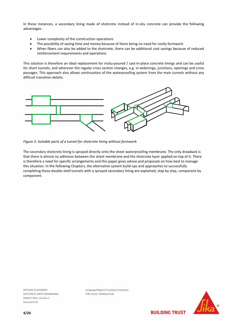
This solution is therefore an ideal replacement for insitu-poured / cast-in-place concrete linings and can be useful for short tunnels, and wherever the regular cross section changes, e.g. in widenings, junctions, openings and cross passages. This approach also allows continuation of the waterproofing system from the main tunnels without any difficult transition details.
Figure 2: Suitable parts of a tunnel for shotcrete lining without formwork
The secondary shotcrete lining is sprayed directly onto the sheet waterproofing membrane. The only drawback is
that there is almost no adhesion between the sheet membrane and the shotcrete layer applied on top of it. There
is therefore a need for specific arrangements and this paper gives advice and proposals on how best to manage
this situation. In the following Chapters, the alternative system build-ups and approaches to successfully
completing these double-shell tunnels with a sprayed secondary lining are explained, step by step, component by
component.
METHOD STATEMENT Language/Region/Translation template
SHOTCRETE ONTO MEMBRANES FOR LOCAL TRANSLATION
MARCH 2015, Version 1
Document ID
5/24
2 PRIMARY LINING
2.1 SHOTCRETE LINING
The primary lining usually consists of shotcrete that is applied onto the natural substrate immediately after the
excavating process; this is done in variable thicknesses and supported by anchors, lattice girders etc., depending
on the prevailing ground conditions and site requirements.
2.2 PRELIMINARY WATERPROOFING
The preliminary waterproofing measures are needed to control and channel any water ingress at an early stage, therefore providing more or less dry working conditions for both the main contractor and the specialist contractor for the waterproofing system.
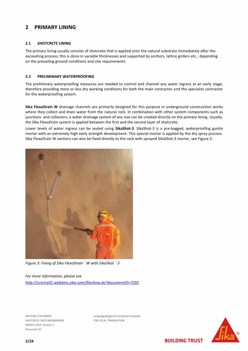
Sika FlexoDrain W drainage channels are primarily designed for this purpose in underground construction works where they collect and drain water from the natural rock. In combination with other system components such as junctions and collectors, a water drainage system of any size can be created directly on the primary lining. Usually, the Sika FlexoDrain system is applied between the first and the second layer of shotcrete.
Lower levels of water ingress can be sealed using SikaShot-3. SikaShot-3 is a pre-bagged, waterproofing gunite mortar with an extremely high early strength development. This special mortar is applied by the dry spray process. Sika FlexoDrain W sections can also be fixed directly to the rock with sprayed SikaShot-3 mortar, see Figure 3.
Figure 3: Fixing of Sika FlexoDrain® W with SikaShot®-3
For more information, please see
http://ccintra01.webdms.sika.com/fileshow.do?documentID=7292
METHOD STATEMENT Language/Region/Translation template
SHOTCRETE ONTO MEMBRANES FOR LOCAL TRANSLATION
MARCH 2015, Version 1
Document ID
6/24
3 WATERPROOFING SYSTEM
3.1 GENERAL
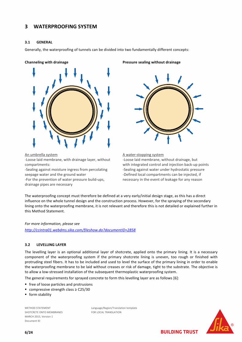
Generally, the waterproofing of tunnels can be divided into two fundamentally different concepts:
Channeling with drainage Pressure sealing without drainage
An umbrella system -Loose laid membrane, with drainage layer, without compartments: -Sealing against moisture ingress from percolating seepage water and the ground water -For the prevention of water pressure build-ups, drainage pipes are necessary
A water-stopping system -Loose laid membrane, without drainage, but with integrated control and injection back-up points -Sealing against water under hydrostatic pressure -Defined local compartments can be injected, if necessary in the event of leakage for any reason
The waterproofing concept must therefore be defined at a very early/initial design stage, as this has a direct
influence on the whole tunnel design and the construction process. However, for the spraying of the secondary
lining onto the waterproofing membrane, it is not relevant and therefore this is not detailed or explained further in
this Method Statement.
For more information, please see
http://ccintra01.webdms.sika.com/fileshow.do?documentID=2858
3.2 LEVELLING LAYER
The levelling layer is an optional additional layer of shotcrete, applied onto the primary lining. It is a necessary component of the waterproofing system if the primary shotcrete lining is uneven, too rough or finished with protruding steel fibers. It has to be included and used to level the surface of the primary lining in order to enable the waterproofing membrane to be laid without creases or risk of damage, tight to the substrate. The objective is to allow a low-stressed installation of the subsequent thermoplastic waterproofing system.
The general requirements for sprayed concrete to form this levelling layer are as follows [6]:
free of loose particles and protrusions
compressive strength class ≥ C25/30
form stability

METHOD STATEMENT Language/Region/Translation template
SHOTCRETE ONTO MEMBRANES FOR LOCAL TRANSLATION
MARCH 2015, Version 1
Document ID
7/24
Maximum aggregate size 8 mm
Ideally aggregates should be rounded, if not there is a need to double crush them to make them less angular.
The layer thickness must be ≥ 50 mm
Steel bars or sections must be covered by minimum 50 mm shotcrete
Evenness BA: BT= min. 10:1, see Figure 4
Figure 4: Dimensions of the substrate evenness
Figure 5: Rock anchor detail
3.3 CUSHION LAYER
Between the levelling layer and the actual waterproofing membrane, an additional protection/drainage layer must be installed, depending on the waterproofing concept:
Channeling with drainage Pressure sealing without drainage
Suitable cushion/drainage layer options -Drainage mesh, e.g. Sikaplan® W Tundrain -Dimpled sheet, e.g. Sika® Drain -Geocomposite -Polypropylene monofilament / in a random network
Suitable cushion layer -Polypropylene geotextile min. 500 g/m
2
e.g. Sikaplan® W Felt PP

METHOD STATEMENT Language/Region/Translation template
SHOTCRETE ONTO MEMBRANES FOR LOCAL TRANSLATION
MARCH 2015, Version 1
Document ID
8/24
The cushion/drainage layer is usually fixed to the levelling layer with shot-fired nails (e.g. Hilti nails) with Sikaplan® Discs, which are also then used as the fixing points for the following membrane layer, as shown in Figure 6. Therefore, these fixing discs must also be made of the same base material as the intended waterproofing membrane, i.e. PVC or TPO.
Figure 6: Detail of Sikaplan® W Tundrain (black perforated surface), with Sikaplan® WP Disc 80/10mm yellow (yellow round discs) and membrane layer (black and yellow)
3.4 SYNTHETIC SHEET WATERPROOFING MEMBRANE
Synthetic sheet membranes are placed and installed to completely cover the cushion/drainage layer, in order to provide the waterproof layer in the waterproofing system. The two main types of membrane materials used are:
Sikaplan® WP based on PVC (PolyVinylChloride) Sikaplan® WT based on FPO (Flexible PolyOlefin) These Sikaplan® membranes must be minimum 2.0mm thick. The membranes are spot fixed to the levelling layer on the Sikaplan discs. According to German ZTV-ING Standards, the minimum number of fixing points per m
2 is 1 for the invert, 2 for the benches and 3 for the arches. In over-
spray areas, an additional 2-3 pcs/m2 are required to guarantee a close fit, tight to the substrate, and to reduce
any membrane flutter (movement).
3.5 PROTECTIVE SHEET (OPTIONAL)
An additional protective layer is designed to protect the synthetic polymer waterproofing membranes from mechanical damage during installation of the reinforcement and casting of the concrete. For waterproofing in structures where the secondary lining is not reinforced, protective layers are not normally necessary, except around the stop-end formwork. But in certain countries, if additional reinforcement is specified, the waterproofing membrane must always be protected by an additional protective layer [2, 3]. The use of Sikaplan ®WP Protection Sheet on top of PVC membranes and Sikaplan ®WT Protection Sheet on top of TPO membranes provides protection that is very resistant to external influences and protects the waterproofing membranes from damage caused by installation of the steel reinforcement, and during application of the sprayed concrete etc. These protective sheets are fixed by spot welding directly to the waterproofing membranes [4, 5].
METHOD STATEMENT Language/Region/Translation template
SHOTCRETE ONTO MEMBRANES FOR LOCAL TRANSLATION
MARCH 2015, Version 1
Document ID
9/24
3.6 ADDITIONAL ITEMS
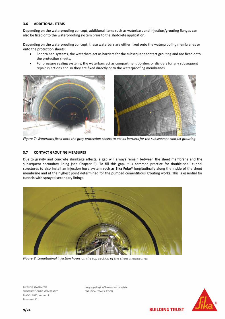
Depending on the waterproofing concept, additional items such as waterbars and injection/grouting flanges can also be fixed onto the waterproofing system prior to the shotcrete application. Depending on the waterproofing concept, these waterbars are either fixed onto the waterproofing membranes or onto the protection sheets:
For drained systems, the waterbars act as barriers for the subsequent contact grouting and are fixed onto the protection sheets.
For pressure sealing systems, the waterbars act as compartment borders or dividers for any subsequent repair injections and so they are fixed directly onto the waterproofing membranes.
Figure 7: Waterbars fixed onto the grey protection sheets to act as barriers for the subsequent contact grouting
3.7 CONTACT GROUTING MEASURES
Due to gravity and concrete shrinkage effects, a gap will always remain between the sheet membrane and the subsequent secondary lining (see Chapter 5). To fill this gap, it is common practice for double-shell tunnel structures to also install an injection hose system such as Sika Fuko® longitudinally along the inside of the sheet membrane and at the highest point determined for the pumped cementitious grouting works. This is essential for tunnels with sprayed secondary linings.
Figure 8: Longitudinal injection hoses on the top section of the sheet membranes
METHOD STATEMENT Language/Region/Translation template
SHOTCRETE ONTO MEMBRANES FOR LOCAL TRANSLATION
MARCH 2015, Version 1
Document ID
10/24
4 REBOUND REDUCTION SYSTEMS
4.1 GENERAL REMARKS
Shotcrete does not adhere to smooth synthetic sheet membranes; therefore it is necessary to implement a rebound reduction system, which helps to decrease the amount of wasted material. Wet shotcrete with a high binder content sticks to the membranes up to a certain layer thickness and this phenomenon is clearly related to the shotcrete’s weight (density ca. 2.4 tons/m
3) and age. Shotcrete requires the addition of an accelerating
admixture (e.g. Sika Sigunit) in order to shorten the setting time. However, accelerators also attract water and can make the shotcrete matrix drier, in which case the adhesion forces decrease, causing a debonding process from the synthetic membrane to develop due to gravitation.
These issues can result in very high rebound rates (> 30%), also significantly reducing the efficiency of the underground construction process. Therefore a rebound reduction arrangement must be established and the most commonly used systems include:
4.2 OPTION 1: STEEL MESH
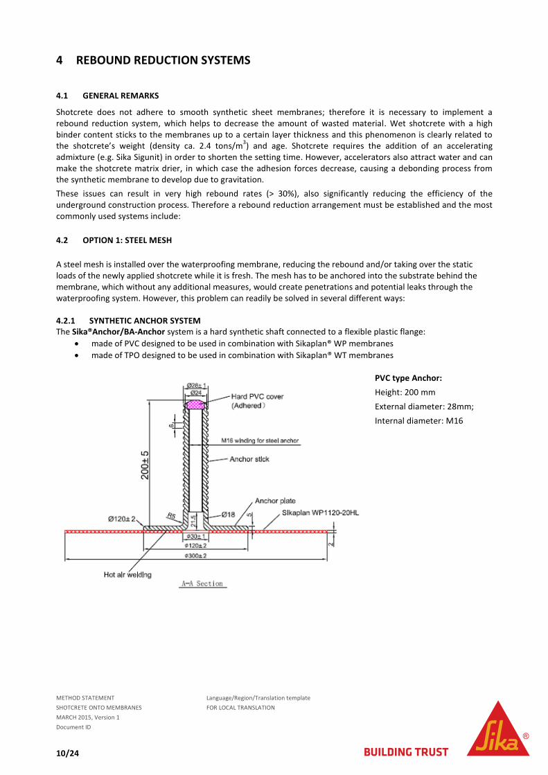
A steel mesh is installed over the waterproofing membrane, reducing the rebound and/or taking over the static loads of the newly applied shotcrete while it is fresh. The mesh has to be anchored into the substrate behind the membrane, which without any additional measures, would create penetrations and potential leaks through the waterproofing system. However, this problem can readily be solved in several different ways: 4.2.1 SYNTHETIC ANCHOR SYSTEM The Sika®Anchor/BA-Anchor system is a hard synthetic shaft connected to a flexible plastic flange:
made of PVC designed to be used in combination with Sikaplan® WP membranes
made of TPO designed to be used in combination with Sikaplan® WT membranes
PVC type Anchor:
Height: 200 mm
External diameter: 28mm;
Internal diameter: M16

METHOD STATEMENT Language/Region/Translation template
SHOTCRETE ONTO MEMBRANES FOR LOCAL TRANSLATION
MARCH 2015, Version 1
Document ID
11/24
PVC type flange:
External diameter: 300 mm
Thickness 2.0 mm
The synthetic anchor is used to fix the rebound reduction mesh through the waterproofing membrane layer. The steps required to install the system are as follows:
Cut a hole into the waterproofing system Drill a hole into the primary lining Clean the drilled hole by high pressure water jet to remove any dust Remove any residual water with compressed air. There must be no free water in the hole before injection Inject 1/3 to 1/2 of the hole depth with Sika AnchorFix or use anchor capsules Carefully set the synthetic anchor within the hardening time of Sika AnchorFix or the anchor capsule, until the
hard flange is pressed firmly onto the membrane (avoiding air entrapment). Clean the area to be welded, free from dust, oil, grease, etc. Watertight heat weld the anchor flange to the sheet waterproofing membrane. Insert the steel anchor into the anchor shaft Install the thin steel mesh close to the membrane layer surface. Fix the spider clamps
Figure 9: Detailed graph of the different parts of the Sika Anchor system, in case of Sikaplan® WP
1. D32 mm Hole
2. Sika AnchorFix
3. Hard PVC Shell
4. Anchor Steel
5. Reinforcement Rebars
6. Concrete Shell
7. Sikaplan PVC Membrane
8. Hard PVC Flange
9. Welding
10. Fixing Nuts
11. Anchor Spider clamp
12. Distance Holder
13. Reinforced Mesh
14. Shotcrete
15. Fixing Disk
METHOD STATEMENT Language/Region/Translation template
SHOTCRETE ONTO MEMBRANES FOR LOCAL TRANSLATION
MARCH 2015, Version 1
Document ID
12/24
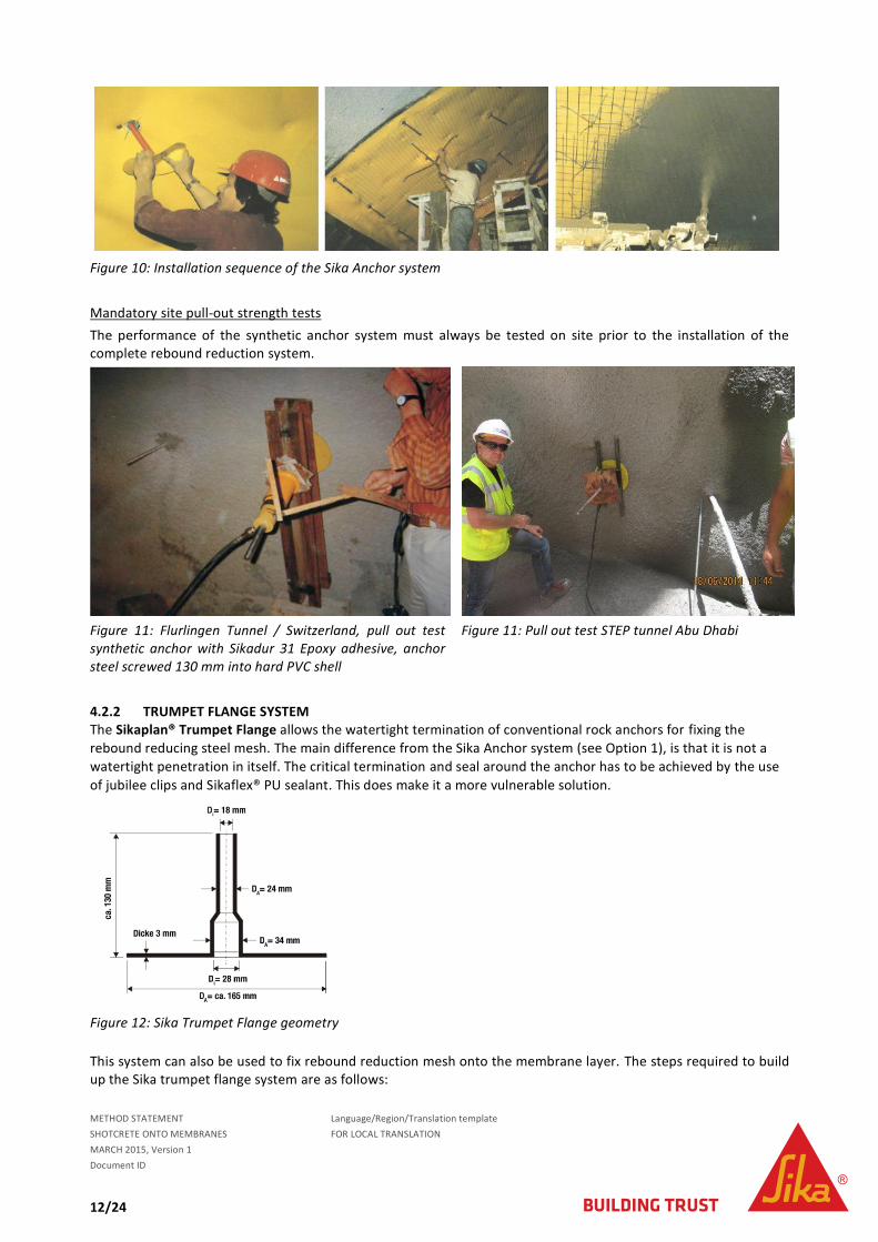
Figure 10: Installation sequence of the Sika Anchor system
Mandatory site pull-out strength tests
The performance of the synthetic anchor system must always be tested on site prior to the installation of the complete rebound reduction system.
Figure 11: Flurlingen Tunnel / Switzerland, pull out test synthetic anchor with Sikadur 31 Epoxy adhesive, anchor steel screwed 130 mm into hard PVC shell
Figure 11: Pull out test STEP tunnel Abu Dhabi
4.2.2 TRUMPET FLANGE SYSTEM The Sikaplan® Trumpet Flange allows the watertight termination of conventional rock anchors for fixing the
rebound reducing steel mesh. The main difference from the Sika Anchor system (see Option 1), is that it is not a
watertight penetration in itself. The critical termination and seal around the anchor has to be achieved by the use
of jubilee clips and Sikaflex® PU sealant. This does make it a more vulnerable solution.
Figure 12: Sika Trumpet Flange geometry
This system can also be used to fix rebound reduction mesh onto the membrane layer. The steps required to build up the Sika trumpet flange system are as follows:

METHOD STATEMENT Language/Region/Translation template
SHOTCRETE ONTO MEMBRANES FOR LOCAL TRANSLATION
MARCH 2015, Version 1
Document ID
13/24
Cut a hole into and through the waterproofing system Install conventional rock bolts Clean the area to be welded (free from any dust, oil, grease, etc) Place and watertight weld the Sika trumpet flange to the tunnel waterproofing membrane Tightly close the trumpet shaft around the rock anchor using jubilee clips and Sikaflex® PU sealant
Figure 13: Termination of the trumpet around the anchor with Jubilee clips and Sikaflex® 11FC (PU Sealant)
4.2.3 SCREW NUT SYSTEM This is the same as the trumpet flanged system, but with a screw-nut instead. See Chapter 7.2 for more details.
4.2.4 SELF-STANDING / SELF-SUPPORTING REINFORCEMENT In certain cases, the use of self-supporting reinforcement with lattice girders can be a suitable alternative to the options above. However, be aware that the rebound reducing mesh can never be fixed as close to the waterproofing membrane as it can with the Sika Anchor system, due to the irregularities of the excavated profile! Usually, this method is only used in combination with a textured membrane, see Option 3, Chapter 4.4.
Figure 14: Installation sequence of self-standing / self-supporting reinforcement

METHOD STATEMENT Language/Region/Translation template
SHOTCRETE ONTO MEMBRANES FOR LOCAL TRANSLATION
MARCH 2015, Version 1
Document ID
14/24
4.2.5 CONTRA DISC SYSTEM Instead of a membrane penetration, the steel mesh is fixed to the surface with a welded contra disc. The contra disc is welded to the membrane at the same locations as the fixing discs are holding the membrane in place at the back. In this way, the stress to the membrane is limited to the minimum. Nevertheless, the number of membrane fixings has to be increased and the spraying technique outlined in chapter 5 is not applicable. The shotcrete has to be applied in a radial pattern in order to achieve a self-standing shell as fast as possible.
Figure 15: Fixing Disc and Contra-Disc. The central nail fixings must always be correctly attached to the substrate
Figure 16: Chicken wire mesh fixed with contra discs
METHOD STATEMENT Language/Region/Translation template
SHOTCRETE ONTO MEMBRANES FOR LOCAL TRANSLATION
MARCH 2015, Version 1
Document ID
15/24
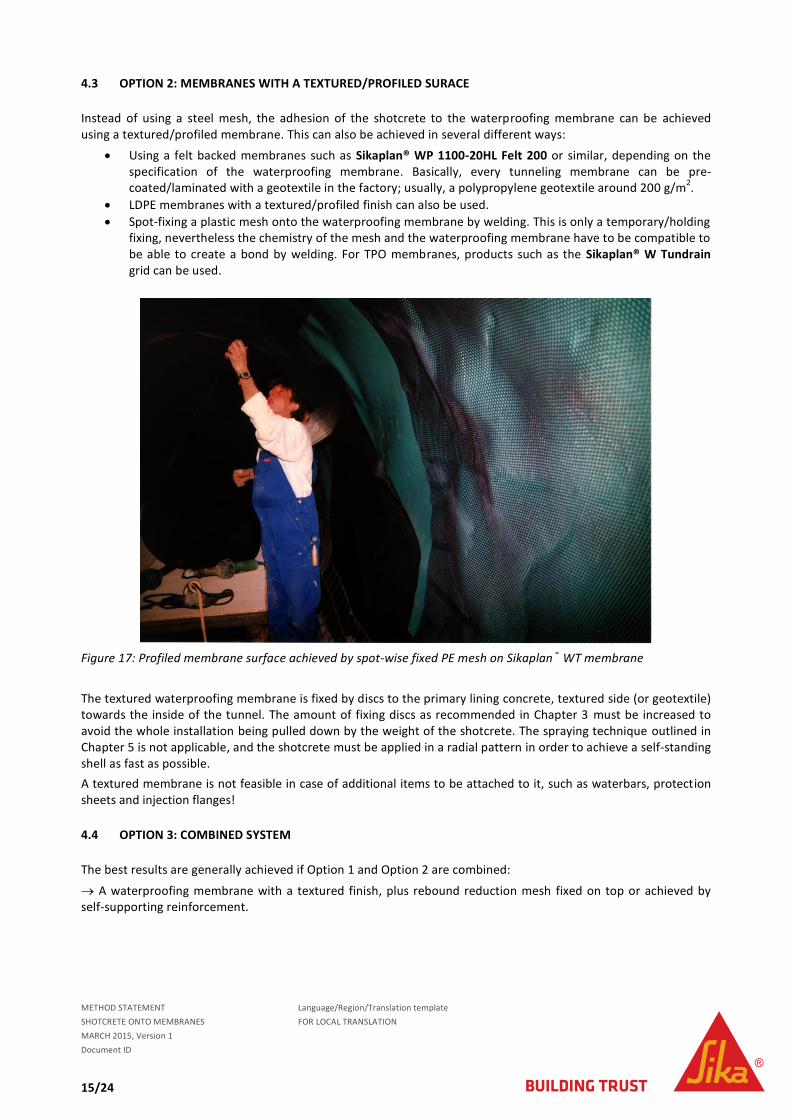
4.3 OPTION 2: MEMBRANES WITH A TEXTURED/PROFILED SURACE
Instead of using a steel mesh, the adhesion of the shotcrete to the waterproofing membrane can be achieved using a textured/profiled membrane. This can also be achieved in several different ways:
Using a felt backed membranes such as Sikaplan® WP 1100-20HL Felt 200 or similar, depending on the specification of the waterproofing membrane. Basically, every tunneling membrane can be pre-coated/laminated with a geotextile in the factory; usually, a polypropylene geotextile around 200 g/m
2.
LDPE membranes with a textured/profiled finish can also be used.
Spot-fixing a plastic mesh onto the waterproofing membrane by welding. This is only a temporary/holding fixing, nevertheless the chemistry of the mesh and the waterproofing membrane have to be compatible to be able to create a bond by welding. For TPO membranes, products such as the Sikaplan® W Tundrain grid can be used.
Figure 17: Profiled membrane surface achieved by spot-wise fixed PE mesh on Sikaplan® WT membrane
The textured waterproofing membrane is fixed by discs to the primary lining concrete, textured side (or geotextile) towards the inside of the tunnel. The amount of fixing discs as recommended in Chapter 3 must be increased to avoid the whole installation being pulled down by the weight of the shotcrete. The spraying technique outlined in Chapter 5 is not applicable, and the shotcrete must be applied in a radial pattern in order to achieve a self-standing shell as fast as possible.
A textured membrane is not feasible in case of additional items to be attached to it, such as waterbars, protection sheets and injection flanges!
4.4 OPTION 3: COMBINED SYSTEM
The best results are generally achieved if Option 1 and Option 2 are combined:
A waterproofing membrane with a textured finish, plus rebound reduction mesh fixed on top or achieved by self-supporting reinforcement.

METHOD STATEMENT Language/Region/Translation template
SHOTCRETE ONTO MEMBRANES FOR LOCAL TRANSLATION
MARCH 2015, Version 1
Document ID
16/24
5 SPRAYED SECONDARY LINING
5.1 GENERAL RULES FOR SHOTCRETE LINING
To achieve a high quality shotcrete lining several measures must be taken:
The sheet waterproofing membrane has to have a close fit to the surface to provide a smooth, preferably wrinkle-free lining with the membrane. The membrane must neither bounce nor move during the shotcrete application.
To use stiff and vibration-free reinforcement steel. To produce a shotcrete lining, which is dense and free of voids, spraying through several layers of reinforcing
must be avoided. Subsequently contact grouting the ridge gap between the waterproofing membrane and the shotcrete lining. The shotcrete lining must have the same compressive strength as the concrete lining The shotcrete must be cured correctly. To install an adequate rebound reduction system and to achieve less than 10% rebound.
5.2 SHOTCRETE QUALITY
Table 1 and Figure 18 give an overview of the requirements for the different shotcrete layers.
Table 1: final compressive strengths according to SN531 198 (Switzerland)
Figure 18: Sprayed concrete classes according to SN 531 198 (Switzerland)
METHOD STATEMENT Language/Region/Translation template
SHOTCRETE ONTO MEMBRANES FOR LOCAL TRANSLATION
MARCH 2015, Version 1
Document ID
17/24
All of these requirements can be achieved with a well executed application and the mix design shown in Table 2:
Component Unit Quantity Type
Cement [kg] 420 OPC
Water/cement [] 0.48
Maximum aggregate size [mm] 8
Superplasticizer [% of cement’s
weight]
0.8-1.2 Sika ViscoCrete
Accelerator (alkali-free) [% of cement’s
weight]
6-8 Sigunit
Table 2: Formulation for all sprayed concrete classes
5.3 SPRAYING TECHNIQUE
The main targets are:
To create a dense and homogeneous matrix To achieve a good bond between the shotcrete and the reinforcing steel To produce a close, tight fit with the membrane layer To reduce the rebound level
All of these requirements can be achieved by:
ensuring the waterproofing system is correctly applied installing a securely fixed steel reinforcement structure using a suitable rebound reduction system using a suitable mix design spraying according to a defined spray pattern using a very well-experienced nozzleman
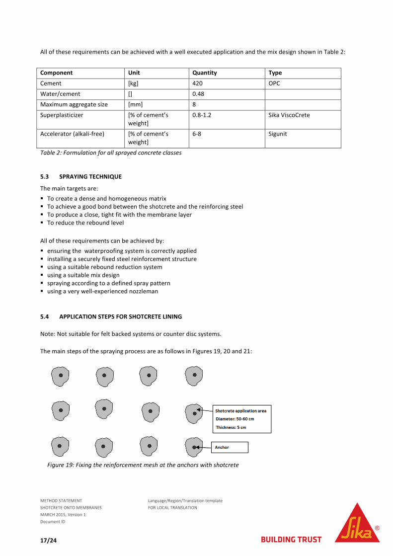
5.4 APPLICATION STEPS FOR SHOTCRETE LINING
Note: Not suitable for felt backed systems or counter disc systems.
The main steps of the spraying process are as follows in Figures 19, 20 and 21:
Figure 19: Fixing the reinforcement mesh at the anchors with shotcrete
METHOD STATEMENT Language/Region/Translation template
SHOTCRETE ONTO MEMBRANES FOR LOCAL TRANSLATION
MARCH 2015, Version 1
Document ID
18/24
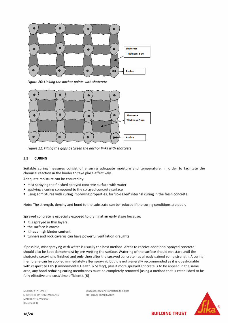
Figure 20: Linking the anchor points with shotcrete
Figure 21: Filling the gaps between the anchor links with shotcrete
5.5 CURING
Suitable curing measures consist of ensuring adequate moisture and temperature, in order to facilitate the chemical reaction in the binder to take place effectively.
Adequate moisture can be ensured by:
mist spraying the finished sprayed concrete surface with water applying a curing compound to the sprayed concrete surface using admixtures with curing improving properties, for 'so-called' internal curing in the fresh concrete.
Note: The strength, density and bond to the substrate can be reduced if the curing conditions are poor.
Sprayed concrete is especially exposed to drying at an early stage because:
it is sprayed in thin layers the surface is coarse it has a high binder content tunnels and rock caverns can have powerful ventilation draughts
If possible, mist spraying with water is usually the best method. Areas to receive additional sprayed concrete
should also be kept damp/moist by pre-wetting the surface. Watering of the surface should not start until the
shotcrete spraying is finished and only then after the sprayed concrete has already gained some strength. A curing
membrane can be applied immediately after spraying, but it is not generally recommended as it is questionable
with respect to EHS (Environmental Health & Safety), plus if more sprayed concrete is to be applied in the same
area, any bond reducing curing membranes must be completely removed (using a method that is established to be
fully effective and cost/time efficient). [6]

METHOD STATEMENT Language/Region/Translation template
SHOTCRETE ONTO MEMBRANES FOR LOCAL TRANSLATION
MARCH 2015, Version 1
Document ID
19/24
5.6 OPTION WITH FIBER REINFORCED CONCRETE
To further minimze labour intensive working procedures, fiber reinforced shotcrete can be used instead of steel
rebars. In this situation, the first 3cm of shotcrete in contact with the waterproofing membrane must be applied
without fibers as an initial protection layer. Then, steel or plastic fiber reinforced shotcrete can be sprayed to
complete the required lining thickness. This is purely an additional safety measure, as from practical experience,
fibers will not damage the membrane during the application, especially not when synthetic plastic fibers are used.
6 HYBRID SECONDARY LINING SYSTEMS
In many projects, the most economic approach for the secondary lining can be a hybrid solution:
Cast in-situ walls
Sprayed arches
The main reasons for this are that wall formwork can be placed much easier than arch formwork, plus generally, in-situ concrete is more economic than shotcrete. Furthermore in this way, the geometry of the walls in widening sections can be kept continuous, whilst the arch geometry is changing.
Figure 22: Combination of insitu concrete and shotcrete lining [1]
Additional reasons for using a hybrid secondary lining: Road tunnels generally have higher surface finish requirements than rail tunnels (i.e. for Metros and Trains). due to road traffic scattered salt in winter, which can more easily attack and penetrate tunnel walls with the higher surface roughness produced when the lining is made with shotcrete,. Also with cast in-situ concrete, the smoother crack-free surfaces reduce the quantity of pollutant build-up and penetration, whilst also allowing more efficient cleaning operations to be carried out.

METHOD STATEMENT Language/Region/Translation template
SHOTCRETE ONTO MEMBRANES FOR LOCAL TRANSLATION
MARCH 2015, Version 1
Document ID
20/24
7 PROJECT REFERENCES
7.1 LUNGERN BYPASS, SWITZERLAND
Hybrid secondary lining system for the tunnel junctions:
Cast in-situ walls
Sprayed arches with rebound reduction using thin mesh and the Sika trumpet flange system for sealing
the fixing penetrations.
Figure 23: Diagram of Lungern bypass project’s waterproofing system for the arch areas
To reduce rebound, wire mesh is installed on the anchors with a low clearance/close to the protective membrane sheet. This system is described in Chapter 4.2.2. The gap to the waterproofing membrane is about 3 times the largest aggregate size (gap from 24 to 30 mm). The application of the shotcrete is carried out in a grid. The areas around the anchors are first secured with sprayed concrete, and then these points are linked to form a grid.
This prevents the rebound mesh from “flapping” and the freshly applied sprayed concrete from getting detached. Finally the compartments formed between the grids can be filled to form a full surface layer of sprayed concrete. At the anchors the first actual reinforcement layer is then fixed to a spacer for the second layer. After over-spraying the first layer with shotcrete, the second reinforcement layer is fixed to the spacers and then this is also fully covered with sprayed concrete. Finally, the surfaces are levelled with screeding rails and float finished with trowels as required for the project.

METHOD STATEMENT Language/Region/Translation template
SHOTCRETE ONTO MEMBRANES FOR LOCAL TRANSLATION
MARCH 2015, Version 1
Document ID
21/24
Figure 24: Detail of the steps followed to spray the waterproofing system structure
Please follow this link to an article on the Lungern bypass tunnel project :
http://www.tunnel-online.info/download/446935/2012_03_Umfahrung_Lungern.pdf
7.2 BYPASS VESPUCIO EL SALTO-KENNEDY, CHILE
Rebound reduction by thin mesh and “spiders” (screw nut fixed)
In Chile the Bypass Vespucio El Salto-Kennedy was built in 2000. The waterproofing system was formed using Sikaplan PVC membranes in which penetrations were made for fixing the required rebound reduction mesh.
Trumpet flanges were placed over these fixings and they were sealed with screw nuts over the membrane to seal the connection and ensure watertightness between the membrane layer and the trumpets. After that, a wire mesh was attached to the fixings and securely held by metal 'spiders', which were also tightened onto the fixings. This system requires a minimum space of three times the diameter of the largest aggregates between the membrane layer and the wire mesh in order to sufficiently reduce the rebound and achieve the desired quality of the shotcrete lining.
Please, follow this link to details of this rebound reduction structure
http://intranet.sika.com/corp_concrete_bu_video_wet_process_shotcrete_on_sikaplan
METHOD STATEMENT Language/Region/Translation template
SHOTCRETE ONTO MEMBRANES FOR LOCAL TRANSLATION
MARCH 2015, Version 1
Document ID
22/24
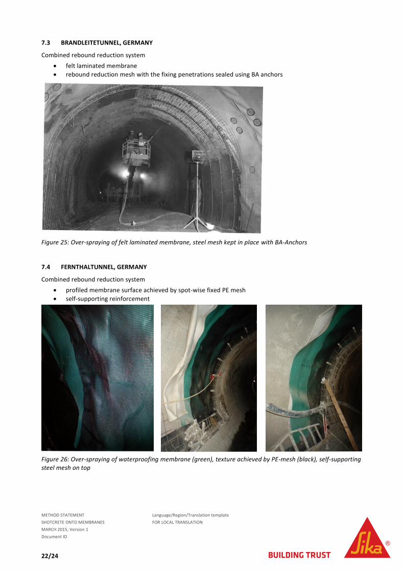
7.3 BRANDLEITETUNNEL, GERMANY
Combined rebound reduction system
felt laminated membrane
rebound reduction mesh with the fixing penetrations sealed using BA anchors
Figure 25: Over-spraying of felt laminated membrane, steel mesh kept in place with BA-Anchors
7.4 FERNTHALTUNNEL, GERMANY
Combined rebound reduction system
profiled membrane surface achieved by spot-wise fixed PE mesh
self-supporting reinforcement
Figure 26: Over-spraying of waterproofing membrane (green), texture achieved by PE-mesh (black), self-supporting
steel mesh on top
METHOD STATEMENT Language/Region/Translation template
SHOTCRETE ONTO MEMBRANES FOR LOCAL TRANSLATION
MARCH 2015, Version 1
Document ID
23/24
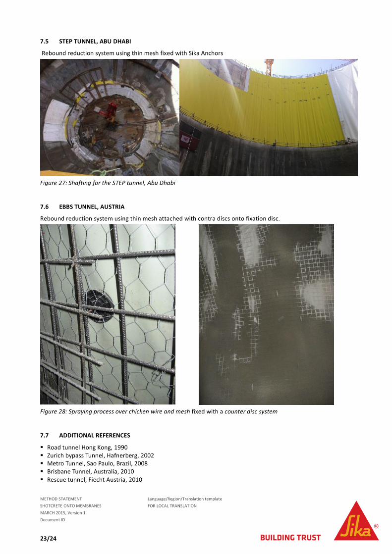
7.5 STEP TUNNEL, ABU DHABI
Rebound reduction system using thin mesh fixed with Sika Anchors
Figure 27: Shafting for the STEP tunnel, Abu Dhabi
7.6 EBBS TUNNEL, AUSTRIA
Rebound reduction system using thin mesh attached with contra discs onto fixation disc.
Figure 28: Spraying process over chicken wire and mesh fixed with a counter disc system
7.7 ADDITIONAL REFERENCES
Road tunnel Hong Kong, 1990 Zurich bypass Tunnel, Hafnerberg, 2002 Metro Tunnel, Sao Paulo, Brazil, 2008 Brisbane Tunnel, Australia, 2010 Rescue tunnel, Fiecht Austria, 2010

METHOD STATEMENT Language/Region/Translation template
SHOTCRETE ONTO MEMBRANES FOR LOCAL TRANSLATION
MARCH 2015, Version 1
Document ID
24/24
8 LITERATURE
[1]Frank Heimbecher, Wilhem Decker, Hans-Günter Faust: Einsatzbereiche endgültiger Spritzbeton-konstruktionen
im Tunnelbau, page 33. 2004
[2] SN 564 272: Abdichtung und Entwasserung von Bauten unter Terrain und im Untergrund. 2009
[3] BAST ZTV-ING: Teil 5: Tunnelbau – Abschnitt 5: Abdichtung. 2007
[4] Lemke S: Worldwide specifications for membranes and joints – state of the art. 2009
[5] Sika Schweiz AG: Flexible Waterproofing of Tunnels with Sikaplan Membranes. 2010
[6] Norwegian concrete association, Publication no. 7: Sprayed Concrete for Rock Support. Pages 94 and 95, August 2011.
SIKA COMPANY
Target Market
Address
Zip, City
Country
www-address
Version given by
First name Surname
Phone: Phone
Fax: Fax
Mail: E-mail