meter panel construction, an innovative solution for basements, subways … · 2015-04-27 · meter...
TRANSCRIPT

105
Int. J. Struct. & Civil Engg. Res. 2013 Solomon Ntow Densu and Mohammed Salifu, 2013
METER PANEL CONSTRUCTION, AN INNOVATIVESOLUTION FOR BASEMENTS, SUBWAYS AND
RIVER TRAINING WORKS
D K Kanhere1*, Dr R A Hegde2 and Dr V T Ganpule3
There is growing need of basements, subways and other underground excavations in congestedcities. Considering proximity of other structures and traffic problems open excavation may notbe always feasible. Panels of small width, forming a wall are constructed along retention periphery,adequately designed as cantilever sheet piles and anchored in substratum to achieve stabilityagainst various forces may be adopted here. The particular problem is studied; equationsdeveloped for stability considering passive pressure and balancing couple by trial and errormethod, the results are verified with analytical model (FEM). Results are presented here.
Keywords: Meter panel, sheet pile, Alternate method, Segmental, Underground excavations,basements and subways
1 STUP Consultants P Ltd., Navi Mumbai-400705.2 Sardar Patel college of Engineering, Andheri-Mumbai.3 V T Ganpule & Associates, Mumbai.
*Corresponding Author: D K Kanhere,[email protected]
INTRODUCTIONIn the last 20 years building constructionactivity in most of the major cities has been onthe rise. With effect, vacant and garden plots,sites with natural depression, ponds, etc.,which served to hold the run off in a heavydownpour are now reclaimed and occupiedby structures. Such situations coupled withblockages of old drains as well as the collapseof these drains lead to water logging problems.Moreover, the present construction practice issuch that the open spaces between the buildingand plot boundary are covered fully with paver
ISSN 2319 – 6009 www.ijscer.comVol. 2, No. 1, February 2013
© 2013 IJSCER. All Rights Reserved
Int. J. Struct. & Civil Engg. Res. 2013
Research Paper
blocks or lean concrete. As a consequence,the component of run off which could have beenabsorbed by the soil cover is appreciablyreduced. The net result of all these elementsis a large increase in magnitude of runoff onthe roads to be catered for by storm waterdrains. This leads to flooding of areas, burstingof underground storm water drains and evenat times collapse of old buildings as well asbasements, which are under construction.Such a severe water logging problem hasnecessitated widening and deepening ofnatural drains and existing system of drains.

106
Int. J. Struct. & Civil Engg. Res. 2013 Solomon Ntow Densu and Mohammed Salifu, 2013
The construction for widening and deepening
has to be carried out in the crowded neighbor-
hood and/or in close vicinity of the unauthorized
slums which pose a serious constraint on open
spaces required for deep excavations.
For all these types of constructions like car
parking, subways, widening and deepening of
drains excavating deep sections is necessary.
The methods deployed presently are either
extremely costly or cause great hinderance to
traffic and public movement.
PRESENT METHODS ADOPTEDAt present the construction of deep exca-vations is achieved by one of the methods,described briefly below. The advantages andlimitations of each method are discussed.
Conventional Open Excavation
This is the simplest mode of excavation. Butthe presence of high ground water table, nonavailability of adequate open space, andproximity of existing structures like buildingsand roads, do not permit the constructor toresort to conventional open excavation while
dealing with deep open excavationsparticularly in crowded urban areas.
At times it is possible to tackle the problem
by taking small stretches of say 3 m length ata time. Even in this scheme the problems tobe faced remain the same, but their gravitycould be somewhat less because of the size.Another serious disadvantage is the uncertaintime frame of the works due to problem of
dewatering and stability of slopes. In thismethod the excavation is made first for a smallstretch and then retaining element of the samelength is constructed. Where the time is not
critical, the method could be used subject toother conditions not posing serious problems.
Diaphragm Wall
The very widely used method for prestigiousprojects is construction of diaphragm walls asan enabling work. The diaphragm walls areeither free standing walls or anchoreddiaphragm walls. In the grab method of boringas deployed in diaphragm wall construction, itis not possible to penetrate into even ‘soft’ rockso as to derive reactive forces to deal with theactive forces generated by retained earth andas such resort to pre-stressed anchors isessential. These anchors are quite long andoften pass through the adjoining properties inorder to obtain required reactive force.Further, the inclination of the anchors not onlyincreases the length of anchors but also addsa vertical force on the cross section of the wall.In the olden days, due to the unawareness ofthe general public, this aspect was overlookedand many a buildings with basements wereconstructed. But nowadays, such activity willlead to legal complications and heavycompensation.
The other aspect of diaphragm wallconstruction is the need of specialized agencypossessing costly equipment. Due toavailability of only a limited number ofspecialist agencies, constructing diaphragmwalls becomes costlier.
The advantage of grabbing system is theconstruction of larger panels. Panel size of 5to 6 m is quite common. The longer length ofpanels necessitates higher slump of concrete,necessitating concreting using at least twotremie pipes in one panel. The operation withtwo tremie pipes calls for a watchful eye to

107
Int. J. Struct. & Civil Engg. Res. 2013 Solomon Ntow Densu and Mohammed Salifu, 2013
ensure coordination during concreting activity.The tendency to use only central tremie whileconstructing the diaphragm walls leads toextraordinary bulging of concrete. Diaphragmwalls are relatively impermeable but are notabsolutely ‘Bone Dry’. Further the grab sizesavailable in market are limited and as suchthe structural engineers have to use the sizeavailable and modify the design to meet thestructural requirement, which often adds to thecost.
In addition to the panel construction theprovision of anchors and their stressing is atime consuming and costly affair. Mid levelanchors, if required, lead to a break in theexcavation activity. The free standingdiaphragm walls necessitate chiselingoperation for develop-ment of adequate socketlength in rock. In case soft/hard rock is metabove the scheduled basement excavationlevel, advancing the panels through weatheredrock /soft rock is quite a task. It is because ofall these difficulties that use of diaphragm wallsis a costlier and time consuming proposal.
The construction of guide walls running to adepth of 0.5 m to 1 m ( with minimum of 20 cmthickness) on both faces of wall all along theperiphery of the diaphragm wall alignment forthe entire length of diaphragm wall adds totime and cost.
Touching Piles
Another quite popular method is constructionof touching/conjugate piles to serve asretaining elements. Many clients, engineersand planners opt for this method because ofeasy availability of contracting agencies.Since piling has become a very commonactivity, it is rather convenient to get an agency
at a competitive price. But the seriousdisadvantage of the method is the excessiveconsumption of steel on account of circularnature of the piles to withstand the bendingforces. Further to accommodate more steeland to ensure easy flow of concrete beyondthe reinforcement cage, the pile diameter isrequired to be increased, leading to extra costand consuming of more space and thus limitingthe usable area. Socket for piles could bemade into the rock with some difficultydepending upon the quality of the rock (ofcourse at a cost). The touching piles systemcan serve only as an enabling work andrequires the construction of regular retainingelement with suitable water proofing featuresat a later date.
Box Pushing
For last 40 years, box pushing technique has
been used with advantage for construction of
subways particularly for Railway crossings.
The technique of box pushing requires suitable
space abutting proposed subway alignment
for the construction of reaction blocks and
casting of boxes. The method requires expert
knowledge and special equipment. These
parameters make the scheme costly. The initial
preparation time for the construction of the
reaction blocks and construction of precast
boxes is quite appreciable.
The method is not suitable for subways
located in crowded areas of metropolitan
cities due to constraint of space and time and
availability of suitable stratum. For basements,
it is an extremely costly affair. As regards
widening and deepening of nallahs, box
pushing is not suitable.

108
Int. J. Struct. & Civil Engg. Res. 2013 Solomon Ntow Densu and Mohammed Salifu, 2013
METHODOLOGY OFCONSTRUCTION FOR METERPANEL SCHEMEMeter panel construction is done using theconventional piling rig (tripod), changing onlythe shapes of boring tools like bailer, chisel,bottom or guide casing. The use of conven-tional piling rigs makes the system costeffective. Depending on the time schedule, thenumber of rigs can be conveniently increased(which is a very important feature of thescheme) without much difficulty, as such rigsare easily available. The shape of theconventional circular piles is changed torectangular shape. The tolerances of the toolare carefully planned so as to ensure thedevelopment of required size of the bore. Thechisels and bailer of the required dimensioncan be easily fabricated. Another specificadvantage of the meter panel system is thatby just changing the tool size, the wall ofstructurally required width for a given retentioncan be constructed. The feature is of greatimportance in optimizing the design. Such anadvantage is not available with a diaphragmwall as the fabrication of the grabs is a verycostly affair compared to fabrication of cuttingtools of the meter panel.
Construction Procedure
Excavate manually to a depth of 0.5 m to 1 mso as to lower the casing in the excavationmade along the construction line of meterpanel and then hammer the casing for a depthof 2 m. Guide casing of two meter length issufficient to ensure verticality of the wall.
Boring can be commenced with the help ofbailer. The weight of the bailer and its cuttingshoe are the most important parameters for
faster progress. In case of sandy formation theDirect Mud Circulation (DMC) method couldbe adopted. The bore is developed by thebailer or by DMC up to the hard stratum.
On reaching weathered rock, the bore isdeveloped further with the help of speciallydesigned rectangular chisel. Normally, in caseof circular piles, chiseling is continued for halfan hour and bailing is done for 10 min. But incase of meter panels, chiseling for a period of20 min necessitates bailing due to the natureof the tool as it strikes or hits the same contactarea over and over. The rectangular shape ofthe tool prevents change of direction of blows(which is possible for circular piles) and leadsto increased quantum of chiseling efforts. Ingeneral, it is observed that the chiseling timefor a given socket length for a meter panel wallis about 40% to 50 % more than that forequivalent conventional circular piles.
On reaching the desired founding levelincluding the required socket, steel cage islowered. The cover provided is minimum 75mm to main reinforcement. It is very essentialto make the steel cage sufficiently rigid by tackwelding so that the cage does not deviate fromits contemplated position. For a wall of 6 to 7m depth, having retained height of 4 to 5 m therequired steel is of the order of 70 to 80 kg/m3
which is normal for a free standing retainingwall. On lowering the reinforcement cage,concreting is done with tremie. All precautionsrequired for tremie concreting are to bescrupulously followed to ensure denseconcrete.
The grade of concrete preferably should beM 25 and above. The water cement ratioshould be kept between 0.4 and 0.45 byadding plasticizers as required. The slump of

109
Int. J. Struct. & Civil Engg. Res. 2013 Solomon Ntow Densu and Mohammed Salifu, 2013
concrete should be around 160 mm, so as tohave a self compacting mix. Since the meterpanel length is restricted to 1 to 1.5 m, desiredconcreting can be done only by a singletremie. It reduces the pressure of moni-toringon execution agency. For meter panels inclayey soils, joints will not pose any seriousproblem of trickling of water. For sandy soils,joints will pose some problem which can betackled by sealing the joint by nailing strip ofprecast concrete or steel plate or rubber sealwith the meter panel wall similar to water stopsin diaphragm walls.
After casting the first panel, alternate panelis taken up. In this fashion the work can becompleted. Depending on the elbow spaceavailable, the number of rigs can be increasedto meet the desired time frame.
The specifications for piles as outlined inIRC 78 or IS 2911 are to be followed whileexecuting the meter panels.
APPLICATIONS OF METERPANELSMeter panel type of construction can be easilydeployed for developing deep basements evenin crowded cities. Touching meter panels havebeen effectively deployed for widening/diversion of Nalahs, natural drains, as well assubways construction. Each application ofmeter panel is dealt below:
About 200 basements, going as deep as12 to 15 m, have been constructed in the cityof Mumbai by using meter panels or touchingpiles. In the city of Chennai, just abutting MountRoad, the Indian Express Mall has a basementsection going as deep as 17 m and the plintharea is also very large (about 1,000 of sq m.)
The construction of this basement wasaccomplish by resorting to touching piles. Withjudicious use of well point system, deepexcavation to the tune of 17 m was done byconstruction of touching piles of 900 mmdiameter going to a depth of 23-25 m andadequately reinforced. Anchors were notprovided.
Deep excavation of the order of 6 m andabove in crowded metropolitan cities is a trickyaffair. The promoter and user would prefer touse as much plot area as possible for thepurpose of basement, so that maximum areais available for functional use. The open spacebetween the plot boundary and the basementedge for deep excavations range hardly around1.5 m in many of the cases in cities. Openspaces are governed by the norms ofrespective civic bodies.
In a majority of cases, the upper couple ofmeters of overburden is often reclaimed(particularly in cities) or weak in shear charac-teristics and deep excavations do not allowvertical cut of excavated wall for more than acouple of meters. In order to maintain thethickness of the retaining element to aminimum, it will be necessary to provide anch-ors and these anchors will be going throughother properties. Such a situation is notacceptable to the owners of the adjoiningproperties even if the anchors are temporary.This eliminates the possibility of openexcavation as well as diaphragm wall type ofexcavation system requiring anchors.
The Meter panel system is quite suitable forconstruction of basements in metropolitancities. However, if basements are very deepand hard stratum in the form of rock is not

110
Int. J. Struct. & Civil Engg. Res. 2013 Solomon Ntow Densu and Mohammed Salifu, 2013
available for very great depths and anchorscan not be provided, then very thick panels withwell point system to take care of waterpressure need to be resorted to (The cost isvery high for such a situation).
Application for Widening of Nallahs,etc.
There is a growing need for deepening andwidening of nallahs flowing through metro-politan cities. Many a times major drains arealso required to be widened and deepened.Protection of river banks can also be achievedby adopting meter panel technology. In this typeof deepening and widening, many a timesthere is a huge constraint of available openspaces. In particular, in cities, there are slumslocated on the banks which are very difficult tovacate. At times, just along the banks of naturaldrains, roads are constructed for serving urbantraffic. These are all situations which can ideallybe tackled by resorting to meter paneltechnology.
One hundred kilometers of Nallah wideningand deepening project has been completedby resorting to meter panel technology in theCity of Mumbai in record time.
Meter Panel Construction WithSpecific Reference to Subways
Meter panel method can conveniently beadopted for construction of subways with greatadvantage. Meter panels can be constructedalong the centerline of the proposed subwaywalls facing each other. Initially a portion of theroad as per convenience of traffic can betackled, keeping the balance portion open fortraffic. For speedy construction more rigs canbe deployed. The work may be started on aweekend so as to complete the construction
of meter panel wall for say ¼ section of the
road in three to four days. Immediately the slab
spanning between the walls could be cast. It
will not require any props or centering and
shuttering as the soil below is not excavated.
It will be more like reinforced pavement
construction. Immediately on casting and
curing of slab, bituminous macadam and
asphalt road can be constructed and section
opened for traffic.
After this, excavation can be taken up. In
the next portion the meter panel walls may be
constructed simultaneously. Meter panel walls
may be provided with a liner wall of 15 cm from
inside with suitable water proofing scheme.
For the subways in business areas of the
city, work may be commenced on a Friday
after office hours. And in a period of two days
even ½ of the road can be provided with meter
panels plus slab. The other half may be tackled
in the next weekend. Thus in business area,
traffic problems can be minimized with this
sequence of work of meter panels (Refer
Figure 1).
The greatest advantage is minimum
disturbance to the traffic. Subways across
carriage ways in midst of city admeasuring 30
m to 60 m in width, construction can be
completed in maximum of four months. Traffic
obstruction at any time will be only for ¼ of
cross section of road for a distance of subway
opening plus 5 to 6 m on either side. There
will be considerable saving in cost and time,
compared to other methods.
Design Principles
Meter panel wall is designed like conventional

111
Int. J. Struct. & Civil Engg. Res. 2013 Solomon Ntow Densu and Mohammed Salifu, 2013
free standing retaining wall without heel andtoe. Instead of heel and toe the wall is provided
with a socket into rock/soil as the case may
be. The length of socket or the area of socket
can be worked out by principles outlined in
design of sheet piles/retaining walls. It is
necessary to have a detailed soil investigation
including finding out the C and characteristics
of the overburden soil and Unconfined
Compressive Strength (UCS) of rock.
Due to the rectangular nature of the meter
panel it is possible to lower the rectangular
cage with more steel on the retaining side and
less on the side to be excavated.
Step I
Once the height of retention is known the activepressure exerted by the soil and water columncan be worked out using the following equation.
CpressurewaterSinSin
daP 211
...(1)
C and are soil properties. The water press-
ure can be worked out on knowing the level of
the ground water.
The active pressure diagram and the
location of resultant active force can be plotted.
If there is any surcharge loading the effect of
the same should be considered by converting
into equivalent height of soil column with030 (Refer Figure 2 below).
Step II
The passive pressure can be calculated on
knowing soil properties of the formation below
by using the following equation:
CSinSin
dpP 211
...(2)
The full passive pressure shall commenceafter allowing for the transition of activepressure to passive pressure as per Figure 3.
The passive pressure Pa =Pp. Theequilibrium as regards lateral force is achieved(Refer Figure 4).
Figure 1: Typical SubwayConstruction Sequences
Figure 2: Active Earth Pressure Diagram

112
Int. J. Struct. & Civil Engg. Res. 2013 Solomon Ntow Densu and Mohammed Salifu, 2013
Step III
From the step I and Step II it can be seen thatfor equilibrium condition all H = 0 is satisfiedbut since these are two equal and oppositeparallel forces they will induce a couple andthe condition of M = 0 has also to be satisfiedfor equilibrium.
The same can be achieved on generatinga balancing couple on going deeper. In thisprocess the passive area (I) has to increaseas then the condition can be satisfied. Thismeans trial and error.
If the soil investigation of strata is continuedfor a greater depth below the excavation
bottom then initially for first trial purpose, adepth of 5 m can be considered below thepassive area I and the trial error methodfollowed for satisfying equilibrium.
In case soft rock with reasonable recoveryand RQD, i.e., recovery up to around 50 %and RQD between 20% to 30% and UCSmore than 3000 kN/m2 is met, depth of 3 mmay be taken below the passive zone area asthe first trial. Within a couple of trials, theproblem can be solved.
In case, good rock is encountered (recoverymore than 60%, RQD more than 30%, UCSmore than 5000 kN/m2) then a depth of 2 mbelow the passive area may be the first trialvalue and then within a couple of trials thesolution can be reached.
Step IV
Design the section of the retaining elementusing the grade of concrete and reinforcement.
Approximate Method
The design of meter panel can be done byfollowing the approximate method adopted fordesign of sheet piles. The details of thismethod are given in many handbooks andtechnical literature on Foundation Engineering.The approximate method is described in detailin the chapter on sheet piles in book titledHandbook on Foundation Engineering byHans F Winterkorn, F Y Fang.
This approximate method is empirical innature. It is found to be quite satisfactory fordesign of sheet piles. But it is known that sheetpiles cannot be advanced in rocky formation.The suitability of this approximate method formeter panels with socket in rock has thereforeits own limitations.
Figure 3: Active and Passive EarthPressure Diagram
Figure 4: Equilibrium of Active andPassive Earth Pressure Diagram

113
Int. J. Struct. & Civil Engg. Res. 2013 Solomon Ntow Densu and Mohammed Salifu, 2013
Design of Subways
Since the subway scheme involves construc-tion of top slab prior to excavation, prop sup-port is offered. The design therefore can takeadvantage of prop reaction while calcu-latingthe bending moments, etc.
TYPICAL CALCULATIONSCase study at site of Beam Developers Pvt.Ltd., New Link road, Andheri West, Mumbai:
Soil Profile at Site
The observed soil profile at Andheri site isgiven as shown in Figure 5.
Required Data
• Ground water table 0.5 m fromoriginal groundlevel
• Grade of concrete M25
• Grade of steel Fe415
• Depth of Excavation 6.00 m fromoriginal groundlevel
• Plan Size of meter 1000 mm X
panel 600 mm
· Density of soil 18.5 kN/m2
Figure 5: Soil Profile and Propreties at Andheri Site
114
Int. J. Struct. & Civil Engg. Res. 2013 Solomon Ntow Densu and Mohammed Salifu, 2013
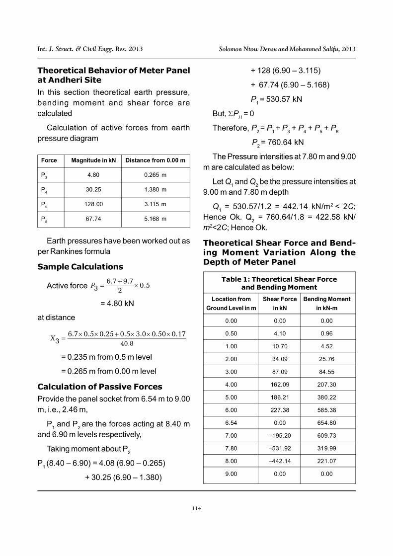
Theoretical Behavior of Meter Panelat Andheri Site
In this section theoretical earth pressure,bending moment and shear force arecalculated
Calculation of active forces from earthpressure diagram
Earth pressures have been worked out asper Rankines formula
Sample Calculations
Active force 5.02
7.97.63 P
= 4.80 kN
at distance
8.4017.050.00.35.025.05.07.6
3X
= 0.235 m from 0.5 m level
= 0.265 m from 0.00 m level
Calculation of Passive Forces
Provide the panel socket from 6.54 m to 9.00m, i.e., 2.46 m,
P1 and P
2 are the forces acting at 8.40 m
and 6.90 m levels respectively,
Taking moment about P2,
P1 (8.40 – 6.90) = 4.08 (6.90 – 0.265)
+ 30.25 (6.90 – 1.380)
Force Magnitude in kN Distance from 0.00 m
P3
4.80 0.265 m
P4
30.25 1.380 m
P5
128.00 3.115 m
P5
67.74 5.168 m
+ 128 (6.90 – 3.115)
+ 67.74 (6.90 – 5.168)
P1 = 530.57 kN
But, PH = 0
Therefore, P2 = P
1 + P
3 + P
4 + P
5 + P
6
P2 = 760.64 kN
The Pressure intensities at 7.80 m and 9.00m are calculated as below:
Let Q1 and Q
2 be the pressure intensities at
9.00 m and 7.80 m depth
Q1 = 530.57/1.2 = 442.14 kN/m2 < 2C;
Hence Ok. Q2
= 760.64/1.8 = 422.58 kN/m2<2C; Hence Ok.
Theoretical Shear Force and Bend-ing Moment Variation Along theDepth of Meter Panel
Location from Shear Force Bending Moment
Ground Level in m in kN in kN-m
0.00 0.00 0.00
0.50 4.10 0.96
1.00 10.70 4.52
2.00 34.09 25.76
3.00 87.09 84.55
4.00 162.09 207.30
5.00 186.21 380.22
6.00 227.38 585.38
6.54 0.00 654.80
7.00 –195.20 609.73
7.80 –531.92 319.99
8.00 –442.14 221.07
9.00 0.00 0.00
Table 1: Theoretical Shear Forceand Bending Moment

115
Int. J. Struct. & Civil Engg. Res. 2013 Solomon Ntow Densu and Mohammed Salifu, 2013
Maximum Theoretical Deflection
The deflection of the pile wall was calculatedusing moment area method. Therefore, thedeflection of the top of the wall is given by,
Deflection at x = 0
at top =
54.654
54.68.65414EI ...(3)
where E = 25 x 106 kN/m2
I = 0.018 m4
at top = 12.44 mm
< L/250 = 36 mm
Hence Maximum Theoretical deflection iswithin limits.
Design of Meter Panel at AndheriSite
The panel is designed for maximum bendingand shear forces and reinforcement is workedout, which is as shown in Figure 9.
Precautions in Meter PanelConstruction
The verticality of the wall is the most importantaspect of meter panel construction. Theverticality can be ensured by adopting DMCmethod for developing the bore or by ensuringthat wire rope to which chisel/bailer is attachedis always in the centre of rectangular guidecasing at the top. It is essential to scrup-ulouslymonitor the verticality of the meter panel duringconstruction.
During concreting it is advisable to takesoundings regularly so as to know the build uplevel particularly, if depth is more than 10 m.
It is preferable to use temporary casing upto a depth of 3 m. As most of the subways aregoing to be less than 7 m in depth including
depth of the road element, the problem ofverticality is not so serious.
Other components of road construction canbe carried out as routine.
Measurement of Deflections inMeter Panel Walls
The behavior of meter panel can be monitoredby measuring the actual deflection or theinward movement of meter panel wall betweenthe excavated sides and comparing it with thetheoretical deflection.
To measure lateral movement of earth workand structures, an Inclinometer is used. It provi-des the pattern of deformation, zones ofpotential danger and the effectiveness ofconstruction control measures taken. Properevaluation of inclination helps in monitoring thebehavior after construction and indicatespotentially dangerous conditions that mayadversely affect the stability of the structure.
Apart from the deflection, the otherimportant parameter of meter panel design isthe moment it is subjected to. If the bendingstresses developed are measured, then it willbe possible to project a bending momentcurve from the readings of bending strainscollected during the excavation operation.
Another way of measuring deflectioncomprises marking the centre line on thecapping beam with a Node Point at every 5m. The vertical and horizontal co-ordinates ofeach node point can be established with thehelp of a total station before the commence-ment of excavation. These readings can berepeated on achieving standard excavationdepth of the order of 3 m to 5 m. The differencebetween the two readings gives the inward

116
Int. J. Struct. & Civil Engg. Res. 2013 Solomon Ntow Densu and Mohammed Salifu, 2013
Figure 6: Theoretical Earthpressure at Andheri Site
Excavation level
P3 at 0.265m
P4 at 1.380m
P5 at 3.115m
P6 at 5.186
6.7 KN/m2
9.7 KN/m2
9.7 KN/m2
30.7KN/m2
42.0N/m2
86.0KN/m2
16.8KN/m2
50.9KN/m2
422.58KN/m2
422.58KN/m2
442.14KN/m2
442.14KN/m2<2C
P1 at 8.4m
P2 at 6.9 m
0.00
2.00
4.00
7.80
9.0
0.50
6.00
Note: * Drawing not to the scale.
Figure 7: Theoretical Shear ForceDiagram at Andheri Site
Shear Force Diagram
0, -6.54
-9
-8
-7
-6
-5
-4
-3
-2
-1
0
-600 -400 -200 0 200 400
Shear force in KN
De
pth
in
m
Figure 8: Theoretical Bending MomentDiagram at Andheri Site
Bending Moment Diagram
0
0.96
4.52
25.76
84.55
207.3
380.22
585.38
654.8
609.73
319.99221.07
0-9
-8
-7
-6
-5
-4
-3
-2
-1
0
0 100 200 300 400 500 600 700
Bending moment KN-m
Dep
th i
n m

117
Int. J. Struct. & Civil Engg. Res. 2013 Solomon Ntow Densu and Mohammed Salifu, 2013
movement of the wall towards excavation. Thismonitoring should preferably be continued tillthe comple-tion of underground constructionactivity and a good data will be availableregarding the deflections.
CONCLUSIONi) From the discussion above, the innovative
method is ideally suitable for theconstruction of subways in metropolitancities or on busy expressways. The meterpanel method is a cost effective and timesaving method, causing minimum ofobstruction to traffic.
ii) For projects involving river training where itis difficult to construct conventional retainingwall, the method provides the most suitablemeans to achieve the purpose of widening,deepening and bank protection.
iii)For basements in city areas, where deepexcavation is not possible due to spaceconstraint, the method is most suitable.
iv) The results have been analyzed using finiteelement programs and found to fairly tallywith the theoretical predictions. Meter panelconstruction being an underground activity,the monitoring of meter panel behavior with
Figure 9: Detail of Reinforcement in Meter Panel at Andheri Site
respect to the deflections and deformationsshould be regularly done. Such an activitywill give advance warning signals in caseof any ensuing problems. Monitoring thebehavior of meter panels also helps ingetting a clearer understanding of thebehavior of laterally loaded meter panelswhen subjected to actual loads.
REFERENCES1. Charles W W, Ng Douglas B R, Sean W
L Ng and G H Lei (2000), “Field Studiesof Well Instrumented Barrette in HongKong”, Journal of GeotechnicalEngineering and EnvironmentalEngineering, Vol. 1, pp. 60-72.
2. Charles W W and Ng G H Lei (2003),“Performance of Large RectangularBarrettes in Granitic Sapolites”, Journalof Geotechnical Engineering andEnvironmental Engineering, ASCE, Vol.129, No. 8, pp. 685-696.
3. Clough G W and Davidsor R R (1977),“Effects of Construction on GeotechnicalPerformance”, Proceeding of the 9th
International Conference on SoilMechanics Tokyo.

118
Int. J. Struct. & Civil Engg. Res. 2013 Solomon Ntow Densu and Mohammed Salifu, 2013
4. Day R A (1999), “Net Pressure Analysisof Cantilever Sheet Pile Wall”, Geo-technique, Vol. 49, No. 2, pp. 231-245.
5. Dunn Cliff 1 (1988), “GeotechnicalInstrumentation For Monitoring FieldPerformance, John Wiley and Sons.
6. Ganpule R S and Ganpule V T (1995),“Engineering Properties of GeologicalFormations in and Around Bombay”,European Conference on Soil Mechanicsand Foundation Engineering, Copem-hagen.
7. Ganpule V T and Borade S A (2003),“Meter Panel Construction: A UniqueSolution for Basements and Subways”, Fourth Regi-onal SymposiumInfrastructure Develop-ment in CivilEngineering (RSID), Bangkok, Thailand.
8. Kind J W (1985), “Analysis of Cantilever
Sheet pile in Cohesion Less Soils”,Journal Geotechnical Engineering, Vol.121, No. 9, pp. 629-634.
9. Ramaswamy S D and Pertusier E M(1986), Construction of Barrettes for HighRise Foundation”, Journal of Construc-tion Engineering, ASCE, Vol. 112, No.4, pp. 455-462.
10. Tomlinson M 1 (1992), FoundationDesign and Construction, LongmanPublication William F Riley, James WDally.
11. Winterkorn H F and Fang H Y (1975),Foundation Engineering Handbook.
12. Zhang I M (2003), “Behavior of LaterallyLoaded Large-Section Barrette”, Journalof Geotechnical Engineering andEnviron-mental Engineering, ASCE, pp.639-648.