meter, modulation me-57a/u (nsn 6625-00-432-7312)
TRANSCRIPT

TM 11-6625-2629-14&P
TECHNICAL MANUAL
OPERATOR’S,
DIRECT SUPPORT
ORGANIZATION
AND GENERAL SUPPORT
MANUALMAINTENANCE
INCLUDING REPAIR PARTS AND SPECIAL TOOLS LISTS
METER, MODULATIONME-57A/U
(NSN 6625-00-432-7312)
HEADQUARTERS, DEPARTMENT OF THE ARMY
30 MAY 1975

WARNING
Be careful when working on the 115- or 230-volt ac line connections and theB + supply circuits. Serious injury or death may result from contact withthese voltages.
CAUTION
Insure the DEVIATION RANGE-KC switch is in the 1000 TUNE positionbefore energizing the equipment or damage to the DEVIATION meter mayresult .
WARNING
DON’T TAKE CHANCES!
Tube type 5651 WA used in this test set contains radioactive material.This tube is potentially hazardous when broken; see qualified medicalpersonnel and the Safety Director if you are exposed to or cut by brokentubes. Be extremely careful when replacing these tubes (para 4-13) andfollow the safety procedures in their handling, storage, and disposal.
Never place radioactive tubes in your pocket.Use extreme care not to break radioactive tubes while handling them.Never remove radioactive tubes from cartons until ready to use them.

TM 1l-6625-2629-14&P
TECHNICAL MANUAL
No. 11-6625-2629-14&P
CHAPTER
Section
CHAPTER
Section
CHAPTER
Section
CHAPTER
Section.
CHAPTER
Section
CHAPTER
CHAPTER
Section
APPENDIX
APPENDIX
Section
Group
1.I.
II.
2.I.
II.
3.I.
II.
4.I.
II.III.IV.V.
5.I.
II.
6.
7.I.
II.III.IV.
A.
B.
I.II.00.
HEADQUARTERSDEPARTMENT OF THE ARMYWASHINGTON , D.C. ,30 May 1975
OPERATOR’S, ORGANIZATIONAL, DIRECT SUPPORT,
AND GENERAL SUPPORT MAINTENANCE MANUAL
INCLUDING REPAIR PARTS AND SPECIAL TOOLS LISTS
M E T E R , M O D U L A T I O N M E - 5 7 A / U
( NSN 6625-00-432-7312)
Current as of 10 April 1975
Paragraph Page
INTRODUCTIONGeneralDescription and data
SERVICE UPON RECEIPT AND INSTALLATIONService upon receipt of materialInstallation instructions
OPERATING INSTRUCTIONSControls and instrumentsOperation under usual conditions
OPERATOR AND ORGANIZATIONAL MAINTENANCE INSTRUCTIONSTools and equipmentPainting instructionsPreventive maintenance checks and servicesTroubleshootingMaintenance of modulation meter
FUNCTIONING OF EQUIPMENTGeneralCircuit theory
DIRECT SUPPORT MAINTENANCE INSTRUCTIONS
GENERAL SUPPORT MAINTENANCE INSTRUCTIONSGeneralT o o l s , t e s t e q u i p m e n t a n d t r o u b l e s h o o t i n g M a i n t e n a n c e , a l i g n m e n t , a n d c a l i b r a t i o nG e n e r a l s u p p o r t t e s t p r o c e d u r e s
R E F E R E N C E S
OPERATOR’S, ORGANIZATIONAL, DIRECT SUPPORT AND GENERAL SUPPORTMAINTENANCE REPAIR PARTS AND SPECIAL TOOLS LIST (INCLUDING DEPOTM A I N T E N A N C E R E P A I R P A R T S A N D S P E C I A L T O O L S )
I n t r o d u c t i o nRepair Parts listModu la t i on Me te r ME-57A/U Transit caseM o d u l a t i o n m e t e rF ron t pane l a s semblyT e r m i n a l b o a r d a s s e m b l i e s .R a d i o f r e q u e n c y o s c i l l a t o r
1-11-7
2-12-4
3-13-3
4-14-34-54-74-9
5-15-3
6-1
7-17-4
7-147-27
Page
A-1
B-1B-5B-5B-5B-7
B-10B-13B-16
1-11-1
2-12-2
3-13-2
4-14-14-14-34-3
5-15-3
6-1
7-17-1
7-127-18
IllustrationFigure
B-lB-2B-3B-4B-5B-6
i

TM 11-6625-2629-14&P
IllustrationPage Figure
Intermediate frequency transformer . . . . . . . . . . . . . . . . . . . . . . . . . . . . . . . . . . . . . . . . . . B-18 B-7Intermediate frequency transformer . . . . . . . . . . . . . . . . . B-19 B-8Intermediate frequency transformer . . . . . . . . . . . . . . . . . . . . . . . . B-19 B-9Intermediate frequency transformer . . . . . . . . . . . . . . . . . . . . . . . . . . . . . B-23 B-10
Section III. Special tools list (Nonapplicable).IV. FSN, Part No. Index. . . . . . . . . . . . . . . . . . . . . . . . . . . . . B-27
APPENDIX C. MAINTENANCE ALLOCATION . . . . . C-1
INDEX . . . . . . . . . . . . . . . . . . . . . . . . . . . . . . . . . Index 1
i i
,
TM 11-6625-2629-14&P
-
Number
1-1.
2-1.
2-2.3-1.
4-1.
5-1.
7-1.
7-2.
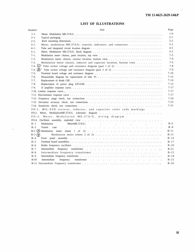
LIST OF ILLUSTRATIONS
Title
Meter, Modulation ME-57A/U . . . . . . . . . . . . . . . . . . . . . . . . . . . . . . . . . . . . . . . . . . . . . . .Typical packaging . . . . . . . . . . . . . . . . . . . . . . . . . . . . . . . . . . . . . . . . . . . . . . . . . . . . . . . . . .Rack mounting dimensions. . . . . . . . . . . . . . . . . . . . . . . . . . . . . . . . . . . . . . . . . . . . . . .
Meter, modulation ME-57A/U, controls, indicators, and connectors . . . . . . . . . . . . . .
Tube and integrated circuit location diagram . . . . . . . . . . . . . . . . . . . . . . . . . . . . . . . . . . .Meter, Modulation ME-57A/U, block diagram . . . . . . . . . . . . . . . . . . . . . . . . . . . . . . . . .
Modulation meter chassis, parts location, top view . . . . . . . . . . . . . . . . . . . . . . . . . . . . .
Modulation meter chassis, resistor location, bottom view . . . . . . . . . . . . . . . . . . . . . . . .
7-3. Modulation meter chassis , inductor and capacitor location, bottom view . . . . . . . . . . .7-4. Tube socket voltage and resistance diagram (part l of 2) . . . . . . . . . . . . . . . . . . . . .
7-4. Tube socket voltage and resistance diagram (part 2 of 2) . . . . . . . . . . . . . . . . . . . . . . . .7-5. Terminal board voltage and resistance diagram . . . . . . . . . . . . . . . . . . . . . . . . . . . . . . .
7-6. Disassembly diagram for replacement of tube Vl . . . . . . . . . . . . . . . . . . . . . . . . . . . . .
7-7. Replacement of diode CRl . . . . . . . . . . . . . . . . . . . . . . . . . . . . . . . . . . . . . . . . . . . . . . . . .7-8. Replacement of power plug UP131M . . . . . . . . . . . . . . . . . . . . . . . . . . . . .
7-9. If amplifier response curve. . . . . . . . . . . . . . . . . . . . . . . . . . . . . . . . . . . . . . . . . . . .
7-10. Limiter response curve.... . . . . . . . . . . . . . . . . . . . . . . . . . . . . . . . . . . . . . . . . . . . .
7-11. Discriminator response curve . . . . . . . . . . . . . . . . . . . . . . . . . . . . . . . . . . . . . . . . . . . . . .
7-12. Frequency range check, test connections . . . . . . . . . . . . . . . . . . . . . . . . . . . . . .
7-13. Deviation accuracy check, test connections . . . . . . . . . . . . . . . . . . . . . . . . . . .
7-14. Sensitivity check, test connections . . . . . . . . . . . . . . . . . . . . . . . . . . . . . . . . .
F O - 1 . M I L - S T D r e s i s t o r , i n d u c t o r , a n d c a p a c i t o r c o l o r c o d e m a r k i n g sFO-2. Meter, ModulationME-57A/U, schematic diagram . . . . . . . . . . . . . . . . . . .
F O - 3 . M e t e r , M o d u l a t i o n M E - 5 7 A / U , w i r i n g d i a g r a m
FO-4. Oscillator assembly, exploded view . . . . . . . . . . . . . . . . . . . . . . . . . . . .
B - l Modulation MeterME-57A/U.. . . . . .
B - 2 Transit case. . . . . . . . . . . . . . . . . . . . . . .
B-3 Modulation meter (sheet l of 2) . . . . . . . . . . . .. . . . . . . . .
B-3 Modulation meter (sheet 2 of 2) . . . . . . . . . . . . . . . . . . . . . . . . . . . . .
B - 4 Front panel assembly . . . . . . . . . . . . . . . . . . . . . . . . .
B - 5 Terminal board assemblies. . . . . . . . . . . . . . . . . . .. . . . . . . . . . . . . . . . . . . . . . . . . . . . . . . . . ..
B - 6 Radio frequency oscillator . . . . . . . . . . . . . . .. . . . . . . . . . . . . . . . . . . . . . . . . . .
B - 7 Intermediate frequency transformer . . . . . . . . .. . . . . . . . . ....
B - 8 I n t e r m e d i a t e f r e q u e n c y t r a n s f o r m e r . . . . . . . . . . . . . . . . . . . . . . . . .
B - 9 Intermediate frequency transformer . . . . . . . . . . . . . . . . . . . . . . . . . . . . . . .. . . .. . . . . .
B-10 Intermediate frequency transformer . . . . . . . . . . . . .
B-11 Intermediate frequency transformer . . . . . . . . . . . . . . . . . . . . . . . . . . . . . . . . . ..
Page
1-02-1
2-2
3-2
4-5
5-2
7-37-4
7-57-8
7-97-10
7-137-14
7-15
7-17
7-17
7-17
7-24
7-25
7-31
B - 6
B - 8
B-11
B-12
B - 1 4
B - 1 7B - 2 0
B-21B - 2 2
B - 2 4
B - 2 5
B - 2 6
iii

TM 11-6625-2629-14&P
LIST OF TABLES
Number
3-14-1
4-2
4-3
7-17-2
7 - 37-4
7-5
Title
Controls and indicators . . . . . . . . . . . . . . . . . . . . . . . . . . . . . . . . . . . . . . . . . . . . . . . . . . . . . .
Operator’s preventive maintenance checks and services . . . . . . . . . . . . . . . . . . . . . . . . . .
Organizational preventive maintenance checks and services . . . . . . . . . . . . . . . . . . . . . .
Organizational troubleshooting . . . . . . . . . . . . . . . . . . . . . . . . . . . . . . . . . . . . . . . . . . . . . . .
Required test equipment . . . . . . . . . . . . . . . . . . . . . . . . . . . . . . . . . . . . . . . . . . . . . . . . . . . . .
Resistance measurements . . . . . . . . . . . . . . . . . . . . . . . . . . . . . . . . . . . . . . . . . . . . . . . . . . . .General support troubleshooting chart . . . . . . . . . . . . . . . . . . . . . . . . . . . . . . . . . . . . . . . .
Audio amplifier stage gain. . . . . . . . . . . . . . . . . . . . . . . . . . . . . . . . . . . . . . . . . . . . . . . . . . .
Transformer and coil dc resistance . . . . . . . . . . . . . . . . . . . . . . . . . . . . . . . . . . . . . . . . . . . .
Page
3-1
4-24-2
4-4
7-1
7-2
7-6
7-117-12
iv


TM 11-6625-2629-14&P
Figure 1-1. Meter, Modulation ME-57A/U
1-0

TM 11-6625-2629-14&P
CHAPTER 1
INTRODUCTION
Section I. GENERAL
1-1. Scopea. This manual describes Meter, Modulation
ME-57A/U (fig. 1-1) and provides instructionsfor operation, organizational maintenance, directsupport (DS) maintenance, and general support(GS) maintenance. Instructions are provided forthe operator and the organizational repairman forinstallation, operation, preventive maintenanceand rep lacement o f pa r t s ava i l ab le a torganizational maintenance. Circuit functioningis included for general support maintenance,together with instructions appropriate to thatcategory of maintenance for troubleshooting,testing, adjusting, aligning and repairing theequipment and replacing maintenance parts.There are no maintenance functions for the ME-57A/U assigned to the direct support level.
b. Throughout this manual, Meter, ModulationME-57A/U will be referred to as the modulation
- meter. Specific meters within the equipment arereferred to by the associated front panelmarkrngs.
c. Appendixes B and C are current as of 10April 1975.
1-2. Indexes of Equipment Publicationsa. DA Pam 310-4. Refer to the latest issue of
DA Pam 310-4 to determine whether there arenew additions, changes , o r additionalpublications pertaining to the equipment.
b. DA Pam 910-7. Refer to DA Pam 310-7 todetermine whether there are modification workorders (MWO's) pertaining to the equipment.
1-3. Forms and Recordsa. Reports of Maintenance and Unsatisfactory
Equipment. Maintenance forms, records, andreports which are to be used by maintenancepersonnel at all maintenance levels are listed inand prescribed by TM 38-750.
b. Report of Packaging and HandlingDeficiencies. Fill out and forward DD Form 6(Packaging Improvement Report) as prescribedin AR 700-58/NAVSUPINST 4030.29/AFR 71-13/MCO P4030.29A, and DSAR 4145.8.
c. Discrepancy in Shipment Report (DISREP)(SF 361). Fill out and forward Discrepancy inShipment Report (DISREP) (SF 361) asp resc r ibed in AR 55-38/NAVSUPINST4610.33A/AFM 75-18/MCO P4610.19B, andDSAR 4500.15.
d. Administrative Storage. For procedures,forms and records, and inspections requiredduring administrative storage of this equipment,refer to TM 740-90-1.
1-4. Destruction of Army MaterielAppropriate procedures for destruction of Armymateriel to prevent enemy use and the cir-cumstances surrounding said destruction arecovered in TM 750-244-3.
1-5. Reporting of Equipment Publication Im-provements
The reporting of errors, omissions, and recom-mendations for improving this publication by theindividual user is encouraged. Reports should besubmitted on DA Form 2028 (RecommendedChanges to Publications and Blank Forms) andforwarded direct to Commander, US ArmyElectronics Command, ATTN: AMSEL-MA-Q,Fort Monmouth, NJ 07703.
1-6. CalibrationPertinent publications on calibration of thisequipment shall be referenced. Refer to DA Pam310-4.
Section II DESCRIPTION AND DATA
1-7. Purpose and Use modulated (fro) signal generators and fm trans-The modulation meter determines the accuracy of mitters. The equipment rapidly measuresfrequency deviation calibrations of frequency deviation over a range from O to 1,000 kiloHertz
1-1

TM 11-6625-2629-14&P
(kHz) at radio frequencies (rf) from 20 to 1,000megaHertz (MHz). The modulation frequencymay be from 50 to 70,000 Hertz (Hz). Theequipment operates on either 115 or 230 voltsalternating current (at), ± 10 percent, 50 to 420Hz.
1-8. DescriptionThe modulation meter (see fig. 1-1 ) consists of apanel-chassis assembly with a removablelouvered dust cover. The dust cover is attached tothe chassis with four captive screws at the rear.The equipment may be rack mounted in astandard 19-inch-wide equipment rack. Alloperating controls and connections are located onthe front panel. The power cord is permanentlyattached to the chassis and a plug storagereceptacle is provided at the lower right side ofthe front panel. The modulation meter is shippedin a metal transit case. The lid for the transit casehas compartments for the running spares.1-9. Differences Between ModelsThe modualtion meter described in this technicalmanual was manufactured under type designationME-57A/U. Previously manufactured units weredesignated ME-57/U. These units are similar inappearance, function, and technical capability.As a very brief synopsis of physical and electricaldifferences: ME-57A/U employs an integratedcircuit in place of four if. amplifiers of the ME-57/U; ME-57A/U employs improved tube types;ME-57A/U incorporates all field modificationsapplicable to the ME-57/U; and the ME-57A/Uincludes circuit changes to accommodate theintegrated circuit and other minor circuit im-provements. Technical data for ME-57/U iscovered in TM 11-6625=400-12 and TM 11-6625-400-35.
1-10. System ApplicationThe modulation meter may be used as a portabletest equipment for general use or may be per-manently mounted in an equipment rack with atransmitter to provide a constant check of theperformance of that transmitter.
1-11. Tabulated DataNumber of tubes 13Number of integrated
circuits 1Frequency, rf:
Band A 20 to 55 MHz.Band B 55 to 120 MHz.Band C 120 to 250 MHz.
Band D . . . . . . . . . . . .Band E . . . . . . .
If . . . . . . . . . . . . . . . . . . . .Deviation, . . . . . . . . . . . . . .
full-wale
250 to 500 MHz.500 to l,000 MHz.12 MHz20, 50, 100, 300, 1,000 kHz.
Modulating frequencies . .
Input sensitivity . . . . . . . . .Input impedance . . . . . . . .Voltage standing . . . . . . . . . .
wave ratioCarrier shift . . . . . . . . . . . . . .
accumcyA m p l i t u d e m o d u l a t i o n . ,
Stability . . . . . . . . . . . . . .
Audio output . . . . . . . .
Audio distortion .
Noise and hum.... .
Power input . . .requirements
P o w e r c o n s u m p t i o nWeight ., . . . . . . . . .Environment
TemperatureOpera t i ng . . . . . . . .
Storage . . . . . . . .
Humidity . . . . . . . . . .
50 to 20,000 Hz, with carrierfrequencies of 20 to 100MHz, 250 to 70,000 Hz, withcarrier frequencies of 100 to1,000 MHz
0.005 volt required for limiting50 ohmsL e s s t h a n l . 3 t o l o v e r t h e
range of 20 to 1,000 MHz10% of indicated value
Operation wi th ampl i tudemodulation of 50% is notaffected
Local oscillator drift does notexceed 200 cps l fter 30-minute warmup
1 volt ac rms corresponding to40 kHz deviation on the 0.50kHz deviation mnge
Harmonic distortion does notexceed 0.5 percent up to 900-kHz deviation
63 dB below 1 volt at 40-kHzdeviation
1 1 5 or 230 volts ( 10), 50to 420 Hz
140 watts57 lb
–4°F to +125°F(–20”C to +51.6”C)
–65°F to +160”F(–54°C to +73”C)
To 95% (non-conducting)
1-14. Items Comprising An Operable EquipmentThe ME--57A/U is a self-contained test set. Themodulation meter measures approximately 19inches wide, 10% inches high, and 14½ inchesdeep. The modulation meter is provided with atransit case that measures approximately 22 YS
inches wide, 14 Y: inches deep, 16-3/8 inches high,and weighs approximately 18 pounds (75 poundswith modulation meter contained inside).
1-2

TM 1l-6625-2629-14&P
CHAPTER 2
SERVICE UPON RECEIPT AND INSTALLATION
Section I. SERViCE UPON RECEIPT OF MATERIAL
2-1. SitingThe modulation meter is an item of portable (orrack mountable) test equipment. It is not in-tended for outdoor locations unless protectedfrom sun, rain, etc, or under environmentalconditions hostile to human habitation. Normaloperation can be expected with ambient tem-peratures and humidity levels as indicated inparagraph 1-1.
2-2. Unpackinga. Packaging Data. When packed
the modulation meter is placed infor shipment,a waterproof
carton and packed in a wooden packing case. Atypical packing case and its contents are shown infigure 2-1.
b. Removing Contents ( Wooden PackingCase). Perform all of the procedures in (1)through (5) below when unpacking an equipmentin a wooden packing case.
(1) Cut and fold back the metal straps.CAUTION
Do not attempt to pry off the sides; thismay damage the equipment.(2) Remove the nails from the cover and one
side of the wooden packing case with a nailpuller.Remove the cover and one side.
(3) Open the moistureproof barrier thatcovers the outer corrugated carton. Remove thecarton.
(4) Open the outer corrugated carton and themoisture-vaporproof barrier within the carton.Remove the inner corrugated carton.
(5) Open the inner corrugated carton andremove the instrument.
Figure 2-1. Typical packaging.
2-3. Checking Unpacked Equipmenta. Inspect the equipment for damage incurred
during shipment. If the equipment has been
2-1

TM 1l-6625-2629-14&P
damaged, report the damage on DD Form 6 (para c. Check to see whether the equipment has been1-3). modified. (Equipment which has been modified—
b. Check the equipment against packing slip to will have the MWO number on the front panel,see if the shipment is complete. Report all near the nomenclature plate. ) Check also to seediscrepancies in accordance with the instructions whether all currently applicable MWO’s haveof TM 38-750. The equipment should be placed in been applied. (Current MWO’s applicable to theservice even though a minor assembly or part that equipment are listed in DA Pam 310-7. )does not affect proper functioning is missing.
Section II. INSTALLATION INSTRUCTIONS
2-4. Assembly and Installation has sufficient ventilation
a. The modulation meter is fully assembled subject to excessive heatwhen shipped. It may be used as a free-standing equipment in the rack.test equipment on a work bench or may be (2) Mount the modulationmounted in a standard 19-inch relay rack. eight screw-slot locations.
and is notfrom other
meter using all
b. To install the modualtion meter in anequipment rack, proceed as follows:
(1) Refer to figure 2-2 and drill and tap theholes for eight mounting screws.
NOTESMost equipment racks have tapped holesat regular intervals to match the slots onthe modulation meter front panel.Choose an equipment rack location that
(3) Locate a power receptacle convenient tothe modulation meter.
(4) Set the modulation meter line voltageselection switch to match the available power(para 3-3).
(5) Insert the modulation meter power pluginto the receptacle and perform the operator’scheckout procedure (para 4-9).
2-2 Figure 2-2, Rack mounting dimensions.

TM 11-6625-2629-14&P
2-5. Interconnections plug, an indicator or earphones at the AUDIONo cable connections are necessary for operation OUTPUT binding posts (if desired), and an rfof the modulation meter except the primary power input cable to the INPUT jack (para 3-4).
2-3


TM 11-6625-2629-14&P
CHAPTER 3
OPERATING INSTRUCTIONS
Section I. CONTROLS AND INSTRUMENTS
3-1. Damage from Improper Settings 3-2. Operator’s ControlsThe DEVIATION RANGE KC switch must be in The controls and indicators for the modulationthe 1000 TUNE position before energizing the meter are on the front panel; their functions areequipment. Failure to do so could result in described in the following chart and theirdamage to the DEVIATION meter. locations shown in figure 3-1.
Control, indicator, or connectorPOWER- switchLine voltage eelector switchPower indicator lampCARRIER SHIFT meter
LIMITING meterTUNE-FINE TUNE switch
DEVIATION meterDEVIATION RANGE-KC switch
300
FREQUENCY MC dialFREQUENCY RANGE-MC switch
TUNING knob
INPUT connector
AUDIO OUTPUT
AUDIO ADJ
Table 3-1. Controls and IndicatorsFunction
Turns modulation meter on or off.Permits operation from either 115 or 230 volts ac.Lights when POWER switch is at ON position.Indicates proper tuning and amount of shift of carrier frequency from resting
frequency due to modulation.Indicates adequate signal level when in black area.Selects display range for CARRIER SHIFT meter.Switch position ActionTUNE Set s CARRIER SHIFT me te r fo r cour se
tuning of modulation meter.FINE TUNE Sets CARRIER SHIFT meter for fine tuning
of modulation meter.Indicates amount of deviation of fm signal.Selects one of 5 display ranges for DEVIATION meter.Switch position Action
20 Sets meter to read deviation to 20 kHz.50 Sets meter to read deviation to 50 kHz.
100 Sets meter to read deviation to 100 kHz.Sets meter to read deviation to 300 kHz.
1000 TUNE Sets meter to read deviation to 1000 kHz.Calibrated to indicate carrier resting frequency of signal input in megaHertz.Selects one of 5 tuned circuits for local oscillator.Switch position Action
20-65 Provides tuning of modulation meter, with useof TUNING knob, between 20 and 55 MHz.
55-120 Provides tuning of modulation meter, with useof TUNING knob, between 55 and 120 MHz.
120-250 Provides tuning of madulation meter, with useof TUNING knob, between 120 and 250MHz.
250-500 Provides tuning of modulation meter, with useof TUNING knobs, between 250 and 500MHz.
5OO-1OOO Provides tuning of modulation meter, with useof TUNING knob, between 500 and 1000MHz.
Permits tuning of local osci l lator over i ts ent ire range when used inconjunction with FREQUENCY RANGE-MC switch.
Permits convenient coupling of signal generators and transmittal coupling coilsto modulation meter.
Permits aural monitoring of input signal modulation and monitoring ofdistortion of input signal modulation when a spectrum analyzer is used.
Permits adjustment of signal level at AUDIO OUTPUT jacks.
.
3-1

TM 11-6625-2629-14&P
Figure 3-1. Meter, Modulation ME-57A/U, controls, indicators, and connectors.
Section II. OPERATION
CAUTIONInsure that the DEVIATION RANGEKC switch is in the 1000 TUNE positionbefore energizing the equipment ordamage to the DEVIATION meter mayresult .
3-3. Preliminary Starting Procedures and InitialAdjustments
Before power is applied to the modulation meter,perform preliminary operations listed below.
u. Check the line voltage selector switch and besure that it is set to the correct liner voltage. Besure that the proper fuses are in use. Use a 2-ampere fuse for 115-volt operation, and a 1.ampere fuse for 230-volt operation.
b. Plug the modulation meter into the powersource.
c. Set the TUNE-FINE TUNE switch to theTUNE position.
d. Set the DEVIATION RANGE KC switch tothe 1000 TUNE range.
e. Set the FREQUENCY RANGE MC switch
.
UNDER USUAL CONDITIONS
to the range containing the input s ignalfrequency.
f. Set the FREQUENCY MC dial to the ap-proximate frequency of the expected signal; usethe TUNING knob.3-4. Operating Procedure
NOTEIf an abnormal indication is obtainedduring the operating procedure, refer tothe troubleshooting chart Table 4-3.
Operate the equipment as follows:a. Check the controls to be sure that they are
set as required by the preliminary startingprocedure (para 3-3).
b. Set the POWER switch to the ON positionand allow 30 minutes for warmup.
c. Measure deviation from either side of theresting frequency as follows:
(1) Connect an unmodulated carrier to theINPUT connector of the modulation meter.
(2) Rotate the TUNING knob until theCARRIER SHIFT meter indicates zero.
3-2

TM 11-6625-2629-14&P
(3) Switch the TUNE-FINE TUNE switch tothe FINE TUNE position.
(4) Rotate the TUNING knob until theCARRIER SHIFT meter again indicates zero.The FREQUENCY-MC dial now indicates thecarrier resting frequency of the input signal.
NOTEIf necessary, adjust the signal generatoroutput or vary the coupling whenmeasuring a transmitter.(5) Check the LIMITING meter to be sure
that it indicates in the black area.NOTE
Usually signal generators can be con-nected direct to the INPUT connector iftheir level is relatively low. When thedeviation of an fm transmitter ismeasured, loosely couple the output ofthe transmitter to the INPUT jack of themodulation meter with a pickup coil of afew turns.(6) Apply modulation to the carrier.(7) Rotate the DEVIATION RANGE-KC
switch without pegging the meter. TheDEVIATION meter now indicates the deviationof the carrier from its resting frequency due tomodulation. If the 1000-TUNE position is used,multiply the 0-100 scale reading on theDEVIATION meter by 10.
(8) If my shift in the resting frequency hastaken place due to the modulation, the amount ofshift will be indicated on the CARRIER SHIFTmeter.
(9) The AUDIO OUTPUT jacks can be usedfor audio monitoring of the input signalmodulation. With a spectrum analyzer connectedto the AUDIO OUTPUT jack, distortion of inputsignal modulation can be measured. The outputlevel can be varied by adjusting the AUDIO ADJcontrol.
3-5. Procedure for Placing Equipment in StandbyCondition
The modulation meter does not employ standby
facilities. If standby operation is necessary, setthe DEVIATION RANGE KC switch to 1000TUNE and leave the POWER switch ON.
3-6. Procedures for ShutdownStop the modulation meter as follows:
a. Set the DEVIATION RANGE-KC switch tothe 1000 TUNE position.
b. Set the TUNE-FINE TUNE switch to theTUNE position.
c. Set the POWER switch to OFF.3-7. Preparation for MovementThe modulation meter is provided with a transitcase to contain and protect the unit and its ac-cessories. If the modulation meter is used as areck-mounted teat equipment, proceed as follows;if used as a free-standing test equipment,disregard steps c and d
a. Disconnect any test leads (that may beconnected to AUOIO OUTPUT binding posts orINPUT connector).
b. Disconnect the main power plug.c. Remove eight screws that secure the
modulation meter to the equipment rack.CAUTION
Support the back of the modulation meterwhen the screws are removed; the unitweighs 57 pounds.
d. Withdraw the modulation meter from theequipment rack.
e. Slide the modulation meter into the transitcase, face of the modulation meter toward thecase opening.
f. Plug the power connector into PLUGSTORAGE ONLY receptacle (on the face of themodulation meter) and coil the power wire be-tween the ttransit case and the equipment.
g. Place the transit case cover in place and snapclosed the eight fasteners that secure the lid to thecase. The modulation is prepared for movementunless shipment is involved (fig. 2-1).
3-3


TM 11-6625-2629-14&P
CHAPTER 4
OPERATOR AND ORGANIZATIONAL MAINTENANCE
Section l. TOOLS AND EQUIPMENT
4-1. General a.This section contains a list of materials required b.for operator and organizational maintenance. c.Repair parts, special tools, special test equip- d.ment, and accessories prescribed for use with the e.modulation meter are listed in appendix B.
4-2. Tools and Equipment RequiredThe following tools and equipment are requiredfor maintenance of the modulation meter:
Tool Kit, Electronic Equipment TK-105/G.Trichloroethane, technical.Brush, MIL-G-7241.Fine sandpaper, No. 000.Lint-free cloth.
Section Il. REPAINTING AND REFINISHING INSTRUCTIONS
4-3. Paints and FinishesWhen Meter, Modulation ME-57A/U requiresrepainting, refinishing, or touchup painting, referto Federal Standard No. 595a for a matchingcolor. SB 11-573 lists painting tools andmiscellaneous supplies required for painting.4-4. Touchup Painting Instructions
a. Refer to TB 746-10 for instructions onpainting and preserving Electronics Commandequipment. In touchup painting a perfect matchwith the exact shade of the original paint surfacemay not be possible. There are many reasons forthis, such a change in the original pigmentbecause of oxidation and differences as a result ofmanufacture. The prevention of corrosion and
deterioration is the most important considerationin touchup painting; appearance is secondary.This, however, should not be construed to meanthat appearance of the equipment is not im-portant. Touchup paint should be accomplishedneatly and in good workmanshiplike manner.Inspection personnel in the field should makeallowances for slight color mismatch where minortouchup has been done, but not for neglect, poorworkmanship, or in cases where the need forrefinishing is obvious.
b. Remove rust and corrosion from metalsurfaces by lightly sanding them with finesandpaper. Brush two thin coats of paint on thebare metal to protect it from further corrosion.
Section III. PREVENTIVE MAINTENANCE CHECKS AND SERVICES
4-5. Generala. This section describes preventive main-
tenance checks and services which may be per-formed by operator and organizational main-tenance activities.
NOTEThe modulation meter does not requirelubrication and none is recommended.
b. To insure that the modulation meter isalways ready for operation, it must be inspectedsystematically so that defects may be discoveredand corrected before they result in serious damage
or failure. The necessary preventive maintenancechecks and services to be performed are listed anddescribed in tables 4-1 and 4-2. The item numbersindicate the sequence of an minimum inspectionrequired. Defects discovered during operation ofthe modulation meter will be noted for futurecorrection to be made as soon as operation hasceased. Stop operation immediately if a deficiencyis noted during operation which would damagethe modulation meter. Record all deficienciestogether with corrective action taken on ap-plicable forms prescribed in TM 38-750. In-
4-1
TM 11-6625-2629-14&P
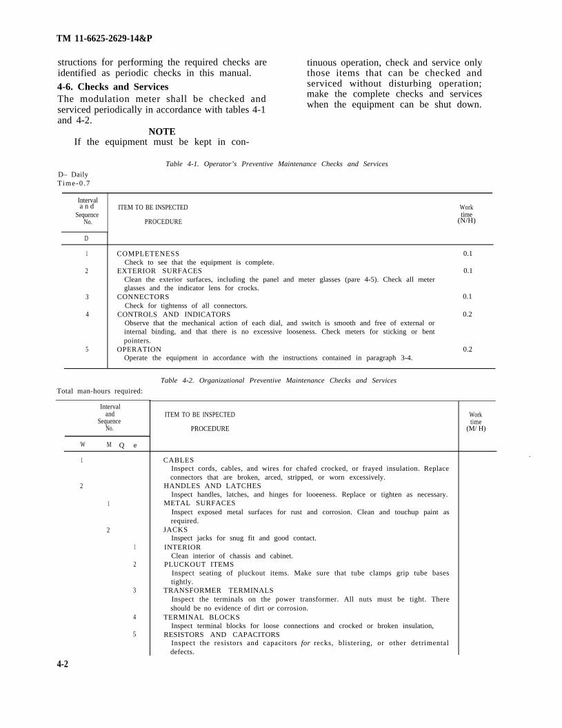
structions for performing the required checks areidentified as periodic checks in this manual.
4-6. Checks and ServicesThe modulation meter shall be checked andserviced periodically in accordance with tables 4-1and 4-2.
NOTEIf the equipment must be kept in con-
tinuous operation, check and service onlythose items that can be checked andserviced without disturbing operation;make the complete checks and serviceswhen the equipment can be shut down.
Table 4-1. Operator’s Preventive Maintenance Checks and Services
D– DailyTime-0 .7
a n dInterval
ITEM TO BE INSPECTED WorkSequence time
No. PROCEDURE (N/H)
D
1 COMPLETENESS 0.1Check to see that the equipment is complete.
2 EXTERIOR SURFACES 0.1Clean the exterior surfaces, including the panel and meter glasses (pare 4-5). Check all meterglasses and the indicator lens for crocks.
3 CONNECTORS 0.1Check for tightenss of all connectors.
4 CONTROLS AND INDICATORS 0.2Observe that the mechanical action of each dial, and switch is smooth and free of external orinternal binding, and that there is no excessive looseness. Check meters for sticking or bentpointers.
5 OPERATION 0.2Operate the equipment in accordance with the instructions contained in paragraph 3-4.
Table 4-2. Organizational Preventive Maintenance Checks and Services
Total man-hours required:
Intervaland
SequenceNo.
W M Q e
1
2
1
2
1
2
3
4
5
ITEM TO BE INSPECTED
PROCEDURE
CABLESInspect cords, cables, and wires for chafed crocked, or frayed insulation. Replaceconnectors that are broken, arced, stripped, or worn excessively.
HANDLES AND LATCHESInspect handles, latches, and hinges for looeeness. Replace or tighten as necessary.
METAL SURFACESInspect exposed metal surfaces for rust and corrosion. Clean and touchup paint asrequired.
JACKSInspect jacks for snug fit and good contact.
INTERIORClean interior of chassis and cabinet.
PLUCKOUT ITEMSInspect seating of pluckout items. Make sure that tube clamps grip tube basestightly.
TRANSFORMER TERMINALSInspect the terminals on the power transformer. All nuts must be tight. Thereshould be no evidence of dirt or corrosion.
TERMINAL BLOCKSInspect terminal blocks for loose connections and crocked or broken insulation,
RESISTORS AND CAPACITORSInspect the resistors and capacitors for recks, blistering, or other detrimentaldefects.
Worktime
(M/ H)
.
4-2

TM 11-6625-2629-14&P
Table 4-2. Organizational Preventive Maintenance Checks and Services –Continued
and Interval
ITEM TO BE INSPECTEDSequence
No. PROCEDURE
W M Q
6 GASKETS AND INSULATORSInspect gaskets, insulators, bushings, and sleeves for cracks, chipping, andexcessive wear. —
Worktime
(M/H)
Section IV. TROUBLESHOOTING
4-7. GeneralThis section contains troubleshooting in-structions for the modulation meter. Anymalfunction that is beyond the scope of theorganizational maintenance activity to correctshall be referred to general support maintenance.4-8. ProcedureWhen the modulation meter fails to operate
correctly, turn it off and check the followingitems:
a. Wrong control settings or improper inputconnections (para 3-3 and 3-4).
b. Damaged or incorrectly connected powercord. ,
c. Defective power fuse (fig. 3-1). Following theinstructions contained in paragraph 4-10.
Section V. MAINTENANCE OF MODULATION METER
4-9. General. This section contains maintenance instructions
applicable to organizational maintenance ac-tivities. Maintenance of the modulation meter bythis activity is limited to the following items:
a. Fuse and lamp replacement (para 4-10).b. Cleaning (para 4-11).c. Functional testing (para 4-12).d. Tube replacement (para 4-13).
4-10. Removal/Replacementa Replacement of Fuse (fig. 3-1).
CAUTIONDO NOT use a fuse rated above thespecified value (para 3-3). Damage to theequipment may result.(1) Turn the fuse-holder cap counterclockwise
to unlock.(2) Pull out the fuseholder cap with the
defective fuse. Remove the defective fuse andreplace it with a new one.
(3) With the new fuse installed, insert thefuseholder cap into the fuseholder. Press in on thefreeholder cap and turn it clockwise to lock.
b. Replacement of Power Indicator Lamp (fig.3-l).
(1) Unscrew (counterclockwise) the in-dicating light lens and remove it to expose thelamp.
(2) Press in on the lamp and turn it coun-terclockwise to unlock.
(3) Remove the defective lamp and replace itwith a new one. Push in on the lamp and turn itclockwise to lock.
(4) Replace the lens by screwing it on (clock-wise).4-11. CleaningInspect the exterior of the equipment. The ex-terior should be clean, and free of dust, dirt,grease and fungus.
a. Remove dust and loose dirt with a clean lint-free cloth.
WARNINGThe fumes of trichloroethane are toxic.Provide thorough ventilation wheneverused. DO NOT use near an open flame.Trichloroethane is not flammable, butexposure of the fumes to an open flameconverts the fumes to highly toxic,dangerous gases.
b. Remove grease, fungus, and ground-in dirtfrom the cases; use a cloth dampened (not wet)with trichloroethane. After cleaning, wipe drywith a clean lint-free cloth.
c. Remove dust or dirt from plugs and jackswith a soft-bristled brush.
4-3

TM 11-6625-2629-14&P
CAUTION knobs; us a soft clean lint-free cloth. IfDO NOT press on the meter face (glass) necssary, dampen the cloth with water mild soapwhen cleaning; the meter may become may b. used for more effective cleaning. Wipe dry damaged. with a clean lint-free cloth.
d. Clean the front panel, meters, l nd control
Table 4-3. Organization Troubleshooting
Malfunction
Power indicator does not light,
L I M I T I N G m e t e r d o e s n o tindicate in black l raa.
CARRIER-SHIFT meter does notindicate zero,
D E V I A T I O N m e t e r d o e s n o tdeflect.
Probable cause
4-12. Functional Testing
a. Defective fuse.b. Defective lamp.Defective vacuum tube V2.
Defective vacuum tube V2, V7, V8or V9,
Defective vacuum V10, V11, W12,V13 or V14.
The modulation meter should be checked forcorrect operation after any maintenance is per.formed. Appropriate checks are contained inparagraphs 3-4 l nd 3-6. Successful completion ofthese checks insures that the modulation meter isready for operation. Should the modulation maternot perform properly, refer to table 4-3 for thecorrective action for a particular abnormal in.dication. If the indicated corrective action doesnot correct the abnormality, the modulationmeter must be sent for higher level maintenance.
4-13. Vacuum Tube Replacement(fig. 4-1)
u. If tube failure is suspected (V2 through V18),use the applicable procedure ((1) or (2) below) toremove and replace the tubes. Replacement of V1should be made by the general support main-tenance level.
Corrective action
a. Replace fuse (pus 4-10),b. Replace lamp (para 4-10).Replace vacuum tube V2.
Replace defective vacuum tube.
Replace defective vacuum tube.
b. Removal and Replacement of Tubes.CAUTION
DO NOT rock or rotate a tube whenremoving it from a socket. pull it straightOut with a tube puller.
Tubes with shields. To remove the tubeshield, press. it down and turn it counterclockwiseto unlock, Remove the tube shield. Afterreplacing the tube, replace the tube shield bypressing the tube shield down and turning itcbckwise until it locks in place.
(2) Tubes with retainers. To remove the tuberetainer, compress the spring portion of theretainer that fits on the post and lift up. Afterreplacing the tube; place the retainer over thepost, compress the spring, and fit the retainerover the tube by lowering it on the post. When theretainer is in its proper position, release thespring.
4-4

Figure 4-1.
TM
11-6625-2629-14&
P
4-5


TM 11-6625-2629-14&P
CHAPTER 5
FUNCTIONING OF EQUIPMENT
5-1. IntroductionThe modulationreceiver which iscarrier shift of
Section I. GENERAL
and is mounted on top of the chassis. It providesmeter is essentially an fm a signal to mix with the incoming radio frequency
used to measure deviation and (rf) signal. The modulation meter input frequencyfrequency modulated signal is covered in five ranges selected by the
generators and transmitters. In brief it operates FREQUENCY RANGE-MC switch,by converting the incoming radio frequency b. Mixer CR1. The mixer is mounted on thesignals to a controlled-amplitude (adjustable back of the oscillator. A crystal diode is used tolimited) intermediate frequency, employs a mix the radio of signal with the oscillator signal.discriminator to detect the modulation (or The resulting intermediate frequency (if) signal isdeviation), a precision divider network to provide fed to the if amplifier/limiter section consisting ofwide measurement range, an adjustable-gain VI, Ul, V7, and V8.amplifier to drive output circuits, and poweramplifiers to drive a deviation meter and audiooutput jack.
5-2. Block Diagram Description(fig. 5-1)
a. Oscillator V1. The oscillator is self-contained
5-1

Figure 5-1.
TM
1
1-6
62
5-2
62
9-1
4&
P
5-2

TM 11-6625-2629-14&P
c. If Amplifier V2. The if amplifier rejectsundesired output frequencies of the mixer and
. provides primary amplification at the 12 MHzintermediate frequency which is fed to integratedcircuit U 1.
d. If Amplifier and Limiter U1. The if amplifierand limiter possesses very high gain and a self-
. limiting capability at moderate input signallevels. It has the ability to accommodate a widerange of input signal level, and eliminates theneed for automatic volume control (avc) elsewherein the circuit.
e. Limiters V7 and V8. Two cascaded limiterstages use high conductance pentodes to achievefurther limiting of the if signal. They are broad-band tuned and the output of V8 is fed to thedriver amplifier circuit.
f. LIMITING Meter M1. The LIMITING meteris fed from the second limiter stage. When themeter pointer is in the back range, it indicates thatthe level of the rf input is sufficient for properoperation of the modulation meter.
g. Driver Amplifier V9. The driver amplifieramplifies the limited if signal to the level requiredfor optimum discriminator operation.
h. Discriminator T9. The discriminator con-verts the frequency-modulated if signal tovoltages corresponding to the amount ofmodu la t ion app l i ed to the s igna l . Thediscriminator output is fed to CARRIER SHIFTmeter M2 and audio circuits.
i. CARRIER SHIFT Meter M2. Meter M2 is azero-center meter that indicates the amount ofcarrier shift caused by the modulation of the rfsignal. Readings are in kiloHertz (kHz).
j. Divider Network. This precision divider isused to select the amount of signal required forfull-scale readings on the DEVIATION meter, asset by the DEVIATION RANGE-KC switch. Thesignal is then fed to the audio amplifiers.
k. Audio Amplifiers V10 through V13. Theaudio amplifiers are resistance-capacitance (rc)coupled stages with cathode follower input andoutputs. The band-pass is flat up to 70,000 Hertz(Hz). The output is fed to the DEVIATION meterand the AUDIO OUTPUT binding posts.
l. DEVIATION Meter M3. This three-scale,five-range meter indicates deviation of fm signalgenerator or transmitter output.
m. Power Supply. Full-wave rectification isaccomplished by a bridge rectifier consisting ofCR8 through CR11. It has an unregulated 240-volt dc output. A regulated 195-volt dc output isobtained by the use of voltage regulator stageV17, direct current (de) amplifier stage V16, and aseries regulator stage V15. Ballast tube V14provides a regulated filament voltage for use withoscillator V1 and audio output cathode followerV13. Zener diode CR12 provides 10.1-volts dcregulated as operating voltage to integratedcircuit V1. The regulated +195-volt dc supply isthe power source for zener diode regulator CR12.
Section II. CIRCUIT ANALYSIS
5-3. GeneralParagraphs 5-4 through 5-10 provide detailedanalysis of the modulation meter. Figure FO-2 isthe schematic diagram and figure FO-3 is thewiring diagram which represent the ME-57A /U.
5-4. Oscillator VI(fig. FO-2)
u. The local oscillator generates a signal that isfed to the mixer to be mixed with the incomingsignal from a frequency-modulated signalgenemtor or transmitter. The oscillator is tunableover a range from 32 through 512 MegaHertz(MHz) in five bands, which are selected by theF R E Q U E N C Y R A N G E - M C s w i t c h . T h efrequency of the oscillator signal is always 12MHz higher than the incoming signal, except onthe 500-1000 range where the second harmonic ofthe oscillator is used.
b. A 5676 pencil triode is used in the shunt-fedmodified Colpitts oscillator. Regulated filament.
voltage is applied through filter network Z1.Filter network Z1 keeps all rf signals shorted toground. Plate voltage is fed through Z2, whichfunctions the same as Z1. Plate current flows onlywhen the FREQUENCY RANGE-MC switch isin one of the five frequency bands and keeps V1nonoperating while changing frequency ranges.This prevents unwanted oscillations which wouldoccur if V1 were kept operating.
c. The frequenty determining circuit is com-posed of Cl, a two-section, air-dielectric, variablecapacitor, and one o f f ive induc tances( r e p r e s e n t e d b y L B ) s e l e c t e d b y t h eFREQUENCY RANGE-MC switch. Inductancesand resistances (represented by LA and R4) areused to couple the oscillator output to the mixer.They are selected by the FREQUENCY RANGE-MC switch, and are designed to give optimumcrystal injection, Capacitor C107 and resistor R7form a grid leak bias circuit.
5-3

TM 11-6625-2629-14&P
5-5. Mixer CR1(fig. FO-2)
The crystal mixer CR1 receives the oscillatorsignal and the rf signal; the resultant if signal isfed to the first stage of if amplification. Theoscillator signal is injected through R 1, whichprovides signal separation from the localoscillator, to diode CR1.
5-6. 1st If Amplifier V2 and Integrated CircuitU1
(fig. FO-2)If amplifier stage V2 and integrated circuit U1form a high-gain, wide-band circuit operating at acenter frequency of 12 MHz with an overallbandwith of 3 MHz. The if amplifier V2 rejectsundesired output frequencies of the mixer andprovides primary amplification for integratedcircuit U1. IC U1 has the ability to accommodatea wide range of input signal level, and eliminatesthe need for automatic volume control.
5-7. Limiters V7 and V8 and Driver Amplifier V9(fig. FO-2)
Limiting is achieved by grid limiting action instages V7 and V8. The two stages are used toobtain the required amplitude-modulated (am )rejection characteristics. The signals from theamplifier stages are limited and fed to the driveramplifier stage V9. The grid return for V7 is R50,which is in series with LIMITING meter M 1.L I M I T I N G A D J c o n t r o l R 5 1 s e t s theLIMITING meter to the start of the black areawhen the signal input level to the equipment is 5millivolts. Capacitor C54 is the bypass for theLIMITING meter.
5-8. Discriminator T9(fig. FO-2)
The discriminator is a modified Fester-Steel typeand is completely enclosed in the. can for trans-former T9. The discriminator receives the signalsfrom the driver amplifier and converts the in-formation to an audio signal with its amplitudedetermined by the amount of deviation from thecarrier frequent y. This audio signal is then fed tothe audio amplifier circuits. Resistor R66broadens the response of the transformer primaryto accept 10.5 to 13.5 MHz. Capacitor C81 acts asa stabilizer to keep the dc level constant when nodeviation is present. Carrier shift indication isdisplayed on CARRIER SHIFT meter M2. Thedeflection of the meter is proportional to thevoltage at pin 3 of the discriminator. Two rangesof carrier shift are available by use of the TUNE-FINE TUNE switch S4. In the TUNE position(positions shown) of S4, the entire S-curve of the
discriminator is displayed. In the FINE TUNEposition, carrier shift up to 250 kHz is displayed.Resistors R73 and R74 are in series with the CARRIER SHIFT meter to limit current throughthe meter. Resistor R75 is a calibration poten-tiometer for the FINE TUNE position of S4.
5-9. Audio Amplifier V10, V11, V12, and V13 (fig. FO-2)
The audio amplifier circuit (V10, V11, V12, andV13) is comprised of four resistor-capacitor (rc)coupled stages. The low-distortion, high-stabilitycircuit has a cathode follower input and output.The signal inputs from the discriminator areamplified and fed to DEVIATION meter M3 andthe AUDIO OUTPUT terminals.
a. Tube V10 is the cathode follower input andfirst audio stage. Operating bias for V10A isdeveloped by the drop across R79. Attenuation ofthe audio output of V 10A is obtained by tappingoff a fixed portion of the voltage applied to thevoltage divider consisting of R78, R82, R83, R84,and R85. This effectively varies the range of theDEVIATION meter. Capacitor C85 providescoupling from V 10A cathode to the attenuatorcircuit. Coupling from the attenuator to the gridof V10B is through C86. The cathode of V10B istied to the voltage divider in the cathode of V12.The cathode voltage is raised or lowered asnecessary to give constant gain throughout theamplifier circuit. A bypass circuit in the plate ofV10B, comprised of R89 and C88, is used to shortfrequencies above the audio range to ground.Signals from the plate of V10B are coupled to thegrid of V11 through C106.
b. Tubes V11 and V12 are conventional audioamplifier stages. Operating bias for V12 isdeveloped by the drop across R105 and R106. Thejunction of R105 and R106 is the return for thecathode of B10B. Two outputs are taken from thisstage. The signal from - the plate is coupledthrough C94 to the grid of V13A. The signal fromthe junction of R103 and R104 is coupled throughC98 to the grid of V13B.
c. Tube V 13 provides two cathode followeroutput stages. The cathode load for V13A isR112. Coupling from the cathode of V13A to theDEVIATION meter rectifier circuit is throughC96. Rectification of the audio signal is achievedby CR7 and R113. Resistor R116 limits currentthrough the meter. Meter calibration is obtainedby the setting of CAL ADJ R118. Grid bias forV13B is developed by the drop across R117. Operating bias is developed by the drop acrossR115. The load for the cathode of V13B iscomprised of R119, R120, and R121. Resistor
5-4

TM 11-6625-2629-14&P
R120 is adjusted to give 1-volt root mean square(rms) out for 40-kHz deviation on the 0-5-kHzdeviation range. Capacitor C99 couples the audiooutput to the AUDIO OUTPUT binding post.Plate decoupling for V13B is through R114 andC97 .
5-10. Power Supply(fig. FO-2)
a. The 115- or 230-volt ac line voltage isstepped up by the high voltage secondary win-ding of T10. A full-wave bridge rectifier con-sisting of CR8, CR9, CR10, and CR11 providesrectification of the ac voltage. Capacitors C101,C102, and C103, and inductors L11 and L12comprise the filter network for the power supply.
b. Filtered dc voltage is applied to the plates ofseries regulator V 15. The regulated 195-voltoutput is taken from the cathode of V15. Bias forthe grids of V15 is obtained from the plate of dcamplifier V16. Part of the load for the cathode ofV15 is comprised of R126, R127, and R128. The
setting of R127 controls the fixed bias on the gridof V 16. Variation in the regulated 195 volts are.coupled through C100 to the grid of V16. Thescreen voltage for V16 is controlled by the settingof R123. Resistors R129, R123, and R192 form avoltage divider to provide the proper screenvoltage. Plate load for V 16 is R124. The cathodeof V 16 is held constant by voltage regulator V17,If the voltage varies, the change is felt on the gridof V16. Tube V 16 changes its conduction, whichvaries the bias on the series regulator V15. TubeV15 then changes the conduction to obtain thecorrect output voltage.
c. Transformer T 10 has four separate filamentwindings. The output at terminals 7 and 8 is 6.3volts ac. The power ON indicator lamp is DS1.The output at terminals 11 and 12 is fed to ballasttube V14. Resistor R131 in series with V14provides a regulated 6-volt output, which is usedfor filaments of V1 and V13.
5-5


TM 11-6625-2629-14&P
CHAPTER 6
DIRECT SUPPORT MAINTENANCE
6-1. Scope of Direct Support Maintenance NO maintenance functions for the modulation meter are assigned to the direct support level.
6-1


TM 11-6625-2629-14&P
CHAPTER 7
GENERAL SUPPORT MAINTENANCE
Section l. GENERAL
7-1. IntroductionThis chapter contains voltage and resistancemeasurement diagrams, parts location diagramsand troubleshooting information. In addition, italso contains repair and replacement information,alignment and genera l suppor t t e s t i ngprocedures.
7-2. Voltage and Resistance DiagramsThe voltage and resistance measurement in-
formation appears on figures 7-4 , 7-4 , and7-5. The specific conditions under which thisinformation was gathered are listed on thediagrams.
7-3. Parts Location and Schematic DiagramsParts locations are shown on figures 7-1, 7-2, and7-3. A schematic diagram for the overallmodulation meter is contained on figure FO-2.The overall wiring diagram is figure FO-3.
Section II. TOOLS, TEST EQUIPMENT AND TROUBLESHOOTING
7-4. Tools and Test Equipment Required equipment required for maintenance of theThis section contains a listing (table 7-1) of test modulation meter. No special tools are required.
Table 7-1. Required Test Equipment
Test equipment Common name Technical manualAnalyzer ZM-3/U Capacitor tester TM 11-5043-12Analyzer, Spectrum TS723(*)/UAudio Oscillator TS-382Crystal Rectifier Teat Set TS.
268/UCounter, Electronic Digital
Readout AN/USM-207Electronic Multimeter ME-26(*)/UGenerator, Signal SG.92/UIndicator, Panoramic ID-173/UMeter Test Set, TS-662/GSM-1Oscilloscope AN/USM.281ARf Signal Generator AN/URM-
25(*)Signal Generator, AN/USM-44Teat Set, Oscillator Set AN/PRM.
10Test Set, Electrical Meter TS-
656/UTeat Set, Electron Tube TV-2/UVoltmeter, Electronic ME-30B/U
Spectrum analyzerAudio oscillatorCrystal test set
Counter
VtvmSweep generatorPanoramic indicatorCalibration test setOscilloscopeLow frequency generator
Am generatorOscillator test set
Meter tester
GS tube teeterElectronic voltmeter
TM 11-5097TM 11-6625-261-12TM 11-1242
TM 11-6625-700.10
TM 11-6625-200-15TM 11-319TM 11.5086TM 11-2535BTM 11-6625-1703-15TM 11-5551B
TM 1143625-508-10TM 11-6625-276-10
TM 11-6625-226.12
TM 11-6625.316-12TM 11-6625-320-12
WARNING level includes all the techniques outlined for allWhen servicing the modulation meter, be lower maintenance levels and any special o rcareful when working on the ac line or dc additional techniques required to isolate avoltages. Always disconnect the power defective part. The systematic troubleshootingcord from the source before changing any procedure includes sectionalizing and localizingcomponent.
7-5. General InstructionsTroubleshooting at general
.
techniques.7-6. Organization of Troubleshooting Procedures
support maintenance a. General. The first step in servicing a
7-1

TM 11-6625-2629-14&P
defective modulation meter is to sectionalize thefault. Sectionalization means tracing the fault toa major circuit responsible for the abnormaloperation. The second step is to localize the fault.Localization means tracing the fault to a defectivecomponent which is responsible for the abnormalcondition. Some faults may be located by sight;however, the majority of the trouble must belocated by checking voltages and resistances.
b. Sectionalization. The modulation meterconsists of five main sections: the local oscillator,the intermediate frequency amplifier, thediscriminator, the audio amplifier, and the powersupply. The first step in tracing trouble is tolocate the circuit or circuits at fault as follows:
(1) Visual inspection. Visual inspection willhelp locate faults without testing or measuringcircuits. A 11 meter readings and other visual signsshould be observed and an attempt made tosectionalize the fault to a particular section.
(2) Operational tests. Operational testsfrequently indicate the general location of trouble.In many instances, the tests will help in deter-mining the exact nature of the fault.
c. Localization. The tests listed below will aidin isolating the trouble. First, localize the troubleto a single stage or circuit, and then isolate thetrouble within that circuit by voltage, resistance,and continuity measurements.
(1) Signal tracing. Signal tracing (para 7-10)will help in isolating the fault to a specific stage.
(2) Voltage and resistance measurements.Abnormal voltage or resistance measurementsmay pin-point a fault, Use resistor inductor, andcapacitor color codes (fig. FO-1) to find normalreadings and compare them with reading taken.
(3) Troubleshooting chart. The general
- — .Point of measurement
Between ground and pin 9 ofXV13.
Between ground and pin 4 ofXV16.
Between ground and pin 9 ofXV10.
Between ground and the junctionof C101A and C102. Be sure ofmeter polarity to obtain correctreading. (The higher of the tworeadings is the correct one. )Note: If using the TS-352(*)/U,the lead connected to the OHMSconnector should be grounded.
support troubleshooting chart contains symp-toms which will aid in localizing trouble to acomponent part.
(4) Intermittent troubles. In all tests, thepossibility of intermittent troubles should not beoverlooked. Usually, this type of trouble can bemade to occur by tapping or jarring the equip-ment. Check the wiring and connections toparts of the modulation meter (fig. FO-3).
7-7.
CAUTIONDo not attempt removal or replacement ofparts before reading the instructions inparagraph 7-14.
Checking Filament and B + Circuits
the
forShorts
a. When to Check. When any of the followingconditions exist, check for short circuits and clearthe troubles before applying power.
(1) When the modulation meter is beingserviced and the nature of the abnormal symp-toms is not known.
(2) When the abnormal symptoms reportedfrom operational test (para 3-4) indicate possiblepower supply troubles.
b. Conditions for Test.(1) Remove the dust cover.(2) Remove all tubes from their sockets.(3) Remove the power indicator lamp.
c. Measurements. Use the multimeter andmake the resistance measurements indicated inthe following chart. If abnormal results are ob-tained, make the additional isolating checksoutlined below. When the fault y part is found,repair the trouble before applying power to theunit.
Table 7-2. Resistance Measurements
Normal indication
Resistance should beapproximately 36 ohms.
Infinite resistance.
Infinite resistance.
Resistance should beapproximately 250K.
Isolating procedure
If resistance is zero, check for short at XV13 (fig.7-2) or shorted lead from J4 (fig. 7-1) or at Z1on the oscillator. If the resistance is infinite,check for open resistor R131 on TB6 (fig. 7-2).
If a short or finite resistance is read, check thewiring to and at sockets XV15 ami XVIG (fig. 7-2).
If a short or finite resistance is read, check thewiring to and at sockets XV10, XV11, andXV12 (fig. 7-2).
If resistance is zero, check for shorted filtercapacitor C101A or C102. If resistance isapproximately 110 ohms, check for short inC103. If resistance is approximately 165 ohms,check for short in C101 B or bypass capacitorC50, If any other resistance below 250K isobserved, check all the bypass capacitors (fig. 7-3 and FO-2).
7-2

TM 11-6625-2629-14&P
Table 7-2. Resistance Measurements – Continued
Point of measurement Normal indication Isolating procedure.
Between ground and pin 6 of Resistance should be If resistance is less than 10K, check all screenXV15. approximately 10K; reading will bypass capacitors (f ig. 7-3 and FO-2). If
be determined by set t ing of resistance is higher than 10K, check R130 forR130. open (fig, 7-2).
. 1
Figure 7-1. Modulation meter chassis, parts location, top view.
7-3

Figure 7-2.
TM
11-6625-2629-14&
P
7-4

Figure 7-3
TM
1
1-6
62
5-2
62
9-1
4&
P
7-5

TM 11-6625-2629-14&P
7-8. Test Setupa. The modulation meter measures deviation of
a frequency-modulated carrier. Some faults withthe modulation meter can be determined by usingan unmodulated carrier input. The use of anunmodulated carrier. can help determine faults inthe local oscillator, if, limiter, and discriminatorcircuits. A modulated carrier is required tocompletely check the discriminator and the audiocircuits.
b. Connect the output of the fm signalgenerator to the input connector of themodulation meter (fig. 7-13). Connect thevacuum-tube voltmeter to the audio output of themodulation meter. Use a shielded lead.
7-9. Localizing Trouble
troubleshooting chart are presented in sequenceso that the user can trace the fault to the par-ticular stage. When trouble has been traced to astage, a tube check or voltage and resistancemeasurements should disclose the defectivecomponent part,
b. Use of Chart. The troubleshooting chart isdesigned to supplement the organizationaltroubleshooting chart ( table 4-3). If nooperational symptoms are known, perform thefunctional testing (para 4-12),
CAUTIONIf operational symptoms are not known,or if they indicate the possibility of shortcircuits, check for shorts as described inparagraph 7-7.
a. General. The procedures in the
Table 7-.3. General Support Troubleshooting Chart
Symptom
1. Power indicator lamp DS1 does notlight, no filament or B+ voltage.
2. Power indicator lamp DS1 does notlight. M o d u l a t i o n m e t e r i soperative.
3. With unmodulated carrier input,LIMITING meter Ml does notr ead a t any pos i t i on o f t heF R E Q U E N C Y R A N G E - M Cswitch or TUNING control.
4. With unmodulated carrier input,LIMITING meter Ml reads atfrequency other than that ofincoming signal. FREQUENCYRANGE-MC switch sett ing iscorrect,Note: Be sure that the frequencyat which the LIMITING meter isindicating is not an image.
5. With unmodulated carrier input,LIMITING meter Ml reads atfrequency not within the correctF R E Q U E N C Y R A N G E - M Csetting.
6. With unmodulated carrier input,CARRIER SHIFT meter M2 doesnot respond as TUNING controlis varied.
Probable trouble
N O ac power is applied to the powertransformer.
Defective POWER switch S1.Open fuse F1 or F2 in power supply.
Defective lamp DS1 or defective lampsocket.
Defective mixer diode CR1.Defective local oscillator tube V1.Defective if amplifier stage V2.
Defective integrated circuit V1 (assyMP-14603),
Defective limiter stage V7.
A defective component in the limitingindicator circuitry.
Dial slipped on tuning shaft.
Rotor in oscillator is not aligned withFREQUENCY RANGE-MC switchsetting.
Defective limiter tube V7.Defective stage V8 or V9.
Correction
Check ac source. Check power cord.
Replace switch S1.Replace fuse. If replaced fuse blows,
check size of both fuses (2 amp,250V, type 3AG for 115. voltoperation and 1 amp, 250V, type3AG for 230-volt operation). Checkcapacitors C101 and C102 for shortcircuit<
Replace lamp DS1. Replace socket.
Replace CR1.Replace V1 (para 7-26c ).C h e c k t u b e a n d v o l t a g e s a n d
resistances (fig. 7-4).Check voltages and resistances (fig.
7-4).Check tube. Check voltages and
resistances.Check Ml and R51.
Set dial to proper reading; tightensetscrews (fig. FO-4).
Set rotor to correct band; align shaftsand knob (fig. FO-4).
Replace V7.Replace d e f e c t i v e t u b e . Check
voltages and resistances (fig. 7-4and 7-5).
7 - 6

TM 11-6625-2629-14&P
Table 7-3. General Support Troubleshooting Chart -Continued
Symptom
7.
8.
9.
With unmodulated input,DEVIATION meter M3 readssome amount of deviation.
F r e q u e n c y - m o d u l a t e d s i g n a lapplied to input. LIMITING andCARRIER SHIFT meters readcorrectly . DEVIATION me te rdoes not read. No audio output atAUDIO OUTPUT terminals.
With modulated carrier,DEVIATION meter readings arepresent; no audio output.
10 . Wi th modu la t ed ca r r i e r , noDEVIATION meter readings arepresent; voltages are at AUDIO.
11. CARRIER S H I F T and
12.
13.
14.
DEVIATION meter readings arenormal. No limiting indication onLIMITING meter. Adjustment ofR51 has no effect.CARRIER S H I F T andDEVIATION meter readings arenormal. LIMITING meter needleis pegged at top of scale.With modulated signal input,LIMITING and DEVIATIONm e t e r readings a r e c o r r e c t ;CARRIER SHIFT meter does notr e a d a s T U N I N G c o n t r o l i svaried.’With modulated signal input, allmeters do not read.
Probable trouble
Defective components within T9.
Faulty contacts on switch S4.Defective meter M2 or associated
circuitry.Unstable local oscillator caused by
d e f e c t i v e c o m p o n e n t i n l o c a loscillator circuit.
Defective tube V10, V11, V12, orV13.
Defective c o m p o n e n t i n audioamplifier circuitry.
Faulty contacts in switch S4.
Defective tube V13.Defective component in V13B circuit.
Defective tube V13.Defective meter M3.D e f e c t i v e c o m p o n e n t s i n V 1 3 A
circuit.Defective meter M1.Shorted potentiometer R51.Shorted capacitor C54.
Improper a d j u s t m e n t of R51(LIMITING ADJ).
Open potentiometer R51.
Resistor R73 or R74 open.Capacitor C82 or C83 shorted.Defective meter M2.Defective switch S4.
Defective power supply.
Defective mixer diode CR1.Defective oscillator stage V1.
Defective if amplifier stage V2.
Defective integrated circuit V1 (assyMP-14663).
Correction
Check and replace any defective partin T9.
Replace switch S4 (para 7-21).Replace defective components.
Check and replace any defect ivecomponent in the local oscillatorcircuit.
Replace defective tube.
Replace defective component.
Replace switch S4 (pars 7-21).
Replace V 13.Measure voltages and resistances (fig.
7-4 and 7-5).Replace defective component.Replace.V 13.Replace meter M3.Measure voltage and resistance (fig,
7-4 and 7-5).Replace meter M1.Replace R51.Replace C54.
Adjust R51 ADJ.
Replace R51.
Replace R73 or R74.Replace C83 or C84.Replace meter M2.Replace switch S4.
Warning: The 5651 WA tube containsradioactive material. Handlecarefully to avoid breaking. Checkall power supply components.
Replace CR1.Check all components in the local
oscillator.C h e c k t u b e a n d voltage and
resistance readings (fig. 7-4 and 7-5).
Check voltages and resistances (fig.7-5) .
7-7

TM 11-6625-2629-14&P
Figure 7-4. Tube socket voltage and resistance diagram (part 1 of 2).
7-8

TM 11-6625-2629-14&P
Figure 7-4 . Tube socket voltage and resistance diagram (part 2 of 2).
7-9

Figure 7-5.
TM
1
1-6
62
5-2
62
9-1
4&
P
7-10

TM 11-6625-2629-14&P
7-10. Signal Substitutiona. General Signal substitution procedures
help to localize troubles to a section or stage in themodulation meter. An externally generated signalis substituted for the signal normally present ineach stage. The test equipment required is listedin table 7-1. In the following tests, ground oneside of the external generator to the modulationmeter chassis and the other side to the pointindicated in the test procedures below.
b. Oscillator Substitution. If the oscillator issuspected of malfunctioning or nonoperation, theam generator maybe used to apply an if signal tothe if amplifier strip. Proceed as follows:
(1) Disconnected the rf cable at the if inputmixer connection (fig. 7-1).
(2) Connect the am generator output to thiscable. (Be sure that the modulation selectorswitch is in. the OFF position. )
(3) Tune the am generator to 12 MHz andincrease the output until the LIMITING meterindicates in the black area.
(4) Check the indication on the CARRIERSHIFT meter. It should read nearly zero withTUNE-FINE TUNE switch in FINE TUNEposition. If it does not read zero, tune the amgenerator until it does.
(5) If LIMITING and CARRIER SHIFTmeter readings are indicated, the oscillator-probable is faulty.
(6) If the LIMITING meter reading cannotbe indicated, the trouble is probably in the ifamplifiers. If the if amplifiers are suspected ofbeing fault y, use the test method given in cbelow.
c. Intermediate Frequency Amplifiers.(1) Connect the rf output of the sweep
generator to the if input of the modulation meter.(2) Connect the sweep output of the sweep
generator to the external sweep connections onthe oscilloscope.
(3) Set the sweep generator frequency to 12MHz and the sweep from 10.5 through 13.5 MHz.
(4) Use the oscilloscope to observe thebandpass of the if amplifiers. Start at pin 4(output) of integrated circuit V1. If no bandpassis present at this point, check at the cathode ofV2. Check all the components of the faulty stage.
d. Discriminator Substitution. If a modulatedsignal input gives an indication on the CARRIERSHIFT meter, but does not indicate deviation,the audio circuit is probably faulty. Use the audiooscillator to simulate the discriminator output,
(1) Disconnect pin 3 of the discriminator can(T9) an connect the lead to the audio oscillatoroutput .
(2) Set the audio oscillator frequency be-tween 50 and 70,000 Hertz (Hz)
(3) Monitor the audio oscillator level withthe vtvm. Set the voltage at 0.16 volt rms.
(4) Use the oscilloscope and observe thewaveform in the audio circuit.
7-11. Audio Circuit Stage GainsFollow the procedure in paragraph 7-10 d to checkthe gain of each audio stage. The gain for eachstage is shown in table 7-4.
Table 7-4. Audio Amplifier Stage Gain
Pins 2 (grid) and 1 (plate) of V1OAPins 7 (grid) and 6 (plate) of V1OBPine 1 (grid) and 5 (plate) of VllPins 1 (grid) and 5 (plate) of V12Pins 2 (grid) and 1 (plate) of V13APine 7 (grid) and 6 (phtd .of V13B
0.160.110.073.69.79.2
0.110.073.69.79.28.7
0.70.07
522.70.940.94
7-12. Isolating Trouble Within StageWhen trouble has been localized to a stage, eitherthrough operational checks, troubleshooting(para 7-9), or signal substitution (para 7-10), usethe following techniques to isolate the defectivepart:
WARNINGThe 6661 WA tube contains radioactivematerial. Handle carefully to avoidbreaking.
a. Test the tube involved either in a tube
tester, or by substituting a similar type tubewhich is known to be operating normally.
b. Take voltage measurements at the tubesockets (fig. 7-4 and 7-5) and other related pointsto the stage in question.
c. If voltage readings are abnormal, takeresistance readings (fig. 7-4 and 7-5) to isolateopen and short circuits . Refer to the dcresistances of transformers and coils (table 7-5).
d. If signals are weak and all checks fail to
7-11

TM 11-6625-2629-14&P
indicate a defective part, check the alignment ofthe if and limiter stages (para 7-23 and 7-24).
e. Use the wiring diagram (fig. FO-3) to tracecircuits and isolate the faulty component.
7-18. Additonal Troubleshooting DataThe items listed below will help the repairmantroubleshoot the modulation meter.
a Dc Resistances of Tranuformers anti Coils.The dc resistances of the transformer windings inthe modulation meter are Wed in table 7-5.
Toble 7-5. Transformer and Coil DC Resistance
b. Band Switching Difficulty.(1) If the FREQUENCY RANGE-MC
switch does not operate properly, the trouble maybe with the detent mechanism (fig. FO-4). Thedetent is properly positioned when it locks intothe notch on the rotor while all rotor contacts arefully engaged in the mating contacts on thetuning capacitor and output block.
(2) If the FREQUENCY RANGE-MCswitch rotates freely, check the setscrews (fig.FO-4) that hold the rotor to the shaft or the dial orshutter to the shaft. They may have becomeloose.
.
Section III. MAINTENANCE, ALIGNMENT, AND CALIBRATION
7-14. General Parts Replacement TechniquesMost of the parts of the modulation meter can bereached and replaced easily without special toolsor procedure. Observe the following precautions:
a. When replacing diodes CR2 through CR11,use a pair of pliers or some other device which willact as a heat sink on the wire between thesoldering iron and the diode. This protects thediode from excessive heat.
b. Remove the cover to replace parts in thediscriminator circuit (contained in T9, fig. 7-1). Itmay be necessary to remove the entire assemblyfrom the chassis. When replacing the cover, besure that the connections on C73 do not touch thecan. These connections are at high potentials toground.7-15. Removal of Oscillator Unit
a Removal.(1) Loosen the setscrews on the TUNING
knob and pull off the knob.(2) Remove the cross receesed screw from
the FREQUENCY RANGE-MC knob and pull offthe knob.
(3) Disconnect P3 from J4 by unscrewingP9. Disconnect the if cable from the mixerhousing (fig. 7-l).
(4) Remove the shielde and tubee Vll, V12,and V13.
(5) Hold oscillator assembly and remove thefour screws on the underside of the chaeeia thathold the omillator unit to the chassis. (fig. 7-3).
(6) Carefully lift the oscillator unit from thechassis.
7-12
b. Replacement.(1) Place the oscillator unit on the chassis in
its approximate location.(2) Use the four screws removed in a (6)
above to l hold the oscillator unit to the chassis(fig. 7-3).
(3) Replace tubes Vll, V12, and V18 andtheir shields.
(4) Reconnect P3 to J4. Connect the if cableto the mixer housing (fig. 7-l).
(5) Place the FREQUENCY RANGE-MCknob on the rotor shaft and replace the crossrecessed screw. Be sure that the pointer is in thecorrect position.
(6) Place the TUNING knob on the tuningshaft and tighten the setscrews.
7-16. Disassembly and Reassembly of LocalOscillator
(fig. FO-4)To replace any partoscillator unit from
a. Disassembly.
of the oscillator remove thethe chassis (para 7-15).
NOTEDisamemble the oscillator unit only as faras needed to replace a worn or brokencomponent.(1) Rotate the rotor (23) to a position be-
tween two bands, to disengage the contacts at-t ached to the tubeho lde r a s sembly (17) and capacitor contact assembly (28). This will preventdamaging them.hub (2) Loosen the setscrews (24) in the rotor
. .

(3) Remove the retaining ring (10) from thegroove in the rotor shaft (9).
(4) Release the tension on the detent arm (5)by loosening the screw (3) that holds it to thedetent bracket (4).
(5) Hold the rotor (23) and pull the rotorshaft (9) out.
(6) Remove the rotor (23).(7) Remove tube Vl (para 7-20).(8) Remove resistors R7 (60) and R8 (61)
from the grid and plate contacts of V1.(9) Loosen the two setscrews (38) that “hold
the tuning capacitor (31) shaft to the coupling(39). Pull out the coupling (39) until it is flushwith the inside of the housing (l).
(10) Remove the screws (3), lockwashers (6),and hexagonal nuts (7) that hold the tuningcapacitor (31) to the mounting bracket (30).
(11) Remove the tuning capacitor (31) andthe plateholder assembly (17), capacitor contactassembly (28), and the rotor contacts.
b. Reassembly.(1) Mount the plateholder assembly(17) and
capacitor contact assembly (28) on the tuningcapacitor (31 ).
(2) Replace the tuning capacitor (31) on themounting bracket (30); use the screws (3), lock-washers (6), and hexagonal nuts (7).
(3) Place the coupling (39) over the tuningcapacitor shaft.
(4) Tighten the setscrews (38) on the shaft.(5) Tighten the screws that hold the tuning
capacitor (31 ) to the bracket (30). Be sure that theshaft rotates freely.
(6) Replace resistors R7 (60) and R8 (61) tothe capac i to r con tac t a s sembly (28) anplateholder assembly (17) contacts.
(7) Replace V1.(8) Replace the rotor shaft (9) in its original
position.(9) Push the rotor shaft (9) into position.(10) Tighten the de ten t a rm (5) by
tightening the screw (3) attached to the detentbracket (4).
(11 ) Replace the retaining ring (10) in thegroove in the rotor shaft (9).
(12) With the rotor in position, tighten thesetscrew (24) on the rotor hub.
c. Replacement of Electron Tube VI (fig. 7-6).(1) Remove 8 screws with lockwashers
holding the lid, then remove the lid that coversthe tube enclosure.
(2) Remove the two machine screws thathold the tube socket bracket assembly.
(3) Lift off the tube socket bracketassembly.
(4)(5)
cover.(6)
TM 11-6625-2629-14&P
Remove the two remaining screw.Lift off the housing, the holder, and the -
Pull the tube straight up to remove itfrom the plate contact.
(7) Insert new tube into the plate contact.(8) Be sure that the grid makes contact with
the grid contact mounting of the tuningcapacitor.
(9) Replace the cover, holder, and housing.(10) Replace the two screws that do not hold
the bracket.(11 ) place the bracket assembly over the
tube pins.(12) Replace the two screws that hold the
bracket.(13) Check the continuity of filament circuit.(14) position the lid and secure it in place
with 8 screws and lockwashers.
Figure 7-6. Disassembly diagram for replacement of tube V1.
7-13

TM 11-6625-2629-14&P
7-17. Replacement of Semiconductor Diode CR1CAUTION
DO NOT hold CR1 by both ends at thesame time. Static dischargee can breakdown the elements of this diode. Whenremoving or inserting CR1, hold onefinger on the crystal-holder.
a. Disconnect the cable at the mixer housingconnector P1 (fig. 7-7).
b. Unscrew the connector housing J2 byturning it counterclockwise.
c. Pull the semiconductor out of its retainerand replace it with a new one.
cf. Screw the connector assembly ontothe mixer until it is snug. DO NOT use any toolsto tighten the assembly to the mixer.
c. Connect the cable.
7-14
7-18. Replacement of Connector Housinga. Disconnect the cable at the mixer housing
connector P1 (fig. 7-7).b. Unscrew the connector housing J2 by
turning it counterclockwise.c. Screw the new housing J2 in place by turn-
ing it clockwise.d. Reconnect the cable to the new housing.
7-19. Replacement of Power Plug UP131Ma. Remove the old plug UP131 M from the
power cord by taking out the the screws asshown (fig. 7-8).
b. Prepare the cord as shown. Crimp the spadelug to green lead.
c. Fasten the connectors to the plug. Be surethat the green lead is the ground connection.
Figure 7-7. Replacement of diode CR1.

TM 11-6625-2629-14&P
7-20. Equipment AdjustmentsFigure 7-8. Replacement of power plug UP131M,
If repairs or replacements have been made withinthe oscillator unit, it may be necessary to adjustthe shutter or dial on its shaft. Make the ad-justments as follows:
a. Shutter Assembly (fig. FO-4).(1) Rotate the rotor (23) to the position that
will put the 20- to 55-MHz coil on the rotor (23) incontact with the tuning capacitor (31).
(2) Loosen the setscrews (33) on the drivesprocket (47).
(3) Rotate the drive sprocket (47) on theshaft (46) until the shutter assembly (45) is in theposition for the 20-55 MHz band.
(4) Tighten the setscrew (33) that holds thedrive sprocket (47) to the shaft (46).
b. Tuning Drive Mechanism (fig. FO-4). If thedrive mechanism for the tuning capacitor hasbeen disassembled, it may be neceasary to adjustthe gears for optimum mesh. Make this ad-justment as follows:
(1) Loosen the screws that hold the bracketto the front panel so that the bracket may bepositioned. The holes are oversize.
(2) Move the bracket so that the in-termediate gear meshes with the dial gear.
(3) Hold the bracket in the desired locationand tighten the screws. Use a small clamp to holdthe bracket.
7-15

—
TM 11-6625-2629-14&P
7-21. Replacement of Components onModulation Meter Chassis
a Switches.(1) Remove the hexagonal nut that holds
the switch to the front panel.(2) Remove the wires from the switch
contacts. Tag each wire as it is removed so that itcan be rewired to the same contact on the newswitch.
(3) Connect and solder the wires to the newswitch.
(4) Replace the switch on the front panel andsecure it with the hexagonal nut.
b. Potentionmeters.(1) remove the hexagonal nut that holds the
potentiometer to the chassis.(2) Remove the wires from the poten-
tiometer. Tag each wire as it is removed so that itcan be rewired to the same contact on the newpotentiometer.
(3) Connect and solder the wires to the newpotentiometer.
(4) Replace the potentiometer on the chassisand secure it with the hexagonal nut.
c. Tranaformer T10.(1) Remove all wires from the lugs on the
bottom of the transformer. Tag each wire with thelug number as it is removed.
(2) Remove the four nuts that hold thetransformer to the chassis and remove thetransformer.
(3) Place the new transformer on the chassisin the same position as the old transformer andsecure it with the four nuts.
(4) Replace all the wires on the lugs; notetheir correct location. Solder all the wires to thelugs.
d. Capacitors C72, C87, C92, C95, C101, andC109.
(1) Unsolder wires from all terminal lugs ofthe capacitor to be replaced. Tag each wire toassure replacing the lead in the same location.
(2) Note the position of the ground lug bymarking the chassis with a pencil opposite thewhite lug.
(3) Unscrew the nut from the bottom of thecapacitor and remove it with its lockwasher.Remove the old capacitor.
(4) Place the new capacitor into its hold withthe white lug opposite the mark made in (2)above. Tighten the nut with the lockwasher underit so that the capacitor is snug and will not move.
(5) Connect and solder the leads removed in(1) above.
7-22. Oscillator CalibrationNOTE
Perform this alignment only after thediscriminator is aligned (para 7-25).
a. Set the FREQUENCY RANGE-MC switchto 20-50.
b. Loosen the setscrew that holds the dial (32,fig. FO-4) to the shaft.
c. Connect the output of the am generator tothe rf input of the modulation meter.
d. Connect the mixer if output (fig. 7-12) to thefrequency meter. Use the T-Connector (UG-107 B/U).
e. Set the am generator for an output level of5,000 u-volts at 35 MHz without modulation.
f. Set the counter to measure a frequency of 47MHz on channel A.
g. Turn on the equipment and let it warm upfor a few minutes.
h. Adjust the am generator redline reading onthe OUTPUT meter.
i. Turn the TUNING cont ro l on themodulation meter until the LIMITING meterindicates in the LIMITING portion of the scale.
j. Turn the TUNING control unti l theCARRIER SHIFT meter reads O. Switch theTUNE-FINE TUNE switch to FINE TUNE andcontinue to tune for O indication on theCARRIER SHIFT meter.
k. The counter should read between 1,998,800and 2,001,200.
l. Set the tuning dial to 35 MHz and tightenthe setscrew.
7-23. If. Amplifier AlignmentWhenever repairs are made to circuitry involvingV2 or V1, the alignment of the if. amplifiersshould be checked. The response curve shouldresemble that shown in figure 7-9. If the responsecurve is not the proper configuration, the ifamplifier will need alignment. Check and align theif amplifier as follows:
a. Disconnect the if cable from the mixerhousing (fig. 7-l).
b. Connect the sweep generator output to the ifcable.
c. Set the sweep generator to center frequencyof 12 MHz and sweep 6 MHz.
d. Connect the sweep voltage output of thesweep generator to the horizontal input terminalof the oscilloscope.
e. Connect a shielded cable, with a 10,000-ohmresistor m series, to the vertical inputoscilloscope. Connect a 0.01 uf capacitor
of theacross
.
7-16

TM 11-6625-2629-14&P
the vertical input terminalsConnect the other end of theand to ground.
f. Adjust the oscilloscope
of the oscilloscope.cable to pin 6 of V7
controls to obtain apresentation of the response curve.
g. Loosely couple a marker of 12 MHz into pin7 of V2. “Use the low frequency generator togenerate the 12-MHz marker. This marker shouldappear approximately at the center of theresponse curve.
h. Adjust the markers to the 3-decibel (dB)points on the response curve. These points shouldbe at approximately 10.5 and 13.5 MHz.
i. If the response curve does not resembleclosely that shown in figure 7-9, adjust thetrimmers of T6, C109, and T1 in that order.Repeat as required.
j. Disconnect the test equipment.k. Reconnect the if cable to the mixer housing.
Figure 7-9. If amplifier response curve.
7-24. Limiter AlignmentU. Repeat the procedure given in paragraph 7-
23 a through d.6. Connect the shielded cable (para 7-23) from
pin 5 of V9 to the vertical input of theoscilloscope.
c. Adjust the oscilloscope controls to obtain aresponse curve presentation. Increase the outputlevel of the sweep generator until limiting occursas indicated by a sudden widening of the responsecurve.
d. Loosely couple a marker of 12 MHz into V9.It should appear approximately at the center ofthe response curve. Check the location of themarkers at 10, 12, and 14 MHz. The responsecurve should be flat within 1 dB over this band.
e. If the response does not resemble closelythat shown in figure 7-10, adjust trimmers of T7first, and work toward the integrated circuit, U1.
f. Disconnect the test equipment.g. Reconnect the if cable to the mixer housing.
Figure 7-10. Limiter response curve.
7-25. Discriminator Alignmenta. Repeat the procedures given in paragraph 7-
23 a through d.b. Connect a shielded cable from the junction
of R73 and R74 to the vertical input terminals ofthe oscilloscope. Use a 10,000-ohm resistor inseries; NO NOT use the bypass capacitor toground.
c. Adjust the signal level until limiting occursas indicated by a. rapid decrease of noise level onthe oscilloscope.
d. Adjust the oscilloscope controls to obtain aresponse curve that covers about two-thirds ofthe screen.
e. Loosely couple a marker to the probe andcheck the location of the 10-, 12-, and 14-MHzmarkers. These points should be as shown infigure 7-11.
f. If the discriminator is out of al ignment,adjust C73 for proper center frequency. AdjustC77 for proper peak separation.
Figure 7-11. Discriminator response curve.
7-26. Deviation Meter CalibrationTo determine the accuracy of the DEVIATIONmeter calibration, calibrate the output of the fmsignal generator by using the panoramic in-dicator.
a. Connect the equipment as shown in figure 7-13.
7-17
TM 11-6625-2629-14&P
b. Adjust the controls of the panoramic in-dicator as follows:
CENTER FREQ: On vertical marker.SWEEP WIDTH: Maximum c lockwise
position.RESOLUTION: Maximum clockwise position.INTENSIFIER: Maximum counterclockwise
position.SCALE SELECTOR: LIN.GAIN: MidrangeSWEEP SELECTOR RATE: 30VIDEO FILTER: OUTc. Adjust the controls of the am signal
generator as follows:Frequency: 95 MHzModulation selector: OFFd. Adjust the controls of the audio oscillator as
follows:RANGE: X100ATTENUATOR (OUTPUT MULTIPLIER): 1e. Adjust the controls of the fm signal
generator as follows:FREQ. RANGE-MC: l(K) -200.DEV MULT: X5MODULATION: OFF.Frequency: 100 MHzf. Adjust the controls of the modulation meter
as follows:deyiation range-KC: 1000 TUNE.
TUNE-FINE TUNE: TUNE.FREQUENCY RANGE-MC: 55-120.DEVIATION RANGE-KC: 50.
g. Turn the equipment on and let it warm up for30 minutes.
h. Adjust the FOCUS, BRILLIANCE, andHORIZONTAL POSITION controls of thepanoramic indicator to obtain the properpresentation on the scope.
i. Adjust the OUTPUT LEVEL control of theaudio oscillator to obtain a 1-volt output.
j. Set the MODULATION switch of the fmsignal generator to EXT and increase theDEVIATION control to obtain the first nullindication on the panoramic indicator. If theproper presentation cannot be obtained, adjust .the output levels of the two signal generators.
k. Disconnect the output cable of the am signalgenerator from the panoramic indicator.
1. Turn the MODULATION control of the fmsignal generator to OFF. Adjust the TUNINGcontrol of the modulation meter to 100 MHz asindicated by a O reading on the CARRIERSHIFT meter. If the LIMITING meter is notreading in the black area, increase the output ofthe fm signal generator to obtain a reading in theblack area. Turn the TUNE-FINE TUNE switchto FINE TUNE and adjust the TUNING controlfor 0 indication on the CARRIER SHIFT meter.
m. Turn the MODULATION control of the fmsignal generator to EXT. The DEVIATION’meter should read 40 kHz ± 2. If it does not readcorrectly, adjust the CAL ADJ control until itdoes.
Section IV. GENERAL SUPPORT TESTING PROCEDURES
7-27. General Testing Procedures structions preceding each chart before proceedinga. Purpose. The test ing procedure are to the chart. Perform each step in sequence. Do
prepared for use by Electronic Field Maintenance not vary the sequence. For each step perform allShops and Electronic Service Organizations the actions required in the Control settingsreaponsible for general support maintenance of column; then perform each specific teatelectronic equipment to determine the ac- procedure, and verify it against its performanceceptabi l i ty of- repaired equipment. These standards.procedures set forth specific requirements that 7-28. Physical Tests and Inspectionrepaired equipment must meet before it is a. Test Equipment. None required.returned to the using organization. A summary of b. Test Connections and Conditionsperformance standards is given in paragraph 7-28. (1) No connections are necessary.
b. Preliminary Instructions. Follow the in-(2) Remove modulation meter from its case
7-18

c. Procedure
—
TM
11-6625-2629-14&P
7-19

TM 11-6625-2629-14&P
7-29. Frequency Range Checksa. Test Equipment.
(1) Signal Generator AN/USM-44.
(2) Digital Readout Electronic CounterAN/USM-207.
b. Test Connections and Condition. Connect the equipment as shown in figure 7-12.
7-20

c. Frequency R
ange Test.
7-2
1
I
TM
11-6625-2629-14&P

TM
1
1-6
62
5-2
62
9-1
4&
P
7-22

TM
11-6625-2629-14&
P
7-2
3

TM 11-6625-2629-14&P
Figure 7-12. Frequency range check, test connections.
7-30 Deviation Accuracy Check (3) Audio Oscillator TS-382(*)/U
a. Test Equipment. (4) Signal Generator AN/URM-70.(1) Signal Generator AN/USM-44. b. Test Connections and Conditions. Connect
(2) Panoramic Indicator IP-173(*)/U. the equipment as shown in figure 7-13.
7-24

TM 11-6625-2629-14&P
Figure 7-19. Deviation accuracy check, test connections.
7-25

c. Deviation A
ccuracy Test.
TM
1
1-6
62
5-2
62
9-1
4&
P
7-2
6

TM
11-6625-2629-14&
P
7-27

TM
11-6625-2629-14&P
7-28

TM 11-6625-2629-14&
P7-2
9

TM 11-6625-2629-14&P
7-31. Quieting Signal Sensitivity Checka. Test Equipment.
(1) Signal Generator AN/URM-70
(2) Electronic Voltmeter ME-30B/U/b. Test Connections and Conditions. Connect
the equipment as shown in figure 7-14.
7-30

Figure 7-14.
TM
11-6625-2629-14&
P
7-3
1

c. Quieting S
ignal Sensitivity T
est.
TM
11-6625-2629-14&P
7-3
2

TM 11-6625-2629-14&P
APPENDIX A
REFERENCES
—The following is a list of references that are available to the operator, organizational andgeneral support maintenance personnel.
DA Pam 310-4
DA Pam 910-7SB 11-573
TB 746-10
TM 11-319TM 1101242
TM 11-1268TM 11-2535BTM 11-5043-12
TM 11-5097
TM 11-5651BTM 11-6625-200-15
TM 11-6625-226-12
TM 11-6625-261-12
TM 11-6625.276-10TM 11-6625-316-12
TM 11-6626-320-12
TM 11-6625-508-10
TM 11-6625-700-10
TM 11-6625-1703-15
TM 38-750TM 740-00-1TM 750-244-2
Index of Technical Manuals, Technical Bulletins, Supply Manuals(types 7,8, and 9), Supply Bulletins, and Lubrication Orders.
Index of Modification Work Orders.Painting and Preservation Supplies Available for Field Use for Elec-
tronics Command Equipment.Field Instructions for: Painting and Preserving Electronics Command
Equipment.Sweep Generators SG-92/U and SG-92A/U.Crystal Rectifier Test Sets TS-268/U, TS-268A/U, TS-268B/U, TS-
268C/U, TS-268D/U, and TS-268E/U.Signal Generator AN/URM-70.Meter Test Set TS-682A/GSM,Operator’s and Organizational Maintenance Manual: Analyzers ZM -
3/U and ZM-3A/U.Spectrum Analyzers TS-723A/U, TS,723B/U, TS-723C/U, and TS-
723D/U.R. F. Signal Generator Set AN/URM-25A.Operator’s Organizational, DS, GS, and Depot Maintenance Manual;
Multimeters ME-26A/U, ME-26B/U, ME-26C/U, and ME-26D/U.Operation and Organizational Maintenance: Electrical Meter Test Set
TS-656/U.Operator’s and Organizational Maintenance Manual: Audio OscillatorsTS-382A/U, TS-382B/U, TS-382D/U, TS-382E/U, and TS-382F/U.Operator’s Manual: Test Oscillator Set AN /PRM-10.Operator and Organizational Maintenance Manual: Test Sets, Electron
Tube TV-2/U, TV-2A/U, TV-2B/U, and TV-2C/U.Operator and Organizational Maintenance Manual: Voltmeter, Meter
ME-30A/U Voltmeters, Electronic ME-30B/U, iME-30C/U andME-30E/u.
Operator’s Manual: Signal Generator AN/USM-44 and AN/USM-44A.
Operator’s Manual: Digital Readout, Electronic Counter AN/USM-207.
Operator, Organizational, DS, GS, and Depot Maintenance ManualIncluding Repair Parts and Special Tools Lists: OscilloscopeAN/USM-281A.
The Army Maintenance Management System (TAMMS).Administrative Storage of EquipmentProcedure for Destruction of Equipment to Prevent Enemy Use
(Electronics Command).
A-1


TM 11-6625-2629-14&P
APPENDIX B
OPERATOR’S, ORGANIZATIONAL DIRECT SUPPORT,
AND GENERAL SUPPORT MAINTENANCE
REPAIR PARTS AND SPECIAL TOOLS LIST
(INCLUDING DEPOT MAINTENANCE REPAIR PARTS
AND SPECIAL TOOLS)
Section I. INTRODUCTION
B-1. ScopeThis appendix lists repair parts; and othersupport equipment required for operation andperformance of organizational, direct support,and general support maintenance of the ME-57A/U.
B-2. GeneralThis Repair Part. List is divided into thefollowing sections:
a Section II-Repair Parts List. A list o frepair parts authorized for use in the performanceof maintenance. The list also includes- parts whichmust be removed for replacement of t h el uthorized parts. Parts lists are composed offunctional groups in ascending numericalsequence, with the parts in each group listed infigure and item number sequence.
b. Section III–Special Tools List. Not ap-plicable.
c. Section IV-Federal Stock Number and Part. Number Index. A list, in ascanding numerical
sequence, of all Federal Stock numbers lppearingin the listings, followed by a list, in l lphamericsequence, of all part numbers appearing in thelistings. Federal stock number and part numbersare cross-referenced to each illustration figure anditem number l ppearance.
B-3. Explanation of ColumnsThe following provides an explanation of columnsfound in the tabular listings:
a. Illustration. This column is divided asfollowsl:
(1) Figure number. Indicates the figurenumber of the illustration in which the item is
— shown.
(2) Item number. The number used toidentify each item called out in the illustration.
b. Source, Maintenance, and RecoverabilityCodes (SMR).
(1) Source Code. Source codes are assigned tosupport items to indicate the manner of acquiringsupport items for maintenance, repair, oroverhaul of end items. Source codes are entered inthe first and second Position of the Uniform SMRCode format as follows:Code DefinitionPA Item procured and stocked for anticipated or
known usage.AH I tern to be assembled at general support
maintenance level.XB Item is not procured or stacked. If not l vailable
through salvage, requisition.NOTE
Cannibablization or salvage may be used as asource of supply for l ny items source coded aboveexcept those coded XA, CD end aircraft supportitems as restricted by AR 700-42.
(2) Maintenance Code. Maintenance codesare assigned to indicate the levels of maintenanceauthorized to USE and REPAIR support items.The maintenance codes are entered in the thirdand fourth positions of the Uniform SMR Codeformat l s follows: I
(a) The maintenance code entered in thethird position will indicate the lowest main-tenance level authorized to remove, replace, anduse the support item. The maintenance codeentered in the third position will indicate one ofthe following levels of maintenance:Code Application/Explanationo support item is removed, replaced, used at the
organizational level.
B-1

TM 11-6625-2629-14&P
H. . . . . . support item b removed, replaced, wed at thegeneral support level.
D... . . support items that are removed, replaced, used atdept, mobile depot, specialized repair activityonly .
(b) The maintenance code entered in thefourth position indicates whether the item is to berepaired and identified the lowest maintenancelevel with the capability to perform completerepair (i.e., all authorized maintenance func-tions). This position will contain one of thefollowing maintenance codes:Code Application/ExplanationD . . . . . . . The lowest maintenance level capable of complete
repair of the support item is the depot level,performed by depot.
z ., . . . . . Nonreparable. No repair is authorized.
(3) Recoverability Code. Recoverabilitycodes are assigned to support items to indicatethe disposition action on unserviceable items. Therecoverability code is entered in the fifth positionof the Uniform SMR Code format l s follows:RecoverabilityCodes Definitionz . . . . . . . Nonreparable items. When unserviceable, condemn
and dispose at the level indicated in position 3.D. . . . . . . Reparable item. When beyond lower level repair
capability, return to depot. Condemnation l nddisposal not authorized below depot level.
c. Federal Stock Number. Indicates the Federalstock number assigned to the item and will beused for requisitioning purposes.
NOTETo convert a Federal stock number (FSN)to a National stock number (NSN), add" 0 0 " a f t e r t h e F e d e r a l supplyClassification (FSC) code (first fourdigits). For example, FSN 6625-553-0142when converted is NSN 6625-00-553-0142.
d. Part Number. Indicates the primary numberused by the manufacturer (individual, company,firm, corporation, or Government activity), whichcontrols the design and characteristics of the itemby means of its engineering drawings,specifications s tandards , and inspectionrequirements, to identify an item- or range ofitems.
NOTEWhen a stocked numbered i tem isrequisitioned, the repair part receivedmay have a different part number thanthe part being replaced.
l . Federal Supply Code for Manufacturer
( FSCM ). The FSCM is a 5-digit numeric codelisted in SB 708-42 which is used to identify themanufacturer, distributor, or Governmentagency, etc.
f. Description. Indicates the Federal item nameand, if required, a minimum description toidentify the item.
g. Unit of Measure (U/M). Indicates thestandard of the basic quantity of the listed itemas used in performing the actual maintenancefunction. This measure is expressed by a two-character, alphabetical abbreviation (e.g., ea. in,pr, etc). When the unit of measure differs fromthe unit of issue, the lowest unit of issue that willsatisfy the required units of measure will berequisitioned.
h. Quantity Incorporated in Unit. Indicates thequantity of the item used in the breakout shownin the illustration figure, which is prepared for afunctional group.
B-4. Special InformationNot applicable.
B-5. How to Locate Repair Partsa. When Federal Stock Number or Part
Number is Unknown:(1) First. Using the table of con ten t s ,
determine the functional group within which therepair part belongs. This is necessary sinceillustrations are prepared for functional groups,and listinge are divided into the same groups.
(2) Second. Find the illustration covering thefunctional group to which the repair part belongs.
(3) Third. Identify the repair part on theillustration and note the illustration figure anditem number of the repair part.
(4) Fourth. Using the Repair Parts Listing,find the figure and item number noted on theillustration.
b. When Federal Stock Number or PartNumber is Known:
(1) First. Using the Index of Federal StockNumbers and Part Numbers, find the pertinentFederal stock number or part number. This indexis in ascending FSN sequence followed by a list ofpart. numbers in ascending alphameric sequence,cross-referenced to the illustration figure numberand item number.
(2) Second. After finding the figure and itemnumber, locate the figure and item number in therepair parts list.
B-6. AbbreviationsNot applicable.
(Next pr in ted p a g e i s B -5 . )
B - 2

TM11-6625-2629-14&P SECTION II REPAIR PARTS LIST
(1) (2) (3) (4) (5) (6) (7) (8)ILLUSTRATION SMR FEDERAL PART FSCM DESCRIPTION UNIT QTY(A) (B) CODE STOCK NUMBER OF INCFIG ITEM NUMBER USABLE ON MEAS INNO. NO. CODE UNIT
GROUP 00: MODULATION METER, ME-57A/U
B1 1 XBDDD 6625-432-1436 SM-D-399101 80063 CASE ASSEMBLY, TRANSMIT EA 1
B1 2 XBDDD SM-D-207941 80063 METER, MODULATION EA 1
B2 1 XBDDD 6625-432-1439 SM-D-399102 80063 CASE ASSEMBLY EA 1
B2 2 XBHZZ 6625-001-1390 SM-C-399107-1 80063 FRAME EA 2
B2 3 XBHZZ C530X33-64 84841 RIVET, TUBULAR EA 120
B2 4 XBHZZ 5305-832-1506 MS35495-78 96906 SCREW, WOOD EA 24
B2 5 XBHZZ SM-B-399119 80063 BLOCK EA 12
B2 6 XBHZZ 5340-116-2033 SM-C-399111 80063 CORNER, CASE EA 4
B2 7 XBHZZ C530X39-64 84841 RIVET, TUBULAR EA 24
B2 8 XBHZZ SM-C-399107-4 80063 ANGLE EA 2
B2 9 XBHZZ 6625-001-1393 SM-C-399107-3 80063 FRAME EA 2
B2 10 XBHZZ 5340-952-6892 SC-D-33365 80063 HANDLE, CHEST EA 2
B2 11 XBHZZ 6625-001-1388 SM-C-399107-2 80063 FRAME EA 2
B2 12 XBHZZ 5305-071-1324 MS51960-67 96906 SCREW, MACHINE EA 6
B2 13 XBHZZ 5305-059-3657 MS51958-61 96906 SCREW, MACHINE EA 24
B2 14 XBHZZ 5340-419-3438 SM-B-399112 80063 CATCH, CLAMPING EA 6
B2 15 XBHZZ 5310-422-0310 XX58550 61864 PLATE, NUT EA 24
B2 16 XBHZZ 6625-455-6874 SM-C-399104-2 80063 PANEL, SIDE, CASE EA 1
B2 17 XBHZZ SM-C-399128 80063 CORNER, CASE EA 4
B2 18 XBHZZ 508X1-4 84841 RIVET, TUBULAR EA 16
B2 19 XBHZZ SM-C-399127-2 80063 FRAME EA 2
B2 20 XBDDD 6625-172-3655 SM-D-399120 80063 COVER ASSEMBLY EA 1
B2 21 XBHZZ 6625-177-1952 SM-B-399114 80063 CUSHION ASSEMBLY EA 4
B2 22 XBHZZ MIL417RRNRN510 81349 RUBBER STRIP EA 16
B2 23 XBHZZ SM-B-399114-2 80063 RIB EA 16
B2 24 XBHZZ MILR6130-2C 81349 RUBBER STRIP EA 16
B2 25 XBHZZ 6625-001-1382 SM-C-399103 80063 PANEL, BOTTOM, CASE EA 1
B2 26 XBHZZ 6625-172-3650 SM-C-399122 80063 POCKET EA 1
B2 27 XBHZZ 5305-151-3720 MS35493-32 96906 SCREW, WOOD EA 4
B2 28 XBHZZ 530X3-16 84841 RIVET, TUBULAR EA 1
B2 29 XBHZZ 6625-432-1438 SM-B-399123 80063 CATCH, ASSEMBLY EA 1
B2 30 XBHZZ SM-C-399127-1 80063 FRAME EA 2
B2 31 XBHZZ 5340-422-0617 SM-B-399130 80063 STRAP EA 1
B2 32 XBHZZ 530X9-16 84841 RIVET, TUBULAR EA 29
B2 33 XBHZZ 5310-531-9514 AN960C6 88044 WASHER, FLAT EA 1
B2 34 XBHZZ 6625-432-1440 SM-B-399121 80063 POCKET ASSEMBLY EA 1
B2 35 XBHZZ 6625-432-1435 SM-C-399129 80063 PANEL EA 1
B2 36 XBHZZ 5330-476-4647 SM-B-399131 80063 GASKET EA 1
B2 37 XBHZZ 530X5-8 84841 RIVET, TUBULAR EA 8
B2 38 XBHZZ 6625-172-3653 SM-B-399118 80063 CUSHION ASSEMBLY EA 4
B2 39 XBHZZ 6625-172-3652 SM-B-399116 80063 RIB ASSEMBLY EA 8
B2 40 XBHZZ MILF8193-062 81349 FELT STRIP FT 8
B-5

FIG
UR
E B
-1.
TM
1
1-6
62
5-2
62
9-1
4&
P
B-
6

TM11-6625-2629-14&P SECTION II REPAIR PARTS LIST (CONTINUED)
(1) (2) (3) (4) (5) (6) (7) (8)ILLUSTRATION SMR FEDERAL PART FSCM DESCRIPTION UNIT QTY(A) (B) CODE STOCK NUMBER OF INCFIG ITEM NUMBER USABLE ON MEAS INNO. NO. CODE UNIT
B2 41 XBHZZ SM-B-399117 80063 RIB EA 8
B2 42 XBHZZ 6625-172-5788 SM-B-399115 80063 CUSHION ASSEMBLY EA 4
B2 43 XBHZZ 6325-001-1391 SM-C-399106-2 80063 FRAME EA 2
B2 44 XBHZZ 6625-172-3654 SM-C-399105 80063 PANEL, END, CASE EA 2
B2 45 XBHZZ 6625-001-1392 SM-C-399106-1 80063 FRAME EA 2
B2 46 XBHZZ 6625-455-6872 SM-C-399104-1 80063 PANEL, SIDE, CASE EA 1
B3 1 PAHZZ 5950-878-5525 SM-D-360274 80063 TRANSFORMER, INTERMEDIATE FREQUENCY EA 1
B3 2 PAOZZ 5960-542-7004 6AH6WA 81349 ELECTION TUBE EA 3
B3 3 PAHZZ 5910-949-5027 CE45C220R 81349 CAPACITOR, FIXED, ELETROLYTIC EA 6
B3 4 PAHZZ 5960-295-7768 12T 88245 CLAMP, ELECTION TUBE EA 1
B3 5 PAOZZ 5960-188-8565 6AG7Y 81349 ELECTRON TUBE EA 1
B3 6 PAHZZ 5935-835-0508 UG88DU 80058 CONNECTOR, PLUG, ELECTRICAL EA 2
B3 7 PAHZZ RG-58/U 81349 CABLE, RADIO FREQUENCY FT 2
B3 8 PAHZZ 5950-415-6124 SM-C-359295 80063 TRANSFORMER, INTERMEDIATE FREQUENCY EA 1
B3 9 PAHZZ 5950-415-6122 SM-C-359294 80063 TRANSFORMER, INTERMEDIATE FREQUENCY EA 1
B3 10 PAHZZ 5960-686-8085 M24251-6-2 96906 SHIELD, ELETRON TUBE EA 6
B3 11 PAHZZ SM-C-359293GR2 80063 TRANSFORMER, INTERMEDIATE FREQUENCY EA 1
B3 12 PAHZZ 5995-408-0471 SM-B-399079 80063 CABLE ASSEMBLY, RADIO FREQUENCY EA 1
B3 13 PAHZZ CP91B1EE105K 81349 CAPACITOR, FIXED, PAPER DIELECTRIC EA 4
B3 14 PAHZZ 5960-858-5172 M24251-6 96906 SHIELD, ELECTRON TUBE EA 1
B3 15 PAOZZ 5960-134-6031 5654W 81349 ELECTRON TUBE EA 1
B3 16 XBHZZ 5910-577-7940 CP091SB5 81349 BRACKET, CAPACITOR EA 4
B3 17 PAHZZ SM-C-359288 80063 TRANSFORMER, INTERMEDIATE FREQUENCY EA 1
B3 18 PAOZZ 5960-262-0210 5814A 81349 ELECTRON TUBE EA 1
B3 19 XBDDD SM-D-207942 80063 OSCILLATOR, RADIO FREQUENCY EA 1
B3 20 XBHZZ 5310-209-1366 MS35335-58 96906 WASHER, LOCK EA 52
B3 21 XBHZZ 5305-054-6650 MS51957-26 96906 SCREW, MACHINE EA 4
B3 22 PAHZZ CP55B1EB205K 81349 CAPACITOR, FIXED, PAPER DIELECTRIC EA 1
B3 23 PAHZZ 5935-295-3365 80MC2M 02660 CONNECTOR, PLUG, ELECTRICAL EA 1
B3 24 PAHZZ 5935-518-8696 80PC2F 29587 CONNECTOR, RECEPTACLE, ELECTRICAL EA 1
B3 25 XBHZZ 5310-934-9761 MS35649-264 96906 NUT, PLAIN, HEXAGON EA 45
B3 26 XBHZZ 5305-054-6652 MS51957-28 96906 SCREW, MACHINE EA 17
B3 27 PAHZZ 5995-401-3698 SM-B-399082 80063 CABLE ASSEMBLY, RADIO FREQUENCY EA 1
B3 28 PAHZZ SM-B-399083 80063 CABLE, RADIO FREQUENCY EA 1
B3 29 PAOZZ 5960-262-0286 5651WA 81349 ELECTRON TUBE EA 1
B3 30 PAHZZ 32-3-1-4 88245 POST, ELECTRICAL EA 2
B3 31 SBHZZ SM-D-207955 80063 WIRING HARNESS, BRANCHED EA 1
B3 32 PAOZZ 5960-681-9802 6AU6WC 81349 ELECTRON TUBE EA 2
B3 33 XBHZZ SM-D-283736 80063 WIRING ASSEMBLY, PANEL EA 1
B3 34 PAHZZ 5905-114-3242 RV4NAYSD502A 81349 RESISTOR, VARIABLE EA 1
B3 35 PAHZZ 5905-556-3350 RV4NAYSD103A 81349 RESISTOR, VARIABLE EA 1
B3 36 PAHZZ 42-4-1-4 88245 POST, ELECTRICAL EA 1
B3 37 AHHDD 6625-432-1434 SM-D-321033 80063 PANEL ASSEMBLY,FRONT EA 1
B-7

FIG
UR
E B
-2.
TM
11-6625-2629-14&
P
B-8

TM11-6625-2629-14&P SECTION II REPAIR PARTS LIST (CONTINUED)
(1) (2) (3) (4) (5) (6) (7) (8)ILLUSTRATION SMR FEDERAL PART FSCM DESCRIPTION UNIT QTY(A) (B) CODE STOCK NUMBER OF INCFIG ITEM NUMBER USABLE ON MEAS INNO. NO. CODE UNIT
B3 38 XBHZZ 5310-209-1239 MS35335-60 96906 WASHER, LOCK EA 16
B3 39 XBHZZ MS35234-63 96906 SCREW, MACHINE EA 8
B3 40 PAHZZ 681 79963 TERMINAL, LUG EA 6
B3 41 PAHZZ 5905-572-8160 RV4NAYSD503A 81349 RESISTOR, VARIABLE EA 1
B3 42 PAHZZ 5905-107-9252 RV4NAYSD104A 81349 RESISTOR, VARIABLE EA 1
B3 43 PAHZZ 5960-078-7796 88245 CLAMP, ELECTRON TUBE EA 1
B3 44 PAOZZ 5960-179-3252 6080WA 81349 ELECTRON TUBE EA 1
B3 45 XBHZZ CP072SC2 81349 BRACKET, CAPACITOR EA 2
B3 46 PAOZZ TJ601K01 81349 ELECTRON TUBE EA 1
B3 47 XBHZZ 5310-058-3599 MS35335-57 96906 WASHER, LOCK EA 47
B3 48 XBHZZ 5305-718-9442 MS35233-13 96906 SCREW, MACHINE EA 11
B3 49 PAHZZ 5960-273-2434 2 88245 CLAMP, ELECTRON TUBE EA 1
B3 50 PAHZZ 6625-036-3940 SM-D-320940 80063 COVER ASSEMBLY EA 1
B3 51 XBHZZ 5305-763-0219 SM-B-320945 80063 SCREW, EXTERNALLY RELIEVED BODY EA 4
B3 52 PAHZZ 5950-843-2532 SM-D-399059 80063 TRANSFORMER, POWR STEP-DOWN AND STEP-UP EA 1
B3 53 PAHZZ 5910-880-0380 CP70B1EF405K1 81349 CAPACITOR, FIXED, PAPER DIELECTRIC EA 1
B3 54 PAHZZ 5950-415-6129 SM-C-399061 80063 REACTOR EA 1
B3 55 PAHZZ 5950-415-6128 SM-C-399060 80063 REACTOR EA 1
B3 56 PAHZZ 5960-860-7710 TS103U02 81349 SHIELD, ELECTRON TUBE EA 2
B3 57 PAOZZ 5960-179-4446 12A77WA 81349 ELECTRON TUBE EA 1
B3 58 PAHZZ 5935-935-2231 TS101C01 81349 SOCKET, ELECTRON TUBE EA 1
B3 59 PAHZZ CK63AW103E 81349 CAPACITOR, FIXED, CERAMIC DIELECTRIC EA 14
B3 60 PAHZZ 5905-500-7272 RC32GF331K 81349 RESISTOR, FIXED, COMPOSITION EA 1
B3 61 PAHZZ 5935-812-4936 TS103P01 81349 SOCKET, ELETRON TUBE EA 2B3 62 XBHZZ AN505C6-6 88044 SCREW, MACHINE EA 7
B3 63 XBHZZ 5325-291-9366 MS35489-11 96906 GROMMET, RUBBER EA 1
B3 64 XBHZZ SM-D-207954 80063 WIRING HARNESS, BRANCHED EA 1
B3 65 XBDDD SM-D-207946 80063 CHASSIS, ELECTRICAL EQUIPMENT EA 1
B3 66 XBHZZ 5310-614-3552 MS35335-59 96906 WASHER, LOCK EA 6
B3 67 XBHZZ 5310-934-9759 MS35649-284 96906 NUT, PLAIN, HEXAGON EA 4
B3 68 PAHZZ CP05A1EE103M 81349 CAPACITOR, FIXED, PAPER DIELECTRIC EA 2
B3 69 PAHZZ 5910-838-9421 CK60AW102M 81349 CAPACITOR, FIXED, CERAMIC DIELECTRIC EA 3
B3 70 XBHZZ SM-C-359287 80063 WIRING HARNESS, BRANCHED EA 1
B3 71 XBHZZ 5310-934-9756 MS35650-304 96906 NUT, PLAIN, HEXAGON EA 6
B3 72 PAHZZ 1414-10 83330 TERMINAL, LUG EA 6
B3 73 PAHZZ 5935-935-2231 TS101P01 81349 SOCKET, ELECTRON TUBE EA 2
B3 74 PAHZZ 5905-120-0167 RCR32G513JS 81349 RESISTOR, FIXED, COMPOSITION EA 1
B3 75 PAHZZ 5940-500-7606 BT19 91663 TERMINAL, STUD EA 2
B3 76 PAHZZ 5905-299-2005 RCR32G823JS 81349 RESISTOR, FIXED, COMPOSITION EA 1
B3 77 PAHZZ 5905-299-2014 RC32GF473K 81349 RESISTOR, FIXED, COMPOSITION EA 1
B3 78 PAHZZ 5905-106-1276 RC32GF104K 81349 RESISTOR, FIXED, COMPOSITION EA 1
B3 79 PAHZZ 6625-222-5047 SM-B-399026 80063 COVER EA 2
B3 80 XBHZZ 6625-432-1442 SM-B-399023 80063 BRACKET ASSEMBLY EA 1
B-9

TM11-6625-2629-14&P SECTION II REPAIR PARTS LIST (CONTINUED)
(1) (2) (3) (4) (5) (6) (7) (8)ILLUSTRATION SMR FEDERAL PART FSCM DESCRIPTION UNIT QTY(A) (B) CODE STOCK NUMBER OF INCFIG ITEM NUMBER USABLE ON MEAS INNO. NO. CODE UNIT
B3 81 XBHZZ 5305-054-5651 MS51957-17 96906 SCREW, MACHINE EA 4
B3 82 PAHZZ 5940-820-6235 1416-4 83330 TERMINAL, LUG EA 11
B3 83 PAHZZ 5930-296-9062 MS35059-23 96906 SWITCH, TOGGLE EA 1
B3 84 PAHZZ 5920-280-4156 FHM2601 71400 FUSEHOLDER EA 2
B3 85 PAOZZ 5920-228-7882 F02B125V2A 81349 FUSE, CARTRIDGE EA 2
B3 86 PAHZZ RC20GF681K 81349 RESISTOR, FIXED, COMPOSITION EA 1
B3 87 PAHZZ 5905-933-3925 RV4NAYSD252A 81349 RESISTOR, VARIABLE EA 1
B3 88 PAHZZ 5940-178-0174 2013 71785 TERMINAL BOARD EA 1
B3 89 XBHZZ MS35233-15 96906 SCREW, MACHINE EA 38
B3 90 XBHZZ 5310-934-9748 MS35649-244 96906 NUT, PLAIN, HEXAGON EA 24
B3 91 PAHZZ 5995-409-1162 SM-B-399081 80063 CABLE ASSEMBLY, RADIO FREQUENCY EA 1
B3 92 PAHZZ 5910-164-7509 CP54B1KB205K1 81349 CAPACITOR, FIXED, PAPER DIELECTRIC EA 2
B3 93 XBHZZ 5305-059-3658 MS51958-62 96906 SCREW, MACHINE EA 4
B3 94 XBHZZ 5310-274-8680 MS35333-13 96906 SCREW, MACHINE EA 10
B3 95 XBHZZ 5305-054-6654 MS51957-30 96906 SCREW, MACHINE EA 7
B3 96 XBHZZ MS35233-30 96906 SCREW, MACHINE EA 7
B3 97 XBHZZ 5310-722-5998 MS15795-805 96906 WASHER, FLAT EA 3
B3 98 PAHZZ 5970-883-8517 MS75009-1 96906 INSULATOR, WASHER EA 2
B3 99 XBHZZ 5305-616-8350 AN51506-36 88044 SCREW, MACHINE EA 1
B3 100 PAHZZ 5905-114-5438 RC20GF510J 81349 RESISITOR, FIXED, COMPOSITION EA 1
B3 101 PAHZZ 5905-108-6922 RC20GF151K 81349 RESISTOR, FIXED, COMPOSITION EA 2
B3 102 PAHZZ 5905-141-1168 RC20GF222K 81349 RESISTOR, FIXED, COMPOSITION EA 1
B3 103 PAHZZ 5905-171-2002 RC20GF470K 81349 RESISTOR, FIXED, COMPOSITION EA 1
B3 104 PAHZZ 5905-106-1273 RC20GF153K 81349 RESISTOR, FIXED, COMPOSITION EA 1
B3 105 PAHZZ 5905-141-0591 RC20GF103K 81349 RESISTOR, FIXED, COMPOSITION EA 1
B3 106 PAHZZ 1N196 81349 SEMICONDUCTOR DEVICE, DIODE EA 2
B3 107 PAHZZ 5940-821-6217 1416-6 83330 TERMINAL, LUG EA 12
B3 106 PAHZZ UK50-473 31538 CAPACITOR EA 1
B3 109 PAHZZ CM15CD101JW3 81349 CAPACITOR, FIXED, MICA DIELECTRIC EA 2
B3 110 XBHZZ 5305-054-5649 MS51957-15 96906 SCREW, MACHINE EA 38
B3 111 PAHZZ 5935-260-0516 TS102P01 81349 SOCKET, ELECTRON TUBE EA 7
B4 1 XBDDD 6625-432-1437 SM-C-321035 80063 PANEL, WELDED ASSEMBLY EA 1
B4 2 PAHZ 5905-107-9252 RV4NAYSD104A 81349 RESISTOR, VARAIBLE EA 1
B4 3 PAHZZ 6625-738-8183 SM-C-399003 80063 METER, DEVIATION EA 1
B4 4 PAHZZ 5905-174-0906 RN70D3571F 81349 RESISTOR, FIXED, FILM EA 1
B4 5 PAHZZ 5905-088-3110 RN70D1211F 81349 RESISTOR, FIXED, FILM EA 1
B4 6 PAHZZ 5905-050-1123 RN70D8060F 81349 RESISTOR, FIXED, FILM EA 1
B4 7 PAHZZ 5905-765-8702 RN70D2800F 81349 RESISTOR, FIXED, FILM EA 1
B4 8 PAHZZ 5905-076-6916 RN70D1210F 81349 RESITOR, FIXED, FILM EA 1
B4 9 XBHZZ 5310-934-9761 MS35649-264 96906 NUT, PLAIN, HEXAGON EA 2
B4 10 XBHZZ MS35233-28 96906 SCREW, MACHINE EA 2
B4 11 XBHZZ 5310-209-1366 MS35335-58 96906 WASHER, LOCK EA 2
B4 12 PAHZZ SM-B-399004 80063 WINDOW, DIAL EA 1
B-10

FIG
UR
E B
-3.
TM
11-6625-2629-14&
P
B-11

FIG
UR
E B
-3.
TM
11-6625-2629-14&P
B-12

TM11-6625-2629-14&P SECTION II REPAIR PARTS LIST (CONTINUED)
(1) (2) (3) (4) (5) (6) (7) (8)ILLUSTRATION SMR FEDERAL PART FSCM DESCRIPTION UNIT QTY(A) (B) CODE STOCK NUMBER OF INCFIG ITEM NUMBER USABLE ON MEAS INNO. NO. CODE UNIT
B4 13 XBHZZ 9905-074-3126 SM-B-399076 80063 PLATE, INDENTIFICATION EA 1
B4 14 XBHZZ 5305-054-5637 MS35233-3 96906 SCREW, MACHINE EA 4
B4 15 XBHZZ 5340-980-7351 SM-B-399074 80063 HANDLE, BOW EA 2
B4 16 PAHZZ 5355-841-8145 K1375 99813 KNOB EA 1
B4 17 XBHZZ 5305-054-5648 MS35216-13 96906 SCREW, MACHINE EA 3
B4 18 XBHZZ 5310-058-3599 MS35335-57 96906 WASHER, LOCK EA 3
B4 19 PAHZZ 5355-781-0319 MS91525-3 96906 KNOB EA 1
B4 20 XBHZZ 5310-934-9760 MS35649-204 96906 NUT, PLAIN, HEXAGON EA 4
B4 21 XBHZZ 5305-550-3877 MS35233-61 96906 SCREW, MACHINE EA 4
B4 22 XBHZZ 5310-209-1239 MS35335-60 96906 WASHER, LOCK EA 4
B4 23 PAHZZ 5935-553-2249 UG909U 80058 CONNECTOR, RECEPTACLE, ELECTRICAL EA 1
B4 24 XBHZZ 5305-054-6668 MS35233-43 96906 SCREW, MACHINE EA 4
B4 25 PAHZZ 5935-755-3447 5258 74545 CONNECTOR, RECEPTACLE, ELECTRICAL EA 1
B4 26 PAHZZ 5935-681-1004 J1301-1 99813 COVER, JACK EA 2
B4 27 PAHZZ 257R 83330 POST, BINDING EA 1
B4 28 PAHZZ 5940-805-1310 257B 83330 POST, BINDING EA 1
B4 29 PAHZZ 5920-280-4156 FHN26G1 71400 FUSEHOLDER EA 2
B4 30 PAHZZ 5930-425-2551 SM-A-321037 80063 SWITCH, ROTARY EA 1
B4 31 XHBZZ 5305-054-5636 MS35233-2 96906 SCRE, MACHINE EA 2
B4 32 PAHZZ 6625-455-6828 SM-B-399075 80063 COVER EA 1
B4 33 PAHZZ 4730-541-1866 AK5075-1 99813 COUPLING, INSULATED, BUSHING-SHAFT EA 1
B4 34 PAHZZ 5930-655-1575 MS35059-22 96906 SWITCH, TOGGLE EA 1B4 35 PAHZZ 6145-284-0579 SM-B-399078 80063 CABLE, POWER, ELECTRICAL EA 1
B4 36 PAHZZ 5935-843-3762 UP131M 96906 CONNECTOR, PLUG, ELECTRICAL EA 1
B4 37 PAHZZ 5940-636-5593 34541 00779 TERMINAL, LUG EA 1
B4 38 PAHZZ 6150-402-7283 SM-B-399077 80063 CABLE ASSEMBLY, POWRE, ELECTRICAL EA 1
B4 39 XBHZZ 5975-273-0788 SR6P 28520 BUSHING, STRAIN RELIEF, CABLE EA 1
B4 40 PAHZZ 6210-993-7388 81-0410-0111-301 83330 LAMPHOLDER EA 1
B4 41 PAOZZ MS-15571-2 96906 LAMP, INCANDESCENT EA 1
B4 42 PAHZZ SM-A-399000 80063 SWITCH, ROTARY EA 1
B4 43 PAHZZ 5355-616-9659 MS91525-1 96906 KNOB EA 2
B4 44 PAHZZ SM-C-399002 80063 METER, CARRIER SHIFT EA 1
B4 45 PAHZZ 6625-738-1525 SM-C-399001 80063 METER, LIMITING EA 1
B5 1 PAHZZ SM-C-283727 80063 TERMINAL BOARD ASSEMBLY EA 1
B5 2 PAHZZ SM-B-283732 80063 SPACER, SLEEVE EA 5
B5 3 PAHZZ 5950-714-3561 4608 76493 CHOKE, RADIO FREQUENCY EA 2
B5 4 PAHZZ 5905-195-6451 RC20GF472K 81349 RESISTOR, FIXED, COMPOSITION EA 1
B5 5 PAHZZ 5905-114-3937 RCR20G562JS 81349 RESISTOR, FIXED, COMPOSITION EA 1
B5 6 PAHZZ 5910-154-0547 CSR13F496KL 81349 CAPACITOR, FIXED, ELECTROLYTIC EA 1
B5 7 PAHZZ 1N758A 81349 SEMICONDUCTOR DEVICE, DIODE EA 1
B5 8 PAHZZ 5910-810-4852 CK63AW103M 81349 CAPACITOR, FIXED, CERAMIC DIELECTRIC EA 6
B5 9 PAHZZ 4610 76493 CHOKE, RADIO FREQUENCY EA 1
B5 10 PAHZZ 5905-299-2019 AC32GF223K 81349 RESISTOR, FIXED, COMPOSITION EA 5
B-13

FIG
UR
E B
-4.
TM
11-6625-2629-14&
P
B-14

TM11-6625-2629-14&P SECTION II REPAIR PARTS LIST (CONTINUED)
(1) (2) (3) (4) (5) (6) (7) (8)ILLUSTRATION SMR FEDERAL PART FSCM DESCRIPTION UNIT QTY(A) (B) CODE STOCK NUMBER OF INCFIG ITEM NUMBER USABLE ON MEAS INNO. NO. CODE UNIT
B5 11 PAHZZ 5940-410-8355 SM-C-399072 80063 TERMINAL BOARD EA 1
B5 12 PAHZZ 5905-141-1071 RC20GF474K 81349 RESISTOR, FIXED, COMPOSITION EA 6
B5 13 PAHZZ 5905-247-8737 RCR32G683JS 81349 RESISTOR, FIXED, COMPOSTION EA 1
B5 14 PAHZZ 5905-279-3417 RC42GF360J 81349 RESISTOR, FIXED, COMPOSITION EA 1
B5 15 PAHZZ 1N540 81349 SEMICONDUCTOR DEVICE, DIODE EA 4
B5 16 PAHZZ 5340-419-3116 2500D1-8 86577 POST, ELECTRICAL EA 4
B5 17 PAHZZ CP05A1KE474K 81349 CAPACITOR, FIXED, PAPER DIELECTRIC EA 1
B5 18 PAHZZ 5940-409-1395 SM-C-399070 80063 TERMINAL BOARD EA 1
B5 19 PAHZZ CM20CD501JW3 81349 CAPACITOR, FIXED, MICA DIELECTRIC EA 1
B5 20 PAHZZ CP05A1KE333K 81349 CAPACITOR, FIXED, PAPER DIELECTRIC EA 3
B5 21 PAHZZ 5905-233-0849 RN70D1000F 81349 RESISTOR, FIXED, FILM EA 2
B5 22 PAHZZ RC32GF103K 81349 RESISTOR, FIXED, COMPOSITION EA 2
B5 23 PAHZZ 5905-256-3361 RC42GF102K 81349 RESISTOR, FIXED, COMPOSITION EA 3
B5 24 PAHZZ 5905-121-9861 RCR32G102JS 81349 RESISTOR, FIXED, COMPOSITION EA 1
B5 25 PAHZZ 5905-106-9346 RCR32G103JS 81349 RESISTOR, FIXED, COMPOSITION EA 1
B5 26 PAHZZ RC32GF332K 81349 RESISITOR, FIXED, COMPOSITION EA 2
B5 27 PAHZZ SM-C-399068 80063 TERMINAL BOARD EA 1
B5 28 PAHZZ 5905-233-0851 RN70D1001F 81349 RESISTOR, FIXED, FILM EA 2
B5 29 PAHZZ 5905-200-9631 RN70D3010F 81349 RESISTOR, FIXED, FILM EA 2
B5 30 PAHZZ 5910-823-1143 CP05A1KE473K3 81349 CAPACITOR, FIXED, PAPER DIELECTRIC EA 1
B5 31 PAHZZ 5905-993-5984 RN70D5621F 81349 RESISTOR, FIXED, FILM EA 1
B5 32 PAHZZ 5905-299-3058 RCR32G332JS 81349 RESISTOR, FIXED, COMPOSITION EA 1
B5 33 PAHZZ 5905-111-8357 RCR200681JS 81349 RESISTOR, FIXED, COMPOSITION EA 1
B5 34 PAHZZ 5910-577-7936 CP05A1KE333K3 81349 CAPACITOR, FIXED, PAPER DIELECTRIC EA 1
B5 35 PAHZZ 5905-114-5361 RC20GF121K 81349 RESISTOR, FIXED, COMPOSITION EA 1
B5 36 PAHZZ 5905-892-6484 RN70D6811F 81349 RESISTOR, FIXED, FILM EA 1
B5 37 PAHZZ MS35045-111 96906 RESISTOR, FIXED, COMPOSITION EA 1
B5 38 PAHZZ 5940-409-1391 SM-D-399066 80063 TERMINAL BOARD EA 1
B5 39 PAHZZ 5905-104-5757 RC32GF273K 81349 RESISTOR, FIXED, COMPOSITION EA 4
B5 40 PAHZZ 5905-993-5980 RN70D51R1F 81349 RESISTOR, FIXED, FILM EA 1
B5 41 PAHZZ CP05A1KE473K 81349 CAPACITOR, FIXED, PAPER DIELECTRIC EA 1
B5 42 PAHZZ 5905-079-0786 RN70D2213F 81349 RESISTOR, FIXED, FILM EA 1
B5 43 PAHZZ 5905-204-7440 RN70D4022F 81349 RESISTOR, FIXED, FILM EA 1
B5 44 PAHZZ 2500D1-2 86577 POST, ELECTRICAL EA 1
B5 45 PAHZZ 5961-688-9057 1N933M 81349 SEMICONDUCTOR DEVICE, DIODE EA 1
B5 46 PAHZZ 5905-279-3494 RCR200823JS 81349 RESISTOR, FIXED, COMPOSITION EA 1
B5 47 PAHZZ 5905-408-8951 RN70D4751F 81349 RESISTOR, FIXED, FILM EA 1
B5 48 PAHZZ SM-C-283729 80063 CIRCUIT CARD ASSEMBLY EA 1
B5 49 PAHZZ SM-C-283733 80063 CAPACITOR, VARIABLE, CERAMIC DIELECTRIC EA 1
B5 50 PAHZZ RC07GF510K 81349 RESISTOR, FIXED, COMPOSITION EA 1
B5 51 PAHZZ 5905-683-2243 RCR07G151JS 81349 RESISTOR, FIXED, COMPOSITION EA 1
B5 52 PAHZZ SM-C-283734 80063 INTEGRATED CIRCUIT EA 1
B5 53 PAHZZ SM-C-283730 80063 PRINTED WIRING BOARD EA 1
B-15

TM11-6625-2629-14&P SECTION II REPAIR PARTS LIST (CONTINUED)
(1) (2) (3) (4) (5) (6) (7) (8)ILLUSTRATION SMR FEDERAL PART FSCM DESCRIPTION UNIT QTY(A) (B) CODE STOCK NUMBER OF INCFIG ITEM NUMBER USABLE ON MEAS INNO. NO. CODE UNIT
B5 54 PAHZZ SM-D-207952 80063 TERMINAL BOARD EA 1
B5 55 PAHZZ 5905-141-0593 RC20GF182K 81349 RESISTOR, FIXED, COMPOSITION EA 1
B5 56 PAHZZ 5905-141-1168 RC20GF222K 81349 RESISTOR, FIXED, COMPOSITION EA 1
B5 57 PAHZZ 5905-171-1976 MS35045-115 96906 RESISTOR, FIXED, COMPOSITION EA 1
B5 58 PAHZZ 5905-038-5953 RN70D3322F 81349 RESISTOR, FIXED, FILM EA 1
B5 59 PAHZZ CP05A3EB224K 81349 CAPACITOR, FIXED, PAPER DIELECTRIC EA 2
B5 60 PAHZZ 5905-993-5991 RN70D6813F 81349 RESISTOR, FIXED, FILM EA 1
B5 61 PAHZZ 5905-192-0626 RC42GF123K 81349 RESISTOR, FIXED, COMPOSITION EA 2
B6 1 XBHZZ SM-B-207945 80063 COVER EA 1
B6 2 SBHZZ 5340-702-7356 SM-B-321005 80063 BRACKET EA 1
B6 3 PAHZZ 5935-201-2622 131-15-12-011 71785 SOCKET, ELECTRON TUBE EA 1
B6 4 XBHZZ 441-00-11-082 71785 MOUNTING RING EA 1
B6 5 PAHZZ 6625-001-6408 SM-B-321003 80063 HOLDER EA 2
B6 6 XBHZZ 6625-222-6932 SM-B-321002 80063 COVER EA 1
B6 7 XBHZZ 6625-455-6760 SM-B-321004 80063 HOUSING EA 1
B6 8 XBHZZ MS35233-28 96906 SCREW, MACHINE EA 3
B6 9 PAHZZ 5940-821-6217 1416-6 83330 TERMINAL, LUG EA 3
B6 10 XBHZZ 5305-054-6653 MS51957-29 96906 SCREW, MACHINE EA 2
B6 11 XBDDD SM-D-207943 80063 HOUSING, OSCILLATOR ASSEMBLY EA 1
B6 12 PAHZZ 5950-448-5051 SM-B-320988 80063 CORE, ADJUSTABLE TUNING EA 1
B6 13 XBHZZ 5340-486-7047 SM-B-321010 80063 BRACKET ANGLE EA 1
B6 14 XBHZZ 5310-209-1366 MS35335-58 96906 WASHER, LOCK EA 11
B6 15 XBHZZ 5310-934-9761 MS35649-264 96906 NUT, PLAIN, HEXAGON EA 8
B6 16 XBHZZ 5930-415-6085 SM-B-321011 80063 DETENT EA 1
B6 17 XBHZZ MS35233-26 96906 SCREW, MACHINE EA 2
B6 18 PAHZZ 5910-412-1105 SM-C-320972 80063 CAPACITOR ASSEMBLY EA 1
B6 19 XBHZZ 5340-498-5808 SM-B-320987 80063 BRACKET, ANGLE EA 1
B6 20 PAHZZ SM-C-320973 80063 CAPACITOR, VARIABLE AIR DIELECTRIC EA 1
B6 21 PAOZZ 5960-188-3899 5675 81349 ELECTRON TUBE EA 1
B6 22 PAHZZ 5960-415-6084 SM-B-320974 80063 HOLDER, TUBE EA 1
B6 23 PAHZZ 5905-107-2918 RCR20G105JS 81349 RESISTOR, FIXED, COMPOSITION EA 1
B6 24 PAHZZ 5910-410-1739 SM-B-320977 80063 CAPACITOR, FIXED, PLASTIC DIELECTRIC EA 1
B6 25 XBHZZ 5310-934-9748 MS35649-244 96906 NUT, PLAIN, HEXAGON EA 3
B6 26 XBHZZ 5310-058-3599 MS35335-57 96906 WASHER, LOCK EA 12
B6 27 PAHZZ SM-B-320980 80063 CONTACT ASSEMBLY EA 1
B6 28 XBHZZ 6625-738-8181 SM-B-321012 80063 BRACKET ASSEMBLY, TUNING EA 1
B6 29 XBHZZ 5305-249-0532 MS51017-24 96906 SETSCREW EA 2
B6 30 XBHZZ 3020-455-8277 SM-B-321013 80063 GEAR, SPUR EA 2
B6 31 XBHZZ 3040-455-8824 SM-B-321015 80063 SHAFT, STRAIGHT EA 1
B6 32 XBHZZ 5365-298-6564 MS16624-4025 96906 RING, RETAINING EA 4
B6 33 XBHZZ 6625-455-6831 SM-C-321014 80063 BRACKET, TUNING EA 1
B6 34 XBHZZ 6625-738-8179 SM-B-321016 80063 SHAFT, STRAIGHT EA 1
B6 35 PAHZZ 6625-455-6829 SM-B-320991 80063 COUPLING ASSEMBLY EA 1
B-16

FIGURE B-5.
TM 11-6625-2629-14&P
B - 1 7

TM11-6625-2629-14&P SECTION II REPAIR PARTS LIST (CONTINUED)
(1) (2) (3) (4) (5) (6) (7) (8)ILLUSTRATION SMR FEDERAL PART FSCM DESCRIPTION UNIT QTY(A) (B) CODE STOCK NUMBER OF INCFIG ITEM NUMBER USABLE ON MEAS INNO. NO. CODE UNIT
B6 36 PAHZZ 3120-465-6631 SM-B-320968 80063 BUSHING EA 1
B6 37 XBHZZ 5305-800-7261 MS51021-9 96906 SETSCREW EA 4
B6 38 PAHZZ 6625-845-6272 SM-B-320992 80063 COUPLING EA 1
B6 39 PAHZZ 3120-824-3711 SM-B-320967 80063 BUSHING EA 1
B6 40 XBHZZ 5315-844-5644 MS16562-194 96906 PIN, SPRING EA 1
B6 41 XBHZZ 3040-463-3904 SM-B-320993 80063 SHAFT, STRAIGHT EA 1
B6 42 XBHZZ 5305-719-5329 MS51963-20 96906 SETSCREW EA 2
B6 43 XBHZZ 5355-435-2418 SM-D-320995 80063 DIAL, SCALE EA 1
B6 44 XBHZZ MS35232-1 96906 SCREW, MACHINE EA 4
B6 45 PAHZZ SM-C-321000 80063 WINDOW, DIAL EA 1
B6 46 XBHZZ 5355-843-2521 SM-C-320997 80063 SHUTTER, DIAL EA 1
B6 47 XBHZZ 4010-435-2441 SM-B-321001 80063 CHAIN, BEAD EA 1
B6 48 XBHZZ 6625-738-8178 SM-B-321009 80063 SHAFT, SHOULDERED EA 1
B6 49 XBHZZ SM-B-360277 80063 SPROCKET WHEEL EA 1
B6 50 XBHZZ 5305-051-4503 MS51973-28 96906 SETSCREW EA 4
B6 51 XBDDD 6625-738-8176 SM-D-321017 80063 ROTOR ASSEMBLY EA 1
B6 52 PAHZZ 5950-896-3009 SM-B-399085 80063 COIL, RADIO FREQUENCY EA 1
B6 53 PAHZZ 5905-114-5438 RC20GF510J 81349 RESISTOR, FIXED, COMPOSITION EA 5
B6 54 XBHZZ 9050T12 80063 STANDOFF EA 2
B6 55 PAHZ 5950-434-2473 SM-B-399084 80063 COIL, RADIO FREQUENCY EA 1
B6 56 PAHZZ 5950-442-5450 SM-B-321022 80063 COIL, RADIO FREQUENCY EA 2
B6 57 PAHZZ 5950-843-3622 SM-B-321021 80063 COIL, RADIO FREQUENCY EA 1
B6 58 PAHZZ 6625-455-6882 SM-D-321018 80063 ROTOR MOLD ASSEMBLY EA 1
B6 59 XBHZZ 5310-595-6211 MS15795-803 96906 WASHER, FLAT EA 1
B6 60 XBHZZ 5310-722-5998 MS15795-805 96906 WASHER, FLAT EA 1
B6 61 XBHZZ MS35233-30 96906 SCREW, MACHINE EA 2
B6 62 XBHZZ 3040-434-4495 SM-B-321007 80063 SHAFT, SHOULDERED EA 1
B6 63 XBHZZ 5365-282-7120 MS16624-4037 96906 RING, RETAINING EA 1
B6 64 XBHZZ MS35234-63 96906 SCREW, MACHINE EA 4
B6 65 XBHZZ 5310-209-1239 MS35335-60 96906 WASHER, LOCK EA 4
B6 66 XBHZZ 5305-282-3570 AN505C6-8 88044 SCREW, MACHINE EA 2
B6 67 XBHZZ 3120-259-2138 SM-B-321006 80063 BEARING, PLAIN EA 1
B6 68 PAHZZ 5340-702-7234 SM-B-360279 80063 PLUG, THRUST EA 1
B6 69 XBHZZ 6625-036-3939 SM-B-320956 80063 COVER ASSEMBLY, FRONT EA 1
B6 70 PAHZZ 5905-279-2295 RC42GF682K 81349 RESISTOR, FIXED, COMPOSITION EA 1
B6 71 PAHZZ 5915-471-3728 SM-C-360273 80063 FILTER, BAND SUPRESSION EA 2
B6 72 XBHZZ 6625-036-3942 SM-B-320958 80063 COVER ASSEMBLY, REAR EA 1
B6 73 XBHZZ 5305-054-6668 MS35233-43 96906 SCREW, MACHINE EA 2
B6 74 XBHZZ 5310-614-3552 MS35335-59 96906 WASHER, LOCK EA 2
B6 75 XBHZZ MS35233-15 96906 SCREW, MACHINE EA 11
B6 76 XBHZZ 6625-222-6975 SM-C-320970 80063 COVER EA 2
B6 77 PAHZZ 5999-098-8086 SM-B-320971 80063 GASKET EA 2
B6 78 XBDDD SM-C-321024 80063 MIXER ASSEMBLY EA 1
B-18

TM11-6625-2629-14&P SECTION II REPAIR PARTS LIST (CONTINUED)
(1) (2) (3) (4) (5) (6) (7) (8)ILLUSTRATION SMR FEDERAL PART FSCM DESCRIPTION UNIT QTY(A) (B) CODE STOCK NUMBER OF INCFIG ITEM NUMBER USABLE ON MEAS INNO. NO. CODE UNIT
B6 79 PAHZZ 5905-978-7095 RN65D1500F 81349 RESISTOR, FIXED, FILM EA 1
B6 80 XBHZZ SM-C-321025 80063 HOUSING EA 1
B6 81 PAHZZ 5935-835-0510 UG625BU 80058 CONNECTOR, RECEPTACLE, ELECTRIC EA 1
B6 82 PAHZZ 6625-038-7361 SM-B-321027 80063 LOCATOR EA 2
B6 83 PAHZZ 5970-408-0507 SM-B-321028 80063 INSULATOR, DISK EA 2
B6 84 PAHZZ 5365-763-0156 SM-B-321029 80063 PLUG EA 1
B6 85 PAHZZ 5935-851-5112 SKT12 89291 JACK, TIP EA 1
B6 86 PAHZZ 1N21WE 81349 SEMICONDUCTOR DEVICE, DIODE EA 1
B6 87 PAHZZ 5935-738-1546 SM-B-321032 80063 HOUSING, CONNECTOR EA 1
B6 68 PAHZZ 5935-412-1101 SM-B-321030 80063 CONNECTOR, RECEPTACLE, ELECTRICAL EA 1
B6 89 PAHZZ SM-B-321031 80063 CONTACT, ELECTRICAL EA 1
B6 90 PAHZZ UG625AU 80058 CONNECTOR, RECEPTACLE, ELECTRICAL EA 1
B6 91 PAHZZ 5340-422-0380 SM-B-320969 80063 POST, ELECTRICAL EA 1
B6 92 PAHZZ SM-C-207944 80063 CAN ASSEMBLY EA 1
B6 93 XBHZZ MS35233-17 96906 SCREW, MACHINE EA 2
B6 94 XBHZZ MS35233-18 96906 SCREW, MACHINE EA 2
B6 95 PAHZZ 5940-820-6235 1416-4 83330 TERMINAL, LUG EA 1
B6 96 XBHZZ 5305-054-5652 MS51957-18 96906 SCREW, MACHINE EA 2
B6 97 XBHZZ 5905-718-9442 MS35233-13 96906 SCREW, MACHINE EA 2
B7 1 PAHZZ 5910-284-4720 SM-B-360272 80063 CAPACITOR, VARIABLE, CERAMIC DIELECTRIC EA 2
B7 2 XBHZZ 5310-045-5202 MS15795-903 96906 WASHER, FLAT EA 4
B7 3 XBHZZ 5310-939-1063 MS35335-85 96906 WASHER, LOCK EA 6
B7 4 XBHZZ 5310-753-4007 MS35649-46 96906 NUT, PLAIN, HEXAGON EA 6
B7 5 PAHZZ 5307-008-9341 SM-B-360269 80063 STUD, PLAIN EA 2
B7 6 PAHZZ 5910-850-7991 CM15C151JN3 81349 CAPACITOR, FIXED, MICA DIELECTRIC EA 1
B7 7 PAHZZ RC20GF562F 81349 RESISTOR, FIXED, COMPOSITION EA 1
B7 8 PAHZZ 5940-408-0529 SM-B-360266-1 80063 TERMINAL BOARD EA 1
B7 9 PAHZZ 5950-001-1386 SM-B-360270-1 80063 COVER, MODIFIED EA 1
B7 10 PAHZZ SM-C-360259 80063 TRANSFORMER, INTERMEDIATE FREQUENCY EA 1
B7 11 PAHZZ 5310-410-1741 SM-B-360263 80063 CAPACITOR ASSEMBLY EA 1B8 1 PAHZZ 5910-284-4720 SM-B-360272 80063 CAPACITOR, VARIABLE, CERAMIC DIELECTRIC EA 2
B8 2 XBHZZ 5310-045-5202 MS15795-903 96906 WASHER, FLAT EA 4
B8 3 XBHZZ 5310-939-1063 MS35335-85 96906 WASHER, LOCK EA 6
B8 4 XHBZZ 5310-753-4007 MS35649-46 96906 NUT, PLAIN, HEXAGON EA 6
B8 5 PAHZZ SM-C-360259GR5 80063 TRANSFORMER, INTERMEDIATE FREQUENCY EA 1
B8 6 PAHZZ 5905-141-1168 RC20GF222K 81349 RESISTOR, FIXED, COMPOSITION EA 1
B8 7 PAHZZ SM-B-360266-6 80063 TERMINAL BOARD EA 1
B8 8 PAHZZ SM-B-360270-6 80063 COVER, MODIFIED EA 1
B8 9 PAHZZ 5307-008-9341 SM-B-360269 80063 STUD, PLAIN EA 2
B8 10 PAHZZ 5310-410-1741 SM-B-360263 80063 CAPACITOR ASSEMBLY EA 1
B9 1 PAHZZ 5910-284-4720 SM-B-360272 80063 CAPACITOR, VARIABLE, CERAMIC DIELECTRIC EA 2
B9 2 XBHZZ 5310-939-1063 MS35335-85 96906 WASHER, LOCK EA 6
B9 3 XBHZZ 5310-753-4007 MS35649-46 96906 NUT, PLAIN, HEXAGON EA 6
B-19

FIG
UR
E B
-6.
TM
11-6625-2629-14&P
B-20

TM 11-6625-2629-14&P
Figure B-7. Intermediate frequency transformer.
B-21

TM 11-6625-2629-14&P
.
Figure B-8. Intermediate frequency transformer
B-22
I

TM11-6625-2629-14&P SECTION II REPAIR PARTS LIST (CONTINUED)
(1) (2) (3) (4) (5) (6) (7) (8)ILLUSTRATION SMR FEDERAL PART FSCM DESCRIPTION UNIT QTY(A) (B) CODE STOCK NUMBER OF INCFIG ITEM NUMBER USABLE ON MEAS INNO. NO. CODE UNIT
B9 4 XBHZZ 5310-045-5202 MS15795-903 96906 WASHER, FLAT EA 4
B9 5 PAHZZ 5307-008-9341 SM-B-360269 80063 STUD, PLAIN EA 2
B9 6 PAHZZ 5905-110-0310 RC20GF392K 81349 RESISTOR, FIXED, COMPOSITION EA 1
B9 7 PAHZZ 5940-408-0536 SM-B-360266-7 80063 TERMINAL BOARD EA 1
B9 8 PAHZZ SM-B-360270-7 80063 COVER, MODIFIED EA 1
B9 9 PAHZZ SM-C-360259 80063 TRANSFORMER, INTERMEDIATE FREQUENCY EA 1
B9 10 PAHZZ 5310-410-1741 SM-B-360263 80063 CAPACITOR ASSEMBLY EA 1
B10 1 PAHZZ 5910-284-4720 SM-B-360272 80063 CAPACITOR, VARIABLE, CERAMIC DIELECTRIC EA 2
B10 2 XBHZZ 5310-045-5202 MS15795-903 96906 WASHER, FLAT EA 4
B10 3 XBHZZ 5310-939-1063 MS35335-85 96906 WASHER, LOCK EA 6
B10 4 XBHZZ 5310-753-4007 MS35649-46 96906 NUT, PLAIN, HEXAGON EA 6
B10 5 PAHZZ 5307-008-9341 SM-B-360269 80063 STUD, PLAIN EA 2
B10 6 PAHZZ SM-B-360270-8 80063 COVER, MODIFIED EA 1
B10 7 PAHZZ 5940-408-0538 SM-B-360266-8 80063 TERMINAL BOARD EA 1
B10 8 PAHZZ 5905-141-1168 RC20GF222K 81349 RESISTOR, FIXED, COMPOSITION EA 1
B10 9 PAHZZ SM-C-360259 80063 TRANSFORMER, INTERMEDIATE FREQUENCY EA 1
B10 10 PAHZZ 5310-410-1741 SM-B-360263 80063 CAPACITOR ASSEMBLY EA 1
B11 1 PAHZZ 5910-126-1619 CV11A250 81349 CAPACITOR, VARIABLE, CERAMIC DIELECTRIC EA 1
B11 2 PAHZZ CC20CH100J 81349 CAPACITOR, FIXED, CERAMIC DIELECTRIC EA 3
B11 3 PAHZZ 5950-432-7076 SM-C-399056 80063 TRANSFORMER, INTERMEDIATE FREQUENCY EA 1
B11 4 XBHZZ MS35649-245 96906 NUT, PLAIN, HEXAGON EA 8
B11 5 PAHZZ 5940-409-1392 SM-B-399050 80063 TERMINAL BOARD EA 1
B11 6 PAHZZ 5905-201-6784 RN70B1002F 81349 RESISTOR, FIXED, FILM EA 2
B11 7 PAHZZ 5905-059-7483 RN70B3321F 81349 RESISTOR, FIXED, FILM EA 4
B11 8 PAHZZ 5940-409-1396 SM-C-399052 80063 TERMINAL BOARD EA 1
B11 9 PAHZZ 5905-661-0682 RN70B5601F 81349 RESISTOR, FIXED, FILM EA 1
B11 10 PAHZZ 5910-462-3188 SM-B-399048 80063 CAPACITOR ASSEMBLY EA 1
B11 11 PAHZZ 5910-556-9440 CV11A070 81349 CAPACITOR, VARIABLE, CERAMIC DIELECTRIC EA 1
B11 12 PAHZZ SM-B-399055 80063 COVER, MODIFIED EA 1
B11 13 XBHZZ 5310-595-6211 MS15795-803 96906 WASHER, FLAT EA 4
B11 14 PAHZZ 1N198 81349 SEMICONDUCTOR DEVICE, DIODE EA 2
B11 15 PAHZZ CC20CH270J 81349 CAPACITOR, FIXED, CERAMIC DIELECTRIC EA 2
B11 16 PAHZZ 5910-556-9430 CC20CH150J 81349 CAPACITOR, FIXED, CERAMIC DIELECTRIC EA 2
B11 17 PAHZZ 5307-452-3511 SM-B-399080 80063 STUD, PLAIN EA 2
B-23

TM 11-6625-2629-14&P
Figure b-9. Intermediate frequency transfomer
B-24

TM 11-6625-2629-14&P
.
Figure B-10. Intervmediate frequency transformer.
B-25

FIG
UR
E B
-11.
TM
11-6625-2629-14&P
.
B-26

TM11-6625-2629-14&P
SECTION IV FEDERAL STOCK NUMBER AND PART NUMBER INDEX
STOCK FIG. ITEM STOCK FIG. ITEMNUMBER NO. NO. NUMBER NO. NO.
3020-455-8277 B6 30 5310-422-0310 B2 153040-434-4495 B6 62 5310-531-9514 B2 333040-455-8824 B6 31 5310-595-6211 B6 593040-463-3904 B6 41 5310-595-6211 B11 133120-259-2138 B6 67 5310-614-3552 B3 663120-465-6631 B6 36 5310-614-3552 B6 743120-824-3711 B6 39 5310-722-5998 B6 604010-435-2441 B6 47 5310-722-5998 B3 974730-541-1866 B4 33 5310-753-4007 B7 45305-051-4503 B6 50 5310-934-9748 B3 905305-054-5636 B4 31 5310-934-9748 B6 255305-054-5637 B4 14 5310-934-9756 B3 715305-054-5648 B4 17 5310-934-9759 B3 675305-054-5649 B3 110 5310-934-9760 B4 205305-054-5651 B3 81 5310-934-9761 B3 255305-054-5652 B6 96 5310-934-9761 B4 95305-054-6650 B3 21 5310-934-9761 B6 155305-054-6652 B3 26 5310-939-1063 B7 35305-054-6653 B6 10 5310-939-1063 B8 35305-054-6654 B3 95 5310-939-1063 B9 25305-054-6668 B4 24 5310-939-1063 B10 35305-054-6668 B6 73 5315-844-5644 B6 405305-059-3657 B2 13 5325-291-9366 B3 635305-059-3658 B3 93 5330-476-4647 B2 365305-071-1324 B2 12 5340-116-2033 B2 65305-151-3720 B2 27 5340-419-3116 B5 165305-249-0532 B6 29 5340-419-3438 B2 145305-282-3570 B6 66 5340-422-0380 B6 915305-550-3877 B4 21 5340-422-0617 B2 315305-616-8350 B3 99 5340-486-7047 B6 135305-718-9442 B3 48 5340-498-5808 B6 195305-718-9442 B6 97 5340-702-7234 B6 685305-719-5329 B6 42 5340-702-7356 B6 25305-763-0219 B3 51 5340-952-6892 B2 105305-800-7261 B6 37 5340-980-7351 B4 155305-832-1506 B2 4 5355-435-2418 B6 435307-008-9341 B7 5 5355-616-9659 B4 435307-008-9341 B8 9 5355-781-0319 B4 195307-008-9341 B9 5 5355-841-8145 B4 165307-008-9341 B10 5 5355-843-2521 B6 465307-452-3511 B11 17 5365-282-7120 B6 635310-045-5202 B7 2 5365-298-6564 B6 325310-045-5202 B8 2 5365-763-0156 B6 845310-045-5202 B9 4 5905-038-5953 B5 585310-045-5202 B10 2 5905-050-1123 B4 65310-058-3599 B3 47 5905-059-7483 B11 75310-058-3599 B4 18 5905-078-6916 B4 85310-058-3599 B6 26 5905-079-0786 B5 425310-209-1239 B3 38 5905-088-3110 B4 55310-209-1239 B4 22 5905-104-5757 B5 395310-209-1239 B6 65 5905-106-1273 B3 1045310-209-1366 B3 20 5905-106-1276 B3 785310-209-1366 B4 11 5905-106-9346 B5 255310-209-1366 B6 14 5905-107-2918 B6 235310-274-8680 B3 94 5905-107-9252 B3 425310-410-1741 B7 11 5905-107-9252 B4 25310-410-1741 B8 10 5905-108-6922 B3 1015310-410-1741 B9 10 5905-110-0310 B9 65310-410-1741 B10 10 5905-111-8357 B5 33
B-27

TM11-6625-2629-14&P
SECTION IV FEDERAL STOCK NUMBER AND PART NUMBER INDEX
STOCK FIG. ITEM STOCK FIG. ITEMNUMBER NO. NO. NUMBER NO. NO.
5905-114-3242 B3 34 5910-577-7940 B3 165905-114-3937 B5 5 5910-810-4852 B5 85905-114-5361 B5 35 5910-823-1143 B5 305905-114-5438 B3 100 5910-838-9421 B3 695905-114-5438 B6 53 5910-850-7991 B7 65905-120-0167 B3 74 5910-880-0380 B3 535905-121-9861 B5 24 5910-949-5027 B3 35905-141-0591 B3 105 5915-471-3728 B6 715905-141-0593 B5 55 5920-228-7882 B3 855905-141-1071 B5 12 5920-280-4156 B3 845905-141-1168 B3 102 5920-280-4156 B4 295905-141-1168 B5 56 5925-738-8179 B6 345905-141-1168 B8 6 5930-296-9062 B3 835905-141-1168 B10 8 5930-415-6085 B6 165905-171-1976 B5 57 5930-425-2551 B4 305905-171-2002 B3 103 5930-655-1575 B4 345905-174-0906 B4 4 5935-201-2622 B6 35905-192-0626 B5 61 5935-260-0516 B3 1115905-195-6451 B5 4 5935-295-3365 B3 235905-200-9631 B5 29 5935-412-1101 B6 885905-201-6784 B11 6 5935-518-8696 B3 245905-204-7440 B5 43 5935-553-2249 B4 235905-233-0849 B5 21 5935-681-1004 B4 265905-233-0851 B5 28 5935-738-1546 B6 875905-247-8737 B5 13 5935-755-3447 B4 255905-256-3361 B5 23 5935-812-4936 B3 615905-279-2295 B6 70 5935-835-0508 B3 65905-279-3417 B5 14 5935-835-0510 B6 815905-279-3494 B5 46 5935-843-3762 B4 355905-299-2005 B3 76 5935-851-5112 B6 855905-299-2014 B3 77 5935-935-2231 B3 585905-299-2019 B5 10 5940-178-0174 B3 885905-299-2058 B5 32 5940-408-0529 B7 85905-408-8951 B5 47 5940-408-0536 B9 75905-500-7272 B3 60 5940-408-0538 B10 75905-556-3350 B3 35 5940-409-1391 B5 385905-572-8160 B3 41 5940-409-1392 B11 55905-661-0682 B11 9 5940-409-1395 B5 185905-683-2243 B5 51 5940-409-1396 B11 85905-765-8702 B4 7 5940-410-8355 B5 115905-892-6484 B5 36 5940-500-7606 B3 755905-933-3925 B3 87 5940-636-5593 B4 375905-978-7095 B6 79 5940-805-1310 B4 285905-993-5980 B5 40 5940-820-6235 B3 825905-993-5984 B5 31 5940-820-6235 B6 955905-993-5991 B5 60 5940-821-6217 B3 1075910-126-1619 B11 1 5940-821-6217 B6 95910-154-0547 B5 6 5950-001-1386 B7 95910-164-7509 B3 92 5950-415-6122 B3 95910-284-4720 B7 1 5950-415-6124 B3 85910-284-4720 B8 1 5950-415-6128 B3 555910-284-4720 B9 1 5950-415-6129 B3 545910-284-4720 B10 1 5950-432-7076 B11 35910-410-1739 B6 24 5950-434-2473 B6 555910-412-1105 B6 18 5950-442-5450 B6 565910-462-3188 B11 10 5950-448-5051 B6 125910-556-9430 B11 16 5950-714-3561 B5 35910-556-9440 B11 11 5950-843-2532 B3 525910-577-7936 B5 34 5950-843-3622 B6 57
B-28

TM11-6625-2629-14&P
SECTION IV FEDERAL STOCK NUMBER AND PART NUMBER INDEX
STOCK FIG. ITEM STOCK FIG. ITEMNUMBER NO. NO. NUMBER NO. NO.
5950-878-5525 B3 1 6625-455-6828 B4 325950-896-3009 B6 52 6625-455-6829 B6 355960-078-7796 B3 43 6625-455-6831 B6 335960-134-6031 B3 15 6625-455-6872 B2 465960-179-3252 B3 44 6625-455-6874 B2 165960-179-4446 B3 57 6625-455-6882 B6 585960-188-3899 B6 21 6625-738-1525 B4 455960-188-8565 B3 5 6625-738-8176 B6 515960-262-0210 B3 18 6625-738-8178 B6 485960-262-0286 B3 29 6625-738-8181 B6 285960-273-2434 B3 49 6625-738-8183 B4 35960-295-7768 B3 4 6625-845-6272 B6 385960-415-6084 B6 22 9905-074-3126 B4 135960-542-7004 B3 25960-681-9802 B3 325960-686-8085 B3 105960-858-5172 B3 145960-860-7710 B3 565961-688-9057 B5 455970-408-0507 B6 835970-883-8517 B3 985975-273-0788 B4 395995-401-3698 B3 275995-408-0471 B3 125995-409-1162 B3 915999-098-8086 B6 776145-284-0579 B4 366150-402-7283 B4 386210-993-7388 B4 406625-001-1382 B2 256625-001-1388 B2 116625-001-1390 B2 26625-001-1391 B2 436625-001-1392 B2 456625-001-1393 B2 96625-001-6408 B6 56625-036-3939 B6 696625-036-3940 B3 506625-036-3942 B6 726625-038-7361 B6 826625-172-3650 B2 266625-172-3652 B2 396625-172-3653 B2 386625-172-3654 B2 446625-172-3655 B2 206625-172-5788 B2 426625-177-1952 B2 216625-222-5047 B3 796625-222-6932 B6 66625-222-6975 B6 766625-432-1434 B3 376625-432-1435 B2 356625-432-1436 B1 16625-432-1437 B4 16625-432-1438 B2 296625-432-1439 B2 16625-432-1440 B2 346625-432-1442 B3 806625-455-6760 B6 7
B-29

TM11-6625-2629-14&P
SECTION IV FEDERAL STOCK NUMBER AND PART NUMBER INDEX (CONTINUED)
PART FIG. ITEM PART FIG. ITEMNUMBER FSCM NO. NO. NUMBER FSCM NO. NO.
AK5075-1 99813 B4 33 MS35232-1 96906 B6 44AN505C6-6 88044 B3 62 MS35233-13 96906 B3 48AN505C6-8 88044 B6 66 MS35233-13 96906 B6 97AN515C6-36 88044 B3 99 MS35233-15 96906 B3 89AN960C6 88044 B2 33 MS35233-15 96906 B6 75BT19 91663 B3 75 MS35233-17 96906 B6 93CC20CH100J 81349 B11 2 MS35233-18 96906 B6 94CC20CH150J 81349 B11 16 MS35233-26 96906 B6 17CC20CH270J 81349 B11 15 MS35233-28 96906 B4 10CE45C220R 81349 B3 3 MS35233-28 96906 B6 8CK60AW102M 81349 B3 69 MS35233-3 96906 B4 14CK63AW103E 81349 B3 59 MS35233-30 96906 B3 96CK63AW103M 81349 B5 8 MS35233-30 96906 B6 61CM15CD101JN3 81349 B3 109 MS35233-43 96906 B4 24CM15C151JN3 81349 B7 6 MS35233-43 96906 B6 73CM20CD501JN3 81349 B5 19 MS35233-61 96906 B4 21CP05A1EE103M 81349 B3 68 MS35234-63 96906 B3 39CP05A1EE333K 81349 B5 20 MS35234-63 96906 B6 64CP05A1EE473K 81349 B5 41 MS35333-13 96906 B3 94CP05A1EE474K 81349 B5 17 MS35335-57 96906 B3 47CP05A1KE333K3 81349 B5 34 MS35335-57 96906 B4 18CP05A1KE473K3 81349 B5 30 MS35335-57 96906 B6 26CP05A3EB224K 81349 B5 59 MS35335-58 96906 B3 20CP072SC2 81349 B3 45 MS35335-58 96906 B4 11CP091SB5 81349 B3 16 MS35335-58 96906 B6 14CP54B1EB205K1 81349 B3 92 MS35335-59 96906 B3 66CP55B1EB205K 81349 B3 22 MS35335-59 96906 B6 74CP70B1EF405K1 81349 B3 53 MS35335-60 96906 B3 38CP91B1EE105K 81349 B3 13 MS35335-60 96906 B4 22CSR13F476KL 81349 B5 6 MS35335-60 96906 B6 65CV11A070 81349 B11 11 MS35335-85 96906 B7 3CV11A250 81349 B11 1 MS35335-85 96906 B8 3C530X33-64 84841 B2 3 MS35335-85 96906 B9 2C530X39-64 84841 B2 7 MS35335-85 96906 B10 3FHN26G1 71400 B3 84 MS35489-11 96906 B3 63FHN26G1 71400 B4 29 MS35493-32 96906 B2 27F02B125V2A 81349 B3 85 MS35495-78 96906 B2 4J1301-1 99813 B4 26 MS35649-204 96906 B4 20K1375 99813 B4 16 MS35649-244 96906 B3 90MILF8193-062 81349 B2 40 MS35649-244 96906 B6 25MILR6130-2C 81349 B2 24 MS35649-245 96906 B11 4MIL417RRNRN510 81349 B2 22 MS35649-264 96906 B3 25MS15071-2 96906 B4 41 MS35649-264 96906 B4 9MS15795-803 96906 B6 59 MS35649-264 96906 B6 15MS15795-803 96906 B11 13 MS35649-284 96906 B3 67MS15795-805 96906 B3 97 MS35649-46 96906 B7 4MS15795-805 96906 B6 60 MS35649-46 96906 B8 4MS15795-903 96906 B7 2 MS35649-46 96906 B9 3MS15795-903 96906 B8 2 MS35649-46 96906 B10 4MS15795-903 96906 B9 4 MS35650-304 96906 B3 71MS15795-903 96906 B10 2 MS51017-24 96906 B6 29MS16562-194 96906 B6 40 MS51021-9 96906 B6 37MS16624-4025 96906 B6 32 MS51957-15 96906 B3 110MS16624-4037 96906 B6 63 MS51957-17 96906 B3 81MS35035-111 96906 B5 37 MS51957-18 96906 B6 96MS35045-115 96906 B5 57 MS51957-26 96906 B3 21MS35059-22 96906 B4 34 MS51957-28 96906 B3 26MS35059-23 96906 B3 83 MS51957-29 96906 B6 10MS35216-13 96906 B4 17 MS51957-30 96906 B3 95
B-30

TM11-6625-2629-14&P
SECTION IV FEDERAL STOCK NUMBER AND PART NUMBER INDEX (CONTINUED)
PART FIG. ITEM PART FIG. ITEMNUMBER FSCM NO. NO. NUMBER FSCM NO. NO.
MS51958-61 96906 B2 13 RN70D2213F 81349 B5 42MS51958-62 96906 B3 93 RN70D2800F 81349 B4 7MS51960-67 96906 B2 12 RN70D3010F 81349 B5 29MS51963-20 96906 B6 42 RN70D3322F 81349 B5 58MS51973-28 96906 B6 50 RN70D3571F 81349 B4 4MS75009-1 96906 B3 98 RN70D4022F 81349 B5 43MS91525-1 96906 B4 43 RN70D4751F 81349 B5 47MS91525-1 96906 B4 43 RN70D4751F 81349 B5 47MS91525-3 96906 B4 19 RN70D51R1F 81349 B5 40M24251-6-2 96906 B3 10 RN70D5621F 81349 B5 31RCR07G151JS 81349 B5 51 RN70D6811F 81349 B5 36RCR20G105JS 81349 B6 23 RN70D6813F 81349 B5 60RCR20G562JS 81349 B5 5 RN70D8060F 81349 B4 6RCR20G681JS 81349 B5 33 RV4NAYSD103A 81349 B3 35RCR20G823JS 81349 B5 46 RV4NAYSD104A 81349 B3 42RCR32G102JS 81349 B5 24 RV4NAYSD104A 81349 B4 2RCR32G103JS 81349 B5 25 RV4NAYSD252A 81349 B3 87RCR32G332JS 81349 B5 32 RV4NAYSD502A 81349 B3 34RCR32G513JS 81349 B3 74 RV4NAYSD503A 81349 B3 41RCR32G683JS 81349 B5 13 SKT12 89291 B6 85RCR32G823JS 81349 B3 76 SM-A-321037 80063 B4 30RC07GF510K 81349 B5 50 SM-A-399000 80063 B4 42RC20GF103K 81349 B3 105 SM-B-207945 80063 B6 1RC20GF103K 81349 B3 105 SM-B-207945 80063 B6 1RC20GF121K 81349 B5 35 SM-B-283732 80063 B5 2RC20GF151K 81349 B3 101 SM-B-320945 80063 B3 51RC20GF153K 81349 B3 104 SM-B-320956 80063 B6 69RC20GF182K 81349 B5 55 SM-B-320958 80063 B6 72RC29GF222K 81349 B3 102 SM-B-320967 80063 B6 39RC20GF222K 81349 B5 56 SM-B-320968 80063 B6 36RC20GF222K 81349 B8 6 SM-B-320969 80063 B6 91RC20GF222K 81349 B10 8 SM-B-320971 80063 B6 77RC20GF392K 81349 B9 6 SM-B-320974 80063 B6 22RC20GF470K 81349 B3 103 SM-B-320977 80063 B6 24RC20GF472K 81349 B5 4 SM-B-320980 80063 B6 27RC20GF474K 81349 B5 12 SM-B-320987 80063 B6 19RC20GF510J 81349 B3 100 SM-B-320988 80063 B6 12RC20GF510J 81349 B6 53 SM-B-320991 80063 B6 35RC20GF562F 81349 B7 7 SM-B-320992 80063 B6 38RC20GF681K 81349 B3 86 SM-B-320993 80063 B6 41RC32GF103K 81349 B5 22 SM-B-321001 80063 B6 47RC32GF104K 81349 B3 78 SM-B-321002 80063 B6 6RC32GF223K 81349 B5 10 SM-B-321003 80063 B6 5RC32GF273K 81349 B5 39 SM-B-321004 80063 B6 7RC32GF331K 81349 B3 60 SM-B-321005 80063 B6 2RC32GF332K 81349 B5 26 SM-B-321006 80063 B6 67RC32GF473K 81349 B3 77 SM-B-321007 80063 B6 62RC42GF102K 81349 B5 53 SM-B-321009 80063 B6 48RC42GF123K 81349 B5 61 SM-B-321010 80063 B6 13RC42GF360J 81349 B5 14 SM-B-321011 80063 B6 16RC42GF682K 81349 B6 70 SM-B-321012 80063 B6 28RG-58/U 81349 B3 7 SM-B-321013 80063 B6 30RN65D1500F 81349 B6 79 SM-B-321015 80063 B6 31RN70B1002F 81349 B11 6 SM-B-321016 80063 B6 34RN70B3321F 81349 B11 7 SM-B-321021 80063 B6 57RN70B5601F 81349 B11 9 SM-B-321022 80063 B6 56RN70D1000F 81349 B5 21 SM-B-321027 80063 B6 82RN70D1001F 81349 B5 28 SM-B-321028 80063 B6 83RN70D1210F 81349 B4 8 SM-B-321029 80063 B6 84RN70D1211F 81349 B4 5
B-31

TM11-6625-2629-14&PSECTION IV FEDERAL STOCK NUMBER AND PART NUMBER INDEX (CONTINUED)
PART FIG. ITEM PART FIG. ITEMNUMBER FSCM NO. NO. NUMBER FSCM NO. NO.
SM-B-321030 80063 B6 88 SM-C-283733 80063 B5 49SM-B-321031 80063 B6 89 SM-C-283734 80063 B5 52SM-B-321032 80063 B6 87 SM-C-320970 80063 B6 76SM-B-360263 80063 B7 11 SM-C-320972 80063 B6 18SM-B-360263 80063 B8 10 SM-C-320973 80063 B6 20SM-B-360263 80063 B9 10 SM-C-320997 80063 B6 46SM-B-360263 80063 B10 10 SM-C-321000 80063 B6 45SM-B-360266-1 80063 B7 8 SM-C-321014 80063 B6 33SM-B-360266-6 80063 B8 7 SM-C-321024 80063 B6 78SM-B-360266-7 80063 B9 7 SM-C-321025 80063 B6 80SM-B-360266-8 80063 B10 7 SM-C-321035 80063 B4 1SM-B-360269 80063 B7 5 SM-C-359287 80063 B3 70SM-B-360269 80063 B8 9 SM-C-359288 80063 B3 17SM-B-360269 80063 B9 5 SM-C-359293GR2 80063 B3 11SM-B-360269 80063 B10 5 SM-C-359294 80063 B3 9SM-B-360270-1 80063 B7 9 SM-C-359295 80063 B3 8SM-B-360270-6 80063 B8 8 SM-C-360259 80063 B7 10SM-B-360270-7 80063 B9 8 SM-C-360259 80063 B9 9SM-B-360270-8 80063 B10 6 SM-C-360259 80063 B10 9SM-B-360272 80063 B7 1 SM-C-360259GR5 80063 B8 5SM-B-360272 80063 B8 1 SM-C-360273 80063 B6 71SM-B-360272 80063 B9 1 SM-C-399001 80063 B4 45SM-B-360272 80063 B10 1 SM-C-399002 80063 B4 44SM-B-360277 80063 B6 49 SM-C-399003 80063 B4 3SM-B-360279 80063 B6 68 SM-C-399052 80063 B11 8SM-B-399004 80063 B4 12 SM-C-399056 80063 B11 3SM-B-399023 80063 B3 80 SM-C-399060 80063 B3 55SM-B-399026 80063 B3 79 SM-C-399061 80063 B3 54SM-B-399048 80063 B11 10 SM-C-399068 80063 B5 27SM-B-399050 80063 B11 5 SM-C-399070 80063 B5 18SM-B-399055 80063 B11 12 SM-C-399072 80063 B5 11SM-B-399074 80063 B4 15 SM-C-399103 80063 B2 25SM-B-399075 80063 B4 32 SM-C-399104-1 80063 B2 46SM-B-399076 80063 B4 13 SM-C-399104-2 80063 B2 16SM-B-399077 80063 B4 38 SM-C-399105 80063 B2 44SM-B-399078 80063 B4 35 SM-C-399106-1 80063 B2 45SM-B-399079 80063 B3 12 SM-C-399106-2 80063 B2 43SM-B-399080 80063 B11 17 SM-C-399107-1 80063 B2 2SM-B-399081 80063 B3 91 SM-C-399107-2 80063 B2 11SM-B-399082 80063 B3 27 SM-C-399107-3 80063 B2 9SM-B-399083 80063 B3 28 SM-C-399107-4 80063 B2 8SM-B-399084 80063 B6 55 SM-C-399111 80063 B2 6SM-B-399085 80063 B6 52 SM-C-399122 80063 B2 26SM-B-399112 80063 B2 14 SM-C-399127-1 80063 B2 30SM-B-399114 80063 B2 21 SM-C-399127-2 80063 B2 19SM-B-399114-2 80063 B2 23 SM-C-399128 80063 B2 17SM-B-399115 80063 B2 42 SM-C-399129 80063 B2 35SM-B-399116 80063 B2 39 SM-D-207941 80063 B1 2SM-B-399117 80063 B2 41 SM-D-207942 80063 B3 19SM-B-399118 80063 B2 38 SM-D-207943 80063 B6 11SM-B-399119 80063 B2 5 SM-D-207946 80063 B3 65SM-B-399121 80063 B2 34 SM-D-207952 80063 B5 54SM-B-399123 80063 B2 29 SM-D-207954 80063 B3 64SM-B-399130 80063 B2 31 SM-D-207955 80063 B3 31SM-B-399131 80063 B2 36 SM-D-283736 80063 B3 33SM-C-207944 80063 B6 92 SM-D-320940 80063 B3 50SM-C-283727 80063 B5 1 SM-D-320995 80063 B6 43SM-C-283729 80063 B5 48 SM-D-321017 80063 B6 51SM-C-283730 80063 B5 53 SM-D-321018 80063 B6 58
B-32

TM11-6625-2629-14&PSECTION IV FEDERAL STOCK NUMBER AND PART NUMBER INDEX (CONTINUED)
PART FIG. ITEM PART FIG. ITEMNUMBER FSCM NO. NO. NUMBER FSCM NO. NO.
SM-D-321033 80063 B3 37 6AU6WC 81349 B3 32SM-D-360274 80063 B3 1 6080WA 81349 B3 44SM-D-399059 80063 B3 52 681 79963 B3 40SM-D-399066 80063 B5 38 80MC2M 02660 B3 23SM-D-399101 80063 B1 1 80PC2F 29587 B3 24SM-D-399102 80063 B2 1 81-0410-0111- 83330 B4 40SM-D-399120 80063 B2 20 301SR6P 28520 B4 39 9050T12 80063 B6 54TJ601K01 81349 B3 46TS101C01 81349 B3 58TS101P01 81349 B3 73TS102P01 81349 B3 111TS103P01 81349 B3 61TS103U02 81349 B3 56UG625AU 80058 B6 90UG625BU 80058 B6 81UG88DU 80058 B3 6UG909U 80058 B4 23UK50-473 31538 B3 108UP131M 96906 B4 35XX58550 61864 B2 151N198 81349 B3 1061N198 81349 B11 141N21WE 81349 B6 861N540 81349 B5 151N758A 81349 B5 71N933M 81349 B5 4512AT7WA 81349 B3 5712T 88245 B3 4131-15-12-001 71785 B6 31414-10 83330 B3 721416-4 83330 B3 821416-4 83330 B6 951416-6 83330 B3 1071416-6 83330 B6 92 88245 B3 492013 71785 B3 882500D1-2 86577 B5 442500D1-8 86577 B5 16257B 83330 B4 28257R 83330 B4 273 88245 B3 4332-3-1-4 88245 B3 3034541 00779 B4 3742-4-1-4 88245 B3 36441-00-11-082 71785 B6 44608 76493 B5 34610 76493 B5 9508X1-4 84841 B2 185258 74545 B4 25530X3-16 84841 B2 28530X5-8 84841 B2 37530X9-16 84841 B2 325651WA 81349 B3 295654W 81349 B3 155675 81349 B6 215814A 81349 B3 186AG7Y 81349 B3 56AH6WA 81349 B3 2
B-33


TM 11-6625-2629-14&P
APPENDIX C
MAINTENANCE ALLOCATION
Section I. INTRODUCTION
C-1. GeneralThis appendix provides a summary of themaintenance operations for ME-57A/U. Itauthorizes categories of maintenance for specificmaintenance functions on repairable items andcomponents and the tools and equipment requiredto perform each function. This appendix may beused as an aid in planning maintenanceoperations.
C-2. Maintenance FunctionMaintenance functions will be limited to anddefined as follows:
a. Inspect. To determine the serviceability ofan item by comparing its physical, mechanical,and/or electrical characteristics with establishedstandards through examination.
b. Test. To verify serviceability and to detectincipient failure by measuring the mechanical orelectrical characteristics of an item and com-paring those characteristics with prescribedstandards.
c. Service. Operations required periodically tokeep an item in proper operating condition, i.e.,to clean, preserve, drain, paint, or to replenishfuel/lubricants/hydraulic fluids or compressed airsupplies.
d. Adjust. Maintain within prescribed limits bybringing into proper or exact position, or bysetting the operating characteristics to thespecified parameters.
e. Align. To adjust specified variable elementsof an item to about optimum or desired per-formance.
f. Calibrate. To determine and cause correc-tions to be made or to be adjusted on instrumentsor test measuring and diagnostic equipment usedin precision measurement. Consists of thecomparison of two instruments, one of which is acertified standard of known accuracy, to detect
. and adjust any discrepancy in the accuracy of theinstrument being compared.
g. Install. The act of emplacing, seating, orfixing into position an item, part, module
(component or assembly) in a manner to allow theproper functioning of the equipment/system.
h. Replace. The act of substituting a ser-viceable like-type part, subassembly, model(component or assembly) for an unserviceablecounterpart.
i. Repair. The application of maintenance ser-vices (inspect, test, service, adjust, align,calibrate, replace) or other maintenance actions(welding, grinding, riveting, straightening,facing, remachining, or resurfacing) to restoreserviceability y to an item by correcting specificdamage, fault, malfunction, or failure in a part,subassembly, module/component/assembly, enditem or system.
j. Overhaul That periodic maintenance effort(service/action) necessary to restore an item to acompletely serviceable/operational condition asprescribed by maintenance standards (e.g.,DWR) in appropriate technical publications.Overhaul is normally the highest degree ofmaintenance performed by the Army. Overhauldoes not normally return an item to like-newcondition.
k. Rebuild. Consists of those services/actionsnecessary for the restoration of unserviceableequipment to a like-new condition in accordancewith original manufacturing standards. Rebuildis the highest degree of materiel maintenanceapplied to Army equipment. The rebuildoperation includes the act of returning to zerothose age measurements (hours, miles, etc. )considered in classifying Army equ ip -ment/components.
C-3. Column Entriesa. Column 1, Group Number. Column 1 lists
group numbers, the purpose of which is toidentify components, assemblies, subassembliesand modules with the next higher assembly.
b. Column 2, Component/Assembly. Column 2contains the noun names of components,assemblies, subassemblies, and modules forwhich maintenance is authorized.
—
C-1

TM 11-6625-2629-14&P
c. Column 3, Maintenance Functions. Column 3lists the functions to be performed on the itemlisted in column 2.
d. Column 4, Maintenance Category. Column 4specifies, by the listing of a “worktime” figure inthe appropriate subcolumn (s), the lowest level ofmaintenance authorized to perform the functionlisted in column 3. This figure represents theactive time required to perform that maintenancefunction at the indicated category of main-tenance. If the number or complexity of the taskswithin the listed maintenance function vary atdifferent maintenance categories, appropriate“ worktime” figures will be shown for eachcategory. The number of man-hours specified bythe ‘‘ worktime” figure represents the averagetime required to restore an item (assembly,subassembly, component, module, end item orsystem) to a serviceable condition under typicalfield operating conditions. This time includespreparation time, troubleshooting time andquality assurance/quality control time in ad-ditional to the time required to perform thespecific tasks identified for the maintenancefunctions authorized in the maintenanceallocation chart. Subcolumns of column 4 are asfollows:
C – Operator/CrewO– OrganizationalF – Direct Support
H – General SupportD–Depot
e. Column 6, Tools and’ Equipment. Column 6specifies by code, those common tool sets (notindividual tools) and special tools, test, andsupport equipment required to perform thedesignated function.
C-4. Tool and Test Equipment ReqwuirementsTable 1)
a. Tool or Test Equipment Reference Code. Thenumbers in this column coincide with the num-hers used in the tools and equipment column ofthe MAC. The numbers indicate the applicabletool or test equipment for the maintenancefunctions.
b. Maintenance Category. The codes in thiscolumn indicate the maintenance categoryallocated the tool or test equipment.
c. Nomenclature. This column lists the nounname and nomenclature of the tools and testequipment required to perform the maintenancefunctions.
d. National/NATO Stock Number. T h i scolumn lists the National/NATO stock number ofthe specific tool or test equipment.
e. Tool Number. This column lists themanufacturer’s part number of the tool followedby the Federal Supply Code for manufacturers (5-digit) in parentheses.
C-2

SECTION II
TM 11-6625-2629-14&P
C-3

TM11-6625-2629-14&P
TABLE C-1 TOOL AND TEST EQUIPMENT REQUIREMENTSFORMETER, MODULATION, ME-57A/U
TOOL OR TEST MAINTENANCE NATIONAL/NATOEQUIPMENT CATEGORY NOMENCLATURE STOCK NUMBER TOOL NUMBERREF CODE
1 H,D ANALYZER, ZM-3/U 6625-00-229-1060
2 D ANALYZER, SPECTRUM, TS-723/U 6625-00-668-9418
3 H,D AUDIO OSCILLATOR, TS-382/U 6625-00-192-5094
4 H,D, CRYSTAL RECTIFIER TEST SET, TS-268/U 6625-00-669-1215
5 H,D, ELECTRONIC MULTIMETER, ME-26/U 6625-00-360-2493
6 H,D GENERATOR, SIGNAL, AN/URM-70 6625-00-519-2104
7 H,D GENERATOR, SIGNAL, SG-92/U 6625-00-546-6662
8 H,D INDICATOR, PANORAMIC, IP-173/U 5820-00-224-5500
9 H,D METER TEST SET, TS-682/GSM 6625-00-669-0747
10 O,H,D MULTIMETER, TS-352/U 6625-00-553-0142
11 H,D OSCILLOSCOPE, AN/USM-281 6625-00-228-2201
12 H,D RF SIGNAL GENERATOR, AN/URM-25 6625-00-649-5193
13 H,D SIGNAL GENERATORK, AN/USM-44 6625-00-669-4031
14 H,D TEST SET, OSCILLATOR SET, AN/PRM-10 6625-00-339-2046
15 H,D TEST SET, ELECTRICAL METER, TS-656/U 6625-00-806-4425
16 H,D TEST SET, ELECTRON TUBE, TV-2/U
17 O,H,D TEST SET, ELECTRON TUBE, TV-7/U 6625-00-820-0064
18 O,H,J TOOL KIT, ELECTRONIC EQUIPMENT TK-105/G 5180-00-610-8177
19 H,D COUNTER, ELECTRONIC DIGITAL READOUT AN/USM-207
20 H,D VOLTMETER, ELECTRONIC ME-30B/U 6625-00-643-1670
C-4


INDEX
--
TM 11-6625-2629-14&P
Alignment:DiscriminatorIf amplifierLimiter
Assembly and installation
Block diagram analysis
Calibration:Deviation meterGeneralOscillator
Circuit theory:Audio oscillatorDiscriminatorLimiterMixer CR1OscillatorPower Supply1st If amplifier
Checking unpacked equipment
Damage from improper settingsDescriptionDestruction of Army materiel
to prevent enemy useDifferences between models
Functional testingForms and records
GS test procedures:Deviation accuracyFrequency rangePhys ica l tes tsQ u i e t i n g s e n s i t i v i t y
I n d e x e s o f e q u i p m e n t p u b l i c a t i o n I n t e r c o n n e c t i o n s
Paragraph Page
7-257-237-242-4
5-2
7-261-6
7-22
5-95-85-75-55-4
5-105-62-3
3-11-8
1-41-9
4-121-3
7-307-297-287-31
7-177-167-172-2
5-1
7-171-1
7-16
5-45-45-45-45-35-55-42-1
3-11-2
1-11-2
4-41-1
7-247-207-187-30
1-2 1-2 1-1
2-5 2-3
Maintenance:General supportComponent replacementConnector housing replacementDiode replacementOscillator removalPower plug replacement
Organizational:CleaningPreventive maintenanceRemoval/replacement
Operating procedureOperation:
ControlsPreliminaryProceduresShutdownStandby condition
Operators controls
Painting and refinishingPreliminary starting proceduresPreventive maintenance checks and
servicesPurpose and use
Reporting of errors
scopeSitingSystem application
Tabulated dataTroubleshooting:
General supportOrganizational
Unpacking
Paragraph
7-217-187-177-157-19
4-114-6
4-103-4
3-23-33-43-63-5
4-3,4-43-3
4-61-7
1-51-12-1
1-10
1-11
7-64-8
2-2
Page
7-167-147-147-127-14
4-34-24-33-2
3-13-23-23-33-3
4-13-2
4-21-1
1-1
1-12-11-2
1-2
7-14-3
2-1Maintenance forms and records . .. . . 1-3 1-1
Index 1


B y O r d e r of the Secre tary o f the Army:
Of f ic ia l :V E R N E L . B O W E R S
M a j o r G e n e r a l U n i t e d
T h e A d j u t a n t G e n e r a l .
D i s t r i b u t i o n :
Active Army:
USASA (2)Dir of Trans (1)COE (1)TSG (1)USAARENBD (1)AMC (1)MICOM (2)TECOM (2)TRADOC (2)ARADCOM (2)ARADCOM Rgn (2)OS Maj Comd (4)LOGCOMD (3)USACC (4)MDW (1)Armies (2)come (2)
S t a t e s A r m y ,
HISA (Ft Monmouth) (43)Ft Gillem (10)Ft Gordon (10)Ft Huachuca ( 10)Ft Cweon (5)Ft Richardson (ECOM Oft) (2)WSMR (1)Svc Colleges (1)USAINTCS (3)
ARM3: Stata AG (3).
USAR: None.
For explanation of abbrevation used, see AR 310-50.
TM 11-6625-2629-14&P
F R E D C . W E Y A N D
G e n e r a l , U n i t e d S t a t e s A r m y ,
Chief of Staf f .
USASESS (5)USAADS (2)USAFAS (2)USAARMS (2)USAIS (2)USAES (2)AD (1) except
SAAD (30)LBAD (14)TOAD (14)
USA Dep (2)Sig Set USA Dep (2)Sig Dep (2)ATS (1)MAAG (1)WRAMC (1)USARMIS (1)USAERDAA (1)USAERDAW (1)Sig FLDMS (1)Units org under fol TOE: 1 ea.
11-9711-11711-12711-500(AA-AC)29-13429-136
-
— - - -

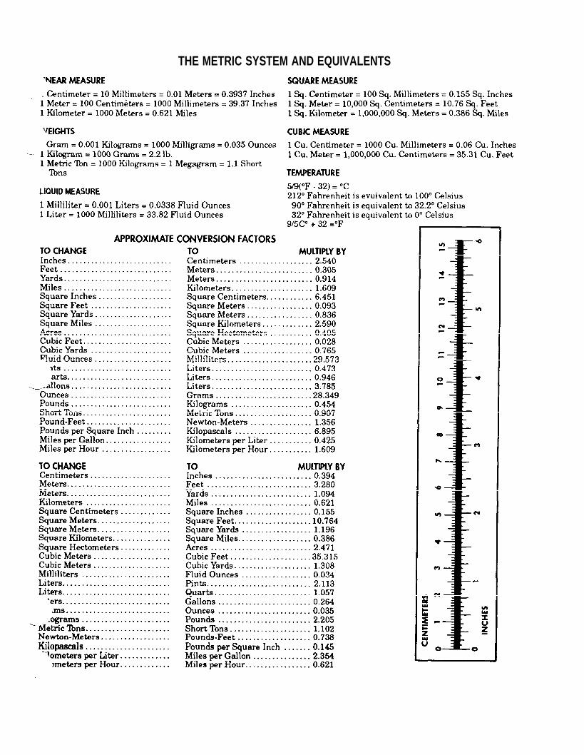
THE METRIC SYSTEM AND EQUIVALENTS

PIN: 016131-000
1

This fine document...
Was brought to you by me:
Liberated Manuals -- free army and government manuals
Why do I do it? I am tired of sleazy CD-ROM sellers, who take publicly available information, slap “watermarks” and other junk on it, and sell it. Those masters of search engine manipulation make sure that their sites that sell free information, come up first in search engines. They did not create it... They did not even scan it... Why should they get your money? Why are not letting you give those free manuals to your friends?
I am setting this document FREE. This document was made by the US Government and is NOT protected by Copyright. Feel free to share, republish, sell and so on.
I am not asking you for donations, fees or handouts. If you can, please provide a link to liberatedmanuals.com, so that free manuals come up first in search engines:
<A HREF=http://www.liberatedmanuals.com/>Free Military and Government Manuals</A>
– SincerelyIgor Chudovhttp://igor.chudov.com/
– Chicago Machinery Movers