metallurgical laboratory failure analysis · metallurgical laboratory failure analysis met 06-018...
TRANSCRIPT

Metallurgical Laboratory Failure Analysis MET 06-018
Page 1 of 12
Date: 2 March 2006 Customer: DSCC Part Name: Cable Assy, Firing Lead Part No.: 292AS110 Drawing No.: 292AS110B (Complete Assy)
292AS114B (Shield Assy, Brazed) NSN: 1095-00-151-4385 Serial Nos./Production Lot: 0251, 2509, 4094/Production Lots 1, 2, 3 Manufacturer: Elecsys Div. of DCX-CHOL (Cage 30463) Material and Treatment: Shield Assembly Silver Braze, Brazing Operation Prepared By: A. Gokhale Investigation: Metallurgical Evaluation of Braze Quality
1 INTRODUCTION
External examination of the braid/connector brazing for the subject shield assembly indicated that
the brazing may not meet drawing requirements (Drawing Nos. 292AS110B and 292AS114B for
Complete Assy and Shield Assy, respectively). The requirements per Shield Assy. Drawing No.
292AS114B, Note 3 are for a continuous circumferential fillet braze at the inner and outer mating
edges of the braid/connector mating surfaces using Silver Alloy AMS 4771.
A destructive metallurgical analysis of three Serial Numbers 0251, 2509 and 4094 was initiated on
28 February 2006.
2 MICROSTRUCTURAL ANALYSIS
Three braid/adapter end-connector shield assemblies (one for each serial number) were
longitudinally sectioned to reveal the mating surfaces. The sections cleaned ultrasonically to
remove sectioning debris, mounted in conductive plastic mounts, and prepared using standard
metallographic techniques to a final finish of 1 µm diamond. The polished sections were analyzed
by scanning electron microscopy and energy dispersive spectroscopy. In order to ensure that
metallographic artifacts did not influence the interfaces and their analysis, the interfaces and
microstructures were evaluated for evidence of damage. Regions of good interfacial bond were
noted as well as clear dendritic patterns within the braze regions indicating that the metallographic
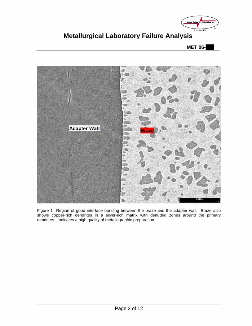
preparation did not adversely influence the braze evaluation. A region of good interface bonding
between the braze and adapter is shown in Figure 1. Note that the figure also shows a clear
dentritic solidification pattern in the braze material.
Metallurgical Laboratory Failure Analysis MET 06-018
Page 2 of 12
Figure 1 Region of good interface bonding between the braze and the adapter wall. Braze also shows copper-rich dendrites in a silver-rich matrix with denuded zones around the primary dendrites. Indicates a high quality of metallographic preparation.

Metallurgical Laboratory Failure Analysis MET 06-018
Page 3 of 12
Nomenclature
The adapter-side end (interface) was termed as the inner joint while the braid-side end was termed
the outer joint, as shown in Figure 1.
Figure 2 Nomenclature used in the metallurgical analysis descriptions.
Results of the metallographic section evaluations are presented individually for each serial number.
The braze composition was analyzed qualitatively for constituents by energy dispersive
spectroscopy (EDS). The results indicated that the braze contained a significantly smaller amount
of cadmium compared with the requirements of AMS 4771. A quantitative analysis with appropriate
standards is planned to confirm these findings.

Metallurgical Laboratory Failure Analysis MET 06-018
Page 4 of 12
Braze Joint Characterization for Serial No. 0251
The characterization indicated that
1. The amount of braze was insufficient for the joint volume.
2. Braze material was missing from a significant length of the joint, particularly near the outer end.
3. At the braze/adapter interface, there were regions of disbond, indicating deficient metallurgical bonding.
Figure 3 Overview of inner joint.

Metallurgical Laboratory Failure Analysis MET 06-018
Page 5 of 12
Figure 4 Overview of outer joint.
Figure 5 Inner joint detail.

Metallurgical Laboratory Failure Analysis MET 06-018
Page 6 of 12
Figure 6 Outer joint detail.

Metallurgical Laboratory Failure Analysis MET 06-018
Page 7 of 12
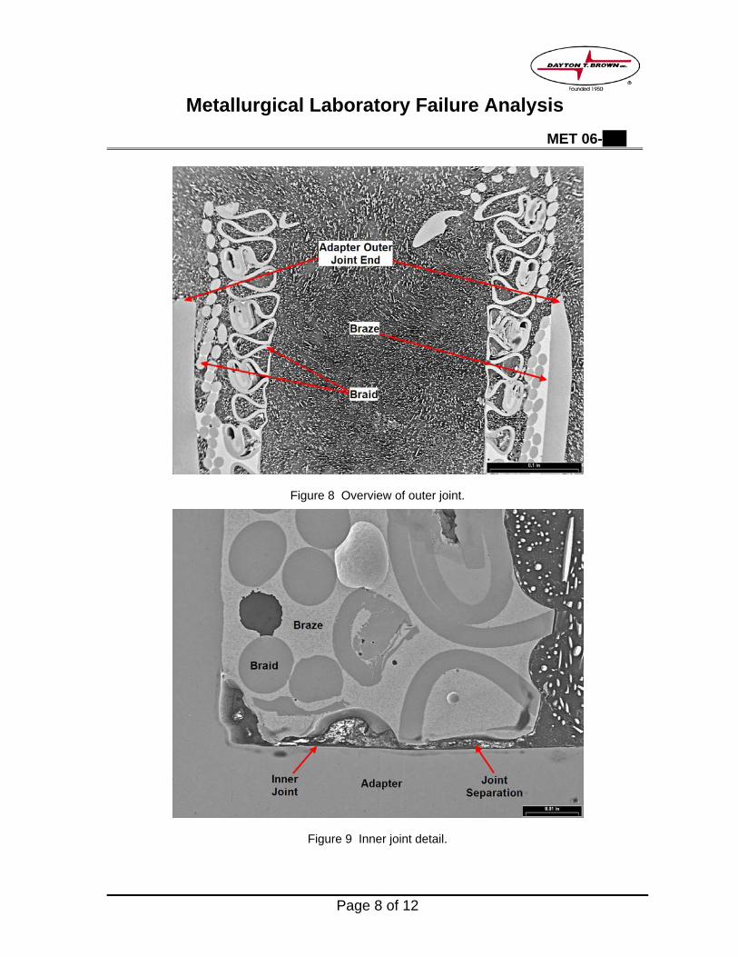
Braze Joint Characterization for Serial No. 2509
The characterization indicated that
1. The amount of braze was insufficient for the joint volume.
2. Braze material was missing from a significant length of the joint, particularly near the outer end.
3. At the braze/adapter interface, there were there were significant regions of disbond, indicating deficient metallurgical bonding.
Figure 7 Overview of inner joint.
Metallurgical Laboratory Failure Analysis MET 06-018
Page 8 of 12
Figure 8 Overview of outer joint.
Figure 9 Inner joint detail.
Metallurgical Laboratory Failure Analysis MET 06-018
Page 9 of 12
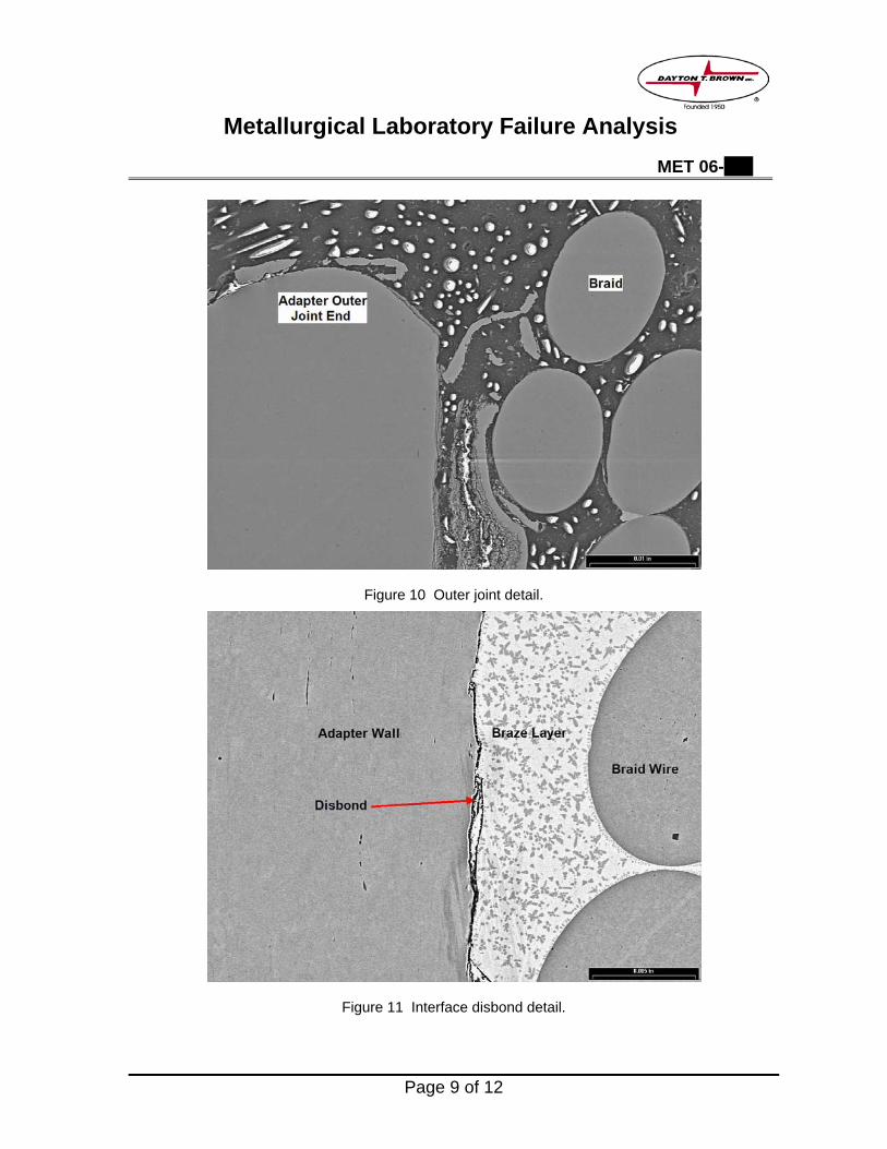
Figure 10 Outer joint detail.
Figure 11 Interface disbond detail.

Metallurgical Laboratory Failure Analysis MET 06-018
Page 10 of 12
Braze Joint Characterization for Serial No. 4094
The characterization indicated that
1. The amount of braze was insufficient for the joint volume.
2. Braze material was missing from a significant length of the joint, particularly near the outer end.
3. At the braze/adapter interface, there were there were significant regions of disbond, indicating deficient metallurgical bonding.
Figure 12 Overview of inner joint.

Metallurgical Laboratory Failure Analysis MET 06-018
Page 11 of 12
Figure 13 Overview of outer joint.
Figure 14 Inner joint detail.

Metallurgical Laboratory Failure Analysis MET 06-018
Page 12 of 12
Figure 14 Outer joint detail.
Figure 15 Interface disbond detail.